4.1 Thermodynamic Analysis of Control Volumes
4.1 Thermodynamic Analysis of Control Volumes
4.1 Thermodynamic Analysis of Control Volumes

You also want an ePaper? Increase the reach of your titles
YUMPU automatically turns print PDFs into web optimized ePapers that Google loves.
Mass and Volume Flow Rates:The amount <strong>of</strong> mass flowing through a cross-section per unit time is called the mass flow rateand is denoted by ṁ . In most practical applications, the mass flow rate in a pipe or duct can beevaluated using the following expression ...(<strong>4.1</strong>.2)where V av is the average bulk fluid velocity and A is the cross-sectional area normal to the flow direction.The volume flow rate V . is the volume <strong>of</strong> fluid flowing through a cross section per unit time and is givenby:V . = V av A(<strong>4.1</strong>.3)Thus, the mass flow and volume flow rates are related by: ṁ = V .(<strong>4.1</strong>.4)Conservation <strong>of</strong> Energy Principle:The first law <strong>of</strong> thermodynamics attributes the changes in total energy <strong>of</strong> a closed system toheat and work interactions. For control volumes, however, an additional mechanism can change theenergy <strong>of</strong> a system: mass flow in and out <strong>of</strong> the control volume! When mass enters a control volume, theenergy <strong>of</strong> the control volume increases because the entering mass carries energy with it. Likewise, whensome mass leaves the control volume, the energy contained within the control volume decreasesbecause the leaving mass takes out some energy with it. Then the conservation <strong>of</strong> energy equation for acontrol volume undergoing a process can be expressed as:(<strong>4.1</strong>.5)Q − W + E in − E out = E CVTotal energy cross- Total energy <strong>of</strong> Total energy <strong>of</strong> Net change ining boundary as mass entering CV mass leaving CV in energy <strong>of</strong> CVheat and workIf no mass enters or leaves the control volume, the second and third terms drop out and theabove equation becomes the first law for closed systems.Flow Work:Unlike closed systems, control volumes involve mass flow across their boundaries, and somework is required to push the mass into or out <strong>of</strong> the control volume. This is known as flow work, or flowenergy. The work done in pushing the fluid across the boundary (i.e. flow work) is:W flow = PV... and on a mass basis ... w flow = Pv(<strong>4.1</strong>.6)Total Energy <strong>of</strong> a Flowing Fluid:The total energy <strong>of</strong> closed system (non-flowing fluid) is expressed as:(<strong>4.1</strong>.7)ENGS205--Introductory <strong>Thermodynamic</strong>s page 39
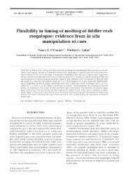
The fluid entering or leaving a control volume possesses an additional form <strong>of</strong> energy--the flowenergy Pv ! Then the total energy <strong>of</strong> a flowing fluid on a unit-mass basis (denoted θ) becomes:= Pv + e = Pv + ⎛ ⎝u + ke + pe⎞ ⎠(<strong>4.1</strong>.8)But the combination Pv+u has been previously defined as the enthalpy h. So the above relation reducesto:Note!(<strong>4.1</strong>.9)By using the enthalpy instead <strong>of</strong> the internal energy to represent the energy <strong>of</strong> aflowing fluid, you do not need to be concerned about the flow work!4.2 The Steady-Flow ProcessProcesses involving steady-flow devices (turbines, compressors, nozzles, etc...) can berepresented reasonably well by a somewhat idealized process, called the steady-flow process. Asteady-flow process can be defined as a process during which a fluid flows through a control volumesteadily. That is, the fluid properties can change from point to point within the control volume, but at anyfixed point they remain the same during the entire process. A steady-flow process is characterized bythe following:‚ No properties (intensive or extensive) within the control volume change with time. As a result,boundary work is zero for steady-flow systems.‚ No properties change at the boundaries (control surface) <strong>of</strong> the control volume with time.‚ The heat and work interactions between a steady-flow system and its surroundings do notchange with time.Conservation <strong>of</strong> Mass:During a steady-flow process, the total amount <strong>of</strong> mass contained within a control volume doesnot change with time. The conservation <strong>of</strong> mass principle for steady-flow systems requires that thetotal amount <strong>of</strong> mass entering a control volume equal the total amount leaving it (e.g. see figure below).m m 1 2CVm 3= m 1 + m 2ENGS205--Introductory <strong>Thermodynamic</strong>s page 39
The conservation <strong>of</strong> mass principle for a general steady-flow system with multiple inlets and exitscan be expressed in the rate form as:ṁ i = ṁ eTotal mass entering Total mass leavingCV per unit time CV per unit time(4.2.1)where the subscripts i stands for inlet and e for exit.Question to Think About!If the conservation <strong>of</strong> mass principle exists, what about conservation <strong>of</strong> volume? (Hint: thinkabout the definition <strong>of</strong> density (or specific volume) and compressibility!)Conservation <strong>of</strong> Energy:It was pointed out earlier that system properties remain constant for the duration <strong>of</strong> asteady-state process. In order for the total energy <strong>of</strong> an open system undergoing a steady-state processto remain constant, the amount <strong>of</strong> energy entering a control volume in all forms (heat, work, masstransfer) must be equal to the amount <strong>of</strong> energy leaving it. By this line <strong>of</strong> reasoning, the conservation<strong>of</strong> energy principle for a general steady-flow system with multiple inlets and exits can bemathematically stated as:Q . − Ẇ = ṁ e e − ṁ i iTotal energy crossing Total energy transported Total energy transportedboundary as heat and work out <strong>of</strong> CV with mass per into CV with mass perper unit time unit time unit timewhere θ is the tot al energy <strong>of</strong> the flowing fluid, including the flow work, per unit mass. Eq. (4.2.2) canalso be expressed as:(4.2.2)(4.2.3)Dividing Eq. (4.2.3) by ṁ gives the first law relation for control volumes on a unit-mass basis, or ...q − w = ⎛ ⎝h e + V e 22g c+ gz eg c⎞ ⎠− ⎛ ⎝h i + V i 22g c+ gz ig c(4.2.4)4.3 Some Steady-Flow Engineering DevicesMany engineering devices operate essentially under the same conditions for long periods <strong>of</strong> time(e.g. components <strong>of</strong> a steam power plant). Therefore, these devices can be conveniently analyzed assteady-flow devices.ENGS205--Introductory <strong>Thermodynamic</strong>s page 39
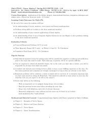
Nozzles and Diffusers:Nozzles and diffusers are commonly utilized in jet engines, rockets, spacecraft, and even gardenhoses. A nozzle is a device that increases the velocity <strong>of</strong> the fluid at the expense <strong>of</strong> pressure. Adiffuser is a device that increases the pressure <strong>of</strong> a fluid by slowing it down. The cross-sectional area <strong>of</strong>a nozzle decreases in the flow direction for subsonic flows and increases for supersonic flows. Thereverse is true for diffusers.NozzleDiffuserThe relative importance <strong>of</strong> the terms appearing in the energy equation for nozzles anddiffusers is as follows:‚ Q . 0: The rate <strong>of</strong> heat transfer between the fluid flowing through a nozzle or a diffuser andthe surroundings is usually very small. This is mainly due to the fluid's having high velocities and thus notspending enough time in the device for any significant heat transfer to take place. Therefore, in theabsence <strong>of</strong> heat transfer data, the flow through nozzles and diffusers may be assumed to be adiabatic.‚ Ẇ = 0: The work term for nozzles and diffusers is zero since these devices basically areproperly shaped ducts and they involve no shaft or electrical work.‚ KE 0: Nozzles and diffusers usually involve large changes in velocity. Therefore, kineticenergy changes must be accounted for in analyzing the flow through these devices.‚ PE 0: The fluid usually experiences little or no change in elevation and therefore thepotential energy term can be neglected.Turbines and Compressors:In power plants, the device that drives the electric generator is the turbine. As the fluid passesthrough the turbine, work is done against a blade that is attached to a shaft. As a result, the shaftrotates, and the turbine produces work. Compressors, as well as pumps, are devices used to increasethe pressure <strong>of</strong> a fluid (compressors are for gases and pumps are for liquids). Work is supplied to thesedevices from an external source through a rotating shaft (e.g. the A/C compressor in your car is driven <strong>of</strong>fa belt). Typical schematics <strong>of</strong> a turbine and compressor are shown on the next page.For turbines and compressors, the relative magnitudes <strong>of</strong> the various terms appearing in theenergy equation are as follows:‚ Q . 0: The heat transfer in these devices is generally small relative to the shaft work, unlessthere is intentional cooling.‚ Ẇ 0: All <strong>of</strong> these devices involve rotating shafts crossing their boundaries, and therefore thework term is important. For turbines, Ẇ represents the power output; for pumps and compressors, itrepresents the power input.ENGS205--Introductory <strong>Thermodynamic</strong>s page 39
CompressorShaftWork (-)TurbineShaftWork (+)‚ KE 0: The velocities involved with these devices, with the exception <strong>of</strong> turbines, areusually too low to cause any significant change in kinetic energy. In turbines, this change in kineticenergy is usually very small relative to the change in enthalpy, and is <strong>of</strong>ten disregarded.‚ PE 0: This energy term is typically small for turbines/compressors.Throttling Valves:Throttling valves are any kind <strong>of</strong> flow-restricting devices that cause a significant pressure dropin the fluid. Unlike turbines, throttling valves produce a pressure drop without any kind <strong>of</strong> work. Thepressure drop in the fluid is <strong>of</strong>ten accompanied by a large drop in temperature, and for that reasonthrottling devices are commonly used in refrigeration and air-conditioning applications. An adjustablethrottling valve is shown below.The relative magnitudes <strong>of</strong> the energy equation terms is discussed below ...‚ Q . 0: Flow through these devices is usually adiabatic.‚ Ẇ = 0: No work is done on or by the fluid.‚ KE 0: Even though the exit velocity is <strong>of</strong>ten considerably higher, the change in kineticenergy is insignificant.‚ PE 0: Potential energy changes are very small.The conservation <strong>of</strong> energy equation for a throttling valve readily reduces to:h eh i(4.3.1)... and for this reason, throttling valves are sometimes called isenthalpic devices.ENGS205--Introductory <strong>Thermodynamic</strong>s page 39
Mixing Chambers:In engineering applications, mixing two streams <strong>of</strong> fluids is not a rare occurrence. The sectionwhere the mixing process takes place is commonly referred to as a mixing chamber.MixingChamber<strong>Thermodynamic</strong> consideration <strong>of</strong> the mixing chamber reveals ...‚ Q . 0: Mixing chambers are usually well-insulated.‚ Ẇ = 0: There are no work interactions.‚ KE 0: Changes in kinetic energy are negligible.‚ PE 0: Changes in potential energy are negligible.Heat Exchangers:Heat exchangers are devices where two moving fluid streams exchange heat without mixing.Heat exchangers are used widely in industries, and they come in numerous designs. The simplest form<strong>of</strong> a heat exchanger is a double-tube (shown below) or tube-and-shell heat exchanger. It's composed <strong>of</strong>two concentric pipes <strong>of</strong> different diameters (i.e., a pipe within a pipe). One fluid flow in the inner pipe, andthe other in the annular space between the pipes. Heat is transferred through the wall separating the tw<strong>of</strong>luids.Fluid BFluid AHere are the relevant energy terms ...‚ Q . 0: This must be absolutely true! Otherwise, the heat exchanger you're analyzing doesn'texchange heat!ENGS205--Introductory <strong>Thermodynamic</strong>s page 39
‚ Ẇ = 0: Heat exchangers typically involve no work interactions.‚ KE PE 0: Changes in these forms <strong>of</strong> energy are usually negligible.Pipe and Duct Flow:The transport <strong>of</strong> liquids or gases in pipes and ducts is <strong>of</strong> great importance in many engineeringapplications. When flow through pipe or ducts is analyzed, the following points should be considered:‚ Q . 0: Under normal operating conditions, the amount <strong>of</strong> heat gained or lost by the fluid canbe very significant, particularly if the pipe or duct is long and not insulated.‚ Ẇ 0: If the control volume involves a heating section (electric wires, a fan, or a pump (shaft),the work interaction should be considered.‚ KE 0: For constant-diameter pipes/ducts, this energy term is usually negligible.‚ PE 0: Potential energy consideration are important when a fluid is pump through greatelevation changes.4.4 Unsteady-Flow ProcessesMany processes <strong>of</strong> engineering interest involve changes within the control volume with time.Such processes are called unsteady-flow, or transient-flow processes.Important point!The steady-flow relations developed in the previous sections are not applicable tothese processes!When an unsteady-flow process is analyzed, it is important to keep track <strong>of</strong> the mass and energycontents <strong>of</strong> the control volume as well as the energy interactions across the boundary. Some familiarunsteady flow processes are the charging <strong>of</strong> rigid vessels from supply lines, discharging a fluid from apressure vessel, inflating tires or balloons, and even cooking with an ordinary pressure cooker. Unlikesteady-flow processes, unsteady-flow processes start and end over a finite time period ∆t. Anotherdifference between steady and unsteady-flow processes is that steady-flow systems are fixed in space, insize, and in shape. Unsteady -flow systems, however, are not. They are usually stationary, but involvemoving boundaries (boundary work!)Conservation <strong>of</strong> Mass:Unlike the case <strong>of</strong> steady-flow processes, the amount <strong>of</strong> mass within the control volume doeschange with time during an unsteady-flow process. The degree <strong>of</strong> change depends on the amount <strong>of</strong>mass entering and leaving the control volume during the process. The conservation <strong>of</strong> massprinciple for unsteady-flow processes is mathematically stated as ...ENGS205--Introductory <strong>Thermodynamic</strong>s page 39
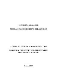
m i − m e = m CVTotal mass entering Total mass leaving Net change in massCV during ∆t CV during ∆t within CV during ∆t(4.<strong>4.1</strong>)If all the terms in Eq. (4.<strong>4.1</strong>) are divided by ∆t and taking the limit as t 0 gives ..(4.4.2)where dm CV / dt is the time rate <strong>of</strong> change <strong>of</strong> mass contained within the control volume.Conservation <strong>of</strong> Energy:Unlike the steady-flow process, the energy content <strong>of</strong> a control volume changes with time duringan unsteady-flow process. The degree <strong>of</strong> change depends on the amount <strong>of</strong> energy transfer across thesystem boundaries as heat and work as well as on the amount <strong>of</strong> energy transported into and out <strong>of</strong> thecontrol volume by mass during the process. That is, we have to keep track <strong>of</strong> the energy flowing into andout <strong>of</strong> the control volume for the duration <strong>of</strong> the unsteady process ∆t. The conservation <strong>of</strong> energyprinciple for a control volume undergoing an unsteady process for a time interval ∆t isQ − W + i − e = E CVTotal energy crossing Total energy trans- Total energy trans- Net change in energyboundary as heat and ported by mass into ported by mass out <strong>of</strong> <strong>of</strong> CV during ∆twork during ∆t CV during ∆t CV during ∆tIf all the terms in Eq. (4.4.3) are divided by ∆t and taking the limit as t 0 gives ...(4.4.3)(4.4.4). .where i and e are the rates at which energy is transported with mass into and out <strong>of</strong> the controlvolume respectively, and dE CV / dt is the time rate <strong>of</strong> change <strong>of</strong> energy within the control volume.In Eq. (4.4.3), the heat and work terms (Q and W) can be determined by external measurements.The total energy <strong>of</strong> the control volume at the beginning and end states <strong>of</strong> the process (E 1 and E 2 ) can beeasily determined by measuring the relevant properties <strong>of</strong> the substance at these two states. The totalenergy transported into or out <strong>of</strong> the control volume (Θ i , Θ e), however, is not as easy to determine sincethe properties <strong>of</strong> the mass at each inlet or exit may be changing with time as well as over thecross-section. Thus, the only way to determine the energy transport through an opening as a result <strong>of</strong>mass flow is to consider sufficiently small differential masses δm that have uniform properties and add totheir total energies.Total mass, mdivided up intonumerousdifferential masses,δmENGS205--Introductory <strong>Thermodynamic</strong>s page 39
The total energy <strong>of</strong> a flowing fluid <strong>of</strong> mass δm is θδm. Then the total energy transported by mass throughan inlet or exit (Θ i , Θ e) is obtained by integrating. At an inlet, for example, it becomes ...or, in the rate form ...(4.4.5)(4.4.6)The energy equation for unsteady-processes in control volumes becomes:(4.4.7)... and ...(4.4.8)Uniform-Flow Processes:A uniform-flow process is a simplified unsteady-flow process involving the following idealizations:‚ At any instant during the process, the state <strong>of</strong> the control volume is uniform (the samethroughout spatially). Therefore, the state <strong>of</strong> the mass exiting the control volume at any instant is thesame as the state <strong>of</strong> the mass in the control volume at that instant.‚ The fluid properties may differ from one inlet or exit to another, but the fluid flow at an inlet orexit is uniform and steady.Under these idealizations, Eq. (4.4.7) becomes ...(4.4.9)where u 1 and u 2 are the initial and final specific internal energies <strong>of</strong> the system.ENGS205--Introductory <strong>Thermodynamic</strong>s page 39