FEMA P-259 - Hazard Mitigation Web Portal
FEMA P-259 - Hazard Mitigation Web Portal
FEMA P-259 - Hazard Mitigation Web Portal
- No tags were found...

You also want an ePaper? Increase the reach of your titles
YUMPU automatically turns print PDFs into web optimized ePapers that Google loves.
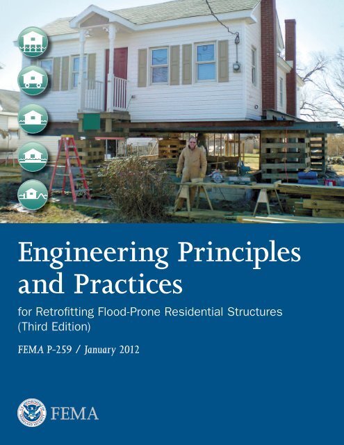
Engineering Principlesand Practicesfor Retrofitting Flood-Prone Residential Structures(Third Edition)<strong>FEMA</strong> P-<strong>259</strong> / January 2012
About the CoverAfter his Poquoson house suffered flood damage in November 2009, the owner decided to elevate thehome to avoid future damages. The home was elevated an additional foot above the 1 foot freeboardrequired by the local ordinance. The finished floor is now 2 feet above the base flood elevation.
ENGINEERING PRINCIPLES AND PRACTICESThe following people are involved with the update of <strong>FEMA</strong> P-<strong>259</strong>.The previous edition was produced in 2001.Third Edition Authors and Key ContributorsDavid Conrad, P.E., Atkins GlobalOmar Kapur, URS Group, Inc.Amit Mahadevia, URS Group, Inc.Desi Maldonado, P.E., Atkins GlobalJulia Moline, CFM, DewberryGlenn Overcash, P.E., URS Group, Inc.Samantha Passman, URS Group, Inc.Manuel Perotin, P.E., CFM, Atkins GlobalAdam Reeder, P.E., CFM, Atkins GlobalLaura Seitz, CFM, URS Group, Inc.Adrienne Sheldon, P.E., CFM, URS Group, Inc.John Squerciati, P.E., CFM, DewberryThird Edition ReviewersGene Barr, CFMBrooke Buchanan, P.E., CFM, <strong>FEMA</strong> Region VIIIJamin Buckingham, Wolfe House MoversWilliam Coulbourne, P.E., Applied Technology CouncilPaul Gugenheim, P.E., Delta Structural Technology, Inc.Michael Hornick, <strong>FEMA</strong> Region IXJohn Ingargiola, CFM, <strong>FEMA</strong> HeadquartersChristopher P. Jones, P.E., Durham, NCJohn Plisich, <strong>FEMA</strong> Region IVEd Smith, <strong>FEMA</strong> HeadquartersJody Springer, <strong>FEMA</strong> HeadquartersPaul Tertell, P.E., <strong>FEMA</strong> HeadquartersScott Tezak, P.E., TRC SolutionsGregory Wilson, CFM, <strong>FEMA</strong> HeadquartersThird Edition Technical Editing, Layout, and IllustrationDeb Daly, Greenhorne & O’MaraJulie Liptak, Greenhorne & O’MaraLee-Ann Lyons, URS Group, Inc.Billy Ruppert, URS Group, Inc.Devika Strother, URS Group, Inc.AcknowledgmentsENGINEERING PRINCIPLES AND PRACTICES for Retrofitting Flood-Prone Residential Structuresi
ENGINEERING PRINCIPLES AND PRACTICESContentsChapter 1. Introduction to Retrofitting ..........................................................................................1-11.1 Goals and Intended Users............................................................................................................ 1-11.2 Organization of the Manual........................................................................................................ 1-21.3 Methods of Retrofitting...............................................................................................................1-41.3.1 Elevation..........................................................................................................................1-51.3.1.1 Elevation on Solid Perimeter Foundation Walls............................................... 1-61.3.1.2 Elevation on Open Foundation Systems...........................................................1-71.3.2 Relocation......................................................................................................................1-111.3.3 Dry Floodproofing.........................................................................................................1-121.3.4 Wet Floodproofing.........................................................................................................1-141.3.5 Floodwalls and Levees ...................................................................................................1-161.4 Considerations When Retrofitting..............................................................................................1-191.5 Retrofitting Process....................................................................................................................1-191.5.1 Other Retrofitting Guides..............................................................................................1-21Chapter 2. Regulatory Requirements ........................................................................................... 2-12.1 National Flood Insurance Program..............................................................................................2-22.1.1 Flood <strong>Hazard</strong> Information.............................................................................................. 2-32.1.1.1 Flood Insurance Rate Maps............................................................................. 2-32.1.1.2 Flood Insurance Studies.................................................................................. 2-72.1.2 Floodplain Management Regulations.............................................................................. 2-92.1.3 Insurance Program.........................................................................................................2-102.1.4 NFIP Flood-Prone Building Performance Requirements................................................2-112.2 Community Regulations and the Permitting Process................................................................. 2-122.3 National Model Building Codes................................................................................................ 2-132.4 Consensus Standards................................................................................................................. 2-14Chapter 3. Parameters of Retrofitting ......................................................................................... 3-13.1 Determination of Homeowner Preferences..................................................................................3-23.1.1 The Initial Homeowner Meeting..................................................................................... 3-23.1.2 Initial Site Visit...............................................................................................................3-43.1.3 Aesthetic Concerns......................................................................................................... 3-5ENGINEERING PRINCIPLES AND PRACTICES for Retrofitting Flood-Prone Residential Structuresiii
CONTENTS3.1.4 Economic Considerations................................................................................................3-63.1.5 Risk Considerations........................................................................................................ 3-93.1.6 Accessibility for Individuals with Special Needs.............................................................. 3-93.2 Community Regulations and Permitting................................................................................... 3-103.2.1 Local Codes...................................................................................................................3-103.2.2 Building Systems/Code Upgrades..................................................................................3-103.2.3 Off-Site Flooding Impacts..............................................................................................3-113.3 Technical Parameters................................................................................................................. 3-113.3.1 Flooding Characteristics................................................................................................ 3-133.3.1.1 Flood Depth and Elevation............................................................................3-143.3.1.2 Flood Flow Velocity........................................................................................3-153.3.1.3 Flood Frequency.............................................................................................3-163.3.1.4 Rates of Rise and Fall.....................................................................................3-163.3.1.5 Flood Duration..............................................................................................3-163.3.1.6 Debris Impact................................................................................................3-163.3.2 Site Characteristics.........................................................................................................3-173.3.2.1 Site Location..................................................................................................3-173.3.2.2 Vulnerability to Erosion..................................................................................3-173.3.2.3 Soil Type........................................................................................................3-183.3.3 Building Characteristics.................................................................................................3-193.3.3.1 Substructure.................................................................................................. 3-203.3.3.2 Superstructure............................................................................................... 3-203.3.3.3 Support Services............................................................................................ 3-213.3.3.4 Building Construction................................................................................... 3-213.3.3.5 Building Condition....................................................................................... 3-213.4 Balancing Historic Preservation With Flood Protection............................................................. 3-253.5 Multiple <strong>Hazard</strong>s....................................................................................................................... 3-253.5.1 Earthquake Forces......................................................................................................... 3-263.5.2 Wind Forces ................................................................................................................. 3-26Chapter 4. Determination of <strong>Hazard</strong>s .......................................................................................... 4-14.1 Analysis of Flood-Related <strong>Hazard</strong>s..............................................................................................4-14.1.1 Determining Flood Elevations........................................................................................ 4-34.1.1.1 Riverine Areas................................................................................................. 4-34.1.1.2 Coastal Areas..................................................................................................4-64.1.2 Flood Forces and Loads................................................................................................... 4-84.1.2.1 Flood Depth and Floodproofing Design Depth............................................... 4-84.1.2.2 Hydrostatic Forces..........................................................................................4-104.1.2.3 Lateral Hydrostatic Forces..............................................................................4-11ivENGINEERING PRINCIPLES AND PRACTICES for Retrofitting Flood-Prone Residential Structures
CONTENTS4.1.2.4 Saturated Soil Forces..................................................................................... 4-124.1.2.5 Combined Saturated Soil and Water Forces................................................... 4-134.1.2.6 Vertical Hydrostatic Forces.............................................................................4-144.1.2.7 Hydrodynamic Forces....................................................................................4-164.1.2.8 High Velocity Hydrodynamic Forces............................................................. 4-204.1.2.9 Impact Loads................................................................................................. 4-214.1.2.10 Riverine Erosion............................................................................................ 4-244.1.3 Site Drainage................................................................................................................ 4-254.1.4 Movable Bed Streams.................................................................................................... 4-304.1.5 Analysis of Non-Flood-Related <strong>Hazard</strong>s........................................................................ 4-304.1.6 Wind Forces.................................................................................................................. 4-314.1.7 Seismic Forces............................................................................................................... 4-354.1.8 Combining Forces......................................................................................................... 4-364.1.9 Protection of the Structure............................................................................................ 4-364.1.10 Protection of Non-Structural Building Components and Building Contents................ 4-374.1.11 Land Subsidence........................................................................................................... 4-374.2 Geotechnical Considerations.....................................................................................................4-384.2.1 Allowable Bearing Capacity..........................................................................................4-404.2.2 Scour Potential..............................................................................................................4-424.2.2.1 Frost Zone Considerations.............................................................................4-484.2.2.2 Permeability..................................................................................................4-484.2.2.3 Shrink-Swell Potential................................................................................... 4-50Chapter 5. General Design Practices ........................................................................................... 5-15.1 Field Investigation.......................................................................................................................5-35.1.1 Local Building Requirements.......................................................................................... 5-35.1.2 Surveys............................................................................................................................ 5-35.1.3 Structure Survey............................................................................................................. 5-35.1.4 Topographic Survey........................................................................................................5-45.1.5 Site Utilities Survey......................................................................................................... 5-55.1.6 <strong>Hazard</strong> Determinations...................................................................................................5-65.1.7 Documentation of Existing Building Systems.................................................................5-65.1.8 Homeowner Preferences.................................................................................................5-105.1.9 Homeowner Coordination.............................................................................................5-105.1.10 Maintenance Programs and Emergency Action Plans.....................................................5-105.2 Analysis of Existing Structure.................................................................................................... 5-115.2.1 Structural Reconnaissance.............................................................................................5-115.2.2 Footings and Foundation Systems................................................................................. 5-125.2.3 Bearing Capacity of Footings........................................................................................ 5-135.2.4 Bearing Capacity of Foundation Walls ..........................................................................5-15ENGINEERING PRINCIPLES AND PRACTICES for Retrofitting Flood-Prone Residential Structuresv
CONTENTS5.2.5 Lateral Loads.................................................................................................................5-155.2.6 Vertical Loads................................................................................................................5-175.2.7 Dead Loads....................................................................................................................5-175.2.8 Live Loads......................................................................................................................5-195.2.9 Roof Snow Loads.......................................................................................................... 5-205.2.10 Calculation of Vertical, Dead, Live, and Snow Loads.................................................... 5-205.2.11 Capacity versus Loading................................................................................................ 5-245.2.12 Load Combination Scenarios........................................................................................ 5-245.2.13 Strength Design Method............................................................................................... 5-255.2.14 Allowable Stress Method............................................................................................... 5-27Chapter 5D. Dry Floodproofing ................................................................................................... 5D-15D.1 Emergency Operations Plan......................................................................................................5D-35D.2 Inspection and Maintenance Plan.............................................................................................5D-35D.3 Sealants and Shields..................................................................................................................5D-35D.4 Field Investigation....................................................................................................................5D-95D.5 Confirm Structure is Designed to Accommodate Dry Floodproofing Measures..................... 5D-105D.6 Selection and Design of Sealant Systems................................................................................. 5D-165D.6.1 Coatings...................................................................................................................5D-175D.6.2 Wrapped Systems......................................................................................................5D-175D.6.3 Brick Veneer Systems............................................................................................... 5D-205D.7 Selection and Design of Shield Systems..................................................................................5D-225D.7.1 Plate Shields............................................................................................................. 5D-225D.8 Construction Considerations for Sealants and Shields............................................................ 5D-255D.9 Drainage Collection Systems.................................................................................................. 5D-255D.9.1 French Drains.......................................................................................................... 5D-285D.9.2 Exterior Underdrain Systems................................................................................... 5D-285D.9.3 Interior Drain System ............................................................................................. 5D-295D.9.4 Types of Sump Pumps............................................................................................. 5D-315D.9.5 Infiltration versus Inundation ................................................................................. 5D-325D.9.6 Coordination with Other Floodproofing Methods.................................................. 5D-335D.9.7 Field Investigation................................................................................................... 5D-335D.9.8 Design..................................................................................................................... 5D-355D.10 Backflow Valves .....................................................................................................................5D-395D.10.1 Field Investigation...................................................................................................5D-405D.10.2 Design..................................................................................................................... 5D-415D.11 Emergency Power...................................................................................................................5D-435D.11.1 Field Investigation...................................................................................................5D-435D.11.2 Design.....................................................................................................................5D-445D.11.3 Construction .......................................................................................................... 5D-50viENGINEERING PRINCIPLES AND PRACTICES for Retrofitting Flood-Prone Residential Structures
CONTENTS5D.12 Non-Residential Construction................................................................................................5D-505D.12.1 Permanent Closure of Openings.............................................................................. 5D-505D.12.2 Watertight Core Areas..............................................................................................5D-515D.12.3 Enhanced Flood Shields.......................................................................................... 5D-525D.12.4 Moveable Floodwalls............................................................................................... 5D-525D.12.5 Pressure Relief Systems............................................................................................ 5D-54Chapter 5E. Elevation .................................................................................................................... 5E-15E.1 Types of Residential Structures that Can Be Elevated................................................................5E-25E.1.1 Houses Over a Crawlspace............................................................................................5E-25E.1.2 Houses Over Basements ...............................................................................................5E-85E.1.2.1 Design of Openings in Foundation Walls for Intentional Floodingof Enclosed Areas Below the DFE .............................................................................. 5E-115E.1.3 Houses on Piers, Columns, or Piles............................................................................. 5E-135E.1.4 Slab-on-Grade Houses................................................................................................ 5E-135E.1.4.1 Elevating a Slab-on-Grade Wood-Frame House.......................................... 5E-145E.1.4.2 Elevating a Slab-on-Grade Masonry House................................................. 5E-195E.1.5 Heavy Building Materials/Complex Design................................................................ 5E-195E.2 Field Investigation Concerns....................................................................................................5E-225E.2.1 Property Inspection and Existing Data Review...........................................................5E-225E.2.2 Code Search................................................................................................................5E-225E.3 Design.....................................................................................................................................5E-245E.4 Construction Considerations...................................................................................................5E-305E.4.1 Slab-on-Grade House, Not Raising Slab with House..................................................5E-305E.4.2 Slab-on-Grade House, Raising Slab ........................................................................... 5E-315E.4.3 House Over Crawlspace/Basement.............................................................................. 5E-315E.4.4 House on Piers, Columns, or Piles.............................................................................. 5E-32Chapter 5F. Floodwalls and Levees ............................................................................................ 5F-15F.1 Floodwalls.................................................................................................................................5F-25F.1.1 Types of Floodwalls....................................................................................................... 5F-25F.1.1.1 Gravity Floodwall.......................................................................................... 5F-25F.1.1.2 Cantilever Floodwall.....................................................................................5F-45F.1.1.3 Buttressed Floodwall.....................................................................................5F-65F.1.1.4 Counterfort Floodwall................................................................................... 5F-75F.1.2 Field Investigation for Floodwalls.................................................................................. 5F-85F.1.3 Floodwall Design.........................................................................................................5F-105F.1.3.1 Floodwall Design (Selection and Sizing).......................................................5F-105F.1.3.2 Floodwall Design (Simplified Approach)..................................................... 5F-295F.1.4 Floodwall Appurtenances.............................................................................................5F-31ENGINEERING PRINCIPLES AND PRACTICES for Retrofitting Flood-Prone Residential Structuresvii
CONTENTS5F.1.4.1 Floodwall Closures.......................................................................................5F-315F.1.4.2 Drainage Systems........................................................................................ 5F-395F.1.5 Floodwall Seepage and Leakage..................................................................................5F-425F.1.5.1 Seepage Through the Floodwall...................................................................5F-425F.1.5.2 Seepage Under the Floodwall......................................................................5F-425F.1.5.3 Leakage Between the Floodwall and Residence...........................................5F-435F.1.6 Floodwall Architectural Details..................................................................................5F-435F.1.7 Floodwall Construction.............................................................................................. 5F-475F.2 Levees......................................................................................................................................5F-485F.2.1 Levee Field Investigation.............................................................................................5F-485F.2.2 Levee Design............................................................................................................... 5F-495F.2.2.1 Standard Levee Design Criteria................................................................... 5F-495F.2.2.2 Initial Levee Design Phases..........................................................................5F-515F.2.3 Levee Seepage Concerns...............................................................................................5F-515F.2.3.1 Scouring/Levee Slope Protection..................................................................5F-525F.2.3.2 Interior Levee Drainage................................................................................5F-535F.2.3.3 Levee Maintenance...................................................................................... 5F-545F.2.3.4 Levee Cost................................................................................................... 5F-545F.2.4 Levee Construction..................................................................................................... 5F-565F.2.4.1 Levee Soil Suitability................................................................................... 5F-565F.2.4.2 Levee Compaction Requirements................................................................ 5F-565F.2.4.3 Levee Settlement Allowance........................................................................ 5F-565F.2.4.4 Levee Borrow Area Restrictions................................................................... 5F-565F.2.4.5 Access Across Levee..................................................................................... 5F-57Chapter 5R. Relocation ..................................................................................................................5R-15R.1 Step 1: Select the House Moving Contractor.............................................................................5R-25R.2 Step 2: Analyze the Existing Site and Structure........................................................................ 5R-45R.3 Step 3: Select, Analyze, and Design the New Site......................................................................5R-55R.4 Step 4: Prepare the Existing Site............................................................................................... 5R-65R.5 Step 5: Analyze and Prepare the Moving Route........................................................................ 5R-65R.6 Step 6: Prepare the Structure.....................................................................................................5R-75R.7 Step 7: Prepare the New Site....................................................................................................5R-105R.8 Step 8: Move the Structure......................................................................................................5R-115R.9 Step 9: Restore the Old Site.....................................................................................................5R-13Chapter 5W. Wet Floodproofing .................................................................................................5W-15W.1 Protection of the Structure...................................................................................................... 5W-25W.1.1 Foundations ..............................................................................................................5W-3viiiENGINEERING PRINCIPLES AND PRACTICES for Retrofitting Flood-Prone Residential Structures
CONTENTS5W.1.2 Cavity Walls..............................................................................................................5W-35W.1.3 Solid Walls .............................................................................................................. 5W-45W.2 Use of Flood-Resistant Materials............................................................................................. 5W-45W.3 Building Operations and Maintenance Procedures and Emergency Preparedness Plans........... 5W-55W.3.1 Flood Warning System .............................................................................................5W-55W.3.2 Inspection and Maintenance Plan .............................................................................5W-55W.3.3 Emergency Operations Plan ......................................................................................5W-55W.3.4 Protection of Utility Systems.................................................................................... 5W-65W.4 Elevation ................................................................................................................................ 5W-75W.5 In-Place Protection.................................................................................................................. 5W-75W.6 Field Investigation................................................................................................................... 5W-85W.7 Design Overview....................................................................................................................5W-115W.8 Electrical Systems...................................................................................................................5W-115W.9 Heating, Ventilating, and Air Conditioning Systems .............................................................5W-135W.10 Fuel Supply/Storage Systems...................................................................................................5W-135W.11 Water Systems........................................................................................................................5W-155W.12 Sewer Systems.........................................................................................................................5W-155W.13 Calculation of Buoyancy Forces..............................................................................................5W-165W.14 Construction/Implementation................................................................................................5W-18Chapter 6. Case Studies ................................................................................................................. 6-16.1 Case Study #1: Residential Retrofit in Riverine Floodplain Using Elevation or Relocation..........6-16.1.1 Description of Property................................................................................................... 6-16.1.2 Structure Information..................................................................................................... 6-26.1.3 Retrofit Options Selection...............................................................................................6-46.1.4 Load Calculations........................................................................................................... 6-96.1.5 Supporting Documentation...........................................................................................6-156.1.6 Real World Examples.................................................................................................... 6-236.2 Case Study #2: Residential Retrofit in Coastal A Zone Using Elevation or Acquisition.............6-246.2.1 Description of Property................................................................................................. 6-246.2.2 Structure Information................................................................................................... 6-246.2.3 Retrofit Options Selection............................................................................................. 6-266.2.4 Load Calculations......................................................................................................... 6-306.2.5 Supporting Documentation.......................................................................................... 6-336.2.6 Real World Examples.................................................................................................... 6-396.3 Case Study #3: Residential Retrofit Outside of the Floodplain Using Dry or WetFloodproofing............................................................................................................................6-406.3.1 Description of Property.................................................................................................6-406.3.2 Structure Information...................................................................................................6-406.3.3 Retrofit Options Selection.............................................................................................6-43ENGINEERING PRINCIPLES AND PRACTICES for Retrofitting Flood-Prone Residential Structuresix
CONTENTS6.3.4 Load Calculations.........................................................................................................6-466.3.5 Supporting Documentation...........................................................................................6-516.3.6 Real World Examples.................................................................................................... 6-576.4 Case Study #4: Residential Retrofit Outside of the Floodplain Using Floodwalls or Levees .....6-596.4.1 Description of Property................................................................................................. 6-596.4.2 Structure Information................................................................................................... 6-596.4.3 Retrofit Options Selection.............................................................................................6-606.4.4 Load Calculations.........................................................................................................6-646.4.5 Drainage Requirements.................................................................................................6-646.4.6 Supporting Documentation..........................................................................................6-666.4.7 Real World Examples.................................................................................................... 6-70AppendicesAppendix A. Sources of <strong>FEMA</strong> Funding..................................................................................................A-1Appendix B. Understanding the <strong>FEMA</strong> Benefit-Cost Analysis Process....................................................B-1Appendix C. Sample Design Calculations............................................................................................... C-1Appendix D. Alluvial Fan Flooding........................................................................................................D-1Appendix E. References............................................................................................................................E-1Appendix F. Other Resources...................................................................................................................F-1Appendix G. Summary of NFIP Requirements and Best Practices..........................................................G-1Appendix H. Acronyms...........................................................................................................................H-1List of FiguresChapter 1Figure 1-1. Elevation on solid perimeter foundation walls................................................................. 1-6Figure 1-2.Elevation of existing residence on extended foundation walls...........................................1-7Figure 1-3. Elevation on piers............................................................................................................ 1-8Figure 1-4. Elevation on posts or columns......................................................................................... 1-8Figure 1-5. Elevation on piles............................................................................................................ 1-9Figure 1-6.Figure 1-7.Figure 1-8.Figure 1-9.Structure elevated on piles..............................................................................................1-10Structure placed on a wheeled vehicle for relocation to a new site...................................1-11Structure to be relocated................................................................................................1-12Dry floodproofed structure............................................................................................1-13xENGINEERING PRINCIPLES AND PRACTICES for Retrofitting Flood-Prone Residential Structures
CONTENTSFigure 1-10.Figure 1-11.Figure 1-12.Figure 1-13.Wet floodproofed structure............................................................................................1-15Structure protected by floodwall and levee.....................................................................1-17Home protected by a levee.............................................................................................1-17Primary steps in retrofitting process...............................................................................1-20Chapter 2Figure 2-1.Figure 2-2.Typical DFIRM for riverine flooding..............................................................................2-4Typical DFIRM for coastal flooding showing the Limit of Moderate Wave Action(LiMWA)........................................................................................................................ 2-5Figure 2-3. Typical riverine floodplain cross section.......................................................................... 2-7Figure 2-4. Wave height transect showing LiMWA, MoWA, and MiWA.......................................... 2-8Chapter 3Figure 3-1. Preliminary Floodproofing/Retrofitting Preference Matrix.............................................. 3-3Figure 3-2.Survey to identify the low point of floodwater entry into a typical residentialstructure.......................................................................................................................... 3-5Figure 3-3. Preliminary Cost Estimating Worksheet......................................................................... 3-8Figure 3-4. Retrofitting Screening Matrix....................................................................................... 3-12Figure 3-5. Instructions for Retrofitting Screening Matrix.............................................................. 3-13Figure 3-6.Figure 3-7.Figure 3-8.Figure 3-9.Measuring mud lines or high water marks to establish flood depth................................3-14Hydrostatic and buoyancy forces....................................................................................3-15Large, fast-moving waves combined with erosion and scour to destroy thisGulf of Mexico home during Hurricane Opal................................................................3-18Lateral and buoyancy forces resulting from saturated soil...............................................3-19Figure 3-10. Preliminary Building Condition Worksheet.................................................................. 3-23Chapter 4Figure 4-1. Flood-related hazards...................................................................................................... 4-2Figure 4-2.House and stream location on the DFIRM.....................................................................4-4Figure 4-3. House location on flood profile for Big Branch (Stream 21)............................................. 4-5ENGINEERING PRINCIPLES AND PRACTICES for Retrofitting Flood-Prone Residential Structuresxi
CONTENTSFigure 4-4. Coastal DFIRM showing house location and flood elevation.......................................... 4-7Figure 4-5.Figure 4-6.Figure 4-7.Flood depth and design depth........................................................................................4-10Hydrostatic forces..........................................................................................................4-11Diagram of hydrostatic forces.........................................................................................4-11Figure 4-8. Combination soil/water hydrostatic and buoyancy forces.............................................. 4-13Figure 4-9.Figure 4-10.Figure 4-11.Hydrostatic Force Computation Worksheet...................................................................4-15Hydrodynamic and impact forces..................................................................................4-16Equivalent Hydrostatic Force Computation Worksheet..................................................4-19Figure 4-12. Hydrodynamic Force (High Velocity) Computation Worksheet.................................... 4-21Figure 4-13. Impact Force Computation Worksheet.......................................................................... 4-24Figure 4-14. Rectangular area enclosed by a floodwall or levee.......................................................... 4-26Figure 4-15. Rectangular area partially enclosed by a floodwall or levee............................................ 4-27Figure 4-16. Interior Drainage Computation Worksheet................................................................... 4-29Figure 4-17. Non-flood-related natural hazards................................................................................. 4-31Figure 4-18. Wind-induced pressures on a building.......................................................................... 4-32Figure 4-19A. Basic wind speed map................................................................................................... 4-33Figure 4-19B. Regions where wind design is required.......................................................................... 4-34Figure 4-20. Seismic design process................................................................................................... 4-35Figure 4-21. Seismic design causes and effects................................................................................... 4-36Figure 4-22. Geotechnical Considerations Decision Matrix.............................................................. 4-39Figure 4-23.Figure 4-24.Figure 4-25.Figure 4-26.Localized scour at piers, posts, and piles........................................................................4-42Scour action on a ground level building........................................................................4-43Process for estimating potential scour depth..................................................................4-44Flow Angle of Attack....................................................................................................4-46Figure 4-27. Terminating stratum..................................................................................................... 4-47Figure 4-28. Additional embedment for foundation member............................................................ 4-47xiiENGINEERING PRINCIPLES AND PRACTICES for Retrofitting Flood-Prone Residential Structures
CONTENTSChapter 5Figure 5-1. Design process................................................................................................................ 5-2Figure 5-2. Mechanical, Electrical, Plumbing, and Related Building Systems Data Sheet.................. 5-7Figure 5-3. Structural Reconnaissance Worksheet........................................................................... 5-12Figure 5-4. Foundation system loading........................................................................................... 5-13Figure 5-5.Building Weight Estimating Worksheet.........................................................................5-19Figure 5-6. Column tributary area.................................................................................................. 5-22Figure 5-7. Wall/girder tributary area.............................................................................................. 5-22Chapter 5DFigure 5D-1. Process of selection and design for dry floodproofing................................................... 5D-2Figure 5D-2.Figure 5D-3.Figure 5D-4.A way to seal an existing brick-faced wall is to add an additional layer of brickwith a seal in between..................................................................................................5D-4A wrapped house sealing system can be used to protect against fast transientlow-level flooding......................................................................................................... 5D-5A shield hinged at its bottom could prevent low-level flooding from entering agarage or driveway........................................................................................................5D-6Figure 5D-5. A door opening may be closed using a variety of materials for shields........................... 5D-7Figure 5D-6. A shield can help prevent low-level flooding from entering through a doorway............. 5D-7Figure 5D-7.Figure 5D-8.Figure 5D-9.Where a window is exposed to a flood, bricking up the opening could eliminatethe hazard.................................................................................................................... 5D-8Dry floodproofed homes should have an effective drainage system aroundfootings and slabs to reduce water pressure on foundation walls and basements........... 5D-8Illustration of hydrostatic force....................................................................................5D-10Figure 5D-10. Existing building structural evaluations......................................................................5D-11Figure 5D-11. This house located in the SFHA was displaced from its foundation into theroadway adjacent to it................................................................................................. 5D-12Figure 5D-12. The photo on the right shows the house’s original location......................................... 5D-12Figure 5D-13. Typical design strip for reinforced masonry................................................................ 5D-13ENGINEERING PRINCIPLES AND PRACTICES for Retrofitting Flood-Prone Residential Structuresxiii
CONTENTSFigure 5D-14. This house’s foundation walls were not able to withstand the forces appliedduring or after the flood............................................................................................. 5D-13Figure 5D-15. Typical slab uplift failure.............................................................................................5D-14Figure 5D-16. This house’s foundation was rebuilt after collapse from saturated soil forcesafter a flood.................................................................................................................5D-16Figure 5D-17. Selection of sealants/coatings.......................................................................................5D-17Figure 5D-18. Selection and design of wrapped sealant systems.........................................................5D-18Figure 5D-19. Plan view of wall section.............................................................................................5D-19Figure 5D-20. Selection/design of a brick veneer sealant system........................................................ 5D-21Figure 5D-21. Selection/design of plate shields.................................................................................. 5D-23Figure 5D-22. Typical residential masonry block wall construction................................................... 5D-26Figure 5D-23. Common faults contributing to seepage into basements............................................. 5D-27Figure 5D-24. Typical French drain system....................................................................................... 5D-28Figure 5D-25. Typical exterior underdrain system with sump pump showing two alternativeconfigurations in the side view................................................................................... 5D-29Figure 5D-26. Details of a combination underdrain and foundation waterproofing system............... 5D-30Figure 5D-27. Typical interior drain systems..................................................................................... 5D-30Figure 5D-28. Types of sump pumps................................................................................................ 5D-31Figure 5D-29. Foundation wall failure due to pumping out basement while ground wasstill saturated with water............................................................................................ 5D-33Figure 5D-30. Sump Pump Field Investigation Worksheet................................................................ 5D-34Figure 5D-31. Sump pump design process........................................................................................ 5D-35Figure 5D-32. Typical sump detail.................................................................................................... 5D-36Figure 5D-33. Backflow valve...........................................................................................................5D-40Figure 5D-34. Backflow valve selection.............................................................................................5D-40Figure 5D-35. Backflow Valve Field Investigation Worksheet............................................................ 5D-41Figure 5D-36. Emergency power design process................................................................................5D-44Figure 5D-37. Permanent closure of an opening to prevent floodwaters from entering thebuilding......................................................................................................................5D-51xivENGINEERING PRINCIPLES AND PRACTICES for Retrofitting Flood-Prone Residential Structures
CONTENTSFigure 5D-38. A watertight door used to protect mechanical rooms for a hospital subject tofloodwaters................................................................................................................. 5D-52Figure 5D-39. Flood shields that can be raised and lowered to protect a hospital mechanicalroom from floodwaters............................................................................................... 5D-53Figure 5D-40. Moveable floodwalls in storage that can be deployed by filling baffles with water....... 5D-53Figure 5D-41. The location to which the moveable floodwalls shown in Figure 5D-40 wouldbe deployed................................................................................................................ 5D-54Chapter 5EFigure 5E-1.Figure 5E-2.Figure 5E-3.Figure 5E-4.Figure 5E-5.Figure 5E-6.Figure 5E-7.Existing wood-frame house on crawlspace foundation to be elevated withextended walls and piers................................................................................................5E-3Step 1 of elevating an existing wood-frame house on extended foundation wallsand piers........................................................................................................................5E-3Step 2 of elevating an existing wood-frame house on extended foundation wallsand piers........................................................................................................................5E-4Step 3 of elevating an existing wood-frame house on extended foundation wallsand piers........................................................................................................................5E-4Cross-section of elevated wood-frame house on extended piers and crawlspace walls.....5E-5Step 1 of elevating an existing wood frame house on new or extended pierfoundations...................................................................................................................5E-6Step 3 of elevating an existing wood-frame house on new or extended pierfoundation....................................................................................................................5E-6Figure 5E-8. Cross-section of elevated wood-frame house on new or extended pier foundation......... 5E-7Figure 5E-9.Elevated wood-frame house with new masonry-enclosed area on top of anabandoned and filled-in basement.................................................................................5E-8Figure 5E-10. Cross-section of elevated wood-frame house with extended masonry-enclosedarea on top of an abandoned and filled-in basement......................................................5E-9Figure 5E-11.Cross-section of elevated wood-frame house on new reinforced piers on top ofthe existing filled-in basement..................................................................................... 5E-10Figure 5E-12. Elevated wood-frame house set on new reinforced piers on top of the existingfilled-in basement........................................................................................................ 5E-11Figure 5E-13. Typical opening for solid foundation wall................................................................... 5E-11Figure 5E-14. A house where flood openings have been covered by insulation and drywall............... 5E-12ENGINEERING PRINCIPLES AND PRACTICES for Retrofitting Flood-Prone Residential Structuresxv
CONTENTSFigure 5E-15. NFIP-compliant house built on solid foundation walls with attached garage............... 5E-13Figure 5E-16. Existing wood-frame house with slab and stem-wall foundation................................. 5E-14Figure 5E-17.Step 1 of elevating an existing wood-frame house without the slab using a newfirst floor constructed of wood trusses......................................................................... 5E-15Figure 5E-18. Step 2 of elevating an existing wood-frame house without the slab using a newfirst floor constructed of wood trusses......................................................................... 5E-16Figure 5E-19.Step 3 of elevating an existing wood-frame house without the slab and withextended stem wall using a new first floor constructed of wood trusses....................... 5E-16Figure 5E-20. Cross-section of elevated wood-frame house (slab not raised) with extendedstem-wall foundation and newly installed wood truss floor......................................... 5E-17Figure 5E-21.Step 1 of elevating an existing wood-frame house with stem wall foundationand the slab intact....................................................................................................... 5E-18Figure 5E-22. Step 3 of elevating an existing wood-frame house with stem wall foundationand the slab intact....................................................................................................... 5E-19Figure 5E-23. Cross-section of elevated wood-frame house with stem wall foundation andthe slab intact..............................................................................................................5E-20Figure 5E-24. Design process for an elevated house on foundation walls........................................... 5E-21Figure 5E-25. Elevation Field Investigation Worksheet...................................................................... 5E-23Chapter 5FFigure 5F-1. Typical residential floodwall.......................................................................................... 5F-3Figure 5F-2. Typical residential floodwall.......................................................................................... 5F-3Figure 5F-3.Figure 5F-4.Gravity and cantilever floodwalls .................................................................................5F-4Buttress and counterfort floodwalls ..............................................................................5F-4Figure 5F-5. Stability of gravity floodwalls........................................................................................ 5F-5Figure 5F-6. Concrete cantilever floodwall reinforcement.................................................................. 5F-5Figure 5F-7.Stability of cantilever floodwalls....................................................................................5F-6Figure 5F-8. Typical section of a brick-faced concrete floodwall........................................................ 5F-7Figure 5F-9. Seepage underneath a floodwall.................................................................................... 5F-9Figure 5F-10.Reducing phreatic surface influence by increasing distance from foundation tofloodwall and adding foundation drain......................................................................... 5F-9xviENGINEERING PRINCIPLES AND PRACTICES for Retrofitting Flood-Prone Residential Structures
CONTENTSFigure 5F-11.Floodwall design process..............................................................................................5F-11Figure 5F-12. Failure by sliding......................................................................................................... 5F-12Figure 5F-13. Failure by overturning................................................................................................. 5F-12Figure 5F-14.Figure 5F-15.Failure due to excessive soil pressure.............................................................................5F-13Forces acting on a floodwall.........................................................................................5F-14Figure 5F-16. Typical floodwall reinforcing steel configuration......................................................... 5F-29Figure 5F-17. Typical floodwall closures............................................................................................ 5F-32Figure 5F-18. Closure variables......................................................................................................... 5F-32Figure 5F-19.Figure 5F-20.Sample patio drainage to an outlet..............................................................................5F-40Sample patio drainage to a sump.................................................................................5F-40Figure 5F-21. Typical gravity floor drain .......................................................................................... 5F-41Figure 5F-22. Typical floodwall with check valve.............................................................................. 5F-41Figure 5F-23.Figure 5F-24.Figure 5F-25.Waterstop....................................................................................................................5F-42Floodwall to house connection....................................................................................5F-43Floodwall supporting columns....................................................................................5F-44Figure 5F-26. Typical step detail....................................................................................................... 5F-45Figure 5F-27. Floodwall Inspection Worksheet................................................................................. 5F-47Figure 5F-28. Typical residential levee............................................................................................... 5F-50Figure 5F-29.Drainage toe details.....................................................................................................5F-52Figure 5F-30. Drain pipe extending through levee.............................................................................5F-53Figure 5F-31. Interior storage area..................................................................................................... 5F-54Figure 5F-32. Levee Cost Estimating Worksheet................................................................................5F-55Figure 5F-33. Compacted lifts........................................................................................................... 5F-56Figure 5F-34. Access over the levee.................................................................................................... 5F-57Chapter 5RFigure 5R-1.House relocation...........................................................................................................5R-1ENGINEERING PRINCIPLES AND PRACTICES for Retrofitting Flood-Prone Residential Structuresxvii
CONTENTSFigure 5R-2.Figure 5R-3.Figure 5R-4.Figure 5R-5.Figure 5R-6.Figure 5R-7.Figure 5R-8.Relocation process.........................................................................................................5R-2Relocation contractor selection checklist.......................................................................5R-3Clearing pathways beneath the structure for lifting supports.........................................5R-6Pathways for lifting beams............................................................................................5R-8Beams supported by cribbing are placed at critical lift points........................................5R-8Hydraulic jacks installed to lift structure from foundation............................................5R-9Structure is separated from its foundation.....................................................................5R-9Figure 5R-9. Foundation preparation at new site............................................................................. 5R-10Figure 5R-10. New foundation wall construction begins................................................................... 5R-11Figure 5R-11. Trailer wheel sets are placed beneath the lifting beams................................................ 5R-11Figure 5R-12. Trailer is used to pull the house to the street............................................................... 5R-12Figure 5R-13. House is lowered and connected to the foundation after foundation walls arecompleted................................................................................................................... 5R-12Chapter 5WFigure 5W-1. Elevated air conditioning compressor ......................................................................... 5W-6Figure 5W-2. Flood enclosure protects basement utilities from shallow flooding............................... 5W-8Figure 5W-3.Flood-Resistant Retrofitting Field Investigation Worksheet..........................................5W-9Figure 5W-4. Wet floodproofing of utilities design process.............................................................. 5W-11Figure 5W-5. An improperly anchored tank; tethered only by a supply line..................................... 5W-14Figure 5W-6. Fuel tank anchored from two sides............................................................................. 5W-14Figure 5W-7.Backflow valve – a check valve and gate valve with an effluent pump bypass..............5W-16Chapter 6Figure 6-1. The Truman house.......................................................................................................... 6-3Figure 6-2. Preliminary Floodproofing/Retrofitting Preference Matrix for the Truman house........... 6-5Figure 6-3.Figure 6-4.The Truman house after elevation, including extended foundation walls andflood vents ...................................................................................................................... 6-7Hydrostatic Force Computation Worksheet for the elevated Truman house....................6-8xviiiENGINEERING PRINCIPLES AND PRACTICES for Retrofitting Flood-Prone Residential Structures
CONTENTSFigure 6-5. Equivalent Hydrostatic Force Computation Worksheet for the Truman house................ 6-9Figure 6-6. Impact Force Computation Worksheet for the Truman house....................................... 6-10Figure 6-7.Figure 6-8.Moment diagram for the Truman house........................................................................6-14Cross section of displaced soil and footer........................................................................6-14Figure 6-9. Topographic map showing the location of the Truman plot.......................................... 6-16Figure 6-10.Figure 6-11.Figure 6-12.FIRM showing the location of the Truman plot.............................................................6-17FIS Excerpt: Discharge table for the Truman house.......................................................6-18FIS excerpt: Flood profile for the Truman house............................................................6-19Figure 6-13. Elevation certificate excerpt for the Truman house........................................................ 6-20Figure 6-14. Truman house tax card ................................................................................................ 6-21Figure 6-15. Sample BCA report excerpt for the Truman house elevation and relocation projects..... 6-22Figure 6-16. Relocation of an existing building to another location.................................................. 6-23Figure 6-17. Elevation of an existing home above the BFE................................................................ 6-23Figure 6-18. The Chester house, before mitigation............................................................................ 6-24Figure 6-19. Preliminary Floodproofing/Retrofitting Preference Matrix for the Chester house.......... 6-27Figure 6-20. The Chester house, after mitigation............................................................................... 6-29Figure 6-21. Timber pile plan for the elevated Chester house............................................................ 6-29Figure 6-22. Impact Force Computation Worksheet for the Chester house........................................ 6-30Figure 6-23. Topographic map for the Chester house........................................................................ 6-33Figure 6-24.DFIRM excerpt and FIS excerpt: Summary of stillwater elevations for theChester house................................................................................................................ 6-34Figure 6-25. Elevation certificate excerpt for the Chester house......................................................... 6-35Figure 6-26. Tax card for the Chester house...................................................................................... 6-36Figure 6-27. Sample BCA Report excerpt for the Chester house elevation and acquisition................ 6-38Figure 6-28. House elevated on timber piles...................................................................................... 6-39Figure 6-29. Elevation on timber piles............................................................................................... 6-39Figure 6-30.Plan drawing for the Borges house................................................................................6-40ENGINEERING PRINCIPLES AND PRACTICES for Retrofitting Flood-Prone Residential Structuresxix
CONTENTSFigure 6-31. Elevation drawings from the front, back, and side of the Borges house.......................... 6-41Figure 6-32.Preliminary Floodproofing/Retrofitting Preference Matrix for the Borges house...........6-44Figure 6-33. Hydrostatic Force Computation Worksheet for the Borges house.................................. 6-47Figure 6-34.Moment diagram for the Borges house, slab only...........................................................6-51Figure 6-35. Topographic map showing the location of the Borges house.......................................... 6-52Figure 6-36. FIRMette for the Borges house..................................................................................... 6-53Figure 6-37. Elevation certificate excerpt for the Borges house.......................................................... 6-54Figure 6-38. Tax card for the Borges house....................................................................................... 6-55Figure 6-39. Sample BCA report excerpt for dry and wet floodproofing of the Borges house............. 6-56Figure 6-40. Example of a flood shield over a door............................................................................ 6-57Figure 6-41. Example of a flood shield over a door............................................................................ 6-57Figure 6-42. Example of flood vents.................................................................................................. 6-58Figure 6-43. Example of flood vents.................................................................................................. 6-58Figure 6-44.Valley house..................................................................................................................6-60Figure 6-45. Preliminary Floodproofing/Retrofitting Preference Matrix for Valley house.................. 6-61Figure 6-46.Figure 6-47.Figure 6-48.Floodwall dimensions for the Valley house floodwall....................................................6-62Plan drawing for Valley house floodwall or levee...........................................................6-63Valley House levee cross-sectional dimensions...............................................................6-64Figure 6-49. Interior Drainage Computation Worksheet for Valley House floodwall or levee............ 6-65Figure 6-50.Topographic map showing location of Valley house......................................................6-66Figure 6-51. FIRMette for Valley house............................................................................................ 6-67Figure 6-52.Figure 6-53.Elevation certificate excerpt for Valley house.................................................................6-68Tax card for Valley House.............................................................................................6-69Figure 6-54. Interior sump pump for a residential floodwall.............................................................. 6-70Figure 6-55. Brick-faced residential floodwall and access stairs.......................................................... 6-70Figure 6-56. Residential levee............................................................................................................ 6-71Figure 6-57. Driveway access over a residential levee......................................................................... 6-71xxENGINEERING PRINCIPLES AND PRACTICES for Retrofitting Flood-Prone Residential Structures
CONTENTSList of TablesChapter 1Table 1-1.Table 1-2.Table 1-3.Table 1-4.Table 1-5.Advantages and Disadvantages of Elevation...................................................................1-10Advantages and Disadvantages of Relocation.................................................................1-12Advantages and Disadvantages of Dry Floodproofing....................................................1-14Advantages and Disadvantages of Wet Floodproofing....................................................1-16Advantages and Disadvantages of Floodways and Levees...............................................1-18Chapter 2Table 2-1. Summary of Key NFIP Requirements for Zone A......................................................... 2-12Chapter 3Table 3-1.Relative Costs of Elevating a Home.................................................................................3-6Table 3-2. Relative Costs of Relocation............................................................................................ 3-7Table 3-3. Relative Costs of Floodwalls and Levees ......................................................................... 3-7Table 3-4. Relative Costs of Wet Floodproofing............................................................................... 3-7Table 3-5. Relative Costs and Risks of Floodproofing Methods....................................................... 3-8Table 3-6. Flood Risk ..................................................................................................................... 3-9Chapter 4Table 4-1. Floodway Data Summary Table for Big Branch (Stream 21)...........................................4-6Table 4-2. Summary of Coastal Analysis for the Atlantic Ocean Flooding Source........................... 4-8Table 4-3. Effective Equivalent Fluid Weight of Submerged Soil and Water................................... 4-12Table 4-4. Soil Type Definitions Based on USDA Unified Soil Classification System..................... 4-13Table 4-5.Drag Coefficients for Ratios of Width to Height (w/h)...................................................4-17Table 4-6. Depth Coefficient (C D ) by Flood <strong>Hazard</strong> Zone and Water Depth................................ 4-23Table 4-7. Values of Blockage Coefficient (C B ).............................................................................. 4-23Table 4-8. Typical Allowable Bearing Capacity by Soil Type Shown in Table 4-4.......................... 4-41ENGINEERING PRINCIPLES AND PRACTICES for Retrofitting Flood-Prone Residential Structuresxxi
CONTENTSTable 4-9.Scour Factor for Flow Angle of Attack, K......................................................................4-46Table 4-10. Typical Values of Coefficient of Permeability K for Soils................................................ 4-49Chapter 5Table 5-1.Table 5-2.Table 5-3.Approximate Bearing Capacity for Masonry Wall Types................................................5-16Presumptive Vertical Load-Bearing Capacities for Different Materials...........................5-16Weights of Construction Types......................................................................................5-18Chapter 5DTable 5D-1.Essential Equipment/Appliances to Operate from Emergency Power Source..............5D-43Table 5D-2. Typical Electrical Appliance Loads............................................................................. 5D-45Table 5D-3.Table 5D-4.Table 5D-5.Example of Maximum Generator Sizing Procedure ...................................................5D-46Example Step Sequence Manual Start – Minimum Generator Sizing.........................5D-46Minimum Panel Bus Sizes .........................................................................................5D-48Table 5D-6. Emergency Panel Specification Criteria...................................................................... 5D-49Chapter 5FTable 5F-1.Soil Factors for Floodwall Design.................................................................................5F-13Table 5F-2. Assumed Soil Factors for Simplified Floodwall Design................................................ 5F-30Table 5F-3.Table 5F-4.Typical Floodwall Dimensions for Clean, Dense Sand and Gravel Soil Types(GW, GP, SW, SP)...................................................................................................... 5F-30Typical Floodwall Dimensions for Dirty Sand and Gravel of RestrictedPermeability Soil Types (GM, GM-GP, SM, SM-SP)...................................................5F-31Table 5F-5. Moment ( ) and Deflection ( ) Coefficients................................................................ 5F-35Table 5F-6.Stone Protection Layer Guidance.................................................................................5F-52Chapter 6Table 6-1.Table 6-2.Summary of Flood Elevations and Discharges for the Truman House............................6-4Summary of Dead Load Calculations for the Truman House........................................6-11Table 6-3. Summary of Horizontal and Vertical Load Combinations for the Truman House........ 6-12xxiiENGINEERING PRINCIPLES AND PRACTICES for Retrofitting Flood-Prone Residential Structures
CONTENTSTable 6-4. Stillwater Elevations for the Chester House................................................................... 6-26Table 6-5. Summary of Horizontal and Vertical Load Combinations for the Chester House......... 6-32Table 6-6.Table 6-7.Table 6-8.Summary of Damages for the Borges House.................................................................6-43Summary of Horizontal and Vertical Load Combinations for the Borges HouseCombination ................................................................................................................ 6-49Summary of Damages for Valley House........................................................................6-60List of EquationsChapter 4Equation 4-1: Flood Depth................................................................................................................ 4-9Equation 4-2: Common Definition of Design Flood Elevation........................................................... 4-9Equation 4-3:Floodproofing Design Depth......................................................................................4-10Equation 4-4: Lateral Hydrostatic Forces.......................................................................................... 4-12Equation 4-5: Submerged Soil and Water Forces ..............................................................................4-14Equation 4-6:Buoyancy Forces.........................................................................................................4-15Equation 4-7: Conversion of Low Velocity Flow to Equivalent Head ...............................................4-17Equation 4-8:Conversion of Equivalent Head to Equivalent Hydrostatic Force................................4-17Equation 4-9: High Velocity Hydrodynamic Pressure ..................................................................... 4-20Equation 4-10: Total Hydrodynamic Force ....................................................................................... 4-20Equation 4-11: Normal Impact Loads................................................................................................ 4-22Equation 4-12: Runoff Quantity in an Enclosed Area........................................................................ 4-26Equation 4-13: Runoff Quantity From Higher Ground into a Partially Enclosed Area....................... 4-27Equation 4-14: Seepage Flow Rate Through a Floodwall or Levee...................................................... 4-28Equation 4-15: Minimum Discharge for Pump Installation............................................................... 4-28Equation 4-16:Equation 4-17:Allowable Bearing Capacity.......................................................................................4-40Maximum Potential Scour at Embankment Toe........................................................4-44Equation 4-18: Localized Scour Around Vertical Pile ........................................................................ 4-45ENGINEERING PRINCIPLES AND PRACTICES for Retrofitting Flood-Prone Residential Structuresxxiii
CONTENTSEquation 4-19: Localized Scour Around Vertical Enclosure............................................................... 4-45Equation 4-20: Volume of Seepage..................................................................................................... 4-49Chapter 5Equation 5-1:Equation 5-2:Equation 5-3:Equation 5-4:Determining Footing Size...........................................................................................5-14Maximum Loading of Existing Footing......................................................................5-14Bearing Capacity of Existing Strip Footing.................................................................5-14Bearing Capacity of Existing Strip Footing.................................................................5-15Equation 5-5: Calculation of Live Loads.......................................................................................... 5-20Equation 5-6: Calculation of Tributary Area for Load-bearing Walls............................................... 5-20Equation 5-7:Equation 5-8:Calculation of Tributary Area for Center Girder.........................................................5-21Calculation of Tributary Area for Columns................................................................5-21Equation 5-9: Calculation of Wall/Column Loads........................................................................... 5-23Equation 5-10: Calculation of Wall/Column Loads........................................................................... 5-23Equation 5-11:Calculation of Total Load Carried by the Wall or Column to the Footing orFoundation................................................................................................................ 5-24Chapter 5FEquation 5F-1:Equation 5F-2:Equation 5F-3:Equation 5F-4:Equation 5F-5:Equation 5F-6:Equation 5F-7:Equation 5F-8:Buoyancy on a Floodwall..........................................................................................5F-15Floodwall Weight......................................................................................................5F-16Footing Weight.........................................................................................................5F-16Weight of Soil Over Floodwall Toe...........................................................................5F-17Weight of Soil Over Floodwall Heel..........................................................................5F-17Weight of Water Above Floodwall Heel....................................................................5F-18Total Gravity Forces Per Linear Foot of Wall............................................................5F-18Net Vertical Force.....................................................................................................5F-19Equation 5F-9: Sliding Forces........................................................................................................... 5F-20Equation 5F-10: Frictional Force.........................................................................................................5F-21xxivENGINEERING PRINCIPLES AND PRACTICES for Retrofitting Flood-Prone Residential Structures
1 CHAPTER TITLEENGINEERING PRINCIPLES AND PRACTICES1Introduction to RetrofittingRetrofitting is any change made to an existing structure to reduce oreliminate the possibility of damage to that structure from flooding,erosion, high winds, earthquakes, or other hazards. The focus of thismanual is on retrofitting buildings that are subject to flooding. Thefollowing sections describe the purpose, audience, and organization ofthe manual.1.1 Goals and Intended UsersThis manual has been prepared by the Federal EmergencyManagement Agency (<strong>FEMA</strong>) with assistance from othergroups to assist local governments, engineers, architects, andproperty owners involved in planning and implementingresidential flood retrofitting projects. Its objective is toprovide engineering design and economic guidance toengineers, architects, and local code officials about whatconstitutes technically feasible and cost-effective retrofittingmeasures for flood-prone residential structures.NOTEOther flood-related technicalresources are available throughFederal agencies such as <strong>FEMA</strong>,the U.S. Army Corps of Engineers(USACE), and the Natural ResourcesConservation Service (NRCS), as wellas State, regional, and local agencies.ENGINEERING PRINCIPLES AND PRACTICES for Retrofitting Flood-Prone Residential Structures1-1
1 INTRODUCTION TO RETROFITTINGThe focus of this manual is the retrofitting of one- to four-familyresidences subject to flooding situations without wave action.The manual presents various retrofitting measures that provideboth active and passive efforts and employ both dry and wetfloodproofing measures. These include elevation of the structurein place, relocation of the structure, construction of barriers(floodwalls and levees), dry floodproofing (sealants, closures,sump pumps, and backflow valves), and wet floodproofing(flood damage-resistant materials and protection of utilitiesand contents).WARNINGThis manual will providevaluable assistance to thedesign professional. It is notintended to be used as acode or specification, nor as areplacement for the engineer’sor architect’s standard ofperformance.The goal of this manual is to capture state-of-the-art informationand present it in an organized manner. To the maximum extentpossible, existing data and current standards have been utilizedas the cornerstone of this document. Detailed sections coveringthe evaluation, planning, and design of retrofitting measuresare included along with case studies of completed retrofittingefforts. Methods for performing economic analyses of the variousalternatives are presented.The architect, engineer, or code official must recognize thatretrofitting a residential structure influences how that structurereacts to hazards other than those associated with floodwaters,such as wind hazards. A holistic approach should be taken withregards to hazards when possible. Flood-related hazards suchas water-borne ice and debris impact forces, erosion forces, andWARNINGCoastal situations subject towave action are not addressedin this manual. For informationon that area, the reader isreferred to <strong>FEMA</strong>’s CoastalConstruction Manual (<strong>FEMA</strong>P-55, 2011, fourth edition), andthe USACE Shore ProtectionManual (USACE, 1984).mudslide impacts, as well as non-flood-related hazards such as earthquake and wind forces, should also beconsidered in the retrofitting process. Retrofitting a structure to withstand only floodwater-generated forcesmay impair the structure’s ability to withstand the multiple hazards mentioned above. Thus, it is importantto approach the retrofitting method selection and design process with a multi-hazard perspective.1.2 Organization of the ManualThis manual has six main chapters and eight appendices.Chapter 1: Introduction to RetrofittingThis chapter gives a basic overview of the different flood retrofit options. Each option is defined and the prosand cons to each retrofit type are discussed. An overview of the general retrofitting process is also given.Chapter 2: Regulatory RequirementsThis chapter discusses the typical community floodplain management and building code environment. Therole of local officials in a retrofitting project, the various tenets of the National Flood Insurance Program(NFIP), and the compatibility of items covered in the International Building Code (IBC) series are discussed.1-2 ENGINEERING PRINCIPLES AND PRACTICES for Retrofitting Flood-Prone Residential Structures
INTRODUCTION TO RETROFITTING 1Chapter 3: Parameters of RetrofittingThis chapter presents the factors that influence retrofitting decisions and the intimate role they play inchoosing a retrofit method. The chapter provides two generic retrofitting matrices that were designed to helpthe designer narrow the range of floodproofing options.Chapter 4: Determination of <strong>Hazard</strong>sThis chapter gives guidance on how to focus on the specific retrofitting solution that is most applicable forthe residential structure being evaluated.Chapter 5: General Design PracticesThis chapter provides step-by-step design processes for each retrofitting measure. (Note: Each retrofittingmeasure has its own tab and is organized as a subchapter.)Chapter 6: Case StudiesThis chapter is a collection of information on the actual retrofitting of specific residential structures.Appendix A: Sources of <strong>FEMA</strong> FundingThis appendix discusses Increased Cost of Compliance Coverage (ICC) and includes a summary of the<strong>Hazard</strong> <strong>Mitigation</strong> Assistance (HMA) grant programs and references to additional information.Appendix B: Understanding the <strong>FEMA</strong> Benefit-Cost ProcessThe appendix emphasizes the importance of benefit-cost analysis (BCA) for <strong>FEMA</strong> grant funding, clarifiesthe input data required to run a BCA module, and includes references to additional information.Appendix C: Sample Design CalculationsThis appendix includes detailed sample design calculations for elevation, dry floodproofing, wet floodproofing,and floodwall and levee retrofit problems.Appendix D: Alluvial Fan FloodingThis appendix includes a description of alluvial fan flooding and its associated hazards, along with regulatoryand design considerations in alluvial fan flooding areas.Appendix E: ReferencesThis appendix includes a list of references cited throughout this publication.Appendix F: Other ResourcesThis appendix includes a list of other resources that may be of interest.Appendix G: Summary of NFIP Requirements and Best PracticesThis appendix includes a table that is a summary of selected key NFIP provisions, and recommended bestpractices for exceeding the requirements. It cross-references citations from the I-Codes and other publications,including the American Society of Civil Engineers (ASCE) engineering standards.Appendix H: AcronymsThis appendix includes acronyms used in this publication.ENGINEERING PRINCIPLES AND PRACTICES for Retrofitting Flood-Prone Residential Structures1-3
1 INTRODUCTION TO RETROFITTINGIconsThroughout this manual, the following icons are used, indicating:Special Note: Significant or interesting informationTerminology: Definition or explanation of pertinent termsCross Reference: Reference to another relevant part of the text or another source of informationEquation: Use of a mathematical equationWarning: Special cautions need to be exercised1.3 Methods of RetrofittingRetrofitting measures for flood hazards include the following:Elevation: Theelevation of theexisting structureon fill or foundationelements such as solidperimeter walls, piers,posts, columns, orpilings.CROSS REFERENCESee page 1-18 for general cautions toconsider in the implementation of aretrofitting measure.Relocation: Relocating the existingstructure outside the identified floodplain.Dry Floodproofing: Strengthening ofexisting foundations, floors, and walls towithstand flood forces while making thestructure watertight.COSTCost is an important factor to considerin elevating structures. As an example,lighter wood-frame structures areeasier and often cheaper to raisethan masonry structures. Masonrystructures are not only more expensiveto raise, but are also susceptible tocracks.1-4 ENGINEERING PRINCIPLES AND PRACTICES for Retrofitting Flood-Prone Residential Structures
INTRODUCTION TO RETROFITTING 1Wet Floodproofing: Making utilities, structural components, and contents flood- and waterresistantduring periods of flooding within the structure.Floodwalls/Levees: The placement offloodwalls or levees around the structure.Retrofitting measures can be passive or active in termsof necessary human intervention. Active or emergencyretrofitting measures are effective only if there issufficient warning time to mobilize labor and equipmentnecessary to implement the measures. Therefore, everyeffort should be made to design retrofitting measuresthat are passive and do not require human interventionto implement protection.1.3.1 ElevationElevating a structure to prevent floodwaters fromreaching damageable portions is an effective retrofittingtechnique. The structure is raised so that the lowestfloor is at or above the Design Flood Elevation (DFE)to avoid damage from a base flood. Heavy-duty jacksare used to lift the existing structure. Cribbing supportsthe structure while a new or extended foundation isconstructed below. In lieu of constructing new supportwalls, open foundations such as piers, posts, columns,and piles are often used. Elevating a structure on fill mayalso be an option in some situations. Closed foundationsare not permitted in Zone V or Coastal A Zones.While elevation may provide increased protection ofa structure from floodwaters, other hazards must beconsidered before implementing this strategy. Elevatedstructures may encounter additional wind forces onwall and roof systems, and the existing footings mayexperience additional loading. Extended and openfoundations (piers, posts, columns, and piles) are alsosubject to undermining, movement, and impact failurescaused by seismic activity, erosion, scour, ice or debrisflows, mudslides, and alluvial fan forces, among others.NOTE<strong>FEMA</strong> strongly encourages that floodretrofits provide protection to the DFE(or BFE plus 1 foot, whichever is higher).However, there may be situations whereit is appropriate for the flood protectionlevel to be lower. Homeowners anddesign professionals should meetwith a local building official to discussthe selected retrofit measure andthe elevation to which it will protectthe home. The text and examples inthis manual assume flood protectionmeasures will be implemented tothe DFE.TERMINOLOGY: BASE FLOODBase flood is defined as the flood havinga 1-percent chance of being equaled orexceeded in any given year. The BaseFlood Elevation (BFE) is the elevation towhich floodwaters rise during abase flood.TERMINOLOGY: DFEDFE is the regulatory flood elevationadopted by a local community. Typically,the DFE is the BFE plus any freeboardadopted by the community. The FloodProtection Elevation (FPE) or FloodProtection Level (FPL) is equal to theDFE (or BFE + 1 foot, whichever ishigher). This manual uses the DFE.ENGINEERING PRINCIPLES AND PRACTICES for Retrofitting Flood-Prone Residential Structures1-5
1 INTRODUCTION TO RETROFITTING1.3.1.1 Elevation on Solid Perimeter Foundation WallsElevation on solid perimeter foundation walls is normally usedin areas of low to moderate water depth and velocity. After thestructure is raised from its current foundation, the supportwalls can often be extended vertically using materials such asconcrete masonry units (CMU) or cast-in-place concrete. Figure1-1 shows an elevation on solid perimeter foundation walls andFigure 1-2 shows a home elevated on extended foundationwalls. The structure is then set down on the extended walls.While this may seem to be the easiest solution to the problemof flooding, there are several important considerations.NOTERefer to <strong>FEMA</strong> 347, Above theFlood: Elevating Your FloodproneHouse (<strong>FEMA</strong>, 2000), for detailson the elevation of residentialstructures.Depending on the structure and potential environmental loads (such as flood, wind, seismic, and snow), new,larger footings may have to be constructed. It may be necessary to reinforce both the footings and the wallsusing steel reinforcing bars to provide needed structural stability.Deep floodwaters can generate loads great enough to collapse the structure regardless of the materials used.Constructing solid foundation walls with openings or vents will help alleviate the danger by allowinghydrostatic forces to be equalized on both sides. For new and substantially damaged or improved buildings,flood openings are required under the NFIP.Figure 1-1.Elevation on solidperimeter foundationwalls1-6 ENGINEERING PRINCIPLES AND PRACTICES for Retrofitting Flood-Prone Residential Structures
INTRODUCTION TO RETROFITTING 1Figure 1-2.Elevation of existingresidence on extendedfoundation walls1.3.1.2 Elevation on Open Foundation SystemsOpen foundation systems are vertical structural members that support the structure at key points without thesupport of a continuous foundation wall. Open foundation systems include piers, posts, columns, and piles.Elevation on PiersThe most common example of an open foundation is piers, which are vertical structural members that aresupported entirely by reinforced concrete footings. Despite their popularity in construction, piers are oftenthe elevation technique least suited for withstanding significant horizontal flood forces. In conventionaluse, piers are designed primarily for vertical loading. However, when exposed to flooding, piers may alsoexperience horizontal loads due to moving floodwater or debris impact forces. Other environmental loads,such as seismic loads, can also create significant horizontal forces. For this reason, piers used in retrofittingmust not only be substantial enough to support the vertical load of the structure, but also must be sufficientenough to resist a range of horizontal forces that may occur.Piers are generally used in shallow depth flooding conditions with low-velocity ice, debris, and water flowpotential, and are normally constructed of either CMU or cast-in-place concrete. In either case, steelreinforcing should be used for both the pier and its support footing. The reinforced elements should be tiedtogether to prevent separation. There must also be suitable connections between the superstructure and piersto resist seismic, wind, and buoyancy (uplift) forces. Overturning can occur from the combination of verticaland horizontal forces on a shallow depth pier foundation. Figure 1-3 shows a schematic of a residentialstructure on piers.ENGINEERING PRINCIPLES AND PRACTICES for Retrofitting Flood-Prone Residential Structures1-7
1 INTRODUCTION TO RETROFITTINGFigure 1-3.Elevation on piersElevation on Posts or ColumnsElevation on posts or columns is frequently used when flood conditions involve moderate depths andvelocities. Made of wood, steel, or precast reinforced concrete, posts are generally square-shaped to permiteasy attachment to the house structure. However, round posts may also be used. Set in pre-dug holes, postsare usually anchored or embedded in concrete pads to handle substantial loading requirements. Concrete,earth, gravel, or crushed stone is usually backfilled into the hole and around the base of the post.Figure 1-4.Elevation on posts orcolumnsNOTEColumns differfrom posts inthe size of theirapplication. Postsare small columns.1-8 ENGINEERING PRINCIPLES AND PRACTICES for Retrofitting Flood-Prone Residential Structures
INTRODUCTION TO RETROFITTING 1While piers are designed to act as individual support units, posts normally must be braced. There are avariety of bracing techniques such as wood knee and cross bracing, steel rods, and guy wires. Cost, local floodconditions, loads, the availability of building materials, and local construction practices frequently influencewhich technique is used. Figure 1-4 shows an example of a post and column foundation.Elevation on PilesPiles differ from posts in that they are generally driven, jetted, or set (augured) deeper into the ground. Assuch, they are less susceptible to the effects of high-velocity floodwaters, scouring, and debris impact. Pilesmust either rest on a support layer, such as bedrock, or be driven deep enough to create enough frictionto transfer the anticipated loads to the surrounding soil. Piles are often made of wood, although steel andreinforced precast or prestressed concrete are also common in some areas. Similar to posts, they may alsorequire bracing.Because driving piles generally requires bulky, heavy construction machinery, the effort to replace thefoundation often requires that an existing home be moved off the foundation, set on cribbing until theoperation is complete, and then replaced. The additional cost and space needs often preclude the use of pilesin areas where alternative elevation methods for retrofitting are technically feasible.Several innovative methods have been developed for setting piles. These include jetting exterior piles in at anangle using high-pressure water flow, and trenching, or auguring, holes for interior pile placement. Auguredpiles utilize a concrete footing for anchoring instead of friction forces. This measure requires that the existinghome be raised several feet above its final elevation to allow room for workers to install the piles. Jetting andauguring piles reduces the uplift capacity compared to driven piles. Figures 1-5 and 1-6 show homes elevatedon piles.Figure 1-5.Elevation on pilesENGINEERING PRINCIPLES AND PRACTICES for Retrofitting Flood-Prone Residential Structures1-9
1 INTRODUCTION TO RETROFITTINGFigure 1-6.Structure elevated onpilesTable 1-1 provides advantages and disadvantages associated with elevating a home.Table 1-1. Advantages and Disadvantages of ElevationAdvantagesBrings a substantially damaged or improvedbuilding into compliance with the NFIP if the lowesthorizontal structural member of the lowest floor iselevated to the BFEReduces flood risk to the structure and its contentsEliminates the need to relocate vulnerable itemsabove the flood level during floodingOften reduces flood insurance premiumsUses established techniquesCan be initiated quickly because qualifiedcontractors are often readily availableReduces the physical, financial, and emotionalstrains that accompany flood eventsDoes not require the additional land that may beneeded for floodwalls or leveesNFIP = National Flood Insurance ProgramBFE = Base Flood ElevationDisadvantagesMay be cost-prohibitiveMay adversely affect the structure’s appearanceDoes not eliminate the need to evacuate during floodsMay adversely affect access to the structureCannot be used in areas with high-velocity waterflow, fast-moving ice or debris flow, or erosion unlessspecial measures are takenMay require additional costs to bring the structure upto current building codes for plumbing, electrical, andenergy systemsRequires consideration of forces from wind andseismic hazards and possible changes to buildingdesign1-10 ENGINEERING PRINCIPLES AND PRACTICES for Retrofitting Flood-Prone Residential Structures
INTRODUCTION TO RETROFITTING 11.3.2 RelocationRelocation involves moving a structure to a location that is less prone to flooding or flood-related hazardssuch as erosion. The structure may be relocated to another portion of the current site or to a different site. Thesurest way to eliminate the risk of flood damage is to relocate the structure out of the floodplain. Relocationnormally involves placing the structure on a wheeled vehicle, as shown in Figure 1-7. The structure is thentransported to a new location and set on a new foundation.Figure 1-7.Structure placed ona wheeled vehicle forrelocation to a new siteRelocation is an appropriate measure in high hazard areas where continued occupancy is unsafe or ownerswant to be free from flood worries. It is also a viable option in communities that are considering using theresulting open space for more appropriate floodplain activities. Relocation may offer an alternative to elevationfor substantially damaged structures that are required under local regulations to meet NFIP requirements.Relocation of a structure requires steps that typically increase the cost of implementing this retrofittingmethod compared to elevation. These additional costs include moving the structure to its new location,purchase and preparation of a new site to receive the structure (with utilities), construction of a newfoundation, and restoration of the old site. Most types and sizes of structures can be relocated either as a unitor in segments. One-story wood-frame houses are usually the easiest to move, particularly if they are locatedover a crawlspace or basement that provides easy access to floor joists. Smaller, lighter wood-frame structuresmay also be lifted with ordinary house-moving equipment and often can be moved without partitioning.Homes constructed of brick, concrete, or masonry are also movable, but usually with more difficulty andincreased costs. A schematic of a home prepared to be relocated is shown in Figure 1-8.Structural relocation professionals should help owners to consider many factors in the decision to relocate.The structural soundness should be thoroughly checked and arrangements should be made for temporaryhousing and storage of belongings. Many States and communities have requirements governing the movementof structures in public rights-of-way.ENGINEERING PRINCIPLES AND PRACTICES for Retrofitting Flood-Prone Residential Structures1-11
1 INTRODUCTION TO RETROFITTINGFigure 1-8.Structure to be relocatedTable 1-2 provides advantages and disadvantages associated with relocating a home.Table 1-2. Advantages and Disadvantages of RelocationAdvantagesAllows substantially damaged or improved structureto be brought into compliance with the NFIPSignificantly reduces flood risk to the structure andits contentsUses established techniquesCan be initiated quickly because qualifiedcontractors are often readily availableCan eliminate the need to purchase flood insuranceor reduce the premium because the home is nolonger in the floodplainReduces the physical, financial, and emotionalstrains that accompany flood eventsNFIP = National Flood Insurance ProgramDisadvantagesMay be cost-prohibitiveA new site must be locatedRequires addressing disposition of the flood-prone siteMay require additional costs to bring the structure upto current building codes for plumbing, electrical, andenergy systems1.3.3 Dry FloodproofingIn dry floodproofing, the portion of a structure that is below the DFE (walls and other exterior components)is sealed to make it watertight and substantially impermeable to floodwaters. Such watertight imperviousmembrane sealant systems can include wall coatings, waterproofing compounds, impermeable sheeting and,supplemental impermeable wall systems, such as cast-in-place concrete. Doors, windows, sewer and waterlines, and vents are closed with permanent or removable shields or valves. Figure 1-9 is a schematic of a dryfloodproofed home.The expected duration of flooding is critical when deciding which sealant systems to use because seepagecan increase over time, rendering the floodproofing ineffective. Waterproofing compounds, sheeting, or1-12 ENGINEERING PRINCIPLES AND PRACTICES for Retrofitting Flood-Prone Residential Structures
INTRODUCTION TO RETROFITTING 1Figure 1-9.Dry floodproofedstructuresheathing may fail or deteriorate if exposed to floodwatersfor extended periods. Sealant systems are also subject todamage (puncture) in areas that experience water flowof significant velocity, or ice or debris flow. The USACENational Flood Proofing Committee has investigatedthe effect of various depths of water on masonry walls.The results of their work show that, as a general rule, nomore than 3 feet of water should be allowed on a nonreinforcedconcrete block wall that has not previouslybeen designed and constructed to withstand flood loads.Therefore, application of sealants and shields shouldinvolve a determination of the structural soundness ofa building and its corresponding ability to resist floodand flood-related loads. An engineer should be involvedin any design of dry floodproofing mitigation systems sothat they can evaluate the building and run calculationsto determine the appropriate height of dry floodproofing. Research in this subject area is available in FloodProofing Tests – Tests of Materials and Systems for Flood Proofing Structures (USACE, 1988).Table 2 of <strong>FEMA</strong>’s NFIP Technical Bulletin 2-08, Flood Damage-Resistant Materials Requirements forBuildings Located in Special Flood <strong>Hazard</strong> Areas in accordance with the National Flood Insurance Program(<strong>FEMA</strong>, 2008a), provides class ratings with regardsto flood damage-resistance for standard constructionmaterials. It needs to be noted, however, that the materialsare deemed “acceptable” and “unacceptable” for use belowthe BFE in a Special Flood <strong>Hazard</strong> Area (SFHA) withinthe confines of the NFIP. The NFIP does not allow fordry floodproofing for new and substantially damaged orimproved residential structures located in a SFHA. Table1-3 provides advantages and disadvantages associatedwith dry floodproofing a home.WARNINGDry floodproofing is not allowedunder the NFIP for new andsubstantially damaged or improvedresidential structures located in aSFHA. Additional information ondry floodproofing can be obtainedfrom <strong>FEMA</strong> Technical Bulletin 3-93,Non-Residential FloodproofingRequirements and Certification forBuildings Located in Special Flood<strong>Hazard</strong> Areas in Accordance with theNFIP (<strong>FEMA</strong>, 1993). Non-residentialtechniques are also applicable inresidential situations.WARNINGEven brick or concrete block wallsshould not be floodproofed abovea height of 3 feet (without anextensive engineering analysis) dueto the danger of structural failure fromexcessive hydrostatic and other floodrelatedforces.ENGINEERING PRINCIPLES AND PRACTICES for Retrofitting Flood-Prone Residential Structures1-13
1 INTRODUCTION TO RETROFITTINGTable 1-3. Advantages and Disadvantages of Dry FloodproofingAdvantagesReduces the flood risk to the structure and contentsif the design flood level is not exceededMay be less costly than other retrofitting measuresDoes not require the extra land that may be neededfor floodwalls or reduced leveesReduces the physical, financial, and emotionalstrains that accompany flood eventsRetains the structure in its present environment andmay avoid significant changes in appearanceNFIP = National Flood Insurance ProgramDisadvantagesDoes not satisfy the NFIP requirement for bringingsubstantially damaged or improved residentialstructures into complianceRequires ongoing maintenanceDoes not reduce flood insurance premiums forresidential structuresUsually requires human intervention and adequatewarning time for installation of protective measuresMay not provide protection if measures fail or the floodevent exceeds the design parameters of the measureMay result in more damage than flooding if designloads are exceeded, walls collapse, floors buckle, orthe building floatsDoes not eliminate the need to evacuate during floodsMay adversely affect the appearance of the building ifshields are not aesthetically pleasingMay not reduce damage to the exterior of the buildingand other propertyMay lead to damage of the building and its contents ifthe sealant system leaksDry floodproofing is also not recommended forstructures with a basement. These types of structurescan be susceptible to significant lateral and uplift(buoyancy) forces. Dry floodproofing may not beappropriate for a wood-frame superstructure; however,in some instances, buildings constructed of concreteblock or faced with brick veneer may be consideredfor dry floodproofing retrofits. Weaker constructionmaterials, such as wood-frame superstructure withsiding, will often fail at much lower water depths fromhydrostatic forces.NOTEThe designer should considerincorporating freeboard into the3-foot height constraint as a factor ofsafety against structural failure (limitingflood height to a maximum of 2 feet).Other factors of safety might includeadditional pumping capacity and stiffenedwalls.1.3.4 Wet FloodproofingAnother approach to retrofitting involves modifyinga structure to allow floodwaters to enter it in sucha way that damage to the structure and its contentsis minimized. This type of protection is classified aswet floodproofing. A schematic of a home that is wetfloodproofed is shown in Figure 1-10.WARNINGWet floodproofing is not allowed under theNFIP for new and substantially damagedor improved structures located in aSFHA. Refer to <strong>FEMA</strong>’s Technical Bulletin7-93, Wet Floodproofing Requirementsfor Structures Located in Special Flood<strong>Hazard</strong> Areas in Accordance with theNFlP (<strong>FEMA</strong>, 1993).1-14 ENGINEERING PRINCIPLES AND PRACTICES for Retrofitting Flood-Prone Residential Structures
INTRODUCTION TO RETROFITTING 1Figure 1-10.Wet floodproofedstructureWet floodproofing is often used when all othermitigation techniques are technically infeasible or aretoo costly. Wet floodproofing is generally appropriate ifa structure has available space where damageable itemscan be stored temporarily. Utilities and furnaces mayneed to be relocated or protected along with other nonmovableitems with flood damage-resistant buildingmaterials. Wet floodproofing may also be appropriatefor structures with basements and crawlspaces thatcannot be protected technically or cost-effectively byother retrofitting measures.NOTEFor additional information, refer to <strong>FEMA</strong>348, Protecting Building Utilities FromFlood Damage: Principles and Practicesfor the Design and Construction of FloodResistant Building Utility Systems (<strong>FEMA</strong>,1999).Compared with the more extensive flood protection measures described in this manual, wet floodproofingis generally the least expensive. The major costs of this measure involve the rearrangement of utility systems,installation of flood damage-resistant materials, acquisition of labor and equipment to move items, andorganization of cleanup when floodwaters recede. Major disruptions to structure occupancy often resultduring conditions of flooding.Table 2 in <strong>FEMA</strong>’s NFIP Technical Bulletin 2-08, Flood Damage-Resistant Materials Requirements forBuildings Located in Special Flood <strong>Hazard</strong> Areas in accordance with the National Flood Insurance Program(<strong>FEMA</strong>, 2008a), provides class ratings with regards to flood damage-resistance for standard constructionmaterials. It needs to be noted, however, that the materials are deemed “acceptable” and “unacceptable”for use below the BFE in a SFHA within the confines of the NFIP. The NFIP does not allow for wetfloodproofing for new and substantially damaged or improved residential structures located in a SFHA.Table 1-4 provides advantages and disadvantages associated with wet floodproofing a home.ENGINEERING PRINCIPLES AND PRACTICES for Retrofitting Flood-Prone Residential Structures1-15
1 INTRODUCTION TO RETROFITTINGTable 1-4. Advantages and Disadvantages of Wet FloodproofingAdvantagesReduces the risk of flood damage to a building andits contents, even with minor mitigationGreatly reduces loads on walls and floors due toequalized hydrostatic pressureMay be eligible for flood insurance coverage of costof relocating or storing contents, except basementcontents, after a flood warning is issuedCosts less than other measuresDoes not require extra landReduces the physical, financial, and emotionalstrains that accompany flood eventsNFIP = National Flood Insurance ProgramDisadvantagesDoes not satisfy the NFIP requirement for bringingsubstantially damaged or improved structures intocomplianceUsually requires a flood warning to prepare the buildingand contents for floodingRequires human intervention to evacuate contentsfrom the flood-prone areaResults in a structure that is wet on the inside andpossibly contaminated by sewage, chemicals, andother materials borne by floodwaters and may requireextensive cleanupDoes not eliminate the need to evacuate during floodsMay make the structure uninhabitable for some periodafter floodingLimits the use of the floodable areaMay require ongoing maintenanceMay require additional costs to bring the structure upto current building codes for plumbing, electrical, andenergy systemsRequires care when pumping out basements to avoidfoundation wall collapse1.3.5 Floodwalls and LeveesAnother retrofitting approach is to construct a barrierbetween the structure and source of flooding. There aretwo basic types of barriers: floodwalls and levees. Theycan be built to any height, but are usually limited to 4 feetfor floodwalls and 6 feet for levees due to cost, aesthetics,access, water pressure, and space. Local zoning and buildingcodes may also restrict use, size, and location.NOTEGenerally, residential floodwalls areonly cost-beneficial at providingprotection up to 4 feet and leveesup to 6 feet, including 1 foot offreeboard.Floodwalls are engineered barriers designed to keepfloodwaters from coming into contact with the structure. Floodwalls can be constructed in a wide variety ofshapes and sizes, but are typically built of reinforced concrete and/or masonry materials.A floodwall can surround an entire structure or, depending on the flood levels, site topography, and designpreferences; it can also protect isolated structure openings such as doors, windows, or basement entrances.Floodwalls can be designed as attractive features to a residence, utilizing decorative bricks or blocks,landscaping, and garden areas, or they can be designed for utility at a considerable savings in cost.Figure 1-11 shows a schematic of a home protected by a floodwall and a levee.1-16 ENGINEERING PRINCIPLES AND PRACTICES for Retrofitting Flood-Prone Residential Structures
INTRODUCTION TO RETROFITTING 1Figure 1-11.Structure protected byfloodwall and leveeBecause their cost is usually greater than that of levees, floodwallswould normally be considered only on sites that are too small tohave room for levees or where flood velocities may erode earthenlevees. Some owners may believe that floodwalls are moreaesthetically pleasing and allow preservation of site features,such as trees. Figure 1-12 shows a home protected by a levee.WARNINGWhile floodwalls and leveesare allowed under NFIPregulations, they do not makea non-compliant structurecompliant with the NFIP.A levee is typically a compacted earthen structure that blocksfloodwaters from coming into contact with the structure. To beeffective over time, levees must be constructed of suitable materials (i.e., impervious soils) and with correctside slopes for stability. Levees may completely surround the structure or tie to high ground at each end.Figure 1-12.Home protected by aleveeENGINEERING PRINCIPLES AND PRACTICES for Retrofitting Flood-Prone Residential Structures1-17
1 INTRODUCTION TO RETROFITTINGLevees are generally limited to homes where floodwaters are lessthan 5 feet deep. Otherwise, the cost and the land area requiredfor such barriers usually make them impractical for the averageowner.Special design considerations must be taken into account whenfloodwalls or levees are used to protect homes with basementsbecause they are susceptible to seepage that can result inhydrostatic and saturated soil pressure on foundation elements.NOTEProvisions for closing accessopenings must be included aspart of the floodwall or leveedesign.The costs of floodwalls and levees can vary greatly, depending on height, length, availability of constructionmaterials, labor, access closures, and the interior drainage system. A levee could be constructed at a lower costif the proper fill material is available nearby.Table 1-5 provides advantages and disadvantages associated with protecting a home with a floodwallor a levee.Table 1-5. Advantages and Disadvantages of Floodways and LeveesAdvantagesProtects the area around the structure frominundation without significant changes to thestructureEliminates pressure from floodwaters that wouldcause structural damage to the home or otherstructures in the protected areaCosts less to build than elevating or relocating thestructureAllows the structure to be occupied duringconstructionReduces flood risk to the structure and its contentsReduces the physical, financial, and emotionalstrains that accompany flood eventsNFIP = National Flood Insurance ProgramDisadvantagesDoes not satisfy the NFIP requirements for bringingsubstantially damaged or improved structures intocomplianceMay fail or be overtopped by large floods or floods oflong durationMay be expensiveRequires periodic maintenanceRequires interior drainageMay affect local drainage, possibly resulting in waterproblems for othersDoes not reduce flood insurance premiumsMay restrict access to structureRequires considerable land (levees only)Does not eliminate the need to evacuate during floodsMay require warning and human intervention forclosuresMay violate applicable codes or regulations1-18 ENGINEERING PRINCIPLES AND PRACTICES for Retrofitting Flood-Prone Residential Structures
INTRODUCTION TO RETROFITTING 11.4 Considerations When RetrofittingAppropriately applied retrofitting measures have several advantages over other damage reduction methods.Individual owners can undertake retrofitting projects without waiting for government action to constructflood control projects. Retrofitting may also provide protection in areas where large structural projects,such as dams or major waterway improvements, are not feasible, warranted, or appropriate. Some generalconsiderations when implementing a retrofitting strategy include:Substantial damage or improvement requirements under the NFIP, local building codes, and floodplainmanagement ordinances render some retrofitting measures illegal.Codes, ordinances, and regulations for other restrictions, such as setbacks and wetlands, should beobserved.Retrofitted structures should not be used nor occupied during conditions of flooding.Most retrofitting measures should be designed and constructed by experienced professionals (engineers,architects, or contractors) to ensure proper consideration of all factors influencing effectiveness.Most retrofitting measures cannot be installed and forgotten. Maintenance must be performed on ascheduled basis to ensure that the retrofitting measures adequately protect the structure over time.Floods may exceed the level of protection provided in retrofitting measures. In addition toimplementing these protective measures, owners should consider continuing (and may be required topurchase) flood insurance. In some cases, owners may be required by lending institutions to continueflood insurance coverage.When human intervention is most often needed for successful flood protection, a plan of action mustbe in place and an awareness of flood conditions is required.1.5 Retrofitting ProcessA good retrofitting project should follow a careful path of exploration, fact finding, analysis, detaileddesign, and construction steps as depicted in Figure 1-13. The successful completion of a retrofitting projectwill require a series of homeowner coordination and design input meetings. Ultimately, the homeownerwill be living with the retrofitting measure, so everyeffort should be made to incorporate the homeowner’sconcerns and preferences into the final product. Theprimary steps in the overall process are shown in Figure1-13 and discussed in the following steps.Step 1. Homeowner Motivation: The decision toconsider retrofitting options usually stems from havingexperienced or witnessed a flooding event in or near thestructure in question; having experienced substantialdamage from a flood or an event other than a flood; orembarking on a substantial improvement, which requiresNOTEWithin each of these steps, homeownersare involved in providing input into theevaluations, analyses, decisions, anddesign concepts to ensure that thefinal product meets their requirements.Finally, maintenance of the constructedretrofitting measure is the responsibilityof the homeowner.ENGINEERING PRINCIPLES AND PRACTICES for Retrofitting Flood-Prone Residential Structures1-19
1 INTRODUCTION TO RETROFITTINGadherence to local floodplain regulations. The homeowner may contact other homeowners, communityofficials, contractors, or design professionals to obtain information on retrofitting techniques, availabletechnical and financial assistance, and other possible options.Step 2. Parameters of Retrofitting: The goal of this step is to conduct the necessary field investigations,regulatory reviews, and preliminary technical evaluations to select applicable and technically feasibleretrofitting techniques that warrant further analysis.Step 3. Determination of <strong>Hazard</strong>s: This step involves the detailed analysis of flood, flood-related, and nonflood-relatedhazards and the evaluation of specific sites and structures to be retrofitted.Step 4. Benefit-Cost Analysis: This step is critical in theoverall ranking of technically feasible retrofitting techniques,and it combines an objective economic analysis of eachretrofitting measure considered with any subjective decisionfactors introduced by the homeowner or others.Step 5. Design: During this phase, specific retrofittingmeasures are designed, construction details developed, costestimates prepared, and construction permits obtained.NOTEYou can download the newestversion (Version 4.5.5) of the BCAsoftware free of charge from the<strong>Web</strong> site: http://www.fema.gov/government/grant/bca.shtm#1.Step 6. Construction: Upon final design approvals, a contractor is selected and the retrofitting measure isconstructed.Step 7. Operation and Maintenance: The development of a well-conceived operation and maintenanceplan is critical to the overall success of the project.Figure 1-13.Primary steps inretrofitting process1-20 ENGINEERING PRINCIPLES AND PRACTICES for Retrofitting Flood-Prone Residential Structures
INTRODUCTION TO RETROFITTING 11.5.1 Other Retrofitting GuidesWhen considering retrofitting a structure, it is important to approach the retrofitting method selectionand design process with a multi-hazard perspective. Improvements to a building that are made to increaseresistance to the effects of natural hazards should focus on those items that will potentially return the largestbenefit to the building owner. If the existing building is considered inadequate to resist natural hazard loads,retrofit improvements should be considered for the following building elements:Decks and porchesExterior metal (handrails, connectors, etc.)Windows and doorsFoundationExterior equipmentRoofSidingAll relevant hazards to the home need be considered. <strong>FEMA</strong> has several other retrofit publications available:NFIP Technical Bulletins 1 through 11 (available at http://www.fema.gov/plan/prevent/floodplain/techbul.shtm)<strong>FEMA</strong> P-312, Homeowner’s Guide to Retrofitting (<strong>FEMA</strong>, 2009a)<strong>FEMA</strong> 232, Homebuilder’s Guide to Earthquake-Resistant Design and Construction (<strong>FEMA</strong>, 2006a)<strong>FEMA</strong> 347, Above the Flood: Elevating Your Floodprone House (<strong>FEMA</strong>, 2000a)<strong>FEMA</strong> P-348, Protecting Building Utilities from Flood Damage: Principles and Practices for the Design andConstruction of Flood Resistant Building Utility Systems (<strong>FEMA</strong>, 1999a)<strong>FEMA</strong> 356, Prestandard and Commentary for the Seismic Rehabilitation of Buildings (<strong>FEMA</strong>, 2000b)later replaced by ASCE 41-06, Seismic Rehabilitation of Existing Buildings (ASCE, 2006)<strong>FEMA</strong> P-499, Home Builder’s Guide to Coastal Construction (<strong>FEMA</strong>, 2010a)Technical Fact Sheet Number 9.1: “Repairs, Remodeling, Additions, and Retrofitting – Flood”Technical Fact Sheet Number 9.2: “Repairs, Remodeling, Additions, and Retrofitting – Wind”<strong>FEMA</strong> P-804, Wind Retrofit Guide for Residential Buildings (<strong>FEMA</strong>, 2010b)Chapter 15 of <strong>FEMA</strong> P-55, Coastal Construction Manual (<strong>FEMA</strong>, 2011) also discusses retrofit options andsolutions for different hazards, as well as the importance of retrofitting with a multi-hazard perspective.An engineer or design professional should be consulted to ensure that a retrofit project for one hazard typewill not impede the structure’s resistance to other types of natural hazards.ENGINEERING PRINCIPLES AND PRACTICES for Retrofitting Flood-Prone Residential Structures1-21
ENGINEERING PRINCIPLES AND PRACTICES2Regulatory RequirementsMost flood retrofitting projects are regulated by local floodplain, zoning, and building codes, regulations, andordinances. In addition to governing the extent and type of activities allowable in the regulatory floodplain,these codes and ordinances set construction standards and regulations. These construction standards andregulations must be followed in new construction as well as in substantial improvement and repair ofsubstantially damaged buildings. The portions of these ordinances dealing with retrofitting are generallyderived from guidance issued by <strong>FEMA</strong> under the NFIP, and USACE.This chapter discusses the typical community floodplainmanagement and building code environment, including:the various tenets of the NFIP;the role of local officials in a retrofitting project; andthe compatibility of items covered in internationalbuilding codes with the NFIP.Each jurisdiction may adopt standards that are morerestrictive than the minimum NFIP requirements, butthis section will examine only the minimum Federalregulations governing construction in a SFHA. AdoptionNOTEIn individual communities, localregulations are the mechanism bywhich NFIP requirements are enforced.The reader is encouraged to contactlocal floodplain management andbuilding code officials to determine ifmore restrictive requirements are inplace.of national model building codes establishes a certain level of consistency between State and local jurisdictions.However, State and local governments often amend or adopt only portions of the national model buildingcodes, so the extent to which local building codes are more, or less, stringent than minimum model coderequirements can vary widely.ENGINEERING PRINCIPLES AND PRACTICES for Retrofitting Flood-Prone Residential Structures2-1
2 REGULATORY REQUIREMENTS2.1 National Flood Insurance ProgramThe NFIP is a voluntary program that operates through a partnership between the Federal Governmentand individual communities such as State, Tribal governments, counties, parishes, and incorporated cities,towns, townships, boroughs, and villages. The NFIP provides federally backed flood insurance to propertyowners and renters in participating communities. In return, each community adopts and enforces floodplainmanagement regulations that meet or exceed the minimum NFIP requirements. The creation of the NFIPwas a major step in the evolution of floodplain management. During the 1960s, Congress became concernedwith problems related to the traditional methods of dealing with flood damage. It concluded:flood protection structures are expensive and cannot protect everyone;people are still building in floodplains and, therefore, are risking disaster;disaster relief is inadequate and expensive;the private insurance industry cannot sell affordable flood insurance because only those at significantrisk will buy it; andFederal flood control programs are funded by alltaxpayers, but they primarily help only those who livein the floodplains.In 1968, Congress passed the National Flood InsuranceAct to correct some of the shortcomings of the traditionalflood control and flood relief programs. The Act createdthe NFIP to:CROSS REFERENCEThe floodplain managementrequirements of the NFIP are listed inthe Code of Federal Regulations (CFR)Title 44, Chapter 1, Section 60.3 (44CFR 60.3).guide future development away from flood hazard areas;require that new and substantially improved buildings be constructed to resist flood damage;provide floodplain residents and owners with financial assistance after floods, especially after smallerfloods that do not warrant Federal disaster aid; andtransfer some of the costs of flood losses from the taxpayers to floodplain property owners throughflood insurance premiums.Congress originally charged the Department of Housing and Urban Development’s (HUD’s) FederalInsurance Administration (FIA) with responsibility for the program. In 1979, the FIA and the NFIP weretransferred to the newly created Federal EmergencyManagement Agency. Currently, the NFIP is administeredby the Federal Insurance and <strong>Mitigation</strong> AdministrationNOTE(FIMA) within <strong>FEMA</strong>.<strong>FEMA</strong> has focused particular attention on mitigatingbuildings and facilities subject to repetitive losses. Abuilding is considered to be a repetitive loss structure whenit has had at least two losses of $1,000 or more within anyTo obtain information on repetitive lossstructures in your community, contactyour State Community Rating System(CRS) program coordinator or your<strong>FEMA</strong> Regional office.2-2 ENGINEERING PRINCIPLES AND PRACTICES for Retrofitting Flood-Prone Residential Structures
REGULATORY REQUIREMENTS 210-year period. There is an even more concerted effort to mitigate severe repetitive loss (SRL) properties.Severe repetitive loss is defined as either:(a) at least four NFIP claim payments (including building and contents) over $5,000 each, and the cumulativeamount of such claims payments exceeds $20,000; or(b) at least two separate claims payments (building payments only) have been made with the cumulativeamount of the building portion of such claims exceeding the market value of the building.These buildings represent significant losses for the NFIP each year. <strong>FEMA</strong> is continuing to focus NFIP andretrofitting mitigation efforts on properties that have sustained or are likely to sustain repetitive losses andsevere repetitive losses. Possible <strong>FEMA</strong> funding sources for these activities include:Increased Cost of Compliance (ICC) coverage<strong>Hazard</strong> <strong>Mitigation</strong> Assistance (HMA) grant programs<strong>Hazard</strong> <strong>Mitigation</strong> Grant Program (HMGP)Pre-Disaster <strong>Mitigation</strong> (PDM)Flood <strong>Mitigation</strong> Assistance (FMA)Repetitive Flood Claims (RFC)Severe Repetitive Loss (SRL)See Appendix A for additional information on these sources of funding. For more information on <strong>FEMA</strong> andnon-<strong>FEMA</strong> sources of funding, readers are encouraged to contact their State NFIP and HMGP Coordinatorsor State <strong>Hazard</strong> <strong>Mitigation</strong> Officers.2.1.1 Flood <strong>Hazard</strong> InformationThe requirements of the NFIP are based on the BFE,which is the flood level that has a 1-percent chance ofbeing equaled or exceeded in any given year. The associatedflood is called the base flood event. Communities thatparticipate in the NFIP’s Regular Program typically havea detailed Flood Insurance Study (FIS), which presentsflood elevations of varying frequency, including thebase flood, areas inundated by the various magnitudesof flooding, and floodway boundaries. This informationis presented on a Flood Insurance Rate Map (FIRM).Retrofitting designers may use data from FIRMs and FISreports to determine floodplain limits, flood depth, floodelevation, and flood frequency.WARNINGFIRMs use the North American VerticalDatum (NAVD) of 1988. Older FIRMsmay use National Geodetic VerticalDatum (NGVD) of 1929 Communitiesnormally use NAVD 88 for surveyingpurposes; if the community’s FIRMuses NGVD 29, then NGVD 29 mustbe used for all elevations on <strong>FEMA</strong>Elevation Certificates and other NFIPapplications.2.1.1.1 Flood Insurance Rate MapsA FIRM is the official map of an NFIP community that delineates the SFHAs and the risk premium zonesapplicable to the community. FIRMs are developed based on detailed study and analysis, including historic,ENGINEERING PRINCIPLES AND PRACTICES for Retrofitting Flood-Prone Residential Structures2-3
2 REGULATORY REQUIREMENTSmeteorological, hydrologic, and hydraulic data. Communities and homeowners can use the FIRM to locateproperties and buildings in flood insurance risk areas. FIRMs can be obtained through a community’sfloodplain manager, or online at the <strong>FEMA</strong> Map Service Center (MSC) (http://www.msc.fema.gov/). Formore instruction on reading a FIRM, view the FIRM tutorial course (http://www.fema.gov/plan/prevent/fhm/ot_firmr.shtm). Digitized FIRMs are also known as digital FIRMs (DFIRMs). Beginning on or afterOctober 1, 2009, <strong>FEMA</strong> will provide a single paper flood map and FIS to each mapped community. <strong>FEMA</strong>will convert all other distribution of maps and FIS reports for digital delivery.A FIRM generally shows areas inundated during the base flood as either Zone A or Zone V. An example of aDFIRM for riverine flooding is shown in Figure 2-1; a DFIRM for coastal flooding is shown in Figure 2-2.Figure 2-1. Typical DFIRM for riverine floodingThe insurance zone designations shown on FIRMs indicate the severity or type of flooding in the area. Areasof moderate to low risk include: Zone X (shaded) and Zone B: Areas of moderate flood hazard, usually depicted on FIRMs as betweenthe limits of the base and 0.2-percent-annual-chance floods (also called the 500-year flood). These zones2-4 ENGINEERING PRINCIPLES AND PRACTICES for Retrofitting Flood-Prone Residential Structures
REGULATORY REQUIREMENTS 2Figure 2-2. Typical DFIRM for coastal flooding showing the Limit of Moderate Wave Action (LiMWA)are also used to designate base floodplains with low risk of hazards, such as those with average depthsof less than 1 foot or drainage areas less than 1 square mile, and areas protected by levees from the baseflood. Zone B is used on older FIRMs;Zone X (unshaded) and Zone C: Areas of minimal flood hazard, usually depicted on FIRMs asabove the 0.2-percent-annual-chance flood level. These zones may have flooding that does not meetthe criteria to be mapped as a SFHA, such as ponding and local drainage problems. Zone C is used onolder FIRMs; andZone D: Areas of undetermined, but possible flood hazards.Zone A: The SFHA subject to inundation by the 1-percent-annual-chance flood event (except Zone V)mapped on a community’s FIRM. The six types of Zone A are:A: Determined using approximate methodologies where no BFE or flood depths are shown;AE and A1-A30: Determined using detailed methodologies where the FIRM shows a BFE. ZoneAE delineations are used on newer FIRMs instead of numbered zones;AH: Shallow flooding (usually areas of ponding) where average depths are between 1 and 3 feet.BFEs derived from detailed analysis are shown;ENGINEERING PRINCIPLES AND PRACTICES for Retrofitting Flood-Prone Residential Structures2-5
2 REGULATORY REQUIREMENTSAO: Shallow flooding (usually sheet flow on sloping terrain) where average depths are between 1 and3 feet. Average flood depths derived from detailed analysis are shown. Some Zone AOs have beendesignated in areas with high flood velocities, such as alluvial fans and washes;AR: Areas that result from the decertification of a previously accredited flood protection system thatis determined to be in the process of being restored to provide base flood protection; andA99: Areas subject to the 1-percent-annual-chance flood event, but which will ultimately beprotected upon completion of an under-construction Federal flood protection system. No BFEsor depths are shown. Zone A99 may only be used when the flood protection system has reachedspecified statutory progress toward completion.Starting in 2008, <strong>FEMA</strong> began mapping the LiMWA incoastal areas. The LiMWA represents the landward limitof the 1.5-foot wave (see Figure 2-2). The area between theLiMWA and the Zone V limit is known as the ModerateWave Action (MoWA) area in flood maps, and the CoastalA Zone for building code and standard purposes (suchas in ASCE 24, Flood Resistant Design and Construction).This area is subject to wave heights between 1.5 and 3 feetduring the base flood. The area between the LiMWA andthe landward limit of Zone A due to coastal flooding isknown as the Minimal Wave Action (MiWA) area, and issubject to wave heights less than 1.5 feet during the baseflood.NOTEThere presently are no NFIP floodplainmanagement requirements or specialinsurance ratings associated with thedesignation of the LiMWA. However,in areas designated with a LiMWA,communities are encouraged to adoptZone V requirements rather than theminimum NFIP requirements in MoWAareas to address the increased risksassociated with waves and velocityaction.Zone V: The Coastal High <strong>Hazard</strong> Area subject toinundation by the 1-percent-annual-chance flood event and high-velocity wave action. There are twotypes of Zone V, which correspond to the Zone A designations based on the level of detailed analysisused:V: No BFEs or flood depths are shown; andVE and V1-30: The FIRM shows a BFE. Zone VE delineations are used on newer FIRMs instead ofnumbered zones.ASCE 24 warns that even the latest FIRMs and FISs may be based on limited or incomplete information andsuggests that the community should always be contacted to obtain the latest information. Designers shouldnot determine a zone designation from a FIRM with a higher degree of precision than intended. Severalaspects of flood hazards and mapping should be considered: (1) the determination of flood hazard areas andmaps involves detailed analysis, but also assumptions and judgment made by modelers; (2) the base floodis a statement of probability; (3) changes in land use over time contribute to increases in flood elevationsin riverine areas; (4) coastal flood mapping is sensitive to topography, which may change over time due toerosion and development; (5) base maps do not include sufficient scale to capture all ground elevations;and (6) the scale of most FIRMs is such that the width of the lines delineating zones can be a factor indetermining whether a structure is in or out of a certain flood zone.2-6 ENGINEERING PRINCIPLES AND PRACTICES for Retrofitting Flood-Prone Residential Structures
REGULATORY REQUIREMENTS 22.1.1.2 Flood Insurance StudiesFIRMs are based on the information provided in an FIS. An FIS is based on detailed engineering studies.In addition to providing detailed information on the hydrology and hydraulics of the community, the FISprovides a narrative of the community’s flood history and sources of flooding. FISs show discharges and floodprofiles for riverine floodplains, and stillwater elevations and wave height transects for coastal floodplains.FISs can be obtained through a community’s floodplain manager, or online at the <strong>FEMA</strong> Map ServiceCenter (http://www.msc.fema.gov/). For more instruction on reading an FIS, view the FIS tutorial course(http://www.fema.gov/plan/prevent/fhm/ot_fisr.shtm).Riverine Floodplains: An FIS for riverine floodplains describes in detail how the flood hazard information –including floodways, discharges, velocities, and flood profiles for major riverine areas – was developed foreach community.The area of the 100-year riverine floodplain is often divided into a floodway and a floodway fringe.The floodway is the channel of a watercourse plus any adjacent floodplain areas that must be kept freeof encroachment so that the cumulative effect of the proposed encroachment, when combined with allother existing or proposed encroachments, will not increase the BFE more than 1 foot at any point withinthe community.The area between the floodway and 100-year floodplain boundaries is termed the floodway fringe. Thefloodway fringe encompasses the portion of the floodplain that could be completely obstructed withoutincreasing the water-surface elevation of the base flood by more than 1 foot at any point. Many States andcommunities limit the allowable increase to less than 1 foot. Figure 2-3 shows a typical riverine floodplaincross section, including the floodway and floodway fringe.Figure 2-3. Typical riverine floodplain cross sectionENGINEERING PRINCIPLES AND PRACTICES for Retrofitting Flood-Prone Residential Structures2-7
2 REGULATORY REQUIREMENTSDischarges are determined for various locations andflood frequencies along the stream and are presentedin a summary table in the FIS report. Flood profilesdepict various flood frequency and channel bottomelevations along each studied stream. For most streamswith significant flood hazards, the FIS for riverinefloodplains normally contains discharges and watersurfaceelevations for the 10-, 50-, 100-, and 500-yearfloods, which have annual exceedance probabilities of10, 2, 1, and 0.2 percent, respectively.Coastal Floodplains: In coastal communities thatcontain both riverine and coastal floodplains, the FISmay contain information on both coastal and riverinehazards. The coastal analysis includes the determinationof the storm surge stillwater elevations for the 10-, 2-, 1-,and 0.2-perecent-chance floods (commonly referred to asthe 10-, 50-, 100-, and 500- year floods, respectively) asshown in Table 4-2.These stillwater elevations represent the potentialflood elevations from tropical storms (hurricanes andtyphoons), extra-tropical storms (nor’easters), tsunamis,or a combination of any of these events. The FIS waveanalysis includes an estimate of the expected beach anddune erosion during the base flood and the increased floodhazards from wave heights and wave runup.CROSS REFERENCEThe example in Chapter 4 includes anexample of a Summary of DischargesTable and Riverine Flood Profile.NOTEThis manual does not cover designissues in Coastal High <strong>Hazard</strong> Areas(Zone V). For information on coastaldesign and construction, refer to<strong>FEMA</strong>’s Coastal Construction Manual(<strong>FEMA</strong> P-55, Fourth Edition, 2011).CROSS REFERENCEThe example in Chapter 4 includesan example of a Summary of CoastalStillwater Elevations Table.The increases from wave heights and runup are added to the stillwater elevations to yield the regulatory BFE.Figure 2-4 illustrates the wave height transect showing the effects of physical features on the wave heightsand corresponding BFE.Figure 2-4. Wave height transect showing LiMWA, MoWA, and MiWA2-8 ENGINEERING PRINCIPLES AND PRACTICES for Retrofitting Flood-Prone Residential Structures
REGULATORY REQUIREMENTS 22.1.2 Floodplain Management RegulationsThe floodplain management aspects of the NFIP areimplemented by communities. A “community” is agovernmental body with the statutory authority to enactand enforce development regulations. The authorityof each unit of government varies by State. Eligiblecommunities can include cities, villages, towns, townships,counties, parishes, States, and Indian Tribes. Over 21,000communities participate in the NFIP.To participate in the NFIP, communities must, at aminimum, regulate development in their floodplains inaccordance with the NFIP criteria and State regulations.To do this, communities must require a permit before anydevelopment in the regulatory floodplain proceeds. Beforethe permit is issued, the community must ensure that twobasic criteria are met:all new construction, substantial improvements, andrepairs of substantial damage will be protected fromdamage by the base flood; andCROSS REFERENCE<strong>FEMA</strong> has developed two resourcesto assist State and local officialswith NFIP requirements forsubstantially improved/substantiallydamaged buildings. The SubstantialImprovement/ Substantial DamageDesk Reference (<strong>FEMA</strong> P-758, 2010c)provides practical guidance andsuggested procedures to implementthe NFIP requirements for substantiallyimproved or substantially damagedbuildings.The Substantial Damage Estimator(<strong>FEMA</strong> P-784, 2010d) softwareassists State and local officials indetermining substantial damage usingdata collected during the evaluationprocess.new floodplain development will not aggravate existing flood problems or increase damage to otherproperties.Several definitions are needed to guide the designer through floodplain management regulations. The NFIPdefinitions of key terms are provided below.Basement: Any area of the building having its floor subgrade (below ground level) on all sides.Enclosure: That portion of an elevated building below the lowest elevated floor that is either partially orfully shut in by rigid walls.Lowest Floor: The lowest floor of the lowest enclosed area (including basement). An unfinished or floodresistantenclosure, usable solely for parking of vehicles, building access, or storage in an area other than abasement area is not considered a building’s lowest floor, provided that such enclosure is not built so as torender the structure in violation of the applicable non-elevation design requirement of 44 CFR 60.3.Post-FIRM: A post-FIRM building (for floodplainmanagement purposes) is a building for which thestart of construction post-dates the effective dateof the community’s NFIP-compliant floodplainmanagement ordinance.NOTEThe definitions of pre-FIRM and post-FIRM are different for insurance andfloodplain management purposes.See Section 2.1.3 for the insurancedefinitions.ENGINEERING PRINCIPLES AND PRACTICES for Retrofitting Flood-Prone Residential Structures2-9
2 REGULATORY REQUIREMENTSPre-FIRM: A pre-FIRM building (for floodplain management purposes) is a building for which thestart of construction occurred before the effective date of the community’s NFIP-compliant floodplainmanagement ordinance.Structure: For floodplain management purposes, a walled and roofed building, including a gas or liquidstorage tank, that is principally above ground, as well as a manufactured home.Substantial Damage: Damage of any origin sustained by a structure whereby the cost of restoring thestructure to its before-damaged condition would equal or exceed 50 percent of the market value of thestructure before the damage occurred.Substantial Improvement: Any reconstruction, rehabilitation, addition, or other improvement of astructure, the cost of which equals or exceeds 50 percent of the market value of the structure before the“start of construction” of the improvement. This term includes structures which have incurred “substantialdamage,” regardless of the actual repair work performed. The term does not, however, include either:1. any project for improvement of a structure to correct existing violations of State or local health, sanitary,or safety code specifications which have been identified by the local code enforcement official and whichare the minimum necessary to assure safe living conditions, or2. any alteration of a “historic structure,” provided that the alteration will not preclude the structure’scontinued designation as a “historic structure.”Under NFIP criteria, all new (post-FIRM) construction related to substantially improved or substantiallydamaged residential structures located within Zones A1-A30, AE, and AH must have the lowest floor at orabove the BFE. Therefore, elevation and relocation are the retrofitting alternatives that enable a post-FIRMor a substantially improved or substantially damaged structure to be brought into compliance with the NFIP.Utilizing the aforementioned definitions and local codes, the designer can begin to determine whichretrofitting measures may be acceptable for each specific home.2.1.3 Insurance ProgramFederally-backed flood insurance is made available in communities that agree to implement NFIP-compliantfloodplain management programs that regulate future floodplain development. Communities apply toparticipate in the program in order to make flood insurance and certain forms of Federal disaster assistanceavailable in their community.Everyone in a participating community can purchase flood insurance coverage, even for properties notlocated in mapped floodplains. Insurance provides relief for all floods, including those that are not bigenough to warrant Federal disaster aid, as long as a general condition of flooding exists.The Federal Government makes flood insurance available only in communities that adopt and enforcefloodplain management regulations that meet or exceed NFIP criteria. Because the communities will ensurethat future development will be resistant to flood damage, the Federal Government is willing to supportinsurance and help make it affordable.The Flood Disaster Protection Act of 1973 expanded the program to require flood insurance coverage as acondition of Federal aid or loans from federally-insured banks and savings and loans institutions for buildings2-10 ENGINEERING PRINCIPLES AND PRACTICES for Retrofitting Flood-Prone Residential Structures
REGULATORY REQUIREMENTS 2located in identified flood hazard areas. Most communities joined the NFIP after 1973 in order to make thisassistance available for their flood-prone properties.NFIP flood insurance is available through many private flood insurance companies and independent agents,as well as directly from the Federal Government. All companies offer identical coverage and rates as prescribedby the NFIP.For flood insurance rating purposes, residential buildings are classified as being either pre-FIRM or post-FIRM. Pre-FIRM construction is defined as construction or substantial improvement begun on or beforeDecember 31, 1974, or before the effective date of the community’s initial FIRM, whichever is later. Post-FIRM construction includes construction or substantial improvement that began after December 31, 1974,or on or after the effective date of the community’s initial FIRM, whichever is later.Insurance rates for pre-FIRM buildings are set on a subsidized basis; while insurance rates for post-FIRMstructures are set actuarially on the basis of designated flood hazard zones on the community’s FIRM andthe elevation of the lowest floor of the building in relation to the BFE. This rate structure provides ownersan incentive to elevate buildings in exchange for receiving the financial benefits of lower insurance rates.Subsequent to substantial improvements, a pre-FIRM building will become a post-FIRM building for floodinsurance rating purposes. Only elevation or relocation techniques may result in reduced flood insurancepremiums or in eliminating the need for flood insurance.To provide incentives for communities to adopt more stringent requirements, <strong>FEMA</strong> established the NFIPCommunity Rating System. For more information about the CRS, contact the NFIP Coordinating Agencyfor your State or the appropriate <strong>FEMA</strong> Regional Office. See also <strong>FEMA</strong>’s CRS <strong>Web</strong> site (http://www.fema.gov/business/nfip/crs.shtm), which includes basic information and links to other CRS resources, includingthe CRS Resource Center (http://training.fema.gov/EMI<strong>Web</strong>/CRS/).2.1.4 NFIP Flood-Prone Building Performance RequirementsThe NFIP has established minimum criteria and designperformance requirements that communities participatingin the NFIP must enforce for structures located in SFHAs.These criteria specify how a structure should be constructedin order to minimize or eliminate the potential for flooddamage. Table 2-1 summarizes some of the key requirementsof the NFIP for new construction, substantially improved,and substantially damaged buildings in Zone A.CROSS REFERENCEFor more information on NFIPrequirements and recommendationsto exceed those requirements, seeAppendix G of this Manual. AppendixG includes information for Zone A,Coastal A Zone, and Zone V.<strong>FEMA</strong>, the USACE, the NRCS, and several State and localgovernment entities have developed technical guidancemanuals and information for public distribution to assistin the application of these requirements by the building community (i.e., building code and zoning officials,engineers, architects, builders, developers, and the general public). These resources (listed in Appendix F)contain guidelines for the use of certain techniques and materials for design and construction that meet theintent of the NFIP’s general design criteria. These publications also contain information on the generallyaccepted practices for flood-resistant design and construction.ENGINEERING PRINCIPLES AND PRACTICES for Retrofitting Flood-Prone Residential Structures2-11
2 REGULATORY REQUIREMENTSTable 2-1. Summary of Key NFIP Requirements for Zone AProvisionDesign and Construction44 CFR 60.3(a)(3)(i)RequirementBuilding and foundation must be designed, constructed, andadequately anchored to prevent flotation, collapse, and lateralmovement resulting from hydrodynamic and hydrostatic loads,including the effects of buoyancy.Lowest Floor Elevation44 CFR 60.3(c)(2)Flood Damage-Resistant Materials44 CFR 60.3(a)(3)(ii)Enclosures44 CFR 60.3(c)(5)Utilities44 CFR 60.3(a)(3)(iv)Top of lowest floor must be at or above BFE.Structural and nonstructural building materials below the BFE mustbe flood damage-resistant.Use of enclosures is restricted to parking of vehicles, buildingaccess, and storage. Walls of enclosures must have a minimum oftwo flood openings to allow passage of flood waters.Utilities and equipment must be located (elevated) at or abovethe BFE or designed to prevent flood waters from entering andaccumulating in components during flooding.<strong>FEMA</strong> has also been involved in a multi-year effort to incorporate the NFIP flood-damage-resistant designstandards into the nation’s model building codes and standards, which are then adopted by either States orcommunities. This effort has resulted in the inclusion of the standards in the International Building CodeSeries (I-Codes) published by the International Code Council and in ASCE 7, Minimum Design Loadsfor Buildings and Other Structures (ASCE, 2010) and ASCE 24, Flood Resistant Design and Construction(ASCE, 2005).2.2 Community Regulations and the Permitting ProcessRegulation of the use of floodplain lands is a responsibilityof State and local governments and, in limited applications,the Federal Government (wetlands, navigable waterways,Federal lands, etc.). It can be accomplished by a varietyof procedures, such as establishment of designatedfloodways and encroachment lines, zoning ordinances,subdivision regulations, special use permits, floodplainordinances, and building codes. These land-use controlsare intended to reduce or eliminate flood damage byguiding and regulating floodplain development.TERMINOLOGY: FLOODWAYThe floodway is the channel of a riveror other watercourse and the adjacentland areas that must be reserved inorder to discharge the base floodwithout cumulatively increasing thewater surface elevation more than adesignated height.As was explained in Chapter 1, flood-prone communitiesthat participate in the NFIP are required to adopt and enforce, at a minimum, NFIP-compliantfloodplain regulations to qualify for many forms of Federal disaster assistance and for the availabilityof flood insurance. State and local floodplain ordinances are essentially the NFIP requirements withadditional requirements set by the State or community. Many States and communities have morerestrictive requirements than those established by the NFIP. In fact, State and community officials, using2-12 ENGINEERING PRINCIPLES AND PRACTICES for Retrofitting Flood-Prone Residential Structures
REGULATORY REQUIREMENTS 2knowledge of local conditions and in the interest of safety, may set higher standards, the most commonof which are listed below.Freeboard means a factor of safety usually expressed in feet above a flood level for purposes of floodplain management. Freeboard tends to compensate for the many unknown factors that could contributeto flood heights greater than the height calculated for a selected size flood and floodway conditions,such as wave action, bridge openings, and the hydrological effect of urbanization of the watershed.Restrictive standards prohibit building in certain areas, such as the floodplain, conservation zones, andthe floodway.The use of building materials and practices that have previously proven ineffective during flooding maybe prohibited.The use and type of construction fill material may be further restricted by the higher standards adoptedby some States and communities.Before committing a significant investment of time and money in retrofitting, the design professionalshould contact the local building official for building code and floodplain management requirements andinformation on obtaining necessary permits. The ultimate decision on the application of building codesand floodplain requirements lies with the local building code official. When obtaining a permit and doingconstruction, the local building official or floodplain manager may add to the scope of work proposedby the homeowner in order to bring the retrofit project into compliance with applicable codes, standards,and regulations.2.3 National Model BuildingCodesThe National Model Building Codes currently includethe I-Codes and the National Fire Protection Association(NFPA) Building Construction Safety Code (NFPA5000, 2009). The I-Codes have been widely adoptedand used by local communities (in whole or in part withamendments). The I-Codes include a comprehensiveset of requirements for building systems that meet orexceed the minimum NFIP requirements for floodresistantdesign and construction requirements of thebuilding types and systems for which they are written.The I-Codes include:IBC Appendix G addresses other NFIPrequirements such as floodplain management issues;The International Residential Code (IRC) for OneandTwo-Family Dwellings;The International Existing Building Code (IEBC);WARNINGThe adoption and enforcement ofbuilding codes and standards is notconsistent across the United States.Codes and standards in some Statesand communities may be more restrictivethan those in others. In addition, somecommunities have not adopted a buildingcode. In communities where buildingcodes have not been adopted or wherethe existing codes are not applied toone- and two-family residential buildings,design professionals, contractors,and others engaged in the design andconstruction of residential buildings areencouraged to follow the requirements ofa model building code.Some States, local governments, andcommunities, however, make their ownamendments to the national modelbuilding codes. In these cases, itmay be unclear if the adopted codeis still consistent with NFIP floodplainmanagement regulations.ENGINEERING PRINCIPLES AND PRACTICES for Retrofitting Flood-Prone Residential Structures2-13
2 REGULATORY REQUIREMENTSThe International Plumbing Code (IPC);The International Mechanical Code (IMC);The International Fuel Gas Code (IFGC);The International Private Sewage Disposal Code (IPSDC); andThe International Fire Code (IFC)The NFPA 5000 addresses construction, protection, and occupancy, and is consistent with the flood-resistantdesign requirements of the NFIP.At the time of this revision, 47 percent of floodprone communities have adopted a flood-resistant buildingcode that meets or exceeds NFIP requirements (ISO 2011). Prior to the availability of the 2000 I-Codes,most communities adopted stand-alone floodplain management regulations. With the I-Codes, it is possibleto integrate building codes and floodplain management into a single administrative process. In order toparticipate in the NFIP using this approach, all of the IBC, including Appendix G, must be adopted.Otherwise, not all “development,” as defined by the NFIP, is regulated adequately. If Appendix G is notadopted, then provisions regulating “development” would need to be included in a stand-alone ordinance.The IRC includes flood-resistant construction requirements as part of the code and thus are adopted whenthe IRC is adopted. For more information about the IBC adoption process, contact the State or local buildingand permitting officials.2.4 Consensus StandardsNumerous standards related to design and construction practices and construction materials are incorporatedinto a building code by reference rather than by inclusion of all of the text of the standard in the code.ASCE, with <strong>FEMA</strong>’s assistance, worked to develop flood loads for inclusion in ASCE 7 and ASCE 24. Thesestandards were developed by a committee of nationally recognized experts following the consensus standardsprocess. Relevant consensus standards include:American Concrete Institute (ACI) 530, Building Code Requirements for Masonry Structures. ACI 530 isa referenced standard in the IBC and IRC;ASCE 7, Minimum Design Loads for Buildings and Other Structures. ASCE 7 is a referenced standard inthe IBC, IRC, and NFPA 5000; andASCE 24, Flood-Resistant Design and Construction. ASCE 24 is a referenced standard in the IBC andNFPA. The IRC allows, but does not require, the design provisions of ASCE 24.ASCE 24 specifies minimum requirements for flood-resistant design and construction of structures locatedin flood hazard areas. The basic design requirements that are addressed in ASCE 24 include flood loads, loadcombinations, elevation of the lowest floor, foundation requirements, materials, wet and dry floodproofing,utility installations, and building access. In addition, ASCE 24 includes specifications for the design of pile,post, pier, column, and shear wall foundations.2-14 ENGINEERING PRINCIPLES AND PRACTICES for Retrofitting Flood-Prone Residential Structures
REGULATORY REQUIREMENTS 2The requirements of codes and standards meet or exceed the minimum NFIP requirements. Appendix G ofthis publication provides a summary of selected key NFIP provisions and recommended best practices forexceeding the requirements. It cross-references the I-Codes and the ASCE consensus standards.ENGINEERING PRINCIPLES AND PRACTICES for Retrofitting Flood-Prone Residential Structures2-15
ENGINEERING PRINCIPLES AND PRACTICES3Parameters of RetrofittingIn this chapter, the factors that influence retrofitting decisions are examined and compared with variousmethods to determine the viability of specific retrofitting techniques. These factors include:homeowner preferences;community regulations and permitting requirements; andtechnical parameters.Factors such as homeowner preference and technical parameters are key elements in identifying appropriateretrofitting measures, while consideration of the multiple flood-related and non-flood-related hazards iscritical in designing the retrofitting measure and/or avoiding the selection of a poor retrofitting method.This selection of alternatives can be streamlined through the use of two generic retrofitting matrices, whichare designed to help the designer narrow the range of floodproofing options:Preliminary Floodproofing/Retrofitting Preference Matrix (Figure 3-1), which focuses on factorsthat influence homeowner preference and those measures allowable under local regulations. Retrofitting Screening Matrix (Figure 3-3), which focuses on the objective physical factors thatinfluence the selection of appropriate retrofitting techniques.ENGINEERING PRINCIPLES AND PRACTICES for Retrofitting Flood-Prone Residential Structures3-1
3 PARAMETERS OF RETROFITTING3.1 Determination of Homeowner PreferencesThe proper evaluation of retrofitting parameters will require a series of homeowner coordination and designinput meetings. Ultimately, the homeowner will have to deal with the flood protection environment on adaily basis. Therefore, the functional and cosmetic aspects of the retrofitting measure, such as access, egress,landscaping, appearance, etc., need to be developed by including the homeowner’s thoughts and ideas. Mostretrofitting measures are permanent and should be considered similar to a major home addition or renovationproject. The design should incorporate the concepts of those who will be using the retrofitted structure.Issues that should be addressed include:retrofitting aesthetics;economic considerations;risk considerations;accessibility;local code requirements;building mechanical/electrical/plumbing system upgrades;andoff-site flooding impacts.NOTEIn order to avoid any futuremisunderstandings, designersshould use their skills andknowledge of retrofitting projectsto address technical implicationswhile working with homeowners.Many owners have little orno technical knowledge ofretrofitting and naturally look tothe designer or local official forguidance and expert advice.The Preliminary Floodproofing/Retrofitting Preference Matrix (Figure 3-1) assists the designer indocumenting the initial consultation with the homeowner. The first consideration, Measure Allowed [bycommunity] or Owner Requirement, enables the designer to screen alternatives that are not permissible andmust be eliminated from further consideration. Discussion of the considerations for the remaining measuresshould lead to a “no” or “yes” for each of the boxes (see the instructions under Figure 3-1 for instructions tofill out the matrix). Examination of the responses will help the homeowner and designer select retrofittingmeasures for further examination that are both viable and preferable to the owner. If a “no” or “yes” cannotbe determined, then more research may be required. In some cases, conservative assumptions should be madeand later revisited to keep the process moving forward.3.1.1 The Initial Homeowner MeetingThe first step in the homeowner coordination effort is theeducational process for both the designer and the propertyowner. This step is a very important one.The homeowner learns:how it was determined that the home is in the floodplain;possible impacts of an actual flood;benefits of flood insurance;NOTEThe evaluation of informationobtained during the initialmeeting with the homeownerwill help the designer andowner address the flood threatto the entire structure and thevulnerability of specific openingsto floodwater intrusion.3-2 ENGINEERING PRINCIPLES AND PRACTICES for Retrofitting Flood-Prone Residential Structures
PARAMETERS OF RETROFITTING 3Preliminary Floodproofing/Retrofitting Preference MatrixOwner Name:________________________________________ Prepared By:______________________________________Address:____________________________________________________________Date:___________________________Property Location:____________________________________________________________________________________Floodproofing MeasuresConsiderationsElevationonFoundationWallsElevationon FillElevationon PiersElevationon PostsandColumnsElevationon PilesRelocationDryFloodproofingWetFloodproofingFloodwallsandLeveesNote themeasures NOTallowedHomeowner ConcernsAestheticConcernsHigh CostConcernsRisk ConcernsAccessibilityConcernsCode RequiredUpgradeConcernsOff-Site FloodingConcernsTotal “x’s”Instructions:Determine whether or not floodproofing measure is allowed under local regulations or homeowner requirement. Put an“x” in the box for each measure which is not allowed.Complete the matrix for only those measures that are allowable (no “x” in the first row). For those measures allowableor owner required, evaluate the considerations to determine if the homeowner has concerns that would affect itsimplementation. A concern is defined as a homeowner issue that, if unresolved, would make the retrofitting method(s)infeasible. If the homeowner has a concern, place an “x” in the box under the appropriate measure/consideration. Totalthe number of “x’s”. The floodproofing measure with the least number of “x’s” is the most preferred.Figure 3-1. Preliminary Floodproofing/Retrofitting Preference MatrixENGINEERING PRINCIPLES AND PRACTICES for Retrofitting Flood-Prone Residential Structures3-3
3 PARAMETERS OF RETROFITTINGphysical, economic, and risk considerations; andwhat to expect during each step in the retrofitting process.The deigner learns:flood history of the structure;homeowner preferences;financial considerations;special issues, such as accessibility requirements for the disabled; andinformation about the subject property such as:topographic surveys;site utility information; andcritical home dimensions.During this initial meeting, the homeowner and designer should jointly conduct a preliminary assessment ofthe property to determine which portions of the structure require flood protection and the general conditionof the structure. This initial evaluation will identify the elevation of the lowest floor and the elevation ofpotential openings throughout the structure through which floodwater may enter the residence.3.1.2 Initial Site VisitA low point of entry determination, illustrated in Figure 3-2,identifies the elevation of the lowest floor and each of thestructure’s openings. and may include: lowest floor or basement slab;windows, doors, and vents;mechanical/electrical equipment and vents;drains and other floor penetrations; andwater spigots, sump pump discharges, and other wallpenetrations.NOTESometimes it is necessary fora field survey to be conductedby a professional land surveyorbefore design documents aredeveloped. However, frequentlythe homeowner and designermay be able to develop a roughelevation relationship betweenthe expected flood elevation,the elevation of the lowest floor,and the low points of entry to thestructure sufficient for an initialevaluation.In addition to the lowest floor and structure openings, the following points should also be identified orestablished during the initial site visit:finished floor elevation of the structure (unless already identified as lowest floor);other site provisions that may require flood protection, such as storage sheds, wellheads, and storagetanks; andan elevation reference mark on or near the house.3-4 ENGINEERING PRINCIPLES AND PRACTICES for Retrofitting Flood-Prone Residential Structures
PARAMETERS OF RETROFITTING 3Figure 3-2. Survey to identify the low point of floodwater entry into a typical residential structureOnce the low point of entry determination has been completed, the homeowner and designer can determinethe DFE and/or identify openings that need to be protected (as in the case of dry floodproofing in nonresidentialbuildings).The approximate height of the retrofitting measure can be used by the homeowner and designer as theyevaluate each of the parameters of retrofitting discussed in this chapter. In addition to determining the lowpoint of entry, this initial site visit should be used to assess the general overall condition of the structure.3.1.3 Aesthetic ConcernsAlthough physical and economic considerations may help determine feasible retrofitting measures forindividual buildings, the homeowner may consider other factors equally or more important. Aesthetics, forexample, is a subjective issue.The homeowner may reject a measure that scores high for all considerations except aesthetics. On the otherhand, what may be aesthetically pleasing to the homeowner may not be technically appropriate for a project.Here, a designer must use skill and experience to achieve a common ground. In doing so, the homeowner’spreference should be considered, while not jeopardizing the structural, functional, and overall success of theproposed project.ENGINEERING PRINCIPLES AND PRACTICES for Retrofitting Flood-Prone Residential Structures3-5
3 PARAMETERS OF RETROFITTINGAn aesthetically pleasing solution that also performs well as a retrofitting alternative can be achieved throughan understanding of the relationship between the existing and proposed modifications, creative treatmentand modification of surrounding landforms, proper landscaping techniques, and preservation of essentialand scenic views.3.1.4 Economic ConsiderationsAt this point, the designer should not attempt to conduct adetailed cost analysis. Rather, general estimates of the costof various retrofitting measures should be presented to thehomeowner.As discussed in Chapter 1, the cost of retrofitting will dependon a variety of factors, including the building’s condition, theretrofitting measure to be employed, the DFE, the choice ofmaterials and their local availability, the availability and limitations of local labor, and other site-specificissues (i.e., soil conditions and flooding levels) and other hazards.The costs in Tables 3-1 through 3-4 are provided to assist in economic analysis and preliminary planningpurposes. Table 3-5 provides a comparison of relative costs and risks across all floodproofing methods.Additional costs that may be incurred:temporary living quarters (displacement costs) that may be necessary during construction (estimate:relocation: 3 to 4 weeks; elevation: 2 to 3 weeks);professional or architectural design (10 percent of the costs of selected retrofitting measures);contractors’ profit (10 percent of the estimated costs); andcontingency to account for unknown or unusual conditions.NOTEIn relocating a structure, the costof preparing the new site andcleaning up the old site must beconsidered.Table 3-1. Relative Costs of Elevating a HomeConstruction Type Existing Foundation Retrofit Relative CostFrameElevate on continuous foundation wallsor open foundationLowestFrame withmasonry veneerLoadbearingmasonryFrameFrame withmasonry veneerLoadbearingmasonryBasement, crawlspace, oropen foundationSlab-on-gradeElevate on continuous foundation wallsor open foundationExtend existing walls and create newelevated living areaElevate on continuous foundation wallsor open foundationElevate on continuous foundation wallsor open foundationElevate on continuous foundation wallsor open foundationHighest3-6 ENGINEERING PRINCIPLES AND PRACTICES for Retrofitting Flood-Prone Residential Structures
PARAMETERS OF RETROFITTING 3Table 3-2. Relative Costs of RelocationConstruction Type Existing Foundation Retrofit Relative CostFrameFrame withmasonry veneerLoadbearingmasonryFrameFrame withmasonry veneerLoadbearingmasonryFrameFrame withmasonry veneerLoadbearingmasonryCrawlspace or openfoundationBasementSlab-on-gradeRelocate existinghome and installthe home on anew foundationat the new site,hook up utilities,and restore theold siteLowestHighestWARNINGThe relativerelocation costsshown here arebased on a smallhome. Becauserelocation costsdo not increaseproportionallywith the size of ahome, the costper square foot ofmoving a largerhome may be lessthan that shownhere.Table 3-3. Relative Costs of Floodwalls and LeveesConstruction Type Existing Foundation Retrofit Relative CostFrame, framewith masonryveneer, orloadbearingmasonryLAG = Lowest Adjacent GradeCrawlspaceBasementBasementWet floodproof crawlspace to a height of 2 ft to 4ft above LAGWet floodproof unfinished basement to a heightof 2 ft to 4 ft above the basement floorWet floodproof unfinished basement to a heightof 8 ft above the basement floorLowestHighestTable 3-4. Relative Costs of Wet FloodproofingConstruction Type Existing Foundation Retrofit Relative CostFrame, framewith masonryveneer, orloadbearingmasonryLAG = Lowest Adjacent GradeCrawlspaceBasementBasementWet floodproof crawlspace to a height of 2 ft to 4ft above LAGWet floodproof unfinished basement to a heightof 2 ft to 4 ft above the basement floorWet floodproof unfinished basement to a heightof 8 ft above the basement floorLowestHighestENGINEERING PRINCIPLES AND PRACTICES for Retrofitting Flood-Prone Residential Structures3-7
3 PARAMETERS OF RETROFITTINGTable 3-5. Relative Costs and Risks of Floodproofing MethodsFloodproofingRetrofit Method Elevation RelocationDryFloodproofingWetFloodproofingFloodwallsand LeveesCost $$$$ $$$$$ $ $$ $$$Risk Level !! ! !!!!! !!!! !!!$ = cost ! = riskFigure 3-3 can serve as a guide for developing the initial planning level estimate for each retrofitting alternativebeing considered.Preliminary Cost Estimating WorksheetOwner Name:________________________________________ Prepared By:______________________________________Address:____________________________________________________________Date:___________________________Property Location:____________________________________________________________________________________Cost Component Unit Unit Cost Quantity TotalSubtotal Retrofitting MeasuresContractor’s Profit (10%)Design Fee (10%)Loss of Income (optional)Displacement Expenses (optional)ContingencySubtotal Other CostsTotal CostsFigure 3-3. Preliminary Cost Estimating Worksheet3-8 ENGINEERING PRINCIPLES AND PRACTICES for Retrofitting Flood-Prone Residential Structures
PARAMETERS OF RETROFITTING 33.1.5 Risk ConsiderationsAnother element that is included in the evaluation of retrofitting measures is the risk associated with a donothingapproach. Risk can also be established among the various measures by knowing the exceedanceprobability of floods and the design flood levels for competing measures. Relocation is an example of howretrofitting can eliminate the risk of flood damage. On the other hand, a levee designed to protect against a10-percent-chance-annual exceedance probability (10-year) flood would have an 88-percent chance of beingovertopped during a 20-year period. Such information will assist the homeowner in evaluating the pros andcons of each measure. Table 3-6 provides the probabilities associated with one or more occurrences of a givenflood magnitude occurring within a specific number of years.Table 3-6. Flood RiskLengthof Period(Years)Recurrence Interval (Years)10 25 50 100 5001 10% 4% 2% 1% 0.2%10 65% 34% 18% 10% 2%20 88% 56% 33% 18% 2%25 93% 64% 40% 22% 5%30 96% 71% 45% 26% 6%50 99+% 87% 64% 39% 10%100 99.99+% 98% 87% 63% 18%The table values represent the probabilities, expressed in percentages, of one or more occurrences of a flood of given magnitude orlarger within a specified number of years. Probability (P) may be calculated for any given Length of Period (n) and Recurrence Interval(RI) using the following equation:, where RI and n are in years.Flood probabilities are also useful in evaluating the inconvenience aspects of retrofitting. Reducing cleanupand repairs, lost time from work, and average non-use of a building from once in 2 years to once in 10 yearscould be a powerful incentive for retrofitting even though other aspects may be less convincing.3.1.6 Accessibility for Individuals with Special NeedsAccessibility for individuals with special needs is an issue that must be addressed primarily on the specificneeds of the owner. Many retrofitting measures can create access problems for a house that was previouslyfully accessible. The Americans with Disabilities Act (ADA) of 1990 and the Fair Housing AmendmentAct (FHA) of 1988 and other accessibility codes and regulations donot specifically address private single-family residences, which arethe focus of this manual. However, the above-mentioned regulationscontain concepts that may be of assistance to a designer representinga property owner with special needs.It is important for the designer to remember that the term “specialneeds” does not refer only to someone who uses a wheelchair. Otherspecial needs may include:NOTEA designer should becomefamiliar with the prevailingconditions, codes, andlegal restrictions particularto a building’s location.ENGINEERING PRINCIPLES AND PRACTICES for Retrofitting Flood-Prone Residential Structures3-9
3 PARAMETERS OF RETROFITTINGlimited mobility requiring the use of a walker or cane, which can inhibit safe evacuation;a person’s limited strength to open doors, climb stairs, install flood shields, or operate other devices; andpartial or total loss of hearing or sight.Special considerations such as small elevators may be needed.Discussion of the above factors with the homeowner and utilization of the Preliminary Floodproofing/Retrofitting Preference Matrix in Figure 3-1 will allow the designer to rank the retrofitting methods byhomeowner preference.3.2 Community Regulations and Permitting3.2.1 Local CodesCROSS REFERENCEMost local governments regulate building activities by meansof building codes as well as floodplain and zoning ordinances Chapter 4 of <strong>FEMA</strong> P-762,and regulations. With the intent of protecting health and safety, Local Officials Guide to CoastalConstruction (<strong>FEMA</strong>, 2009b)most local codes are fashioned around the model buildingprovides in-depth coverage ofcodes discussed in Chapter 2. The designer should be aware permits and inspections.that modifications may be undertaken to make the modelcodes more responsive to the local conditions and concerns inthe area, such as seismic and hurricane activity, extreme cold, or humidity.Determination of which retrofitting measures are allowed under local regulations is an important step incompiling the Preliminary Floodproofing/Retrofitting Preference Matrix (Figure 3-1). Retrofitting measuresnot allowed under local regulations will be screened and eliminated from further consideration.3.2.2 Building Systems/Code UpgradesOther local code requirements must be met by homeowners’building improvements. Most building codes requireapproval when elevation is considered, especially if structuralmodification and/or alteration and relocation of utilities andsupport services are involved.If more stringent laws have been adopted since a building wasconstructed, local code restrictions can seriously affect theselection of a retrofitting method because construction may beexpected to comply with new building codes.WARNINGSome communities requirethat structures undergoingsubstantial rehabilitation, eitherbecause of previous damageor significant improvements/additions, be brought intocompliance with current buildingcodes. In addition to floodplainmanagement requirements,these requirements could includeitems such as the addition of firealarms, removal of lead waterpipes, upgrades in electricalwiring, etc.3-10 ENGINEERING PRINCIPLES AND PRACTICES for Retrofitting Flood-Prone Residential Structures
PARAMETERS OF RETROFITTING 33.2.3 Off-Site Flooding ImpactsWhere a chosen retrofitting measure requires the modificationof site elements, a designer shall consider how adjacent propertieswill be affected.Will construction of levees and floodwalls create diversionsin the natural drainage patterns?Will new runoffs be created that may be detrimental tonearby properties?If floodproofing disturbs the existing landscape, will regradingand re-landscaping undermine adjacent streets andstructures?Will the measure be unsightly or increase the possibility ofsliding and subsidence at a later date?If a building is to be relocated to another portion of thecurrent site, or if it is to be elevated, will it encroach onestablished easements or rights-of-way?Will the relocated building infringe on wetland areas orregulated floodplains?NOTEAddressing off-site impactsand issues is as much a matterof responsible practice andconscience as it is a requirementof most building codes andfloodplain managementordinances.WARNINGNFIP, state, and local regulationsdo not allow construction withina floodway or, in some cases,within a floodplain that wouldback up and increase floodlevels.These and other questions must be addressed and satisfactorily answered by the homeowner and designerin selecting the most appropriate retrofitting measure. Both must be aware of the liabilities that may beincurred by altering drainage patterns and other large-scale site characteristics. The designer should ensurethat any modified runoffs do not cause negative impacts on the surrounding properties. The means necessaryto collect, conduct, and dispose of unwanted flood or surface water resulting from retrofitting modificationsmust be understood and clearly resolved.3.3 Technical ParametersOnce the designer has resolved preliminary retrofitting preference issues with the owner, a more intensiveevaluation of the technical parameters is normally conducted, including flooding, site, and buildingcharacteristics. Figure 3-4 provides a worksheet that can be used to evaluate which measures are appropriatefor individual structures. Instructions for using this matrix are presented in Figure 3-5. The remainder of thischapter provides background information on each of the technical parameters, which will be useful to thedesigner in completing the worksheet.ENGINEERING PRINCIPLES AND PRACTICES for Retrofitting Flood-Prone Residential Structures3-11
3 PARAMETERS OF RETROFITTINGOwner Name:________________________________________ Prepared By:______________________________________Address:____________________________________________________________Date:___________________________Property Location:____________________________________________________________________________________MeasuresParametersElevation onFoundationWallsFigure 3-4. Retrofitting Screening MatrixElevationon FillMeasures Permitted by Community or Preferred by HomeownerFlooding CharacteristicsSite CharacteristicsBuilding CharacteristicsFlood DepthElevation onPiers, Posts,Columns,and PilesRelocationDryFloodproofingWet FloodproofingFloodwallsand LeveesShallow (6 ft) N/A N/A N/AFlood VelocitySlow/Moderate (≤5 ft/sec)Fast (>5 ft/sec) 1 1 1 N/A 1Flash FloodingYes (
PARAMETERS OF RETROFITTING 3The Retrofitting Screening Matrix (Figure 3-4) is designed to screen and eliminate retrofitting techniques that should not be considered fora specific situation.Steps to Complete MatrixStep 1: Screen alternatives that are neither permitted nor preferable to the homeowner and are eliminated from further consideration,by inserting N/P (not permitted) in the appropriate box(es) on the Measures Permitted by Community or Preferred byHomeowner row. If an N/P is placed in a column representing a retrofitting measure, that alternative is eliminated fromconsideration.Step 2:Step 3:Step 4:Step 5:Step 6:N/AN/PSelect the appropriate row for each of the characteristics that best reflect the flooding, site, and building characteristics.Circle the N/A (not advisable) boxes that apply in the rows of characteristics selected. Do not circle any N/A boxes where thereis a plan to engineer a solution to address the specific characteristic.Examine each column representing the different retrofitting measures. If one or more N/A boxes are circled in a columnrepresenting a retrofitting measure, that alternative is eliminated from consideration.The numbers enclosed in the boxes represent special considerations (detailed below) that must be accounted for to make themeasure applicable. If the consideration cannot be addressed, the number should be circled and the measure eliminated fromconsideration.Retrofitting measures that remain should be further evaluated for technical, benefit-cost, and other considerations. A preferredmeasure should evolve from the evaluation.Matrix KeysNot advisable in this situation.Not permitted in this situation.1 Fast flood velocity is conducive to erosion and special features to resist anticipated erosion may be required.2 Flash flooding usually does not allow time for human intervention; thus, these measures must perform without humanintervention. Openings in foundation walls must be large enough to equalize water forces and should not have removablecovers. Closures and shields must be permanently in place, and wet floodproofing cannot include last-minute modifications.3 Permeable soils allow seepage under floodwalls and levees; therefore, some type of subsurface cutoff feature would be neededbeneath structures. Permeable soils become saturated under flood conditions, potentially increasing soil pressures against astructure; therefore, some type of foundation drain system or structure may be needed.4 Ice and debris loads should be considered and accounted for in the design of foundations and floodwall/levee closures.5 Any retrofitting alternative considered for the floodway must meet NFIP, state, local, and community floodplain requirementsconcerning encroachment/obstruction of the floodway conveyance area.6 Not advisable in this situation, unless a specific engineering solution is developed to address the specific characteristic orconstraint.Figure 3-5. Instructions for Retrofitting Screening Matrix3.3.1 Flooding CharacteristicsRiverine flooding is usually the result of heavy or prolonged rainfall or snowmelt occurring in upstreaminland watersheds. In some cases, especially in and around urban areas, flooding can also be caused byinadequate or improper drainage. In coastal areas subject to tidal effects, flooding can result from winddrivenand prolonged high tides, poor drainage, storm surges with waves, and tsunamis.There are several important flood characteristics that must be examined to determine which retrofittingmeasure will be best suited for a specific location: depth and elevation, flow velocity, frequency, rates of riseand fall, duration, and debris impact. These characteristics not only indicate the precise nature of floodingfor a given area, but can also be used to anticipate the performance of different retrofitting measures basedon the potential hazards associated with each. These factors are outlined below.ENGINEERING PRINCIPLES AND PRACTICES for Retrofitting Flood-Prone Residential Structures3-13
3 PARAMETERS OF RETROFITTING3.3.1.1 Flood Depth and ElevationThe depth and elevation of flooding are directly related. Flood depth is measured from the floodwater surfaceto the adjacent ground level, while flood elevation is measured against an established standard datum.Determining the potential depth of flooding for certain flood frequencies is a critical step because it is oftenthe primary factor in evaluating the potential for flood damage.A building is susceptible to floods of various depths. Floods of greater depth occur less frequently thanthose of lesser depths. Potential flood elevations from significant flooding sources are shown in FISs formost participating NFIP communities. For the purpose of assessing the depth of flooding a structure islikely to endure, it is convenient to use the flood levels shown in the study, historical flood levels, and floodinformation from other sources. The depth of flooding affecting a structure can be calculated by determiningthe height of the flood above the ground elevation at the site of the structure. Figure 3-6 illustrates historicflood depths documented by measuring mud lines or high water marks on a building.For those areas outside the limits of an FIS or State, community, or privately prepared local floodplain study,determination of flood depth may require a detailed engineering evaluation of local drainage conditions todevelop the necessary relationship between flow (discharge), water-surface elevation, and flood frequency.The designer should contact the local municipal engineer, building official, or floodplain administrator forguidance on computing flood depth in areas outside existing study limits.Floodwater can impose hydrostatic forces on buildings. These forces result from the static mass of wateracting on any point where floodwater contacts a structure. They are equal in all directions and always actperpendicularly (or normally) to the surfaces on which they are applied. Hydrostatic loads can act verticallyon structural members such as floors and decks (buoyancy forces) and laterally (hydrostatic forces) on uprightstructural members such as walls, piers, and foundations. Hydrostatic forces increase linearly as the depth ofwater increases. Figure 3-7 illustrates the hydrostatic and buoyancy forces generated by water depth.Figure 3-6.Measuring mud linesor high water marks toestablish flood depth3-14 ENGINEERING PRINCIPLES AND PRACTICES for Retrofitting Flood-Prone Residential Structures
PARAMETERS OF RETROFITTING 3Figure 3-7. Hydrostaticand buoyancy forcesIf a well-constructed building is subject to flooding depths of less than 3 feet, it is possible that unequalizedhydrostatic forces may not cause significant damage. Therefore, consideration can be given to using barriers,sealants, and closures as retrofitting measures. If shallow flooding (less than 3 feet) causes a basement to fillwith water, then wet floodproofing methods can be used to reduce flood damage to basements.If a residential building is subject to flooding depths greater than 3 feet, either elevation or relocation isoften the most effective method of retrofitting. Water depths greater than 3 feet can often create hydrostaticforces with enough load to cause structural damage or collapse if the house is not moved or elevated. Oneother potential method (provided the cost is not prohibitive) is the use of floodwalls and levees designed towithstand flooding depths greater than 3 feet.3.3.1.2 Flood Flow VelocityThe speed at which floodwater moves (flood flow velocity)is normally expressed in terms of feet per second (ft/sec).Riverine floodwater velocity depends primarily on the slopeand roughness of the ground surface. In coastal areas, windspeed also frequently influences flow velocity. Beyond thepotential structural damage from hydrodynamic forces andpotential debris impact described below, flowing water oftencauses erosion and scour. Both erosion and scour can weakenstructures by undermining the building foundation. Erosionand scour are discussed further in Section 3.3.2.As floodwater velocity increases, hydrodynamic forces imposedby moving water are added to the hydrostatic forces from thedepth of still water, significantly increasing the possibility ofstructural failure. Hydrodynamic forces are caused by watermoving around an object and consist of positive frontal pressureagainst the structure, drag forces along the sides, and negativepressures on the building’s downstream face. Greater velocitiesNOTEThe use of existing andhistorical data can be veryuseful in analyzing the floodthreat. Through interviews withresidents, approximate datesof flooding may be established,as well as remembered depthsof flooding, types of velocity(moving or standing water),duration of flooding, etc. Oncethe dates have been established,the designer can check othersources such as newspapers andthe National Weather Service foradditional information.can quickly erode, or scour, the soil supporting and/or surrounding buildings. Thus, the frontal pressure,drag, and suction from these fast-moving waters may move a building from its foundation or otherwise causestructural damage or failure.Unfortunately, there is usually no definitive source of information to determine potential flood velocitiesin the vicinity of specific buildings. Hydraulic computer models or hand computations based on existingENGINEERING PRINCIPLES AND PRACTICES for Retrofitting Flood-Prone Residential Structures3-15
3 PARAMETERS OF RETROFITTINGfloodplain studies may provide flood velocities in the channel and overbank areas. Where current analysisdata is not available, historical information from past flood events is probably the most reliable source.3.3.1.3 Flood FrequencyAs discussed in Section 3.1.5, flood frequency analyses define the probability that a flood of a specific sizewill be equaled or exceeded in any given year. Therefore, a flood elevation with a 1-percent-annual-chanceof being equaled or exceeded in any given year is referred to as the “100-year flood.” Table 3-6 illustratesthe relationship between flood RIs and the probability of that event occurring within a given period. Whilethe 100-year flood serves as the basis for NFIP insurance rates and regulatory floodplain managementrequirements, the relative frequency of any given flood (2-year vs. 10-year) can also be helpful when choosingbetween retrofitting options.3.3.1.4 Rates of Rise and FallIn areas of steep topography or those areas with a small drainage area, floodwater can rise very quickly withlittle or no warning. This condition is known as flash flooding. High velocities usually accompany thesefloods and may preclude certain types of retrofitting, especially those requiring human intervention. In aflash flooding situation, damage usually begins to occur within1 hour after significant rainfall. If a building is susceptibleto flash floods, insufficient warning time can preclude theinstallation of shields on windows, doors, and floodwalls, aswell as the activation of pump systems and backup energysources. Temporarily relocating movable contents to a higherlevel may also be impractical. However, such measures may beeffective if a building is not subject to flash flooding and thearea has adequate flood warning systems, such as television andradio alerts.WARNINGFlash flooding will usuallypreclude the use of anyretrofitting measure that requireshuman intervention.High rates of floodwater rise and fall may also lead to increased hydrostatic pressures. This is due primarilyto the fact that the water level inside the structure rises and falls more slowly than the level outside.3.3.1.5 Flood DurationIn many floodplains, duration is related to rates of rise andfall. With long-duration flooding, certain measures such asdry floodproofing may be inappropriate due to the increasedchance of seepage and failure caused by prolonged exposure tofloodwater. Long periods of inundation are also more likely tocause greater damage to structural members, interior finishes,and service equipment than short periods.3.3.1.6 Debris ImpactWhile not intrinsic to flooding itself, debris impact is aflood hazard directly related to flood characteristics—depth,NOTEA detailed hydrograph canprovide information on durationof flooding. However, suchinformation is usually notavailable, and the cost ofcreating a new study is usuallyprohibitive. One potential sourceof information is to checksimilarly sized drainage basinsin neighboring areas to see ifhistorical data exists.3-16 ENGINEERING PRINCIPLES AND PRACTICES for Retrofitting Flood-Prone Residential Structures
PARAMETERS OF RETROFITTING 3velocity, rate of rise and fall—with respect to upstream sitecharacteristics. Rising floodwater can dislodge objects of alltypes and sizes such as cars, sheds, boulders, rocks, and trees.Once unrestrained, high-velocity and flash floodwater maytransport the debris downstream and endanger any objectthat intersects its path. In colder climates and spring thaws,floodwater may carry chunks of ice that can act as a batteringram on structural and non-structural elements alike. Debrisimpact can destroy most retrofitting measures as well as thestructure itself.Retrofitting measures suitable for debris impact may includerelocation, levees, and armored floodwalls.NOTEAnother flood-related hazardbesides debris impact is alluvialfans. Because of the potential forhigh flood velocities, significantdebris flow, and varying channellocations, alluvial fans presentmany unique challenges. Thehazards associated with alluvialfan flooding are discussed in detailin Appendix D of this manual.3.3.2 Site CharacteristicsSite characteristics such as site location, erosion vulnerability, and underlying soil conditions play a criticalrole in the determination of an applicable retrofitting method.3.3.2.1 Site LocationThe floodplain is usually defined as the area inundated by a flood having a 100-year flood frequency. Theriverine floodplain is often further divided into a floodway and a floodway fringe.As defined earlier, the floodway is the portion of the floodplain that contains the channel and enough of thesurrounding land to enable floodwater to pass without increasing flood depths greater than a predeterminedamount. If there are high flood depths and/or velocities, this area is the most dangerous portion of theriverine floodplain. Also, since the floodway carries most of the flood flow, any obstruction may causefloodwater to back up and increase flood levels. For these reasons, the NFIP and local communities prohibitnew construction or substantial improvement in identified floodways that would increase flood levels.Relocation is the recommended retrofitting option for a structure located in a floodway. Community andstate regulations may prohibit elevation of structures in this area. However, elevation on an open foundationwill allow for more flow conveyance than a structure on a solid foundation.The portion of the floodplain outside the floodway is called the floodway fringe. This area normally experiencesshallower flood depths and lower velocities. With proper precautions, it is often possible to retrofit structuresin this area with an acceptable degree of safety.3.3.2.2 Vulnerability to ErosionErosion refers to the wearing or washing away of land masses and occurs in both coastal and riverineenvironments. Difficult to predict, erosion is capable of threatening existing coastal structures by destroyingdunes, lowering ground elevations, transporting sediments landward (overwash), breaching low-lying barrierislands, and undermining coastal bluffs. Erosion may be caused by natural or manmade actions including,but not limited to flood inducing storms, construction, and human activities such as dredging channels,damming rivers and altering surface vegetation. Section 3.3 of <strong>FEMA</strong> P-55, Coastal Construction Manual,ENGINEERING PRINCIPLES AND PRACTICES for Retrofitting Flood-Prone Residential Structures3-17
3 PARAMETERS OF RETROFITTING(<strong>FEMA</strong>, 2011) includes an extensive discussion on the phenomenon of coastal erosion. Similarly, riverineerosion impacts the stability of stream banks and adjacent structures through the interaction of multiplegeophysical and geotechnical factors that are listed in Section 4.2 of this publication. Consideration ofsiting and the erodibility of in situ land masses is critical when retrofitting in the floodplain as fast-movingfloodwater can undermine buildings and cause building, floodwall, and levee failure.Shallow foundation systems generally do not provide sufficient protection against soil erosion withoutsome type of protection or armoring measure of belowgradeelements. Shallow foundation systems are prohibitedaltogether in Zone V new construction for reasons evidencedin Figure 3-8. Significant scour in coastal areas can potentiallyundermine deep foundation piles, individually and in groups,as described in Section 4.2.2 of this publication. The local officeof the NRCS will generally have information concerning theerodibility of the soils native to a specific site. <strong>FEMA</strong> conductedan erosion mapping feasibility study that concluded thatmapping of erosion-prone areas was feasible (<strong>FEMA</strong>, 1999b).CROSS REFERENCEThe Riverine Erosion <strong>Hazard</strong>Areas Mapping Feasibility Study,(<strong>FEMA</strong>, 1999b) is located in<strong>FEMA</strong>’s electronic library athttp://www.fema.gov/library/viewRecord.do?id=2209.Figure 3-8.Large, fast-moving wavescombined with erosionand scour to destroythis Gulf of Mexico homeduring Hurricane Opal3.3.2.3 Soil TypePermeable soils, such as sand and gravel, are those that allow groundwater flow. In flooding situations, thesesoils may allow water to pass under floodwalls and levees unless extensive seepage control measures areemployed as part of the retrofitting measures. Also, saturated soil pressure may build up against basementwalls and floors. These conditions cause seepage, disintegration of certain building materials and structuraldamage. Floodwalls, levees, sealants, shields, and closures may not be effective in areas with highly permeablesoil types.3-18 ENGINEERING PRINCIPLES AND PRACTICES for Retrofitting Flood-Prone Residential Structures
PARAMETERS OF RETROFITTING 3Saturated soils subject horizontal surfaces, such as floors,to uplift forces, called buoyancy. Like lateral hydrostaticforces, buoyancy forces increase in proportion to the depthof water/saturated soil above the horizontal surface. Figure3-9 illustrates the combined lateral and buoyancy forcesresulting from saturated soil.For example, a typical wood-frame home without abasement or proper anchoring to the foundation mayfloat if floodwater reaches 3 feet above the first floor. Abasement without floodwater in it could fail when theground is saturated up to 4 feet above the floor. UpliftNOTEContact the local office of the NRCS ora local geotechnical engineering firmto obtain guidance on the permeabilityor consolidation features of soils nativeto the area. Because the site mayhave been backfilled with non-nativematerials during original construction,NRCS data should be carefully used.forces occur in the presence of saturated soil. Therefore, well-designed, high-capacity subsurface drainagesystems with sump pumps may be an effective solution and may allow the use of dry floodproofing measures.Other problems with soil saturated by floodwater need to be considered. If a building is located onunconsolidated soil, wetting of the soil may cause uneven (differential) settlement. The building may then bedamaged by inadequate support and subject to rotational, pulling, or bending forces. Some soils, such as clayor silt, may expand when exposed to floodwater, causing massive forces against basement walls and floors. Asa result, buildings may sustain serious damage even though floodwater does not enter or even make contactwith the structure itself.Figure 3-9.Lateral and buoyancyforces resulting fromsaturated soil3.3.3 Building CharacteristicsIdeally, a building consists of three different components: substructure, superstructure, and support services.The substructure consists of the foundation system. The superstructure consists of the structural elementsand the building envelope (cladding, roofing, windows and doors, etc.) above the foundation system. Thesupport services are those elements that are introduced into a building to make it habitable.ENGINEERING PRINCIPLES AND PRACTICES for Retrofitting Flood-Prone Residential Structures3-19
3 PARAMETERS OF RETROFITTINGThese components are integrally linked together to help a building maintain its habitability and structuralintegrity. Any action that considerably affects one may have a minimal or sometimes drastic effect on theothers. An understanding of building characteristics and types of construction involved is therefore animportant consideration in deciding upon an appropriate retrofitting measure.3.3.3.1 SubstructureThe substructure of a building supports the building envelope. It includes components found beneaththe earth’s surface, as well as above-grade foundation elements. This system consists of both the verticalfoundation elements such as walls, posts, piers, and piles, which support the building loads and transmitthem to the ground, and the footings that bear directly on the soil.At any given time, there are a number of different kinds of loads acting on a building. The foundation systemtransfers these loads safely into the ground. In addition to dead and live loads, retrofitting decisions musttake into account the buoyant uplift thrust on the foundation,the horizontal pressure of floodwater against the building,and any loads imposed by multiple hazards such as wind andearthquake events.NOTEThe ability of a foundation system to successfully withstand theseand other loads or forces, directly or indirectly, is dependentto a large extent on its structural integrity. A designer shoulddetermine the type and condition of a building’s foundationsystem early in the retrofitting evaluation.All foundations are classified as either shallow or deep. Shallowfoundation systems consist of column/piers and wall footings,slab-on-grade, crawlspace, and basement substructures. Deepfoundation systems primarily include piles. Even though eachof these foundation types may be utilized either individuallyA cracked foundation is oneindication of a weak foundation.The use of floodwalls andlevees may be the easiest andmost practical approach toretrofitting a structure with a poorfoundation. Another solution maybe an entire relocation of thebuilding’s super-structure onto anew foundation.or in combination with others, most residential buildings located outside coastal high hazard areas aresupported on shallow foundations. Each type has its own advantages and limitations when retrofittingmeasures are being evaluated. Whichever is used in a building, a designer should carefully check for thestructural soundness of the foundation system.Basement walls may be subject to increased hydrostatic and buoyancy forces; thus, retrofitting a buildingwith a basement is often more involved and costly.3.3.3.2 SuperstructureThe superstructure is the portion of the building that includes the load bearing members and the exteriorenvelope systems above the foundation system (e.g., walls, floors, roofs, ceilings, doors, and other openings).A designer should carefully and thoroughly analyze the existing conditions and component parts of thesuperstructure to determine the best retrofitting options available. Flood- and non-flood-related hazardeffects should also be considered; the uplift, suction, shear, and other pressures exerted on building and roofsurfaces by wind and other environmental hazards may be the only reasons needed to rule out elevation as aretrofitting measure.3-20 ENGINEERING PRINCIPLES AND PRACTICES for Retrofitting Flood-Prone Residential Structures
PARAMETERS OF RETROFITTING 33.3.3.3 Support ServicesThese are elements that help maintain a human comfort zone and provide needed energy, communications,and disposal of water and waste. For a typical residential building, the combination of the mechanical,electrical, telephone, cable TV, water supply, sanitary, and drainage systems provides these services. Anunderstanding of the nature and type of services used in a building is necessary for a designer to be able tocorrectly predict how they may be affected by retrofitting measures.For example, the introduction of new materials or the alteration of a building’s existing features may requireresizing existing services to allow for the change in requirements. Retrofitting may also require some form ofrelocated ductwork and electrical rewiring. Water supply and waste disposal systems may have to be modifiedto prevent future damage. This is particularly true when septic tanks and groundwater wells are involved. Ifrelocation is being considered, the designer must consider all these parameters and weigh the cost of repairsand renovation against the cost of total replacement.3.3.3.4 Building ConstructionModern buildings are constructed with a limitless palette ofmaterials integrated into various structural systems. A buildingmay be constructed with a combination of various materials.Thus, the suitability of applying a specific retrofitting measuremay be difficult to assess.Concrete and masonry construction may be considered for alltypes of retrofitting measures, whereas other materials may notbe structurally sound or flood damage-resistant and thereforenot suitable for some measures. When classifying buildingNOTEFor general considerationof retrofitting measures, allconstruction should be classifiedas wood material unless all wallsand foundations are concreteand masonry.construction as concrete and masonry, it is important that all walls and foundations be constructed of thismaterial. Otherwise, there may be a weak link in the retrofitting measure, raising the potential for failurewhen floods exert hydrostatic or hydrodynamic forces on the structure.Masonry-veneer-over-wood-frame construction must be identified since wood-frame construction is lessresistant to lateral loading than a brick-and-block wall section.3.3.3.5 Building ConditionA building’s condition may be difficult to evaluate, as manystructural defects are not readily apparent. However, carefulinspection of the property should provide for a classifi cationof “excellent to good” or “fair to poor.” This classification isonly for the reconnaissance phase of selecting appropriateretrofitting measures. More in-depth planning and design mayalter the initial judgment regarding building condition, therebyeliminating some retrofitting measures from consideration at alater time.NOTETypically, a designer will begina retrofitting project with aninitial analysis of the presentconditions. Decisions based onearly find ings may be revisedafter a more detailed analysis.ENGINEERING PRINCIPLES AND PRACTICES for Retrofitting Flood-Prone Residential Structures3-21
3 PARAMETERS OF RETROFITTINGAnalysis of a building’s substructure, superstructure, and support services may be done in two stages: aninitial analysis usually based on visual inspection, and a detailed analysis (discussed in Section 5.2) that isoften more informative, involves greater scrutiny, and usually requires detailed engineering calculations.In the course of an analysis, a designer should visually inspect the walls, floors, roof, ceiling, doors, windows,and other superstructure and substructure components. Walls should be examined for type of material,structural stability, cracks, and signs of distress. A crack on a wall or dampness on concrete, plaster, woodsiding, or other wall finishes may be a sign of concealed problems. Doors, windows, skylights, and otheropenings should be checked for cracks, rigidity, structural strength, and weather resistance.Metal-clad wood doors or panel doors with moisture-resistant paint, plastic, or plywood exterior finishesmay appear fine even though the interior cores may be damaged. Aluminum windows should be checkedfor deterioration due to galvanic action or oxidation from contact with floodwater. Steel windows may bedamage-free if they are well protected against corrosion. Wood windows require inspection for shrinkageand warping, and for damage from moisture, mold, fungi, and insects.Flooring in a building can include a vast range of treatments. It involves the use of virtually every materialthat can be walked upon, from painted concrete slabs to elegant, custom-designed wood parquet floors.A designer should investigate the nature of both the floor finishes and the underlying subfloor. Vinyl orrubberized plastic finishes may appear untouched due to their resistance to indentations and water; however,the concrete or wood subfloor may have suffered some damage. Likewise, a damage-free subfloor may becovered with a scarred finish.An initial analysis of the conditions of the roof and ceiling of a building can be done by observation duringthe early decision-making stage. An understanding of the materials and construction methods will benecessary at a later date to fully evaluate the extent of possible damage and need to retrofit. The roofs overmost residential buildings consist of simple to fairly complex wood framing that carries the ceilings belowand plywood roof decks above, over which the roof finishes are placed. Finish materials include asphalt,wood, metal, clay and concrete tile, asbestos, and plastic and are available in various compositions, shapes,and sizes. In some cases, observation may be enough to determine the suitability, structural rigidity, andcontinuing durability of a roof system. However, it may be necessary to pop up a ceiling tile; remove someshingles, slate, or roof tiles, or even bore into a roof to achieve a thorough inspection.The inspection also determines if the building materials and component parts are sound enough for thebuilding to easily undergo the process of elevation, relocation, or dry or wet floodproofing. If not, floodwallsor levees around the structure may be the best alternative if allowable.Figure 3-10 presents a two-page worksheet that a designer can use to document findings during the initialbuilding condition survey.3-22 ENGINEERING PRINCIPLES AND PRACTICES for Retrofitting Flood-Prone Residential Structures
PARAMETERS OF RETROFITTING 3Preliminary Building Condition Worksheet – SuperstructureOwner Name: ___________________________________________________________Address: _______________________________________________________________Prepared By: __________________Date: ________________________Property Location: ________________________________________________________Exterior Finish: Siding Brick Stucco Other __________________________Structure LevelFloor/WallFirst: FloorFirst: WallsExteriorInteriorSecond: FloorsSecond: WallsExteriorInteriorAttic: FloorsAttic: WallsRoofExteriorInteriorDecks/PorchesCompositionMaterial/Spacing Covering/Subfloor ConditionCracks/Water DamageDescription/LocationStructure LevelComponent Total # Composition ConditionFirst: WindowsCracks/Water DamageDescription/LocationFirst: Exterior DoorsSecond: WindowsSecond: Exterior DoorsAttic WindowsSkylightsFigure 3-10. Preliminary Building Condition Worksheet (page 1 of 2)ENGINEERING PRINCIPLES AND PRACTICES for Retrofitting Flood-Prone Residential Structures3-23
3 PARAMETERS OF RETROFITTINGPreliminary Building Condition Worksheet – Substructure and ServiceOwner Name: ___________________________________________________________Address: _______________________________________________________________Prepared By: __________________Date: ________________________Property Location: ________________________________________________________Exterior Finish: Siding Brick Stucco Other __________________________FoundationFoundationTypeWall CompositionWall Thicknessor Pile SizeConditionCracks/Water DamageDescription/Location Monolithic slab Masonry; CMU only Stem wall slab Masonry; CMU and brick Basement ICF* Crawlspace Poured concrete Timber piles Pre-cast Other ________ Other ___________Support ServicesService Type Location Condition CommentWater SupplyWastewater RemovalElectrical Municipal Well Municipal Septic Above-ground supply Below-ground supplyGasHeatAir ConditioningVentilation Other Municipal Other____________ Gas furnace Other____________ Central Other____________Cable/Fiber OpticTelephone* ICF = insulated concrete formsFigure 3-10. Preliminary Building Condition Worksheet (page 2 of 2)3-24 ENGINEERING PRINCIPLES AND PRACTICES for Retrofitting Flood-Prone Residential Structures
PARAMETERS OF RETROFITTING 33.4 Balancing Historic Preservation With Flood ProtectionMany historic building features were developed, either deliberately or intuitively, as responses to natural andenvironmental hazards, and to local climate or topography. Recognizing how and why these features wereintended to work can help in designing a program of preventive measures that is historically appropriate andthat minimizes incongruous modifications to historic residential properties.There are retrofitting steps that will not have a negative or even significant impact upon the historic characterof a site or its particular features. Preventive measures can be carried out without harming or detracting fromhistoric character, as long as design and installation are carefully supervised by a professional knowledgeablein historic preservation. State and local historic preservation offices may require plan review and approval forflood retrofit projects on historic buildings.There may well be instances, however, when a measure that best protects the site also may result in some lossof his toric character. In such a case, the owner and the designer will have to weigh the costs of compromisingcharacter or historic authenticity against the benefits of safeguarding the site or a particular site featureagainst damage or total destruction. One example of such a choice is the decision whether to elevate a historicstructure located in a flood hazard area, relocate it out of the area, retrofit it with dry or wet floodproofingtechniques, or leave it in its existing state to face the risks of damage or loss. It is difficult to prescribean equation for such a decision, since each situa tion will be unique, considering location, structural orsite conditions, the variety of preventive alternatives available, cost, and degree of potential loss of historiccharacter. Here are some questions the designer may wish to pose in deliberating such a decision:What is the risk that the historic feature or the entire site could be totally destroyed or substantiallydamaged if the preventive measure is not taken? If the measure is taken, to what degree will this reducethe risk of damage or total destruction?Are there preventive alternatives that provide less protection from flood damage, but also detractless from historic character? What are they, and what is the trade-off between protection and loss ofcharacter?Is there a design treatment that could be applied to the preventive measure to lessen detraction ofhistoric character?3.5 Multiple <strong>Hazard</strong>sThe selection of a retrofitting method may expose the structure to additional non-flood environmentalhazards that could jeopardize the safety of the structure. These multiple hazards can be accommodatedthrough careful design of the retrofitting measures or may necessitate selection of a different retrofittingmethod. Detailed information concerning the analysis and design for these multiple hazards is contained inChapters 4 and 5.Significant flood-related hazards to consider include ice and debris flow, impact forces, erosion forces.These hazards were discussed in Sections 3.3.1 and 3.3.2. Mudslide or alluvial fan impacts are addressedin Appendix D. The major non-flood-related hazards to consider include earthquake and wind forces. Lesssignificant hazards addressed in Chapter 4 include land subsidence, fire hazards, snow loads, movable bedENGINEERING PRINCIPLES AND PRACTICES for Retrofitting Flood-Prone Residential Structures3-25
3 PARAMETERS OF RETROFITTINGstreams, and closed basin lakes. Multiple hazards may affect a structure independently, as with flood andearthquakes, or concurrently, as with flood and wind in a coastal area.Older buildings and structures were typically constructed to resist gravity loads only. Gravity loads consistedof vertical downward loads (its own weight or dead load) plus loads that considered building contents andpeople (live loads) on the floors. The roofs of the structures were constructed to resist rain and snow. However,the designer of the structures may not have considered lateral and uplift loads from earthquakes and winds.3.5.1 Earthquake ForcesEarthquakes generate dynamic seismic ground motionacceleration forces that may be simplified into static lateral forcesusing methods like the Equivalent Lateral Force Procedure inASCE 7-10. Subsequently, the designer divides and distributesthe resultant lateral force vertically across the different levelsof the modeled structure. The structural configuration of theoverall building, height above base, and the vertical combinationof individual structural systems affect the load distributionand therefore demand critical consideration in the retrofittingprocess. Shear walls, lateral connections between each level,foundation reinforcement, and anchorage must be analyzedand, in some cases, retrofitted to withstand earthquake forcesas part of the complete retrofit project.NOTE<strong>FEMA</strong> 530, Earthquake SafetyGuide for Homeowners (<strong>FEMA</strong>,2005b) introduces the basicsof strengthening homesagainst earthquake damageand illustrates the relative costof prevention versus repair orreplacement.For guidance on seismic retrofitsof existing homes, see <strong>FEMA</strong>232, Homebuilders’ Guide toEarthquake Resistant Design andConstruction (<strong>FEMA</strong>, 2006a).3.5.2 Wind ForcesHigh winds impose forces on a home and the structuralelements of its foundation. Damage potential is increasedwhen the wind forces occur in combination with flood forces.In addition, when a structure or home is elevated to minimizethe effects of flood forces, the wind loads on the elevatedstructure may be increased. <strong>FEMA</strong> P-762, Local Officials Guidefor Coastal Construction (<strong>FEMA</strong>, 2009b) provides a detaileddiscussion of this topic. Occasionally, structural elements arelaid on top of each other with minimal fastening. However,wind forces can be upwards, or from any direction exertingconsiderable pressure on structural components such as walls,roofs, connections, and anchorage. Therefore, wind loadsshould be considered in the design process at the same time ashydrostatic, hydrodynamic, and impact dead and live loads asprescribed under the applicable codes.NOTE<strong>FEMA</strong> P-804, Wind Retrofit Guidefor Residential Buildings (<strong>FEMA</strong>,2010b) provides guidance toimprove the performance ofhomes in hurricane-proneregions throughout the U.S. Winddamage is mitigated throughthe implementation of groups ofmitigation actions or packagesthat strengthen the buildingstructure and its components.3-26 ENGINEERING PRINCIPLES AND PRACTICES for Retrofitting Flood-Prone Residential Structures
ENGINEERING PRINCIPLES AND PRACTICES4Determination of <strong>Hazard</strong>sChapters 1 through 3 introduced retrofitting and guided the designer through the technical process ofpre-selecting retrofitting techniques for consideration. In this chapter, the analyses necessary to determinethe flood- and non-flood-related forces and other site-specific considerations that control the design of aretrofitting measure are presented. This information may be useful in determining which retrofittingalternatives are technically feasible, and in preparing BCAs for those alternatives. The analysis of hazardscontributes to the design criteria for retrofitting measures, which are described in Chapter 5.Retrofitting measures must be designed, constructed, connected, and anchored to resist flotation, collapse,and movement due to all combinations of loads and geotechnical conditions appropriate to the situation,including:flood-related hazards, such as hydrostatic and hydrodynamic forces, flood-borne debris impact forces,and site drainage considerations;site-specific flood-related hazards, such as alluvial fans, closed basin lakes, and movable bed streams;non-flood-related environmental loads, such as earthquake and wind forces; andsite-specific soil or geotechnical considerations, such as soil pressure, bearing capacity, land subsidence,erosion, scour, and shrink-swell potential.4.1 Analysis of Flood-Related <strong>Hazard</strong>sThe success of any retrofitting measure depends on an accurate assessment of the flood-related forces actingupon a structure. Floodwater surrounding a building exerts a number of forces on the structure, includingENGINEERING PRINCIPLES AND PRACTICES for Retrofitting Flood-Prone Residential Structures4-1
4 DETERMINATION OF HAZARDSlateral and vertical hydrostatic forces, hydrodynamic forces, and debris impact forces. In addition, certainflood-related conditions may pose a danger and require evaluation (e.g., site drainage, lake flooding, erosiondebris flows) (see Figure 4-1).Standing water or slow moving water can induce horizontal hydrostatic forces (pressures) against a structure,especially when floodwater levels on different sides of the structure are not equal. Saturated soils beneath theground surface also impose hydrostatic loads on foundation components.Figure 4-1. Flood-related hazards (top left: alluvial fan; top right: moveable bed stream; bottom left: closed basinlake; bottom right: interior drainage)4-2 ENGINEERING PRINCIPLES AND PRACTICES for Retrofitting Flood-Prone Residential Structures
DETERMINATION OF HAZARDS 4Hydrodynamic forces result from the velocity flow of wateragainst or around a structure. These velocity flows, if fast enough,are capable of destroying solid walls and dislodging buildingswith inadequate foundations. Impact loads are imposed on thestructure by water-borne objects and their effects become greateras the velocity of flow and the weight of the objects increase.The basic equations for analyzing and considering these floodrelatedforces are provided in this chapter.Minimum standards for flood-resistant design may be foundin Minimum Design Loads for Buildings and Other Structures(ASCE 7) and Flood Resistant Design and Construction (ASCE24). Equations for calculating the aforementioned forces forflood-related hazards can be found in technical publicationsfrom <strong>FEMA</strong>, such as <strong>FEMA</strong> P-55, Coastal Construction Manual(<strong>FEMA</strong>, 2011). <strong>FEMA</strong> P-55 provides guidance for designing and constructing residential buildings incoastal areas that will be more resistant to the damaging effects of natural hazards. The focus of this manual,<strong>FEMA</strong> <strong>259</strong>, is on new residential construction and substantial improvement to existing residential buildings,principally detached single-family homes, attached single-family homes (townhouses), and low-rise (threestoryor less) multi-family buildings.4.1.1 Determining Flood ElevationsNOTEAdditional informationconcerning the determination offlood-related forces is availablein Section 5 of ASCE 7, MinimumDesign Loads for Buildings andOther Structures (2010).Minimum standards for floodresistantdesign are available inASCE 24, Flood Resistant Designand Construction Standard(2005).Determining the expected flood depth at a site is critical for the overall determination of flood-relatedhazards. The method for making this determination can vary depending on whether the site is subject toriverine or coastal flooding.4.1.1.1 Riverine AreasOne method of determining the 100-year water-surface elevation involves using a DFIRM panel or a FIRMpanel. The DFIRM or FIRM panel identifies the specific flood zone(s) and BFEs of the project area inquestion. For simplicity purposes, this manual, <strong>FEMA</strong> <strong>259</strong>, determines flood depths using the DFIRM.On most DFIRMs, floodplain limits are delineated for the 1- and 0.2-percent-annual-chance flood. As anexample, Figure 4-2 shows the portion of a community’s DFIRM where a subject house is located.In this example, the location of the house was determined bymeasuring the distance from the intersection of Anderson Driveand Shaftsberry Court. The house is located approximately 325feet southeast of the intersection. Converting this distance to themap’s scale (1 inch equals 500 feet), the house is 0.65 inch alongShaftsberry Court from its intersection with Anderson Drive.The blue-dotted shading on the map represents the 100-yearfloodplain. The black-dotted shading denotes the 500-yearfloodplain. The house is located within the 100-year floodplain,in between the two wavy lines labeled 214. These lines denoteNOTENote that for maps with smallscales (greater than 1”=400’),converting feet to inches canintroduce inaccuracies in locatingthe home and in specifyingthe flood elevations impactingthe site.ENGINEERING PRINCIPLES AND PRACTICES for Retrofitting Flood-Prone Residential Structures4-3
4 DETERMINATION OF HAZARDSFigure 4-2. House and stream location on the DFIRMthe 100-year flood elevation at that location of Big Branch (Stream 21). Therefore, the 100-year flood elevationaffecting the house in this example is 214 feet, based on the NAVD.Flood elevations for the other frequencies are shown on the stream’s water-surface profile in the FIS. Forthe above example, the position of the house on Big Branch (Stream 21) was determined by using the crosssection line perpendicular to the stream labeled 023 as a reference point and measuring approximately 25 feetor 0.05 inch south on the DFIRM. The location of the stream is shown in Figure 4-2.The house can be located on the Big Branch (Stream 21) flood profile (Figure 4-3) and measured 0.125 inchdownstream of cross section 023 (25 divided by 200 feet per inch, which is the horizontal scale of the profile).This location is marked as the point on Big Branch (Stream 21) with water-surface elevations equivalent tothe house. The elevations on the profile at this point are 207.0, 213.9, and 219.0 feet for the 10-, 100-, and500-year floods, respectively. The bottom of the Big Branch (Stream 21) channel shown on the profile is at191.7 feet.4-4 ENGINEERING PRINCIPLES AND PRACTICES for Retrofitting Flood-Prone Residential Structures
DETERMINATION OF HAZARDS 4Figure 4-3. House location on flood profile for Big Branch (Stream 21)ENGINEERING PRINCIPLES AND PRACTICES for Retrofitting Flood-Prone Residential Structures4-5
4 DETERMINATION OF HAZARDSSince Big Branch (Basin 18, Stream 21) is mapped as a Zone AE and has a floodway, a floodway datasummary table can be obtained from the FIS. Table 4-1 depicts the floodway data table for this example. Theregulatory BFE is listed as 213.9 feet below.Table 4-1. Floodway Data Summary Table for Big Branch (Stream 21)Flooding Source Floodway Base Flood Water-Surface Elevation(ft NAVD 88)Cross Section Distance a Width(ft)Big Branch (Basin 10, Stream 8)0130541,2555,360Big Branch (Basin 18, Stream 21)0230280340430480582,3082,7653,3584,2974,8135,774110701401101207040100SectionArea(ft 2 )4191561,1931,0247734394301,918MeanVelocity(ft/sec)3.36.53.03.54.67.67.82.1Regulatory254.0276.3213.9213.9213.9213.9220.1232.8WithoutFloodway253.6 b276.3209.0 c209.5 c210.1 c214.0 c220.1232.8SOURCE: <strong>FEMA</strong> FIS REPORT FOR WAKE COUNTY, NCa. Feet above mouthb. Elevation computed without consideration of backwater effects from Little River (Basin 10, Stream 1)c. Elevation computed without consideration of backwater effects from Crabtree Creek (Basin 18, Stream 9)WithFloodway254.6276.3209.4209.8210.6214.9220.2233.5Increase1.00.00.40.30.50.90.10.74.1.1.2 Coastal AreasIn coastal areas, the determination of the expected water surfaceelevation for the various RI floods is made by locating thestructure and its flooding source on the DFIRM, identifying thecorresponding flooding source/location row on the summary ofstillwater elevation table, and selecting the appropriate elevationfor the RI in question.As an example, consider a building located on Marsh BayDrive (as depicted on Figure 4-4). From the DFIRM, we canidentify the flooding source as the Atlantic Ocean. The markedstructure is located in a Zone AE, and has a BFE of 14 feet. Incoastal areas, the BFE is equal to the stillwater elevation plusthe associated wave height.A review of the entire area map for the FIS would indicate thestructure on Marsh Bay Drive is located between transect lines46 and 47.CROSS REFERENCEA detailed discussion of themethodologies involved incomputing wave heights andrunup is beyond the scope of thismanual. For more information,refer to:Guidance for Wave ElevationDetermination and V ZoneMapping (<strong>FEMA</strong>, 2003)Guidance for Pacific Coastof the United States (<strong>FEMA</strong>,2005a)Guidance for Atlantic and GulfCoasts of the United States(<strong>FEMA</strong>, 2007) <strong>FEMA</strong> P-55, CoastalConstruction Manual, FourthEdition, (<strong>FEMA</strong>, 2011)4-6 ENGINEERING PRINCIPLES AND PRACTICES for Retrofitting Flood-Prone Residential Structures
DETERMINATION OF HAZARDS 4Figure 4-4. Coastal DFIRM showing house location and flood elevationThis flooding source/location is on the summary of stillwater elevations table (Table 4-2). From this table, theidentified transect numbers are used to determine the stillwater flood elevations. Stillwater flood elevationsof 5.7, 8.7, 12.2, and 12.4 feet in NAVD are identified for the 10-, 50-, 100-, and 500-year frequency floods(10-percent, 2-percent, 1-percent, and 0.2-percent-annual-exceedance probabilities), respectively.ENGINEERING PRINCIPLES AND PRACTICES for Retrofitting Flood-Prone Residential Structures4-7
4 DETERMINATION OF HAZARDSTable 4-2. Summary of Coastal Analysis for the Atlantic Ocean Flooding SourceNo.Transect Stillwater Elevation in ft NAVD 88Location10%AnnualChance2%AnnualChance1%AnnualChance0.2%AnnualChanceWave RunupAnalysisZoneDesignationand BFE inft NAVD 88Wave HeightAnalysisZoneDesignationand BFE inft NAVD 88PrimaryFrontalDuneIdentified45Approximately 1.87miles southeast of theintersection of OrchardTrc and MasonboroSound Rd5.7 8.7 12.2 12.4 N/AVE 14-19AE 12-14Yes46Approximately 690ft southeast ofintersection of JackParker Blvd and SLumina Ave5.7 8.7 12.2 12.4 N/AVE 14-19AE 12-14Yes47Approximately 580ft southeast of theintersection of SLumina Ave and SunsetAve5.7 8.7 12.2 12.4 N/AVE 14-19AE 12-14Yes48Approximately 550 fteast of the intersectionof S Lumina Ave andBridgers St5.7 8.7 12.2 12.4 N/AVE 14-19AE 12-14YesSOURCE: <strong>FEMA</strong> FIS REPORT FOR NEW HANOVER COUNTY, NC4.1.2 Flood Forces and LoadsFloodwater can exert a variety of forces on a building. This section describes these forces, which includehydrostatic, saturated soil, hydrodynamic, debris impact, and erosive forces and illustrates how they arecomputed.4.1.2.1 Flood Depth and Floodproofing Design DepthAfter gathering flood data from the riverine or coastal DFIRM and FIS, it is possible to compute the depthof flooding at a structure for any of the RIs defined along the flooding source. Flood depth can be computedby subtracting the lowest ground surface elevation (grade) adjacent to the structure from the flood elevationfor each flood frequency, as shown in Equation 4-1. Sample calculations using these equations are presentedin Appendix C.Many communities have chosen to exceed minimum NFIP building elevation requirements, usually byrequiring freeboard above the BFE, but sometimes by regulating to a more severe flood than the baseflood. In this manual, “design flood elevation” refers to the locally adopted regulatory flood elevation. If acommunity regulates to minimum NFIP requirements, the DFE is identical to the BFE. If a communityhas chosen to exceed minimum NFIP elevation requirements, the DFE exceeds the BFE. The DFE is always4-8 ENGINEERING PRINCIPLES AND PRACTICES for Retrofitting Flood-Prone Residential Structures
DETERMINATION OF HAZARDS 4EQUATION 4-1: FLOOD DEPTH(Eq. 4-1)where:d = depth of flooding (ft)FE = flood elevation for a specific flood frequency (ft)GS = lowest ground surface elevation (grade) adjacentto a structure (ft)NOTEWhen computing flooddepth, be sure to usethe lowest groundsurface adjacent to thestructure in question asshown in Figure 4-5.equal to or greater than the BFE and includes wave effects. One common way of specifying the DFE, usingfreeboard above BFE, is illustrated in Equation 4-2. Communities incorporate freeboard with the intent thatstructures be elevated above this level, but they may or may not intend that all design loads be based on thiselevation (many communities require freeboard to achieve flood insurance premium savings or CommunityRating System [CRS] discount points). The rationale for freeboard adoption should be investigated beforeflood loads are calculated.EQUATION 4-2: COMMON DEFINITION OF DESIGN FLOOD ELEVATION(Eq. 4-2)where:DFE = design flood elevation (ft)FE = flood elevation for a specific flood frequency (ft)f = factor of safety (freeboard), typically a minimum of 1.0 ftDetermining the floodproofing design depth at the structure is very important for the flood load calculationprocess. Nearly every other flood load parameter or calculation (e.g., hydrostatic load, hydrodynamic load,vertical hydrostatic load, debris impact load, and local scour depth) depends directly or indirectly on thefloodproofing design depth. The floodproofing design depth (H) is the difference between the DFE and thelowest grade adjacent to the structure (Figure 4-5). This computation is shown in Equation 4-3.ENGINEERING PRINCIPLES AND PRACTICES for Retrofitting Flood-Prone Residential Structures4-9
4 DETERMINATION OF HAZARDSwhere:EQUATION 4-3: FLOODPROOFING DESIGN DEPTHH = floodproofing design depth over which flood forces are considered (ft)DFE = design flood elevation (ft)(Eq. 4-3)GS = lowest ground surface elevation (grade) adjacent to the structure (or other referencefeature such as a slab or footing) (ft)Figure 4-5.Flood depth and designdepth4.1.2.2 Hydrostatic ForcesThe pressure exerted by still and slow moving water is called “hydrostatic pressure.” During any pointof floodwater contact with a structure, hydrostatic pressures are equal in all directions and always actperpendicular to the surface on which they are applied. Pressures increase linearly with depth or “head” ofwater above the point under consideration. The summation of pressures over the surface under considerationrepresents the load acting on that surface. For structural analysis, hydrostatic forces, as shown in Figures 4-6and 4-7, are defined to act: vertically downward on structural elements such as flat roofs and similar overhead members having adepth of water above them;4-10 ENGINEERING PRINCIPLES AND PRACTICES for Retrofitting Flood-Prone Residential Structures
DETERMINATION OF HAZARDS 4Figure 4-6. Hydrostatic forcesFigure 4-7. Diagram of hydrostatic forcesvertically upward (uplift) from the underside of generally horizontal members such as slabs, floordiaphragms, and footings (also known as buoyancy); andlaterally, in a horizontal direction on walls, piers, and similar vertical surfaces. (For design purposes,this lateral pressure is generally assumed to act on the receiving structure at a point one-third of thewater depth above the base of the structure or two-thirds of the altitude from the water surface, whichcorrelates to the center of gravity for a triangular pressure distribution.)Hydrostatic forces include lateral water pressures, combined water and soil pressures, equivalent hydrostaticpressures due to velocity flows, and vertical (buoyancy) water pressures. The computation of each of thesepressures is illustrated in the sections that follow.For the purpose of this document, it has been assumed that hydrostatic conditions prevail for stillwater andwater moving with a velocity of less than 10 ft/sec.Hydrostatic loads generated by velocities up to 10 ft/sec may be converted to an equivalent hydrostatic loadusing the conversion equation, Equation 4-8, presented later in this chapter.4.1.2.3 Lateral Hydrostatic ForcesThe basic equation for analyzing the lateral force due to hydrostatic pressure from standing water above thesurface of the ground is illustrated in Equation 4-4.ENGINEERING PRINCIPLES AND PRACTICES for Retrofitting Flood-Prone Residential Structures4-11
4 DETERMINATION OF HAZARDSwhere:EQUATION 4-4: LATERAL HYDROSTATIC FORCES(Eq. 4-4)f sta = hydrostatic force from standing water (lb/lf) acting at a distance H/3 above groundP h = hydrostatic pressure due to standing water at a depth of H (lb/ft 2 ), (P h = w H)w = specific weight of water (62.4 lb/ft3 for fresh water and 64.0 lb/ft 3 for saltwater)H = floodproofing design depth (ft)4.1.2.4 Saturated Soil ForcesIf any portion of the structure is below grade, saturated soil forces must be included in the computationin addition to the hydrostatic force. The equivalent fluid pressures for various soil types are presented inTables 4-3 and 4-4. The equivalent fluid weight of saturated soil is not the same as the effective weight ofsaturated soil. Rather, the equivalent fluid weight of saturated soil is a combination of the unit weight ofwater and the effective saturated weight of soil.Table 4-3. Effective Equivalent Fluid Weight of Submerged Soil and WaterEquivalent Fluid Weightof Submerged SoilSoil Type*and Water (lb/ft 3 )Clean sand and gravel (GW, GP, SW, SP) 75Dirty sand and gravel of restricted permeability (GM,77GM-GP, SM, SM-SP)Stiff residual silts and clays, silty fine sands, clayeysands and gravels (CL, ML, CH, MH, SM, SC, GC)Very soft to soft clay, silty clay, organic silt and clay(CL, ML, OL, CH, MH, OH)Medium to stiff clay deposited in chunks and protectedfrom infiltration (CL, CH)*Soil types are based on USDA Unified Soil Classification System; see Table 4-4 for soil type definitions.821061424-12 ENGINEERING PRINCIPLES AND PRACTICES for Retrofitting Flood-Prone Residential Structures
DETERMINATION OF HAZARDS 4Table 4-4. Soil Type Definitions Based on USDA Unified Soil Classification SystemSoil TypeGravelsSandsFine GrainSilt andClaysGroupSymbolGWGPGMGCSWSPSMSCMLCLOLMHCHOHDescriptionWell-graded gravels and gravel mixturesPoorly graded gravel-sand-silt mixturesSilty gravels, gravel-sand-silt mixturesClayey gravels, gravel-sand-clay mixturesWell-graded sands and gravelly sandsPoorly graded sands and gravelly sandsSilty sands, poorly graded sand-silt-mixturesClayey sands, poorly graded sand-clay mixturesInorganic silts and clayey siltsInorganic clays of low to medium plasticityOrganic silts and organic silty clays of low plasticityInorganic silts, micaceous or fine sands or silts, elastic siltsInorganic clays of high plasticity, fine claysOrganic clays of medium to high plasticity4.1.2.5 Combined Saturated Soil and Water ForcesWhen a structure is subject to hydrostatic forces from both saturated soil and standing water (illustrated inFigure 4-8), the resultant combined lateral force, f comb , is the sum of the lateral water hydrostatic force, f sta ,and the differential between the water and soil pressures, f dif . The basic equation for computing f dif is shownin Equation 4-5.Figure 4-8.Combination soil/waterhydrostatic and buoyancyforcesENGINEERING PRINCIPLES AND PRACTICES for Retrofitting Flood-Prone Residential Structures4-13
4 DETERMINATION OF HAZARDSwhere:EQUATION 4-5: SUBMERGED SOIL AND WATER FORCESf dif = differential soil/water force acting at a distance D/3 from the point underconsideration (lb/lf)(Eq. 4-5)S = equivalent fluid weight of submerged soil and water (lb/ft 3 ) as shown in Table 4-3D = depth of saturated soil from adjacent grade to the top of the footer (ft)w = specific weight of water (62.4 lb/ft 3 for fresh water and 64.0 lb/ft 3 for saltwater)f dif acts at a point D/3 whereD is the distance from theadjacent grade to the top ofthe foundation footer.NOTE4.1.2.6 Vertical Hydrostatic ForcesThe basic equation for analyzing the vertical hydrostatic force (buoyancy) due to standing water (illustratedby Figure 4-7) is shown in Equation 4-6.The computation of hydrostatic forces is vital to the successful design of floodwalls, sealants, closures,shields, foundation walls, and a variety of other retrofitting measures. The Hydrostatic Force ComputationWorksheet (Figure 4-9) can be used to conduct hydrostatic calculations.4-14 ENGINEERING PRINCIPLES AND PRACTICES for Retrofitting Flood-Prone Residential Structures
DETERMINATION OF HAZARDS 4where:EQUATION 4-6: BUOYANCY FORCESF buoy = vertical hydrostatic force resulting from the displacement of a given volume offloodwater (lb)w = specific weight of water (62.4 lb/ft 3 for fresh water and 64.0 lb/ft 3 for saltwater)Vol = volume of floodwater displaced by a submerged object (ft 3 )(Eq. 4-6)Hydrostatic Force Computation WorksheetOwner Name:________________________________________ Prepared By:______________________________________Address:____________________________________________________________Date:___________________________Property Location:____________________________________________________________________________________ConstantsVariablesw = specific weight of water = 62.4 lb/ft3 for fresh water and 64.0 lb/ft 3 for saltwaterH = floodproofing design depth (ft) =D = depth of saturated soil (ft) =S = equivalent fluid weight of saturated soil (lb/ft 3 ) =Vol = volume of floodwater displaced by a submerged object (ft 3 ) =Summary of Loadsf sta =f dif =f comb =F bouy =Lateral Hydrostatic Force (see Equation 4-4)Submerged Soil and Water Forces (see Equation 4-5)Buoyancy Force (see Equation 4-6)Note: Equations 4-4 and 4-5 do not account for equivalent hydrostatic loads due to the low velocity of floodwaters (less than 10 ft/sec).If velocity floodwater exists, use Equations 4-7 and 4-8. Refer to Chapter 8 of <strong>FEMA</strong> P-55, Coastal Construction Manual (<strong>FEMA</strong>, 2011)for discussion of hydrostatic loads.Figure 4-9. Hydrostatic Force Computation WorksheetENGINEERING PRINCIPLES AND PRACTICES for Retrofitting Flood-Prone Residential Structures4-15
4 DETERMINATION OF HAZARDS4.1.2.7 Hydrodynamic ForcesWhen floodwater flows around a structure, it imposes additionalloads on the structure, as shown in Figure 4-10. These loads are afunction of flow velocity and structural geometry.Low velocity hydrodynamic forces are defined as situations wherefloodwater velocities do not exceed 10 ft/sec, while high velocityhydrodynamic forces involve floodwater velocities in excess of 10ft/sec.NOTEHydrodynamic forces havebeen shown to act on slab-ongradehouses to maximize theireffects.Figure 4-10. Hydrodynamic and impact forcesLow Velocity Hydrodynamic ForcesIn cases where velocities do not exceed 10 ft/sec, the hydrodynamiceffects of moving water can be converted to an equivalenthydrostatic force by increasing the depth of the water (head) abovethe flood level by an amount dh, which is shown in Equation 4-7.The drag coefficient used in Equation 4-7 is taken from the ShoreProtection Manual, Volume 2 (USACE, 1984) and additionalguidance is provided in ASCE 7. The drag coefficient is a functionof the shape of the object around which flow is directed. Thevalue of C d , unless otherwise evaluated, shall not be less than1.25 and can be determined from the width-to-height ratio, b/H,of the structure in question. The width (b) is the length of the sideperpendicular to the flow, and the height (H) is the distance fromthe floodproofing design depth to the LAG level. Table 4-5 givesC d values for different width-to-height ratios.NOTESources of data for determiningflood flow velocity includehydraulic calculations,historical measurements, andrules of thumb. Floodwater thatis 1 foot deep moving in excessof 5 ft/sec can knock anadult over and cause erosionof stream banks. Overbankvelocities are usually less thanstream channel velocities. Ifno data for flood flow velocityexists for a site, the readershould contact an experiencedhydrologist or hydraulicengineer for estimates.4-16 ENGINEERING PRINCIPLES AND PRACTICES for Retrofitting Flood-Prone Residential Structures
DETERMINATION OF HAZARDS 4EQUATION 4-7: CONVERSION OF LOW VELOCITY FLOW TO EQUIVALENT HEAD(Eq. 4-7)where:dh = equivalent head due to low velocity flood flows (ft)C d = drag coefficient (from Table 4-5)V = velocity of floodwater (ft/sec)g = acceleration of gravity (equal to 32.2 ft/sec 2 )Table 4-5. Drag Coefficients for Ratios of Width to Height (w/h)Width to Height Ratio (b/H) Drag Coefficient (C d )1–12 1.2513–20 1.321–32 1.433–40 1.541–80 1.7581–120 1.8>120 2.0The value dh is then converted to an equivalent hydrostatic pressure through use of the basic equation forlateral hydrostatic forces introduced earlier in this chapter and modified, as shown in Equation 4-8.where:EQUATION 4-8:CONVERSION OF EQUIVALENT HEAD TO EQUIVALENT HYDROSTATIC FORCEf dh = equivalent hydrostatic force due to low velocity flood flows (lb/lf)w = specific weight of water (62.4 lb/ft3 for fresh water and 64.0 lb/ft 3 for saltwater)dh = equivalent head due to low velocity flood flows (ft)H = floodproofing design depth (ft)P dh = hydrostatic pressure due to low velocity flood flows (lb/ft 2 ) (P dh = w (dh))(Eq. 4-8)ENGINEERING PRINCIPLES AND PRACTICES for Retrofitting Flood-Prone Residential Structures4-17
4 DETERMINATION OF HAZARDSEQUATION 4-8:CONVERSION OF EQUIVALENT HEAD TO EQUIVALENT HYDROSTATIC FORCE(concluded)Although f dh is considered a hydrostatic force forvelocities under 10 ft/sec, it acts at a point H/2,similarly to lateral hydrodynamic forces.NOTE4-18 ENGINEERING PRINCIPLES AND PRACTICES for Retrofitting Flood-Prone Residential Structures
DETERMINATION OF HAZARDS 4Equivalent Hydrostatic Force Computation WorksheetOwner Name:________________________________________ Prepared By:______________________________________Address:____________________________________________________________Date:___________________________Property Location:____________________________________________________________________________________ConstantsVariablesw = specific weight of water = 62.4 lb/ft3 for fresh water and 64.0 lb/ft 3 for saltwaterg = acceleration of gravity = 32.2 ft/sec 2H = design floodproof depth (ft) =V = velocity of floodwater (10 ft/sec or less) =P dh = hydrostatic pressure due to low velocity flood flows (lb/ft 2 ) =b = width of structure perpendicular to flow (ft) =Summary of Loadsf dh =f sta =f dif =f comb =Conversion of Low Velocity Flood Flow to Equivalent Head (see Equation 4-7)Develop C d :b/H =From Table 4-5; C d =Conversion of Equivalent Head to Equivalent Hydrostatic Force (see Equation 4-8)Figure 4-11. Equivalent Hydrostatic Force Computation WorksheetENGINEERING PRINCIPLES AND PRACTICES for Retrofitting Flood-Prone Residential Structures4-19
4 DETERMINATION OF HAZARDS4.1.2.8 High Velocity Hydrodynamic ForcesFor special structures and conditions, and for velocities greater than 10 ft/sec, a more detailed analysis andevaluation should be made utilizing basic concepts of fluid mechanics and/or hydraulic models. The basicequation for hydrodynamic pressure is shown in Equation 4-9.EQUATION 4-9: HIGH VELOCITY HYDRODYNAMIC PRESSURE(Eq. 4-9)where:P d = hydrodynamic pressure (lb/ft 2 )C d = drag coefficient (taken from Table 4-5)= mass density of fluid (1.94 slugs/ft 3 for fresh water and 1.99 slugs/ft 3 for saltwater)V = velocity of floodwater (ft/sec)After determination of the hydrodynamic pressure (P d ), the total force (F d ) against the structure(see Figure 4‐10) can be computed as the pressure times the area over which the water is affecting (seeEquation 4-10).EQUATION 4-10: TOTAL HYDRODYNAMIC FORCE(Eq. 4-10)where:F d = total force against the structure (lb)P d = hydrodynamic pressure (lb/ft 2 )A = submerged area of the upstream face of the structure (ft 2 )Figure 4-12 can be used in the computation of high velocity hydrodynamic forces.4-20 ENGINEERING PRINCIPLES AND PRACTICES for Retrofitting Flood-Prone Residential Structures
DETERMINATION OF HAZARDS 4Hydrodynamic Force (High Velocity) Computation WorksheetOwner Name:________________________________________ Prepared By:______________________________________Address:____________________________________________________________Date:___________________________Property Location:____________________________________________________________________________________ConstantsVariables= mass density of fluid (1.94 slugs/ft 3 for fresh water and 1.99slugs/ft 3 for saltwater)V = velocity of floodwater, >10 ft/sec =C d = drag coefficient =A = submerged area of upstream face of structure (ft 2 ) =Summary of LoadsP d =F d =High Velocity Hydrodynamic Pressure (see Equation 4-9)Develop C d :b/H =From Table 4-5; C d =Total Hydrodynamic Force (see Equation 4-10)Figure 4-12. Hydrodynamic Force (High Velocity) Computation Worksheet4.1.2.9 Impact LoadsImpact loads are imposed on the structure by objects carried bythe moving water. The magnitude of these loads is very difficultto predict, but some reasonable allowance must be made forthem in the design of retrofitting measures for potentiallyaffected buildings. To arrive at a realistic allowance, considerablejudgment must be used, along with the designer’s knowledge ofdebris problems at the site and consideration of the degree ofexposure of the structure. Impact loads are classified as:CROSS REFERENCESection 5.4.5 of ASCE 7-10 andthe corresponding commentarycontain an extensive discussionon computing riverine andcoastal impact loads.no impact (for areas of little or no velocity or potential source of debris);normal impact;special impact; andextreme impact.ENGINEERING PRINCIPLES AND PRACTICES for Retrofitting Flood-Prone Residential Structures4-21
4 DETERMINATION OF HAZARDSNormal Impact ForcesNormal impact forces relate to isolated occurrences of typically sized debris or floating objects strikingthe structure (see Figure 4-10 for location of frontal impact from debris). For design purposes, this can beconsidered a concentrated load acting horizontally at the floodelevation, or any point below it, equal to the impact force createdby a typical object traveling at the velocity of the floodwateracting on a 1‐square-foot surface of the submerged structurearea perpendicular to the flow. Typical object size and mass willvary by location, but ASCE 7-10 Commentary, section C5.4.5(Debris Weight), provides some guidance. The calculation ofnormal impact forces (loads) is shown in Equation 4-11.The equation for calculating debris loads is given in the ASCE 7,Commentary. The equation has been converted into Equation4-11, based on assumptions appropriate for the typical structuresthat are covered in this document.NOTEThe assumption that debrisvelocity is equal to the floodvelocity may overstate thevelocities of large debris objects;therefore, engineering judgmentmay be required in someinstances. Designers may wish toreduce debris velocity for largerobjects.EQUATION 4-11: NORMAL IMPACT LOADS(Eq. 4-11)where:F i = impact force acting at the BFE (lb)W = weight of the object (lb)V = velocity of water (ft/sec)C D = depth coefficient (see Table 4-6)C B = blockage coefficient (taken as 1.0 for no upstream screening, flow path greater than30 ft; see Table 4-7 for more information)C Str = building structure coefficient= 0.2 for timber pile and masonry column supported structures 3 stories or less inheight above grade= 0.4 for concrete pile or concrete or steel moment resisting frames 3 stories or less inheight above grade= 0.8 for reinforced concrete (including insulated concrete) and reinforced masonryfoundation walls4-22 ENGINEERING PRINCIPLES AND PRACTICES for Retrofitting Flood-Prone Residential Structures
DETERMINATION OF HAZARDS 4Table 4-6. Depth Coefficient (C D ) by Flood <strong>Hazard</strong> Zone and Water DepthFlood <strong>Hazard</strong> Zone and Water DepthFloodway 1 or Zone V 1.0Zone A, stillwater flood depth > 5 ft 1.0Zone A, stillwater flood depth = 4 ft 0.75Zone A, stillwater flood depth = 3 ft 0.5Zone A, stillwater flood depth = 2 ft 0.25Zone A, stillwater flood depth < 1 ft 0.01 Per ASCE 24, a “floodway” is a “channel and that portion of the floodplain reserved to convey thebase flood without cumulatively increasing the water surface elevation more than a designatedheight.”C DTable 4-7. Values of Blockage Coefficient (C B )Degree of Screening or Sheltering within 100 ft UpstreamNo upstream screening, flow path wider than 30 ft 1.0Limited upstream screening, flow path 20 ft wide 0.6Moderate upstream screening, flow path 10 ft wide 0.2Dense upstream screening, flow path less than 5 ft wide 0.0C BOften, there are regional differences between the size, shape, and weight of water-borne debris, and thedebris velocity. Designers should consider locally adopted guidance because it may be based on more recentinformation or information specific to the local hazards than the information in ASCE 7.The parameters in Equation 4-11 are also discussed in detail in Chapter 8 of <strong>FEMA</strong> P-55, Coastal ConstructionManual (<strong>FEMA</strong>, 2011, Fourth Edition).Special and Extreme Impact ForcesSpecial impact forces occur when large objects or conglomeratesof floating objects, such as ice floes or accumulations of floatingdebris, strike a structure. Where stable natural or artificialbarriers exist that would effectively prevent these specialimpact forces from occurring, these forces may not need to beconsidered in the design. Details for calculating special impactloads are outlined in the ASCE 7 commentary section C5.4.5.NOTEWhere extreme impact loads area threat, the preferred retrofittingalternative is relocation.Extreme impact forces occur when large, floating objects, such as runaway barges or collapsed buildingsand structures, strike the structure (or a component of the structure). These forces generally occur withinthe floodway or areas of the floodplain that experience the highest velocity flows. It is impractical to designresidential buildings to have adequate strength to resist extreme impact forces.Impact forces are critical design considerations that must be thoroughly evaluated. The following ImpactForce Computation Worksheet, Figure 4-13, can be used to conduct normal impact force calculations.ENGINEERING PRINCIPLES AND PRACTICES for Retrofitting Flood-Prone Residential Structures4-23
4 DETERMINATION OF HAZARDSImpact Force Computation WorksheetOwner Name: _______________________________________ Prepared By:______________________________________Address: ___________________________________________________________Date: __________________________Property Location: ___________________________________________________________________________________VariablesW = weight of the object (lb)V = velocity of water (ft/sec)C D = depth coefficient (see Table 4-6)C B = blockage coefficient (taken as 1.0 for no upstream screening, flow path greater than 30ft; see Table 4-7 for more information)C Str = building structure coefficient= 0.2 for timber pile and masonry column supported structures 3 stories or less in heightabove grade= 0.4 for concrete pile or concrete or steel moment resisting frames 3 stories or less inheight above grade= 0.8 for reinforced concrete foundation walls (including insulated concrete forms)Summary of LoadsF i =Normal Impact Loads (see Equation 4-11)Figure 4-13. Impact Force Computation Worksheet4.1.2.10 Riverine ErosionThe analysis of erosion that impacts stream banksand nearby overbank structures is a detailed effortthat is usually accompanied by detailed geotechnicalinvestigations. Some of the variables that impact thestability (or erodibility) of the stream banks includethe following:critical height of the slope;inclination of the slope;cohesive strength of the soil in the slope;distance of the structure in question from theshoulder of the stream bank;degree of stabilization of the surface of theslope;CROSS REFERENCE1- to 24-hour rainfall intensities for eachState are available from the National WeatherService (NWS) Technical Memorandum NWSHYDRO-35, “Technical Paper 40, NOAAAtlas 2” or “NOAA Atlas 14” available fordownload at: http://www.nws.noaa.gov/oh/hdsc/currentpf.htm.Rainfall intensities are available for a range ofstorm frequencies, including the 2-, 10-, 25-,50-, and 100-year events. The 2- or 10-yearintensity rainfall is considered a minimumdesign value for pumping rates whenfloodwater prevents gravity discharge fromfloodwalls and levees. The 100-year intensityrainfall should be the maximum design valuefor sizing gravity flow pipes and/or closures.4-24 ENGINEERING PRINCIPLES AND PRACTICES for Retrofitting Flood-Prone Residential Structures
DETERMINATION OF HAZARDS 4level and variation of groundwater within the slope;level and variation in level of water on the toe of the slope;tractive shear stress of the soil; andfrequency of rise and fall of the surface of the stream.Both <strong>FEMA</strong> and the USACE have researched the stability of stream banks in an effort to quantify streambank erosion. However, concerns over the universal applicability of the research results preclude theirinclusion in this manual. It is suggested that, when dealing with stream banks susceptible to erosion, thedesigner contact a qualified geotechnical engineer or a hydraulic engineer experienced in channel stability.4.1.3 Site DrainageThe drainage system for the area enclosed by a floodwall orlevee must accommodate the precipitation runoff from thisinterior area (and any contributing areas such as roofs andhigher ground parcels) and the anticipated seepage through orunder the floodwall or levee during flooding conditions.There are two general methods for removing interior drainage.The first is a gravity flow system, which provides a meansfor interior drainage of the protected area when there is nofloodwater against the floodwall or levee. This is accomplishedby placing a pipe(s) through the floodwall or levee with a flap gate attachment. The flap gate prevents flowfrom entering the interior area through the drainpipe when floodwater rises above the elevation of the pipe.The second method, a pump system, removes accumulation of water when the elevation of the floodwaterexceeds the elevation of the gravity drain system. A collection system composed of pervious trenches,underground tiles, or sloped surface areas transports the accumulating water to a sump area. In the leveeapplication, these drains should be incorporated into the collection system. The anticipated seepage fromunder and through floodwalls and levees must also be taken into consideration by combining it with flowfrom precipitation (see Figure 4-14). It is important to verifythat the pump system has a reliable power source that canhandle the flooding in the area enclosed by the floodwall orlevee. This is essential to the performance of the floodwall orlevee system.To determine the amount of precipitation that can collect inthe contained area, the rainfall intensity, given in inches perhour, must be determined for a particular location. This value ismultiplied by the enclosed area, A a , in square feet, a residentialterrain runoff coefficient (c) of 0.7, and a conversion factor of0.01. The answer is given in gallons per minute (gpm). SeeEquation 4-12.NOTEThe rational equationis used to compute the amountof precipitation runoff fromsmall areas. It is generally notapplicable to drainage areasgreater than 10 acres in size.NOTEThe residential terrain runoffcoefficient, c, is used to modelthe runoff characteristics ofvarious land uses. Use the valuefor the predominant land usewithin a specific area or developa weighted average for areaswith multiple land uses. The mostcommon coefficients are 0.70for residential areas, 0.90, forcommercial areas, and 0.40 forundeveloped land.ENGINEERING PRINCIPLES AND PRACTICES for Retrofitting Flood-Prone Residential Structures4-25
4 DETERMINATION OF HAZARDSFigure 4-14. Rectangulararea enclosed by afloodwall or leveeEQUATION 4-12: RUNOFF QUANTITY IN AN ENCLOSED AREA(Eq. 4-12)where:Q a = runoff from the enclosedarea (gpm)0.01 = factor converting theanswer to gpmc = residential terrain runoffcoefficient of 0.7i r = intensity of rainfall (in./hr)A a = is the area enclosed by thefloodwall or levee (ft 2 )NOTEWhen determining the minimum dischargesize for pumps within enclosed areas, thedesigner should consider the impacts of lagtime between storms that control the gravityflow mechanism (i.e., inside and outside theenclosed area) and the storage capacitywithin the enclosed area after the gravitydischarge system closes. If the designeris not familiar with storm lag time and thecomputation of storage within an enclosedarea, an experienced hydrologist or hydraulicengineer should be consulted.In some cases, a levee or floodwall may extend only partially around the property and tie into higher ground(see Figure 4-15). For such cases, the amount of precipitation that can flow downhill as runoff into theprotected area, A a , must be included. To calculate this value, the additional area of land, A b , that candischarge water into the enclosure should be estimated. This value is then multiplied by the previouslydetermined rainfall intensity, i r , by the most suitable terrain coefficient, and by 0.01. See Equation 4-13.4-26 ENGINEERING PRINCIPLES AND PRACTICES for Retrofitting Flood-Prone Residential Structures
DETERMINATION OF HAZARDS 4Figure 4-15.Rectangular area partiallyenclosed by a floodwallor leveeEQUATION 4-13:RUNOFF QUANTITY FROM HIGHER GROUND INTO A PARTIALLY ENCLOSED AREAwhere:Q b = runoff from additional contributing area (gpm)0.01 = factor converting the answer to gpmc = most suitable terrain runoff coefficienti r = is the intensity of rainfall (in./hr)A b = area discharging to the area partially enclosed by the floodwall or levee (ft 2 )(Eq. 4-13)Seepage flow rates from the levee or floodwall, Q c , must also be estimated. In general, unless the seepage rateis calculated by a qualified soils engineer, a value of 2 gpm for every 300 feet of levee or 1 gpm for every 300feet of floodwall should be assumed during base 100-year-flood conditions. See Equation 4-14.ENGINEERING PRINCIPLES AND PRACTICES for Retrofitting Flood-Prone Residential Structures4-27
4 DETERMINATION OF HAZARDSEQUATION 4-14: SEEPAGE FLOW RATE THROUGH A FLOODWALL OR LEVEE(Eq. 4-14)where:Q c = seepage rate through the floodwall/levee (gpm)sr = seepage rate (gpm) per foot of floodwall/leveel = length of the floodwall/levee (ft)The values for inflow within the enclosed area, runoff from uphill areas draining into the enclosure, andseepage through the floodwall/levee should be added together to obtain the minimum discharge size, Q sp , ingpm for the pump. See Equation 4-15.EQUATION 4-15: MINIMUM DISCHARGE FOR PUMP INSTALLATION(Eq. 4-15)where:Q sp = minimum discharge for pump installation (gpm)Q a = discharge from an enclosed area (from Equation 4-14) (gpm)Q b = discharge from higher ground to partially enclosed area (from Equation 4-15) (gpm)Q c = discharge from seepage through a floodwall or levee (from Equation 4-16) (gpm)Important considerations in determining the minimum discharge size of a pump include storage availablewithin the enclosed area and the lag time between storms that impact the enclosed area and the area towhich the enclosed area drains. Pumps will continue to operate during flooding events (assuming power isconstant or backup power is available), but gravity drains will close once the floodwater elevation outside ofthe enclosed area exceeds the elevation of the drain pipe/flap gate. Therefore, the critical design issue is todetermine runoff and seepage that occurs once the flap gate closes. Typical design solutions incorporate afreeboard of several inches or more to safely control the 10-year flood event.Figure 4-16 can be used to calculate the minimum discharge for pump installations.4-28 ENGINEERING PRINCIPLES AND PRACTICES for Retrofitting Flood-Prone Residential Structures
DETERMINATION OF HAZARDS 4Interior Drainage Computation WorksheetOwner Name:________________________________________ Prepared By:______________________________________Address:____________________________________________________________Date:___________________________Property Location:____________________________________________________________________________________Constants0.01 = factor converting the answer to gpmVariablesA a = is the area enclosed by the floodwall or levee (ft 2 )A b = area discharging to the area partially enclosed by the floodwall or levee (ft 2 )c = residential terrain runoff coefficient of 0.7i r = intensity of rainfall (in./hr)sr = seepage rate (gpm) per foot of floodwall/leveel = length of the floodwall/levee (ft)Summary of LoadsQ sp =Q a =Q b =Q c =Runoff Quantity in an Enclosed Area (see Equation 4-12)Q a = 0.01ci r A aRunoff Quantity From Higher Ground into a Partially Enclosed Area (see Equation 4-13)Q b = 0.01ci r A bSeepage Flow Rate Through a Levee or Floodwall (see Equation 4-14)Q c = sr(l)Minimum Discharge for Pump Installation (see Equation 4-15)Q sp = Q a + Q b + Q cFigure 4-16. Interior Drainage Computation Worksheet4.1.3.1 Closed Basin LakesTwo types of lakes pose special hazards to adjacent development: lakes with no outlets, such as the Great SaltLake and the Salton Sea (California); and lakes with inadequate or elevated outlets, such as the Great Lakesand many glacial lakes. These two types are referred to as “closed basin lakes.” Closed basin lakes are subjectto very large fluctuations in elevation and can retain persistent high water levels.ENGINEERING PRINCIPLES AND PRACTICES for Retrofitting Flood-Prone Residential Structures4-29
4 DETERMINATION OF HAZARDSClosed basin lakes occur in almost every part of the UnitedStates for a variety of reasons: lakes in the northern tier ofStates and Alaska were scoured out by glaciers; lakes withno outlets (playas) formed in the west due to tectonic action;oxbow lakes along the Mississippi and other large riversformed as a result of channel migration; and sinkhole lakesform in areas with large limestone deposits at or near thesurface where there is adequate surface water and rainfall todissolve the limestone (Karst topography).Determination of the flood elevations for closed basin lakesfollows generally accepted hydrological methods, whichincorporate statistical data, historical high water mark determinations, stage-frequency analysis, topographicalanalysis, water balance analysis, and combinations of these methods. The flood-prone area around a closedbasin lake is referred to in affected DFIRM panels as an Area of Special Consideration (ASC). The ASC mayinclude the 1- and 0.2-percent-annual-chance floodplains and additional areas to account for the continuousand often uncertain fluctuations in the water-surface elevation due to the closed-basin lake phenomenon. TheASC is an area subject to flooding, but the percent chance of being flooded in any given year is not defined.4.1.4 Movable Bed StreamsCROSS REFERENCEMore information on closed basinlakes, alluvial fan, and movable bedstream hazards can be obtainedfrom the National Flood InsuranceProgram Community Rating System,Special <strong>Hazard</strong>s Supplement to theCRS Coordinator’s Manual (<strong>FEMA</strong>,2006b).Erosion and sedimentation are factors in the delineation and regulation of almost all riverine floodplains. Inmany rivers and streams, these processes are relatively predictable and steady. In other streams, sedimentationand erosion are continual processes, often having a larger impact on the extent of flooding and flood damagesthan the peak flow.Extreme cases of sedimentation and erosion are a result of both natural and engineered processes. Theyfrequently occur in the arid west, where relatively recent tectonic activity has left steep slopes, rainfall andstreamflow are infrequent, and recent and rapid development has disturbed the natural processes of sedimentproduction and transport.Movable bed streams include streams where erosion (degradation of the streambed), sedimentation(aggradation of the streambed), or channel migration cause a change in the topography of the streamsufficient to change the flood elevation or the delineation of the floodplain or floodway. Analysis of movablebed streams generally includes a study of the sources of sediment, changes in those sources, and the impactof sediment transport through the floodplain.4.1.5 Analysis of Non-Flood-Related <strong>Hazard</strong>sWhile floods continue to be a major hazard to homes nationwide, they are not the only natural hazardthat causes damage to residential buildings. Parts of the United States are subject to high winds that canaccompany thunderstorms, hurricanes, tornadoes, and frontal passages. In addition, many regions arethreatened by earthquake fault areas, land subsidence, and fire and snow hazards (Figure 4-17).Retrofitting measures can be designed to modify structures to reduce the chance of damage from wind andother non-flood-related hazards. Fortunately, strengthening a home to resist earthquake damage can alsoincrease its ability to withstand wind damage and flood-related impact and velocity forces.4-30 ENGINEERING PRINCIPLES AND PRACTICES for Retrofitting Flood-Prone Residential Structures
DETERMINATION OF HAZARDS 4Figure 4-17.Non-flood-relatednatural hazards4.1.6 Wind ForcesHigh winds impose significant forces on a home and thestructural elements of its foundation. Damage potential isincreased when the wind forces occur in combination withflood forces, often in coastal areas. In addition, as a structure iselevated to minimize the effects of flood forces, the wind loadson the elevated structure may be increased, depending on theamount of elevation and the structure’s exposure to wind forces.Wind forces exert pressure on structural components such aswalls, roofs, connections, and foundations. Therefore, windloads should be considered in the design process at the sametime as hydrostatic, hydrodynamic, impact, and building deadand live loads, and loads from other natural hazards such asearthquakes.A detailed discussion for computation of wind forces is beyondthe scope of this publication. However, <strong>FEMA</strong> P-55, CoastalConstruction Manual, (<strong>FEMA</strong>, 2011) provides details on thebasic parameters for determining wind loads:NOTEThe designer must be aware thatretrofitting actions may triggera threat from multiple naturalhazards and be prepared toaddress these issues.CROSS REFERENCERefer to <strong>FEMA</strong> P-55, CoastalConstruction Manual (<strong>FEMA</strong>,2011), and ASCE 7 for a detaileddiscussion of wind forces.basic wind speed (see ASCE 7 or IRC wind speed map, V);wind directionality factor, K d (see ASCE 7);building exposure category, B, C, or D (see ASCE 7);topographic factor, K zt (see ASCE 7);gust effect factor, typically 0.85 (see ASCE 7);enclosure classification, open, partially enclosed, or enclosed (see ASCE 7); andinternal pressure coefficient, GC pi (see ASCE 7).When wind interacts with a building, both positive and negative pressures simultaneously occur (see Figure4-18). To prevent wind induced building failure, buildings must have sufficient strength to resist the appliedloads from these pressures. As previously mentioned, the magnitude of pressure is a function of severalprimary factors: exposure, basic wind speed, topography, building height, building shape, and internalENGINEERING PRINCIPLES AND PRACTICES for Retrofitting Flood-Prone Residential Structures4-31
4 DETERMINATION OF HAZARDSFigure 4-18.Wind-inducedpressures on abuildingpressure classification. Once these parameters are defined, theengineer can determine the design pressures, and apply thesepressures to the appropriate tributary area for the element orconnection to be analyzed.The concept of wind producing significant forces on astructure is based on the velocity difference of a medium (air)striking an obstruction (the structure). Wind speeds vary,depending on the location within the United States and thefrequency with which these loads occur. ASCE 7 and the IRCprovide basic wind speed maps showing these wind velocitiesand frequencies. The design velocity for a particular site canbe determined from these maps. If the local code enforcedis the IRC, the designer should refer to the IRC wind speedmaps (Figures 4-19 A and B). If no local code is in force, thedesigner should refer to ASCE 7, Minimum Design Loads forBuildings and Other Structures.<strong>FEMA</strong> has completed several building performanceassessments following Hurricanes, including Andrew(1992), Iniki (1992), Opal (1995), Fran (1996), Georges(1998), Ivan (2004), Charley (2004), Katrina (2005), andIke (2008). <strong>FEMA</strong> assessed the structural performance ofresidential building systems damaged by hurricane winds;provided findings and recommendations for enhancingbuilding performance under hurricane wind conditions;and addressed building materials, code compliance, planreview, construction techniques, quality of construction, andconstruction inspection issues.CROSS REFERENCECopies of the building performanceassessment reports can beobtained from the <strong>FEMA</strong> library:http://www.fema.gov/library<strong>FEMA</strong> 488, Hurricane Charleyin Florida – Observations,Recommendations, and TechnicalGuidance, 2005<strong>FEMA</strong> 489, Hurricane Ivanin Alabama and Florida –Observations, Recommendations,and Technical Guidance, 2005<strong>FEMA</strong> 549, Hurricane Katrina in theGulf Coast – Building PerformanceObservations, Recommendations,and Technical Guidance, 2006<strong>FEMA</strong> P-757, Hurricane Ike inTexas and Louisiana – BuildingPerformance Observations,Recommendations, and TechnicalGuidance, 2009<strong>FEMA</strong> P-765, Midwest Floodsof 2008 in Iowa and Wisconsin– Building PerformanceObservations, Recommendations,and Technical Guidance, 20094-32 ENGINEERING PRINCIPLES AND PRACTICES for Retrofitting Flood-Prone Residential Structures
DETERMINATION OF HAZARDS 4Figure 4-19A. Basic wind speed mapSOURCE: IRC, USED WITH PERMISSIONENGINEERING PRINCIPLES AND PRACTICES for Retrofitting Flood-Prone Residential Structures4-33
4 DETERMINATION OF HAZARDSFigure 4-19B. Regions where wind design is requiredSOURCE: IRC, USED WITH PERMISSION4-34 ENGINEERING PRINCIPLES AND PRACTICES for Retrofitting Flood-Prone Residential Structures
DETERMINATION OF HAZARDS 4These reports present detailed engineering discussions of building failure modes along with successfulbuilding performance guidance supplemented with design sketches. Please refer to these documents forspecific engineering recommendations.4.1.7 Seismic ForcesSeismic forces on a home and the structural elements of a foundation can be significant. Seismic forcesmay also trigger additional hazards such as landslides and soil liquefaction, which can increase the damagepotential on a home. These forces act on structural components such as walls, roofs, connections, andfoundations. Similar to wind forces, seismic forces should be considered in the design process at the sametime as hydrostatic, hydrodynamic, impact, and building dead and live loads, and loads from other naturalhazards such as hurricanes. Requirements for seismic design are normally available in locally adopted buildingcodes. Requirements in ASCE 7 and model building codes such as the IBC are often the basis of seismicrequirements contained in locally adopted building codes.Figures 4-20 and 4-21 illustrate steps of a seismic design process that includes estimating seismic loads anddetermining the ability of existing structural components to withstand these loads.Figure 4-20.Seismic design processENGINEERING PRINCIPLES AND PRACTICES for Retrofitting Flood-Prone Residential Structures4-35
4 DETERMINATION OF HAZARDSFigure 4-21. Seismic design causes and effectsWhen making repairs to a flood-damaged home orconsidering retrofitting structures to minimize theimpact of future flooding events, there are certainpractical steps that can be taken at the same timeto reduce the chance of damage from other hazards.Earthquake protection steps can be divided into twocategories: steps that deal with the building structureitself, and steps that can be taken with other nonstructuralparts of the building and its contents.4.1.8 Combining ForcesFlood-related and non-flood-related forces need tobe evaluated using applicable load combinations.Analysis of load combinations is covered in detail inChapter 5 and ASCE 7.CROSS REFERENCEIf provisions of the local code do notaddress seismic loads or if a local codeis not adopted for use, the designershould refer to the ASCE 7, MinimumDesign Loads for Buildings and OtherStructures or requirements of theInternational Building Code.CROSS REFERENCERefer to Section 5.2 for a detaileddiscussion of load combinationscenarios and design methods.4.1.9 Protection of the StructureFor protection of the building structure, the mostimportant step is making sure the home is properlydesigned and constructed for seismic events. Thisincludes proper design of the foundation andanchoring to the foundation. An engineered designwill generally be required when the foundation of thehouse is raised above the BFE and the foundation isbeing considered to ensure the entire structure canwithstand seismic forces.CROSS REFERENCEAdditional information concerning thedetermination of flood-related forces isavailable in the flood design load criteriaincorporated in Section 5 of ASCE 7,Minimum Design Loads for Buildings andOther Structures, and ASCE 24, FloodResistant Design and Construction.4-36 ENGINEERING PRINCIPLES AND PRACTICES for Retrofitting Flood-Prone Residential Structures
DETERMINATION OF HAZARDS 4Key portions of masonry block foundations usuallyrequire strengthening by installing reinforcing bars inthe blocks and then filling them with concrete grout.<strong>FEMA</strong> has developed a sample plan for strengthening amasonry block foundation wall. This type of work canbe complicated and normally requires the expertise of adesign professional such as an engineer or architect.<strong>FEMA</strong>’s Technical Information on Elevating SubstantiallyDamaged Residential Buildings in the Midwest (1993d)provides procedures for determining seismic forces andrecommendations for seismic retrofitting of a woodframestructure. For more information on protecting astructure from seismic hazards, contact the appropriate<strong>FEMA</strong> Regional Office’s <strong>Mitigation</strong> Division.CROSS REFERENCEThe additional cost for seismicstrengthening was estimated by <strong>FEMA</strong>(during the Midwest Floods of 1993) torange from 17-23 percent of the baserepair cost for elevating a 1,000-squarefoot wood-frame structure on masonryfoundation walls. <strong>FEMA</strong> prepared amethodology to estimate the costs ofseismic retrofit projects described in<strong>FEMA</strong> 156, Typical Costs for SeismicRehabilitation of Existing Buildings(<strong>FEMA</strong>, 1994).4.1.10 Protection of Non-Structural Building Components and Building ContentsFor non-structural building components and contents, earthquake protection usually involves simpleractivities that homeowners can undertake themselves. These include anchoring and bracing of fixtures,appliances (e.g., hot water heaters and furnaces), chimneys, tanks, cabinets, shelves, and other items thatmay tip over or become damaged when subjected to earthquake ground shaking.4.1.11 Land SubsidenceSubsidence of the land surface affects flooding and flooddamages. It occurs in more than 17,000 square miles in 45States and an area roughly the size of New Hampshire andVermont combined. In 1991, the National Research Councilestimated that annual costs in the United States from floodingand structural damage caused by land subsidence exceeded$125 million. Because the causes of subsidence vary, selectedmitigation techniques are required in different situations.Subsidence may result in sudden, catastrophic collapses ofthe land surface or in a slow lowering of the land surface. Ineither case, it can cause increased hazards to structures andinfrastructure. In some cases, the causes of subsidence can becontrolled.CROSS REFERENCEMore information on landsubsidence hazards can beobtained from the Special<strong>Hazard</strong>s Supplement to the CRSCoordinator’s Manual, dated2006. This document is availablethrough Flood Publi cations,NFIP/CRS, P.O. Box 501016,Indianapolis, Indiana 46250-1016.Telephone 317-845-2898.Subsidence is typically a function of withdrawal of fluids or gases, the existence of organic soils, or othergeotechnical factors; it requires an extensive engineering/geotechnical analysis. While NFIP regulationsdo not specifically address land subsidence, communities that develop mapping and regulatory standardsaddressing these hazards may receive flood insurance premium credits through the NFIP CRS. The designershould determine if a local community has mapped or enacted an ordinance covering this special hazard.ENGINEERING PRINCIPLES AND PRACTICES for Retrofitting Flood-Prone Residential Structures4-37
4 DETERMINATION OF HAZARDS4.2 Geotechnical ConsiderationsSoil properties during conditions of flooding are important factors in the design of any surface intended toresist flood loads. These properties include:saturated soil forces (see Section 4.1.1.5);allowable bearing capacity;potential for scour;frost zone location;permeability; andCROSS REFERENCE`Specific information onlandslides and other geotechnicalrelatednatural hazards can befound at http://landslides.usgs.gov/.shrink-swell potential.The computation of lateral soil forces and determination of soil bearing capacity are critical in the designof foundations. These forces plus the frost zone location and potential scour play an important role indetermining the type of foundation to use. Likewise, the permeability and compactibility of soils are keyfactors in selecting borrow materials for backfill or levee construction.Site investigations for soils include surface and subsurface investigations. Surface investigations can identifyevidence of landslides, areas affected by erosion or scour, and accessibility for equipment needed for subsurfacetesting and construction. Surface investigations can also help identify the suitability or unsuitability ofparticular foundation styles based on the past performance of existing structures. Subsurface explorationprovides invaluable data on soils at and below grade. The data are both qualitative (e.g., soil classification)and quantitative (e.g., bearing capacity). Although some aspects of subsurface exploration are discussedhere, subsurface exploration is too complicated and site-dependent to be covered fully in one document.Consulting with geotechnical engineers familiar with the site is strongly recommended.If unsure of local soil conditions, obtain a copy of the U.S. Department of Agriculture, NRCS Soil Surveyof the general area. This survey provides valuable information needed to conduct a preliminary evaluation ofthe soil properties, including:type, location, and description of soil types;use and management of the soil types; andengineering and physical properties, including plasticityindexes, permeability, shrink/swell potential, erosionfactors, potential for frost action, and other information.This information can be compiled using Figure 4-22 to enablethe designer to determine the suitability of the specific soil typeto support the various retrofitting methods. It is important tonote that, while the soil properties may not be optimum forspecific retrofitting methods, facilities can often be designedto overcome soil deficiencies.NOTEThe physical properties ofsoil are critical to the design,suitability, and overall stabilityof floodproofing measures.Therefore, the designer shouldconsult a geotechnical engineerif the soil properties at a site donot support the use of the chosenretrofitting method. A geotechnicalengineer should also be consultedfor any information that cannot beobtained from the Soil Survey orthe local office of the NRCS.4-38 ENGINEERING PRINCIPLES AND PRACTICES for Retrofitting Flood-Prone Residential Structures
DETERMINATION OF HAZARDS 4Geotechnical Considerations Decision MatrixOwner Name:________________________________________ Prepared By:______________________________________Address:____________________________________________________________Date:___________________________Property Location:____________________________________________________________________________________Floodproofing MeasuresConsiderationsLateral Soil PressureElevationonFoundationWallsElevationon FillElevationon PiersElevationon PostsandColumnsFigure 4-22. Geotechnical Considerations Decision MatrixElevationon PilesRelocationDryFloodproofingWetFloodproofingFloodwallsandLeveesHighModerateLowBearing CapacityHighModerateLowPotential for ScourHighModerateLowShrink/ Swell PotentialHighModerateLowPotential Frost ActionHighModerateLowPermeabilityHighModerateLowInstructions: This matrix is designed to help the designer identify situations where soil conditions are unsuitable when applied tocertain retrofitting measures, therefore eliminating infeasible measures. It is not intended to select the most suitablealternative. Instructions for use of this matrix follow:1. Circle the appropriate description for each of the soil properties.2. Use the NRCS Soil Survey, information from this and other reference books, and engineering judgment to determinewhich methods are Suitable (S) / Not Suitable (NS) for each soil property. Enter S or NS in each box.3. Review the completed matrix and eliminate any retrofitting measures that are clearly unsuitable for the existing soilconditions.ENGINEERING PRINCIPLES AND PRACTICES for Retrofitting Flood-Prone Residential Structures4-39
4 DETERMINATION OF HAZARDSThe following sections begin a discussion of the various soil properties, providing the information necessaryto fill out the Geotechnical Considerations Decision Matrix (Figure 4-22) and to understand the relationshipbetween these soil properties and retrofitting measures.4.2.1 Allowable Bearing CapacityThe weight of the structure, along with the weight of backfilled soil (if present), creates a vertical pressureunder the footing that must be resisted by the soil. The term “allowable bearing pressure” refers to the maximumunit load that can be placed on a soil deposit without causing excessive deformation, shear failure, orconsolidation of the underlying soil.Bearing capacity has a direct effect on the design of shallowfoundations. Soils with lower bearing capacities requireproportionately larger foundations to effectively distributegravity loads to the supporting soils. For deep foundations,like piles, bearing capacity has less effect on the ability ofthe foundation to support gravity loads because most of theresistance to gravity loads is developed by shear forces alongthe pile.Bearing capacity is generally measured in pounds per squarefoot (lb/ft 2 ) and occasionally in tons per square foot. Soilbearing capacity typically ranges from 1,000 lb/ft 2 (relativelyweak soils) to more than 10,000 lb/ft 2 (bedrock). The allowablebearing capacity is the ultimate bearing capacity divided by anCROSS REFERENCEAn approach developed by<strong>FEMA</strong> during the elevation ofsubstantially damaged homesin Florida and the Midwest isto reuse the existing footings, ifallowed by code. Refer to <strong>FEMA</strong>347, Above the Flood: ElevatingYour Floodprone House (<strong>FEMA</strong>,2000a) for details on elevation ofstructures.appropriate factor of safety. The factor of safety depends on whether the soils have been tested. Soil-bearingcapacitytesting will result in detailed soil characteristics producing a reasonable and accurate factor of safety.An appropriate factor of safety between 2 and 3 should be used if soil testing has not been completed. SeeEquation 4-16.Table 4-8 presents estimated allowable bearing capacities for various soil types to be used for preliminarysizing of footings only. The actual allowable soil bearing capacity should be determined by a soils engineer.Most local building codes specify an allowable bearing capacity to be utilized in design if the soil propertieshave not been specifically determined.EQUATION 4-16: ALLOWABLE BEARING CAPACITY(Eq. 4-16)where:Q BC = allowable bearing capacity (lb/ft 2 )Q u = ultimate bearing capacity (lb/ft 2 )FS = factor of safety (as prescribed by code)4-40 ENGINEERING PRINCIPLES AND PRACTICES for Retrofitting Flood-Prone Residential Structures
DETERMINATION OF HAZARDS 4Table 4-8. Typical Allowable Bearing Capacity by Soil Type Shown in Table 4-4Soil Type (Symbol) Allowable Bearing Capacity (lb/ft 2 )Clay, Soft (CL, CH) 600 to 1,200Clay, Firm (CL, CH) 1,500 to 2,500Clay, Stiff (CL, CH) 3,000 to 4,500Loose Sand, Wet (SP, SW, SM) 800 to 1,600Firm Sand, Wet (SP, SW, SM, SC) 1,600 to 3,500Gravel (GW, GP, GM, GC) 2,700 to 3,000Once the allowable bearing capacity is determined by the soils engineer or a conservative estimate prescribedby code is made, the designer can determine the capacity of the existing foundation to support the expectedloads. Depending on the outcome of that evaluation, the designer may need to supplement the existingfooting to support the expected loading condition (i.e., keep the actual bearing pressure below the allowablebearing pressure of the soil) as a result of the retrofitting project.The ability of soils to bear loads, usually expressed as shearingresistance, is a function of many complex factors, includingsome that are site-specific. A very significant factor affectingshearing resistance is the presence and movement of waterwithin the soil. Under conditions of submergence, someshearing resistance may decrease due to the buoyancy effect ofthe interstitial water or, in the case of cohesive soils, to physicalor chemical changes brought about in clay minerals.While there are many possible site-specific effects of saturationon soil types, some classes of soil can be identified that havegenerally low shearing resistances under most conditions ofsaturation. These include:fine, silty sands of low density that in some localities maysuddenly compact when loaded or shaken, resulting in aphenomenon known as liquefaction;sand or fine gravel, in which the hydraulic pressure ofupward-moving water within the soil equals the weightof the soil, causing the soil to lose its shear strength andbecome “quicksand,” which will not support loads at thesurface; andNOTECertain types of soil – loosesands and soft clays (SP, SW,SM, SC, CL, CH) exhibit verypoor bearing capacities whensaturated; therefore, foundation,floodwall, and levee applicationsin those conditions would notbe feasible without specialtreatment.WARNINGAttempts to construct water- orsaturated soil-retaining/resistingstructures without a thoroughunderstanding of soil mechanicsand analysis of on-site soils canresult in expensive mistakes andproject failure.soils below the water table that have lower bearing capacity than the same soils above the water table.Other types of saturated soils may also have low shearing resistances under loads, depending on numeroussite-specific factors such as slope, hydraulic head, gradient stratigraphic relationships, internal structures, anddensity. Generally, the soils noted above should not be considered suitable for structural support or backfillfor retrofitting and, when they are known to be present, a soils engineer should be consulted for site-specificsolutions.ENGINEERING PRINCIPLES AND PRACTICES for Retrofitting Flood-Prone Residential Structures4-41
4 DETERMINATION OF HAZARDS4.2.2 Scour PotentialErosion of fill embankments, levees, or berms depends on the velocity, flow direction, and duration of exposure.Scour is localized erosion caused by the entrainment of soil or sediment around flow obstructions, oftenresulting from flow acceleration and changing flow patterns due to flow constriction. Where flow impingingon a structure is affected by diversion and constriction due to nearby structures or other obstructions, flowconditions estimated for the calculation of depths of scour should be evaluated by a qualified engineer.The effects of flood loads on buildings can be exacerbated by flood-induced erosion and localized scourand by long-term erosion, all of which can lower the ground surface around foundation elements and causethe loss of load-bearing capacity and loss of resistance to lateral and uplift loads. This can render structuralretrofitting and resistive designs ineffective, possibly resulting in failure. Figures 4-23 and 4-24 illustratescour at open foundation systems and ground level buildings.Figure 4-23. Localizedscour at piers, posts, andpilesMaximum potential scour is critical in designing an elevated foundation system to ensure that failure duringand after flooding does not occur due to any loss in bearing capacity or anchoring resistance around thepiers, posts, or piles. If a pier, post, or pile was not designed to withstand a maximum potential scour, andwas exposed to scour from a flood event, the column will be subjected to loading in a condition it was notdesigned for, which may result in a failure of the foundation. If a pier, post, or pile were to have 4 feet of scouraround its base, and the structural element was designed to have a depth of 5 feet, the point of fixity (depthinto the ground where foundation is assumed fixed against rotation) would decrease significantly, and theflood depth at the column would increase significantly.4-42 ENGINEERING PRINCIPLES AND PRACTICES for Retrofitting Flood-Prone Residential Structures
DETERMINATION OF HAZARDS 4Figure 4-24. Scour action on a ground level buildingThe potential for foundation scour is a complex problem.Granular and other consolidated soils in which the individualparticles are not cemented to one another are subject to scour,erosion, and transport by the force of moving water. The greaterthe velocity or turbulence of the moving water, the greater thescour potential. Soils that contain sufficient proportions of clayto be described as compact are more resistant to scour thanthe same grain sizes without clay as an intergranular bond.Likewise, soils with angular particle shapes tend to lock in placeand resist scour forces.NOTEResistance to scouring increaseswith clay content and/or theintroduction of bonding agents,which help bond the internalparticles of a soil together.Shallow foundations in areas subject to flood velocity flow may be subject to scour and appropriate safeguardsshould be undertaken. These safeguards may include the use of different, more erosion-resistant soils, deeperfoundations, surface armoring of the foundation and adjacent areas, and the use of piles or other foundationsthat present less of an obstruction to floodwater.The calculation for estimating maximum potential scour depth at an elevated or ground-level foundationmember (Equation 4-19) is based upon the foundation (or foundation member) shape and width, as well asthe water velocity and depth, and type of soil.Where elevation on fill is the primary retrofitting measure, embankments must be protected against erosionand scour. Scour at the embankment toe may be calculated as shown in Equation 4-17.ENGINEERING PRINCIPLES AND PRACTICES for Retrofitting Flood-Prone Residential Structures4-43
4 DETERMINATION OF HAZARDSEQUATION 4-17: MAXIMUM POTENTIAL SCOUR AT EMBANKMENT TOE(Eq. 4-17)where:S max = maximum potential depth of scour hole (ft)d = depth of flow upstream of structure (ft)a = diameter of pier, post, or pile or half thefrontal length of the blockage (ft)V = velocity of flow approaching the structure(ft/sec)g = acceleration of gravity (equal to 32.2 ft/sec)NOTEThe factor “a” in Equation 4-17is the diameter of an openfoundation member or half ofthe width of the solid foundationperpendicular to flood flow.The maximum potential scour depth predicted by the followingequation represents a maximum depth that could be achieved ifthe soil material were of a nature that could be displaced by thewater’s action. However, in many cases, a stronger underlyingstratum will terminate the scour at a more shallow elevation.Figure 4-25 illustrates the process of determining the potentialscour depth affecting a foundation system.Figure 4-25. Processfor estimating potentialscour depthWARNINGThe scour information presentedis the best available; however,there is not a general consensuswithin the scientific communitythat these scour equations arevalid. Research continues intothis area.Step 1: Estimate maximum allowable scour. The scour depth at square and circular pier, post, and pilefoundation members can be calculated as shown in Equation 4-18.4-44 ENGINEERING PRINCIPLES AND PRACTICES for Retrofitting Flood-Prone Residential Structures
DETERMINATION OF HAZARDS 4EQUATION 4-18: LOCALIZED SCOUR AROUND VERTICAL PILE(Eq. 4-18)where:S max = maximum potential depth of scourhole (ft)a = diameter of a round foundationelement, or the maximum diagonalcross section dimension for arectangular element (ft)NOTEEquation 4-18 can also be usedto approximate local scourbeneath grade beams – set“a” equal to the depth (verticalthickness) of the grade beam.Localized scour around vertical walls and enclosed areas(e.g., typical Zone A construction) can be greater than thataround vertical piles and should be calculated as shown inEquation 4-19.NOTEScour depths estimatedwith Equation 4-19 can beunrealistically high for coastalareas and should be capped at10 feet of localized scour.EQUATION 4-19: LOCALIZED SCOUR AROUND VERTICAL ENCLOSURE(Eq. 4-19)where:S max = maximum potential depth of scour hole (ft)d s = design stillwater flood depth upstream of the structure (ft)a = diameter of a round foundation element, or the maximum diagonal cross sectiondimension for a rectangular element (ft)V = velocity of flow approaching the structure (ft/sec)g = acceleration of gravity (equal to 32.2 ft/sec 2 )K = factor applied for flow angle of attack (see Figure 4-26)ENGINEERING PRINCIPLES AND PRACTICES for Retrofitting Flood-Prone Residential Structures4-45
4 DETERMINATION OF HAZARDSFigure 4-26.Flow Angle of AttackThe above scour equation applies to average soil conditions (2,000–3,000 lb/ft 2 bearing capacity). Averagesoil conditions would include gravels (GW, GP, GM, and GC), sands (SW, SP, SM, and SC), and silts andclays (ML, CL, MH, and CH). For loose sand and hard clay, the maximum scour values may be increasedand decreased, respectively, to reflect their lower and higher bearing capacities. However, the assistance ofa soils engineer should always be sought when making this adjustment, computing scour depths, and/ordesigning foundations subject to scour effects.If a wall or foundation member is oriented at an angle to the direction of flow, a multiplying factor, K, can beapplied to the scour depth to account for the resulting increase in scour as presented in Table 4-9.Table 4-9. Scour Factor for Flow Angle of Attack, KLength to Width Ratio of Structural Member in FlowAngle of Attack 4 8 12 160 1 1 1 115 1.15 2 2.5 330 2 2.5 3.5 4.545 2.5 3.5 4.5 560 2.5 3.5 4.5 6Step 2: Investigate underlying soil strata. Once the maximumpotential scour depth has been established, the designer shouldinvestigate the underlying soil strata at the site to determine ifthe underlying soil is of sufficient strength to terminate scouractivities. Information from the NRCS Soil Survey may be usedto make this assessment (http://websoilsurvey.nrcs.usda.gov/app/HomePage.htm).NOTEThe U.S. Department ofTransportation recommendsa factor of safety of 1.5 forpredicting building scour depth.4-46 ENGINEERING PRINCIPLES AND PRACTICES for Retrofitting Flood-Prone Residential Structures
DETERMINATION OF HAZARDS 4Figure 4-27 illustrates a scour-terminating stratum. If an underlying terminating stratum does not exist atthe site, the maximum potential scour estimate will become the anticipated scour depth. However, if anunderlying terminating stratum exists, the maximum potential scour depth will be modified to reflect thiscondition, as shown in Step 3.Figure 4-27.Terminating stratumStep 3: Estimate anticipated scour depth. Based on the results of Step 2, the designer will determine theanticipated scour depth to be used in determining the depth to which the foundation element must beplaced to resist scour effects. If a terminating stratum exists, the expected scour would stop at the depth atwhich this stratum starts, and the distance from this point to the surface is considered to be the potentialscour depth, (S d ). If no terminating stratum exists, the maximum potential scour (S max ) computed earlierbecomes the S d .Step 4: Estimate required depth of foundation members. Scour will increase the height above grade of thevertical member, since the grade level would be lowered due to erosion and scour (see Figure 4-28). As thisoccurs, the depth of burial (D b ) of the vertical foundation member also decreases an identical distance. Thiscan result in a foundation failure because the loss of supporting soils would change the assumed conditionsFigure 4-28.Additional embedment forfoundation memberENGINEERING PRINCIPLES AND PRACTICES for Retrofitting Flood-Prone Residential Structures4-47
4 DETERMINATION OF HAZARDSunder which the elevated foundation system was designed. To account for this, the vertical foundationmember depth used for the purpose of determining an acceptable design must be increased by theamount of S d .Step 5: Interpret results. Foundations, footings, and any supporting members should be protected at leastto the anticipated scour depth. If the structural member cannot be buried deeper than the anticipated scourdepth, the member should be protected from scour by placingrip-rap (or other erosion-resistant material) around the member,or by diverting flow around the foundation member withgrading modification or construction of an independent barrier(floodwall or levee). For situations in which the anticipatedscour depth is minimal, the designer should use engineeringjudgment to determine the required protective measures.Whenever the designer is unsure of the appropriate action, aqualified geotechnical engineer should be consulted.CROSS REFERENCELocal building codes generallyspecify the depth of the zone ofmaximum frost penetration. Inthe absence of guidance in thelocal building code, refer to theNWS or the NRCS Soil Survey.4.2.2.1 Frost Zone ConsiderationsBecause certain soils under specific conditions expand upon freezing, the retrofitting designer must considerthe frost heave impact in the design of shallow foundations. When frost-susceptible soils are in contact withmoisture and subjected to freezing temperatures, they can imbibe water and undergo very large expansions(both horizontally and vertically). Such heave or expansion exerts forces strong enough to move and/orcrack adjacent structures (foundations, footings, etc.). The thawing of frozen soil usually proceeds from thetop downward. The melted water cannot drain into the frozen subsoil, and thus becomes trapped, possiblyweakening the soil. Normally, footing movements caused by frost action can be avoided by placing part of afoundation below the zone of maximum frost penetration.4.2.2.2 PermeabilityA principal concern for the construction of retrofitting measuressuch as floodwalls and levees are the properties of the proposedfill material and/or underlying soils. These properties will havean impact on stability and will determine the need for seepageand other drainage control measures.Since most retrofitting projects are constructed using locallyavailable materials, it is possible that homogenous andimpermeable materials will not be available to constructembankments and/or backfill floodwalls and foundations.Therefore, it is essential that the designer determine the physicalproperties of the underlying and borrowed soils.Where compacted soils are highly permeable (i.e., sandy soils),significant seepage through an embankment and under afloodwall foundation can occur. Various soil types and theirpermeabilities are provided in Table 4-10.NOTEWhile impervious cutoffs suchas compacted impervious core,sheet pile metal curtains, orcementitious grout curtainscan be designed to reduce oreliminate seepage, their costs arebeyond the financial capabilitiesof most homeowners. However,several lower-cost measuresto control seepage includepervious trenches, pressure reliefwells, drainage blankets, anddrainage toes.4-48 ENGINEERING PRINCIPLES AND PRACTICES for Retrofitting Flood-Prone Residential Structures
DETERMINATION OF HAZARDS 4Table 4-10. Typical Values of Coefficient of Permeability K for SoilsSoil Type and DescriptionSymbolTypical Coefficient ofPermeability (ft/day)Well-graded clean gravels, gravel-sand mixtures GW 75Poorly graded clean gravels, gravel-sand-silt GP 180Silty gravels, poorly graded gravel-sand-silt GM 1.5 x 10⁻³Clayey gravels, poorly graded gravel-sand-clay GC 1.5 x 10⁻⁴Well-graded clean sands, gravelly sands SW 4.0Poorly graded clean sands, sand-gravel mix SP 4.0Silty sands, poorly graded sand-silt mix SM 2.0 x 10⁻²Sand-silt clay mix with slightly plastic fines SM-SC 3.0 x 10⁻³Clayey sands, poorly graded sand-clay mix SC 7.5 x 10⁻⁴Inorganic silts and clayey silts ML 1.5 x 10⁻³Mixture of inorganic silt and clay ML-CL 3.0 x 10⁻⁴Inorganic clays of low to medium plasticity CL 1.5 x 10⁻⁴Organic silt and silt-clays, low plasticity OL Quite VariableInorganic clayey silts, elastic silts MH 1.5 x 10⁻⁴Inorganic clays of high plasticity CH 1.5 x 10⁻²Organic clays and silty clays OH Quite Variable1 cm/sec = 24,680 ft/day = 2 ft/min 1 ft/year = 1 x 10⁻⁶ cm/secThe coefficient of permeability provides an estimate of ability of a specific soil to transmit seepage. It canbe used (Equation 4-20) to make a rough approximation of the amount of foundation underseepage.Equation 4‐20 may be used in lieu of Equation 4-14 for large levee/floodwall applications when the coefficientof permeability for the specific site soil is known.EQUATION 4-20: VOLUME OF SEEPAGEQ = ki hg A (Eq. 4-20)where:Q = the discharge in a given unit of time(ft 3 /unit of time)k = coefficient of permeability for the soilfoundation (ft/unit of time)i hg = hydraulic gradient (h/L) which is thedifference in head between two pointsdivided by the length of path betweentwo pointsA = gross area of the foundation throughwhich flow takes place (ft 2 )WARNINGIt is very important that thedesigner keep the units in thisequation consistent. The resultsof Equation 4-20 depend on thehomogeneity of the foundationand the accuracy of the coefficientof permeability. The results shouldbe considered as an indicationonly of the order of magnitude ofseepage through a foundation.ENGINEERING PRINCIPLES AND PRACTICES for Retrofitting Flood-Prone Residential Structures4-49
4 DETERMINATION OF HAZARDS4.2.2.3 Shrink-Swell PotentialAs mentioned earlier in this chapter, due to the continualshrink and swell of expansive soil backfills and the variationof their water content, the stability and elevation of thesesoils and overlaying soil layers may vary considerably. Thesecharacteristics make the use of these soils in engineering/construction applications imprudent. The NRCS Soil Surveyfor a specific area offers guidance on the shrink-swell potentialNOTESoils that exhibit severeshrinking-swell characteristicsinclude clays and clay mixturessuch as Soil Types CH, CL,ML-CL, SC, and MH.of each soil group in the area as well as guidance on the suitability of their use in a variety of applications,including engineering, construction, and water retention activities. Table 4-10 provides typical values for thecoefficient of permeability (K) for soils. If the designer is unsure of the type or nature of soil at the specificsite, a qualified soils engineer should be contacted for assistance.The physical soil parameters at the retrofitting and potential borrow sites are an important design consideration.Homeowners and designers should clearly understand that the advice of a professional soils engineer is vitalwhen planning retrofitting measures that are not ideal for the physical soil parameters at a given site.Chapter 5 provides guidance on how to apply the anticipated loads and calculate load combinations developedin this chapter to the existing site/structure. Examples for calculating flood loads, other anticipated loads,and load combinations can be found in Appendix C.4-50 ENGINEERING PRINCIPLES AND PRACTICES for Retrofitting Flood-Prone Residential Structures
ENGINEERING PRINCIPLES AND PRACTICES5General Design PracticesChapter 4 introduced the analyses necessary to quantify the flood- and non-flood-related hazards that controlthe design of a specific retrofitting measure. The objective of this chapter is to apply the anticipated loadsdeveloped in Chapter 4 to the existing site/structure and design an appropriate retrofitting measure.The design process begins with general practices that are basicto all retrofitting projects—field investigation and analysis ofthe existing structure—and then presents separate sections foreach retrofit measure—elevation, relocation, dry floodproofing,wet floodproofing, and floodwalls and levees. These sectionsguide the designer through the process of developingconstruction details and specifications, and provide the toolsto tailor each retrofitting measure to local requirements andhomeowner preferences.The design of these retrofitting measures is a straightforward buttechnically intensive approach that will result in the generationof construction plans that may receive building permits andmitigate potential flood and other natural hazards. This designprocess is illustrated in Figure 5-1.As previously noted, the following section describes elements ofthe design process that are common to many or all retrofittingmeasures. The two main common design elements are fieldinvestigation (which includes surveys, documentation,and homeowner coordination) and the analysis of theexisting structure.NOTE<strong>FEMA</strong> strongly encouragesthat flood retrofits provideprotection to the elevation ofthe DFE (or BFE plus 1 foot,whichever is higher). However,in some situations a lowerflood-protection level may beappropriate. Homeownersand design professionalsshould meet with a localbuilding official to discuss theselected retrofit measure andthe elevation to which it willprotect the home. The textand examples in this manualassume flood protectionmeasures will be implementedto the DFE.ENGINEERING PRINCIPLES AND PRACTICES for Retrofitting Flood-Prone Residential Structures5-1
5 GENERAL DESIGN PRACTICESFigure 5-1.Design process5-2 ENGINEERING PRINCIPLES AND PRACTICES for Retrofitting Flood-Prone Residential Structures
GENERAL DESIGN PRACTICES 55.1 Field InvestigationDetailed information must be obtained about the site and existing structure to make decisions and calculationsconcerning the design of a retrofitting measure. The designer should obtain the following information priorto developing retrofitting measure concepts for the owner’s consideration:Local building requirementsSurveysFinal hazard determinationsDocumentation of existing structural, mechanical, electrical, and plumbing systemsHomeowner preferences5.1.1 Local Building RequirementsClose coordination with the local building code official is critical to obtaining approval of a retrofittingmeasure design. The designer should review the selected retrofitting measure concept with the local buildingofficial to identify local design standards or practices that must be integrated into the design. This discussionmay also identify, and provide an opportunity to resolve, issues where construction of the retrofitting measuremay conflict with local building regulations.5.1.2 SurveysA detailed survey of the site should be completed to supplement the information gathered during the lowpoint of entry determination (discussed in Chapter 3) and to identify and locate structure, site, and utilityfeatures that will be needed for the design of the retrofitting measure.5.1.3 Structure SurveyThe structure survey is a vertical elevation assessment at potential openings throughout the structure, wherebyfloodwater may enter the residence. It may include:basement slab elevation;windows, doors, and vents below the BFE;mechanical/electrical equipment and meters;finished floor elevation;drains and other floor penetrations;water spigots, sump pump discharges, and other wall penetrations;ENGINEERING PRINCIPLES AND PRACTICES for Retrofitting Flood-Prone Residential Structures5-3
5 GENERAL DESIGN PRACTICESother site provisions that potentially may require flood protection, such as storage tanks andoutbuildings; andthe establishment of a stable vertical datum or elevation benchmark near the house.5.1.4 Topographic SurveyA detailed retrofitting design should not be developed withouta site plan or map of the area. A State-registered ProfessionalLand Surveyor can prepare a site plan of the area, incorporatingthe low point of entry determination information, as well asgeneral topographic and physical features. The entire site and/or building lot should be mapped for design purposes. Generalsurveying practices should be observed but, as a minimum, thesite plan should include:NOTEField surveys for designpurposes should be performedby a State-registeredProfessional Land Surveyor.spot elevations within potential work areas;1-foot or 2-foot contours, depending on degree of topographic relief;boundary markers, property lines, easements, and/or lines of division;perimeter of house and ancillary structures (sheds, storage tanks);driveways, sidewalks, patios, mailbox, fences, light poles, etc.;exposed utility service (meters, valves, manholes, serviceboxes, hydrants, etc.);exposed storm drain features (yard inlets, junction boxes,curb inlets);ditches and culverts;WARNINGThe location and elevation of alldrainage features is critical.road or streets (centerline, edge or curb and gutter, curb inlets);downspout locations;trees of significant diameter (size varies per jurisdiction);large shrubs and other site landscaping features;building overhangs and chimney;window, door, and entrance dimensions;mechanical units such as A/C and heat pumps; andother appropriate flood data.5-4 ENGINEERING PRINCIPLES AND PRACTICES for Retrofitting Flood-Prone Residential Structures
GENERAL DESIGN PRACTICES 5Additionally, the site plan should extend at least 50 to 100 feet beyond the estimated construction work area.The purpose of extending the site map beyond the estimated work limits is to ensure that potential drainageand/or grading problems can be resolved. Construction site access for materials and equipment as well assediment and erosion control measures may also have an effect on the adjacent work area. Local buildingcode mapping issues should also be addressed.5.1.5 Site Utilities SurveyAs part of the field investigation, above- and below-groundsite utilities should be identified. Above-ground utilities, suchas power lines, manhole covers, electric meters, etc., can belocated both horizontally and vertically on the topographic map.Underground utilities, such as sanitary and storm drain lines,wells and septic tanks, and electric or gas service, will require aninvestigation through the appropriate utility agency. Local utilitycompanies and county, municipal, and building code officialswill be able to assist in the identification of the underground utilities. In many cases, field personnel willbe dispatched to mark the ground surface above buried utilities. Sometimes a copy of the topographic mapand area can be submitted to the utility agency, who will prepare a sketch of their underground service. Achecklist of underground services includes:water main and sanitary sewer pipes;cable television (CATV) and fiber optics;gas lines;storm drain fixtures and pipes;water wells;electric service;telephone cables; andany other local utility services.NOTEContact local utility companiesregarding the location ofunder ground utilities beforeconstruction begins.In some instances, exact horizontal and vertical locations of the utility services may be required. A small hole,more commonly referred to as a test pit, can be dug to unearth the utility service in question. Typically thisservice is performed by a licensed contractor or the utility provider.By identifying the utility services and units, provisions can be developed during the detailed design thatwill protect these utilities and keep them operational during a flood. Design provisions for utility relocation,encasement, elevation, anchoring, and, in some instances, new service, can be prepared.ENGINEERING PRINCIPLES AND PRACTICES for Retrofitting Flood-Prone Residential Structures5-5
5 GENERAL DESIGN PRACTICES5.1.6 <strong>Hazard</strong> DeterminationsThe designer (with the homeowners) should review the riskdeterminations previously conducted in Chapter 3 andconfirm the flood protection design level and required heightof the retrofitting measure selected. Not merely a function ofexpected flood elevation, freeboard, and low point of entry,this analysis should consider the protection of all componentsbelow the design elevation (i.e., below-grade basement walls andassociated appurtenances).The analysis of flood- and non-flood-related hazards was presentedin detail in Chapter 4. The designer should utilize the calculationtemplates presented there to finalize expected design forces.NOTEIf the DFE is less than the100-year flood elevation, theretrofitting measure may violate<strong>FEMA</strong> standards. Check withthe local building official orthe <strong>FEMA</strong> Regional Office forclarification.5.1.7 Documentation of Existing Building SystemsDocumentation of the condition of the existing structure is animportant aspect of the design of elevation, relocation, and dryand wet floodproofing measures. This topic was introduced inChapter 3 as reconnaissance designed to provide preliminaryinformation on the condition of an existing structure and itssuitability for the various retrofitting methods.As the design of a specific elevation, relocation, or dry and wetfloodproofing measure is begun, the designer should conduct adetailed evaluation of the type, size, location, and condition ofthe existing mechanical, electrical, and plumbing systems. Theenclosed Mechanical, Electrical, Plumbing, and Related BuildingSystems Data Sheet (Figure 5‐2) can be used to document theresults of this examination.NOTESince the data sheets providedin this book are generalized forresidential housing applicationsand ask for information thatmay not be applicable to aspecific retrofitting measure,the designer should exercisejudgment in col lecting theinformation cited on thechecklists.5-6 ENGINEERING PRINCIPLES AND PRACTICES for Retrofitting Flood-Prone Residential Structures
GENERAL DESIGN PRACTICES 5Mechanical, Electrical, Plumbing, and Related Building Systems Data Sheet(Note: Collect only the data necessary for your project)Owner Name: _______________________________________ Prepared By:______________________________________Address: ___________________________________________________________Date: __________________________Property Location: ___________________________________________________________________________________A. Exterior Utilities and AppurtenancesWaterOn-site well or springPublic water systemWater purveyor’s name: _______________________________________________________________________________SanitaryOn-site septic and drain fieldPublic sewerageStormOn-sitePublic sewerageIncoming Electrical ServiceOverhead Underground Voltage 120/240 volt 10 120/208 volt 10Direct burial size: _________________________________________________________________________________Service entrance cable amps: ________________________________________________________________________PVC (Polyvinylchloride) conduitRGS (Rigid Galvanized Steel) conduitTransformer #:Power company:Power meter #:Contact: __________________________________________________________________________________________Estimated transformer rating: __________________________________________________________________________Fault current rating: _________________________________________________________________________________Telephone service: __________________________________________________________________________________Company: Overhead Underground Cable pair Pedestal Grounded Direct burialCATVCompany: _______________________________________________________________________________________Overhead Underground # of channels: __________ PVC CATV #:Direct BurialRGSContact: __________________________________________________________________________________________Page 1 of 3Figure 5-2. Mechanical, Electrical, Plumbing, and Related Building Systems Data SheetENGINEERING PRINCIPLES AND PRACTICES for Retrofitting Flood-Prone Residential Structures5-7
5 GENERAL DESIGN PRACTICESOther Utilities Natural gasUtility company name: _________________________________________________________________________________Location of service entrance: ____________________________________________________________________________Meter location: ______________________________________________________________________________________ LPG (Liquefied Petroleum Gas)Utility company name: _________________________________________________________________________________Location of gas bottle: _________________________________________________________________________________How is tank secured? OilOil Supplier: ________________________________________________________________________________________ Aboveground tank Underground tankSize (in gallons [GAL]): ________________________ Location: _______________________________________________Vent terminal: _______________________________________________________________________________________Elevation: feet or elevation above grade? _______________ feet Fill cap type: _____________________________________B. Domestic PlumbingWater Location of service entranceMain service valve? Yes NoBackflow preventer? Yes NoType of water pipe Copper Iron Plastic Domestic water heater Gas BTU/HR Oil GAL/HR Other Specify unitsSize (GAL): ________________________________ Location: _______________________________________________ Sanitary DrainageFloor served? ______________________________________Fixtures below base flood elevation(BFE) Yes NoBackwater valve installed in fixtures below BFE? Yes NoBackwater valves needed (if none exist) Yes No Storm DrainageBasement floor drains connected? Yes NoIs storm combined w/sanitary? Yes NoC. Heating SystemType: Central System Space heatersCentral System Warm air Hot water SteamWarm Air FurnaceLocation: Basement 1st floor ___floor AtticPage 2 of 3Figure 5-2. Mechanical, Electrical, Plumbing, and Related Building Systems Data Sheet (continued)5-8 ENGINEERING PRINCIPLES AND PRACTICES for Retrofitting Flood-Prone Residential Structures
GENERAL DESIGN PRACTICES 5Type: Upflow Downflow Horizontal Low BoyFuel: Natural Gas LPG Electric Coal WoodBurner: Atmospheric Fan assistedCondensing: Yes NoVenting: Natural draft Forced draft Direct ventAir Distribution: Gravity Ducted Sheet metal ductwork Flexible, non-metallic runouts Fiberglass ductboard LocationAir Outlets: Floor Low sidewall High sidewall Ceiling 2nd floorHot Water/Steam:Boiler: Hot Water SteamLocation: Basement 1st Floor ___floor AtticFuel: Natural Gas LPG Electric Coal WoodTerminal Units: Baseboard Radiators OtherIn-Space Heating EquipmentGas: Room heater Vented Unvented Wall furnace Conventional Direct vent Floor furnaceOil/Kerosene: Vaporizing oil pot heater Powered atomizing heater Portable kerosene heaterElectric Heaters: Wall Floor Toe space BaseboardRadiant Heat: Panels Embedded fireplace Portable cord and plugStoves: Conventional Advanced design Fireplace insert Pellet stoveD. Cooling SystemType: Central In-space air conditioners (ACs)Central Systems: Split system A/C Unitary A/C A-Coil add-on Split system heat pumpSplit Systems:Indoor unit location: Basement 1st Floor ___Floor AtticType: Upflow Downflow HorizontalAir distribution: Sheet metal ductwork Fiberglass ductboard Flexible non-metallic runoutsAir outlets: Floor Low sidewall High sidewall CeilingOutdoor unit location:In-space air conditioners: Window air conditioners Ductless split systemsPage 3 of 3Figure 5-2. Mechanical, Electrical, Plumbing, and Related Building Systems Data Sheet (concluded)ENGINEERING PRINCIPLES AND PRACTICES for Retrofitting Flood-Prone Residential Structures5-9
5 GENERAL DESIGN PRACTICES5.1.8 Homeowner PreferencesA detailed discussion of homeowner preferences was presented in Chapter 3. The designer should confirm thehomeowner’s preferences regarding:retrofitting measure type, size, and location(s);project design desires/preferences;limitations on construction area;estimated construction budget; andpotential future site improvements.Once the designer has collected the above-mentioned information, a conceptual design of the proposedretrofitting measure can be discussed with the homeowner.At this time, the designer should also review and confirm coordination and future maintenance requirementswith the homeowner to ensure that the selected retrofitting measure is indeed suitable.5.1.9 Homeowner CoordinationHomeowner coordination is similar for each of the retrofitting methods and involves reviewing designoptions, costs, specific local requirements, access and easement requirements, maintenance requirements,construction documents, and other information with the homeowner and regulatory officials to present thealternatives, resolve critical issues, and obtain necessary approvals.5.1.10 Maintenance Programs and Emergency Action PlansDevelopment of appropriate maintenance programs for retrofitting measures is critical to the continuedsuccess of retrofitting efforts. Refer to <strong>FEMA</strong>’s NFIP Technical Bulletin 3-93, Non-ResidentialFloodproofing – Requirements and Certification for Buildings Located in Special Flood <strong>Hazard</strong> Areas inAccordance with the NFIP (<strong>FEMA</strong>, 1993) for additional guidance concerning minimum recommendationsfor Emergency Operations Plans and Inspection and Maintenance Plans. While this bulletin was prepared fornon-residential structures, it contains sound advice for the development of emergency operations, inspection,and maintenance plans.Design information presented in this chapter relates to field investigation, design calculations andconstruction details, and construction issues. Since many of the key elements in the field investigation phasewere discussed above, only those issues that are critical to the design and successful construction of theparticular retrofitting measure are included here.5-10 ENGINEERING PRINCIPLES AND PRACTICES for Retrofitting Flood-Prone Residential Structures
GENERAL DESIGN PRACTICES 55.2 Analysis of Existing StructureThe ability of an existing structure to withstand the additional loads created as a result of retrofitting is animportant design consideration. Accurate estimates of the capacity of the foundation and other structuralsystems are the first steps in the design of retrofitting measures. The objective of this analysis is to identify theextent to which structural systems must be modified or redesigned to accommodate a retrofitting measuresuch as elevation, relocation, dry and wet floodproofing, and floodwalls or levees. The steps involved in thisanalysis include:structural reconnaissance;determination of the capacity of the existing footing and foundation system;analysis of the loads imposed by the retrofitting measure; andcomparison of the capacity of the existing structure to resist the additional loads imposed by theretrofitting measure.5.2.1 Structural ReconnaissanceIn order to determine whether a structure is suited to the various retrofitting measures being considered, thetype and condition of the existing structure must be surveyed. Some structural systems are more adaptable tomodifications than others. Some retrofitting methods are more suited for, or specifically designed for, variousconstruction types. Of the retrofitting methods discussed, elevation, relocation, and dry floodproofing mostdirectly affect a home’s structure. Floodwalls and levees are designed to prevent water from reaching thehome’s and thus should not have an impact on the structure. Wet floodproofing techniques have a lesserimpact on the structure due to equalization of pressures, and also require analysis of the existing structure.Several sources of information concerning the details of construction that were used in a structure include:construction drawings from the architect, engineer, or builder. These are usually the best and mostreliable resource for determining the structural systems and the size of the members. The retrofitdesigner of record should verify by inspection wherever possible that materials were installed as specifiedon the referenced drawings;information available from the building permits office;plans of any renovations or room additions and a recent record of existing conditions;contractors who have performed recent work on the home, such as plumbing, mechanical, electrical,etc.; anda home inspection report, if the home has been recently purchased. While these reports are not highlydetailed, they may give a good review of the condition of the home and point out major deficiencies.If the aforementioned information is not available, the designer (with the permission of the owner) shoulddetermine the type and size of the critical structural elements. The Structural Reconnaissance Worksheetprovided as Figure 5-3 can be used to document this information.ENGINEERING PRINCIPLES AND PRACTICES for Retrofitting Flood-Prone Residential Structures5-11
5 GENERAL DESIGN PRACTICESOwner Name: __________________________________Address: ______________________________________Property Location: ______________________________Prepared By: ___________________________Date: _________________________________Structural Reconnaissance WorksheetSketch and Description of Existing StructureItem Material SizeFlooring ConcreteFoundationWallWallsFloor SystemRoof SystemExteriorFinishesInteriorFinishesConcreteConcrete MasonryBrick MasonryWood FrameMasonryMetal FrameWood JoistPost and BeamWood TrussTrussRafterWood SidingBrick VeneerStuccoDrywallPlasterWoodCondition (Excellent,Good, Fair, Unacceptable)NotesFigure 5-3. Structural Reconnaissance Worksheet5.2.2 Footings and Foundation SystemsThe foundation system of a house (footings and foundation walls)serves several purposes. It supports the house by transmitting thebuilding loads to the ground, and it serves as an anchor againstuplift and against forces caused by wind, seismic, flooding, andother loads. Foundation walls (below grade) restrain horizontalpressures from adjacent soil pressures. The foundation systemanchors the house against horizontal, vertical, and shear loadsNOTEElevating a house exposesit to greater vertical loadsfrom increased wind loadsand additional weight, andhorizontal and shear loads fromincreased wind forces. Figure5-4 illustrates the various loadsthat affect a foundation system.5-12 ENGINEERING PRINCIPLES AND PRACTICES for Retrofitting Flood-Prone Residential Structures
GENERAL DESIGN PRACTICES 5from water, soil, debris, seismic, snow, and wind hazards. Retrofitting measures such as elevation changethe dynamics of the forces acting on a house. More details regarding foundations and the loads experiencedby them can be found in the Fourth Edition of <strong>FEMA</strong> P-55, Coastal Construction Manual (<strong>FEMA</strong>, 2011)in Chapters 8 through 10. <strong>FEMA</strong> P-550, Recommended Residential Construction for Coastal Areas (<strong>FEMA</strong>,2009) also provides design plans for coastal foundations and guidance for design and construction.Figure 5-4. Foundation system loading5.2.3 Bearing Capacity of FootingsFootings are designed to transmit building loadsto the ground and should be placed completelybelow the maximum frost penetration depth.The size of the footing can be determined byEquation 5-1.In conducting this computation, it is importantto confirm the size and depth of the footingand bearing capacity of the soil to ensure thatthe existing conditions meet current codes. Inthe absence of reliable information, excavationmay be required to confirm the depth, size, andcondition of the existing footing.NOTEThe load carrying capacities of residentialfootings, particularly strip footings, are usuallylimited by the bearing capacity of the soil. Forspread footings (i.e., isolated footings that maybe spread over a relatively large area), the footingmay be controlled by the structural capacityof the footing itself. Thus, spread footingstypically require reinforcing bars near the bottomof the footing. In general, when x exceeds1.5 times t f in the figure below, an analysis ofshear and bending forces is required. Refer toACI 318-08, Building Code Requirements forStructural Concrete and Commentary (2008), forinvestigations of such concrete footings.The designer should also check the existingfooting to ensure that it has a perimeterdrainage system to prevent saturation of the soilat the footing. If one does not exist, the designershould consider including this feature in thedesign of the retrofit.ENGINEERING PRINCIPLES AND PRACTICES for Retrofitting Flood-Prone Residential Structures5-13
5 GENERAL DESIGN PRACTICESEQUATION 5-1: DETERMINING FOOTING SIZEwhere:A f = bearing area of the footing (ft 2 )P = load (lb)S bc = allowable soil bearing capacity (lb/ft 2 );see Table 5-2(Eq. 5-1)NOTEPerimeter drainage systemsmay be used if the bearingsoil is adversely affectedby saturation. Often soilsunder bearing pressurewill not become saturateddue to low permeability.Each situation should beevaluated separately.CROSS REFERENCEEQUATION 5-2:MAXIMUM LOADING OF EXISTING FOOTINGwhere:A f = bearing area of the footing (ft 2 )P max = max load (lb)S bc = allowable soil bearing capacity (lb/ft 2 );see Table 5-2(Eq. 5-2)American Concrete Institute530, 2008, (ACI 530-08)provides maximum heightor length to thicknessratios. Height or length isbased on the location of thelateral support elementsthat brace the masonry andpermit the transfer of loadsto the resisting elements.Nominal wall thicknessmay be used for t wall .Table 5-2. “Wall LateralSupport Requirements”(ACI 530-08) providesmaximum slenderness ratiovalues for bearing and nonbearingwalls.where:EQUATION 5-3: BEARING CAPACITY OFEXISTING STRIP FOOTINGW f = total weight footing wall support (lb/ft)b f = width of footing (ft)S bc = allowable soil bearing capacity (lb/ft 2 );see Table 5-2(Eq. 5-3)W f acts downward.NOTECROSS REFERENCEUse of Equation 5-4 islimited and should beverified using ACI 530-08and local building codes fordesign applications.5-14 ENGINEERING PRINCIPLES AND PRACTICES for Retrofitting Flood-Prone Residential Structures
GENERAL DESIGN PRACTICES 55.2.4 Bearing Capacity of Foundation WallsThe bearing capacity of an existing concrete masonry foundation wall can be estimated if the designer knowsthe size and grade of the block, using the following equation.EQUATION 5-4: BEARING CAPACITY OF EXISTING STRIP FOOTING(Eq. 5-4)where:W w = total weight per linear foot (lf) wall will support (lb/ft)S c = bearing capacity of the masonry from Table 5-1(lb/in. 2 )A = cross-sectional area per lf of wall = t w (12 in.)where: t w thickness of wall in inchesBy changing the value of the bearing capacity according to the conditions identified on the site, the designercan determine the approximate weight that the foundation wall will support. If the type of block andmortar is unknown, the most conservative values should beused. Intrusive methods of investigation must be employed todetermine footing depth, thickness, reinforcement, condition, ordrainage. Technology exists for investigation of walls using x-ray,ultrasound, and other methods; however, these methods may betoo costly for residential retrofitting projects.5.2.5 Lateral LoadsThe ability of exterior foundation walls and interior structuralwalls to withstand flood-related and non-flood-related forces isdependent upon the wall size, type, and material. Interior andexterior walls are checked for failure from overturning, bending,and shear (horizontal, vertical, and diagonal). If the stress causedby the expected loading is less than the code-allowable stressfor the expected failure mode, the wall design is acceptable.Conversely, if the stresses caused by the expected loadings aregreater than the code-allowable stresses for the expected failuremode, the design is unacceptable and reinforcing is required.NOTEThe approximate bearingcapacity of concrete andreinforced concrete materialsmay be quite variable dueto regional differences inconcrete mix, aggregate,reinforcing practices, andother factors. In general, theapproximate bearing capacityof concrete/reinforced concreteis substantially greater thanmasonry block: a conservativeestimate ranges from 500to 1,000 pounds per squareinch. Additional informationon the capacity and strengthof concrete mixtures can beobtained from ACI 318-08.ENGINEERING PRINCIPLES AND PRACTICES for Retrofitting Flood-Prone Residential Structures5-15
5 GENERAL DESIGN PRACTICESTable 5-1. Approximate Bearing Capacity for Masonry Wall TypesMasonry UnitsSolid masonry of brickand other solid units ofclay or shale; sand-limeor concrete brick **Grouted masonry of clayor shale; sand-lime orconcrete**Hollow units of concretemasonryApproximate Compressive BearingCapacity for Masonry Walls, S c , Basedon Gross Cross-Section (lb/in 2 )*Stone100 to 115100 to 11555 to 75Cut granite 640 to 720Cut limestone, marble 400 to 450Cut sandstone, caststoneRubble; rough, random,or coursed320 to 360100 to 120SOURCE: DERIVED FROM ACI 530-08 TABLE 5.4.2* Minimum thickness: Masonry bearing walls – one story, 6 inches; more than onestory, 8 inches** Compressive strength of masonry unit, gross area, equal to 1,500 psiNote: See ACI 530-08 if dimensions stated above are not met.Table 5-2. Presumptive Vertical Load-Bearing Capacities forDifferent MaterialsMaterial Class S bc , lb/ft 2 *1. Rock 4,000+NOTEValues shown in Table 5-1are guidelines. Additionalinformation on the capacityand strength of masonryconstruction can beobtained from ACI 530-08.NOTEFor masonry walls, useACI 530-08 to determineallowable stress information.For plywood shearwalls, the EngineeredWood Association offersallowable load information.For reinforced concretewalls, con sult ACI 318-08.For non-reinforced concretewalls, consult Chapter 22 ofACI 318-08.NOTEValues shown in Table 5-2are guidelines.2. Sandy gravel, gravel 3,0003. Sand, silty sand, clayey sand,silty gravel, clayey gravel2,0004. Clay, sandy clay, silty clay,1,500clayey siltSOURCE: DERIVED FROM 2012 IBC TABLE 1806.2* Minimum thickness: Masonry bearing walls – one story, 6 inches; more than onestory, 8 inches** Compressive strength of masonry unit, gross area, equal to 1,500 psiNote: See ACI 530-08 if dimensions stated above are not met.5-16 ENGINEERING PRINCIPLES AND PRACTICES for Retrofitting Flood-Prone Residential Structures
GENERAL DESIGN PRACTICES 5Due to the large number of wall types and situations that canbe encountered that would make a comprehensive examinationof this subject unwieldy for this manual, only procedural andreference information for lateral load resistance is provided.The process of analyzing foundation and interior walls isoutlined below:Step 1: Determine the type, size, material, and location of thewalls to be analyzed.Step 2: Determine the code-allowable overturning, bending,and shear stresses for the wall in question.Step 3: Compare the stresses caused by the expected loadingsversus code-allowable stresses (capacities) for each wall beinganalyzed. If the stresses caused by the expected loadings areless than the code-allowable stresses, the design is acceptable;if not, reinforcement is required or another method shouldbe considered.For additional information on5.2.6 Vertical Loadsloading conditions for exteriorand shear walls, refer toASCE 7.In addition to the loads imposed by floodwater, other types ofloads must be considered in the design of a structural system,such as building dead loads, live loads, snow loads, wind loads, and seismic loads (if applicable). Flood, wind,and seismic loads were discussed earlier in Chapters 3 and 4. This section deals with the computation of deadloads, live loads, and roof snow loads.5.2.7 Dead LoadsDead loads are the weight of all permanent structural andnonstructural components of a building, such as walls, floors,roofs, ceilings, stairways, and fixed service equipment. Thesum of the dead loads should equal the unoccupied weightof the building. The weight of a house can be determined byquantifying the wall and surface areas and multiplying by theweights of the materials or assemblies. A list of the weights ofsome construction components and assemblies is provided in Table 5-3. In addition to the weight of thestructure, any permanent service equipment located in the house must be added to the total. The worksheetprovided at Figure 5-5 can be used to make a preliminary estimate of the weight of a structure. To use Figure5-5, the designer should:Step 1: Determine the construction of the various components of the building, quantify them, and enterthis information in the second column.Step 2: Look up the weight of these assemblies and enter that figure into the third column.NOTELateral loads are distributedto the shear walls via thediaphragms of the floor orroof. Distribution is basedupon relative stiffnesses ofthe walls. Use extreme care inthe design of diaphragm-towallconnections. Most codesrequire that an additionaleccentricity (factor of safety)be considered in the location ofthe resultant lateral loads.CROSS REFERENCENOTEValues provided in Table 5-3are typical guideline values.See ASCE 7 for additionalinformation.ENGINEERING PRINCIPLES AND PRACTICES for Retrofitting Flood-Prone Residential Structures5-17
5 GENERAL DESIGN PRACTICESTable 5-3. Weights of Construction TypesConstructionWeight, lb/ft 2 surface areaWood stud wall, 2x4, interior, ½-in. drywall 2S 8Interior, wood or metal 2x4s, plaster 2S 19Exterior, drywall; 4-in. batt insulation; wood siding 11Exterior, drywall; 4-in. batt insulation; 4-in. brick (MW) 47Exterior, drywall; 4-in. batt insulation; 8-in. concrete block 60-65Metal stud wall, 2x4, interior, ½-in. drywall 2S 7Exterior, drywall; 4-in. batt insulation; 1-in. stucco 23Metal stud wall, exterior, drywall; 4-in. batt insulation; 2-in. drywall 18Exterior, drywall; 4-in. batt insulation; 3-in. granite or 4-in. brick 55Plaster, per face, wall, or ceiling, on masonry or framing 8Ceramic tile veneer, per face 10MW, 4-in. brick, MW, per wythe (continuous vertical section of masonry,one unit in thickness)394-in. conc. block, heavy aggregate, per wythe 308-in. conc. block, heavy aggregate, per wythe 55Glass block wall, 4-in. thick 18Glass curtain wall 10-15Floor or ceiling, 2x10 wood deck, outdoors 8-10Wood frame, 2x10, interior, unfinished floor; drywall ceiling 8-10Concrete flat slab, unfinished floor; suspended ceiling 80-90Concrete pan joist (25 in. o.c., 12-in. pan depth, 3-in. slab), unfinished floor;suspended ceiling90-100Concrete on metal deck on steel frame, unfinished floor; suspended ceiling 65-70Finished floors, add to above:Hardwood 3Floor tile 1½-in. terrazzo 10Wall-to-wall carpet 25Roofing, add to above:Roof, sloping rafters or timbers, sheathing; 10-in. batt insulation; ½-in.drywall12-15Built-up 5-ply roofing, add to above 6Metal roofing, add to above 3-4Asphalt shingle roofing, add to above 4Slate or tile roofing, ¼-in. thick, add to above 12Wood shingle roofing, add to above 3-5Insulation, add to above:Insulation, batt, per 4-in. thickness 1Insulation, rigid foam boards or fill, per inch thickness 0.17Stairways:Concrete 80-95Steel 40-50Wood 15-252S = 2 sides MW = Masonry walls o.c. = on centers5-18 ENGINEERING PRINCIPLES AND PRACTICES for Retrofitting Flood-Prone Residential Structures
GENERAL DESIGN PRACTICES 5Building Weight Estimating WorksheetOwner Name: _______________________________________Address: ___________________________________________Property Location: ___________________________________Prepared By: _______________________Date: ______________________________ConstructionType (1) Surface Area (2)Walls ExteriorWeight (lb/ft 2 ) ofSurface Area (3)Weight Component(4)InteriorFirst FloorSecond FloorAtticRoof Special ItemsFireplace*Chimney*Structure WeightTotal Weight*Do not include if chimney/fireplace has a separate foundationFigure 5-5. Building Weight Estimating WorksheetStep 3: Multiply the quantities by the unit weights to obtain the construction component weights, and enterthe result in the fourth column.Step 4: Add these component weights in column four to obtain an estimate of the total weight of thestructure. Enter the result in the box at the bottom of column four.5.2.8 Live LoadsLive loads are produced by the occupancy of the building, notincluding environmental loads such as wind loads, flood loads,snow loads, earthquake loads, or dead loads. For residential oneandtwo-family dwellings, a typical floor live load is a uniformlydistributed load of 40 pounds per square foot.CROSS REFERENCECheck local codes for guidanceon acceptable live loads. In theabsence of code informationuse ASCE 7.ENGINEERING PRINCIPLES AND PRACTICES for Retrofitting Flood-Prone Residential Structures5-19
5 GENERAL DESIGN PRACTICESEQUATION 5-5: CALCULATION OF LIVE LOADS(Eq. 5-5)where:LL = live load (lb)A = area of each floor of the residence (ft 2 )L o = minimum uniformly distributed live load (lb/ft 2 )5.2.9 Roof Snow LoadsThe roof snow load varies according to the geography, roof slope, and thermal, exposure, and importancefactors. Local building codes should be consulted to find the snow load and how to apply it to the structure.Take particular care to account for drift and unbalanced snow loads. If no local code is available, the designershould refer to ASCE 7 for this information. In areas of little snowfall, codes may require a minimum roofsnow load.5.2.10 Calculation of Vertical, Dead, Live, and Snow LoadsDead, live, and snow loads act vertically downward and are carried by the load-bearing walls or the columnsto the foundation system. The load-bearing walls support any vertical load in addition to their own weight.The amount of the dead load carried by a wall or column is calculated based on the partial area of the roofand floor system (tributary areas) that are supported by that wall or column plus its own weight (self weight).The tributary areas are illustrated in Figures 5-6 and 5-7 and determined using Equation 5-6, Equation 5-7,or Equation 5-8.For the load-bearing walls, the tributary area is the area bounded by the length of the wall perpendicular tothe floor joists or roof trusses multiplied by half the span length of the joist or truss.EQUATION 5-6: CALCULATION OF TRIBUTARY AREA FOR LOAD-BEARING WALLS(Eq. 5-6)where:A w = wall tributary area (ft 2 )l = length of the wall (ft)w = span length between walls or the wall and center girder (ft)5-20 ENGINEERING PRINCIPLES AND PRACTICES for Retrofitting Flood-Prone Residential Structures
GENERAL DESIGN PRACTICES 5EQUATION 5-7: CALCULATION OF TRIBUTARY AREA FOR CENTER GIRDER(Eq. 5-7)where:A g = center girder tributary area (ft 2 )l = length of the girder (ft)(a+b) = length between adjacent parallel supports – wall or girder – per Figure 5-7 (ft)For columns, the tributary area is the area bounded by imaginary lines drawn halfway between the columnand the adjacent load-bearing wall or column in each direction.EQUATION 5-8: CALCULATION OF TRIBUTARY AREA FOR COLUMNS(Eq. 5-8)where:A t = column tributary area (ft 2 )l = length of the wall surrounding the column (ft)w = span length between walls surrounding the column (ft)To calculate the loads, follow the steps below:Step 1: Inspect the roof and the floor construction to identify load-bearing walls. Mark the direction, thespan length, and the supporting walls or columns for the roof trusses and floor joists.Step 2: Calculate the roof and the floor tributary areas for each load-bearing wall and column.Step 3: For each load-bearing wall and column, multiply the tributary areas by the dead, live, and snowloads to find the total loads.ENGINEERING PRINCIPLES AND PRACTICES for Retrofitting Flood-Prone Residential Structures5-21
5 GENERAL DESIGN PRACTICESFigure 5-6.Columntributary areaFigure 5-7.Wall/girdertributary area5-22 ENGINEERING PRINCIPLES AND PRACTICES for Retrofitting Flood-Prone Residential Structures
GENERAL DESIGN PRACTICES 5where:EQUATION 5-9: CALCULATION OF WALL/COLUMN LOADSTL dis = total dead, live, and snow loads acting on a specific wall or column (lb)DL = dead load (lb/ft 2 ); see Figure 5-5LL = live load (lb/ft 2 ); see Equation 5-5SL = snow load (lb/ft 2 ); taken from building codeA t = tributary area of the wall or column (ft 2 ) taken from Equations 5-6 and 5-8(when analyzing walls, use A w instead of A t )(Eq. 5-9)Step 4: Calculate the self weight of the wall or column. Add any overbearing soil and foundation weight tothe total. This information can be taken from the calculation worksheet shown in Figure 5-5.EQUATION 5-10: CALCULATION OF WALL/COLUMN LOADS(Eq. 5-10)where:W self = self weight of the component (lb)SA = section area of the component (ft 2 )W u = unit weight of the component (lb/ft 2 of surface)OSW = overbearing soil weight (lb)FW = foundation weight (lb)ENGINEERING PRINCIPLES AND PRACTICES for Retrofitting Flood-Prone Residential Structures5-23
5 GENERAL DESIGN PRACTICESwhere:EQUATION 5-11: CALCULATION OF TOTAL LOAD CARRIED BY THE WALL ORCOLUMN TO THE FOOTING OR FOUNDATIONTL = total load carried by the wall or column to the footing or foundation (lb)W self = self weight of the component (lb)TL dis = total dead, live, and snow loads acting on a specific wall or column (lb)(Eq. 5-11)Step 5: Add all the above calculated loads to find the load carried by the wall or column to the foundationor footing.5.2.11 Capacity versus LoadingThe next step is to examine the capacity of the existing foundation component or system versus the expectedloading from a combination of dead, live, flood, wind, snow, and seismic loads. This analysis will providean initial estimate of the magnitude of foundation modifications necessary to accomplish an elevation orrelocation project.The IBC and IRC require the analysis of a variety of loading conditions and then base the capacitydetermination on the loading condition that presents the most unfavorable effects on the foundation orstructural member concerned.It is the purpose of the load combinations to identify critical stresses in structural members (or nonstructuralmembers) and critical conditions used to design the support system. Since every conceivable situation cannotbe covered by standard load cases, sound engineering judgment must be used.5.2.12 Load Combination ScenariosASCE 7-10 prescribes how to analyze flood loads in concert withother loading conditions. This guidance involves the use of twomethods: allowable stress design and strength design. In the caseof allowable stress design, design specifications define allowablestresses that may not be exceeded by load effects due to unfactoredloads (i.e., allowable stresses contain a factor of safety).CROSS REFERENCEDesigners should refer toASCE 7 when conducting loadcombination analysis.In strength design, design specifications provide load factors, and, in some instances, resistant factors.The analysis of loading conditions may be checked using either method provided that method is usedexclusively for proportioning elements of that construction material.5-24 ENGINEERING PRINCIPLES AND PRACTICES for Retrofitting Flood-Prone Residential Structures
GENERAL DESIGN PRACTICES 5The designer should consult ASCE 7-10 for guidance in analyzing the multi-hazard loading conditions.The following symbols are used in defining the various load combinations.D = Dead LoadE = Earthquake LoadF = Load due to fluids with well-defined pressures and maximum heightsF a = Flood LoadH = Load due to lateral earth pressure, ground water pressure, or pressure of bulk materialsL = Live LoadL r = Roof Live LoadR = Rain LoadS = Snow LoadT = Self-Straining ForceW = Wind LoadThese symbols are based upon information from ASCE 7-10 but do not match exactly as several symbols hadto be revised to accommodate symbols already used in this manual. Refer to ASCE 7-10 for clarification andadditional information.5.2.13 Strength Design MethodWhen combining loads using the strength design methodology, structures, components, and foundationsshould be designed so that their strength equals or exceeds the effects of the factored loads in thefollowing combinations:1. 1.4D2. 1.2D + 1.6L + 0.5(L r or S or R)3. 1.2D + 1.6(L r or S or R) + (L or 0.5W)4. 1.2D + 1.0W + L + 0.5(L r or S or R)5. 1.2D + 1.0E + L + 0.2S6. 0.9D + 1.0W7. 0.9D + 1.0EENGINEERING PRINCIPLES AND PRACTICES for Retrofitting Flood-Prone Residential Structures5-25
5 GENERAL DESIGN PRACTICESExceptions:1. The load factor on L in combinations (3), (4), and (5) is permitted to equal 0.5 for all occupancies inwhich L o in Table 4-1 of ASCE 7-10 is less than or equal to 100 lb/ft 2 , with the exception of garages orareas occupied as places of public assembly.2. In combinations (2), (4), and (5), the companion load S shall be taken as either the flat roof snow load(p f ) or the sloped roof snow load (p s ).Where fluid loads F are present, they shall be included with the same load factor as dead load D in combinations(1 through 5 and 7).Where loads H are present, they shall be included as follows:1. Where the effect of H adds to the primary variable load effect, include H with a load factor of 1.6.2. Where the effect of H resists the primary variable load effect, include H with a load factor of 0.9where the load is permanent or a load factor of 0 for all other conditions.Effects of one or more loads not acting should be investigated. The most unfavorable effects from both windand earthquake loads should be investigated, where appropriate, but they need not be considered to actsimultaneously. Refer to Section 12.4 of ASCE 7-10 for specific definition of the earthquake load effect E.Each relevant strength limit state shall be investigated.When a structure is located in a flood zone, the following load combinations should be considered in additionto the basic combinations in Section 2.3.1 of ASCE 7-10:in Zone V or Coastal A Zones, 1.0W in combinations (4) and (6) shall be replaced by 1.0W + 1.0F a .in Zone A in noncoastal areas, 1.0W in combinations (4) and (6) shall be replaced by 0.5W + 1.0F a .This material is taken directly from ASCE 7-10.The guidance in ASCE 7-10 Section 2.3 for Strength Design indicates which load combinations the floodload should be applied to. In the portion of Zone A landward of the LiMWA, the flood load F a could beeither hydrostatic or hydrodynamic loads. Both of these loads could be lateral loads; only hydrostatic will bea vertical load (buoyancy). When designing for global forces that will create overturning, sliding or upliftreactions, F a should be the flood load that creates the most restrictive condition. In the case of sliding andoverturning, F a should be determined by the type of flooding expected. Hydrostatic forces will govern if theflooding is primarily standing water possibly saturating the ground surrounding a foundation; hydrodynamicforces will govern if the flooding is primarily from moving water.When designing a building element such as a foundation, F a should be the greatest of the flood forcesthat affect that element (F sta or F dyn ) + F i (impact loads on that element acting at the stillwater level). Thecombination of these loads must be used to develop the required resistance that must be provided by thebuilding element.See Section 8.5.12 of <strong>FEMA</strong> P-55, Coastal Construction Manual (<strong>FEMA</strong>, 2011) for more guidance regardingincorporating flood loads into load combination equations.5-26 ENGINEERING PRINCIPLES AND PRACTICES for Retrofitting Flood-Prone Residential Structures
GENERAL DESIGN PRACTICES 55.2.14 Allowable Stress MethodWhen combining loads using the allowable stress method, the loads should be considered to act in thefollowing combinations, whichever produces the most unfavorable effect on the building, foundation, orstructural member being considered. This material is taken directly from ASCE 7-10.1. D2. D + L3. D + (L r or S or R)4. D + 0.75L + 0.75(L r or S or R)5. D + (0.6W + 0.7E)6a. D + 0.75L + 0.75(0.6W) + 0.75(L r or S or R)6b. D + 0.75L + 0.75(0.7E)+ 0.75S7. 0.6D + 0.6W8. 0.6D + 0.7EExceptions:1. In combinations (4) and (6), the companion load S shall be taken as either the flat roof snow load (p f ) orthe sloped roof snow load (p s ).2. For non-building structures, in which the wind load is determined from force coefficients, C fmidentified in Figures 29.5-1, 29.5-2, and 29.5-3 of ASCE 7-10, and the projected area contributingwind force to a foundation element exceeds 1,000 square feet on either a vertical or horizontal plane, itshall be permitted to replace W with 0.9W in combination (7) for design of the foundation, excludinganchorage of the structure to foundation.3. It shall be permitted to replace 0.6D with 0.9D in combination (8) for the design of Special ReinforcedMasonry Shear Walls, where the walls satisfy the requirement of Section 14.4.2 of ASCE 7-10.Where fluid loads F are present, they shall be included in combinations (1) through (6) and (8) with the samefactor as that used for dead load D.Where load H is present, it shall be included as follows:1. Where the effect of H adds to the primary variable load effect, include H with a load factor of 1.0.2. Where the effect of H resists the primary variable load effect, include H with a load factor of 0.6where the load is permanent or a load factor of 0 for all other conditions.The most unfavorable effects from both wind and earthquake loads should be considered, where appropriate,but they need not be assumed to act simultaneously. Refer to Sections 1.4 and 12.4 of ASCE 7-10 for specificdefinition of the earthquake load effect E. Increases in allowable stress shall not be used with the loads orENGINEERING PRINCIPLES AND PRACTICES for Retrofitting Flood-Prone Residential Structures5-27
5 GENERAL DESIGN PRACTICESload combinations given in ASCE 7-10 unless it can be demonstrated that such an increase is justified bystructural behavior caused by rate or duration of load.Buildings and other structures should be designed so that the overturning moment due to lateral forces (windor flood) acting singly or in combination does not exceed two-thirds of the dead load stabilizing momentunless the building or structure is anchored to resist the excess moment. The base shear due to lateral forcesshould not exceed two-thirds of the total resisting force due to friction and adhesion unless the buildingor structure is anchored to resist the excess sliding force. Stress reversals should be accounted for where theeffects of design loads counteract one another in a structural member or joint.When a structure is located in a flood zone, the following load combinations should be considered in additionto the basic combinations in Section 2.4.1 of ASCE 7-10:in Zone V or Coastal A Zone, 1.5F a should be added to load combinations (5), (6), and (7) and Eshould be set equal to zero in (5) and (6); andin Zone A in noncoastal areas, 0.75F a should be added to load combinations (5), (6), and (7) and Eshould be set equal to zero in (5) and (6).ASCE 7-10 Section 2.4 for Allowable Stress Design indicates which load combinations the flood load shouldbe applied to, as discussed above in Section 5.2.13. Additional details are also provided in Section 8.5.12 of<strong>FEMA</strong> P-55 (<strong>FEMA</strong>, 2011).Analyzing the existing structure’s capacity to resist the expected loads is sometimes a long and tediousprocess, but it must be done to ensure that the structure will be able to withstand the additional loadingsassociated with various retrofitting measures.The objective of this analysis is to verify that:the existing structure is able to withstand the anticipated loadings due to the retrofitting measure beingconsidered; orthe existing structure is unable to withstand the anticipated loadings due to the retrofitting measurebeing considered and requires reinforcement or other structural modification.If these conditions are not met, then the retrofitting measure should be eliminated from consideration.Using the information presented in this chapter, the designer should be able to conduct the analyses toimplement the stated objective and identify the measures/modifications that must be designed.5-28 ENGINEERING PRINCIPLES AND PRACTICES for Retrofitting Flood-Prone Residential Structures
ENGINEERING PRINCIPLES AND PRACTICES5D Dry FloodproofingDry floodproofing measures can be described as a combination of operations plans, adjustments, alterations,and/or additions to buildings that lower the potential for flood damage by reducing the frequency offloodwaters that enter the structure. Please note that dry floodproofing is not allowed by <strong>FEMA</strong> for new orsubstantially improved or damaged residential structures located in the SFHA. Dry floodproofing shouldbe only considered in limited instances and only for short durationflooding of a few hours. A structural engineer should always evaluatethe structure to determine whether the wall system and floor systemcan resist the hydrostatic and other loads. These loads may causethe failure of a wall system during a flooding event, resulting insignificant structural damage. Regardless of the outcome of loadcalculations, owners should consider the loads associated with shortduration flooding prior to beginning a retrofit project. Examples ofdry floodproofing modifications include:installation of watertight shields for doors and windows;reinforcement of walls to withstand floodwater pressures and impact forces generated by floating debris;use of membranes and other sealants to reduce seepage of floodwaters through walls and wallpenetrations;installation of drainage collection systems and sump pumps to control interior water levels, collectseepage, and manage hydrostatic pressures on the slab and walls;installation of check valves to prevent the backflow of floodwaters or sewage flows through drains; andanchoring of the building to resist flotation, and lateral movement.WARNINGDry floodproofing is notallowed by <strong>FEMA</strong> for newor substantially improvedor damaged residentialstructures located in thefloodplain.ENGINEERING PRINCIPLES AND PRACTICES for Retrofitting Flood-Prone Residential Structures5D-1
5DDRY FLOODPROOFINGBuildings that are dry floodproofed may besubject to enormous hydrostatic and imbalancedNOTEforces against the foundation and exterior walls<strong>FEMA</strong> strongly encourages that flood retrofitsand floor surfaces. As was illustrated in Chapter provide protection to the DFE (or BFE plus 14, hydrostatic and saturated soil pressures foot, whichever is higher). However, in someincrease with the depth of flooding. For that situations a lower flood-protection level mayreason, typical residential foundation walls have be appropriate. Homeowners and designprofessionals should meet with a local buildingsevere limitations with regard to the use of dryofficial to discuss the selected retrofit measurefloodproofing measures. Therefore a primary and the elevation to which it will protect thedesign consideration for dry floodproofing is home. The text and examples in this manualthe determination of the ability of the existing assume flood protection measures will bestructure (foundation walls, floor system, and implemented to the DFE.exterior walls) to withstand the forces from thedesign flood event. If the structure’s strength isfound to be inadequate, decisions must be made about how toachieve the design level of performance. There are typically severalways to improve the structural performance of a structure, eachwith varying effectiveness and cost.This section discusses the approach to dry floodproofing (see Figure5D-1). The process of dry floodproofing involves: determiningdesign flood protection level, evaluation of the structural systemsfor strength and suitability for dry floodproofing, evaluation,selection of sealants, shields, drainage collection systems, sumppumps, and backflow valves and the provision of emergencypower to operate necessary drainage systems. The designer mustunderstand that some form of dry floodproofing measures may beneeded as part of most retrofitting measures. Each component ofthe system will need to work with the other parts to provide thedesired level of flood protection.An initial, basic and instrumental part of a successful dryfloodproofing measure is the development and use of EmergencyOperations and Maintenance Plan. Since these dry floodproofingmeasures require an active role of systems and owner operatorsand are not passive, there are many more components that must betested, serviced, maintained, and retired when appropriate. Thesesystems will need to be evaluated annually for suitability, andfunction, some items with limited shelf life (caulks and sealants)will need to be replaced regularly. Some of the important elementsof these plans are presented below.Figure 5D-1.Process of selection anddesign for dry floodproofing5D-2 ENGINEERING PRINCIPLES AND PRACTICES for Retrofitting Flood-Prone Residential Structures
DRY FLOODPROOFING5D5D.1 Emergency Operations PlanTwo critical aspects of an effective emergency operations plan are a plan for notifying homeowners (communityflood warning system) of the need to install dry floodproofing components and the chain of command/resources (human intervention) to carry out the installation of reactive parts of the dry floodproofingmeasures. To ensure a more favorable outcome from a flood event, a suitable evacuation plan is also neededas well as periodic training in the installation of dry floodproofing measures.5D.2 Inspection and Maintenance PlanSince much of the dry floodproofing system is active, these pieces require some degree of periodic annualmaintenance and inspection to ensure that all components will operate properly under flood conditions.Components that should be inspected as part of an annual maintenance, inspection, and replacementprogram include:all mechanical equipment such as sump pumps, switches, piping, valves and generators;flood shields, to ensure that they fit properly and that the gaskets and seals are in good working order,properly labeled, and stored in an accessible area; andsealed walls and wall penetrations, for cracks and potential leaks.5D.3 Sealants and ShieldsSealants and shields are methods that can be used to protect a structure from low-level flooding. Minifloodwalls(low level) can be used as an alternative to shields for protection of windows, window wells, orbasement doors. These systems are easily installed and can be inexpensive in relation to other measures suchas elevation or relocation. However, by sealing (closing) a structure against flood inundation, the owner mustrealize that, in most cases, the typical building will not be capable of resisting the loads generated by morethan a few feet of water. The level of flooding the building can resist should be determined by a competentdesign professional. There will be a point beyond which the sealants and shields will do more harm thangood and the owner must allow the building to flood to preventstructural failure from unequalized forces.The USACE National Flood Proofing Committee hasinvestigated the effect of various depths of water on masonrywalls, discussed in their report titled Floodproofing Test(USACE, 1988). The results of their work show that, as ageneral rule, a maximum of 3 feet of water should be allowedon a non-reinforced concrete block wall that has not previouslybeen designed and constructed to withstand flood loads.Therefore, application of sealants and shields should involve adetermination of the structural soundness of a building, thewalls, and the floor slab, as well as their corresponding abilityto resist flood and flood-related loads.CROSS REFERENCEFor additional information on dryfloodproofing, refer to <strong>FEMA</strong>’sNFIP Technical Bulletin 3-93,Non-Residential Floodproofing—Requirements and Certificationfor Buildings Located inSpecial Flood <strong>Hazard</strong> Areas inAccordance with the NationalFlood Insurance Program (<strong>FEMA</strong>,1993).ENGINEERING PRINCIPLES AND PRACTICES for Retrofitting Flood-Prone Residential Structures5D-3
5DDRY FLOODPROOFINGFigure 5D-2. A way to seal an existing brick-faced wall is to add an additional layer of brick with a seal inbetween. Please note that weep holes and wick drains work both ways to allow for moisture passage from highto low pressure. Weepholes and flashing should be located above the DFE, and the veneer below the DFE shouldbe fully grouted.Sealants include compounds that are applied directly to the surface of the structure to seal exterior walls andfloors (see Figure 5D-2), or a wrap that is anchored to the exterior wall or foundation at or below the groundand attached to the wall above grade during flooding (see Figure 5D-3). The owner may need to strengthenthe existing building to aid in resisting the very large flood-induced loads. Because of the large hydrostaticloads that can be exerted on the wall system and floor slab, it is imperative that an analysis of the wallsystem be conducted by a design professional and a maximum allowable flood height be determined. Slabsand concrete walls may be analyzed using ACI 318-08, Building Code Requirements for Structural Concreteand Commentary (ACI, 2008a), or ACI 530-08, Building Code Requirements for Masonry Structures andSpecifications for Masonry Structures (ACI, 2008b), while wood framed structures may be evaluated using the5D-4 ENGINEERING PRINCIPLES AND PRACTICES for Retrofitting Flood-Prone Residential Structures
DRY FLOODPROOFING5DFigure 5D-3. A wrapped house sealing system can be used to protect against fast transientlow-level flooding. This is recommended primarily for concrete or masonry substructures.latest edition of the American Approved National Standard (ANSI)/American Forest & Paper Association(AF&PA) National Design Standard for Wood Construction (ANSI/AF&PA NDS, 2005). The costs andobstacles associated with retrofitting an existing building to resist the hydrostatic loads may indicate thatother floodproofing measures may be more appropriate.Any dry floodproofing system will have some water infiltration,and the owner will need a dewatering system capable of removingthe water. Due to this infiltration through exterior walls andfloors and percolation of the water around ground anchoredwraps, these systems are not recommended for situations wherefloodwater is in contact with the building for more than 12-CROSS REFERENCEFloodwalls and floodwall closuresare discussed in Chapter 5F.24 hours. Underlying soils often dictate the allowable period of inundation before water starts to percolatethrough the house perimeter and envelope sealant system. In very permeable soils, this can be a matter of afew hours. Determining if it is possible to pump the water away from the house by conventional means or ifseepage rates will overwhelm standard sump pumps is also important.ENGINEERING PRINCIPLES AND PRACTICES for Retrofitting Flood-Prone Residential Structures5D-5
5DDRY FLOODPROOFINGShields are watertight structural systems that bridge the openings in a structure’s exterior walls. They work intandem with the sealants to resist water penetration. Steel, aluminum, and, in limited applications, marinegradeplywood are some of the materials that can be used to fabricate shields. These features are temporaryin most cases, but may be permanent when in the form of a hinged plate or a mini-floodwall at a subgradeopen ing. Shields transfer flood-induced forces into the adjacent structure components and, like sealants, canoverstress the structural capabilities of the building (see Figures 5D-4 through 5D-7).The use of sealants and shields requires that the house have a well-developed interior drain system to collectthe inevitable leaks and seepage that will develop. In some instances, such a system may require establishingdrains around footings and slabs to direct seepage to a central collection point where it can be removed bya sump pump.Additionally, a building employing sealants and shields will usually need backflow devices and other measuresdesigned to eliminate flooding through utility system components. Additional information on this topic ispresented later in this section (see Figure 5D-8).Figure 5D-4.A shield hinged at itsbottom could preventlow-level flooding fromentering a garage ordriveway.5D-6 ENGINEERING PRINCIPLES AND PRACTICES for Retrofitting Flood-Prone Residential Structures
DRY FLOODPROOFING5DFigure 5D-5. A door opening may be closed using a variety of materials for shields.Figure 5D-6. A shield can help prevent low-level flooding from entering through adoorway.ENGINEERING PRINCIPLES AND PRACTICES for Retrofitting Flood-Prone Residential Structures5D-7
5DDRY FLOODPROOFINGFigure 5D-7. Where a window is exposed to a flood, bricking up the opening could eliminate thehazard.Figure 5D-8. Dry floodproofed homes should have an effective drainage system around footings andslabs to reduce water pressure on foundation walls and basements. The drainage systems can beextremely vulnerable to hydrostatic forces under high flooding conditions.5D-8 ENGINEERING PRINCIPLES AND PRACTICES for Retrofitting Flood-Prone Residential Structures
DRY FLOODPROOFING5D5D.4 Field InvestigationIn addition to, or during consideration of, the field investigation information compiled on the existingbuilding/building systems data sheet (Figures 5-2 and 5-3), the designer should concentrate on collecting orverifying the following items:condition of existing superstructure, foundation, and footing;determination of existing materials used in the house to calculate dead weight;determination of type of soil, lateral earth pressures, permeability, and seepage potential;building’s lateral stability system and adequacy of structural load transfer connections;foundation wall, footing, and slab information (thicknesses, reinforcement, condition spans, etc.);number, size, and location of openings or penetrations below the DFE;expected flood warning time;evidence of previous, and potential for continued, settlement, which could cause cracking after sealantis applied;estimates of leakage through the exterior walls and floor;manufacturer’s data to determine applicability of sealant materials in terms of above- and below-gradeapplications, and duration of water resistance;potential anchorage to secure wrapped systems;preliminary selection of shield material to be used based upon the length and height of the openingsand duration of flooding; andpreliminary selection of type of shield anchorage (hinged, slotted track, bolted, etc.) to be utilized byconsidering accessibility, ease of installation, and amount of time available for installation.Using this information, a designer should be able to determineif a system of sealants and shields is an option. Of course,further calculations or conditions may dictate otherwise, or thatmodifications should be made to accommodate the system. Thedesigner can take the information gathered in the field and beginto develop type, size, and location alternatives.Sealant alternatives include:cement- and asphalt-based coatings, epoxies and polyurethanebasedcaulks/sealants;membrane wraps such as polyurethane sheeting; andCROSS REFERENCEFor additional informationconcern ing the performanceof various sealant systems,refer to the USACE researchstudy, Flood Proofing Tests– Tests of Materials andSystems for Flood ProofingStructures (USACE,1988),and product evaluationreports prepared by modelcode groups or NationalEngineering Standards.ENGINEERING PRINCIPLES AND PRACTICES for Retrofitting Flood-Prone Residential Structures5D-9
5DDRY FLOODPROOFINGbrick veneers over a waterproof coating on the existing concrete or CMU block foundation; brickveneers below the DFE must be fully grouted.Shield alternatives include:a permanent low wall to protect doors and window wells against low-level flooding;bricking in a nonessential opening with an impermeable membrane; anddrop-in, bolted, and hinged shields that cover an opening in the existing structure.5D.5 Confirm Structure is Designed to Accommodate DryFloodproofing MeasuresA critical step in the development of initial type, size, and location of the sealant and shield systems is todetermine the ability of the existing superstructure and foundation to resist the expected flood- and nonflood-relatedforces. The flood forces are illustrated in Figure 5D-9 and the design process is illustrated inFigure 5D-10.Step 1: Calculate flood and flood-related forces.The calculation of flood and flood-related forces (hydrostatic, hydrodynamic, buoyancy, soil, and debrisimpact forces) as well as determination of seepage and interior drainage rates was presented in Chapter 4.The designer should account for any non-flood-related forces (i.e., wind, seismic, etc.) by incorporating thoseforces into Steps 2-6. The determination of non-flood related forces was presented in Chapter 4.Step 2: Check flotation of the superstructure.Residential structures that are determined to be watertight should be checked to ensure that the entire subandsuper-structure will not float. However, it is reasonable to assume that most residential construction willfail prior to flotation of the structure. This failure will most likely occur through the slab-on-grade breaking(heaving/cracking), a window or door failing inward, or extensive leakage through wall penetrations. ShouldFigure 5D-9.Illustration ofhydrostatic force5D-10 ENGINEERING PRINCIPLES AND PRACTICES for Retrofitting Flood-Prone Residential Structures
DRY FLOODPROOFING5Dthe designer wish to check the failure assumption, guidance is provided in Step 5. If floodwaters come intocontact with a wood floor diaphragm (elevated floor or crawlspace home), the floor system/building superstructureshould be checked for flotation (Figures 5D-11 and 5D-12).Check the sum of the vertical hydrostatic (buoyancy) forces acting upward against the gravity forces (deadload) acting downward on the structure. The gravity forces acting downward should be greater than thebuoyancy forces acting upward (Figure 5D-9). If this is not the case, the designer should consider choosinganother floodproofing method or designing an anti-flotation system. The homeowner should make thisdecision based upon technical and cost information supplied by the designer.Figure 5D-10. Existing building structural evaluationsENGINEERING PRINCIPLES AND PRACTICES for Retrofitting Flood-Prone Residential Structures5D-11
5DDRY FLOODPROOFINGFigures 5D-11 and 5D-12. This house located in the SFHA was displaced from its foundation into the roadwayadjacent to it. The photo on the right shows the house’s original location.Step 3: Check ability of walls to withstand expected forces.Wall systems may benefit from the addition of products such as fiber reinforced polymers, grouting, or otherretrofit measures, which may improve the ability of the wall to resist flood loads and reduce the susceptibilityto leaking and seepage. Frames and connections for closurestransfer the retained forces into the adjacent walls. Typically avertical strip on each side of the opening must transfer the loadup to a floor diaphragm and down to the floor or foundation.This “design strip,” shown in Figure 5D-13, must be capableof sustaining loads imposed on it and from the openings. Thedesigner should consider all forces acting on the design strip, aswell as the following additional considerations:a. Check design strip based on simple span, proppedcantilever, cantilever, and other end conditions. Considerthe moment forces into the foundation.NOTEThe typical failure mode for ashield installation is the “kickin”of the bottom connectionwhere hydrostatic forces are thegreatest.b. Check design strip for bending and shear based on concrete,masonry, or other wall construction (Figure 5D-14).c. Consider the path of forces from shield into the designstrip through the various connection alternatives includinghinges, drop-in slots, frames, and others.d. The designer may want to refer to the American Institute ofSteel Construction (AISC) Steel Manual, ACI documentsfor concrete and masonry construction, and otherapplicable codes and standards for more information onthe ability of these materials to withstand expected floodand flood-related forces.CROSS REFERENCERefer to ACI 530, Building CodeRequirements for MasonryStructures (ACI, 2008b), fordesign of reinforced masonry.Typically, the effective designstrip width, b eff , equals theminimum of:1. center-to-center spacing,S (inches)2. six times wall thickness, t w(inches)3. 72 inches5D-12 ENGINEERING PRINCIPLES AND PRACTICES for Retrofitting Flood-Prone Residential Structures
DRY FLOODPROOFING5DFigure 5D-13. Typical design strip for reinforced masonryFigure 5D-14. This house’s foundation walls were not able to withstand the forces applied during or after theflood. Rebar would need to be added to help with reinforcement of the CMU foundation.ENGINEERING PRINCIPLES AND PRACTICES for Retrofitting Flood-Prone Residential Structures5D-13
5DDRY FLOODPROOFINGStep 4: Check ability of footing to support veneer applications.The application of veneer to the exterior of an existing wall must be supported at the footing level. The designershould consider all forces acting on the existing footing, as well as the following additional considerations:a. Supporting the masonry veneer on an existing footing can add an eccentric load onto the footing andcan create soil pressure problems. The designer should analyze the footing with the additional loadconsidering all load combinations, including the flooded condition.b. The actual pressure on the footing should not overload the bearing capacity of the existing soils.Consult a geotechnical engineer, if necessary.c. The designer may want to refer to ACE 318-08, Building Code Requirements for Structural Concrete andCommentary (ACI, 2008a), various soils manuals/textbooks for detailed footing design, and applicablecodes and standards.Step 5: Check slab and connections against uplift forces.As floodwaters rise around a structure, a vertical hydrostatic (buoyancy) force builds up beneath floor slabs.For floating slabs, this buoyancy force is resisted by the structure dead load and saturated soil above thefooting; for keyed-in slabs, this buoyancy force is resisted by the structure dead load, and the flexural strengthof the slab. These slabs must be capable of spanning from support to support with the load being appliedbeneath the slab (see Figure 5D-15). The designer should consider all forces acting on the existing slab andconnections, as well as the following additional considerations:Figure 5D-15.Typical slab uplift failure5D-14 ENGINEERING PRINCIPLES AND PRACTICES for Retrofitting Flood-Prone Residential Structures
DRY FLOODPROOFING5Da. Verify the existing slab conditions, including thickness, reinforcement (size and location), jointlocations, existence of continuous slab beneath interior walls, existence of ductwork in slab, andedge conditions. If reinforcement and thickness are not easily determinable, make an assumption(conservative) based on consultation with the local building official or contractors.b. Confirm the slab design by checking reinforcement for bending and edge connection for shear load.Step 6: Check stability of top of foundation wall connections.Foundation walls may retain water in some situations. These walls must transfer the additional hydrostaticload down to the footing or slab and up to the floor diaphragm. The designer should consider all forces actingon the top of the existing foundation wall connections, as well as the following additional considerations:a. Verify existing wall conditions, including construction material, reinforcement, design conditions(simple span, propped cantilever, cantilever, and other end conditions), and connections.b. Connections between the wall and floor are of major importance in consideration of the wall stability.The designer should check the following:1. Masonry/concrete for shear from bolt;2. Anchor bolt for shear;3. Sill for bending from bolt loads; and4. Loads have a pathway out of the structure. Additional bracing and/or connectors may be required tosupport a load pathway out of the structure. Analyze superstructure and be cognizant that all sidesmay be loaded.c. The designer may want to refer to ACI 318-08, Building Code Requirements for Structural Concrete andCommentary (ACI, 2008a), for anchor bolts, and applicable codes and standards.Step 7: Design foundation supplementation system, as required.If the checks in Steps 2-6 determined that any structural members were unable to withstand expected floodand flood-related loads (wind, seismic, and other forces can be evaluated as presented in Chapter 4), thedesigner can either select another retrofitting measure or design foundation supplementation measures (seeFigure 5D-16). These foundation supplementation measures could range from increasing the size of thefooting to adding shoring to the foundation walls, or simply modifying the type, size, number, and locationof connections. The homeowner should make this decision based upon technical and cost informationsupplied by the designer.Footing Reinforcing: In some cases, the footings for walls must be modified to accommodate expectedincreased loadings. The following considerations should be taken into account during the design of thismodification:a. The wall footing must be checked for the increased soil pressure and sliding. Moment and vertical loadsfrom the wall above should be added.b. The footing may need more width and reinforcement to distribute these forces to the soil.ENGINEERING PRINCIPLES AND PRACTICES for Retrofitting Flood-Prone Residential Structures5D-15
5DDRY FLOODPROOFINGFigure 5D-16. This house’s foundation was rebuilt after collapse from saturated soil forces after a flood. The bluelines on the wall indicate locations of internal wall joint reinforcing, the yellow lines indicate location of verticalreinforcing bars, and the exterior reinforcement can be seen in the pictures (red arrows).c. For some extreme cases (poor soils, high flood depths, flood-related wind, and/or earthquake loads), ageotechnical engineer may be required to accurately determine specific soil loads and response.d. The designer should consider multiple loading situationstaking into account building dead and live loads thatare transferred into the footing, utilizing whatever loadcombinations are necessary to design the footing safelyand meet local building code requirements. Consider thematerials used in the construction of the structure and howthe entire house load is transferred into the foundation.e. The designer may want to refer to the ACI 318-08,Building Code Requirements for Structural Concrete andCommentary (ACI, 2008a) for footing design, recent textsfor wall and footing design, and applicable codes andstandards.NOTEDry floodproofing measures areonly as good as their weakestlink (i.e., the connection to theexisting structure). The designershould en sure that all appropriatedetails for making the connectionwatertight as well as allowingfor the transfer of loads aredeveloped.Step 8: Repeat process in Steps 1-7 incorporating exterior wall foundation supplementation system.Once the designer has determined that the existing structure and foundation are suitable for the applicationof sealants or shields, or that reinforcement can be added to make the existing superstructure and foundationsuitable for the application of sealants or closures, the selection/design of a specific system can begin.5D.6 Selection and Design of Sealant SystemsOnce the determination is made that a foundation system can withstand the expected flood and floodrelatedforces, the selection of a sealant system is relatively straightforward and centers on the ability of5D-16 ENGINEERING PRINCIPLES AND PRACTICES for Retrofitting Flood-Prone Residential Structures
DRY FLOODPROOFING5Dthe manufacturer’s product to be compatible with the lengthand depth of flooding expected and the type of constructionmaterials used in the structure.5D.6.1CoatingsThe selection of a coating follows the flow chart presented inFigure 5D-17. If additional structural reinforcing is required, itshould be performed in accordance with the guidance presentedin Section 5D.5.1.NOTEActual test results of sealantproduct performance, if available,should be used to supplementthe manufacturer’s literature.Sources of test results includemodel building code productevaluation reports, USACE FloodProofing Test – Tests of Materialsand Systems for Flood ProofingStructures (USACE,1988), andlocal building code officials.Figure 5D-17. Selection of sealants/coatings5D.6.2Wrapped SystemsThe selection and design of a wrapped system follows Figure 5D-18. If additional structural reinforcing isrequired, it should be performed in accordance with the guidance presented in Section 5D.5.Step 1: Select type and grade of material.Step 2: Check manufacturer’s literature against duration and depth of flooding.If flooding application is satisfactory, proceed with design; if not satisfactory, select another product oranother method.ENGINEERING PRINCIPLES AND PRACTICES for Retrofitting Flood-Prone Residential Structures5D-17
5DDRY FLOODPROOFINGFigure 5D-18. Selection and design of wrapped sealant systemsStep 3: Check manufacturer’s literature for applicability tobuilding materials. Rely on actual test results, if available.If building materials application is satisfactory, proceed withdesign; if not satisfactory, select another product or anothermethod. Manufacturer performance claims can be misleading.The designer should utilize actual test results rather than relyentirely on a manufacturer’s performance claim.Step 4: Check installation instructions for applicability.NOTEFor additional information concerningthe performance ofvarious sealant systems, referto the USACE Flood ProofingTests – Tests of Materials andSystems for Flood ProofingStructures (USACE, 1988),and product evaluation reportsprepared by model code groups.5D-18 ENGINEERING PRINCIPLES AND PRACTICES for Retrofitting Flood-Prone Residential Structures
DRY FLOODPROOFING5DIf installation procedure is satisfactory, proceed with design; if not satisfactory, select another product oranother method.Step 5: Design connection to top of wall.Adding a wrap system onto an existing structure will require secure connections at both the top and bottomof the wrap. It is difficult to determine the actual loads imposed vertically on the wrap as this can vary, basedupon the quality of the installation. Voids left from poor construction may force the wrap to carry the weightof the water and should be avoided (Figure 5D-19). The following considerations should be followed duringselection and design of a top-of-wall connection system:a. Use a clamping system that uniformly supports the wrap. A small spacing on the connections and amember with some rigidity on the outside of the wrap can provide this needed support.b. The existing wall construction is an important consideration for these connections and can vary widely.Part of the connection may need to be a permanent part of the wall.Figure 5D-19. Plan view of wall sectionStep 6: Design foundation reinforcing.Refer to Section 5D.5.1.Step 7: Design drainage collection system.Refer to Section 5D.9.Step 8: Specify connection of wrapping to existing structureand existing grade.Anchoring a wrap into the grade at the base of a wall will bethe most important link in the wrap system. The followingconsiderations should be followed during selection and designof a wrap to the existing grade connection system:a. A drain line between the wrap and the house is required toremove any water that leaks through the wrap or that seepsthrough the soil beneath the anchor.CROSS REFERENCESee Figure 5D-3 for details onwrapped system configuration.NOTEWrap systems may be affectedby freeze-thaw cycles. Carefulinstal lation in accordance withmanufac turer instructions andevaluation of performance infrozen climates is advisable.ENGINEERING PRINCIPLES AND PRACTICES for Retrofitting Flood-Prone Residential Structures5D-19
5DDRY FLOODPROOFINGb. As with the top-of-wall connection, wrap forces are difficult to determine. It is best to follow detailsthat have worked in the past and are compatible to the specific structure.c. It is recommended that the end of the wrap be buried at least below the layer of topsoil. Additionalballast may be needed (sandbags, stone, etc.) to prevent wrap movement in a saturated and/or frozen soilcondition.d. The designer may want to refer to the product literature for wrap material and applicable codes andstandards.5D.6.3Brick Veneer SystemsThe selection and design of a brick veneer sealant system followsFigure 5D-20 and has many components that are similar tothe design of other sealant systems. A typical brick veneersealant system is shown in Figure 5D-2. If additional structuralreinforcing is required, it should be performed in accordancewith the guidance presented in Section 5D-5.CROSS REFERENCESee Figure 5D-2 for detailson brick veneer systemconfiguration.Step 1: Check the capacity of the existing footing.Calculate the weight of the structure and proposed brick veneer system on a square foot basis and compareit to the allowable bearing capacity for the specific site soils. If the bearing pressure from gravity loads is lessthan the allowable bearing pressure, the existing footing can withstand the increased loading. If the bearingpressure from gravity loads is greater than the allowable soil bearing pressure, the existing footing is unableto withstand the increased loading and the footing must be modified, or the designer should select anotherfloodproofing measure.Step 1A: Supplement the footing, as required.If it is found that the existing footing cannot support the loads expected from a veneer system or that theconfiguration of the footing is unacceptable, the footing can be widened to accommodate this load. Thiscan be a costly and detailed modification. The homeowner should be informed of the complexity and costof such a measure. The following considerations should be followed during design of a footing supplement:a. If additional width is added to the footing, the designer must analyze how the footing will work asa unit. Reinforcing must be attached to both the old and new footing. This may involve drilling andepoxy grouting reinforcement into the existing footing. The quality and condition of the existingconcrete and reinforcement should be considered in the design.b. Exercise care when making excavations beside existing footings. Take care not to undermine thefootings, which could create major structural problems or failure.c. Design the footing for the eccentric load from the brick weight. Add any flood-related loads andconsider all possible load combinations.d. For extreme soil conditions, consult a geotechnical engineer to determine soil type and potentialresponse.5D-20 ENGINEERING PRINCIPLES AND PRACTICES for Retrofitting Flood-Prone Residential Structures
DRY FLOODPROOFING5DFigure 5D-20. Selection/design of a brick veneer sealant systeme. The designer may want to refer to ACI 318, Building Code Requirements for Structural Concrete andCommentary (ACI, 2008ba), a soils manual/textbook for detailed footing design, and to applicablecodes and standards.ENGINEERING PRINCIPLES AND PRACTICES for Retrofitting Flood-Prone Residential Structures5D-21
5DDRY FLOODPROOFINGStep 1B: Design foundation reinforcing (as required).Concrete footings can come in a wide variety of configurations. Design of footings, especially those involvedwith retaining of materials, can become quite complex. There are many books that deal with the designof special foundations and, once the stresses are determined, the ACI 318, Building Code Requirementsfor Structural Concrete and Commentary (ACI, 2008ba), can provide guidelines for concrete reinforcementdesign.Steps 2–9 are similar to the design of wrapped sealant systems. Refer to the previous section for details onthese steps.Appendix C contains a design example that illustrates the process of analysis of a wood-framed wall system toresist flood and wind loads. Please note that ACI 530-08, Building Code Requirements for Masonry Structures(ACE, 2008b), does not allow veneers to be considered a structural load resisting system. The wall structuralwall system must be capable of resisting the entire lateral loads applied. This same process should be usedfor any dry floodproofing measure.5D.7 Selection and Design of Shield SystemsOnce the determination is made that a foundation system can withstand the expected flood and floodrelatedforces, the selection of a shield system is relatively straightforward and centers on the ability of theselected material to structurally secure the opening, be compatible with the existing construction materials,and be responsive to the duration and depth of flooding expected.5D.7.1Plate ShieldsThe selection and design of a plate shield follows Figure 5D-21.If additional existing structural reinforcing is required, it shouldbe performed in accordance with the guidance presented in thepreceding section.Step 1: Select the plate shield material.Plate shield material selection may be driven by the size of theopening or the duration of flooding. For example, plywoodshields would not hold up during long-term flooding.a. Consider flood duration and select steel or aluminummaterials for long duration flooding and consider marinegrade plywood materials for short duration flooding.NOTEIndustry has developedmanufactured closure systemsthat may be applicable tospecific situations. For additionalinformation on the companiesthat manufacture these products,contact your local floodplainmanagement or engineeringoffice.b. Consider opening size and select steel and aluminum materials with stiffeners for larger openings andshored plywood with appropriate bracing for small openings.c. Installation of all shields should be quick and easy. Lighter materials such as plywood and aluminumare suitable for most homeowner installation.5D-22 ENGINEERING PRINCIPLES AND PRACTICES for Retrofitting Flood-Prone Residential Structures
DRY FLOODPROOFING5DFigure 5D-21. Selection/design of plate shieldsStep 2: Determine panel stresses.The designer should check the shield panel either as a plate or ahorizontal/vertical span across the opening.a. Using end conditions and attachments to determine howthe panel will work, calculate stresses based on bending ofthe plate. In larger plate applications, also compute the endshear.NOTEThe use of plywood shields inlong-term exposure situationsmay induce possible swelling anddeterioration of the laminatingglue.b. Compare these stresses to the allowable stresses from the appropriate source.c. Some shields may have a free end at the top or other unusual configuration. These will need to beaddressed on a case-by-case basis.d. Adjust the plate thickness to select the most economical section. If the plate does not work for largerthicknesses, add stiffeners.e. The designer may want to refer to the AISC 325, Steel Construction Manual (AISC, 2005) for steel platedesign, an aluminum design manual, Aluminum Association (AA), Aluminum Construction ManualENGINEERING PRINCIPLES AND PRACTICES for Retrofitting Flood-Prone Residential Structures5D-23
5DDRY FLOODPROOFING(AA, 1959), ANSI/AF&PA National Design Specification for Wood Construction (ANSI/AF&PA, 2005)for plywood design, and applicable codes and standards.Step 3A: Check deflections.A plate shield that is acceptable for stresses may not be acceptable for deflection.a. Calculate deflections for the panel and evaluate on the basis of connections and sealants.b. If the deflection is unacceptable, add stiffeners.c. Deflection may be controlled by alternative plate materials.d. The designer may want to refer to the AISC 325, Steel Construction Manual (AISC, 2005), theAluminum Construction Manual (Aluminum Association [AA], 1959), the ANSI/AF&PA NationalDesign Specification for Wood Construction (ANSI/AF&PA, 2005) for plywood design, and applicablecodes and standards.Step 3B: Stiffen as required.Plate overstress or deflection may be solved through the use of stiffeners.a. Select the section to be used as a stiffener. Angles may be used for steel or aluminum and wood stockfor plywood.b. Calculate the stresses and deflection based on the com posite section of stiffener and plate.c. Calculate the horizontal shear between the two sections and design the connections to carry this load.d. Keep plate connections and frame in mind when detailing stiffeners.e. The designer may want to refer to the AISC 325, Steel Construction Manual (AISC, 2005), theAluminum Construction Manual (Aluminum Association [AA], 1959), the ANSI/AF&PA NationalDesign Specification for Wood Construction (ANSI/AF&PA, 2005) for plywood design, mechanics ofmaterials tests, and applicable codes and standards.Step 4A: Design the connections.Plate connections must be easy to install and able to handle the loads from the plate into the frame andsurrounding wall.a. Determine the type of connection (hinged, free top, bolted, latching dogs, etc.).b. Consider ease of installation and aesthetics.c. Connection must operate in conjunction with gasket or sealant to prevent leakage.d. Connection must be capable of resisting some forces in the direction opposite of surges.e. The designer may want to refer to the AISC 325, Steel Construction Manual (AISC, 2005), for boltedconnections; ACI 530, Building Code Requirements for Masonry Structures (ACI, 2008b), for connectionsinto concrete and masonry, and applicable codes and standards.5D-24 ENGINEERING PRINCIPLES AND PRACTICES for Retrofitting Flood-Prone Residential Structures
DRY FLOODPROOFING5DStep 4B: Select the gasket or waterproofing.Gaskets or waterproofing materials, which form the interface between shields and the existing structure, arevital elements of the dry floodproofing system. They should be flexible, durable, and applicable to the specificsituation.a. Determine the type of gasket or waterproofing required.b. Consider ease of installation and ability to work with plate/connections as a single unit.c. Gasket/waterproofing must be able to withstand expected forces.d. Gasket/waterproofing must be able to function during climatic extremes.e. The designer should refer to manufacturer’s literature and check against duration/depth of flooding andapplicability to selected building materials.Step 6: Check adjacent walls, lintels, sills, and top/bottom connections.Structural components adjacent to the shield panel, such as adjacent walls, lintels, sills, and top/bottomconnections, should be checked against maximum loading conditions. Different methods of attachment mayload the adjacent wall differently.Walls adjacent to the shield should be anchored into the footing to resist base shear. Lintels/sills should bechecked for biaxial bending resulting from lateral loading. Top connections should be evaluated for shearresistance and ability to transfer loads to the joists.5D.8 Construction Considerations for Sealants and ShieldsThe use of sealants and shields may require careful attention to critical installation activities. When usingshields and sealants, it is vital that:the sealant be applied in accordance with the manufacturer’s instructions;wrapped systems are anchored properly and the surrounding soil recompacted;shields are tightly installed with associated caulking or gaskets, utilizing the proper grade of materialsand paying close attention to the anchoring details; andmultiple closures are accurately labeled and stored in an easily accessible space.5D.9 Drainage Collection SystemsThe expected reductions in hydrostatic loading imposed on the building from floodwaters depend on manyfactors. Drainage systems are typically designed to eliminate excess hydrostatic loads from storm runoff orhigh water tables and not high floodwaters. For short duration flooding at low levels, underdrain systemsmay reduce flood loads for dry floodproofing designs. These systems may also be utilized in concert withENGINEERING PRINCIPLES AND PRACTICES for Retrofitting Flood-Prone Residential Structures5D-25
5DDRY FLOODPROOFINGelevation, floodwall, and levee measures. These systems collectdrainage and seepage from areas along, adjacent to, or insidethe retrofitting measure and the sump pump installation, whichtransmits the collected drainage and seepage away from thebuilding’s foundation. Determination of the amount of surfacewater inflow and infiltration was presented in Chapter 4. Thissection presents the parameters that govern the design of thesesystems.NOTECheck building codes to seeif any maximum height ofunbalanced fill requirementsapply for the given construction.Typical homes with basements are constructed on concrete footings upon which concrete or CMU blockfoundation walls are constructed. In some instances, the foundation walls are parged, and covered with awaterproof coating and/or perforated pipe underdrains are installed to carry water away from the exteriorfoundation walls (see Figure 5D-22). The excavations are then backfilled and compacted.Check building codes to see if any maximum heights of unbalanced fill requirements apply for the givenconstruction. However, in practice, this fill material is not and often cannot be compacted to a densityequal to that of the undisturbed soils around the house. Because of the density difference, the fill material iscapable of conducting and holding more water than the soil around it and frequently provides a storage areafor the soil water. As flood levels rise around the structure, the combined water and soil pressure in the areasFigure 5D-22.Typical residentialmasonry block wallconstruction5D-26 ENGINEERING PRINCIPLES AND PRACTICES for Retrofitting Flood-Prone Residential Structures
DRY FLOODPROOFING5Dadjacent to the foundation increases to the point of cracking foundation walls and/or entering the basementthrough existing cracks to relieve the pressure (see Figure 5D-23).Figure 5D-23.Common faultscontributing toseepage intobasementsDepending upon site-specific soil conditions, high water tables, and local drainage characteristics, slabon-gradehouses may experience similar seepage problems. In addition, elevating and/or dry floodproofinga slab-on-grade house may also necessitate the installation of drainage collection systems to counteractbuoyancy and lateral hydrostatic forces. Drainage collection systems consisting of perforated pipe drainsare designed to collect this water and discharge it away from the structure, thereby relieving the pressurebuildup against the foundation walls. Several types of drainage collection systems exist, including Frenchdrains, exterior underdrains, and interior drains. Poorly conceived drainage collection systems can result inwater being drained into sumps at a rate that will exceed the capacity practical methods for removing thewater (e.g., sump pumps). Although these systems typically drain storm runoff, excessive flood loads canoverwhelm sump pumps and flood basements. Drainage systems may provide the most benefit to propertiesthat are adjacent to floodplains where floodwaters may quickly elevate the water table a few feet abovenormal. In these situations, drainage systems may limit water seepage into basements or the lowest floors.ENGINEERING PRINCIPLES AND PRACTICES for Retrofitting Flood-Prone Residential Structures5D-27
5DDRY FLOODPROOFING5D.9.1French DrainsFrench drains are used to help dewater saturated soil adjacentto a foundation. They are simply trenches filled with gravel,filter fabric, and sometimes plastic pipe. A typical French drainsection is shown in Figure 5D-24. The effectiveness of Frenchdrains is closely tied to the existence of a suitable dischargepoint and the slope/depth of the trench. A suitable discharge forthe drain usually means an open stream, swale, ditch, or slopeto which the drain can be run. If such a discharge point is notavailable, a French drain is generally not feasible.If feasible, the French drain should be dug to a sufficient depthto ensure the capture of soil water that might infiltrate thefill material in the footing area of the basement. The slope ofthe trench should be such that good flow can be maintainedbetween the gravel stones. This typically means a minimum slope of 1.0 percent or more.NOTEFrench drains are generallynot suitable for areas subjectto fre quent inundation due tothe lack of a gravity dischargepoint during a flood. However,they can be ef fective in keepinglocalized drain age away fromthe foundation (providing asignificant flood doesn’t occur).In some flood conditions, Frenchdrains can provide an easy wayfor floodwaters to inundate afoundation.Figure 5D-24.Typical French drainsystem5D.9.2Exterior Underdrain SystemsExterior underdrain systems are generally the most reliabledrainage collection system when combined with some type offoundation parging and waterproofing. Their chief advantage isthat they will remove water that would otherwise exert pressureagainst the foundation walls and floors.Underdrains are normally constructed of continuous perforatedplastic pipe laid on a gravel filter bed, with drain holes facingup. The underdrains are placed along the building foundationjust below the footing and carry water that collects to a gravitydischarge or sump pump for disposal into a public drainageNOTESimilar to the French drain,an exterior underdrain systemwith gravity discharge will notwork during a flood. Sumppump discharge with a backupenergy source may providesome dewatering benefits inmore frequent low-level floodingconditions, but may not besufficient in high floodwaters.system, natural drainage course, or ground surface as permitted by local agencies (see Figures 5D-25 and5D-26). These systems may not be sufficient when water tables or floodwaters exceed a few feet above thelowest floor (or basement).5D-28 ENGINEERING PRINCIPLES AND PRACTICES for Retrofitting Flood-Prone Residential Structures
DRY FLOODPROOFING5DFigure 5D-25. Typical exterior underdrain system with sump pump showing two alternative configurations in theside view5D.9.3Interior Drain SystemInterior drain systems are designed to relieve hydrostatic pressure from the exterior basement walls andfloors and do not require that the soil be excavated from around the exterior basement walls for installation.Sump pumps are perhaps the most familiar of all methods used to dewater basements. The sump is generallyconstructed so that its bottom is well below the base of the basement floor slab. Water in the areas adjacentto the basement walls and floor migrate toward the area of least pressure along the lines of least resistance,in this case toward and into the sump. It may be necessary to provide a more readily accessible path of leastresistance for water that has collected in the fill material and around the house to follow. To achieve this,pipe segments are inserted and sometimes drilled through the basement wall and into the fill behind. Thesepipe seg ments are then connected to larger diameter pipes running along a gravel-filled trench or cove areainto the basement floor and into one or more sumps (see Figure 5D-27). These systems may be overwhelmedby quickly rising water tables.ENGINEERING PRINCIPLES AND PRACTICES for Retrofitting Flood-Prone Residential Structures5D-29
5DDRY FLOODPROOFINGFigure 5D-26. Details of a combination underdrain and foundation waterproofing systemFigure 5D-27. Typical interior drain systems5D-30 ENGINEERING PRINCIPLES AND PRACTICES for Retrofitting Flood-Prone Residential Structures
DRY FLOODPROOFING5D5D.9.4Types of Sump PumpsTwo types of sump pumps commonly used are the submersible and the pedestal. The submersible type has awatertight motor that is directly connected to the pump casing and installed at the bottom of the sump. Thepedestal sump pump uses an open motor supported on a pipe column with the pump at its base. A long shaftinside the column connects the motor to the pump impeller. Figure 5D-28 depicts both of these pumps.Submersible pumps are preferred because they will continue to operate if the flood level exceeds the heightof the pump.In selecting a sump pump for use in residential floodproofing,the designer should consider the advantages of each pump typeand make a selection based on requirements determined frominvestigation of the residence. Considerations include pumpcapacity (gpm or gallons per hour [gph]), pump head (verticalheight that the water is lifted), and electrical power required(residential electrical power is usually 120/240 volts AC, singlephase). Sump pump motors generally range in size from 1/4horsepower to 1/2 horsepower designed to operate on either 120or 240 volts.NOTEBattery powered marine-typebilge pumps are an alternative tosump pumps/electrical generatorinstallations.Figure 5D-28. Types of sump pumpsENGINEERING PRINCIPLES AND PRACTICES for Retrofitting Flood-Prone Residential Structures5D-31
5DDRY FLOODPROOFINGThe type of float switch system to turn on the pump is also an important component. Many pumps use oneof four types of switches. The diaphragm switch is activated by water pressure and is the most expensive type,but not necessarily the most reliable. A vertical action float switch has a float attached to a vertical rod, whichactivates the switch as it rises from the water level. This is inexpensive and relatively reliable. The tetheredfloat switch works similar to the vertical action, but is only tethered by a line instead of a vertical rod. Thismethod is inexpensive, but can experience many problems. The final common option is an electronic floatfree switch, which uses a wire that senses contact with water. This switch system may also include an audiblealarm and some more expensive units also include options for connecting a backup pump. While all of theseare viable options for residential application, it is important to evaluate the benefits and understand thereliability of each system.If a pump system is depended on for dry floodproofing, it is important to verify that the pump(s) are workingproperly. One of the most common failure modes with sump pumps is the malfunction of the switch frominternal or external causes. It is important to be familiar with pump switches and the proper procedure forreplacing the switch. Although this can be an inexpensive part, the malfunction of a switch can negate theeffectiveness of other floodproofing measures. Other common issues are an improperly working float (tellsthe sump pump when to operate), this may be caused by an obstruction that needs to be cleared or debrisattached to the float, which make it less buoyant. A blocked intake or impeller is another issue associatedwith the failure of sump pumps to operate properly. Prior to doing any maintenance on a sump pump, it isimportant to make sure it is unplugged or disconnected from its power source.5D.9.5Infiltration versus InundationThe capacities of sump pumps used in residential applications are limited. In floodproofing, sump pumpsare used to prevent accumulations of water within the residence. In conjunction with other floodproofingmethods, sump pumps may be used to protect areas around heating equipment, water heaters, or otherappliances from floodwaters. Sump pumps are useful to protect against infiltration of floodwaters throughcracks and small openings in frequent low floodwater situations. In the event that there are large openingsor that the structure is totally inundated, the pumping capacity of sump pumps will likely be exceeded, butthey are useful for controlled dewatering after floodwaters slowly recede (if submersible pumps are used).Owners should be warned that, even if an area is intended to be dry if floodwaters exceed the wall and floorslab design elevation, attempting to pump out an area prior to floodwaters receding is unwise. It is commonin these situations for basement walls to collapse and cause major structural issues (Figure 5D-29).5D-32 ENGINEERING PRINCIPLES AND PRACTICES for Retrofitting Flood-Prone Residential Structures
DRY FLOODPROOFING5DFigure 5D-29.Foundation wall failuredue to pumping outbasement while groundwas still saturated withwater5D.9.6Coordination with Other Floodproofing MethodsDesign and installation of a sump pump should be coordinated with other floodproofing methods such assealants and shields, protection of utility systems (furnaces, water heaters, etc.), and emergency power.5D.9.7Field InvestigationDetailed information about the existing structure must be obtained to make decisions and calculationsconcerning the feasibility of using a sump pump. Use Figures 5-2 and 5-3 as a guide to record informationabout the residence. Items that the designer may require are covered in the sump pump field investigationworksheet (see Figure 5D-30).ENGINEERING PRINCIPLES AND PRACTICES for Retrofitting Flood-Prone Residential Structures5D-33
5DDRY FLOODPROOFINGOwner Name:________________________________________ Prepared By:______________________________________Address:____________________________________________________________Date:___________________________Property Location:____________________________________________________________________________________Sump Pump Field Investigation WorksheetDocument physical location and characteristics of electrical system on a sketch or plan of the structure.Determine base flood elevation:__________________________________________________________________________Check with local building official's office for version of National Electrical Code (NEC) National Fire Protection Association (NFPA) 70and, local electrical code requirements:__________________________________________________________________________________________________Check with local building official's office for established regulations concerning flooded electrical equipment:__________________________________________________________________________________________________Check with the regulatory agencies to determine which State and local codes and regulations regarding the design and installation ofplumbing systems may apply to the installation of a sump pump:__________________________________________________________________________________________________Determine location and condition of any existing drainage collection systems, including sump pits and pumps.Does residence have subterranean areas such as a basement? ____Yes ____ NoIs there a sump pump installed presently? ____Yes ____ No: If so: _______________________________________________________Record nameplate data from pump: capacity (______gph or gpm @ ______ FT HEAD), motor horsepower, voltage, andmanufacturer’s name and model number. __________________________________Sketch plan of basement indicating location of sump, heating and cooling equipment, water heaters, and floor drains.How high above floor is receptacle outlet serving cord and plug connected to sump pumps?______________________________Once this data is collected, the designer should answer the questions below to develop a preliminary concept for the installation of asump pump.If there is no sump pump and one is needed, note potential location for a sump and tentative location for pump discharge piping onabove sketch plan.Is there an electrical outlet nearby? ____ Yes ____ NoDoes electrical panel have capacity to accommodate additional Ground Fault Interrupter (GFI) circuit if necessary? ____Yes ____ NoIf other floodproofing measures are to be considered, such as placing a flood barrier around heating equipment or other appliances, isthe existing sump pump in an appropriate location? ____ Yes ____ NoDoes another sump and sump pump need to be provided?____ Yes ____ NoSelect emergency branch circuit routing from sump pump to emergency panel. Note on sketch or plan.Is sump pump branch circuit located above flood protection elevation and is it a GFI circuit? ____ Yes ____ NoLocate sump pump disconnect or outlet location near sump pump location above Flood Protection Elevation (FPE).Once these questions have been answered, the designer can confirm sump pump installation applicability through:Verify constraints because of applicable codes and regulation._____________________________________________________________________________________________________________________________________________________Sump pump needed? ____Yes ____NoIs sump pump required by code? ____Yes ____ NoCode constraints known? ____Yes ____ NoProceed to design? ____ Yes ____ NoConfirm that wiring can be routed exposed in unfinished areas and concealed in finished areas. ____ Yes ____ NoConfirm that panel has enough power to support sump pump addition. ____ Yes ____ NoFigure 5D-30. Sump Pump Field Investigation Worksheet5D-34 ENGINEERING PRINCIPLES AND PRACTICES for Retrofitting Flood-Prone Residential Structures
DRY FLOODPROOFING5D5D.9.8DesignThe design of sump pump applications follows the procedure outlined in the flow chart in Figure 5D-31.Figure 5D-31.Sump pump designprocessStep 1: Determine rate of drainage.This issue is covered previously in Chapter 4.Step 2: Determine location for sump.Refer to Figure 5D-32 for typical sump pump installation. Consider the following in locating the sump.Is there adequate room for the sump?Are there sub-floor conditions (i.e., structural footings) that would interfere with sump installation?If penetration of floor is not recommended, consider using a submersible pump design for use on anyflat surface.Are other floodproofing measures being considered, such as placing a flood barrier around heatingequipment or plumbing appliances? If so, locate sump or provide piping to sump to keep protected areadewatered. Make preliminary sketch showing location of sump pump, discharge piping, and location ofelectrical receptacle for pump.Coordinate sump location with design of drainage collection system.ENGINEERING PRINCIPLES AND PRACTICES for Retrofitting Flood-Prone Residential Structures5D-35
5DDRY FLOODPROOFINGFigure 5D-32.Typical sump detailStep 3: Determine location for discharge.Check with local authorities having jurisdiction about the discharge of clear water wastes. In most jurisdictions,it is not acceptable to connect to a sanitary drainage system, nor may it be desirable since, in a flood situation,it may back up. If allowable, the desirable location for the discharge is a point above the BFE at some distanceaway from the residence. The discharge point should be far enough away from the building that water doesnot infiltrate back into the building. From the information obtained during the field investigation, tentativelylay out the route of the discharge piping and locate the point of discharge.Step 4: Select pump size.Sump pumps for residential use generally have motors in the range of 1/6 to 3/4 horsepower and pumpingcapacities from 8 to 60 gpm. In selecting a pump, the designer needs the following information:Estimate of the quantity of floodwater that will infiltrate into the space per unit of time (gpm or gph).The total dynamic head for the sump discharge. This equals the vertical distance from the pumpto the point of discharge plus the frictional resistance to flow through the piping, the fittings, andthe transitions. Use the preliminary sketch and field investigation information developed earlier todetermine these parameters. The total discharge head (TH) is computed as shown in Equation 5D-1.The head loss due to pipe friction can be obtained fromhydraulic engineering data books and is dependent onthe pipe material and pipe length. The head losses due topipe fittings and transitions are calculated as shown inEquation 5D-2.The Sample Calculation for the size of a sump pump is availablein Appendix C. This example illustrates the use of theseequations to determine the total head requirements for a sumppump installation.NOTEEquation 5D-2 assumes steadypipe flow with no change inpipe size to maintain constantvelocity.5D-36 ENGINEERING PRINCIPLES AND PRACTICES for Retrofitting Flood-Prone Residential Structures
DRY FLOODPROOFING5DEQUATION 5D-1: TOTAL DISCHARGE HEADTH = Z + h f-pipe + h f-fittings + h f-trans(Eq. 5D-1)where:TH = is the total head (ft)Z = elevation difference between the bottom of the sump and the point ofdischarge (ft)h f-pipe = head loss due to pipe friction (ft)h f-fittings = head loss through the fittings (ft)h f-trans = head loss through the transitions (ft)EQUATION 5D-2: HEAD LOSSES DUE TO PIPE FITTINGS AND TRANSITIONSh f-fittings + h f-trans = (K b + K e + K o )(V 2 /2g)(Eq. 5D-2)where:h f-fittings = head loss through pipe fittings (ft)h f-trans = head loss through the transitions (ft)K b = loss coefficient of the pipe fitting(s), taken from hydraulic engineering data booksK e = loss coefficient of the pipe entrance, assumed to be 0.5K o = loss coefficient of the pipe exit/outlet, assumed to be 1.0V = velocity of flow through the pipe , taken from hydraulic engineering data books(ft/sec)g = acceleration of gravity, 32.2 (ft/sec 2 )Step 5: Select pump size.The capacity and size of the sump depends on two factors:physical size of the sump pump; andrecommendations of the sump pump manufacturer regarding pump cycling or other constraints.The designer should take these considerations into account in locating the sump and configuring the sumppump discharge.ENGINEERING PRINCIPLES AND PRACTICES for Retrofitting Flood-Prone Residential Structures5D-37
5DDRY FLOODPROOFINGStep 6: Select discharge piping route:measure minimize length of pipe between sump and discharge point;avoid utility and structural components along route;attach discharge pipe to structure as required by code; andprotect discharge point against erosion.Step 7: Size electrical components:obtain horsepower and full load amperage rating for sump pump;select GFI circuit, as required by code;size minimum circuit ampacity and maximum fuse size;size maximum circuit breaker size; andobtain recommended fuse size or circuit breaker size from manufacturer and compare to abovemaximum and minimum NEC sizes.At this point, the designer should prepare a floor plan sketch showing the location of the sump pump,routing of discharge line, location of discharge point, and preliminary specifications for the sump pump,sump, piping, and appurtenances, and confirm the preliminary design with the homeowner, covering thefollowing items:verify that proposed location of sump pump is feasible;verify electrical availability for sump pump;verify existing conditions along proposed routing of discharge piping and at location of discharge pipetermination;confirm selection and size of sump pump;confirm size and location of sump; andconfirm special considerations regarding existing conditions affecting design and installation of sumppump and sump.Step 8: Create details and specifications and prepare final plans showing:floor plan with location of sump and backwater valves;routing of discharge pipe and location of termination;details, notes, and schedules;sump pump detail;5D-38 ENGINEERING PRINCIPLES AND PRACTICES for Retrofitting Flood-Prone Residential Structures
DRY FLOODPROOFING5Dwall, floor, and wall penetration details:sump construction details;installation notes;equipment notes (or schedule); anddischarge pipe termination;prepare specifications (on drawing or as a specifications booklet):pipe and fittings;insulation;hangers and supports;valves (including backwater valves); andsump pumps.Coordinate plans with work of others on additional floodproofing measures that may be proposed at thesame residence.5D.10 Backflow ValvesBackflow valves can help prevent backflow through the sanitary sewer and/or drainage systems into thehouse. They should be considered for sanitary sewer drainage systems that have fixtures below the FPE. Insome instances, combined sewers (sanitary and storm) present the greatest need for backflow valves becausethey can prevent both a health and flooding hazard. Backflow valves are not foolproof: their effectiveness canbe reduced because of fouling of the internal mechanism by soil or debris. Periodic maintenance is required.The backflow valve is similar to a check valve used in domestic water systems (see Figure 5D-33). It has aninternal hinged plate that opens in the normal direction of flow. If flow is reversed (“backflow”), the hingedplate closes over the inlet to the valve. The valve generally has a cast-iron body with a removable cover foraccess and corrosion-resistant internal parts. The valves are available in nominal sizes from 2 to 8 inches indiameter.As an added feature, some manufacturers include a shear gatemechanism that can be manually operated to close the drainline when backflow conditions exist. The valve would remainopen during normal use. A second type of backflow valve is aball float check valve (see Figure 5D-34) that can be installed onthe bottom of outlet floor drains to prevent water from flowingup through the drain. This type of valve is often built into floordrains or traps in newer construction.NOTEDepending upon the hydrostaticpressure in the sewer system, asimple wood plug can be used toclose floor drains.Advanced backflow valve systems have ejector pump attachments that are used to pump sewage around thebackflow valve, forcing it into the sewer system during times of flooding. This system is useful in maintainingnormal operation of sanitary and drainage system components during a flood. Figure 5D-33 presents thebackflow valve design process.ENGINEERING PRINCIPLES AND PRACTICES for Retrofitting Flood-Prone Residential Structures5D-39
5DDRY FLOODPROOFINGFigure 5D-33.Backflow valve5D.10.1 Field InvestigationDetailed information must be obtained about the existingstructure to make decisions and calculations concerning thefeasibility of using a backflow valve. Figure 5D-34 shows thebackflow valve selection process. Use Figure 5D-35 as a guideto record information about the residence. Once this data iscollected, the designer should answer the questions below todevelop a preliminary concept for the installation of a backflowvalve.NOTEAlternatives to backflow valvesinclude overhead sewers andstandpipes. Their use should becarefully evaluated.Figure 5D-34.Backflow valve selection5D-40 ENGINEERING PRINCIPLES AND PRACTICES for Retrofitting Flood-Prone Residential Structures
DRY FLOODPROOFING5D5D.10.2 DesignThe designer should follow the process illustrated in Figure 5D-34.Owner Name:________________________________________ Prepared By:______________________________________Address:____________________________________________________________Date:___________________________Property Location:____________________________________________________________________________________Backflow Valve Field Investigation WorksheetDoes residence have plumbing fixtures or floor drains below flood protection elevation (FPE): ____ Yes ____ NoIs building drainage system equipped with backflow valves, or do floor drains have backflow device? ____ Yes ____ No:If so, locate on a floor plan sketch of the residence.If there are no backflow valves and they are needed, consider the following in selecting a location for their installation.Can adequate clearance be maintained to remove access cover and service valve? ____ Yes ____ NoAre there any codes that regulate or restrict installation of such valves? ____ Yes ____ NoIf yes, explain: _______________________________________________________________________________________Tentatively locate on sketch box where backflow valves might be installed.Proceed To Design? _____Yes _____NoFigure 5D-35. Backflow Valve Field Investigation WorksheetThe elements of this process include:Step 1: Determine relationship of drains to FPE.If any drain or pipe fixtures are located below the FPE, backflow valves should be installed. If all drains andfixtures are located above the FPE, backflow valves are not necessary.Step 2: Confirm regulations concerning backflow valves.Based upon information collected during the field investigation, confirm the regulations governing theinstallation of backflow valves.Step 3: Determine layout of drains that serve the impacted fixtures.Make a floor plan sketch showing location of all plumbing fixtures and appliances, floor drains, and drainpiping below the FPE.Step 4: Determine pipe sizes on impacted drains.Obtain the size of drainage lines below the FPE from the field investigation.Step 5: Determine type, size, and location for valves.ENGINEERING PRINCIPLES AND PRACTICES for Retrofitting Flood-Prone Residential Structures5D-41
5DDRY FLOODPROOFINGDetermine type, size, and location of backflow valves required,paying considerable attention to any special conditions relatedto installation. Factors to be considered include:clearance for access and maintenance;cutting and patching of concrete floors; andindicating on the floor plan sketch the tentative location(s)of the backflow valve(s).NOTEIf possible, backflow valvesshould be located outside astructure so as to minimizedamage should the pressurizedline fail.At this point, the designer should confirm the preliminary design with the homeowner, discussing thefollowing items:verify that proposed locations of backflow valves are feasible;verify existing conditions at location of proposed backflow valve installation;confirm the size and location of needed backflow valves; andconfirm special considerations regarding existing conditions affecting design and installation ofbackflow valves.Step 6: Prepare details and specifications.The final plans and specifications should include the following items:floor plan with location of backflow valves;details, notes, and schedules:backflow valve detail;wall, floor, and wall penetration details;installation notes; andequipment notes (or schedule);specifications governing the installation of:pipes and fittings;insulation;hangers and supports; andvalves.Coordinate plans with work of others on additional floodproofing measures that may be proposed at thesame residence.5D-42 ENGINEERING PRINCIPLES AND PRACTICES for Retrofitting Flood-Prone Residential Structures
DRY FLOODPROOFING5D5D.11 Emergency PowerEmergency power equipment can be applied to residential applications if the proper guidelines are observed.First, it is not feasible to apply emergency power equipment to the operation of a whole house with electricresistance heat, heat pumps, air conditioning equipment, electric water heater, electric cooking equipment, orsump pump(s). These large loads would require very expensive emergency power equipment that would haveconsiderable operating costs. However, small, economical, residential portable genera tors or battery backupunits can be successfully installed to operate selected, critical electrical devices or equipment from the limitedpower source.A list of appliances or equipment that a homeowner might choose to operate is shown in Table 5D-1. It isimportant to note that all of the appliances would most likely not be operated at the same time.Table 5D-1. Essential Equipment/Appliances to Operate from Emergency Power SourceCritical Items• Floodwater sump pump – typically 1/3 to 1/2 hp 120 volt single phase• Domestic sewage pump – typically 3/4 hp to 1 hp 120 volt single phaseNon-Critical Items• Refrigerator – 350 watts to 615 watts• Freezer – 341 watts to 440 watts• Gas or oil furnace – 1/7 hp burner, 1/3 hp to 1/2 hp blower motor• Some lighting or a light circuit – limit to approximately 400 watts• A receptacle or a receptacle circuit – limit to approximately 600 wattshp = horsepowerSeveral sources of technical information are available to assist in the design of emergency residential generatorset installations.Some manufacturers provide application manuals and sizing forms to select small gasoline-powered,natural or liquid petroleum gas, or battery sets.Other manufacturers even offer software to size the small generator/battery sets.Another good source is the supplier of the standby generator/battery set. They have additionalapplication data for sizing the unit to suit the anticipated load.The manufacturer of the set will provide a wattage and volt-ampere rating for each size at a particularvoltage rating.Selection of a generator/battery set is a matter of matching the unit capacity to the anticipated maximumload. The chief complication in sizing the generator/battery set is the starting characteristics of the electricmotors in the pumps and appliances to be served.5D.11.1Field InvestigationDetailed information must be obtained about the existing structure to make decisions and calculationsconcerning the feasibility of using an emergency generator or battery backup unit. Use the Figures 5-2 andENGINEERING PRINCIPLES AND PRACTICES for Retrofitting Flood-Prone Residential Structures5D-43
5DDRY FLOODPROOFING5‐3 located in the beginning of Chapter 5) as a guide to record information about the residence. Among theactivities the designer may pursue are:examine the routing and condition of the existing building electrical system, noting potential locationsfor emergency power components (above the FPE and away from combustible materials);determine utility or power company service entrance location and routing;determine utility constraint data;record these items and locations on an electrical site plan/combination floor plan sketches;confirm space for cable routing between main panel, emergency panel, transfer switch, and proposedgenerator/battery set;examine existing panel branch circuit breakers and select circuits to be relocated to emergency panel;andconfirm utility regulations on emergency power equipment with local power company.5D.11.2 DesignThe design of emergency power provisions is a straightforward process that is illustrated in Figure 5D-36.The steps include:Figure 5D-36.Emergency power designprocess5D-44 ENGINEERING PRINCIPLES AND PRACTICES for Retrofitting Flood-Prone Residential Structures
DRY FLOODPROOFING5DStep 1: Determine loads to operate on generator or battery set.Table 5D-2 presents typical electrical appliance loads for somehome equipment. The designer should work with the ownerto select only those pumps/appliances that must be run byemergency power and confirm the estimated appliance andmotor loads.Step 2: Identify start and run wattages.Start and run wattages for the appliance loads selected by thehomeowner are shown in Table 5D-2.Step 3: Calculate maximum and minimum kilowatts (kW)for operating loads.Based upon the loads determined in Step 1, the designershould develop the range of minimum and maximumwattages for the desired applications. Table 5D-2 can be usedto estimate these minimum and maximum loads.NOTESince most power outages aretem porary and relatively short lived,a battery backup source for sumppumps (only) may be the simplestsolution for a homeowner. However,as the duration of the poweroutage increases, the suitability ofbattery backup systems decreases.Generator sets are a more securesource of power in these situations,especially for those residents whoneed/desire power to operatemedi cal equipment or standardhousehold appliances during poweroutages. Battery systems used inconjunction with emergency generatorscan provide service duringa limited period if the owner is nothome when the power goes out.Table 5D-2. Typical Electrical Appliance LoadsHome Equipment Typical Wattage Start WattageCritical ItemsLimited lights (safety) 400 400Sewage pump (3/4 hp to 1 hp) 1,000 4,000Sump pump (1/3 hp to 1/2 hp) 333 2,300Water pump 800–2,500 800–10,000Non-Critical ItemsRefrigerator 400–800 1,600Freezer 600–1,000 2,400Furnace blower 400–600 1,600Furnace oil burner 300 1,200Furnace stoker 400 1,600Limited receptacles 600 600hp = horsepowerStep 4: Select generator/battery set size.Size the generator/battery unit set from load informationobtained in Step 1. Generator/battery unit set sizing is basedupon the approximation that motor starting requirements arethree to four times the nameplate wattage rating; thus, generatorsets/battery units should be sized to handle four timesthe running watts of the expected appliance loads.NOTEEmergency power equipmentshould be located above the FPE.ENGINEERING PRINCIPLES AND PRACTICES for Retrofitting Flood-Prone Residential Structures5D-45
5DDRY FLOODPROOFINGSmall generators/battery unit sets are usually rated in watts. Two ratings are often listed—a continuousrating for normal operation and a higher rating to allow for power surges. Match higher surge ratings withthe starting wattage.Generator sets can be loaded manually with individual loads coming on line in a particular sequence, or theloads can be transferred automatically with all devices trying to start at one time. This is illustrated in Tables5D-3 and 5D-4.Table 5D-3. Example of Maximum Generator Sizing ProcedureRunning Load (watts) Starting Load (watts)Sewage pump 1,000 4,000Furnace 300 + 400 = 700 1,200 + 1,600 = 2,800Sump pump 333 2,300Refrigerator 400 1,600Freezer 600 2,400Receptacles 600 600Lights 400 400Totals 4,033 14,100Even though many of the above appliances cycle on and off, common practice is to select a generator with acontinuous rating that is at least as large as the total wattage to start all loads at once. The minimum size tostart all motors at once appears to be 14 kW.Table 5D-4. Example Step Sequence Manual Start – Minimum Generator SizingSewage pump Step 1 4,000 +Starting Load + Running Load (watts)Furnace Step 2 2,800 + 1,000 = 3,800Sump pump Step 3 2,300 + 700 + 1,000 = 4,000Refrigerator Step 4 1,600 + 333 + 700 + 1,000 = 3,633Freezer Step 5 2,400 + 400 + 333 + 700 + 1,000 = 4,833Receptacles Step 6 600 + 600 + 400 + 333 + 700 + 1,000 = 3,633Lights Step 7 400 + 600 + 600 + 400 + 333 + 700 + 1,000 = 4,033Largest load is 4,833 watts; thus a 5 kW generator set is minimum size.For each step or appliance load, add the running wattage of items already operating to the starting wattage of the items being started inthat step. Select the largest wattage value out of all steps. Compare maximum wattage with continuous wattage rating of the generator.At this point, the designer has sufficient information to present preliminary equipment recommendations tothe homeowner, prior to the design of transfer switches, emergency panels, wiring, and other miscellaneousitems. Among the issues the designer should confirm with the homeowner are: the essential power loads proposed for the generator/battery set; discuss any other essential loadspertaining to life or property safety;5D-46 ENGINEERING PRINCIPLES AND PRACTICES for Retrofitting Flood-Prone Residential Structures
DRY FLOODPROOFING5Dgenerator/battery set siting and proposed location; this should be discussed in light of unit weight,portage, storage, and handling methods; andprovisions for fuel storage and fuel storage safety.The designer should also:educate the homeowner on battery operating time and/or generator operating time vs. fuel tankcapacity;present initial generator/battery set cost and future operating costs;discuss requirements for having equipment located above the FPE; anddiscuss generator heat radiation and exhaust precautions to prevent carbon monoxide poisoning.Step 5: Select transfer switch size.Transfer switches are designed to transfer emergency loads from the main house system to the generator/battery system in the event of a power failure. After power has been restored, the transfer switch is usedto transfer power from the generator/battery set to the house system. Transfer switches can be manual orautomatic. It is important to check with local code officials regarding requirements for how transfer switchesare set up.Manual transfer switches generally have the following characteristics:double-pole, double-throw, nonfusible, safety switch, general duty with factory installed solid neutral,and ground bus. Double-pole, double-throw transfer switch es are typically required to preventaccidentally feeding power back into the utility lines to workers servicing the line. This switch alsoprotects the generator set from damage when the power is restored;transfer switches are available with National Electrical Manufacturers Association (NEMA) 1enclosures for indoor mounting and NEMA 3R enclosures for outdoor locations;the voltage rating of transfer switches is typically 250 volts; andavailable sizes are 30 amp, 60 amp, 100 amp, and 200 amp.The designer should consider the following items when selecting a manual transfer switch:coordinate amperage to match emergency panel rating, continuous current rating of branch circuits,genset over current protection, and panel branch feeder circuit breaker size;fusible manual transfer switches are required as service entrance equipment and are required if the panelcircuit breaker size does not correspond to the emergency panel size and generator/battery set circuitbreaker size; several manufacturer models are not load break rated and require load shedding before transferoperation; these switches must be used for isolation only—they do not have quick make-quick breakoperation;ENGINEERING PRINCIPLES AND PRACTICES for Retrofitting Flood-Prone Residential Structures5D-47
5DDRY FLOODPROOFINGsome transfer switches are “lock out” capable in the “off” position;switches should have door interlocks to prevent the door from opening with the handle in the “on”position andavoid locating the transfer switch at a meter or service entrance outdoor location. Switches are notservice entrance rated unless they are fusible and, with this scenario the total house load is transferredto the genset. This method requires a much larger switch and cannot be taken out of service without deenergizingthe entire dwelling.Automatic transfer switches are much more expensive than manual transfer switches and require anelectrical start option for the generator/battery set. These switches are usually not cost-effective for homeownergenerator/battery set installations, but may in certain applications involving life safety issues, warrant theadded expense.Automatic transfer switches automatically start the generator/battery set upon loss of regular power andtransfer the emergency load to the generator/battery source. After power has been restored for some time,the transfer switch automatically transfers back to normal power source. The generator set continues to runfor some time unloaded until the set has cooled down and then it shuts off. The designer should contact themanufacturers for specific applications data for these automatic transfer switch devices.Step 6: Select emergency panel size.Equipment and appliances that need to be powered by a generator/battery set are typically wired in anemergency panel box. The design of the emergency panel box should be conducted with the followingconsiderations in mind:select branch circuit loads for emergency operation;size branch circuit over current devices in emergency panel to protect equipment and conductor feedingequipment; appliance circuits and motor loads should be sized in accordance with NEC requirements;size panel bus based upon NEC requirements and on continuous rating at 125 percent calculated loadfor items that could operate over 3 hours;verify panel box size vs. number and size of circuit breakers; andsee Tables 5D-5 and 5D-6 for minimum panel bus sizes and emergency panel specification criteria.Table 5D-5. Minimum Panel Bus SizesAmpacity Pole Spaces30 270 2100 8125 12–245D-48 ENGINEERING PRINCIPLES AND PRACTICES for Retrofitting Flood-Prone Residential Structures
DRY FLOODPROOFING5DTable 5D-6. Emergency Panel Specification CriteriaLoad center type residential panelMain lugIndoor NEMA 1 enclosure above flood protection level with isolated neutral for sub panel applicationSame short circuit current rating as main panel with ground bar kitPole spaces as required for appliance and motor circuit breakersAt this point, the designer should confirm several items with the homeowner including:emergency panel location above flood protection level;transfer switch location above flood protection level; andno load transfer switch operation.Step 7: Design wire conductor and raceway ground system.Select route for wiring between panel, transfer switch, and generator set and specific wiring materials inaccordance with local electric codes or NEC.Operations and Maintenance Issues: The following instructions should be provided to the homeownerwith generator equipment.For manual start generators, operating procedures include:1. Turn off or disconnect all electrical equipment, including essential equipment in emergency panel.CAUTION: Make sure solid state appliances remain off while standby power is operating.2. Connect generator to receptacle.3. Place transfer switch in generator position.4. Start generator and bring it up to proper speed (1,800revolutions per minute [rpm] or 3,600 rpm). Checkgenerator volt meter; it should read 115-125 volts; thefrequency meter should read 60 hertz plus or minusthree hertz.WARNINGIf problems occur, turn offexisting panel circuit breakerfeeding the transfer switch beforeinvestigating problems with faultyconnections or wiring.5. Start the motors and equipment individually, letting thegenset return to normal engine speed after each load has been applied. The load should be applied inthe sequence used to determine the genset size and generally with the largest motor load applied first. Ifthe generator cuts out, turn off all the electrical equipment and restart.6. Check the volt meter frequently. If it falls below 200 volts for 240-volt equipment or 100 volts for 120-volt equipment, reduce the load by turning off some equipment.7. When normal power has been restored, turn off all the electrical equipment slowly, one load at atime. Turn off all emergency loads, place transfer switch in normal load position, and turn electricalequipment back on.ENGINEERING PRINCIPLES AND PRACTICES for Retrofitting Flood-Prone Residential Structures5D-49
5DDRY FLOODPROOFING8. Turn off genset circuit breaker. However, allow genset to run approximately 5 minutes for cool-down.Then turn off generator engine. Return generator to storage location.For manual start generators, maintenance procedures include:1. Operate generator at about 50 percent load monthly or bimonthly to ensure reliability.2. Check for fuel leaks.3. Change engine oil per manufacturer’s requirements.4. Replace or use the fuel supply about every 30 to 45 days to prevent moisture condensation in the tankand fuel breakdown. Gasoline additives can keep gasoline-powered generator fuel from breaking down.5. Keep tank full.6. Replace air filter element per manufacturer’s requirements.5D.11.3 ConstructionAll wiring shall be installed by licensed electricians to meet NEC requirements, local electrical regulations,and requirements of the local power company. Bond ground from generator emergency panel throughtransfer switch back to main service panel.5D.12 Non-Residential ConstructionDry floodproofing can also be used with varying degrees of success on non-residential engineered buildings.The general concepts for dry floodproofing are the same for any structure. The application of the concepts canvary as to the size and nature of the building and its use. Due to the more robust nature of the construction,the more thorough examination of load path, and more rigorous inspection cycle, non-residential engineeredbuildings are more likely to have success in managing the overloads that occur with flood conditions. Extremecaution is still required to avoid the unintended consequences of creating more damage than was thought tohave been avoided by the flood. Structural failure issues must be examined closely.Options available to non-residential engineered construction are:permanent closure of non-essential vulnerable openings;watertight core areas;enhanced flood shields; andpressure relief systems to balance protect against structural failure (similar to wet floodproofing).5D.12.1 Permanent Closure of OpeningsFor instance, an owner may be able to permanently close some vulnerable openings lower in the structure(window wells and coal chutes) on non-residential structures that are not required for safety egress; this5D-50 ENGINEERING PRINCIPLES AND PRACTICES for Retrofitting Flood-Prone Residential Structures
DRY FLOODPROOFING5Dwould not be an option with residential construction. The types of walls, doors, and openings used in nonresidentialconstruction (engineered construction) are more likely to be able to carry the flood loads thannon-engineered construction. The systems tend to use more durable and stronger materials such as concreteor CMU walls and steel doors. See Figure 5D-37 for an example of an infilled opening.Figure 5D-37.Permanent closure ofan opening to preventfloodwaters fromentering the building5D.12.2 Watertight Core AreasIn some cases, there may not be a need or ability to dry floodproof the entire building footprint. This maybe due to the building needs, the geometry and use, or simply out of the economics of dry floodproofing.In these cases, critical core components and areas can be made flood-resistant. Typical areas to be protectedwould be utilities such as electrical distribution and switching areas, emergency generators, emergency fuelsupplies, and other mission critical components that cannot be moved or elevated. See Figure 5D-38 for anexample of a watertight door.ENGINEERING PRINCIPLES AND PRACTICES for Retrofitting Flood-Prone Residential Structures5D-51
5DDRY FLOODPROOFINGFigure 5D-38.A watertight door usedto protect mechanicalrooms for a hospitalsubject to floodwaters5D.12.3 Enhanced Flood ShieldsNon-residential buildings are likely to have different opening configurations and sizes than residentialstructures. Because flood shields are the most commonly used floodproofing method, special attention to thedifferences is required. Walls intended to support the flood shields must be able to support the installationof shields and water pressure.Loading docks have a much greater open span and may not be able to easily bridge by a simple plate due tomagnified forces. In these cases, intermediate supports may be beneficial to carry the load to the openingperimeter. This will require the installation of temporary flood columns to support the floor and header.Note that reinforcement of the header will likely be necessary to handle the additional out of plane loads.There are various types of deployable flood shields that can be used, each with differing degrees of cost andease of use. Examples for some of these deployable flood shields are: lift out, counter balanced, hinged, etc.Some have deformable gaskets and others have inflatable gaskets. Figure 5D-39 shows flood shields that canbe raised and lowered to provide protection.5D.12.4 Moveable FloodwallsMoveable floodwalls may be installed in situations where construction of conventional floodwalls or levees isnot acceptable because of related impacts on accessibility, cost, or aesthetics. Numerous deployable floodwallshave been developed. Figure 5D-40 shows moveable floodwalls in storage and Figure 5D-41 shows thelocation in which these floodwalls would be deployed.5D-52 ENGINEERING PRINCIPLES AND PRACTICES for Retrofitting Flood-Prone Residential Structures
DRY FLOODPROOFING5DFigure 5D-39.Flood shields that canbe raised and loweredto protect a hospitalmechanical room fromfloodwatersFigure 5D-40.Moveable floodwallsin storage that can bedeployed by filling baffleswith waterENGINEERING PRINCIPLES AND PRACTICES for Retrofitting Flood-Prone Residential Structures5D-53
5DDRY FLOODPROOFINGFigure 5D-41.The location to whichthe moveable floodwallsshown in Figure 5D-40would be deployed5D.12.5 Pressure Relief SystemsPressure relief systems are similar to wet floodproofing measures. They allow for some level of dry floodproofingand then release the hydrostatic pressure if water levels exceed a specific height. A pressure relief system canbe an added degree of protection against structural failure of a new building, or for an existing structure thatcannot be modified to reduce uplift pressures. It is generally desirable to install some type of pressure reliefsystem in conjunction with other dry floodproofing measures.5D-54 ENGINEERING PRINCIPLES AND PRACTICES for Retrofitting Flood-Prone Residential Structures
ENGINEERING PRINCIPLES AND PRACTICES5E ElevationOne of the most common of all retrofitting techniques is toraise an entire existing superstructure above the DFE. Whenproperly done, the elevation of a house places the living areaabove all but the most severe floods.The steps required for elevating a building are essentially thesame in all cases. A cradle of steel beams is inserted under (orthrough) the structure; jacks are used to raise both the beamsand structure to the desired height; a new, elevated foundationfor the house is constructed; utility systems are extended andmodified; and the structure is lowered back onto the newfoundation and reconnected.While the same basic elevation techniques are used in allsituations, the final siting and appearance of the house willdepend on the final elevation and type of foundation used.However, the actual elevation process is only a small part ofthe whole operation in terms of planning, time, and expense.The most critical steps involve the preparation of the houseNOTE<strong>FEMA</strong> strongly encourages thatflood retrofits provide protectionto the DFE (or BFE plus 1 foot,whichever is higher). However,in some situations, lowerflood-protection levels may beappropriate. Homeowners anddesign professionals shouldmeet with a local building officialto discuss the selected retrofitmeasure and the elevation towhich it will protect the home.The text and examples in thismanual assume flood protectionmeasures will be implemented tothe DFE.for elevation and the construction of a new, adequately designed, and elevated foundation. The elevationprocess becomes even more complex with added weight, height, or complex design or shape of the house.Brick or stucco veneers may require removal prior to elevation. Building additions may need to be elevatedindependently from the main structure.ENGINEERING PRINCIPLES AND PRACTICES for Retrofitting Flood-Prone Residential Structures5E-1
5EELEVATION5E.1 Types of Residential Structures that Can Be ElevatedThe elevation of houses over a crawlspace; houses with basements; houses on piers, columns, or piles; andhouses on a slab-on-grade are examined here. In each of these situations, the designer must account formultiple (non-flood-related) hazards, such as wind and seismicforces. The various methods utilized to elevate different hometypes are illustrated in the pages that follow, providing theNOTEdesigner with an introduction to the design of these measures.Houses that are elevated using solid foundation walls as opposedto piers, columns, or piles to raise the finished floor to or abovethe DFE must include openings to allow the automatic entryand exit of floodwater. Guidance on the design and installationof flood vents can be found in Section 5E.1.2.1.5E.1.1 Houses Over a CrawlspaceFigures 5E-1 through 5E-5illustrate the elevation of a homeon extended solid foundationwalls. Subsequent figures forvarious elevation techniques willinclude only those illustrationsunique to that technique.These are generally the easiest and least expensive houses toelevate. They are usually one- or two-story houses built on amasonry crawlspace wall. This allows for access in placing thesteel beams under the house for lifting. The added benefit isthat, since most crawlspaces have low clearance, most utilities(heat pumps, water heaters, air conditioners, etc.) are notplaced under the home; thus the need to relocate utilities maybe limited. Houses over a crawlspace can be:elevated on extended solid foundation walls (see Figures5E-1 through 5E-5); orCROSS REFERENCEInformation on the design offoun dation wall openings andadjust ment of existing utilitysystems can be found inChapter 5W.elevated on an open foundation such as masonry piers (see Figures5E-6 through 5E-8).5E-2 ENGINEERING PRINCIPLES AND PRACTICES for Retrofitting Flood-Prone Residential Structures
ELEVATION5EFigure 5E-1.Existing wood-framehouse on crawlspacefoundation to be elevatedwith extended walls andpiersFigure 5E-2.Step 1 of elevating anexisting wood-framehouse on extendedfoundation walls andpiers: Install network ofsteel I-beamsENGINEERING PRINCIPLES AND PRACTICES for Retrofitting Flood-Prone Residential Structures5E-3
5EELEVATIONFigure 5E-3.Step 2 of elevating anexisting wood-framehouse on extendedfoundation walls andpiers: Lift house andextend foundation wallsand piers (reinforceas needed); relocateutility and mechanicalequipment above floodlevelFigure 5E-4.Step 3 of elevating anexisting wood-framehouse on extendedfoundation walls andpiers: Set house on newextended foundation andremove I-beams5E-4 ENGINEERING PRINCIPLES AND PRACTICES for Retrofitting Flood-Prone Residential Structures
ELEVATION5EFigure 5E-5.Cross-section of elevatedwood-frame house onextended piers andcrawlspace wallsENGINEERING PRINCIPLES AND PRACTICES for Retrofitting Flood-Prone Residential Structures5E-5
5EELEVATIONFigure 5E-6.Step 1 of elevatingan existing woodframe house on newor extended pierfoundations: Installnetwork of steel I-beams.Step 2 (not shown): Lifthouse, rebuilding orextending (reinforce asneeded) piers; relocateutility and mechanicalequipment above floodlevel.Figure 5E-7.Step 3 of elevatingan existing woodframehouse on new orextended pier foundation:Set house on new orextended piers5E-6 ENGINEERING PRINCIPLES AND PRACTICES for Retrofitting Flood-Prone Residential Structures
ELEVATION5EFigure 5E-8.Cross-section ofelevated woodframehouse on newor extended pierfoundationENGINEERING PRINCIPLES AND PRACTICES for Retrofitting Flood-Prone Residential Structures5E-7
5EELEVATION5E.1.2 Houses Over BasementsThese houses are slightly more difficult to elevate because theirmechanical and HVAC equipment is usually in the basement.In addition, basement walls may already have been extendedto the point where they cannot structurally withstand floodforces. Houses over basements can be:elevated on solid foundation walls by creating a newmasonry-enclosed area on top of an abandoned and filledinbasement (see Figures 5E-9 and 5E-10); orelevated on an open foundation, such as masonry piers, byfilling in the old basement (see Figures 5E-11 and 5E-12).CROSS REFERENCE<strong>FEMA</strong>’s post- and pre-FIRMre quirements do not allowbasements below the BFE forsubstantially damaged/improvedand post-FIRM applications.For more information on whatretrofitting measures areallowable under <strong>FEMA</strong> guidelines,refer to Chapter 2, RegulatoryRequirements.Figure 5E-9.Elevated wood-framehouse with new masonryenclosedarea on top ofan abandoned and filledinbasement; utility andmechanical equipmentmust be relocated abovethe flood level5E-8 ENGINEERING PRINCIPLES AND PRACTICES for Retrofitting Flood-Prone Residential Structures
ELEVATION5EFigure 5E-10.Cross-section of elevatedwood-frame house withextended masonryenclosedarea on top ofan abandoned and filledinbasementENGINEERING PRINCIPLES AND PRACTICES for Retrofitting Flood-Prone Residential Structures5E-9
5EELEVATIONFigure 5E-11.Cross-section of elevatedwood-frame house onnew reinforced piers ontop of the existing filledinbasement5E-10 ENGINEERING PRINCIPLES AND PRACTICES for Retrofitting Flood-Prone Residential Structures
ELEVATION5EFigure 5E-12.Elevated wood-framehouse set on newreinforced piers on topof the existing filled-inbasement5E.1.2.1 Design of Openings in Foundation Walls for Intentional Flooding of Enclosed AreasBelow the DFEIt is important that the foundation walls contain openings that will permit the automatic entry and exit offloodwater for buildings that are constructed on extended solid foundation walls or that have other enclosuresbelow the DFE (see Figure 5E-13).Figure 5E-13. Typical opening for solid foundation wallENGINEERING PRINCIPLES AND PRACTICES for Retrofitting Flood-Prone Residential Structures5E-11
5EELEVATIONThese openings allow floodwater to reach equal levels on both sides of the walls and thereby lessen thepotential for damage from hydrostatic pressure. While not a requirement for existing buildings built priorto a community’s joining the NFIP, NFIP regulations require these openings for all new construction andsubstantial improvements of existing buildings in SFHAs.The minimum criteria for design of these openings are:a minimum of two openings must be provided on differentsides of each enclosed area, having a total net area of notless than 1 square inch for every square foot of enclosedarea subject to flooding; this is not required if openings areengineered and certified;the bottom of all openings shall be no higher than 1 footabove grade; andopenings may be equipped with screens, louvers, or othercoverings or devices, provided those components permitthe automatic entry and exit of floodwater and do notreduce the net open area to less than the required open area.CROSS REFERENCEFor additional information on theregulations and design guidelinesconcerning foundation openings,please refer to <strong>FEMA</strong> ‘s NFIPTechnical Bulletin 1-08, Openingsin Foundation Walls for BuildingsLocated in Special Flood <strong>Hazard</strong>Areas in Accordance withthe National Flood InsuranceProgram (<strong>FEMA</strong>, 2008).It is important to make sure that none of the flood openings will be obstructed during a flood event. In wetfloodproofed buildings, openings are sometimes obstructed by drywall or other wall coverings (Figure 5E-14), which can result in significant damage if the opening does not operate as intended. Figure 5E-15 showsan NFIP-compliant house with attached garage with flood openings to prevent the build-up of hydrostaticloads on the foundation walls.Figure 5E-14. A house where flood openings have been covered by insulation and drywall5E-12 ENGINEERING PRINCIPLES AND PRACTICES for Retrofitting Flood-Prone Residential Structures
ELEVATION5EFigure 5E-15.NFIP-compliant house builton solid foundation wallswith attached garage5E.1.3 Houses on Piers, Columns, or PilesThe process of elevating a house on existing piles, piers, or columns is slightly more complex in that temporaryrelocation of the house may be part of the elevation process. With the use of this type of foundation, the housemay need to be lifted off the existing foundation and temporarily relocated on site. The existing foundation isthen removed and/or reconstructed, and the house is reset on the new foundation. In some instances, raisingthe home above the working area (instead or relocating off to the side) may provide sufficient room to installnew pier and column foundations and to extend existing piers or columns upward.5E.1.4 Slab-on-Grade HousesAlthough slab-on-grade houses may be the most difficult to raise, a number of elevation options exist withregard to raising the structure with or without the slab and using a first floor composed of wood or concrete.If the slab is to be raised with the house, a trench is normally dug under the house to provide a space forinserting lifting beams. However, intrusive techniques that place beams through the structural walls haveENGINEERING PRINCIPLES AND PRACTICES for Retrofitting Flood-Prone Residential Structures5E-13
5EELEVATIONproved to be successful in elevating some slab-on-grade homes, as well. If the existing slab is to remain inplace, the house must be detached from the slab, the structure must be raised separately from the slab, and anew floor system must be built along with an elevated foundation.5E.1.4.1 Elevating a Slab-on-Grade Wood-Frame HouseThe following procedures apply to elevating a wood-frame house with a slab-on-grade foundation:Elevating without the slab, using a new first floor constructed of wood trusses (see Figures 5E-16through 5E-20); andElevating with the slab intact (see Figures 5E-21 through 5E-23). The basic order of steps requiredfor raising a slab on grade house with slab intact is illustrated in Figures 5E-21 through 5E-23;implementation demands highly specialized skill and equipment that are beyond the scope ofthis manual.Figure 5E-16.Existing wood-framehouse with slab andstem-wall foundation5E-14 ENGINEERING PRINCIPLES AND PRACTICES for Retrofitting Flood-Prone Residential Structures
ELEVATION5EFigure 5E-17. Step 1 of elevating an existing wood-frame house without the slab using a new first floorconstructed of wood trusses: Install steel I-beam network and prepare to lift wallsENGINEERING PRINCIPLES AND PRACTICES for Retrofitting Flood-Prone Residential Structures5E-15
5EELEVATIONFigure 5E-18.Step 2 of elevatingan existing woodframehouse withoutthe slab using a newfirst floor constructedof wood trusses:Lift house, extendmasonry foundationwall, and install woodfloor trusses; relocateutility and mechanicalequipment aboveflood levelFigure 5E-19.Step 3 of elevatingan existing woodframehouse withoutthe slab and withextended stem wallusing a new first floorconstructed of woodtrusses: Set house onnew foundation andremove I-beams5E-16 ENGINEERING PRINCIPLES AND PRACTICES for Retrofitting Flood-Prone Residential Structures
ELEVATION5EFigure 5E-20.Cross-section of elevatedwood-frame house (slabnot raised) with extendedstem-wall foundationand newly installed woodtruss floorENGINEERING PRINCIPLES AND PRACTICES for Retrofitting Flood-Prone Residential Structures5E-17
5EELEVATIONFigure 5E-21. Step 1 of elevating an existing wood-frame house with stem wall foundation and the slab intact:Excavate under existing slab and install network of steel I-beams. Step 2 (not shown): Raise the wood-framehouse with the slab intact, extend foundation stem walls, and install new piers.5E-18 ENGINEERING PRINCIPLES AND PRACTICES for Retrofitting Flood-Prone Residential Structures
ELEVATION5EThe finished productDepending on finalheight of extendedfoundation, area underhome may be used onlyfor parking, buildingaccess, or storageFigure 5E-22.Step 3 of elevating anexisting wood-framehouse with stem wallfoundation and the slabintact: Set the house onthe new foundation andremove the I-beamsFlood level5E.1.4.2 Elevating a Slab-on-Grade Masonry HouseThe following alternatives apply to elevating a masonry house with a slab-on-grade foundation:elevate a slab-on-grade masonry structure with the slab intact;elevate a slab-on-grade masonry structure without the slab, and using a first floor constructed ofwood framing;install an elevated concrete slab within an existing masonry structure;install an elevated wood-frame floor system within an existing masonry structure;create a new masonry livable area on top of an existing one-story masonry structure; andcreate a new wood-frame livable area on top of an existing one-story masonry structure.5E.1.5 Heavy Building Materials/Complex DesignThe elevation process becomes even more complex with added weight, height, or complex design of thehouse. Brick or stucco veneers may require removal prior to elevation. Combination foundations (i.e., slabon-gradeand basement) should be evaluated jointly, as well as separately, and the worst case scenario utilizedfor design purposes. Building additions may need to be elevated independently from the main structure.Due to the extreme variability of structural conditions, a structural engineer should evaluate the suitabilityof lifting this type of home.ENGINEERING PRINCIPLES AND PRACTICES for Retrofitting Flood-Prone Residential Structures5E-19
5EELEVATIONFigure 5E-23.Cross-section of elevatedwood-frame house withstem wall foundation andthe slab intact5E-20 ENGINEERING PRINCIPLES AND PRACTICES for Retrofitting Flood-Prone Residential Structures
ELEVATION5EThe entire elevation design process is illustrated with a detailed example of the design for a crawlspace house(Figure 5E-24).Figure 5E-24.Design process foran elevated house onfoundation wallsENGINEERING PRINCIPLES AND PRACTICES for Retrofitting Flood-Prone Residential Structures5E-21
5EELEVATION5E.2 Field Investigation ConcernsTo determine whether elevation is an appropriate retrofit technique for a particular building, a fieldinvestigation should be performed. In addition to a site visit and inspection, a data review and code searchshould be conducted.5E.2.1 Property Inspection and Existing Data ReviewDuring the field investigation, the designer should inspect the property and review existing data to confirmthe applicability of the selected alternative and to confirm specific design guidance such as the height ofelevation and type of foundation to be utilized. The designer should utilize the guidance presented in Chapter5. Much of the data has been previously discussed in Chapters 3 and 4. At a minimum, the designer shouldcollect information on the checklist in Figure 5E-25.5E.2.2 Code SearchDuring the field investigation, the designer should also conduct a search of local floodplain ordinances,local and State building codes, restrictions to deeds, restrictions in subdivisions, and zoning regulations. Inaddition, a visit with the local building official should be planned to determine any special requirements forthe locality. During the code search, the following should be determined:elevation and foundation requirements per the floodplain ordinance and flood hazard map;requirements of the building code that governs the elevation project;design wind speed;design seismic zone;ground snow loads;frost depths;restrictions on height (overall building, portions of building relative to materials in use, allowableheight/thickness ratios); andrestrictions on foundations.5E-22 ENGINEERING PRINCIPLES AND PRACTICES for Retrofitting Flood-Prone Residential Structures
ELEVATION5EElevation Field Investigation WorksheetOwner Name:_______________________________________ Prepared By:______________________________________Address : ___________________________________________________________Date: __________________________Property Location: ___________________________________________________________________________________Does site topography data cover required area? Yes NoAdditional data required:Any construction access issues?Site and building utilities identified? Yes NoPotential utility conflicts identified? Yes NoDescribe conflicts: __________________________________________________________________________________Review homeowner preferences: ________________________________________________________________________Can aesthetics reconcile with site and building constraints? Yes NoHow?Confirm type and condition of existing framing: member sizes spans connections supportsConfirm type and condition of foundation: type depth sizeConfirm types and condition of existing construction materials: roof floor walls foundationConfirm soil information: type depth of rock bearing capacity susceptibility to erosion and scourConfirm characteristics of flood-related hazards: base flood elevation (BFE) velocity design flood elevation (DFE) frequency duration potential for debris flowConfirm characteristics of non-flood-related hazards: wind seismic snow otherReview accessibility considerations: access/egress special resources for elderly, disabled, childrenArchitectural constraints noted: _________________________________________________________________________Is clearance available to install lifting beams and jacking equipment? Yes NoCheck local codes/covenants for height or appearance restrictions: deed/subdivision rules local building codesRestrictions:_______________________________________________________________________________________Figure 5E-25. Elevation Field Investigation WorksheetENGINEERING PRINCIPLES AND PRACTICES for Retrofitting Flood-Prone Residential Structures5E-23
5EELEVATION5E.3 DesignThe design process for an elevated structure shown in Figure 5E-24 consists of the following steps:Step 1: Calculate the vertical loads.The computation of vertical loads, which includes buildingdead and live loads (gravity loads) and buoyancy forces, waspresented in Chapter 4.Snow Loads: There are no “typical” equations for houses, sincethe calculation of snow loads depends on the building code inuse, the geographic area in which the house is located, and thesize and shape of the house and roof. The governing buildingcode will clearly spell out the correct procedure to follow. Mostprocedures are simple and straightforward. Some houses willbe more complex due to their shape or the quantity of snowthat must be allowed for. However, the general procedures areas follows:consult snow maps in the building code and/or localrequirements with the local building official to determinethe ground snow load;determine the importance factors;analyze the surrounding terrain, trends in snow patterns,and slope of roof to determine the exposure factors;determine the snow load;CROSS REFERENCETo illustrate the designprocess, a worked exampleis shown in Appendix C forSteps 1-7. Information on Step9 is presented in Chapter 5F.The designer should refer tolocal codes for guidance onSteps 8 and 10. The exampledemonstrates numerousconsiderations necessary foran elevation project, but is nottechnically exhaustive.NOTEIf the governing building codedoes not provide applicableguidance on loading associatedwith flooding, wind, seismic, orsnow, refer to ASCE 7.determine the considerations for drifting snow byexamining any adjacent house or structure, a mountain above the house, or higher roofs; anddetermine the considerations for sliding snow by examining the steep slope on the roof or higher roofs.Step 2: Calculate the lateral loads.The calculation of building lateral loads includes wind, seismic, and flood-related loads. One objectiveof the wind and seismic analysis is to determine which loading condition controls the design of specificstructural components.Wind Analysis: There are no “typical” equations for houses, since the calculation of wind loads dependsupon the building code in use and the size and shape of the house. The governing building code will clearlyspell out the correct procedure to follow. Most procedures are simple and straightforward. Some houseswill be more complex due to their shape. However, the general procedure, as discussed in Chapter 4, ispresented below.5E-24 ENGINEERING PRINCIPLES AND PRACTICES for Retrofitting Flood-Prone Residential Structures
ELEVATION5Edetermine the wind speed and pressure by consultingwind maps within the building code, and checking localrequirements with the local building official;determine the importance factors and the exposurecategory;determine the wind gust and exposure factors and analyzethe building height and shape, whether the wind is parallelor perpendicular to the roof ridge, and whether it iswindward or leeward of roofs/walls;determine the wind load; andNOTEASCE 7 and the IRC providebasic wind speed maps showingwind velocities and frequencies.If the local code enforced is theIRC, the designer should refer tothe IRC wind speed map (Figure4-19). If no local code is in force,the designer should refer to ASCE7, Minimum Design Loads forBuildings and Other Structures.distribute the load to resisting elements based upon thestiffness of shear walls, bracing, and frames.Seismic Analysis: There are no “typical” equations for houses since the calculation of seismic loads dependsupon the building code in use and the size and shape of the house. The governing building code will clearlyspell out the correct procedures to follow. Some houses will be more complex due to their shape. However,the general procedures, as discussed in Chapter 4, are presented below.calculate the dead loads by floor, including permanent dead loads (roof, floor, walls, and buildingmaterials) and permanent fixtures (cabinets, mechanical/electrical fixtures, stairs, new locations forutilities, etc.);determine if the snow load must be included in the dead load analysis; most building codes require thesnow load to be included for heavy snow regions and will list these requirements;determine the seismic zone and importance factors;determine the fundamental period of vibration (height of structure materials used in building);determine the total seismic lateral force by analyzing site considerations, building weights, and the typeof resisting system;distribute the loads vertically per the building code, keeping in mind the additional force at the top ofthe building; anddistribute the loads horizontally according to the building code and the stiffness of resisting elements.The code-prescribed minimum torsion of the building (center of mass versus center of rigidity), shearwalls, bracing, and frames must be considered.Flood-Related Forces: The computation of flood-related forces was presented in Chapter 4 and includesthe following:determine the DFE;determine the types of flood forces (hydrostatic or hydrodynamic);determine the susceptibility to impacts from debris (ice, rocks, trees, etc.);ENGINEERING PRINCIPLES AND PRACTICES for Retrofitting Flood-Prone Residential Structures5E-25
5EELEVATIONdetermine the susceptibility to scour;determine the applicability of and susceptibility to alluvial fans;determine the design forces; anddistribute the forces to resisting elements based upon stiffness.Step 3: Check ability of existing structure to withstand additional loading.Chapter 4 presented general information on determining the ability of the existing structure to withstandthe additional loadings imposed by retrofitting methods. The process detailed below is similar for each of thebuilding types most people will encounter. First, the expected loadings are tabulated and compared againstallowable amounts determined from soil conditions, local code standards, or building material standards.The following list of existing building components and connections should be checked.Roofs: The plywood roof diaphragm, trusses, connections, and uplift on roof sheathing should be capableof resisting the increased wind and seismic loads. The Engineered Wood Association (http://www.apawood.org) has published several references that are useful in this calculation, including APA SR-1013, Design forCombined Shear and Uplift from Wind (APA,2011) and APA Form T325, Roof Sheathing Fastening Schedulesfor Wind Uplift (APA, 2006).These reference materials or the local building codes will give the designer the necessary plywood thicknessesand connection specifications to resist the expected loadings and/or will provide loading ratings for specificmaterial types and sizes.If the roof diaphragm and sheathing are not sufficient to resist the increased loading, the design can strengthenthese components by:increasing the thickness of the materials; and/orstrengthening the connections with additional plates and additional fasteners.Roof Framing-to-Wall Connections: The roof framing connections to walls should be checked to ensurethat they will resist the increased wind loads. Of critical importance are the gable ends, where many windfailures occur. The Engineered Wood Association has published several references that are useful in thiscalculation, including APA SR-1013, Design for Combined Shear and Uplift from Wind (APA, 2011) and APAForm L350, Diaphragms and Shear Walls (APA, 2007).These reference materials or the local building codes willgive the designer the necessary truss size, configuration, andconnection specifications to resist the expected loadings, and/or will provide loading ratings for specific truss and connectiontypes and sizes.If the roof trusses and wall connections are not sufficient toresist the increased loading, the design can strengthen thesecomponents by:CROSS REFERENCEFor additional information on theperformance of various buildingsystem products, refer to productevaluation reports preparedby the model code groups orthe National Evaluation Service(NES).5E-26 ENGINEERING PRINCIPLES AND PRACTICES for Retrofitting Flood-Prone Residential Structures
ELEVATION5Eincreasing the amount of bracing between the trusses; and/orstrengthening the connections with additional plates and additional fasteners.Upper Level Walls: The upper level walls are subject to increased wind pressure and increased shear due toincreased roof loads. Both the short and long walls should be checked against the shear, torsion, tension, anddeflection, utilizing the governing loading condition (wind or seismic).The Engineered Wood Association has published several references that are useful in this calculation,including APA SR-1013, Design for Combined Shear and Uplift from Wind (APA, 2011) and APA Form L350,Diaphragms and Shear Walls (APA, 2007).These reference materials or the local building codes will give the designer the necessary wall size andconfiguration and connection specifications to resist the expected loadings and/or will provide loadingratings for specific wall types, sizes, and connection schemes.If the upper level walls are determined to be unable to withstand the increased loadings, the designer isfaced with the difficult task of strengthening what amounts to the entire house. In some situations, this maybe cost- prohibitive, and the homeowner should look for another retrofitting method, such as relocation.Measures the designer could utilize to strengthen the upper level walls include:adding steel strapping (cross bracing) to interior or exterior wall faces;adding a new wall adjacent to the exterior or interior of the existing wall;bolstering the interior walls in a similar fashion; and/orincreasing the number and sizes of connections.Floor Diaphragm: The floor diaphragm and connections are subject to increased loading due to wind,seismic forces, and flood. The existing floor diaphragm and connections should be checked to ensure thatthey can withstand the increased forces that might result from the elevation.The Engineered Wood Association has published several references that are useful in this calculation,including APA Form Y250. Shear Transfer at Engineered Wood Floors (APA, 1999) and APA Form L350,Diaphragms and Shear Walls (APA, 2007).These reference materials or the local building codes will give the designer the necessary floor size andconfiguration and connection specifications to resist the expected loadings, and/or will provide loadingratings for specific floor types, sizes, and connection schemes.If the floor diaphragm or connections are determined to be unable to withstand the increased loadings, thedesigner could strengthen these components by:adding a new plywood layer on the bottom of the existing floor diaphragm;increasing the number and size of bracing within the floor diaphragm; andincreasing the number and size of connections.ENGINEERING PRINCIPLES AND PRACTICES for Retrofitting Flood-Prone Residential Structures5E-27
5EELEVATIONStep 4: Analyze the existing foundation.The existing foundation should be checked to determine its ability to withstand the increased gravity loadsfrom the elevation, the increased lateral loads due to soil pressures from potential backfilling, and the increasedoverturning pressures due to seismic and wind loadings. The designer should tabulate all of the gravity loads(dead and live loads) plus the weight of the new foundation walls to determine a bearing pressure, which isthen compared with the allowable bearing pressure of the soil at the site. Not including expected buoyancyforces in this computation will yield a conservative answer.If the existing footing is insufficient to withstand the additional loadings created by the elevated structure,the design of foundation supplementation should be undertaken. The foundation supplementation may beas straightforward as increasing the size of the footing and/or more substantial reinforcement. The designermay refer to the ACI manual for footing design, recent texts for walls and footing design, and applicablecodes and standards.Step 5: Design the new foundation walls.The design of a new foundation, whether solid or open, isusually governed by the local building codes. These codes willhave minimum requirements for foundation wall sizes andreinforcing schemes, including seismic zone considerations.The designer should consult the appropriate code documenttables for minimum requirements for vertical wall or openfoundation reinforcement.CROSS REFERENCEFor wet floodproofingapplications, where openings infoundation walls are necessary,refer to Chapter 5W, WetFloodproofing.For new slab applications where the lower level is allowed to flood and the slab is not subject to buoyancypressures, the designer can use the Portland Cement Association document Concrete Floors on Ground (2008)as a source of information to select appropriate thicknesses and reinforcing schemes based upon expectedloadings. The slab loadings will vary based upon the overall foundation design and the use of the lower floor.Step 6: Design top of foundation wall connections.Top of wall connections are critical to avoid pullout of the sole plate, floor diaphragm, and/or sill platefrom the masonry foundation. A preliminary size and spacing of anchor bolts is assumed, and uplift, shear,and tension forces are computed and compared against the allowable loads for the selected bolts. Wherenecessary, adjustments are made to the size and spacing of the anchor bolts to keep the calculated forces belowthe allowable forces. Connections should be designed for all appropriate load combinations as discussedin Chapter 5.Step 7: Design the sill plate connections.The existing sill plate connections will be subject to increased lateral loads and increased uplift forces due toincreased wind and buoyancy loading conditions. The sill plate is designed to span between the anchor boltsand resist bending and horizontal shear forces. The designer should refer to the appropriate wood designmanual that provides recommended compression, bending, shear, and elasticity values for various sill platematerials. Using these values, the designer checks the connection against the expected forces to ensure thatthe actual forces are less than the allowable stresses. If the sill plate connection is insufficient to withstandexpected loadings, the size of the sill plate can be increased (or doubled), and/or the spacing of the anchorbolts can be reduced.5E-28 ENGINEERING PRINCIPLES AND PRACTICES for Retrofitting Flood-Prone Residential Structures
ELEVATION5EStep 8: Design new access.The selection and design of new access to an elevated structure is done in accordance with local regulationsgoverning these features. Special homeowner requirements, such as for aesthetics, handicapped accessibility,and/or special requirements for children and the elderly, can be incorporated using references previouslydiscussed in Chapter 3.Incorporating the new access often applies to multiple egress locations and may present a unique challengeto the designer as greater area is required on the existing site to accommodate the increase in elevation fromadjacent grade to egress. A particular obstacle may arise with attached garages where the living space is elevatedand the garage slab remains at original grade as allowed for areas designated for building access, parking, andstorage only. Besides the area and height constraints required for the additional stairs to the elevated egress,the designer must also resolve drainage and aesthetic issues created by the newly discontinuous roof system.Connection of the new access to the house should be designed in accordance with the local codes. Thefoundation for the access measure will either be freestanding and subject to its own lateral stability requirementsor it will be an integral part of the new elevated structure. In either case, analysis of the structure to ensureadequate foundation strength and lateral stability should be completed in accordance with local codes.It should be noted that any access below the BFE should incorporate the use of flood-resistant materials.The designer should refer to <strong>FEMA</strong>’s NFIP Technical Bulletin 2-08, Flood Damage-Resistant MaterialsRequirements for Buildings Located in Special Flood <strong>Hazard</strong> Areas in Accordance with the National FloodInsurance Program (<strong>FEMA</strong>, 2008).Step 9: Design the utilities extensions.The field investigation will reveal the specific utility systems that will require relocation, extension, ormodification. Whenever possible, utility systems should be relocated above the DFE. Local utility companiesshould be contacted about their specific requirements governing the extension of their utility service. Inmany instances, the local utility company will construct the extension for the homeowner. Critical issues inthis extension process include:handling of utilities encased in the existing slab or walls;coordination of disconnection and reconnection;any local codes that require upgrades to the utility systems as part of new construction or substantialrepair or improvement;introduction of flexible connections on gas, water, sewer, and oil lines to minimize potential forseismic damage;potential for relocation or elevation of electrical systemcomponents from existing crawlspace and/or basementareas; anddesign of separate GFI-type electrical circuits and use offlood-resistant materials in areas below the BFE.CROSS REFERENCEGuidance on the selection of anelevation or relocation contractoris provided in Chapter 5R,Relocation.ENGINEERING PRINCIPLES AND PRACTICES for Retrofitting Flood-Prone Residential Structures5E-29
5EELEVATIONStep 10: Specify the increased insulation requirements.Elevated floors and extended utility system components may increase the potential for heat loss throughincreased exposure and airflow and necessitate additional insulation. The designer should evaluate the energyefficiency of each aspect of the project, compare existing insulation (R-values) against the local buildingcode, and specify additional insulation (greater R-value) where required.5E.4 Construction ConsiderationsFollowing are some important points for consideration both prior to and during implementation of a structureelevation project.Prior to elevating any house:obtain all permits and approvals required;ensure that all utility hookups are disconnected (plumbing, phone, electrical, cable, and mechanical);estimate the lifting load of the house; andidentify the best location for the principal lift beams, lateral support beams, and framing lumber, andevaluate their adequacy (generally performed by a structural engineer or the elevation contractor).5E.4.1 Slab-on-Grade House, Not Raising Slab with HouseProcedures for elevating a slab-on-grade house without raising the slab:holes are cut for lift beams in the exterior and interior walls;main lifting beams are inserted;holes are cut for the lateral beams;lateral beams are inserted;bracing is installed to transfer the loads across the support walls and lift remaining walls;jacks are moved into place and structure is prepared for lifting;straps and anchors used to attach house to slab-on-grade are released;the house is elevated and cribbing installed;slab around edges is removed to allow for new foundation;the new foundation is constructed;new support headers and floor system are installed;any required wind and seismic retrofit is completed;5E-30 ENGINEERING PRINCIPLES AND PRACTICES for Retrofitting Flood-Prone Residential Structures
ELEVATION5Ehouse is attached to new foundation;all temporary framing is removed, holes are patched;all utilities are reconnected;new stairways and access are constructed; andall utilities below the DFE are floodproofed.5E.4.2 Slab-on-Grade House, Raising SlabProcedures for elevating a slab-on-grade house and raising the slab:trenches are excavated for placement of all support beams beneath slab;lifting and lateral beams are installed;jacks are moved into place and the structure is prepared for lifting;the house is elevated and cribbing installed;the new foundation is constructed;any required wind and seismic retrofit is completed;house is attached to new foundation;support beams are removed;access holes are patched;all utilities are reconnected;new stairways and access are constructed; andall utilities below the DFE are floodproofed.5E.4.3 House Over Crawlspace/BasementProcedures for elevating a house over a crawlspace or basement:masonry is removed as necessary to allow for placement of support beams;main lifting beams are installed;lateral beams are installed;jacks are moved into place and the structure is prepared for lifting;all connections to foundation are removed;ENGINEERING PRINCIPLES AND PRACTICES for Retrofitting Flood-Prone Residential Structures5E-31
5EELEVATIONhouse is elevated and cribbing installed;existing foundation walls are raised or demolished, depending on whether the existing foundation wallscan handle the new loads;new footings and foundation walls are constructed if the existing foundation walls/footings cannotwithstand the additional loading;basement is backfilled where appropriate;house is attached to new foundation;support beams are removed;access holes are patched;all utilities are reconnected;new stairways and access are constructed; andall utilities below the DFE are floodproofed.5E.4.4 House on Piers, Columns, or PilesIf the house is to remain in the same location, the house will most likely need to be temporarily relocatedto allow for the footing and foundation installation. If the house is being relocated within the same site,the footings should be constructed prior to moving the house. Procedures for elevating a house on piers,columns, or piles:main support beams are installed;lateral beams are installed;jacks are moved into place and the structure prepared for lifting;house is elevated and cribbing is installed;if the house is being relocated, see section 5R;existing foundation is demolished and removed and new pier and column foundation is installed orexisting foundation elements are extended upward and reinforced as neededhouse is attached to new foundation;support beams are removed;all utilities are reconnected;new stairways and access are constructed; andall utilities below the DFE are floodproofed.5E-32 ENGINEERING PRINCIPLES AND PRACTICES for Retrofitting Flood-Prone Residential Structures
ENGINEERING PRINCIPLES AND PRACTICES5F Floodwalls and LeveesA properly designed and constructed floodwall or levee can often be an effective device for repellingfloodwaters. Both floodwalls and levees provide barriers against inundation, protect buildings fromunequalized hydrostatic and hydrodynamic loading situations, and in some cases may deflect floodbornedebris and ice away from buildings. However, floodwalls and levees differ in their design, construction, sitecharacteristics, and application.Floodwalls are structures constructed of manmade materials such as concrete or masonry. The selectionof a floodwall design is primarily dependent on the type of flooding expected at the building’s site. Highwater levels and velocities can exert hydrodynamic and hydrostatic forces and impact loads, which must beaccounted for in the floodwall design. The composition of anytype of floodwall must address three broad concerns:overall stability of the wall as related to the external loads;sufficient strength as related to the calculated internalstresses; andability to provide effective enclosures to repel floodwaters.These internal and external forces pose a significant safetyhazard if floodwalls are not properly designed and constructed,or their design level of protection is overtopped. Additionally,a tall floodwall can become very expensive to construct andmaintain, and can require additional land area for gradingand drainage. Therefore, in most instances, residentialfloodwalls are practical only up to a height of 3 to 4 feet aboveNOTEUnder NFIP regulations, floodwallsand levees cannot be used to bringnon-compliant structures intocompliance.The NFIP requires that all newconstruction and substantialimprovements of residentialstructures within Zones A1–30and AE and AH zones on thecommunity’s FIRM have the lowestfloor (including basement) elevatedto or above the base flood level.(44 CFR 60.3(c)(2))ENGINEERING PRINCIPLES AND PRACTICES for Retrofitting Flood-Prone Residential Structures5F-1
5FFLOODWALLS AND LEVEESexisting grade, although residential floodwalls can be and areengineered for greater heights.Levees are embankments of compacted soil that keep shallowto moderate floodwaters from reaching a structure. A welldesigned and constructed levee should resist flooding up tothe design storm flood elevation, eliminating exposure topotentially damaging hydrostatic and hydrodynamic forces.This chapter outlines the fundamentals of levee and floodwalldesign and provides the designer with empirical designssuitable to a limited range of situations.5F.1 FloodwallsFloodwalls as a flood mitigation measure in residential areasare not as common as many of the other retrofitting methodsdetailed in this manual. However, for instances where thismeasure is appropriate, the following sections provide detailson important design and construction considerations.5F.1.1Types of FloodwallsWARNINGPlacement of floodwalls in thefloodway is not allowed under NFIPregulations. Additionally, floodwallsconstructed in Zone V may besubject to wave forces, waverunup, and wave overtopping, sotheir design and siting must beconsidered carefully to avoid wavereflection or flow diversion towardbuildings. Refer to NFIP TechnicalBulletin 5-08, Free-of-ObstructionRequirements (<strong>FEMA</strong>, 2008c) foradditional details.WARNINGPlacement of levees in thefloodway is not allowed under localfloodplain regulations.Figures 5F-1 and 5F-2 illustrate the use of floodwalls in typical residential applications. Figures 5F-3 and5F-4 illustrate several types of floodwalls, including gravity, cantilever, buttress, and counterfort. The gravityand cantilever floodwalls are the more commonly used types.5F.1.1.1Gravity FloodwallAs its name implies, a gravity floodwall depends upon its weight for stability. The gravity wall’s structuralstability is attained by effective positioning of the mass of the wall, rather than the weight of the retainedmaterials. The gravity wall resists overturning primarily by the dead weight of the concrete and masonryconstruction. It is simply too heavy to be overturned by the lateral flood load.Frictional forces between the concrete base and the soil foundation generally resist sliding of the gravity wall.Soil foundation stability is achieved by ensuring that the structure neither moves nor fails along possiblefailure surfaces. Figure 5F-5 illustrates the stability of gravity floodwalls. Gravity walls are appropriate for lowwalls or lightly loaded walls. They are relatively easy to design and construct. The primary disadvantage of agravity floodwall is that a large volume of material is required. As the required height of a gravity floodwallincreases, it becomes more cost-effective to use a cantilever wall.5F-2 ENGINEERING PRINCIPLES AND PRACTICES for Retrofitting Flood-Prone Residential Structures
FLOODWALLS AND LEVEES5FFigure 5F-1.Typical residentialfloodwallFigure 5F-2.Typical residentialfloodwallENGINEERING PRINCIPLES AND PRACTICES for Retrofitting Flood-Prone Residential Structures5F-3
5FFLOODWALLS AND LEVEESFigure 5F-3.Gravity and cantileverfloodwallsFigure 5F-4.Buttress and counterfortfloodwalls5F.1.1.2 Cantilever FloodwallA cantilever wall is a reinforced-concrete wall (cast-in-place or built with concrete block) that utilizescantilever action to retain the mass behind the wall. Reinforcement of the wall is attained by steel barsembedded within the concrete or block core of the wall (illustrated by Figure 5F-6). Stability of this type ofwall is partially achieved from the weight of the soil on the heel portion of the base, as illustrated in Figure5F-7. The cantilever floodwall is the one most commonlyencountered in residential applications.The floodwall is designed as a cantilever retaining wall, whichtakes into account buoyancy effects and reduced soil bearingcapacity. However, other elements of a floodproofing project(i.e., bracing effects of any slab-on-grade, the crosswalks,and possible concrete stairs) may help in its stability. Thisresults in a slightly conservative design for the floodwall, butprovides a comfortable safety factor when considering theNOTEReinforced concrete provides anexcellent barrier in resisting waterseepage, since it is monolithicin nature. The reinforcement notonly gives the wall its strength, butlimits cracking as well.5F-4 ENGINEERING PRINCIPLES AND PRACTICES for Retrofitting Flood-Prone Residential Structures
FLOODWALLS AND LEVEES5FFigure 5F-5.Stability of gravityfloodwallsFigure 5F-6. Concrete cantilever floodwall reinforcementENGINEERING PRINCIPLES AND PRACTICES for Retrofitting Flood-Prone Residential Structures5F-5
5FFLOODWALLS AND LEVEESFigure 5F-7.Stability of cantileverfloodwallsunpredictability of the flood. Backfill can be placed alongthe outside face of the wall to keep water away from the wallduring flooding conditions.NOTEThe concrete floodwall may be aesthetically altered with adouble-faced brick application on either side of the monolithiccast-in-place reinforced concrete center (illustrated in Figure5F-1). This reinforced concrete core is the principal structuralelement of the wall that resists the lateral hydrostatic pressuresInformation and details for astandard reinforced concretefloodwall are provided in CaseStudy 1 in Chapter 6.and transfers the overturning moment to the footing. The brick-faced wall (illustrated in Figure 5F-8) istypically used on homes with brick facades. Thus, the floodwall becomes an attractive modification to thehome. In terms of the structure, the brick is considered in the overall weight and stability of the wall and inthe computation of the soil pressure at the base of the footing, but is not considered to add flexural strengthto the floodwall.When the flood protection elevation requirements of a gravity or cantilever wall become excessive interms of material and cost, alternative types of floodwalls can be examined. The use of these floodwallalternatives is generally determined by the relative costs of construction and materials, and amount ofreinforcement required.5F.1.1.3 Buttressed FloodwallA buttressed wall is very similar to a counterfort wall. The only difference between the two is that thetransverse support walls are located on the side of the stem, opposite the retained materials.5F-6 ENGINEERING PRINCIPLES AND PRACTICES for Retrofitting Flood-Prone Residential Structures
FLOODWALLS AND LEVEES5FFigure 5F-8. Typical section of a brick-faced concrete floodwallThe counterfort wall is more widely used than the buttressbecause the support stem is hidden beneath the retainedmaterial (soil or water), whereas the buttress occupies whatmay otherwise be usable space in front of the wall.5F.1.1.4 Counterfort FloodwallA counterfort wall is similar to a cantilever retaining wallexcept that it can be used where the cantilever is long or whenvery high pressures are exerted behind the wall. Counterforts,or intermediate traverse support bracing, are designed andbuilt at intervals along the wall and reduce the design forces.WARNINGWhile the double-faced brickfloodwall application is used oneither side of concrete blockwith reinforced and groutedcores, experience has indicatedit is not as strong or leak-proofas monolithic cast-in-placeapplications.ENGINEERING PRINCIPLES AND PRACTICES for Retrofitting Flood-Prone Residential Structures5F-7
5FFLOODWALLS AND LEVEESGenerally, counterfort walls are economical for wall heights in excess of 20 feet, but are rarely used inresidential applications.5F.1.2Field Investigation for FloodwallsDetailed information must be obtained about the site and existing structure to make decisions and calculationsconcerning the design of a floodwall. The designer should utilize the guidance presented in this chapterwhere detailed information and checklists for field investigation are presented. Key information to collectincludes the low point of elevation survey, topographic and utilities surveys, hazard determinations, localbuilding requirements, and homeowner preferences. Once the designer has developed the above-mentionedlow point of entry and site and utility survey information, a conceptual design of the proposed floodwall canbe discussed with the homeowner. This discussion should cover the following items:previous floods and which areas were flooded or affected by floods;a plan of action as to which opening(s) and walls of the structure can be protected by a floodwall andfloodwall closures;evidence of seepage/cracking in foundation walls, which would indicate the need to relieve hydrostaticpressure on the foundation;a plan of action to use a floodwall to relieve hydrostatic pressure on the foundation and other exteriorwalls;the various floodwall options and conceptual designs that would provide the necessary flood protection(obtain consensus on the favored type, size, location, and features of the floodwalls);a plan of action as to which utilities need to be adjusted or floodproofed as a result of the floodwall; anda plan of action for construction activity and access/egress to convey to the owner the level of disruptionto be expected.The designer of a floodwall should be aware that the construction of these measures may not reduce thehydrostatic pressures against the below-grade foundation of the structure in question. Seepage beneath thefloodwall and the natural capillarity of the soil layer may result in a water level inside the floodwall that isequal to or above grade. This condition is worsened by increased depth of flooding outside the floodwall andthe increased flooding duration. Unless this condition is relieved, the effectiveness of the floodwall may becompromised. This condition is illustrated in Figure 5F-9.It is important that the designer check the ability of theexisting foundation to withstand the saturated soil pressuresthat would develop under this condition. The computationsnecessary for this determination are provided in Chapter 4.The condition can be relieved by installation of foundationdrainage (drainage tile and sump pump) at the footing leveland/or by extending the distance from the foundation to thefloodwall. The seepage pressures can also be decreased byplacing backfill against the floodwall to extend the point whereNOTEDetermination of an appropriatedistance from the structure for thefloodwall is a function of the depthof the foundation and the soil type.The deeper the lowest level of thestructure, the farther away thefloodwall should be placed.5F-8 ENGINEERING PRINCIPLES AND PRACTICES for Retrofitting Flood-Prone Residential Structures
FLOODWALLS AND LEVEES5FFigure 5F-9.Seepage underneatha floodwallfloodwaters submerge the soil, but the effectiveness of this measure depends on the relative characteristics ofthe soils in the foundation and the backfill. The design of foundation drains and sump pumps is presentedin Section 5D.Computation of the spacing required to obviate the problem is a complicated process that should be doneby an experienced geotechnical engineer. Figure 5F-10 illustrates the change in phreatic surface as a resultof increasing the distance between the foundation and the floodwall and/or the installation of a foundationFigure 5F-10.Reducing phreaticsurface influence byincreasing distancefrom foundation tofloodwall and addingfoundation drainENGINEERING PRINCIPLES AND PRACTICES for Retrofitting Flood-Prone Residential Structures5F-9
5FFLOODWALLS AND LEVEESdrain and sump pump system. The phreatic surface represents the surface of the water table at or below theground level.5F.1.3Floodwall DesignThe design of floodwalls consists of the proper selectionand sizing of the actual floodwall and the specification ofappurtenances such as drainage systems; waterproof materialsto stop seepage and leakage; and miscellaneous details to meetsite and homeowner preferences for patios, steps, wall facings,and support of other overhead structures (posts and columns).The following sections describe both a detailed design and asimplified design approach.WARNINGThe permeability of concreteblock may necessitate the use of amonolithic core or the applicationof sealants to eliminate seepagethrough the wall.5F.1.3.1 Floodwall Design (Selection and Sizing)The structural design of a floodwall to resist anticipated flood and flood-related forces follows the eight-stepprocess outlined in Figure 5F-11.The stability of the floodwall should be investigated for different modes of failure.Sliding: A wall, including its footing, may fail by sliding if the sum of the lateral forces acting upon it isgreater than the total forces resisting the displacement. The resisting forces should always be greater than thesliding forces by a factor of safety (see Figure 5F-12).Overturning: Another mode of failure is overturning about the foundation toe. This type of failure mayoccur if the sum of the overturning moments is greater than the sum of the resisting moments about thetoe. The sum of resisting moments should be greater than the sum of the overturning moments by a factorof safety (see Figure 5F-13).Excessive Soil Pressure: Finally, a wall may fail if the pressure under its footing exceeds the allowable soilbearing capacity (see Figure 5F-14).5F-10 ENGINEERING PRINCIPLES AND PRACTICES for Retrofitting Flood-Prone Residential Structures
FLOODWALLS AND LEVEES5FFigure 5F-11. Floodwall design processENGINEERING PRINCIPLES AND PRACTICES for Retrofitting Flood-Prone Residential Structures5F-11
5FFLOODWALLS AND LEVEESFigure 5F-12.Failure by slidingFigure 5F-13.Failure by overturningIn the following paragraphs, the step-by-step process for completing the structural design of a floodwallis presented, followed by an example illustrating the use of the equations. Note that the floodwall designprocess is iterative: an initial design is assumed based on experience and past successful designs, checkedagainst design loads and conditions, then revised as needed until all requirements are satisfied by the design.5F-12 ENGINEERING PRINCIPLES AND PRACTICES for Retrofitting Flood-Prone Residential Structures
FLOODWALLS AND LEVEES5FFigure 5F-14.Failure due to excessivesoil pressureTable 5F-1 provides soil information that is necessary in the computations that follow.Table 5F-1. Soil Factors for Floodwall DesignUSCS Soil TypeAllowable BearingPressure, S bc (lb/ft 2 ) Coefficient of Friction, C fClean, dense sand and gravel, GW, GP, SW, and SP 2,000 0.55Dirty sand and gravel of restricted permeability, GM,GM-GP, SM, and SM-SP2,000 0.45Firm to stiff silts, clays, silty fine sands, clayey sandsand gravel, CL, ML, CH, SM, SC, and GC1,500 0.35Soft clay, silty clay, and silt, CL, ML, and CH 600 0.30USCS = United Soil Classification SystemStep 1: Determine wall height and footing depth.a. Determine wall height based on the DFE or BFE plus 1 foot of freeboard, whichever is greater.b. Determine minimum footing depth based on the frost depth, local code requirements, and the soilconditions. The footing should rest on suitable natural soil or on controlled and engineeredbackfill material.Step 2: Assume dimensions.Based on the following guidelines or reference to engineering handbooks, assume dimensions for the wallthickness, footing width, and footing thickness.ENGINEERING PRINCIPLES AND PRACTICES for Retrofitting Flood-Prone Residential Structures5F-13
5FFLOODWALLS AND LEVEESa. The choice of wall thickness depends on the wall material, the strength of the material, and the heightof the wall. Typical wall thicknesses are 8, 12, and 16 inches for masonry, concrete, or masonry/concrete walls.b. The footing width depends on the magnitude of the lateral forces, allowable soil bearing capacity, deadload, and the wall height. The typical footing width is the proposed wall height. Typically, the footing islocated under the wall in such a manner that 1/3 of its width forms the toe and 2/3 of the width formsthe heel of the wall as shown in Figure 5F-15. Typical footing thicknesses are based upon strengthrequirements and include 8, 12, and 16 inches.Figure 5F-15. Forces acting on a floodwall5F-14 ENGINEERING PRINCIPLES AND PRACTICES for Retrofitting Flood-Prone Residential Structures
FLOODWALLS AND LEVEES5FStep 3: Calculate forces.There are two types of forces acting on the wall and its footing: lateral and vertical. These forces werediscussed in Chapter 4 and are illustrated in Figure 5F-15.a. Lateral forces: These forces are mainly the hydrostatic and differential soil/water forces on the heel sideof the wall, and the saturated soil force on the toe side of the wall. Hydrostatic and soil forces are asdescribed in Chapter 4.b. Vertical forces: The vertical forces are buoyancy and the various weights of the wall, footing, soil, andwater acting upward and downward on the floodwall. The buoyancy force, f buoy , acting at the bottom ofthe footing is computed as follows:EQUATION 5F-1: BUOYANCY ON A FLOODWALLwith f buoy1 and f buoy2 computed as follows:(based on Equation 4-7)(based on Equation 4-7)where:f buoy = total force due to buoyancy (lb/lf)f buoy1 = buoyancy force due to hydrostatic pressure at the floodwall heel acting at anapproximate distance of B/3 from the heel (lb/lf)f buoy2 = buoyancy force due to hydrostatic pressure at the floodwall toe, acting at anapproximate distance of B/3 from the toe (lb/lf)w = specific weight of water (62.4 lb/ft3 for fresh water and 64.0 lb/ft 3 for saltwater)A h = width of the footing above the heel (ft)C = width of the footing above the toe (ft)H = floodproofing design depth (ft)D t = depth of soil above the floodwall toe (ft)t ftg = thickness of the floodwall footing (ft)t wall = thickness of the floodwall (ft)(Refer to Figure 5F-15)(Eq. 5F-1)ENGINEERING PRINCIPLES AND PRACTICES for Retrofitting Flood-Prone Residential Structures5F-15
5FFLOODWALLS AND LEVEESThe gravity forces acting downward are:the unit weight of floodwall (w wall )EQUATION 5F-2: FLOODWALL WEIGHT(Eq. 5F-2)where:w wall = weight of the wall (lb/lf)H = floodproofing design depth (ft)t wall = wall thickness (ft)S g = unit weight of wall material S (lb/ft 3 )(Refer to Figure 5F-15)the unit weight of the footing (w ftg )EQUATION 5F-3: FOOTING WEIGHT(Eq. 5F-3)where:w ftg = weight of the footing (lb/lf)B = width of the footing (ft)t ftg = footing thickness (ft)S g = unit weight of wall material (concrete is 150 lb/ft 3 )(Refer to Figure 5F-15)5F-16 ENGINEERING PRINCIPLES AND PRACTICES for Retrofitting Flood-Prone Residential Structures
FLOODWALLS AND LEVEES5Fthe unit weight of the soil over the toe (w st )EQUATION 5F-4: WEIGHT OF SOIL OVER FLOODWALL TOE(Eq. 5F-4)where:w st = weight of the soil over the toe (lb/lf)C = width of the footing toe (ft)D t = depth of the soil above the floodwall toe (ft)soil = unit weight of soil (lb/ft3 )(Refer to Figure 5F-15)NOTEThe unit weight of soil,soil can be obtained fromChapter 4 or from the soilsurvey, engineering texts, ora geotechnical engineer.the unit weight of the soil over the heel (w sh )EQUATION 5F-5: WEIGHT OF SOIL OVER FLOODWALL HEEL(Eq. 5F-5)where:w sh = weight of the soil over the heel (lb/lf)A h = width of the footing heel (ft)D h = depth of the soil above the heel (ft)soil = unit weight of the soil (lb/ft3 )w = specific weight of water (62.4 lb/ft3 for fresh water and 64.0 lb/ft 3 for saltwater)(Refer to Figure 5F-15)ENGINEERING PRINCIPLES AND PRACTICES for Retrofitting Flood-Prone Residential Structures5F-17
5FFLOODWALLS AND LEVEESand the unit weight of the water above the heel (w wh )EQUATION 5F-6: WEIGHT OF WATER ABOVE FLOODWALL HEEL(Eq. 5F-6)where:w wh = weight of the water above the heel (lb/lf)A h = width of the footing heel (ft)H = floodproofing design depth (ft)w = specific weight of water (62.4 lb/ft3 for fresh water and 64.0 lb/ft 3 for saltwater)(Refer to Figure 5F-15)The total gravity forces acting downward, w G , in pounds per linear foot can be computed as the sum of theindividual gravity forces computed in Equations 5F-2 through 5F-6:EQUATION 5F-7: TOTAL GRAVITY FORCES PER LINEAR FOOT OF WALL(Eq. 5F-7)where:w G = total gravity forces acting downward (lb/ft)w wall = weight of wall (lb/ft)w ftg = weight of footing (lb/ft)w st = weight of soil over the toe (lb/ft)w sh = weight of soil over the heel (lb/ft)w wh = weight of water above the heel (lb/lf)(Refer to Figure 5F-15)5F-18 ENGINEERING PRINCIPLES AND PRACTICES for Retrofitting Flood-Prone Residential Structures
FLOODWALLS AND LEVEES5FTherefore, the net vertical force, f v , is then calculated as:EQUATION 5F-8: NET VERTICAL FORCE(Eq. 5F-8)where:f v = net vertical force (lb/lf)w G = total gravity forces acting downward (lb/ft)f buoy = total force due to buoyancy (lb/lf)(Refer to Figure 5F-15)The net vertical forces in Equation 5F-14 must be greater than or equal to zero. If the value is determined tobe less than zero, the designer should change the footing dimensions, then go back to Step 3 and try again(as illustrated in Figure 5F-11).ENGINEERING PRINCIPLES AND PRACTICES for Retrofitting Flood-Prone Residential Structures5F-19
5FFLOODWALLS AND LEVEESStep 4: Calculate factor of safety against sliding.This step involves the computation of the sliding forces, the forces resisting sliding, and the factor of safetyagainst sliding. For a stable condition, the sum of forces resisting sliding should be larger than the sum ofthe sliding forces.a. Sliding Forces: The sum of the sliding (lateral hydrostatic, hydrodynamic, and impact) forces, f comb , iscomputed as follows:EQUATION 5F-9: SLIDING FORCES(Eq. 5F-9)where:f comb = cumulative lateral hydrostatic force acting at a distance H/3 from the point underconsideration (lb/lf)f sta = lateral hydrostatic force due to standing water (lb/lf)f dif = differential soil/water force acting due to combined free-standing water and saturatedsoil conditions (lb/ft)f dh = equivalent hydrostatic pressure due to low velocity flood flows (lb/ft)f d = hydrodynamic force against the structure due to high velocity flood flows (lb/ft)Note: The computations of f sta , f dif , f dh , and f d , and are presented in Equations 4-4, 4-5, 4-9, and 4-12.However, for floodwall design, H used in equations 4-4 and 4-9 is replaced with (H + t ftg ), and D usedin equation 4-5 is replaced with (D h + t ftg ), where:H = floodproofing design depth (ft)D h = depth of soil above the floodwall heel (ft)t ftg = thickness of the floodwall footing (ft)Additionally, the submerged area of the upstream face of the structure (A) in Equation 4-12 is replacedwith H to allow the hydrodynamic force f d to be expressed in lb/lf instead of lbs.(Refer to Figure 5F-15)b. Resisting Forces: The forces resistant to sliding are the frictional force, f fr, between the bottom of thefooting; the cohesion force, f c , between the footing and the soil; and the soil and the saturated soil force,f p , over the toe of the footing. These resisting forces are computed as follows:c. Frictional Force: The frictional force, f fr , between the bottom of the footing and the soil is a functionof net vertical force, f v , times coefficient of friction, C f . The coefficient of friction, C f , between the baseand the soil depends on the soil properties (see Table 5F-1).5F-20 ENGINEERING PRINCIPLES AND PRACTICES for Retrofitting Flood-Prone Residential Structures
FLOODWALLS AND LEVEES5Fwhere:f fr = friction force between the footing and the soil (lb/ft)C f = coefficient of friction between the footing and the soilEQUATION 5F-10: FRICTIONAL FORCEf v = net vertical force acting on the footing as was previously presentedin Equation 5F-8 (lb/ft)(Eq. 5F-10)d. Cohesion Force: The cohesion force between the base and the soil, f c , is obtained by multiplying thewidth of the footing, B, by the allowable cohesion value of the soil. This allowable cohesion value isusually obtained from a geotechnical analysis of the soil. The cohesion between the footing and thesoil may be destroyed or considerably reduced due to contact from water. Due to potentially highvariations in the allowable cohesion value of a soil, the cohesion is usually neglected in the calculations;unless the value of cohesion is ascertained by soil tests or other means, it should be taken as zero in thecalculations.EQUATION 5F-11: COHESION FORCE(Eq. 5F-11)where:f c = cohesion force between the base and the soil (lb/ft)C s = allowable cohesion force between (lb/ft 2 ) (usually assumed to be zero)B = width of the footing (ft)(Refer to Figure 5F-15)ENGINEERING PRINCIPLES AND PRACTICES for Retrofitting Flood-Prone Residential Structures5F-21
5FFLOODWALLS AND LEVEESe. Saturated Soil Force Over the Toe: The saturated soil force over the toe, f p , is calculated as:EQUATION 5F-12: SATURATED SOIL FORCE OVER THE TOE(Eq. 5F-12)where:f p = passive saturated soil force over the toe(lb/ft)soil = unit weight of the soil (lb/ft3 )D t = depth of the soil over the floodwall toe (ft)t ftg = thickness of the floodwall footing (ft)k p = passive soil pressure coefficientw = specific weight of water (62.4 lb/ft 3 for freshwater and 64.0 lb/ft 3 for saltwater)(Refer to Figure 5F-15)NOTEThe passive soil pressurecoefficient, k p , typicallyranges from 2–5. Typicalvalues are 2 for plasticclays, 3 for clayey siltsand poorly gradedgravels, and 3–4 for wellgraded soils. Consult ageotechnical engineer formore precise values.The sum of the resisting forces to sliding, f R , is calculated as the sum of the individual resisting forces tosliding, computed in Equations 5F-10 through 5F-12, as shown below.EQUATION 5F-13: SUM OF RESISTING FORCES TO SLIDING(Eq. 5F-13)where:f R = resisting force to sliding (lb/lf)f fr = friction force between the footing and the soil (lb/ft)f c = cohesion force between the base and the soil (lb/ft)f p = passive saturated soil force over the toe (lb/ft)(Refer to Figure 5F-15)5F-22 ENGINEERING PRINCIPLES AND PRACTICES for Retrofitting Flood-Prone Residential Structures
FLOODWALLS AND LEVEES5Ff. Factor of Safety Against Sliding: For the stability of the wall, the sum of resisting forces to sliding, f R ,should be larger than the sum of the sliding forces, f comb . The ratio of f R over f comb is called the Factor ofSafety against sliding, FS (SL) , and is calculated as:where:EQUATION 5F-14: FACTOR OF SAFETY AGAINST SLIDINGFS (SL) = factor of safety against sliding (should be greater than 1.5)f R = sum of the forces resisting sliding in (lb/ft)f comb = sum of the sliding forces (cumulative lateral hydrostatic force) (lb/ft)f i = normal impact force (lb/ft)(Eq. 5F-14)Note: The f i is expressed in lb/lf based on impact the force F i (lbs) computed in Equation 4-13conservatively applied over a unit length of 1 ft.The factor of safety against sliding in Equation 5F-14 should be at least 1.5. If the factor of safety is determinedto be less than 1.5, the designer should lower the footing, increase the amount of fill over the footing, and/orchange the footing dimensions, then go back to Step 3 and try again (as illustrated in Figure 5F-11).Step 5: Calculate factor of safety against overturning.The potential for overturning should be checked about the bottom of the toe (Figure 5F-5). For a stablecondition, the sum of resisting moments, M R , should be larger than the sum of the overturning moments,M O . The ratio of M R over M O is called the Factor of Safety against overturning, FS (OT) .ENGINEERING PRINCIPLES AND PRACTICES for Retrofitting Flood-Prone Residential Structures5F-23
5FFLOODWALLS AND LEVEESa. Overturning Moments: The overturning moments are due to hydrostatic and hydrodynamic forces,impact loads, saturated soil, and the buoyancy forces acting on the footing. The sum of the overturningmoments, M O , is calculated as:EQUATION 5F-15: SUM OF OVERTURNING MOMENTS(Eq. 5F-15)where:M O = sum of the overturning moments (ft-lbs/lf)f sta = lateral hydrostatic force due to standing water (lb/lf) (Eq. 4-4)f dif = differential soil/water force acting due to combined free-standing waterand saturated soil conditions (lb/lf) (Eq. 4-5)f bouy1 = buoyancy force, in lb/lf, due to hydrostatic pressure at the floodwall heelacting at an approximate distance of B/3 from the heel(Eq. 5F-1)f bouy2 = buoyancy force, in lb/lf, due to hydrostatic pressure at the floodwall toe,acting at an approximate distance of B/3 from the toe(Eq. 5F-1)f dh = low velocity force (lb/ft) (Eq. 4-9)f d = hydrodynamic force (lb/ft) (Eq. 4-12)f i = normal impact force (lb/ft) (Eq. 4-13)B = width of the footing (ft)H = height of the wall (ft)D h = height of the soil above the heel (ft)NOTEt ftg = thickness of the floodwall footing (ft)When hydrostatic input loadsact on the floodwall sectionsparallel to the flow and theNote: The computations of f sta , f dif , f dh , f d , and f i are presented downstream facing wall,in Equations 4-4, 4-5, 4-9, 4-12, and 4-13. However, for Equations 5F-9 and 5F-15 willproduce conservative results.floodwall design, H used in equations 4-4 and 4-9 should beFurther detailed analysis mayreplaced with (H + t ftg ), and D used in equation 4-5 should result in smaller sections andbe replaced with (D h + t ftg ). Additionally, the f i presented in a corresponding reduction inEquation 4-13 is expressed in lb/lf based on impact force F icost.(lbs) conservatively applied over a length of 1 ft.5F-24 ENGINEERING PRINCIPLES AND PRACTICES for Retrofitting Flood-Prone Residential Structures
FLOODWALLS AND LEVEES5Fb. Resisting Moments: The resisting moments are due to all vertical downward forces and the lateral forcedue to soil over the toe. The sum of resisting moments, M R , is calculated as:EQUATION 5F-16: SUM OF RESISTING MOMENTS(Eq. 5F-16)where:M R = sum of the resisting moments in (ft-lbs/lf)w wall = weight of the wall (lb/lf)t wall = wall thickness (ft)t ftg = footing thickness (ftw ftg = weight of the footing (lb/lf)B = width of the footing (ft)w st = weight of the soil over the toe (lb/lf)C = width of the footing toe (ft)D t = depth of the soil above the floodwall toe (ft)w sh = weight of the soil over the heel (lb/lf)A h = width of the footing heel (ft)w wh = weight of the water above the heel (lb/lf)f p = passive saturated soil force over the (lb/lf)(Eq. 5F-3)(Eq. 5F-4)(Eq. 5F-5)(Eq. 5F-6)(Eq. 5F-12)c. Factor of Safety Against Overturning: As mentioned earlier, for a stable condition, the sum ofresisting moments, M R , should be larger than the sum of the overturning moments, M O , resulting in afactor of safety greater than 1.0. However, the factor of safety against overturning, FS (OT) , computed inEquation 5F-17 should not be less than 1.5. If FS (OT) is found to be less than 1.5, the designer shouldincrease the footing dimensions, then go back to Step 3 and try again (see Figure 5F-11).ENGINEERING PRINCIPLES AND PRACTICES for Retrofitting Flood-Prone Residential Structures5F-25
5FFLOODWALLS AND LEVEESEQUATION 5F-17: FACTOR OF SAFETY AGAINST OVERTURNING(Eq. 5F-17)where:FS (OT) = factor of safety against overturning (should be greater than 1.5)M R = sum of the resisting moments in ft-lbs/lf (Equation 5F-16)M O = sum of the overturning moments in ft-lbs/lf (Equation 5F-15)Step 6: Calculate eccentricity.The final resultant of all the forces acting on the wall and its footing is a force acting at a distance, e, fromthe centerline of the footing. This distance, e, is known as eccentricity. The calculation of eccentricity isimportant to ensure that the bottom of the footing is not in tension. The eccentricity value is also needed forthe calculation of soil pressures in Step 7. The eccentricity, e, is calculated as:EQUATION 5F-18: ECCENTRICITY(Eq. 5F-18)where:e = eccentricity (ft)B = width of the footing (ft)f v = net vertical force acting on the footing (lb/ft)M O = overturning moment (ft-lbs/lf)M R = resisting moment (ft-lbs/lf)(Eq. 5F-8)(Eq. 5F-15)(Eq. 5F-16)(Refer to Figure 5F-15)This eccentricity, e, should be less than 1/6 of the footing width. If e is found to exceed B/6, change thefooting dimensions, go back to Step 3, and try again (see flow chart for design of floodwall).5F-26 ENGINEERING PRINCIPLES AND PRACTICES for Retrofitting Flood-Prone Residential Structures
FLOODWALLS AND LEVEES5FStep 7: Calculate soil pressures.The soil pressures, q, are determined from the following equation.EQUATION 5F-19: SOIL PRESSURE(Eq. 5F-19)where:q = soil pressure created by the forces acting on the wall (lb/ft 2 )f v = net vertical force acting on the footing (lb/lf)B = width of the footing (ft)e = eccentricity (ft)(Eq. 5F-8)(Eq. 5F-18)(Refer to Figure 5F-15)The maximum value of q should not exceed the allowable soil bearing capacity. The bearing capacity of soilvaries with the type of soil, moisture content, temperature, and other soil properties. The allowable valuesshould be determined by a geotechnical engineer. Some conservative allowable bearing values for a fewsoil types are given in Table 5F-1. If the computed value of q is more than the allowable soil bearing value,increase the footing size, then go back to Step 3 and try again (see Figure 5F-11).Step 8: Select reinforcing steel.Select an appropriate reinforcing steel size and spacing to resistthe expected bending moment, M b . Figure 5F-16 illustratesa typical floodwall reinforcing steel installation. The crosssectionalarea of steel reinforcing required can be computedusing Equation 5F-20. This equation assumes use of steel witha F y = 60 ksi.NOTEThe bending moment (M b ) forsizing reinforcing steel in thevertical floodwall component is theproduct of the lateral hydrostaticforce (F sta ) and the distancebetween the point of forceapplication and the bottom of thevertical floodwall component(H/3 – t ftg ).ENGINEERING PRINCIPLES AND PRACTICES for Retrofitting Flood-Prone Residential Structures5F-27
5FFLOODWALLS AND LEVEESEQUATION 5F-20: CROSS-SECTIONAL AREA OF REINFORCING STEEL(Eq. 5F-20)where:A s = cross-sectional area of reinforcingsteel required per foot width ofwall (in. 2 )M b = bending moment (ft-lbs/lf)1,000 = factor used to convert ft-lbsto ft-kipsd f = distance between the reinforcingsteel and the floodwall faceopposite retained material (in.)(Refer to Figure 5F-16)NOTEd f is typically the floodwall thicknessminus 3½ inches to allow a minimumof 3 inches between the reinforcingsteel and the floodwall edge.NOTEThe selection of reinforcing steel inthe footing portion of a floodwall iscomputed using Equation 5F-20 whilemodifying M b for top and bottom steelconsiderations. For top steel, themoment is the product of the weight ofsoil and water over the heel (w sh +w wh )and the heel length (A h ) divided by 2.The selection of bottom steel is afunction of the soil bearing pressure.The moment can be computed byadding the soil bearing pressure atthe toe edge of the vertical floodwallsection to twice the maximum soilbearing pressure (q + 2q max ) andmultiplying this sum by toe lengthsquared over 6 (C 2 /6). The soil bearingpressure at the toe edge of the verticalfloodwall section (q) can be computedby ratio from the calculations(for q min , q max ) shown in Step 7.Using the computed cross-sectional area of reinforcing steel, refer to ACI 318 to select the most appropriatesteel reinforcing bar size and spacing.Refer to Appendix C Example C8 for a sample cantilever floodwall design for a residential building that wasdeveloped using this approach.5F-28 ENGINEERING PRINCIPLES AND PRACTICES for Retrofitting Flood-Prone Residential Structures
FLOODWALLS AND LEVEES5FFigure 5F-16:Typical floodwallreinforcing steelconfiguration5F.1.3.2 Floodwall Design (Simplified Approach)Table 5F-2 presents general factors used in developing a standardized approach to floodwall design. If the soilconditions at the site in question do not reflect the assumed conditions below, the standard criteria approachcannot be utilized, and the detailed design process presented in Figure 5F-11 must be used.Based on the stability requirements (assuming no cohesion), footing dimensions for various wall heights,footing depths, and two different soil types have been calculated. The calculation results are shown inTables 5F-3 and 5F-4. The designer can utilize the followingtables to specify floodwall/footing dimensions requiredfor heights up to 7.0 feet, which reflect flooding levelsfrom 1.0 to 4.0 feet (including a minimum of 3 feet ofsoil over the footing). Flooding levels can be computed as(H – D t ). It is important to note that these dimensions arevery conservative and the designer may be able to reducethe dimensions.In these calculations, the following assumptions havebeen made:wall and footing are of concrete;wall thickness (t wall ) = 1.0 foot;footing thickness (t ftg ) = 1.0 foot;minimal debris impact potential;minimal velocity (
5FFLOODWALLS AND LEVEESTable 5F-2. Assumed Soil Factors for Simplified Floodwall DesignUSCS Soil TypeClean, dense sandand gravel, GW, GP,SW, and SPDirty sand andgravel of restrictedpermeability, GM,GM-GP, SM, andSM-SPAllowableBearingPressure(lb/ft 2 )USCS = United Soil Classification Systemk p , PassiveSoil PressureCoefficientC f , FrictionFactorEquivalent FluidPressure forSaturated Soilγ soil, Unit Weightof Soil, (lb/ft 3 )2,000 3.70 0.55 75 1202,000 3.00 0.45 77 115Table 5F-3. Typical Floodwall Dimensions for Clean, Dense Sand and Gravel Soil Types (GW, GP, SW, SP)Height ofFloodwall*H (ft)Depth of Soilon Water*Side D h (ft)Depth of Soilon Water*Side D t (ft)Base Width*B (ft)Heel Width*A t (ft)Toe WidthC (ft)3.0 2.0 2.0 2.6 1.0 0.64.05.06.0* See Figure 5F-152.0 2.0 4.6 2.6 1.03.0 2.0 4.0 2.0 1.03.0 3.0 4.6 2.6 1.02.0 2.0 6.6 3.6 2.03.0 2.0 6.0 3.6 1.64.0 2.0 5.6 3.0 1.63.0 3.0 4.6 2.6 1.04.0 3.0 4.0 2.6 0.62.0 2.0 9.0 6.6 1.63.0 3.0 7.0 3.6 2.64.0 3.0 6.6 3.6 2.03.0 2.0 8.0 5.0 2.05.0 2.0 7.0 4.0 1.65.0 3.0 6.0 3.6 1.65F-30 ENGINEERING PRINCIPLES AND PRACTICES for Retrofitting Flood-Prone Residential Structures
FLOODWALLS AND LEVEES5FTable 5F-4. Typical Floodwall Dimensions for Dirty Sand and Gravel of Restricted Permeability Soil Types(GM, GM-GP, SM, SM-SP)Height ofFloodwall*H (ft)Depth of Soilon Water*Side D h (ft)Depth of Soilon Water*Side D t (ft)Base Width*B (ft)Heel Width*A t (ft)Toe WidthC (ft)3.0 2.0 2.0 2.6 1.0 0.64.05.06.0* See Figure 5F-152.0 2.0 5.0 2.6 1.03.0 2.0 4.6 2.6 1.03.0 3.0 4.0 2.0 1.02.0 2.0 8.0 5.6 1.63.0 2.0 7.6 5.6 1.04.0 2.0 7.0 5.6 0.63.0 3.0 5.6 3.0 1.64.0 3.0 5.0 3.0 1.63.0 3.0 8.0 5.0 2.04.0 3.0 7.0 4.0 2.05.0 3.0 6.6 4.0 1.55F.1.4Floodwall AppurtenancesFloodwall appurtenances include drainage systems, stair details, wall facings, patios, existing structureconnections (sealants), existing structure support (posts and columns), and closure details. Each will bediscussed with illustrations, details, and photographs provided to help the designer develop details that meetthe needs of their specific situation. The designer is reminded that it is likely that a local building code mayhave standards for the design and construction of many of these items.5F.1.4.1 Floodwall ClosuresIn designing floodwall closures, many of the principles discussed earlier in Chapter 5D apply. Watertightclosures must be provided for all access openings such as driveways, stairs, and ramps, and seals should beprovided for all utility penetrations. Figure 5F-17 illustrates typical floodwall closures. Structural analysis forthe design of closures should follow the procedures previously outlined for shield design.As shown in Figure 5F-18, the type of closure used depends primarily on the size of the opening that needsto be protected. This will determine the type of material to be used and how the closure is to be constructedand operated.Longer and larger closures, such as for a driveway, must be able to withstand significant flood forces and,therefore, should be made of a substantial material. Normally this would be steel plate, protected againstrust and corrosion. Heavy aluminum plate may also be used, although it will likely need to be reinforced. Ineither case, due to the weight of the closure, is usually best that it be hinged so that it can swing into place.Hinging can be located along the bottom so the closure lies flat when not in use, or it can be placed alongone side, so the closure can fold back out of the way.ENGINEERING PRINCIPLES AND PRACTICES for Retrofitting Flood-Prone Residential Structures5F-31
5FFLOODWALLS AND LEVEESFigure 5F-17.Typical floodwall closuresFigure 5F-18.Closure variables5F-32 ENGINEERING PRINCIPLES AND PRACTICES for Retrofitting Flood-Prone Residential Structures
FLOODWALLS AND LEVEES5FFor normal passage openings, aluminum is probably the most common material used. It is lightweight,allowing for easy fabrication and transport, and is resistant to corrosion. Aluminum can buckle under heavywater pressure, so it may need some additional reinforcement.For smaller openings, exterior grade plywood is also commonly used. It is relatively inexpensive and is easilyfabricated. However, plywood is subject to warping if not properly stored. In addition, it will collapse underrelatively low flood forces, and will usually require significant reinforcement, usually some type of woodframe.Aluminum and plywood are both light enough to be used for temporary closures that can normally be storedin a safe location and installed only when floodwaters threaten. There are many different arrangements thatcan be used to install these movable closures. The more common methods include the “drop-in” shield thatfits into a special slot arrangement and the “bolt-on” shield that is affixed over an opening. There are severaldifferent types of hardware that can be used to secure a closure in place, such as T-bolts, wing nuts onanchored bolts, or latching dogs.It is absolutely essential that closures be made watertight. This is normally accomplished through the use ofsome type of gasket. Neoprene and rubber are commonly used, but there are a number of other materialsreadily available that perform equally as well.The successful performance of a closure system alsorequires that it be held firmly against the opening beingprotected. Although the hydrostatic pressure of the watermay help to hold the closure in place, floodwater surges canresult in negative pressure that can pull off an improperlyinstalled closure.Whatever material is used, it must be of sufficient strength andthickness to resist bending and deflection failures. The abilityof a specific material to withstand bending stresses may besubstantially different from its ability to withstand deflectionstresses. Therefore, to provide for an adequate factor of safety,the required closure thickness should be calculated twice:first taking into account bending stresses, and second takinginto account deflection stresses. The resulting thicknessesshould be compared and the larger value specified in the finalclosure design.WARNINGOrientation of Openings: Itis highly recommended thatopenings in floodwalls andlevees not be placed on theupstream side. In the event thatthey are, Equations 5F-21, 5F-22,5F-23, and 5F-25 should bemodified to include the expectedhydrodynamic forces. Closuresshould not be used on upstreamsides where impact loads areexpected.ENGINEERING PRINCIPLES AND PRACTICES for Retrofitting Flood-Prone Residential Structures5F-33
5FFLOODWALLS AND LEVEESOne method of determining the thickness of the closure for steel and aluminum is presented in Roark’sFormulas for Stress and Strain (Roark and Young, 1989). For a flat plate supported on three sides, the platethickness required due to bending stresses may be determined by the following equation:EQUATION 5F-21: PLATE THICKNESS DUE TO BENDING STRESSES(Eq. 5F-21)where:t = plate thickness (in.)P h = hydrostatic pressure due to standing water (psi) from Equation 4-4W c = width of closure (in.)Max = allowable stress for the plate material (from material handbooks) (lb/in. 2 )= moment coefficient from Table 5F-5P dh and P d = are defined in Equations 4-9 and 4-11, respectively(Refer to Figure 5F-18)Similarly, for a steel or aluminum flat plate supported on three sides, the plate thickness required due todeflection stresses may be determined by the following Equation:EQUATION 5F-22: PLATE THICKNESS DUE TO DEFLECTION STRESSES(Eq. 5F-22)where:α = deflection coefficient from Table 5F-5E = modulus of elasticity for the plate material (from material handbooks) (lb/in. 2 )P h = hydrostatic pressure due to standing water (psi) from Equation 4-4P dh and P d = are defined in Equations 4-9 and 4-11, respectively(Refer to Figure 5F-18)The variables used in the above equations for plate thickness are illustrated in Figure 5F-18. Table 5F-5details the moment and deflection coefficients as a function of the ratio of plate height to width.5F-34 ENGINEERING PRINCIPLES AND PRACTICES for Retrofitting Flood-Prone Residential Structures
FLOODWALLS AND LEVEES5FTable 5F-5. Moment ( ) and Deflection ( ) CoefficientsHc/Wc* 0.05 0.67 1.00 1.50 2.00 2.50 3.00 3.50 4.00α 0.11 0.16 0.20 0.28 0.32 0.35 0.36 0.37 0.37β 0.03 0.03 0.04 0.05 0.06 0.06 0.07 0.07 0.07* See Figure 5F-18Allowable values for and E may be found for steel plates in the Steel Construction Manual (AISC, 2005),and for aluminum plates in the Aluminum Construction Manual (AA, 1959).The method of designing plywood closure plates is similarto that for steel and aluminum closure plates except thatthe varying structural properties of plywood make usinga single equation inappropriate. Because these structuralproperties are dependent upon the grades of plywood sheet,the type of glue used, and the direction of stress in relationto the grain, determination of the thickness and graderequired for a plywood closure is best achieved by assuminga thickness and grade of plywood and calculating its abilityto withstand bending, shear, and deflection stresses. Thisinvolves calculating the actual bending, shear, and deflectionstresses in the plywood closure plate for the thickness and grade specified. These actual stress values are thencompared with the maximum allowable bending, shear, and deflection stresses (taken from Plywood DesignSpecifications [APA, 1997]).If the actual stresses computed are less than the maximum allowable stresses for bending, shear, and deflection,the thickness and grade specified are acceptable for that application. However, if either of the actual bendingor shear stresses or deflection exceeds the maximum allowable values, the closure plate is not acceptable anda new thickness and/or grade of plywood closure plate should be specified and the calculations repeated untilall actual stresses are less than the maximum allowed. The following guidance has been prepared to illustrateone method of designing plywood closure plates. Note that a one-way horizontal span is assumed becausethe variability of plywood properties is dependent upon grain and stress direction.Compute bending moment on horizontal one-way span (supported on two sides only).WARNINGThe designer is referred toPlywood Design Specifications,published by the EngineeredWood Association (APA, 1997),for a detailed discussion of designguidelines.ENGINEERING PRINCIPLES AND PRACTICES for Retrofitting Flood-Prone Residential Structures5F-35
5FFLOODWALLS AND LEVEESEQUATION 5F-23: BENDING MOMENT(Eq. 5F-23)where:M b = bending moment in (in.-lbs/in.);P h = hydrostatic pressure due to standing water (psi) from Equation 4-4W c = width of the closure (in.)P dh and P d = are defined in Equations 4-9 and 4-11, respectively(Refer to Figure 5F-18)Check bending stress.EQUATION 5F-24: BENDING STRESS(Eq. 5F-24)where:f b = bending stress (lb/in. 2 )M b = bending moment (in.-lbs/in.)KS = effective section modulus from a reference (in. 3 /in.)If the calculated bending stress for the specified plate (f b ) is less than the maximum bending stress allowed(F b ) by the plate manufacturer, the closure plate is adequately designed for bending applications. If not, theclosure should be redesigned and the calculation repeated.5F-36 ENGINEERING PRINCIPLES AND PRACTICES for Retrofitting Flood-Prone Residential Structures
FLOODWALLS AND LEVEES5FCompute shear force.EQUATION 5F-25: SHEAR FORCE(Eq. 5F-25)where:V s = shear force (lbs)P h = hydrostatic pressure due to standing water from Equation 4-4 (lb/in. 2 )W c = width of the closure plate (in.)P dh and P d = are defined in Equations 4-9 and 4-11, respectively(Refer to Figure 5F-18)Check shear stress.EQUATION 5F-26: SHEAR STRESS(Eq. 5F-26)where:F s = shear stress (lbs)V s = shear force (lbs)C RS = rolling shear constant dimensionlessIf the calculated shear stress for the specified plate (F s ) is less than the maximum shear stress allowed(F s (allowable) ), the closure plate is adequately designed for shear applications. If not, the closure should beredesigned and the calculations repeated.ENGINEERING PRINCIPLES AND PRACTICES for Retrofitting Flood-Prone Residential Structures5F-37
5FFLOODWALLS AND LEVEESCompute deflection for a single one-way span.EQUATION 5F-27: PLATE DEFLECTION FOR A ONE-WAY SPAN(Eq. 5F-27)where:∆ b = computed deflection (in.)P h = hydrostatic pressure from Equation 4-4 (lb/in. 2 )W c = unsupported width (in.)y = support width factor (in.)E = Modulus of Elasticity (lb/in. 2 )I = Effective Moment of Inertia (in.4/ft)P dh and P d = are defined in Equations 4-9 and 4-11, respectively(Refer to Figure 5F-18)Check deflection.A customary and acceptable level of deflection may be expressed as:EQUATION 5F-28: ALLOWABLE DEFLECTION(Eq. 5F-28)where:∆ b (allowable) = allowable deflection (in.)W c = unsupported width (in.)(Refer to Figure 5F-18)5F-38 ENGINEERING PRINCIPLES AND PRACTICES for Retrofitting Flood-Prone Residential Structures
FLOODWALLS AND LEVEES5FIf the calculated deflection (∆ b ) is less than the allowable deflection (∆ b (allowable) ), the closure plate is adequatelydesigned for deflection situations. If not, the closure should be redesigned and the calculations repeated.Closure plates of plywood are limited to short spans and low water heights. It should also be noted thatmost plywood will deteriorate when exposed to high moisture. Therefore, plywood closure plates should beperiodically examined and replaced as necessary.5F.1.4.2 Drainage SystemsWhen designing a floodwall system, the designer must verify that it will not cause the flooding of adjacentproperty by blocking normal drainage. Specific information and local requirements can be obtained fromthe local zoning commission, building inspector, or water control board. Before deciding on a design, thedesigner should check local building codes, floodplain and/or stormwater management ordinances, zoningordinances, or property covenants that may prohibit or restrict the type of wall planned.The flood protection design should be developed to divert both floodwater and normal rainfall away fromthe structure. By directing the floodwater and rainfall away from the structure, the designer can minimizepotential erosion, scour, impacts, and water ponding. Typical design provisions include:regrading the site;sloping applications; anddrainage system(s).Regrading the site basically involves contouring. The surface can be contoured to improve the drainage andminimize floodwater turbulence. Ground covers or grasses, especially those with fibrous root systems, can beeffective in holding soil against erosion and scour effects of floodwaters.Sloping applications include providing a positive drainage for engineered applications such as patios,sidewalks, and driveways. The material is slightly inclined, typically at a 1 percent to 2 percent grade, to anarea designed for collection, which includes inlets, ditches, or an existing storm drain pipe system. Figures5F-19 and 5F-20 show two patio drainage options, and Figure 5F-21 shows a floor drain section typicallyused to provide positive drainage for patio areas enclosed by floodwalls. These configurations can also beused with sump and sump pump installations.Drainage systems are a series of pipes that collect and route interior drainage to a designated outfall. Usuallythe drainage operation is underground and works through a gravity process. However, when grading andsloping will not allow the gravity system to function, provisions for a pumping method, such as a sumppump, should be made. Information on the design of sumps and sump pump applications is providedin Chapter 5D.For example, in its simplified form, a gutter and downspout outlet, which can be found on almost all houses,is a type of storm drainage system. Provisions at the downspout outfall should also be developed in the sitedrainage design.ENGINEERING PRINCIPLES AND PRACTICES for Retrofitting Flood-Prone Residential Structures5F-39
5FFLOODWALLS AND LEVEESFigure 5F-19. Sample patio drainage to an outletFigure 5F-20. Sample patio drainage to a sump5F-40 ENGINEERING PRINCIPLES AND PRACTICES for Retrofitting Flood-Prone Residential Structures
FLOODWALLS AND LEVEES5FFigure 5F-21. Typical gravity floor drainIncluded in the drainage system application is a backflow valve. The unit, sometimes referred to as a checkvalve, is a type of valve that allows water to flow one way, but automatically closes when water attempts toflow in the opposite direction. Figure 5F-22 shows a typical floodwall with a check valve for gravity drainage.The elevation of the drain outlet should be as high as possible to delay activating the backflow valve, whilemaintaining a minimum of 2 percent slope on the drain pipe.Figure 5F-22.Typical floodwall withcheck valveENGINEERING PRINCIPLES AND PRACTICES for Retrofitting Flood-Prone Residential Structures5F-41
5FFLOODWALLS AND LEVEESThe success of the gravity drainage system is predicated on the fact that the floodwater will reach its maximumheight after the rainfall at the site has lessened or stopped. Therefore, when the backflow valve is activated,little or no water will accumulate on the patio slab (usually after the rainstorm). However, should thiscondition not exist, the use of a sump pump and/or design of runoff storage within the enclosed area shouldbe provided.5F.1.5Floodwall Seepage and LeakageFloodwalls should be designed and constructed to minimize seepage and leakage during the design flood.Without proper design considerations, floodwalls are susceptible to seepage through the floodwall, seepageunder the floodwall, leakage between the floodwall and residence, and leakage through any openingin the floodwall.5F.1.5.1 Seepage Through the FloodwallAll expansion and construction joints shall be constructed with appropriate waterstops and joint sealingmaterials. To prevent excess seepage at the tension zones, the maximum deflection of any structural floorslab or exterior wall shall not exceed 1/500 of its shorter span. Figure 5F-23 illustrates the use of waterstopsto prevent seepage through a floodwall.Figure 5F-23.Waterstop5F.1.5.2 Seepage Under the FloodwallThe structure design may also include the use of impervious barriers or cutoffs under floodwalls to decreasethe potential for the development of full hydrostatic pressures and related seepage. These cutoffs must beconnected to the impervious membrane of the building walls to effectively operate.To meet these requirements, it may be necessary to provide impervious cutoffs to prevent seepage beneaththe floodwall. This requirement is critical for structures that are designed on highly pervious foundationmaterials. It may also be necessary to construct a drainage system parallel to the interior base of the floodwallto collect seepage through or under the structure and normal surface runoff from the watershed. All seepage5F-42 ENGINEERING PRINCIPLES AND PRACTICES for Retrofitting Flood-Prone Residential Structures
FLOODWALLS AND LEVEES5Fand storm drainage should be diverted to an appropriate number of sumps or gravity drains, or pumped tothe floodwater side of the structure. Normal surface runoff (during non-flood conditions) must also be takeninto account in the drainage system.5F.1.5.3 Leakage Between the Floodwall and ResidenceThe connection between the existing house wall and thefloodwall is normally not a fixed connection, becausethe floodwall footing is not structurally tied to the housefoundation footing. Therefore, a gap or expansion joint mayexist between the two structures that creates the potential forleakage. This gap should be filled with a waterproof materialthat will work during seasonal freeze-thaw cycles.NOTEThe effectiveness of housefloodproofing can be increasedby placing fill against the house tokeep floodwaters from coming intodirect contact with the structure.One alternative, illustrated in Figure 5F-24, is to utilize a 1/2-inch bituminous expansion material, 1/2-inchhigh-density caulking, and a bulb type water seal.Figure 5F-24Floodwall to houseconnection5F.1.6Floodwall Architectural DetailsFloodwalls can be constructed in a variety of designs and materials. By taking into account the individualhouse design, topography, and construction materials, along with some imagination, the designer can builda floodwall to not only provide a level of flood protection, but also enhance the appearance of the house.ENGINEERING PRINCIPLES AND PRACTICES for Retrofitting Flood-Prone Residential Structures5F-43
5FFLOODWALLS AND LEVEESThe floodwall design can be a challenge to landscape or to blend into the terrain. By using natural topographyand employing various types of floodproofing techniques, such as waterproofing, sealants, or decorativebricks or blocks, the designer can make a floodwall not only blend in with the house and landscape, but alsomake an area more attractive by creating a privacy fence or by outlining a patio or garden area.The two most common applications of cosmetic facing of a floodwall consist of brick facing and decorativeblock facing. (This was shown in Figure 5F-1.)Typical floodwall design often incorporates the use of a patio, which is enclosed by the floodwall. A concreteslab-on-grade or decorative brick paving can be constructed between the house and the floodwall, which willcreate an attractive and useful feature. The slab-on-grade or brick paving can serve four functional purposes:patio area for the homeowner;additional bracing for the floodwall;positive drainage away from the building towards drainage collection points; andimpervious barrier inside the floodwall to reduce infiltration of water into the soil adjacent to thestructure.The patio floor or slab-on-grade is set 4 inches below the door openings to provide for a reasonable amountof water storage to accommodate rainfall and roof-gutter spillage that may occur after the floodwatershave reached the elevation that will have closed the backflow valve on the patio drain. The concrete slab issloped to a floor drain (or drains) which discharge, if existing grade allows, through a gravity pipe or sumppump installation.In addition to designing patio applications, a qualified design professional can develop architectural andstructural modifications that will accommodate existing/future wood decks or roof overhangs (illustrated inFigure 5F-25). These supports can bear on the floodwall’s cap, provided additional structural modificationsto the floodwall and foundations are furnished to sustain the increased load from above.Figure 5F-25.Floodwall supportingcolumns5F-44 ENGINEERING PRINCIPLES AND PRACTICES for Retrofitting Flood-Prone Residential Structures
FLOODWALLS AND LEVEES5FResidential access requirements, such as driveways, sidewalks, doors, and other entrances, will need to beexamined during the design. These entrances may create gaps in the floodwall. Every effort should be madeto design passages that extend over the top of the wall and not through it. A stile stairway over a floodwallprovides access while not creating an opening in the floodwall.The stile is a series of steps up and over the floodwall and to the designed grades, which thereby closes thefloodwall gap and provides permanent flood protection. A typical step detail is shown in Figure 5F-26. Notethat handrails, railings, and stair treads and other safety features must be incorporated into the stile stairwayin accordance with local building codes.Figure 5F-26. Typical step detailIn addition to the architectural qualities the floodwall canprovide, the entire site area can be finished with landscapingfeatures such as planter boxes, trees, and shrubs. Vegetativecover and stone aggregate can also be utilized not only toenhance the flood protection, but also as a method of erosionand scour prevention. A qualified landscape architect shouldbe consulted when selecting material coverage for a particularNOTELandscaping inside and hangingover a protected area maygenerate organic debris thatcould clog drains. Plants shouldbe selected that do not result inclogged drains from falling leavesor fruit.ENGINEERING PRINCIPLES AND PRACTICES for Retrofitting Flood-Prone Residential Structures5F-45
5FFLOODWALLS AND LEVEESarea. Roots, foliage, leaves, and even potential growth patterns of certain trees and shrubs should be accountedfor in the selection of landscaping materials.Once the flood protection has been constructed, a maintenance schedule should be adopted to ensure thesystem will remain operational during flooding conditions. Floodwalls should be inspected annually forstructural integrity. The visual investigation should include a checklist and photographic log of:date of inspection;general floodwall observations involving wall cracking (length, width, locations), deteriorated mortarjoints, misalignments, chipping, etc.;sealant observation, including displacement, cracking, and leakage;overall general characteristics of the site, including water ponding/leakage, drain(s), and drainage andsite landscaping;operation of the sump pump, generator/battery, and installation of any closures; andtesting of drains and backflow valves.Additionally, the entire flood protection system should be inspected after a flood. A complete observation,including a photographic record similar to the annual report, should be developed and may also include:damages associated with impacts and flood;excessive erosion and scour damage;floodwater marks; andfunctional analysis regarding the flood protection system.The following Floodwall Inspection Worksheet (Figure 5F-27) can be used to record observations during theannual and post-flood inspections.5F-46 ENGINEERING PRINCIPLES AND PRACTICES for Retrofitting Flood-Prone Residential Structures
FLOODWALLS AND LEVEES5FFloodwall Inspection WorksheetOwner Name:________________________________________ Prepared By:______________________________________Address:____________________________________________________________Date:___________________________Property Location:____________________________________________________________________________________Floodwall Component Yes No ObservationsCracking in wallMotar joint separationWall misalignmentMiscellaneous chippng and spallingPossible leakage spotsSealant displacementWater pondingDrains functionalSump pump operationalLandscapingSketch area:General observations and summary:Figure 5F-27. Floodwall Inspection Worksheet5F.1.7Floodwall ConstructionDuring the construction of a floodwall, periodic inspections should be conducted to ensure that the floodprotection measure has been built per the original design intent. As a minimum, the designer, owner, orowner’s representative should inspect and observe the following improvements:confirm adequate slope drainage, including drain pipes, patio, and grading outside the floodwall;confirm that floodwall foundation was prepared in accordance with plans and specifications; confirm that sealants, waterproofing, and caulking were applied per the manufacturer’s requirementsfor installation;ENGINEERING PRINCIPLES AND PRACTICES for Retrofitting Flood-Prone Residential Structures5F-47
5FFLOODWALLS AND LEVEESconfirm that the sump pump is operational;check sample brick or decorative block (before installation) for patterns or match to existingconditions; andconfirm that a maintenance requirement checklist was developed and used that included all of themanufacturer’s recommendations for passive flood protection applications, sealants, drains, etc.5F.2 LeveesUnlike floodwalls, levees are not made of manmade materials, but rather compacted soil. Levees are morecommonly used than floodwalls for providing protection to individual or limited numbers of residentialbuildings, but given their relative cost and the amount of land that is required for their construction,they are a less common residential flood-mitigation measure than many of the other retrofitting optionspresented in this manual. The following sections provide details on important levee design and constructionconsiderations.5F.2.1 Levee Field InvestigationCertain conditions must exist before levees can be considereda viable retrofitting option. The questions that should be askedbefore proceeding any further are listed below.Does the natural topography around the structure inquestion lend itself to this technique?WARNINGA settled height of 6 feet is themaximum elevation recommendedfor individual residential levees.A significant portion of the cost associated with the construction of a levee hinges upon the amountof fill material needed. If the topography around the structure is such that only one or two sides of thestructure need to be protected, a levee may be economical.Is a suitable impervious fill material readily available?Is suitable impervious fill material, such as a CH, CL, or SC, being used? As defined in the ASTMInternational (ASTM) Standard Practice for Classification of Soils for Engineering Purposes (Unified SoilClassification System) Designation D2487-10, (ASTM, 2010), such materials are required to eliminateconcerns of seepage and stability.Do local, State, or Federal laws, regulations, or ordinances restrict or prevent the construction ofa levee?Has coordination with local, State, and Federal officials been arranged? This may be necessary todetermine if the levee retrofitting option is permissible. Certain criteria prohibit construction within a<strong>FEMA</strong>-designated floodway, the main portion of a stream or watercourse that conveys flow duringa storm.Will the construction of a levee alter, impede, or redirect the natural flow of floodwaters?5F-48 ENGINEERING PRINCIPLES AND PRACTICES for Retrofitting Flood-Prone Residential Structures
FLOODWALLS AND LEVEES5FHave previous calculations from Chapter 4 to determine both the depth and velocity of flood flowsaround the structure in question been checked? This should be done to ensure that the levee will notresult in increased flood hazards upstream. Also, in manycases, the local floodplain administrator may require ananalysis of the proposed modification to the floodplain.WARNINGWill flood velocities allow for the use of this technique?Do the flood velocities along the water side of the leveeembankment exceed 8 feet per second? If so, the costof protecting against the scour potential may becomeso great that a different retrofitting technique should beconsidered.If the assumptions listed in thischapter are not applicable tothe site being considered, anexperienced levee designer shouldbe consulted or another methodconsidered.The designer of a levee should be aware that the construction of a levee may not reduce the hydrostaticpressures against a below-grade foundation. Seepage underneath a levee and the natural capillarity of the soillayer may result in a water level inside the levee that is equal to or above grade. This condition is worsenedby increased depth of flooding outside the levee and increased flooding duration. Unless this condition isrelieved, the effectiveness of the levee may be compromised. This condition, which involves the intersectionof the phreatic line with the foundation, is illustrated in Figures 5F-9 and 5F-10.It is important that the designer check the ability of the existing foundation to withstand the saturated soilpressures that would develop under this condition. The computations necessary for this determination areprovided in Chapter 4.The condition can be relieved by installation of foundation drainage (drainage tile and sump pump) atthe footing level, and/or by extending the distance from the foundation to the levee. The land side seepagepressures can also be decreased by placing backfill against the flood side of the levee to extend the pointwhere floodwaters submerge the soil away from the structure, but the effectiveness of this measure dependson the relative characteristics of the soils investigation. The design of foundation drains and sump pumpsis presented in Chapter 5D. An experienced geotechnical engineer should compute the spacing required toobviate the problem.5F.2.2 Levee DesignThe following sections describe criteria and key steps that are part of the levee design process.5F.2.2.1 Standard Levee Design CriteriaThe following parameters are established to provide a conservative design while eliminating several steps inthe USACE design process, thereby minimizing the design cost. These guidelines pertain to the design andconstruction of localized levees with a maximum settled height of 6 feet. Techniques of slope stability analysisand calculation of seepage forces are not addressed. The recommended side slopes have been selected basedon experience, to satisfy requirements for stability, seepage control, and maintenance. The shear strength ofsuitable impervious soils compacted to at least 95 percent of the Standard Laboratory density as determinedby ASTM Standard D698-07e1 (ASTM, 2007) will be adequate to ensure stability of such low levees,without the need for laboratory or field testing or calculation of safety factors.ENGINEERING PRINCIPLES AND PRACTICES for Retrofitting Flood-Prone Residential Structures5F-49
5FFLOODWALLS AND LEVEESThe minimum requirements for crest width and levee sideslopes are defined below. In combination with the toe drainagetrench (see Section 5F.2.3) and the cutoff effect provided bythe backfilling of the inspection trench, these minimumrequirements will provide sufficient control of seepage, anddo not require complex analyses. Flatter land side slopes arerecommended for a levee on a sand foundation to providea lower seepage gradient because a sand foundation is moresusceptible to seepage failure than a clay foundation.Maximum Settled Levee Height of 6 Feet: This is a practicallimit placed due to available space and material costs.NOTEThese levee design recommendations—asillustrated in Figure5F-28 for a typical residentiallevee—are conservative.Alternative parameters for aspecific site may be developedby an engineer qualified in leveedesign.Minimum Levee Crest Width of 5 Feet: This is required to minimize seepage concerns and allow for easeof construction and maintenance.Levee Floodwater Side Slope of 1 Vertical on 2.5 Horizontal: This is required to minimize the erosionand scour potential, provide adequate stability under all conditions (including rapid drawdown situations),and facilitate maintenance.Levee Land Side Slope: The land side slope may vary, based on the soil type used in the levee. If the leveematerial is clay, a land side slope of one vertical to three horizontal is acceptable. If the levee material is sand,a flatter slope of one vertical to five horizontal is recommended to provide a lower seepage gradient.One Foot of Levee Freeboard: This is required to provide a margin of safety against overtopping andallow for the effects of wave and wind action. These forces create an additional threat by raising the heightof the floodwaters.Figure 5F-28. Typical residential levee5F-50 ENGINEERING PRINCIPLES AND PRACTICES for Retrofitting Flood-Prone Residential Structures
FLOODWALLS AND LEVEES5F5F.2.2.2 Initial Levee Design PhasesBecause of the importance of the characteristics of the soil that makes up the levee foundation, the excavationof an inspection trench is required. The minimum dimensions of the inspection trench are shown in Figure5F-28. The inspection trench, which shall run the length of and be located beneath the center of the levee,provides the designer with information that will dictate the subsequent steps in the design process. Themandatory requirement of an inspection trench is fundamental to the assumptions made for the rest of thedesign process. The inspection trench will accomplish the following objectives:Locate Utility Lines That Cross Under the Levee: Once identified, these must be further excavated andbackfilled with a compacted impervious material to prevent development of a seepage path beneath the leveealong the lines.Provide “Cut-Off” for Levee Foundation Seepage: Thetrench itself will be backfilled with a highly impervious soil,such as a CH, CL, or SC, as previously referenced, to createan additional buffer against levee foundation seepage.Identify Levee Foundation Soil Type: The constructionof the inspection trench should provide the designerwith a suitable sample to identify the foundation soil typethrough the use of the ASTM Unified Soil ClassificationSystem (USCS). This variable will further direct the designof the levee.Clay Foundation: If, after inspection, it is determinedthat the in situ foundation material is composed of aclay soil, as defined by the NRCS, a land side slope of 1vertical on 3 horizontal should be utilized.WARNINGDuration of flooding is a criticalconsideration in the design oflevee seepage control measures.The longer the duration of flooding(i.e., the longer floodwaters are incontact with the levee), the greaterthe potential for seepage, andthe greater the need for seepagecontrol measures such as cutoffs,drainage toes, and imperviouscores.Sandy Foundation: If, after inspection, it is determined that the in situ foundation is composed of asandy soil, as defined by the NRCS, a land side slope of 1 vertical on 5 horizontal should be utilized.5F.2.3 Levee Seepage ConcernsTwo types of seepage must be considered in the designof a residential levee system: levee foundation seepageand embankment seepage. The amount of seepage willbe directly related to the type and density of soils in boththe foundation and the embankment of the levee. Whilethe installation and backfilling of the inspection trenchwith impervious material will help reduce concernsof foundation seepage, further steps must be taken tominimize any embankment seepage for levees between 3and 6 feet in height. The mandatory inclusion of a drainagetoe will control the exit of embankment seepage while alsocontrolling seepage in shallow foundation layers.WARNINGIf inspection determines that thefoundation consists of a deep depositof sand or gravel that will permitseepage under the shallow inspectiontrench, a deeper trench would berequired, especially if the protectedstructure has a basement founded ina NRCS-defined sand or gravel. Thisscenario may make the use of a leveeuneconomical.ENGINEERING PRINCIPLES AND PRACTICES for Retrofitting Flood-Prone Residential Structures5F-51
5FFLOODWALLS AND LEVEESThe inclusion of a drainage toe for a levee of varying height will be limited to those areas with a height greaterthan 3 feet. If the levee height varies due to the natural topography, a drainage toe will be required only forthose portions of the levee that have a height greater than 3 feet.The major reason for the inclusion of these measures is to relieve the pressure of seepage through or under the levee sothat piping may be avoided. Piping is the creation of a flowpath for water through or under a soil structure such as alevee, dam, or other embankment, resulting in a pipe-like channel carrying water through or under the structure.Piping can lead to levee failure. Piping becomes a more serious problem as the permeability of the foundationsoil increases.The drainage toe should be sized as shown in Figure 5F-29, and should be filled with sand conforming to thegradation of standard concrete sand as defined by ASTM standards.Figure 5F-29. Drainage toe details5F.2.3.1 Scouring/Levee Slope ProtectionNOTEThe floodwater side of the levee embankment may requireprotection from erosion caused by excessive flow velocities.For flow velocities of up to 3 feet per second, a vegetativelystabilized or sodded embankment will generally provideadequate erosion protection. Some vegetative covers, suchLong duration flooding may negativelyimpact the ability of the drainage toeand inspection trench to control theseepage through and under the levee.as Bermuda grass, Kentucky bluegrass, and tall fescue, provide erosion protection from velocities of upto 5 feet per second. The grasses should be those that are suitable for the local climate. An alternative orsupplement to a vegetative cover is the use of a stone protection layer. The layer should be placed on the entirefloodwater face of the levee and be sized in accordance with Table 5F-6.Table 5F-6. Stone Protection Layer GuidanceVelocities Against Slope (ft/sec) Minimum Diameter of Stone (in.)< 2 0.5< 5 2.0< 8 9.0SOURCE: DESIGN AND CONSTRUCTION OF LEVEES (USACE, 2000)5F-52 ENGINEERING PRINCIPLES AND PRACTICES for Retrofitting Flood-Prone Residential Structures
FLOODWALLS AND LEVEES5F5F.2.3.2 Interior Levee DrainageConstructing a levee around a house will not only keepfloodwaters out, but also will act to keep seepage and rainfallinside the levee unless interior drainage techniques areutilized. One method of draining water that collects fromrain and from seepage through and under a levee is to installdrain pipes that extend through the levee, as shown in FigureNOTEGuidance on estimating interiordrainage quantities is presented inChapter 4.5F-30. While this will allow for drainage by gravity, the drains must be equipped with flap gates, whichclose to prevent flow of floodwaters through the pipe. The flap gates will open automatically when interiorfloodwaters rise above exterior floodwaters.Figure 5F-30. Drain pipe extending through leveeTo ensure that water from precipitation or seepage within a leveed area is removed during flooding, a sumppump should be installed in the lowest area encompassed by the levee. All interior drainage measures shouldlead to this pump, which will discharge the flow up and over the levee. The sump pump should have anindependent power source so that it will remain in operation should there be an interruption of electricalpower, a common event during a flood.An alternative to the use of a sump pump (for minor storms), is the creation of an interior storage area thatwill detain all interior flow until the floodwaters can recede (see Figure 5F-31). Typically, the storage area issized for the 2- or 10-year recurrence interval event.ENGINEERING PRINCIPLES AND PRACTICES for Retrofitting Flood-Prone Residential Structures5F-53
5FFLOODWALLS AND LEVEESFigure 5F-31.Interior storage area5F.2.3.3 Levee MaintenanceLevee maintenance should include keeping the vegetation in good condition and preventing the intrusionof any large roots from trees or bushes or animal burrows, since they can create openings or weak paths inthe levee through which surface water and seepage can follow, enlarging the openings and causing a pipingfailure. Planting of trees and bushes is not permitted on the levee.Any levee design should include a good growth of sod on the top and slopes of the levee to protect againsterosion by wind, water, and traffic, and to provide a pleasing appearance. Regular mowing, along with visualinspection several times a year, should identify critical maintenance issues.5F.2.3.4 Levee CostThe accuracy of a cost estimate is directly related to the level of detail in a quantity calculation. The followingexample provides a list of the common expenses associated with the construction of a residential levee. Unitcosts vary with location and wholesale price index. To obtain the most accurate unit prices, the designershould consult construction cost publications or local contractors. The designer should also budget anadditional 5 percent of the total construction capital outlay annually for maintenance of the levee. Refer toFigure 5F-32 for a Levee Cost Estimating Worksheet.5F-54 ENGINEERING PRINCIPLES AND PRACTICES for Retrofitting Flood-Prone Residential Structures
FLOODWALLS AND LEVEES5FLevee Cost Estimating WorksheetOwner Name:________________________________________ Prepared By:______________________________________Address:____________________________________________________________Date:___________________________Property Location:____________________________________________________________________________________Item Unit Unit Cost 2009 Dollars # Units Needed Item CostClearing and Grubbing Acre $6,115Stripping Topsoil Cubic Yards $0.70 to $2.35SeedingSodThousandSquare FeetThousandSquare Feet$50 to $67$620 to $960Haul Fill (1–5 miles round trip) Cubic Yards $6.10 to $14.75Haul Fill (5–15 miles round trip) Cubic Yards $9.40 to $28.25Import Fill Cubic Yards $11.50 to $16.25Compact Fill Cubic Yards $1.00 to $2.70Riprap/Stone Slope Protection Cubic Yards $53Dig Inspection Trench: 2’ x 4’ Linear Feet $5.70 to $15.75Steel Drain Gate Valve Each $825 to $2,590Steel Drain Check Valve Each $760 to $1,615Sump and Sump Pump(with backup battery)Each $1,140 to $1,880Drain Tile (4”–6” diameter polyvinyl chloride) Linear Feet $10.50 to $12.75Drain Tile (8”–10” diameter polyvinyl chloride/reinforced concrete pipe)Discharge Piping (1”–2” diameter polyvinylchloride) for Sump PumpLinear Feet $13.50 to $16.25Linear Feet $5.00 to $6.10Figure 5F-32. Levee Cost Estimating WorksheetTotal CostENGINEERING PRINCIPLES AND PRACTICES for Retrofitting Flood-Prone Residential Structures5F-55
5FFLOODWALLS AND LEVEES5F.2.4 Levee ConstructionTo prepare for the construction of a levee, all ground vegetation and topsoil should be removed over the fullfootprint of the levee. If sod and topsoil are present, they should be set aside and saved for surfacing the leveewhen it is finished.5F.2.4.1 Levee Soil SuitabilityMost types of soils are suitable for constructing residential levees. The exceptions are very wet, fine-grained,or highly organic soils, defined as OL, MH, CH, and OH type soils by the NRCS. The best are those witha high clay content, which are highly impervious. Highly expansive clays should also be avoided because ofpotential cracking due to shrinkage.5F.2.4.2 Levee Compaction RequirementsAs the levee is constructed, it should be built up in layers, or lifts, each of which must be individuallycompacted. Each lift should be no more than 6 inches deep before compaction (see Figure 5F-33). Compactionto at least 95 percent of standard laboratory density should be performed at or near optimum moisturecontent with pneumatic-tired rollers, sheepfoot rollers, or other acceptable powered compaction equipment.In some situations, certain types of farm equipment can affect the needed compaction.Figure 5F-33.Compacted lifts5F.2.4.3 Levee Settlement AllowanceThe levee should be constructed at least 5 percent higher thanthe height desired to allow for soil settlement.5F.2.4.4 Levee Borrow Area RestrictionsA principle concern for the construction of the levee is theavailability of suitable fill for levee construction, but cautionshould also be taken as to the location of the fill borrow area.WARNINGSettlement allowances vary bygeographic region and geologicconditions. Therefore, a 5 percentallowance may not be applicablein all situations. Consult the Stateor local floodplain managementofficials for further information.5F-56 ENGINEERING PRINCIPLES AND PRACTICES for Retrofitting Flood-Prone Residential Structures
FLOODWALLS AND LEVEES5FFor the purpose of this manual, a general rule is to avoid utilizing a borrow area within 40 feet of thelandward toe of the levee.5F.2.4.5 Access Across LeveeThe complete encirclement of a structure with a levee can create access problems not only for the homeownerbut also for emergency vehicles. If the levee is low enough, additional fill material can be added to provide aflat slope in one area for a vehicle access ramp running over the levee as shown in Figure 5F-34. Care shouldbe taken to prohibit high volumes of traffic across the levee, which could result in the formation of ruts orthe wearing away of the vegetative cover.Figure 5F-34.Access over the leveeIf it is necessary to have a gap in the levee, this can be closed during flooding through the use of a gate orclosure structure. Additional details are provided in Chapter 5D. It should be noted that the use of a closurestructure requires human intervention. If the structure in question is susceptible to flood hazards with littleor no warning time, or if human intervention cannot be guaranteed, the use of a closure is not recommended.ENGINEERING PRINCIPLES AND PRACTICES for Retrofitting Flood-Prone Residential Structures5F-57
1 RELOCATIONENGINEERING PRINCIPLES AND PRACTICES5R RelocationRelocation is the retrofitting measure that can offer the greatest security from future flooding (see Figure5R-1). It involves moving an entire structure to another location, usually outside the floodplain. Selection ofthe new site is usually conducted by the homeowner, often in consultation with the designer to ensure thatcritical site selection factors such as floodplain location, accessibility, utility service, cost, and homeownerpreference meet engineering and local regulatory concerns. Relocation as a retrofitting measure not onlyrelieves anxiety about future flooding, but also offers the opportunity to reduce future flood insurancepremiums.Figure 5R-1.House relocation (photocourtesy of Wolfe HouseMovers)ENGINEERING PRINCIPLES AND PRACTICES for Retrofitting Flood-Prone Residential Structures5R-1
5RRELOCATIONThe relocation process, as illustrated in Figure 5R-2, is fairly straightforward. There are, however, a number ofdesign considerations to be addressed before embarking on this retrofitting measure. The nine steps involvedwith the relocation of a structure are discussed in more detail throughout this chapter.Figure 5R-2.Relocation process5R.1 Step 1: Select the House Moving ContractorThe selection of a moving contractor is one of the most important decisions a homeowner will make andmay ultimately have the greatest impact on the success of the project. The designer can assist the homeownerin selecting an experienced home moving contractor. Some of the key elements of this selection (outlined inFigure 5R-3) include:Experience: The homeowner and designer should visit recent projects the contractor has completed and talkto owners who recently went through the process to develop an opinion on the quality of work done.Financial Stability: The homeowner/designer should determine whether and to what extent the contractoris licensed, insured, and bonded. A prudent homeowner will consider the potential risk of a failed projectbefore enlisting the assistance of a contractor.Professionalism and Reputation: The designer/homeowner may wish to check the contractor’s reputationwith the State licensing board, the local Better Business Bureau, local officials, and/or the InternationalAssociation of Structural Movers (IASM). A critical question is whether or not the contractor is licensed towork in your area.5R-2 ENGINEERING PRINCIPLES AND PRACTICES for Retrofitting Flood-Prone Residential Structures
RELOCATION5RThe designer/homeowner should also interview several contractorsto determine:NOTEhow well they may be able to work with this contractor;the extent of the contractor’s knowledge; andwhat confidence may be had in the contractor’s ability tocomplete the relocation project.The International Associationof Structural Movers may becontacted at: P.O. Box 1213,Elbridge, NY 13060, (315) 689-9498, or http://www.iasm.orgto obtain information on houserelocation companies for aretrofitting project.Cost of Services: While this should not be the sole determinantof contractor selection, cost of services is an important aspect ofthe relocation process. To ensure a comparison of similar levels of effort, the designer/homeowner shoulddevelop a detailed scope of services to be provided and have each contractor prepare a bid from the same scopeof services. Remember, the most qualified contractor may not always have the highest cost and, conversely,the least qualified contractor may not have the lowest cost.Relocation Contractor Selection Checklist1. Experience of the Contractor:Recent, successful house re-elevation projects? Yes ______ No ______Satisfied clients providing good references? Yes ______ No ______Met time schedules? Yes ______ No ______Cleaned up and restored old site? Yes ______ No ______Quality product through your visual inspection of recent projects? Yes ______No ______2. Financial Stability of Contractor:Bonded? Yes ______ No ______ Amounts _________________Licensed? Yes ______ No ______ Amounts ___________________Insured? Yes ______ No ______ Amounts ___________________3. Professionalism and Reputation of Contractor:State Licensing Agency:_____________________________________________________________________________Better Business Bureau:____________________________________________________________________________Local Officials:___________________________________________________________________________________International Association of Structural Movers:____________________________________________________________Results of the Interview:____________________________________________________________________________4. Cost of Services:_________________________________________________________________________________5. Summary of References:___________________________________________________________________________Figure 5R-3. Relocation contractor selection checklistENGINEERING PRINCIPLES AND PRACTICES for Retrofitting Flood-Prone Residential Structures5R-3
5RRELOCATION5R.2 Step 2: Analyze the Existing Site and StructureThe designer should help the homeowner to ensure that the contractor conducts an analysis of the existingsite and structure to determine the critical criteria for the relocation of the structure. These criteria willinclude:Is there sufficient space around the structure for theinstallation of lifting beams and truck wheels?Can the structure be lifted as one piece or must it beseparated into sections?Depending on the final assessment of the structure’sconditions, how much bracing will be required tosuccessfully move this structure?Will this structure survive the lift and a move of thedistance proposed by the homeowner?Which utilities must be disconnected and where?WARNINGUsually the analysis of theexisting site and structureis conducted by the movingcontractor and not by thehomeowner’s designer.However, it is important that thedesigner/homeowner coordinateand communicate with thecontractor regarding the issuesrelated to the analysis of theexisting site and structure forrelocation.What local regulations govern demolition of the remainingportions of the structure (foundation and paved areas) and to what standard must the site be restored?The contractor usually has experience in analyzing the existing structure to determine:the size and placement of lifting beams, jacks, and lateral or cross beams; andwhether the structure should be elevated and moved in one piece or elevated and moved several pieces.The final decision on these items may not be made until an evaluation of the moving route is conducted, asthe moving route can present other factors the contractor must consider (see Step 5).Lifting Beam Placement: Each of the following factorsaffecting the placement of lifting beams must be consideredduring the elevation and relocation process:size and shape of the house;existing framing and parameters;deflection limitations; anddistribution of the house’s weight.WARNINGIf the selected contractor is notfamiliar with factors regardinglifting beam placement, thehomeowner and designer mightreconsider their contractorselection.The major consideration for the placement of lifting beams is to limit cracking due to excessive deflectionsduring preparation, moving, and settling in place. The lifting beams, in tandem with cross or lateral beams,must sufficiently support the structure. When the house is removed from the foundation, the lifting andlateral beams should provide as stable a support as the original foundation.5R-4 ENGINEERING PRINCIPLES AND PRACTICES for Retrofitting Flood-Prone Residential Structures
RELOCATION5RDeflection of any portion of the structure is normally a result of the manner in which the weight of the houseis distributed, the location of the jacks under the lifting beams, and the rigidity of the lifting beam. Properplacement of lifting beams, jacks, and lateral beams will protect against cracking of both the interior andexterior finishes, as well as ensure the integrity of the entire house.A second consideration concerning the installation of lifting beams is to ensure that they are located so thatthe house can be attached to truck wheel sets forming a trailer.The route to be taken during the relocation of the house dictates the physical size and weight limitations ofthe structure, due to the horizontal and vertical clearances from obstructions. The house may have to be cutinto sections which are moved separately to negotiate the available route. Lifting beams, therefore, wouldhave to be placed for each section to be moved. The entire elevation framing must also be rigid enough totake the forces associated with physical movement of the house.Heavier construction materials on certain portions of the house, such as brick veneer, chimneys, and fireplaces,causes additional deflection and warrants special attention when determining the lifting beam system. Evenwith minimal deflection, brick construction is subject to cracking. Therefore, extra precautions, in the formof additional beam support or removal of the brick for possible later replacement, will be needed.The size and shape of the house also affects the placement and number of lifting beams. A simple rectangularfloor plan allows for the easiest and most straightforward type of elevation project. Generally, placement ofthe longitudinal lifting beams, with lateral beams located as required, is the system utilized for the elevationprocess. Larger or more complex shapes, such as L-shaped or multi-level houses, necessitate additional liftingbeams and jacks to provide a stable lifting support system. Every consideration of the load based upon thesize and shape of the house should be incorporated into the design and layout of the lifting beam system.5R.3 Step 3: Select, Analyze, and Design the New SiteThe selection of a new site for a relocated house will require theexamination of potential sites with regard to:floodplain location;utility extension feasibility;accessibility; andpermitting feasibility.NOTEInformation on site designstandards may be obtainedfrom the local building official,or, if there is none, from theHUD’s publication ACCN-6212, Proposed Model LandDevelopment Standards andAccompanying State EnablingLegislation (HUD,1993)..The process is similar to selecting a lot upon which to design andbuild a new house. Local building codes and approval processesmust be followed. In some instances, the homeowner may berequired to upgrade existing mechanical, electrical, and plumbing systems to meet current code requirements.Site Access: An important consideration in the selection of a new site is the accessibility of the site for boththe house movers and the new site construction crews. Severe site access constraints can increase the cost ofthe retrofit measures. Constraints can also require cleaning and grading activities, which may diminish thesite characteristics initially desired by the homeowner.ENGINEERING PRINCIPLES AND PRACTICES for Retrofitting Flood-Prone Residential Structures5R-5
5RRELOCATIONPermits: The designer/homeowner should make certain that, when the house is moved to the new lot, itwill conform to all the zoning and construction standards in effect at the time of relocation. The designershould contact the local regulatory officials to determine the design standards and submission processrequirements that govern development of a new site. All permits required for construction at the new siteand for transporting the house to the new site should be obtained prior to initiating the relocation process.5R.4 Step 4: Prepare the Existing SiteInitial preparation of the site includes clearing all vegetation from the area in and around the footprint ofthe house (see Figure 5R-4). This is done to clear a path beneath the house to allow the insertion of beamsfor lifting supports. These pathways should be deep enough to allow for the movement of both people andmachinery.Figure 5R-4.Clearing pathwaysbeneath the structure forlifting supports (photocourtesy of Wolfe HouseMovers)5R.5 Step 5: Analyze and Prepare the Moving RouteOnce the relocation site has been selected, a route for transport must be analyzed and selected. This routeshould be carefully chosen and planned well in advance of the design of the new site or the undertaking ofany relocation process activities at the existing site.Identify Route <strong>Hazard</strong>s: Make certain that the house, as it will be moved, will be able to navigate thefollowing:narrow passages, such as road cuts and widths;bridge weight limits and widths;5R-6 ENGINEERING PRINCIPLES AND PRACTICES for Retrofitting Flood-Prone Residential Structures
RELOCATION5Rutility conflicts, such as light poles, and electric andtelephone lines;fire hydrants;road signs;steep grades;traffic signals; andWARNINGTiming may be critical inareas that have heavy trafficduring morning and eveningrush hours. Houses are oftenrelocated during the lateevening and early morninghours.tight turns around buildings, bridges, and overpasses.Care should be taken to ensure that the structure will clear all overhead utility lines. Many of these can belifted during the move, but utility companies sometimes require the presence of their employees and willcharge for this service. In some instances, an overland (non-road) route may be the best alternative.Obtain Approvals: It may be necessary to obtain moving permits, not only for the area from which thestructure is being moved, but also in jurisdictions through which the structure is passing. Approvals fortransport in a public right-of-way may be required from local governments, highway departments, and utilitycompanies. Often approvals may be necessary from private landowners whose properties are either crossedor affected by the move.The time required to obtain approvals and the complexity of information some parties may require in order toprovide approvals may vary widely. The designer/contractor and homeowner should investigate this approvalprocess early in the relocation effort to minimize potential delays due to obtaining permits.Coordinate Route Preparation: The moving contractor should be responsible for the necessary coordinationmade along the moving route. This includes:the raising or relocation of utilities by utility companies;any road/highway modifications, such as traffic lights, signage, temporary bridges, etc.; andclearing/grubbing of overland areas, where necessary.The moving contractor should also be responsible for making sure that these facilities are returned to theirnormal operating condition as soon as the move is completed.5R.6 Step 6: Prepare the StructureThe steps involved in preparing a structure to be moved are described below.Disconnect Utilities: The first step in preparing the structure is to disconnect all the utilities connected tothe structure. Specific requirements governing the capping, abandoning, and/or removal of specific utilitiesshould be available from the local utility companies and/or the local regulatory officials.Cut Holes in Foundation Wall for Beams: From beneath the structure, the pathways for lifting beams arecut into the existing foundation (see Figure 5R-5).ENGINEERING PRINCIPLES AND PRACTICES for Retrofitting Flood-Prone Residential Structures5R-7
5RRELOCATIONFigure 5R-5.Pathways for liftingbeams (photo courtesy ofWolfe House Movers)Install Beams: Lifting and lateral beams are placed beneath the structure at all critical lift points andsupport cribbing is added as the structure is separated from its old foundation (see Figure 5R-6).Figure 5R-6.Beams supported bycribbing are placed atcritical lift points (photocourtesy of Wolfe HouseMovers)5R-8 ENGINEERING PRINCIPLES AND PRACTICES for Retrofitting Flood-Prone Residential Structures
RELOCATION5RInstall Jacks: Jacks are used to lift the structure from its foundation (see Figure 5R-7). Various types ofjacking systems may be employed as long as gradual and uniform lifting pressures are utilized to lift thestructure.Figure 5R-7.Hydraulic jacks installedto lift structure fromfoundation (photocourtesy of Wolfe HouseMovers)Install Bracing as Required: Bracing may need to be installed to maintain the integrity of the structure.Separate Structure from Foundation: The structure now stands free from its former foundation (seeFigure 5R-8).Figure 5R-8.Structure is separatedfrom its foundation(photo courtesy of WolfeHouse Movers)ENGINEERING PRINCIPLES AND PRACTICES for Retrofitting Flood-Prone Residential Structures5R-9
5RRELOCATION5R.7 Step 7: Prepare the New SiteThe new site is prepared for the arrival of the structure.Design Foundation: The steps needed to design the new foundation have been defined in Chapter 5E.Design Utilities: Utilities must be available to be brought directly to the structure at the new site.Construction should be accomplished in accordance with the approved set of design documents prepared forthe new site and any building permit conditions specified by local officials (as explained in Step 3).Excavation and Preparation of New Foundation: At the new site, excavation and preparation of thefoundation are underway (see Figure 5R-9).Construction of Support Cribbing: Support cribbing is put in place to allow the structure to be jackedup and the truck wheel sets are removed. With support cribbing in place, materials for completion of thefoundation are readied.Construction of Foundation Walls: The foundation wall construction begins (see Figure 5R-10).Figure 5R-9.Foundation preparation atnew site (photo courtesyof Wolfe House Movers)5R-10 ENGINEERING PRINCIPLES AND PRACTICES for Retrofitting Flood-Prone Residential Structures
RELOCATION5RFigure 5R-10.New foundation wallconstruction begins(photo courtesy of WolfeHouse Movers)5R.8 Step 8: Move the StructureOnce the structure has been raised, it is transported to the new site. This process is outlined below.Excavate/Grade Temporary Roadway: Excavation and grading of a temporary roadway is done at oneend of the structure. The truck wheels, which will form the trailer that will be used to move the house, arebrought to the site and placed beneath the lifting and lateral beams (see Figure 5R-11).Figure 5R-11.Trailer wheel sets areplaced beneath the liftingbeams (photo courtesy ofWolfe House Movers)ENGINEERING PRINCIPLES AND PRACTICES for Retrofitting Flood-Prone Residential Structures5R-11
5RRELOCATIONAttach Structure to Trailer: The house is attached to the truck wheels and then attached to the tractor/bulldozer in preparation for the moving of the structure from its original site (see Figure 5R-12). The tractor/bulldozer is used to pull the house to street level, while workers continually block the wheels to preventsudden movement. At street level, the house is stabilized and a truck is connected to the trailer for thejourney to the new site.Transport Structure to New Site: With connections to the truck completed, the actual transport of thestructure to the new site begins.Lower Structure onto Foundation: Once the desired height of the new wall is reached, the house is loweredonto its new foundation, cribbing is removed, and foundation walls are completed (see Figure 5R-13).Figure 5R-12.Trailer is used to pull thehouse to the street (photocourtesy of Wolfe HouseMovers)Figure 5R-13.House is loweredand connected tothe foundation afterfoundation walls arecompleted (photocourtesy of Wolfe HouseMovers)5R-12 ENGINEERING PRINCIPLES AND PRACTICES for Retrofitting Flood-Prone Residential Structures
RELOCATION5RLandscaping: Finishing touches, like preparing the foundation for backfilling and landscaping, are done toblend in the house with its new environment.5R.9 Step 9: Restore the Old SiteOnce the structure is removed from the site, certain steps need to be taken to stabilize the site in accordancewith local regulations. Many homeowners have sold or deeded these abandoned properties to localmunicipalities for the development of parkland and/or open space. In any case, permits for the demolitionof the old site, remaining foundation, and remaining utility systems, as well as grading and site vegetativestabilization are normally required.Demolish and Remove Foundation and Pavement: The old basement may have to be backfilled toeliminate any potential hazards. Check local regulations to see if old foundation and utility connectionshave to be removed.Disconnect and Remove All Utilities: Following up on the disconnection and capping of utility servicespreviously discussed in Step 6, the homeowner may be required to remove all existing utility systems fromthe site. Septic tanks and oil/gas storage tanks on site may be governed by specific environmental guidelines,which must be followed to ensure that leakage to groundwater sources does not occur. Depending upon theage and condition of the tanks, the homeowner may be required to drain and remove these tanks, or drainand stabilize the underground tanks against flotation.The homeowner may also be required to test the soil aroundan underground tank to determine if leakage has occurred. Ifleakage is confirmed, the homeowner is usually responsible forcleaning the contaminated soils. When facing this situation,the homeowner should contact a qualified geotechnical orenvironmental engineer. Specific requirements governing thecapping, abandoning, and/or removal of specific utilities shouldbe determined from the local utility companies and/or the localregulatory officials.NOTEMaterial from drained septic, oil,and gas storage tanks must bedisposed of in a safe and legalmanner.Grading and Site Stabilization: The old site may have to be regraded after all the excavation and movementby the heavy equipment. The lot will need to be stabilized with vegetation as appropriate to its intendedfuture use.ENGINEERING PRINCIPLES AND PRACTICES for Retrofitting Flood-Prone Residential Structures5R-13
ENGINEERING PRINCIPLES AND PRACTICES5WWet FloodproofingWet floodproofing can be defined as permanent or contingentmeasures applied to a structure and/or its contents that preventor provide resistance to damage from flooding by allowingfloodwater to enter the structure. The basic characteristic thatdistinguishes wet floodproofing from dry floodproofing is thatit allows internal flooding of a structure as opposed to providingessentially watertight protection.NOTEWet floodproofing is appropriatefor basements, garages, andenclosed areas below the floodprotection level.Flooding of a structure’s interior is intended to counteracthydrostatic pressure on the walls, floors, and supports of the structure by equalizing interior and exteriorwater levels during a flood. Inundation also reduces the danger of buoyancy from hydrostatic uplift forces.Such measures may require alteration of a structure’s design and construction, use of flood-resistantmaterials, adjustment of building operations and maintenance procedures, relocation and modification ofequipment and contents, and emergency preparedness for actions that require human intervention. Thischapter examines:protection of the structure;design of openings for intentional flooding of enclosed areas below the DFE;use of flood-resistant materials;adjustment of building operations and maintenance procedures;the need for emergency preparedness for actions that require human intervention; anddesign of protection for the structure and its contents, including utility systems and appliances.ENGINEERING PRINCIPLES AND PRACTICES for Retrofitting Flood-Prone Residential Structures5W-1
5WWET FLOODPROOFINGWARNINGThe NFIP allows wet floodproofing only in limited situations. The most common application is with pre-FIRM structures not subject to substantial damage and/or substantial improvement criteria. Structuresin the pre-FIRM category can utilize any retrofitting method. However, for new structures or those thathave been substantially damaged or are being substantially improved, application of wet floodproofingtechniques is limited to the following situations:Enclosed areas below the BFE that are used solely for building access, parking, or limited storage.These areas must be designed to allow for the automatic entry and exit of floodwater through the use ofopenings, and be constructed of flood- resistant materials.Attached garages. A garage attached to a residential structure, constructed with the garage floor slabbelow the BFE, must be designed to allow for the automatic entry and exit of floodwater. Openings arerequired in the exterior walls of the garage or in the garage doors. In addition, the areas below the BFEmust be constructed with flood-resistant materials.<strong>FEMA</strong> has advised communities that variances to allow wet floodproofing may be issued for certaincategories of structures. Refer to <strong>FEMA</strong>’s NFIP Technical Bulletin 7-93, Wet Floodproofing Requirementsfor Structures Located in Special Flood <strong>Hazard</strong> Areas in Accordance with the National Flood InsuranceProgram (<strong>FEMA</strong>, 1993b).5W.1 Protection of the StructureAs with dry floodproofing techniques, developing a wetfloodproofing strategy requires site-specific evaluations that maynecessitate the services of a design professional. The potential forfailure of various structural components (foundations, cavitywalls, and solid walls) subjected to inundation is a major causeof structural damage. Some of the reasons a house would needto be wet floodproofed include the following:it is a pre-FIRM house located in an area below the BFE;it is an historic structure and elevating it is not an option;it has an attached garage;it is located in an area above the BFE where there issignificant flooding potential; orit has accessory structures (e.g., detached garage orstorage shed).NOTE<strong>FEMA</strong> strongly encourages thatflood retrofits provide protectionto the DFE (or BFE plus 1 foot,whichever is higher). However,in some situations a lowerflood-protection level may beappropriate. Homeowners anddesign professionals shouldmeet with a local building officialto discuss the selected retrofitmeasure and the elevation towhich it will protect the home.The text and examples in thismanual assume flood protectionmeasures will be implemented tothe DFE.The following is an explanation of various building systems that can be wet floodproofed. Each sectionexplains the typical building materials used to construct them and cautions the user about various methods.In some locations, the use of ASCE 24 may be required by the building codes. This standard includesminimum requirements for wet floodproofing (Section 6.3), specifically the limitations of use for the space5W-2 ENGINEERING PRINCIPLES AND PRACTICES for Retrofitting Flood-Prone Residential Structures
WET FLOODPROOFING5Wand design load minimums; it also presents requirements for the utilities located below the minimumelevation requirements. Other sections of the standard discuss flood-resistant materials (Section 5.0) andminimum design elevations below which more stringent design requirements are required (Table 6-1 ofASCE 24).While wet floodproofing offers an improved level of protection for a structure, extended floodwaterinundation of areas subject to flooding could still cause damage to the materials. Additionally the areasabove the wet floodproofing are still at risk of damage. This damage could result from higher than expectedfloodwater, contamination, or toxic materials in close proximity to the house, or growth of mold fromextended inundation or higher than normal levels of humidity. There is remaining risk for the areas eitherwet floodproofed or above the wet floodproofing. This risk is referred to as the residual risk for the structure.While this remaining or residual risk can be financially minimized with the purchase of flood insurance, ahomeowner living in a flood-prone area should be aware that some level of risk cannot be eliminated by eitherphysical risk reduction measures like floodproofing or financial risk reduction measures like insurance. Theextent of their selected level of protection should be consonant with their ability to absorb the implicationsof the residual risk. Many design guidance documents and design standards such as ASCE 24 incorporatefreeboard, or additional elevation above the BFE, to serve as a risk reduction tool. However, the designerand homeowner should be aware that in some instances floodwater can exceed even freeboard elevations anddetermine methods of addressing this inherent residual risk.5W.1.1FoundationsThe ability of floodwater to adversely affect the integrity of structure foundations by eroding supporting soil,scouring foundation material, and undermining footings necessitates careful examination of foundationdesigns and actual construction. Footings should be located deep enough below grade so that flood-relatederosion does not reach the top of the footing. In addition, it is vital that the structure be adequately anchoredto the foundation. A continuous load path is necessary due to uplift forces during a flood event, which areoften great enough to separate an improperly anchored structure from its foundation should floodwater reachsuch a height. Foundation walls must be checked for lateral support to verify that any lateral forces imposedby floodwater can be resisted. Areas where cripple walls are used should be checked to verify that they areproperly braced.5W.1.2Cavity WallsWet floodproofing equalizes hydrostatic pressure throughout the structure by allowing floodwater to enterthe structure and equalize internal and external hydrostatic pressure. Thus, any attempt to seal internal airspaces within the wall system is not only technically difficult, but is also contrary to the wet floodproofingapproach. Provisions must be made for the cavity space to fill with water and drain at a rate approximatelyequal to the floodwater rate of rise and fall. Insulation within cavity walls subject to inundation should alsobe a type that is not subject to damage from floodwater. The design of foundation openings to equalizehydrostatic pressure is covered in Section 5E.1.2.1. Following a flooding event, it may be necessary to removeone side of a cavity wall to allow the interior to properly dry. It is also necessary to verify that drainage orweep holes remain clear of debris. Although not always an indicator of water trapped within a cavity wallsystem, the presence of efflorescence (white staining) on a wall system may indicate that the wall may not beproperly draining and that the cavity does not have sufficient drainage holes. This type of staining may bepresent in cavity walls and solid walls and indicate the significant transfer of moisture.ENGINEERING PRINCIPLES AND PRACTICES for Retrofitting Flood-Prone Residential Structures5W-3
5WWET FLOODPROOFING5W.1.3Solid WallsSolid walls are designed without internal spaces that couldretain floodwater. Because these walls can be somewhat porous,they can absorb moisture and, to a limited degree, associatedcontaminants. Such intrusion could cause internal damage,especially in a cold (freeze-thaw) climate. Therefore, wheresolid walls are constructed of porous material, the retrofittingmeasures should include both exterior and interior protectivecladding to guard against absorption. Some liquid productsmay be applied to each face of porous wall systems. It is possiblefor voids or cavities within solid wall systems to be open andnot grouted and, therefore, retain additional moisture. Theseare difficult to grout as a retrofit, but it may be necessary toallow them to drain following a major flooding event.5W.2 Use of Flood-Resistant MaterialsIn accordance with the NFIP, all materials exposed to floodwatermust be durable, resistant to flood forces, and retardant todeterioration caused by repeated exposure to floodwater. Interiorbuilding elements such as wall finishes, floors, ceilings, roofs,and building envelope openings can also suffer considerabledamage from inundation by floodwater, which can lead to failureor an unclean situation. The exterior cladding of a structuresubject to flooding should be nonporous, resistant to chemicalcorrosion or debris deposits, and conducive to easy cleaning.Interior cladding should be easy to clean and not susceptibleto damage from inundation. Likewise, floors, ceilings, roofs,fasteners, gaskets, connectors, and building envelope openingsshould be constructed of flood-resistant materials to minimizedamage during and after floodwater inundation.Generally, these performance requirements indicate thatmasonry construction is the most suited to wet floodproofingin terms of damage resistance. In some cases, wood or steelstructures may be candidates, provided that the wood is pressuretreated or naturally decay-resistant and steel is galvanizedor protected with rust-retardant paint. A detailed list ofappropriate materials can be found in NFIP Technical Bulletin2-08, Flood-Resistant Materials Requirements for BuildingsLocated in Special Flood <strong>Hazard</strong> Areas in Accordance withthe National Flood Insurance Program. Table 2 of TechnicalBulletin 2-08 can be used as a guide for selecting structural(framing and some sheathing) and nonstructural (coverings,CROSS REFERENCEDetailed guidance is provided in<strong>FEMA</strong>’s NFIP Technical Bulletin2-08, Flood-Resistant MaterialsRequirements for BuildingsLocated in Special Flood <strong>Hazard</strong>Areas in Accordance withthe National Flood InsuranceProgram (<strong>FEMA</strong>, 2008a).CROSS REFERENCEAdditional information on theseelements can be obtainedfrom <strong>FEMA</strong>’s NFIP TechnicalBulletin 7-93, Wet FloodproofingRequirements for StructuresLocated in Special Flood <strong>Hazard</strong>Areas in Accordance withthe National Flood InsuranceProgram (<strong>FEMA</strong>, 1993b).WARNINGThe use of wall coverings inflood-prone areas needs to becarefully researched. Standardgypsum board is not considereda flood resistant material.Water-resistant gypsumboard, commonly referred toas “greenboard,” is intendedfor areas where water maybe splashed such as aroundbathroom sinks; however, it isnot considered to be a flooddamage-resistantmaterial. Onlyproducts such as cement boardor proprietary products designedfor submersion in water shouldbe considered for use in areassubject to floodwater.5W-4 ENGINEERING PRINCIPLES AND PRACTICES for Retrofitting Flood-Prone Residential Structures
WET FLOODPROOFING5Wfinishes, insulation, cabinets, doors, partitions, and windows) building components for use below theBFE. Some combinations of acceptable materials may result in unacceptable conditions; always refer to themanufacturer’s specifications for more information. In addition to the material selection, Technical Bulletin2-08 also explains the criteria for selecting connectors and fasteners for below the BFE. It should be noted,however, that the locally enforced building code may include more strict provisions than those stated inTechnical Bulletin 2-08.5W.3 Building Operations and Maintenance Procedures andEmergency Preparedness PlansThe operational procedure aspect of applying floodproofing techniques involves both the structure’s functionalrequirements for daily use and the allocation of space with consideration of each function’s potential for flooddamage. Daily operations and space use can be organized and modified to minimize damage caused byfloodwater.5W.3.1Flood Warning SystemBecause wet floodproofing will, in most cases, require some human intervention when a flood is imminent,it is extremely important that there be adequate time to execute such actions. This may be as simple asmonitoring local weather reports, the NWS alarm system, or a local flood warning system.5W.3.2Inspection and Maintenance PlanEvery wet floodproofing design requires some degree of periodicinspection and maintenance to ensure that all componentswill properly operate under flood conditions. Components ofthe system, including valves and opening covers, should beinspected and operated at least annually.It is advisable to consider adding more flood openings to ensurethey are easily opened and will allow floodwater to enter thebuilding as planned.NOTEUtility systems include heatingand air conditioning systems,appliances, electrical/plumbingsystems, and water service/sewer facilities.Homeowners and designers should consider developing a plan for elevating belongings in storage areas priorto the arrival of floodwater because, over time, contents may increase in this area and it may be difficult toquickly move tightly packed contents.Some owners have used a line or marking on the wall to illustrate BFEs or historic floods as a reference/reminder of how high off the ground contents that would be damaged by floodwater should be stored.5W.3.3Emergency Operations PlanThis type of plan is essential when wet floodproofing requires human intervention, such as adjustments to orrelocation of contents and utilities. A list of specific actions and the location of necessary materials to performthese actions should be developed.ENGINEERING PRINCIPLES AND PRACTICES for Retrofitting Flood-Prone Residential Structures5W-5
5WWET FLOODPROOFING5W.3.4Protection of Utility SystemsThe purpose of the retrofitting methods in this section is to prevent damage to building contents andequipment caused by contact with floodwater by isolating these components from floodwater. Isolation ofthese components can take the form of relocation, elevation, or protection in place (see Figure 5W-1).Figure 5W-1.Elevated air conditioningcompressorLocal codes may require the use of ASCE 24, which covers utilities in Section 7.0. The standard providesguidance on electrical; plumbing; sanitary sewer; mechanical; heating, ventilation, and air conditioning(HVAC) systems; and elevators. Depending on the building classification, Table 7.1 of ASCE-24 statesminimum elevation requirements for utility and attendant equipment protection. Utilities and attendantequipment below this elevation will require increased loading and design requirements. Some of theserequirements state minimum loading requirements, while others state use requirements during andimmediately after a design flood event. Although utilities and attendant equipment may be located abovethe minimum requirements, these requirements also cover wires, pipes, lines, etc., that are located below theminimum elevation.5W-6 ENGINEERING PRINCIPLES AND PRACTICES for Retrofitting Flood-Prone Residential Structures
WET FLOODPROOFING5W5W.4 ElevationThe most effective method of protection for equipmentand contents is to elevate and/or relocate (permanently ortemporarily) threatened items out of harm’s way. The interiorof the structure must be organized in a way that ensures easyaccess, facilitates relocation, and meets current building coderequirements.Both inside and outside of the flood-prone structure, elevationof key components may be achieved through the use of existingor specially constructed platforms or pedestals. ContingentCROSS REFERENCERefer to <strong>FEMA</strong> 348, ProtectingBuilding Utilities from FloodDamage: Principles andPractices for the Design andConstruction of Flood ResistantBuilding Utility Systems (<strong>FEMA</strong>,1999a) for details on theprotection of utility systems.elevation can be accomplished by the use of hoists or an overhead suspension system. Relocated utilitiesplaced on pedestals are subject to wind and earthquake damage and must be secured to resist wind andseismic forces.Conversion from a conventional water heater to a tankless water heater is another mitigation opportunity.Although there are conflicting reports on the expected savings to be gained by the conversion, the conversionallows the unit to be moved well above the BFE in many instances. Electrically heated units may have theoption of being located inside the house, but liquid propane or natural gas units should be well ventilated andlocated on the exterior of the house or in a garage or other area. In some instances, energy tax credits may beavailable to assist in offsetting the higher purchase cost. Either type of unit should always be installed by alicensed plumbing or heating/air contractor.5W.5 In-Place ProtectionSome types of utilities can be protected in place through avariety of options, such as:anchors and tie-downs to prevent flotation;low barriers or shields; andprotective coatings.The use of flood enclosures to protect utilities (see Figure 5W-2)should be considered an option of last resort and should not beconsidered a best practice. Floodwater exceeding the predictedheight or failure of low barriers or shields can result in loss ofthe entire unit. This alternative should only be considered ifthere is no possible way to relocate the unit. Utility systemsas used here are mechanical, electrical, and plumbing systems,including water, sewer, electricity, telephone, CATV, naturalgas, etc. The recommendations presented in this section areintended for use individually or in common to mitigate thepotential for flood-related damage.WARNINGRegardless of the method ofprotection, any adjustments ormodifications to retrofit buildingutility systems should becompleted in accordance withlocal building code requirements.NOTEBasic process for protection ofutility systems:Field InvestigationDesignConstructionENGINEERING PRINCIPLES AND PRACTICES for Retrofitting Flood-Prone Residential Structures5W-7
5WWET FLOODPROOFINGFigure 5W-2.Flood enclosure protectsbasement utilities fromshallow floodingSOURCE: <strong>FEMA</strong> 348, 1999ADeveloping in-place protection should incorporate design elements into the solution. Walls should bedesigned with some factor of safety above the floodwater elevation. The wall should be designed to the DFEto incorporate a factor of safety into the protection. The protection measure should be able to resist thehydrostatic loads for the full height of the wall system. Maintenance access to the utility should be carefullyconsidered. It is important to create a passive protection system. Under normal use, the utility should beprotected from floodwater and accessible only during times of maintenance. This measure will ensure thatthe homeowner is not at risk when floodwater rises. Penetrations through the in-place protection should alsobe sealed to prevent the intrusion of floodwater. Finally the design should consider offset distances from theequipment. Utility systems requiring air flow or air circulation of safety or proper operation should not beenclosed by walls so tightly that it causes improper operation of the unit or causes a safety issue to develop.5W.6 Field InvestigationDetailed information must be obtained about the existing structure to make decisions and calculationsconcerning the feasibility of using wet floodproofing. Use Figures 5-2 and 5-3 as a guide to record information.Once this data is collected, the designer should answer the questions contained in Figure 5W-3, to confirmthe measure(s) selected and develop a preliminary concept for the installation of wet floodproofing measures.Once a conceptual approach toward wet floodproofing has been developed, the designer should discuss thefollowing items with the homeowner:previous flood history, flood depths, and equipment/systems impacted by the floods;5W-8 ENGINEERING PRINCIPLES AND PRACTICES for Retrofitting Flood-Prone Residential Structures
WET FLOODPROOFING5Wplan of action as to what equipment can be relocated and what equipment will have to remain belowthe DFE;length of power outages, water shut-off, or fuel shut-off for work to be completed;specific scope of items to be designed; andany unsafe practices or code violations or exceptions to current codes.Flood-Resistant Retrofitting Field Investigation WorksheetOwner Name:________________________________________ Prepared By:______________________________________Address:____________________________________________________________Date:___________________________Property Location:____________________________________________________________________________________Design Flood Elevation (DFE) ______________HVAC SystemCan equipment feasibly be relocated:• To a pedestal or balcony above the DFE? ___ Yes ___ No• To a higher level on the same floor level? ___ Yes ___ No• To the next floor level? ___Yes ___No• Is space available for the equipment in the alternate location? ___ Yes ___ No• Can existing spaces be modified to accept equipment? ___ Yes ___ No• Is additional space needed? ___ Yes ___ No• Do local codes restrict such relocations? ___ Yes ___ No• Can all equipment be protected in-place? ___Yes ___ No• Is it feasible to install a curb or "pony" wall around equipment to act as a barrier? ___Yes ___No• Is it feasible to construct a waterproof vault around equipment below the DFE? ___ Yes ___ No• Can reasonably sized sump pumps keep water away from the equipment? ___ Yes ___ NoFuel SystemCan equipment feasibly be relocated:• To a pedestal or balcony above the DFE? ___ Yes ___ No• To a higher level on the same floor level? ___ Yes ___ No• To the next floor level? ___Yes ___ No• Is space available for the equipment in the alternate location? ___ Yes ___ No• Can existing spaces be modified to accept equipment? ___ Yes ___ No• Is additional space needed? ___ Yes ___ No• Do local codes restrict such relocations? ___ Yes ___ No• Can all equipment be protected in-place? ___ Yes ___ No• Is the tank properly protected against horizontal and vertical forces from velocity flow and buoyancy? ___Yes ___ No• Is it feasible to install a curb or "pony" wall around equipment to act as a barrier? ___ Yes ___ No• Can reasonably sized sump pumps keep water away from the equipment? ___ Yes ___ No• Is the meter properly protected against velocity and impact forces? ___ Yes ___ No• Do local code officials and the gas company allow the meter to be relocated to a higher location? ___Yes ___NoFigure 5W-3. Flood-Resistant Retrofitting Field Investigation WorksheetENGINEERING PRINCIPLES AND PRACTICES for Retrofitting Flood-Prone Residential Structures5W-9
5WWET FLOODPROOFINGElectrical System• Is it feasible to relocate the meter base and service lateral above the DFE? ___ Yes ___ No• Is it feasible to relocate the main panel and branch circuits above the DFE? ___Yes ___ No• Is it feasible to relocate appliances, receptacles, and circuits above the DFE? ___ Yes ___ No• Is it feasible to relocate light switches and receptacles above the DFE? ___ Yes ___ No• Can ground fault interrupter protection be added to circuits below the DFE? ___ Yes ___ No• Can service lateral outside penetrations be sealed to prevent water entrance? ___ Yes ___ No• Can cables and/or conduit be mechanically fastened to prevent damage during flooding? ___ Yes ___ No• Can splices and connections be made water-resistant or relocated above the DFE? ___ Yes ___ No• Do local code officials and electric companies allow the elevation of the meter? ___ Yes ___ NoSewage Management System• Can the on-site system be protected in-place? ___ Yes __ No• Is it feasible to anchor the tank? ___ Yes ___ No• Can the distribution box and leech field be protected from scour and impact forces? ___ Yes ___ No• Can the supply lines be properly protected from scour and impact forces? ___Yes ___No• Can backflow prevention valves be used to minimize flow of sewage into the building? ___ Yes ___ No• Can equipment feasibly be relocated? ___ Yes ___ No• Can the system be moved to a higher elevation on the property? ___ Yes ___ No• Can the tank be relocated to a higher elevation or indoors? ___ Yes ___ No• Can the drains and toilets be relocated above the DFE? ___ Yes ___ No• Is space available for the equipment in the alternate location? ___ Yes ___ No• Can existing spaces be modified to accept equipment? ___ Yes ___ No• Is additional space needed? ___Yes ___ No• Do local codes restrict such relocations? ___ Yes ___ NoPotable Water System• Can the equipment feasibly be relocated? ___ Yes ___ No• Can the well be moved to a higher elevation on the property? ___ Yes __ No• Can the electric controls for the well be protected from inundation? ___ Yes ___ No• Can the tank be relocated to a higher elevation or indoors? ___ Yes ___ No• Can the taps be relocated above the DFE? ___ Yes ___ No• Is space available for the equipment in the alternate location? ___ Yes ___ No• Can existing spaces be modified to accept equipment? ___ Yes ___No• Is additional space needed? ___Yes ___ No• Do local codes restrict such relocations? ___ Yes ___ No• Can the well be protected in-place? ___ Yes ___ No• Is it feasible to install a curb or “pony” wall around equipment to act as a barrier? ___ Yes ___ No• Is it feasible to construct a waterproof vault around equipment below the DFE? ___ Yes ___ No• Can the wellhead and tank be protected from scour and impact forces? ___ Yes ___ No• Can the supply lines be properly protected from scour and impact forces? ___ Yes ___ No• Can backflow prevention valves be used to minimize flow of floodwater into the water source? ___ Yes ___ NoFigure 5W-3. Flood-Resistant Retrofitting Field Investigation Worksheet (concluded)5W-10 ENGINEERING PRINCIPLES AND PRACTICES for Retrofitting Flood-Prone Residential Structures
WET FLOODPROOFING5W5W.7 Design OverviewThis section presents the process of designing and implementing measures to retrofit existing building utilitysystems. Retrofitting may involve a combination of elevating and/or protecting in place. The general designprocess involved with wet floodproofing is shown in Figure 5W-4.Elevation and protection in place alternatives for electrical systems, HVAC systems, fuel supply/storagesystems, water systems, and sewer systems are discussed in Sections 5W.8 through 5W.12.Figure 5W-4.Wet floodproofing ofutilities design processCROSS REFERENCERetrofitting measures, usingtechniques similar to thosediscussed in Section 5W.8,should be considered fortelephone and cable TV exteriorservice lines, indoor wiring, outletjacks, wall plates, etc.5W.8 Electrical SystemsElectrical system components can be seriously damaged by floodwater when either active or inactive. Silt andgrit accumulates in devices not rated for complete submergence and destroys the insulation of the device.Current circuit breakers and fuses are designed to protect the wiring conductors and devices from overloadsituations, including short circuit or ground fault conditions. Floodwater seriously affects operation of thesedevices.Most houses were not designed to mitigate potential flood damage to electrical equipment; however, thereare retrofitting steps that will provide permanent protection for the electrical system.The most important step is to raise or relocate equipment and devices above the DFE.A second step is to seal electrical equipment penetrations on outside walls, anchor cables and raceway,and mechanically protect the wiring system in flood-prone locations. A third step is to seal out moisture. Electrical system problems occur as moisture permeates devices andcauses corrosion.ENGINEERING PRINCIPLES AND PRACTICES for Retrofitting Flood-Prone Residential Structures5W-11
5WWET FLOODPROOFINGA fourth step necessary for retrofitting is the addition of Ground Fault Circuit Interrupter (GFCI)breakers, which deactivate circuits when excessive current leakage is encountered. This step ultimatelyassists life safety protection and may be required by local codes.If it is possible, mount main service lines and the meter to the downstream side of the structure to limitthe exposure to debris impact. If service from the distribution lines are underground, it is important toverify that they are buried to a sufficient depth to eliminate them being uncovered by erosion or scour.If possible, mount the meter to above the DFE and sufficiently secure it and the service lines below theDFE to resist flood loads.Each residence presents the designer with a unique set of characteristics, including age, method of construction,size, and location. There are different combinations of systems that may need to be modified. When it isnot feasible to elevate in place, the following information provides the design considerations and details thatgovern the retrofitting of electrical equipment and circuits below the DFE:receptacles and switches should be kept to a minimum and elevated as high as is practical;circuit conductors must be Underwriters Laboratories (UL) listed for use in wet locations;wiring should be run vertically for drainage after being inundated;new wiring should be underground feeder (UF) grade wiring to eliminate the need to replace largeportions of wiring behind walls following flooding;receptacles and switches should be installed in non-corrosive boxes with holes punched in the bottom tofacilitate drying. The receptacles will have to be replaced after inundation by floodwater;lighting fixtures should be connected via simple screw base porcelain lampholders to allow speedyremoval of lamps or fixtures, and the lampholders can be cleaned and reused;sump pumps and generators should have cables long enough to reach grounded receptacles above theDFE;all circuits below the DFE should be protected by GFCI breakers;circuits serving equipment below the DFE should be placed on separate GFCIs, clearly marked in thebreaker box. This allows power to be turned off to circuits below the DFE without affecting the rest ofthe home; andwiring splices below DFE should be kept to a minimum.If conductors must be spliced, use crimp connectors andwaterproof with heat shrink tubing or grease packs over thesplice.CROSS REFERENCEAdditional information on theseelements can be obtainedfrom <strong>FEMA</strong>’s NFIP TechnicalBulletin 7-93, Wet FloodproofingRequirements for StructuresLocated in Special Flood <strong>Hazard</strong>Areas in Accordance withthe National Flood InsuranceProgram (<strong>FEMA</strong>, 1993b).5W-12 ENGINEERING PRINCIPLES AND PRACTICES for Retrofitting Flood-Prone Residential Structures
WET FLOODPROOFING5W5W.9 Heating, Ventilating, and Air Conditioning SystemsHVAC system equipment (i.e., furnaces, boilers, compressors) should be elevated/relocated above the DFEor protected within a watertight enclosure whenever possible. However, the protection of HVAC systemequipment requires consideration of several factors. Some points to consider when evaluating potentialretrofitting measures are:adequate space and structural support for relocated equipment;maintenance of required equipment clearances and maintenance access dictated by code and/ormanufacturer;provision of adequate combustion air for fuel-burning equipment;modification and/or maintenance of proper venting of fuelburningequipment;necessity of non-combustible construction materials;necessity of eliminating ductwork below the DFEwhenever possible;suitability of protective partitions or vaults;reconfiguration of ductwork;consideration of duct construction material; andmodification of hot water or steam circulation piping.NOTEIn a post-flooding situation,the designer may recommendreplacing old equipment witha new one that meets currentcodes, is more energy/costefficient,and fits in the desiredlocation. In some cases, the oldequipment may be replacedwith lateral or in-line equipment,installed in the attic to protect itfrom flooding.5W.10 Fuel Supply/Storage SystemsIn conjunction with the retrofitting of HVAC equipment, the designer must consider rerouting and/or extending fuel supply lines (i.e., fuel oil, natural gas, and propane gas) when equipment is relocated.Floodwater can pull poorly anchored tanks off their foundations (see Figure 5W-5) and result in damagesand the potential spill of toxic liquids. In order to prevent damaged fuel supply or storage tanks, the followingshould be considered with respect to fuel supply/storage systems:extension of fuel supply lines to relocated equipment;use of flexible connections;adequate support and anchorage to resist hydrostaticand hydrodynamic forces that act on tanks. This can beaccomplished by:elevating tanks on structural fill;elevating tanks on a braced platform;NOTEGalvanized steel ductwork is lesssusceptible than ductboard orsimilar materials to damage fromflooding. Generally, if flooded,ducts made of ductboard are notreusable.ENGINEERING PRINCIPLES AND PRACTICES for Retrofitting Flood-Prone Residential Structures5W-13
5WWET FLOODPROOFINGanchoring tanks to properly install and using designed ground anchors (Figure 5W-6);anchoring supply lines to the downstream side of structural members;relocating fuel tank because of equipment relocation; andusing automatic cut-off valves.Figure 5W-5.An improperly anchoredtank; tethered only by asupply lineFigure 5W-6.Fuel tank anchored fromtwo sides5W-14 ENGINEERING PRINCIPLES AND PRACTICES for Retrofitting Flood-Prone Residential Structures
WET FLOODPROOFING5W5W.11 Water SystemsThe primary threats that floodwater poses to water systems are contamination and velocity flow damage.Contamination by floodwater may occur through infiltration into on-site water wells, public water supplies,open faucets, or broken pipes. In flood-prone areas that experience high velocity flow, damage may occurfrom the effects of the velocity, wave action, and/or debris impact. Some factors to consider when retrofittingwater systems include:minimization of plumbing fixtures below the DFE;allowance of adequate space for elevating components;modification of lines and fixtures to prevent backflow;protection of system components from high velocity flow;suitability of protective partitions or vaults; andmodification of the well top using watertight casing.NOTEAdequate protection of all fuel,water, sewer pipes, and tanksfrom damage caused by erosion,scour, buoyancy, debris impact,velocity flow, and wave actionshould be verified during theretrofitting design process.5W.12 Sewer SystemsThe main dangers associated with the flooding of sewer systems are backup of sewage, damage of systemcomponents, and contamination of floodwater. Because these dangers could result in serious health risks,preventive measures could help clean-up expenses and hazards. Retrofitting sewer systems to eliminate orminimize the dangers include the following possible options:relocation of collection components to a higher elevation;installation and/or maintenance of a check or sewerbackflow prevention valve;installation and/or maintenance of combination check andgate valves (see Figure 5W-7);installation of an effluent ejector pump;Guidance concerning theanchoring of septic tanks isapplicable to other types ofunderground storage tanks.NOTEprovision of a backup electrical source;sealing of septic tank to prevent contamination; andadequate anchorage of septic tank to withstand buoyancyforces.It is important that sanitary sewage storage systems in floodproneareas are able to prevent contamination during andimmediately following a flooding event. In areas whereASCE 24 is enforced, Section 7.3.4 specifically outlines sizingrequirements for sealed storage tanks during and after floodWARNINGWhen subject to flood forces,ruptured storage tankscontaining natural gas, oil, orpropane also pose the additionalrisk of explosion or environmentalcontamination.ENGINEERING PRINCIPLES AND PRACTICES for Retrofitting Flood-Prone Residential Structures5W-15
5WWET FLOODPROOFINGevents while the soil is saturated. The guidelines are intended to prevent contamination of the floodwater.Even if ASCE 24 is not a required design standard, it is an appropriate guidance document for sealed sanitarystorage tank sizing requirements.Figure 5W-7.Backflow valve – a checkvalve and gate valve withan effluent pump bypassSOURCE: <strong>FEMA</strong> 348, 1999A5W.13 Calculation of Buoyancy ForcesThe anchorage of any tank system consists of attaching thetank to a resisting body with enough weight to hold the tankin place. The attachment, or anchors, must be able to resist thetotal buoyant force acting on the tank. The buoyant force on anempty tank is the volume of the tank multiplied by the specificweight of water. It is usually advisable to include a safety factorof 1.3, as is shown in the net buoyancy force computation inEquation 5W-1.NOTETo minimize buoyancy forces,fuel tanks should be "topped off"prior to flooding.CROSS REFERENCEFor a more detailed analysis ofbuoyancy forces, refer to <strong>FEMA</strong>348, Protecting Building Utilitiesfrom Flood Damage: Principlesand Practices for the Design andConstruction of Flood ResistantBuilding Utility Systems (<strong>FEMA</strong>,1999a)5W-16 ENGINEERING PRINCIPLES AND PRACTICES for Retrofitting Flood-Prone Residential Structures
WET FLOODPROOFING5Wwhere:F b = net buoyancy force of the tank (lb)V t = volume of the tank (gal)0.134 = factor to convert gal to ft 3EQUATION 5W-1: NET BUOYANCY FORCE ON A TANK(Eq. 5W-1)w = specific weight of flood water surrounding the tank (generally 62.4 lb/ft3 for freshwater and 64.0 lb/ft 3 for saltwater)FS = factor of safety to be applied to the computation, typically 1.3 for tanksW t = weight of the tank, calculated using an empty tank weight (lb)The volume of concrete required to offset the buoyant force of the tank can be computed as shown inEquation 5W-2.EQUATION 5W-2: CONCRETE VOLUME REQUIRED TO OFFSET BUOYANCY(Eq. 5W-2)where:V c = volume of concrete required (ft 3 )F b = net buoyancy force of the tank (lb)S c = effective weight of concrete (typically 150 lb/ft 3 )w = specific weight of water (62.4 lb/ft3 for fresh water or 64.0 lb/ft 3 for salt water)To resist this buoyant force, a slab of concrete with a volume, V c , is usually strapped to the tank to resist thebuoyant load.Sample calculations for the net buoyancy force on the tank and concrete volume required to resist buoyancyare available in Appendix C.ENGINEERING PRINCIPLES AND PRACTICES for Retrofitting Flood-Prone Residential Structures5W-17
5WWET FLOODPROOFING5W.14 Construction/ImplementationThe retrofitting of utility systems, both elevating and protecting in place, must conform to the requirementsset forth in local and state building codes, standards, floodplain ordinances, and equipment manufacturer’sinstallation instructions. Building codes may include reference codes and standards. These reference codestypically address electrical, plumbing, and other utility items of work. It is important to verify compliancewith each of these reference codes during the design phase and into the construction phase. For materialor equipment substitutions, the technical bulletins, <strong>FEMA</strong> publications, and ASCE 24 referenced in thischapter should be consulted. All applicable permits and inspections should be completed prior to beginningthe next phase of the construction.The successful construction and implementation of wet floodproofing measures should include the use offlood-resistant materials and consider operations and preparedness planning in Section 5W.3.5W-18 ENGINEERING PRINCIPLES AND PRACTICES for Retrofitting Flood-Prone Residential Structures
ENGINEERING PRINCIPLES AND PRACTICES6Case StudiesThis chapter presents case studies based on structural and nonstructural retrofitting measures. The studiesillustrate many of the procedures presented in the previous chapters and actual design practices. The casesinclude scenarios that examine elevation, relocation, dry and wet floodproofing, and small floodwallsand levees.The case studies that follow are fictionalized scenarios developed to illustrate the retrofit option selectionand design process. Narratives, graphics, photos, and calculations are fabricated and not based on actualindividuals or structures.6.1 Case Study #1: Residential Retrofit in Riverine Floodplain UsingElevation or RelocationThis case study examines the retrofit of a residential building in a riverine floodplain by means of elevationor relocation. Details are provided in the subsections that follow.6.1.1 Description of PropertyHarry S. Truman55555 Cedar River Road, Mount Vernon, IA 55555The Truman family has owned a large plot of land near Mount Vernon, Iowa, since the early 20 th century.The 200+ acre plot slopes up from the Cedar River to a hilly, wooded area. Their current home, a one-story,wood-frame structure, was built in the 1960s, and is considered pre-FIRM construction. It has experiencedvarying levels of flooding from the Cedar River since its construction. A sunroom addition was built ontoENGINEERING PRINCIPLES AND PRACTICES for Retrofitting Flood-Prone Residential Structures6-1
6 CASE STUDIESthe back of the structures in the 1980s. The structure is located in the SFHA (100-year floodplain) but, dueto the sloping nature of the site, most of the rest of the plot is located outside the SFHA.Harry Truman, the current owner, has decided that he would like to retrofit his home to resist flood damage.The local floodplain ordinance does not allow elevation on fill, and he does not like the idea of an openfoundation. Mr. Truman indicated he would like to pursue retrofitting options that would allow himto obtain a reduced NFIP flood insurance rate. If possible, Mr. Truman would like to apply for HMAgrant assistance.6.1.2 Structure Information55555 Cedar River Road is a one-story, wood-frame structure on a crawlspace and is a structure of goodquality (Figure 6-1).Other structure information includes:Footprint: 1,800 square feetFoundation:Perimeter crawlspace foundation walls are reinforced and grouted CMU block, 8 inches thick,supported by a 2-foot wide x 1-foot thick reinforced concrete wall footerTwelve interior piers at 10-foot spacing are reinforced and grouted double-stack CMU block,supported by 2-foot x 2-foot x 1-foot footerPerimeter foundation walls and interior piers extend 2 feet below grade to the top of the footers, and2 feet above gradeThere are no flood vents in the above-grade portion of the perimeter foundation wallsStructure:Roof:First floor elevation of 694.2 feet (reference NAVD88), measured at the top of the lowestfinished floorTop of crawlspace of 692.2 feet (reference NAVD88)Wood-frame structureWood sidingWood-frame interior walls with gypsum board sheathingGable roof without overhangs over main structure (40 foot x 40 foot plan area)Flat roof without overhangs over sunroom (10 foot x 20 foot area)Asphalt shingle roof covering over entire roofInterior:Wood stud interior walls with gypsum board sheathingHardwood floors6-2 ENGINEERING PRINCIPLES AND PRACTICES for Retrofitting Flood-Prone Residential Structures
CASE STUDIES 6Figure 6-1.The Truman houseENGINEERING PRINCIPLES AND PRACTICES for Retrofitting Flood-Prone Residential Structures6-3
6 CASE STUDIESPlotThe 200+ acre plot slopes from an elevation of approximately 690 feet near the river to near 730 feet in thewoods. The 10-foot contour map shows the approximate size and topography of the plot and is included atthe end of this case study. The site soils are primarily a mixture of silty sand and gravel (Soil Type SM).Building AssessmentAn updated tax card is included at the end of this case study as an alternate source of the building replacementvalue as well as to verify the building square footage data.Additionally, an engineer’s estimate is that the Truman home has a building replacement value of approximately$105.00 per square foot, based on popular cost estimating guides.Flood <strong>Hazard</strong> DataThe local floodplain management ordinance applies to all structures in the floodplain. Elevation on fill isprohibited, and a 1-foot freeboard is required for all new construction and substantial improvements.The structure itself sits at the low point of the property and is in the SFHA, although most of the plot isoutside of the regulatory floodplain. The flood map (FIRMette) is included at the end of this case study.The applicable excerpts from the FIS show the flood elevations and discharges for the existing structure andare included in Section 6.1.5 and summarized in Table 6-1.Table 6-1. Summary of Flood Elevations and Discharges for the Truman HouseStreambed 10-year 50-year 100-year 500-yearElevation (ft) 671.2 694 696.3 697.8 700Discharge (cfs) NA 53,500 77,900 87,900 112,900cfs = cubic feet per secondNote: All topographic maps and flood hazard data reference NAVD88.A licensed surveyor filled out the elevation certificate, which references NAVD88 and is included at the endof this case study.Note that since there are no flood vents, the top of the lowest floor is considered to be the top of thecrawlspace floor. In this case, the top of the crawlspace floor is equivalent to the LAG.The flow velocity under base flood conditions is assumed to be 2.0 ft/sec.6.1.3 Retrofit Options SelectionDuring an initial interview with Mr. Truman, potential retrofit options were discussed (Figure 6-2).Immediately, elevation on fill was ruled out because it is prohibited by the local floodplain ordinance.Similarly, dry floodproofing, wet floodproofing, and floodwalls and small levees were ruled out because thesemeasures will not bring a pre-FIRM home located in a SFHA into compliance with the NFIP. Therefore,elevation and relocation are viable options for the structure and will reduce NFIP flood insurance rates.6-4 ENGINEERING PRINCIPLES AND PRACTICES for Retrofitting Flood-Prone Residential Structures
CASE STUDIES 6Owner Name:________________________________________Harry S. TrumanPrepared By:______________________________________Jane Q. EngineerAddress:____________________________________________________________Date:___________________________55555 Cedar River Road9/1/2011Property Location:____________________________________________________________________________________Mount Vernon, IowaFloodproofing MeasuresConsiderationsMeasureAllowedor OwnerRequirementAestheticConcernsElevationonFoundationWallsElevationon FillElevationon PiersElevationon PostsandColumnsElevationon PilesRelocationDryFloodproofingWetFloodproofingFloodwallsandLeveesX X X XHomeowner ConcernsX X XHigh CostConcernsX X X X XRisk ConcernsAccessibilityConcernsX X X XCode RequiredUpgradeConcernsOff-SiteFloodingConcernsTotal “X’s” 2 NA 3 3 3 1 NA NA NAInstructions:Determine whether a floodproofing measure is allowed under local regulations or homeowner requirement. Put an“x” in the box for each measure that is not allowed. Complete the matrix for only those measures that are allowable(no “x” in the first row). For those measures allowable or owner required, evaluate the considerations to determine ifthe homeowner has concerns that would affect its implementation. A concern is defined as a homeowner issue that,if unresolved, would make the retrofitting method(s) infeasible. If the homeowner has a concern, place an “x” in thebox under the appropriate measure/consideration. Total the number of “x’s”. The floodproofing measure with the leastnumber of “x’s” is the most preferred.Figure 6-2. Preliminary Floodproofing/Retrofitting Preference Matrix for the Truman houseENGINEERING PRINCIPLES AND PRACTICES for Retrofitting Flood-Prone Residential Structures6-5
6 CASE STUDIESCost was a concern for all potential retrofit options. Mr. Truman was also concerned about buildingaccessibility for an elevation project. Mr. Truman was particularly concerned about how his home mightlook with an open foundation.Based on the retrofit option screening matrix, the two most viable options were elevation by extendingthe foundation walls and relocation. Calculations and considerations are provided for both relocationand elevation.RelocationThe only way to completely eliminate the flood risk to Mr. Truman’s home is to move the entire structure outof the SFHA. Because his plot is so large, and ample buildable space exists outside of the SFHA, relocationis a good option to consider. Refer to Table 1-2 of this document for the advantages and disadvantages ofrelocation. The relocation process would include:selecting the new structure site;designing, excavating for, and constructing the new foundation;installing new utility connections at the new site;disconnecting utilities at the existing site;lifting the existing structure on hydraulic jacks;transporting the structure from the original site to the new site;lowering the structure and securing it onto the new foundation ;connecting utilities; anddemolishing and filling the old foundation.A preliminary cost estimate shows that the cost of relocation would likely be approximately $120,000. Apreliminary BCA shows a BCR of 1.18. Therefore, relocation would be cost-beneficial as well as effective ateliminating future flood damage.Elevation by Extending the Perimeter Foundation WallsElevating the structure on the existing perimeter foundation walls is also a viable retrofit option. Referto Table 1-1 of this document for the advantages and disadvantages of elevation. The elevation processwould include:designing the extended foundation;disconnecting utilities;lifting the existing structure on hydraulic jacks;extending the foundation walls;6-6 ENGINEERING PRINCIPLES AND PRACTICES for Retrofitting Flood-Prone Residential Structures
CASE STUDIES 6installing flood vents;lowering the structure;reconnecting utilities; andconstructing a new deck and stairs.The BFE is 697.8 feet NAVD88, and the first floor elevation (i.e., the top of the lowest floor) is 694.2 feet.The elevation of the LAG is 692.2 feet. The BFE is at a depth of 697.8 feet – 692.2 feet = 5.6 feet. Therefore,the floodproofing depth H = 5.6 feet + 1 feet = 6.6 feet.Installing NFIP-compliant flood vents in the foundation walls will ensure that the crawlspace is no longerconsidered the “lowest floor” and that the lowest floor elevation will actually be the top of the floor of theliving area. Because the crawlspace is already 2 feet high, the perimeter walls would only need to be extendedan additional 4.6 feet to place the first floor elevation 1 foot above the BFE (i.e., 6.6 feet above the LAG).A preliminary cost estimate shows a retrofit cost of approximately $100,000. This cost yields a BCR of 1.08.Therefore, elevation would be effective and cost-beneficial.The elevated structure would look as shown in Figure 6-3. A hydrostatic force computation worksheet ispresented in Figure 6-4.Note that the concrete staircase has been replaced with wooden stairs that allow water to flow throughthe base.To ensure that the foundation is properly designed, the flood forces must be calculated and checked withapplicable design loads.Figure 6-3.The Truman house afterelevation, includingextended foundationwalls and flood ventsENGINEERING PRINCIPLES AND PRACTICES for Retrofitting Flood-Prone Residential Structures6-7
6 CASE STUDIESHydrostatic Force Computation WorksheetOwner Name:________________________________________ Harry S. TrumanPrepared By:______________________________________Jane Q. EngineerAddress:____________________________________________________________Date:___________________________55555 Cedar River Road9/1/2011Property Location:____________________________________________________________________________________Mount Vernon, IowaConstantsVariablesw = specific weight of water = 62.4 lb/ft3 for fresh water and64.0 lb/ft 3 for saltwaterH = floodproofing design depth (ft) = 6.6 ftD = depth of saturated soil (ft) = 2 ftS = equivalent fluid weight of saturated soil (lb/ft 3 ) = NAVol = volume of floodwater displaced by a submergedobject (ft 3 ) = 2,167 ft 3,aSummary of Loadsf sta = 0 lb/ftf dif = 0 lb/ftf comb = 0 lb/ftF bouy = 135,236 lbEquation 4-4: Lateral Hydrostatic Force= 0 lb/ftEquation 4- 5: Submerged Soil and Water Force= 0 lb/ftEquation 4-6: Combined Lateral Hydrostatic ForceEquation 4-7: Buoyancy Force= 0 lb/ft= (62.4 lb/ft 3 )(2,167 ft 3 ) = 135,236 lbsa Volume of water displaced is equal to the volume of the foundation walls, footers, floor system, and interior piers:Walls: Perimeter = 40 ft + 40 ft + 40 ft + 10 ft + 20 ft + 10 ft + 20 ft = 180 ft; height = 4 ft (above grade) + 2 ft (below grade) = 6 ft;thickness = 16 in = 1.33 ft; 6 corners subtract 6(1.33 ft)(1.33 ft)(6 ft) = 63.7 ft 3 ; vents: 1 in 2 of open area for 1 ft 2 of enclosed area1800 in 2 of open area 12.5 ft 2 of open area subtract 1.33 ft * 12.5 ft 2 = 16.6 ft 3V walls = (180 ft)(6 ft)(1.33 ft) – 6(1.33 ft)(1.33 ft)(6 ft) – (12.5 ft 2 )(1.33 ft) = 1,355.7 ft 3Footers: Perimeter = 180 ft; width = 2 ft; thickness = 1 ft; corners subtract 6(2 ft)(2 ft)(1 ft) = 24 ft 3V footers = (180 ft)(2 ft)(1 ft) – 6(2 ft)(2 ft)(1 ft) = 336 ft 3Floor: The floor joists and subfloor must be included in Zone A because the top of the lowest floor is at 4 ft. 2 in.x10 in. floor joists at 16in. o.c (40 ft x12 in./ft)/16 in. ≈ 30 joists in main structure. Volume of one joist in main structure = 2 in. x (ft/12 in.) x 10 in. x (ft/12 in.) x40 ft = 5.56 ft 3 . In sunroom, (20 ft x 12 in./ft)/16 in. = 15 joists. Volume of one joist in sunroom = 2 in. x (ft/12 in.) x 10 in. x (ft/12 in.) x10 ft = 1.39 ft 3 . Total volume of joists = 30 x 5.56 ft 3 + 15 x 1.39 ft 3 = 187.65 ft 3 . Subfloor 0.5 in. plus 0.25 in. hardwood floor volume offloor = (0.5 in. + 0.25 in.) x (1 ft/12 in.) x 1800 ft 2 = 112.5 ft 3V slab = 187.65 ft 3 + 112.5 ft 3 = 300.15 ft 3Interior Piers: 12 piers. Each 16 in 2 , 6 ft tall with a 2 ft x 2 ft x 1 ft footer.V piers = 12(1.33 ft)(1.33 ft)(6 ft) + 12(2 ft)(2 ft)(1 ft) = 175.4 ft 3V water = V walls + V footers + V slab + V piers = 1,355.7 ft 3 + 336 ft 3 + 300.15 ft 3 + 175.4 ft 3 = 2,167 ft 3Figure 6-4. Hydrostatic Force Computation Worksheet for the elevated Truman house (refer to Figure 4-9)6-8 ENGINEERING PRINCIPLES AND PRACTICES for Retrofitting Flood-Prone Residential Structures
CASE STUDIES 66.1.4 Load CalculationsThe following paragraphs provide calculations for flood loads, dead loads, live loads, and load combinations,as well as bearing capacity, sliding, uplift, and overturning checks associated with the elevation option.Load Calculations: Flood LoadsThe first step is to calculate hydrostatic forces. As determined above, the floodproofing depth H is 4 feet. Theperimeter wall extends 2 feet underground and is supported by a 1-foot-deep footer; therefore, the saturatedsoil depth D (measured from the ground surface to the top of the footer) is 2 feet (see Figure 4-8). Becauseopenings were installed in the crawlspace, there are no hydrostatic forces.The flow velocity is 2.0 ft/sec. An equivalent hydrostatic force computation worksheet is presentedin Figure 6-5.Equivalent Hydrostatic Force Computation WorksheetOwner Name:________________________________________ Harry S. TrumanPrepared By:______________________________________Jane Q. EngineerAddress:____________________________________________________________Date:___________________________55555 Cedar River Road9/1/2011Property Location:____________________________________________________________________________________Mount Vernon, IowaConstantsw = specific weight of water = 62.4 lb/ft3 for fresh water and64.0 lb/ft 3 for saltwaterg = acceleration of gravity = 32.2 ft/sec 2VariablesH = design floodproof depth (ft) = 6.6 ftV = velocity of floodwater (10 ft/sec or less) = 2 ft/secP dh = hydrostatic pressure due to low velocity flood flows = (lb/ft 2 )b = width of structure perpendicular to flow (ft) = 40 ftEquation 4-8: Conversion of Low Velocity Flood Flow to Equivalent HeadSummary of Loadsf dh = 40.0 lb/ftf sta = 0 lb/ftf dif = 0 lb/ftf comb = 19.38 lb/ft= (1.25)(2 ft/sec) 2 /(2)(32.2 ft/sec 2 ) = 0.0776 ftDevelop C d : b/H = 40 ft/4 ft = 10 From Table 4-5; C d = 1.25Equation 4-9: Conversion of Equivalent Head to Equivalent Hydrostatic ForceEquation 4-10: Combined Lateral Hydrostatic Force= (62.4 lb/ft 3 )(0.0776 ft)(6.6 ft) = 40.0 lb/ft= 0 lb/ft + 0 lb/ft + 40.0 lb/ftFigure 6-5. Equivalent Hydrostatic Force Computation Worksheet for the Truman house (refer to Figure 4-11)ENGINEERING PRINCIPLES AND PRACTICES for Retrofitting Flood-Prone Residential Structures6-9
6 CASE STUDIESThe design flood depth is 4 feet; therefore, C D = 0.75. C B = 1.0. An impact force computation worksheet ispresented in Figure 6-6.Impact Force Computation WorksheetOwner Name:_______________________________________ Harry S. TrumanPrepared By:______________________________________Jane Q. Engineer55555 Cedar River Road 9/1/2011Address: ___________________________________________________________Date: __________________________Mount Vernon, IowaProperty Location: ___________________________________________________________________________________VariablesSummary of LoadsW = weight of the object (lb) = 1,000 lbs F i = 1,200 lbsV = velocity of water (ft/sec) = 2 ft/secC D = depth coefficient (see Table 4-6) = 0.75C B = blockage coefficient (taken as 1.0 for no upstream screening,flow path greater than 30 feet; see Table 4-7 for moreinformation)C Str = building structure coefficient= 0.2 for timber pile and masonry column supported structures3 stories or less in height above grade= 0.4 for concrete pile or concrete or steel moment resistingframes 3 stories or less in height above grade= 0.8 for reinforced concrete foundation walls (includinginsulated concrete forms)Equation 4-13: Normal Impact Loads= (1000 lbs)(2 ft/sec)(0.75)(1)(0.8) = 1,200 lbsFigure 6-6. Impact Force Computation Worksheet for the Truman house (refer to Figure 4-12)Flood Force Summary:Horizontal Force:f comb = 40.0 lb/lfF i = 1,200 lbsThe total flood force acting on the front wall (perpendicular to flow) is:F = (40.0 lb/lf)(40 ft) + 1,200 lbs= 2,800 lbsVertical Force:F buoy = 135,236 lbs6-10 ENGINEERING PRINCIPLES AND PRACTICES for Retrofitting Flood-Prone Residential Structures
CASE STUDIES 6Load Calculations: Dead LoadsThe dead load is the self-weight of the structure. Table 6-2 illustrates the dead load calculations using theconservative unit weights listed in Chapter 4 as well as a less conservative approach.Table 6-2. Summary of Dead Load Calculations for the Truman HouseElement Area (ft 2 )Chapter 4Unit Weight(lb/ft 2 )Chapter 4Total Weight(lbs)Exterior walls: drywall, 4 in. battinsulation, wood siding(4)(40 ft)(12 ft) + (2)(10 ft)(12 ft) = 2,160 11 23,760Interior walls: wood stud, 2 ft x 4ft, ½ in. drywallFloor frame: wood frame, 2 ft x 10ft interior, unfinished floor(12)(5+5+20+20+15+10+10+5+5+10+15+10) = 1,5608 12,4801,800 10 18,000Floor cover: hardwood 1,800 3 5,400Ceiling: drywall 1,800 10 18,000Roof: sloping timbers, sheathing,10 in. batt insulation(2)(40)(102 + 202)1/2 + (10)(20) = 1,992 a 15 29,880Roof cover: asphalt shingles 1,992 4 7,968TOTAL Over the 1,800 ft 2 structure 61 115,488a Roof area is taken to be the area of the sloping sections of the roof, calculated as twice the area of one side of the roof. Each side ofthe roof is taken to be rectangular, with dimensions of 40 ft (along the base) and [(10)2 + (20)2]1/2 = 22.4 ft (the hypotenuse of thetriangle formed by the vertical section of the roof structure).b Foundation walls are considered to be a single layer, reinforced CMU wall (8-in. thick) with a unit weight of 75 lb/ft 2 . Walls aftermitigation extend 4 ft above ground and 2 ft below ground. The area is therefore [4 (40 ft)(6 ft)] – [4x(0.67 ft)(6 ft)] (to account forcorners) = 944 ft 2 .c Foundation piers are considered to be double stack, reinforced CMU piers (16 in. x 16 in.). The unit weight of a 16-in. thick pier istaken to be twice the unit weight of an 8-in. thick reinforced CMU pier. The area is therefore 12 (1.333 ft)(6 ft) = 96 ft 2 .d Unit weights for reinforced concrete are given in lb/ft 3 . The footing volume is taken to be [4 (40 ft)(2 ft)(1ft)] – [4 (2 ft)(1 ft)(1 ft)] = 312ft 3 .e See (d). The interior footing volume is taken to be 12 (2 ft)(2 ft)(1 ft) = 48 ft 3 .Load Calculations: Live LoadsLive Load (Vertical)Per ASCE 7-10, assume a live load of:L = 40 lb/ft 2 x (1,800 ft 2 ) = 72,000 lbsRoof Live Load (Vertical)Per ASCE 7-10, assume a roof live load of 20 lb/ft 2 . The roof live load acts on the horizontal projected areaof the roof:L r = 20 lb/ft 2 x (1,800 ft 2 ) = 36,000 lbsSnow Load (Vertical)Assume a conservative snow load of 20 lb/ft 2 , per ASCE 7-10. The snow load also acts on the horizontalprojected area of the roof.S = 20 lb/ft 2 (1,800 ft 2 ) = 36,000 lbsENGINEERING PRINCIPLES AND PRACTICES for Retrofitting Flood-Prone Residential Structures6-11
6 CASE STUDIESWind Load (Horizontal)Appendix C contains a detailed discussion of wind load calculations, including a detailed example. Referto Appendix C for wind load calculations; this case study uses a simplified approach. Using a simplifiedwind load, assuming that the structure is fully enclosed, assume a worst case scenario wind load actingperpendicular to the structure (i.e., on the entire face of the structure facing the river). Because the roofat the front (windward side) of the house is sloped and there are no overhangs, there is no vertical wind(uplift) component. Therefore, assume a wind pressure of 30 lb/ft 2 acting uniformly over the entireaboveground structure:Area = Elevated Crawlspace area + Exterior Wall area + Vertical Roof areaA = (4 ft)( 40 ft) + (12 ft)( 40 ft) + (10 ft)( 40 ft) = 160 ft 2 + 480 ft 2 + 400 ft 2 = 1040 ft 2W = 30 lb/ft 2 x (1,040 ft 2 ) = 31,200 lbsEarthquake LoadEarthquake forces are assumed to be negligible for this location. Therefore, E = 0.Load CombinationsTo determine the worst-case horizontal and vertical loading scenarios, ASCE 7-10 load combinations are used(Allowable Stress Design). Table 6-3 presents a summary of the horizontal and vertical load combinations.Load Summary:Horizontal LoadsD = L = L r = S = E = 0F a = F comb = 2,800 lbsW = 31,200 lbsTable 6-3. Summary of Horizontal and Vertical Load Combinations for the Truman HouseCombination Horizontal (lbs) Vertical (lbs)1. D 0 115,5602. D + L 0 187,5603. D + (L r or S or R) 0 151,5604. D + 0.75L + 0.75(L r or S or R) 0 196,5605. D + (0.6W or 0.7E) + 0.75F a20,820 14,1336a. D + 0.75L + 0.75(0.6W) + 0.75(L r or S or R) + 0.75F a16,140 95,1336b. D + 0.75L + 0.75(0.7E) + 0.75S + 0.75F a2,100 95,1337. 0.6D + 0.6W + 0.75F a20,820 -32,0918. 0.6D + 0.7E 0 69,3366-12 ENGINEERING PRINCIPLES AND PRACTICES for Retrofitting Flood-Prone Residential Structures
CASE STUDIES 6Vertical LoadsD = 115,560 lbsL = 72,000 lbsL r = 36,000 lbsS = 36,000 lbsW = 0 (conservative)E = 0F a = F buoy = 135,236 lbsBearing Capacity CheckP max = A bearing S bcS bc = 2,500 lb/ft 2 (Table 5-2)The bearing area is the area of the footings:A bearing = [4 (40 ft)(2 ft)] - [4 (2 ft)(2 ft)] + [12(2 ft)(2 ft)] = 352 ft 2P max = (2,500 lb/ft 2 )(352 ft 2 ) = 880,000 lbsMaximum vertical load:335,688 lbs < P maxSliding CheckThe soil type is SM; from IBC 2009 (Table 1806.2), the coefficient of friction is 0.25. Worst case horizontalload combination 7: 0.6D + 0.6W + 0.75F aHorizontal Resistive Force = Foundation Resistive Force + Resistive Force from Structure Self-WeightFoundation Resistive Force r = (k p )( soil )(d 2 /2), where:k p = tan 2 (45 o + / 2 ), where is the soil angle of internal friction (assume = 30 o )k p = tan 2 (45 o + 30 o /2) = 3soil = 77 lb/ft3 (Soil Type SM; see Table 4-3)d = depth of soil from top of soil to top of footer = 2 ftTherefore, r = (3)(77 lb/ft 3 )(2 ft) 2 /2 = 462 lb/ftAssume both side walls of the main structure resist sliding, therefore,R H = 2(40 ft)(462 lb/ft) = 36,960 lbsResistive Force from Structure Self Weight = 0.25 (0.6D) = 0.25 x 0.6 (115,560 lbs) = 17,334 lbsTotal Resistive Force = 36,960 lbs + 17,334 lbs = 54,294 lbsHorizontal Load = 0.6W + 0.75F = 20,820 lbs < 38,203 lbsaENGINEERING PRINCIPLES AND PRACTICES for Retrofitting Flood-Prone Residential Structures6-13
6 CASE STUDIESFigure 6-7 presents the moment diagram for the Truman house.Figure 6-7. Moment diagram for the Truman houseUplift CheckThe worst case load combination for the uplift check would be 0.6D + 0.6W + 0.75F a .The resistive force is equal to the weight of the concrete footer and soil above the footer that would need tobe uprooted. Assuming a soil angle of internal friction of = 30 o , a cross section of the displaced soil andfooter is as follows in Figure 6-8:Figure 6-8.Cross section ofdisplaced soil and footer6-14 ENGINEERING PRINCIPLES AND PRACTICES for Retrofitting Flood-Prone Residential Structures
CASE STUDIES 6To calculate the weight of the displaced concrete and soil, calculate the volume displaced. The perimeterthe house is given by (40 ft x 3 + 20 ft + 10 ft + 20 ft + 10 ft) = 180 ft.The volume of the foundation walls is given by:V 3walls = (180 ft x 2 ft x 1 ft) – 6(2 ft x 1 ft) = 348 ftThe volume of the footers is given by:V 3footer = (180 ft x 1 ft x 2 ft) – 6(1 ft x 2 ft) = 348 ftThe total volume of concrete is: V 3 3 3concrete = 348 ft + 348 ft = 696 ftThe total weight of concrete is: W 3 3concrete = 150 lb/ft x 696 ft = 104,400 lbsThe cross-section of the displaced soil is given by the area of the trapezoid of soil failure minus the area of thewall. The smaller base of the trapezoid is 2 feet. The angle of internal friction is 30 o , therefore the wider baseof the trapezoid is 2 feet + 2[2tan(30 o )] = 4.3 feet. Therefore the cross-sectional area of the displaced soil is:A soil = (2 ft + 4.3 ft) x 2 ft/2 – 2 ft x 1 ft = 4.3 ft 2The volume of displaced soil is given by:V soil = (180 ft x 4.3 ft 2 ) – 6(4.3 ft 2 ) = 748.2 ft 3The total weigt of soil is: W soil = 77 lb/ft 3 x 748.2 ft 3 .Therefore, the total resistive force is: R v = 104,400 lbs + 57,611 lbs = 162,011 lbsVertical uplift = 0.6W + 0.75F a = 101,427 lbs < 162,011 lbsofOverturning CheckM W = (16 ft)W = 499,200 ft-lbsM F = –(20 ft)F V + –(4/3 ft)F H = –2,708,453 ft-lbs0.6M W +0.75M F = (0.6)(+499,200 ft-lbs) + (0.75)(– 2,708,453) = –1,731,820 ft-lbsM D = (20 ft)D = 2,311,200 ft-lbs0.6M D = 1,386,720 ft-lbsM Rv = (20 ft)R V = 3,240,220 ft-lbs0.6M W + 0.75M F < 0.6M D + M Rv6.1.5 Supporting DocumentationThis section includes additional information about the Truman house. The following maps and documentsprovide backup documentation for the values used in the Case Study 1 calculations, including: topographic map showing the location of the plot and ground elevation (Figure 6-9); FIRMette showing the location of the plot relative to the SFHA (Figure 6-10); summary of discharges, excerpted from the FIS, showing the 10-, 50-, 100-, and 500-year discharges atthe Truman house (Figure 6-11); flood profile showing the 10-, 50-, 100-, and 50-year flood elevations at the Truman house(Figure 6-12);ENGINEERING PRINCIPLES AND PRACTICES for Retrofitting Flood-Prone Residential Structures6-15
6 CASE STUDIESelevation certificate showing the first floor elevation (Figure 6-13);tax card providing building value and square footage (Figure 6-14); andBCA report excerpt summarizing the cost-effectiveness of elevation and relocation (Figure 6-15).Figure 6-9. Topographic map showing the location of the Truman plot (in red). Please note these are 10-footcontours.6-16 ENGINEERING PRINCIPLES AND PRACTICES for Retrofitting Flood-Prone Residential Structures
CASE STUDIES 6Figure 6-10. FIRM showing the location of the Truman plot (circled in red)ENGINEERING PRINCIPLES AND PRACTICES for Retrofitting Flood-Prone Residential Structures6-17
6 CASE STUDIESFigure 6-11. FIS Excerpt: Discharge table for the Truman house (applicable discharges circled in red)6-18 ENGINEERING PRINCIPLES AND PRACTICES for Retrofitting Flood-Prone Residential Structures
CASE STUDIES 6Figure 6-12.FIS excerpt: Flood profilefor the Truman houseENGINEERING PRINCIPLES AND PRACTICES for Retrofitting Flood-Prone Residential Structures6-19
6 CASE STUDIESFigure 6-13. Elevation certificate excerpt for the Truman house6-20 ENGINEERING PRINCIPLES AND PRACTICES for Retrofitting Flood-Prone Residential Structures
CASE STUDIES 6Figure 6-14. Truman house tax cardENGINEERING PRINCIPLES AND PRACTICES for Retrofitting Flood-Prone Residential Structures6-21
6 CASE STUDIESFigure 6-15. Sample BCA report excerpt for the Truman house elevation and relocation projects6-22 ENGINEERING PRINCIPLES AND PRACTICES for Retrofitting Flood-Prone Residential Structures
CASE STUDIES 66.1.6 Real World ExamplesAlthough the Truman house is fictional, elevation and relocation are both commonly used flood mitigationmeasures. Figures 6-16 and 6-17 are examples of real structures that have been protected using the mitigationmeasures discussed in this case study.This structure was relocated to another property.Figure 6-16.Relocation of an existingbuilding to anotherlocationThis home was elevated on solid foundation walls in Louisiana.Figure 6-17.Elevation of an existinghome above the BFEENGINEERING PRINCIPLES AND PRACTICES for Retrofitting Flood-Prone Residential Structures6-23
6 CASE STUDIES6.2 Case Study #2: Residential Retrofit in Coastal A Zone UsingElevation or AcquisitionThis case study exercise examines the retrofit of a residential building in a coastal floodplain by means ofelevation or acquisition. Details are provided in the subsections that follow.6.2.1 Description of PropertyAbe and Bea Chester1234 Bay Street, Norfolk, VA 12345Abe and Bea Chester built their home in the 1960s before flood maps were developed for the area. The onestory,wood-frame structure does not have a basement. They live on Bay Street, close to the beach, in Norfolk,VA. Although they live outside of Zone V, they are still in the SFHA (Zone A) and would like to protect theirhome from flooding. They are not interested in moving the house itself, but they may be willing to moveout of the neighborhood if they can get money to purchase another house. Because they live in Zone A andare subject to coastal flooding, they are interested in elevation on an open foundation. The local floodplainordinance prohibits elevation on fill. The effective BFE is 4 feet above the first floor elevation.The Chesters indicated they would like to pursue retrofitting options that would allow them to obtain areduced NFIP flood insurance rate. If possible, the Chesters would like to apply for HMA grant assistance.6.2.2 Structure Information1234 Bay Street is a one-story, wood-frame structure and is a structure of average quality (Figure 6-18). SeeSection 6.2.5 for a tax card, including a floor plan of the structure.Figure 6-18. The Chester house, before mitigation6-24 ENGINEERING PRINCIPLES AND PRACTICES for Retrofitting Flood-Prone Residential Structures
CASE STUDIES 6Other structure information includes:Footprint:1,025 square feet (see section 6.2.5)Foundation:6-inch-thick concrete slab on a 2-foot-wide x 1-foot-thick concrete wall footerStructure:Roof:First floor elevation of 5.1 feet NAVD88, measured from the top of the lowest finished floorWood-frame structureWood sidingWood-frame interior walls with gypsum board sheathingGable roof without overhangs over main structure (35-foot x 25-foot plan area)Flat roof without overhangs over side areas (two 5-foot x 15-foot areas)Asphalt shingle roof covering over entire roofInterior:Wood stud interior walls with gypsum board sheathingHardwood floor coveringsPlotThe Chesters’ plot is essentially flat and relatively small. The entire plot is in the SFHA. The ground elevationis between 5.1 feet and 5.3 feet (NAVD88) over the entire plot. The site soils are primarily a mixture of siltysand and gravel (Soil Type SM).Building AssessmentAn updated tax card is included at the end of this case study as an alternate source of the building replacementvalue as well as to verify the building square footage data.Additionally, an engineer’s estimate is that the Chesters’ home has a building replacement value ofapproximately $80 per square foot, based on popular cost estimating guides.ENGINEERING PRINCIPLES AND PRACTICES for Retrofitting Flood-Prone Residential Structures6-25
6 CASE STUDIESFlood <strong>Hazard</strong> DataThe local floodplain management ordinance applies to all structures in the SFHA. Elevation on fill is strictlyprohibited, and a 1-foot freeboard is required for all new construction and substantial improvements. Theflood map (FIRMette) is included in Section 6.2.5 to document the flood hazard data used below.The applicable excerpts from the FIS show the flood elevations and the BFE for the existing structure and areincluded in Section 6.2.5. Table 6-4 shows the stillwater elevations and BFE of the property.Table 6-4. Stillwater Elevations for the Chester HouseStillwater Elevations (ft)BFE 10-year 50-year 100-year 500-year9.1 5.5 6.9 7.6 8.9Note: All topographic maps and flood hazard data reference NAVD88.A licensed surveyor filled out the elevation certificate, which references NAVD88 and is included at the endof this case study.The base flood flow velocity is assumed to be 3.0 feet per second.6.2.3 Retrofit Options SelectionDuring an initial interview with the Chesters, potential retrofit options were discussed (Figure 6-19).Immediately, elevation on fill was ruled out because it is prohibited by the local floodplain ordinance.Similarly, dry floodproofing, wet floodproofing, and floodwalls and small levees were ruled out because thesemeasures will not bring a pre-FIRM home located in a SFHA into compliance with the NFIP. Therefore,acquisition (not included in matrix) and elevation were viable options for the structure and will reduce NFIPflood insurance rates.Cost was a concern for all potential retrofit options. The Chesters were also concerned about buildingaccessibility for an elevation project.Based on the retrofit option screening matrix, the two most viable options were elevation on piers andacquisition/demolition.AcquisitionThe only way to completely eliminate the risk to the Chesters’ home is to move the entire structure out ofthe SFHA. Because the Chesters aren’t interested in this, but are willing to move, acquiring the house anddemolishing it may be a viable option. The acquisition process would include:Using HMA or other funds to purchase the home from the ChestersDemolishing the existing structureRestoring the site to green spaceMaintaining the site as green space6-26 ENGINEERING PRINCIPLES AND PRACTICES for Retrofitting Flood-Prone Residential Structures
CASE STUDIES 6Owner Name:________________________________________ Abe and Bea ChesterPrepared By:______________________________________Jane Q. EngineerAddress:____________________________________________________________Date:___________________________1234 Bay Street9/1/2011Property Location:____________________________________________________________________________________Norfolk, VAFloodproofing MeasuresConsiderationsMeasureAllowedor OwnerRequirementElevationonFoundationWallsElevationon FillElevationon PiersElevationon PostsandColumnsElevationon PilesRelocationDryFloodproofingWetFloodproofingFloodwallsandLeveesX X X X XHomeowner ConcernsAestheticConcernsX X X XHigh CostConcernsX X XRisk Concerns X X XAccessibilityConcernsX X X XCode RequiredUpgradeConcernsOff-SiteFloodingConcernsXTotal “X’s” 4 NA 4 4 3 NA NA NA NAInstructions:Determine whether a floodproofing measure is allowed under local regulations or homeowner requirement. Put an“x” in the box for each measure that is not allowed. Complete the matrix for only those measures that are allowable(no “x” in the first row). For those measures allowable or owner required, evaluate the considerations to determine ifthe homeowner has concerns that would affect its implementation. A concern is defined as a homeowner issue that,if unresolved, would make the retrofitting method(s) infeasible. If the homeowner has a concern, place an “x” in thebox under the appropriate measure/consideration. Total the number of “x’s”. The floodproofing measure with the leastnumber of “x’s” is the most preferred.Figure 6-19. Preliminary Floodproofing/Retrofitting Preference Matrix for the Chester houseENGINEERING PRINCIPLES AND PRACTICES for Retrofitting Flood-Prone Residential Structures6-27
6 CASE STUDIESA preliminary cost estimate shows that the cost of acquisition would be approximately equal to the marketvalue of the structure, plus $15,000 for demolition and title fees. Based on the tax card (at the end of thiscase study), the 2011 market value of the structure and land is $127,461. Based on a total cost of $142,461,the BCR is 1.25 (see Section 6.2.5). Therefore, acquisition and demolition would be a cost-beneficial retrofitoption.Elevation on Pile FoundationIf the Chesters decide that they are not interested in moving, elevating on timber piles may be a viable retrofitoption. Because the Chesters live in a Coastal A Zone, piers and columns may not be appropriate becauseof hydrodynamic forces. Refer to Table 1-1 for the advantages and disadvantages of elevation. The elevationprocess would include:Designing the new pile foundation systemDisconnecting utilitiesLifting the existing structure on hydraulic jacks and moving it to install pilesDemolishing the existing foundationDriving new pilesMoving the structure back, lowering the structure, and connecting it to the pilesReconnecting utilitiesThe BFE is 9.1 feet, and the LAG and top of the finished first floor are both 5.1 feet. Including the required1 foot of freeboard, the floodproofing depth H is (9.1 – 5.1 + 1.0) = 5 feet. Because the Chesters may wantto use the empty space below their newly elevated house for parking, building access, or storage, they maychoose to elevate the first floor to 8 feet rather than 5 feet.A preliminary cost estimate shows a retrofit cost of approximately $175,000. Therefore, the BCR is 0.86 (seeSection 6.2.5). Consequently, elevation on piles as designed is not cost effective. The Chesters may decide notto pursue this option, or they may decide to alter the elevation design to lower costs. For illustrative purposes,load calculations for elevation on piles (as described) are shown in the following sections.The elevated structure would look as shown in Figure 6-20.The timber pile plan for the elevated structure is shown in Figure 6-21.To ensure that the foundation is properly designed, the flood forces must be calculated and checked withother applicable loads.6-28 ENGINEERING PRINCIPLES AND PRACTICES for Retrofitting Flood-Prone Residential Structures
CASE STUDIES 6Figure 6-20.The Chester house, aftermitigationFigure 6-21.Timber pile plan for theelevated Chester houseENGINEERING PRINCIPLES AND PRACTICES for Retrofitting Flood-Prone Residential Structures6-29
6 CASE STUDIES6.2.4 Load CalculationsThe paragraphs that follow provide calculations for flood loads, dead loads, live loads, and load combinationsassociated with the elevation option.Load Calculations: Flood LoadsThe first step is to calculate hydrostatic forces. As determined above, the floodproofing depth H is 5 feet.Because the home is being elevated on an open foundation, the saturated soil depth is 0 feet. Becausethe home is being elevated on an open foundation, and because it is being supported on piles, no lateralhydrostatic or hydrodynamic forces are acting on the structure. Further, vertical hydrostatic (buoyancy)forces will be negligible.The design flood depth is 5 feet, therefore C D = 1.00. Assume C B = 1.0. An impact force computationworksheet is presented in Figure 6-22.Hydrostatic Force Computation WorksheetOwner Name:________________________________________Abe and Bea ChesterPrepared By:______________________________________Jane Q. EngineerAddress:____________________________________________________________Date:___________________________1234 Bay Street9/1/2011Property Location:____________________________________________________________________________________Norfolk, VAVariablesW = weight of the object (lbs) = 1,000 lbsV = velocity of water (ft/sec) = 3 ft/secC D = depth coefficient (see Table 4-6) = 1.00C B = blockage coefficient (taken as 1.0 for no upstream screening,flow path greater than 30 ft; see Table 4-7 for moreinformation)C Str = building structure coefficient= 0.2 for timber pile and masonry column supported structures3 stories or less in height above grade= 0.4 for concrete pile or concrete or steel moment resistingframes 3 stories or less in height above grade= 0.8 for reinforced concrete foundation walls (includinginsulated concrete forms)Summary of Loadsf i = 600 lbEquation 4-13: Normal Impact Loads= (1,000 lbs)(3 ft/sec)(1.0)(1.0)(0.2) = 600 lbsFigure 6-22. Impact Force Computation Worksheet for the Chester house (Refer to Figure 4-12)6-30 ENGINEERING PRINCIPLES AND PRACTICES for Retrofitting Flood-Prone Residential Structures
CASE STUDIES 6Flood Force Summary:Horizontal Force:f comb = 0 lb/lfF i = 600 lbsThe total flood force acting on the six piers of the front wall (perpendicular to flow) is:F = 600 lbsVertical Force:F buoy = 0 lbsLoad Calculations: Dead LoadsThe dead load is the self-weight of the structure. Case Study #1 illustrates a detailed calculation of the deadload. For this case study, assume a dead weight of approximately 50 lb/ft 2 over 1,025 square feet.D = 50 lb/ft 2 x (1,025 ft 2 ) = 51,250 lbsLoad Calculations: Live LoadsLive Load (Vertical)Per ASCE 7-10, assume a live load of:L = 40 lb/ft 2 x (1,025 ft 2 ) = 41,000 lbsRoof Live Load (Vertical)Per ASCE 7-10, assume a roof live load of 20 lb/ft 2 . The roof live load acts on the horizontal projected areaof the roof:L r = 20 lb/ft 2 x (1,025 ft 2 ) = 20,500 lbsSnow Load (Vertical)Assume a conservative snow load of 20 lb/ft 2 , per ASCE 7-10. The snow load also acts on the horizontalprojected area of the roof.S = 20 lb/ft 2 (1,025 ft 2 ) = 20,500 lbsWind Load (Horizontal)Appendix C contains a detailed discussion of wind load calculations, including a detailed example. Referto Appendix C for wind load calculations; this case study uses a simplified approach. Using a simplifiedwind load, assuming that the structure is fully enclosed, assume a worst case scenario wind load actingperpendicular to the structure (i.e., on the entire face of the structure facing the river). Because the roof atthe front (windward side) of the house is sloped and there are no overhangs, there is no vertical wind (uplift)component on the roof. There may be some uplift on the bottom of the structure, but it is not consideredhere. Therefore, assume a wind pressure of 30 lb/ft 2 acting uniformly over the entire aboveground structure:ENGINEERING PRINCIPLES AND PRACTICES for Retrofitting Flood-Prone Residential Structures6-31
6 CASE STUDIESArea = Pier surface area (6 piers) + Exterior Wall area + Vertical Roof areaA = (6)(16 in./(12 in./ft))(5ft) + (45 ft)(16 ft) + (1/2)(2 ft)(40 ft) = 40 ft 2 + 720 ft 2 + 40 ft 2 = 800 ft 2W = 30 lb/ft2 x (800 ft2) = 24,000 lbsEarthquake LoadSeismic forces are not considered for this example. Therefore, E = 0.Load CombinationsIBC section 1810.1 requires that deep foundations be designed on the basis of a detailed geotechnical analysis.For that reason, failure modes are not analyzed here. For illustrative purposes, ASCE 7-10 load combinations(Allowable Stress Design) are presented in Table 6-5.Table 6-5. Summary of Horizontal and Vertical Load Combinations for the Chester HouseCombination Horizontal (lbs) Vertical (lbs)1. D 0 51,2502. D + L 0 92,2503. D + (L r or S or R) 0 71,7504. D + 0.75L + 0.75(L r or S or R) 0 97,3755. D + (0.6W or 0.7E) + 0.75F a14,850 51,2506a. D + 0.75L + 0.75(0.6W) + 0.75(L r or S or R) + 0.75F a11,250 97,3756b. D + 0.75L + 0.75(0.7E) + 0.75S + 0.75F a450 97,3757. 0.6D + 0.6W + 0.75F a14,850 30,7508. 0.6D + 0.7E 0 30,750Load Summary:Horizontal LoadsD = L = L r = S = E = 0F a = F sta = 600 lbsW = 24,000 lbsVertical LoadsD = 51,250 lbsL = 41,000 lbsL r = 20,500 lbsS = 20,500 lbsW = 0 (conservative)E = 0F a = F buoy = 06-32 ENGINEERING PRINCIPLES AND PRACTICES for Retrofitting Flood-Prone Residential Structures
CASE STUDIES 66.2.5 Supporting DocumentationThis section includes additional information about the Chester house. The following maps and documentsprovide backup documentation for the values used in the Case Study 2 calculations, including:topographic map showing the location of the plot and ground elevation (Figure 6-23);DFIRM excerpt showing the location of the Chester house relative to the SFHA (Figure 6-24);elevation certificate showing the first floor elevation and BFE (Figure 6-25);tax card providing building value and square footage (Figure 6-26); andBCA report excerpt summarizing the cost effectiveness of elevation and acquisition (Figure 6-27).Figure 6-23. Topographic map for the Chester house (general location in red circle)ENGINEERING PRINCIPLES AND PRACTICES for Retrofitting Flood-Prone Residential Structures6-33
6 CASE STUDIESFigure 6-24. DFIRM excerpt and FIS excerpt: Summary of stillwater elevations for the Chester house6-34 ENGINEERING PRINCIPLES AND PRACTICES for Retrofitting Flood-Prone Residential Structures
CASE STUDIES 6Figure 6-25. Elevation certificate excerpt for the Chester houseENGINEERING PRINCIPLES AND PRACTICES for Retrofitting Flood-Prone Residential Structures6-35
6 CASE STUDIESFigure 6-26. Tax card for the Chester house (page 1)6-36 ENGINEERING PRINCIPLES AND PRACTICES for Retrofitting Flood-Prone Residential Structures
CASE STUDIES 6Figure 6-26 (concluded).Tax card for the Chesterhouse (page 2)ENGINEERING PRINCIPLES AND PRACTICES for Retrofitting Flood-Prone Residential Structures6-37
6 CASE STUDIESFigure 6-27. Sample BCA Report excerpt for the Chester house elevation and acquisition6-38 ENGINEERING PRINCIPLES AND PRACTICES for Retrofitting Flood-Prone Residential Structures
CASE STUDIES 66.2.6 Real World ExamplesAlthough the Chester house is fictional, elevation and acquisition are both commonly used flood mitigationmeasures. Figures 6-28 and 6-29 are examples of real structures that have been protected using the mitigationmeasures discussed in this case study.These homes were elevated on timber piles.Figure 6-28.House elevated on timberpilesFigure 6-29.Elevation on timber pilesENGINEERING PRINCIPLES AND PRACTICES for Retrofitting Flood-Prone Residential Structures6-39
6 CASE STUDIES6.3 Case Study #3: Residential Retrofit Outside of the FloodplainUsing Dry or Wet FloodproofingThis case study exercise examines the retrofit of a residential building outside the floodplain by means of dryfloodproofing or wet floodproofing. Details are provided in the subsections that follow.6.3.1 Description of PropertyJorge Luis Borges18 Chai AvenueMemphis, TN 36549The Borges family built their home in 1992. It is a one-story structure with a walkout-on-grade basementthat serves as a garage. It is not in the floodplain but, due to the sloping terrain and the development in thearea, water tends to collect in their backyard. Since living in the house, they’ve had water in their garagenearly every time it rains. On four occasions, they have had to conduct some repairs and replacements todamaged items and building materials. Mr. Borges estimated the amount of damage he incurred during eachevent (see Table 6-6). The main level does not have any flooding problems.The Borges family does not live in the SFHA and, therefore, does not have flood insurance. However, thedamage they incurred in 2011 encouraged them to retrofit their home to protect it against further damages.6.3.2 Structure Information18 Chai Avenue is a good quality, 1-story masonry house with a walkout-on-grade garage (see Figures 6-30and 6-31).Figure 6-30.Plan drawing for theBorges house6-40 ENGINEERING PRINCIPLES AND PRACTICES for Retrofitting Flood-Prone Residential Structures
CASE STUDIES 6Figure 6-31.Elevation drawings fromthe front, back, and sideof the Borges houseENGINEERING PRINCIPLES AND PRACTICES for Retrofitting Flood-Prone Residential Structures6-41
6 CASE STUDIESOther structure information includes:Main floor (footprint): 1,600 square feet (40 feet x 40 feet)Garage: 1,200 square feet (30 feet x 40 feet)Foundation:Garage walls are reinforced and grouted CMU block, 8 inches thick, supported by a 2-foot-wide x1-foot-thick concrete wall footer with a 6-inch-thick interior concrete slab.Main floor over garage is supported on 2-inch x 8-inch joists spaced at 16 inches on center. Mainfloor not over garage is 4-inch-thick concrete slab supported by a 2-foot-wide x 1-foot-thick concretewall footer.Approximately 5 feet of the side garage walls are exposed at grade level.Below-grade walls have an existing drainage system to control hydrostatic pressures below ground.Structure:Roof:Main structure: Concrete block with common brick veneerGarage: Concrete block with common brick veneerWood-frame interior walls with gypsum board sheathingGable roof with 1-foot overhangs over main structureAsphalt shingle roof covering over entire roofInterior:Wood stud interior walls with gypsum board sheathingHardwood floor coveringsEntrances:The garage has two entrances: a single pedestrian door (3-feet wide) and a standard garage door(8-feet wide)There are no other windows or entrances in the garagePlotNo part of the Borges’ plot is in the floodplain. The site soils are primarily poorly graded gravel (SoilType GP).Building AssessmentAn updated tax card is included at the end of this case study as an alternate source of the building replacementvalue as well as to verify the building square footage data.6-42 ENGINEERING PRINCIPLES AND PRACTICES for Retrofitting Flood-Prone Residential Structures
CASE STUDIES 6Additionally, an engineer’s estimate is that the Borges’ home has a building replacement value of approximately$100.00 per square foot, based on popular cost estimating guides.Flood <strong>Hazard</strong> DataBecause 18 Chai Avenue is not in the floodplain, there is no BFE for the structure. However, Mr. Borges haskept records of flood events that required some repairs. Flood depths are in inches from the top of the garagefloor (see Table 6-6).Table 6-6. Summary of Damages for the Borges HouseDamage Year Flood Depth (inches) Damages (2011 dollars)1994 6 $2,5001999 1 $5002003 2 $8002011 8 $5,000Based on this history of flooding, Mr. Borges would like to protect his house from up to 2 feet of flooding.6.3.3 Retrofit Options SelectionDuring an initial interview with the Borges family, potential retrofit options were discussed (Figure 6-32).Initially, relocation was quickly ruled out because the Borges family was not willing to move. Floodwalls andlevees were also ruled out, because there is not sufficient space on the property to undertake those methods.Although elevation was considered, it is not required and the costs were unreasonably high for the requiredlevel of protection.Based on the retrofit option screening matrix, the two most viable options are dry floodproofing and wetfloodproofing.Dry FloodproofingThe purpose of dry floodproofing is to keep the water out of the garage. Refer to Table 1-3 for the advantagesand disadvantages of dry floodproofing. This would involve:applying a waterproof sealant to the exterior of the CMU block walls, approximately $12/linear footfor a 2-foot flood depth (note that the sealant need only be applied to exposed walls because there is anexisting drainage system for below-grade walls); andinstalling metal flood shields over the two doors, approximately $250/linear foot for a 2-footflood depth.Note that other dry floodproofing measures such as check valves, sump pumps, and drainage are notconsidered because there is no plumbing in the garage.ENGINEERING PRINCIPLES AND PRACTICES for Retrofitting Flood-Prone Residential Structures6-43
6 CASE STUDIESPreliminary Floodproofing/Retrofitting Preference MatrixOwner Name:_______________________________________ Jorge Juis BorgesPrepared By:______________________________________Jane Q. EngineerAddress: ___________________________________________________________Dat18 Chai Avenuee: ___ 9/ _______________________1/2011Property Location: ___________________________________________________________________________________Memphis, TNFloodproofing MeasuresConsiderationsElevationonFoundationWallsElevationon FillElevationon PiersElevationon PostsandColumnsElevationon PilesRelocationDryFloodproofingWetFloodproofingFloodwallsandLeveesNote themeasures NOTallowedXXHomeowner ConcernsAestheticConcernsX X X X XHigh CostConcernsX X X X XRisk Concerns X X X XAccessibilityConcernsCode RequiredUpgradeConcernsOff-SiteFloodingConcernsX X X XX X XTotal “X’s” 5 5 3 3 3 NA 2 1 NAInstructions:Determine whether or not floodproofing measure is allowed under local regulations or homeowner requirement. Put an“x” in the box for each measure which is not allowed.Complete the matrix for only those measures that are allowable (no “x” in the first row). For those measures allowableor owner required, evaluate the considerations to determine if the homeowner has concerns that would affect itsimplementation. A concern is defined as a homeowner issue that, if unresolved, would make the retrofitting method(s)infeasible. If the homeowner has a concern, place an “x” in the box under the appropriate measure/consideration. Totalthe number of “x’s”. The floodproofing measure with the least number of “x’s” is the most preferred.Figure 6-32. Preliminary Floodproofing/Retrofitting Preference Matrix for the Borges house6-44 ENGINEERING PRINCIPLES AND PRACTICES for Retrofitting Flood-Prone Residential Structures
CASE STUDIES 6The exposed areas of the CMU wall are:Back wall: 40 ft – 3 ft – 8 ft = 29 ftSide walls: 2 x 5 ft = 10 ftTherefore, the total cost of sealant is (10 ft + 29 ft) x $12/lf = $468Refer to Figure 5D-3 in Chapter 5D for details of sealant systems.Metal closures would require 3 ft + 8 ft = 11 ft of closure.Therefore, the total cost of closures is (11 ft) x $250/lf = $2,750Refer to Figures 5D-5 and 5D-6 in Chapter 5D for closure details.The total cost of dry floodproofing is $3,218. Additionally, an additional $75 per year will be needed tomaintain the floodproofing sealants and shields.Using this cost estimate, a preliminary BCA yields a BCR of 1.39. Therefore, this project would becost effective.This technique may be effective for a few inches of water, but it could lead to far more significant damagesfor greater levels of flooding. Dry floodproofing may not work for water levels that are sufficient to causeuplift against the underside of the garage slab, leading to cracking and water intrusion into the garage. SeeSection 6.3.4 for calculations related to the slab of the house. The hydrostatic forces associated with 2 feet ormore of water on the slab would likely cause the slab to crack, allowing water into the garage and resultingin severe damage to the foundation of the house. This option is included here to illustrate its use; however, itis strongly recommended that the wet floodproofing option be used over the dry floodproofing option. Referto the buoyancy check calculations in Section 6.3.4 for further information.Wet FloodproofingThe purpose of wet floodproofing would be to allow water into the garage to equalize hydrostatic forces.Refer to Table 1-4 for the advantages and disadvantages of wet floodproofing. This would involve:elevating all stored contents above the floodproofing depth (2 feet);elevating all utilities above the floodproofing depth (2 feet); andinstalling flood vents along back wall and sides of house (see Figure 5E-15).Note that wet floodproofing often includes replacing interior finishes with flood damage-resistant materials.Because the wet floodproofed area is a garage, there are no interior finishes. Additionally, concrete block wallsand floors are considered to be flood damage-resistant under NFIP Technical Bulletin 2-08, Flood Damage-Resistant Materials Requirements for Buildings Located in Special Flood <strong>Hazard</strong> Areas in accordance with theNational Flood Insurance Program (<strong>FEMA</strong>, 2008a).ENGINEERING PRINCIPLES AND PRACTICES for Retrofitting Flood-Prone Residential Structures6-45
6 CASE STUDIESIt is expected that the cost of wet floodproofing will be approximately $3,600, with an additional $50 a yearbudgeted to maintain the project, including clearing flood vents. A preliminary BCA yields a BCR of 1.41.Therefore, this project would also be cost effective.6.3.4 Load CalculationsThe paragraphs that follow provide calculations for flood loads, dead loads, live loads, and load combinations,as well as bearing capacity, sliding, uplift, and overturning checks associated with the dry and wetfloodproofing options.Load Calculations: Flood LoadsThe first step is to calculate hydrostatic forces (Figure 6-33). As determined above, the floodproofing depthH is 2 feet. The house is slab-on-grade, so the saturated soil depth is 0 feet (again, these calculations arefor the exposed walls only; there is an existing drainage system for the buried walls). Note that, for dryfloodproofing, the hydrostatic forces act on the house in both the horizontal and vertical directions. For wetfloodproofing, however, the hydrostatic forces are equalized, so the equivalent hydrostatic force (vertical andhorizontal) is 0 pounds.Because the source of flooding is surface runoff rather than a water body, the flow velocity is considered tobe 0 ft/sec and there are no hydrodynamic or flood-borne debris impact forces.Flood Force Summary:Horizontal Force:f comb = 124.8 lb/lfF i = 0 lbsThe total flood force acting on the back wall is:F sta = (124.8 lb/lf x 40 ft) = 4,992 lbs (dry floodproofing)Vertical Force:F bouy = 149,760 lbs (dry floodproofing)Load Calculations: Dead LoadsThe dead load is the self-weight of the structure. Case Study #1 illustrates a detailed calculation of the deadload. For this case study, assume a dead weight of approximately 40 lb/ft 2 over 1,600 square feet for the mainlevel, plus approximately 40 lb/ft 2 over 1,200 ft 2 for the garage.D = 40 lb/ft 2 x (1,600 ft 2 ) + 40 lb/ft 2 x (1,200 ft 2 ) = 112,000 lbsLoad Calculations: Live LoadsLive Load (Vertical)Per ASCE 7-10, assume a live load of:L = 40 lb/ft 2 x (1,600 ft 2 + 1,200 ft 2 ) = 112,000 lbs6-46 ENGINEERING PRINCIPLES AND PRACTICES for Retrofitting Flood-Prone Residential Structures
CASE STUDIES 6Hydrostatic Force Computation WorksheetOwner Name: _______________________________________ Jorge Juis BorgesPrepared By:______________________________________Jane Q. Engineer18 Chai Avenue 9/1/2011Address: ___________________________________________________________Date: __________________________Memphis, TNProperty Location: ___________________________________________________________________________________ConstantsSummary of Loadsw = specific weight of water = 62.4 lb/ft 3 for fresh water and 64.0 f sta = 124.8 lb/ftlb/ft 3 for saltwaterf dif = 0 lb/ftVariablesf comb = 124.8 lb/ftH = floodproofing design depth (ft) = 2 ftD = depth of saturated soil (ft) = 0 ftF bouy = 149,760 lbsS = equivalent fluid weight of saturated soil (lb/ft 3 ) = 75 lb/ft 3Vol = volume of floodwater displaced by a submerged object (ft 3 ) =1,200 ft 2 x 2 ft = 2,400 ft 3P h = hydrostatic pressure due to standing water at a depth ofH (lb/ft 2 ), P h = H = 124.8 lb/ft 2wEquation 4-4: Lateral Hydrostatic ForceEquation 4- 5: Submerged Soil and Water Force= (1/2)(62.4 lb/ft 3 )(2 ft) 2 = 124.8 lb/ft= 0 lb/ftEquation 4-6: Combined Lateral Hydrostatic ForceEquation 4-7: Buoyancy Force= 124.8 lb/ft + 0 lb/ft = 124.8 lb/ft= (62.4 lb/ft 3 )(2,400 ft 3 ) = 149,760 lbsFigure 6-33. Hydrostatic Force Computation Worksheet for the Borges house (Refer to Figure 4-9)Roof Live Load (Vertical)Per ASCE 7-10, assume a roof live load of 20 lb/ft 2 . The roof live load acts on the horizontal projected areaof the roof:L r = 20 lb/ft 2 x (1,600 ft 2 ) = 32,000 lbsSnow Load (Vertical)Assume a conservative snow load of 20 lb/ft 2 , per ASCE 7-10. The snow load also acts on the horizontalprojected area of the roof.S = 20 lb/ft 2 x (1,600 ft 2 ) = 32,000 lbsENGINEERING PRINCIPLES AND PRACTICES for Retrofitting Flood-Prone Residential Structures6-47
6 CASE STUDIESWind Load (Horizontal)Appendix C contains a detailed discussion of wind load calculations, including a detailed example. Referto Appendix C for wind load calculations; this case study uses a simplified approach. Using a simplifiedwind load, assuming that the structure is fully enclosed, assume a worst case scenario wind load actingperpendicular to the structure (i.e., on the entire face of the structure facing the river). Therefore, assume awind pressure of 30 lb/ft 2 acting uniformly over the entire aboveground structure:Area = Exterior Wall area + Vertical Roof areaA = (40 ft)(10 ft) + (40 ft)(16 ft) + (1/2)(4 ft)(40 ft) = 1,120 ft 2W H = 30 lb/ft 2 x (1,120 ft 2 ) = 33,600 lbsWind Load (Vertical)With a 1-foot overhang, assume that the only vertical wind force is acting upwards on the horizontal projectedarea of the overhangs (a simplification).The horizontal projected area is taken to be 1 foot as a conservative estimate.The upward wind force acts on the length of the overhang (40 feet) on each side of the house. Therefore, thetotal horizontal area is:A = 2 x 1 ft x 40 ft = 80 ft 2Assuming a vertical wind load of 20 lb/ft 2 , the total vertical wind load is:W V = 20 lb/ft 2 x (80 ft 2 ) = 1,600 lbsEarthquake LoadEarthquake forces are assumed to be negligible for this location, because the project is located far from theNew Madrid fault. Therefore, for the purposes of this case study, E = 0.Load CombinationsTo determine the worst-case horizontal and vertical loading scenarios, ASCE 7-10 load combinations areused (Allowable Stress Design).Load Summary:Horizontal LoadsD = L = L r = S = E = 0F a = F sta = 4,992 lbs (dry floodproofing); F a = 0 lbs (wet floodproofing)W = 33,600 lbsVertical LoadsD = 112,000 lbs ( )L = 112,000 lbs ( )L r = 32,000 lbs ( )S = 32,000 lbs ( )W = 1,600 lbs ( )E = 0F a = F buoy = 149,760 lbs ( ) (dry floodproofing), F a = 0 (wet floodproofing)6-48 ENGINEERING PRINCIPLES AND PRACTICES for Retrofitting Flood-Prone Residential Structures
CASE STUDIES 6Table 6-7 presents a summary of the horizontal and vertical loads for the Borges house.Table 6-7. Summary of Horizontal and Vertical Load Combinations for the Borges House CombinationHorizontal (lbs) Vertical (lbs)1. D 0 112,0002. D + L 0 224,0003. D + (L r or S or R) 0 144,0004. D + 0.75L + 0.75(L r or S or R) 0 220,00023,904 (dry)-1,280 (dry)5. D + (0.6W or 0.7E) + 0.75F a20,160 (wet)111,040 (wet)18,864 (dry)106,960 (dry)6a. D + 0.75L + 0.75(0.6W) + 0.75(L r or S or R) + 0.75F a15,120 (wet)219,280 (wet)3,744 (dry)107,680 (dry)6b. D + 0.75L + 0.75(0.7E) + 0.75S + 0.75F a0 (wet)220,000 (wet)23,904 (dry)-46,080(dry)7. 0.6D + 0.6W + 0.75F a20,160 (wet)66,240 (wet)8. 0.6D + 0.7E 0 67,200Bearing Capacity CheckP max = A bearing S bcS bc = 2,500 lb/ft 2 (see Table 5-2)The bearing area is taken to be the area of the footer under the garage:A bearing = 2 ft x (2x40 ft + 2x30 ft) – (4 ft x 2 ft) = 272 ft 2P max = (2,500 lb/ft 2 )(272 ft 2 ) = 680,000 lbsMaximum vertical load:436,000 lbs < P maxSlidingLateral forces are resisted by the walls of the structure, buried footers, and the slab. An analysis of resistanceto sliding on foundation walls is included in Case Study 1. Additional sliding resistance will be provided bythe slab.Note that, although the home is unlikely to slide, the garage walls are susceptible to cracking due to lateralhydrostatic forces.ENGINEERING PRINCIPLES AND PRACTICES for Retrofitting Flood-Prone Residential Structures6-49
6 CASE STUDIESUplift and OverturningResistance to uplift and overturning will be provided by the footers, the slab, and the soil below grade. Ananalysis of uplift resistance provided by footers is included in Case Study 1, and that additional resistanceis provided by the slab. Note that, although the structure is unlikely to float out of the ground, the slab issusceptible to cracking (see below).Slab CheckFor dry floodproofing, it is necessary to check that the slab can resist the vertical and horizontal flood forces.This is done by checking the uplift forces against the dead load of the slab, as well as by checking the bendingmoment at the slab-to-wall connection. This analysis is a simplified comparison of vertical forces to the deadweight of the slab and does not account for steel reinforcement inside the slab. A slab that is both bottomandtop-reinforced may be able to resist uplift forces without cracking.For this check, the dead load is the weight of the slab only (not including the rest of the structure):D = 1,200 ft 2 x 6 in. x 1 ft/12 in. x 150 lb/ft 3 = 90,000 lbsThe vertical and horizontal flood forces are the same:F V = 149,760 lbsF H = 4,992 lbsThe worst case loading scenario for both the uplift and moment checks will be 0.6D + 0.75F a .Uplift:0.6D = 0.6(90,000 lbs) = 54,000 lbs0.75F V = 0.75(149,760 lbs) = 112,320 lbs > 54,000 lbs NOT ACCEPTABLE (dry floodproofing)The buoyancy forces are greater than the resisting force of the slab, causing the slab to crack or even rise outof the ground.Bending:For this check, the pivot point is the connection of the slab to the back wall and only the flood and slabweight forces are included, as shown in Figure 6-34.0.6M D = 0.6(15 ft)(90,000 lbs) = 810,000 ft-lbs0.75M Fa = 0.75(15 ft)(149,760 lbs) + 0.75(2/3 ft)(4,992 lbs) = 1,687,296 ft-lbs > 810,000 ft-lbsNOT ACCEPTABLE (dry floodproofing)6-50 ENGINEERING PRINCIPLES AND PRACTICES for Retrofitting Flood-Prone Residential Structures
CASE STUDIES 6Figure 6-34.Moment diagram for theBorges house, slab onlyThe moment resulting from the flood forces is significantly greater than the resistive force of the slab, causingthe slab to crack.Dry floodproofing the existing garage is therefore not an option, because a flood depth of 2 feet would causethe slab to fail, allowing water into the house and requiring expensive repairs. The Borges family can eitheropt to use wet floodproofing, or they can install a thicker, better reinforced slab.6.3.5 Supporting DocumentationThis section includes additional information about the Borges house. The following maps and documentsprovide backup documentation for the values used in the Case Study 3 calculations, including:topographic map showing the location of the plot and ground elevation (Figure 6-35);FIRM excerpt showing the location of the Borges house, outside of the 100-year floodplain (Figure6-36);elevation certificate showing the first floor elevation (Figure 6-37);tax card providing building value and square footage (Figure 6-38); andBCA report excerpt summarizing the cost effectiveness of dry and wet floodproofing (Figure 6-39).ENGINEERING PRINCIPLES AND PRACTICES for Retrofitting Flood-Prone Residential Structures6-51
6 CASE STUDIESFigure 6-35.Topographic mapshowing the location ofthe Borges house (circledin red). Please note theseare 10-foot contours.6-52 ENGINEERING PRINCIPLES AND PRACTICES for Retrofitting Flood-Prone Residential Structures
CASE STUDIES 6Figure 6-36. FIRMette for the Borges houseENGINEERING PRINCIPLES AND PRACTICES for Retrofitting Flood-Prone Residential Structures6-53
6 CASE STUDIESFigure 6-37. Elevation certificate excerpt for the Borges house6-54 ENGINEERING PRINCIPLES AND PRACTICES for Retrofitting Flood-Prone Residential Structures
CASE STUDIES 6Property Locaon and Owner Informa on 2011 Appraisal and Assessment InformaonParcel ID: D0134 L00000 Class: RESIDENTIALProperty Address: 18 Chai Avenue Land Appraisal: $50,900Municipal Jurisdicon: UNINCORP Building Appraisal: $150,338Neighborhood Number:0000000 Total Appraisal: $201,238Land Square Footage: 6795Acres: 0.1560 Total Assessment: $50,700Lot Dimensions: 61.55/66.43X110/85Subdivision Name: BRECKENWOOD SEC F Greenbelt Land: $0Subdivision Lot Number: 000 Homesite Land: $0Plat Book and Page: 00-00 Homesite Building: $0Number of Improvements: 0 Greenbelt Appraisal: $0Owner Name: BORGES JORGE LUIS Greenbelt Assessment: $0In Care Of:Owner Address: 18 Chai AvenueOwner City/State/Zip Memphis, TN 36549Dwelling Construcon InformaonHeat: CENTRAL A/C ANDHEATStories: 1.5 Fuel: NAExterior Walls: Brick Veneer HeangSystem: NALand Use: Single FamilyYear Built: 1991 Fireplace Masonry: 0Total Rooms: 6 Fireplace Pre-Fab: 0Bedrooms: 3Bathrooms: 2 Ground Floor Area: 1600Half Baths: 0 Total Living Area: 1600Basement Type: SlabCar Parking:GarageFigure 6-38. Tax card for the Borges houseENGINEERING PRINCIPLES AND PRACTICES for Retrofitting Flood-Prone Residential Structures6-55
6 CASE STUDIESFigure 6-39. Sample BCA report excerpt for dry and wet floodproofing of the Borges house6-56 ENGINEERING PRINCIPLES AND PRACTICES for Retrofitting Flood-Prone Residential Structures
CASE STUDIES 66.3.6 Real World ExamplesAlthough the Borges house is fictional, wet- and dry-floodproofing are both commonly used flood mitigationmeasures outside of the 100-year floodplain. Figures 6-40 through 6-43 are examples of real structures thathave been protected using the mitigation measures discussed in this case study.Figures 6-40 and 6-41 show flood shields installed in dry floodproofed buildings.Figure 6-40.Example of a flood shieldover a doorFigure 6-41.Example of a flood shieldover a doorENGINEERING PRINCIPLES AND PRACTICES for Retrofitting Flood-Prone Residential Structures6-57
6 CASE STUDIESFigures 6-42 and 6-43 show typical flood openings in exterior walls:Figure 6-42.Example of flood ventsFigure 6-43.Example of flood vents6-58 ENGINEERING PRINCIPLES AND PRACTICES for Retrofitting Flood-Prone Residential Structures
CASE STUDIES 66.4 Case Study #4: Residential Retrofit Outside of the FloodplainUsing Floodwalls or LeveesThis case study exercise examines the retrofit of a residential building outside the floodplain by means offloodwalls or levees. Details are provided in the subsections that follow.6.4.1 Description of PropertyAtticus FinchValley House2908 Valley DriveBismarck, ND 87421Atticus Finch is a collector of historic properties. He recently acquired Valley House, which is a historicbrick home in Bismarck, North Dakota. The exact construction date is not known, but the structure ispresumed to have been built in the late nineteenth or early twentieth century. The structure has been verywell maintained over the years and is not in the floodplain. However, changing hydrology, saturated grounds,and recent flooding have meant that the building has been subject to up to 2 feet of flooding several timesin recent years.Mr. Finch would like to protect the building from flooding. However, the building is on the NationalRegister of Historic Places and, therefore, any alterations to the structure that would affect that designationare not permissible.6.4.2 Structure InformationValley House is a two-story, brick house on a large plot of land (Figure 6-44). The structure sits on anunreinforced concrete footer. The building footprint is 2,500 square feet. Valley House has a complex roofsystem—some parts are gable, some are hip, and some are flat (multiple roof renovations have been madeover the years).The interior of the house has hardwood floors and wood-frame and plaster walls.PlotValley House sits on a large plot of land. The plot itself is relatively flat, but sits at the bottom of a large valley.The soil type is poorly graded sand with silt (Soil Type SM-SP).Building AssessmentAn updated tax card is included at the end of this case study as an alternate source of the building replacementvalue as well as to verify the building square footage data.Mr. Finch bought Valley House for $5.8 million in 2005.ENGINEERING PRINCIPLES AND PRACTICES for Retrofitting Flood-Prone Residential Structures6-59
6 CASE STUDIESFigure 6-44.Valley houseFlood <strong>Hazard</strong> DataBecause Valley House sits at the bottom of the valley, there is no single source of flooding, and floodwatercan inundate the house from any direction. The maximum rainfall intensity is approximately 1 inch/hour.Since 2005, Mr. Finch has recorded the following damages as shown in Table 6-8.Mr. Finch would like to protect Valley House from up to 2 feet of flooding plus a 1-foot freeboard.Table 6-8. Summary of Damages for Valley HouseDamage Year Flood Depth (in.) Damages (2011 Dollars)2006 6 $3,0002008 12 $14,0002009 8 $8,5002011 24 $20,0006.4.3 Retrofit Options SelectionBecause Valley House is a historic building, no changes can be made to the structure itself that would affectits designation. Therefore, floodwalls and levees are considered the only viable options (Figure 6-45).6-60 ENGINEERING PRINCIPLES AND PRACTICES for Retrofitting Flood-Prone Residential Structures
CASE STUDIES 6Preliminary Floodproofing/Retrofitting Preference MatrixOwner Name:________________________________________ Atticus FinchPrepared By:______________________________________Jane Q. EngineerAddress:____________________________________________________________Date:___________________________2908 Valley Drive9/1/2011Property Location:____________________________________________________________________________________Bismarck, ND 87421Floodproofing MeasuresConsiderationsElevationonFoundationWallsElevationon FillElevationon PiersElevationon PostsandColumnsElevationon PilesRelocationDryFloodproofingWetFloodproofingFloodwallsandLeveesNote themeasures NOTallowedX X X X X X X XHomeowner ConcernsAestheticConcernsXHigh CostConcernsRisk ConcernsAccessibilityConcernsXCode RequiredUpgradeConcernsOff-Site FloodingConcernsXTotal “x’s” NA NA NA NA NA NA NA NA 3Instructions:Determine whether or not floodproofing measure is allowed under local regulations or homeowner requirement. Put an“x” in the box for each measure which is not allowed.Complete the matrix for only those measures that are allowable (no “x” in the first row). For those measures allowableor owner required, evaluate the considerations to determine if the homeowner has concerns that would affect itsimplementation. A concern is defined as a homeowner issue that, if unresolved, would make the retrofitting method(s)infeasible. If the homeowner has a concern, place an “x” in the box under the appropriate measure/consideration. Totalthe number of “x’s”. The floodproofing measure with the least number of “x’s” is the most preferred.Figure 6-45. Preliminary Floodproofing/Retrofitting Preference Matrix for Valley houseENGINEERING PRINCIPLES AND PRACTICES for Retrofitting Flood-Prone Residential Structures6-61
6 CASE STUDIESFloodwallTo protect the entire structure, a floodwall should be built around all four sides of the house (Figure 6-46). Referto Table 1-5 for the advantages and disadvantages of floodwalls. This would involve:selecting the site and extent of the floodwall, including distance from the structure;excavating for footings;installing reinforcing steel and pouring concrete;designing and installing drainage system;designing and installing access points:one set of stairs for pedestrian access; andone gate with a slide-in closure for vehicle access; andbackfilling.Using the simplified design process in Chapter 5F, for Soil Type SM-SP, and to achieve an above-gradefloodwall height of 3 feet, the dimensions required for the floodwall can be seen in Figure 6-46.One way to install an aesthetically pleasing floodwall is to use a brick facing. Figure 5F-8 shows a detail of abrick-faced concrete floodwall.Figure 6-46.Floodwall dimensions forthe Valley house floodwall6-62 ENGINEERING PRINCIPLES AND PRACTICES for Retrofitting Flood-Prone Residential Structures
CASE STUDIES 6Assuming the centerline of the floodwall should be 50 feet from the house on all sides, a floodwall or leveeplan would look as shown in Figure 6-47.Figure 6-47.Plan drawing for Valleyhouse floodwall or leveeRefer to the previous case study and Chapter 5D for details on closures.A preliminary cost estimate suggests that the cost of the floodwall would be approximately $55,000. Runninga BCA on this project does not result in a BCR of greater than 1, because the only recorded damages over the100 year (or more) life of the structure were recorded in the last few years. However, this project has benefitsbeyond merely pure economic benefits; it will protect a historic asset. Furthermore, because this project isbeing conducted outside of the floodplain and thus not being used to bring a structure into compliance withthe NFIP, <strong>FEMA</strong> funding will not be used to complete the project and a BCA is not required.LeveeA levee would serve the same purpose as a floodwall, but would require significantly more space to install.Refer to Table 1-5 for the advantages and disadvantages of levees. Installing a levee would involve:selecting the site and extent of the levee, including distance from the structure;grubbing and clearing levee area;excavating for cutoff trench;laying and compacting fill;designing and installing drainage system;designing and installing access points:one set of stairs for pedestrian access; andone graded driveway for vehicle access; andseeding.ENGINEERING PRINCIPLES AND PRACTICES for Retrofitting Flood-Prone Residential Structures6-63
6 CASE STUDIESUsing the minimum prescriptive requirements outlined in Chapter 5F, the following dimensions are requiredfor a levee (Figure 6-48).A ring levee would follow the same plan as the floodwall. However, because the required base width is 27 feet, thelevee would take significantly more space to implement.Figure 6-48. Valley House levee cross-sectional dimensionsRunning a BCA on such a levee (with an assumed cost of approximately $60,000) yields similar results to thefloodwall BCA, and for the same reasons.6.4.4 Load CalculationsBecause requirements for floodwalls and levees are prescriptive, load calculations are not required (however,a detailed floodwall analysis can be found in Chapter 5F). Further, because no change is being made to theexisting structure itself, it is not necessary to conduct load calculations on the structure to ensure that it canresist sliding, uplift, and overturning.6.4.5 Drainage RequirementsAll floodwalls and levees require a drainage system. Figure 6-49 demonstrates drainage requirements for afloodwall or levee.A review of various national cost guides indicates a pump with a capacity of 161.5 gpm or greater would addan additional $2,000 to the project cost of the floodwall or levee project.6-64 ENGINEERING PRINCIPLES AND PRACTICES for Retrofitting Flood-Prone Residential Structures
CASE STUDIES 6Interior Drainage Computation WorksheetOwner Name:________________________________________ Atticus FinchPrepared By:______________________________________Jane Q. EngineerAddress:____________________________________________________________Date:___________________________2908 Valley Drive9/1/2011Property Location:____________________________________________________________________________________Bismarck, NDConstants0.01 = factor converting the answer to gpmVariablesA a = is the area enclosed by the floodwall or levee (ft 2 ) = 150 ft x150 ft = 22,500 ft 2A b = area discharging to the area partially enclosed by thefloodwall or levee (ft 2 ) = 0 ft 2 (fully enclosed levee/floodwallsystem)c = residential terrain runoff coefficient of 0.7i r = intensity of rainfall (in./hr) = 1 in./hrs r = seepage rate (gpm) per foot of floodwall/levee = 2 gpm/300ft (levee); 1 gpm/300 ft (floodwall)l = length of the floodwall/levee (ft) = 4 x 150 ft = 600 ftEquation 4-14: Runoff Quantity in an Enclosed Area= 0.01(0.7)(1)(22,500) = 157.5 gpmSummary of LoadsQ sp = 161.5/159.5 gpmQ a = 157.5 gpmQ b = 0 gpmQ c = 4/2 gpmEquation 4-15: Runoff Quantity From Higher Ground into a Partially Enclosed Area= 0 gpmEquation 4-16: Seepage Flow Rate Through a Levee or FloodwallLeveesFloodwalls= (2/300)(600) = 4 gpm; = (1/300)(600) = 2 gpmEquation 4-17: Minimum Discharge for Pump Installation= length of the floodwall/levee (ft) = 4 x 150 ft = 600 ftFigure 6-49. Interior Drainage Computation Worksheet for Valley House floodwall or leveeENGINEERING PRINCIPLES AND PRACTICES for Retrofitting Flood-Prone Residential Structures6-65
6 CASE STUDIES6.4.6 Supporting DocumentationThis section includes additional information about Valley House. The following maps and documents providebackup documentation for the values used in Case Study 3 calculations, including:topographic map showing the location of the plot and ground elevation (Figure 6-50);DFIRM excerpt showing the location of Valley House, outside of the 100-year floodplainFigure 6-51);elevation certificate showing the first floor elevation and base flood elevation (Figure 6-52); andtax card providing building value and square footage (Figure 6-53).Figure 6-50. Topographic map showing location of Valley house (red circle). Please note these are 10-footcontours.6-66 ENGINEERING PRINCIPLES AND PRACTICES for Retrofitting Flood-Prone Residential Structures
CASE STUDIES 6Levees and floodwalls are generally not cost effective; for that reason, no BCA report is included. However,floodwalls and levees may be the most effective way to protect structures like Valley House.Figure 6-51. FIRMette for Valley houseENGINEERING PRINCIPLES AND PRACTICES for Retrofitting Flood-Prone Residential Structures6-67
6 CASE STUDIESFigure 6-52. Elevation certificate excerpt for Valley house6-68 ENGINEERING PRINCIPLES AND PRACTICES for Retrofitting Flood-Prone Residential Structures
CASE STUDIES 6Figure 6-53. Tax card for Valley HouseENGINEERING PRINCIPLES AND PRACTICES for Retrofitting Flood-Prone Residential Structures6-69
6 CASE STUDIES6.4.7 Real World ExamplesAlthough Valley House is fictional, floodwalls and levees are both commonly used flood mitigation measuresoutside of the 100-year floodplain. The following photos are examples of real structures that have beenprotected using the mitigation measures discussed in this case study.Figures 6-54 and 6-55 show residential floodwalls.Figures 6-56 and 6-57 show residential levees.Figure 6-54.Interior sump pump for aresidential floodwallFigure 6-55.Brick-faced residentialfloodwall and accessstairs6-70 ENGINEERING PRINCIPLES AND PRACTICES for Retrofitting Flood-Prone Residential Structures
CASE STUDIES 6Figure 6-56.Residential leveeFigure 6-57.Driveway access over aresidential leveeENGINEERING PRINCIPLES AND PRACTICES for Retrofitting Flood-Prone Residential Structures6-71
ENGINEERING PRINCIPLES AND PRACTICESAPPENDIX ASources of <strong>FEMA</strong> FundingSources of <strong>FEMA</strong> funding are available to help homeowners implement flood retrofitting projects. Followingare details, including eligibility information, about these funding sources.A.1 Increased Cost of Compliance Coverage (ICC)The National Flood Insurance Program (NFIP) includes Increased Cost of Compliance coverage for all newand renewed Standard Flood Insurance Policies. This coverage helps policyholders cover the cost of meetingcertain building requirements associated with repairing or rebuilding their home or small business followinga flood. An ICC claim may be paid if the home or small business is either:Substantially damaged: A building is considered substantially damaged by flood if the cost ofrepairing the flood damage equals or exceeds 50 percent of the building’s pre-damage market value.A repetitive loss property: Under ICC, a building is considered to be a repetitive loss structure whenit has had at least two losses over a 10-year period where the cost of repair, on average, equaled orexceeded 25 percent of the building’s market value at the time of each flood.Policyholders in Special Flood <strong>Hazard</strong> Areas (SFHAs) are eligible to receive up to $30,000 (as of May 2011)to bring their home or small business into compliance with local floodplain and building code requirements.The ICC coverage can be used for elevation, relocation, or demolition projects for residential and nonresidentialbuildings. The coverage can also be used for floodproofing of non-residential buildings. ICCclaims are adjusted separately from the flood damage claim filed under the Standard Flood Insurance Policy.A.2 <strong>FEMA</strong> <strong>Hazard</strong> <strong>Mitigation</strong>Assistance Programs<strong>FEMA</strong>’s <strong>Hazard</strong> <strong>Mitigation</strong> Assistance (HMA) Programadministers several programs that provide grant funding forhazard mitigation projects that reduce or eliminate long-termrisk to people and property from natural hazards and theireffects. These programs are authorized under the Robert T.Stafford Disaster Relief and Emergency Assistance Act or theNOTEMore detailed informationregarding <strong>FEMA</strong> <strong>Hazard</strong><strong>Mitigation</strong> Assistance Programscan be found at http://www.fema.gov/government/grant/hma/index.shtm.ENGINEERING PRINCIPLES AND PRACTICES for Retrofitting Flood-Prone Residential StructuresA-1
APPENDIX ASOURCES OF <strong>FEMA</strong> FUNDINGNational Flood Insurance Act, and as such all programs are subject to changes in statutory requirementsand amounts of authorized assistance. All mitigation projects must be cost effective and technically feasible,and meet Environmental Planning and Historic Preservation requirements in accordance with HMAProgram requirements. These programs comply with local, State, or national building codes, standards, andregulations. States, Territories, federally recognized Indian Tribal governments, and communities are eligibleand encouraged to take advantage of funding provided by the following HMA Programs in both the preandpost-disaster timeframes:<strong>Hazard</strong> <strong>Mitigation</strong> Grant Program: The <strong>Hazard</strong> <strong>Mitigation</strong> Grant Program (HMGP) providesgrants to implement long-term hazard mitigation measures after a major disaster declaration in a givenState. The purpose of HMGP is to reduce the loss of life and property due to natural disasters and toenable mitigation measures to be implemented during recovery from a disaster.Pre-Disaster <strong>Mitigation</strong> Program: The Pre-Disaster <strong>Mitigation</strong> (PDM) Program provides nationallycompetitive grants for hazard mitigation planning and implementing mitigation projects before adisaster event. Funding these plans and projects reduces overall risks to the population and structures,as well as reliance on funding from actual disaster declarations to rebuild after disasters.Flood <strong>Mitigation</strong> Assistance Program: The Flood <strong>Mitigation</strong> Assistance (FMA) Program providesgrants for certain flood mitigation projects to reduce or eliminate flood risk to buildings, manufacturedhomes, and other structures that are currently NFIP insured.Repetitive Flood Claim Program: The Repetitive Flood Claim (RFC) Program provides grants forflood mitigation projects to reduce flood damages to individual properties that have had one or moreNFIP claims.Severe Repetitive Loss Program: The Severe Repetitive Loss (SRL) Program provides grants for floodmitigation projects that reduce or eliminate long-term flood risk for residential properties that haveexperienced severe repetitive NFIP losses. Severe repetitive loss is defined as either:a. at least four NFIP claim payments (including building and contents) over $5,000 each, and thecumulative amount of such claims payments exceeds $20,000; orb. at least two separate claims payments (building payments only) have been made with the cumulativeamount of the building portion of such claims exceeding the market value of the building.Table A-1 summarizes eligible residential flood mitigation activities that may be funded by the HMAPrograms. Note that dry floodproofing of non-historic residential structures, wet floodproofing, floodwalls,and levees are not eligible projects under HMA.Figure A-1 shows the process for <strong>FEMA</strong> grant applications and approvals. It is divided into five stages,starting with mitigation planning and ending with project closeout. The process requires coordinationamong <strong>FEMA</strong>, the State, and the local government. This is represented by the three rings in the figure.Regardless of which funds (e.g., HMGP, PDM, FMA, RFC, or SRL) will be used, the <strong>FEMA</strong> grants cycleprocess includes the following five stages.A-2 ENGINEERING PRINCIPLES AND PRACTICES for Retrofitting Flood-Prone Residential Structures
SOURCES OF <strong>FEMA</strong> FUNDINGAPPENDIX ATable A-1. Eligible Residential Flood <strong>Mitigation</strong> Activities by ProgramEligible Activities HMGP PDM FMA RFC SRLProperty Acquisition and Structure Demolition 5 5 5 5 5Property Acquisition and Structure Relocation 5 5 5 5 5Structure Elevation 5 5 5 5 5<strong>Mitigation</strong> Reconstruction 5Dry Floodproofing of Historic Residential Structures 5 5 5 5 5Dry Floodproofing of Non-Residential Structures 5 5 5 5Structural Retrofitting of Existing Buildings 5 5SOURCE: HAZARD MITIGATION ASSISTANCE UNIFIED GUIDANCE: HAZARD MITIGATION GRANT PROGRAM, PRE-DISASTERMITIGATION PROGRAM, FLOOD MITIGATION ASSISTANCE PROGRAM, REPETITIVE FLOOD CLAIMS PROGRAM, SEVEREREPETITIVE LOSS PROGRAM (<strong>FEMA</strong>, 2010)Note: HMGP and PDM are authorized under the Robert T. Stafford Disaster Relief and Emergency Assistance Act. FMA, PDM, and RFCare authorized under the National Flood Insurance Act.Figure A-1. HMA grants cycle process showing roles and responsibilities of each stakeholderENGINEERING PRINCIPLES AND PRACTICES for Retrofitting Flood-Prone Residential StructuresA-3
APPENDIX ASOURCES OF <strong>FEMA</strong> FUNDINGA.2.1Stage 1. <strong>Mitigation</strong> PlanningA State or Tribal Multi-<strong>Hazard</strong> <strong>Mitigation</strong> Plan is a prerequisite for all project grants. The State or Tribal Multi-<strong>Hazard</strong> <strong>Mitigation</strong> Plan lays out the process for identifying the hazard risks of a community and the actions thatwill help reduce those risks. Residential flood mitigation projects that are proposed for <strong>FEMA</strong> funding underthese programs must be consistent with the State’s or Tribe’s mitigation plan. The mitigation planning processrequires public participation and identification of measures to reduce risks and is, therefore, a good opportunityfor homeowners to address concerns about flood hazards. More information is available on the <strong>FEMA</strong> website athttp://www.fema.gov/plan/mitplanning.A.2.2Stage 2. Program FundingHMA Programs enable hazard mitigation measures to be implemented before, during, and after disasters.Funding depends on the availability of appropriation funding or is based on disaster recovery expenditures,as well as any directive or restriction made with respect to such funds. HMGP funding depends on Federalassistance provided for disaster recovery following a Presidential disaster declaration in a State; PDM andSRL funding may be authorized annually by Congress; and FMA, RFC, and SRL are funded throughthe National Flood Insurance Fund (NFIF). Once the application period is open, the State notifies thelocal governments of the availability of funds and relays information on the application process, projectrequirements, and eligibility criteria for the local government. Table A-2 shows the cost-share requirementsfor each aforementioned program. Homeowners should work with their local government to express theirinterest in participating in a residential flood mitigation project; the local government can then submit asubapplication to the State and request HMA funding. In general, the community applying for the grantmust be participating in the NFIP. Table A-3 shows the eligible subapplicants for each aforementionedprogram.Table A-2. Cost Share Requirements<strong>Mitigation</strong> Activity Grant (PercentProgramof Federal/Non-Federal Share)*HMGP 75/25PDM 75/25PDM – subgrantee is small impoverished community 90/10PDM – Tribal grantee is small impoverished community 90/10FMA 75/25FMA – severe repetitive loss property with Repetitive Loss Strategy 90/10RFC 100/0SRL 75/25SRL – with Repetitive Loss Strategy 90/10* These ratios were applicable as of February 2010. Please refer to the current fiscal year’s <strong>Hazard</strong> <strong>Mitigation</strong> Assistance UnifiedGuidance: <strong>Hazard</strong> <strong>Mitigation</strong> Grant Program, Pre-Disaster <strong>Mitigation</strong> Program, Flood <strong>Mitigation</strong> Assistance Program, Repetitive FloodClaims Program, Severe Repetitive Loss Program (also called HMA Unified Guidance) for relevant ratios when referencing this table.The current fiscal year’s HMA Unified Guidance can be found at http://www.fema.gov/library/viewRecord.do?id=4225.A-4 ENGINEERING PRINCIPLES AND PRACTICES for Retrofitting Flood-Prone Residential Structures
SOURCES OF <strong>FEMA</strong> FUNDINGAPPENDIX ATable A-3. Eligible SubapplicantsSubapplicant HMGP PDM FMA RFC SRLState agencies yes yes yes yes yesTribal governments yes yes yes yes yesLocal governments/communities yes yes yes yes yesPrivate non-profit organizations yes no no no noA.2.3Stage 3. Application DevelopmentIndividuals and businesses are not eligible to apply for HMA funds, so individual homeowners must workwith their local governments to develop a complete project subapplication on their behalf. Local governmentsmay submit a retrofit project for a single home as an individual subapplication or combine it with otherhomes as part of an aggregate subapplication (subject to program restrictions). Aggregating benefit and costvalues is allowed for multiple structures if they are all vulnerable to damage as a result of similar hazardconditions. Users of this document should refer to the latest HMA Unified Guidance for information onaggregating projects in an application.Key elements for residential flood mitigation applications include:identify the property to be mitigated;identify key project personnel and roles, such as design professional and contractor;select an eligible project (see Table A-1);have a professional inspect the structure to verify that the project can be implemented (if possible; if notdone at this stage, it must be done during Stage 4, Project Implementation);develop a project cost estimate and work schedule;conduct a benefit-cost analysis (BCA) using <strong>FEMA</strong>’s BCA software (refer to Appendix B for additionalinformation); if the benefit-cost ratio (BCR) is 1.0 or more, the project is cost-effective. <strong>FEMA</strong> requiresa BCR of 1.0 or greater for funding; andensure that properties located in designated SFHAs will obtain flood insurance and that this conditionwill be recorded on the property deed.The local government submits the subapplication to the State. The State then selects projects based onits priorities and submits applications to <strong>FEMA</strong> for review. <strong>FEMA</strong> reviews the projects for eligibility,completeness, engineering feasibility, cost-effectiveness, cost reasonableness, and environmental and historicpreservation documentation. The review process also confirms that all hazard mitigation activities adhere toall relevant statutes, regulations, and program requirements, including other applicable Federal, State, IndianTribal, and local laws, implementing regulations, and executive orders, which are detailed in the HMAUnified Guidance. Once <strong>FEMA</strong> approves and awards the project, the grant funds are distributed by the Stateto the local governments, who will distribute it to individuals, as appropriate. No construction activitiesshould begin until after the money has been awarded because HMA funding is not available for activitiesinitiated or completed prior to award or final approval.ENGINEERING PRINCIPLES AND PRACTICES for Retrofitting Flood-Prone Residential StructuresA-5
APPENDIX ASOURCES OF <strong>FEMA</strong> FUNDINGA.2.4Stage 4. Project ImplementationOnce the State has awarded the funds to the local government, the next stage in the process is projectimplementation. HMA projects have to be completed within a specific amount of time called a period ofperformance, which is usually not more than 36 months. The homeowner or local government should securethe professional services of a contractor or an engineer at this stage to develop a detailed construction plan.If the scope of work or cost estimate changes as a result, consult the HMA Unified Guidance for direction onhow to revise the scope of work prior to construction.During the period of performance, the local government must maintain a record of work and expenditures forthe quarterly reports that the State submits to <strong>FEMA</strong>. The basic steps for implementing an HMA mitigationflood retrofit project are:1. Have a professional inspect the structure to verify that the project can be implemented (unless alreadycompleted during Stage 3, Application Development);2. Finalize selection of viable project (unless already completed during Stage 3, Application Development);3. Secure professional services to complete the approved project;4. Complete installation of the approved hazard mitigation; and5. Inspect the completed hazard mitigation elements and verify other program requirements.A.2.5Stage 5. Project CloseoutOnce the project has been completed, a professional should conduct a final verification to ensure that theproject was implemented as intended. This will allow project closeout documentation and confirm that thebuilding provides the desired level of protection. In addition, the State or the <strong>FEMA</strong> Region will verify thatthe work was completed in accordance with the approved scope of work and closeout procedures. If thehouse is located in an SFHA, the local government must provide documentation of flood insurance for thestructure and a copy of the recorded deed amendment. The HMA Unified Guidance should be referenced toensure all closeout requirements are addressed.A-6 ENGINEERING PRINCIPLES AND PRACTICES for Retrofitting Flood-Prone Residential Structures
SOURCES OF <strong>FEMA</strong> FUNDINGAPPENDIX AA.3 ResourcesIncreased Cost of Compliance (includesa link to <strong>FEMA</strong> 301, NFIP Increased CostCompliance [ICC] Coverage: Guidance forState and Local Officials) (<strong>FEMA</strong>, 2003)HMA Overview (includes link to mostrecent HMA Unified Guidance)HMA PoliciesHMGPPDMFMARFCSRL<strong>Mitigation</strong> PlanningBenefit-Cost AnalysisEnvironmental Planning and HistoricPreservation (EHP)HMA HelplineLinks to <strong>FEMA</strong> Funding Resourceshttp://www.fema.gov/plan/prevent/floodplain/ICC.shtmhttp://www.fema.gov/library/viewRecord.do?fromSearch=fromsearch&id=1532http://www.fema.gov/government/grant/hma/index.shtmhttp://www.fema.gov/government/grant/hma/policy.shtmhttp://www.fema.gov/government/grant/hmgp/index.shtmhttp://www.fema.gov/government/grant/pdm/index.shtmhttp://www.fema.gov/government/grant/fma/index.shtmhttp://www.fema.gov/government/grant/rfc/index.shtmhttp://www.fema.gov/government/grant/srl/index.shtmhttp://www.fema.gov/plan/mitplanninghttp://www.fema.gov/government/grant/bca.shtmhttp://www.fema.gov/plan/ehp/index.shtmTelephone: 866-222-3580E-mail: hmagrantshelpline@dhs.govA.4 References<strong>FEMA</strong>, 2003. NFIP Increased Cost Compliance (ICC) Coverage: Guidance for State and Local Officials.<strong>FEMA</strong> 301.<strong>FEMA</strong>. 2010. FY2011 <strong>Hazard</strong> <strong>Mitigation</strong> Assistance Unified Guidance: <strong>Hazard</strong> <strong>Mitigation</strong> Grant Program,Pre-Disaster <strong>Mitigation</strong> Program, Flood <strong>Mitigation</strong> Assistance Program, Repetitive Flood ClaimsProgram, Severe Repetitive Loss Program. (HMA Unified Guidance). June 1, 2010. http://www.fema.gov/library/viewRecord.do?id=3649ENGINEERING PRINCIPLES AND PRACTICES for Retrofitting Flood-Prone Residential StructuresA-7
ENGINEERING PRINCIPLES AND PRACTICESAPPENDIX BUnderstanding the <strong>FEMA</strong>Benefit-Cost AnalysisProcessThe Stafford Act authorizes the President to establish a program to provide technical and financial assistanceto state and local governments to assist in the implementation of hazard mitigation measures that are costeffective and designed to substantially reduce injuries, loss of life, hardship, or the risk of future damage anddestruction of property. To evaluate proposed hazard mitigation projects prior to funding <strong>FEMA</strong> requires aBenefit-Cost Analysis (BCA) to validate cost effectiveness. BCA is the method by which the future benefitsof a mitigation project are estimated and compared to its cost. The end result is a benefit-cost ratio (BCR),which is derived from a project’s total net benefits divided by its total project cost. The BCR is a numericalexpression of the cost effectiveness of a project. A project is considered to be cost effective when the BCR is1.0 or greater, indicating the benefits of a prospective hazard mitigation project are sufficient to justify thecosts. Although the preparation of a BCA is a technical process, <strong>FEMA</strong> has developed software, writtenmaterials, and training to support the effort and assist with estimating the expected future benefits over theuseful life of a retrofit project. It is imperative to conduct a BCA early in the project development process toensure the likelihood of meeting the cost-effective eligibility requirement in the Stafford Act.B.1 RiskRisk is defined in terms of expected probability and frequency of the hazard occurring, the people andproperty exposed, and the potential consequences. To estimate future damages (and the benefits of avoidingthem), the probabilities of future events must be considered. The probabilities of future events profoundlyaffect whether a proposed retrofit project is cost effective. For example, the benefits of avoiding flood damagefor a building in the 10-percent-annual-chance of flooding floodplain will be enormously greater than thebenefits of avoiding flood damage for an identical building situated at the 0.001-percent-annual-chance offlooding level. In addition to the probability of the future flood events, it is just as important to consider theconsequences associated with said event on a building. Estimated flood damages for a one-story building willtypically be greater than that of a multi-story building or a building with a closed versus open foundation.The damages sustained by existing buildings exposed to flood hazards include site damage, structural andENGINEERING PRINCIPLES AND PRACTICES for Retrofitting Flood-Prone Residential StructuresB-1
APPENDIX BUNDERSTANDING THE <strong>FEMA</strong> BENEFIT-COST ANALYSIS PROCESSnonstructural building damage, destruction or impairment of service equipment, and loss of contents. Thesetypes of damage, along with loss of function are avoided if buildings are located away from flood hazard areasand/or built to exceed the minimum requirements.Many people may not be aware of the hazards that could affect their property and may not understand therisk they assume through decisions they make regarding their property. Property owners must understandhow the choices they make could potentially reduce the risk of it being damaged by natural hazards. Propertyowners often misunderstand their risk; therefore, risk communication is critical to help them understand therisk that they assume. One common misperception is the 1-percent-annual-chance flood, or 100-year flood.There is a 1-percent chance each year of a flood that equals or exceeds the 100-year flood event elevation.Many property owners believe that being in the 1-percent-annual-chance floodplain means that there is onlya 1-percent chance of ever being flooded, which they deem a very small risk. Or, they may believe that the100-year flood can only happen once every 100 years. Unfortunately, these misperceptions result in a grossunderestimation of their flood risk. In reality, over the course of a 30-year mortgage, a residential buildingwithin the Special Flood <strong>Hazard</strong> Area has a 26-percent chance of being damaged by a flood, compared to a10-percent chance of fire or 17-percent chance of burglary. The discussion of risk with the homeowner canbe difficult. It is important to find methods to convey the natural hazard risks for a site and how those risksmay be addressed by retrofitting the building. The best available information should be examined, including<strong>FEMA</strong> Flood Insurance Rate Maps (FIRM), records of historical flooding, and advice from local experts andothers who can evaluate flood risks.B.2 BenefitsThe benefits considered in a retrofitting measure are the futuredamages or losses that are expected to be avoided as a result ofthe proposed mitigation project. Benefits cannot be determinedexactly because the precise number and severity of future floodevents is unknown. As a result, benefits are estimated based onexperienced or hypothetical flood events of various magnitudes.Benefits for flood retrofit projects typically fall into the followingcategories:Building: reflect damages to the structure and aretypically estimated using a depth damage function (DDF)and the building replacement value or historical damagerecords (e.g., flood insurance claim data); Figure B-1illustrates that as floodwaters rise, more damage is done tothe structure.NOTEA depth damage function (DDF)is an estimation of direct damageto the building based on a depthof flooding calculated as thepercent damage to structures.DDFs are compiled from avariety of sources, including<strong>FEMA</strong> and the U.S. Army Corpsof Engineers (USACE). DDFstypically vary based on thebuilding type (i.e., one-storyversus two-story), foundation(i.e., open versus closed), andoccupancy type (i.e., residentialversus commercial).Content: reflect damages to the contents within a building and are typically estimated using a DDFand the contents value or historical damage records (e.g., flood insurance claim data).Displacement: reflect the extra costs incurred when occupants of a residence are displaced totemporary housing due to a flood event. Displacement costs may be incurred for residential,commercial, or public buildings. Displacement occurs only when damages to a structure are sufficientlysevere that the structure cannot be repaired with occupants in place.B-2 ENGINEERING PRINCIPLES AND PRACTICES for Retrofitting Flood-Prone Residential Structures
UNDERSTANDING THE <strong>FEMA</strong> BENEFIT-COST ANALYSIS PROCESSAPPENDIX BFigure B-1. The graph on the left illustrates how increases in flood depths increase the value of theDDF. The DDF is a relationship between the flood depth and the finished floor elevation of the buildingand not the elevation of the adjacent ground.Loss of Business or Rental Income: reflect the impact that may occur when damages are severeenough to result in a temporary closure of a business operating within a facility and estimated based onthe net income lost during that closure.Value of Service: reflect the loss of function of a facility and quantify the service typically providedfrom the structure. Typical services include public services like law enforcement, fire rescue, medical,general government administrative operations, and public library, as well as utilities like electricity andwater treatment.Other: reflect damages that are not usually estimated in the previous categories. Some typical benefitsmay include debris removal costs and emergency management costs.B.3 Estimating BenefitsThe calculation of benefits for a proposed mitigation project entails estimating the present value of the sumof the expected annual damages over the useful life. The process takes into consideration:probabilities of various levels of flooding events and associated damages;useful lifetime of the mitigation project; andtime value of money.ENGINEERING PRINCIPLES AND PRACTICES for Retrofitting Flood-Prone Residential StructuresB-3
APPENDIX BUNDERSTANDING THE <strong>FEMA</strong> BENEFIT-COST ANALYSIS PROCESSSome helpful terms to consider when estimating benefits are:Expected annual damages are the damages per year expected over the life of the structure or useful life ofthe mitigation project. “Expected annual” does not mean that these damages will occur every year.Scenario damages indicate the estimated damages that would result from a single flood of a particulardepth at the building under evaluation. For example, the scenario damages for a 3-foot flood are theexpected damages and losses each time a 3-foot flood occurs at a particular site. Scenario damages donot depend on the probability of floods at that location.Historical damages are based on actual recorded damages (versus being estimated) and typicallyassociated with a flood frequency to help estimate the probability of occurrence.The scenario (or historical) damages and the expected annual damages before mitigation provide, incombination, a complete picture of the vulnerability of the building to flood damage before undertakinga mitigation project. Expected annual damages will generally be much smaller than scenario or historicaldamages because they are multiplied by the probabilities of occurrence. A building with high expected annualdamages means that not only are scenario damages high, but also that flood probabilities are relatively high.If expected annual damages are high, then there will be high potential benefits in avoiding such damages.Damages after mitigation depend on the effectiveness of the mitigation measure in avoiding damages. Theexpected annual damages and losses after mitigation also depend very strongly on the degree of flood riskat the site under evaluation. For some mitigation projects, such as acquisition, the scenario damages andexpected annual losses after mitigation will be zero. For other mitigation projects, such as elevation or floodbarriers, scenario damages, and expected annual losses after mitigation will be lower than before mitigation,but there is always some chance of flooding so the after mitigation damages cannot be zero.The expected annual benefit for a project is given by Equation B-1.EQUATION B-1: EXPECTED ANNUAL BENEFITEAB = EAD Before <strong>Mitigation</strong> – EAD After <strong>Mitigation</strong>where:EAB = Expected annual benefitEAD Before <strong>Mitigation</strong> = Expected annual damages before mitigationEAD After <strong>Mitigation</strong> = Expected annual damages after mitigationIn order to compare the future benefits to the current cost of the proposed mitigation project, a discountrate is applied over the life of the project to calculate the net present value of the expected annual benefits.For <strong>FEMA</strong>-funded mitigation projects, the discount rate is set by the Office of Management and Budget.Equation B-2 shows how to calculate the project benefits using the annual discount rate.B-4 ENGINEERING PRINCIPLES AND PRACTICES for Retrofitting Flood-Prone Residential Structures
UNDERSTANDING THE <strong>FEMA</strong> BENEFIT-COST ANALYSIS PROCESSAPPENDIX BEQUATION B-2: PROJECT BENEFITSwhere:B = project benefitsEAB = total expected annual net benefitr = annual discount rate used to determine net present value of benefitsT = estimated time the project will be effective, Project Useful LifeTo evaluate cost effectiveness, a project’s total net benefits are divided by its total project cost, resulting in aproject BCR, as shown in Equation B-3. A project is considered to be cost effective when the BCR is greaterthan or equal to 1.0, indicating the benefits are sufficient to justify the costs.EQUATION B-3: BENEFIT-COST RATIOwhere:BCR = benefit-cost ratioProject Benefits = total project net benefitsProject Costs = total project costB.4 <strong>FEMA</strong> BCA Software<strong>FEMA</strong>’s BCA program is a key mechanism used by <strong>FEMA</strong> and other agencies to evaluate certain hazardmitigation projects to determine eligibility and assist in Federal funding decisions. Visit http://www.bcahelpline.com/ for the latest BCA guidelines, policies, software program, user guides, training materials,and other resources, including http://www.fema.gov/government/grant/bca.shtm#0.ENGINEERING PRINCIPLES AND PRACTICES for Retrofitting Flood-Prone Residential StructuresB-5
ENGINEERING PRINCIPLES AND PRACTICESAPPENDIX CSample Design CalculationsThis appendix presents design examples of the retrofitting techniques for elevation, dry floodproofing, wetfloodproofing, and construction of a floodwall in a residential setting. Examples C1 through C5 are a set ofexamples that illustrate the elevation of a single-story home with a crawlspace. Example C6 demonstrateshow to size a sump pump for dry floodproofing. Example C7 shows how to calculate both the net buoyancyforce exerted on a liquid propane tank in a wet floodproofing scenario and the volume of concrete neededto offset the buoyancy force. The final example, Example C8, demonstrates how to design a cantileveredfloodwall to protect a residence subject to 3 feet of flooding. Please note that Examples C6 through C8 donot use the same example home presented in Examples C1 through C5, but are instead standalone examples.The analyses and design solutions presented in this appendix apply to the example problems only. A licenseddesign professional should be engaged for actual projects involving the residential flood retrofitting techniquespresented herein.ENGINEERING PRINCIPLES AND PRACTICES for Retrofitting Flood-Prone Residential StructuresC-1
APPENDIX CSAMPLE DESIGN CALCULATIONSElevationGiven or Obtained from the Field Investigation:The owner of a single-story crawlspace home intends to elevate the structure to eliminate a repetitive floodinghazard. Her desire is to raise the structure one full story (8 feet) and use the lower level for parking andstorage. She contracted with a local engineer to perform the design. The engineer’s investigation revealed thefollowing information about the existing structure:crawlspace home has 8-inch CMU ungrouted foundation (no vertical reinforcement);the first-floor elevation is 2 feet above the surrounding grade (which is level);the property is located in a <strong>FEMA</strong>-designated floodplain (Zone AE) and the base flood elevation (BFE)is 4 feet above ground level;floodwater velocities during a base flood will average 6 feet per second;floodwater flows parallel to the side elevation and impact the front elevation;floodwater debris hazard exists and is characterized as normal;the structure is classified as a pre-Flood Insurance Rate Map (pre-FIRM) structure with no existingflood openings; andlocal regulations require an additional 1 foot of freeboard above the 100-year flood elevation.C-2 ENGINEERING PRINCIPLES AND PRACTICES for Retrofitting Flood-Prone Residential Structures
SAMPLE DESIGN CALCULATIONSAPPENDIX CAdditional Information on Existing House:wood-frame house 30 feet x 60 feet; andgable roof with 4:12 slope.Per International Residential Code (IRC) and American Society of Civil Engineers (ASCE) 7:90 miles per hour Basic Wind Speed (3-second gust);flat open terrain surrounding house;wind Exposure Category C, enclosed building;seismic importance factor I e = 1.0:, S DS = 0.2; andground snow load of 20 lb/ft 2 .Extended foundation walls are proposed to be constructed of 8-inch-thick concrete masonry units. Theexisting footing is 2 feet wide by 1 foot thick concrete reinforced with (3) #4 rebar continuously. Top offooting is 18 inches below grade; soil type is stiff residual silts. New slab-on-grade will be 3½ to 4 inchesthick and set at grade.Interior walls of the living area (elevated) are composed of 2x4 studs at 16 inches on center (o.c.) with plasteron each side. Exterior walls have 2x4 studs at 16 inches o.c., plaster on the inside, and sheathing and woodsiding on the exterior walls are insulated with fiberglass insulation.First floor framing consists of 2x12s at 16 inches o.c. supported by the exterior long walls and a center support.Floor coverings are hardwood (oak) with a ¾-inch plywood subfloor. There are 10 inches of insulationbetween the joists. A gypsum ceiling is planned for the proposed lower area.Roof framing consists of pre-engineered wood trusses at 16 inches o.c. The top chord consists of 2x6s andthe web and bottom chord consist of 2x4s. The roof is fiberglass shingles with felt on ½-inch plywood. Theceiling is ½-inch plaster with ½-inch plywood backup. There are 16 inches of fiberglass insulation above theceiling.ENGINEERING PRINCIPLES AND PRACTICES for Retrofitting Flood-Prone Residential StructuresC-3
APPENDIX CSAMPLE DESIGN CALCULATIONSEXAMPLE C1. CALCULATE VERTICAL LOADSGiven:Per original Sample Calculation Statement:Find:• Property is located in a <strong>FEMA</strong>-designated floodplain (Zone AE) and is subject to a 100-yearflood 4 ft in depth above ground level;• Local regulations require an additional 1 ft of freeboard above the 100-year flood elevation;and• Field investigation information and additional information on the site1. Design flood elevation (DFE)2. Floodproofing design depth3. Total vertical flood load due to buoyancy4. Vertical loads on the house (excluding buoyancy force)5. Total structure dead weight6. Is the total structural dead weight sufficient to prevent flotation of the house from the buoyancyforce during a flood event?Solution for #1: To find the DFE, use Equation 4-2:5 ftNOTE: The DFE calculated includes freeboard.Solution for #2: To find the floodproofing design depth over which flood forces will be considered,use Equation 4-3:5 ftSolution for #3: The buoyancy force can be found as follows:• The calculation of buoyancy forces and comparison with structure weight is a criticaldetermination of this problem. While buoyancy of the first floor is not an issue (since it iselevated 5 ft above the DFE), buoyancy of the entire structure (slab, foundation walls, andsuperstructure) must be checked if dry floodproofing is being considered for the lower level. Ifbuoyancy forces control, or if the slab and walls cannot withstand the hydrostatic and otherdesign flood forces, dry floodproofing of the lower level is not applicable. Using Equation 4-6:561.6 kipsC-4 ENGINEERING PRINCIPLES AND PRACTICES for Retrofitting Flood-Prone Residential Structures
SAMPLE DESIGN CALCULATIONSAPPENDIX CEXAMPLE C1. CALCULATE VERTICAL LOADS (continued)Solution for #4: The vertical loads can be determined as follows:Calculate Structure Weight by Level• Tabulate Dead Loads by Floor (based on ASCE 7-10, Table C3-1)Roof: 2x6 Top Chord and 2x4 <strong>Web</strong> and BottomShingles – Asphalt – 1 layer: 2.0 lb/ft 2Felt: 0.7 lb/ft 2Plywood – 32/16–1/2 in.: 1.5 lb/ft 2Trusses @ 16 in. o.c.: 5.0 lb/ft 2First Floor Ceiling:Insulation – 16 in. of fiberglass: 8.0 lb/ft 21/2 in. plywood: 1.5 lb/ft 21/2 in. plaster and lath: 10.0 lb/ft 2Misc., heating, electrical, cabinets: 2.0 lb/ft 2First Floor:Oak Floor: 4.0 lb/ft 2Subfloor – ¾ in. plywood: 3.0 lb/ft 2Joists (2x12): 4.0 lb/ft 2Insulation – 10 in. fiberglass: 5.0 lb/ft 2Misc., piping, electrical: 3.0 lb/ft 2Gypsum ceiling – 1/2 in.: 2.5 lb/ft 2Walls:Interior – wood stud, plaster each side: 20 lb/ft 2Exterior – 2x4 @ 16 in. o.c., plaster insulation, wood siding: 18 lb/ft 2Lower Level – 8 in. masonry, reinforcement at 48 in. o.c.: 46 lb/ft 2• Now to determine the total weights by levelRoof: Using the roof overhang of 2 ftSurface Area =Projected Area =Shingles:Felt:Plywood:Truss: 2,095 ft 2 (5lb/ft 2 ) = 10,475 lbsENGINEERING PRINCIPLES AND PRACTICES for Retrofitting Flood-Prone Residential StructuresC-5
APPENDIX CSAMPLE DESIGN CALCULATIONSEXAMPLE C1. CALCULATE VERTICAL LOADS (continued)Gable end walls:First Floor Ceiling:Area =Insulation:Plywood:Plaster:Miscellaneous:Walls:Exterior:Interior:25,520 lbs for the walls22,449 lbs for roof weight38,700 lbs for the first floor ceilingCalculating the subtotal for the roof, first floor ceiling, and wallsFirst Floor Including Lower Level: Each of the components has the following area:Area =Floors:Oak Floor:Subfloor:Joists:Insulation:Miscellaneous:34,200 lbs for the floorsCeiling:= 4,500 lbs for the ceilingWalls:Exterior:Interior:Lower level above proposed dry floodproofed slab:Weight of water per square foot of masonry wall:Lower level below proposed dry floodproofed slab:C-6 ENGINEERING PRINCIPLES AND PRACTICES for Retrofitting Flood-Prone Residential Structures
SAMPLE DESIGN CALCULATIONSAPPENDIX CEXAMPLE C1. CALCULATE VERTICAL LOADS (concluded)101,228 lbs for the wallsFooting:Slab:31,536 lbs for footing89,100 lbs for the slabCalculating the subtotal for the floor, ceiling, walls, footing, and slab:Solution for #5: The total dead load of the structure can be found by adding the two abovesubtotals:347,233 lbsSolution for #6: To determine if the dead load (structure weight) from the house is sufficient toprevent overturning from the buoyancy force, compare the buoyancy force to the structure weight:347,233 lbs ≤ 561,600 lbs347 kips ≤ 562 kips N.G. (No Good)Therefore, the structural weight is not enough to prevent floatation of house during designflooding events. Additionally, in the case that the dead weight of the elevated structure couldresist the buoyancy forces, the new slab would have to be designed to transfer buoyancy loads toexterior walls without cracking.NOTE: Buoyancy forces control the building (if dry floodproofed) during a flooding event unless structuralmeasures, such as floor anchors or additional slab mass, or non-structural measures such as allowing thelower level to flood, are utilized to offset/equalize the buoyancy forces.In our example, since buoyancy controls and the magnitude of the project represent a substantial improvement,the homeowner is required to allow the lower level to flood by incorporating vent openings in the foundationwall. While this action will equalize hydrostatic pressures on the foundation walls, hydrodynamic and floodbornedebris impact forces will still apply.Section 5E.1.2.1 of <strong>FEMA</strong> Technical Bulletin 1-08 provides the following guidance on flood openings: “Aminimum of two openings shall be provided on different sides of each enclosed area, having a total net areaof not less than 1 square inch for every square foot of enclosed area subject to flooding.” The enclosed area ofthe example building is 1,800 square feet (60 feet x 30 feet); therefore, a minimum of two flood openingswith a minimum combined area of 1,800 square inches shall be installed 12 inches or less above grade.ENGINEERING PRINCIPLES AND PRACTICES for Retrofitting Flood-Prone Residential StructuresC-7
APPENDIX CSAMPLE DESIGN CALCULATIONSEXAMPLE C2. CALCULATE LATERAL LOADSGiven:Per original Sample Calculation Statement:• Floodwater velocities in the area of the house average 6 ft/sec• Floodwater flows parallel to front elevation and impact side elevation• Floodwater debris hazard exists and is characterized as normal• Flood openings will be installed in the foundation walls• V = basic wind speed = 90 mph• Exposure Category C• I = importance factor = 1.00 for residential construction• S DS = 3.0 secAdditional information for this example per Equation 4-13, Table 4-6 and Table 4-7:• W = weight of debris = 1,000 lb• C D = depth coefficient = 0.75• C B = blockage coefficient = 0.6• C str = building structure coefficient = 0.8Find:1. Lateral hydrostatic force2. Lateral hydrodynamic forces3. Lateral debris impact forces4. Lateral forces for wind perpendicular and parallel to the main ridge5. Seismic forcesSolution for #1: To calculate lateral hydrostatic forces from 5 ft of water moving at 6 ft/sec:First, calculate hydrostatic force from 5 ft of freestanding water using Equation 4-4.780 lb/ft acting at 1.67 ft above ground surfaceC-8 ENGINEERING PRINCIPLES AND PRACTICES for Retrofitting Flood-Prone Residential Structures
SAMPLE DESIGN CALCULATIONSAPPENDIX CEXAMPLE C2. CALCULATE LATERAL LOADS (continued)In the “additional information” provided in the description of the house, the top of footing is 24 in.below ground surface and the soil type is stiff residual clay (S = 82 lb/ft 3 per Table 4-3).Calculate submerged soil and water forces per Equation 4-5.lb/ft acting at 0.75 ft below ground surfacef dh will be calculated in #2 to yield the force due to flowing water, using the equivalent hydrostaticmethod.Finally, compute total lateral hydrostatic force using Equation 4-4, after removing the f dh term(which is being used in #2).22 lb/ftSolution for #2: Since V < 10 ft/sec, use Eq. 4-7 to convert hydrodynamic force to equivalenthydrostatic forceDetermine drag coefficient C d by calculating and using Table 4-50.70 ftConvert the equivalent head to equivalent hydrostatic force.From Equation 4-8:ENGINEERING PRINCIPLES AND PRACTICES for Retrofitting Flood-Prone Residential StructuresC-9
APPENDIX CSAMPLE DESIGN CALCULATIONSEXAMPLE C2. CALCULATE LATERAL LOADS (continued)218.4 lb/ft acting at 2.5 ft above ground surfaceNow to calculate total force due to flow velocity on the building face (upstream)6,552 lbs = 6.55 kipsSolution for #3: To calculate lateral debris impact loads, use Equation 4-11:The parameters in Equation 4-11 are briefly discussed in Chapter 4 of this publication and discussedin greater detail in Chapter 8 of <strong>FEMA</strong> P-55 (Fourth Edition), Coastal Construction Manual(<strong>FEMA</strong>, 2011).F i = 2,160 lbs = 2.16 kipsNOTE: Since vents are being used to equalize the hydrostatic pressure, the wall will be subject to a netload equal to the combined hydrodynamic and impact loads. The ability of the new foundation wall towithstand these forces is presented toward the end of Example C5.Solution for #4: To calculate lateral forces for wind perpendicular and parallel to the main ridge:Since the house is being elevated, wind pressures will be increased on the building. Depending uponthe amount of elevation, additional bracing of the roof or walls may be necessary.Reference: International Residential Code (IRC) and ASCE 7Basic Wind Speed has been determined to be 90 mph from the 2012 IRC and verified with the localbuilding official. The method to determine lateral forces is the Directional Procedure per ASCE7-10. Because ASCE 7-10 procedures and load combinations are used in this sample problem, theequivalent ASCE 7-10 wind speed must be used for the same geographical region. That wind speed is115 mph (3-second gust).From ASCE 7-10 Equation 27.3-1, calculate velocity pressure calculated at height z above ground(q z ):Compute q z at two different heights:• At• At mean roof heightC-10 ENGINEERING PRINCIPLES AND PRACTICES for Retrofitting Flood-Prone Residential Structures
SAMPLE DESIGN CALCULATIONSAPPENDIX CEXAMPLE C2. CALCULATE LATERAL LOADS (continued)From ASCE 7-10 Table 27.3-1, compute velocity pressure exposure coefficients (K z ) at heights listedabove:• For ,• For , by linear interpolationUse topographic factor,since house is surrounded by flat, open terrainFrom ASCE 7-10 Table 26.6-1, use directionality factor,for buildings24.5 lb/ft 226.0 lb/ft 2Calculate Design Wind Pressures on Building Main Wind Force Resisting System, MWFRS (p)using Equation 27.4-1 (ASCE 7-10)From ASCE 7-10 Equation 27.3-1 use, the velocity pressure computed forwindward walls calculated at wall height z 1 or z 22 above ground (lb/ft )From ASCE 7-10 Equation 27.3-1, use(lb/ft 2 )for all other walls and roof surfacesFrom ASCE 7-10 Section 26.9.1, use gust effect factor G = 0.85 for rigid structuresFrom ASCE 7-10 Figure 27.4-1, compute external pressure coefficients (C p ) for the followingscenarios:• Perpendicular to the ridge, where:a. For windward walls,b. For leeward walls, ,c. For windward roof, , , and -0.12 bylinear interpolationd. For leeward roof, , , by linearinterpolationENGINEERING PRINCIPLES AND PRACTICES for Retrofitting Flood-Prone Residential StructuresC-11
APPENDIX CSAMPLE DESIGN CALCULATIONSEXAMPLE C2. CALCULATE LATERAL LOADS (continued)• Parallel to the ridge, where:a. For windward walls,b. For leeward walls, ,c. For windward roof, , , for 0 to 20 ft fromwindward edge, for 20 to 40 ft from windward edgeFrom Equation 27.3-1, use velocity pressure calculated at mean roof height, q h = q i = 26.0 lb/ft 2From Table 26.11-1, use internal pressure coefficients for enclosed buildings, GC pi = ± 0.18MWFRS – Wind Perpendicular to RidgeWalls:Windward:12.0 lb/ft 2 (inward)21.3 lb/ft 2 (inward)Leeward:-15.7 lb/ft 2 (outward)-6.4 lb/ft 2 (outward)Roof:Windward:-18.2 lb/ft 2 (outward)2.0 lb/ft 2 (inward)Leeward:-17.4 lb/ft 2 (outward)-8.1 lb/ft 2 (outward)MWFRS – Wind Parallel to RidgeWalls:Windward:C-12 ENGINEERING PRINCIPLES AND PRACTICES for Retrofitting Flood-Prone Residential Structures
SAMPLE DESIGN CALCULATIONSAPPENDIX CEXAMPLE C2. CALCULATE LATERAL LOADS (continued)12.0 lb/ft 2 (inward)21.3 lb/ft 2 (inward)Leeward:-11.3 lb/ft 2 (outward)-2.0 lb/ft 2 (outward)Roof:Windward, for distance from leading edge:0 to 20 ft-24.6 lb/ft 2 (outward)20 to 40 ft40 to 60 ft-15.2 lb/ft 2 (outward)-15.7 lb/ft 2 (outward)-11.3 lb/ft 2 (outward)ENGINEERING PRINCIPLES AND PRACTICES for Retrofitting Flood-Prone Residential StructuresC-13
APPENDIX CSAMPLE DESIGN CALCULATIONSEXAMPLE C2. CALCULATE LATERAL LOADS (continued)Solution for #5: To calculate the quantity and distribution of lateral seismic forces (base shear andvertical distribution):Since the house is being elevated, the potential for seismic loading/overturning design loads will beincreased on the home. Depending upon the amount of elevation, additional bracing of the roof orwalls may be necessary.Reference: ASCE 7-10 per Equivalent Lateral Force (ELF) procedurePer equation 12.8-1 in ASCE 7-10 and equation 12.8-2 in ASCE 7-10:Where:W = effective seismic weightC S = seismic response coefficientI = occupancy importance factor = 1 per ASCE 7-10 Section 11.5.1 and Table 1.5-2R = response modification factorS DS = design spectral response acceleration parameter in the short period rangeNow, per ASCE 7-10 Table 12.14-1 and equations 12.8-11 and 12.8-12 in ASCE 7-10:R = 2 for ordinary reinforced masonry shear wall foundationR = 6.54 for framed walls with plywood0.1Effective seismic weights:at roof/upper ceiling levelC-14 ENGINEERING PRINCIPLES AND PRACTICES for Retrofitting Flood-Prone Residential Structures
SAMPLE DESIGN CALCULATIONSAPPENDIX CEXAMPLE C2. CALCULATE LATERAL LOADS (continued)Recalculate without the effects of buoyancy on footing weight and lower foundation wallsfor conservative seismic condition.Lower level masonry wall grouted at 48 in. o.c.:the wallslbs forFooting:54,000 lbs for footinglevel (without buoyancy force on components below the slab)at first floor= total effective seismic weight38,093lbs= height at roof/upper ceiling= height at first floor1,560,042 ft-lb2,942,600 ft-lb0.350.6513,332 lbs24,760 lbsENGINEERING PRINCIPLES AND PRACTICES for Retrofitting Flood-Prone Residential StructuresC-15
APPENDIX CSAMPLE DESIGN CALCULATIONSEXAMPLE C2. CALCULATE LATERAL LOADS (concluded)NOTE: For summary, see below:Lateral Forces Perpendicular to Long DirectionSeismicLevelHeight(ft)h xLevel Weight(kips)w xLateral Force(kips)F xLevel Shear(kips)∑ F x2 18 83.97 1,511 13.3 13.31 10 303.03 3,030 24.8 38.1TOTAL 4,541 38.1WindLevelWind Pressure(lb/ft 2 )P xArea(ft 2 )a xLateral Force(kips)H xLevel Shear(kips)∑ F x2 19.4 300 5.8 5.81 37.0 1,080 40.0 45.8C-16 ENGINEERING PRINCIPLES AND PRACTICES for Retrofitting Flood-Prone Residential Structures
SAMPLE DESIGN CALCULATIONSAPPENDIX CEXAMPLE C3. LOAD COMBINATIONSLateral Forces Parallel to Long DirectionSeismicLevelHeight(ft)h xLevel Weight(kips)w xLateral Force(kips)F xLevel Shear(kips)∑ F x2 18 83.97 1,511 13.3 13.3Wind1 10 303.03 3,030 24.8 38.1LevelGiven:Wind Pressure(lb/ft 2 )P xArea(ft 2 )a xTOTAL 4,541 38.1Lateral Force(kips)H xLevel Shear(kips)∑ F x2 32.6 75 2.4 2.41 32.6 540 17.6 20.0Per original Sample Calculation Statement:• Solutions to above Example C1 and C2• Field investigation information and additional information on the siteFind:1. If the structure can resist sliding using the most appropriate load combination allowable stressdesign (ASD)2. If the structure can resist overturning3. If the structure can resist uplift and buoyancy forcesSolution for #1: Check if the structure can resist sliding as follows:First, the most appropriate load combination for sliding must be found using ASCE 7-10 Section2.4.1 for ASD, the load combinations are:1. D2. D + L3. D + (L r or S or R)4. D + 0.75L + 0.75(L r or S or R)5. D + (0.6W + 0.7E)6a. D + 0.75L + 0.75(0.6W) + 0.75(L r or S or R)6b. D + 0.75L + 0.75(0.7E)+ 0.75S7. 0.6D + 0.6W8. 0.6D + 0.7EENGINEERING PRINCIPLES AND PRACTICES for Retrofitting Flood-Prone Residential StructuresC-17
APPENDIX CSAMPLE DESIGN CALCULATIONSEXAMPLE C3. LOAD COMBINATIONS (continued)When a structure is located in a flood zone, the following load combinations should be considered inaddition to the basic combinations on Section 2.4.1 of ASCE 7-10:• In Zone V or A Coastal Zone – 1.5 F a should be added to load combination 5, 6, and 7 and Eshould be set equal to zero in Nos. 5 and 6• In non-Coastal A Zones – 0.75 F a should be added to load combination 5, 6, and 7 and Eshould be set equal to zero in Nos. 5 and 6Each possible building failure mode (sliding, overturning, uplift, buoyancy) must be investigatedusing the most restrictive load combination.• Controlling condition for sliding: The sum of the forces in the horizontal direction mustbe LESS than the sliding resistance provided by the soil in order for building to not slide.By inspection, load combination 7 is most restrictive sliding condition because dead loadis reduced and flood and wind loads are included for the direction parallel to the ridge. Byinspection, load combination 7 is also the most restrictive load combination equation for thedirection perpendicular to the ridge, even though no flood load is involved in this direction.• Weight of the structure used in sliding and overturning calculations must incorporate the useof flood vents. The buoyancy force for the slab and 5 ft of wall must be subtracted from thetotal weight of the structure:Parallel to ridge direction: The coefficient of soil friction is 0.3. Using load combination 7:for the sliding forcefor the sliding resistance providing by the soilOK in parallel to ridge directionPerpendicular to ridge direction: The coefficient of soil friction is 0.3. Using load combination 7:where F a = 0 (flow and flood-borne debris directions are parallel to thisdirection) and using the coefficient of soil friction 0.3for the sliding forcefor the sliding resistance providing by the soilOK in perpendicular to ridge directionTherefore, the structure can resist sliding.Solution for #2: Check if the structure can resist overturning as follows:• Controlling condition for overturning: The moments caused by the lateral forces must be lessthan the counter-moment provided by the building weight.C-18 ENGINEERING PRINCIPLES AND PRACTICES for Retrofitting Flood-Prone Residential Structures
SAMPLE DESIGN CALCULATIONSAPPENDIX CEXAMPLE C3. LOAD COMBINATIONS (concluded)The most likely overturning direction is along the short dimension of the building caused by seismicforces. The ASD factor for the seismic force is 0.7 and the ASD factor for the dead weight of thebuilding is 0.6 per load combination 8.for building to resist overturningSumming the moments about the pivot point:OK, building weight keeps building from overturning.Therefore, the structure can resist overturning.Solution for #3: Check if the structure can resist uplift and buoyancy forces as follows:• Controlling condition for uplift and buoyancy: The dead weight of the building must resistthe uplift forces imposed by wind and buoyancy on the building. The sum of the forces in thevertical direction must be greater than the buoyancy force in order for the building to stay inthe ground. load combination 7 is most conservative. Buoyancy factored as flood load.to resist uplift and buoyancy.Per Example C1, the elevated structure is incapable of resisting buoyancy forces and floodopenings are required.NOTE: For this example analysis, the existing structural components were assumed to be ade quate for theloading conditions. However, the designer should check the existing truss-to-wall-connections, plywood roofdiaphragm, upper level walls, and floor diaphragm for their ability to resist increased loadings.ENGINEERING PRINCIPLES AND PRACTICES for Retrofitting Flood-Prone Residential StructuresC-19
APPENDIX CSAMPLE DESIGN CALCULATIONSEXAMPLE C4. CHECK OF EXISTING FOUNDATION DESIGNGiven:Per original Sample Calculation Statement:Find:• Solutions to above Examples C1, C2, and C3• Field investigation information and additional information on the site1. Adequacy of existing foundation designSolution for #1: The adequacy of the existing foundation design can be determined as follows:• All of the loads on the foundation must be calculated and tabulated using ASCE 7-10.Calculate loads along 60-foot exterior load bearing walls for highest footing loading condition.Snow load = S =First flood live load= L =Dead loads:Roof:Shingles:Felt:Plywood:Truss:Ceiling:Insulation:Plywood:Plaster:Miscellaneous:Wall (exterior):Wall (interior):First Floor:Flooring:C-20 ENGINEERING PRINCIPLES AND PRACTICES for Retrofitting Flood-Prone Residential Structures
SAMPLE DESIGN CALCULATIONSAPPENDIX CEXAMPLE C4. CHECK OF EXISTING FOUNDATION DESIGN (concluded)Subfloor:Joists:Insulation:Miscellaneous:Ceiling:Wall (exterior):Footing:Wall (interior):New lower level wall:NOTE: A 20 lb/ft 2 partition load is applied here; this approach is conservative due to the amount of interiorwalls in this building.From our field investigation it was determined that an allowable bearing pressure of 2,000 lb/ft 2 wasacceptable.• The total load on the foundation must be determinedTotal load on foundation:Most restrictive load combination is Eq.6a.• The total load on the foundation must be compared with the capacity of the existingfoundation to determine adequacyThe existing foundation is 2 ft wide; thus, the bearing pressure for total loads isAllowable, OK.Therefore the existing foundation design is adequate.ENGINEERING PRINCIPLES AND PRACTICES for Retrofitting Flood-Prone Residential StructuresC-21
APPENDIX CSAMPLE DESIGN CALCULATIONSEXAMPLE C5. NEW FOUNDATION WALL DESIGNGiven:Per original Sample Calculation Statement:Find:• Solutions to above Examples C1, C2, C3, and C4• Assume seismic load condition controls design• Field investigation information and additional information on-site as noted in previoussections• Assume #4 reinforcing bars at 48 in. o.c. in solid grouted cores• G =0.4E where E = modulus of elasticity per American Concrete Institute (ACI) 530-08Section 1.8.2.2• Assume compressive strength of masonry, f ' m = 2,000 lb/in. 2• Type M or S mortar per ACI 530-08 Section 1.8.2.2 E m = 900 f ' m = 900 (2,000)= 1.8 x 10 6 lb/in. 2• With #4 @ 48 in. o.c. the equivalent solid thickness is 4.6 in. = 0.38 ft• M = 120 kips-ft from Example C2 (maximum moment split in half due to 2 walls)• V = 19.2 kips from Example C2 (maximum shear split in half due to 2 walls)1. Design the foundation wall and connection to the footing2. Design top of wall connection. (Checking anchor bolts for pullout from masonrySolution for #1: To design the foundation wall connection to the footing:New Wall Design:Vm• Minimum wall reinforcement is #4 @ 48 in. A s = 0.20/48 in.• Next determine V m (shear strength provided by masonry) per ACI 530-08 Equation 3-22• Moment is calculated from Seismic Lateral Forces. Refer to the figure below for indicatedforces with associated moment arms.⎡ ⎛ M ⎞⎤= An⎢ 4.0 −1.75⎜f ’mP⎝Vd⎠ ⎟ ⎥ + 0.25⎣ ⎦C-22 ENGINEERING PRINCIPLES AND PRACTICES for Retrofitting Flood-Prone Residential Structures
SAMPLE DESIGN CALCULATIONSAPPENDIX CEXAMPLE C5. NEW FOUNDATION WALL DESIGN (continued)Where P is equal to the average weight of the 30 ft long framed wall with gable end wall above. So,⎡ ⎛ 2,924 kips-in. ⎞⎤V m = ⎢4.0 -1.75⎜ ⎟⎥ ( 120in. )⎣ ⎝ ( 19.1 kips)(360in. ) ⎠⎦=2,000lb/in. +0.25 (5,670 lbs)2 2• Finding the resulting shear force per ACI-530-08 Equation 3-23:which is acceptableThe resulting shear force per ACI 530-08 Equation 2-25 is:( )• Determining the nominal shear strength and comparing to the in-plane shear capacityNominal Shear Strength63.9 kips > 53.2 kips OK #4 @ 48 in. o.c. in-plane shear• Investigate long (60 ft) wall for out-of-plane bending because axial load is also supported bythis wall. Neglect impact load in this analysis.Treat wall as simple T-beam 4 ft wide and calculate axial pressure per load determined in ExampleC4. Section Properties ACI 580-08 Section 1.9 andhfor ≤ 99 h/r ≤ 99 h/r = 120/2.16 = 55.6 < 99rOKwhere: h =ENGINEERING PRINCIPLES AND PRACTICES for Retrofitting Flood-Prone Residential StructuresC-23
APPENDIX CSAMPLE DESIGN CALCULATIONSEXAMPLE C5. NEW FOUNDATION WALL DESIGN (continued)Axial Compressive Strength of Masonry per ACI-530-08 Equation 2-15. Maximum momentdetermined from Simple Beam Load Combinations #1 and #5 from Part 4 of Steel ConstructionManual, Volume 1 (2nd Edition) using wind and hydrodynamic flood pressures found in ExampleC2 and shown in the figure below:Area (in. 2 ) A A 2 I (I x ) i (in. 4 )(1.25)(48)=60 0.625 37.5 23.44 7.1 31.25(8)(6.75)=54 3.81 205.74 783.87 205.03 988.90Sum 114 243.24 1,020.15Calculate section modulus for T-beam section of wallC-24 ENGINEERING PRINCIPLES AND PRACTICES for Retrofitting Flood-Prone Residential Structures
SAMPLE DESIGN CALCULATIONSAPPENDIX CEXAMPLE C5. NEW FOUNDATION WALL DESIGN (continued)• Check combined bending and axial load using interaction equation per ACI 530-08 Equation2-13. Maximum Shear determined from End Reactions per Simple Beam Load Combinations#1 and #5 from Part 4 of Steel Construction Manual, Volume 1 (Second Edition) using thewind and hydrodynamic flood pressures found in Example C2. Masonry shear stress (f v ) perACI 530-08 Equation 2-23 and Equation 2-24:OKR Bottom= ( 4 ( 21. 3)( 10) ( 22. 4)()5)( + [( 2)( 5 )]) = 762 lbs2 ( 2)( 10) OK• Reaction R Top must be resisted by attachment of floor diaphragm to wall by bolts and wood sillplate.• Investigate pure bending of wall with maximum moment as determined at beginning ofSection C5 and Section Properties per ACI 580-08 Section 1.9.where M = 1,695 ft-lbs or 20,340 in.-lbs, b = 48 in., d = 3.81 in.and where andENGINEERING PRINCIPLES AND PRACTICES for Retrofitting Flood-Prone Residential StructuresC-25
APPENDIX CSAMPLE DESIGN CALCULATIONSEXAMPLE C5. NEW FOUNDATION WALL DESIGN (continued)So, the required A s for M = 1,695 ft-lb and 48 in. wide T-beam is:N.G., -1 -#4 BAR=0.20 in. 2Solution: Increase reinforcement to 5/8-in. diameter with0.31 in. 2 (1 -#5) OKTherefore, use 1-#5 @ 48 in. o.c. to resist bending out-of-plane.• Bolt DesignShear at top of wall =Check shear capacity of 0.5 in. A307 A.B. in Southern Pine #2 sill plate. Use National DesignSpecification for Wood (2005), Table 11E. Try sill plate 2 in. x 6 in. so side member = 1-1/2 in., mainmember = 3 in., shear perpendicular to grain = 410 lbs. Modify value with adjustment factors forconnections.SoAnd,Bolt spacing =, use 72 in. max. as required by IRC 2012 Section R403.1.6Edge distance of bolt 4D =Check bending of sill plate with bolts @ 6 ft o.c.M =F b for Southern Pine #2 = 1,500 lb/in. 2 , f b < F b OKCheck pullout of A.B. Uplift Force =For anchors spaced 6 ft o.c., uplift force = 402 lb/boltTherefore, an 8 in. CMU wall with #5 @ 48 in. o.c. centered on grouted cell - 2,000 lb/in. 2masonry (f’ m ) is acceptable.C-26 ENGINEERING PRINCIPLES AND PRACTICES for Retrofitting Flood-Prone Residential Structures
SAMPLE DESIGN CALCULATIONSAPPENDIX CEXAMPLE C5. NEW FOUNDATION WALL DESIGN (continued)Solution for #2: To design the top of wall connection, one must check anchor bolts for pulloutfrom masonry as follows:Try ½ in. A307 anchor bolts @ 6 ft o.c.Uplift on bolt =402 lb/boltTry ½ in. A307 anchor bolt, area of bolt, A b = 0.2 in. 2Edge distance, l be =Embedment, l b = 7 in. Required minimum embedment for reinforced masonry IRC 2012 SectionR403.1.6Reference: ACI 530-08 Section 2.1.4 and ACI-530-08 Equation 2-10Allowable load in tension:B a = min ( )Where:A b = Area of Anchor Boltf ' m = Compressive Strength of Masonryf y = Yield Strength of Anchor BoltFor this anchor bolt pattern,B a =OKAllowable load in shear,Per ACI 530-08 Section 2.1.4.3.3, the combined ratio isOK≤ 1ENGINEERING PRINCIPLES AND PRACTICES for Retrofitting Flood-Prone Residential StructuresC-27
APPENDIX CSAMPLE DESIGN CALCULATIONSEXAMPLE C5. NEW FOUNDATION WALL DESIGN (concluded)Therefore, a ½ in. A307 anchor bolt with an edge distance, l be = 3.56 in. and embedment,l b = 15 in. is adequate.Sample Bearing Wall DetailC-28 ENGINEERING PRINCIPLES AND PRACTICES for Retrofitting Flood-Prone Residential Structures
SAMPLE DESIGN CALCULATIONSAPPENDIX CDry FloodproofingEXAMPLE C6. SAMPLE CALCULATION FOR SUMP PUMPSump Pump Sizing CalculationsGiven:• The drain line is 1.5 in. diameter steel pipe, which is 30 ft long and includes one elbow, onegate valve, and one check valve (based on hydraulic engineering handbooks)• Q = the flow rate of the sump pump = 20 gal/min• V fps = Velocity of flow through the pipe in ft/sec• A pipe = Area of the discharge pipe cross-section in ft• Z = the elevation difference between the bottom of the sump and the point of discharge,in ft = 10 ft• h f–pipe = head loss due to pipe friction (for this example use 2.92 ft per 100 ft)• h f–fittings = head loss through fittings, in ft• h f–trans = head loss though transitions, in ft• K b (elbow) = 0.63• K b (gate valve) = 0.15• K e (pipe entrance) = 0.5• K o (sudden enlargement/outlet) = 1.0• g = weight of gravity, 32.2 ft/sec• TH = total head, in ftFind:1. Velocity converted from gal/min to ft/sec2. Calculate the losses from pipe fittings and pipe transitions3. Calculate the losses over the length of pipe4. Calculate the total dynamic head for the sump dischargeSolution for #1: To convert the velocity from gal/min to ft/sec:ENGINEERING PRINCIPLES AND PRACTICES for Retrofitting Flood-Prone Residential StructuresC-29
APPENDIX CSAMPLE DESIGN CALCULATIONSEXAMPLE C6. SAMPLE CALCULATION FOR SUMP PUMP (concluded)3.63 ft/secSolution for #2: The losses from pipe fittings and pipes transitions can be calculated as follows:0.25 ftSolution for #3: To calculate the losses over the length of the pipe:0.876 ftSolution for #4: To calculate the total dynamic head:TH = 11.772 ftNOTE: Therefore select a pump capable of pumping 20 gal/min at 11.77 ft of total head.C-30 ENGINEERING PRINCIPLES AND PRACTICES for Retrofitting Flood-Prone Residential Structures
SAMPLE DESIGN CALCULATIONSAPPENDIX CWet FloodproofingEXAMPLE C7. NET BUOYANCY FORCE ON A LIQUID PROPANE TANKGiven:Find:• F b = the net buoyancy force of the tank, in lbs• V t = the volume of the tank in gallons = 250 gal• 0.134 is a factor to convert gal to ft 3• = the specific weight of flood water surrounding the tank (generally 62.4 lb/ft 3 for freshwater and 64.1 lb/ft 3 for salt water)• FS = the factor of safety to be applied to the computation, typically 1.3 for tanks• W t = the weight of the tank = 670 lbs (empty – worst case scenario)• V c = the volume of concrete required, in ft 3• S c = the effective weight of concrete, typically 150 lb/ft 31. The net buoyancy force of the tank in pounds2. The volume of concrete required to offset the buoyant forceSolution for #1: The net buoyancy force of the liquid propane tank can be found as follows:= 2,048 lbSolution for #2: The volume of concrete required to offset the buoyant force can be determined asfollows:Where:V c = 23.4 ft 3ENGINEERING PRINCIPLES AND PRACTICES for Retrofitting Flood-Prone Residential StructuresC-31
APPENDIX CSAMPLE DESIGN CALCULATIONSEXAMPLE C7. NET BUOYANCY FORCE ON A LIQUID PROPANE TANK (concluded)NOTE: To resist this buoyant force, a slab of concrete with a volume, V c , is usually strapped to the tank toresist the buoyant load.Floodwalls and LeveesEXAMPLE C8. FLOODWALL DESIGNGiven:Site soil conditions based on clean dense sand:• soil (unit weight of soil) = 120 lbs/ft 3• S a (allowable soil bearing capacity) = 2,000 lbs/ft 2• S (equivalent fluid pressure of soil) = 78 lbs/ft 3• C f (coefficient of friction) = 0.47• k p (passive soil pressure coefficient) = 3.69• C s (cohesion) = 0Local flood conditions:• Fresh water ( w = 62.4 lbs/ft 3 )• Area of potential normal impact loading, C B = 0.2 (moderate upstream blocking), C Str = 0.8• Expected flood velocity, V (ft/sec)Dimensional information• H = 7.0 ft• D t = 4.0 ft• D = D h = 5.0 ft• t ftg = 1.0 ft• B = 5.0 ft• A h = 2.5 ftC-32 ENGINEERING PRINCIPLES AND PRACTICES for Retrofitting Flood-Prone Residential Structures
SAMPLE DESIGN CALCULATIONSAPPENDIX CEXAMPLE C8. FLOODWALL DESIGN (continued)Find:• C = 1.5 ft• t wall = 1.0 ft1. Design a cantilever floodwall to protect a residence subject to 3 ft of flooding.Solution for #1: To design a cantilever floodwall to protect a residence subject to 3 ft of flooding,follow the eight step process for Floodwall Design in Chapter 5F:Step 1: Assume wall height and footing depth (see Figure 5F-15 in Chapter 5F)• H = 7.0 ft• D t = 4.0 ft• D = D h = 5.0 ft• t ftg = 1.0 ftStep 2: Determine dimensions (see Figure 5F-15 in Chapter 5F)• B = 5.0 ft• A h = 2.5 ft• C = 1.5 ft• t wall = 1.0 ftWall and footing to be reinforced concrete having unit weight (S g ) of 150 lbs/ft 3 .Step 3: Calculate forces.Determine Lateral Forces:Equation 4-4: =Equation 4-5: =Equation 4-7: =Equation 4-8: ==Equation 5F-9: =ENGINEERING PRINCIPLES AND PRACTICES for Retrofitting Flood-Prone Residential StructuresC-33
APPENDIX CSAMPLE DESIGN CALCULATIONSEXAMPLE C8. FLOODWALL DESIGN (continued)Since F n acts only at a single point, we will not include loading into the uniform lateral floodwallloading. Once the floodwall is sized, we will evaluate the wall perpendicular to flow to determineability to resist the impact loading. If necessary this wall will be redesigned to resist impact loads. Thisprocess will avoid overdesigning of the entire floodwall.Equation 5F-12: =Determine Vertical Forces:Equation 5F-1: =1Equation 5F-1: fbuoy2 = γ wDtB( 05)(62. . 4)( 4)()5 = 624lbs/ lf2Equation 5F-1: = 1,092 + 624 = 1,716 lbs /lfEquation 5F-2: =Equation 5F-3: =Equation 5F-4: =Equation 5F-5: =Equation 5F-6: =Equation 5F-7: =Equation 5F-8: =Step 4: Check sliding.Equation 5F-10: =Equation 5F-11: =Equation 5F-13: =Equation 5F-14: = = 1.6 > 1.5 (recommended) OK for slidingStep 5: Check overturning.C-34 ENGINEERING PRINCIPLES AND PRACTICES for Retrofitting Flood-Prone Residential Structures
SAMPLE DESIGN CALCULATIONSAPPENDIX CEXAMPLE C8. FLOODWALL DESIGN (continued)Equation 5F-15:= 10,276 ft-lbs/lfEquation 5F-16:= 12,683 ft-lbs/lfEquation 5F-17: = = 1.2 < 1.5 (recommended) No GoodTry increasing the footing size to overcome the overturning moment. Assume B = 7.0 ft; A h = 4.0 ft;and C = 2.0 ft. This requires revision of Steps 3 and 4 for which the results are shown below. f sta , f dif ,f dh , F sta , F p , w wall will not change. Recompute vertical forces.Equation 5F-1: =Equation 5F-1: =Equation 5F-1: =Equation 5F-2: =Equation 5F-3: =Equation 5F-4: =Equation 5F-5: =Equation 5F-6: =Equation 5F-7: =Equation 5F-8: =Recheck SlidingEquation 5F-10: =Equation 5F-11: =ENGINEERING PRINCIPLES AND PRACTICES for Retrofitting Flood-Prone Residential StructuresC-35
APPENDIX CSAMPLE DESIGN CALCULATIONSEXAMPLE C8. FLOODWALL DESIGN (continued)Equation 5F-13: =Equation 5F-14: = = 1.79 > 1.5 (recommended) OK for slidingRecheck OverturningEquation 5F-15:= 14,748 ft-lbs/lfEquation 5F-16:= 21,674 ft-lbs/lfEquation 5F-17: = = 1.5 = 1.5 (recommended) OKStep 6: Determine eccentricity.Equation 5F-18: = 0.92 < OKStep 7: Check soil pressure.Equation 5F-19:= 94.3 lbs/ft 2= 673.3 lbs/ft 2 < 2,000 lbs/ft 2 OKStep 8: Select reinforcing steel.For steel in the vertical floodwall section:Equation 5F-20 (note):= 2,583.7 ft-lbs/lfEquation 5F-20:= 0.17 in. 2 /lfC-36 ENGINEERING PRINCIPLES AND PRACTICES for Retrofitting Flood-Prone Residential Structures
SAMPLE DESIGN CALCULATIONSAPPENDIX CEXAMPLE C8. FLOODWALL DESIGN (concluded)For top steel in the footing section:Equation 5F-20 (note):= 4,838.4 ft-lbs/lfEquation 5F-20:= 0.32 in. 2 /lfFor bottom steel in the footing section:Equation 5F-20 (note): = 564.7 lb/in. 2Equation 5F-20 (note):= 1,274.2 ft-lb/lfEquation 5F-20:= 0.09 in. 2 /lfFrom American Concrete Institute Reinforced Concrete Design Handbook Table 9a: Use #4 bars on14-inch centers in the vertical floodwall section, use #6 bars on 14-inch centers for the top steelin the footing section, and use #3 bars on 14-inch centers for the bottom steel in the footingsection for B = 7.0 ft; Ah = 4.0 ft; and C = 2.0 ft.NOTE: Other ACI documents have similar information.ENGINEERING PRINCIPLES AND PRACTICES for Retrofitting Flood-Prone Residential StructuresC-37
ENGINEERING PRINCIPLES AND PRACTICESAPPENDIX DAlluvial Fan FloodingAlluvial fan flooding is a hazard to communities in themountainous regions of the western United States. Alluvial fanflooding is characterized by a sudden torrent of water capable ofcarrying rocks, mud, and debris that debouches from the steepvalleys and canyons and spreads over the fan surface. The typeof detailed flood damage mitigation information available forother flood-prone areas is limited for alluvial fan situations. Fanflood flows are characterized by surging, erosion, scour, channelavulsion, mud and debris flows, and sheet flows on the lowerportions of the fan surface. Each fan flood event as well as eachfan can exhibit different flood characteristics.Development over the last several decades has proceeded withlittle cognizance of the potential for flood hazards. Manyfan communities are now preparing flood management andmitigation plans, but existing structures may have to rely onfloodproofing measures to reduce flood damage. Fan-widemaster plans for zoning and fan-wide mitigation measures arecrucial for successful protection of the community as a whole.Where master plans or mitigation schemes are inadequate ornonexistent, floodproofing and retrofitting of residences mayprovide the only reasonable methods for flood loss reduction.NOTEFor more information regardingalluvial fans, see:<strong>FEMA</strong>’s webpage: http://www.fema.gov/plan/prevent/floodplain/nfipkeywords/alluvial_fan_flooding.shtmLiving with the River (WashingtonState Department of Ecology,2007).<strong>FEMA</strong> 165, Alluvial Fans: <strong>Hazard</strong>sand Management (<strong>FEMA</strong>, 1989).<strong>FEMA</strong> 165 provides an overviewof alluvial fans and relatedmanagement issues, and brieflydiscusses retrofitting of individualresidential structuresThis appendix includes a description of alluvial fan flooding and associated hazards; an overview of theregulatory framework and building code issues unique to fan areas; and design considerations for retrofittingin alluvial fan flooding areas.D.1 Alluvial Fan Flooding BasicsMost alluvial fan floods are caused by high-intensity, short-duration summer thunderstorms. Longer durationrainstorms and spring snowpack melt, volcanically-induced flooding, and failure of water storage facilitiescan also cause alluvial fan floods. Alluvial fan floods can occur without warning. Both the hydraulic andhydrologic flood characteristics of alluvial fans are highly variable from fan to fan, which may be in differentENGINEERING PRINCIPLES AND PRACTICES for Retrofitting Flood-Prone Residential StructuresD-1
APPENDIX DALLUVIAL FAN FLOODINGstages of episodic growth. A geologist, geomorphologist,hydrologist, or hydraulic engineer experienced in alluvialfan technology should be consulted to identify alluvial fancharacteristics and the possible response to flooding.There are three zones that may be identified on the surface of analluvial fan (Figure D-1). Each zone has unique hydraulic andsediment-transport processes during a flooding event, as wellas a unique hazard level. The exact location of each zone on agiven fan is dependent on flooding characteristics, but usuallycan be identified on the fan surface after a recent flood event.These zones are:TERMINOLOGY:ALLUVIAL FANIn mountainous regions in thewest, floodwater may spread outin a fan shape as it flows fromthe mouth of a watershed to thevalley below. The floodwatererodes the steep slopes ofthe watershed and depositssediment in a cone or fan shapeover the flatter land. Over time,this process creates a land formknown as an alluvial fan.Channelized Zone: Generally located at and below(downstream of) the fan apex. Flow within this zone is confinedto well-defined channels, although channels may split or abruptly change direction. This zone is associatedwith hazardous flooding conditions related to high flow velocities, boulder and debris impact, and channelscour. If channels are deeply incised, this zone may extend further down the fan.Braided Zone: Downstream of the channelized zone, characterized by flow with an unstable pattern ofnumerous interlacing shallow channels. Flood hazards in this zone are related to flood inundation andsediment deposition, rather than high flow velocity or debris impact. Large boulder transport is generallyabsent in this zone.Figure D-1.Alluvial fanflooding zonesand other geologicfeaturesD-2 ENGINEERING PRINCIPLES AND PRACTICES for Retrofitting Flood-Prone Residential Structures
ALLUVIAL FAN FLOODINGAPPENDIX DSheet Flow Zone: Downstream of the braided zone characterized by flow depths less than ½ foot (flowdepths normally decrease in the downfan direction). Smaller channels may aggrade while other areas aresubject to erosion or scour. Flow may continue to spread laterally until sheet flow is predominant. Floods areusually limited to inundation by low velocity floodwater.Streets and buildings can change the composition of a fan zone by redistributing floodwater over the fansurface. The altered flood response can impact areas on the fan that may have been considered outside theoriginally delineated flood hazard zone. As a fan is developed, delineation of flood hazards may change.D.2 Alluvial Fan Flooding <strong>Hazard</strong>sWhile alluvial fans present flood hazards found in riverine flooding such as inundation and differentialhydrostatic loading, they are often compounded by high velocities, hyperconcentrated sediment flows, severeerosion, and extensive sediment deposition. Structures on alluvial fans may be susceptible to damage causedby high velocity water; lateral loading that forces structures off foundations or induces wall collapse; waterinundation; scour and undermining of buildings; impact of mud, debris, and boulders; sediment burial; andlandscape erosion.Alluvial fan processes and the resultant fan morphology are dependent upon hydrologic conditions of theupstream watershed. Factors contributing to devastating fan flooding include; high intensity rainfall eventson sparsely vegetated steep slopes; steep watershed slopes with highly erosive soils or unstable geologicformations; sediment buildup and storage in watershed channels; saturated soil conditions from antecedentrain and snowmelt; recent forest fires, logging, or other soil-destabilizing activities in the watershed; intensityand configuration of development of the fan and failure of flood mitigation measures.Fan flooding can occur through the continuum of sediment transport processes from clear water flows tohyperconcentrated sediment flows such as mud floods and debris flows.A water flood is the inundation of the fan surface from overbank discharge or rainfall/snowpack runoff.Fan water floods are common in the southwest desert. Water flooding can cause damage by inundating thelowest floor, scouring and undermining structures, displacing buildings from foundations, physically tearingapart structures, or depositing sediment in basements and yards. Sediment loads are less than 20 percent ofthe total flow and do not significantly affect fluid flow properties.When the concentration of sediment in the flow reaches 20 to 40 percent by volume, the flow is considered tobe “hyperconcentrated” and can be defined as mud flow. Mud flows can be destructive to buildings becausethey are usually associated with high velocity flows. In additionto the property damage for a water flood, mud flows can causesevere property damage related to sediment deposition and resultin loss of life. Cleanup costs can be significantly higher for amud flood than a water flood. Damage results from inundationby mud, impact of mud frontal waves, and high lateral loading,which can result in structure collapse. Mud flows can raft largeboulders and debris on their flow surfaces, causing substantialimpact damage.NOTEThe July 24, 1977, mud flows inGlenwood Springs, Colorado,resulted in approximately$500,000 (1977 dollars) indamage, most of which involvedmud removal.ENGINEERING PRINCIPLES AND PRACTICES for Retrofitting Flood-Prone Residential StructuresD-3
APPENDIX DALLUVIAL FAN FLOODINGDebris flows are hyperconcentrated flows with a sedimentconcentration that may be greater than 55 percent by volume.They consist primarily of rolling and tumbling boulders anddebris and only a limited amount of fluid for lubrication. Fiftypercent or more of the particles in a debris flow are generallylarger than sand. The alluvial fans of the Pacific Northwest,Rocky Mountains, and the West Coast ranges can experiencesevere mud and debris flows whose surges can engulf entirebuildings, resulting in structural damage, movement, orcomplete collapse.WARNINGDebris flows are less likely tooccur than water or mud floods,but can cause more damage dueto the impact of high velocityboulders or debris waves, whichcrash through building walls orknock structures off foundations.Channel avulsion is the episodic, and often erratic, shift of a channel’s path. Channel avulsion may beinitiated by sediment deposition that can fill or block the channel, forcing the flow to create a new path, or bybank erosion, through which the flow will be diverted. The new flow path will often follow a steeper course.Structures located in the path of a newly forming channel are often undermined and destroyed.Frontal waves, surging, and hydrostatic pressure are significantflood hazards associated with alluvial fan flooding. Mud flowsand debris flows can have frontal waves up to 15 feet high.Surging increases the flood hazard by subjecting structuresto significantly higher flow depths and velocities. Surges havebeen observed at 8 feet high, and more than double the flowdepth. Once the mud or debris flow has ceased, the resultingsediment deposition against a building can exert large lateralpressures that may be nonuniform across the face of the wall. Inaddition to the impact and differential hydrodynamic loadingrelated to mud flows, the weight of the deposited mud can causestructural damage to buildings designed to withstand predictedhydrostatic and hydrodynamic loads. Often large boulders,trees, or other debris will come to rest against the upfan side of abuilding, contributing to the nonuniform lateral load on a wall.WARNINGThe depth of flooding shown onFIRMs for alluvial fans shouldbe considered an estimatefor the entire fan area, not anabsolute value. Alluvial fan flooddepths may vary from the givenflood depth by several feet,depending upon local conditions.Site-specific analysis shouldbe undertaken to accuratelydetermine flood depth for aretrofitting project.D.3 Regulatory Framework and Building Code Issues forAlluvial FansWithin the regulatory context of the National Flood Insurance Program (NFIP) and building codes, alluvialfan flooding poses special problems for individuals and agencies trying to interpret guidelines preparedspecifically for riverine flooding conditions.Although <strong>FEMA</strong> recognizes alluvial fan flooding hazards, guidelines do not specifically address mud anddebris flow hazards or sheet flow inundation on urbanized alluvial fans. Unmapped urbanized fans are notsubject to <strong>FEMA</strong>/NFIP insurance or mitigation criteria. In response to increased exposure to fan flooding,some communities have undertaken flood hazard delineation and have instituted local ordinances andregulations for fan development. In most states, there are no guidelines or regulations governing hazarddelineation, zoning regulations, or mitigation for new construction.D-4 ENGINEERING PRINCIPLES AND PRACTICES for Retrofitting Flood-Prone Residential Structures
ALLUVIAL FAN FLOODINGAPPENDIX DIn communities that have not adopted specific alluvial fan flood hazard regulations and ordinances, it isleft to the developers and homeowners to mitigate flood hazards or implement floodproofing. Progressivecommunities have conducted studies to more effectively determine the extent of flood hazards. Oncethe potential for the flood hazard is understood, a permitting and review body can draft ordinances andregulations governing development on alluvial fans. Residential retrofitting methods should be compatiblewith comprehensive alluvial fan flood hazard mitigation and master drainage plans. Integration of theretrofitting method with existing drainage and mitigation measures (such as streets designed as conveyancechannels) can reduce flood damage in densely populated neighborhoods. Floodproofing should direct flowsinto desirable paths such as streets or dedicated flow-through areas, and should not encroach on setbackdistances. Regulations may require setbacks from existing channels.Every fan has areas of extreme flood hazards where hazardavoidance is essential. If “no build” zones have been designated,building permits should be denied within these zones (often inthe channelized and braided zone). The idea that deflection offloodwater can be caused by structures should be considered.Local ordinances may specify that the proposed retrofitting mustbe able to pass the flood through the property or developmentwithout increased damage to other structures. NFIP regulationsconcerning conveyance around a new structure in Zone AOmay also be applied to retrofitting situations.NOTEA well-integrated approach tofloodproofing and fan floodmitigation can reduce floodlosses and possibly lowerflood insurance costs wherethe measures are approved by<strong>FEMA</strong>.In addition to the minimum requirements of the NFIP, the International Residential Code (IRC)addresses building requirements for structures located in riverine flood hazard areas designatedby approved flood insurance maps or the local floodplain management ordinance. Under theIRC, building design is required to withstand the forces associated with the base flood level of the1-percent-annual-chance flood event. The IRC requires the use of well-established engineering principlesin the design of structural members to resist flotation, stress increases, overturning, collapse, or permanentlateral movement due to flood-induced loads (hydrostatic, hydrodynamic, and impact loads).Finally, structural flood mitigation and floodproofing measures should also be integrated into the communitymaster emergency plan to avoid impeding emergency services during a flood event. The diversion of flowby a floodwall into a designated emergency route may eliminate access to areas of the fan by emergencyequipment.D.4 Design Considerations forRetrofitting in Alluvial FanFlooding AreasResidential retrofitting measures may include relocation,elevation, floodwalls and levees, building reinforcement, dryfloodproofing, site grading, and landscaping. Retrofittingmeasures can be permanent, contingent, or emergency. Ingeneral, fan flooding occurs with very little warning, limitingthe effectiveness of contingency or emergency measures thatrequire human intervention.WARNINGResidential retrofitting measuresshould be compatible withthe master plan components.Retrofitting can negatively impactthe downfan flood hazards whennot considered in the context ofa master drainage plan.ENGINEERING PRINCIPLES AND PRACTICES for Retrofitting Flood-Prone Residential StructuresD-5
APPENDIX DALLUVIAL FAN FLOODINGD.4.1RelocationWhen considering relocation as a retrofit option, master drainage plans, hazard zone delineation, buildingcodes, public purchase of land, open space dedication, and land trades are all considerations. Althoughrelocation is a significant undertaking, it may be economically feasible considering the potential threat tolives and property on the upper reaches of the fan.D.4.2ElevationWhen considering elevation as a mitigation retrofit, consider that the NFIP and IRC require that new orsubstantially improved/damaged structures must be elevated at least to the flow depth indicated on theFlood Insurance Rate Map (FIRM), or at least 2 feet if no depth is given. Local regulations may also requireadditional freeboard. In areas of potential mud, debris, and high-velocity flows, additional freeboard shouldbe considered.Elevation on posts or piles permits floodwater to pass underneath the structure, causing little obstruction toflow. A properly designed pile will carry all inherent structural loads and lateral loads (hydrodynamic andimpact) expected during the design flood. An additional important design consideration for piles is potentialscour. Spacing of posts and piles should be relatively wide to minimize flow constriction or the collection ofdebris found in the watershed or on the fan. The failure of supporting members could potentially cause moredamage than inundation of a non-elevated structure. In contrast, elevation on fill may impose a significantobstruction to the flood path; therefore, constriction and diversion of flow onto adjacent properties is aconcern. Application and compaction of fill should follow standard engineering practices. The toe of the fillslope must be protected from scour; this slope protection should be extended at least 2 feet below grade. Thefill slope above grade should be protected by rock rip-rap or vegetation to at least the base flood level.D.4.3Floodwalls and LeveesFloodwalls and levees may be considered on the upfan portion of a building to protect it from the forcesof moving water and inundation. The height of floodwalls should be based on a specified design maximumflow depth plus freeboard. The estimated freeboard should include velocity head, wave height, potential flowrunup, potential for sediment deposition against the wall, and surging. Design height for floodwalls andlevees should be limited to 3 to 4 feet. Floodwalls should be constructed below grade to provide protectionfrom scour. Stability design should take into account material removed by scour. Frequently utilized onriverine floodplains, levees may require some modification when applied on alluvial fans. On alluvial fans,levees can divert flow around a subdivision or residence, or they may provide protection along a natural orengineered channel through a developed area. Levees should be designed to protect against scour and leveeslope erosion.On steep alluvial fan slopes, the complete enclosure of a structure by a floodwall and levee is not usuallynecessary, and the downfan side of the property does not require a floodwall. Closures should not be includedin the protective structure because failure of the closure may cause complete failure of the floodwall or levee.In some instances, floodwalls have been used primarily for protection against mud and debris flows, withoutrestricting seepage but ensuring structural stability.D-6 ENGINEERING PRINCIPLES AND PRACTICES for Retrofitting Flood-Prone Residential Structures
ALLUVIAL FAN FLOODINGAPPENDIX DThe U.S. Army Corps of Engineers (draft report, undated) recommends avoiding this retrofitting alternativefor mud and debris flows where the overtopping or failure of levees and floodwalls can cause catastrophicdamage in excess of the damage that would have occurred in an area devoid of protection. Mud and debrisflow deposition on the upfan side of the wall or levee may increase the potential for overtopping or runup.The use of floodwalls and levees is most appropriate in fan flood hazard zones characterized by low andmoderate velocity flows or mud flows in low density development.D.4.4Building ReinforcementStructures located in areas subject to hydrodynamic and impact forces from water, mud, and debris flows canbe protected against damage and collapse through structural reinforcement of upfan walls. Reinforcement mayinclude the addition of structural supporting members or an exterior facade, or the removal and replacementof existing walls. In conjunction with the reinforcement of upfan walls, removal of openings in the upfanwall should be investigated. If these openings are removed, they may need to be replaced with openings onother walls. Weak points in the bearing wall, such as windows, doors, and utility connections, may leak or failunder flooding conditions and should be reinforced and floodproofed or eliminated. Reinforcement of upfanwalls should be designed for impact pressures and hydrodynamic loading related to mud and debris flows.D.4.5Dry FloodproofingDry floodproofing is appropriate for shallow flooding zoneswhere the base flood elevation is not determined. This techniquecan be used for brick veneer and masonry structures where floorslabs are rigidly connected to walls.External dry floodproofing consists of an impervious layeredsheet material such as tar or asphalt bitumen applied to theexterior of the building. Excavation around the foundation maybe required to externally floodproof building material belowWARNINGDry floodproofing is not allowedby <strong>FEMA</strong> for new or substantiallyimproved or damaged residentialstructures located in a SpecialFlood <strong>Hazard</strong> Area.the ground surface subject to soil saturation during the flooding event. Membrane materials should bedesigned to resist all expected flooding conditions including scour, abrasion, impact, and hydrostatic andhydrodynamic pressures. On alluvial fans subject to mud and debris flows, the external membrane cannot beexposed to the flow. External membranes may not be required on the downfan side of a building.D.4.6Other TechniquesTwo other techniques, site grading and landscaping, can also be used. Site grading can be effective as a floodprotection method for existing homes if the predicted flooding is relatively shallow and the runoff fromthe property can be handled by existing stormwater facilities. Site grading or standard landscaping designsshould be considered for the sheet flow zone of alluvial fans (< 1 foot in depth). Flood flows may be dispersedwith landscaping that splits the flow with wedged flow barriers or through vegetated areas. Landscapedlow mounds may be oriented to divert flows to an on-site drainage path or off-site flow conveyance area.Landscaping may not be compatible with flows having high sediment loads.ENGINEERING PRINCIPLES AND PRACTICES for Retrofitting Flood-Prone Residential StructuresD-7
APPENDIX DALLUVIAL FAN FLOODINGD.4.7Relevant Equations for ComputationEquations for the computation of sediment-water mixtures,hydrodynamic forces, freeboard, and factor of safetyrecommendations are provided below.Bulking Factor: The design flood conditions must beevaluated considering the increased flood discharge related tosediment bulking. For semi-arid alluvial fans, typical bulkingfactors range from 1.1 to 1.2 for sediment concentrations of0.10 to 0.15 by volume. Bulking factors for mud flows can beas high as 2.0 (C v = 0.50). The bulking factor, BF, is given byEquation D-1.NOTEConcentration of Sediment (C v )values are estimated by engineersexperienced with this typeof analysis and typically rangefrom 0 to 50 percent (decimalequivalent).EQUATION D-1: BULKING FACTOR(Eq. D-1)where:BF = dimensionless factor applied to riverinedischarge values (Q) to account forsediment bulkingC v = concentration of sediment of the fluidmixture by percent (decimal equivalent)of volumeHydrostatic and Hydrodynamic Loads: Hydrostaticloading is the force of the weight of standing water acting ina perpendicular manner on a submerged surface. Sedimentsuspended in floodwater will increase the specific weight of thefluid as a function of sediment concentration by volume (C v ).Water with a high sediment concentration will impose greaterhydrostatic pressures than clear water. Likewise, hydrodynamicloading is related to the density of the fluid, which will increasewith sediment loading. The greater mass the fluid has, the moremomentum it will transfer when it impinges on an obstacle.To include the effects of sediment loading in hydrostatic andhydrodynamic calculations, the specific weight of water isreplaced with the specific weight of the water-sediment mixture(Equation D-2).WARNINGIn hyperconcentrated sedimentflows, where the sediment concentrationsrange from 20 to 45percent sediment by volume, thehydrostatic pressures can be 30to 75 percent greater than fromclear water.NOTEIn alluvial fan situations, hydrostaticand hydrodynamic forcesdeveloped using Equations4-4 through 4-10 should be recomputedreplacing the specificweight of water ( ) with thespecific weight of the watersedimentmixture ( s ).D-8 ENGINEERING PRINCIPLES AND PRACTICES for Retrofitting Flood-Prone Residential Structures
ALLUVIAL FAN FLOODINGAPPENDIX DEQUATION D-2: SPECIFIC WEIGHT OF WATER-SEDIMENT MIXTURE(Eq. D-2)where:s = specific weight of the water-sediment mixture (lb/ft 3 )C v = sediment concentration by volume expressed as a percent (decimal equivalent)w = specific weight of water (62.4 lb/ft 3 for fresh water and 64.0 lb/ft 3 for salt water)S p = specific gravity of sediment (dimensionless)The additional live load attributed to sediment should be considered in all calculations of hydrostatic loadingwith volumetric concentration of 5 percent or greater. This additional hydrostatic load will be most significantnear the fan apex where sediment concentrations are higher and will decrease in the downfan direction. Theloading factor related to sediment will be negligible in the sheet flow zone.Freeboard: Freeboard is the additional design height of walls, levees, and foundations above the base floodlevel to account for velocity head, waves, splashes, and surges. The conditions of superelevation and flowrunup can be severe for mud, debris, and high velocity flows and should be evaluated separately. The U.S.Army Corps of Engineers (draft report, undated) recommends that the amount of freeboard be based on thevelocity head plus the increase in depth caused by a 50 percent increase in flow rate, with a minimum valueof 2 feet in alluvial fan situations, expressed by the equation shown in Equation D-3:EQUATION D-3: RECOMMENDED FREEBOARDwhere:f = recommended freeboard (ft)V = velocity of flow (ft/sec)g = acceleration of gravity (32.2 ft/sec 2 )d 1.5Qdesign = depth of flooding from a discharge 50 percent greater than the designdischarge (ft)d Qdesign = depth of flooding from the design discharge (ft)(Eq. D-3)ENGINEERING PRINCIPLES AND PRACTICES for Retrofitting Flood-Prone Residential StructuresD-9
APPENDIX DALLUVIAL FAN FLOODINGFactors of Safety: A factor of safety greater than 1 is an additional measure of safety to account forunanticipated or unquantifiable factors. In the case of retrofitting on alluvial fans, additional safety shouldbe built into the design, depending on the engineer’s perception of the sensitivity of the flow conditions tochange. The engineer must also weigh the cost of obsolescence if a retrofitting technique becomes inadequatewith continued development. Factors of safety are always a compromise between the desire for addedprotection and the additional costs associated with retrofitting design and construction. Freeboard and factorof safety recommendations are provided in Table D-1.Table D-1: Freeboard and Factor of Safety RecommendationsFreeboard and Factor of Safety RecommendationsType of Flooding Freeboard (ft) Factor of SafetyShallow water flooding, 1 ft boulders, minor waves, depositionMud and debris flows > 3 ft, surging, waves,boulders > 3 ft, major depositionSOURCE: COLORADO WATER CONSERVATION BOARD, 19862 1.252 1.403 1.50D.5 ReferencesColorado Water Conservation Board. 1986. Colorado Floodproofing Manual.Federal Emergency Management Agency (<strong>FEMA</strong>). 1989. Alluvial Fans: <strong>Hazard</strong>s and Management.<strong>FEMA</strong> 165. http://www.fema.gov/library/viewRecord.do?fromSearch=fromsearch&id=1633.Washington State Department of Ecology. 2007. Living with the River.D-10 ENGINEERING PRINCIPLES AND PRACTICES for Retrofitting Flood-Prone Residential Structures
ENGINEERING PRINCIPLES AND PRACTICESAPPENDIX EReferencesAA (Aluminum Association). 1959. Aluminum Construction Manual.AA. 2010. Aluminum Design Manual.ACI (American Concrete Institute). 2008a. Building Code Requirements for Structural Concrete andCommentary. ACI 318-08.ACI. 2008b. Building Code Requirements for Masonry Structures. ACI 530-08.AISC (American Institute of Steel Construction). 2005. Steel Construction Manual. AISC 325-05.ANSI (Approved American National Standard)/AF&PA (American Forest & Paper Assocation). 2005.National Design Specification for Wood Construction. ANSI/AF&PA NDS-2005.APA (The Engineered Wood Association). 1997. Plywood Design Specification.APA. 1999. Shear Transfer at Engineered Wood Floors. Form Y250. September.APA. 2006. Roof Sheathing Fastening Schedules for Wind Uplift. Form T325. 2006.APA. 2007. Diaphragms and Shear Walls. Form L350. October.APA. 2011. Design for Combined Shear and Uplift from Wind. SR-1013. 2011.ASCE (American Society of Civil Engineers). 2005. Flood Resistant Design and Construction. ASCEStandard 24-05ASCE. 2006. Seismic Rehabilitation of Existing Buildings. ASCE/SEI Standard 41-06.ASCE. 2010. Minimum Design Loads for Buildings and Other Structures. ASCE/SEI Standard 7-10.ASTM International. 2007. Standard Test Methods for Laboratory Compaction Characteristics of Soil UsingStandard Effort (12 400 ft-lbf/ft3 (600 kN-m/m3)). Designation D698-07e1.ASTM International. 2010. Standard Practice for Classification of Soils for Engineering Purposes (Unified SoilClassification System). Designation D2487-10.Budynas, RG; Roark, RJ; Young, WC. 1989. Roark’s Formulas for Stress and Strain. McGraw-Hill.ENGINEERING PRINCIPLES AND PRACTICES for Retrofitting Flood-Prone Residential StructuresE-1
APPENDIX EREFERENCES<strong>FEMA</strong>. 1987. Reducing Losses in High Risk Flood Areas – A Guidebook for Local Officials. <strong>FEMA</strong> 116.http://www.fema.gov/library/viewRecord.do?fromSearch=fromsearch&id=1508<strong>FEMA</strong>. 1992. Building Performance Assessment: Hurricane Andrew in Florida. FIA-22. http://www.fema.gov/library/viewRecord.do?fromSearch=fromsearch&id=2765<strong>FEMA</strong>. 1993a. Non-Residential Floodproofing Requirements and Certification for Buildings Located in SpecialFlood <strong>Hazard</strong> Areas in Accordance with the NFIP. NFIP Technical Bulletin 3-93. http://www.fema.gov/library/viewRecord.do?id=1716<strong>FEMA</strong>. 1993b. Wet Floodproofing Requirements for Structures Located in Special Flood <strong>Hazard</strong> Areasin Accordance with the NFlP. NFIP Technical Bulletin 7-93. http://www.fema.gov/library/viewRecord.do?id=1720<strong>FEMA</strong>. 1993d. Technical Information on Elevating Substantially Damaged Residential Buildings in theMidwest. August 24.<strong>FEMA</strong>. 1994. Typical Costs for Seismic Rehabilitation of Existing Buildings. <strong>FEMA</strong> 156. http://www.fema.gov/library/viewRecord.do?fromSearch=fromsearch&id=1630<strong>FEMA</strong>. 1999a. Protecting Building Utilities from Flood Damage: Principles and Practices for the Design andConstruction of Flood Resistant Building Utility Systems. <strong>FEMA</strong> P-348. http://www.fema.gov/library/viewRecord.do?fromSearch=fromsearch&id=1750<strong>FEMA</strong>. 1999b. Riverine Erosion <strong>Hazard</strong> Areas Mapping Feasibility Study. September. http://www.fema.gov/library/viewRecord.do?id=2209<strong>FEMA</strong>. 2000a. Above the Flood: Elevating your Floodprone House. <strong>FEMA</strong> 347. http://www.fema.gov/library/viewRecord.do?fromSearch=fromsearch&id=1424<strong>FEMA</strong>. 2000b. Prestandard and Commentary for the Seismic Rehabilitation of Buildings. <strong>FEMA</strong> 356.http://www.fema.gov/library/viewRecord.do?fromSearch=fromsearch&id=1427<strong>FEMA</strong>. 2003. Guidance for Wave Elevation Determination and V Zone Mapping. April. http://www.fema.gov/library/viewRecord.do?id=2357<strong>FEMA</strong>. 2005a. Guidance for Pacific Coast of the United States. February.<strong>FEMA</strong>. 2005b. Earthquake Safety Guide for Homeowners. <strong>FEMA</strong> 530. http://www.fema.gov/library/viewRecord.do?fromSearch=fromsearch&id=1449<strong>FEMA</strong>. 2006a. Homebuilders’ Guide to Earthquake-Resistant Design and Construction. <strong>FEMA</strong> 232. http://www.fema.gov/library/viewRecord.do?fromSearch=fromsearch&id=2103<strong>FEMA</strong>. 2006b. National Flood Insurance Program Community Rating System, Special <strong>Hazard</strong>s Supplementto the CRS Coordinator’s Manual. http://training.fema.gov/EMI<strong>Web</strong>/CRS/2006%20Special%20<strong>Hazard</strong>s%20Supplement.pdf<strong>FEMA</strong>. 2007. Guidance for Atlantic and Gulf Coasts of the United States. February.E-2 ENGINEERING PRINCIPLES AND PRACTICES for Retrofitting Flood-Prone Residential Structures
REFERENCESAPPENDIX E<strong>FEMA</strong>. 2008a. Flood Damage-Resistant Materials Requirements for Buildings Located in Special Flood<strong>Hazard</strong> Areas in accordance with the National Flood Insurance Program. NFIP Technical Bulletin2-08. http://www.fema.gov/library/viewRecord.do?id=1580<strong>FEMA</strong>. 2008b. Openings in Foundation Walls and Walls of Enclosures. NFIP Technical Bulletin1-08. http://www.fema.gov/library/viewRecord.do?id=1579<strong>FEMA</strong>. 2008c. Free-of-Obstruction Requirements. NFIP Technical Bulletin 5-08. http://www.fema.gov/library/viewRecord.do?id=1718<strong>FEMA</strong>. 2009a. Homeowner’s Guide to Retrofitting. Second Edition. <strong>FEMA</strong> P-312. http://www.fema.gov/library/viewRecord.do?fromSearch=fromsearch&id=1420<strong>FEMA</strong>. 2009b. Local Officials Guide to Coastal Construction. <strong>FEMA</strong> P-762. http://www.fema.gov/library/viewRecord.do?fromSearch=fromsearch&id=3647<strong>FEMA</strong>. 2009c. Recommended Residential Construction for Coastal Areas: Building on Strong and SafeFoundations. <strong>FEMA</strong> P-550. http://www.fema.gov/library/viewRecord.do?fromSearch=fromsearch&id=1853<strong>FEMA</strong>. 2010a. Home Builder’s Guide to Coastal Construction. <strong>FEMA</strong> P-499. http://www.fema.gov/library/viewRecord.do?fromSearch=fromsearch&id=2138<strong>FEMA</strong>. 2010b. Wind Retrofit Guide for Residential Buildings. <strong>FEMA</strong> P-804. http://www.fema.gov/library/viewRecord.do?fromSearch=fromsearch&id=4569<strong>FEMA</strong>. 2010c. Substantial Improvement/Substantial Damage Desk Reference. <strong>FEMA</strong> P-758. http://www.fema.gov/library/viewRecord.do?fromSearch=fromsearch&id=4160<strong>FEMA</strong> 2010d. Substantial Damage Estimator. <strong>FEMA</strong> P-784. http://www.fema.gov/library/viewRecord.do?fromSearch=fromsearch&id=4166<strong>FEMA</strong>. 2011. Coastal Construction Manual: Principles and Practices of Planning, Siting, Designing,Construction, and Maintaining Residential Buildings in Coastal Areas (4th ed.). <strong>FEMA</strong> P-55. June.http://www.fema.gov/library/viewRecord.do?fromSearch=fromsearch&id=1671ICC (International Code Council). 2011a. International Building Code. 2012 IBC. ICC: Country ClubHills, IL.ICC. 2011b. International Residential Code for One- and Two-Family Dwellings. 2012 IRC. ICC: CountryClub Hills, IL.ISO (Insurance Service Office, Inc.). 2011. Building Code Effective Grading Schedule. Accessed June 28,2011. http://www.isomitigation.com/bcegs/0000/bcegs0001.html. Accessed June 28, 2011.NFPA (National Fire Protection Association). 2009. Building Construction Safety Code. NFPA 5000.National Oceanic and Atmospheric Administration (NOAA). Current NWS Precipitation Frequency (PF)Documents and Related Studies. http://www.nws.noaa.gov/oh/hdsc/currentpf.htm. Last accessedNovember 1, 2011.ENGINEERING PRINCIPLES AND PRACTICES for Retrofitting Flood-Prone Residential StructuresE-3
APPENDIX EREFERENCESPortland Cement Association. 2008. Concrete Floors on Ground. January.USACE (United States Army Corps of Engineers). 1984. Shore Protection Manual: Volume II. CoastalEngineering Research Center. Volume two of two.USACE. 1988. Flood Proofing Tests – Tests of Materials and Systems for Flood Proofing Structures. August.USACE. 2000. Engineering Design – Design and Construction of Levees. EM 1110-2-1913.United States Department of Housing and Urban Development (HUD). 1993. Proposed Model LandDevelopment Standards and Accompanying State Enabling Legislation. ACCN-6212.E-4 ENGINEERING PRINCIPLES AND PRACTICES for Retrofitting Flood-Prone Residential Structures
ENGINEERING PRINCIPLES AND PRACTICESAPPENDIX FOther ResourcesBuilding Codes and Standards Links to <strong>FEMA</strong> <strong>Hazard</strong> <strong>Mitigation</strong> Assistance (HMA) Funding ProgramsHMA OverviewHMA HelplineHMA Policies<strong>Hazard</strong> <strong>Mitigation</strong> Grant Program (HMGP)Pre-Disaster <strong>Mitigation</strong> (PDM)Flood <strong>Mitigation</strong> Assistance (FMA)Repetitive Flood Claims (RFC)Severe Repetitive Loss (SRL)Increased Cost of ComplianceBenefit-Cost Analysis (BCA)BCA HelplineEnvironmental Planning and HistoricPreservationhttp://www.fema.gov/government/grant/hma/index.shtmTelephone: 866-222-3580E-mail: hmagrantshelpline@dhs.govhttp://www.fema.gov/government/grant/hma/policy.shtmhttp://www.fema.gov/government/grant/hmgp/index.shtmhttp://www.fema.gov/government/grant/pdm/index.shtmhttp://www.fema.gov/government/grant/fma/index.shtmhttp://www.fema.gov/government/grant/rfc/index.shtmhttp://www.fema.gov/government/grant/srl/index.shtmhttp://www.fema.gov/plan/prevent/floodplain/ICC.shtmhttp://www.fema.gov/government/grant/bca.shtmhttp://www.bcahelpline.comhttp://www.fema.gov/plan/ehp/index.shtmLibraryBuilding Science BranchCatalog of <strong>FEMA</strong> Flood and Wind Publications,and Training Courses (<strong>FEMA</strong> P-787)<strong>Mitigation</strong> Assessment Team ReportsNational Flood Insurance Program (NFIP)Technical BulletinsFlood Insurance ProgramInformation and Guidance on Building SaferFlood Insurance StudiesFlood Insurance Rate MapsMap Service Center<strong>Mitigation</strong>Links to <strong>FEMA</strong> Building Science Publications and Resourceshttp://www.fema.gov/library/index.jsphttp://www.fema.gov/rebuild/buildingsciencehttp://www.fema.gov/library/viewRecord.do?id=3184http://www.fema.gov/rebuild/mat/mat_reprts.shtmhttp://www.fema.gov/plan/prevent/floodplain/techbul.shtmhttp://www.fema.gov/business/nfip/index.shtmhttp://www.fema.gov/rebuild/recover/build_safer.shtmhttp://www.fema.gov/hazard/map/fis.shtmhttp://www.fema.gov/hazard/map/firm.shtmhttp://msc.fema.govhttp://www.fema.gov/government/mitigation.shtmENGINEERING PRINCIPLES AND PRACTICES for Retrofitting Flood-Prone Residential StructuresF-1
APPENDIX FOTHER RESOURCESCommunity Rating System (CRS)National Preparedness Directorate NationalTraining and EducationCRS Resource CenterAlluvial FansLinks to <strong>FEMA</strong> Building Science Publications and Resourceshttp://www.fema.gov/business/nfip/crs.shtmhttp://www.training.fema.govhttp://training.fema.gov/EMI<strong>Web</strong>/CRShttp://www.fema.gov/plan/prevent/floodplain/nfipkeywords/alluvial_fan_flooding.shtm(concluded)American Society of Civil Engineers PublicationsInternational Code Council: Codes and StandardsNational Fire Protection AssociationAmerican Concrete InstituteAmerican Institute of Steel ConstructionThe Aluminum AssociationThe Engineered Wood AssociationAmerican Society for Testing and MaterialsBuilding Codes and Standardshttp://www.pubs.asce.orghttp://www.iccsafe.org/cshttp://www.nfpa.org/categoryList.asp?categoryID=124&URL=Codes%20&%20Standardshttp://www.concrete.orghttp://www.aisc.orghttp://www.aluminum.orghttp://www.apawood.orghttp://www.astm.orgNatural Resource Conservation Service (NRCS)The National Oceanic and AtmosphericAdministration’s (NOAA’s) National WeatherService (NWS)U.S. Army Corps of Engineers (USACE) LibraryNRCS Technical Resource LibraryNRCS Soils <strong>Web</strong>siteNWS Precipitation Frequency StudiesU.S. Department of Housing and UrbanDevelopment (HUD)International Association of Structural MoversGulf Coast Community Design StudioLinks to Other Resourceshttp://www.nrcs.usda.gov/programshttp://www.nws.noaa.govhttp://140.194.76.129/publicationshttp://www.nrcs.usda.gov/technicalhttp://soils.usda.govhttp://www.nws.noaa.gov/oh/hdsc/currentpf.htmhttp://portal.hud.gov/portal/page/portal/HUDwww.iasm.orghttp://gccds.org/research/floodproofconstruction/index.html<strong>FEMA</strong>NFIPUSACEState <strong>Hazard</strong> <strong>Mitigation</strong> OfficersLinks to State and Regional Contactshttp://www.fema.gov/about/contact/regions.shtmhttp://www.fema.gov/business/nfip/nfip_regions.shtmhttp://www.usace.army.mil/about/pages/locations.aspxhttp://www.fema.gov/about/contact/shmo.shtmF-2 ENGINEERING PRINCIPLES AND PRACTICES for Retrofitting Flood-Prone Residential Structures
ENGINEERING PRINCIPLES AND PRACTICESAPPENDIX GSummary of NFIPRequirements and BestPracticesThis table, updated from <strong>FEMA</strong> P-55, Coastal Construction Manual (<strong>FEMA</strong>, 2011), summarizes NFIPregulatory requirements for Zone V, Coastal A Zone, and Zone A, and best practices for exceeding therequirements. These requirements and recommendations are in addition to the minimum building coderequirements.ENGINEERING PRINCIPLES AND PRACTICES for Retrofitting Flood-Prone Residential StructuresG-1
G-2 ENGINEERING PRINCIPLES AND PRACTICES for Retrofitting Flood-Prone Residential StructuresTable G-1. Summary of NFIP Regulatory Requirements and Recommendations for Exceeding the RequirementsGENERAL REQUIREMENTSSitingDesign andConstructionZone A Coastal A Zone Zone VRecommendationsRecommendationsand Requirements (1) Cross-Reference (2) and RequirementsRecommendation:Define and evaluatevulnerability to allhazards. Site buildingoutside of SFHA or onhighest and most stablepart of lot.Requirement: Forfloodways, fill is permittedonly if it has beendemonstrated that thefill will not result in anyincrease in flood levelsduring the base flood.Recommendation:Follow ASCE 24requirements.Requirement: Buildingand foundation must bedesigned, constructed,and adequately anchoredto prevent flotation,collapse, and lateralmovement resultingfrom hydrodynamicand hydrostatic loads,including the effects ofbuoyancy.NFIP: 60.3(d)(3)IRC: R301.2.4, R322.1,R322.1.4.2IBC: 1612.3.4, 1804.4,App. G 103.5, App. G401.1ASCE 24: 2.2<strong>FEMA</strong> P-<strong>259</strong>: 3.2.3,3.3.2, 3,5, Ch. 5R<strong>FEMA</strong> P-55: 2.3.2, Ch. 4NFIP: 60.3(a)(3)(i)IRC: R301.1, R301.2.4,R322.1.2, R322.2IBC: 1603.1.7, 1604,1605.2.2, 1605.3.1.2,1612ASCE 7: Ch. 5ASCE 24: 1.5, 2.2<strong>FEMA</strong> P-<strong>259</strong>: 2.1.4, 2.4,Ch 4, Ch. 5<strong>FEMA</strong> P-55: 2.3.3, 2.3.4,5.4.1, Ch. 8, 9.1, 9.2Other: <strong>FEMA</strong> P-550Recommendation:Follow Zone Vrecommendations andrequirements.Requirement: Buildingsgoverned by IRC – meetZone A requirements(unless AHJ has adoptedASCE 24 for buildingsgoverned by IRC).Buildings governed byIBC – follow Zone Vrequirements.Recommendation:Follow Zone Vrecommendations andrequirements.Requirement: Buildingand foundation must bedesigned, constructed,and adequately anchoredto prevent flotation,collapse, and lateralmovement resultingfrom hydrodynamicand hydrostatic loads,including the effects ofbuoyancy.Cross-ReferenceIBC: 1804.4ASCE 24: 4.3<strong>FEMA</strong> P-<strong>259</strong>: 3.2.3,3.3.2, 3.5, Ch. 5R<strong>FEMA</strong> P-55: 2.3.2, Ch. 4<strong>FEMA</strong> P-499: 2.1, 2.2NFIP: 60.3(a)(3)(i)IRC: R301.1, R301.2.4,R322.1.2, R322.2IBC: 1603.1.7, 1604,1605.2.2, 1605.3.1.2,1612ASCE 7: Ch. 5ASCE 24: 1.5, Ch. 4<strong>FEMA</strong> P-<strong>259</strong>: 2.4, Ch. 4,Ch. 5<strong>FEMA</strong> P-55: 2.3.3, 2.3.4,5.4.2, Ch. 8, 9.1, 9.2<strong>FEMA</strong> P-499: 3.1, 3.2,3.3, 3.4, 3.5, 4.2, 4.2, 4.3Other: <strong>FEMA</strong> P-550Recommendationsand RequirementsRecommendation:Define and evaluatevulnerability to all coastalhazards and site buildingas far landward aspossible.Requirement: Newconstruction is landwardof the reach of meanhigh tide. Manmadealterations of sand dunesand mangrove stands thatincrease potential flooddamage are prohibited.Recommendation:Redundant andcontinuous load pathsshould be employed totransfer all loads to theground. Designs shouldexplicitly account forall design loads andconditions.Requirement: Buildingand foundation must bedesigned, constructed,and adequately anchoredto prevent flotation,collapse, and lateralmovement due tosimultaneous wind loads,and flood loads, includingthe effects of buoyancy.Cross-ReferenceNFIP: 60.3(e)(3), 60.3(e)(7)IRC: R322.3.1IBC: App. G401.2, App.G103.7ASCE 24: 4.3<strong>FEMA</strong> P-<strong>259</strong>: 3.2.3,3.3.2, 3.5, Ch. 5R<strong>FEMA</strong> P-55: 2.3.2, Ch.4, 7.5.1<strong>FEMA</strong> P-499: 2.1, 2.2NFIP: 60.3(a)(3)(i),60.3(e)(4)IRC: R301.1, R301.2.4,R322.1, R322.3.3IBC: 1603.1.7, 1604,1605.2.2, 1605.3.1.2,1612ASCE 7: Ch. 5ASCE 24: 1.5, Ch. 4<strong>FEMA</strong> P-<strong>259</strong>: 2.4, Ch. 4,Ch. 5<strong>FEMA</strong> P-55: 2.3.3, 2.3.4,5.4.2, Ch. 8, 9.1, 9.2<strong>FEMA</strong> P-499: 3.1, 3.2,3.3, 3.4, 4.1, 4.3Other: <strong>FEMA</strong> P-550APPENDIX G SUMMARY OF NFIP REQUIREMENTS AND BEST PRACTICES
ENGINEERING PRINCIPLES AND PRACTICES for Retrofitting Flood-Prone Residential StructuresG-3Table G-1. Summary of NFIP Regulatory Requirements and Recommendations for Exceeding the Requirements (continued)FloodDamage-ResistantMaterialsFree ofObstructionsZone A Coastal A Zone Zone VRecommendationsRecommendationsand Requirements (1) Cross-Reference (2) and RequirementsRecommendation:Consider use of flooddamage-resistantmaterials above BFE.Requirement: Structuraland nonstructural buildingmaterials below the DFEmust be flood damageresistant.Recommendation: Ifriverine flood velocitiesare high or large debrisload is anticipated,open foundationsare recommended.Obstructions includeany building element,equipment, or otherfixed objects that cantransfer flood loads tothe foundation, or thatcan cause floodwaters orwaves to be deflected intothe building.Requirement: None.NFIP: 60.3(a)(3)(ii)IRC: R322.1.8IBC: 801.5,1403.5ASCE 24: Ch. 5<strong>FEMA</strong> P-<strong>259</strong>: 1.3.4,2.1.4, 5W.2<strong>FEMA</strong> P-55: 5.2.3.1, 9.4<strong>FEMA</strong> P-499: 1.7, 1.8Other: <strong>FEMA</strong> TB-2 andTB-8<strong>FEMA</strong> P-55: 10.7, 10.9Recommendation:Consider use of flooddamage-resistantmaterials above the BFE.Requirement: Structuraland nonstructural buildingmaterials below the DFEmust be flood damageresistant.Recommendation:Follow Zone Vrecommendation andrequirement.Requirement: Nolimitations are imposedon obstructions belowelevated floors unlessthe design is governed byIBC/ASCE 24 (in whichcase the space below thelowest floor must be freeof obstructions).Cross-ReferenceNFIP: 60.3(a)(3)(ii)IRC: R322.1.8IBC: 801.5, 1403.5ASCE 24: Ch. 5<strong>FEMA</strong> P-<strong>259</strong>: 1.3.4, 5W.2<strong>FEMA</strong> P-55: 5.2.3.1, 9.4<strong>FEMA</strong> P-499: 1.7, 1.8,4.3Other: <strong>FEMA</strong> TB-2 andTB-8IBC: 1612.4ASCE 24: 4.5.1<strong>FEMA</strong> P-55: 5.2.3.3,7.6.1.1.6, 10.5, 10.6<strong>FEMA</strong> P-499: 1.2, 3.1,8.1Other: <strong>FEMA</strong> TB-5Recommendationsand RequirementsRecommendation:Consider use of flooddamage-resistantmaterials above BFE.Requirement: Structuraland nonstructural buildingmaterials below the DFEmust be flood damageresistant.Recommendation: Uselattice or insect screeningor louvers instead of solidbreakaway walls.Requirement: OpenFoundation required.The space below thelowest floor must befree of obstructions, orconstructed with nonsupportingbreakawaywalls, open lattice, orinsect screening.Cross-ReferenceNFIP: 60.3(a)(3)(ii)IRC: R322.1.8IBC: 801.5, 1403.5ASCE 24: Ch. 5<strong>FEMA</strong> P-<strong>259</strong>: 1.3.4, 5W.2<strong>FEMA</strong> P-55: 5.2.3.1, 9.4<strong>FEMA</strong> P-499: 1.7, 1.8,4.3Other: <strong>FEMA</strong> TB-2 andTB-8NFIP: 60.3(e)(5)IRC: R322.3.3IBC: 1612.4ASCE 24: 4.5.1<strong>FEMA</strong> P-55: 5.2.3.3,7.6.1.1.6, Table 7-3, Table7-4, 10.5, 10.6<strong>FEMA</strong> P-499: 1.2, 3.1,8.1Other: <strong>FEMA</strong> TB- 5SUMMARY OF NFIP REQUIREMENTS AND BEST PRACTICES APPENDIX G
G-4 ENGINEERING PRINCIPLES AND PRACTICES for Retrofitting Flood-Prone Residential StructuresTable G-1. Summary of NFIP Regulatory Requirements and Recommendations for Exceeding the Requirements (continued)ELEVATIONLowest FloorElevation (3)Freeboard(additionalheight aboverequiredLowest FloorElevation) (3)Zone A Coastal A Zone Zone VRecommendationsRecommendationsand Requirements (1) Cross-Reference (2) and RequirementsRecommendation: SeeFreeboard (additionalheight above requiredlowest floor elevation).Requirement: Top offloor must be at or aboveBFE.Recommendation:Elevating buildingshigher than the requiredlowest floor elevationprovides more protectionagainst flood damageand reduces the cost ofFederal flood insurance.Requirement: SeeLowest Floor ElevationNFIP: 60.3(c)(2)IRC: R322.2.1, R322.1.5IBC: 1612.4ASCE 24: 1.5.2, 2.3<strong>FEMA</strong> P-<strong>259</strong>: 2.1.4, 5E<strong>FEMA</strong> P-55: 5.2.3<strong>FEMA</strong> P-499: 1.4IBC: 1612.4ASCE 24: 1.5.2, 2.3,<strong>FEMA</strong> P-<strong>259</strong>: 2.2<strong>FEMA</strong> P-55: 2.3.3, 5.4.1,6.2.1, 7.5.2 (text box)<strong>FEMA</strong> P-499: 1.6Other: NFIP EvaluationStudyRecommendation: SeeFreeboard (additionalheight above requiredlowest floor elevation).Requirement:NFIP: Top of floor must beat or above BFE.IRC: Same as Zone A,plus 1 foot, if the LiMWAis delineated.IBC/ASCE 24: Same asZone V.Recommendation:Elevating buildinghigher than the requiredlowest floor elevationprovides more protectionagainst flood damageand reduces the cost ofFederal flood insurance.Requirement: SeeLowest Floor ElevationCross-ReferenceNFIP: 60.3(c)(2)IRC: R322.2.1, R322.1.5IBC: 1612.4ASCE 24: 1.5.2, 4.4<strong>FEMA</strong> P-<strong>259</strong>: 5E<strong>FEMA</strong> P-55: 5.2.3<strong>FEMA</strong> P-499: 1.4IRC: R322.2.1IBC: 1612.4ASCE 24: 1.5.2, 4.4<strong>FEMA</strong> P-<strong>259</strong>: 2.2<strong>FEMA</strong> P-55: 2.3.3, 5.4.2,6.2.1, 7.5.2 (text box)<strong>FEMA</strong> P-499: 1.6Other: NFIP EvaluationStudyRecommendationsand RequirementsRecommendation: SeeFreeboard (additionalheight above requiredlowest floor elevation).Requirement:NFIP: Bottom of thelowest horizontalstructural member(LHSM) of the lowest floormust be at or above theBFE.IRC: Elevation based onorientation of LHSM.IBC/ASCE 24: Elevationbased on orientationof LHSM and structurecategory.Recommendation:Elevate buildings higherthan the required lowestfloor elevation to providemore protection againstflood damage and toreduce the cost of Federalflood insurance.Requirement: SeeLowest Floor ElevationCross-ReferenceNFIP: 60.3(e)(4)IRC: R322.3.2, R332.1.5IBC: 1612.4ASCE 24: 1.5.2, 4.4<strong>FEMA</strong> P-<strong>259</strong>: 5E<strong>FEMA</strong> P-55: 5.2.3<strong>FEMA</strong> P-499: 1.4IRC: R322.3.2IBC: 1612.4ASCE 24: 1.5.2, 4.4<strong>FEMA</strong> P-<strong>259</strong>: 2.2<strong>FEMA</strong> P-55: 2.3.3, 5.4.2,6.2.1, 7.5.2 (text box)<strong>FEMA</strong> P-499: 1.6Other: NFIP EvaluationStudyAPPENDIX G SUMMARY OF NFIP REQUIREMENTS AND BEST PRACTICES
ENGINEERING PRINCIPLES AND PRACTICES for Retrofitting Flood-Prone Residential StructuresG-5Table G-1. Summary of NFIP Regulatory Requirements and Recommendations for Exceeding the Requirements (continued)FOUNDATIONOpenFoundationSolidFoundationWalls(includingwalls formingcrawlspace,and stemwallfoundations)Zone A Coastal A Zone Zone VRecommendationsRecommendationsand Requirements (1) Cross-Reference (2) and RequirementsRecommendation: If IBC: 1612.4riverine flood velocitiesare high or large debrisload is anticipated,open foundations arerecommended.Requirement: None (4)Recommendation: Ifvelocities are high ordebris load is anticipated,open foundations arerecommended in lieu ofelevation on solid walls.Requirement (4) :NFIP: Solid foundationwalls are required to haveflood openings.IRC: Wall height islimited, unless designed;walls are required to haveflood openings.IBC/ASCE 24: Solidfoundation walls arerequired to have floodopenings.ASCE 24: 1.5.3, 2.4, 2.5<strong>FEMA</strong> P-<strong>259</strong>: 1.3.1.2,5E.1.3<strong>FEMA</strong> P-55: 2.3.3, 5.2.3,10.2, 10.3<strong>FEMA</strong> P-499: 3.5Other: <strong>FEMA</strong> P-550NFIP: 60.3(c)(5)IRC: R322.2.2,R322.2.3IBC: 1612.4ASCE 24: 2.6<strong>FEMA</strong> P-<strong>259</strong>: 1.3.1.1,5E.1.1, 5E.1.2, 5E.1.4<strong>FEMA</strong> P-55: 10.2, 10.3,10.8<strong>FEMA</strong> P-499: 3.1, 3.5Other: <strong>FEMA</strong> P-550,<strong>FEMA</strong> TB-1Recommendation:Follow Zone Vrequirement.Requirement(4): Notrequired unless thedesign is governed byIBC/ASCE 24 (in whichcase an open foundationis required).Recommendation: Useopen foundations.Requirement (4) :NFIP: Solid foundationwalls are required to haveflood openings.IRC: Wall height is limited,unless designed.IBC/ASCE 24: Solidfoundation walls are notpermitted if design isgoverned by IBC/ASCE24.Cross-ReferenceIBC: 1612.4ASCE 24: 1.5.3, 4.5<strong>FEMA</strong> P-<strong>259</strong>: 1.3.1.2,5E.1.3<strong>FEMA</strong> P-55: 2.3.3, 5.2.3,10.2, 10.3<strong>FEMA</strong> P-499: 3.1, 3.2,3.3, 3.4, 3.5Other: <strong>FEMA</strong> P-550NFIP: 60.3(c)(5)IRC: R322.2.2,R322.2.3IBC: 1612.4<strong>FEMA</strong> P-<strong>259</strong>: 1.3.1.1,5E.1.1, 5E.1.2, 5E.1.4<strong>FEMA</strong> P-55: 10.2, 10.3,10.8<strong>FEMA</strong> P-499: 3.1, 3.5Other: <strong>FEMA</strong> P-550,<strong>FEMA</strong> TB-1Recommendationsand RequirementsRecommendation:Follow requirement.Requirement: Openfoundations are required.Not PermittedCross-ReferenceNFIP: 60.3(e)(4)IRC: R322.3.3, R401.1IBC: 1612.4ASCE 24: 1.5.3, 4.5<strong>FEMA</strong> P-<strong>259</strong>: 1.3.1.2,5E.1.3<strong>FEMA</strong> P-55: 2.3.3, 5.2.3,10.2, 10.3<strong>FEMA</strong> P-499: 3.1, 3.2,3.3, 3.4Other: <strong>FEMA</strong> P-550NFIP: 60.3(e)(4)IRC: R322.3.3<strong>FEMA</strong> P-<strong>259</strong>: 1.3.1.1,5E.1.1, 5E.1.2, 5E.1.4<strong>FEMA</strong> P-55: 5.2.3.3,7.6.1.1.6, 10.2, 10.3<strong>FEMA</strong> P-499: 3.1, 3.5Other: <strong>FEMA</strong> TB-5, <strong>FEMA</strong>P-550SUMMARY OF NFIP REQUIREMENTS AND BEST PRACTICES APPENDIX G
G-6 ENGINEERING PRINCIPLES AND PRACTICES for Retrofitting Flood-Prone Residential StructuresTable G-1. Summary of NFIP Regulatory Requirements and Recommendations for Exceeding the Requirements (continued)StructuralFill (includingslab-on-gradefoundation)Zone A Coastal A Zone Zone VRecommendationsRecommendationsand Requirements (1) Cross-Reference (2) and RequirementsRecommendation: Ifvelocities are high ordebris load is anticipated,open foundations arerecommended in lieu ofelevation on fill.Requirement: Ifstructural fill is used,compaction is necessaryto meet requirements forstability during the baseflood.NFIP: 60.3(a)(3)(i)IRC: R322.1.2, R506IBC: 1612.4, 1804.4, App.G 401.1ASCE 24: 2.4<strong>FEMA</strong> P-55: 10.3.1ENCLOSURES BELOW ELEVATED BUILDINGSUse ofEnclosedAreas BelowElevatedLowestFloor (5)Walls ofEnclosures (6)Recommendation: Avoidstorage of damageableitems and hazardousmaterials in flood-pronespaces.Requirement: Enclosuresare permitted only forparking of vehicles,building access, andstorage.Recommendation:Follow requirement.Requirement: Walls ofenclosures must haveflood openings to allowpassage of floodwaters.NFIP: 60.3(c)(5)IRC: R322.2.2IBC: 1612.4ASCE 24: 2.6<strong>FEMA</strong> P-<strong>259</strong>: 2.1.4<strong>FEMA</strong> P-55: 5.2.3.2NFIP: 60.3(c)(5)IRC: R322.2.2IBC: 1612.4ASCE 24: 2.6<strong>FEMA</strong> P-<strong>259</strong>: 2.1.4,5E.1.2.1<strong>FEMA</strong> P-55: 2.3.5,5.2.3.2, 7.6.1.1.5<strong>FEMA</strong> P-499: 3.1, 3.5Other: <strong>FEMA</strong> TB-1Recommendation: Useopen foundations.Requirement: Ifstructural fill is used,compaction is necessaryto meet requirements forstability during the baseflood.Recommendation:Follow Zone Vrecommendations andrequirements.Requirement: Enclosuresare permitted only forparking of vehicles,building access, andstorage.Recommendation:Follow Zone Vrecommendations andrequirements.Requirement: Solidfoundation wallenclosures and solidbreakaway wallenclosures must haveflood openings.Cross-ReferenceNFIP: 60.3(a)(3)(i)IRC: R322.1.2, R506IBC: 1612.4, 1804.4ASCE 24: 4.5.4<strong>FEMA</strong> P-55: 10.3.1NFIP: 60.3(c)(5)IRC: R322.2.2IBC: 1612.4ASCE 24: 4.6<strong>FEMA</strong> P-55: 5.2.3.2<strong>FEMA</strong> P-499: 8.1NFIP: 60.3(c)(5)IRC:R322.2.2IBC: 1612.4ASCE 24: 4.6<strong>FEMA</strong> P-<strong>259</strong>: 5E.1.2.1<strong>FEMA</strong> P-55: 2.3.5,5.2.3.2, 7.6.1.1.5<strong>FEMA</strong> P-499: 3.1, 3.5,8.1Other: <strong>FEMA</strong> TB-1 andTB-9Recommendationsand RequirementsNot PermittedRecommendation:Minimize use of enclosedareas and avoid storageof damageable items andhazardous materials.Requirement: Enclosuresare permitted only forparking of vehicles,building access, andstorage.Recommendation:Enclose areas with latticeor insect screeningor louvers. Use floodopenings to minimizecollapse of solidbreakaway walls.Requirement: Walls mustbe designed to breakaway under flood loadswithout damaging thestructure or supportingfoundation system.Cross-ReferenceNFIP: 60.3(e)(6)IRC: R322.3.2IBC: 1612.4, 1804.4, App.G401.2ASCE 24: 4.5.4<strong>FEMA</strong> P-55: 5.2.3.3NFIP: 60.3(e)(5)IRC: R322.3.5IBC: 1612.4ASCE 24: 4.6<strong>FEMA</strong> P-55: 5.2.3.3<strong>FEMA</strong> P-499: 8.1NFIP: 60.3(e)(5)IRC: R322.3.4IBC:1612.4ASCE 24: 4.6<strong>FEMA</strong> P-55: 2.3.5,5.2.3.2<strong>FEMA</strong> P-499: 8.1Other: <strong>FEMA</strong> TB-9APPENDIX G SUMMARY OF NFIP REQUIREMENTS AND BEST PRACTICES
ENGINEERING PRINCIPLES AND PRACTICES for Retrofitting Flood-Prone Residential StructuresG-7Table G-1. Summary of NFIP Regulatory Requirements and Recommendations for Exceeding the Requirements (continued)UTILITIESElectrical,Heating,Ventilation,Plumbingand AirConditioningEquipmentWater Supplyand SanitarySewerageSystemsZone A Coastal A Zone Zone VRecommendationsRecommendationsand Requirements (1) Cross-Reference (2) and RequirementsRecommendation:Locate equipment on thedownstream or landwardside of building, and/orbehind structural element.Requirement: Utilitiesand equipment mustbe located (elevated)and designed to preventfloodwaters from enteringand accumulating incomponents duringflooding.Recommendation:Follow requirement.Requirement: Systemsmust be designed tominimize or eliminateinfiltration of floodwatersinto systems. Sanitarysewerage systemsmust be located toavoid impairment orcontamination duringflooding.NFIP: 60.3(a)(3)(iv)IRC: R322.1.6,RM1301.1.1, RM1401.5,RM1601.4.9, RM1701.2,RM2001.4, RM2201.6,RG2404.7, RP2601.3,RP2602.2, RP2705.1,RP2101.5IBC: 1403.5, 1612.4ASCE 24: Ch. 7<strong>FEMA</strong> P-<strong>259</strong>: 2.1.4, 5.1.5,Ch. 5W<strong>FEMA</strong> P-55: Ch. 12<strong>FEMA</strong> P-499: 8.3Other: <strong>FEMA</strong> P-348NFIP: 60.3(a)(5), 60.3(a)(6)IRC: R322.1.7, RP2602.2,RP3001.3IBC: App. G401.3, App.G401.4, App. G701ASCE 24: 7.3<strong>FEMA</strong> P-<strong>259</strong>: 5.1.5,5W.11, 5W.12<strong>FEMA</strong> P-55: Ch. 12<strong>FEMA</strong> P-499: 8.3Other: <strong>FEMA</strong> P-348Recommendation:Follow Zone Vrecommendations andrequirements.Requirement: Utilitiesand equipment mustbe located (elevated)and designed to preventfloodwaters from enteringand accumulating incomponents duringflooding.Recommendation:Follow Zone Vrecommendation.Requirement: Systemsmust be designed tominimize or eliminateinfiltration of floodwatersinto systems. Sanitarysewerage systemsmust be located toavoid impairment orcontamination duringflooding.Cross-ReferenceNFIP: 60.3(a)(3)(iv)IRC: R322.1.6,RM1301.1.1, RM1401.5,RM1601.4.9, RM1701.2,RM2001.4, RM2201.6,RG2404.7, RP2601.3,RP2602.2, RP2705.1,RP2101.5IBC: 1403.5, 1612.4ASCE 24: Ch. 7<strong>FEMA</strong> P-<strong>259</strong>: 5.1.5, Ch.5W<strong>FEMA</strong> P-55: Ch. 12<strong>FEMA</strong> P-499: 8.3Other: <strong>FEMA</strong> P-348,<strong>FEMA</strong> TB-5NFIP: 60.3(a)(5), 60.3(a)(6)IRC: R322.1.7, RP2602.2,RP3001.3IBC: App. G401.3, App.G401.4, App. G701ASCE 24: 7.3<strong>FEMA</strong> P-<strong>259</strong>: 5.1.5,5W.11, 5W.12<strong>FEMA</strong> P-55: Ch. 12<strong>FEMA</strong> P-499: 8.3Other: <strong>FEMA</strong> P-348,<strong>FEMA</strong> TB-5Recommendationsand RequirementsRecommendation:Locate equipment on thelandward side of building,and/or behind structuralelement.Requirement: Utilitiesand equipment mustbe located (elevated)and designed to preventfloodwaters from enteringand accumulating incomponents duringflooding.Recommendation: Installshutoff valves to isolatewater and sewer linesthat extend into floodproneareas.Requirement: Systemsmust be designed tominimize or eliminateinfiltration of floodwatersinto systems. Sanitarysewerage systemsmust be located toavoid impairment orcontamination duringflooding.Cross-ReferenceNFIP: 60.3(a)(3)(iv)IRC: R322.1.6,RM1301.1.1, RM1401.5,RM1601.4.9, RM1701.2,RM2001.4, RM2201.6,RG2404.7, RP2601.3,RP2602.2, RP2705.1,RP2101.5IBC: 1403.5, 1403.6,1612.4ASCE 24: Ch. 7<strong>FEMA</strong> P-<strong>259</strong>: 5.1.5, Ch.5W<strong>FEMA</strong> P-55: Ch. 12<strong>FEMA</strong> P-499: 8.3Other: <strong>FEMA</strong> P-348,<strong>FEMA</strong> TB-5NFIP: 60.3(a)(5), 60.3(a)(6)IRC: R322.1.7, RP2602.2,RP3001.3IBC: App. G401.3, App.G401.4, App. G701ASCE 24: 7.3<strong>FEMA</strong> P-<strong>259</strong>: 5.1.5,5W.11, 5W.12<strong>FEMA</strong> P-55: Ch. 12<strong>FEMA</strong> P-499: 8.3Other: <strong>FEMA</strong> P-348,<strong>FEMA</strong> TB-5SUMMARY OF NFIP REQUIREMENTS AND BEST PRACTICES APPENDIX G
G-8 ENGINEERING PRINCIPLES AND PRACTICES for Retrofitting Flood-Prone Residential StructuresTable G-1. Summary of NFIP Regulatory Requirements and Recommendations for Exceeding the Requirements (continued)CERTIFICATIONDesignCertifications(foundations,breakawaywalls, floodopenings)Zone A Coastal A Zone Zone VRecommendationsRecommendationsand Requirements (1) Cross-Reference (2) and RequirementsRecommendation:Follow requirement.Requirement: Registereddesign professional mustcertify performanceof engineered floodopenings (flood openingsthat do not conform toprescriptive requirement).NFIP: 60.3(c)(5)IRC: R322.2.2(2.2)IBC: 1612.5(1.2)Other: <strong>FEMA</strong> TB-1Recommendation:Follow Zone Vrequirement.Requirement: Registereddesign professional mustcertify performanceof engineered floodopenings (flood openingsthat do not conform toprescriptive requirement).If designs are governedby IBC or ASCE 24,registered designprofessional must certifythat the design andmethods of constructionare in accordance withaccepted standards ofpractice for meetingdesign requirements,including design ofbreakaway walls ifdesigned to fail underloads more than 20pounds per square foot.Cross-ReferenceNFIP: 60.3(c)(5)IRC: R322.2.2(2.2)IBC: 1612.5(1.2)<strong>FEMA</strong> P-55: 5.4.2<strong>FEMA</strong> P-499: 1.5, 3.1, 8.1Other: <strong>FEMA</strong> TB-1 andTB-9Recommendationsand RequirementsRecommendation:Follow requirement.Requirement: Registereddesign professionalmust certify that thedesign and methodsof construction are inaccordance with acceptedstandards of practicefor meeting designrequirements, includingdesign of breakawaywalls if designed to failunder loads more than 20pounds per square foot.Cross-ReferenceNFIP: 60.3(e)(4), 60.3(e)(5)IRC: R322.3.6IBC: 1612.5(2.2) and(2.3)<strong>FEMA</strong> P-55: 5.2.2.3,5.4.2<strong>FEMA</strong> P-499: 1.5, 3.1, 8.1Other: <strong>FEMA</strong> TB-9APPENDIX G SUMMARY OF NFIP REQUIREMENTS AND BEST PRACTICES
ENGINEERING PRINCIPLES AND PRACTICES for Retrofitting Flood-Prone Residential StructuresG-9Table G-1. Summary of NFIP Regulatory Requirements and Recommendations for Exceeding the Requirements (continued)Certificationof ElevationOTHERRequirement: Surveyedelevation of the lowestfloor must be submittedto the community (asbuilt).Non-Structural FillZone A Coastal A Zone Zone VRecommendationsRecommendationsand Requirements (1) Cross-Reference (2) and RequirementsRecommendation:Surveyed elevationof the lowest floorshould be submittedupon placement andprior to further verticalconstruction, and resurveyedand submittedprior to the finalinspection.Requirement: Surveyedelevation of the lowestfloor must be submittedto the community (asbuilt).Recommendation:Follow requirement.Requirement (7,8) :Encroachments intofloodways are permittedonly if it is demonstratedthat the encroachmentwill not result in anyincrease in flood levelsduring the base flood.NFIP: 60.3(b)(5)IRC: R109.1.3, R322.1.10IBC: 110.3.3, 1612.5(1.1)<strong>FEMA</strong> P-499: 1.4, 8.3Other: NFIP FMB 467-1NFIP: 60.3(d)(3)IRC: R301.2.4, R322.1,R322.1.4.2IBC: 1612.3.4, 1804.4,App. G 103.5,App. G401.1ASCE 24: 2.2Recommendation:Follow Zone Vrecommendations andrequirements.Recommendation (7) :Follow Zone Vrecommendation.Requirement: NoneCross-ReferenceNFIP: 60.3(b)(5)IRC: R109.1.3, R322.1.10IBC: 110.3.3, 1612.5(1.1)<strong>FEMA</strong> P-499: 1.4, 8.3Other: NFIP FMB 467-1Recommendationsand RequirementsRecommendation:Surveyed elevation ofthe bottom of the LHSMshould be submittedwhen that member isplaced and prior to furthervertical construction,and re-surveyed andsubmitted prior to thefinal inspection.Requirement: Surveyedelevation of the bottomof the lowest horizontalstructural member mustbe submitted to thecommunity (as-built).Recommendation:Minimize use of nonstructuralfill if flowdiversion, wave runup, orreflection are concerns.Non-structural fill shouldbe similar to existing soilswhere possible.Requirement: Minorquantities can be used forsite grading, landscapingand drainage, and tosupport parking slabs,patios, walkways,and pool decks. Nonstructuralfill must notprevent the free passageof floodwaters andwaves beneath elevatedbuildings.Cross-ReferenceNFIP: 60.3(b)(5), 60.3(e)(2)IRC: R109.1.3, R322.1.10IBC: 110.3.3, 1612.5(2.1)<strong>FEMA</strong> P-499: 1.4, 8.3Other: NFIP FMB 467-1NFIP: 60.3(e)(5)IRC:, R322.3.2ASCE 24: 4.5.4<strong>FEMA</strong> P-55: 5.2.3.3Other: <strong>FEMA</strong> TB-5SUMMARY OF NFIP REQUIREMENTS AND BEST PRACTICES APPENDIX G
G-10 ENGINEERING PRINCIPLES AND PRACTICES for Retrofitting Flood-Prone Residential StructuresTable G-1. Summary of NFIP Regulatory Requirements and Recommendations for Exceeding the Requirements (continued)Decks,ConcretePads, PatiosSwimmingPoolsZone A Coastal A Zone Zone VRecommendationsRecommendationsand Requirements (1) Cross-Reference (2) and RequirementsRecommendation:Follow requirement.Requirement: If locatedbelow the DFE, decks,concrete pads, patios andsimilar appurtenancesmust be stable underflood loads.Recommendation:Follow requirement.Requirement: Swimmingpools and pool decksmust be stable underflood loads.NFIP: 60.3(a)(3)ASCE 24: 9.2<strong>FEMA</strong> P-499: 8.2NFIP: 60.3(a)(3)IRC: App. G101.2ASCE 24: 9.5Recommendation:Follow Zone Vrecommendations.Requirement: If locatedbelow the DFE, decks,concrete pads, patios andsimilar appurtenancesmust be stable underflood loads.Recommendation:Follow Zone Vrecommendation.Requirement: Swimmingpools and pool decksmust be stable underflood loads.Cross-ReferenceNFIP: 60.3(a)(3)ASCE 24: 4.8,.9.2<strong>FEMA</strong> P-499: 8.2Other: <strong>FEMA</strong> TB-5NFIP: 60.3(a)(3)IRC: App. G101.2ASCE 24: 9.5<strong>FEMA</strong> P-499: 8.2Recommendationsand RequirementsRecommendation:Decks should bebuilt using the samefoundation as the mainbuilding, or cantileveredfrom the main building.Requirement: Ifstructurally attached tobuildings, decks, concretepads and patios must beelevated.Recommendation: Poolshould be located as farlandward as possible andshould be oriented in sucha way that flood forcesare minimized.Requirement: Swimmingpools and pool decksmust be stable underflood loads and elevated,designed to break awayduring the design flood,or be sited to remainin-ground withoutobstructing flow thatresults in damage toadjacent structures.Cross-ReferenceNFIP: 60.3(e)(3)IRC: R322.3.3ASCE 24: 4.8, 9.2<strong>FEMA</strong> P-55: 9.5<strong>FEMA</strong> P-499: 8.2Other: <strong>FEMA</strong> TB-5NFIP: 60.3(e)(3)IRC: R322.3.3, App.G101.2ASCE 24: 9.5<strong>FEMA</strong> P-55: 9.5<strong>FEMA</strong> P-499: 8.2Other: <strong>FEMA</strong> TB-5APPENDIX G SUMMARY OF NFIP REQUIREMENTS AND BEST PRACTICES
ENGINEERING PRINCIPLES AND PRACTICES for Retrofitting Flood-Prone Residential StructuresG-11Table G-1. Summary of NFIP Regulatory Requirements and Recommendations for Exceeding the Requirements (concluded)TanksAssociatedwith BuildingUtilitiesSustainableDesignZone A Coastal A Zone Zone VRecommendationsRecommendationsand Requirements (1) Cross-Reference (2) and RequirementsRecommendation:Locate above-groundtanks on the landwardor downstream side ofbuildings and raise inlets,fill openings, and ventsabove the DFE.Requirement: Tanksmust be elevated oranchored to be stableunder flood loads,whether above-ground orunderground.Recommendation:Building for naturalhazards resistancereduces the needto rebuild and is asustainable designapproach. Verify thatother green buildingpractices do not reducethe building’s ability toresist flood loads or othernatural hazards.Requirement: Meetoverall NFIP performancerequirements.NFIP: 60.3(a)(3)IRC: R2201.6IBC: App. G701ASCE 24: 7.4.1<strong>FEMA</strong> P-<strong>259</strong>: 5W.10Other: <strong>FEMA</strong> P-348<strong>FEMA</strong> P-55: 7.7Other: <strong>FEMA</strong> P-798, ICC700Recommendation:Follow Zone Vrecommendations.Requirement: Tanksmust be elevated oranchored to be stableunder flood loads,whether above-ground orunderground.Recommendation:Building for naturalhazards resistancereduces the needto rebuild and is asustainable designapproach. Verify thatother green buildingpractices do not reducethe building’s ability toresist flood loads or othernatural hazards.Requirement: Meetoverall NFIP performancerequirements.Cross-ReferenceNFIP: 60.3(a)(3)IRC: R2201.6IBC: App. G701ASCE 24: 7.4.1<strong>FEMA</strong> P-<strong>259</strong>: 5W.10<strong>FEMA</strong> P-499: 8.3Other: <strong>FEMA</strong> TB-5, <strong>FEMA</strong>P-348<strong>FEMA</strong> P-55: 7.7Other: <strong>FEMA</strong> P-798, ICC700Recommendationsand RequirementsRecommendation:Locate above-groundtanks on the landwardside of buildings and raiseinlets, fill openings andvents above the DFE.Install underground tanksbelow the eroded groundelevation.Requirement: Abovegroundtanks must beelevated.Recommendation:Building for naturalhazards resistancereduces the needto rebuild and is asustainable designapproach. Verify thatother green buildingpractices do not reducethe building’s ability toresist flood loads or othernatural hazards.Requirement: Meetoverall NFIP performancerequirements.Cross-ReferenceNFIP: 60.3(e)(3)IRC: R2201.6IBC: App. G701ASCE 24: 7.4.1<strong>FEMA</strong> P-<strong>259</strong>: 5W.10<strong>FEMA</strong> P-499: 8.3Other: <strong>FEMA</strong> TB-5, <strong>FEMA</strong>P-348<strong>FEMA</strong> P-55: 7.7Other: <strong>FEMA</strong> P-798, ICC700SUMMARY OF NFIP REQUIREMENTS AND BEST PRACTICES APPENDIX G
APPENDIX GSUMMARY OF NFIP REQUIREMENTS AND BEST PRACTICESNOTES(1) Individual States and communities may enforce more stringent requirements that supersede thosesummarized here. Exceeding minimum NFIP requirements will provide increased floodprotection and may result in lower flood insurance premiums.(2) The references in this section cite the latest available publications at the time of publication of thisManual. The specific editions of these references are:• ASCE 7: ASCE 7-10, Minimum Design Loads for Buildings and Other Structures• ASCE 24: ASCE 24-05, Flood Resistant Design and Construction• IBC: 2012 International Building Code. Appendix G includes provisions for flood-resistantconstruction. The provisions in IBC Appendix G are not mandatory unless specifically referenced inthe adopting ordinance. Many States have not adopted Appendix G. Section references are the sameas 2009 IBC.• ICC 700: National Green Building Standard (ICC 2008)• IRC: 2012 International Residential Code for One- and Two-Family Dwellings. Section references arethe same as 2009 IRC.• <strong>FEMA</strong> P-55: Specific sections or chapters of <strong>FEMA</strong> P-55, Coastal Construction Manual (2011a)• <strong>FEMA</strong> P-<strong>259</strong>: Specific sections or chapters of this Manual, <strong>FEMA</strong> P-<strong>259</strong>, Engineering Principles andPractices for Retrofitting Flood-Prone Residential Structures (2011b)• <strong>FEMA</strong> P-348: 1999 Edition of <strong>FEMA</strong> P-348, Protecting Building Utilities From Flood Damage• <strong>FEMA</strong> P-499: Specific fact sheets in the 2010 edition of <strong>FEMA</strong> P-499, Home Builder’s Guide toCoastal Construction Technical Fact Sheet Series• <strong>FEMA</strong> P-550: Recommended Residential Construction for Coastal Areas (Second Edition, 2009)• <strong>FEMA</strong> P-798: Natural <strong>Hazard</strong>s and Sustainability for Residential Buildings (2010)• <strong>FEMA</strong> TB: Specific numbered <strong>FEMA</strong> NFIP Technical Bulletins (available at http://www.fema.gov/plan/prevent/floodplain/techbul.shtm)• NFIP: U.S. Code of Federal Regulations – 44 CFR 60.3 “Flood plain management criteria for floodproneareas.” Current as of June 30, 2011.• NFIP Evaluation Study: Evaluation of the National Flood Insurance Program’s Building Standards(American Institutes for Research 2006)• NFIP FMB 467-1: Floodplain Management Bulletin on the NFIP Elevation Certificate. Note thatthis bulletin was published in 2004, while the Elevation Certificate (<strong>FEMA</strong> Form 81-31) has beenupdated since 2004, and is updated periodically.(3) State or community may regulate to a higher elevation (DFE).(4) Some coastal communities require open foundations in Zone A.(5) There are some differences between what is permitted under floodplain management regulationsand what is covered by NFIP flood insurance. Building designers should be guided by floodplainmanagement requirements, not by flood insurance policy provisions.(6) Some coastal communities prohibit breakaway walls and allow only open lattice or screening.(7) Placement of nonstructural fill adjacent to buildings in Zone AO in coastal areas is not recommended.(8) Some communities may allow encroachments to cause a 1-foot rise in the flood elevation, while othersmay allow no rise.G-12 ENGINEERING PRINCIPLES AND PRACTICES for Retrofitting Flood-Prone Residential Structures
SUMMARY OF NFIP REQUIREMENTS AND BEST PRACTICESAPPENDIX GACRONYMSASCEBFEDFE<strong>FEMA</strong>FMBIBCICCIRCLHSMNFIPSFHATBAmerican Society of Civil Engineersbase flood elevationdesign flood elevationFederal Emergency Management AgencyFloodplain Management BulletinInternational Builidng CodeInternational Code CouncilInternational Residential Coadelowest horizontal structural memberNational Flood Insurance ProgramSpecial Flood <strong>Hazard</strong> AreaTechnical BulletinREFERENCESAmerican Institutes for Research. 2006. Evaluation of the National Flood Insurance Program’s BuildingStandards. October.ASCE (American Society of Civil Engineers). 2005. Flood Resistant Design and Construction. ASCEStandard ASCE 24-05.ASCE. 2010. Minimum Design Loads for Buildings and Other Structures. ASCE Standard ASCE 7-10.ICC (International Code Council). 2008. National Green Building Standard, ICC 700. Birmingham, AL.ICC. 2009a. International Building Code. Birmingham, AL.ICC. 2009b. International Residential Code for One- and Two-Family Dwellings. Birmingham, AL.<strong>FEMA</strong> (Federal Emergency Management Agency). 1996. Corrosion Protection for Metal Connectors inCoastal Areas for Structures Located in Special Flood <strong>Hazard</strong> Areas in accordance with the NationalFlood Insurance Program. Technical Bulletin 8-96.<strong>FEMA</strong>.1999. Protecting Building Utilities from Flood Damage. <strong>FEMA</strong> P-348.<strong>FEMA</strong>. 2004. Floodplain Management Bulletin on the Elevation Certificate. NFIP Bulletin 467-1. May.<strong>FEMA</strong>. 2008a. Design and Construction Guidance for Breakaway Walls Below Elevated Buildings Located inCoastal High <strong>Hazard</strong> Areas. NFIP Technical Bulletin 9.ENGINEERING PRINCIPLES AND PRACTICES for Retrofitting Flood-Prone Residential StructuresG-13
APPENDIX GSUMMARY OF NFIP REQUIREMENTS AND BEST PRACTICES<strong>FEMA</strong>. 2008b. Flood Damage-Resistant Materials Requirements for Buildings Located in Special Flood<strong>Hazard</strong> Areas. NFIP Technical Bulletin 2.<strong>FEMA</strong>. 2008c. Free-of-Obstruction Requirements for Buildings Located in Coastal High <strong>Hazard</strong> Areas. NFIPTechnical Bulletin 5.<strong>FEMA</strong>. 2008d. Openings in Foundation Walls and Walls of Enclosures Below Elevated Buildings in SpecialFlood <strong>Hazard</strong> Areas. NFIP Technical Bulletin 1.<strong>FEMA</strong>. 2009b. Recommended Residential Construction for Coastal Areas: Building on Strong and SafeFoundations. <strong>FEMA</strong> P-550. December.<strong>FEMA</strong>. 2010a. Home Builder’s Guide to Coastal Construction Technical Fact Sheet Series. <strong>FEMA</strong> P-499.December.<strong>FEMA</strong>. 2010b. Natural <strong>Hazard</strong>s and Sustainability for Residential Buildings. <strong>FEMA</strong> P-798. September.<strong>FEMA</strong>. 2011a. Coastal Construction Manual. <strong>FEMA</strong> P-55, Fourth Edition.<strong>FEMA</strong>. 2011b. Engineering Principles and Practices for Retrofitting Flood-Prone Residential Structures. <strong>FEMA</strong>P-<strong>259</strong>, Third Edition.U.S. Code of Federal Regulations. “Flood plain management criteria for flood-prone areas.” 44 CFR 60.3.June 30, 2011.G-14 ENGINEERING PRINCIPLES AND PRACTICES for Retrofitting Flood-Prone Residential Structures
ENGINEERING PRINCIPLES AND PRACTICESAPPENDIX HAcronymsAACACIADAAISCAPAASCASCEASTMBBCABCRBFEBTUCCATVAir conditionerAmerican Concrete InstituteAmericans with Disabilities ActAmerican Institute of Steel ConstructionAmerican Planning AssociationArea of Special ConsiderationAmerican Society of Civil EngineersASTM Internationalbenefit-cost analysisbenefit-cost ratiobase flood elevationBritish thermal unitCable TVENGINEERING PRINCIPLES AND PRACTICES for Retrofitting Flood-Prone Residential StructuresH-1
APPENDIX HACRONYMSCFRCMUCRSDDFEDFIRMF<strong>FEMA</strong>FHAFIAFIMAFIRMFISFMAFPEftft 2ft 3ft/secGGALGFCIgphgpmCode of Federal Regulationsconcrete masonry unitCommunity Rating Systemdesign flood elevationdigital FIRMsFederal Emergency Management AgencyFair Housing Amendment ActFederal Insurance AdministrationFederal Insurance and <strong>Mitigation</strong> AdministrationFlood Insurance Rate MapFlood Insurance StudyFlood <strong>Mitigation</strong> AssistanceFlood Protection Elevationfeetsquare feetcubic feetfeet per secondGallonsground fault circuit interruptergallons per hourgallons per minuteH-2 ENGINEERING PRINCIPLES AND PRACTICES for Retrofitting Flood-Prone Residential Structures
ACRONYMSAPPENDIX HHHMAHMGPhpHRHUDHVACIIASMIBCICCI-CodesIEBCIFCIFGCIMCin.in. 2IPCIPSDCIRCKkW<strong>Hazard</strong> <strong>Mitigation</strong> Assistance<strong>Hazard</strong> <strong>Mitigation</strong> Grant ProgramhorsepowerhourU.S. Department of Housing and Urban Developmentheating, ventilation, and air conditioningInternational Association of Structural MoversInternational Building CodeIncreased Cost of ComplianceInternational Building Code SeriesInternational Existing Building CodeInternational Fire CodeInternational Fuel Gas CodeInternational Mechanical Codeinchessquare inchesInternational Plumbing CodeInternational Private Sewage Disposal CodeInternational Residential CodekilowattsENGINEERING PRINCIPLES AND PRACTICES for Retrofitting Flood-Prone Residential StructuresH-3
APPENDIX HACRONYMSLLAGlb(s)lb/ft 2lfLiMWALPGMMiWAMoWAMSCMWlowest adjacent gradepound(s)pounds per square footlinear feetLimit of Moderate Wave Actionliquefied petroleum gasMinimal Wave ActionModerate Wave Action<strong>FEMA</strong> Map Service Centermasonry wallNNAVD88 North American Vertical Datum of 1988NECNEMANESNFIPNFPANRCSNWSPPDMNational Electrical CodeNational Electrical Manufacturers AssociationNational Evaluation ServiceNational Flood Insurance ProgramNational Fire Protection AssociationNatural Resources Conservation ServiceNational Weather ServicePre-Disaster <strong>Mitigation</strong>H-4 ENGINEERING PRINCIPLES AND PRACTICES for Retrofitting Flood-Prone Residential Structures
ACRONYMSAPPENDIX HPVCRRFCRGSRIrpmSsecsec 2SFHASRLTTHUUFULUSACEUSCSpolyvinylchlorideRepetitive Flood Claimsrigid galvanized steelrecurrence intervalrevolutions per minutesecondsseconds squaredSpecial Flood <strong>Hazard</strong> AreaSevere Repetitive Losstotal discharge headunderground feederUnderwriters LaboratoriesU.S. Army Corps of EngineersUnified Soil Classification SystemENGINEERING PRINCIPLES AND PRACTICES for Retrofitting Flood-Prone Residential StructuresH-5
<strong>FEMA</strong> P-<strong>259</strong>Catalog No: 11334-1