Carel pCO sistema - HVAC and Refrigeration Information Links
Carel pCO sistema - HVAC and Refrigeration Information Links
Carel pCO sistema - HVAC and Refrigeration Information Links
- No tags were found...

Create successful ePaper yourself
Turn your PDF publications into a flip-book with our unique Google optimized e-Paper software.
<strong>pCO</strong> <strong>sistema</strong>General manualUser manualLEGGI E CONSERVAQUESTE ISTRUZIONIREAD AND SAVETHESE INSTRUCTIONS
We wish to save you time <strong>and</strong> money!We can assure you that the thorough reading of this manual will guaranteecorrect installation <strong>and</strong> safe use of the product described.IMPORTANT WARNINGSCAREL bases the development of its products on decades of experience in <strong>HVAC</strong>, on the continuous investments in technologicalinnovations to products, procedures <strong>and</strong> strict quality processes with in-circuit <strong>and</strong> functional testing on 100% of its products, <strong>and</strong> onthe most innovative production technology available on the market. CAREL <strong>and</strong> its subsidiaries nonetheless cannot guarantee that allthe aspects of the product <strong>and</strong> the software included with the product respond to the requirements of the final application, despitethe product being developed according to start-of-the-art techniques.The customer (manufacturer, developer or installer of the final equipment) accepts all liability <strong>and</strong> risk relating to the configuration ofthe product in order to reach the expected results in relation to the specific final installation <strong>and</strong>/or equipment.CAREL may, based on specific agreements, acts as a consultant for the positive commissioning of the final unit/application, howeverin no case does it accept liability for the correct operation of the final equipment/system.The CAREL product is a state-of-the-art product, whose operation is specified in the technical documentation supplied with theproduct or can be downloaded, even prior to purchase, from the website www.carel.com.Each CAREL product, in relation to its advanced level of technology, requires setup/configuration/programming/commissioning to beable to operate in the best possible way for the specific application. The failure to complete such operations, which arerequired/indicated in the user manual, may cause the final product to malfunction; CAREL accepts no liability in such cases.Only qualified personnel may install or carry out technical service on the product.The customer must only use the product in the manner described in the documentation relating to the product.In addition to observing any further warnings described in this manual, the following warnings must be heeded for all CARELproducts:• Prevent the electronic circuits from getting wet. Rain, humidity <strong>and</strong> all types of liquids or condensate contain corrosive mineralsthat may damage the electronic circuits. In any case, the product should be used or stored in environments that comply with thetemperature <strong>and</strong> humidity limits specified in the manual.• Do not install the device in particularly hot environments. Too high temperatures may reduce the life of electronic devices,damage them <strong>and</strong> deform or melt the plastic parts. In any case, the product should be used or stored in environments thatcomply with the temperature <strong>and</strong> humidity limits specified in the manual.• Do not attempt to open the device in any way other than described in the manual.• Do not drop, hit or shake the device, as the internal circuits <strong>and</strong> mechanisms may be irreparably damaged.• Do not use corrosive chemicals, solvents or aggressive detergents to clean the device.• Do not use the product for applications other than those specified in the technical manual.All of the above suggestions likewise apply to the controllers, serial boards, programming keys or any other accessory in the CARELproduct portfolio.CAREL adopts a policy of continual development. Consequently, CAREL reserves the right to make changes <strong>and</strong> improvements to anyproduct described in this document without prior warning.The technical specifications shown in the manual may be changed without prior warning.The liability of CAREL in relation to its products is specified in the CAREL general contract conditions, available on the websitewww.carel.com <strong>and</strong>/or by specific agreements with customers; specifically, to the extent where allowed by applicable legislation, in nocase will CAREL, its employees or subsidiaries be liable for any lost earnings or sales, losses of data <strong>and</strong> information, costs ofreplacement goods or services, damage to things or people, downtime or any direct, indirect, incidental, actual, punitive, exemplary,special or consequential damage of any kind whatsoever, whether contractual, extra-contractual or due to negligence, or any otherliabilities deriving from the installation, use or impossibility to use the product, even if CAREL or its subsidiaries are warned of thepossibility of such damage.Disposing of the parts of the controller:INFORMATION FOR USERS ON THE CORRECT HANDLING OF WASTE ELECTRICAL ANDELECTRONIC EQUIPMENT (WEEE)In reference to European Union directive 2002/96/EC issued on 27 January 2003 <strong>and</strong> the related nationallegislation, please note that:1. WEEE cannot be disposed of as municipal waste <strong>and</strong> such waste must be collected <strong>and</strong> disposed ofseparately;2. The public or private waste collection systems defined by local legislation must be used. In addition,the equipment can be returned to the distributor at the end of its working life when buying newequipment;3. The equipment may contain hazardous substances: the improper use or incorrect disposal of suchmay have negative effects on human health <strong>and</strong> on the environment;4. The symbol (crossed-out wheeled bin) shown on the product or on the packaging <strong>and</strong> on theinstruction sheet indicates that the equipment has been introduced onto the market after 13 August2005 <strong>and</strong> that it must be disposed of separately;5. In the event of illegal disposal of electrical <strong>and</strong> electronic waste, the penalties are specified by localwaste disposal legislation.
ContentsINTRODUCTION............................................................................................................................................................................................................................................. 71. GENERAL FEATURES ......................................................................................................................................................................................................................... 71.1 Programmability............................................................................................................................................................................................................................................................ 72. DESCRIPTION OF THE PRODUCTS ................................................................................................................................................................................................. 82.1 <strong>pCO</strong> 3 controller.............................................................................................................................................................................................................................................................. 82.2 <strong>pCO</strong> 3 technical specifications ...................................................................................................................................................................................................................................112.3 <strong>pCO</strong> 1 controller............................................................................................................................................................................................................................................................142.4 <strong>pCO</strong> 1 technical specifications ...................................................................................................................................................................................................................................162.5 <strong>pCO</strong> xs board..................................................................................................................................................................................................................................................................192.6 <strong>pCO</strong> xs technical specifications...................................................................................................................................................................................................................................202.7 <strong>pCO</strong> C controller ...........................................................................................................................................................................................................................................................222.8 <strong>pCO</strong> C technical specifications...................................................................................................................................................................................................................................243. USER TERMINALS ............................................................................................................................................................................................................................273.1 pGD0/pGD1, pGD2/pGD3 graphic terminals......................................................................................................................................................................................................274. INSTALLING THE <strong>pCO</strong> CONTROLLER ...........................................................................................................................................................................................314.1 General installation instructions..............................................................................................................................................................................................................................314.2 Power supply ...............................................................................................................................................................................................................................................................324.3 Connecting the analogue inputs.............................................................................................................................................................................................................................324.4 Connecting the digital inputs...................................................................................................................................................................................................................................364.5 Connecting the analogue outputs ..........................................................................................................................................................................................................................384.6 Connecting the digital outputs ................................................................................................................................................................................................................................395. Configuration of the pLAN network..............................................................................................................................................................................................415.1 Introduction..................................................................................................................................................................................................................................................................415.2 Installing the pGD0 <strong>and</strong> pGD1 terminals..............................................................................................................................................................................................................435.3 Installing the pGD2 <strong>and</strong> pGD3 terminals..............................................................................................................................................................................................................445.4 Installing the Aria terminal........................................................................................................................................................................................................................................455.5 Setting the pLAN address on the <strong>pCO</strong> 1 , <strong>pCO</strong> XS , <strong>pCO</strong> C <strong>and</strong> <strong>pCO</strong> 3 .....................................................................................................................................................................465.6 pLAN electrical connections between the <strong>pCO</strong> controllers ..............................................................................................................................................................................465.7 Remote installation of a terminal in a pLAN network ........................................................................................................................................................................................475.8 pLAN network technical specifications ..................................................................................................................................................................................................................486. OPTIONS AND EXTERNAL MODULES...........................................................................................................................................................................................496.1 Connectors...................................................................................................................................................................................................................................................................506.2 Optional <strong>pCO</strong> <strong>sistema</strong> boards .................................................................................................................................................................................................................................506.3 Signal LEDs <strong>and</strong> software updates..........................................................................................................................................................................................................................547. Updates, Firmware <strong>and</strong> Logs for <strong>pCO</strong> controllers.....................................................................................................................................................................................557.1 WINLOAD.....................................................................................................................................................................................................................................................................557.2 Smart Key .....................................................................................................................................................................................................................................................................567.3 NAND FLASH memory..............................................................................................................................................................................................................................................567.4 Checking the software installed on the <strong>pCO</strong> <strong>and</strong> other information..............................................................................................................................................................568. General connection diagrams........................................................................................................................................................................................................589. Troubleshooting ..............................................................................................................................................................................................................................62
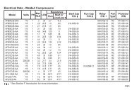
2. DESCRIPTION OF THE PRODUCTS<strong>pCO</strong> Sistema2.1 <strong>pCO</strong> 3 controllerRx-/Tx-Rx+/Tx+GNDC1NO1NO2NO3C1C4NO4NO5NO6C4C7NO7C7NO8C8NC8C9NO9NO10NO1110C9NO12C12NC12NO13C13NC13GJ1111J11J12J13J14J15J16 J17 J18J9J10NO14C14NC14NO15J21C15NC15C16NO16NO17NO18J22C16J23J19J20G0J24 J2 J3 J4 J5 J7J6+VtermGND+5 VREFB1B2B3GND+VDCB4BC4B5BC5VGVG0Y1Y2Y3Y4ID1ID2ID3ID4ID5ID6ID7ID8IDC1B6B7B8GNDID9ID10ID11ID12IDC9ID13HID13IDC13ID14ID14HJ83154521467478865711129E-E+GND1316input: 24 V / ; 50 to 60 Hzmax. p ower: 40 VA/15Wfield cardserial cardID15HID15IDC15ID16ID16HY5Y6B9BC9B10BC10ID17ID18IDC17C14NO14NO15NO16C14C17NO17NO18NO19NO20C17E-E+GNDJ21 J22 J23C14NC14NC15NC16C14C17NC17NC18NC19NC20C17E-E+GNDJ21 J22 J231111512C2112NO21J19NO22NO23NO24C21C25NO25J20NO26NO27NO28NO29C25C21NC21J19NC22NC23NC24C21C25J20NC25NC26NC27C25B9J25B10BC97Fig. 2.aKey:1. power supply connector [G (+), G0 (-)];2. yellow power LED <strong>and</strong> 3 status LEDs (see paragraph 6.3);3. additional power supply for the terminal <strong>and</strong> 0 to 5 V ratiometric probes;4. universal analogue inputs: NTC, 0 to 1 V, 0 to 5 V ratiometric, 0 to 10 V, 0 to 20 mA, 4 to 20 mA;5. passive analogue inputs: NTC, PT1000, ON/OFF;6. 0 to 10 V analogue outputs;7. 24 Vac/Vdc digital inputs;8. 230 Vac or 24 Vac/Vdc digital inputs;9. connector for the display panel (external panel with direct signals);10. connector for all st<strong>and</strong>ard <strong>pCO</strong> series terminals <strong>and</strong> for downloading the application program;11. relay digital outputs;12. connector for connection to the I/O expansion board;13. pLAN network connector;14. cover for inserting the supervisor <strong>and</strong> telemaintenance option;15. cover for inserting the field card option;16. Built-In terminal (LCD, buttons <strong>and</strong> LEDs).7Code: +030220336 - rel. 1.3 - 24/06/09 8
2.1.1 Meaning of the <strong>pCO</strong> 3 inputs/outputsConnector Signal DescriptionJ1-1 G +24 Vdc or 24 Vac power supplyJ1-2 G0 power supply referenceJ2-1 B1 universal analogue input 1 (NTC, 0 to 1 V, 0 to 10 V, 0 to 20 mA, 4 to 20 mA)J2-2 B2 universal analogue input 2 (NTC, 0 to 1 V, 0 to 10 V, 0 to 20 mA, 4 to 20 mA)J2-3 B3 universal analogue input 3 (NTC, 0 to 1 V, 0 to 10 V, 0 to 20 mA, 4 to 20 mA)J2-4 GND common for analogue inputsJ2-5 +VDC 21 Vdc power supply for active probes (maximum current 200 mA)J3-1 B4 passive analogue input 4 (NTC, PT1000, ON/OFF)J3-2 BC4 common for analogue input 4J3-3 B5 passive analogue input 5 (NTC, PT1000, ON/OFF)J3-4 BC5 common for analogue input 5J4-1 VG power to optically-isolated analogue output, 24 Vac/VdcJ4-2 VG0 power to optically-isolated analogue output, 0 Vac/VdcJ4-3 Y1 analogue output no. 1, 0 to 10 VJ4-4 Y2 analogue output no. 2, 0 to 10 VJ4-5 Y3 analogue output no. 3, 0 to 10 VJ4-6 Y4 analogue output no. 4, 0 to 10 VJ5-1 ID1 digital input no. 1, 24 Vac/VdcJ5-2 ID2 digital input no. 2, 24 Vac/VdcJ5-3 ID3 digital input no. 3, 24 Vac/VdcJ5-4 ID4 digital input no. 4, 24 Vac/VdcJ5-5 ID5 digital input no. 5, 24 Vac/VdcJ5-6 ID6 digital input no. 6, 24 Vac/VdcJ5-7 ID7 digital input no. 7, 24 Vac/VdcJ5-8 ID8 digital input no. 8, 24 Vac/VdcJ5-9 IDC1 common for digital inputs from 1 to 8 (negative pole for DC power supply)J6-1 B6 universal analogue input 6 (NTC, 0 to 1 V, 0 to 10 V, 0 to 20 mA, 4 to 20 mA)J6-2 B7 universal analogue input 7 (NTC, 0 to 1 V, 0 to 10 V, 0 to 20 mA, 4 to 20 mA)J6-3 B8 universal analogue input 8 (NTC, 0 to 1 V, 0 to 10 V, 0 to 20 mA, 4 to 20 mA)J6-4 GND common for analogue inputsJ7-1 ID9 digital input no. 9, 24 Vac/VdcJ7-2 ID10 digital input no. 10, 24 Vac/VdcJ7-3 ID11 digital input no. 11, 24 Vac/VdcJ7-4 ID12 digital input no. 12, 24 Vac/VdcJ7-5 IDC9 common for digital inputs from 9 to 12 (negative pole for DC power supply)J8-1 ID13H digital input 13, 230 VacJ8-2 ID13 digital input 13, 24 Vac/VdcJ8-3 IDC13 common for digital inputs 13 <strong>and</strong> 14 (negative pole for DC power supply)J8-4 ID14 digital input 14, 24 Vac/VdcJ8-5 ID14H digital input 14, 230 VacJ98-pin telephone connector for connection to a display panelJ106-pin telephone connector for connection to the st<strong>and</strong>ard user terminalJ11-1 RX-/TX- RX-/TX- connector for RS485 connection to the pLAN networkJ11-2 RX+/TX+ RX+/TX+ connector for RS485 connection to the pLAN networkJ11-3 GND GND connector for RS485 connection to the pLAN networkJ12-1 C1 common for relays: 1, 2, 3J12-2 NO1 normally open contact, relay no. 1J12-3 NO2 normally open contact, relay no. 2J12-4 NO3 normally open contact, relay no. 3J12-5 C1 common for relays: 1, 2, 3J13-1 C4 common for relays: 4, 5, 6J13-2 NO4 normally open contact, relay no. 4J13-3 NO5 normally open contact, relay no. 5J13-4 NO6 normally open contact, relay no. 6J13-5 C4 common for relays: 4, 5, 6J14-1 C7 common for relay no. 7<strong>pCO</strong> SistemaCode: +030220336 - rel. 1.3 - 24/06/09 9
Connector Signal DescriptionJ14-2 NO7 normally open contact, relay no. 7J14-3 C7 common for relay no. 7J15-1 NO8 normally open contact, relay no. 8J15-2 C8 common for relay no. 8J15-3 NC8 normally closed contact, relay no. 8J16-1 C9 common for relays: 9, 10, 11J16-2 NO9 normally open contact, relay no. 9J16-3 NO10 normally open contact, relay no. 10J16-4 NO11 normally open contact, relay no. 11J16-5 C9 common for relays: 9, 10, 11J17-1 NO12 normally open contact, relay no. 12J17-2 C12 common for relay no. 12J17-3 NC12 normally closed contact, relay no. 12J18-1 NO13 normally open contact, relay no. 13J18-2 C13 common for relay no. 13J18-3 NC13 normally closed contact, relay no. 13J19-1 ID15H digital input 15, 230 VacJ19-2 ID15 digital input 15, 24 Vac/VdcJ19-3 IDC15 common for digital inputs 15 <strong>and</strong> 16 (negative pole for DC power supply)J19-4 ID16 digital input 16, 24 Vac/VdcJ19-5 ID16H digital input 16, 230 VacJ20-1 Y5 analogue output no. 5 to 0 to 10 VJ20-2 Y6 analogue output no. 6 to 0 to 10 VJ20-3 B9 passive analogue input 9 (NTC, PT1000, ON/OFF)J20-4 BC9 common for analogue input 9J20-5 B10 passive analogue input 10 (NTC, PT1000, ON/OFF)J20-6 BC10 common for analogue input 10J20-7 ID17 digital input no. 17, 24 Vac/VdcJ20-8 ID18 digital input no. 18, 24 Vac/VdcJ20-9 IDC17 common for digital inputs 17 <strong>and</strong> 18 (negative pole for DC power supply)J21-1 NO14 normally open contact, relay no. 14J21-2 C14 common for relay no. 14J21-3 NC14 normally closed contact, relay no. 14J21-4 NO15 normally open contact, relay no. 15J21-5 C15 common for relay no. 15J21-6 NC15 normally closed contact, relay no. 15J22-1 C16 common for relays: 16, 17, 18J22-2 NO16 normally open contact no. 16J22-3 NO17 normally open contact no. 17J22-4 NO18 normally open contact no. 18J22-5 C16 common for relays: 16, 17, 18J23-1 E- E- terminal for RS485 connection to the I/O expansion modulesJ23-2 E+ E+ terminal for RS485 connection to the I/O expansion modulesJ23-3 GND GND terminal for RS485 connection to the I/O expansion modulesJ24-1 +V term additional power supply terminal for AriaJ24-2 GND power supply commonJ24-3 +5 Vref power supply for 0/5 V ratiometric probesNote: J19, J20, J21, J22 <strong>and</strong> J23 correspond to the “LARGE” model.<strong>pCO</strong> SistemaCode: +030220336 - rel. 1.3 - 24/06/09 10
2.2 <strong>pCO</strong> 3 technical specifications<strong>pCO</strong> Sistema• <strong>pCO</strong> 3 analogue inputsAnalogue conversion10-bit A/D converter embedded in CPUMaximum numberSMALL MEDIUM <strong>and</strong> EXTRALARGE NO LARGE <strong>and</strong> EXTRALARGE NC5 8 10TypeUniversal: 6 (inputs B1, B2, B3, B6, B7, B8)-CAREL NTC (-50T90°C; R/T 10kΩ±1% at 25°C) or HT NTC (0T150°C)-Voltage: 0 to 1 Vdc, 0 to 5 Vdc ratiometric or 0 to 10 Vdc-Current: 0 to 20 mA or 4 to 20 mA. Input resistance: 100ΩCan be selected via software.Minimum normally-open voltage-free digital inputPassive: 4 (inputs B4, B5, B9, B10)-CAREL NTC (-50T90°C; R/T 10kΩ ±1% at 25°C) or HT NTC (0T150°C)-PT1000 (-100T200°C; R/T 1kΩ at 0°C) or digital input from voltage-free contactCan be selected via software.Normally open (open-closed-open)250 msdetection time Normally closed (closed-open-closed) 250 msNTC input precision± 0.5°CPT1000 input precision ± 1°C0-1V input precision ± 3 mV0-10V input precision ± 30 mV0-5V input precision ± 15 mV0-20 mA input precision ± 0.06 mAWarning: for the power supply of any active probes, the 21 Vdc available at the +Vdc terminal (J2) can be used. The maximum current is 150 mA, protected againstshort-circuits. To supply the 0/5V ratiometric probes, use the 5V available at the +5Vref (terminal J24). The maximum current is 60 mA.• <strong>pCO</strong> 3 digital inputsTypeMaximum numberoptically-isolatedno. optically-isolated inputs at 24 Vac50/60 Hz or 24Vdcno. optically-isolated inputs at 24Vac/Vdc or 230 Vac 50/60 HzTotalMinimum digital input pulse detection timePower supply to the inputsClassification of the measurement circuits(IEC EN 61010-1)SMALL 8 None 8MEDIUM/EXTRALARGE 12 2 14LARGE 14 2+2 18Normally open (open-closed-open)200 msNormally closed (closed-open-closed)400 ms230 Vac or 24 Vac (50/60 Hz) +10/-15%External24Vdc +10/-20%Category 1 24 Vac/VdcCategory 3 230 VacWarnings:• the two 230 Vac or 24 Vac/Vdc inputs at terminals J8 (ID13, ID14) or J19 (ID15, ID16) have the same common pole <strong>and</strong> consequently both must be set to thesame voltage (230 Vac or 24 Vac/Vdc). There is primary insulation between the two inputs;• for DC voltage inputs (24Vdc) connect the negative pole to the common terminal.• <strong>pCO</strong> 3 analogue outputsTypeoptically-isolatedMaximum number4 outputs (Y1-Y4), 0 to 10 Vdc SMALL, MEDIUM <strong>and</strong> EXTRALARGE6 outputs (Y1-Y6), 0 to 10 Vdc LARGEPower supply external 24 Vac/VdcPrecisionoutputs Y1-Y4± 2% of full scaleoutputs Y5-Y6-2/+5% of full scaleResolution8 bitSettling timeoutputs Y1-Y42soutputs Y5-Y62s or 15s can be selected via softwareMaximum load1 kΩ (10mA)Code: +030220336 - rel. 1.3 - 24/06/09 11
<strong>pCO</strong> Sistema• <strong>pCO</strong> 3 digital outputsThe relay outputs have different features depending on the model of <strong>pCO</strong> 3 .The outputs can be divided into groups. There is double insulation between the groups (cells in the table) <strong>and</strong> consequently these may haveInsulation distance different voltages. There is also double insulation between each terminal of the digital outputs <strong>and</strong> the rest of the controller. The relaysbelonging to the same group (individual cells in the table) have basic insulation <strong>and</strong> therefore must have the same power supply (24 Vac or230 Vac).VersionReference of the relays with the same insulationGroup 1 Group 2 Group 3 Group 4 Group 5 Group 6 Group 7SMALL 1 to 7 8Type of relay Type A Type AMEDIUM 1 to 7 8 9 to 13Makeup of the Type of relay Type A Type A Type Agroups LARGE 1 to 7 8 9 to 13 14 to 18Type of relay Type A Type A Type A Type AEXTRALARGE NO 1 to 7 8 9 to 13 14 to 16 17 to 20 21 to 24 25 to 29Type of relay Type A Type A Type A Type B Type B Type B Type BEXTRALARGE NC 1 to 7 8 9 to 13 14 to 16 17 to 20 21 to 24 25 to 27Type of relay Type A Type A Type A Type C Type C Type C Type CNumber of 1: SMALL (output 8); 3:MEDIUM <strong>and</strong> EXTRALARGE NO/NC (outputs 8.12 <strong>and</strong> 13);changeover contacts 5: LARGE (outputs 8, 12, 13, 14 <strong>and</strong> 15)Relay ratings SPDT, 2000 VA, 250 Vac, 8 A resistiveRelay type A2.5 A resistive, 2 A FLA, 12 A LRA, 250 Vac, C300 pilot duty (30,000UL873<strong>pCO</strong> 3 approvalcycles)EN 60730-12 A resistive, 2 A inductive, cosϕ=0.6, 2(2)A (100,000 cycles)Relay ratings SPDT, 1250 VA, 250 Vac, 5 A resistiveSwitchable powerRelay type BUL8731 A resistive, 1 A FLA, 6 A LRA, 250 Vac, D300 pilot duty (30,000 cycles)<strong>pCO</strong> 3 approvalEN 60730-11 A resistive, 1 A inductive, cosϕ=0.6, 1(1)A (100,000 cycles)Relay ratings SPDT, 1250 VA, 250 Vac, 5 A resistiveRelay type CUL8731 A resistive, 1 A FLA, 6 A LRA, 250 Vac, D300 pilot duty (30,000 cycles)<strong>pCO</strong> 3 approvalEN 60730-11 A resistive, 1 A inductive, cosϕ=0.6, 1(1)A (100,000 cycles)Maximum numberof SSR outputs1: SMALL (output 7); 2:MEDIUM <strong>and</strong> EXTRALARGE NO/NC (outputs 7 <strong>and</strong> 12); 3: LARGE (outputs 7, 12 <strong>and</strong> 14)Electrical specifications: working voltage 24 Vac/Vdc, maximum switchable output 10 WattsWarnings:• The groups that the digital outputs are divided into have two common pole terminals to simplify wiring;• make sure that the current running through the common terminals does not exceed the rated current of an individual terminal, that is, 8 A.• <strong>pCO</strong> 3 mechanical specificationsMechanical dimensionsSMALL 13 DIN modules 110 x 227.5 x 60mmMEDIUM, LARGE, EXTRALARGE 18 DIN modules 110 x 315 x 60mmPlastic containerAssembly Fitted on DIN rail as per DIN 43880 <strong>and</strong> IEC EN 50022MaterialTechnopolymerFlame retardancy V0 (UL94) <strong>and</strong> 960°C (IEC 695)Ball pressure test 125°CResistance to creeping current≥ 250 VColourGrey RAL7035• <strong>pCO</strong> 3 other featuresOperating conditions-25T70°C, 90% RH non-condensingStorage conditions-40T70°C, 90% RH non-condensingIndex of protectionIP20, IP40 on the front panel onlyEnvironmental pollution 2Class according to protection against electric shockto be integrated into Class 1 <strong>and</strong>/or 2 appliancesPTI of the insulating materials250 VPeriod of stress across the insulating partslongType of action1CType of disconnection or microswitchingmicroswitching, for all relay outputsCategory of resistance to heat <strong>and</strong> fireCategory DImmunity against voltage surges Category 1Ageing characteristics (operating hours) 80,000No. of automatic operating cycles 100,000 (EN 60730-1); 30,000 (UL 873)Software class <strong>and</strong> structureClass ACategory of immunity to voltage surges (IEC EN 61000-4-5) Category 3ClockError at 25 °CError in the temperature range –10T60 °CAgeingBattery durationRecharge time±5.3 min/year±27 min/year< ± 5ppm (±2.7min/year)typically 6 months (maximum 8 months)typically 5 hours (
• <strong>pCO</strong> 3 electrical specificationsPower supply 24 Vac +10/-15% 50/60 Hz <strong>and</strong> 28 to 36Vdc +10/-20%Maximum current with terminal connected40 VA (Vac) / 15 W (Vdc)Type of insulation of the power supply from the rest of the controller -Terminal blockwith male/female plug-in connectors (250 Vac max, 8 A max)Cable cross-section min 0.5 mm 2 – max 2.5 mm 2CPUH8S2320, 16 bit, 24 MHzProgram memory (FLASH MEMORY)2+2 Mbyte (Dual Bank) 16 bitData memory (RAM)512 Kbyte, 16 bitT memory, buffer (EEPROM)13 KbyteP memory, parameters (EEPROM)32 Kbyte, not available to the pLAN networkWorking cycle duration (application of average complexity)0.2 sClock with batteryst<strong>and</strong>ard<strong>pCO</strong> Sistema<strong>pCO</strong> 3 dimensions (in mm)• MEDIUM, LARGE, EXTRALARGE N.O. <strong>and</strong> N.C.: 18 DIN modules4445 110315 60Fig. 2.b• SMALL: 13 DIN modules4445 110227,5Fig. 2.c60Product certification:• IEC EN 50155 st<strong>and</strong>ard: “Railway applications • Electronic equipment used on rolling stock”;• UL 873 <strong>and</strong> C22.2 No. 24-93: “Temperature-Indicating <strong>and</strong> -Regulating Equipment”;• EC regulations 37/2005 of 12 January 2005; in particular, if the electronic controller is fitted with st<strong>and</strong>ard <strong>Carel</strong> NTC probes, it is compliant with st<strong>and</strong>ardEN13485 on “Thermometers for measuring the air temperature in applications on units for the conservation <strong>and</strong> sale of refrigerated, frozen <strong>and</strong> deep-frozenfood <strong>and</strong> ice cream”.Code: +030220336 - rel. 1.3 - 24/06/09 13
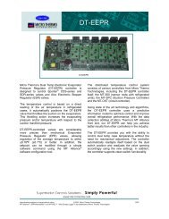
2.3 <strong>pCO</strong> 1 controller<strong>pCO</strong> SistemaGG0B1B2B3B4+VDCB5GNDB6GNDVGVG0Y1Y2Y3Y4ID1ID2ID3ID4ID5ID6ID7ID8IDC1B7GNDB8GNDID9Rx-/Tx-Rx+/Tx+GNDC1NO1NO2NO3C1C4J11NO4NO5NO6C4C7NO7C7J9NO8C8NC8C9NO9NO10NO11C9NO13C13NC13Programming KeyJ12J13J14J15J16J17J18Clock cardAnalog SelectionSerial CardFuse12346785ID10ID11ID12IDC9ID13HID13IDC13ID14ID14H171516J1J10+5V RifGND+V TermJ21011J3J412J5J6J7J8891413Fig.. 2.dKey:1. power supply connector [G (+), G0 (-)]2. 250 Vac, 2 A slow-blow fuse (T2 A)3. universal analogue inputs: NTC, 0/1V, 0/5 V, 0/20 mA, 4/20 mA4. passive analogue inputs: NTC <strong>and</strong> ON/OFF5. passive analogue inputs: NTC6. yellow power LED <strong>and</strong> 3 status LEDs (see paragraph 6.3)7. 0 to 10 V analogue outputs <strong>and</strong> PWM outputs8. 24 Vac/Vdc digital inputs9. 230 Vac or 24 Vac/Vdc digital inputs10. connector with Vref for power supply to 5V ratiometric probe <strong>and</strong> V term for power supply to Aria terminal11. connector for all st<strong>and</strong>ard <strong>pCO</strong>* series terminals <strong>and</strong> for downloading the application program12. pLAN network connector13. programming key connector14. relay digital outputs15. port for selecting the type of analogue inputs16. cover for inserting the optional supervisor <strong>and</strong> telemaintenance board17. cover for inserting the clock board2.3.1 Meaning of the <strong>pCO</strong> 1 inputs/outputsConnector Signal DescriptionJ1-1 G +24 Vdc or 24 Vac power supplyJ1-2 G0 power supply referenceJ2-1 B1 universal analogue input 1 (NTC, 0/1V, 0/5 V, 0/20 mA, 4/20 mA)J2-2 B2 universal analogue input 2 (NTC, 0/1V, 0/5 V, 0/20 mA, 4/20 mA)J2-3 B3 universal analogue input 3 (NTC, 0/1V, 0/5 V, 0/20 mA, 4/20 mA)J2-4 B4 universal analogue input 4 (NTC, 0/1V, 0/5 V, 0/20 mA, 4/20 mA)J2-5 +VDC 24 Vdc power supply for active probes (maximum current 100 mA)J3-1 B5 passive analogue input 5 (NTC, ON/OFF)J3-2 GND common for analogue input 5J3-3 B6 passive analogue input 6 (NTC, ON/OFF)J3-4 GND common for analogue input 6J4-1 VG power to optically-isolated analogue output, 24 Vac/VdcJ4-2 VG0 power to optically-isolated analogue output, 0 Vac/VdcJ4-3 Y1 analogue output no. 1, 0/10 VJ4-4 Y2 analogue output no. 2, 0/10 VJ4-5 Y3 analogue output no. 3, PWM (for phase cutting speed controllers)J4-6 Y4 analogue output no. 4, PWM (for phase cutting speed controllers)J5-1 ID1 digital input no. 1, 24 Vac/VdcCode: +030220336 - rel. 1.3 - 24/06/09 14
Connector Signal DescriptionJ5-2 ID2 digital input no. 2, 24 Vac/VdcJ5-3 ID3 digital input no. 3, 24 Vac/VdcJ5-4 ID4 digital input no. 4, 24 Vac/VdcJ5-5 ID5 digital input no. 5, 24 Vac/VdcJ5-6 ID6 digital input no. 6, 24 Vac/VdcJ5-7 ID7 digital input no. 7, 24 Vac/VdcJ5-8 ID8 digital input no. 8, 24 Vac/VdcJ5-9 IDC1 common for digital inputs from 1 to 8 (negative pole for DC power supply)J6-1 B7 passive analogue input 7 (NTC)J6-2 GND common for analogue input 7J6-3 B8 passive analogue input 8 (NTC)J6-4 GND common for analogue input 8J7-1 ID9 digital input no. 9, 24 Vac/VdcJ7-2 ID10 digital input no. 10, 24 Vac/VdcJ7-3 ID11 digital input no. 11, 24 Vac/VdcJ7-4 ID12 digital input no. 12, 24 Vac/VdcJ7-5 IDC9 common for digital inputs from 9 to 12 (negative pole for DC power supply)J8-1 ID13H digital input 13, 230 VacJ8-2 ID13 digital input 13, 24 Vac/VdcJ8-3 IDC13 common for digital inputs 13 <strong>and</strong> 14 (negative pole for DC power supply)J8-4 ID14 digital input 14, 24 Vac/VdcJ8-5 ID14H digital input 14, 230 VacJ9-1 + 5 V ref power supply for 0/5 V ratiometric probesJ9-2 GND power supply commonJ93 + Vterm additional power supply terminal for AriaJ106-pin telephone connector for connection to the st<strong>and</strong>ard user terminalJ11-1 TX- RX-/TX- connector for RS485 connection to the pLAN networkJ11-2 TX+ RX+/TX+ connector for RS485 connection to the pLAN networkJ11-3 GND GND connector for RS485 connection to the pLAN networkJ12-1 C1 common for relays: 1, 2, 3J12-2 NO1 normally open contact, relay no. 1J12-3 NO2 normally open contact, relay no. 2J12-4 NO3 normally open contact, relay no. 3J12-5 C1 common for relays: 1, 2, 3J13-1 C4 common for relays: 4, 5, 6J13-2 NO4 normally open contact, relay no. 4J13-3 NO5 normally open contact, relay no. 5J13-4 NO6 normally open contact, relay no. 6J13-5 C4 common for relays: 4, 5, 6J14-1 C7 common for relay no. 7J14-2 NO7 normally open contact, relay no. 7J14-3 C7 common for relay no. 7J15-1 NO8 normally open contact, relay no. 8J15-2 C8 common for relay no. 8J15-3 NC8 normally closed contact, relay no. 8J16-1 C9 common for relays: 9, 10, 11J16-2 NO9 normally open contact, relay no. 9J16-3 NO10 normally open contact, relay no. 10J16-4 NO11 normally open contact, relay no. 11J16-5 C9 common for relays: 9, 10, 11J17-1 NO12 normally open contact, relay no. 12J17-2 C12 common for relay no. 12J17-3 NC12 normally closed contact, relay no. 12J18-1 NO13 normally open contact, relay no. 13J18-2 C13 common for relay no. 13J18-3 NC13 normally closed contact, relay no. 13<strong>pCO</strong> SistemaCode: +030220336 - rel. 1.3 - 24/06/09 15
2.4 <strong>pCO</strong> 1 technical specifications<strong>pCO</strong> Sistema• <strong>pCO</strong> 1 analogue inputsAnalogue conversion10-bit A/D converter embedded in CPUMaximum numberSMALLMEDIUM6 8TypeUniversal: 4 (inputs B1, B2, B3, B4)-CAREL NTC (-50T90°C; R/T 10kΩ±1% at 25°C) HT NTC (0T150°C)-Voltage 0 to 1 Vdc, 0 to 5 Vdc ratiometric-Current 0 to 20 mA or 4 to 20 mA. Input resistance: 100Ω.Can be selected via dipswitchPassive: 4 (inputs B5, B6, B7, B8)-CAREL NTC (-50T90°C; R/T 10kΩ±1% at 25°C) HT NTC (0T150°C)-Digital input (inputs B5, B6) from voltage-free contactCan be selected via dipswitchMinimum normally-open voltage-free digital input Normally open (open-closed-open)250 msdetection time Normally closed (closed-open-closed) 250 msTime constant for each input2sInput precision NTC± 0.5°CInput precision 0-1V± 3 mVInput precision 0-5V± 15 mVInput precision 0-20 mA± 0.06 mAWarning: for the power supply of any active probes, the 24 Vdc available at the +Vdc terminal (J2) can be used. The maximum current is 100 mA, protected againstshort-circuits. To supply the 0/5V ratiometric probes, use the 5V available at the +5Vref (terminal J9). The maximum current is 60 mA.• <strong>pCO</strong> 1 digital inputsTypeMaximum numberMinimum digital input pulse detection timePower supply to the inputsoptically-isolatedno. optically-isolated inputsat 24 Vac 50/60 Hz or 24Vdcno. optically-isolated inputsat 24 Vac/Vdc or 230 Vac50/60 HzSMALL 8 None 8MEDIUM 12 2 14Normally open (open-closed-open)200 msNormally closed (closed-open-closed)400 ms230 Vac or 24 Vac (50/60 Hz) +10/-15%external24Vdc +10/-20%TotalWarnings:• the two 230 Vac or 24 Vac/Vdc inputs at terminals J8 have the same common pole <strong>and</strong> consequently both must be set to the same voltage (230 Vac or 24Vac/Vdc). There is primary insulation between the two inputs;• for DC voltage inputs (24Vdc) connect the negative pole to the common terminal.• <strong>pCO</strong> 1 analogue outputsTypeoptically-isolatedMaximum number2 outputs (Y1-Y2), 0 to 10 Vdc <strong>and</strong>2 outputs (Y3-Y4) PWM with 5 V pulse of programmable SMALL, MEDIUMdurationPower supply external 24 Vac/VdcPrecision outputs Y1-Y2 ± 1% of full scaleResolution 0.5%Settling time outputs Y1-Y2 2sMaximum load1 kΩ (10mA) for 0 to 10 Vdc <strong>and</strong> 470Ω (10mA) for PWMCode: +030220336 - rel. 1.3 - 24/06/09 16
<strong>pCO</strong> Sistema• <strong>pCO</strong> 1 digital outputsThe relay outputs have different features depending on the model of <strong>pCO</strong> 1Insulation distanceThe outputs can be divided into groups. There is double insulation between the groups (cells in the table) <strong>and</strong> consequently these may havedifferent voltages. There is also double insulation between each terminal of the digital outputs <strong>and</strong> the rest of the controller. The relays belonging tothe same group (individual cells in the table) have basic insulation <strong>and</strong> therefore must have the same power supply (24 Vac or 230 Vac).VersionReference of the relays with the same insulationGroup 1 Group 2 Group 3 Group 4 Group 5 Group 6 Group 7Makeup of the SMALL 1 to 3 4 to 6 7 8groups Type of relay Type A Type A Type A Type AMEDIUM 1 to 3 4 to 6 7 8 9 to 11 12 13Number ofchangeover contactsSwitchable powerMaximum numberof SSR outputsType of relay Type A Type A Type A Type A Type A Type A Type A1: SMALL (output 8); 3: MEDIUM (outputs 8, 12 <strong>and</strong> 13);Relay ratingsSPDT, 2000 VA, 250 Vac, 8 A resistiveRelay type AUL8732.5 A resistive, 2 A FLA, 12 A LRA, 250 Vac, C300 pilot duty (30,000 cycles)<strong>pCO</strong> 1 approvalEN 60730-1 2 A resistive, 2 A inductive, cosϕ=0.6, 2(2)A (100,000 cycles)2: SMALL (output 7 <strong>and</strong> 8); 4: MEDIUM (outputs 7, 8, 12 <strong>and</strong> 13);Electrical specifications: working voltage 24 Vac/Vdc, maximum switchable output 10 WattsWarnings:• The groups that the digital outputs are divided into have two common pole terminals to simplify wiring.• Make sure that the current running through the common terminals does not exceed the rated current of an individual terminal, that is, 8 A• <strong>pCO</strong> 1 mechanical specificationsMechanical dimensionsSMALL 13 DIN modules 110 x 227.5 x 60mmMEDIUM 18 DIN modules 110 x 315 x 60mmPlastic containerAssembly Fitted on DIN rail as per DIN 43880 <strong>and</strong> IEC EN 50022MaterialtechnopolymerFlame retardancy V0 (UL94) <strong>and</strong> 960°C (IEC 695)Ball pressure test 125°CResistance to creeping current≥250 VColourGrey RAL7035• <strong>pCO</strong> 1 other featuresOperating conditions-10T60°C, 90% RH non-condensingStorage conditions-20T70°C, 90% RH non-condensingIndex of protectionIP20, IP40 on the front panel onlyEnvironmental pollution 2Class according to protection against electric shockto be integrated into Class 1 <strong>and</strong>/or 2 appliancesPTI of the insulating materials250 VPeriod of stress across the insulating partslongType of action1CType of disconnection or microswitchingmicroswitching, for all relay outputsCategory of resistance to heat <strong>and</strong> fireCategory DImmunity against voltage surges Category 1Ageing characteristics (operating hours) 80,000No. of automatic operating cycles 100,000 (EN 60730-1); 30,000 (UL 873)Software class <strong>and</strong> structureClass ACategory of immunity to voltage surges (IEC EN 61000-4-5) Category 3ClockError at 25 °CError in the temperature range –10T60 °CAgeingBattery durationRecharge time±5.3 min/year±27 min/year< ± 5ppm (±2.7min/year)typically 6 months (maximum 8 months)typically 5 hours (
Dipswitches for selecting the type of probe<strong>pCO</strong> SistemaB1 B2 B3 B4 B5 B61 2 3 4 5 61 2 3 4 5 6 1 2ONOFF1 2 3 4 5 6 1 2 3 4 5 61 2 3 4 5 6 1 2 3 4 5 6NTCInput B1, B2, B3, B41 2 3 4 5 6 1 2 3 4 5 61 2 3 4 5 6 1 2 3 4 5 6Esempio/ ExampleB1 B2 B3 B4 B5 B6ONOFFNTC NTC digital inputInput B5, B6ONOFFdigitalinputInputdigital inputNTCONOFFNTC<strong>pCO</strong> 1 dimensions (in mm.)• MEDIUM 18 DIN modules44Fig. 2.e• SMALL 18 DIN modules44Fig.. 2.fCode: +030220336 - rel. 1.3 - 24/06/09 18
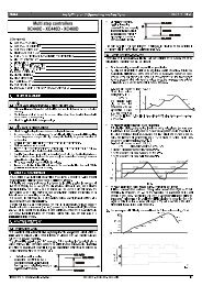
2.5 <strong>pCO</strong> xs boardJ1 J55 6 7 8 9 10 11RXTX-RXTX+GNDJ6xsJ7J2TLANGNDJ8CLOCKCARD12C1NO1NO2NO3C4NO4NO5C5NC514built-in terminal15J3J9J10SERIALCARD 13J4<strong>pCO</strong> SistemaKey:1 Power supply connector [G (+), G0 (-)], 24 Vac or 24 to 48 Vdc;2 Input (24 Vac) for phase control <strong>and</strong> NTC, 0/1 V, 0/5 V, 0/20 mA, 4/20 mAanalogue inputs, +5Vref for power supply to 5V ratiometric probe <strong>and</strong>+24 Vdc power to active probes;3 0 to 10 V analogue outputs <strong>and</strong> PWM output;4 Digital inputs with voltage-free contact;5 Connector for all st<strong>and</strong>ard <strong>pCO</strong>* series terminals <strong>and</strong> for downloading theapplication program;6 pLAN network connector;7 tLAN terminal connector;8 tLAN or MP-Bus network connector;9 Relay digital outputs with one common;10 Relay/SSR digital output;11 Digital output for alarm relay with changeover contact/SSR;12 Yellow power LED <strong>and</strong> 3 status LEDs(see paragraph 6.3)13 Cover for inserting the supervisor <strong>and</strong> telemaintenance option14 Cover for inserting the clock board;15 Built-In terminal.GG0SYNCB1B2B3B4GND+5VREF+24VDCY1Y2Y3GNDID1ID2ID3ID4ID5ID6IDC1J11123 4Fig. 2.f2.5.1 Meaning of the <strong>pCO</strong> xs board inputs/outputsConnector Signal DescriptionJ1-1 G 24 Vac or 24 to 48 Vdc power supplyJ1-2 G0 power supply referenceJ2-1 SYNC synchronicity input for phase control (G0 is the reference)J2-2 B1 universal analogue input 1 (NTC, 0/1V, 0/5 V, 0/20 mA, 4/20 mA)J2-3 B2 universal analogue input 2 (NTC, 0/1V, 0/5 V, 0/20 mA, 4/20 mA)J2-4 B3 universal analogue input 3 (NTC, 0/5 V)J2-5 B4 universal analogue input 4 (NTC, 0/5 V)J2-6 GND reference for the analogue inputsJ2-7 +5VREF power supply for 0/5 V ratiometric probesJ2-8 +24VDC 24 Vdc power supply for active probesJ3-1 Y1 analogue output no. 1, 0/10 VJ3-2 Y2 analogue output no. 2, 0/10 VJ3-3 Y3 analogue output no. 3, PWM (for phase cutting speed controllers)J3-4 GND reference for analogue outputJ4-1 ID1 digital input no. 1J4-2 ID2 digital input no. 2J4-3 ID3 digital input no. 3J4-4 ID4 digital input no. 4J4-5 ID5 digital input no. 5J4-6 ID6 digital input no. 6J4-7 IDC1 common for digital inputs from 1 to 6J56-pin telephone connector for connection to the st<strong>and</strong>ard user terminalJ6-1 RX-/TX- RX-/TX- connector for RS485 connection to the pLAN networkJ6-2 RX+/TX+ RX+/TX+ connector for RS485 connection to the pLAN networkJ6-3 GND reference for RS485 connection to the pLAN networkJ7tLAN terminal connectorJ8-1 TLAN connector to the tLAN networkJ8-2 GND reference for connection to the tLAN networkJ9-1 C1 common for relays: 1, 2, 3J9-2 NO1 normally open contact, relay no. 1J9-3 NO2 normally open contact, relay no. 2J9-4 NO3 normally open contact, relay no. 3J10-1 C4 common for relays: 4J10-2 NO4 normally open contact, relay no. 4J11-1 NO5 normally open contact, relay no. 5J11-2 C5 common for relays: 5J11-3 NC5 normally closed contact, relay no. 5Tab. 2.eCode: +030220336 - rel. 1.3 - 24/06/09 19
2.6 <strong>pCO</strong> xs technical specifications<strong>pCO</strong> Sistema• <strong>pCO</strong> XS analogue inputsAnalogue conversion10-bit A/D converter embedded in CPUMaximum number 4Type Universal: 2 (inputs B1, B2)-CAREL NTC (-50T90°C; R/T 10kΩ±1% at 25°C)-Voltage 0 to 1 Vdc, 0 to 5 Vdc ratiometric;-Current 0 to 20 mA or 4 to 20 mA. Input resistance: 100ΩCan be selected via softwareUniversal: 2 (inputs B3, B4)-CAREL NTC (-50T90°C; R/T 10kΩ±1% at 25°C)-Voltage 0 to 5 Vdc ratiometricCan be selected via softwareTime constant for each input1 sInput precision NTC± 0.5°CInput precision 0-1V± 3 mVInput precision 0-5V± 15 mVInput precision 0-20 mA± 0.06 mAWarning: for the power supply of any active probes, the 24 Vdc available at the +Vdc terminal (J2) can be used. The maximum current is 80 mA, protected againstshort-circuits. To supply the 0/5V ratiometric probes, use the 5V available at the +5Vref (terminal J2). The maximum current is 60 mA.• <strong>pCO</strong> XS digital inputsTypeMaximum numberMinimum digital input pulse detection timePower supply to the inputsNot optically-isolated with voltage-free contactno. optically-isolated inputs at 24 Vac 50/60 Hzor 24Vdcno. optically-isolated inputs at 24 Vac/Vdc or 230Vac 50/60 HzTotal6 None 6Normally open (open-closed-open)150 msNormally closed (closed-open-closed)400 msinternal• <strong>pCO</strong> XS analogue outputsTypeNot optically-isolatedMaximum number2 outputs (Y1 <strong>and</strong> Y2), 0 to 10 Vdc <strong>and</strong>1 output (Y3), PWM with 5V pulse of programmable durationPower supplyinternalPrecision outputs Y1-Y2 ± 3% of full scaleResolution8 bitSettling time outputs Y1-Y2 2sMaximum load1 kΩ (10 mA) for 0 to 10 Vdc <strong>and</strong> 470Ω (10 mA) for PWMNote: the synchronicity for the PWM output derives from the SYNC <strong>and</strong> G0 inputs. The PWM output (Y3) can become a pulse modulation output (duration of thepulse proportional to the analogue value) by setting the software. The PWM may be in synchronicity with the SYNC signal or have a fixed cycle duration of 2 ms.• <strong>pCO</strong> XS digital outputsInsulation distanceMakeup of thegroupsNumber ofchangeover contactsThe relay outputs have different features depending on the model of PCO XS .The outputs can be divided into groups. There is double insulation between the groups (cells in the table) <strong>and</strong> consequently these may havedifferent voltages. There is also double insulation between each terminal of the digital outputs <strong>and</strong> the rest of the controller. The relaysbelonging to the same group (individual cells in the table) have basic insulation <strong>and</strong> therefore can have the same power supply (24 Vac or 230Vac).VersionReference of the relays with the same insulationGroup 1 Group 2 Group 3- 1 to 3 4 5Type of relay Type A Type A Type A1: output 5Relay ratings SPDT, 2000 VA, 250 Vac, 8 A resistiveSwitchable power Relay type AUL8732.5 A resistive, 2 A FLA, 12 A LRA, 250 Vac, (30,000 cycles)<strong>pCO</strong> xs approvalEN 60730-1 2 A resistive, 2 A inductive, cosϕ=0.6, 2(2)A (100,000 cycles)Maximum number 2: outputs 4 <strong>and</strong> 5;of SSR outputs Electrical specifications: working voltage 24 Vac/Vdc, maximum switchable output 10 WattsWarnings:• the groups that the digital outputs are divided into have two common pole terminals to simplify wiring.• Make sure that the current running through the common terminals does not exceed the rated current of an individual terminal, that is, 8 A.Code: +030220336 - rel. 1.3 - 24/06/09 20
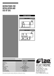
2.7 <strong>pCO</strong> C controller<strong>pCO</strong> Sistema1245151413GG0VG0VG1Y1Y0ID230ID24ID11R--------ID12RID24ID230NO11C11NC11--------NO10C10NC10--------NO9C9NC9NO8C8-------NO7C7-------NO6C6-------NO13C13J17J11J19J20J21J22J24J1J2J3J4J5J6B8+24VdcB7B6AVSSB5B4AVSSB3B2AVSSB1IDCM2ID10ID9ID8ID7ID6IDCM1ID5ID4ID3ID2ID1C1NO1-------C2NO2C3NO3-------C4NO4-------C5NO5-------C12NO12101112137<strong>pCO</strong> c I/O board36GNDRX/TX-RX/TX+98Fig. 2.hKey:1. Connector for 24 Vac power supply, 50/60 Hz, 15 VA, or 24 Vdc, 10 W.2. 250 Vac, 2 A slow-blow fuse (T2A).3. Yellow mains power LED <strong>and</strong> 3 status LEDs.4. Connector for connecting the <strong>pCO</strong>C boards to the pLAN network (see paragraph 6.3).5. Telephone connector for connecting a user terminal (PCOT*, PCOI*) or local network.6. Connector for inserting the optional real time clock board PCO100CLK0.7. Connector for programming key PCO100KEY0.8. Connector for inserting the optional supervision <strong>and</strong>/or telemaintenance boards.9. Jumpers for selecting the analogue inputs: J14-J3=B5; J15-J10=B6; J28-J11=B7; J29-J12=B8.10. Universal analogue inputs: NTC, 0/1V, 0/20 mA, 4/20 mA.11. Passive analogue inputs: NTC.12. Digital inputs at 24 Vac/Vdc.13. Relay digital outputs.14. 230 Vac or 24 Vac/Vdc digital inputs.15. 0 to 10 V analogue outputs.2.7.1 Meaning of the <strong>pCO</strong> C board inputs/outputsconnector signals descriptionJ17 G power supply, +24 Vdc, 10 W or 24 Vac, 50/60 Hz, 15 VAJ17 G0 power supply referenceJ11 RX+/TX+ RX+/TX+ connector for RS485 connection to the pLAN network - Note: different pin conf. from the <strong>pCO</strong> 3 /<strong>pCO</strong> xs <strong>and</strong> <strong>pCO</strong> 1J11 RX-/TX- RX-/TX- connector for RS485 connection to the pLAN network - Note: different pin conf. from the <strong>pCO</strong> 3 /<strong>pCO</strong> xs <strong>and</strong> <strong>pCO</strong> 1J11 GND GND connector for RS485 connection to the pLAN networkJ19 Terminal connector for terminal 6-pin telephone cableJ20 VG0 power to optically-isolated analogue output, 0 VacJ20 VG1 power to optically-isolated analogue output, 24 Vac/VdcJ20 Y1 analogue output 2J20 Y0 analogue output 1J21 ID230 Vac digital input 11, 230 VacJ21 ID24 Vac digital input 11, 24 Vac/VdcJ21 ID11R common for digital input 11J21 ——— not connectedJ21 ID12R common for digital input 12J21 ID24 Vac digital input 12, 24 Vac/VdcJ21 ID230 Vac digital input 12, 230 VacJ22 NO-11 normally open contact, relay 11J22 C-11 common for relay 11J22 NC-11 normally closed contact, relay 11J22 ——— not connectedJ22 NO-10 normally open contact, relay 10J22 C10 common for relay 10J22 NC-10 normally closed contact, relay 10Code: +030220336 - rel. 1.3 - 24/06/09 22
J22 ——— not connectedJ22 NO-9 normally open contact, relay 9J22 C9 common for relay 9J22 NC-9 normally closed contact, relay 9J24 NO-8 normally open contact, relay 8J24 C8 common for relay 8J24 ——— not connectedJ24 NO-7 normally open contact, relay 7J24 C7 common for relay 7J24 ——— not connectedJ24 NO-6 normally open contact, relay 6J24 C6 common for relay 6J24 ——— not connectedJ24 NO-13 normally open contact, relay 13J24 C13 common for relay 13J6 NO-12 normally open contact, relay 12J6 C12 common for relay 12J6 ——— not connectedJ6 NO-5 normally open contact, relay 5J6 C5 common for relay 5J6 ——— not connectedJ6 NO-4 normally open contact, relay 4J6 C4 common for relay 4J6 ——— not connectedJ6 NO-3 normally open contact, relay 3J6 C3 common for relay 3J5 NO-2 normally open contact, relay 2J5 C2 common for relay 2J5 ——— not connectedJ5 NO-1 normally open contact, relay 1J5 C1 common for relay 1J4 ID1 digital input 1J4 ID2 digital input 2J4 ID3 digital input 3J4 ID4 digital input 4J4 ID5 digital input 5J4 IDCM1 common for digital inputs ID1-ID5J3 ID6 digital input 6J3 ID7 digital input 7J3 ID8 digital input 8J3 ID9 digital input 9J3 ID10 digital input 10J3 IDCM2 common for digital inputs ID6-ID10J2 B1 analogue input 1 (NTC probe only)J2 AVSS common for analogue inputsJ2 B2 analogue input 2 (NTC probe only)J2 B3 analogue input 3 (NTC probe only)J2 AVSS common for analogue inputsJ2 B4 analogue input 4 (NTC probe only)J2 B5 analogue input 5 (active probe, 0/1 V or 4/20 mA or NTC)J2 AVSS common for analogue inputsJ2 B6 analogue input 6 (NTC, active probe, 0/1V or 4/20 mA)J1 B7 analogue input 7 (NTC, active probe, 0/1V or 4/20 mA)J1 +24 Vdc 24 Vdc power supply for external active probes (max. current 100 mA)J1 B8 analogue input 8 (NTC, active probe, 0/1V or 4/20 mA)<strong>pCO</strong> SistemaCode: +030220336 - rel. 1.3 - 24/06/09 23
2.8 <strong>pCO</strong> C technical specifications<strong>pCO</strong> Sistema• <strong>pCO</strong> C analogue inputsAnalogue conversion10-bit A/D converter embedded in CPUMaximum number 8TypeUniversal: 4 (inputs B5, B6, B7, B8)-<strong>Carel</strong> NTC (-50T90°C; R/T 10KΩ at 25°C)-Voltage 0 to 1 V-Current 0 to 20 mA or 4 to 20 mA. Input resistance 100ΩCan be selected by jumper.Passive: 4 (inputs B1, B2, B3, B4)-<strong>Carel</strong> NTC (-50T90°C; R/T 10KΩ at 25°C)Settling time2 sInput precision NTC ± 0.5 °CInput precision 0-1V± 3 mVInput precision 0-20 mA± 0.06 mAWarning: for the power supply of any active probes, the 24 Vdc available at the +Vdc terminal (J1) can be used. The maximum current is 100 mA, protected againstshort-circuits.On the <strong>pCO</strong> C , unlike the <strong>pCO</strong> B , the 0/1 Vdc signal is limited to the restricted 0-1 V range <strong>and</strong> therefore is not always compatible with the st<strong>and</strong>ard 10 mV/°C signal ofthe <strong>Carel</strong> probes (for temperatures below 0°C <strong>and</strong> above 100°C, a probe alarm may be generated). For the temperature signals, use 4/20 mA or NTC. This is also truefor the <strong>pCO</strong> 3 , <strong>pCO</strong> 1 <strong>and</strong> <strong>pCO</strong> xs .• <strong>pCO</strong> C digital inputsTypeMaximum numberMinimum digital input pulse detection timePower supply to the inputsoptically-isolatedno. optically-isolated inputs at 24 Vac 50/60 Hzor 24Vdcno. optically-isolated inputs at 24 Vac/Vdc or 230Vac 50/60 HzTotal10 2 12Normally open (open-closed-open)200 msNormally closed (closed-open-closed)400 msexternal230 Vac or 24 Vac (50/60 Hz) +10/-15%24Vdc +10/-20%Warnings:• the two 230 Vac or 24 Vac/Vdc inputs at terminals J21 have the same common pole <strong>and</strong> consequently both must be set to the same voltage (230 Vac or 24Vac/Vdc). There is primary insulation between the two inputs;• for DC voltage inputs (24Vdc) connect the negative pole to the common terminal• <strong>pCO</strong> C analogue outputsTypeoptically-isolatedMaximum number2 outputs (Y1 <strong>and</strong> Y2), 0 to 10 VdcPower supply external 24 Vac/VdcPrecision outputs Y1-Y2 ± 1% of full scaleResolution 0.5%Settling time outputs Y1-Y2 2sMaximum load1 kΩ (10mA)Note: unlike the <strong>pCO</strong> B , outputs Y1 <strong>and</strong> Y2 are not linked to digital outputs 12 <strong>and</strong> 13.• <strong>pCO</strong> C digital outputsInsulation distanceMakeup of thegroupsNumber ofchangeover contactsSwitchable powerMaximum numberof SSR outputsThe relay outputs have different features depending on the model of PCO C .The outputs can be divided into groups. There is double insulation between the groups (cells in the table) <strong>and</strong> consequently these may have differentvoltages. There is also double insulation between each terminal of the digital outputs <strong>and</strong> the rest of the controller. The relays belonging to the samegroup (individual cells in the table) have basic insulation <strong>and</strong> can therefore have the same power supply (24 Vac or 230 Vac).VersionReference of the relays with the same insulationGroup 1 Group 2 Group 3 Group 4 Group 5 Group 6 Group 7- 1 to 2 3 to 5, 12 6 to 8, 13 9 to 11Type of relay Type A Type A Type A Type A3: outputs 9, 10 <strong>and</strong> 11-Relay type ARelay ratings<strong>pCO</strong> C approvalSPDT, 2000 VA, 250 Vac, 8 A resistiveUL8732.5 A resistive, 2 A FLA, 12 A LRA, 250 Vac (30,000 cycles)EN 60730-1 2 A resistive, 2 A inductive, cosϕ=0.6, 2(2)A (100,000 cycles)Warnings:• The groups that the digital outputs are divided into have two common pole terminals to simplify wiring.• Make sure that the current running through the common terminals does not exceed the rated current of an individual terminal, that is, 8 A.Code: +030220336 - rel. 1.3 - 24/06/09 24
• <strong>pCO</strong> C mechanical specificationsMechanical dimensionsElectronic board only available, without plastic case: 108 x 292 x 25mm<strong>pCO</strong> Sistema• <strong>pCO</strong> C other featuresOperating conditions-10T60°C, 90% RH non-condensingStorage conditions-20T70°C, 90% RH non-condensingIndex of protectionIP20Environmental pollution 2Class according to protection against electric shockto be integrated into Class 1 <strong>and</strong>/or 2 appliancesPTI of the insulating materials250 VPeriod of stress across the insulating partslongType of action1CType of disconnection or microswitchingmicroswitching, for all relay outputsCategory of resistance to heat <strong>and</strong> fireCategory DImmunity against voltage surges Category 1Ageing characteristics (operating hours) 80,000No. of automatic operating cycles 100,000 (EN 60730-1); 30,000 (UL 873)Software class <strong>and</strong> structureClass ACategory of immunity to voltage surges (IEC EN 61000-4-5) Category 3Clock• <strong>pCO</strong> C electrical specificationsError at 25 °CError in the temperature range –10T60 °CAgeingBattery durationRecharge time±5.3 min/year±27 min/year< ± 5ppm (±2.7min/year)typically 6 months (maximum 8 months)typically 5 hours (
<strong>pCO</strong> SistemaModel PCO3*S PCO3*M PCO3*L PCO3*XL PCO3*XL PCO1*S PCO1*M PCO1*X PCOC*Maximum flash memory capacity 4 MB 4 MB 4 MB 4 MB 4 MB 2 MB 2 MB 2 MB 1 MBNAND Flash • • • • •Real Time Clock • • • • • • • • •pLAN • • • • • • • • •Opto-isolated pLAN • • • • •tLAN • • • • • • • • •Accepts SMART KEY • • • • • • • • •PGD 0 built-in display • • • • •PGD 1 built-in display • • • • •4x20 built-in display•LED display • • • • •Serial port for I/O expansion • • • • • • • •Black box • • • • • • • •CAREL protocol • • • • • • • • •Metasys ® compatible • • • • • • • • •Modbus ® RTU protocol • • • • • • • • •LonWorks ® protocol • • • • • • • • •BACnet Ethernet protocol • • • • • • • • •BACnet MS/TP protocol • • • • • • • • •HTTP/FTP/SNMP protocol • • • • • • • • •CANbus protocol • • • • • • • •Belimo MP-BUS • • • • • • • •Ready for modem, GSM modem, SMS • • • • • • • • •Max no. of analogue inputs 5 8 10 8 10 6 8 4 8PT1000 inputs 2 2 4 2 40 to 10 Vdc inputs 3 6 6 6 60 to 1 Vdc inputs 3 6 6 6 6 4 4 2 44 to 20 mA or 0 to 20 mA inputs 3 6 6 6 6 4 4 2 4NTC inputs 5 8 10 8 10 6 8 4 80 to 5 Vdc ratiometric inputs 3 6 6 6 6 4 4 4AIN selected via software • • • • • •AIN selected via dipswitch • • •Max no. of digital inputs 8 14 18 14 14 8 14 6 1224 Vac/dc inputs 8 14 18 14 14 8 14 12230 Vac/dc inputs 2 4 2 2 8 2 2Inputs with voltage-free contacts 2 2 4 2 4 2 2 6Max no. of analogue outputs 4 4 6 4 4 4 4 3 20 to 10 Vdc outputs 4 4 6 4 4 2 2 2 2PWM outputs (phase cutting) 2 2 1Max no. of digital outputs 8 13 18 29 27 8 13 5 13SPST relay outputs 7 10 13 26 24 7 10 4 10SPDT relay outputs 1 3 5 3 3 1 3 1 3SPDT relay outputs SSR outputs 2 4 6 6 6 2 4 248 Vdc power supply • • • • • • • • •• St<strong>and</strong>ard• OptionalCode: +030220336 - rel. 1.3 - 24/06/09 26
3. USER TERMINALS<strong>pCO</strong> SistemaThere are various types of user terminals, which differ in terms of:• dimensions;• liquid crystal display (LCD);• number of buttons;• number of LEDs;3.1 pGD0/pGD1, pGD2/pGD3 graphic terminals3.1.1 pGD0 <strong>and</strong> pGD1 graphic displaysThese are terminals, compatible with the previous PCOI/PCOT, which ensure complete management of the graphics by displaying icons (defined during thedevelopment of the application program) <strong>and</strong> the management of international fonts in two sizes: 5x7 <strong>and</strong> 11x15 pixels. The terminal does not require any additionalsoftware.PGD0: is a monochromatic LCD graphic terminal with 120x32 pixel resolution <strong>and</strong> LED backlighting;pGD1: is a monochromatic LCD graphic terminal with 132x64 pixel resolution <strong>and</strong> LED backlighting.Version PGD Model codes Instruction sheetBuilt-in or panel version PGD0 PGD0000F00Wall-mounted version PGD0 PGD0000W00+050001040Built-in or panel version PGD1 PGD1000F00Wall-mounted version PGD1 PGD1000W00+050001050Built-in or panel version – white backlighting PGD1 PGD1000FW0 +050001050Built-in or panel version - white backlighting with buzzer PGD1 PGD1000FX0 +050001050Wall-mounted version – white backlighting PGD1 PGD1000WW0Wall-mounted version- white backlighting with buzzer PGD1 PGD1000WX0Panel installation PGD0 PGD0000I00 +050001045Panel installation (in PCOI case) PGD1 PGD1000I00 +050001055Panel installation - white backlighting (in PCOI case) PGD1 PGD1000IW0Tab. 3.a3.1.2 pGD2 <strong>and</strong> pGD3 graphic displaysThese are electronic devices designed as the user interface for the <strong>pCO</strong> family controllers (contact CAREL to find out the most suitable controller that supports thePGD2/3 for the specific application).pGD 2 is a monochromatic (blue/white) LCD graphic terminal with 320x240 pixel resolution (code PGD2*******) <strong>and</strong> LED backlighting.pGD 3 is a 256-colour LCD graphic terminal with 320x240 pixel resolution (code PGD3*******) <strong>and</strong> CCFL fluorescent backlighting.Version PGD Model codes Instruction sheetPanel installation PGD2 PGD200*F0*Wall-mounting PGD2 PGD200*W0*+050001041Panel installation PGD3 PGD300*F0*Wall-mounting PGD3 PGD300*W0*Tab. 3.b3.1.3 PGD0000F00 terminal (built-in/panel)/PGD0000W00 <strong>pCO</strong> graphic display (wall)Fig. 3.aDisplayType:Backlighting:Graphic resolution:Text modes:Character height:Size of the active area:Size of the display area:FSTN graphicgreen LEDs (managed by “application program”)120x32 pixels4 rows x 20 columns (5x7 <strong>and</strong> 11x15 pixel fonts)2 rows x 10 columns (11x15 pixel fonts)or mixed modes4.5 mm (5x7 pixel fonts)9 mm (11x15 pixel fonts)71.95x20.75 mm76x25.2 mmLEDs on keypad- 2 programmable by “application program”, red <strong>and</strong> orange (Prg <strong>and</strong> Alarm buttons);- 4 green, for backlighting the LCD (↑ ↓ Enter <strong>and</strong> Esc buttons).Power supplyVoltage: power supply from <strong>pCO</strong> via telephone connector or from external source18/30 Vdc protected by 250 mAT external fuse.Maximum power input: 0.8 W.Code: +030220336 - rel. 1.3 - 24/06/09 27
<strong>pCO</strong> Sistema3.1.4 PGD1000F00 (built-in/panel) / PGD1000W00 <strong>pCO</strong> graphic display (wall)DisplayType:FSTN graphicBacklighting:green or white LEDs (managed by “application program”)Graphic resolution: 132x64 pixelText modes:8 rows x 22 columns (5x7 <strong>and</strong> 11x15 pixel fonts)4 rows x 11 columns (11x15 pixel fonts)or mixed modesCharacter height:3.5 mm (5x7 pixel fonts)7.5 mm (11x15 pixel fonts)Size of the active area: 66x32 mmSize of the display area: 72x36 mmLEDs on keypad2 programmable by “application program”, red <strong>and</strong> orange (Prg <strong>and</strong> Alarm buttons);Fig. 3.b4 green, for backlighting the LCD (↑ ↓ Enter <strong>and</strong> Esc buttons).Power supplyVoltage: power supply from <strong>pCO</strong> via telephone connector or from external source, 18/30 Vdc protected by 250 mATexternal fuse.Maximum power input: 1.2 W3.1.5 PGD0000I00 <strong>pCO</strong> graphic display (panel installation)Fig. 3.cDisplayType:FSTN graphicBacklighting:green LEDs (managed by “application program”)Graphic resolution: 120x32 pixelsText modes:4 rows x 20 columns (5x7 <strong>and</strong> 11x15 pixel fonts)2 rows x 10 columns (11x15 pixel fonts)or mixed modesCharacter height:4.5 mm (5x7 pixel fonts)9 mm (11x15 pixel fonts)Size of the active area: 71.95x20.75 mmSize of the display area 76x25.2 mmKeypad15 buttons, the “ESC” button is replaced by the “MENU” buttonPower supplyVoltage: power supply from <strong>pCO</strong> via telephone connector or from external source, 18/30 Vdc protected by external250 mAT fuse.Maximum power input: 1.5 W3.1.6 PGD1000I00 <strong>pCO</strong> graphic display (panel installation)Fig. 3.dDisplayType:FSTN graphicBacklighting:green LEDs (managed by “application program”)Graphic resolution:132x64 pixelText modes:8 rows x 22 columns (5x7 <strong>and</strong> 11x15 pixel fonts)4 rows x 11 columns (11x15 pixel fonts)or mixed modesCharacter height:3.5 mm (5x7 pixel fonts)7.5 mm (11x15 pixel fonts)Size of the active area: 66x32 mmSize of the display area: 72x36 mmKeypad15 buttons, the “ESC” button is replaced by the “MENU” buttonPower supplyVoltage: power supply from <strong>pCO</strong> via telephone connector or from external source, 18/30 Vdc protected by external 250mAT fuseMaximum power input: 1.8 W.Code: +030220336 - rel. 1.3 - 24/06/09 28
3.1.7 pGD2/3 - <strong>pCO</strong> graphic displayFig. 3.e<strong>pCO</strong> SistemaVersions:- Panel installation (code PGD*00*F0*)- Wall-mounting (code PGD*00*W0*)pGD 2LCD coloursmonochromatic (blue/white)resolution320x240 pixelsbacklightingby LED.pGD 3LCD colours256 coloursresolution320x240 pixelbacklightingby CCFL fluorescent light.protocols supported: pLAN protocol, “Local terminal” protocol (text mode only)LEDs2 controlled by applicationConfiguration:pGD 2/3 is configured in the factory for the most common user requirements, nonetheless some settings can bechanged to adapt it to specific needs.Updating the firmware:The firmware of the pGD2/3 terminal can be updated when new versions become available, using the “DisplayFirmware Update” function accessible from the “General Options” menu.Power supply:power supply: 24 Vac ±15%, 50/60 Hz or 30 Vdc ± 25%rated power: 10 WUse a class 2 safety transformer with a minimum rating of 15 VA.3.1.8 Built-in displayThe <strong>pCO</strong> XS <strong>and</strong> <strong>pCO</strong> 3 feature versions with a Built-In terminal: the display <strong>and</strong> keypad are incorporated directly into the plastic case. It is availabele for the <strong>pCO</strong> 3specifically, a graphic LCD <strong>and</strong> in all versions ( SMALL, MEDIUM, LARGE, EXTRALARGE NO, EXTRALARGE NC). The built-in terminal on the <strong>pCO</strong> XS does not have agraphic display.FeaturescodesPCO3000*S0, PCO3000*M0, PCO3000*L0,PCO3000*Z0, PCO3000*C0* = B, D, HPCO3000*S0, PCO3000*M0, PCO3000*L0,PCO3000*Z0, PCO3000*C0* = E, F, IPCO1000*S0* = B, DLCD 4x20, backlit (pGD0) 8x22, backlit (pGD1) 4x20, backlitnumber of buttons 6 6 6number of LEDs 4 4 4Tab. 3.cThese versions with integrated LCD <strong>and</strong> keypad also support connection to all the <strong>pCO</strong> series terminals (the two displays, built-in <strong>and</strong> st<strong>and</strong>ard, work at the same time,displaying the same information).built-in terminalFig. 3.fThe display contrast can be adjusted on this version of the terminal.To do this :1. press the Enter <strong>and</strong> Esc buttons together;2. holding the two buttons, use UP or Down to adjust the contrast as required (increase or decrease respectively).3.1.9 Connecting the user terminal to the <strong>pCO</strong>The typical connection between the pGD terminal <strong>and</strong> the <strong>pCO</strong> is made using a 6-wire telephone cable supplied by <strong>Carel</strong> (code S90CONN00*). To make theconnection simply plug the cable into the 6-pin connector on the <strong>pCO</strong> (J10 for <strong>pCO</strong>3 <strong>and</strong> <strong>pCO</strong>1, J5 for <strong>pCO</strong> XS , J19 <strong>pCO</strong>C), so that it clicks into place. To remove theconnector, lightly press the plastic tab <strong>and</strong> pull out the cable. The telephone connector provides both the data link <strong>and</strong> the power supply to the terminal, <strong>and</strong> is thesimplest connection method; in more complex configurations, where more than one terminal is connected to the <strong>pCO</strong> or to cover lengths in excess of 50 m, a twistedpaircable with shield is required (see the diagrams in chap. 5).Shielded cable must also be used if the <strong>pCO</strong> is installed in domestic or similar environments, <strong>and</strong> consequently subject to the requirements of IEC EN 55014-1of 04/98) – (see paragraph 5.7).When developing a pLAN network of <strong>pCO</strong> controllers <strong>and</strong> terminals, always remember that a <strong>pCO</strong> can only supply power to one pGD0/1 or old <strong>pCO</strong>T/I terminal. If it isnecessary to manage more than one terminal or the pGD2/3 versions, an independent power supply is required (see the diagrams in chap. 5). The DC voltage atVterm (J24 for <strong>pCO</strong> 3 , J9 for <strong>pCO</strong> 1 ) can supply an ARIA or PLD terminal with a maximum power input of 2 W. The <strong>pCO</strong> can operate perfectly without the terminalconnected.Code: +030220336 - rel. 1.3 - 24/06/09 29
3.1.10 Maximum distanceThe maximum distances between the <strong>pCO</strong> <strong>and</strong> the user terminal are shown in the following table.type of cable power supply distance power supplytelephone 50 m taken from <strong>pCO</strong> (150 mA)AWG24 shielded cable 200 m taken from <strong>pCO</strong> (150 mA)AWG20/22 shielded cable 500 m separate power supply via TCONN6J000Tab. 3.d<strong>pCO</strong> SistemaThe maximum distance between two <strong>pCO</strong> controllers with AWG20/22 shielded twisted pair cables is 500 m. When developing the network, use a bus layout withbranches that do not exceed 5 m. For further information, see Chapter 5.User terminal/interface connection cableslength (m) type code0.8 telephone connectors S90CONN0021.5 telephone connectors S90CONN0003 telephone connectors S90CONN0016 telephone connectors S90CONN0033.1.11 Dimensioni display (in mm)Tab. 3.eRemote terminal installationaccessories for electrical connectionsboard for remote terminal installationcodeTCONN6J000Dimensions: PGD0/1pGD1* displaydimensionsBuilt-inassemblyWallmounting826718156 30 31Fig. 3.gDimensions: PGD2/3Built-inassemblyWallmounting148127,540,5221 58 56,3Fig. 3.hDimensions: PGDI202 5343177Fig. 3.iCode: +030220336 - rel. 1.3 - 24/06/09 30
4. INSTALLING THE <strong>pCO</strong> CONTROLLER<strong>pCO</strong> Sistema4.1 General installation instructions4.1.1 Installation procedureEnvironmental conditionsAvoid assembling the <strong>pCO</strong> <strong>and</strong> the terminal in environments with the following situations:• temperature <strong>and</strong> humidity that do not conform to the rated operating data of the product;• strong vibrations or knocks;• exposure to aggressive <strong>and</strong> polluting atmospheres (e.g.: sulphur <strong>and</strong> ammonia fumes, saline mist, smoke) so as to avoid corrosion <strong>and</strong>/or oxidation;• strong magnetic <strong>and</strong>/or radio frequency interference (there avoid installing the units near transmitting antennae);• exposure of the <strong>pCO</strong> to direct sunlight <strong>and</strong> to the elements in general;• large <strong>and</strong> rapid fluctuations in the room temperature;• environments containing explosives or mixes of flammable gases;• exposure to dust (formation of corrosive patina with possible oxidation <strong>and</strong> reduction of insulation).Positioning the instrument inside the panelThe instrument must be positioned inside the electrical cabinet so as to guarantee sufficient physical separation of the instrument from the powercomponents (solenoids, contactors, actuators, inverters, ...) <strong>and</strong> the cables connected to these. Proximity to such devices may cause r<strong>and</strong>om malfunctions thatare not immediately evident.The panel must feature good ventilation for cooling.4.1.2 Wiring procedureWhen laying the wires, "physically" separate the power from the control section. The proximity of the wiring of these two sections will, in mostcases, cause problems of induced disturbance or, over time, malfunctions or damage to the components. The ideal condition involves running the twocircuits in two separate cabinets. Sometimes, however, this is not possible, <strong>and</strong> consequently the power section <strong>and</strong> the control section need to be placed intwo separate areas inside the same panel. For the control signals, use shielded cables with twisted wires.If the control cables need to cross over the power cables, the point of crossing should have angles of intersection as near as possible to 90 degrees; neverrun the control cables parallel to the power cables.CAREL suggests to pay attention to the following wornings:• Use cable ends suitable for the corresponding terminals. Loosen each screw <strong>and</strong> insert the cable ends, then tighten the screws. When the operation iscompleted, slightly tug the cables to check they are sufficiently tight;• separate as much as possible the probe <strong>and</strong> digital input signal cables from the cables carrying inductive loads <strong>and</strong> power cables to avoid possibleelectromagnetic disturbance. Never insert power cables (including the electrical cables) <strong>and</strong> probe signal cables in the same conduits. Do not install theprobe cables in the immediate vicinity of power devices (contactors, circuit breakers or similar);• reduce the path of the probe cables as much as possible, <strong>and</strong> avoid spiral paths that enclose power devices;• avoid touching or nearly touching the electronic components fitted on the boards, so as to avoid electrostatic discharges (extremely dangerous) from theoperator to the components.• if the power transformer secondary is earthed, check that the earth wire corresponds to the wire that runs to the controller <strong>and</strong> enters terminal G0; thismust be followed for all devices connected to the <strong>pCO</strong>;• when fastening the cables to the terminals, do not push the screwdriver with excessive force, so as to avoid damaging the <strong>pCO</strong>;• for applications subject to considerable vibrations (1.5 mm pk-pk 10/55 Hz), secure the cables connected to the <strong>pCO</strong> around 3 cm from the connectorsusing clamps;• if the product is installed in industrial environments (application of the EN 61000-6-2 st<strong>and</strong>ard), the length of the connections must be less than 30m;• all the very low voltage connections (analogue <strong>and</strong> digital inputs at 24 Vac/24Vdc, analogue outputs, serial bus connections, power) must have reinforced ordouble insulation from the mains;• in residential environments, the connection cable between the <strong>pCO</strong> <strong>and</strong> the terminal must be shielded.• there is no limit to the number of wires that can be connected to an individual terminal. The only limit concerns the maximum current running throughthe terminal: this must not exceed 8 A;• the maximum cross-section of the wires connected to the terminals is 2.5 mm2 (12 AWG);• the maximum value of the twisting moment (or torque) for tightening the screws on the terminal (tightening torque) is 0.6 Nm.4.1.3 Warnings• Installation must be performed according to the st<strong>and</strong>ards <strong>and</strong> legislation in force in the country where the appliance is used;• for safety reasons, the appliance must be housed inside an electrical panel, so that the only accessible part is the display <strong>and</strong> the keypad;• in the event of malfunctions, do not attempt to repair the appliance, but deliver the item directly to CAREL;4.1.4 Anchoring the <strong>pCO</strong>The <strong>pCO</strong> should be installed on a DIN rail. To secure the controller to the DIN rail, simply rest the device on the rail <strong>and</strong> press lightly. The rear tabs click into place tofasten the device to the rail. To remove the device, use a screwdriver as a lever in the corresponding opening to lift the locking tabs. The tabs are held in the lockedposition by return springs.Code: +030220336 - rel. 1.3 - 24/06/09 31
G4.2 Power supply<strong>pCO</strong> SistemaPower supply to the <strong>pCO</strong> 3 , <strong>pCO</strong> 1 <strong>and</strong> <strong>pCO</strong> C (controller with terminal connected): 28 to 36 Vdc +10/-20% or 24 Vac +10/-15% 50 to 60 Hz;Maximum currentP= 15 W (Vdc power supply), P= 40 VA (Vac)Power supply to the <strong>pCO</strong> XS :20/60 Vdc or 24 Vac ± 15% 50 to 60 Hz.Maximum currentP=6.1 W (Vdc), P=8 VA (Vac)• power supplies other than those specified may seriously damage the system;• use a Class 2 safety transformer, rated to 50 VA in the installation to supply just one <strong>pCO</strong> controller;• separate the power supply to the <strong>pCO</strong> controller <strong>and</strong> the terminal (or multiple <strong>pCO</strong> controllers <strong>and</strong> terminals) from the power supply to the other electricaldevices (contactors <strong>and</strong> other electromechanical components) inside the electrical panel;• if the power transformer secondary is earthed, check that the earth wire is connected to terminal G0; this must be followed for all devices connected to the <strong>pCO</strong>;• if more than one <strong>pCO</strong> board is connected in pLAN network, make sure that G <strong>and</strong> G0 are always connected in the same way (G0 must be the reference forall the boards);• a yellow LED indicates when the <strong>pCO</strong> is powered.4.3 Connecting the analogue inputsThe analogue inputs on the <strong>pCO</strong> can be configured for the most commonly used sensors on the market: NTC, PT1000, 0 to 1 V, 0 to 5 V ratiometric, 0 to 10 V, 0 to 20 mA,4 to 20 mA. The type of sensor can be selected by setting a parameter on the user terminal (if featured by the application program) <strong>and</strong> from hardware selection for<strong>pCO</strong> 1 or <strong>pCO</strong> c4.3.1 Connecting active temperature <strong>and</strong> humidity probesThe <strong>pCO</strong> can be connected to all CAREL AS*2 series active temperature <strong>and</strong> humidity probes configured with 0 to 1 V or 4 to 20 mA signals.For the temperature probes, use the 4 to 20 mA or NTC configuration, as the 0/1 Vdc signal is limited to the restricted 0-1 V range <strong>and</strong> therefore is not alwayscompatible with the st<strong>and</strong>ard 10 mV/°C signal of the CAREL probes (for temperatures below 0°C <strong>and</strong> above 100°C, a probe alarm may be generated).The inputs must be configured for 0 to 1 V or 4 to 20 mA signals by the application program resident in flash memory.The connection diagram is shown below:PCO 3PCO 1PCO XSPCO CController <strong>pCO</strong> terminals ProbeDescriptionterminalsGND M Reference+Vdc +(G) Power supplyB1, B2, B3, B6, B7, B8 out H Active humidity outputB1, B2, B3, B6, B7, B8 out T Active temperature outputGND M Reference+Vdc +(G) Power supplyB1, B2, B3, B4 out H Active humidity outputB1, B2, B3, B4 out T Active temperature outputGND M Reference+24Vdc +(G) Power supplyB1,B2 out H Active humidity outputB1,B2 out T Active temperature outputGND M Reference+24Vdc +(G) Power supplyB5, B6, B7, B8 out H Active humidity outputB5, B6, B7, B8 out T Active temperature outputFig. 4.ab4.3.2 Connecting universal NTC temperature probesAll the analogue inputs are compatible with 2-wire NTC sensors. The inputs must be configured for NTC signals by the application program resident in flash memory.The connection diagram is shown below:J9 J10input: 24 V / ;50 to60 Hzmax. power:40 VA/15Wfield cardserial cardJ1 J24 J2 J3 J4 J5G0+VtermGN D+5 VREFVGVG0Y1Y2Y3Y4ID1ID2ID3ID4ID5ID6ID7J21Controller <strong>pCO</strong> terminals NTC probe wire<strong>pCO</strong> 3 GND, BC4, BC5, BC9, BC10 1B1, B2, B3, B4, B5, B6, B7, B8, B9, B10 2<strong>pCO</strong> XS GND 1B1, B2, B3, B4, 2<strong>pCO</strong> 1 GND 1B1, B2, B3, B4, B5, B6, B7, B8 2<strong>pCO</strong> C AVSS 1B1, B2, B3, B4, B5, B6, B7, B8 2ID8ID 15HB1B2B3GND+VDCB4BC4B5BC5Tab. 4.bFig. 4.bWarning: the two NTC probe wires are equivalent, as there is no polarity, therefore no special order needs to be followed when connecting to the terminal block.Code: +030220336 - rel. 1.3 - 24/06/09 32
<strong>pCO</strong> Sistema4.3.3 Connecting PT1000 temperature probesThe <strong>pCO</strong> can be connected to 2-wire PT1000 sensors for all high temperature applications; the operating range is: -100 to 200 °C.The inputs must be configured for PT1000 signals by the application program resident in flash memory.The connection diagram is shown below:input: 24 V / ;50 to 60 Hzmax. power:40 VA/15WGJ1 J24 J2 J3 J4G0+VtermGN D+5 VREFB1B2field cardB3GN D+VDCserial cardVGVG0Y1Y2Y3Y4ID1ID2ID3Cont.PT1000 probe wire<strong>pCO</strong> 3 probe 1 probe 2 probe 3 probe 4BC4 BC5 BC9 BC10 1B4 B5 B9 B10 2<strong>pCO</strong> xsnot available<strong>pCO</strong> 1not available<strong>pCO</strong> Cnot availableTab. 4.cID4B4BC4B5BC5Fig. 4.cWarnings:• to ensure a correct measurement by the PT1000 sensor, each sensor wire must be connected to a separate terminal, as shown in Figure 4.c;• the two PT1000 probe wires are equivalent, as there is no polarity, therefore no special order needs to be followed when connecting to the terminal block.4.3.4 Connecting pressure probes with current signalThe <strong>pCO</strong> can be connected to all CAREL SPK* series active pressure probes or any pressure sensor available on the market with a 0 to 20 mA or 4 to 20 mA signal.The inputs must be configured for 0 to 20 mA or 4 to 20 mA signals by the application program resident in flash memory.The connection diagram is shown below:input: 24 V / ;50 to60 Hzmax. power:40 VA/15WGJ1 J24 J2 J3G0+VtermGN D+5 VREFfield cardB1B2B3GND+VDCController <strong>pCO</strong> terminals Probe wire colour Description<strong>pCO</strong> 3 +Vdc brown power supplyB1, B2, B3whitesignalB6, B7, B8<strong>pCO</strong> xs +Vdc brown power supplyB1, B2, white signal<strong>pCO</strong> 1 +Vdc brown power supplyB1, B2, B3, B4 white signal<strong>pCO</strong> C +Vdc brown power supplyB5, B6, B7, B8 white signalTab. 4.dFig. 4.dCode: +030220336 - rel. 1.3 - 24/06/09 33
GG<strong>pCO</strong> Sistema4.3.5 Connecting 0/5 V ratiometric pressure probesThe <strong>pCO</strong> can be connected to all CAREL SPKT series active pressure probes or any pressure sensor available on the market with 0/5 V ratiometric signal. The inputsmust be configured for 0/5V ratiometric signals by the application program resident in the memory.VGVG0seController <strong>pCO</strong> terminals Probe wire colour DescriptionJ4<strong>pCO</strong> 3 +5V Ref black power supplyGND green power supply referenceB1, B2, B3whitesignalB6, B7, B8input: 24 V / ;50 to60 Hz<strong>pCO</strong> xs +5V Ref black power supplymax. power:40 VA/15Wfield cardGND green power supply referenceB1, B2 white signalJ1 J24 J2 J3<strong>pCO</strong> 1 +5V Ref black power supplyGND green power supply referenceB1, B2, B3, B4 white signalY1Y2GG0+VtermGND+5VREFB1B2B3GND+VDC<strong>pCO</strong> CNot availableFig. 4.e4.3.6 Connecting active probes with 0 to 10 V outputThe inputs must be configured for 0 to 10 V signals by the application program resident in flash memory.input: 24 V / ;50 to60 Hzmax. power:40 VA/15WJ1 J24 J2 J3 J4G0field cardserial cardVGVG0Y1Y2Y3Y4ID1ID2Controller0 to 10 V probe cable<strong>pCO</strong> 3 GND referenceB1, B2, B3, B6, B7, B8 signal+VdcbrownPower supply (if used)<strong>pCO</strong> xsNot available directly<strong>pCO</strong> 1Not available directly<strong>pCO</strong> CNot availableTab. 4.f+VtermGND+5 VREFB1B2B3GND+VDCout HMout T+(G)Fig. 4.f• Reading 0 to 10 V inputs with the <strong>pCO</strong> 1 <strong>and</strong> <strong>pCO</strong> XSWarning: the <strong>pCO</strong> 1 <strong>and</strong> <strong>pCO</strong> xs cannot read 0 to 10 Volt inputs.On both controllers, to read this type of input simply set it as 0-5 V at an application level <strong>and</strong> then fit a 20.5KΩ, 1/4W, 1% resistor in series with terminal Bn, as shownin the drawing below.J1 J24 J2 J3G0+Vter mGN D+5 VREFB1B2B3GND+VDCGND20.5kout HMout T+(G)Fig. 4.f1• In this way, for the <strong>pCO</strong> 1 a measurement error of approx 1.2% is introduced. This error can be easilyovercome by modifying the reading of the analogue input by the application using a gain coefficient of1.0125, or using two 10K resistors in series instead of one 20.5K.• For the <strong>pCO</strong> XS , the following formula must be applied to reading of the analogue input : X= (value ofAinpco2 – 504 ) * 2.1.Where: “Value of Ainpco2” is the value of the input read by the software.Note:• the impedance of the <strong>pCO</strong> 1 input configured as 0 to 5 V is 20KΩ;• the impedance of the <strong>pCO</strong> xs, input configured as 0 to 5 V is 6.6KΩ.The probe must have an output resistance that is much lower than the input resistance of the <strong>pCO</strong> asindicated above; otherwise the formula applied to the reading will need to be adjusted.Code: +030220336 - rel. 1.3 - 24/06/09 34
<strong>pCO</strong> Sistema4.3.7 Connecting the analogue inputs selected as ON/OFFA number of analogue inputs on the <strong>pCO</strong> can be configured as voltage-free digital inputs, not optoisolated.The inputs must be configured as voltage-free digital inputs by the application program resident in flash memory.input: 24 V / ;50 to60 Hzmax. power:40 VA/15WGJ1 J24 J2 J3G0+VtermGN D+5 VREFfield cardB4BC4B5BC5Controller <strong>pCO</strong> terminals Digital input wire<strong>pCO</strong> 3 digit 1 digit 2 digit 3 digit4BC4 BC5 BC9 BC10 1B4 B5 B9 B10 2<strong>pCO</strong> xsNot available<strong>pCO</strong> 1 B5 B61GND GND2<strong>pCO</strong> CNot availableTab. 4.gB4BC4B5BC5Fig. 4.gWarnings: the maximum current available at the digital input is 5 mA (thus the rating of the external contact must be at least 5 mA).4.3.8 Distance of the analogue inputsThe sizes of the cables used for connecting the analogue inputs over a distance are shown in the following table:type of input size (mm 2 ) for length up to 50 m size (mm 2 ) for length up to 100 mNTC 0.5 1.0PT1000 0.75 1.5I (current) 0.25 0.5V (voltage) 0.25 0.5Tab. 4.hIf the product is installed in industrial environments (application of the EN 61000-6-2 st<strong>and</strong>ard) the length of the connections must be less than 30m.In any case, this length should not be exceeded so as to prevent measurement errors.Code: +030220336 - rel. 1.3 - 24/06/09 35
4.4 Connecting the digital inputs<strong>pCO</strong> SistemaThe <strong>pCO</strong> features digital inputs for connection to safety devices, alarms, device status indictors <strong>and</strong> remote control signals. These inputs are all optically-isolated fromthe other terminals <strong>and</strong> can operate at 24 Vac, 24 Vdc <strong>and</strong> some at 230 Vac.Note: separate as much as possible the probe <strong>and</strong> digital input signal cables from the cables carrying inductive loads <strong>and</strong> power cables to avoid possibleelectromagnetic disturbance.IMPORTANT WARNINGS: if the control voltage is taken in parallel from a battery, install a dedicated RC filter in parallel with the battery (the typical features are 100Ω, 0.5 µF, 630 V).If connecting the digital inputs to safety systems (alarms), remember that: voltage across the contact must be considered as the normal operating condition, while novoltage must represent an alarm situation. In this way, any interruption (or disconnection) of the input will also be signalled. Do not connect the neutral to an opendigital input. Always make sure that it is the line that is disconnected. The 24 Vac/Vdc digital inputs have a resistance of around 5 kΩ.4.4.1 24 Vac digital inputsFor <strong>pCO</strong> 3 , <strong>pCO</strong> 1 <strong>and</strong> <strong>pCO</strong> C : all inputs can be 24 Vac.The following figure represents one of the most common diagrams for connecting the 24 Vac digital inputs, for a <strong>pCO</strong> 3 .ID1ID2ID3ID4ID5ID6ID7ID8IDC1ID9ID10ID11ID12IDC9ID13HID13IDC13ID14ID14HGG024VacSerial CardID15HID15IDC15ID16ID16HY5Y6B9BC9B10BC10ID17ID18IDC17GG0Fig. 4.h4.4.2 24 Vdc digital inputsFor <strong>pCO</strong> 3 , <strong>pCO</strong> 1 <strong>and</strong> <strong>pCO</strong> C : all inputs can be 24Vdc.The following figure represents one of the most common diagrams for connecting the 24 Vdc digital inputs, for a <strong>pCO</strong> 3 .To maintain the optical isolation of the digital inputs, a separatepower supply must be used just for the digital inputs; Figs. 4.h<strong>and</strong> 4.i show the connection diagrams for the versions: MEDIUM(extended) <strong>and</strong> LARGE (limited to the part regarding theterminals located inside, on the board). While being the morecommon <strong>and</strong> the simplest diagrams to complete, these do notexclude the possibility of powering the digital inputsindependently from the power supply to the <strong>pCO</strong>.In any case, the inputs only have functional insulation from therest of the controller.24Vdc+ID1ID2ID3ID4ID5ID6ID7ID8IDC1ID9ID10ID11ID12IDC9ID13HID13IDC13ID14ID14HNote: there are no digital inputs in the Extra Large zone.-Serial CardID15HID15IDC15ID16ID16HY5Y6B9BC9B10BC10ID17ID18IDC1724Vdc+-Fig.4.iCode: +030220336 - rel. 1.3 - 24/06/09 36
<strong>pCO</strong> Sistema4.4.3 Connecting the digital inputs to the <strong>pCO</strong>XSThe <strong>pCO</strong> XS features up to 6 not optoisolated digital inputs, with voltage-free contacts, for connection to safety devices, alarms, device status indictors <strong>and</strong> remote controlsignals, etc.These operate at 24 Vdc (supplied by the <strong>pCO</strong> XS ) with a guaranteed current at the contact of 6 mA.Warning: separate as much as possible the probe <strong>and</strong> digital input signal cables from the cables carrying inductive loads <strong>and</strong> power cables to avoid possibleelectromagnetic disturbance.The following figure shows the diagram for connecting the digital inputs.built-in terminalJ44.4.4 230 Vac digital inputsFig. 4.lFOR PCO 3 , PCO 1 AND PCO C ONLYThere are up to two groups of 230 Vac inputs. Each group features two inputs <strong>and</strong> the groups have double insulation between them <strong>and</strong> therefore may have differentreference voltages. The digital inputs cannot be independent within each group: for example, with reference to Fig. 4.m, inputs ID15 <strong>and</strong> ID16, due to the commonterminal, must be powered at the same voltage to avoid dangerous short-circuits <strong>and</strong>/or 230 Vac being supplied to circuits operating at lower voltages. In any case theinputs have double insulation from the rest of the controller.The following figure represents one of the most common diagrams for connecting the 230 Vac digital inputs.Serial CardID15HID15IDC15ID16ID16HY5Y6B9BC9B10BC10ID17ID18IDC17The uncertainty of the switching threshold ranges from 43to 90 Vac. It is recommended to use a 100 mA fuse in serieswith the digital inputs.Fig. 4.minput<strong>pCO</strong> 3 terminals 13, 14, 15, 16<strong>pCO</strong> XS terminalsNot available<strong>pCO</strong> 1 terminals 13, 14<strong>pCO</strong> C terminals 11, 12Tab. 4.iWarnings for the 230 Vac digital inputs:• 230 Vac 50/60 Hz +10/-15 %;• for each group, the two inputs, 24 Vac/Vdc or 230 Vac have the same common pole, the inputs will both work at the same voltage (24 Vac/Vdc or 230 Vac).Insulation is primary.4.4.5 Distance of the digital inputsImportant note: do not connect other devices to the digital inputs.The sizes of the cables used for connecting the digital inputs over a distance are shown in the following table:size (mm 2 ) for length up to 50 m size (mm 2 ) for length up to 00 m0.25 0.5If the product is installed in industrial environments (application of the EN 61000-6-2 st<strong>and</strong>ard) the length of the connections must be less than 30m.In any case, this length should not be exceeded so as to prevent reading errors.Code: +030220336 - rel. 1.3 - 24/06/09 37
4.5 Connecting the analogue outputs4.5.1 Connecting the 0 to 10 V analogue outputsThe <strong>pCO</strong> provides 0-10V optically-isolated analogue outputs, powered externally at 24Vac/Vdc.Fig. 4.n shows the electrical connection diagram; the 0 V (zero) of the power supply is also the reference for the output voltage.The table below shown summarises the distribution of the analogue outputs according to the versions available.<strong>pCO</strong> SistemaSerial CardY5VGY6VG0B9Y1BC9Y2B10Y3BC10ID17ID18IDC17Y4VoutVoutVoutVout24Vac/Vdc0VVoutVoutFig. 4.nno. of analogue outputs reference<strong>pCO</strong> 3 terminalsSMALL Y1, Y2, Y3, Y4 VG0MEDIUM Y1, Y2, Y3, Y4LARGE Y1, Y2, Y3, Y4, Y5, Y6XL NO Y1, Y2, Y3, Y4XL NC Y1, Y2, Y3, Y4<strong>pCO</strong> XS terminals Y1, Y2 G0<strong>pCO</strong> 1 terminalsSMALL Y1, Y2, VG0MEDIUM Y1, Y2,<strong>pCO</strong> C terminalsVG0Tab. 4.lWarning: on the <strong>pCO</strong> XS the outputs are not optically-isolated. Also remember that the internal circuit of the power supply to the <strong>pCO</strong> XS is isolated.4.5.2 Connecting the PWM analogue outputsThe <strong>pCO</strong> 1 <strong>and</strong> the <strong>pCO</strong> XS provide a PWM analogue output for phase cutting speed controllers. Fig.4.o shows the most common electrical connection diagrams.xsbuilt-in terminalxsbuilt-in terminalSERIAL CARDSERIAL CARDGG0SYNCB1B2B3B4GND+5VREF+24VDCY1Y2Y3GNDGG0SYNCB1B2B3B4GND+5VREF+24VDCY1Y2Y3GNDJ3J3MCHRTF+MCHRTFL1L1NFig. 4.oNno. of analogue outputs reference<strong>pCO</strong> 3 terminalsnot available<strong>pCO</strong> XS terminals Y3 G0<strong>pCO</strong> 1 terminals Y3, Y4 VG0<strong>pCO</strong> C terminalsnot availableTab. 4.mNote: the power supply to the circuit measuring the zero crossing is at terminal G on the <strong>pCO</strong> 1 <strong>and</strong> terminal SYNC on the <strong>pCO</strong> XS , <strong>and</strong> must be 24 Vac, in phase withthe power supply to the actuator: for three-phase power supply, use the same phase to power the <strong>pCO</strong> XS <strong>and</strong> the actuator.Code: +030220336 - rel. 1.3 - 24/06/09 38
<strong>pCO</strong> Sistema4.5.3 Optional modulesModule for converting a PWM output to a 0 to 10 V analogue output or 4 to 20 mA.A special module is used to convert a PWM output (5 V pulses) into a linear 0 to 10 V or 4 to 20 mA analogue output (code CONV0/10A0).The control signal (at the input terminals it is optically-isolated from the rest of the module) must have a maximum amplitude of 5 V <strong>and</strong> a period of between 8ms <strong>and</strong>200 ms. The 0 to 10 V output can be connected to a maximum load of 2kΩ, with a maximum ripple of 100 mV, while the 4 to 20 mA current output can be connectedto a maximum load of 280Ω, with a maximum overshoot of 0.3 mA.The module measures 87x36x60 mm (2 DIN modules) <strong>and</strong> has IP20 index of protection.Module for converting a 0 to 10 V analogue output to an SPDT digital output (code CONVONOFF0)This module is used to convert a 0 to 10 V analogue output (Yn) to an ON/OFF relay output. The control signal Yn (at the input terminals it is optically-isolated fromthe rest of the module), to ensure the relay switches from OFF to ON, must have a minimum amplitude of 3.3 V. The relay is SPDT with a maximum current of 10 A<strong>and</strong> a maximum inductive load of 1/3 HP. The module measures 87x36x60 mm (2 DIN modules) <strong>and</strong> has IP20 index of protection.Module for dividing the number of pulses at the digital input by 8 (code PCO208DI00)This module is used to independently divide the frequency of two signals by a factor of 8. The two input signals (at the input terminals they are optically-isolated fromthe rest of the module) must have a amplitude of between 10 <strong>and</strong> 20V, a duration greater than 10 ms <strong>and</strong> a maximum frequency of 10 Hz.The module measures 87x36x60 mm (2 DIN modules) <strong>and</strong> has IP20 index of protection.4.6 Connecting the digital outputsThe <strong>pCO</strong> features digital outputs with electromechanical relays <strong>and</strong> for ease of installation, the common terminals of some of the relays have been grouped together. Ifa diagram in Fig. 4.p is used, the current at the common terminals must not exceed the rating (nominal current) of an individual terminal (8 A).4.6.1 Electromechanical relay digital outputsNLC1NO1NO2NO3C1C4NO4NO5NO6C4C7NO7C7NO8C8NC8C9NO9110/230-24VacNO10NO11C9NO13C13NC13NLNO14C14NC14NO15110/230-24VacC15NC15C16NO16NO17NO18C16Fig. 4.pThe relays are divided into groups, according to the insulation distance. Inside each group, the relays have just basic insulation <strong>and</strong> thus must have the same voltage(generally 24Vac or 110-230Vac).Between the groups, instead, there is double insulation <strong>and</strong> thus the groups can have different voltages. In any case there is double insulation from the rest of thecontroller.4.6.2 Changeover outputsSome relays feature changeover outputs:Relay changeover reference<strong>pCO</strong> 3 terminals 8, 12, 13, 14.15<strong>pCO</strong> XS terminals 5<strong>pCO</strong> 1 terminals 8, 12, 13,<strong>pCO</strong> C terminals 9, 10, 11Tab. 4.nCode: +030220336 - rel. 1.3 - 24/06/09 39
<strong>pCO</strong> Sistema4.6.3 Solid state relay (SSR) digital outputsThe <strong>pCO</strong> also features a version with solid state relays (SSR) for controlling devices which require an unlimited number of switching cycles <strong>and</strong> thus would not besupported by electromechanical versions. This outputs are dedicated to loads powered at 24Vac/Vdc with a maximum power Pmax = 10W.C1NO1NO2NO3C1C4NO4NO5NO6C424Vac/VdcC7NO7C7NO8C8NC8Fig. 4.pRelay changeover reference<strong>pCO</strong> 3 terminalsSMALL 7MEDIUM 7, 12LARGE 7, 12, 14XL NO 7, 12XL NC 7, 12<strong>pCO</strong> XS terminals 4, 5<strong>pCO</strong> 1 terminalsSMALL 7, 8MEDIUM 7, 8, 12, 13<strong>pCO</strong> C terminalsnot availableTab. 4.oWarning: the load of the SSR relay is powered at 24Vac/Vdc, thus all the other terminals in the group, from 1 to 6, must be powered with the same tension due to theabsence of double insulation within the group. Moreover, terminals from 1 to 6 can be powered at 110 to 230 Vac using a safety transformer (Class 2).4.6.4 Summary table of the digital outputs according to the versions availableNO contacts NC contacts changeover reference total no. outputs SSR relay reference<strong>pCO</strong> 3 terminalsSMALL 7 - 1 (8) 8 1 (7)MEDIUM 10 - 3 (8, 12, 13) 13 2 (7, 12)LARGE 13 - (8, 12, 13, 14, 15) 18 3 (7, 12, 14) o 4 (7, 12, 14, 15)XL NO 26 - (8, 12, 13) 29 7, 12XL NC 10 14 (8, 12, 13) 27 7, 12<strong>pCO</strong> XS terminals 4 - (8, 12, 13) 5 4, 5<strong>pCO</strong> 1 terminalsSMALL 7 - 8 8 7, 8MEDIUM 10 - 8, 12, 13 13 7, 8, 12, 13<strong>pCO</strong> C terminals 10 - 9, 10, 11 13 ---Tab. 4.p4.6.5 Distance of the digital outputsThe sizes of the cables used for connecting the digital outputs over a distance are shown in the following table:AWG Size (mm 2 ) Current20 0.5 215 1.5 614 2.5 8Tab. 4.qIf the product is installed in industrial environments (application of the EN 61000-6-2 st<strong>and</strong>ard) the length of the connections must be less than 30m.In any case, this length should not be exceeded so as to prevent measurement errors.Code: +030220336 - rel. 1.3 - 24/06/09 40
5. CONFIGURATION OF THE PLAN NETWORK<strong>pCO</strong> Sistema5.1 IntroductionAll the <strong>pCO</strong> controllers can be connected together <strong>and</strong> to other <strong>Carel</strong> devices in a local network (pLAN), without requiring optional devices, thus allowing thecommunication of data <strong>and</strong> information from one location (node) to another.The <strong>pCO</strong> terminals can display the variables (temperature, humidity, pressure, I/O, alarms) from one controller only at any one time. The terminal does not need to beconnected to the <strong>pCO</strong> for the normal operation of the controller, however it can be used for the initial programming of the fundamental parameters.If one or more terminals are disconnected or malfunctioning, the control program continues to operate correctly on each <strong>pCO</strong> board.In general, the application program can monitor the status of the network <strong>and</strong> the terminals <strong>and</strong> respond in the event of malfunctions.The figure below shows a possible pLAN network connection diagram.<strong>pCO</strong> 3 ADD: 1pGD3pGD1 pGD0J1J9J1J5FuJ6sexJ2sC J7bui LOCJ11ltinCKAR J8ter DmiJ2nalJ3SERIJ9ALCJ3ARDJ10J4J11J12J4J13<strong>pCO</strong> XS ADD: NJ14J5J15J6J16J7J17J8J18<strong>pCO</strong> 1 ADD: 2Fig. 5.apLAN (RS485 62.5 kbit)The st<strong>and</strong>ard communication speed over the network is 62500 bps but some devices also support speeds of 115200 bps.All the units in the network must in any case use the same speed.A maximum of 32 units can be connected, including:- <strong>pCO</strong> controllers, running the control program;- boards that extend the I/O functions (such as the EVD200 driver);- terminals (LED, 4x20 LCD <strong>and</strong> graphic).Each unit in the pLAN is identified by a unique address, that is, a number between 1 <strong>and</strong> 32. Address 32 can only be assigned to a terminal.The programs for the different applications (e.g.: st<strong>and</strong>ard chiller, st<strong>and</strong>ard air-conditioners, compressor racks, ...) cannot be automatically integrated into a localnetwork: they must be configured considering the architecture of the system <strong>and</strong> using the developing CAREL tool.Each <strong>pCO</strong> board connected to the network can manage up to 3 pLAN terminals at the same time. The values are displayed simultaneously <strong>and</strong> not independently oneach terminal, as if they were connected in parallel: for this reason, the <strong>pCO</strong> cannot control different types of terminals at the same time (for example, one pGD 1 <strong>and</strong>one pGD 3 ).A terminal associated with a certain board is defined as:- private (“Pr”) if it exclusively displays the output of that board;- shared (“Sh”) if either automatically or from the keypad it can be switched between more than one board;- shared with printer (“Sp”) if, as well as being shared, it is fitted with a RS232 serial board for connecting a printer (only for the old PCOT <strong>and</strong> PCOI terminals, not thepGD).Each <strong>pCO</strong> maintains constantly updates the display on the private terminals, while the shared terminals are only updated only if the <strong>pCO</strong> controller in question hascontrol over the terminal at that moment.Code: +030220336 - rel. 1.3 - 24/06/09 41
From the logical point of view, the connections are shown in the following figure:<strong>pCO</strong> Sistema<strong>pCO</strong> 3 1Private<strong>pCO</strong> 3 2PrivateShared1 2<strong>pCO</strong> 1 4Private4 3<strong>pCO</strong> XS 3PrivateFuseCLOCK CARDxsbuilt-in terminalSERIAL CARDProgramming KeyFig. 5.bIn the example, the shared terminal is associated with 4 <strong>pCO</strong> C controllers, however currently only controller 1 can display data <strong>and</strong> receive comm<strong>and</strong>s from the keypad.The terminal is switched between the different controllers cyclically (1→2→3→4→1 …) by pressing a predefined button. Switching can also occur automatically,managed directly by the program; in this case, in fact, a <strong>pCO</strong> controller can request control over the shared terminal to display new alarms or, vice-versa, give upcontrol to the next <strong>pCO</strong> after a preset time (cyclical rotation).The data corresponding to the number <strong>and</strong> type of terminals are established during the initial configuration of the network, <strong>and</strong> are saved in the permanent memoryon each individual <strong>pCO</strong> controller. The details of the configuration are described below. The pLAN connection between two <strong>pCO</strong> controllers can only be made usingan AWG20/22 shielded cable, made up of a twisted pair plus the shield. The terminal <strong>and</strong> the <strong>pCO</strong> can be connected using a 6-wire telephone cable or AWG20/22shielded cable, depending on the model of terminal.Further details on the installation of the terminals are provided in the section on “pLAN electrical connections”.Code: +030220336 - rel. 1.3 - 24/06/09 42
5.2 Installing the pGD0 <strong>and</strong> pGD1 terminals<strong>pCO</strong> SistemaThe connection between the terminal <strong>and</strong> the <strong>pCO</strong> is made using a 6-wire telephone cable, supplied by CAREL (code S90CONN).To make the connection, simply plug the telephone connector into the RJ12 jack on the rear of the terminal, <strong>and</strong> in connector:• J19 on the <strong>pCO</strong> C ;• J5 on the <strong>pCO</strong> XS ;• J10 on the <strong>pCO</strong> 1 , <strong>pCO</strong> 3 .The address of the terminal can be set in the range between 0 <strong>and</strong> 32; addresses from 1 to 32 are used by the pLAN protocol, while address 0 identifies the Local terminalprotocol, used for point-to-point connections without graphics <strong>and</strong> to configure the <strong>pCO</strong>. The default address is 32. The address can only be set after having powered up theterminal via the RJ12 connector. To access configuration mode, press the UP, DOWN <strong>and</strong> ENTER ( , , ) buttons together for at least 5 seconds; the terminal will display ascreen similar to the one shown below, with the cursor flashing in the top left corner:Display addresssetting.........:32I/O Board.Fig. 5.dTo change the address of the terminal (“Display address setting”), proceed as follows.Press the ENTER button once: the cursor will move to the “Display address setting” field.Select the desired value using the UP <strong>and</strong> DOWN buttons, <strong>and</strong> confirm by pressing ENTER again.If the value selected is different from the value previously saved, the following screen will be displayed <strong>and</strong> the new value will be saved to the permanent memory.Display addresschangedIf the address field is set to 0, the terminal communicates with the <strong>pCO</strong> board using the Local terminal protocol <strong>and</strong> the “I/O Board address” field is no longer shown,as it has no meaning.To change the list of terminals (private <strong>and</strong> shared) associated with a <strong>pCO</strong> board, proceed as follows:- enter configuration mode (see above) by pressing the UP, DOWN <strong>and</strong> ENTER buttons together for at least 5 seconds.- press the ENTER button twice: the cursor will move to the “I/O Board address” field.- select the address of the desired <strong>pCO</strong> board <strong>and</strong> confirm by pressing ENTER.The <strong>pCO</strong> will then enter the configuration procedure, showing a screen similar to the one below.Terminal configPress ENTERto continue1) Press ENTER again: the configuration screen will be displayed, similar to the one below.P:01 AdrPriv/SharedTrm1 32 ShTrm2 02 PrTrm3 -- --Change the configuration of the terminals as required. The ENTER button is used to move the cursor from one field to another, while the UP <strong>and</strong> DOWN buttonschange the value of the current field. P:xx shows the address of the selected <strong>pCO</strong> board (in the example shown in the figure, this is board 1).To exit the configuration procedure <strong>and</strong> save the data, select the “Ok?” field, set “Yes” <strong>and</strong> confirm by pressing ENTER.During the configuration procedure, if the terminal remains inactive (no button is pressed) for more than 30 seconds, the <strong>pCO</strong> board automatically exits the procedurewithout saving any changes.Important: the pGD* terminals cannot be configured as “Sp” (shared with printer) as they do not have the printer output. Selecting this mode has no effect on themanagement of the printed messages.If during operation the terminal detects the inactivity of the <strong>pCO</strong> board whose output it is displaying, it cancels the display completely <strong>and</strong> then shows a messagesimilar to one below.I/O board 01 faultFig. 5.eFig. 5.fFig. 5.gIf the terminal detects the inactivity of the entire pLAN network, that is, it does not receive any message from the network for 10 consecutive seconds, it cancels thedisplay completely <strong>and</strong> shows the following message:NO LINKFig. 5.hCode: +030220336 - rel. 1.3 - 24/06/09 43Fig. 5.i
5.3 Installing the pGD2 <strong>and</strong> pGD3 terminalsThe connection between the terminal <strong>and</strong> the <strong>pCO</strong> is made only using an AWG20/22 shielded cable, terminated with 3-pin plug-in connectors.To make the connection, simply plug one of the connectors into the “RS485” jack on the terminal <strong>and</strong> the other to connector• J6 on the <strong>pCO</strong> XS ,• J11 on the <strong>pCO</strong> 1 , <strong>pCO</strong> C , <strong>pCO</strong> 3 .<strong>pCO</strong> SistemaThe pGD 2 <strong>and</strong> pGD 3 terminals can set the network address <strong>and</strong> communication speed from a menu. To access this menu, press any point on the touch screen togetherwith the UP <strong>and</strong> PRG buttons; alternatively, access is also possible by pressing UP, DOWN, ENTER at the same time. In both cases, after 1 second a screen similar to theone below will be displayed:Fig. 5.lTo access a menu item, simply press the touch screen on the item or, alternatively, press the UP or DOWN button until selecting the item, then confirm with ENTER.To change the value of a field after having selected it (a field is selected when the cursor is flashing on the field), press the UP or DOWN button until reaching thedesired value, then press ENTER to save the value. Pressing ESC before ENTER cancels the changes made to the field. The buttons available during the configurationphase are visible on the right-h<strong>and</strong> side of the display. The network configuration options are available under “Network Configuration”. When selecting this item, theterminal will display a screen similar to the one below:Fig. 5.mThe following options are available.• Terminal Address: used to set the address of the terminal, from 1 to 32.If the value “--” is set (two dashes are displayed) the terminal will communicate with the <strong>pCO</strong> board using the Local terminal protocol (point-to-point) ratherthan pLAN: the “Baud Rate”, “Network Monitor” <strong>and</strong> “Setup I/O Board” fields will no longer be displayed, as they have no meaning.• Baud Rate: used to set the pLAN communication baud rate. The options are 62500 bps (default) <strong>and</strong> 115200 bps. The 115200 bps option must only be set if allthe devices in the network are configured for this speed; note that not all pLAN support devices the 115200 bps setting.• Network Monitor: used to display the network status. For further information, see the user manual for the pGD2/3 terminals.• Setup I/O Board: used to modify the list of terminals associated with each individual <strong>pCO</strong> board. To do this, select the address of the desired board (only theboards that are effectively on line can be selected) <strong>and</strong> confirm by pressing ENTER: then press the “Setup” button on the display to start the configurationprocedure already described for the <strong>pCO</strong>I/<strong>pCO</strong>T terminals.Important: like all the pGD* terminals, the pGD 2 <strong>and</strong> pGD 3 cannot be configured as “Sp” (shared with printer) as they have no printer output. Selecting this mode hasno effect on the management of the printed messages. During operation, the terminal monitors special conditions of the pLAN network, <strong>and</strong> highlights these withmessages on the display, as illustrated below.• Message “Starting up, please wait to ”: the terminal has just been started <strong>and</strong>/or is initiating communication.• Message “Please wait...”: the procedure for assigning the private or shared terminals to a <strong>pCO</strong> has just ended <strong>and</strong> the terminal is awaiting the start ofcommunication.• Message “No network link: terminal alone”: the pLAN protocol has been selected <strong>and</strong> no <strong>pCO</strong> is detected within 40 s from power-up, or alternatively thenetwork is inactive (no package received) for at least 20 s during normal operation.• Message “I/O board (at address xx) fault”: the pLAN protocol has been selected <strong>and</strong> the terminal has lost communication with the <strong>pCO</strong> whose output it wasdisplaying for more than least 8 s.• Message “No I/O board configured for this terminal”: the pLAN protocol has been selected <strong>and</strong> the terminal is not among those configured for the <strong>pCO</strong> in thenetwork. The message is displayed 40 s after power-up or around 8 seconds after ending the procedure for assigning the terminals to a <strong>pCO</strong>.Code: +030220336 - rel. 1.3 - 24/06/09 44
5.4 Installing the Aria terminal<strong>pCO</strong> SistemaThe connection between terminal <strong>and</strong> <strong>pCO</strong> is made using AWG20/22 shielded cable only. To connect the cable to the terminal, proceed as follows.1) Disconnect power to the terminal.2) Separate the front of the terminal from the bottom shell (for further details, see the user manual or the instruction sheet).3) Fasten one end of the cable shield to the terminals marked “GND”, “Rx/Tx+” <strong>and</strong> “Rx/Tx-” in the bottom shell.4) Close the terminal again.To connect the cable to the <strong>pCO</strong>, the end not connected to the Aria terminal must be terminated with a 3-pin plug-in connector, then plug this into connector:• J6 on the <strong>pCO</strong> XS ,• J11 on the <strong>pCO</strong> 1 , <strong>pCO</strong> C , <strong>pCO</strong> 3 .The Aria terminal communicates with the <strong>pCO</strong> boards by exchanging variables across pLAN. As the code that manages the terminal is resident in ROM, <strong>and</strong> thereforecannot be changed depending on the devices that make up the network (as normally occurs for <strong>pCO</strong> boards), the terminal can receive variables from any device in thenetwork, but can only send data to one device, selected by the user. Overall, there are five parameters used to configure pLAN communication on the Aria terminal:• L1: pLAN address of the Aria terminal (between 1 <strong>and</strong> 31);• L2: pLAN address of the device the variables are sent to (between 1 <strong>and</strong> 31);• L3: pLAN page (between 0 <strong>and</strong> 255);• L5: used to selectively inhibit the reception of some variables;• L6: communication protocol over RS485 line, selectable as pLAN or CAREL Slave.For further information on the parameters <strong>and</strong> on the variables that can be exchanged, see to the user manual.The Aria terminal parameters can be set on the keypad or by copying the settings from a hardware key programmed previously using a sample device. In the first case(programming by keypad), proceed as follows:1) power up the terminal;2) press the SET <strong>and</strong> MODE buttons together: the terminal will display a screen for entering the enabling code;3) using UP or DOWN enter the code “22” <strong>and</strong> confirm by pressing SET: the terminal enters parameter configuration mode, showing a screen similar to the onebelow (the code at the bottom is the name of the parameter, while the number at the top is the value of the parameter).4) Press the UP <strong>and</strong> DOWN buttons until the terminal shows the desired parameter.5) Press SET to make the change: the selected parameter flashes.6) Enter the desired value using the UP <strong>and</strong> DOWN buttons, then confirm by pressing SET.7) Exit programming mode by pressing the HOLD button.Important: after having changed the pLAN address (parameter L1), turn the terminal off <strong>and</strong> on again for the changes to take effect.If wanting to set the parameters using a hardware key, first of all copy the parameters from the sample device as follows:1) connect the key;2) power up the sample device by pressing <strong>and</strong> holding SET <strong>and</strong> DOWN;3) the device starts copying the data to the key: the display shows the message “EC”;4) at the end of the copy operation the message OK or NO is shown, depending on the outcome of the data transfer.To then copy the parameters from the removable hardware key to the terminal, simply proceed as follows:1) connect the key;2) power up the terminal by pressing <strong>and</strong> holding the UP button;3) the terminal starts copying the data from the key: the display shows the message “CE”;4) at the end of the copy operation the message OK or NO is shown, depending on the outcome of the data transfer.Code: +030220336 - rel. 1.3 - 24/06/09 45
5.5 Setting the pLAN address on the <strong>pCO</strong> 1 , <strong>pCO</strong> XS , <strong>pCO</strong> C <strong>and</strong> <strong>pCO</strong> 3<strong>pCO</strong> SistemaThe <strong>pCO</strong> 1 , <strong>pCO</strong> XS , <strong>pCO</strong> C <strong>and</strong> <strong>pCO</strong> 3 controllers do not have dipswitches for setting the pLAN network address: the pLAN address can set from any terminal, pGD0, pGD1,pGD2, pGD3 or built-in on the models where fitted. To set the address from an external terminal (not built-in), proceed as follows.1) Set address 0 on the terminal (see the previous sections for details on how to set this address).2) Power down the <strong>pCO</strong>.3) Remove any pLAN connections from the <strong>pCO</strong> to other controllers.4) Connect the terminal to the <strong>pCO</strong>.5) Power up the <strong>pCO</strong>, pressing the UP <strong>and</strong> ALARM buttons together on the terminal. After a few seconds, the <strong>pCO</strong> commences the start-up sequence, <strong>and</strong> thedisplay shows a screen similar to the one below:####################selftestplease wait...####################Fig. 5.n6) When this screen appears, wait 10 seconds <strong>and</strong> then release the buttons.7) The <strong>pCO</strong> stops the start-up sequence <strong>and</strong> shows a configuration screen similar to the one below:pLan address: 0UP: increaseDOWN: decreaseENTER: save & exitFig. 5.o1) Then set the pLAN address using the UP <strong>and</strong> DOWN buttons on the terminal.8) Confirm the address by pressing the ENTER button: the <strong>pCO</strong> completes the start-up sequence <strong>and</strong> uses the specified address.Note: step 6) is only required for the pGD2 or pGD3 terminals. To modify the address from a Built-In terminal, steps 1) <strong>and</strong> 3) are not needed; the rest of theprocedure is the same as described above.5.6 pLAN electrical connections between the <strong>pCO</strong> controllersThe connection of the <strong>pCO</strong> controllers in the pLAN is carried out using an AWG20/22 shielded cable, twisted pair plus shield, with a capacitance between the wires of lessthan 90 PF/m.Maximum pLAN network length: 500 m with AWG22 cable, twisted pair with shield.The boards are connected in parallel with reference to plug-in connector J11.IMPORTANT: observe the network polarity: RX/TX+ on one board must be connected to RX/TX+ on the other boards; the same is true for RX/TX-.Fig. 5.p shows a diagram of a number of boards connected in a pLAN network <strong>and</strong> powered by the same transformer, typical for a number of boards connected insidethe same electrical panel.AWG 20/22 AWG 20/22 AWG 20/22GG0GG0GG0RX-/TX+GNDRX-/TX+GNDRX-/TX+RX+/TX-RX+/TX-RX+/TX-GNDFig. 5.pFig. 5.q shows a diagram of a number of boards connected in a pLAN network <strong>and</strong> powered by different transformers (with G0 not earthed), typical of a number ofboards inside different electrical panels.AWG 20/22 AWG 20/22 AWG 20/22GG0GG0GG0RX-/TX+GNDRX-/TX+GNDRX-/TX+RX+/TX-RX+/TX-RX+/TX-GNDFig. 5.qCode: +030220336 - rel. 1.3 - 24/06/09 46
menu I/O set prog.?infoon/offalar menter<strong>pCO</strong> SistemaFig. Fig. 5.r shows a diagram of a number of boards connected in a pLAN network <strong>and</strong> powered by different transformers with the same earth; this is a typicalapplication for a number of boards inside different electrical panels.AWG 20/22 AWG 20/22 AWG 20/22GG0GG0GG0RX-/TX+GNDRX-/TX+GNDRX-/TX+RX+/TX-RX+/TX-RX+/TX-GNDFig. 5.rIMPORTANT WARNINGS:• the earth connection must be made to the same point in the earth line (same earth pole, for all the <strong>pCO</strong> boards)• with these configurations (Figs. 5.e, 5.f <strong>and</strong> 5.g) Class 2 safety transformers must be installed.• if the G0 terminals of the <strong>pCO</strong> controllers are connected together, connect the pLAN cable shield to one <strong>pCO</strong> only.5.7 Remote installation of a terminal in a pLAN networkWhen the <strong>pCO</strong> boards are connected in a pLAN network, the terminal can be remotely-installed at a distance of up to 50 metres, if using a telephone cable, while itcan be located at a distance of up to 500 metres if using a shielded cable, TCONN6J000 <strong>and</strong> a separate powersupply.Note: to reach the maximum length, use a bus layout with branches that do not exceed 5 m.The following figures show the connection diagrams for the various configurations.If using the terminal in a residential environment, the cable must be always shielded.The maximum distance between the <strong>pCO</strong> <strong>and</strong> the user terminal is shown in the following table:Graphictype of cable power supplypower supplymenu I/ O set prog.distancetelephone 50 m taken from <strong>pCO</strong> (150 mA)AWG24 shielded cable 200 m taken from <strong>pCO</strong> (150 mA)AWG20/22 shielded cable 500 m separate power supply via TCONN6J000Tab. 5.a?infoon/offalar mentermax 50 mThe maximum distance between two <strong>pCO</strong> 3 controllers with AWG20/22 shielded cable is 500 m.cavo telephone foni cable coImportant: do not reverse the GND <strong>and</strong> +Vdc cables.X+TRX-/X+X -GT NR / D200 mCavo schermatoAWG20/222 twisted pairFig. 5.s6 5 4 3 2 1 0 6 5 4 3 2 1 0S90CONNConnection to TCONN cable0,8 mS90CONN002GraphicField-BusBMSFig. 5.s16543210+–TXRXTXRX–+Code: +030220336 - rel. 1.3 - 24/06/09 47
GGGThe Fig. 5.i represents the shunt code TCONN6J000, used in pairs for the remote installation of the <strong>pCO</strong> in the pLAN networkwith AWG20/22 shielded cable.Cable AWG20/22 (with power supply)Terminal Function Cable connections0 Earth Shield1 +VRL (H30 Vdc) First pair A2 GND Second pair A3 Rx/Tx- Third pair A4 Rx/Tx+ Third pair B5 GND Second pair B6 +VRL (H30 Vdc) First pair BTab. 5.b5.7.1 Remote installation of the terminal up to 500 m in pLAN network with AWG20/22 shielded cableThis installation is shown in Fig. 5.l. It requires a separate power supply via TCONN6J000.6 5 4 3 2 1 0Fig. 5.i<strong>pCO</strong> SistemapLAN - to <strong>pCO</strong>AWG20/221 twisted pair-+alimentatorepower supply20...30 Vdc -150 mA6 5 4 3 2 1 0Graphicmenu I/O set prog.J14 <strong>and</strong> J15 on 2-3?infoon/offalar mentersolo TCONN6J000Fig. 5.uImportant: the overall length of the network must not exceed 500 m. Consequently if the terminal is also remote the length of the cable to the terminal isincluded in the calculation of the total length.The terminal cable represents a branch of the network, <strong>and</strong> therefore if this is greater than 5 m in length it can only be connected to the first or the last <strong>pCO</strong> inthe network.5.8 pLAN network technical specificationsThe technical specifications of the pLAN network are summarised in the following table:descriptioncharacteristicSt<strong>and</strong>ard communicationAsynchronous HALF DUPLEX RS485Baud rate (kbit/s) 62.5115.2 for <strong>pCO</strong> 3 (selected by software)ProtocolMultimaster (CAREL proprietary protocol)Maximum length of the network (m) 5005.8.1 Optically-isolated pLAN (<strong>pCO</strong> 3 only)The <strong>pCO</strong> 3 is also available with an optically-isolated serial pLAN. This simplifies installation, as the earthing requirements of the <strong>pCO</strong> 3 do not need to be observed. The<strong>pCO</strong> 3 controllers can be connected to earth points with different voltages without the shield carrying current.AWG 20/22 AWG 20/22 AWG 20/22G0G0G0RX-/TX+GNDRX-/TX+GNDRX-/TX+RX+/TX-RX+/TX-RX+/TX-GNDFig. 5.vCode: +030220336 - rel. 1.3 - 24/06/09 48
modesta rtGND H+ H–CANbusBELIMOBELIMOGND H+ H–CANbusstatusGNXBACnet MS/TPP1 P2 P3+ – RS485RS485pAD6. OPTIONS AND EXTERNAL MODULES<strong>pCO</strong> SistemaCAREL has always offered its customers different to interface the <strong>pCO</strong> <strong>sistema</strong> controllers with the more commonly-used BMS (Building Management Systems)..Today in fact, with the expansion of BMS, the issue of communication between controllers made by different companies is increasingly important. CAREL hasconsequently developed compatibility with all the protocols that are emerging as the st<strong>and</strong>ards in <strong>HVAC</strong>/R <strong>and</strong> intelligent management systems, such as Modbus®,LonWorks®, BACnet, SNMP.As regards communication between controllers made by different companies, CAREL offers an excellent variety of solutions that allow the <strong>pCO</strong> family controllers tointerface with controlled field devices, such as valves, VFD, serial sensors, Belimo actuators etc. In this way, the <strong>pCO</strong> controller does not just manage the single unit, butthe entire air-conditioning / refrigeration system.PGD0-1*:display graficoCVSTDUTLF0:convertitoreUSB/RS485S90CONN*:cavo di collegame ntoPCOS00AKY0: smart keychiave di programmazioneEVD*2*EVD*4*driver per E EVPCO*: controlliprogrammabiliPGD2-3*: display graficotouch sc reen per mo ntaggioad incasso e pa reteTAT*:terminaleADP*:terminaleFCM*modulo dicom<strong>and</strong>oelettronicoSinotticoPCO20DCDC0:moduloalimentatoreDC/DCPCOE004850:scheda espansione<strong>pCO</strong> I/O RS485Field-BusBMScontrolloriCAREL (ir33,μC2, ecc...)dispositiviterze partiPCO100FD10:scheda se riale FieldBusRS485Modbus ® master/CAREL masterPCOS004850:scheda se riale RS485PCO1000BA0: scheda interfacciaBACnet RS485PCOUMI2000:interfacciaumidific atoreper kit OEMCP*: schedecontrolloumidific atoriKUE*PCOE004850:scheda espansione<strong>pCO</strong> I/O RS485PCOS00FD20:scheda modemPCO100MDM0:scheda modemPCO1000WB0:<strong>pCO</strong> Web - sch. interfacciaEthernet/B ACnete-dronicPCOS00HBF0:scheda CANbusEVD00004*driver per EEVPCO100TLN0:scheda se riale tLANPCOE00TLN0:scheda espansione<strong>pCO</strong> I/O tLANe-dronicPCOS00HBB0:schede CANbusPCO10000F0:schede LONPCO100CLP0:scheda TRENDSonde utilizzabiliSPKT: sonde di p ressione4...20 mA - sonderaziomet riche 0...5 VNTC/PT1000: sondedi temperatura(*): Alla tLAN NON possono essere collegaticontemporaneamente PCOE00TLN0 eterminali PLD*!PLD*: terminale u tentePCO100MPB0:scheda M P-BUSMP-BUSASP*: sonde ditemperatura e umiditàper ambie nte industrialeASW*: sonde ditemperatura e umiditàper ambie nteServocontrollodella se rr<strong>and</strong>aValvola diservocontrolloFig. 6.aASD*: sonde di temperatura eumidità per condottaField Bus options BMS options LonWorksOptically isolated 485 PCO100FD10 CANbus PCOS00HBB0 LonWorks FTT10 PCO10000F0tLAN PCO100TLN0 485/Modbus PCOS004850 LonWorks FTT10 st<strong>and</strong>ard chiller profile PCO10001F0Belimo MPbus PCO100MPB0 modem PCO100MDM0modem PCOS00FD20 Trend board PCO100CLP0CAN hydronic PCOS00HBF0 Ethernet board PCO1000WB0PCO1000BA0Code: +030220336 - rel. 1.3 - 24/06/09 49
6.1 ConnectorsExample of coding: PCO3CON**0 see the following table for the description:PCO3CON * * 00= screw1= springS= smallM= mediumL= largeZ= extra large N.O.C= extra large N.C.<strong>pCO</strong> Sistema6.2 Optional <strong>pCO</strong> <strong>sistema</strong> boards6.2.1 Serial boards for supervision <strong>and</strong> telemaintenanceRS485: PCOS004850The PCOS004850 board is an option for the <strong>pCO</strong> electronic controllers that is used to interface these with a RS485network. It guarantees the optical isolation of the controller from the RS485 serial network. The maximum baud rateis 19200 baud (settable via software).For the technical specifications <strong>and</strong> the meanings of the connections (pins), as well as details on the procedure forfitting the board, follow the instructions shown on the instruction sheet provided in the packaging (code+050003237).RS232 serial board for modem management: PCO100MDM0The PCO100MDM0 is an option for the <strong>pCO</strong> electronic controllers that is used to interface these with a st<strong>and</strong>ardHAYES modem, managing the following.• output, "request to send" (RTS) in parallel with "data terminal ready" (DTR);• input, "carrier detect" (CD).The maximum baud rate is 19200 baud. For the technical specifications <strong>and</strong> the meanings of the connections (pins),as well as details on the procedure for fitting the board, follow the instructions shown on the instruction sheetprovided in the packaging (code +050003240).Ethernet serial board: PCO1000WB0Used to interface the <strong>pCO</strong> controllers with the BACnet Ethernet, IP, SNMP V1, 2, 3, FTP <strong>and</strong> HTTP protocols.BACnet MSTP RS485 interface board (PCO1000BA0)Used to interface the <strong>pCO</strong> controllers with the BACnet MSTP protocol, an emerging protocol in the <strong>HVAC</strong> market.CANbus serial board: PCOS00HBB0These devices allow the <strong>pCO</strong> controllers to be connected to CANbus networks, <strong>and</strong> more precisely, to the e-drofancontrollers for fan coils, exploiting the potential of the e-dronic system. This ensures simpler management of theinstallation, optimising comfort, synergies between the controllers <strong>and</strong> running costs.For the technical specifications <strong>and</strong> the meanings of the connections (pins), as well as details on the procedure forfitting the board, follow the instructions shown on the instruction sheet provided in the packaging(code +050000162).Code: +030220336 - rel. 1.3 - 24/06/09 50
<strong>pCO</strong> SistemaLonWorks® serial board: PCO10000F0The PCO10000F0 <strong>and</strong> PCO10000R0 optional boards for the <strong>pCO</strong> electronic controllers are used to interface these with aLonWorks network®.Warning: in order to be operational, the interface board must be programmed based on the application installed on the<strong>pCO</strong>.<strong>Information</strong> on the procedure for programming the board is provided in the manual code +030221960.The program is resident in flash memory fitted on a socket, <strong>and</strong> can be programmed directly via the LonWorks®network, using the network installation <strong>and</strong> maintenance tools such as LonMaker.The boards differ based on the type of LonWorks® network interface <strong>and</strong> the type of electronic controller it can be fittedon:• PCO*0000F0 - interface to FTT-10A 78 kbs (TP/FT-10);• PCO*0000R0 - interface to RS485 39 kbs (TP/485-39).The baud rate of the <strong>pCO</strong> must be set to 4800, while the <strong>pCO</strong> address is not significant, as this is automatically recognised by theboard. An option already programmed with the st<strong>and</strong>ard chiller profile is also available: code PCO10001F0. For thetechnical specifications <strong>and</strong> the meanings of the connections (pins), as well as details on the procedure for fitting theboard, follow the instructions shown on the instruction sheet provided in the packaging (code +050004040).TREND board: PCO100CLP0This is used for communication with the TREND interface, a building automation system that is very widespread inEnglish-speaking countries.6.2.2 Serial boards for connection to a “field bus” networkThe optional Field bus boards offer a serial interface that allows the <strong>pCO</strong> 3 <strong>and</strong> <strong>pCO</strong> 1 to communicate with other devices over various st<strong>and</strong>ards. In fact, the tLAN, MPbus <strong>and</strong> RS485 options interface the <strong>pCO</strong> to a network of devices including actuators, probes, expansions <strong>and</strong> terminals.Electrically insulated RS485 serial board: PCO100FD10The PCO100FD10 option is used to connect the <strong>pCO</strong>3 <strong>and</strong> <strong>pCO</strong>1, via an electrically insulated interface, to an RS485network, using the connector with plug-in terminals on the board. The controller consequently acts as the MASTER (i.e.supervisor), <strong>and</strong> therefore other <strong>pCO</strong> controllers or SLAVE devices can also be connected. The meaning of the pins on theconnector are denoted by the screen printing on the board. A maximum of 207 connectable devices using this type ofconnection. If the optional board occupies the last position on the supervisor serial line <strong>and</strong> the line is longer than 100m, theline must be terminated by connecting a 120Ω - 1/4 W resistor to the terminal pins.If the function set is SLAVE, on the other h<strong>and</strong>, only one <strong>pCO</strong> with this optional board can be connected to the network.tLAN <strong>and</strong> PST board: PCO100TLN0The PCO100TLN0 option is used to connect the <strong>pCO</strong> 1 to a tLAN network using two separate connectors.The first connector is used to connect the <strong>pCO</strong> 3 <strong>and</strong> <strong>pCO</strong> 1 to a tLAN network. Using this connection <strong>and</strong> a suitably-configuredapplication in TLAN MASTER mode, the <strong>pCO</strong> 1 can interact with the <strong>pCO</strong> I/O expansion (tLAN version - PCOE00TLN0) or withother <strong>pCO</strong> controllers fitted with a tLAN connection, configured in tLAN SLAVE mode.A maximum of 5 connectable devices using this type of connection.The second connector, on the other h<strong>and</strong>, is used to connect a PNT or PST terminal. Using this connection <strong>and</strong> a suitablyconfiguredapplication, the <strong>pCO</strong> 3 <strong>and</strong> <strong>pCO</strong> 1 can interact with a PNT terminal. Both connections require a shielded cable with amaximum length of 10 m.Important: the two connectors cannot be used at the same time.MP-Bus board: PCO100MPB0The PCO100MPB0 option is used to connect the <strong>pCO</strong> 3 <strong>and</strong> <strong>pCO</strong> 1 to an MP-Bus network made up of I/O devices according tothe Belimo st<strong>and</strong>ard. Up to 8 actuators can be connected at the same time, over a maximum distance of 30 m. For theconnection of a temperature sensor, active or passive, or a digital contact, see the specific Belimo documents(www.belimo.ch).As regards the procedure for setting the network addresses, these are described in the specific manuals on the individualapplications. For the technical specifications <strong>and</strong> the meanings of the connections (pins), as well as details on the procedurefor fitting the board, follow the instructions shown on the instruction sheet provided in the packaging (code +050003270).RS232 serial board for modem management: PCOS00FD20The PCOS00FD20 board is an option for the <strong>pCO</strong>1/<strong>pCO</strong>3 electronic controllers to interface these directly with a st<strong>and</strong>ardHAYES modem. The board manages the “request to send” (RTS) in parallel with the “data terminal ready” (DTR).For the technical specifications <strong>and</strong> the meanings of the connections (pins), as well as details on the procedure for fitting theboard, follow the instructions shown on the instruction sheet provided in the packaging (code +050003295)Code: +030220336 - rel. 1.3 - 24/06/09 51
<strong>pCO</strong> SistemaCANbus serial board: PCOS00HBF0These devices allow the <strong>pCO</strong> controllers to be connected to CANbus networks, <strong>and</strong> more precisely, to the e-drofancontrollers for fan coils, exploiting the potential of the e-dronic system. This ensures simpler management of theinstallation, optimising comfort, synergies between the controllers <strong>and</strong> running costs. For the technical specifications <strong>and</strong>the meanings of the connections (pins), as well as details on the procedure for fitting the board, follow the instructionsshown on the instruction sheet provided in the packaging (code +050000162).6.2.3 Other types of optional boardsMemory expansion PCO100CEF0If the flash memory is not sufficient for the application program or the logs, the capacity of the <strong>pCO</strong> 1 can be exp<strong>and</strong>ed by fittingan expansion board. This option also includes the clock board <strong>and</strong> 32 KB of E2PROM memory. Consequently, remove thePCO100CLK0 if the PCO100CEF0 is used. For the technical specifications <strong>and</strong> details on how to insert the expansion board,carefully follow the instructions shown on the instruction sheet provided in the packaging. For information on the connections<strong>and</strong> the sequence of the operations, see the instruction sheet (code +050003245).Clock board PCO100CLK0For the <strong>pCO</strong> 1 <strong>and</strong> <strong>pCO</strong> XS , the PCO100CLK0 board option is used to manage the time <strong>and</strong> date, as well as providing <strong>and</strong> extra 52bytes of RAM with battery backup. Do not fit this option on a <strong>pCO</strong> 1 that has been installed with the PCO100CEF0.For the technical specifications <strong>and</strong> the meanings of the connections (pins), as well as details on how to insert the expansionboard, follow the instructions shown on the instruction sheet provided in the packaging. For information on the connections <strong>and</strong>the sequence of the operations, see the instruction sheet (code +050003230).IMPORTANT WARNINGS: operator safety <strong>and</strong> precautions to be observed when h<strong>and</strong>ling the board/boards.To safeguard operators <strong>and</strong> the boards, disconnect power before performing any operations.Electrical damage may occur to the electronic components as a result of electrostatic discharges from the operator. Suitableprecautions must be therefore be taken when h<strong>and</strong>ling these components. Specifically:• before using any electronic component or board, touch an earthed object (simply not touching the board does notprevent discharges, as static electricity can produce a 10000V spike, which can form an arc of about 1cm);• all components must be kept inside their original package as long as possible. If necessary, take the board from itspackage <strong>and</strong> place it into an antistatic bag, without touching the back of the board;• absolutely avoid using non-antistatic plastic bags, polystyrene or sponge, <strong>and</strong> avoid passing the board directly to otheroperators (to prevent electrostatic induction <strong>and</strong> consequent discharges).6.2.4 External modules <strong>and</strong> interfacesInterface for the OEM series humidifiers (PCOUMI2000)The PCOUMI2000 module is an interface for the <strong>pCO</strong> electronic controllers. This allows the control of the fundamental parametersof the OEM humidifiers manufactured by CAREL (level <strong>and</strong> conductivity of the water in the cylinder, TAM sensor for current input)directly from the <strong>pCO</strong> electronic microprocessor controller. The values measured by the sensors are converted into signals that canbe read by the inputs on the <strong>pCO</strong> (for more information refer to the user manual for the application program).The PCOUMI2000 interface differs from the PCOUMID000 interface due to:- greater precision <strong>and</strong> immunity to disturbance both as regards the conductivity reading <strong>and</strong> the level sensor;- the “high water level” signal can be managed either as a digital or analogue output.Consequently, the controller can be connected to both the PCOUMID000 <strong>and</strong> the PCOUMI2000 board, with the only differencebeing the setting of the corresponding parameter, so as to tell the software to use the correct conductivity curve.44Fig. 6.bFor the technical specifications <strong>and</strong> the meanings of the connections (pins), as well as details on the procedure for fitting the board, follow the instructions shown onthe instruction sheet provided in the packaging (code +050003210).Code: +030220336 - rel. 1.3 - 24/06/09 52
<strong>pCO</strong> SistemaDC/DC module (PCO20DCDC0)The PCO20DCDC0 power supply module is an option for the <strong>pCO</strong> electronic controllers.It stabilises the DC output voltage at 24±1 Vdc/0.7 A (<strong>pCO</strong> controller side) for input voltages (power source) from 21 to 58 Vdc (forexample, from 48 Vdc storage batteries, typically used in telephone applications).The maximum power delivered is 17 W, which can supply any <strong>pCO</strong> electronic controller. The input <strong>and</strong> output of the power supplymodule feature functional galvanic isolation.For the technical specifications <strong>and</strong> the meanings of the connections (pins), as well as details on the procedure for fitting the board,follow the instructions shown on the instruction sheet provided in the packaging (code +050004020).SMART KEY (PCOS00AKY0 <strong>and</strong> PCOS00AKC0)The PCOS00AKY0 key is an electronic device used to program <strong>and</strong> manage the <strong>pCO</strong> <strong>sistema</strong> family controllers.PCOS00AKY0 simplifies the transfer of data between the installed controllers <strong>and</strong> a personal computer, <strong>and</strong>features ample flash memory for storing software applications, Bios <strong>and</strong> variable logs. The key is connected to the<strong>pCO</strong> directly via the telephone connector using the cable supplied, while to transfer data to/from a personalcomputer, the USB adapter code PCOS00AKC0 is required (not optically-isolated converter, for the Smart Keyonly). The power supply can come either from the USB port on the PC or from the controller, therefore noexternal power supply is required. For the technical specifications <strong>and</strong> the meanings of the connections (pins aswell as details on the procedure for fitting the board, follow the instructions shown on the instruction sheetprovided in the packaging (code +050003420).USB/RS485 converter (CVSTDUMOR0/CVSTDUTLF0)The USB-RS485 converter is an electronic device that is used to interface a RS485 network with a personal computervia the USB port, to be used with WINLOAD. The converter is available in two versions: CVSTDUTLF0, fitted with a sixpintelephone connector, <strong>and</strong> CVSTDUMOR0, fitted with a three-pin terminal block. These are optically-isolated <strong>and</strong>cannot be used with the Smart Key. For the technical specifications <strong>and</strong> the meanings of the connections (pins), aswell as details on the procedure for fitting the board, follow the instructions shown on the instruction sheet providedin the packaging (code +050000590).<strong>pCO</strong> I/O expansion boardsThe “PCOE000TLN0 <strong>and</strong> PCOE0004850” expansion boards are electronic devices that are part of the <strong>pCO</strong> <strong>sistema</strong> family <strong>and</strong> have been designed to increase thenumber of I/Os available for the <strong>pCO</strong> controllers. A maximum of 5 expansion boards can be connected to each <strong>pCO</strong> controller.Versions available:• PCOE00TLN0 tLAN version (CAREL proprietary protocol);• PCOE004850 RS485 version (CAREL 3.0 supervisor protocol).For the technical specifications <strong>and</strong> the meanings of the connections (pins), as well as details on the procedure for fitting the board, follow the instructions shown onthe instruction sheet provided in the packaging (code +050003265).Driver for electronic expansion valves (EVD*400)The EVD0000400 module for electronic expansion valves with two-pole stepper motor is a controller that manages theexpansion of the refrigerant in a refrigerant circuit. This function is achieved by optimising the opening of the valve using a PIDalgorithm <strong>and</strong> some special auxiliary control routines. The driver has a tLAN interface for connection to a Master unit, an RS485adapter (featured in models *410, *411, *420 <strong>and</strong> *421) that allows connection to units with the supervisor protocol, from4800 to 19200 baud, or with the pLAN protocol. The driver automatically recognises the protocol <strong>and</strong> the baud rate.Alternatively, the driver can operate in st<strong>and</strong>-alone mode.As well as the serial connection, in any configuration described above, the driver can be accessed for configuration ormonitoring via an auxiliary “service” serial port at 4800 baud with supervisor/tLAN protocol <strong>and</strong> network address = 1 (fixed).The USB converter CVSTDUTTL0 is required to use the “service” serial port. This connection is for temporary use. If using the“service” serial port or the supervisor protocol on the main serial port, the EVD4UI program is available; this has a user-friendlygraphic interface <strong>and</strong> is available on the KSA site.Phase control moduleThe controller works with two-pole stepper motors. It operates with a theoretical sinusoidal waveform, in micro-steps <strong>and</strong> withspeeds from 5 to 1000 steps; the current <strong>and</strong> the control speed effectively achievable depend on the resistance <strong>and</strong> the inductanceof the motor windings used. If the driver is connected to a <strong>pCO</strong>, it receives all the individual operating parameters for the motorfrom the <strong>pCO</strong> controller. The controller can manage motors with maximum positions of up to 32000 steps.For connection use 4-wire shielded cables, AWG18/22, max. length 9.5 m.The shield should be connected to the closest possible earth point in the panel. For the technical specifications <strong>and</strong> the meaningsof the connections (pins), as well as details on the procedure for fitting the board, follow the instructions shown on the instructionsheet provided in the packaging (code +050003875).Code: +030220336 - rel. 1.3 - 24/06/09 53
<strong>pCO</strong> Sistema6.3 Signal LEDs <strong>and</strong> software updatesDecoding the LED signals on the <strong>pCO</strong> boardThe <strong>pCO</strong> boards feature 3 signal LEDs (red, yellow <strong>and</strong> green) that provide information on the operation of the <strong>pCO</strong> board itself <strong>and</strong> the status of the pLAN serial link,regardless of whether or not the built-in display is included.Note: the following is valid for the <strong>pCO</strong> 3 <strong>and</strong> in certain cases for the <strong>pCO</strong> 1 , <strong>pCO</strong> C <strong>and</strong> <strong>pCO</strong> XS .Corresponding to J23 is a LED that flashes to indicate traffic over the connection between the <strong>pCO</strong> LARGE <strong>and</strong> the I/O expansion network.Key◦ LED off • LED on LED flashingRED LED YELLOW LED GREEN LED<strong>pCO</strong>² NOT in pLAN (address= 0)◦ ◦ ◦ correct operation with or without local terminal.<strong>pCO</strong>² pLAN address set• ◦ ◦ application error or no pLAN table.• • • application error or no pLAN table. <strong>pCO</strong> ONLY connected to a terminal.◦ • ◦ application with correct pLAN table.◦ • • correct pLAN operation.<strong>pCO</strong>² in low level mode (*)◦ ◦ awaiting communication with WinLoad.check <strong>pCO</strong> address on WinLoad◦ / ◦ / ◦ (LED flashing alternately) invalid communication with WinLoad.Possible causes:- no power supply to the RS232/485 converter- wrong driver on the PC.◦ ◦ communicating with WinLoad.<strong>pCO</strong>² in normal operation◦ communication with WinLoad suspended.After 20 s the original protocol is reset on the <strong>pCO</strong>. Winload not suitable or incorrect Software Protection Password.◦ • communicating with WinLoad.<strong>pCO</strong>² used as I/O expansion◦ ◦ • CAREL supervisor protocol (slave) active on serial 0.Tab. 6.a6.3.1 Cases in which the <strong>pCO</strong> enters "LOW LEVEL" status- During start-up, the <strong>pCO</strong> sees that WinLoad is connected (only up to BIOS 3.57).- During start-up, the <strong>pCO</strong> detects an "Application corrupted.." (only up to BIOS 3.57).- During normal operation, the <strong>pCO</strong> runs a JMP atom that is missing the correct reference or refers backwards.After 20 seconds of Low level status without WinLoad connected, the <strong>pCO</strong> is reset automatically.Code: +030220336 - rel. 1.3 - 24/06/09 54
<strong>pCO</strong> Sistema7. UPDATES, FIRMWARE AND LOGS FOR PCO CONTROLLERSThe following systems can be used to update <strong>and</strong> acquire the firmware <strong>and</strong> logs to/from the <strong>pCO</strong> controllers:• Winload;• SmartKey.7.1 WINLOADIn all CAREL 16-bit <strong>pCO</strong> <strong>sistema</strong> controllers the resident software can be updated from a PC. To do this, CAREL provides the WinLoad32.exe program <strong>and</strong> an RS485serial converter for the <strong>pCO</strong>. The special driver needs to be installed on the PC, again supplied by CAREL.WinLoad32.exe is included in the installation of the “Easy Tools” program suite, inside the <strong>pCO</strong> Manager program or alternatively is available separately at the sitehttp://ksa.carel.com in the “download : support : software utilities” section.The installation includes, as well as WinLoad32.exe, the user manual <strong>and</strong> the driver for the RS232-485 converter. The <strong>pCO</strong> controller can be connected directly to thePC via the RS485 serial port used for the “pLAN” connection, or alternatively via the optional BMS serial port used for the “supervisor” connection, with the RS485 serialboard.The BMS serial port <strong>and</strong> the optional RS232 serial port can be used to connect the <strong>pCO</strong> to an analogue (PSTN) or GSM modem <strong>and</strong> consequently establish a remoteconnection to WinLoad32.Winload can communicate with all the <strong>pCO</strong> family programmable controllers.The program is used in general to update <strong>and</strong> download to the PC the BOOT, BIOS, application, configuration files <strong>and</strong> logs, <strong>and</strong> in special cases, such as with the<strong>pCO</strong> 3 , also save files to the new NAND flash.It should be stressed that updating the BOOT is generally NOT RECOMMENDED by <strong>Carel</strong>; <strong>Carel</strong> always loads the BOOT required for the correct operation of the unitdirectly during production. Only in very special cases will <strong>Carel</strong> ask the user to update the BOOT.The BIOS can only be loaded using the pLAN serial connection. Updating the BIOS changes the unit operating mode to low level. In this mode, the data logs cannot bedownloaded to the PC nor the application loaded in compressed format. To restore the unit to normal communication mode with Winload, reset the <strong>pCO</strong> after havingsuccessfully loaded the BIOS.Winload is configured automatically for the unit connected, for example, certain versions of Bios can be loaded or are inhibited, the log configuration may or may notbe available for download, the possibility of the unit to use the exp<strong>and</strong>ed RAM is recognised <strong>and</strong> therefore an application that uses all the RAM available may or maynot be loaded.In special cases, nonetheless, certain options need to be set, for example, the baud rate if the <strong>pCO</strong> is a <strong>pCO</strong> with 14.7 MHz or 16 MHz quartz, using the comm<strong>and</strong> lineof a normal Windows connection with the Winload32.exe executable.The on-line help <strong>and</strong> the “CHANGELOG” register file in any case provide help to the user.In general, the sequence of operations for establishing communication between Winload in graphic mode <strong>and</strong> <strong>pCO</strong> is as follows:• connect the serial converter or USB to the PC <strong>and</strong> to the <strong>pCO</strong>;• open the Winload program on the PC, by double clicking the icon after having activated any options by comm<strong>and</strong> line;• on the main screen, set the serial port on the PC that the serial converter is connected to <strong>and</strong> the pLAN address of the <strong>pCO</strong> in question;• power up the <strong>pCO</strong>;• wait for the controller to come online, as indicated at the bottom left of the main screen;• then select the desired directory on the main page to perform the desired operation.For “EASYWINLOAD” mode, used for automatic loading with the settings made before running the program, <strong>and</strong> for the remote connection via MODEM, see theonline help in the Winload program.The download options are listed in the tables below:LOCAL pLAN serial BMS serial FieldBus serialLoad Boot <strong>and</strong> Bios YES NO NOLoad application <strong>and</strong> parameters YES YES YESLoad/download logs YES YES YESLoad/download NAND flash (<strong>pCO</strong>3) YES NO NOREMOTE pLAN serial BMS serial FieldBus serialLoad Boot <strong>and</strong> Bios NO – modem not connectable NO NOLoad application <strong>and</strong> parameters NO – modem not connectable YES NOLoad/download logs NO – modem not connectable YES NOLoad/download NAND flash (<strong>pCO</strong>3) NO NO NOAll the WinLoad32 program functions are also available in the PcoManager tool, which includes the Commissioning Tool.Code: +030220336 - rel. 1.3 - 24/06/09 55
7.1.1 Commissioning Tool<strong>pCO</strong> SistemaSettings required to use the Commissioning ToolSettings on the <strong>pCO</strong> for using the Commissioning Tool:1) the application must feature a screen used to set the Winload protocol on the serial port where the PC with the Commissioning Tool is connected.Otherwise, there must be another possible procedure for selecting the protocol (e.g. from supervisor).2) In the remote connection correctly set the system variables relating to the PSTN or GSM modem.3) To run the operations made available with the commissioning tool, connect when the application is already running; this means that procedures must beavailable for setting in advance (screen in the application or supervisor) the Winload protocol after that the <strong>pCO</strong> has been powered up. If the <strong>pCO</strong> isdirectly connected via pLAN serial on power-up, it enters Winload mode <strong>and</strong> the operations relating to the commissioning tool cannot be managed.4) If the firmware <strong>and</strong> the application are updated, the <strong>pCO</strong> must be reset before being able to use the Commissioning Tool.5) Once the protocol has been set correctly on the desired serial port, the PC can be connected. IMPORTANT: if using the BMS or FIELDBUS serial port, oncethe <strong>pCO</strong> is disconnected by comm<strong>and</strong> from the PC (for example, when switching from the PCOLOAD window to the Commissioning Tool window <strong>and</strong>vice-versa) the <strong>pCO</strong> restores the protocol that was previously set on the serial port in question. If the application was previously updated, on the otherh<strong>and</strong>, the <strong>pCO</strong> is automatically reset. To reconnect the <strong>pCO</strong> in these cases, restore the Winload protocol on the <strong>pCO</strong>.Memory limits:The periodical monitoring of the variables in the application is limited to a maximum of 250 WORDS, which can be defined as desired from the entire memoryavailable to the application. The application variable virtualisation function is limited to a maximum of 50 WORDS, which can be defined as desired from the entirememory available to the application.There are no address setting limits to writing <strong>and</strong> reading the individual “one-shot” variables: all the memory addresses reserved for the application are available, in alltypes of memory on the <strong>pCO</strong>: X memory, T memory, P memory, E memory.7.2 Smart KeyThe new SMARTKEY programming key is used to emulate the operation of the parallel programming key on the models of <strong>pCO</strong> where this is not available (<strong>pCO</strong> XS ,<strong>pCO</strong> 3 ), with the exception of the BOOT, which is not loaded by the SMARTKEY. Specifically, the key can clone the contents of a <strong>pCO</strong> <strong>and</strong> then download these toanother identical <strong>pCO</strong> using the telephone connector on the terminals (the pLAN must be disconnected). This function is obviously available for all the <strong>pCO</strong>controllers, even those with the parallel key. As well as this mode, the key can also copy the logged data from a series of <strong>pCO</strong> controllers <strong>and</strong> then copy the data to aPC.Using a PC running the “SMARTKEY PROGRAMMER”, the key can be configured to run certain operations: copy logs, program applications, program the Bios, etc.For further details, see the online help in the “SMARTKEY PROGRAMMER” <strong>and</strong> the SMARTKEY instruction sheet.7.3 NAND FLASH memoryThis type of memory is only available on the <strong>pCO</strong>3 versions with codes <strong>pCO</strong>3 * * * C/D/F/G/H/I * *.Using Winload version 3.37 <strong>and</strong> the new <strong>pCO</strong>LOAD routine in the <strong>pCO</strong>MANAGER program, any type of file can be loaded into the NAND FLASH memory, for example,source files of the application on the unit.As well as this function, the IUP, BLB (or BIN) <strong>and</strong> DEV files, representing the files of parameters, the screens to be displayed in the various languages <strong>and</strong> the controllogic, can also be loaded to the NAND flash <strong>and</strong> then selected from a screen on the terminal to be used as the current application on the <strong>pCO</strong>. This means thatmultiple applications, or multiple languages, or alternatively multiple parameter files can be loaded to the NAND flash memory <strong>and</strong> then the desired application,language or set of parameters can be selected <strong>and</strong> loaded to main flash memory. The files in NAND flash memory can be selected for copying the main flash from ascreen managed directly by the Bios. The procedure is described in the following paragraph.Limits:• Currently (Bios 4.01) the number of files that can be saved to NAND flash memory is limited to 40.• The NAND flash memory can only be updated using the local Winload connection <strong>and</strong> via pLAN serial.• The maximum overall capacity of the memory is in any case limited to 32 Mbytes.7.4 Checking the software installed on the <strong>pCO</strong> <strong>and</strong> other informationThe current program version can be checked at any time (CRC code expressed in hexadecimal format), as well as whether this is run from the key or resident. To dothis, simply proceed as described below.7.4.1 Screens managed by the BIOSPress the ALARM <strong>and</strong> ENTER buttons together for 3 seconds to display the following screen.> S Y S T E M I N F O R M A T I O NL O G D A T AO T H E R I N F O R M A T I O NN A N D F L A S H F I L E SCode: +030220336 - rel. 1.3 - 24/06/09 56
<strong>pCO</strong> SistemaEach of the four rows displayed accesses further screens, managed by BIOS <strong>and</strong> therefore always present, regardless of the application loaded. To access the functionsrelating to a row, simply select the row by moving the cursor “ 2 + 2 M B ” <strong>and</strong> “
<strong>pCO</strong> Sistema<strong>pCO</strong> 38. GENERAL CONNECTION DIAGRAMSLNMOUT+Vanalog output 1 (0/10Vdc)analog output 2 (0/10Vdc)analog output 3 (0/10Vdc)analog output 4 (0/10Vdc)out HMNTCNTC+(G)analog output 5 (0/10 Vdc)analog output 6 (0/10 Vdc)GG0+VtermGND+5 VREFB1B2B3GND+VDCB4BC4B5BC5VGVG0Y1Y2Y3Y4ID1ID2ID3ID4ID5ID6ID7ID8IDC1B6B7B8GNDID9ID10ID11ID12IDC9ID13HID13IDC13ID14ID14HJ1 J24 J2 J3input: 24 V / ;50 to60 Hzmax. power:40 VA/15Wfield card serial cardJ9J10service cardRx-/Tx-Rx+/Tx+GNDC1NO1NO2NO3C1C4NO4NO5NO6C4C7NO7C7NO8C8NC8C9NO9NO10NO11C9NO12C12NC12NO13C13NC13SMALL MEDIUM LARGEFig. 8.aCode: +030220336 - rel. 1.3 - 24/06/09 58
<strong>pCO</strong> Sistema<strong>pCO</strong> 1LN230/24VacGG0GG0J1J9+5VRifGND+VTermTERMINALEARIAFuseJ10Rx-/Tx-probe 1probe 2Mprobe 3 (0/1 Vdc o 4/20 mA) OUT+V<strong>Carel</strong> NTC probeON-OFFanalog output 1 (0/10Vdc)analog output 2 (0/10Vdc)analog output 3 (PWM taglio di fase)analog output 4 (PWM taglio di fase)probe 7 - 8digital input 1digital input 2digital input 3digital input 4digital input 5digital input 6digital input 7digital input 8B1B2B3B4+VDCB5GNDB6GNDVGVG0Y1Y2Y3Y4ID1ID2ID3ID4ID5ID6ID7ID8IDC1J2J3J4J5ANALOG SELECTION SERIALCARDCLOCK CARDJ11Programming KeyJ12J13J14J15Rx+/Tx+GNDC1NO1NO2NO3C1C4NO4NO5NO6C4C7NO7C7NO8C8NC8digital output 1digital output 2digital output 3digital output 4digital output 5digital output 6digital output 7digital output 8out HMNTCNTC+(G)CPdigital input 9digital input 10digital input 11digital input 12B7GNDB8GNDID9ID10ID11ID12J6J7J16C9NO9NO10NO11C9digital output 9digital output 10digital output 11digital input 13digital input 14IDC9ID13HID13IDC13ID14ID14HJ8J17J18NO13C13NC13digital output 12digital output 13Fig. 8.bCode: +030220336 - rel. 1.3 - 24/06/09 59
<strong>pCO</strong> XS<strong>pCO</strong> Sistema230/24 VacLdigital output 1Ndigital output 2digital output 3digital output 4digital output 5MOUT+Vprobe 1(0/1 Vdc o 4/20 m A)probe 2 (4/20 mA)probe 3 (0/5V)GG0SYNCB1B2B3B4GND+5VREF+24VDCY1Y2Y3GNDID1ID2ID3ID4ID5ID6IDC1RXTX-RXTX+GNDTLANGNDC1NO1NO2NO3C4NO4NO5C5NC5J1 J5J6J7J8J9J10J11CLOCK CARDxsbuilt-in terminalSERIAL CARDJ2J3J4probe 4 (<strong>Carel</strong> NTC)analog output 1 (0/10Vdc)analog output 2 (0/10Vdc)analog output 3 (PWM taglio di fase/phase cutting)digital input 1digital input 2digital input 3digital input 4digital input 5digital input 6Fig. 8.cCode: +030220336 - rel. 1.3 - 24/06/09 60
<strong>pCO</strong> c<strong>pCO</strong> SistemaLN230/24VacGG0GG0J17Analogue output 1 (0+10Vdc)Analogue output 1 (0+10Vdc)VG0VG1Y1Y0J11J20J19GNDRX/TX-RX/TX+<strong>pCO</strong> c I/O boardJ1J2B8+24VdcB7B6AVSSB5B4AVSSB3B2AVSSB1MOUT+V<strong>Carel</strong> NTC probe 8Probe 7*(0 1Vdc o/or 4 20mA)Probe 5(0 1Vdc o/or 4 20mA)Probe 6(0 1Vdc o/or 4 20mA)<strong>Carel</strong> NTC probe 4<strong>Carel</strong> NTC probe 3<strong>Carel</strong> NTC probe 2<strong>Carel</strong> NTC probe 1Digital input 11 (230Vac)Digital input 12 (230Vac)Digital output 11Digital output 10Digital output 9ID230ID24ID11R--------ID12RID24ID230NO11C11NC11--------NO10C10NC10--------NO9C9NC9J21J22J5J4J3IDCM2ID10ID9ID8ID7ID6IDCM1ID5ID4ID3ID2ID1C1NO1-------C2NO2Digital input 10Digital input 9Digital input 8Digital input 7Digital input 6Digital input 5Digital input 4Digital input 3Digital input 2Digital input 1Digital output 1Digital output 2Digital output 8Digital output 7Digital output 6Digital output 13NO8C8-------NO7C7-------NO6C6-------NO13C13J24J6C3NO3-------C4NO4-------C5NO5-------C12NO12Digital output 3Digital output 4Digital output 5Digital output 12Fig. 8.dCode: +030220336 - rel. 1.3 - 24/06/09 61
• The unit does not start (power LED off)Check:1. the mains power supply;2. that 24 Vac/Vdc is available downstream of the power transformer;3. that the 24 Vac/Vdc power connecter is plugged in correctly;4. that the protection fuse is intact (if featured);9. TROUBLESHOOTING<strong>pCO</strong> Sistema• On power-up or during operation an error is signalled by the 3 LEDs: see chapter 6.3.• On power-up various problems occur on the LCD (strange characters, blank display).Check:1. correct software in the flash;2. the pLAN address on the <strong>pCO</strong> <strong>and</strong> the terminal (compliant with the requirements of the application used);3. if that the built-in display, is featured, is working correctly; the problem lies in the connection between the <strong>pCO</strong> <strong>and</strong> the terminal: make sure that the cable isplugged in correctly.• Incorrect reading of the input signalsCheck:1. the correct power supply to the <strong>pCO</strong>;2. the correct power supply to the probes: if the voltage (+Vdc>20V) is near zero, disconnect the probe <strong>and</strong> measure the power supplied by the <strong>pCO</strong>. If this isstill near zero, turn the controller off <strong>and</strong> wait a few minutes. If the problem persists, contact CAREL service; otherwise the connection that was removed wasshort-circuiting the power supply.3. the separation of the power supply to the digital inputs from the power supply to the <strong>pCO</strong>. A 24 Vac/24 Vac transformer with a minimum rating of 5 VA canbe used.4. that the probe wires are connected according to the instructions;5. that the probe wires are positioned a sufficient distance from possible sources of electromagnetic disturbance (power cable, contactors, cables with highvoltages <strong>and</strong> running to devices with high peak current);6. that there is not a high thermal resistance between the sensor <strong>and</strong> any probe socket that may be used. If necessary, place conductive paste or oil in thesocket to ensure correct transfer of the temperature;7. if there is a probe error or a conversion error on the <strong>pCO</strong>, the checks to be made depend on the type of probe.• Active humidity probes with 0 to 1 V signal: use a voltmeter to check the probe signal between terminals Bn <strong>and</strong> GND <strong>and</strong> check that the voltagecorresponds to the value: 1 mVdc corresponds to 0.1% RHExample: reading 200 mVdc (0.2 Vdc), the probe sends a signal that corresponds to 20% RH• Pressure probes: if errors occur in the reading of these probes, check that:1. the analogue inputs used for the probes are set to accept 4 to 20 mA signals (in the application program);2. the full scale set via software corresponds to the probes used;3. the probe capillary is not blocked.4. Measuring the voltage across terminals Bn <strong>and</strong> GND gives an indirect indication of the probe signal current, as the input has an impedance of 100Ω,applying the formula: I= V/R (2V= 20 mA).The pressure value “Ps” that the probe is sending can be calculated as follows (FS= Full scale):Ps= (Vmeas/100 - 0.004) x (FSmax - FSmin) / 0.016 + FSminExample: the probe used has FSmin= -0.5 bar, FSmax = 7 bar; the voltage read is equal to Vmeas= 1 Vdc.The pressure Ps that the probe is measuring is equal to: Ps= (1/100 - 0.004) x [7 - (-0.5)] / 0.016 + (-0.5) = 2.3 bars.• NTC probes: the probe signal is a resistance value that depends on the temperature.Below are some resistance values at different temperatures. Disconnecting the probe from the input to the interface <strong>and</strong> measuring its resistance with a multimetergives the corresponding temperature, based on the values in the table.°C KΩ °C KΩ °C KΩ-20 67.71 0 27.28 20 12.09-15 53.39 5 22.05 25 10.00-10 42.25 17 17.96 30 8.31-5 33.89 15 14.68 35 6.94When measuring the voltage across terminals Bn <strong>and</strong> GND, with an NTC fitted, the voltage measured is equal to:V IN= 2.5 x R NTC10000 + R NTCExample: inserting a 10 KΩ resistor in the input (corresponding to 25°C) gives:V IN= 2.5 x 10000 = 1.25 V20000In the case of the <strong>pCO</strong> XS , the following formula is used:V IN= 5 x RP where RP is the resistance expressed in ohm of the parallel between the resistance of the NTC <strong>and</strong> 20000 Ω10000 + RPCode: +030220336 - rel. 1.3 - 24/06/09 62
<strong>pCO</strong> Sistema• To check the settings of the probe inputsSwitch off the <strong>pCO</strong> <strong>and</strong> make the following measurements using a tester between the probe input Bn <strong>and</strong> GND:For inputs B1, B2, B3, B6, B7 <strong>and</strong> B8 the resistance should be around 150 KΩ.For inputs B4, B5, B9 <strong>and</strong> B10 the resistance should be around 10 kΩ.As the type of analogue input on the <strong>pCO</strong> is set via software, where featured by the application, a more accurate check can be performed by disconnecting thesensors <strong>and</strong> powering up the <strong>pCO</strong>.Measure:probe typevoltage measuredNTC 2.5 V (3.3 V for <strong>pCO</strong> xs )4/20 mA 0 VPT10002.5 V0 to 1 V or 0 to 10 V 0 V0 to 5 V 0 V (3.3 V for <strong>pCO</strong> xs )• Dubious alarm signal from digital input (<strong>pCO</strong> 1 , <strong>pCO</strong> C <strong>and</strong> <strong>pCO</strong> 3 )Check the voltage between the common terminal “IDC1” <strong>and</strong> the terminal of the digital input indicating the alarm “IDn”, in the following conditions:1. if there is voltage (24 Vac or 24 Vdc, depending on the power supply used for the digital inputs) the contact of the alarm device connected is closed;2. if the voltage is less than around 10 Vac or 10 Vdc (see above) the contact is open;3. if not specified otherwise, the controller signals an alarm when the contacts are open.• The <strong>pCO</strong> repeatedly goes into Watch-dog mode, that is, it switches off <strong>and</strong> on again for a few seconds as if there were a brief power failure or itactivates some outputs at r<strong>and</strong>om (digital <strong>and</strong>/or analogue)Check:1. that the power cable does not run near the <strong>pCO</strong>;2. that the rating of the power transformer (not supplied by CAREL) is correct (see the paragraph on the POWER SUPPLY);3. that the cables running to the probes <strong>and</strong> the digital inputs are kept separate from the other cables (multi-conduit panels).• The serial connection to the local supervisor does not workCheck:1. that the serial board code PCOS004850 is connected correctly2. that the identification number of the <strong>pCO</strong> has been set correctly (see the manual for the application program);3. that the serial cables are connected correctly according to the CAREL diagram shown in the documents corresponding to the supervisor network;• The user terminal is blocked (it does not respond to the buttons)Check:1. that the terminal has not been disconnected <strong>and</strong> then reconnected to the <strong>pCO</strong> without waiting 5 seconds. In this case, turn the <strong>pCO</strong> off <strong>and</strong> on again withthe terminal connected;2. that the software on the <strong>pCO</strong> has been installed correctly using the SMARTKEY or from a PC using WinLoad;3. see Chap. 5.Code: +030220336 - rel. 1.3 - 24/06/09 63
10. NETWORKS AND PROTOCOLS<strong>pCO</strong> Sistema10.1 pLAN protocolAll the components in the <strong>pCO</strong> <strong>sistema</strong> can exchange information across the pLAN local network. The pLAN protocol is a multimaster protocol that can be used tobuild, simply <strong>and</strong> reliably, a distributed system for the optimum control of <strong>HVAC</strong>/R equipment.<strong>pCO</strong> model Serial port How to select the protocol<strong>pCO</strong> 2<strong>pCO</strong> 1<strong>pCO</strong> XS<strong>pCO</strong> C<strong>pCO</strong> 30 – pLANSet the pLAN addressto a value other than 0Tab. 10.aConnectable devicesManagement of the terminals: Connectable terminals: <strong>pCO</strong>T – <strong>pCO</strong>I – pGD0 – pGD 1 – pGD 2 – pGD 3 .Exchange of variables with other devices. Connectable devices: any <strong>pCO</strong> – graphic <strong>pCO</strong> – Aria – EVD200 – EVD400 – FCM.Exchangeable variables:SpecificationsBaud rate:maximum 2048 per device62500 bps on all models115200 bps on <strong>pCO</strong> 3 (selectable via software)Maximum number of connectable terminals: 3Maximum number of connectable devices:32 in total (including the terminals)For the type of cable <strong>and</strong> the maximum distance see chapter 5.10.2 Local terminal protocolThis protocol can be used to simply manage the point-to-point connection of a terminal to a <strong>pCO</strong> controller. The protocol is used to assign the address to the <strong>pCO</strong> 1 ,<strong>pCO</strong> 3 , <strong>pCO</strong> xs <strong>and</strong> <strong>pCO</strong> C .<strong>pCO</strong> model Serial port How to select the protocol<strong>pCO</strong> 2<strong>pCO</strong> 1<strong>pCO</strong> XS<strong>pCO</strong> C<strong>pCO</strong> 30 – pLANSet the pLAN address of the <strong>pCO</strong> <strong>and</strong>the terminal to 0Tab. 10.bConnectable devicesTerminals: <strong>pCO</strong>T – <strong>pCO</strong>I – pGD0 – pGD 1 – pGD 2 – pGD 3 (4x20 alphanumeric mode only)SpecificationsBaud rate:10416 bpsMaximum number of connectable terminals: 110.3 CAREL Slave protocolThe CAREL slave protocol is used to make the <strong>pCO</strong> <strong>sistema</strong> network variables available to one of the CAREL proprietary supervisors: PlantVisor, PlantWatch, PCGate,WebGate, <strong>pCO</strong>WEB, <strong>pCO</strong>NET. Using a series of plug-in boards, the <strong>pCO</strong> controllers can also interface with the most commonly-used management <strong>and</strong> supervisionsystems available on the market: LON-Echelon, BACnet, TREND <strong>and</strong> SNMP. The FieldBus serial port features an additional security feature, that is, the calculation of theCRC, to ensure that communication is correct in all circumstances.<strong>pCO</strong> model Serial port How to select the protocol<strong>pCO</strong> 2 0 – pLAN * SERIAL0_PROTOCOL = 11 – BMS SERIAL1_PROTOCOL = 10 – pLAN * SERIAL0_PROTOCOL = 1<strong>pCO</strong> 1 1 – BMS SERIAL1_PROTOCOL = 12 – FieldBus SERIAL2_PROTOCOL = 40 – pLAN * SERIAL0_PROTOCOL = 1<strong>pCO</strong> XS 1 – BMS SERIAL1_PROTOCOL = 12 – FieldBus SERIAL2_PROTOCOL = 4<strong>pCO</strong> C 0 – pLAN * SERIAL0_PROTOCOL = 11 – BMS SERIAL1_PROTOCOL = 10 – pLAN * SERIAL0_PROTOCOL = 1<strong>pCO</strong> 3 1 – BMS SERIAL1_PROTOCOL = 12 – FieldBus SERIAL2_PROTOCOL = 4Tab. 10.cNote for <strong>pCO</strong> 2 , <strong>pCO</strong> 1 128KB, <strong>pCO</strong> XS 128KB, <strong>pCO</strong> C : the protocol cannot be activated on more than one serial port at the same time. The protocol is incompatible with the followingprotocols: PSTN, GSM, Modbus Slave, tLAN Slave.Note for <strong>pCO</strong> 1 512KB, <strong>pCO</strong> XS 512KB, <strong>pCO</strong> 3 : the protocol can be activated at the same time on the BMS serial <strong>and</strong> FieldBus serial ports; in all other cases, the protocol can only be activated onone serial port. If CAREL Slave is active on the pLAN serial port the following protocols cannot be used: PSTN, GSM, Modbus Slave, tLAN Slave.* The CAREL SLAVE protocol may be slower on the O-pLAN serial port than on serial 1-BMS or serial 2-FieldBus, where availableCode: +030220336 - rel. 1.3 - 24/06/09 64
<strong>pCO</strong> SistemaConnectable devicesConnectable supervisors: PlantVisor – PlantWatch – PCGate – WebGate – Gateway Modbus – Gateway BACnet – <strong>pCO</strong>WEB – <strong>pCO</strong>NET – any <strong>pCO</strong> with CARELMaster protocol.Using plug-in boards: LON-Echelon, BACnet, TREND, SNMP supervisorsSpecificationsBaud rate:Serial port 0 – pLAN 1 – BMS 2 – FIELDBUSbps 19200 1200 – 2400 – 4800 – 9600 – 19200Exchangeable variables: 127 analogue – 127 integer – 199 digitalor207 analogue – 207 integer – 207 digital settable with SUPERVISOR-EXTENSION system variableConnectable devices: supervisorType of cable / max. distance: on RS485 line: AWG 20/22 shielded cable / max 1000 m totalon LON line: according to LON st<strong>and</strong>ardson TREND line: according to TREND st<strong>and</strong>ardson Ethernet line: according to IEEE 802.3 specifications.10.4 CAREL Master protocolThe CAREL Master protocol can be used to read <strong>and</strong> write variables from/to peripherals that use the CAREL Slave protocol. This protocol is used to talk to I/Oexpansions, drivers <strong>and</strong> fan coil controllers in a simple <strong>and</strong> economical manner. There are two versions of the CAREL Master protocol: both versions use a list allocatedin the application RAM. The second version also uses atoms to simplify the development of the application <strong>and</strong> make the comm<strong>and</strong>s <strong>and</strong> the reading of the variablesby the peripherals faster. Both versions allow the supervision of up to 207 devices <strong>and</strong> 207 variables per device. The limits depend on the availability of user memory.<strong>pCO</strong> model Serial port How to select the protocol<strong>pCO</strong> 21 – BMS0 – pLANSpecify the address of the control list using the systemvariables<strong>pCO</strong> 11 - BMSCARELMASTER_POINTER_H,2 – FieldBus CARELMASTER_POINTER_L;0 – pLANset the serial port required in the control list<strong>pCO</strong> XS1- BMSSet the value of the corresponding<strong>pCO</strong> C1 – BMSSERIALX_PROTOCOL0 - pLANvariable<strong>pCO</strong> 31 - BMS2 – FieldBus(see EasyTools documents)Tab. 10.dThe CAREL Master protocol is only available on the pLAN serial port in the second version (PCO* with 512 KB RAM only).Connectable devicesAll CAREL devices that support the CAREL Slave protocol, for example: <strong>pCO</strong>e 485, Hydronic fan coil with CANbus, e-drofan, PCGate, Wireless probe, EVD300, EVD400,Energy², IR33, MasterCase, MasterCella, PowerSplit, Power Compact, µC 2 , µC 3 , vAC, any <strong>pCO</strong> with CAREL Slave protocol.SpecificationsBaud rate:Connectable slaves:Exchangeable variables:Type of cable / max. distance:1200 – 2400 – 4800 – 9600 – 19200 bpsBaud rate available with the second version : 1200, 2400, 4800, 9600, 19200, 38400 (where available ), 115200 (where available ) bps207 slaves207 analogue – 207 integer – 207 digitalon RS485 line: AWG 20/22 shielded cable / max 1000 m totalon tLAN line: AWG 20/22 shielded cable / max 10 m totalon CANbus line: from [AWG 16 / max 1100 m] to [AWG 24 / max 200 m]10.5 CAREL Master 5 expansions protocolThe CAREL Master 5 expansions protocol is a protocol that is optimised for reading <strong>and</strong> writing variables from/to peripherals that speak the CAREL Slave protocol <strong>and</strong>that act as I/O expansions, without intelligence.<strong>pCO</strong> model Serial port How to select the protocol<strong>pCO</strong> 2 0 – pLAN SERIAL0_PROTOCOL = 73 – connector J23 no action required<strong>pCO</strong> 1 0 – pLAN SERIAL0_PROTOCOL = 72 – FieldBus SERIAL2_PROTOCOL = 20<strong>pCO</strong> XS 0 – pLAN SERIAL0_PROTOCOL = 72 – FieldBus SERIAL2_PROTOCOL = 20<strong>pCO</strong> C 0 – pLAN SERIAL0_PROTOCOL = 70 – pLAN SERIAL0_PROTOCOL = 7<strong>pCO</strong> 3 2 – FieldBus SERIAL2_PROTOCOL = 203 – connector J23 no action requiredTab. 10.eNote: the protocol cannot be activated on more than one serial port at the same time.Note for <strong>pCO</strong> 2 <strong>and</strong> <strong>pCO</strong> 3 : connector J23 is only available in the Large <strong>and</strong> XL versions.Note for <strong>pCO</strong> XS <strong>and</strong> <strong>pCO</strong> 3 : if the protocol is activated on the FieldBus serial port, PST or PLD terminals cannot be connected.If the protocol is activated on the FIELDBUS serial port it cannot be activated on J23 <strong>and</strong> vice-versa.Code: +030220336 - rel. 1.3 - 24/06/09 65
Connectable devicesAny <strong>pCO</strong> with CAREL Slave protocol; <strong>pCO</strong>e 485 I/O expansions – <strong>pCO</strong>e tLAN; EVD300; EVD400; µC 2 expansion.SpecificationsBaud rate:1200 – 2400 – 4800 – 9600 – 19200 bps on FieldBus serial19200 bps on the other serial portsConnectable slaves: maximum 5 slaves (addresses 1, 2, 3, 4, 5)Exchangeable variables: for each slave: 20 analogue – 40 integer – 40 digitalType of cable / max. distance: on RS485 line: AWG 20/22 shielded cable / max 1000 m totalon tLAN line: AWG 20/22 shielded cable / max 10 m total<strong>pCO</strong> SistemaCARELMASTER"5expansions""207expansions"no CRCwith CRC("TLANMaster")first versionwith CRC(no automaticpolling)secondversionwith CRC(withautomaticpolling)can beactivated onJ23 <strong>and</strong> pLANserialcan be activated onFIELDBUS serialcan be activated onall serial portsexcept J23 <strong>and</strong>pLANcan be activated onall serial portsexcept J23cannot be activated togetherFig. 10.aNote: The same CAREL Master protocol (i.e. the same setting of the SERIAL_PROTOCOL system variable) cannot be set on more than one serial port at the same time.10.6 WinLoad protocolThe WinLoad protocol is used to create a point-to-point connection of <strong>pCO</strong> controllers using the WinLoad software, part of the EasyTools package. With WinLoad, theuser can completely manage the unit in a simple <strong>and</strong> intuitive manner. Specifically:• update the BOOT file;• update the BIOS file;• download the applications (*.IUP – *.BLB – flash1.BIN - *.DEV files);• update the files with the rules for acquiring the data log (*.PVT – *.LCT files);• acquire the logged data;• acquire the values of the parameters in the buffer memory.Available on the following serial ports<strong>pCO</strong> model Serial port How to select the protocol<strong>pCO</strong> 2 0 – pLAN SERIAL0_PROTOCOL = 41 – BMS SERIAL1_PROTOCOL = 40 – pLAN SERIAL0_PROTOCOL = 4<strong>pCO</strong> 11 – BMS2 - FIELDBUSSERIAL1_PROTOCOL = 4SERIAL2_PROTOCOL = 160 – pLAN SERIAL0_PROTOCOL = 4<strong>pCO</strong> XS1 – BMS2 - FIELDBUSSERIAL1_PROTOCOL = 4SERIAL2_PROTOCOL = 160 – pLAN SERIAL0_PROTOCOL = 4<strong>pCO</strong> C 1 – BMS SERIAL1_PROTOCOL = 4<strong>pCO</strong> 30 – pLAN SERIAL0_PROTOCOL = 41 – BMS SERIAL1_PROTOCOL = 42 - FIELDBUS SERIAL2_PROTOCOL = 16Note: the protocol cannot be activated on more than one serial port at the same time.Tab. 10.fCode: +030220336 - rel. 1.3 - 24/06/09 66
Connectable devicesConnectable WinLoad versions:Other devices:SpecificationsBaud rate:WinLoad, Easy WinLoadSmart Key (pLAN serial only)54211 bps for <strong>pCO</strong>2/<strong>pCO</strong>1/<strong>pCO</strong>C with Smart Key83781 bps for <strong>pCO</strong> XS with Smart Key115200 or 375000 bps for <strong>pCO</strong> 3 on pLAN serial28800 bps in all other casesConnectable devices: 1Type of cable / max. distance: on pLAN aerial only: telephone cable / max 5 mon all serial ports:AWG 20/22 shielded cable / max 1000 m total<strong>pCO</strong> Sistema10.7 PST protocolThe PST protocol is used to manage the PST <strong>and</strong> PLD family terminals with numeric LED displays, both with <strong>and</strong> without keypads.<strong>pCO</strong> model Serial port How to select the protocol<strong>pCO</strong> 1<strong>pCO</strong> XS<strong>pCO</strong> 3 2 – FieldBus SERIAL2_PROTOCOL = 3Connectable devicesPST terminals code PST**V****, PST**S****, PST**L****.PLD terminals code PLD**S****, PLD**L****.SpecificationsBaud rate:Connectable devices: 1Type of cable / max. distance:4800 or 19200 bps for PST00LR2004800 bps for all other terminals10.8 Modbus Slave protocolTab. 10.gcables wired with 2 connectors in lengths 0.5 m – 1 m – 1.5 m – 3 m – 5 mcable wired with 1 connector / max length 10 mThe Modbus Slave protocol is used to make the variables <strong>and</strong> configuration parameters of the <strong>pCO</strong> controllers available to a generic Modbus supervisory system.It is available in two versions: normal (SERIAL*_PROTOCOL=3 or 5), extended (SERIAL*_PROTOCOL=30 or 50)<strong>pCO</strong> model Serial port How to select the protocol<strong>pCO</strong> 2 1 – BMS SERIAL1_PROTOCOL = 30 – pLAN SERIAL0_PROTOCOL = 3; 30<strong>pCO</strong>1 1 – BMS SERIAL1_PROTOCOL = 3; 302 – FieldBus SERIAL2_PROTOCOL = 5; 500 – pLAN SERIAL0_PROTOCOL = 3; 30<strong>pCO</strong>XS 1 – BMS SERIAL1_PROTOCOL = 3; 302 – FieldBus SERIAL2_PROTOCOL = 5; 50<strong>pCO</strong>C0 – pLAN SERIAL0_PROTOCOL = 31 – BMS SERIAL1_PROTOCOL = 30 – pLAN SERIAL0_PROTOCOL = 3; 30<strong>pCO</strong>3 1 – BMS SERIAL1_PROTOCOL = 3; 300 – pLAN SERIAL2_PROTOCOL = 5; 50Connectable devicesOne Modbus supervisor in RTU mode (REMOTE TERMINAL UNIT).Specificationscommunication: 1 Start, 8 data, 2 Stop, no parityBaud rate:1200 – 2400 – 4800 – 9600 – 19200 bps (half duplex on RS232)Exchangeable variables: see Tab. 10.a <strong>and</strong> 10.b (Analogue <strong>and</strong> integer mapped on Modbus “registers”, digital on Modbus “coils”)Type of cable / max. distance: on RS485 line: AWG 20/22 shielded cable / max 1000 m totalon RS232 line: RS232 cable / max 5 mConfiguration of the connectable “supervisor” deviceTimeout <strong>and</strong> polling rate parametersThe timeout <strong>and</strong> polling rate parameters (WAIT, TREATMENTS, TURNAROUND DELAY, INTERPACKET DELAY) must be set correctly.Typical values are as follows:timeout: 1000ms or higher;turnarounds delay = from 100ms to 200ms.interpacket delay = turnarounds delay.• Exchangeable variables in normal version:SERIAL1_PROTOCOL = 3 or 5 (see Tab. 10.h)SUPERVISOR_EXTENSION = 0 SUPERVISOR_EXTENSION = 1127 analogue 127 integer 199 digital 207 analogue 207 integer 207 digitalTab. 10.i• Exchanged variables in extended version:SERIAL1_PROTOCOL = 30 or 50 (see Tab. 10.h)5000 analogue 5000 integer 2048 digitalTab. 10.lCode: +030220336 - rel. 1.3 - 24/06/09 67Note: if used on serial 0-pLAN, set the pLAN address to 0Note: the ModBus slave protocol cannot be selected at the same time on different serial ports.Note for <strong>pCO</strong>1 128KB, <strong>pCO</strong>XS 128KB, <strong>pCO</strong>C, <strong>pCO</strong>2: the protocol is incompatible with CAREL Slave, PSTN, GSM.Note for <strong>pCO</strong>1 512KB, <strong>pCO</strong>XS 512KB, <strong>pCO</strong>3: the protocol is incompatible with CAREL Slave only if the latter isactivated on the pLAN serial port.
10.9 Modbus Master protocolThe Modbus RTU full option protocol is optimised for acquiring <strong>and</strong> writing integer, analogue <strong>and</strong> digital variables from/to generic Modbus Slave devices.<strong>pCO</strong> model Serial port How to select the protocol<strong>pCO</strong> 2 0 – pLAN SERIAL0_PROTOCOL = 21; select address from control list1 – BMS SERIAL1_PROTOCOL = 21; select address from control list0 – pLAN SERIAL0_PROTOCOL = 21; select address from control list<strong>pCO</strong> 1 512KB 1 – BMS SERIAL1_PROTOCOL = 21; select address from control list2 – FieldBus SERIAL2_PROTOCOL = 21; select address from control list0 – pLAN SERIAL0_PROTOCOL = 21; select address from control list<strong>pCO</strong> XS 1 – BMS SERIAL1_PROTOCOL = 21; select address from control list2 – FieldBus SERIAL2_PROTOCOL = 21; select address from control list<strong>pCO</strong> C 0 – pLAN SERIAL0_PROTOCOL = 21; select address from control list1 – BMS SERIAL1_PROTOCOL = 21; select address from control list0 – pLAN SERIAL0_PROTOCOL = 21; select address from control list<strong>pCO</strong> 3 1 – BMS SERIAL1_PROTOCOL = 21; select address from control list2 – FieldBus SERIAL2_PROTOCOL = 21; select address from control list<strong>pCO</strong> SistemaTab. 10.mNote: the protocol cannot be activated on more than one serial port at the same time.Connectable devicesCAREL devices: any <strong>pCO</strong> with Modbus Slave protocol, <strong>pCO</strong>e Modbus, µC 2 , µC 3 , e-drofan.Other devices: any device that uses the Modbus Slave protocol (RTU mode) at baud rate specified below.Specificationscommunication: 1 Start, 8 data, selectable Stop bits (def. 1), selectable parity (def. no)Baud rate:1200 – 2400 – 4800 – 9600 – 19200 bps;some baud rates may not be supported by all the devicesConnectable devices: Max 247 in Unicast mode (devices with address different from 0)Exchangeable variables: Modbus variables: 65533 analogue/integer (“registers”) – 65533 digital (“coils”)Type of cable / max. distance: AWG 20/22 shielded cable / max 1000 m totalThe acquisition time for all the variables on a slave device depends on the consecutiveness of the ModBus addresses of the device variables <strong>and</strong> the managementsoftware (application). Typically, at 19200 bps a read comm<strong>and</strong> requested by the application is executed by the Bios on the <strong>pCO</strong> in around 60 to 80 ms regardless ofthe number of variables read.As the read comm<strong>and</strong>s are requested by the application, the acquisition of all the variables on a slave device depends not only on how many there are <strong>and</strong> whetherthey are consecutive, but also on the structure of the application.10.10 Modbus Master protocol - BenshawThis protocol has been specifically developed for the control <strong>and</strong> management of the Benshaw VFD. This communication protocol can be used to interface directly withthese devices, set the configuration parameters <strong>and</strong> read the operating values.<strong>pCO</strong> model Serial port How to select the protocol<strong>pCO</strong> 2<strong>pCO</strong>1<strong>pCO</strong>XS<strong>pCO</strong>C<strong>pCO</strong> 3 1 – BMS SERIAL1_PROTOCOL = 9Connectable devicesMaximum of two Benshaw devices.SpecificationsBaud rate:1200 – 2400 – 4800 – 9600 – 19200 bpsConnectable devices: 2 (addresses 1 <strong>and</strong> 2)Exchangeable variables: Modbus variables: 64 registersType of cable / max. distance: AWG 20/22 shielded cable / max 1000 m total10.11 PSTN protocol (modem)Tab 10.nThe PSTN protocol allows the <strong>pCO</strong> controllers to automatically connect to a remote CAREL supervisor <strong>and</strong> be called by a remote CAREL supervisor or by a remoteWinLoad application. A series of analogue, integer <strong>and</strong> digital variables can be exchanged across the connection to a remote CAREL supervisor.The connection to the remote WinLoad application can be used to completely manage the unit, including updating the application files, updating the rules for the logs,acquiring the logged data (see below for further details on the operations that are available).<strong>pCO</strong> model Serial port How to select the protocol<strong>pCO</strong> 2 1 – BMS SERIAL1_PROTOCOL = 2<strong>pCO</strong> 1 128KB<strong>pCO</strong> XS 128KB1 – BMS SERIAL1_PROTOCOL = 2<strong>pCO</strong> 1 512KB 1 – BMS SERIAL1_PROTOCOL = 2<strong>pCO</strong> XS 512KB 2 – FieldBus SERIAL2_PROTOCOL = 12<strong>pCO</strong> C 1 – BMS SERIAL1_PROTOCOL = 2<strong>pCO</strong> 3 1 – BMS SERIAL1_PROTOCOL = 22 – FieldBus SERIAL2_PROTOCOL = 12Tab 10.oNote for <strong>pCO</strong> 1 <strong>and</strong> <strong>pCO</strong> 3 : the protocol cannot be activated on more than one serial port at the same time <strong>and</strong> is incompatible with the GSM protocol <strong>and</strong> the Winload protocol.Note for <strong>pCO</strong> 2 , <strong>pCO</strong> 1 128KB, <strong>pCO</strong> XS 128KB, <strong>pCO</strong> C : the protocol is also incompatible with CAREL Slave <strong>and</strong> Modbus.Note for <strong>pCO</strong> 1 512KB, <strong>pCO</strong> XS 512KB, <strong>pCO</strong> 3 : if set on the BMS serial port the protocol is incompatible with the CAREL Slave set on the pLAN serial port. When the protocol is set on theFieldBus serial port, the remote WinLoad connection is not possible.Note for <strong>pCO</strong> 1 512KB, <strong>pCO</strong> XS 512KB, <strong>pCO</strong> 3 : the remote WinLoad connection is not possible on the FieldBus serial port.Code: +030220336 - rel. 1.3 - 24/06/09 68
Connectable devicesRemote CAREL supervisor or remote WinLoad.SpecificationsThe following variables can be exchanged across the connection to a remote CAREL supervisor:127 analogue – 127 integer – 199 digital.The following operations can be performed across the remote WinLoad connection:- update the application files (*.IUP – *.BLB – flash1.BIN - *.DEV);- update the log files (*.PVT – *.LCT);- acquire the logged data;- acquire the parameters in buffer memory.<strong>pCO</strong> Sistema10.12 GSM protocol (GSM modem)The GSM protocol allows the <strong>pCO</strong> controllers to automatically connect to a remote CAREL supervisor <strong>and</strong> be called by a remote CAREL supervisor or by a remoteWinLoad application. All the supervision <strong>and</strong> management operations already described for the PSTN protocol can thus be performed. In addition to these functions,the GSM protocol is used to send <strong>and</strong> receive SMS messages over the GSM network using the wireless modems that support this function; the SMS messages are sentupon certain events or alarms, according to rules that are established in the application program.<strong>pCO</strong> model Serial port How to select the protocol<strong>pCO</strong> 2 1 – BMS SERIAL1_PROTOCOL = 10 for Kyocera (not GSM): SERIAL1_PROTOCOL = 11<strong>pCO</strong> 1 1 – BMS SERIAL1_PROTOCOL = 10 for Kyocera (not GSM): SERIAL1_PROTOCOL = 112 – FieldBus SERIAL2_PROTOCOL = 10 for Kyocera (not GSM): SERIAL2_PROTOCOL = 11<strong>pCO</strong> XS 1 – BMS SERIAL1_PROTOCOL = 10 for Kyocera (not GSM): SERIAL1_PROTOCOL = 11<strong>pCO</strong> C 1 – BMS SERIAL1_PROTOCOL = 10 for Kyocera (not GSM): SERIAL1_PROTOCOL = 11<strong>pCO</strong> 3 1 – BMS SERIAL1_PROTOCOL = 10 for Kyocera (not GSM): SERIAL1_PROTOCOL = 112 – FieldBus SERIAL2_PROTOCOL = 10 for Kyocera (not GSM): SERIAL2_PROTOCOL = 11Tab 10.pNote for <strong>pCO</strong> 1 <strong>and</strong> <strong>pCO</strong> 3 : the protocol cannot be activated on more than one serial port at the same time.Note for <strong>pCO</strong> 1 <strong>and</strong> <strong>pCO</strong> 3 : the protocol cannot be activated on more than one serial port at the same time <strong>and</strong> is incompatible with the PSTN protocol <strong>and</strong> the Winload protocol.Note for <strong>pCO</strong> 2 , <strong>pCO</strong> 1 128KB, <strong>pCO</strong> XS 128KB, <strong>pCO</strong>C: the protocol is also incompatible with CAREL Slave <strong>and</strong> Modbus.Note for <strong>pCO</strong> 1 512KB, <strong>pCO</strong> XS 512KB, <strong>pCO</strong> 3 : if set on the BMS serial the protocol is incompatible with CAREL Slave only if the latter is set on the pLAN serial port.Note for <strong>pCO</strong> 1 512KB, <strong>pCO</strong> XS 512KB, <strong>pCO</strong> 3 : the remote WinLoad connection is not possible on the FieldBus serial port.Note: with the Kyocera wireless modem (not GSM) only the remote supervisor connection is possible.Connectable devicesRemote CAREL supervisor or remote WinLoad.To establish the connection to the supervisor or WinLoad, connect the <strong>pCO</strong> to a GSM modem; recommended models are Wavecom WMOD2B*, FALCOM A2D* orSiemens TC35*.SpecificationsThe following variables can be exchanged across the connection to a remote CAREL supervisor:127 analogue – 127 integer – 199 digital.The following operations can be performed across the remote WinLoad connection:- update the application files (*.IUP – *.BLB – flash1.BIN - *.DEV);- update the log files (*.PVT – *.LCT);- acquire the logged data;- acquire the parameters in buffer memory.In addition, SMS messages can be exchange, as follows:- send the <strong>pCO</strong> a suitably formatted SMS to set the supervisor variables;- send, from the <strong>pCO</strong>, SMS messages in the desired format to signal alarms or any other information specified by the application.10.13 MP-Bus protocolThe MP-Bus protocol is used to manage the BELIMO series actuators, exchanging variables, writing the configuration parameters <strong>and</strong> reading the values of any probesconnected to the actuators.<strong>pCO</strong> model Serial port How to select the protocol<strong>pCO</strong> 1<strong>pCO</strong> XS2 – FieldBus SERIAL2_PROTOCOL = 1<strong>pCO</strong> 3Connectable devicesMaximum 8 Belimo actuators.SpecificationsBaud rate:1200 bpsExchangeable variables: specific comm<strong>and</strong>s for the actuator usedConnectable devices: 8Type of cable / max. distance: AWG 20/22 shielded cable / max 30 m totalCode: +030220336 - rel. 1.3 - 24/06/09 69
10.14 Serial printer protocol<strong>pCO</strong> SistemaThe Serial printer protocol is used to connect the <strong>pCO</strong> to any printer fitted with an RS232 interface; this allows paper copies to be generated of particularly importantinformation, for example the trend in the temperature in a cold room over time. The information to be printed can be completely configured in the application.Instead of the printer, other devices with RS232 serial interface can be connected, for example a terminal emulator or a PC with a program that saves the data receivedvia the serial link to the hard disk.Available on the following serial ports<strong>pCO</strong> model Serial port How to select the protocol<strong>pCO</strong> 2 1 – BMS SERIAL1_PROTOCOL = 14<strong>pCO</strong> 1 1 – BMS SERIAL1_PROTOCOL = 142 – FieldBus SERIAL2_PROTOCOL = 14<strong>pCO</strong> XS 1 – BMS SERIAL1_PROTOCOL = 14<strong>pCO</strong> C 1 – BMS SERIAL1_PROTOCOL = 14<strong>pCO</strong> 3 1 – BMS SERIAL1_PROTOCOL = 142 – FieldBus SERIAL2_PROTOCOL = 14Note for <strong>pCO</strong> 1 <strong>and</strong> <strong>pCO</strong> 3 : the protocol cannot be activated on more than one serial port at the same time.Connectable devices: one serial printer or any other device fitted with RS232 interface.SpecificationsBaud rate:1200 bpsCommunication mode: 8 data bits, no parity, 1 stop bit, no flow controlConnectable devices: 1Type of cable / max. distance: RS232 cable / max 5mCode: +030220336 - rel. 1.3 - 24/06/09 70
Devices that can be connected to the <strong>pCO</strong>Cserial 0 -pLANserial 1 - BMSDeviceconnector J11connector J19PCO1004850PCOS004850PCO100MDM0PCO10000F0PCO10000R0PCO100CLP0PCO1000WB0PCO1000BA0PCOS00HBB0Protocol active on the <strong>pCO</strong>Notes<strong>pCO</strong>T - <strong>pCO</strong>I terminal X Local terminal or pLANpGD0 - pGD1 terminal X Local terminal or pLAN With Local terminal the pGD* works in <strong>pCO</strong>T emulation modepGD2 - pGD3 terminal X Local terminal or pLANAria terminalX<strong>pCO</strong> in pLAN X pLANFCM series controllersXEVD200XEVD400XpLAN or CAREL Master orCAREL Master 5 expansions Can only be activated on one serial portCAREL Slave devices (RS485) X X X CAREL Master or CAREL Master: can only be activated on BMS serial.<strong>pCO</strong>exp 485 X X X CAREL Master 5 exp. CAREL Master 5 expansions: can only be activated on pLAN serialHydronic fan coil <strong>and</strong> CANbus X CAREL MasterPlantVisor local X X XPlantWatch X X XPCGate X X XWebGate X X X Can only be activated on one serial portGATEWAY**0 X X XLON - Echelon RS485 X Incompatible with protocolsLON - Echelon FTT10 X CAREL Slave PSTNTREND X GSMHTTP client X Modbus SlaveBACnet/EthernetXBACnet/IPXBACnet/MSTP (RS485)XSNMP v1, SNMP v2CXSNMP v3 X For SNMP v3 special <strong>pCO</strong>WEB software is usedModbus supervisor (RTU) X X X Modbus Slave Incompatible with CAREL Slave, PSTN, GSMModbus Slave devices X X X Modbus Master Can only be activated on one serial port<strong>pCO</strong>exp Modbus X X XBenShaw devices X X Modbus Master - Benshaw Maximum of two Benshaw devicesWinLoad local X X X X WinLoad Can only be activated on 1 serial. Incompatible with PSTN & GSMWinLoad remote, analogue modem X PSTN Incompatible with CAREL Slave <strong>and</strong> WinloadPlantVisor remote, analogue modemXWinLoad remote, GSM modemXPlantVisor remote, GSM modem X GSM Incompatible with CAREL Slave <strong>and</strong> WinloadSend <strong>and</strong> receive SMSXSerial printer X Serial printer71
Devices that can be connected to the <strong>pCO</strong>1 128KBserial 0 -pLAN serial 1 - BMS serial 2 - FieldBusDeviceconnector J11connector J10PCO1004850PCOS004850PCO100MDM0PCO10000F0PCO10000R0PCO100CLP0PCO1000WB0PCO1000BA0PCOS00HBB0PCO100FD10PCOS00FD20PCO100TLN0PCO100MPB0PCOS00HBF0Protocol active on the <strong>pCO</strong>NotesPST terminal X PST terminal Incompatible with tLAN Master 5 expansionsPLD terminalX<strong>pCO</strong>T - <strong>pCO</strong>I terminal X Local terminal or pLANpGD0 - pGD1 terminal X Local terminal or pLAN With Local terminal the pGD* works in <strong>pCO</strong>T emulation modepGD2 - pGD3 terminal X Local terminal or pLANAria terminalX<strong>pCO</strong> in pLAN X pLANFCM series controllersXEVD200XEVD400 X XpLAN or CAREL Master orCAREL Master 5 exp.Can only be activated on one serial port. CAREL Master 5 exp.:incompatible with PST terminalCAREL Slave devices (tLAN)XCAREL Master or CARELMaster 5 exp.Can only be activated on one serial port. CAREL Master 5 exp.:incompatible with PST terminalCAREL Master: can only be activated on one port, BMS serial or FieldBusCAREL Slave devices (RS485) X X X X CAREL Master orserial.<strong>pCO</strong>exp 485 X X X X CAREL Master 5 exp.CAREL Master 5 exp.: can only be activated on one port, pLAN serial orFieldBus serial<strong>pCO</strong>exp tLAN X CAREL Master 5 exp. Can only be activated on one port, pLAN serial or FieldBus serialμChiller2 expansionXHydronic fan coil <strong>and</strong> CANbus X X CAREL Master Can only be activated on one port, BMS serial or FieldBus serialPlantVisor local X X X XPlantWatch X X X XPCGate X X X XWebGate X X X X Can only be activated on one serial portGATEWAY**0 X X X XLON - Echelon RS485 X Incompatible with protocolsLON - Echelon FTT10 X CAREL Slave PSTNTREND X GSMHTTP client X Modbus SlaveBACnet/EthernetXBACnet/IPXBACnet/MSTP (RS485)XSNMP v1, SNMP v2CXSNMP v3 X For SNMP v3 special <strong>pCO</strong>WEB software is usedModbus supervisor (RTU) X X X X Modbus Slave Incompatible with CAREL Slave, PSTN, GSMModbus Slave devices X X X X Modbus Master Can only be activated on one serial port<strong>pCO</strong>exp Modbus X X X XBenShaw devices X X Modbus Master - Benshaw Maximum of two Benshaw devicesWinLoad local X X X X X X WinLoadCan only be activated on 1 serial. Incompatible with PSTN & GSM; onFieldBus serial from Bios 4.00WinLoad remote, analogue modem X PSTN Incompatible with CAREL Slave <strong>and</strong> Modbus SlavePlantVisor remote, analogue modemXWinLoad remote, GSM modemXPlantVisor remote, GSM modem X GSM Incompatible with CAREL Slave <strong>and</strong> Modbus SlaveSend <strong>and</strong> receive SMSXBelimo devices (max 8) X MP-BusSerial printer X X Serial printer Can only be activated on one port, BMS serial or FieldBus serial72
Devices that can be connected to the <strong>pCO</strong>XS 128KB (tLAN <strong>and</strong> Belimo versions)serial 0 -pLANserial 1 - BMSserial 2 -FieldBusDeviceconnector J6connector J5PCO1004850PCOS004850PCO100MDM0PCO10000F0PCO10000R0PCO100CLP0PCO1000WB0PCO1000BA0PCOS00HBB0connector J7connett. J8 (<strong>pCO</strong>XS tLAN)connett. J8 (<strong>pCO</strong>XS Belimo)Protocol active on the <strong>pCO</strong>NotesPST terminal X PST terminal Incompatible with tLAN Master 5 expansionsPLD terminalX<strong>pCO</strong>T - <strong>pCO</strong>I terminal X Local terminal or pLANpGD0 - pGD1 terminal X Local terminal or pLAN With Local terminal the pGD* works in <strong>pCO</strong>T emulation modepGD2 - pGD3 terminal X Local terminal or pLANAria terminalX<strong>pCO</strong> in pLAN X pLANFCM series controllersXEVD200XEVD400 X XpLAN or CAREL Master orCAREL Master 5 exp.Can only be activated on one serial port. CAREL Master 5 exp.: incompatiblewith PST terminalCAREL Slave devices (tLAN)XCAREL Master or CARELMaster 5 exp.Can only be activated on one serial port. CAREL Master 5 exp.: incompatiblewith PST terminalCAREL Master: can only be activated on one port, BMS serial or FieldBusCAREL Slave devices (RS485) X X X CAREL Master orserial.<strong>pCO</strong>exp 485 X X X CAREL Master 5 exp.CAREL Master 5 exp.: can only be activated on one port, pLAN serial orFieldBus serial<strong>pCO</strong>exp tLAN X CAREL Master 5 exp. Can only be activated on one port, pLAN serial or FieldBus serialμChiller2 expansionXHydronic fan coil <strong>and</strong> CANbus X CAREL Master Can only be activated on one port, BMS serial or FieldBus serialPlantVisor local X X XPlantWatch X X XPCGate X X XWebGate X X X Can only be activated on one serial portGATEWAY**0 X X XLON - Echelon RS485 X Incompatible with protocolsLON - Echelon FTT10 X CAREL Slave PSTNTREND X GSMHTTP client X Modbus SlaveBACnet/EthernetXBACnet/IPXBACnet/MSTP (RS485)XSNMP v1, SNMP v2CXSNMP v3 X For SNMP v3 special <strong>pCO</strong>WEB software is usedModbus supervisor (RTU) X X X Modbus Slave Incompatible with CAREL Slave, PSTN, GSMModbus Slave devices X X X Modbus Master Can only be activated on one serial port<strong>pCO</strong>exp Modbus X X XBenShaw devices X X Modbus Master - Benshaw Maximum of two Benshaw devicesWinLoad local X X X X WinLoad Can only be activated on 1 serial. Incompatible with PSTN & GSMWinLoad remote, analogue modem X PSTN Incompatible with CAREL Slave <strong>and</strong> Modbus SlavePlantVisor remote, analogue modemXWinLoad remote, GSM modemXPlantVisor remote, GSM modem X GSM Incompatible with CAREL Slave <strong>and</strong> Modbus SlaveSend <strong>and</strong> receive SMSXBelimo devices (max 8) X MP-Bus Maximum of 8 devicesSerial printer X Serial printer73
Devices that can be connected to the <strong>pCO</strong>1 512KBserial 0 -pLAN serial 1 - BMS serial 2 - FieldBusDeviceconnector J11connector J10PCO1004850PCOS004850PCO100MDM0PCO10000F0PCO10000R0PCO100CLP0PCO1000WB0PCO1000BA0PCOS00HBB0PCO100FD10PCOS00FD20PCO100TLN0PCO100MPB0PCOS00HBF0Protocol active on the <strong>pCO</strong>NotesPST terminal X PST terminal Incompatible with CAREL Master 5 exp.PLD terminalX<strong>pCO</strong>T - <strong>pCO</strong>I terminal X Local terminal or pLANpGD0 - pGD1 terminal X Local terminal or pLAN With Local terminal the pGD* works in <strong>pCO</strong>T emulation modepGD2 - pGD3 terminal X Local terminal or pLANAria terminalX<strong>pCO</strong> in pLAN X pLANFCM series controllersXEVD200XEVD400 X XpLAN or CAREL Master orCAREL Master 5 exp.Can only be activated on one serial port. CAREL Master 5 exp.: incompatible withPST terminalCAREL Slave devices (tLAN)XCAREL Master or CARELMaster 5 exp.Can only be activated on one serial port. CAREL Master 5 exp.: incompatible withPST terminalCAREL Master: can only be activated on one port, BMS serial or FieldBus serialCAREL Slave devices (485) X X X X CAREL Master oror pLAN.<strong>pCO</strong>exp 485 X X X X CAREL Master 5 exp.CAREL Master 5 exp.: can only be activated on one port, pLAN serial or FieldBusserial<strong>pCO</strong>exp tLAN X CAREL Master 5 exp. Can only be activated on one serial port; incompatible with PST terminalμChiller2 expansionXHydronic fan coil <strong>and</strong> CANbus X X CAREL Master Can only be activated on one serial portPlantVisor local X X X XPlantWatch X X X XPCGate X X X X Can only be activatedWebGate X X X X on one serial port;GATEWAY**0 X X X X at the same time, BMS or FieldBusLON - Echelon RS485XLON - Echelon FTT10 X CAREL Slave If active on pLAN serial, these protocols cannot be usedTREND X PSTNHTTP client X GSMBACnet/Ethernet X Modbus SlaveBACnet/IP X on BMS serialBACnet/MSTP (RS485)XSNMP v1, SNMP v2CXSNMP v3 X For SNMP v3 special <strong>pCO</strong>WEB software is usedModbus supervisor (RTU) X X X X Modbus SlaveModbus Slave devices X X X X Modbus Master Can only be activated on one serial port<strong>pCO</strong>exp Modbus X X X XBenShaw devices X X Modbus Master - Benshaw Maximum of two Benshaw devicesWinLoad local X X X X X X WinLoad Can only be activated on one serial port; on FieldBus serial from Bios 4.00WinLoad remote, analogue modem X PSTN Can only be activated on one serial portIncompatible with the GSM protocol; if activated on BMS serial is incompatiblePlantVisor remote, analogue modem X Xwith <strong>Carel</strong> Slave set on pLAN serialWinLoad remote, GSM modem X Can only be activated on one serial port.PlantVisor remote, GSM modem X X GSMSend <strong>and</strong> receive SMS X XIncompatible with the protocol PSTN; if activated on BMS serial is incompatiblewith <strong>Carel</strong> Slave set on pLAN serialBelimo devices X MP-Bus Maximum of 8 devicesSerial printer X X Serial printer Can only be activated on one serial port74
Devices that can be connected to the <strong>pCO</strong>XS 512KB (tLAN <strong>and</strong> Belimo versions)serial 0 -pLANserial 1 - BMSserial 2 -FieldBusDeviceconnector J6connector J5PCO1004850PCOS004850PCO100MDM0PCO10000F0PCO10000R0PCO100CLP0PCO1000WB0PCO1000BA0PCOS00HBB0connector J7connett. J8 (<strong>pCO</strong>XS tLAN)connett. J8 (<strong>pCO</strong>XS Belimo)Protocol active on the <strong>pCO</strong>NotesPST terminal X PST terminal Incompatible with CAREL Master 5 exp.PLD terminalX<strong>pCO</strong>T - <strong>pCO</strong>I terminal X Local terminal or pLANpGD0 - pGD1 terminal X Local terminal or pLAN With Local terminal the pGD* works in <strong>pCO</strong>T emulation modepGD2 - pGD3 terminal X Local terminal or pLANAria terminalX<strong>pCO</strong> in pLAN X pLANFCM series controllersXEVD200XEVD400 X XpLAN or CAREL Master orCAREL Master 5 exp.Can only be activated on one serial port. CAREL Master 5 exp.: incompatible withPST terminalCAREL Slave devices (tLAN)XCAREL Master or CARELMaster 5 exp.Can only be activated on one serial port. CAREL Master 5 exp.: incompatible withPST terminalCAREL Master: can only be activated on one port, BMS serial or FieldBus serial orCAREL Slave devices (485) X X X CAREL Master orpLAN.<strong>pCO</strong>exp 485 X X X CAREL Master 5 exp.CAREL Master 5 exp.: can only be activated on one port, pLAN serial or FieldBusserial<strong>pCO</strong>exp tLAN X CAREL Master 5 exp. Can only be activated on one serial port; incompatible with PST terminalμChiller2 expansionXHydronic fan coil <strong>and</strong> CANbus X CAREL Master Can only be activated on one serial portPlantVisor local X X XPlantWatch X X X Can only be activatedPCGate X X X on one serial port;WebGate X X X at the same time, BMS or FieldBusGATEWAY**0 X X XLON - Echelon RS485 X If active on pLAN serial, these protocols cannot be usedLON - Echelon FTT10 X CAREL Slave PSTNTREND X GSMHTTP client X Modbus SlaveBACnet/Ethernet X on BMS serialBACnet/IPXBACnet/MSTP (RS485)XSNMP v1, SNMP v2CXSNMP v3 X For SNMP v3 special <strong>pCO</strong>WEB software is usedModbus supervisor (RTU) X X X Modbus SlaveModbus Slave devices X X X Modbus Master Can only be activated on one serial port<strong>pCO</strong>exp Modbus X X XBenShaw devices X X Modbus Master - Benshaw Maximum of two Benshaw devicesWinLoad local X X X X WinLoad Can only be activated on one serial portWinLoad remote, analogue modem X PSTN Can only be activated on one serial portPlantVisor remote, analogue modemXIncompatible with the GSM protocol; if activated on BMS serial is incompatible with<strong>Carel</strong> Slave set on pLAN serialWinLoad remote, GSM modem X Can only be activated on one serial port.PlantVisor remote, GSM modem X GSMSend <strong>and</strong> receive SMSXIncompatible with the protocol PSTN; if activated on BMS serial is incompatible with<strong>Carel</strong> Slave set on pLAN serialBelimo devices X MP-Bus Maximum of 8 devicesSerial printer X Serial printer75
Devices that can be connected to the <strong>pCO</strong>3serial 0 -pLAN serial 1 - BMS serial 2 - FieldBusserial 3(L & XL) serial 5Deviceconnector J11connector J10PCO1004850PCOS004850PCO100MDM0PCO10000F0PCO10000R0PCO100CLP0PCO1000WB0PCO1000BA0PCOS00HBB0PCO100FD10PCOS00FD20PCO100TLN0PCO100MPB0PCOS00HBF0connector J23connector J9Protocol active on the <strong>pCO</strong>NotesDisplay panel X Display panelPST terminal X PST terminal Incompatible with CAREL Master 5 exp.PLD terminalX<strong>pCO</strong>T - <strong>pCO</strong>I terminal X Local terminal or pLANpGD0 - pGD1 terminal X Local terminal or pLAN With Local terminal the pGD* works in <strong>pCO</strong>T emulation modepGD2 - pGD3 terminal X Local terminal or pLANAria terminalX<strong>pCO</strong> in pLAN X pLANFCM series controllersXEVD200XEVD400 X XpLAN or CAREL Master orCAREL Master 5 exp.Can only be activated on one serial port. CAREL Master 5 exp.: incompatible with PSTterminalCAREL Master or CAREL Master Can only be activated on one serial port. CAREL Master 5 exp.: incompatible with PSTCAREL Slave devices (tLAN)X5 exp.terminal. If the protocol is activated, other devices cannot be supervised on J23.CAREL Slave devices (485) X X X X X CAREL Master or CAREL Master: can only be activated on one port, BMS serial or FieldBus serial orpLAN.<strong>pCO</strong>exp 485 X X X X X CAREL Master 5 exp.CAREL Master 5 exp.: can only be activated on one port, pLAN serial or FieldBusserial. Activating the protocol on FieldBus serial deactivates the protocol on J23.<strong>pCO</strong>exp tLAN X CAREL Master 5 exp. Can only be activated on one serial port; incompatible with PST terminalμChiller2 expansionXHydronic fan coil <strong>and</strong> CANbus X X CAREL Master Can only be activated on one serial portPlantVisor local X X X XPlantWatch X X X XPCGate X X X X Can only be activatedWebGate X X X X on one serial port;GATEWAY**0 X X X X at the same time, BMS or FieldBusLON - Echelon RS485XLON - Echelon FTT10 X CAREL Slave If active on pLAN serial, these protocols cannot be usedTREND X PSTNHTTP client X GSMBACnet/Ethernet X Modbus SlaveBACnet/IP X on BMS serialBACnet/MSTP (RS485)XSNMP v1, SNMP v2CXSNMP v3 X For SNMP v3 special <strong>pCO</strong>WEB software is usedModbus supervisor (RTU) X X X X Modbus SlaveModbus Slave devices X X X X Modbus Master Can only be activated on one serial port<strong>pCO</strong>exp Modbus X X X XBenShaw devices X X Modbus Master - Benshaw Maximum of two Benshaw devicesWinLoad local X X X X X X WinLoad Can only be activated on one serial port; on FieldBus serial from Bios 4.00WinLoad remote, analogue modem X PSTN Can only be activated on one serial portIncompatible with the GSM protocol; if activated on BMS serial is incompatible withPlantVisor remote, analogue modem X X<strong>Carel</strong> Slave set on pLAN serialWinLoad remote, GSM modem X Can only be activated on one serial port.PlantVisor remote, GSM modem X X GSMSend <strong>and</strong> receive SMS X XIncompatible with the protocol PSTN; if activated on BMS serial is incompatible with<strong>Carel</strong> Slave set on pLAN serialBelimo devices X MP-Bus Maximum of 8 devicesSerial printer X X Serial printer Can only be activated on one serial port76
Devices that can be connected to the <strong>pCO</strong>2serial 0 -pLANserial 1 - BMSserial 3 (L& XL) serial 5Deviceconnector J11connector J10PCO2004850PCOS004850PCO200MDM0PCO20000F0PCO20000R0PCO100CLP0PCO1000WB0PCO1000BA0PCOS00HBB0connector J23connector J9Protocol active on the <strong>pCO</strong>NotesDisplay panel X Display panel<strong>pCO</strong>T - <strong>pCO</strong>I terminal X Local terminal or pLANpGD0 - pGD1 terminal X Local terminal or pLAN With Local terminal the pGD* works in <strong>pCO</strong>T emulation modepGD2 - pGD3 terminal X Local terminal or pLANAria terminalX<strong>pCO</strong> in pLAN X pLANFCM series controllersXEVD200XEVD400XCAREL Slave devices (RS485) X X X X CAREL Master or CAREL Master: can only be activated on BMS serial<strong>pCO</strong>exp 485 X X X X CAREL Master 5 exp. CAREL Master 5 exp.: can only be activated on pLAN serialHydronic fan coil <strong>and</strong> CANbus X CAREL MasterPlantVisor local X X XPlantWatch X X XPCGate X X XWebGate X X X Can only be activated on one serial portGATEWAY**0 X X XLON - Echelon RS485 X Incompatible with protocolsLON - Echelon FTT10 X CAREL Slave PSTNTREND X GSMHTTP client X Modbus SlaveBACnet/EthernetXBACnet/IPXBACnet/MSTP (RS485)XSNMP v1, SNMP v2CXSNMP v3 X For SNMP v3 special <strong>pCO</strong>WEB software is usedModbus supervisor (RTU) X X Modbus Slave Incompatible with CAREL Slave, PSTN, GSMModbus Slave devices X X X Modbus Master Can only be activated on one serial port<strong>pCO</strong>exp Modbus X X XBenShaw devices X X Modbus Master - Benshaw Maximum of two Benshaw devicesWinLoad local X X X X WinLoad Can only be activated on 1 serial. Incompatible with PSTN & GSMWinLoad remote, analogue modem X PSTN Incompatible with CAREL Slave <strong>and</strong> Modbus SlavePlantVisor remote, analogue modemXWinLoad remote, GSM modemXPlantVisor remote, GSM modem X GSM Incompatible with CAREL Slave <strong>and</strong> Modbus SlaveSend <strong>and</strong> receive SMSXSerial printer X Serial printer77
modepGD 1 user interfaceGND H+ H–GND H+ H–BACnet MS/TPP1 P2 P3GNXRS485<strong>pCO</strong> 3startPGD0-1*:PCOS00AKY0: smartPCOS00AKC0:USB smart-keyCVSTDUTLF0:USB/RS485graphic display programming key adapterconverterPGD2-3*: touch screen graphicEVD*2* PCO*: program. display for panel <strong>and</strong> wallEVD*4* controllermountingEEV driverS90CONN*:connection cableTAT*:user terminalADP*:user terminalFCM*electroniccontrolmodulep A DSynopticPCO20DCDC0:DC/DC powersupplaymodulePCOE004850:scheda espansione<strong>pCO</strong> I/O RS485Field-BusBMSCARELcontrollers (ir33,µC 2 , etc.)third partiesdevicesPCO100FD10:FieldBus serial boardRS485Modbus ® master/CAREL masterPCOS004850:RS485 serial boardstatus+ –RS485PCO1000BA0: BACnetRS485 interface boardPCOUMI2000:interface forOEM serieshumidifiersCP*: KUE*humidifiercontrol boardPCOE004850:<strong>pCO</strong> I/O RS485expansion boardPCOS00FD20:modem boardPCO100MDM0:modem boardPCO1000WB0:<strong>pCO</strong> Web - Ethernet/BACnet interface boarde-dronicPCOS00HBF0:CANbus boardCANbusCANbusEVD00004*EEV driverPCOE00TLN0:<strong>pCO</strong> I/O tLANexpansion boardPCO100TLN0:tLAN serial boarde-dronicPCOS00HBB0:CANbus boardPCO10000F0:LON boardPCO100CLP0:TREND boardAvailable probesSPKT: 4 to 20 mA pressuretransducers 0 to 5 Vratiometric transducersNTC: temperature probes(*): PCOE00TLN0 <strong>and</strong> PLD* teminals CANNOTbe connected to the tLAN at the same time!PLD*: user terminalASP*: industrial ambienttemperature <strong>and</strong> humidityprobesPCO100MPB0:MP-BUS boardASW*: ambienttemperature <strong>and</strong> humidityprobesMP-BUSBELIMOBELIMODamperservocontrolServocontrolvalveASD*: duct temperature <strong>and</strong>humidity probes
modeGND H+ H–GND H+ H–BACnet MS/TPP1 P2 P3GNXRS485a r i a<strong>pCO</strong> 1startPGD0-1*:graphic displayPCOS00AKY0: smartprogramming keyS90CONN*:connection cablePCOS00AKC0:USB smart-keyadapterCVSTDUTLF0:USB/RS485converterEVD*2*EVD*4*EEV driverPCO*: program.controllerPGD2-3*: touch screengraphic display for panel<strong>and</strong> wall mountingTAT* <strong>and</strong> ADP*terminalFCM*electroniccontrolmodulePCO100CEF0:expansionmemory board<strong>and</strong> clock boardPCO100CLK0:clock boardPCO20DCDC0:DC/DC powersupplay moduleField-BusBMSCARELcontrollers (ir33,µC 2 , etc.)third partiesdevicesPCO100FD10:FieldBus serial boardRS485Modbus ® masterCAREL masterPCOS004850:RS485 serial boardstatus+ –RS485PCO1000BA0: BACnetRS485 interface boardCP*: KUE*humidifiercontrol boarde-dronicPCOE004850:<strong>pCO</strong> I/O RS485expansion boardPCOS00HBF0:CANbus boardPCO100TLN0:tLAN serial boardPCOS00FD20:modem boardCANbusPCO100MDM0:modem boardCANbuse-dronicPCOS00HBB0:CANbus boardPCO1000WB0:<strong>pCO</strong> Web - Ethernet/BACnet interface boardPCO10000F0:LON boardPCOUMI2000:interface forOEM serieshumidifiersAvailable probesSPKT: 4 to 20 mA pressuretransducers 0 to 5 Vratiometric transducersEVD0000400EEV driverPCOE00TLN0:<strong>pCO</strong> I/O tLANexpansion boardPCO100CLP0:TREND boardNTC: temperature probes(*): PCOE00TLN0 <strong>and</strong> PLD* teminals CANNOTbe connected to the tLAN at the same time!PLD*: user terminalASP*: industrial ambienttemperature <strong>and</strong> humidityprobesPCO100MPB0:MP-BUS ® boardMP-BUSASW*: ambienttemperature <strong>and</strong>humidity probesBELIMOBELIMODamperservocontrolServocontrolvalveASD*: duct temperature <strong>and</strong>humidity probes
statusGNXBACnet MS/TPRS485RS485modeBACnet MS/TPP1 P2 P3GNXRS485GND H+ H–GND H+ H–a r i amodeS90CONN*:connection cablePCOE00TLN0:<strong>pCO</strong> I/O tLANexpansion boardEVD*2*EVD*4*EEV driverPGD0-1*:graphicdisplayCVSTDUTLF0:USB/RS485converterPLD*:userterminalEVD*4*EVD*2*EEV driverPCOS00AKY0:smart program. keystartWARNING!!!(*): PCOE00TLN0<strong>and</strong> PLD* teminalsCANNOT be connectedto the tLANat the same time!PCO*: programmable controllerMP-BUSonly PCO1MP0*X0PGD2-3*:touch screen graphic displayfor panel <strong>and</strong> wall mountingBELIMOBELIMOa r i aPCOS00AKC0:USB smart-key adapterxsDamperservocontrolServocontrolvalveTAT* <strong>and</strong> ADP*terminalFCM*electroniccontrolmodulePCO100CLK0:clock boardBMSPCOUMI2000:interface forOEM series humidifiersCANbusAvailable probesPCOS004850:RS485 serial boardPCO10000F0:LON boardstatus+ –RS485e-dronicPCOS00HBB0:CANbus boardPCO1000WB0:<strong>pCO</strong> Web - Ethernet interface boardSPKT: 4 to 20 mApressure transducersNTC: temperature probesASW*: ambienttemperature <strong>and</strong>humidity probesPCO100MDM0:modem boardPCO1000BA0: BACnet RS485interface boardPCO100CLP0:TREND boardASP*: industrial ambienttemperature <strong>and</strong> humidityprobesASD*: duct temperature<strong>and</strong> humidity probesPCOS004850:RS485 serial board+ –P1 P2 P3PCO1000BA0:BACnet RS485interface boardPCO10000F0:LON boardPCO1000WB0:<strong>pCO</strong> Web - Ethernetinterface boardPCO100MDM0:modem boardCANbuse-dronicPCOS00HBB0:CANbus boardPCOUMI2000:interface forOEM serieshumidifiersPCO100CLK0:clock boardPCO100CLP0:TREND boardS90CONN*:connectioncableAvailable probesSPKT: 4 to 20 mApressure transducersNTC: temperature probesASP*: industrialambient temperature<strong>and</strong> humidity probesPCO20DCDC0:DC/DC powersupplay moduleTAT* <strong>and</strong> ADP*terminalEVD*4*EVD*2*EEV driverPGD0-1*: graphic displaystartCVSTDUTLF0:USB/RS485 converterASW*: ambienttemperature <strong>and</strong>humidity probesASD*: duct temperature<strong>and</strong> humidity probesFCM*electroniccontrolmodulePCO*: programmable controllerPCOS00AKY0:smartprogramming keyPCOS00AKC0:USB smart-keyadapter16
NOTE:_____________________________________________________________________________________________________________________________________________________________________________________________________________________________________________________________________________________________________________________________________________________________________________________________________________________________________________________________________________________________________________________________________________________________________________________________________________________________________________________________________________________________________________________________________________________________________________________________________________________________________________________________________________________________________________________________________________________________________________________________________________________________________________________________________________________________________________________________________________________________________________________________________________________________________________________________________________________________________________________________________________________________________________________________________________________________________________________________________________________________________________________________________________________________________________________________________________________________________________________________________________________________________________________________________________________________________________________________________________________________________________________________________________________________________________________________________________________________________________________________________________________________________________________________________________________________________________________________________________________________________________________________________________________________________________________________________________________________________________________________________________________________________________________________________________________________________________________________________________________________________________________________________________________________________________________________________________________________________________________________________________________________________________________________________
NOTE:_____________________________________________________________________________________________________________________________________________________________________________________________________________________________________________________________________________________________________________________________________________________________________________________________________________________________________________________________________________________________________________________________________________________________________________________________________________________________________________________________________________________________________________________________________________________________________________________________________________________________________________________________________________________________________________________________________________________________________________________________________________________________________________________________________________________________________________________________________________________________________________________________________________________________________________________________________________________________________________________________________________________________________________________________________________________________________________________________________________________________________________________________________________________________________________________________________________________________________________________________________________________________________________________________________________________________________________________________________________________________________________________________________________________________________________________________________________________________________________________________________________________________________________________________________________________________________________________________________________________________________________________________________________________________________________________________________________________________________________________________________________________________________________________________________________________________________________________________________________________________________________________________________________________________________________________________________________________________________________________________________________________________________________________________________
CAREL INDUSTRIES - HQsVia dell’Industria, 11 - 35020 Brugine - Padova (Italy)Tel. (+39) 049.9716611 Fax (+39) 049.9716600www.carel.com - e-mail: carel@carel.comAgency:code +030220336 rel. 1.3 - 24/06/2009