6600 Series CDMA Modems User's Guide - Sixnet
6600 Series CDMA Modems User's Guide - Sixnet
6600 Series CDMA Modems User's Guide - Sixnet

Create successful ePaper yourself
Turn your PDF publications into a flip-book with our unique Google optimized e-Paper software.
6000 <strong>Series</strong> - <strong>User's</strong> <strong>Guide</strong>Declaration of ConformityThe device complies with Part 15 of FCC rules and with ICES-003 of IndustryCanada Rules. Operation is subject to the following two conditions:This device may not cause harmful interference.This device must accept any interference received, including interference thatmay cause undesired operation.This equipment generates uses and can radiate radio frequency energy and, ifnot installed and used in accordance with the manufacturer's instructions,may cause interference harmful to radio communications.However, there is no guarantee that interference will not occur in a particularinstallation. If this equipment does cause harmful interference to radio ortelevision reception, which can be determined by turning the equipment offand on, the user is encouraged to try to correct the interference by one ormore of the following measures:• Reorient or relocate the receiving antenna.• Increase the separation between the equipment and receiver.• Connect the equipment into an outlet on a circuit different from that towhich the receiver is connected.Consult the dealer or an experienced radio/TV technician for help.1.6 Copyright © 2008 <strong>Sixnet</strong>, LLC BlueTree <strong>Modems</strong> 3
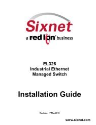
Architecture of the installationThe presence of the equipment in the following diagram is for information only,and does not represent the equipment of your installation.PERFORMANCEVITESSURF1.20 NdPROF 23.4 mEscEntDepth lock interface90-60-450TOPLINE bus20-61-001GND shieldData black12VDC whiteConnecting box90-60-121Figure 1loch Depthspeedometer- 4 - 33-60-024-000_UTI_GB_Performance DL18
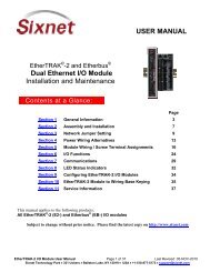
6000 <strong>Series</strong> - <strong>User's</strong> <strong>Guide</strong>Downloading the latest firmware....................................................................................................................... 51Performing the abt firmware upgrade ................................................................................................................ 52Appendix E : Sending AT Commands................................................................................................... 53Sending AT commands over an IP connection .................................................................................................. 53Sending AT commands over a serial connection............................................................................................... 53Appendix F : Dial-Up Networking in Windows.................................................................................... 55Installing the modem driver............................................................................................................................... 55Creating a Dial-Up Networking session ............................................................................................................ 55Appendix G : Warranty......................................................................................................................... 57Appendix H : Customer Support........................................................................................................... 581.6 Copyright © 2008 <strong>Sixnet</strong>, LLC BlueTree <strong>Modems</strong> 5
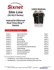
6000 <strong>Series</strong> - <strong>User's</strong> <strong>Guide</strong>Section 1 : Product OverviewIntroductionThe BlueTree <strong>6600</strong> series modems are rugged cellular modems built toprovide simple and reliable communication over a <strong>CDMA</strong> cellular datanetwork. They are typically used in applications such as Telemetry, SCADA,and WAN backup / Business Continuity.The models covered by this document are:• BT-<strong>6600</strong>• BT-6601• BT-6601EB• BT-6621The modem supports two operational modes: router mode, and IP passthroughmode.Router modeIn Router mode, which is the default mode, the modem manages local andwireless connections independently, and routes data packets back and forthbetween the two.Figure 1 - Router modeThe modem manages two connections at the same time, thus acting as agateway/router:• Cellular WAN connection: this is the Wide Area Network connection to thecellular network/Internet. The modem can be configured toautomatically and autonomously establish a packet data connection tothe cellular carrier and acquire a WAN IP address.1.6 Copyright © 2008 <strong>Sixnet</strong>, LLC BlueTree <strong>Modems</strong> 6
6000 <strong>Series</strong> - <strong>User's</strong> <strong>Guide</strong>• LAN connection: this is the local connection between the modem andany device attached to its serial/Ethernet/USB ports. In the case ofEthernet and USB, the modem acts as a DHCP server and assigns aprivate LAN IP address to the attached device. Alternatively, it canperform IP pass-through and assign the WAN IP to the attached host,thus becoming a fully transparent actor in the communication process.The modem then routes packets back and forth between its WAN and LANconnections, thus allowing the locally attached device to communicate withremote computers.IP pass-through modeIn IP pass-through mode, the modem assigns its WAN IP address directly tothe attached host. The modem remains reachable through its reserved TCPand UDP ports so remote administration and configuration is still possible.Note that this mode is not supported with the BT-6621.Figure 2 - IP pass-through mode1.6 Copyright © 2008 <strong>Sixnet</strong>, LLC BlueTree <strong>Modems</strong> 7
6000 <strong>Series</strong> - <strong>User's</strong> <strong>Guide</strong>Modem featuresTable 1 – Modem features3 different dataconnection interfacesEthernet switchPower-over-EthernetAutonomous & persistentconnection managementDHCP serverIP pass-throughIn-call diagnosticSerial IPRemote configurationRemote firmware upgradePassword protectionSerial/RS-232/COM, Ethernet, and USBAvailable on the BT-6621 only. The BT-6621 has anembedded 5-port Ethernet switch.The BT-6601EB model is a power sourcing equipmentwhich can be powered through the Ethernet port.Fully integrated TCP/IP protocols allow the modem toconnect autonomously to the packet network (Internet).This feature enables capabilities such as: in-call diagnostic,Serial-IP, stand-alone GPS, remote configuration andremote firmware upgrade.The modem’s DHCP server allows easy administration andsetup of the local network by automating IP addressassignmentThe modem can assign its WAN IP address to the attachedhost, thus disabling the DHCP server’s Network AddressTranslation. Even when performing pass-through, themodem remains reachable for remote administrationthrough its reserved TCP ports.The user can get modem status information while in a datacall, without interrupting the data sessionThe modem can provide a reliable mean of communicationwith serial-only legacy devices. It can encapsulates datacoming from the serial port into a TCP or UDP packet andsend it to a remote server on the packet network orInternet. It can decapsulate IP packets coming from thenetwork and send raw data to the serial port.The modem can be remotely configured or diagnosedusing BlueVue Device Manager or a terminal sessionThe modem’s firmware can be remotely upgraded usingBlueVue Device ManagerThe modem can be protected from tampering byrequesting the user to enter a password before theexisting modem configuration can be viewed or modified1.6 Copyright © 2008 <strong>Sixnet</strong>, LLC BlueTree <strong>Modems</strong> 8
6000 <strong>Series</strong> - <strong>User's</strong> <strong>Guide</strong>SpecificationsGeneral specificationsTable 2 – General specificationsWireless interfacePeak data ratesSerial interfaceDual-band <strong>CDMA</strong>2000 EVDO Rev. A (with diversity)Backward compatible with 1xRTT and IS95Download: 3.1 MbpsUpload: 1.8 Mbps1x RS-232 Serial DB9 115200bpsUSB interface1x USB2.0 miniLED indicatorsDimensionsPower InputPowerconsumptionEnvironmentalCertificationPower, WAN, Signal, RS232, Ethernet Link & ActivityBT-<strong>6600</strong>: 120 x 96 x 32 mm (4.7" x 3.77" x 1.25"), 453g (1.0 lb)BT-6621: 120 x 96 x 51 mm (4.7" x 3.77" x 2.00"), 500g (1.1 lb)8 - 30 Vdc (12Vdc nominal), Power over Ethernet on EB-6601Transmit: 155 mA average (Max. 443 mA)Standby: 55 mAOperating Temp: -40 to +75°C (-40 to 167°F)Shock: IEC68-2-27, Vibration: IEC68-2-6Humidity: 5 to 95% non-condensingHazardous Locations - Class I, Div. 2, Groups A,B,C,D, UL1604Electrical Safety - UL508/CSA22.2/14 (CUL)EMC- FCC, part 15 and Industry Canada, ICES-0031.6 Copyright © 2008 <strong>Sixnet</strong>, LLC BlueTree <strong>Modems</strong> 9
6000 <strong>Series</strong> - <strong>User's</strong> <strong>Guide</strong>Mechanical specifications1.6 Copyright © 2008 <strong>Sixnet</strong>, LLC BlueTree <strong>Modems</strong> 10
6000 <strong>Series</strong> - <strong>User's</strong> <strong>Guide</strong>Power specifications and consumptionPower is supplied to the modem via:• 4-pin Molex connector for the BT-<strong>6600</strong> model• 4-pin screw terminal for the BT-6601, BT-6601EB and BT-6621 models• DC 2.5mm round plug for all modelsPower is supplied to the modem via the 4-pin connector on the rear panel.The pins are described as follows:Table 3 – Power connector’s pinsO3GNDIGNPOSPin Name Description1 GND Ground2 POS Power supply input (8 to 30 VDC)Figure 3 – Powerconnector (Lookingat back of modem)3 IGN Ignition sense input (switches modem on or off)4 O3 Digital Output 3Power input to the modem is protected against reverse polarity and overvoltage.1.6 Copyright © 2008 <strong>Sixnet</strong>, LLC BlueTree <strong>Modems</strong> 11
6000 <strong>Series</strong> - <strong>User's</strong> <strong>Guide</strong>The modem’s power consumption is as follows:Table 4SituationBT-<strong>6600</strong>, BT-6601,BT-6601EBDraw in mABT-6621Idle with Ethernet active 113 mA 249 mAIdle with Serial DCE232activeTransmitting with EthernetactiveTransmitting with SerialDCE232 activeMaximum with all interfacesactive and transmit power isat the highest104 mA 133 mA198 mA 291 mA188 mA 175 mA311 mA 449 mAWiring instructions are provided in the Hardware Installation section.1.6 Copyright © 2008 <strong>Sixnet</strong>, LLC BlueTree <strong>Modems</strong> 12
6000 <strong>Series</strong> - <strong>User's</strong> <strong>Guide</strong>Modem viewsFigure 4 – BT-<strong>6600</strong>Figure 5 – BT-6601Figure 6 – BT6601EBFigure 7 – BT-66211.6 Copyright © 2008 <strong>Sixnet</strong>, LLC BlueTree <strong>Modems</strong> 13
6000 <strong>Series</strong> - <strong>User's</strong> <strong>Guide</strong>Indicators Lights (LED)Table 5 – LEDsLED Status Corresponding StatePowerSignalWANRS232OFFONFLASHOFFONFLASHOFFONFLASHOFFONFLASHModem is powered offModem is powered onFirmware errorNo cellular signal available (no service)Excellent signal strengthThe LED will flash faster as signal strength is betterCellular connection is not establishedCellular connection is established but no network data activityCellular connection is established but with network dataactivitySerial connection is not establishedSerial connection is established but no data activity with hostSerial connection is established but with data activity withhost1.6 Copyright © 2008 <strong>Sixnet</strong>, LLC BlueTree <strong>Modems</strong> 14
6000 <strong>Series</strong> - <strong>User's</strong> <strong>Guide</strong>Data Interface Specifications: Serial, Ethernet & USBEthernet PortThe modem's 10/100Mbps Ethernet port is compliant with the EIA-568standard, and requires a crossover RJ45 cable to connect to host terminals.The BT-6621 features a 5-port Ethernet switch allowing connectivity tomultiple local devices.USB Device PortThis is a USB2.0 Device interface on a Type B connector. It offers Ethernetover-USBfunctionality using the RNDIS driver.The BlueTree RNDIS driver must be installed before the USB interface can beused. You can obtain the driver at www.bluetreewireless.com.Serial Port (DB9)The modem’s serial port is an RS232 DCE, compliant with EIA-232 standard.The connector used is DB9 female and is shown in the illustration below.Figure 8 – Serial connector (looking at back of modem)For further serial wiring information, refer to the Hardware Installationsection.1.6 Copyright © 2008 <strong>Sixnet</strong>, LLC BlueTree <strong>Modems</strong> 15
6000 <strong>Series</strong> - <strong>User's</strong> <strong>Guide</strong>RESET button functionsTable 6 – Reset button functionsMode Pattern DescriptionHard reset Press for less than 3 seconds Standard rebootFactory restoreFW upgradeUSB pass-throughPress between 3 secondsand 10 secondsREG light flashes quicklyuntil button is releasedPress between 10 secondsand 15 secondsWAN light flashes quicklyPress for longer than 15secondsRS232 light flashes quicklyOverwrites user configuration withthe default factory settingsPuts the modem in advancedfirmware upgrade mode by restartingthe modem and running thebootloader only. Do not use unlessinstructed to by BlueTree Support.Puts the modem in main passthroughmode to the RF module,allowing CCT provisioning and PSTsupport. Do not use unless instructedto by BlueTree Support.1.6 Copyright © 2008 <strong>Sixnet</strong>, LLC BlueTree <strong>Modems</strong> 16
6000 <strong>Series</strong> - <strong>User's</strong> <strong>Guide</strong>Section 2 : BlueVue Device ManagerThe <strong>6600</strong> series modems can be configured using BlueVue Device Manager, asoftware application which is available as a free download at www.sixnet.com.Later sections of this guide will refer to configuration options in this program.For more in-depth information on using BlueVue Device Manager, refer to theBlueVue Device Manager <strong>User's</strong> <strong>Guide</strong>. It can be accessed from withinBlueVue itself by clicking the Help button, or downloaded separately atwww.sixnet.com.BlueVue Device Manager is a Graphical User Interface for modemconfiguration and administration that allows the user to:• Activate the modem (program account information) for use on thecellular network• Register the modem on the cellular network (WAN Setup)• Configure operation parameters (such as LAN setup or GPS)• Monitor diagnostic and status information• Perform firmware upgrades on the modem1.6 Copyright © 2008 <strong>Sixnet</strong>, LLC BlueTree <strong>Modems</strong> 17
6000 <strong>Series</strong> - <strong>User's</strong> <strong>Guide</strong>Connecting to the modemShould you run into any issues connecting to the modem, refer to theBlueVue Device Manager Troubleshooting appendix.Click on Tools > Settings > Connection tab to select the interface that willconnect your PC to the modem.Figure 9 – The different ways to connect to a modemUsing a serial cable:1) Select Serial2) Select the COM port in the dropdown list, then click OKUsing an Ethernet or USB cable:1) Select Modem IP2) Enter the appropriate modem IP then click OK. By default, theDHCP-assigned IPs will be 192.168.0.1 for Ethernet and192.168.111.1 for USB. If using USB, the driver must be installed asexplained in the Data Interface Specifications section.1.6 Copyright © 2008 <strong>Sixnet</strong>, LLC BlueTree <strong>Modems</strong> 18
6000 <strong>Series</strong> - <strong>User's</strong> <strong>Guide</strong>Connecting to a remote modem:1) Select Remote Configuration and click OK. A new panel will open tothe left of BlueVue Device Manager.2) Right-click Available <strong>Modems</strong> in the panel3) Click Add…4) Enter the modem’s information, then click OK. The description isoptional.5) The modem will be added to the list of Available <strong>Modems</strong>, which will besaved for easy access in the future. Double-click the modem namein order to connect to it.Figure 10 – Connecting to a remote modem1.6 Copyright © 2008 <strong>Sixnet</strong>, LLC BlueTree <strong>Modems</strong> 19
6000 <strong>Series</strong> - <strong>User's</strong> <strong>Guide</strong>Software overviewModem DiagnosticThis screen displays various technical information pertaining to themodem's state.Modem ConfigurationThis screen allows the user to configure the modem to suit theapplication requirements.Modem ActivationThis screen is where the user performs cellular account activation sothat the modem may connect to the cellular network.Modem WAN SettingsThis screen allows the user to set the connection profile on themodem, such as the user name and password of the account.HelpThis button opens the BlueVue Device Manager <strong>User's</strong> <strong>Guide</strong>, adocument that explains every parameter of BlueVue Device Managerin detail.1.6 Copyright © 2008 <strong>Sixnet</strong>, LLC BlueTree <strong>Modems</strong> 20
6000 <strong>Series</strong> - <strong>User's</strong> <strong>Guide</strong>Section 3 : Activation & WAN SetupActivationA modem must be activated and configured before it can be used on thecellular network. The steps below outline how to activate a modem. Toconfigure the modem to connect to the wireless network after activation hasbeen performed, skip to the next section.Obtaining a cellular account for the modemContact a cellular service provider or cellular dealer and request a <strong>CDMA</strong>account with the packet data service option for 1xRTT, 1xEV-DO, or1xEV-DO Rev. A. The provider will require the Electronic Serial Number (ESN)of the modem. The ESN is located on the label under the modem as well ason the modem’s packaging box.The cellular service provider will then provide the information required toactivate the modem.IMPORTANTAsk your cellular service provider whether the carrier blocks incomingconnections. If they do, you will be unable to communicate with the modemremotely unless you ask the service provider to allow incoming connections toyour application’s TCP and UDP ports. If possible, ask them to open thefollowing ports as well: TCP 20 and TCP 21 (used for firmware upgrades), TCP5070 (used by BlueVue Device Manager), and TCP 6070 (used fortroubleshooting and AT command configuration).Programming the account information into the modemThe steps required to program the account information into the modem areunique to each carrier. The Quick Start <strong>Guide</strong> booklet included in themodem package contains a step-by-step walkthrough for activating themodem. The latest version of the Quick Start <strong>Guide</strong> is also available fordownload at www.bluetreewireless.com.1.6 Copyright © 2008 <strong>Sixnet</strong>, LLC BlueTree <strong>Modems</strong> 21
6000 <strong>Series</strong> - <strong>User's</strong> <strong>Guide</strong>Confirming the success of activationOnce the activation process above is complete, navigate to WAN (WANSettings). The modem’s phone number should be displayed at the top left asshown in Figure 11.Figure 11 – Confirming the success of activation1.6 Copyright © 2008 <strong>Sixnet</strong>, LLC BlueTree <strong>Modems</strong> 22
6000 <strong>Series</strong> - <strong>User's</strong> <strong>Guide</strong>WAN SetupAfter the modem has been activated, it must be configured in order toauthenticate for use with the cellular network.Enter the account informationNavigate to WAN (WAN Settings) to configure the WAN connection oncethe modem has been activated.Figure 12 – Editing the account information1) Enter #777 as the Dial String2) Enter the User Name and Password if provided by your cellular carrier3) Select Always On or On Demand (explained below) depending on thedesired connection initiation behavior.1.6 Copyright © 2008 <strong>Sixnet</strong>, LLC BlueTree <strong>Modems</strong> 23
6000 <strong>Series</strong> - <strong>User's</strong> <strong>Guide</strong>When the modem is set to Always On, it will attempt to maintain a permanentconnection to the cellular network on its own. Most applications will requirethe modem to be remotely accessible at any time, and will require themodem to be set to Always On.When the modem is set to On Demand, the modem does not connect to thecellular network unless told to by the attached terminal. If disconnected fromthe cellular network, it will not attempt to reconnect. The most common OnDemand scenario is when using the serial port in order to establish a PPPsession through a Dial-Up Networking (DUN) connection.Unless you are sure the modem should be set to On Demand, the modemshould be set to Always On.Testing the connectionOnce you've finished entering the settings, and once a connection isestablished (depending on the connection initiation behavior describedabove), navigate to DIAG (Modem Diagnostic): the modem’s WAN IPshould be displayed as outlined in Figure 13. This is the IP address that hasbeen assigned to the modem by the cellular carrier. At this time, the modem’sLNK light will stay on as long as the connection is maintained.Figure 13 – Testing the connection1.6 Copyright © 2008 <strong>Sixnet</strong>, LLC BlueTree <strong>Modems</strong> 24
6000 <strong>Series</strong> - <strong>User's</strong> <strong>Guide</strong>Section 4 : LAN SetupEthernet and USB LANComputers and devices that use the modem’s Ethernet and USB connectivityexperience much higher transfer speeds and they employ all the benefits ofTCP/IP communication.LAN configurationWhether an Ethernet or USB cable is used, it is essential that both the modemand the attached device be within the same LAN subnet for IP communicationto take place. By default, the modem has a DHCP server running, which willinitially assign the following IP address to the attached device (providing thedevice is set to use DHCP):Table 7 – DHCP IP assignmentModem IPHost IPEthernet 192.168.0.1 192.168.0.4USB 192.168.111.1 192.168.111.201.6 Copyright © 2008 <strong>Sixnet</strong>, LLC BlueTree <strong>Modems</strong> 25
6000 <strong>Series</strong> - <strong>User's</strong> <strong>Guide</strong>Figure 14 – Default LAN IP configurationIf the attached device must use a specific (static) IP, then the modem's LANconfiguration must be changed so that the modem's IP lies in the samesubnet as the device. Navigate to CONF (Modem Configuration) > LAN IPand change the parameters under Ethernet or USB.Figure 15 – Sample modem configuration for communicatingwith a device that has the IP 10.127.0.17DHCP serverAs mentioned above, the modem has a DHCP server which automaticallyassigns an IP to the attached device. If an Ethernet hub or switch isconnected to the modem’s Ethernet port, the modem will assign an IPaddress to each device connected to the hub or switch, for a maximum of 254devices, provided the devices are configured as DHCP clients (“Dynamic” or“Automatic” IP configuration). The DHCP server can be configured or turnedoff at CONF (Modem Configuration) > LAN IP as shown above.1.6 Copyright © 2008 <strong>Sixnet</strong>, LLC BlueTree <strong>Modems</strong> 26
6000 <strong>Series</strong> - <strong>User's</strong> <strong>Guide</strong>Dial-up Networking (DUN) over serialNote:Regardless of the modem type, using a serial cable will cap the bandwidth at115200 kbps. For owners of EV-DO modems (4600/A & 5600/A), the serialport will be a bottleneck in terms of performance, as it will reduce the datathroughput to approximately 5% of its maximum potential, and even less forEV-DO Rev. A modems. Whenever possible, use an Ethernet or USBconnection to take full advantage of throughput.Some terminals do not have RJ45 Ethernet or USB connectors and requireusing a DB9 RS232 standard serial connector to interface with the modem.• If the attached device is not programmable (smart), then you cannotdo DUN, and will have to use the Serial IP feature to communicatewith the device. Refer to the Serial IP section for details.• If the modem will be used with a programmable device that can makePPP connections, then refer to that device's documentation to createthe dial-up session. The phone number to dial will be #777. Theusername and password, if any, will be those provided by your cellularservice provider.• If the modem will be used with a PC that must make a PPP connection,then the user must install a standard modem driver on the COM portto which the modem is physically connected, and then create a dial-upconnection running on that driver. This dial-up connection will dial themodem so that a PPP session is established between modem and PC.Meanwhile, the modem will make a PPP session of its own to connectto the network. For a walkthrough on creating a DUN connection inWindows, refer to the Dial-Up Networking in Windows appendix.1.6 Copyright © 2008 <strong>Sixnet</strong>, LLC BlueTree <strong>Modems</strong> 27
6000 <strong>Series</strong> - <strong>User's</strong> <strong>Guide</strong>Section 5 : IP Networking FeaturesAs mentioned previously, the modem acquires an external public or private IPaddress (WAN IP, or Wide Area Network IP) from the cellular network uponestablishing a connection. A remote user can communicate with the modemor a host behind the modem, however the appropriate port-forwarding, DMZor IP pass-through and LAN IP configuration must be set on the modem. Readon for a description of each configuration option.Some carriers disable remote access as a security measure. If you are certainthat the modem is on the cellular network (i.e., it has acquired a WAN IP) andthat the local network is set up properly, but you cannot reach the modemremotely, confirm with the carrier that incoming IP data traffic is allowed onthe required TCP or UDP port. Read the BlueVue Device ManagerTroubleshooting section for more details.Port-forwardingSince the 6000 series modem is a network address translation (NAT) enabledrouter, the remote computer connecting to the modem’s cellular WAN IPcannot access devices/servers on the modem’s LAN if the modem is notspecifically configured to forward the appropriate ports to the LANdevices/servers. Port-forwarding, or tunneling, is the act of relaying anincoming packet to one or more local destinations depending on the port(s)through which the packet came.The main use of port-forwarding is to allow an external user to reach a porton a private IP address from the outside via a NAT. This allows remotecomputers to connect to a specific computer within a private LAN, dependingon the port used to connect.To set up the modem's port forwarding rules, navigate to CONF (ModemConfiguration) > Port Forwarding/DMZ.1.6 Copyright © 2008 <strong>Sixnet</strong>, LLC BlueTree <strong>Modems</strong> 28
6000 <strong>Series</strong> - <strong>User's</strong> <strong>Guide</strong>Figure 16 – Port-forwarding entriesThe WAN Port is the destination port number used by the remote computerand the LAN Port is where the data is forwarded to. Typically the WAN portand LAN port are the same, however any port can be used on the WAN side,as long as it points towards the correct LAN port. Select the appropriateprotocol (TCP or UDP), and submit the new settings.DMZThis feature, when enabled, instructs the modem to port-forward all incomingtraffic to a single IP destination on the LAN. An exception will be made fortraffic coming on the ports designated by the port-forwarding rules (thiswould be ports 9000, 23, and 777 in Figure 13). This exception can beoverridden by checking the “DMZ overrides all forwarded ports below”checkbox.1.6 Copyright © 2008 <strong>Sixnet</strong>, LLC BlueTree <strong>Modems</strong> 29
6000 <strong>Series</strong> - <strong>User's</strong> <strong>Guide</strong>Figure 17 – Enabling DMZDMZ is ideal in situations where there is already a server on the LAN thathandles port-forwarding, as it avoids having to re-program all the portforwardingrules into the modem. It is also practical when the user does notknow which ports his local device listens on, and just wants everything towork with minimal configuration.DMZ can be enabled at CONF (Modem Configuration) > PortForwarding/DMZ.IP pass-throughNoteIP pass-through does not work in conjunction with port-forwarding and DMZ.When it is enabled, both port-forwarding and DMZ will stop functioning.The BT-6621 does not support IP pass-through.When this feature is enabled, the modem will disable NAT and assign its WANIP address to the attached host. This will solve VPN authentication issues thatare caused by NAT. The modem will remain reachable though its reservedTCP and UDP ports.To enable IP pass-through, navigate to CONF (Modem Configuration) >LAN IP and select the data interface to perform pass-through on, then checkthe “Enable IP Pass-through” checkbox.Figure 18 – Enabling IP passthroughIf the host is attached to the modem via an Ethernet cable, then the hostmust have DHCP enabled (i.e., it should be perform automatic IP negotiationinstead of using a pre-defined static IP). If the host is attached to the modemvia a serial cable, IP pass-through will only activate when the host creates aPPP session to the modem.1.6 Copyright © 2008 <strong>Sixnet</strong>, LLC BlueTree <strong>Modems</strong> 30
6000 <strong>Series</strong> - <strong>User's</strong> <strong>Guide</strong>Dynamic IP registrationThis feature allows the modem to report a message to a user-configurable IPaddress every time its WAN IP address changes.It is useful when the cellular account is associated with a dynamic IP address.Since the WAN IP address will be changing regularly, it will be impossible forthe user to know which WAN IP address is assigned to the modem. WithDynamic IP Registration enabled, the modem will notify a remote server ofthe new WAN IP address as well as the modem’s ESN in hexadecimal format.The IP Registration packet can be sent using either TCP or UDP.To configure Dynamic IP Registration, navigate to CONF (ModemConfiguration) > General, and set the destination IP address and port. Theregistration timer is a value (in minutes) that controls how often the modemshould report its IP to the server. If it is set to zero, the modem will report itsWAN IP address upon boot-up or upon acquiring a new IP address from thecellular carrier after losing the cellular connection. If it is set to a valuebetween 1 and 65535, then it will report its ESN and WAN IP regularly at thespecified interval.Figure 19 – Enabling Dynamic IP Registration1.6 Copyright © 2008 <strong>Sixnet</strong>, LLC BlueTree <strong>Modems</strong> 31
6000 <strong>Series</strong> - <strong>User's</strong> <strong>Guide</strong>Password protectionThis feature allows administrators to restrict unauthorized users fromconfiguring the modem by requiring a password whenever the modem’sconfiguration ports are accessed.Figure 20 – Enabling password protectionTo enable password protection:1) Navigate to CONF (Modem Configuration) > Password and checkthe “Enable” box.2) Select the interfaces to prompt for a password on. The WANinterface (remote connections) is the most commonly passwordprotectedinterface, however some users may wish to passwordprotectboth the WAN & LAN interfaces. Note that the modem cannotprevent configuration changes made from its serial port.3) Finally, set the modem password. The password must be a casesensitivestring that is 6-30 characters long.4) Click Submit to save the changes.1.6 Copyright © 2008 <strong>Sixnet</strong>, LLC BlueTree <strong>Modems</strong> 32
6000 <strong>Series</strong> - <strong>User's</strong> <strong>Guide</strong>Section 6 : Serial IPThis feature allows communication over the cellular network in two commonsetups. The first is a server communicating with a remote serial-only deviceand the other, a serial-only device communicating with another remote serialonlydevice. Serial IP is used to emulate a direct serial connection to theattached device, or to emulate a landline modem. The modem becomes atransparent middleman routing data back and forth between the poller andthe pollee. Serial IP is most commonly used in telemetry applications such asmeter reading and SCADA devices.Figure 21 – Serial IPWhen the modem is in Serial IP mode, IP packets intended for the attachedserial device have their IP headers stripped before being passed on to thedevice. This means that the serial device receives raw serial data that it canunderstand. Inversely, when the serial device is sending data, the modemencapsulates this data in IP packets to be transmitted over-the-air to theremote destination.When a Serial IP server is running, the modem waits until a connection ismade on the defined Serial IP port, then triggers Serial IP mode. Theincoming data will be relayed to the attached serial device. Any output fromthe serial device will be sent to the IP of the remote computer that made theconnection on the port that the remote computer used to make theconnection.1.6 Copyright © 2008 <strong>Sixnet</strong>, LLC BlueTree <strong>Modems</strong> 33
6000 <strong>Series</strong> - <strong>User's</strong> <strong>Guide</strong>When using Serial IP, the modem configuration depends on the applicationrequirements. The four different scenarios are documented in a Support Note(#SN0703121) available at:http://www.bluetreewireless.com/support/downloads/documents/details.asp?id=691.6 Copyright © 2008 <strong>Sixnet</strong>, LLC BlueTree <strong>Modems</strong> 34
6000 <strong>Series</strong> - <strong>User's</strong> <strong>Guide</strong>Section 7 : Hardware InstallationMounting the modemThe modem can be mounted in 3 different ways:• Horizontally using two #6 screws pan or fillister head onto itshorizontal mounting feet• Vertically using two #6 screws pan or fillister head onto its verticalmounting feet• Vertically using a DIN rail clip1.6 Copyright © 2008 <strong>Sixnet</strong>, LLC BlueTree <strong>Modems</strong> 35
6000 <strong>Series</strong> - <strong>User's</strong> <strong>Guide</strong>Cellular antennaThe selected cellular antenna(s) must meet the following specifications:• Maximum rated gain of 3dBi for Cellular band and 4dBi for PCS band• Dual-band 800 & 1900 MHz• Nominal 50 ohm impedance• Voltage Standing Wave Ratio (VSWR) less then 2.5:1• Male SMA connectorThe length of the antenna cable may affect the signal strength. Choose theappropriate cable type and length. The table below provides can help predeterminethe loss to expect.Table 8 – dB loss per 100 feet of cable typeCable typeLoss per 100 feet8216 (RG58) 31 dB8267 (RG213) 7.6 dBLMR-400LMR-500LMR-600LMR-12003.9 dB3.15 dB2.5 dB1.26 dBInstallation and verificationWhen installing the antenna, follow the FCC and Industry Canada guidelinesand keep the following in mind:• Mount the antenna(s) at least 30 cm (12 inches) from other antennas• Do not install the antenna in a closed metallic enclosure (such as acabinet or the trunk of a car).Once a modem has a signal, the REG LED indicator will start flashing,indicating that the modem is registered on the cellular network (i.e. withincoverage). Additionally, BlueVue Device Manager will display the receivedsignal strength (RSSI) in the top right. The modem should have at the veryleast one bar of signal strength.1.6 Copyright © 2008 <strong>Sixnet</strong>, LLC BlueTree <strong>Modems</strong> 36
6000 <strong>Series</strong> - <strong>User's</strong> <strong>Guide</strong>Antenna diversityThe 4600/A & 5600/A modems have two antenna connectors available,labeled RF-1 and RF-2.• RF-1 : This is the main antenna that is used for data transmission. It ismandatory to have RF-1 connected to an antenna.• RF-2 : This is the diversity antenna, used to improve on the signalstrength obtained from RF-1. This antenna is not mandatory howeverit will improve throughput.Diversity is a transmission technique that consists of using two separateantennas to achieve the most robust cellular signal possible. Diversity willhelp achieve fast, reliable data throughput in applications that require a highamount of bandwidth.The diversity antenna should be placed at least 13.8 inches away from themain antenna. 18 inches is an ideal, safe distance as it also covers theantennas’ diameters.1.6 Copyright © 2008 <strong>Sixnet</strong>, LLC BlueTree <strong>Modems</strong> 37
6000 <strong>Series</strong> - <strong>User's</strong> <strong>Guide</strong>Ethernet cableIf you are connecting to the modem via the Ethernet port, you will need acrossover category 5 cable with two 8-pin RJ45 connectors on each end.To visually confirm that Ethernet cabling was done properly, check the LEDindication on the Ethernet port located at the rear panel of the modem. TheLink LED should be on when the right cable is used.USB cableThis is an Ethernet-over-USB connection which behaves like an Ethernetconnection. If you are connecting to the modem via the USB port, you willneed a TypeA/TypeB male USB cable. In order for the USB connection towork, you need to install the BlueTree USB driver which is available atwww.bluetreewireless.com.Serial cableThe modem has all its serial port pins enabled. If all the pins are enabled onthe attached serial device, it is important to know whether the device is usingDTE or DCE as a communication mode.The modem is a DCE device, so use a straight-through serial cable betweenthe modem and a DTE device such as a terminal. Use a NULL modem cableadapter between the modem and a DCE device such as another modem.If using custom wiring or if some pins are disabled, follow the guidelinesbelow. The wiring will vary depending on whether the attached serial device isa DTE or DCE.1.6 Copyright © 2008 <strong>Sixnet</strong>, LLC BlueTree <strong>Modems</strong> 38
6000 <strong>Series</strong> - <strong>User's</strong> <strong>Guide</strong>Power sourceIMPORTANTAny installations involving electrical wiring and connections should be done bysomeone who is experienced in this field.As described in the Power specifications and consumption section, the modemcan be powered using:• 4-pin Molex connector for the BT-<strong>6600</strong> model• 4-pin screw terminal for the BT-6601, BT-6601EB and BT-6621 models• DC 2.5mm round plug for all modelsPowering up the modemThe modem will power up as soon as an 8 to 30 Vdc voltage is applied to itsPOS input; and shuts off when this input voltage is below 4 Vdc.Testing the power connectionCheck the PWR light on the modem: if it is turned on then the modem ispowered. If it’s off, then review the installation procedures.If LED indicators are not accessible to the installer a personal computer canbe used to verify its functionality by running BlueVue Device Manager andattempt to connect to the modem.1.6 Copyright © 2008 <strong>Sixnet</strong>, LLC BlueTree <strong>Modems</strong> 39
6000 <strong>Series</strong> - <strong>User's</strong> <strong>Guide</strong>Appendix A : BlueVue Device ManagerTroubleshootingBefore troubleshooting, download and install the latest version of BlueVueDevice Manager from www.sixnet.com .(ETHERNET) The BlueVue Device Manager message boxdisplays “Detecting Modem at 192.168.0.1” indefinitelyConnect the modem to a computer using a cross-over Ethernet cable, andopen BlueVue Device Manager. Set BlueVue Device Manager’s connectiontype to IP. BlueVue Device Manager will attempt to connect to 192.168.0.1 bydefault.Possible cause #1The wrong type of cable is being used.TroubleshootingCheck the Link LED on the modem’s Ethernet connector (located on the backof the modem). If the LED is off, check the cable type. A cross-over RJ-45Ethernet cable is required for communication between the modem and thePC. A standard Ethernet cable won’t do.Possible cause #2The computer’s local IP configuration is incorrect.Troubleshooting1) In Windows XP, go to Control Panel > Network Connections andselect the local area connection that corresponds to the Ethernetport in the “LAN or High-Speed Internet” list (it’s usually “Local AreaConnection 1”).2) Right-click the connection and click Properties. Select InternetProtocol (TCP/IP) in the list and click Properties.3) Write down the existing values in order to restore them afterconfiguring the modem, then select Obtain an IP addressautomatically and Obtain DNS server address automatically. Thecomputer will now be ready to use the modem to access the Internet.1.6 Copyright © 2008 <strong>Sixnet</strong>, LLC BlueTree <strong>Modems</strong> 40
6000 <strong>Series</strong> - <strong>User's</strong> <strong>Guide</strong>Possible cause #3The modem is in a different network and DHCP is disabled. (This issue doesnot apply to brand-new modems at factory settings. It only applies tomodems that have had their configuration modified.)TroubleshootingFollow the instructions below:1) Connect the computer to the modem using a straight serial cable2) Set BlueVue Device Manager to connect to the modem over theserial port by changing the connection type to Serial3) Once the modem has been accessed, navigate to CONF (ModemConfiguration) > LAN IP4) Under Ethernet, set the Modem IP to 192.168.0.15) Confirm that DHCP is enabled and that the DHCP Start IP is192.168.0.4. Set the End IP range to any value higher than192.168.0.4. The default is 192.168.0.39.6) Click Submit to save the changes7) Reset the modem and restart the computer2. (USB) The BlueVue Device Manager message box displays“Detecting Modem at 192.168.111.1” indefinitelyPossible cause #1The USB driver is not installed.TroubleshootingThe USB driver for Windows must be installed before the modem’s USBfunctionality can be used. Visit www.sixnet.com to download the USB driverthen install it. It may be necessary to reboot the computer.Possible cause #2The modem has an old firmware version which does not support USB.TroubleshootingThe USB functionality was introduced in version 3.0 of the firmware.Upgrade the modem’s firmware to the latest version available atwww.sixnet.com. A walkthrough can be found in the Firmware Upgradesappendix.1.6 Copyright © 2008 <strong>Sixnet</strong>, LLC BlueTree <strong>Modems</strong> 41
6000 <strong>Series</strong> - <strong>User's</strong> <strong>Guide</strong>3. (SERIAL) The BlueVue Device Manager message box displays“COMx is already in use”Possible causeAnother software application is already using the COM port.TroubleshootingClose all applications that could be using the serial port, including otherinstances of BlueVue Device Manager, then try again.4. (SERIAL) The BlueVue Device Manager message boxdisplays “Detecting modem on COMx” indefinitely, or displays awarning about an unsupported modemExamine the DTR LED. If it is off, then the computer and the modem are notcommunicating.Possible causeThe wrong type of cable is being used.TroubleshootingUse a straight-through RS232 standard DB9 cable. If using a custom-madecable, confirm that it follows the instructions in Section 11.6. If the correctcable is being used, then the DTR LED on the modem will turn on whenBlueVue Device Manager attempts to access it.Possible causeBlueVue Device Manager is trying to connect to the wrong COM port.TroubleshootingConfirm that the correct COM port is selected in BlueVue Device Manager. Itwill attempt to use COM1 by default, but computers with built-in dial-upmodems might have COM1 assigned to the built-in modem instead. To set theCOM port BlueVue Device Manager should use, click on Tools > Settings >Connection and browse through the available COM ports. If the DTR LEDturns on, then you will have found the right COM port.1.6 Copyright © 2008 <strong>Sixnet</strong>, LLC BlueTree <strong>Modems</strong> 42
6000 <strong>Series</strong> - <strong>User's</strong> <strong>Guide</strong>5. (SERIAL) The BlueVue Device Manager message box displays“Detecting modem on COMx” and then “Modem is notresponding”Possible causeBlueVue Device Manager and the modem are using different serial portsettings.TroubleshootingInstalling BlueVue Device Manager 1.7.1 or later will allow communicationwith a modem regardless of its serial settings.6. The BlueVue message box displays “[Modem]…is notresponding to expected commands. Contact BlueTree Support.”Possible causeBlueVue Device Manager has detected a potential hardware issue.TroubleshootingContact <strong>Sixnet</strong> support at support@sixnet.com.1.6 Copyright © 2008 <strong>Sixnet</strong>, LLC BlueTree <strong>Modems</strong> 43
6000 <strong>Series</strong> - <strong>User's</strong> <strong>Guide</strong>Appendix B : Activation TroubleshootingWhen the modem is connected to the cellular network, its LNK LED will stayon, and BlueVue Device Manager’s Modem Diagnostic screen will display aWAN IP. If the modem is not connected, the LNK light will be off, orintermittent, and the displayed WAN IP will be “N/A”. This appendix coversissues with connecting to the network. If your modem is connected to thenetwork but you cannot browse the internet, refer to Appendix X.Each of the following conditions must be met before a modem canconnect to the cellular network:1) The modem must be within coverage, and have an acceptable RFsignal strength2) The modem must be activated for use on the cellular network3) The modem must be configured to connect to the cellular network4) If the cellular carrier requires a user name and password, the modem’sconnection parameters (WAN Settings) must be configuredVerifying the signal strengthThe modem’s REG LED should always be flashing when it has a strongenough signal to detect a cellular network. Additionally, the signal strength isdisplayed in the information box in the top right of the BlueVue DeviceManager window. The minimum required for communication is 1 signalstrength bar; however, a signal this weak is not likely to provide a stableconnection.If the REG LED stays on, or if the signal strength is lower than -98 dBm(such as -105 dBm), there may be an issue with the antenna or the modemmay be in a low coverage area.Figure 22 – Modem with with good signal strengthConfirming the success of activationOnce a modem has been activated, BlueVue Device Manager will display itsphone number in the WAN (Modem WAN Settings) screen.If the phone number is blank, or does not correspond to the account’s phonenumber, then activation has not been performed. Follow the instructionswritten in the Quick Start <strong>Guide</strong> that shipped with the modem to performactivation. The latest Quick Start <strong>Guide</strong> is also available for download atwww.sixnet.com.1.6 Copyright © 2008 <strong>Sixnet</strong>, LLC BlueTree <strong>Modems</strong> 44
6000 <strong>Series</strong> - <strong>User's</strong> <strong>Guide</strong>Figure 23 – Phone number being displayed on the ModemDiagnostic screen after activationConfiguring the Connection InitiationThe modem must be configured to connect to the network.To do this, open BlueVue Device Manager and navigate to WAN (WANSettings), and then ensure that the following settings are applied:1) The Dial String is #7772) The Connection Initiation is Always OnClick Submit to apply any changes. The modem should now connect to thecellular network. Refer to this section’s introduction for instructions on how toverify whether your modem is connected to the network or not.Configuring the User ProfileIf the modem’s LNK LED turns on for a few seconds then turns off, thisindicates that authentication on the cellular network is failing. Themodem’s User Profile will need to be configured.Navigate to WAN (WAN Settings). Enter the user name and password asprovided by the cellular service provider.ConclusionAs mentioned previously, when the modem is connected to the cellularnetwork, BlueVue Device Manager’s Modem Diagnostic screen will display avalid WAN IP and the LNK LED will remain on.1.6 Copyright © 2008 <strong>Sixnet</strong>, LLC BlueTree <strong>Modems</strong> 45
6000 <strong>Series</strong> - <strong>User's</strong> <strong>Guide</strong>Figure 24 – WAN IP being displayed after the modemsuccessfully connects to the cellular networkIf after going through all of the above troubleshooting steps, the modem stilldoes not acquire a WAN IP, then it is very likely that the account is notenabled by the cellular carrier, or that there has been a mix-up on the carrierside with the account details. Contact the cellular service provider and askthem to confirm that the phone number assigned matches the modem’s ESN(electronic serial number) as shown in DIAG (Modem Diagnostic), and thatthe account is ready to be used.1.6 Copyright © 2008 <strong>Sixnet</strong>, LLC BlueTree <strong>Modems</strong> 46
6000 <strong>Series</strong> - <strong>User's</strong> <strong>Guide</strong>Appendix C : TroubleshootingThis appendix assumes that the modem is currently online, and therefore theproblem cannot be attributed to a lack of connectivity. BlueVue DeviceManager’s Modem Diagnostic screen should be displaying a valid WAN IP, i.e.an IP other than “N/A”. If this is not the case, refer to Appendix F: ActivationTroubleshooting.You cannot browse the InternetPossible cause #1 (Ethernet only)The computer’s local IP configuration is incorrect.TroubleshootingThe computer must be in the same subnet as the modem and must have themodem set as its gateway. The easiest way to achieve this is to enableautomatic IP configuration (DHCP) on the computer.1) In Windows XP, go to Control Panel > Network Connections andselect the local area connection that corresponds to theEthernet port in the “LAN or High-Speed Internet” list (it’s usually“Local Area Connection 1”).2) Right-click the connection and click Properties. Select InternetProtocol (TCP/IP) in the list and click Properties.3) Write down the existing values in order to restore them if needed,then select Obtain an IP address automatically and Obtain DNSserver address automatically. Click OK to close both dialog boxes,and reset the computer. It should now be ready to use the modem toaccess the Internet.Possible cause #2 (Serial only)You’re connected to the modem using a serial cable and did not start a Dial-Up Networking session.TroubleshootingUnlike Ethernet/USB, you must configure Windows to use a serial cable toaccess the network. Even though the modem is connected to the Internet,your computer is not configured to browse the Internet through the modem.You will need to install a standard 33600bps modem driver and create aDial-Up Networking session in order to be able to browse the internet.Refer to the Dial-Up Networking in Windows appendix for a walkthrough forcreating a Dial-Up Networking connection in Windows XP.1.6 Copyright © 2008 <strong>Sixnet</strong>, LLC BlueTree <strong>Modems</strong> 47
6000 <strong>Series</strong> - <strong>User's</strong> <strong>Guide</strong>Possible cause #3Your web browser is configured to use a proxy which cannot be accessed bythe modem.Troubleshooting1) Open a command prompt window by clicking Start > Run thenentering “cmd” in the Run window.2) At the command prompt, type ping google.com and press Enter.If you get a “Reply from xxx.xxx.xxx.xxx: bytes=32 time=xxxms TTL=xxx”response, then your web browser is configured to use a web proxy which ispreventing you from browsing the Internet through the modem. Consult yournetwork administrator for help on fixing this issue.Possible cause #4The cellular account does not allow web access.TroubleshootingCertain cellular accounts, particularly those where security is a high concern,do not allow web access. If you are attempting to test the connection bybrowsing the Internet, you may not be able to do so because of this accountrestriction.(TCP/IP) You cannot communicate with a computer/devicebehind the modemThis section is meant for TCP/IP connectivity. If the device is a serial-onlydevice, skip to the next issue.Possible cause #1Your cellular carrier is operating a firewall which is blocking your attempts toconnect.TroubleshootingCertain carriers have a firewall turned on by default that blocks all incomingconnections.1) Open a command prompt window by clicking Start > Run thentyping “command” in the Run window2) Type telnet xxx.xxx.xxx.xxx 6070 where x is the modem’s WAN IPas assigned by the carrier1.6 Copyright © 2008 <strong>Sixnet</strong>, LLC BlueTree <strong>Modems</strong> 48
6000 <strong>Series</strong> - <strong>User's</strong> <strong>Guide</strong>If you do not connect and see a “Welcome to BlueTree Wireless” message,then your carrier is likely blocking incoming connections. Contact your cellularservice provider and ask them to open the TCP and UDP ports you will beusing to access the device.Possible cause #2Your computer (from which you are initiating the connection) or network hasa firewall blocking outgoing connections.TroubleshootingConfirm with your IT technician that no firewall is blocking outgoingconnections.Possible cause #3You did not perform the appropriate port-forwarding rules on the modem.TroubleshootingThe modem must be configured to forward incoming traffic to the device,otherwise your connection attempts will never reach the device. Refer to IPNetworking Features for further details.(SERIAL) You cannot communicate with a device behind themodemFirst, make sure the modem is configured to enable outside communicationwith the attached device. Refer to the “Serial IP” section of the main guide fordetails. The troubleshooting steps below assumes the modem is configuredproperly.Possible cause #1The modem and the device are using different serial port settings.TroubleshootingUsing BlueVue Device Manager, navigate to CONF (Modem Configuration)> Serial Port, and change the serial port settings to the same values asthose of the serial device. If the CTS and RTS pins are partially (or both)disabled, set the modem to use no flow control (“none”).Possible cause #2The cable wiring is incorrect.1.6 Copyright © 2008 <strong>Sixnet</strong>, LLC BlueTree <strong>Modems</strong> 49
6000 <strong>Series</strong> - <strong>User's</strong> <strong>Guide</strong>TroubleshootingRefer to Section 11.6 for details on the required cable type.Possible cause #3The DTR signal is inconsistent.TroubleshootingA flickering DTR signal will interrupt communication with the modem. Themodem can be configured to ignore the changes in the DTR state. In BlueVueDevice Manager, navigate to CONF (Modem Configuration) > Serial Port,and check the option to Ignore DTR.1.6 Copyright © 2008 <strong>Sixnet</strong>, LLC BlueTree <strong>Modems</strong> 50
6000 <strong>Series</strong> - <strong>User's</strong> <strong>Guide</strong>Appendix D : Firmware UpgradesBlueTree periodically releases updates to the BlueX firmware used on the<strong>6600</strong> modems. These updates improve the modem's stability andfunctionality by addressing bugs and introducing new features. It isrecommended to always upgrade to the latest version of the firmware.Firmware upgrades can only be performed if BlueVue Device Manager isaccessing the modem through an IP connection such as a local Ethernet, USBconnection or a remote connection over the Internet. It is not possible toupdate the firmware using a serial cable.To upgrade a modem remotely over the air, it must have a static IP accountwith the cellular carrier. If the modem has a dynamic IP (i.e. if its IP changesregularly), and the IP is changed when the modem resets during the firmwareupdate procedure, then BlueVue Device Manager will not be able to reconnectand finalize the update, and the modem will revert back to its previousfirmware the next time it is reset.Downloading the latest firmwareDownload the latest standard firmware package files fromwww.bluetreewireless.com, and extract the zip file to a folder on your harddrive. It should contain a file named abt_version.upd and a file namedkbt_version.upd as well as a document containing the same upgradeinstructions as this appendix.1.6 Copyright © 2008 <strong>Sixnet</strong>, LLC BlueTree <strong>Modems</strong> 51
6000 <strong>Series</strong> - <strong>User's</strong> <strong>Guide</strong>Performing the abt firmware upgradeFigure 25 – Upgrading the firmware1) Navigate to CONF (Modem Configuration) > Firmware.2) Click the magnifying glass icon and locate the abt_version.upd filefrom the package that you extracted at the first step.3) Click Upgrade.4) Wait for BlueVue Device Manager to confirm that the firmware updatewas completed. If the upgrade is being performed locally, it shouldapproximately take 2 minutes. If it the upgrade is being performedremotely, then it could take up to 5 minutes depending on uploadspeed.1.6 Copyright © 2008 <strong>Sixnet</strong>, LLC BlueTree <strong>Modems</strong> 52
6000 <strong>Series</strong> - <strong>User's</strong> <strong>Guide</strong>Appendix E : Sending AT CommandsAT commands are short text strings that can be sent to the modem to set,remove and query a modem's configuration parameters. BlueVue DeviceManager is a software application that provides a graphical user interfacedesigned to avoid manual entry of AT commands. However, not allconfiguration commands are available in BlueVue. Additionally, BVDM is onlyavailable in Microsoft Windows operating systems. For these and variousother reasons, some users may want to send AT commands to the modem.The full list of AT commands and their description is in the 4000, 5000 & 6000<strong>Series</strong> AT Command Reference manual, available at www.sixnet.com.IMPORTANT:After sending AT commands to configure the modem, you must send AT&Wto save the changes. Otherwise, they will be lost the next time the modemresets. You do not need to send AT&W after each command: you can send itjust once after you’re done configuring the modem.Sending AT commands over an IP connectionIf you can reach the modem using a crossover Ethernet cable, or a USB cable,or remotely to the modem's WAN IP, AT commands can be sent byperforming a TCP (telnet) connection to the modem on port 6070. Here is aneasy way to do this in Windows:1) Click the Start button, then Run.2) In the Run window, type command and click OK. A command promptwindow will open.3) Type telnet xxx.xxx.xxx.xxx 6070 (replacing the x’s with themodem’s IP) and press Enter. By default, the modem's IP will be192.168.0.1 for Ethernet, and 192.168.111.1 for USB. If connecting toa remote modem, you will need to know its WAN IP.4) You should get a "Welcome to BlueTree Wireless" message. You cannow send AT commands.Sending AT commands over a serial connectionIf connected to the modem using a straight DB9 serial cable, AT commandscan be sent using a terminal emulation software. The terminal and themodem must be using identical serial port settings to communicate. Bydefault, the modem uses 115200 bps, 8 data bits, no parity, 1 stop bit, andhardware flow control. Below is an example for connecting to a modem withdefault serial port settings.1.6 Copyright © 2008 <strong>Sixnet</strong>, LLC BlueTree <strong>Modems</strong> 53
6000 <strong>Series</strong> - <strong>User's</strong> <strong>Guide</strong>1) Open HyperTerminal. To do so, click the Start button and then clickon Run. In the Run window, enter hypertrm and click OK.2) On the Connection Description screen, enter any name, select anyicon, and then click OK.3) On the Connect To screen, change the Connect using value to theCOM port the modem is connected to and click OK.4) On the COM Properties screen, change the Bits per second valueto 115200. Leave all the other options untouched (8, None, 1,Hardware), and click OK.You should now be able to send AT commands. You will not see what youtype until you send the command ATE1 or enable echo in HyperTerminal'ssettings, but the commands will still be sent to the modem. Send ATI andconfirm that you see the words “BlueTree Wireless” in the response.until the modem has acquired a valid GPS fix.Figure 26 – GPS configuration screen1.6 Copyright © 2008 <strong>Sixnet</strong>, LLC BlueTree <strong>Modems</strong> 54
6000 <strong>Series</strong> - <strong>User's</strong> <strong>Guide</strong>Appendix F : Dial-Up Networking in WindowsThis appendix shows how to create a dial-up networking session to access theInternet/cellular network when connected to the modem using a serial cable.Although these instructions are written for computers running MicrosoftWindows XP, this procedure should be similar with other versions of MicrosoftWindows.Installing the modem driver1) Click Start > Run, type control modem.cpl and then click OK toopen the Phone and Modem Options panel2) Click the <strong>Modems</strong> tab and then click Add3) You may be required to enter location information if this is the firstmodem installed. If this is the case, choose your region and area codein the information window.4) Check the box labeled Don’t detect my modem… and then clickNext5) Select Standard 33600 bps Modem from the list and click Next6) Select the COM port that the modem is attached to then click Next7) Click Finish to complete the driver installationCreating a Dial-Up Networking sessionFigure 27 – Creating a new connection in Windows XP1.6 Copyright © 2008 <strong>Sixnet</strong>, LLC BlueTree <strong>Modems</strong> 55
6000 <strong>Series</strong> - <strong>User's</strong> <strong>Guide</strong>1) Click Start > Run, type control ncpa.cpl and then click OK to openthe Network Connections panel.2) Click on File > New Connection (as per the screenshot above)3) The New Connection Wizard welcome dialogue will appear. Click Next.4) The Network Connection Type dialogue will appear. Select Connect tothe Internet and click Next.5) The Getting Ready dialogue will appear. Select Set up my connectionmanually and click Next. Name the connection in the new window.6) The Internet Connection dialogue will appear. Select Connect to adialup modem and click Next.7) If there is more than one modem installed in Windows, theSelect a Device dialogue will appear. If this is the case, selectStandard 33600bps Modem and click Next. Otherwise, proceed tothe next step.8) The Connection Name dialogue will appear. Type in any name for theconnection and click Next.9) The Phone Number To Dial dialogue will appear. Enter #777.10) The Internet Account Information box will appear. Enter theusername and password associated with the account (if any) inthe corresponding fields and click Next.The DUN connection is now set up, and your PC is ready to connect to thecellular network. Right-click your new connection in the Network Connectionslist, and click Connect.Once the connection has been established, the modem will by default assignthe attached device the LAN IP 192.168.0.3, while the modem itself will havethe LAN IP 192.168.0.2. These settings are configurable in BlueVue DeviceManager under CONF (Modem Configuration) > LAN IP > PPP.1.6 Copyright © 2008 <strong>Sixnet</strong>, LLC BlueTree <strong>Modems</strong> 56
6000 <strong>Series</strong> - <strong>User's</strong> <strong>Guide</strong>Appendix G : Warranty<strong>Sixnet</strong>, LLC., manufacturer of <strong>Sixnet</strong> products including BlueTree Wirelessmodems, warrants to Buyer that products, except software, manufactured by<strong>Sixnet</strong> will be free from defects in material and workmanship.For <strong>Sixnet</strong> industrial Ethernet switches, <strong>Sixnet</strong>' obligation under this warranty willbe limited to repairing or replacing, at <strong>Sixnet</strong>' option, the defective parts withinfive years of the date of installation, or within 60 months of the date of shipmentfrom the point of manufacture, whichever is sooner.For <strong>Sixnet</strong>’s wireless products including the BT-5600V2, BT-5800 and the BT-6000series, <strong>Sixnet</strong>' obligation under this warranty will be limited to repairing orreplacing, at <strong>Sixnet</strong>' option, the defective parts within three year of the date ofinstallation, or within 36 months of the date of shipment from the point ofmanufacture, whichever is sooner.For all other <strong>Sixnet</strong> products, <strong>Sixnet</strong>' obligation under this warranty will be limitedto repairing or replacing, at <strong>Sixnet</strong>' option, the defective parts within one year ofthe date of installation, or within 18 months of the date of shipment from the pointof manufacture, whichever is sooner.Products may be returned by Buyer only after permission has been obtained from<strong>Sixnet</strong>. Buyer will prepay all freight charges to return any products to the repairfacility designated by <strong>Sixnet</strong>.<strong>Sixnet</strong> further warrants that any software supplied as part of a product sale,except obsolete products, will be free from non-conformances with <strong>Sixnet</strong>published specifications for a period of 90 days from the time of delivery. While<strong>Sixnet</strong> endeavors to improve the features and performance of software associatedwith its products, no effort on the part of <strong>Sixnet</strong> to investigate, improve or modify<strong>Sixnet</strong> software at the request of a customer will obligate <strong>Sixnet</strong> in any way.This limited warranty does not cover losses or damages which occur in shipment toor from Buyer or due to improper installation, maintenance, misuse, neglect or anycause other than ordinary commercial or industrial applications. This limitedwarranty is in lieu of all other warranties whether oral or written, expressed orimplied. <strong>Sixnet</strong>'s liability shall not exceed the price of the individual units, whichare the basis of the claim. In no event shall <strong>Sixnet</strong> be liable for any loss of profits,loss of use of facilities or equipment, or other indirect, incidental or consequentialdamages.1.6 Copyright © 2008 <strong>Sixnet</strong>, LLC BlueTree <strong>Modems</strong> 57
6000 <strong>Series</strong> - <strong>User's</strong> <strong>Guide</strong>Appendix H : Customer SupportPhone 518.877.5173HoursMon. – Fri. 9:00 - 17:00 EST (Eastern Standard Time)Fax 518.877.8346Emailsupport@sixnet.comWebwww.sixnet.comAddress<strong>Sixnet</strong>, LLC331 Ushers RoadBallston Lake, NY 120191.6 Copyright © 2008 <strong>Sixnet</strong>, LLC BlueTree <strong>Modems</strong> 58