brushless servomotor fastact g g400 series - Moog Inc
brushless servomotor fastact g g400 series - Moog Inc
brushless servomotor fastact g g400 series - Moog Inc

Create successful ePaper yourself
Turn your PDF publications into a flip-book with our unique Google optimized e-Paper software.
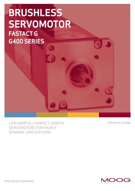
BRUSHLESS<br />
SERVOMOTOR<br />
FASTACT G<br />
G400 SERIES<br />
LOW INERTIA, COMPACT LENGTH<br />
SERVOMOTORS FOR HIGHLY<br />
DYNAMIC APPLICATIONS<br />
What Moves Your World<br />
version 1.0 | 10/2008
TABLE OF CONTENTS <strong>Moog</strong> | FASTACT G/G400 <strong>series</strong><br />
Whenever the highest levels of motion control performance<br />
and design flexibility are required, you’ll find <strong>Moog</strong> expertise<br />
at work. Through collaboration, creativity and world-class<br />
technological solutions, we help you overcome your toughest<br />
engineering obstacles. Enhance your machine performance.<br />
And help take your thinking further than you ever thought<br />
possible.<br />
OVERVIEW 2<br />
FEATuRES & BENEFITS 3<br />
PERFORMANCE SPECIFICATIONS 5<br />
INSTALLATION DIAGRAMS 6<br />
WIRING DIAGRAMS 22<br />
BEARING LOAD DIAGRAMS 24<br />
OPTIONS 26<br />
APPLICATION NOTE 28<br />
GENERAL INFO. & NOTES 32<br />
ORDERING INFORMATION 33<br />
Version .0 | 0/2008<br />
D E<br />
V<br />
24<br />
This catalog is for users with technical knowledge. To ensure that all necessary characteristics for function and safety of the system are given, the user has to check<br />
the suitability of the products described herein. The products described herein are subject to change without notice. In case of doubt, please contact <strong>Moog</strong>.<br />
For the most current information, visit www.moog.com/<strong>servomotor</strong>sanddrives<br />
<strong>Moog</strong> is a registered trademark of <strong>Moog</strong> <strong>Inc</strong>. and its subsidiaries. All trademarks as indicated herein are the property of <strong>Moog</strong> <strong>Inc</strong>. and its subsidiaries.<br />
©<strong>Moog</strong> <strong>Inc</strong>. 2008. All rights reserved. All changes are reserved.<br />
Dimensions in mm
OVERVIEW <strong>Moog</strong> | FASTACT G/G400 <strong>series</strong><br />
<strong>Moog</strong> Brushless Technology<br />
For over two decades, the name <strong>Moog</strong> has been associated<br />
with <strong>brushless</strong> servo motors and drives offering the<br />
highest dynamics, power density and reliability. The servo<br />
motors and drives are designed as a system to deliver<br />
superior servo performance. <strong>Moog</strong> offers a broad range of<br />
standard servo motors and drives as well as custom solutions<br />
to meet your unique application requirements. <strong>Moog</strong><br />
<strong>brushless</strong> servo motors and drives are found on a variety of<br />
applications; especially where dynamics, compact size and<br />
reliability are important.<br />
G400 Series Brushless Servomotors<br />
<strong>Moog</strong>’s G400 Series motors are electronically commutated<br />
synchronous AC motors with permanent magnet field<br />
excitation.<br />
G400 Series motors are designed for highly dynamic servo<br />
applications where positioning times of 30 msec or less<br />
are often the norm. The G400 Series offers one of the<br />
industry’s widest power ranges with standard models<br />
available at continuous torque ratings from 0. 5 to 76.6<br />
Nm ( .33 to 673 lb-in ). The modular design is supported by<br />
a variety of options with <strong>Moog</strong>’s application staff capable<br />
of supplying fully customized solutions. All <strong>Moog</strong> servo<br />
motors are manufactured in-house and the use of tight<br />
machining tolerances, precision balancing and thorough<br />
production testing guarantee a long service life.<br />
Ordering information and motor nameplate<br />
To order a motor, choose the various Type options by filling<br />
in the boxcar on the inside back page of the catalog. <strong>Moog</strong><br />
sales department will provide the corresponding Model<br />
number suitable for the order. Both model number and<br />
boxcar (Model and Type respectively, as in picture) will be<br />
present on the motor nameplate. The Type field may vary<br />
for motors released prior to June 2008.<br />
Version .0 | 0/2008<br />
<strong>Moog</strong> Motor Performance Characteristics<br />
In collaborating with a variety of industrial machine designers,<br />
<strong>Moog</strong> realizes what a critical role the application<br />
sizing process plays in overall machine design. With global<br />
competition forcing designers to do more with less, there<br />
is an ever-increasing need to avoid unnecessary margin<br />
and ”size” exactly to your application needs. It is for these<br />
reasons that <strong>Moog</strong> specifies motor performance characteristics<br />
in a manner that makes them practical for designing<br />
your system. Motor characteristics are specified under the<br />
same environmental conditions in which they will be used,<br />
with notes clearly articulating the operating conditions.<br />
The motor performance characteristic contains three<br />
elements.<br />
The first element is the continuous torque curve. This curve<br />
illustrates the motor torque available at 00% duty cycle<br />
under the following conditions:<br />
• operation in still air with ambient temperatures up to<br />
40°C<br />
• winding temperature at 0°C over ambient for resolver<br />
feedback motors<br />
• motor front flange attached to a steel mounting plate<br />
measuring 300 x 300 x 2 mm<br />
The second element is the peak torque curve. This curve<br />
reflects the motor torque available with a 10% duty cycle<br />
( out of 0 seconds). It is based on years of practical<br />
industry experience and is useful for typical servo applications.<br />
The third element is the motor Kt characteristic. The motor<br />
Kt characteristic depicts stator saturation at various operating<br />
points and can be used to optimize sizing in low duty<br />
cycle applications. G400 motors can deliver a low duty<br />
cycle “impulse torque” which is typically 20–30% more<br />
than rated peak torque. While motors can be operated<br />
reliably at this operating point it is recommended that a<br />
member of <strong>Moog</strong>’s application team review the application<br />
to ensure thermal restrictions are not violated.<br />
1 Continuous torque with<br />
1 12<br />
convection cooling<br />
3 2 Peak torque<br />
3 Motor Kt<br />
2
FEATuRES & BENEFITS <strong>Moog</strong> | FASTACT G/G400 <strong>series</strong><br />
Superior Motor Dynamics Improves Cycle Time<br />
The G400 Series motor combines a low inertia rotor with<br />
an electromagnetic design having exceptional overload<br />
capacity. The result is an increase in the effective torque<br />
available to accelerate and decelerate the load, enabling<br />
higher dynamics and improved cycle times.<br />
G400 Series motors use a fully laminated, weight-optimized,<br />
rotor to provide a significant inertia reduction over<br />
conventional solid rotor designs. It is able to achieve a high<br />
overload capacity through the use of high-energy rare magnets,<br />
a high pole count electrical design, and an efficient<br />
thermal construction.<br />
Compact, Lightweight, Construction Simplifies<br />
Machine Design<br />
The G400 Series motor provides high torque in a compact,<br />
lightweight, package to achieve both high power density<br />
and a high torque-to-weight ratio. The compact, lightweight,<br />
package provides greater flexibility and often<br />
enables new cost-saving approaches to machine construction.<br />
In applications where the motor is mounted on a<br />
moving axis the high torque to weight ratio allows greater<br />
payloads and/or increased acceleration.<br />
G400 Series motors leverage an all aluminum motor<br />
housing to achieve a significant weight reduction over low<br />
cost<br />
steel housings. A robust thermal design allows more power<br />
to be designed into a small, compact, package.<br />
Proprietary, Low-Cogging, Design Delivers Smooth<br />
Low Speed Operation<br />
The G400 Series motor includes several design enhancements<br />
to deliver smooth slow speed performance. The<br />
enhancements include the selection of a high pole count<br />
(8 to 2 poles) electromagnetic design, a stator with nonsymmetric<br />
slot count and other proprietary features to<br />
minimize cogging.<br />
1<br />
Motor with Encoder 1 Cutaway Diagram<br />
2<br />
2<br />
3<br />
3<br />
1<br />
4<br />
4<br />
2<br />
5<br />
1<br />
5<br />
3<br />
6<br />
2<br />
6<br />
4<br />
7<br />
7<br />
1<br />
3<br />
5<br />
8<br />
1<br />
8<br />
2<br />
4<br />
2<br />
1<br />
6<br />
1 3<br />
5<br />
3<br />
2<br />
7<br />
2 4<br />
6<br />
4<br />
3<br />
8<br />
3 5<br />
7<br />
5<br />
4<br />
4 6<br />
8<br />
6<br />
5<br />
5 7<br />
7<br />
6<br />
6 8<br />
8<br />
7<br />
1 11<br />
1 Metal CE/uL compliant connectors<br />
8<br />
7<br />
2 Proprietary stator design<br />
8<br />
3 Rare earth magnets<br />
4 Sealed life-time lubricated bearings<br />
5<br />
Version .0 6 6|<br />
0/2008<br />
7<br />
Ruggedized, Maintenance-Free, Design to Boost<br />
Overall System Availability<br />
The G400 Series motor is designed and manufactured in<br />
accordance with strict CE (VDE) standards, using ruggedized<br />
components with proven reliability in harsh thermal<br />
and shock load environments. These all combine to offer<br />
years of reliable, maintenance-free, operation and boost<br />
overall system availability.<br />
The use of high reliability feedback devices, sealed lifetime<br />
lubricated bearings, precision balanced rotors (Class<br />
G 6.3 of ISO 940), reduced runout machining tolerances<br />
(Class R of DIN 42955-R) and IP65 construction combine<br />
to extend service life.<br />
Flexible Design Option Ease Integration<br />
The G400 Series motor is available with the following<br />
options:<br />
• Integral holding brakes<br />
• Resolver or encoder based feedback<br />
• Plain or slot & key type shafts<br />
• Teflon shaft seal (IP67 sealing)<br />
• Convection (standard) or fan cooling (upon request)<br />
Fully Customized Designs Support Unique<br />
Application Requirements<br />
Finally, our G400 Series motors can be customized to meet<br />
your unique needs.<br />
The following are typical requests supported by <strong>Moog</strong>’s<br />
application staff:<br />
• Custom motor windings<br />
• Custom shafts and flanges<br />
• Custom frameless designs<br />
• Custom connector configurations (including pigtails)<br />
• Custom feedback devices<br />
• Custom designs for unique environments including high<br />
temperature, high shock levels, oil and water immersion,<br />
areas with explosive gases and areas with elevated radi-<br />
ation levels.<br />
Motor with Resolver Cutaway Diagram<br />
1<br />
1<br />
2<br />
1<br />
2<br />
3<br />
2<br />
3<br />
4<br />
3<br />
4<br />
5<br />
4<br />
1<br />
5<br />
1 6<br />
51<br />
2 6<br />
2 7<br />
62<br />
3 1 7<br />
3 8<br />
73<br />
4 2 8<br />
1<br />
4<br />
3<br />
2 84<br />
5<br />
5<br />
4<br />
3 5<br />
1<br />
6<br />
6<br />
2<br />
5<br />
4 6<br />
7<br />
3 37<br />
6<br />
5 7<br />
8<br />
4 48<br />
7<br />
6 8<br />
5 Lightweight extruded aluminum housing<br />
8<br />
7<br />
6 Fully laminated low-inertia rotor<br />
8<br />
7 7 Optional holding brake<br />
8 High reliability device feedback<br />
3
TECHNICAL DATA <strong>Moog</strong> | FASTACT G/G400 <strong>series</strong><br />
Version .0 | 0/2008<br />
4
TECHNICAL DATA <strong>Moog</strong> | FASTACT G/G400 <strong>series</strong><br />
G-1-M2 (L20)<br />
G-1-M6 (L60)<br />
Version .0 | 0/2008<br />
Performance Specifications For Standard Type: G-1-M (Low Voltage)<br />
Characteristics and nominal values with sinusoidal drive<br />
Type G-1-M2 (L20) G-1-M4 (L40) G-1-M6 (L60) Units<br />
Nominal Torque. continuous duty, locked rotor Mo 0. 5 [ .3] 0.27 [2.4] 0.37 [3.3] Nm [lb-in]<br />
Nominal Torque, continuous duty, nominal speed MN 0. 4 [ .2] 0.24 [2. ] 0.30 [2.7] Nm [lb-in]<br />
Max torque Mmax 0.5 [4.4] [8.9] .5 [ 3.3] Nm [lb-in]<br />
Nominal speed nN 9000 6000 6000 rpm<br />
Maximum speed nmax 4000 2000 9000 rpm<br />
Nominal current, locked rotor lo 0.87 0.78 0.8 Arms<br />
Peak current I p 3.3 3.3 3.7 Arms<br />
Output power, continuous duty, nominal speed PN 0. 3 [ 0. 8] 0. 5 [0.20] 0. 9 [0.25] kW [hp]<br />
Torque constant kT 0. 7 [ .5] 0.34 [3.0] 0.46 [4. ] Nm/Arms [lb-in/Arms]<br />
Voltage constant ke 22. 29.6 Vrms/krpm<br />
Thermal time constant τTh 350 500 650 sec<br />
Winding resistance at 25°C (phase to phase) Rtt 23.0 34.8 37.0 Ohm<br />
Winding inductance (phase to phase) Ltt 5.2 0.4 2.4 mH<br />
Rotor inertia with resolver J 0.027 [0.24] 0.049 [0.43] 0.072 [0.64] kg cm 2 [lb-insec 2 x 0 -4 ]<br />
Rotor inertia with encoder J 0.023 [0.2] 0.045 [0.4] 0.068 [0.6] kg cm 2 [lb-insec 2 x 0 -4 ]<br />
Weight (without brake) m 0.55 [ .2] 0.68 [ .5] 0.82 [ .8] kg [lb]<br />
Optional Holding Brake Option 1 Option 2 Units<br />
Holding torque 0.4 [3.5] N/A Nm [lb-in]<br />
Extra weight 0.06 [0. 3] N/A kg [lb]<br />
Extra inertia with resolver 0.0 [0.09] N/A kg cm 2 [lb-insec 2 x 0 -4 ]<br />
Extra inertia with encoder 0.0 [0.09] N/A kg cm 2 [lb-insec 2 x 0 -4 ]<br />
Power requirement 6.0 N/A Watt<br />
Voltage requirement (+ 0% - 0%) 24 N/A V DC<br />
G-1-M4 (L40)<br />
Notes:<br />
. Motor performances as measured with <strong>Moog</strong>‘s servodrive of<br />
proper size<br />
2. Motor pole count: 8<br />
3. G-X-M: 325 V DC link<br />
For a complete list of options and accessories, see pages 26–27.<br />
1 Continuous torque with<br />
1 12<br />
convection cooling<br />
3 2 Peak torque<br />
3 Motor Kt<br />
5
TECHNICAL DATA <strong>Moog</strong> | FASTACT G/G400 <strong>series</strong><br />
G-2-M2 (L05)<br />
0<br />
4,0<br />
3,6<br />
3,2<br />
2,8<br />
2,4<br />
2,0<br />
1,6<br />
1,2<br />
0,8<br />
0,4<br />
Version .0 | 0/2008<br />
Performance Specifications For Standard Type: G-2-M (Low Voltage)<br />
Characteristics and nominal values with sinusoidal drive<br />
Type G-2-M2 (L05) G-2-M4 (L10) G-2-M6 (L20) G-2-M8 (L40) Units<br />
Nominal Torque. continuous duty, locked rotor Mo 0.25 [2.2] 0.5 [4.4] 0.95 [8.4] .7 [ 5.0] Nm [lb-in]<br />
Nominal Torque, continuous duty, nominal speed MN 0. 8 [ .6] 0.42[3.7] 0.74 [6.6] .3 [ .2] Nm [lb-in]<br />
Max torque Mmax 0.8 [7. ] .6 [ 4.2] 3. [27.4] 6.2 [54.9] Nm [lb-in]<br />
Nominal speed nN 8 00 7400 6800 6200 rpm<br />
Maximum speed nmax 500 0000 9000 7000 rpm<br />
Nominal current, locked rotor lo 0.65 .2 2. 5 2.85 Arms<br />
Peak current I p 2.4 4.3 7.5 2 Arms<br />
Output power, continuous duty, nominal speed PN 0. 5 [0.20] 0.33 [0.44] 0.53 [0.7 ] 0.82 [ . 0] kW [hp]<br />
Torque constant kT 0.37 [3.3] 0.42[3.7] 0.46[4. ] 0.60[5.3] Nm/Arms [lb-in/Arms]<br />
Voltage constant ke 23.4 26.0 35.6 35.58 Vrms/krpm<br />
Thermal time constant τTh 245 4 5 5 4 926 sec<br />
Winding resistance at 25°C (phase to phase) Rtt 50.9 20.7 9.9 6.3 Ohm<br />
Winding inductance (phase to phase) Ltt 29.7 5.7 9. 7.2 mH<br />
Rotor inertia with resolver J 0.09 [0.8] 0. 3 [ .2] 0.22 [ .9] 0.4 [3.6] kg cm 2 [lb-insec 2 x 0 -4 ]<br />
Rotor inertia with encoder J 0.07 [0.62] 0. [ .0] 0.20 [ .8] 0.39 [3.5] kg cm 2 [lb-insec 2 x 0 -4 ]<br />
Weight (without brake) m [2.2] .2 [2.6] .5 [3.3] 2.3 [5. ] kg [lb]<br />
Optional Holding Brake Option 1 Option 2 Units<br />
Holding torque .0 [8.9] N/A Nm [lb-in]<br />
Extra weight 0. 2 [0.26] N/A kg [lb]<br />
Extra inertia with resolver 0.02 [0. 8] N/A kg cm 2 [lb-insec 2 x 0 -4 ]<br />
Extra inertia with encoder 0.02 [0. 8] N/A kg cm 2 [lb-insec 2 x 0 -4 ]<br />
Power requirement 0.0 N/A Watt<br />
Voltage requirement (+6% - 0%) 24 N/A V DC<br />
G-2-M6 (L20)<br />
Torque (Nm)<br />
0<br />
Current (Arms)<br />
1 2 3 4 5 6 7 8<br />
35,4<br />
31,9<br />
28,3<br />
24,8<br />
21,2<br />
17,7<br />
14,2<br />
10,6<br />
7,1<br />
3,5<br />
0<br />
1000 2000 3000 4000 5000 6000 7000 8000<br />
Speed (rpm)<br />
Torque (lb-ln)<br />
G-2-M4 (L10)<br />
G-2-M8 (L40)<br />
Notes:<br />
. Motor performances as measured with <strong>Moog</strong>‘s servodrive of<br />
proper size<br />
2. Motor pole count: 8<br />
3. G-X-M: 325 V DC link<br />
For a complete list of options and accessories, see pages 26–27<br />
1 Continuous torque with<br />
1 12<br />
convection cooling<br />
3 2 Peak torque<br />
3 Motor Kt<br />
6
TECHNICAL DATA <strong>Moog</strong> | FASTACT G/G400 <strong>series</strong><br />
G-2-V2 (L05)<br />
G-2-V6 (L20)<br />
Torque (Nm)<br />
0<br />
4,0<br />
3,6<br />
3,2<br />
2,8<br />
2,4<br />
2,0<br />
1,6<br />
1,2<br />
0,8<br />
0,4<br />
Version .0 | 0/2008<br />
Performance Specifications For Standard Type: G-2-V (High Voltage)<br />
Characteristics and nominal values with sinusoidal drive<br />
Type G-2-V2 (L05) G-2-V4 (L10) G-2-V6 (L20) G-2-V8 (L40) Units<br />
Nominal Torque. continuous duty, locked rotor Mo 0.25 [2.2] 0.5 [4.4] .0 [8.9] 2.0 [ 7.7] Nm [lb-in]<br />
Nominal Torque, continuous duty, nominal speed MN 0. 8 [ .6] 0.29 [2.6] 0.65 [5.7] .0 [8.5] Nm [lb-in]<br />
Max torque Mmax 0.8 [7. ] .6 [ 4.2] 3. [27.4] 6.2 [54.9] Nm [lb-in]<br />
Nominal speed nN 9000 9000 7500 7500 rpm<br />
Maximum speed nmax 500 500 000 000 rpm<br />
Nominal current, locked rotor lo 0.63 .26 .56 2.94 Arms<br />
Peak current I p 2.2 4.3 5.3 0.6 Arms<br />
Output power, continuous duty, nominal speed PN 0. 7 [0.23] 0.27 [0.37] 0.5 [0.68] 0.75 [ .0 ] kW [hp]<br />
Torque constant kT 0.40 [3.5] 0.40 [3.5] 0.64 [5.7] 0.68 [6.0] Nm/Arms [lb-in/Arms]<br />
Voltage constant ke 25.9 25.4 40.0 39.8 Vrms/krpm<br />
Thermal time constant τTh 245 4 5 5 4 926 sec<br />
Winding resistance at 25°C (phase to phase) Rtt 60.7 20.0 9.2 7.9 Ohm<br />
Winding inductance (phase to phase) Ltt 33.9 5.0 7.9 8.7 mH<br />
Rotor inertia with resolver J 0.09 [0.80] 0. 3 [ .2] 0.22 [ .9] 0.4 [3.6] kg cm 2 [lb-insec 2 x 0 -4 ]<br />
Rotor inertia with encoder J 0.07 [0.62] 0. [ .0] 0.20 [ .8] 0.39 [3.5] kg cm 2 [lb-insec 2 x 0 -4 ]<br />
Weight (without brake) m .0 [2.2] .2 [2.6] .5 [3.3] 2.3 [5. ] kg [lb]<br />
Optional Holding Brake Option 1 Option 2 Units<br />
Holding torque .0 [8.9] N/A Nm [lb-in]<br />
Extra weight 0. 2 [0.26] N/A kg [lb]<br />
Extra inertia with resolver 0.02 [0. 8] N/A kg cm 2 [lb-insec 2 x 0 -4 ]<br />
Extra inertia with encoder 0.02 [0. 8] N/A kg cm 2 [lb-insec 2 x 0 -4 ]<br />
Power requirement 0.0 N/A Watt<br />
Voltage requirement (+6% - 0%) 24 N/A V DC<br />
0<br />
Current (Arms)<br />
1 2 3 4 5 6 7 8 9<br />
35,4<br />
31,9<br />
28,3<br />
24,8<br />
21,2<br />
17,7<br />
14,2<br />
10,6<br />
7,1<br />
3,5<br />
0<br />
1000 2000 3000 4000 5000 6000 7000 8000 9000<br />
Speed (rpm)<br />
Torque (lb-ln)<br />
G-2-V4 (L10)<br />
G-2-V8 (L40)<br />
Torque (Nm)<br />
0<br />
8,0<br />
7,2<br />
6,4<br />
5,6<br />
4,8<br />
4,0<br />
3,2<br />
2,4<br />
1,6<br />
0,8<br />
0<br />
Current (Arms)<br />
1,5 3,0 4,5 6,0 7,5 9,0 10,5 12,5 13,5<br />
70,8<br />
63,7<br />
56,6<br />
49,6<br />
42,5<br />
35,4<br />
28,3<br />
21,2<br />
14,2<br />
7,1<br />
0<br />
1000 2000 3000 4000 5000 6000 7000 8000 9000<br />
Speed (rpm)<br />
Notes:<br />
. Motor performances as measured with <strong>Moog</strong>‘s servodrive of<br />
proper size<br />
2. Motor pole count: 8<br />
3. G-X-M: 565 V DC link<br />
For a complete list of options and accessories, see pages 26–27.<br />
Torque (lb-ln)<br />
1 Continuous torque with<br />
1 12<br />
convection cooling<br />
3 2 Peak torque<br />
3 Motor Kt<br />
7
TECHNICAL DATA <strong>Moog</strong> | FASTACT G/G400 <strong>series</strong><br />
G-3-M2 (L05)<br />
G-3-M6 (L25)<br />
Version .0 | 0/2008<br />
Performance Specifications For Standard Type: G-3-M (Low Voltage)<br />
Characteristics and nominal values with sinusoidal drive<br />
Type G-3-M2 (L05) G-3-M4 (L15) G-3-M6 (L25) G-3-M8 (L40) Units<br />
Nominal Torque. continuous duty, locked rotor Mo 0.6 [5.3] .65 [ 4.6] 2.55 [22.6] 3.7 [32.7] Nm [lb-in]<br />
Nominal Torque, continuous duty, nominal speed MN 0.49 [4.3] .4 [ 2.7] 2.3 [20.3] 3.4 [30.3] Nm [lb-in]<br />
Max torque Mmax .7 [ 5.0] 5.0 [44.3] 8.3 [73.5] 3. [ 5.9] Nm [lb-in]<br />
Nominal speed nN 8800 6300 4800 3900 rpm<br />
Maximum speed nmax 0500 8000 5500 4500 rpm<br />
Nominal current, locked rotor lo .6 3.2 3.4 4.2 Arms<br />
Peak current I p 5 .5 3 7 Arms<br />
Output power, continuous duty, nominal speed PN 0.45 [0.6] 0.95 [ .3] .2 [ .5] .4 [ .9] kW [hp]<br />
Torque constant kT 0.40 [3.5] 0.53 [4.7] 0.75 [6.6] 0.90 [8.0] Nm/Arms [lb-in/Arms]<br />
Voltage constant ke 25 3 .6 45.7 55.3 Vrms/krpm<br />
Thermal time constant τTh 333 758 967 345 sec<br />
Winding resistance at 25°C (phase to phase) Rtt 5.2 4.9 5. 4. Ohm<br />
Winding inductance (phase to phase) Ltt 8.8 8.5 0.3 8.9 mH<br />
Rotor inertia with resolver J 0. 6 [ .4] 0.39 [3.5] 0.62 [5.5] 0.97 [8.6] kg cm 2 [lb-insec 2 x 0 -4 ]<br />
Rotor inertia with encoder J 0. 4 [ .2] 0.37 [3.3] 0.60 [5.3] 0.95 [8.4] kg cm 2 [lb-insec 2 x 0 -4 ]<br />
Weight (without brake) m .4 [3. ] 2.0 [4.4] 2.6 [5.7] 3.5 [7.7] kg [lb]<br />
Optional Holding Brake Option 1 Option 2 Units<br />
Holding torque 2.0 [ 7.7] 4.5 [39.8] Nm [lb-in]<br />
Extra weight 0.20 [0.44] 0.32 [2.8] kg [lb]<br />
Extra inertia with resolver 0.07 [0.62] 0. 8 [ .6] kg cm 2 [lb-insec 2 x 0 -4 ]<br />
Extra inertia with encoder 0.07 [0.62] 0. 8 [ .6] kg cm 2 [lb-insec 2 x 0 -4 ]<br />
Power requirement .0 2.0 Watt<br />
Voltage requirement (+6% - 0%) 24 24 V DC<br />
G-3-M4 (L15)<br />
G-3-M8 (L40)<br />
Notes:<br />
. Motor performances as measured with <strong>Moog</strong>‘s servodrive of<br />
proper size<br />
2. Motor pole count: 8<br />
3. G-X-M: 325 V DC link<br />
For a complete list of options and accessories, see pages 26–27.<br />
1 Continuous torque with<br />
1 12<br />
convection cooling<br />
3 2 Peak torque<br />
3 Motor Kt<br />
8
TECHNICAL DATA <strong>Moog</strong> | FASTACT G/G400 <strong>series</strong><br />
G-3-V2 (L05)<br />
G-3-V6 (L25)<br />
Version .0 | 0/2008<br />
Performance Specifications For Standard Type: G-3-V (High Voltage)<br />
Characteristics and nominal values with sinusoidal drive<br />
Type G-3-V2 (L05) G-3-V4 (L15) G-3-V6 (L25) G-3-V8 (L40) Units<br />
Nominal Torque. continuous duty, locked rotor Mo 0.6 [5.3] .6 [ 4.2] 2.5 [22. ] 3.8 [33.6] Nm [lb-in]<br />
Nominal Torque, continuous duty, nominal speed MN 0.54 [4.8] .4 [ 2.7] 2.2 [ 9.5] 3. [27.9] Nm [lb-in]<br />
Max torque Mmax .7 [ 5.0] 5 [44.3] 8.3 [73.5] 3. [ 5.9] Nm [lb-in]<br />
Nominal speed nN 8700 6200 4800 4700 rpm<br />
Maximum speed nmax 0500 0000 6000 5600 rpm<br />
Nominal current, locked rotor lo .3 2.3 2. 3.0 Arms<br />
Peak current I p 4. 8.3 8.3 2.5 Arms<br />
Output power, continuous duty, nominal speed PN 0.49 [0.7] 0.94 [ .3] . [ .5] .6 [2. ] kW [hp]<br />
Torque constant kT 0.48 [4.2] 0.7 [6.3] . 9 [ 0.5] .27 [ .2] Nm/Arms [lb-in/Arms]<br />
Voltage constant ke 30.5 43.4 7 .8 76. Vrms/krpm<br />
Thermal time constant τTh 333 758 967 345 sec<br />
Winding resistance at 25°C (phase to phase) Rtt 24.6 9.5 3.0 8. Ohm<br />
Winding inductance (phase to phase) Ltt 29.0 6. 25.0 7.0 mH<br />
Rotor inertia with resolver J 0. 6 [ .4] 0.39 [3.5] 0.62 [5.5] 0.97 [8.6] kg cm 2 [lb-insec 2 x 0 -4 ]<br />
Rotor inertia with encoder J 0. 4 [ .2] 0.37 [3.3] 0.60 [5.3] 0.95 [8.4] kg cm 2 [lb-insec 2 x 0 -4 ]<br />
Weight (without brake) m .4 [3. ] 2.0 [4.4] 2.6 [5.7] 3.5 [7.7] kg [lb]<br />
Optional Holding Brake Option 1 Option 2 Units<br />
Holding torque 2.0 [ 7.7] 4.5 [39.8] Nm [lb-in]<br />
Extra weight 0.20 [0.44] 0.32 [2.8] kg [lb]<br />
Extra inertia with resolver 0.07 [0.62] 0. 8 [ .6] kg cm 2 [lb-insec 2 x 0 -4 ]<br />
Extra inertia with encoder 0.07 [0.62] 0. 8 [ .6] kg cm 2 [lb-insec 2 x 0 -4 ]<br />
Power requirement .0 2.0 Watt<br />
Voltage requirement (+6% - 0%) 24 24 V DC<br />
G-3-V4 (L15)<br />
G-3-V8 (L40)<br />
Notes:<br />
. Motor performances as measured with <strong>Moog</strong>‘s servodrive of<br />
proper size<br />
2. Motor pole count: 8<br />
3. G-X-M: 565 V DC link<br />
For a complete list of options and accessories, see pages 26–27.<br />
1 Continuous torque with<br />
1 12<br />
convection cooling<br />
3 2 Peak torque<br />
3 Motor Kt<br />
9
TECHNICAL DATA <strong>Moog</strong> | FASTACT G/G400 <strong>series</strong><br />
G-4-M2 (L05)<br />
G-4-M8 (L40)<br />
30<br />
25<br />
20<br />
15<br />
10<br />
Version .0 | 0/2008<br />
Performance Specifications For Standard Type: G-4-M (Low Voltage)<br />
Characteristics and nominal values with sinusoidal drive<br />
Type G-4-M2 (L05) G-4-M4 (L10) G-4-M6 (L20) G-4-M8 (L40) G-4-M9 (L60) Units<br />
Nominal Torque. continuous duty, locked rotor Mo .3 [ .5] 2.6 [23.0] 4.7 [4 .6] 8.2 [72.6] 2.5 [ 0.6] Nm [lb-in]<br />
Nominal Torque, continuous duty, nominal speed MN .0 [8.5] .6 [ 4.6] 4.0 [35.4] 6.3 [55.6] 9.2 [8 .5] Nm [lb-in]<br />
Max torque Mmax 3.3 [29.2] 6.6 [58.4] 3.2 [ 6.8] 26.5 [234.5] 39.8 [352.3] Nm [lb-in]<br />
Nominal speed nN 5800 5500 4300 3500 2800 rpm<br />
Maximum speed nmax 0000 8000 5800 4700 3280 rpm<br />
Nominal current, locked rotor lo 3. 4.8 6.7 9.2 9.6 Arms<br />
Peak current I p 9.5 5 23 37.5 42.8 Arms<br />
Output power, continuous duty, nominal speed PN 0.58 [0.8] 0.95 [ .3] .8 [2.4] 2.3 [3. ] 2.7 [3.6] kW [hp]<br />
Torque constant kT 0.42 [3.7] 0.56 [5.0] 0.70 [6.2] 0.89 [7.9] .30 [ .5] Nm/Arms [lb-in/Arms]<br />
Voltage constant ke 27.0 34.2 43. 52.9 69.3 Vrms/krpm<br />
Thermal time constant τTh 703 00 475 8 2 2000 sec<br />
Winding resistance at 25°C (phase to phase) Rtt 5. 0 2.70 .50 0.90 .00 Ohm<br />
Winding inductance (phase to phase) Ltt 8.5 5.8 4.6 3.5 4.0 mH<br />
Rotor inertia with resolver J .05 [9.3] .55 [ 3.7] 2.6 [23.0] 4.7 [4 .6] 6.8 [60.2] kg cm 2 [lb-insec 2 x 0 -4 ]<br />
Rotor inertia with encoder J 0.85 [7.5] .4 [ .9] 2.4 [2 .2] 4.5 [39.8] 6.6 [58.4] kg cm 2 [lb-insec 2 x 0 -4 ]<br />
Weight (without brake) m 3.0 [6.6] 3.6 [7.9] 4.7 [ 0.4] 6.9 [ 5.2] 9. [20. ] kg [lb]<br />
Optional Holding Brake Option 1 Option 2 Units<br />
Holding torque 9.0 [79.7] 8.0 [ 59] a) Nm [lb-in]<br />
Extra weight 0.53 [ .2] 0.75 [6.6] kg [lb]<br />
Extra inertia with resolver 0.54 [4.8] .0 [8.9] kg cm 2 [lb-insec 2 x 0 -4 ]<br />
Extra inertia with encoder 0.6 [5.4] . [9.5] kg cm 2 [lb-insec 2 x 0 -4 ]<br />
Power requirement 8.0 5.6 Watt<br />
Voltage requirement (+6% - 0%) 24 24 V DC<br />
5<br />
0<br />
G-4-M4 (L10)<br />
G-4-M9 (L60)<br />
Notes:<br />
. Motor performances as measured with <strong>Moog</strong>‘s servodrive of<br />
proper size<br />
2. Motor pole count: 2<br />
3. G-X-M: 325 V DC link<br />
a) with encoder holding torque 4.5 Nm ( 28.5 lb)<br />
For a complete list of options and accessories, see pages 26–27.<br />
G-4-M6 (L20)<br />
1 Continuous torque with<br />
1 12<br />
convection cooling<br />
3 2 Peak torque<br />
3 Motor Kt<br />
0
TECHNICAL DATA <strong>Moog</strong> | FASTACT G/G400 <strong>series</strong><br />
G-4-V2 (L05)<br />
G-4-V8 (L40)<br />
Version .0 | 0/2008<br />
Performance Specifications For Standard Type: G-4-V (High Voltage)<br />
Characteristics and nominal values with sinusoidal drive<br />
Type G-4-V2 (L05) G-4-V4 (L10) G-4-V6 (L20) G-4-V8 (L40) G-4-V9 (L60) Units<br />
Nominal Torque. continuous duty, locked rotor Mo .5 [ 3.3] 2.9 [25.7] 5.0 [44.0] 8.3 [73.7] .2 [99. ] Nm [lb-in]<br />
Nominal Torque, continuous duty, nominal speed MN . [9.8] 2.3 [20.0] 3.8 [33.8] 6.3 [55.3] 8. [7 .9] Nm [lb-in]<br />
Max torque Mmax 3.3 [29.2] 6.6 [58.4] 3.2 [ 6.8] 26.5 [234.5] 39.8 [352.3] Nm [lb-in]<br />
Nominal speed nN 7800 5500 4200 3300 3000 rpm<br />
Maximum speed nmax 0000 0000 6300 5000 3600 rpm<br />
Nominal current, locked rotor lo 3.0 4.9 4.3 5.8 5.6 Arms<br />
Peak current Ip 8, 3,6 4,3 23 25 Arms<br />
Output power, continuous duty, nominal speed PN 0.90 [ .2] .30 [ .7] .7 [2.3] 2.2 [2.9] 2.6 [3.4] kW [hp]<br />
Torque constant kT 0.50 [4.4] 0.60 [5.3] . 5 [ 0. ] .43 [ 2.7] .99 [ 7.6] Nm/Arms [lb-in/Arms]<br />
Voltage constant ke 32,2 37,6 69,7 85,9 8,7 Vrms/krpm<br />
Thermal time constant τTh 703 00 475 8 2 2000 sec<br />
Winding resistance at 25°C (phase to phase) Rtt 6.70 2.83 3.80 2.40 2.84 Ohm<br />
Winding inductance (phase to phase) Ltt 2.0 7. .8 9.4 0.6 mH<br />
Rotor inertia with resolver J .05 [9.3] .55 [ 3.7] 2.6 [23.0] 4.7 [4 .6] 6.8 [60.2] kg cm2 [lb-insec 2 x 0-4 ]<br />
Rotor inertia with encoder J 0.85 [7.5] .4 [ .9] 2.4 [2 .2] 4.5 [39.8] 6.6 [58.4] kg cm2 [lb-insec 2 x 0-4 ]<br />
Weight (without brake) m 3.0 [6.6] 3.6 [7.9] 4.7 [ 0.4] 6.9 [ 5.2] 9. [20. ] kg [lb]<br />
Optional Holding Brake Option 1 Option 2 Units<br />
Holding torque 9.0 [79.7] 8.0 [ 59] a) Nm [lb-in]<br />
Extra weight 0.53 [ .2] 0.75 [6.6] kg [lb]<br />
Extra inertia with resolver 0.54 [4.8] .0 [8.9] kg cm2 [lb-insec 2 x 0-4 ]<br />
Extra inertia with encoder 0.6 [5.4] . [9.5] kg cm2 [lb-insec 2 x 0-4 ]<br />
Power requirement 8.0 5.6 Watt<br />
Voltage requirement (+6% - 0%) 24 24 VDC G-4-V4 (L10)<br />
G-4-V9 (L60)<br />
Notes:<br />
. Motor performances as measured with <strong>Moog</strong>‘s servodrive of<br />
proper size<br />
2. Motor pole count: 2<br />
3. G-X-M: 565 V DC link<br />
a) with encoder holding torque 4.5 Nm ( 28.5 lb)<br />
For a complete list of options and accessories, see pages 26–27<br />
G-4-V6 (L20)<br />
1 Continuous torque with<br />
1 12<br />
convection cooling<br />
3 2 Peak torque<br />
3 Motor Kt
TECHNICAL DATA <strong>Moog</strong> | FASTACT G/G400 <strong>series</strong><br />
G-5-M2 (L10) G-5-M4 (L20)<br />
G-5-M6 (L30)<br />
Version .0 | 0/2008<br />
Performance Specifications For Standard Type: G-5-M (Low Voltage)<br />
Characteristics and nominal values with sinusoidal drive<br />
Type G-5-M2 (L10) G-5-M4 (L20) G-5-M6 (L30) G-5-M8 (L50) G-5-M9 (L70) Units<br />
Nominal Torque. continuous duty, locked rotor Mo 5.8 [5 .3] .2 [99. ] 6.6 [ 46.9] 25 [22 .3] 36 [3 8.6] Nm [lb-in]<br />
Nominal Torque, continuous duty, nominal speed MN 4.6 [40.5] 9.3 [82. ] 4. [ 25.2] 20.0 [ 76.8] 26.8 [237. ] Nm [lb-in]<br />
Max torque Mmax 3.5 [ 9] 27.0 [239] 40.5 [358] 67.5 [597] 94.5 [836] Nm [lb-in]<br />
Nominal speed nN 4800 3500 2700 2200 2200 rpm<br />
Maximum speed nmax 6800 4200 3300 2400 2500 rpm<br />
Nominal current, locked rotor lo 9.5 .0 2.9 4.8 22. Arms<br />
Peak current I p 28.8 35.6 42 5 .5 77. Arms<br />
Output power, continuous duty, nominal speed PN 2.3 [3. ] 3.4 [4.6] 4.0 [5.4] 4.6 [6.2] 6.2 [8.3] kW [hp]<br />
Torque constant kT 0.6 [5.4] .02 [9.0] .29 [ .4] .69 [ 5.0] .63 [ 4.4] Nm/Arms [lb-in/Arms]<br />
Voltage constant ke 38.4 60.7 76.8 04.4 97. Vrms/krpm<br />
Thermal time constant τTh 587 2 96 2539 3292 3700 sec<br />
Winding resistance at 25°C (phase to phase) Rtt 0.86 0.74 0.64 0.56 0.3 Ohm<br />
Winding inductance (phase to phase) Ltt 4.3 4.8 4.8 4.8 3.5 mH<br />
Rotor inertia with resolver J 4.6 [40.7] 8 [70.8] .5 [ 0 .8] 8.4 [ 62.9] 25.3 [223.9] kg cm 2 [lb-insec 2 x 0 -4 ]<br />
Rotor inertia with encoder J 4.4 [38.9] 7.8 [69.0] .3 [ 00] 8.2 [ 6 ] 25. [222] kg cm 2 [lb-insec 2 x 0 -4 ]<br />
Weight (without brake) m 7.7 [ 7.0] 9.9 [2 .8] 2. [26.7] 6.6 [36.6] 2 [46.3] kg [lb]<br />
Optional Holding Brake Option 1 Option 2 Units<br />
Holding torque 8.0 [ 59]] 30.0 [266] Nm [lb-in]<br />
Extra weight 0.75 [ .7] . [9.7] kg [lb]<br />
Extra inertia with resolver .0 [8.9] 3.6 [3 .9] kg cm 2 [lb-insec 2 x 0 -4 ]<br />
Extra inertia with encoder .2 [ 0.4] 3.8 [33.4] kg cm 2 [lb-insec 2 x 0 -4 ]<br />
Power requirement 5.6 7.0 Watt<br />
Voltage requirement (+6% - 0%) 24 24 V DC<br />
G-5-M8 (L50) G-5-M9 (L70)<br />
10 20 30 40 50<br />
Notes:<br />
. Motor performances as measured with <strong>Moog</strong>‘s servodrive of<br />
proper size<br />
2. Motor pole count: 2<br />
3. G-X-M: 325 V DC link<br />
For a complete list of options and accessories, see pages 26–27<br />
1 Continuous torque with<br />
1 12<br />
convection cooling<br />
3 2 Peak torque<br />
3 Motor Kt<br />
2
TECHNICAL DATA <strong>Moog</strong> | FASTACT G/G400 <strong>series</strong><br />
G-5-V2 (L10)<br />
G-5-V8 (L50)<br />
Version .0 | 0/2008<br />
Performance Specifications For Standard Type: G-5-V (High Voltage)<br />
Characteristics and nominal values with sinusoidal drive<br />
Type G-5-V2 (L10) G-5-V4 (L20) G-5-V6 (L30) G-5-V8 (L50) G-5-V9 (L70) Units<br />
Nominal Torque. continuous duty, locked rotor Mo 6. [54.0] .4 [ 00.9] 6.7 [ 47.5] 26.3 [232.5] 35.2 [3 .5] Nm [lb-in]<br />
Nominal Torque, continuous duty, nominal speed MN 4.7 [4 .2] 8. [7 .9] .8 [ 04.7] 8.8 [ 66.4] 27.4 [242. ] Nm [lb-in]<br />
Max torque Mmax 3.5 [ 9.5] 27 [239.0] 40.5 [358.5] 67.5 [597.4] 94.5 [836.4] Nm [lb-in]<br />
Nominal speed nN 4800 4000 3400 2800 2200 rpm<br />
Maximum speed nmax 6500 4900 5200 4000 2900 rpm<br />
Nominal current, locked rotor lo 5.5 7.8 2.0 5.0 4.5 Arms<br />
Peak current I p 6 24.5 38.5 5 .5 5 .5 Arms<br />
Output power, continuous duty, nominal speed PN 2.3 [3. ] 3.4 [4.6] 4.2 [5.5] 5.5 [7.4] 6.3 [8.4] kW [hp]<br />
Torque constant kT . 2 [9.9] .47 [ 3.0] .39 [ 2.3] .75 [ 5.5] 2.45 [2 .7] Nm/Arms [lb-in/Arms]<br />
Voltage constant ke 69.6 88.7 83.7 04.4 45.6 Vrms/krpm<br />
Thermal time constant τTh 587 2 96 2539 3292 3700 sec<br />
Winding resistance at 25°C (phase to phase) Rtt 2.90 .60 0.80 0.60 0.80 Ohm<br />
Winding inductance (phase to phase) Ltt 2.5 0.7 5.8 4.8 6.6 mH<br />
Rotor inertia with resolver J 4.6 [40.7] 8 [70.8] .5 [ 0 .8] 8.4 [ 62.9] 25.3 [223.9] kg cm 2 [lb-insec 2 x 0 -4 ]<br />
Rotor inertia with encoder J 4.4 [38.9] 7.8 [69.0] .3 [ 00] 8.2 [ 6 ] 25. [222] kg cm 2 [lb-insec 2 x 0 -4 ]<br />
Weight (without brake) m 7.7 [ 7.0] 9.9 [2 .8] 2. [26.7] 6.6 [36.6] 2 [46.3] kg [lb]<br />
Optional Holding Brake Option 1 Option 2 Units<br />
Holding torque 8.0 [ 59]] 30.0 [266] Nm [lb-in]<br />
Extra weight 0.75 [ .7] . [9.7] kg [lb]<br />
Extra inertia with resolver .0 [8.9] 3.6 [3 .9] kg cm 2 [lb-insec 2 x 0 -4 ]<br />
Extra inertia with encoder .2 [ 0.4] 3.8 [33.4] kg cm 2 [lb-insec 2 x 0 -4 ]<br />
Power requirement 5.6 7.0 Watt<br />
Voltage requirement (+6% - 0%) 24 24 V DC<br />
G-5-V4 (L20)<br />
G-5-V9 (L70)<br />
Notes:<br />
. Motor performances as measured with <strong>Moog</strong>‘s servodrive of<br />
proper size<br />
2. Motor pole count: 2<br />
3. G-X-M: 565 V DC link<br />
For a complete list of options and accessories, see pages 26–27.<br />
G-5-V6 (L30)<br />
1 Continuous torque with<br />
1 12<br />
convection cooling<br />
3 2 Peak torque<br />
3 Motor Kt<br />
3
TECHNICAL DATA <strong>Moog</strong> | FASTACT G/G400 <strong>series</strong><br />
G-6-M2 (L15)<br />
G-6-M8 (L60)<br />
Version .0 | 0/2008<br />
Performance Specifications For Standard Type: G-6-M (Low Voltage)<br />
Characteristics and nominal values with sinusoidal drive<br />
Type G-6-M2 (L15) G-6-M4 (L30) G-6-M6 (L45) G-6-M8 (L60) G-6-M9 (L90) Units<br />
Nominal Torque. continuous duty, locked rotor Mo 4 [ 23.9] 27 [239.0] 39 [345.2] 5 [45 .4] 75 [663.8] Nm [lb-in]<br />
Nominal Torque, continuous duty, nominal speed MN 9. [80.3] 5.6 [ 38. ] 25.6 [226.6] 33.9 [299.7] 47.8 [422.7] Nm [lb-in]<br />
Max torque Mmax 40 [354.0] 80 [708. ] 20 [ 062. ] 60 [ 4 6. ] 240 [2 24.2] Nm [lb-in]<br />
Nominal speed nN 4000 3000 2500 2200 2200 rpm<br />
Maximum speed nmax 6300 4700 3900 3300 3000 rpm<br />
Nominal current, locked rotor lo 22.0 30.0 38.0 43.0 47.0 Arms<br />
Peak current I p 72 08 35 55 80 Arms<br />
Output power, continuous duty, nominal speed PN 3.8 [5. ] 4.9 [6.6] 6.7 [9.0] 7.8 [ 0.5] .0 [ 4.8] kW [hp]<br />
Torque constant kT 0.64 [5.7] 0.90 [8.0] .03 [9. ] . 9 [ 0.5] .57 [ 3.9] Nm/Arms [lb-in/Arms]<br />
Voltage constant ke 4 .3 54.4 65.0 75. 96.9 Vrms/krpm<br />
Thermal time constant τTh 2698 3 86 3775 3850 4 00 sec<br />
Winding resistance at 25°C (phase to phase) Rtt 0.23 0. 4 0. 0. 0 0. Ohm<br />
Winding inductance (phase to phase) Ltt .9 .5 .5 .5 .7 mH<br />
Rotor inertia with resolver J 27.2 [240.7] 52. [46 . ] 77 [68 .5] 02 [903] 52 [ 354] kg cm 2 [lb-insec 2 x 0 -4 ]<br />
Rotor inertia with encoder J 27.0 [239] 5 .9 [459] 76.8 [680] 02 [903] 52 [ 345] kg cm 2 [lb-insec 2 x 0 -4 ]<br />
Weight (without brake) m 5. [33.3] 2 . [46.5] 27. [59.7] 33. [73.0] 40.0 [88.2] kg [lb]<br />
Optional Holding Brake Option 1 Option 2 Units<br />
Holding torque 30.0 [266] 72.0 [637] Nm [lb-in]<br />
Extra weight . [9.7] 2.9 [25.2] kg [lb]<br />
Extra inertia with resolver 3.6 [3 .9] 6.0 [ 42] kg cm 2 [lb-insec 2 x 0 -4 ]<br />
Extra inertia with encoder 3.8 [95.8] 6. [ 43] kg cm 2 [lb-insec 2 x 0 -4 ]<br />
Power requirement 7.0 40.0 Watt<br />
Voltage requirement (+6% - 0%) 24 24 V DC<br />
G-6-M4 (L30)<br />
G-6-M9 (L90)<br />
Notes:<br />
. Motor performances as measured with <strong>Moog</strong>‘s servodrive of<br />
proper size<br />
2. Motor pole count: 2<br />
3. G-X-M: 325 V DC link<br />
For a complete list of options and accessories, see pages 26–27.<br />
G-6-M6 (L45)<br />
150<br />
140<br />
130<br />
120<br />
110<br />
100<br />
90<br />
80<br />
70<br />
60<br />
50<br />
40<br />
30<br />
20<br />
10<br />
0<br />
1 Continuous torque with<br />
1 12<br />
convection cooling<br />
3 2 Peak torque<br />
3 Motor Kt<br />
4
TECHNICAL DATA <strong>Moog</strong> | FASTACT G/G400 <strong>series</strong><br />
G-6-V2 (L15)<br />
G-6-V8 (L60)<br />
Version .0 | 0/2008<br />
Performance Specifications For Standard Type: G-6-V (High Voltage)<br />
Characteristics and nominal values with sinusoidal drive<br />
Type G-6-V2 (L15) G-6-V4 (L30) G-6-V6 (L45) G-6-V8 (L60) G-6-V9 (L90) Units<br />
Nominal Torque. continuous duty, locked rotor Mo 4.4 [ 27.5] 27.8 [246. ] 40. [354.9] 52.4 [463.4] 76.6 [678.3] Nm [lb-in]<br />
Nominal Torque, continuous duty, nominal speed MN 0.5 [92.9] 9.0 [ 68.4] 25.2 [223.0] 36. [3 9.5] 47.7 [422.3] Nm [lb-in]<br />
Max torque Mmax 40 [354.0] 80 [708. ] 20 [ 062. ] 60 [ 4 6. ] 240 [2 24.2] Nm [lb-in]<br />
Nominal speed nN 3850 3000 2900 2400 2400 rpm<br />
Maximum speed nmax 6300 5700 4300 3200 3000 rpm<br />
Nominal current, locked rotor lo 4.7 23.0 25.3 24.7 33.8 Arms<br />
Peak current I p 48 78 89 89 24 Arms<br />
Output power, continuous duty, nominal speed PN 4.2 [5.7] 6.0 [8.0] 7.7 [ 0.3] 9. [ 2.2] 2.0 [ 6. ] kW [hp]<br />
Torque constant kT 0.98 [8.7] .2 [ 0.7] .59 [ 4. ] 2. 2 [ 8.7] 2.27 [20. ] Nm/Arms [lb-in/Arms]<br />
Voltage constant ke 62 75.4 98.5 3 .5 39.8 Vrms/krpm<br />
Thermal time constant τTh 2698 3 86 3775 3850 4 00 sec<br />
Winding resistance at 25°C (phase to phase) Rtt 0.53 0.28 0.27 0.32 0.22 Ohm<br />
Winding inductance (phase to phase) Ltt 4.5 3.2 3.7 4.8 3.5 mH<br />
Rotor inertia with resolver J 27.2 [240.7] 52. [46 . ] 77 [68 .5] 02 [903] 52 [ 354] kg cm 2 [lb-insec 2 x 0 -4 ]<br />
Rotor inertia with encoder J 27.0 [239] 5 .9 [459] 76.8 [680] 02 [903] 52 [ 345] kg cm 2 [lb-insec 2 x 0 -4 ]<br />
Weight (without brake) m 5. [33.3] 2 . [46.5] 27. [59.7] 33. [73.0] 40.0 [88.2] kg [lb]<br />
Optional Holding Brake Option 1 Option 2 Units<br />
Holding torque 30.0 [266] 72.0 [637] Nm [lb-in]<br />
Extra weight . [9.7] 2.9 [25.2] kg [lb]<br />
Extra inertia with resolver 3.6 [3 .9] 6.0 [ 42] kg cm 2 [lb-insec 2 x 0 -4 ]<br />
Extra inertia with encoder 3.8 [95.8] 6. [ 43] kg cm 2 [lb-insec 2 x 0 -4 ]<br />
Power requirement 7.0 40.0 Watt<br />
Voltage requirement (+6% - 0%) 24 24 V DC<br />
G-6-V4 (L30)<br />
G-6-V9 (L90)<br />
Notes:<br />
. Motor performances as measured with <strong>Moog</strong>‘s servodrive of<br />
proper size<br />
2. Motor pole count: 2<br />
3. G-X-M: 565 V DC link<br />
For a complete list of options and accessories, see pages 26–27.<br />
G-6-V6 (L45)<br />
150<br />
140<br />
130<br />
120<br />
110<br />
100<br />
90<br />
80<br />
70<br />
60<br />
50<br />
40<br />
30<br />
20<br />
10<br />
0<br />
1 Continuous torque with<br />
1 12<br />
convection cooling<br />
3 2 Peak torque<br />
3 Motor Kt<br />
5
G- -X | INSTALLATION DIAGRAM <strong>Moog</strong> | FASTACT G/G400 <strong>series</strong><br />
[1.575]<br />
40<br />
o<br />
o 40<br />
[1.575]<br />
Version .0 | 0/2008<br />
G-1-X with resolver<br />
R 27.5<br />
[1.083]<br />
[.852]<br />
21.6<br />
Ø 3.3 (4x)<br />
[.13]<br />
Ø 14<br />
[.5517±.00053]<br />
+0.027<br />
0<br />
Dimensions: mm [in]<br />
G-1-X with encoder<br />
R 27.5<br />
[1.083]<br />
[.852]<br />
21.6<br />
Ø 3.3 (4x)<br />
[.13]<br />
Dimensions: mm [in]<br />
1) without brake<br />
Ø<br />
Ø<br />
M3x6 (4x)<br />
+0.027<br />
Ø 14 0<br />
[.5517 ± .00053]<br />
Ø<br />
Ø<br />
M3x6 (4x)<br />
48<br />
[1.89]<br />
28<br />
[1.102]<br />
48<br />
[1.89]<br />
28<br />
[1.102]<br />
45°<br />
45°<br />
45°<br />
45°<br />
[2.215]<br />
54<br />
[1.732]<br />
44<br />
[1.732]<br />
44<br />
1.5<br />
[.059]<br />
with brake<br />
16<br />
[.63]<br />
17<br />
[.67]<br />
31<br />
[1.22]<br />
68<br />
[2.677]<br />
47<br />
[1.85]<br />
SIGNAL CONNECTOR<br />
SIGNAL CONNECTOR<br />
POWER CONNECTOR<br />
A<br />
A<br />
POWER CONNECTOR<br />
MODEL NO. Dimension “A” 1)<br />
G- -X2 (L20) 34 [5.3]<br />
G- -X4 (L40) 54 [6]<br />
G- -X6 (L60) 74 [6.8]<br />
[.0964 ± .0019 ]<br />
+0<br />
7<br />
[.276]<br />
2.5 -0.1<br />
[.0964 ± .0019 ]<br />
+0<br />
7<br />
[.276]<br />
2.5 -0.1<br />
16<br />
[.63]<br />
16<br />
[.63]<br />
TOLERANCE OF SHAFT<br />
EXTENSION-RUN-OUT<br />
AND OF MOUNTING<br />
FLANGE PER DIN 42955-R<br />
1.5<br />
[.059]<br />
OPTIONAL KEY<br />
DIN 6888-A-2x2x10<br />
THREAD<br />
M2.5x6 DIN 13<br />
SHAFT DIN 748 PART 3<br />
Ø +0.008<br />
18<br />
-0.003<br />
.70876<br />
Ø +0.006<br />
6<br />
-0.002<br />
.2363<br />
FLANGE IEC34 DIN42948<br />
MODEL NO. Dimension “A”<br />
G- -X2 (L20) 7 [6.7]<br />
G- -X4 (L40) 9 [7.5]<br />
G- -X6 (L60) 2 [8.3]<br />
TOLERANCE OF SHAFT<br />
EXTENSION-RUN-OUT<br />
AND OF MOUNTING<br />
FLANGE PER DIN 42955-R<br />
1.5<br />
[.059]<br />
OPTIONAL KEY<br />
DIN 6888-A-2x2x10<br />
Ø<br />
+0.008<br />
18<br />
-0.003<br />
±.00016<br />
[.70876 ± .00022 ]<br />
Ø<br />
+0.006<br />
6 - 0.002<br />
THREAD<br />
M2.5x8 DIN 13<br />
SHAFT DIN 748 PART 3<br />
[.2363 ± .00016 ]<br />
FLANGE IEC34 DIN42948<br />
±.00022<br />
6
G-2-X | INSTALLATION DIAGRAM <strong>Moog</strong> | FASTACT G/G400 <strong>series</strong><br />
[1.268]<br />
32<br />
[2.165]<br />
55<br />
o<br />
Version .0 | 0/2008<br />
G-2-X with resolver<br />
POWER CONNECTOR SIGNAL CONNECTOR<br />
R 37<br />
[1.457]<br />
Ø<br />
[.9455 ± .0006 ]<br />
+0.033<br />
24<br />
0<br />
Dimensions: mm [in]<br />
G-2-X with encoder<br />
28<br />
[1.102]<br />
14 14<br />
[.551] [.551]<br />
Ø 5.5 (4X)<br />
[.217]<br />
Ø 63<br />
[2.48]<br />
POWER CONNECTOR SIGNAL CONNECTOR<br />
14 14<br />
[.551] [.551]<br />
[1.547]<br />
39<br />
[2.165]<br />
55<br />
o<br />
R 37<br />
[1.457]<br />
24<br />
+0,033<br />
-0<br />
[.945 ± .0006 ]<br />
Dimensions: mm [in]<br />
28<br />
[1.102]<br />
Ø 5,5 (4X)<br />
[.217]<br />
45°<br />
45°<br />
Ø 63<br />
[2.48]<br />
[2.118]<br />
54<br />
[1.85]<br />
47<br />
1) without brake 2) Feedback options 02, 03, 04, 06 and 07 3) Feedback option 05<br />
45°<br />
45°<br />
17<br />
[.669]<br />
with brake<br />
40<br />
[1.563]<br />
27 3)<br />
[1.063]<br />
2)<br />
36<br />
[1.421]<br />
with brake<br />
96<br />
[3.766]<br />
A<br />
A<br />
40<br />
[1.575]<br />
MODEL NO. Dimension “A” 1)<br />
G-2-X2 (L05) 09 [4.3]<br />
G-2-X4 (L 0) 22 [4.8]<br />
G-2-X6 (L20) 47 [5.8]<br />
G-2-X8 (L40) 98 [7.8]<br />
40<br />
[1.575]<br />
20<br />
[.787]<br />
14<br />
[.551]<br />
9<br />
[.354]<br />
3<br />
[.118]<br />
0<br />
2.5 -0.1<br />
[.096 ± .0019 ]<br />
20<br />
[.787]<br />
14<br />
[.559]<br />
TOLERANCE OF SHAFT<br />
EXTENSION-RUN-OUT<br />
AND OF MOUNTING<br />
FLANGE PER DIN 42955-R<br />
OPTIONAL KEY<br />
DIN 6885-A 3x3x14<br />
THREAD M2.5x8 DIN 13<br />
Ø<br />
[1.5749±.0003]<br />
+0.011<br />
40 -0.005<br />
+0.010<br />
9<br />
+0.001<br />
[.35455 ± .00018 ]<br />
SHAFT DIN 748 PART3<br />
FLANGE DIN 42948<br />
MODEL NO. Dimension “A” 1) 2) 1) 3)<br />
Dimension “A”<br />
G-2-X2 (L05) 5 [4.5] 34 [5.3]<br />
G-2-X4 (L 0) 28 [5.0] 47 [5.8]<br />
G-2-X6 (L20) 54 [6.0] 73 [6.8]<br />
G-2-X8 (L40) 205 [8.0] 224 [8.8]<br />
3<br />
[.118]<br />
TOLERANCE OF SHAFT<br />
EXTENSION-RUN-OUT<br />
AND OF MOUNTING<br />
FLANGE PER DIN 42955-R<br />
OPTIONAL KEY<br />
DIN 6885-A 3x3x14<br />
THREAD M2.5x8 DIN 13<br />
Ø<br />
[1.5749±.0003]<br />
+0.011<br />
40 -0.005<br />
+0.010<br />
9<br />
+0.001<br />
[.35455 ± .00018 ]<br />
9<br />
SHAFT DIN 748 PART3<br />
[.354]<br />
0 FLANGE DIN 42948<br />
2.5 -0.1<br />
[.096 ± .0019 ]<br />
7
G-3-X | INSTALLATION DIAGRAM <strong>Moog</strong> | FASTACT G/G400 <strong>series</strong><br />
Version .0 | 0/2008<br />
G-3-X with resolver<br />
Dimensions: mm [in]<br />
G-3-X with encoder<br />
POWER CONNECTOR<br />
[1.547]<br />
39<br />
o 70<br />
[2.756]<br />
POWER CONNECTOR<br />
[1.259]<br />
32<br />
o<br />
70<br />
[2.756]<br />
R 46.5<br />
[1.831]<br />
Ø<br />
+0.033<br />
24.5<br />
0<br />
[.9655 ± .00065 ]<br />
R 46,5<br />
[1.831]<br />
Ø<br />
[.9455 ± .00065 ]<br />
+0,033<br />
24<br />
-0<br />
Dimensions: mm [in]<br />
28<br />
[1.102]<br />
14<br />
[.551]<br />
28<br />
[1.102]<br />
14<br />
[.551]<br />
14<br />
[.551]<br />
Ø 5.5 (4X)<br />
[.217]<br />
14<br />
[.551]<br />
Ø 5,5 (4X)<br />
[.217]<br />
SIGNAL CONNECTOR<br />
Ø 75<br />
[2.953]<br />
[2.413]<br />
61<br />
1) without brake 2) Feedback options 0 , 02, 03, 04, 06 and 07 3) Feedback option 05<br />
45°<br />
45°<br />
45°<br />
45°<br />
SIGNAL CONNECTOR<br />
Ø 75<br />
2.953<br />
54<br />
[2.125]<br />
22<br />
[.866]<br />
with brake<br />
33 3)<br />
52<br />
[2.039]<br />
[1.299]<br />
2)<br />
41<br />
[1.602]<br />
WITH BRAKE<br />
114<br />
[4.478]<br />
A<br />
MODEL NO. Dimension “A” 1)<br />
G-3-X2 (L05) 4 [4.5]<br />
G-3-X4 (L 0) 40 [5.5]<br />
G-3-X6 (L20) 65 [6.5]<br />
G-3-X8 (L40) 203 [8.0]<br />
MODEL NO. Dimension “A” 1) 2) 1) 3)<br />
Dimension “A”<br />
G-3-X2 (L05) 4 [4.5] 30 [5. ]<br />
G-3-X4 (L 0) 40 [5.5] 56 [6. ]<br />
G-3-X6 (L20) 65 [6.5] 8 [7. ]<br />
G-3-X8 (L40) 203 [8.0] 2 9 [8.6]<br />
A<br />
40<br />
[1.575]<br />
40<br />
[1.575]<br />
23<br />
[.906]<br />
16<br />
[.63]<br />
9<br />
[.354]<br />
[.096 ± .0019 ]<br />
0<br />
2.5<br />
-0.1<br />
23<br />
[.894]<br />
16<br />
[.63]<br />
9<br />
[.354]<br />
+0.012<br />
+0.001<br />
TOLERANCE OF SHAFT<br />
EXTENSION-RUN-OUT<br />
AND OF MOUNTING FLANGE<br />
PER DIN 42955-R<br />
4<br />
[.157]<br />
11<br />
Ø<br />
[.4333 ±.00022]<br />
SHAFT DIN 748 PART3<br />
FLANGE DIN 42948<br />
TOLERANCE OF SHAFT<br />
EXTENSION-RUN-OUT AND<br />
OF MOUNTING FLANGE<br />
PER DIN 42955-R<br />
4<br />
[.157]<br />
Ø<br />
[.433 ± .00022 ]<br />
+0.012<br />
11 +0.001<br />
[.096 ± .0019 ]<br />
0<br />
2.5<br />
-0.1<br />
OPTIONAL KEY<br />
DIN 6885-A 4x4x16<br />
THREAD M2.5x8<br />
DIN 13<br />
+0.012<br />
Ø 60<br />
-0.007<br />
[2.3623 ± .00037]<br />
THREAD M2.5x8<br />
DIN 13<br />
OPTIONAL KEY<br />
DIN 6885-A 4x4x16<br />
[2.3623 ± .00037 ]<br />
+0.012<br />
60<br />
-0.007<br />
Ø<br />
SHAFT DIN 748 PART3<br />
FLANGE DIN 42948<br />
8
G-4-X | INSTALLATION DIAGRAM <strong>Moog</strong> | FASTACT G/G400 <strong>series</strong><br />
[1.268]<br />
32<br />
o 101<br />
[3.976]<br />
[1.542]<br />
39<br />
[3.976]<br />
101<br />
o<br />
Version .0 | 0/2008<br />
G-4-X with resolver<br />
POWER CONNECTOR<br />
R 10<br />
[.403]<br />
[2.610]<br />
66.3<br />
G-4-X with encoder<br />
POWER CONNECTOR SIGNAL CONNECTOR<br />
R 10<br />
[.403]<br />
[2.61]<br />
66.3<br />
19<br />
[.748]<br />
Ø 35<br />
[1.3787 ± .00077 ]<br />
+0.039<br />
0<br />
Dimensions: mm [in]<br />
19<br />
[.748]<br />
Ø 35<br />
[1.3787 ± .00077 ]<br />
+0.039<br />
0<br />
Dimensions: mm [in]<br />
1) without brake<br />
38<br />
[1.496]<br />
Ø 9 (4x)<br />
[.355]<br />
38<br />
[1.496]<br />
19<br />
[.748]<br />
Ø 9.2 (4x)<br />
[.363]<br />
SIGNAL CONNECTOR<br />
19<br />
[.748]<br />
Ø 115<br />
[4.528]<br />
45°<br />
45°<br />
45°<br />
Ø 115<br />
[4.528]<br />
[2.992]<br />
76<br />
[2.742]<br />
70<br />
49<br />
[1.93]<br />
45° [1.65]<br />
42<br />
with brake<br />
21<br />
[.82]<br />
WITH BRAKE<br />
59<br />
[2.322]<br />
A<br />
A<br />
9.8<br />
[.386]<br />
9.8<br />
[.386]<br />
MODEL NO. Dimension “A” 1)<br />
G-4-X2 (L05) 33 [5.2]<br />
G-4-X4 (L 0) 46 [5.8]<br />
G-4-X6 (L20) 7 [6.7]<br />
G-4-X8 (L40) 222 [8.8]<br />
G-4-X9 (L60) 273 [ 0.8]<br />
32<br />
[1.26]<br />
40<br />
[1.575]<br />
3<br />
0<br />
-0,1<br />
[.116 ± .00197 ]<br />
MODEL NO. Dimension “A” 1)<br />
G-4-X2 (L05) 33 [5.2]<br />
G-4-X4 (L 0) 46 [5.8]<br />
G-4-X6 (L20) 7 [6.7]<br />
G-4-X8 (L40) 222 [8.8]<br />
G-4-X9 (L60) 273 [ 0.8]<br />
32<br />
[1.26]<br />
40<br />
[1.575]<br />
0<br />
3 -0,1<br />
4<br />
[.157]<br />
4<br />
[.157]<br />
[.116 ± .0019 ]<br />
TOLERANCE OF SHAFT<br />
EXTENSION-RUN-OUT<br />
AND OF MOUNTING<br />
FLANGE PER DIN 42955-R<br />
OPTIONAL KEY<br />
DIN 6885-A 6x6x32<br />
THREAD M4x17 DIN 13<br />
Ø 19<br />
SHAFT DIN 748 PART 3<br />
FLANGE DIN 42948<br />
TOLERANCE OF SHAFT<br />
EXTENSION-RUN-OUT<br />
AND OF MOUNTING<br />
FLANGE PER DIN 42955-R<br />
OPTIONAL KEY<br />
DIN 6885-A 6x6x32<br />
THREAD M4x17 DIN 13<br />
Ø 19<br />
+0.015<br />
+0.002<br />
+0.015<br />
+0.002<br />
+0.013<br />
-0.009<br />
95<br />
Ø<br />
[.7483 ± .00026 ]<br />
[3.74 ± .00043 ]<br />
+0.013<br />
95<br />
-0.009<br />
Ø<br />
[.7483 ± .00026 ]<br />
[3.74±.00043]<br />
SHAFT DIN 748 PART 3<br />
FLANGE DIN 42948<br />
9
G-5-X | INSTALLATION DIAGRAM <strong>Moog</strong> | FASTACT G/G400 <strong>series</strong><br />
Version .0 | 0/2008<br />
G-5-X with resolver<br />
POWER CONNECTOR<br />
[1.338]<br />
34<br />
[5.511]<br />
140<br />
o<br />
R<br />
[3.890]<br />
98.8<br />
12.2<br />
[.48]<br />
66<br />
[2.598]<br />
33<br />
[1.299]<br />
Ø<br />
Ø 11.3 (4x)<br />
[1.85116 ± .00077] [.445]<br />
+0.039<br />
47<br />
0<br />
Dimensions: mm [in]<br />
[1.614]<br />
41<br />
[5.511]<br />
140<br />
o<br />
33<br />
[1.299]<br />
G-5-X with encoder<br />
Ø 47<br />
SIGNAL CONNECTOR<br />
Ø<br />
165<br />
[6.496]<br />
POWER<br />
CONNECTOR<br />
L70<br />
[2.193]<br />
56<br />
POWER CONNECTOR SIGNAL CONNECTOR<br />
R 12,2<br />
[.48]<br />
[3.890]<br />
98.8<br />
+0.039<br />
0<br />
22<br />
[.866]<br />
[1.85116 ± .00077 ]<br />
Dimensions: mm [in]<br />
1) without brake<br />
56<br />
2.204<br />
34<br />
[1.338]<br />
Ø 11.3 (4x)<br />
[.445]<br />
Ø<br />
45°<br />
165<br />
45°<br />
45°<br />
[6.496]<br />
45°<br />
[2.514]<br />
64<br />
17.3<br />
[.681]<br />
[3.848]<br />
98<br />
[3.573]<br />
91<br />
14<br />
[.551]<br />
with brake<br />
43<br />
[1.687]<br />
59<br />
[2.308]<br />
A<br />
12.2<br />
[.48]<br />
TOLERANCE OF SHAFT EXTENSION-RUN-OUT<br />
AND OF MOUNTING FLANGE PER DIN 42955-R<br />
50<br />
[1.968]<br />
40<br />
[1.575]<br />
+0.015<br />
+0.002<br />
5<br />
[.197]<br />
24<br />
Ø<br />
[.94522±.00026]<br />
OPTIONAL KEY<br />
DIN 6885-A 8x7x40<br />
THREAD<br />
M4x17 DIN 13<br />
[5.1162 ± .00244]<br />
+0,014<br />
130 -0,011<br />
Ø<br />
SHAFT DIN 748 PART3<br />
FLANGE DIN 42948<br />
[.1358 ± .0019 ]<br />
0<br />
3.5<br />
-0,1<br />
50<br />
[1.968]<br />
40<br />
[1.575]<br />
42<br />
[1.654]<br />
with brake<br />
POWER<br />
CONNECTOR 17.3<br />
L70 [.681]<br />
[.94522±.00026]<br />
A<br />
MODEL NO. Dimension “A” 1)<br />
G-5-X2 (L 0) 70 [6.7]<br />
G-5-X4 (L20) 95 [7.7]<br />
G-5-X6 (L30) 220 [8.7]<br />
G-5-X8 (L50) 27 [ 0.7]<br />
G-5-X9 (L70) 322 [ 2.7]<br />
MODEL NO. Dimension “A” 1)<br />
G-5-X2 (L 0) 69 [6.6]<br />
G-5-X4 (L20) 94 [7.6]<br />
G-5-X6 (L30) 220 [8.6]<br />
G-5-X8 (L50) 27 [ 0.7]<br />
G-5-X9 (L70) 32 [ 2.7]<br />
12.2<br />
[.48]<br />
TOLERANCE OF SHAFT EXTENSION-RUN-OUT<br />
AND OF MOUNTING FLANGE PER DIN 42955-R<br />
3.5<br />
0<br />
-0.1<br />
5<br />
[.197]<br />
+0.015<br />
+0.002<br />
24<br />
Ø<br />
[.1358 ± .0019 ]<br />
+0.014<br />
130 -0.011<br />
[5.1162 ±.00244 ]<br />
Ø<br />
SHAFT DIN 748 PART3<br />
FLANGE DIN 42948<br />
OPTIONAL KEY<br />
DIN 6885-A 8x7x40<br />
THREAD<br />
M4x17 DIN 13<br />
20
G-6-X | INSTALLATION DIAGRAM <strong>Moog</strong> | FASTACT G/G400 <strong>series</strong><br />
Version .0 | 0/2008<br />
G-6-X with resolver<br />
POWER CONNECTOR<br />
[9.7]<br />
246<br />
o<br />
R 19<br />
[7.48]<br />
190<br />
[.748]<br />
[5.039]<br />
128<br />
25<br />
[.984]<br />
G-6-X with encoder<br />
Dimensions: mm [in]<br />
58<br />
[2.284]<br />
+0.039<br />
Ø 50 0<br />
[1.96927 ± .00077 ]<br />
Dimensions: mm [in]<br />
33<br />
[1.299]<br />
Ø<br />
Ø<br />
215<br />
[8.465]<br />
13.7 (4x)<br />
[.539]<br />
POWER CONNECTOR SIGNAL CONNECTOR<br />
254<br />
[10]<br />
o<br />
[7.48]<br />
190<br />
R 19<br />
[.748]<br />
[5.039]<br />
128<br />
1) without brake<br />
25<br />
[.983]<br />
58<br />
[2.283]<br />
Ø 50<br />
[1.9692 ± .00077 ]<br />
+0.039<br />
0<br />
33<br />
[1.299]<br />
45°<br />
Ø<br />
Ø<br />
[8.465]<br />
45°<br />
215<br />
[9.055]<br />
230<br />
13.7 (4x)<br />
[.539]<br />
45°<br />
SIGNAL CONNECTOR<br />
45°<br />
[9.029]<br />
229<br />
[5.094]<br />
129<br />
[5.387]<br />
137<br />
37<br />
[1.457]<br />
with brake<br />
82<br />
[3.228]<br />
104<br />
[4.094]<br />
59<br />
[2.323]<br />
with brake<br />
A<br />
A<br />
40<br />
[1.575]<br />
11<br />
[.433]<br />
40<br />
[1.575]<br />
11<br />
[.433]<br />
60<br />
MODEL NO. Dimension “A” 1)<br />
G-6-X2 (L 5) 87 [7.3]<br />
G-6-X4 (L30) 225 [8.9]<br />
G-6-X6 (L45) 263 [ 0.3]<br />
G-6-X8 (L60) 30 [ .9]<br />
G-6-X9 (L90) 377 [ 4.8]<br />
[2.362]<br />
10<br />
[.394]<br />
[.155 ± .0019]<br />
0<br />
4 -0.1<br />
TOLERANCE OF SHAFT<br />
EXTENSION RUN-OUT<br />
AND OF MOUNTING<br />
FLANGE PER DIN 42955-R<br />
OPTIONAL KEY<br />
DIN 6885-A 10x8x40<br />
THREAD M4x17 DIN 13<br />
+0.018<br />
Ø 32 +0.002<br />
[1.26024 ±.00031]<br />
SHAFT DIN 748 PART3<br />
FLANGE DIN 42948<br />
MODEL NO. Dimension “A” 1)<br />
G-6-X2 (L 5) 86 [7.3]<br />
G-6-X4 (L30) 224 [8.8]<br />
G-6-X6 (L45) 262 [ 0.3]<br />
G-6-X8 (L60) 30 [ .8]<br />
G-6-X9 (L90) 377 [ 4.8]<br />
60<br />
[2.362]<br />
0<br />
4 -0.1<br />
10<br />
[.394]<br />
Ø 32<br />
[.155 ± .0019]<br />
OPTIONAL KEY<br />
DIN 6885-A 10x8x40<br />
THREAD M4x17 DIN 13<br />
+0.14<br />
Ø 180 -0.011<br />
[7.08667 ± .00049 ]<br />
TOLERANCE OF SHAFT<br />
EXTENSION RUN-OUT<br />
AND OF MOUNTING<br />
FLANGE PER DIN 42955-R<br />
+0.018<br />
+0.002<br />
[1.26024 ±.00031 ]<br />
+0.014<br />
180 -0.011<br />
[7.08667±.00049]<br />
SHAFT DIN 748 PART3<br />
FLANGE DIN 42948<br />
Ø<br />
2
WIRING DIAGRAM <strong>Moog</strong> | FASTACT G/G400 <strong>series</strong><br />
Version .0 | 0/2008<br />
Power connector Size 1<br />
5<br />
1<br />
4<br />
6<br />
5<br />
2 1<br />
- -<br />
WW<br />
2<br />
2 2<br />
1<br />
3<br />
V V<br />
4<br />
4<br />
6<br />
11<br />
5<br />
2<br />
+ +<br />
UU<br />
1 1<br />
9<br />
8<br />
10 12<br />
7<br />
6<br />
U<br />
V<br />
W<br />
+<br />
-<br />
U U<br />
V V<br />
WW<br />
+ +<br />
- -<br />
Temperature<br />
sensor<br />
S1<br />
S3<br />
S2<br />
S4<br />
R1<br />
R2<br />
2<br />
U<br />
4<br />
V<br />
1<br />
W<br />
5<br />
+<br />
6<br />
-<br />
U U<br />
V V<br />
WW<br />
+ +<br />
- -<br />
1 1<br />
2 2<br />
5<br />
6<br />
1<br />
2<br />
3<br />
4<br />
7<br />
8<br />
Protective earth Protective earth<br />
U 2phase<br />
U phase<br />
V 4phase<br />
V phase<br />
W 1phase<br />
W phase<br />
Brake 5 supply (+) Brake supply (+)<br />
Brake 6 supply (-) Brake supply (-)<br />
Protective earth<br />
U U phase<br />
V phase V phase<br />
W W phase<br />
Brake supply (+) (+)<br />
Brake supply (-) (-)<br />
Vacant<br />
Vacant<br />
Sin (+)<br />
Sin (-)<br />
Cos (+)<br />
Cos (-)<br />
Vref (+)<br />
Vref (-)<br />
PROTECTIVE EARTH PROTECTIVE EARTH<br />
N/S<br />
ONLY VERSION ONLY WITH VERSION BRAKE WITH BRAKE<br />
PROTECTIVE EARTH<br />
N/S N/S<br />
MOTOR<br />
ONLY VERSION WITH BRAKE<br />
MOTOR<br />
TEMPERATURE<br />
SENSOR<br />
RESOLVER<br />
MOTOR<br />
TYPE<br />
G-<br />
G-2<br />
G-3<br />
G-4<br />
G-5 up to<br />
G-5-x8<br />
Power connector Size 1.5 TYPE<br />
G-5-x9<br />
Signal resolver connector 1) TYPE<br />
1) See order information; Feedback option: 0<br />
N/S<br />
MOTOR<br />
G-6<br />
G-<br />
G-2<br />
G-3<br />
G-4<br />
G-5<br />
G-6<br />
22
WIRING DIAGRAM <strong>Moog</strong> | FASTACT G/G400 <strong>series</strong><br />
Version .0 | 0/2008<br />
Signal encoder connector<br />
Stegmann <strong>Inc</strong>remental 1) Stegmann Absolute 2)<br />
5<br />
10<br />
11 1<br />
12<br />
2<br />
Temperature<br />
sensor<br />
6<br />
TEMPERATURE<br />
SENSOR<br />
16 13 3<br />
9<br />
8<br />
15 14<br />
7<br />
17<br />
6<br />
5<br />
4<br />
R<br />
S<br />
T<br />
R<br />
Us<br />
S<br />
T<br />
GND<br />
Shield<br />
B+<br />
B-<br />
Z+<br />
A+<br />
A-<br />
Z-<br />
1<br />
2<br />
3<br />
4<br />
7<br />
8<br />
9<br />
10<br />
11<br />
12<br />
13<br />
14<br />
15<br />
16<br />
17<br />
Commutation track R (+)<br />
Commutation track S (+)<br />
Commutation track T (+)<br />
Commutation track R (-)<br />
Encoder supply (Vcc+)<br />
Commutation track S (-)<br />
Commutation track T (-)<br />
Encoder supply (GND)<br />
Inner shield<br />
<strong>Inc</strong>remental signal B (+)<br />
<strong>Inc</strong>remental signal B (-)<br />
Zero signal (+)<br />
<strong>Inc</strong>remental signal A (+)<br />
<strong>Inc</strong>remental signal A (-)<br />
Zero signal (-)<br />
ENCODER<br />
MOTOR<br />
10<br />
9<br />
8<br />
11<br />
16<br />
15 14<br />
7<br />
12<br />
2<br />
13 3<br />
17<br />
6<br />
1<br />
5<br />
4<br />
Temperature<br />
sensor<br />
Us<br />
GND<br />
Shield<br />
COS+<br />
REFCOS<br />
Data+<br />
SIN+<br />
REFSIN<br />
Heidenhain <strong>Inc</strong>remental 3) Heidenhain Absolute 4)<br />
5<br />
10<br />
11 1<br />
12<br />
2<br />
Temperature<br />
sensor<br />
6<br />
TEMPERATURE<br />
SENSOR<br />
16 13 3<br />
9<br />
8<br />
7<br />
17<br />
15 14<br />
6<br />
5<br />
4<br />
Up sensor<br />
R-<br />
R+<br />
0V sensor<br />
Up<br />
D-<br />
D+<br />
0V (Un)<br />
Shield<br />
B+<br />
B-<br />
C+<br />
A+<br />
A-<br />
C-<br />
11<br />
1) See ordering information; Feedback option: 02<br />
2) See ordering information; Feedback option: 03 and 04<br />
3) See ordering information; Feedback option: 05<br />
4) See ordering information; Feedback option: 06 and 07<br />
1<br />
2<br />
3<br />
4<br />
7<br />
8<br />
9<br />
10<br />
12<br />
13<br />
14<br />
15<br />
16<br />
17<br />
Supply feedback (+)<br />
Zero track (-)<br />
Zero track (+)<br />
Supply feedback (GND)<br />
Encoder supply (Vcc+)<br />
Absolut cosine (-)<br />
Absolut cosine (+)<br />
Encoder supply (GND)<br />
Inner shield<br />
<strong>Inc</strong>remental cosine (+)<br />
<strong>Inc</strong>remental cosine (-)<br />
Absolute sine (+)<br />
<strong>Inc</strong>remental sine (+)<br />
<strong>Inc</strong>remental sine (-)<br />
Absolute sine (-)<br />
ENCODER<br />
MOTOR<br />
11 1<br />
10<br />
12<br />
2<br />
16 13 3<br />
9<br />
8<br />
15<br />
7<br />
17<br />
6<br />
14<br />
5<br />
4<br />
Data-<br />
Temperature<br />
sensor<br />
Up sensor<br />
0V sensor<br />
Up<br />
CLOCK<br />
CLOCK<br />
0V (Un)<br />
Shield<br />
B+<br />
B-<br />
DATA<br />
A+<br />
A-<br />
DATA<br />
6<br />
1<br />
2<br />
3<br />
4<br />
7<br />
8<br />
9<br />
10<br />
11<br />
12<br />
13<br />
14<br />
15<br />
16<br />
17<br />
5<br />
1<br />
3<br />
4<br />
8<br />
15<br />
16<br />
17<br />
5<br />
6<br />
2<br />
7<br />
9<br />
10<br />
11<br />
12<br />
13<br />
14<br />
Vacant<br />
Vacant<br />
Vacant<br />
Vacant<br />
Encoder supply (Vcc+)<br />
Vacant<br />
Vacant<br />
Encoder supply (GND)<br />
Inner shield<br />
<strong>Inc</strong>remental cosine (+)<br />
<strong>Inc</strong>remental cosine (-)<br />
Data asynchronous serial line<br />
Hiperface(+)<br />
<strong>Inc</strong>remental sine (+)<br />
<strong>Inc</strong>remental sine (-)<br />
Data asynchronous serial line<br />
Hiperface(-)<br />
Supply feedback (+)<br />
Vacant<br />
Vacant<br />
Supply feedback (GND)<br />
Encoder supply (Vcc+)<br />
Clock synchronous serial line (+)<br />
Clock synchronous serial line (-)<br />
Encoder supply (GND)<br />
Inner shield<br />
<strong>Inc</strong>remental cosine (+)<br />
<strong>Inc</strong>remental cosine (-)<br />
Data synchronous serial line EnDat (+)<br />
<strong>Inc</strong>remental sine (+)<br />
<strong>Inc</strong>remental sine (-)<br />
Data synchronous serial line EnDat (-)<br />
TEMPERATURE<br />
SENSOR<br />
ENCODER<br />
MOTOR<br />
TEMPERATURE<br />
SENSOR<br />
ENCODER<br />
MOTOR<br />
23
BEARING DIAGRAM <strong>Moog</strong> | FASTACT G/G400 <strong>series</strong><br />
Maximum Permissible Shaft Load<br />
The maximum permissible radial load depends<br />
on desired service life.<br />
The bearing load curves display servo motor<br />
configurations (motor speed:radial loads) that<br />
support an operational life of 20,000 hours<br />
(L 0h) .<br />
For Maximum axial loads values for individual<br />
servo motor models, see the table below .<br />
Consult <strong>Moog</strong> for extended service life requirements<br />
or alternate load conditions.<br />
Notes:<br />
. Load capacity referenced to middle of output<br />
shaft.<br />
Version .0 | 0/2008<br />
Bearing Load Diagram<br />
TYPE Axial load<br />
during<br />
operation<br />
Axial load<br />
during<br />
installation<br />
G- -XX 30N 60N<br />
G-2-XX 75N 50N<br />
G-3-XX 75N 50N<br />
G-4-XX 50N 300N<br />
G-5-XX 200N 400N<br />
G-6-XX 250N 500N<br />
24
BEARING DIAGRAM <strong>Moog</strong> | FASTACT G/G400 <strong>series</strong><br />
G-1-XX<br />
Version .0 | 0/2008<br />
Bearing Load Diagram<br />
G-3-XX<br />
G-5-XX<br />
G-2-XX<br />
G-4-XX<br />
G-6-XX<br />
25
OPTIONS<br />
<strong>Moog</strong>’s G400 motors are available with a variety of standard<br />
and custom options to address the unique requirements<br />
of your application. <strong>Moog</strong>’s motor design and<br />
application teams are continually introducing new options<br />
to address the changing needs of the market place. As a<br />
result, if you need something that’s not presently listed,<br />
don’t hesitate to contact your local sales office – chances<br />
are we already have it.<br />
STANDARD OPTIONS<br />
Integral Holding Brake<br />
Holding brakes are available for all standard G400 motors.<br />
The brake is a permanent magnet style that is designed to<br />
hold the axis in position even with power removed. This is<br />
especially useful in applications where the motor is on an<br />
axis controlling a weight-induced load (e.g., vertical axis<br />
on a gantry robot). Note, the brake is a holding brake and<br />
is not designed to stop dynamic loads. The servo drive is<br />
required to decelerate the axis and hold position before<br />
the brake is engaged.<br />
The integral holding brake requires a regulated 24 VDC<br />
supply (see Accessories) for proper operation. Brake<br />
power connections are through the standard motor power<br />
connector. Refer to motor technical data for brake current<br />
requirements.<br />
Version .0 | 0/2008<br />
Fan Cooling<br />
<strong>Moog</strong> | FASTACT G/G400 <strong>series</strong><br />
To supply high dynamics in high duty cycle applications,<br />
<strong>Moog</strong> offers optional fan cooling on select G400 motor<br />
models. Fan cooling delivers up to 50% greater continuous<br />
torque output without increasing motor inertia.<br />
Fans are powered by an unregulated 24 VDC supply (see<br />
Motor Accessories) with dedicated power connector.<br />
Current requirements are ADC per motor.<br />
Shaft Options<br />
Standard G400 motors are available with plain or slot and<br />
key metric shafts. For custom motor shafts such as spline<br />
or english dimension shafts see Custom Options.<br />
Shaft Seal<br />
In applications where the shaft/flange mating surface is<br />
immersed in fluids, a shaft seal is required to maintain motor<br />
integrity. <strong>Moog</strong> offers PTFE (teflon) type shaft seals<br />
which have excellent operating characteristics (resistant<br />
to shrinkage and thermal stress).<br />
26
OPTIONS <strong>Moog</strong> | FASTACT G/G400 <strong>series</strong><br />
CUSTOM OPTIONS<br />
Motor Windings<br />
<strong>Moog</strong>’s standard G400 motors are designed to address the<br />
needs of most dynamic motion control applications. However,<br />
<strong>Moog</strong> recognizes that OEMs have unique needs which<br />
can not always be addressed by catalog products. This is<br />
why <strong>Moog</strong> offers custom motor windings. Custom motor<br />
windings may be used to optimize motor performance in<br />
applications with non-standard bus voltages or deliver<br />
customized performance characteristics for applications<br />
with unique speed or current requirements.<br />
Frameless Options<br />
In addition to offering our compact G400 motors in a<br />
frameless package, <strong>Moog</strong>’s motor design and application<br />
teams are able to develop specialty motors meeting your<br />
unique specifications. <strong>Moog</strong>’s high power density design<br />
allows our motor to be packaged in envelopes where other<br />
motors simply won’t fit. In addition, <strong>Moog</strong>’s design expertise<br />
includes motors adapted for operation in extreme<br />
environments:<br />
• Elevated Temperatures • High Shock Loads<br />
• Explosive/Flammable Gases • Radiation Zones<br />
• underwater Application<br />
Our G400 frameless motor offering is based on the following<br />
standard stator dimensions:<br />
Version .0 | 0/2008<br />
TYPE Stator Diameter (nominal) mm [in]<br />
G- 35.0 [ .4]<br />
G-2 48.0 [ .9]<br />
G-3 63.5 [2.5]<br />
G-4 9 .9 [3.6]<br />
G-5 30 [5. ]<br />
G-6 78 [7.0]<br />
Custom Shafts and Flanges<br />
To support legacy products or meet unique application<br />
needs, <strong>Moog</strong>‘s modular G400 motor design is capable<br />
of supporting custom shafts (length, diameter or spline<br />
fittings) and custom flanges.<br />
Custom Connectors<br />
<strong>Moog</strong>’s standard G400 motors are equipped with quick<br />
connect right angle connectors.<br />
Custom Feedback Options<br />
In addition to encoder adapter kits (see Standard Options),<br />
<strong>Moog</strong> can support requests for special feedback devices.<br />
Options presently offered include integral encoders<br />
(incremental or absolute), tachometers and hall sensors.<br />
In addition to standard resolver and encoder options as<br />
detailed in the „Ordering Information“, <strong>Moog</strong> can support<br />
requests, where practical, for special feedback devices<br />
such as other resolver or encoders types, tachometers and<br />
hall effect sensors.<br />
Custom Coatings<br />
<strong>Moog</strong>’s standard G400 motors are rated for spraydown<br />
environments. <strong>Moog</strong> is capable of coating the motors with<br />
FDA required coatings for applications in the food processing<br />
industry.<br />
ACCESSORIES<br />
To speed your design cycle, <strong>Moog</strong> offers a variety of<br />
accessories which have been specified and tested for<br />
compatibility with our motors and drives. These accessories<br />
will also minimize assembly activities, allowing you to<br />
reduce production time.<br />
• Recommended Drives: see <strong>Moog</strong>’s drives catalogs<br />
• To obtain preassembled motor cables, crimp tools,<br />
power supplies, please contact <strong>Moog</strong> staff.<br />
27
APPLICATION NOTES <strong>Moog</strong> | FASTACT G/G400 <strong>series</strong><br />
This application note aims to provide the user with some<br />
tools and guidelines for the correct motor sizing for a new<br />
application. When a fully optimized system is required,<br />
please contact your local <strong>Moog</strong> application engineers.<br />
FUNDAMENTAL APPLICATION DATA<br />
A motor is selected to meet four characteristics:<br />
-RMS Torque<br />
2-Peak Torque<br />
3-Speed<br />
4-Inertia Ratio<br />
Some Useful Pointers<br />
• The continuous stall torque is the torque rating at zero<br />
speed. This torque is generally higher than the continuous<br />
torque at operating speed. The achievable torque<br />
depends on a combination of the motor and the drive<br />
used.<br />
• Peak torque is declared for maximum capacity for to a<br />
duration of sec. Lower peak torques can tolerate longer<br />
durations. For critical applications it is recommended to<br />
contact MOOG application support.<br />
• Inertia ratio is generally the most important characteristic<br />
when selecting a servo system. It is the ratio reflected<br />
total load inertia to the motor shaft inertia. As a general<br />
guideline, the more dynamic the system must be, the<br />
more important it is to configure these two characteris-<br />
tics with a : ratio. Higher inertia ratios may not tolerate<br />
any significant load change and even become unstable.<br />
• Attention must be paid to applications that place heavy<br />
load on the motor (typically vertical load applications<br />
when decelerating in the downwards direction). The rege-<br />
neration capacity must not be overloaded.<br />
• Brushless <strong>servomotor</strong> based systems are not like a stan-<br />
dard asynchronous motors: They are complete control<br />
systems. Because there is more freedom of design, there<br />
are also more parameters (mechanical, electric, elec-<br />
tronics) to be identified in comparison to a conventional<br />
motor based system.<br />
Version .0 | 0/2008<br />
• A <strong>brushless</strong> <strong>servomotor</strong> has a very short response time<br />
and closely tracks changes in the control signals.<br />
• Correctly sized <strong>servomotor</strong>s can run with high case<br />
temperature. It is important to ensure that motor heat is<br />
properly dissipated.. Dissipation may be through a volu-<br />
me of “still” air, heatsinks, fan cooling or water cooling.<br />
• The speed accuracy depends much more on the quality of<br />
the sensor signal (and on the control algorithm of the<br />
drive) than on the motor and the load.<br />
• The time lag between a load disturbance and speed<br />
adjustment depends on the resolution of the position<br />
transducer and on the parameters of the drive.<br />
SELECTION AND OPTIMIZATION OF<br />
SYSTEM PARAMETERS<br />
Generally servosystems need to select the following<br />
parameters:<br />
• Transmission Ratio<br />
• Mechanical Transmission<br />
• Position Transducer<br />
• Electronic Drive type<br />
• Control Strategy<br />
Transmission Ratio Considerations:<br />
Motors are sized on output torque, so that a high transmission<br />
ratio is useful to minimize the motor mass and<br />
cost, but it might not be the best choice in terms of overall<br />
cost and of dynamic performance. When a motor is applied<br />
directly to the load, maximum stiffness and bandwidth<br />
(optimal position/following accuracy in the minimum time)<br />
is achieved.<br />
28
APPLICATION NOTES <strong>Moog</strong> | FASTACT G/G400 <strong>series</strong><br />
Mechanical Transmission Considerations:<br />
The following are the most common mechanical transmissions:<br />
• timing belt<br />
• cycloid and epicycloid reducer<br />
• rack and pinion<br />
• ball screw<br />
• Where n = transmission ratio, the load parameters are<br />
transferred to the motor axis according to the following<br />
relationships:<br />
-motor speed = load speed x n<br />
-motor torque = load torque / n<br />
-load inertia reflected to the motor axis = load inertia/n 2<br />
In order to identify the optimal mechanical transmission<br />
for an application, two main application areas can be<br />
identified:<br />
. Low Dynamic Applications:<br />
The main objective of the motion is the supply of power,<br />
the dynamic performances are not important, involved<br />
power is quite large, the motor cost is a significant<br />
percentage of the overall system cost.<br />
Version .0 | 0/2008<br />
2. High Dynamic Applications<br />
The main objective of the motion is mainly positioning<br />
with the most of energy used to accelerate, to brake<br />
and to position the load in a minimum time with maxi-<br />
mum accuracy.<br />
For non dynamic applications, simple speed reducers are<br />
acceptable.<br />
For dynamic applications, the required torques are mainly<br />
inertial. <strong>Moog</strong>‘s general recommendation is to orientate<br />
the choice towards inertial matching (transmission ratio<br />
which makes the load inertia translated to the motor axis<br />
equal to the motor inertia).<br />
When the load inertia transferred to the motor is more<br />
than a few times the motor inertia, a high control bandwidth<br />
is necessary to electronically compensate for the<br />
inertia mismatch and mechanical linkages must be stiff and<br />
with no backlash.<br />
Based onto these considerations, it is important to pay attention<br />
generating the torque either with a long and narrow<br />
motor or with a short and compact motor:<br />
• long motors are optimized for of minimum inertia so<br />
that they meet requirement of high accelerations with<br />
low inertia loads<br />
• short and compact motors are optimized for torsional<br />
stiffness so that they meet the requirements of high<br />
inertia loads<br />
In applications with large inertia and short positioning time<br />
a check must be made on the torsional resonance frequency<br />
to ensure it remains above 000 Hz assuming that a<br />
closed loop bandwidth in the order of 300Hz is achieved<br />
thanks to the high dynamic performances of G motors.<br />
The frequency of torsional resonance of a load with inertia<br />
Jl connected to an axis with torsional stiffness Sm is:<br />
f = ½*П* √Sm / Jl<br />
The torsional stiffness of a steel shaft whose diameter is D<br />
and whose length is L is:<br />
Sm = ( П*D 4 * 2.466*10 -3 ) / L<br />
Considerations on PT position Transducers<br />
A high performance <strong>brushless</strong> motor is required to have<br />
low inertia, high torque and high torsional stiffness. The<br />
next considerations are the mechanics of the feed system<br />
and the position transducer.<br />
Most common position tansducers are resolvers and<br />
encoders.<br />
Performances can dramatically be improved with encoders<br />
as they have:<br />
• 000 times better resolution than a resolver<br />
• 20 times better accuracy<br />
• 000 times better Signal/Noise ratio<br />
By using sinusoidal encoders, the rotational uniformity and<br />
the velocity dynamics are much higher. In other words, the<br />
sinusoidal encoder dramatically improves performance in<br />
terms of response time, servo error, overshoot and axis<br />
residual vibrations. With a sinusoidal encoder the static<br />
positioning accuracy is about 20 arcsec and, more importantly,<br />
the accuracy is not affected by the cabling quality.<br />
The dynamic error is limited by the Signal/Noise ratio<br />
A limitation to the adoption of encoders is the maximum<br />
allowed temperature which is on the order of 0 °C while<br />
a revolver is able to tolerate the 55°C of Class F. Encoders<br />
are typically more expensive than resolvers.<br />
Considerations on Electronics Drive Type<br />
In order to get the highest rotation uniformity at any<br />
speed, torque ripple must be minimized. To achieve this, careful<br />
choice of both sinusoidal motor and control system.<br />
The motor is matched to a sinusoidal PWM inverter, whose<br />
amplitude, frequency and phase are separately controlled.<br />
The PWM frequency used should be at least 0KHz.<br />
Currently, all <strong>Moog</strong> drives are fully digital with position,<br />
velocity, torque digital loops.<br />
Sampling time should be as short as possible to achieve<br />
wide system bandwidth.<br />
Reference signals (position or speed) are provided in analogue<br />
or digital form.<br />
Analogue reference is +/- 0V while digital reference can<br />
be provided using various protocols.<br />
29
APPLICATION NOTES<br />
Considerations on Control Strategy<br />
Control systems can be configured according to three<br />
control strategies:<br />
• Torque control: The speed depends on the load<br />
• Velocity control: The torque depends on the load<br />
• Position control: The torque depends on the load<br />
The torque control strategy is used when it is needed to<br />
control a force or pull (winders, unwinders, paper processing,<br />
textile...). Torque control is intrinsic to <strong>brushless</strong><br />
motors as they are controlled by electrical current. Hence,<br />
torque control does not need accurate transducers.<br />
Velocity control is the most traditional strategy. It uses an<br />
integration term so that the speed error is limited to the<br />
system offsets.<br />
Position control is carried out only by digital drives, so<br />
that the steady state position and speed following error is<br />
limited to a few points of the sensor (for an encoder with<br />
4096 pulse/revolutions it means / 6000 of a revolution).<br />
Position loop capability is necessary to synchronize<br />
several axes.<br />
Version .0 | 0/2008<br />
<strong>Moog</strong> | FASTACT G/G400 <strong>series</strong><br />
MOTOR SELECTION<br />
After the choice of the transmission ratio, based on load,<br />
speed and other load data, a first preliminary selection of a<br />
motor model can be performed.<br />
The following sequence is suggested:<br />
. Trace the speed/time diagram of the load cycle<br />
2. Transfer the inertia and the loads of the system to the<br />
motor shaft<br />
3. Calculate the cycle of the accelerations and the inerti-<br />
al torques<br />
4. Add the load on the motor axis to the inertial torque<br />
5. Calculate the root mean square value of the torque<br />
6. Calculate the root mean square of the speed<br />
7. Calculate the maximum torque in the cycle<br />
8. Calculate the maximum duration time of the maximum<br />
torque in the cycle<br />
9. Calculate the required torque at the maximum speed<br />
0. Calculate the maximum torque<br />
With this data, a preliminary choice of the motor (and the<br />
drive) can be performed.<br />
Validation is necessary at this point to ensure the correct<br />
thermal and electric sizing of the motor. A motor is considered<br />
properly sized when it achieves a maximum temperature<br />
of 50°C above room temperature. The following<br />
sequence is suggested to verify the selection:<br />
. Check the peak torque<br />
2. Check the rise in temperature<br />
3. Check that the maximum speed that can be reached<br />
Points and 2 can be solved by the selection of a larger<br />
motor, while point 3 can be solved by the selection of a motor<br />
with a higher speed winding (also a higher drive current<br />
will be necessary).<br />
30
MOOG GLOBAL SuPPORT SUPPORT<br />
<strong>Moog</strong><br />
MSD<br />
| FASTACT G/G400 <strong>series</strong><br />
Version .0 | 0/2008<br />
As a world leader in motion control technologies, <strong>Moog</strong><br />
offers a full range of service and support designed to<br />
ensure maximum productivity on a daily basis.<br />
<strong>Moog</strong> Authentic Repair® and Aftermarket Services offer<br />
the quality, quick turnaround, expertise of trained technicians<br />
and global consistency of services you need to<br />
keep your equipment operating as it should. Our expert<br />
technicians are there to optimize machine performance,<br />
minimize downtime and ensure the smooth application of<br />
all <strong>Moog</strong> products.<br />
Look to <strong>Moog</strong> Aftermarket Services<br />
for global support including:<br />
•<br />
•<br />
•<br />
•<br />
•<br />
•<br />
•<br />
Repairing your product to like-new performance<br />
through <strong>Moog</strong> Authentic Repair Services<br />
Diagnosing and identifying sources of malfunctions in<br />
your motion control system<br />
Regular maintenance visits, pre-visits prior to scheduled<br />
downtime and scheduled repairs<br />
Machine or system start-up, commissioning and reinstallation<br />
services<br />
Field replacements, retro� ts or product repair<br />
Upgrade recommendations and collaborative engineering<br />
to change product parameters<br />
Access to electronic and print resources, including<br />
service manuals, drawings, software and other online<br />
resources to solve problems and minimize on-site<br />
visits<br />
With facilities in more than 28 countries worldwide,<br />
<strong>Moog</strong> is committed to providing prompt, expert service<br />
on a local level.<br />
Visit us today<br />
For more information on <strong>Moog</strong> Authentic Repair and<br />
Aftermarket Services, visit www.moog.com/industrial.<br />
Use the web site’s global locator to � nd the <strong>Moog</strong> of� ce<br />
nearest you for application engineering, repair or � eld<br />
services.<br />
3
GENERAL INFORMATION & NOTES <strong>Moog</strong> | FASTACT G/G400 <strong>series</strong><br />
GENERAL INFORMATION<br />
Version .0 | 0/2008<br />
. Motors designed to EN 60034 (VDE 0530).<br />
2. Runout class R per DIN 42955-R, IEC 72- .<br />
3. Rotors balanced to Class G 6.3 per ISO 940.<br />
4. Sealing to IP65 (excluding shaft) with <strong>Moog</strong> specified<br />
mating connectors.<br />
5. Operating ambient temperature -40 to +40°C<br />
(up to 30°C with derated output).<br />
6. Class F winding insulation.<br />
7. Motor flange dimensions per IEC 34, NEMA MG7,<br />
DIN 42948, ISO 286.<br />
8. Motor shaft dimensions per DIN 748.<br />
9. Motor shaft keyway per DIN 6885, IEC 72- .<br />
0. Feedback Sensors<br />
a. Resolver<br />
- Type: Transmitter<br />
- Pole Count: 2<br />
- Input Voltage: 4 Vrms<br />
- Carrier Frequency: 3.4 to 8 kHz<br />
- Input Current: 35 mA max<br />
- Transformation Ratio: 0.5<br />
b. Encoder<br />
- <strong>Inc</strong>remental<br />
- Absolute Single-turn<br />
- Absolute Multi-turn<br />
. G400 <strong>servomotor</strong>s are available in two version:<br />
G-x-M: designed for the use of 325Vdc link<br />
G-x-V: designed for the use of 565Vdc link<br />
2. Winding temperature sensors (standard version):<br />
G-x-M: NTC<br />
G-x-V: PTC with threshold at 55°C<br />
3. Sealed life-time lubricated bearing<br />
NOTES<br />
. Continuous ratings based upon:<br />
a. Operation in still air with ambient temperatures<br />
at 25°C.<br />
b. Winding temperature at 0°C over ambient.<br />
c. Motor front flange attached to a steel mounting<br />
plate measuring 300 x 300 x 2 mm.<br />
2. Peak ratings based on:<br />
a. Duty cycle of 0% ( out of 0 seconds).<br />
b. Iron saturation of 5% or less.<br />
3. Kt-line show non-linearity between current and torque<br />
at high end.<br />
4. Nominal speed and power values at maximum conti-<br />
nuous output power with conditions per note .<br />
5. Resistance and inductance measurement based on<br />
“cold” values (i.e., measured at 25°C).<br />
6. Current ratings are Arms per phase.<br />
7. Motor performance as measured with <strong>Moog</strong> drives at<br />
325 VDC link for the G-X-M motor and 565 VDC link<br />
for G-X-V motor. For other drives and voltage levels,<br />
please talk to you <strong>Moog</strong> local application engineers.<br />
8. Specification tolerances are ±10%.<br />
9. For motors with Encoder feedback, please use a lower<br />
Nominal Torque, Continuous Duty, Nominal Speed<br />
rating (80 C temperature rise above Ambient of 40 C),<br />
due to operating temperature limitations ( 20 C) of<br />
encoder devices.<br />
0. The maximum speed, nmax, is the maximum allowable<br />
operating speed. This speed is either limited by the<br />
voltage limiting Back E.M.F. characteristic or mecha-<br />
nically by centrifugal forces and/or bearing-stressing,<br />
whichever value is lower.<br />
. Resolver feedback motor installation diagrams shown<br />
in this catalog assume the use of fixed angled connec-<br />
tors. Encoder feedback motor installation diagrams<br />
shown in this catalog assume the use of rotatable<br />
angled connectors.<br />
32
ORDERING INFORMATION <strong>Moog</strong> | FASTACT G/G400 <strong>series</strong><br />
Motor size:<br />
) Stack length:<br />
Version .0 | 0/2008<br />
40 mm (Flange)<br />
2 55 mm (Flange)<br />
3 70 mm (Flange)<br />
4 00 mm (Flange)<br />
5 40 mm (Flange)<br />
6 90 mm (Flange)<br />
Cooling options:<br />
- Natural cooling<br />
F Fan cooling<br />
for size 4/5/6<br />
Winding voltage:<br />
G<br />
M Low voltage: 300 V DC<br />
With NTC thermal sensor<br />
V High Voltage: 565 V DC<br />
With PTC thermal sensor<br />
Motor size<br />
2 3 4 5 6<br />
2 L20 L05 L05 L05 L 0 L 5<br />
4 L40 L 0 L 5 L 0 L20 L30<br />
6 L60 L20 L25 L20 L30 L45<br />
8 - L40 L40 L40 L50 L60<br />
9 - - - L60 L70 L90<br />
0 Special<br />
2) Nominal speed<br />
xxx rpm/ 00<br />
ExaMPLE:<br />
G<br />
3) Electrical option:<br />
Brake options Rotable<br />
connector<br />
2<br />
00<br />
0<br />
02<br />
03<br />
04<br />
05<br />
06<br />
07<br />
08<br />
09 Special<br />
Brake option<br />
(Low torque)<br />
Brake option 2<br />
(High torque)<br />
3 - V 8 0 4 7 0 2 0 0 0 6 0 0<br />
0.4<br />
Nm<br />
Feedback option:<br />
Motor size<br />
2 3 4 5 6<br />
Resolver /<br />
00 Not allowed<br />
Encoder Type<br />
0 2 poles resolver<br />
02 - CKS36 CNS50 <strong>Inc</strong>remental<br />
03 - SKS36 SRS50 Absolut single turn<br />
04 - SKM36 SRM50 Absolut multi turn<br />
05 - ERN 85 ERN 387 <strong>Inc</strong>remental<br />
06 ECN 3 ECN 3 3 Absolut single turn<br />
07 EQN 25 EQN 325 Absolut multi turn<br />
08 Special<br />
Motor size<br />
Straight<br />
connector<br />
2 3 4 5 6<br />
Nm<br />
- -<br />
2<br />
Nm<br />
4.5<br />
Nm<br />
9<br />
Nm<br />
8 4)<br />
Nm<br />
8<br />
Nm<br />
30<br />
Nm<br />
Fixed<br />
angled<br />
connector<br />
30<br />
Nm<br />
72<br />
Nm<br />
Standard version<br />
Special version<br />
00 Standard version<br />
Heidenhain Stegmann<br />
Mechanical option:<br />
Keyway Shaft<br />
exit seal<br />
00<br />
0<br />
02<br />
03<br />
04 Special<br />
Encoder Heidenhain ECN 3 3 abs. sinlge turn<br />
Plain shaft, no shaft seal<br />
Standard electrical version<br />
(Option 2, brake 4.5 Nm, rotatable connectors)<br />
Nominal speed: 4700 rpm<br />
Active length: 40 x 0. inch = 4 inches<br />
Winding voltage: 565 VDC Natural cooling<br />
Motorsize: Frame size 70 mm<br />
Series: Fastact G<br />
) Active length in 0. inch<br />
(for G- in mm)<br />
2) Example:<br />
rpm = 3500 xxx = 035<br />
3) Resolver motors come<br />
with fixed angled connectors<br />
Encoder motors come<br />
with rotatable angled connectors<br />
4) With encoder holding<br />
torque 4.5 Nm ( 28.5 lb)<br />
33
TAkE A CLOSER LOOk<br />
For the <strong>Moog</strong> location nearest you,<br />
visit moog.com/industrial/globallocator.<br />
Argentina<br />
+54 (0) 4326 59 6<br />
info.argentina@moog.com<br />
Australia<br />
+6 (0) 3 956 6044<br />
info.australia@moog.com<br />
Austria<br />
+43 (0) 688 384<br />
info.austria@moog.com<br />
Brazil<br />
+55 (0) 5523 80<br />
info.brazil@moog.com<br />
China<br />
+86 (0) 2 5854 4<br />
info.china@moog.com<br />
Finland<br />
+358 (0) 9 25 7 2730<br />
info.finland@moog.com<br />
France<br />
+33 (0) 4560 7000<br />
info.france@moog.com<br />
Germany<br />
+49 (0) 703 622 0<br />
info.germany@moog.com<br />
Hong Kong<br />
+852 2 635 3200<br />
info.hongkong@moog.com<br />
India<br />
+9 (0) 80 2668 9947<br />
info.india@moog.com<br />
www.moog.com/industrial<br />
<strong>Moog</strong> is a registered trademark of <strong>Moog</strong>, <strong>Inc</strong>. and its subsidiaries.<br />
All trademarks as indicated herein are the property of <strong>Moog</strong>, <strong>Inc</strong>.<br />
and its subsidiaries. All rights reserved.<br />
Specifications may be revised without notice.<br />
Comparisons based on internal <strong>Moog</strong> data.<br />
What Moves Your World<br />
Ireland<br />
+353 (0)2 45 9000<br />
info.ireland@moog.com<br />
Italy<br />
+39 0332 42<br />
info.italy@moog.com<br />
Japan<br />
+8 (0)463 55 3767<br />
info.japan@moog.com<br />
Korea<br />
+82 (0) 3 764 67<br />
info.korea@moog.com<br />
Luxembourg<br />
+352 40 46 40<br />
info.luxembourg@moog.com<br />
Netherlands<br />
+3 (0) 20 605 4570<br />
info.netherlands@moog.com<br />
Norway<br />
+47 224 32927<br />
info.norway@moog.com<br />
Russia<br />
+7 (8) 3 7 3 8<br />
info.russia@moog.com<br />
Singapore<br />
+65 677 36238<br />
info.singapore@moog.com<br />
South Africa<br />
+27 (0) 655 7030<br />
info.southafrica@moog.com<br />
Spain<br />
+34 902 33 240<br />
info.spain@moog.com<br />
Sweden<br />
+46 (0) 3 680 060<br />
info.sweden@moog.com<br />
Switzerland<br />
+4 (0) 7 394 50 0<br />
info.switzerland@moog.com<br />
united Kingdom<br />
+44 (0) 68 429 6600<br />
info.unitedkingdom@moog.com<br />
uSA<br />
+ 7 6 652 2000<br />
info.usa@moog.com