WG text - StoneAge Inc
WG text - StoneAge Inc
WG text - StoneAge Inc

Create successful ePaper yourself
Turn your PDF publications into a flip-book with our unique Google optimized e-Paper software.
ROTARY SEWER NOZZLEWARTHOG 1"OPERATION AND MAINTENANCEMANUAL54 Girard St. Durango, Colorado 81303 (970) 259-2869 Phone (970) 259-2868 Faxwww.stoneagetools.com sales@stoneagetools.com06/02
TABLE OF CONTENTS1.0 INTRODUCTION2.0 SAFETY WARNING3.0 DESCRIPTION4.0 PARTS LIST5.0 ASSEMBLY DRAWING6.0 MAINTENANCE7.0 WARRANTYAPPENDIXA. Viscous Fluid Material Safety Data Sheet1.0 INTRODUCTIONThis manual was prepared to provide the operator with the basic information needed to operate andservice this equipment. The operating recommendations in the manual will ensure that you receivesatisfactory performance. All operating personnel responsible for the care of this equipment should befamiliar with the information in this manual.If you have any questions or problems with this equipment, please contact the distributor you obtained theproduct from, or the manufacturer:<strong>StoneAge</strong>, <strong>Inc</strong>.54 Girard St.Durango, CO 81303970-259-2869 Phone 970-259-2868 Faxwww.stoneagetools.com2.0 SAFETY WARNINGOperations with this equipment can be potentially dangerous if caution is not exercised prior to and duringtool use. Please read and follow all of these instructions, in addition to the guidelines in the WJTARecommended Practices handbook.2.1 Only competent and trained persons should operate this equipment.2.2 The immediate work area should be marked off to keep out untrained persons.2.3 All personnel in the area should wear appropriate personal protective equipment.2.4 Make sure all threaded connections are tight and leak free.2.5 Check nozzle orifices before use. If any are plugged, they must be cleaned or replaced.2.6 A protective sleeve (Tiger Tail) should be used. The retaining clamp and rope should beattached to the end of the sleeve nearest the truck.2.7 The length of the tool and end fitting on hose should be equal to or greater than the insidediameter of the pipe to be cleaned. If not, use pipe between the hose end and the tool.2.8 Never operate tools in a pipe or opening of a large enough diameter that would allow thetool to turn around. This tool should not be used to flush debris from the manhole.2.9 Position the tool two feet or more into the line before going up to operating pressure.2.10 Tape a flag or marker to the reel hose, two to three feet above manhole grade, after thetool is positioned in the line. There should be only one marker on the hose. Do not relyon the reel counter to determine length of hose remaining in line.2.11 Build pressure slowly to ensure tool is positioned and functioning properly.2.12 Do not exceed the maximum operating pressure specified for any component in a system.2.13 Avoid operator/personnel positioning in possible path of out of control tool.2.14 Turn off and secure pump before removing tool from line.
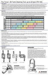
3.0 DESCRIPTIONThe Warthog 1” Rotary Sewer Nozzle was designed for waterblast cleaning of pipes and sewer lines. Jetthrust powers rotation of the head and pulls the tool thru the line. The Warthog 1” has a 1” npt threadedInlet Nut. The tool is constructed of stainless steel for corrosion resistance.The swivel is a straight flow through design with a single high pressure seal. The Warthog 1” is capable ofworking pressures up to 5000 psi and flow rates of 50 to 80 gpm, with rotation speeds from 200 to 400rpm. The unit is filled with a thick viscous fluid that controls the rotation speed.The nozzle orifice sizes should match the operating conditions of pressure and flow desired. Hose lengthand size must be known to correctly determine the proper orifice sizes. Contact <strong>StoneAge</strong> or yourdistributor to help in nozzle selection.4.0 PARTS LISTPart # Description QtyBJ 010-D Shaft Seal 2BJ 048-F Viscous Fluid, FastHC 012-TO High Pressure Seal 1MJ 011 Seat, Brass 1MJ 021-S Weep Seal 1<strong>WG</strong> 001 Shaft 1<strong>WG</strong> 002 Inlet Nut 1<strong>WG</strong> 003 Body 1<strong>WG</strong> 007 Bearing 2<strong>WG</strong> 008 O-Ring 1<strong>WG</strong> 014 Wave Spring 1<strong>WG</strong> 040-R5 Head 1<strong>WG</strong> 080 Centralizer 1Also available separately:<strong>WG</strong> 085 Super Centralizer (for use in pipes 8” ID and larger)<strong>WG</strong> 600 Service Kit (<strong>Inc</strong>ludes items needed for maintenance)<strong>WG</strong> 602 Seal Kit (<strong>Inc</strong>ludes parts needed for one seal change)<strong>WG</strong> 610 Overhaul Kit (<strong>Inc</strong>ludes parts needed for tool rebuild)<strong>WG</strong> 612 Tool Kit (<strong>Inc</strong>ludes tools to aid assembly)
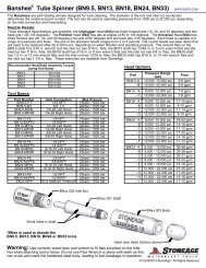
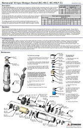
<strong>WG</strong> EXPLODED ASSEMBLY DRAWING<strong>WG</strong> 040Head<strong>WG</strong> 003BodyBJ 010-DShaft Seal<strong>WG</strong> 007Bearing<strong>WG</strong> 001Shaft<strong>WG</strong> 007Bearing<strong>WG</strong> 080Centralizer<strong>WG</strong> 014Wave SpringHC 012-TOH.P. SealMJ 011SeatBJ 010-DShaft Seal<strong>WG</strong> 008O-Ring<strong>WG</strong> 002Inlet NutMJ 021-SWeep Seal05/06
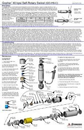
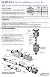
6.0 <strong>WG</strong> MAINTENANCEThe most important item in maintaining the Warthog is keepingthe tool full of viscous fluid. The tool also has a high pressureseal and seat that will need to be replaced if the tool begins toleak water from under the Weep Seal (MJ 021-S). The toolmay leak water at low pressure intermittently, but if it leaks ator near operating pressure, it is time to change the seal.To service the viscous fluid and high pressure seal:1. Unscrew the Inlet Nut (<strong>WG</strong> 002) from the Body.Hold the Body by the flats near the head.2. Check the fluid condition and level. If the fluid appearsto have water contamination or is very dirty, we recommendfurther disassembly of the tool to clean out the old fluid.Otherwise, drain out as much of the old fluid as possible andadd new viscous fluid to cover the top bearing and wave spring.3. Remove the Seat (MJ 011) and Seal (HC 012-TO) from thebore of the Shaft. Apply grease to a new High Pressure Sealand install in the bore. Install a new Seat on top of the Seal,with the flat face of the Seat facing toward the Seal, as shown.4. Apply anti-seize to the threads of the Inlet Nut and threadinto the Body. Make sure that the Seat stays centered in thebore of the Shaft. Tighten to 50 ft-lb torque.chamfered face<strong>WG</strong> 002Inlet NutMJ 011SeatHC 012-TOH.P. Sealif the high pressure seal is leaking,you will see water spraying fromunder the Weep Seal (MJ 021-S)Check fluid level(should cover bearing and wave spring)MJ 011SeatHC 012-TOH.P. Sealflat face06/02
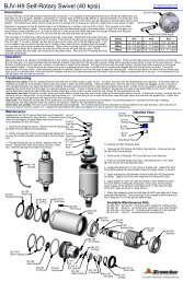
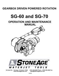
6.1 <strong>WG</strong> DISASSEMBLY INSTRUCTIONSTo disassemble the Warthog:1. Unscrew the Head (<strong>WG</strong> 040) from the Shaft.2. Unscrew the Inlet Nut (<strong>WG</strong> 002) fromthe Body (<strong>WG</strong> 003). Pull off the Centralizer(<strong>WG</strong> 080).<strong>WG</strong> 002Inlet Nut<strong>WG</strong> 080Centralizer<strong>WG</strong> 008O-RingBJ 010-DShaft Seal<strong>WG</strong> 002Inlet Nut3. Remove the O-Ring(<strong>WG</strong> 008) and Weep Seal(MJ 021-S) from the Inlet Nut.4. Remove the Shaft Seal(BJ 010-D) from the Inlet Nutif it appears damaged.5. Remove the Seat (MJ 011)and Seal (HC 012-TO) from theShaft bore.<strong>WG</strong> 007Bearing<strong>WG</strong> 001Shaftdo not dingor raise anyburrs on thisportion of ShaftMJ 021-SWeep Seal6. Remove the Wave Spring(<strong>WG</strong> 014).<strong>WG</strong> 003BodyMJ 011SeatHC 012-TOH.P. Seal<strong>WG</strong> 014Wave Spring7. Push the Shaft (<strong>WG</strong> 001)out of the Body.8. Remove the Shaft Seal(BJ 010-D) from the Bodyif it is damaged.9. Carefully pry the Bearings(<strong>WG</strong> 007) off of the Shaft.Make sure not to raise any burrson the large diameter portion ofthe Shaft with the groove.<strong>WG</strong> 007BearingBJ 010-DShaft Sealalways holdBody by flats<strong>WG</strong> 040Head06/02
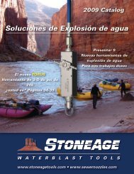
6.2 <strong>WG</strong> ASSEMBLY INSTRUCTIONS1. Install Shaft Seals (BJ 010-D) in the Body (<strong>WG</strong> 003) and the Inlet Nut (<strong>WG</strong> 002).Both seals are installed so the lip with the spring faces up when installing. Applygrease to the lips of the seals.2. Install O-Ring (<strong>WG</strong> 008) and Weep Seal (MJ 021-S) on Inlet Nut.lip of seal withspring faces upBJ 010-DShaft Seal<strong>WG</strong> 003Body<strong>WG</strong> 008O-RingBJ 010-DShaft Seal<strong>WG</strong> 002Inlet Nutlip of seal withspring faces up6. Place the Wave Spring (<strong>WG</strong> 014)on top of the Bearing. Add moreviscous fluid until the Wave Springis covered.7. Apply grease to the H.P. Seal(HC 012-TO). Insert in bore of Shaft.8. Place the Seat (MJ 011) on top ofthe Seal, with the chamfered end up.(See Section 6.0)9. Apply anti-seize to the threads ofthe Inlet Nut; thread into Body andtighten to 50 ft-lb.10. Apply teflon tape to theshaft threads and install head.<strong>WG</strong> 014Wave Springchamferedend upMJ 011SeatHC 12-TOH.P. SealMJ 021-SWeep Seal<strong>WG</strong> 007Bearing3. Press the Bearings (<strong>WG</strong> 007)onto the Shaft (<strong>WG</strong> 001).4. Place the Centralizer (<strong>WG</strong> 080)over the Body.<strong>WG</strong> 001Shaft<strong>WG</strong> 007Bearing5. If you have a Fill Tube (HC 064),insert it thru the Shaft Seal in the Bodyup to it's shoulder. Pour Viscous Fluidinto the Body about 1" deep. Insertthe Shaft into the Body, allowing theShaft to push out the Fill Tube. If youdo not have the Fill Tube, insert the Shaftinto the Body and pour viscous fluid intothe Body; allow the fluid to settle downthru the top bearing and around the Shaftand keep adding fluid until it coversthe top bearing. It will take about10 minutes to get the tool full.HC 064Fill Tube06/02
6.3 TROUBLESHOOTING GUIDESYMPTOM PROBLEM SOLUTIONLeaks around weep seal Worn H.P. seal Replace H.P. Seal (HC 012-TO)Worn seat Replace Seat (MJ 011)Damaged Inlet NutFace or replace Inlet NutSeals wear out quickly Worn seat Replace Seat (MJ 011)Worn Shaft bore Replace Shaft if bore >.635”Will not rotate Not enough jet torque Check nozzles for pluggingor wear.Internal damageRotate head by hand, if rough toturn, check bearings.Water inside tool Bad H.P. Seal leak Replace H.P. SealWorn shaft sealsReplace shaft sealsSpins too fast Low or empty viscous fluid Refill with viscous fluid.Water in viscous fluidClean and refill viscous fluid.
7.0 LIMITED WARRANTY<strong>StoneAge</strong>, <strong>Inc</strong>. warrants to the extent herein provided the products of its own manufacture against defectsin material and workmanship under normal use and service for which the products were designed for aperiod of six months after shipment from the factory. If such products should fail through defect inworkmanship or material and specific written notice of failure is made within six months after date ofshipment from factory, <strong>StoneAge</strong>, <strong>Inc</strong>. will either repair or replace any such items, F.O.B. its factory withoutcharge. <strong>StoneAge</strong>, <strong>Inc</strong>. shall not be liable for expense incurred in repairs or alterations made outside thefactory without the proper and prior authorization. <strong>StoneAge</strong>, <strong>Inc</strong>. shall have the option of requiring thereturn of the defective products to its factory, with transportation charges prepaid, to establish the claim.<strong>StoneAge</strong>, <strong>Inc</strong>. shall in no event be held liable for damages or delay resulting from or arising out ofdefective products nor for consequential damages or otherwise except for repair or replacement of itemsof defective material or workmanship aforesaid.THIS WARRANTY IS EXPRESSLY IN LIEU OF ALL OTHER WARRANTIES EXPRESSED OR IMPLIEDINCLUDING THE WARRANTIES OF MERCHANTABILITY AND FITNESS FOR USE AND NEITHERASSUMES, NOR AUTHORIZES ANY PERSON TO ASSUME FOR STONEAGE, INC. ANY OTHERLIABILITY IN CONNECTION WITH THE SALE OF ITS PRODUCTS. THIS WARRANTY SHALL NOTAPPLY TO PRODUCTS OR ANY PARTS THEREOF WHICH HAVE BEEN SUBJECT TO ACCIDENT,NEGLIGENCE, ALTERATION, ABUSE, OR MISUSE. STONEAGE, INC. MAKES NO WARRANTYWHATSOEVER IN RESPECT TO ACCESSORIES, PARTS OR PRODUCTS NOT MANUFACTURED BYSTONEAGE, INC.
APPENDIX BJ O48-F VISCOUS FLUIDOSI SPECIALTIES INC — POLYDIMETHYLSILOXANE L-405-2000MATERIAL SAFETY DATA SHEET Revision: 1.0 9/27/2000=======================================================MSDS Safety Information=======================================================MSDS Date: 9/27/2000MSDS Num: 491Product ID: L-405-2000Chemical Name: Polydimethylsiloxane(inhibited)Responsible Party: Mr. Dana DalrympleName: OSI SPECIALTIES INCAddress: ONE AMERICAN LANECity: GREENWICH CT 06831-2559Info Phone Number: 304-652-8446Emergency Phone Number: 800-809-9998; 800-424-9300(CHEMTREC)Published: Y=======================================================Ingredients=======================================================Proprietary: NOIngredient: POLYDIMETHYLSILOXANEIngredient Sequence Number: 01Percent:
Physical/Chemical Properties=======================================================Appearance:Physical state: Clear to Hazy LiquidColor: YellowOdor: MildOther Properties:Boiling Point: >250°C @STP unless specified belowMelting Point: 0.5mmHg@ 104°C / 219.2°F **Not determined**=======================================================Other Information=======================================================Chemical InventoryEurope: The ingredients of this mixture are on the EINECS inventory.United States: The ingredients of this product are listed on the TSCAinventory or are exempt.=======================================================HAZCOM Label=======================================================Product ID: POLYDIMETHYLSILOXANE L-45-2000Supplier: Crompton CorporationStreet: One American LaneCity: Greenwich, CTZipcode: 06831-2559, USAHealth Emergency Phone: 800-809-9998;800-424-9300(CHEMTREC)Label Required: YesHealth Hazard: 0Flammability: 1Reactivity: 0PPE: X=======================================================