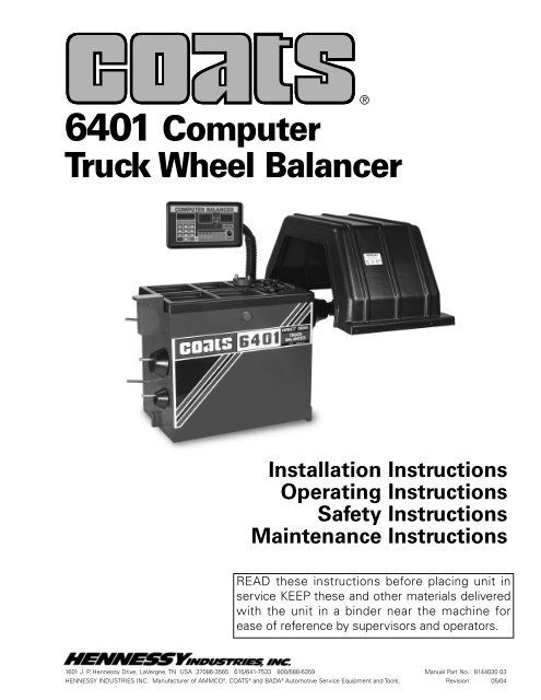
6401 Computer Truck Wheel Balancer - aesco
6401 Computer Truck Wheel Balancer - aesco
6401 Computer Truck Wheel Balancer - aesco
- No tags were found...

You also want an ePaper? Increase the reach of your titles
YUMPU automatically turns print PDFs into web optimized ePapers that Google loves.
Direct Driveii • COATS <strong>6401</strong> <strong>Truck</strong> <strong>Wheel</strong> <strong>Balancer</strong>
SafetyWARNINGRead entire manualbefore assembling,installing, operating,or servicing thisequipment.Failure to follow danger, warning, and cautioninstructions may lead to serious personal injury ordeath to operator or bystander or damage to property.Do not operate this machine until you readand understand all the dangers, warnings and cautionsin this manual. For additional copies of either,or further information, contact:Hennessy Industries, Inc.P.O. Box 3002, 1601 J.P. Hennessy DriveLaVergne, TN 37086-1982(615) 641-7533 or (800) 688-6359www.Hennessy-Ind.comImportant InformationWARNINGRubber Manufacturers Association1400 K Street N. W.Washington, DC 20005(202) 682-4800Tire Guides, Inc.The Tire Information Center1101-6 South Rogers CircleBoca Raton, FL 33487-2795(561) 997-9229www.tireguides.comOperator ProtectiveEquipmentPersonal protective equipment helps make tire servicingsafer. However, equipment does not take theplace of safe operating practices. Always wear durablework clothing during tire service activity. Loose fittingclothing should be avoided. Tight fitting leather glovesare recommended to protect operator’s hands whenhandling worn tires and wheels. Sturdy leather workshoes with steel toes and oil resistant soles should beused by tire service personnel to help prevent injury intypical shop activities. Eye protection is essential duringtire service activity. Safety glasses with sideshields, goggles, or face shields are acceptable. Backbelts provide support during lifting activities and arealso helpful in providing operator protection.Consideration should also be given to the use of hearingprotection if tire service activity is performed in anenclosed area, or if noise levels are high.Do it NowMake sure the instructionand warning decal isclean and clearly visible✓to operator.iv • COATS <strong>6401</strong> <strong>Truck</strong> <strong>Wheel</strong> <strong>Balancer</strong>
Owner’s ResponsibilityTo maintain machine and user safety, the responsibilityof the owner is to read and follow these instructions:• Follow all installation instructions.• Make sure installation conforms to all applicableLocal, State, and Federal Codes, Rules, andRegulations; such as State and Federal OSHARegulations and Electrical Codes.• Carefully check the unit for correct initial function.• Read and follow the safety instructions. Keepthem readily available for machine operators.• Make certain all operators are properly trained,know how to safely and correctly operate the unit,and are properly supervised.• Allow unit operation only with all parts in placeand operating safely.• Carefully inspect the unit on a regular basis andperform all maintenance as required.• Service and maintain the unit only with authorizedor approved replacement parts.• Keep all instructions permanently with the unitand all decals/labels/notices on the unit clean andvisible.• Do not override safety features.• If ownership of the unit is transferred, providenew owner all information, manuals, and provideCOATS new ownership information.• Warranty in non-transferable.SafetyDefinitions of HazardLevelsIdentify the hazard levels used in this manual withthe following definitions and signal words:DANGERWatch for this symbol:It Means: Immediate hazards, which will result insevere personal injury or death.WARNINGWatch for this symbol:It Means: Hazards or unsafe practices, which couldresult in severe personal injury or death.CAUTIONWatch for this symbol:DANGERWARNINGCAUTIONIt Means: Hazards or unsafe practices, which mayresult in minor personal injury or product or propertydamage.Watch for this symbol! It means BE ALERT! Yoursafety, or the safety of others, is involved!COATS <strong>6401</strong> <strong>Truck</strong> <strong>Wheel</strong> <strong>Balancer</strong> • v
SafetyIMPORTANT SAFETY INSTRUCTIONSREAD ALL INSTRUCTIONS1. Eye and face protection recommendations:“Protective eye and face equipment is required tobe used where there is a reasonable probability ofinjury that can be prevented by the use of suchequipment.” O.S.H.A. 1910.133(a) Protective goggles,safety glasses, or a face shield must be providedby the owner and worn by the operator ofthe equipment. Care should be taken to see thatall eye and face safety precautions are followed bythe operator. ALWAYS WEAR SAFETY GLASSES.Everyday glasses only have impact resistantlenses, they are not safety glasses.2. Do not disable hood safety interlock system, or inany way shortcut safety controls and operations.3. Be sure that wheels are mounted properly, thehub nut engages the arbor for not less than four(4) turns, and the hub nut is firmly tightenedbefore spinning the wheel.4. Read and understand this manual before operating.Abuse and misuse will shorten the functionallife.5. Be sure the balancer is properly connected to thepower supply and electrically grounded.6. Do not operate equipment with a damaged cordor if the equipment has been dropped or damaged– until it has been examined by a qualified serviceman.7. Do not let cord hang over edge of table, bench, orcounter or come in contact with hot manifolds ormoving fan blades.8. If an extension cord is necessary, a cord with acurrent rating equal to or more than that of theequipment should be used. Cords rated for lesscurrent than the equipment may overheat. Careshould be taken to arrange the cord so that it willnot be tripped over or pulled.9. Keep guards and safety features in place and inworking order.10. Wear proper clothing. Safety toe, non-slipfootwear and protective hair covering to containhair is recommended. Do not wear jewelry, looseclothing, neckties, or gloves when operating thebalancer.11. Keep work area clean and well lighted. Clutteredand/or dark areas invite accidents.12. Avoid dangerous environments. Do not use powertools or electrical equipment in damp or wet locations,or expose them to rain.13. Avoid unintentional starting. Be sure the balanceris turned off before servicing.14. Disconnect the balancer before servicing.15. Use only manufacturer’s recommended accessories.Improper accessories may result in personalinjury or property damage.16. Repair or replace any part that is damaged or wornand that may cause unsafe balancer operation. Donot operate damaged equipment until it has beenexamined by a qualified service technician.17. Never overload or stand on the balancer.18. Do not allow untrained persons to operatemachinery.19. To reduce the risk of fire, do not operate equipmentin the vicinity of open containers or flammableliquids (gasoline).20. Adequate ventilation should be provided whenworking on operating internal combustionengines.21. Keep hair, loose clothing, fingers, and all parts ofbody away from moving parts.22. Use equipment only as described in this manual.23. Use only manufacturer’s recommended attachments.SAVE THESE INSTRUCTIONSvi • COATS <strong>6401</strong> <strong>Truck</strong> <strong>Wheel</strong> <strong>Balancer</strong>
Direct DriveSpecifications• Cycle time . . . . . . . . . . . . . . . . .12 seconds (avg.)• Max Tire Diameter . . . . . . . . . . . . . . . . .46 inches• Max Tire Weight . . . . . . . . . . . . . . . . .200 pounds• Rim Diameter . . . . . . . . . . . . . . . . . . . .16 inches• <strong>Wheel</strong> Width Range . . . . . . . . . .4.5 to 25 inches• Balancing Increments:<strong>Truck</strong> <strong>Truck</strong> RV CarRound Off Dynamic Static Dynamic DynamicOunce 2.0 2.0 wt≤4.0; .5 .25wt>4.0; 1.0 .5Grams 50 50 wt≤100; 10 wt>55; 10wt>100; 20 wt≤55; 5• Resolution (Round Off Mode) . . .0.01 ounce, 1.4º• Motor - Modified torque with 850 RPM rating,forced air cooling, large housing for heat dissipation,and heavy duty insulation for high temperatureapplications• <strong>Balancer</strong> Weight . . . . . . . . . . . . . . . . .900 pounds• Shipping Weight . . . . . . . . . . . . . . .1,100 poundsStandard Accessories• 5/16 Allen Wrench• Weight Hammer• <strong>6401</strong> Threaded Stud• Accessory Pegs• Hood Springs• Caliper• Small Cone• Medium Cone• Large Cone• <strong>Truck</strong> Cone• <strong>Truck</strong> Cone Spacer• Back Cone Spring• Pressure Drum• Hubnut Wrench, Large• Hubnut Wrench, Small• HubnutOptional Accessories• Tire/<strong>Wheel</strong> Lift #0501: A roll-around hydraulic liftfor mounting tire and wheel assembly to the balancer• Dayton <strong>Wheel</strong> Adapter for 20-22.5 Inches• Dayton <strong>Wheel</strong> Adapter for 22-24.5 Inches• Combi Adapter for Most <strong>Truck</strong> <strong>Wheel</strong>s• HubFeatures• Exclusive Direct Drive System - No Belts orPulleys• Will Balance Most Automotive, All <strong>Truck</strong>, RV andLight <strong>Truck</strong> <strong>Wheel</strong>s• Backcone And <strong>Truck</strong> Cone Mounting Systems• Single Spin Dynamic Two Plane Balance Or StaticBalance• Vertical <strong>Wheel</strong> Mounting• Hood Safety Interlock System• Static, Car/RV And <strong>Truck</strong> Operating Modes• Adjustable Control Panel- Scratch and Solvent Resistant- Large, Bright Digital Displays- Easy-to-Read Position Indicators- Large Keypad for Data Entry- Easily Repositioned for Best Visibility- Electronics Isolated from Motor Heat- Automatic Memory and Program Check• Automatic Rim Gauge Return• Simple Calibration• Removable Shaft Stud• Oversized Weight Bins• Built In Anvil for Hammering Weights• "No Bolt-Down" Installation2 • COATS <strong>6401</strong> <strong>Truck</strong> <strong>Wheel</strong> <strong>Balancer</strong>
Direct DriveInstallation and SetupA factory trained COATS ® Service Technician must perform theinstall, setup, and initial test procedures on your <strong>6401</strong> balancer.Do not attempt to install and setup the unit yourself. Accurateand reliable operation of your unit depends on proper installation.Please contact COATS ® directly at 1-800-688-9240 for theCertified Service Partner nearest you.Floor and Space RequirementsThe balancer must be located on a flat floor of solid construction,preferably concrete. The balancer must sit solidly on itsthree feet. If the balancer is not level, does not sit solidly on itsthree feet, or is placed on an unstable floor, the balancer will notfunction properly and will produce inaccurate balance readings.Do not operate the balancer when it is still bolted down orwhile it is on the pallet.Select a location for the balancer that provides a level, solidfloor, and adequate clearance around and above the balancer(Figure 1). Make sure the location selected has enough roomabove and behind the unit so the hood can be raised completely.The location must also provide working room for mounting andremoving wheels.Figure 1 - Space RequirementsCOATS <strong>6401</strong> <strong>Truck</strong> <strong>Wheel</strong> <strong>Balancer</strong> • 3
Direct DriveUnpack and Setup the Unit1. Install the two (2) hood springs.2. Mount hood using the three (3) hex bolts (3/8-16 UNC x 1"),matching hex nuts and lock washers supplied in the accessorybox.3. Remove the bolts holding the balancer to the pallet. With aforklift, carefully lift the balancer off the pallet and move to finalposition.CAUTIONDo not use the control pod, control pod arm, faceplate,hood or stub shaft to lift the balancer.4. Install and tighten the four (4) accessory pegs and hang theaccessories.5. Install and tighten the threaded stud into end of motorshaft.6. Loosen the four 5/16" nuts and raise the control pod supportarm. Raise it high enough to allow room for the pod torotate into position and for the Match Mount instructions tolower below the pod.Adjustment KnobsFigure 2 - Control Pod Adjustment Knobs7. Lightly tighten the control pod support arm retainer nuts onthe side of the support bracket. Arm will be adjusted and tightenedlater.8. Loosen the two adjustment knobs on the back of the controlpod (Figure 2).9. Rotate the pod into operating position, and retighten theknobs.10. Loosen the nuts on the support arm retainers. Raise orlower the control pod into the desired position, and tighten theretainer nuts securely. The bottom edge of the pod should be atleast 8 inches above the top of the balancer (Figure 3).8" Min.11. Lower the Match Mount instructions attached to theunderside of the control pod. If there is not enough roombetween the pod and the balancer weight tray to fully lower theinstruction card, the pod should be raised.Figure 3 - Control Pod Height12. Position the balancer in its final operating location. Lightlytighten the four 5/16" nuts4 • COATS <strong>6401</strong> <strong>Truck</strong> <strong>Wheel</strong> <strong>Balancer</strong>
Direct DriveConnect to PowerYour factory trained COATS ® Service Technician should do thefinal check to verify the power installation before connecting thebalancer to a power supply. Failure due to improper power connectionwill void the warranty.Connect the balancer to an appropriate electrical receptacle.Refer to Figures 4 and 5, as well as Electrical Requirements onpage 1.Note: If pedestrian or equipment traffic might damage thestandard power cord, power outlets must be enclosed in a racewayon the floor or in an overhead drop.Note: Electric outlets must be solidly connected. There shouldbe less than 1 Ω electrical resistance between the ground pinand earth ground. The installer or electrical inspector must verifythe outlet installation before connecting the balancer. Failuredue to improper power connection will void the warranty.Note: The green wire in the cord is the grounding wire. Neverconnect the green wire to a live terminal.Initial TestingThis should be performed by your factory trained COATS ®Service Technician.Precautions: Initial testing should be performed by theinstructor. Power requirements must be verified by the installeror instructor before connecting balancer. Failure to observe thisprecaution may void warranty.Power: Plug power cable into power outlet receptacle. Set circuitbreaker in building breaker panel on. Set On/Off switch on.Leave power on during an entire work day.Cooling Air: Check to verify cooling air blower is running. Donot operate unit unless cooling air flow is present.*Spin: (220 VAC 3 phase units) Press START button with hooddown. Faceplate should rotate clockwise. If initial direction offaceplate rotation is incorrect, an error message will show in thecontrol panel display: ERROR. Set On/Off switch off. Set buildingcircuit breaker off. Interchange X and Y wires in outlet plug.Set building circuit breaker on. Set On/Off switch on. PressTRUCK button. Faceplate initial rotation should be clockwise.*Spin: (220 VAC single phase units) Press START button withhood down. Faceplate should rotate clockwise for an intervaland then stop.Note: If the above conditions cannot be obtained during initialtest, call the distributor for service advice.Three-PhaseFigure 4 - Three-Phase Wiring DiagramSingle-PhaseHotFigure 5 - Single-Phase Wiring DiagramGroundHot195-230 VBetweenHot WiresHotGreen/GroundA – RedB – Black*Mount a tire/wheel assembly to avoid HUB ERR.COATS <strong>6401</strong> <strong>Truck</strong> <strong>Wheel</strong> <strong>Balancer</strong> • 5
Direct DriveOperating Overview21213 13123 4 5617810 119TRUCKDYNAMICTRUCKSTATICRVDYNCARDYNControl Panel1 Keypad - User enters information and selectsfunction using these keys.2 <strong>Wheel</strong> Measurement Display - Displays A, W,and D values.3 <strong>Wheel</strong> Offset (A) - The distance between theinner rim flange and the edge of the balancer. Refer toOffset on page 9 for detailed instructions.4 <strong>Wheel</strong> Width (W) - The width of the rim betweenthe inner and outer rim flanges. Refer to Width onpage 10 for detailed instructions.5 <strong>Wheel</strong> Diameter (D) - The diameter of the wheelat the weight location. Refer to Diameter on page 10for detailed instructions.6 Calibrate - Places the balancer in the CalibrateMode. Press and hold the SHIFT key, and press 1.7 Round Off - Toggles the balancer between thehigh accuracy mode (0.01-ounce increments) and thenormal mode (0.25-ounce increments). Press and holdthe SHIFT key, and press 6.8 Ounce/Gram - Toggles the balancer betweenounces or grams. Press and hold the SHIFT key, andpress 9.9 Mode - Selects the desired balancing mode.10 Balancing Modes - Press the MODE key toselect from the 4 available modes. The LED above themode will illuminate to indicate the mode is selected.11 Start Button - Press to start a spin cycle.12 Weight Displays - Indicate the weight amount tobe attached to the wheel.13 Weight Position LEDs - Center LEDs flash whencorrect weight position is at top-dead-center.6 • COATS <strong>6401</strong> <strong>Truck</strong> <strong>Wheel</strong> <strong>Balancer</strong>
Selecting Balancing ModeFour balancing modes are available on the <strong>6401</strong>. Select the balancingmode based on wheel type and customer request. Pressthe mode key to select the desired balance type. The LED willilluminate to indicate your selection. In the static mode, the balancerwill automatically adjust the wheel diameter to compensatefor the actual location of the weight(s).Note: See page 12 for balancing procedures.Car DynamicRV DynamicDirect DriveThe most common mode used for passengercars and light trucks (Less than 14" diametertires). Selecting this mode tells the balancerthat standard clip weights will be used on theinner and outer rim flanges.Use this mode to balance larger wheels that donot require balancing at 0.5 ounce or below (14"to 16" diameter tires).<strong>Truck</strong> DynamicUse this mode to balance larger wheels that donot require balancing below 2 ounces (16"+diameter tires).<strong>Truck</strong> StaticUse this mode to static balance large wheels(16"+ diameter tires). This is a two-plane staticbalance.Selecting Balancing OptionsRound Off - The default weight measurement on the balanceris 0.25 ounces in car mode or 0.50 ounces in truck mode. Thebalancer can be set to a non-Round Off mode that displaysweights in 0.01 ounce increments. Press and hold the SHIFTkey and press 6 to toggle between the Round Off and non-Round Off modes.Ounce/Gram - In the default mode, the balancer will operatein ounces. The balancer can be set to operate in grams by pressingand holding the SHIFT key and pressing 9. Toggle back toounces by using the same key sequenceCOATS <strong>6401</strong> <strong>Truck</strong> <strong>Wheel</strong> <strong>Balancer</strong> • 7
Direct DriveReading the DisplaysWeight Displays - The two weight displays (one for the innerplane, and one for the outer plane) are positioned with a wheelcross section diagram. After spinning the wheel, the balancerwill calculate the weight needed and display it in these displays.The display to the left of the diagram will show the weight to beapplied to the inner plane of the wheel and the display to theright will show the weight for the outer plane.Error messages and system messages will also be shown inthese displays.Weight Position LEDs - Each weight display includes weightposition LEDs. Located between the weight display and thediagram, these LEDs indicate the proper location for weightapplication. After a spin, rotate the wheel until the centerposition indicator LEDs flash. This indicates that the positionspecified by the balancer for weight application is at top-deadcenter.Display Messages - Both inner and outer displays will show0.00 when the balancer is first turned on or after clearing thememory. The balancer may also display the followingmessages:Err - An error was detected after the start button waspressed. The error is in one of the wheel measurementsentered into the balancer. Check your measurements and reenteras needed.Err 3 - Circuit malfunction. Call the Hennessy ServiceDepartment at (800) 688-6359.Hood (hod) - The hood has been raised during the balancingcycle. The balancer will automatically brake to a stop. Thehood must be down with the safety interlock engaged for thebalancer to spin.Hub - The hub nut has come loose. The balancer will automaticallybrake to a stop when the wheel is 13 inches orlarger in diameter. Retighten the hub nut and respin.8 • COATS <strong>6401</strong> <strong>Truck</strong> <strong>Wheel</strong> <strong>Balancer</strong>
Direct DriveBalancing ProceduresMount <strong>Wheel</strong>Choose the correct mounting method:1. Back Cone Mounting: Use only small or medium cones(See page 13).2. Front Cone Mounting: Any cone can be used (See page 13).3. Combi Adapter: Where center cone mounting cannot beused due to an oversized center hole of rim (See pages 14).Adapts to: 275 mm (10.827") Bolt circle, 8 hole rims.11 1/4" Bolt circle, 10 hole rims.335 mm (13.188") Bolt circle, 10 hole rims.4. Dayton Adapters 20" & 22.5", 22" & 24.5": For use with truckspoke wheels only (See page 15).Offset1. Press the offset key.Move distance gauge totouch edge of wheel.2. Read this distancemeasurementon the arm.PRESS3. Enter offsetdistance using thekeypad.COATS <strong>6401</strong> <strong>Truck</strong> <strong>Wheel</strong> <strong>Balancer</strong> • 9
Direct Drive2. Read thewidth readingon the calipers.WidthPRESS1. Press the width key. UseRim Width Calipers to measurewheel at points shown.3. Enter wheelwidth informationusing the keypad.Diameter1. Press the diameter key.Read rim diameter size asread from tire sidewall.PRESS2. Enter diameterusing the keypad.10 • COATS <strong>6401</strong> <strong>Truck</strong> <strong>Wheel</strong> <strong>Balancer</strong>
Direct DriveTake Readings1. Weight and position readings will appear on displays asbalancer is braking tire.Attach Weight1. Rotate wheel until right (outer) red position lights begin toflash.2. Attach a weight equal to outer weight reading at topdead center of outer rim (see #2).3. Rotate wheel until left (inner) red position lights begin toflash.4. Attach a weight equal to inner weight reading at top deadcenter of inner rim (see #4).5. Respin wheel after weights are applied to obtain 0.00reading.0:000:00Note: The more accurate you are in selectingthe exact weight and position, the more oftenyou will balance in one spin.COATS <strong>6401</strong> <strong>Truck</strong> <strong>Wheel</strong> <strong>Balancer</strong> • 11
Direct DriveBalancing <strong>Wheel</strong>s<strong>Truck</strong> Dynamic1. Select <strong>Truck</strong> Dynamic mode using the keypad.2. Set distance gauge, wheel width and wheel diameteras indicated in BALANCING PROCEDURES.3. Lower hood and push START.4. Raise hood and attach weight as indicated in BAL-ANCING PROCEDURES.5. Lower hood. Respin wheel to obtain 0.00 reading.<strong>Truck</strong> StaticNote: This method is equivalent to a bubble balance.1. Select <strong>Truck</strong> Static mode using the keypad.2. Set distance gauge, wheel width and wheel diameteras indicated in BALANCING PROCEDURES.3. Lower hood and push START.4. Raise hood and attach weight as indicated in BAL-ANCING PROCEDURES.Note: Use two standard clip weights to split theweight on the inner and outer rim.Note: One weight, using the total imbalance amount,may be used on the inside.Note: If one tape weight is desired on the drop centerthen set the rim diameter “D” 1 1/2" smaller thantire size.5. Lower hood. Respin wheel to obtain 0.00 reading.RV Dynamic1. Select RV Dynamic mode using the keypad.2. Set distance gauge, wheel width and wheel diameteras indicated in BALANCING PROCEDURES.3. Lower hood and push START.4. Raise hood and attach weight as indicated in BAL-ANCING PROCEDURES.5. Lower hood. Respin wheel to obtain 0.00 reading.Car Dynamic1. Select Car Dynamic mode using the keypad.2. Set distance gauge, wheel width and wheel diameteras indicated in BALANCING PROCEDURES.3. Lower hood and push START.4. Raise hood and attach weight as indicated in BAL-ANCING PROCEDURES.5. Lower hood. Respin wheel to obtain 0.00 reading.STARTStandard clipweight will beattached here.Standard clipweight will beattached here.12 • COATS <strong>6401</strong> <strong>Truck</strong> <strong>Wheel</strong> <strong>Balancer</strong>
Direct Drive<strong>Wheel</strong> Mounting OptionsCAUTIONHubnut must engage threads for at least four full turns.Failure to tighten hubnut securely or to force wheelfirmly against the faceplate may result in serious personalinjury.Back Cone MountingUse only small or medium cones.1. Place spring over threaded stud with the large end insideof the faceplate. Spring must be used.2. Select a cone that best fits into wheel center hole.Use only small or medium cones. If a larger cone isrequired, use the front cone mounting system.3. Slide selected cone onto threaded shaft with the largeend against the spring.4. Lift wheel onto shaft and center on cone.5. Slide pressure drum onto threaded shaft with the large endagainst the wheel.6. Thread hubnut on and tighten with hubnut wrench. If hubnutwon't tighten all the way down, use the front cone mounting system.The wheel must be forced firmly against the faceplate.7. If you still can't tighten hubnut because of a lack of threads, usean additional cone to act as a spacer between the hubnut and pressuredrum.Front Cone MountingCan be used with all cones (do not use spring). This method workswell with most truck wheels where the bolt circle is less than 275mm.1. Select a cone that best fits into wheel center hole.2. Lift wheel onto threaded shaft.3. Slide selected cone onto shaft with the small end againstthe wheel.4. By lifting wheel from bottom, center on cone.5. Thread hubnut on and tighten with hubnut wrench. If hubnutwon't tighten all the way down, remove cone and wheel. Slide truckcone spacer over faceplate and repeat steps 2 thru 5. The wheelmust be forced firmly against the faceplate.6. If you still can't tighten hubnut because of a lack of threads,use an additional cone to act as a spacer between the hubnut andexisting cone.COATS <strong>6401</strong> <strong>Truck</strong> <strong>Wheel</strong> <strong>Balancer</strong> • 13
Direct DriveCombi Adapter (Optional)1. Determine the correct hole pattern by comparing the rim tothe adapter. <strong>Wheel</strong>s with the largest bolt circle (335 mm) shouldbe fastened to the large diameter side of the reversible adapterallothers should be fastened to the small diameter side (seeillustration below).2. Fasten threaded studs from back of adapter using the 5/16Allen wrench. Leave enough threads to securely fasten hex nutsand lock washers.3. Slide lock washers on. Hold the studs in place with the 5/16Allen wrench while threading the hex nuts on, then tightenthem down with a 5/16 wrench.4. Mount the adapter onto the faceplate by inserting the two(2) drive pins of the adapter into the matching holes in the faceplate.5. Slide truck cone onto shaft with the small end inside thecenter hole of the adapter. Mount by front cone method only.6. Thread hubnut on and tighten with hubnut wrench. Theadapter must be forced firmly against the faceplate.7. Mount the wheel onto the adapter's lugs. Fasten wing nutsby hand then securely tighten them with a rubber mallet. <strong>Wheel</strong>must be forced firmly against the faceplate.CAUTIONWing nuts must engage threads for at least six fullturns. Hubnut and cone must force wheel andadapter firmly against the faceplate. Failure totighten hubnut or wingnuts securely may result inserious personal injury.14 • COATS <strong>6401</strong> <strong>Truck</strong> <strong>Wheel</strong> <strong>Balancer</strong>
Direct DriveDayton AdaptersDayton <strong>Wheel</strong> Adapter (110785) - This adapter fits duplex rims(18 x 22.5 tires) for steering axles, and standard rims from 20"to 22.5".The adapter mounts on a Dayton rim from the front side. On arim used in a dual wheel application, mount the adapter wherethe spacer would have been placed. For a rim used on a steeringaxle application, mount the adapter where the wheel clampswould have been placed.Space variation between edgeof outer flange wall and edgeof marker not to exceed 3/32".1. Fully retract the adapter centering rods by turning theeccentric to the left (counterclockwise).2. Loosen the clamps and turn them to a position parallel withthe edge of the adapter.3. Set the adapter into the front side of the rim. Center thevalve stem between clamps.Do not gageto edge offlange.4. Center the adapter in the rim by turning the eccentric.Insert the spanner wrench into the slot in the eccentric and turnit to the right (clockwise).5. Reach through from the front of the rim and turn theclamps until they are 180º in relation to the clamping surface onthe backside of the rim.6. Tighten the clamps finger tight from the front side of theadapter. When clamps are finger tight use a 3/4" open end orbox wrench to tighten all the clamps securely. A 1/2 to 3/4 turnis usually sufficient. Do not use an air wrench.The wheel is now ready to be mounted on the balancer. Usethe appropriate cone to fit the center hole. Remove the adapterby reversing the installation instructions.Accessory Kit (110786) - Contains additional parts to modifythe 110785 adapter to fit 22" and 24.5" rims.1. Remove the wear plates from the three arms.2. Remove the clamps from the arms.3. Install the three arm extensions and rod extensions.4. Install the longer clamps.The adapter will now fit 22" and 24.5" demountable wheels.Install the adapter according to the steps provided for 20" and22.5" rims.CAUTIONHubnut and cone must force adapter firmly againstthe faceplate. Failure to tighten hubnut or rim clampnuts securely may result in serious personal injury.COATS <strong>6401</strong> <strong>Truck</strong> <strong>Wheel</strong> <strong>Balancer</strong> • 15
Direct DriveSpecial ProblemsCustomers will occasionally complain of vibration on the carafter balancing. Some possible causes are listed below:1. Beads improperly seated. Check bead seating and inflationpressure before balancing spin.2. Stiffness variations in radial belts.3. Tire out of round; wheel out of round, bent, or not runningtrue. Visually check runout of wheel and tire during balance spin.Re-check mounting. Replace wheel or tire if necessary.4. Suspension wear, misalignment, or loose vehicle components.5. <strong>Wheel</strong>s not correctly centered due to damaged hub, damagedor worn center hole, worn bolt circle holes, or impreciseoriginal design. Check wheel run out before balance spin and onthe vehicle after mounting.6. Sensitive suspensions. Set the balancer to a non-Round Offmode (See page 6).Complaint: <strong>Balancer</strong> uses too many weights or several spinsto balance.Remedy: Recheck rim dimensions entered. Position theweights exactly top dead center when red position lights are on.Complaint: Weight or position readings fluctuate.Remedy: Check cone/hubnut for slippage. Check the balanceris resting firmly on three mounting points, floor is flat and stable,and that no tools or weights are between balancer and floor.16 • COATS <strong>6401</strong> <strong>Truck</strong> <strong>Wheel</strong> <strong>Balancer</strong>
Direct DriveMaintenance andCalibrationPreventative MaintenanceThe balancer requires only minor maintenance tokeep the unit operating properly.CAUTIONNEVER use compressed air or a water hoseto clean any part of your balancer.Note: It is critical that this weight be placed accuratelyto achieve proper calibration.7. Lower the hood and press START.8. Raise the hood and remove the weight.The balancer is now calibrated. If a mistake is madeduring this procedure, turn the balancer off, then backon, and start the procedure over again.1. Keep the display clean and clear. Use a vaporizingcleaner only. Do not use cleaners or solvents, whichleave oily or filmy residues behind.2. Keep the adapters, cones, faceplate, threadedarbor, pressure cup, and hub nut clean. Grease anddirt buildup will cause premature wear and inaccuratebalancing. Clean at least once a day with a vaporizingsolvent.3. Clean the weight tray, accessory post, and pegs.Weights stored in a dirty tray will pick up grease anddirt which may alter their weight or keep them fromsecurely attaching to the wheel. Use a vaporizing solventto clean the tray, pegs, and post.4. Keep the area around the balancer clear. Removeany tools or other items that are leaning against thebalancer. Keep the area under the balancer clear aswell. Remove any items that may cause the balancerto not sit level.5. Use only COATS accessories. Accessories fromother manufactures may not fit or function properly,and may damage the balancer.CalibrationThe balancer utilizes a “self calibration” scheme. Tokeep your balancer in proper calibration, this calibrationprocedure should be performed once a month, orwhenever the accuracy of the balancer is questioned.1. Mount a 16 or 16.5 light truck tire/wheel assemblyon the balancer.2. Enter A, W, and D wheel measurements.Note: Make sure the balancer is in NON ROUNDOFFmode (SHIFT 6).3. Remove any weights attached to the wheel. Thebalancer will read CAL 0.4. Press and hold SHIFT and press 1.5. Lower the hood and press START.6. Raise the hood, rotate the wheel until the outerweight positioning LED flashes, and attach an 8 ounceweight (227 grams) at top-dead-center.COATS <strong>6401</strong> <strong>Truck</strong> <strong>Wheel</strong> <strong>Balancer</strong> • 17
8144030 03 06/04 © Copyright 2000 Hennessy Industries and COATS All Rights Reserved Printed in USA