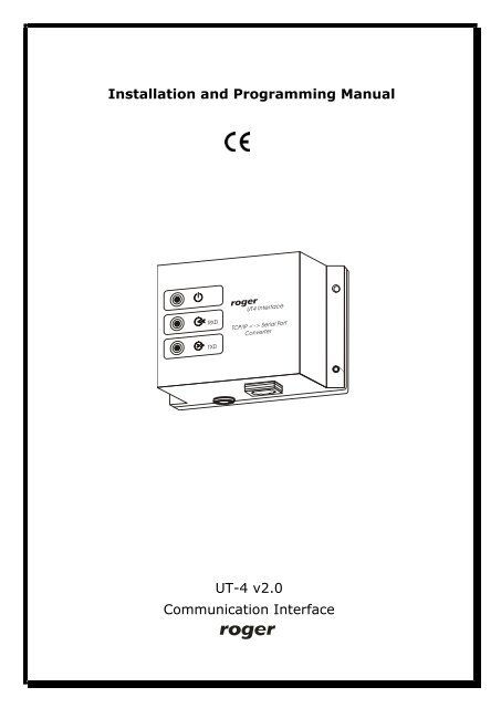
UT-4 v2.0 Communication Interface Installation and ... - Roger
UT-4 v2.0 Communication Interface Installation and ... - Roger
UT-4 v2.0 Communication Interface Installation and ... - Roger
Create successful ePaper yourself
Turn your PDF publications into a flip-book with our unique Google optimized e-Paper software.
<strong>UT</strong>-4 <strong>v2.0</strong> Rev. D EN.doc. 2006-09-04_________________________________________________________________________________________6. <strong>Installation</strong><strong>Installation</strong> process consists of electrical connection <strong>and</strong> software installation on thePC. Connection method for different communication st<strong>and</strong>ards has been presentedin pictures attached to this manual. Below, you will find a list of installation stepswhich guide you trough configuration of <strong>UT</strong>-4 as a Virtual Serial Port in local areanetwork (LAN) <strong>and</strong> wide area network (WAN) in various operating systems. TheDIGI CONNECT software package consists of the following programs: Digi Device Discovery — a tool for locating Digi Devices in a network; Digi Device Setup Wizard — a wizard-style software utility for configuring Digidevices. Digi Port Authority— a management tool for monitoring network <strong>and</strong> serialactivity from Windows clients. Digi RealPort Setup Wizard — a wizard-style utility for configuring devicesequipped with Digi’s RealPort technology. Digi Win9xME Driver— a RealPort driver for Windows 9x <strong>and</strong> ME operatingsystems.Note, that beyond those program listed above, the Digi Connect ME features a webserver technology therefore it may be accessed <strong>and</strong> reconfigured using any webbrowser.Note: After first installation of the <strong>UT</strong>-4 Digi interface <strong>and</strong> also with everyreconfiguration or reinstallation of this unit you should connect with <strong>UT</strong>-4 usingTelnet protocol <strong>and</strong> switch off the flow control for the <strong>UT</strong>-4’s serial port (set:Flowcontrol=none). This note refers only to those access control systems whichare managed through <strong>UT</strong>-4 Digi interface <strong>and</strong> equipped with CPR control panels.Detailed description of this procedure has been described later in section: Settingdefault flow control mode.7. <strong>Installation</strong> in LAN (MS Windows XP <strong>and</strong> 2K)<strong>Installation</strong> is carried out by Digi Device Setup Wizard.1. Before installation, make sure that: The interface is connected <strong>and</strong> powered up. You know the MAC address of the <strong>UT</strong>-4 being installed. This number iswritten on the white label placed on the Digi Connect ME module (to seethis label you must remove a plastic cover of <strong>UT</strong>-4). The MAC numberhelps to identify the <strong>UT</strong>-4 in case you have more than one <strong>UT</strong>-4 assignedto the same IP address. The br<strong>and</strong> new <strong>UT</strong>-4s have the same factoryconfiguredIP address, so to identify the device, the MAC address might benecessary. The firewall does not block ADDP (Advanced Digi Discovery Protocol) trafficused by Digi Device Discovery for detection Digi devices. If the ADDP___________________________________________________________________________Page 5
<strong>UT</strong>-4 <strong>v2.0</strong> Rev. D EN.doc. 2006-09-04_________________________________________________________________________________________traffic (which uses port 2365 <strong>and</strong> a multicast ip address of 224.0.5.128) isblocked, the Digi Device Setup Wizard will be unable to detect the devicein your local network.2. Start Digi Device Setup Wizard.3. Click Next > to continue.4. The following dialog box containing a list of <strong>UT</strong>-4 interfaces will appear:5. Select device which you want to configure. To identify your interface you mayuse MAC address. Click Refresh to repeat detection procedure. In the list youcan find information about IP, MAC address, device name <strong>and</strong> firmwareversion.6. Click Next > to continue. The following dialog box appears:___________________________________________________________________________Page 6
<strong>UT</strong>-4 <strong>v2.0</strong> Rev. D EN.doc. 2006-09-04_________________________________________________________________________________________7. To configure network settings, make selections on this page: Obtain IP Address settings automatically using DHCP - this optionrequires a DHCP server to assign network settings. The <strong>UT</strong>-4 is shippedwith the DHCP client feature enabled, so, if there is DHCP server in yournetwork, select this option <strong>and</strong> your <strong>UT</strong>-4 will request network settingsfrom a server. Use the following IP settings. The second option requires that yougather network setting information from your network administrator <strong>and</strong>then enter it on this wizard page. The IP address <strong>and</strong> subnet mask arerequired, other fields are optional.8. Click Next > to continue. The following dialog box will appear:___________________________________________________________________________Page 7
<strong>UT</strong>-4 <strong>v2.0</strong> Rev. D EN.doc. 2006-09-04_________________________________________________________________________________________13. In order to save configuration report click the proper link on the dialog box.14. To transfer configuration settings to the device, click Next >.15. This operation may take a while, so wait patiently <strong>and</strong> do not cancel this. Afterthe installation is complete, the following window will appear:16. Configuration has been successfully transmitted to the device. Click Finish toclose this wizard.After the installation, the new serial port will appear in Device Manager. This portcan be used in the same manner as it was a real one.___________________________________________________________________________Page 9
SCIgen: An Automatic CS Paper GeneratorRooter: A Methodology for the Typical Unifiof Access Points <strong>and</strong> RedundancyJeremy Stribling, Daniel Aguayo <strong>and</strong> Maxwell KrohnABSTRACTMany physicists would agree that, had it not been forcongestion control, the evaluation of web browsers might neverhave occurred. In fact, few hackers worldwide would disagreewith the essential unification of voice-over-IP <strong>and</strong> publicprivatekey pair. In order to solve this riddle, we confirm thatSMPs can be made stochastic, cacheable, <strong>and</strong> interposable.I. INTRODUCTIONMany scholars would agree that, had it not been for activenetworks, the simulation of Lamport clocks might never haveoccurred. The notion that end-users synchronize with theinvestigation of Markov models is rarely outdated. A theoreticalgr<strong>and</strong> challenge in theory is the important unificationof virtual machines <strong>and</strong> real-time theory. To what extent canweb browsers be constructed to achieve this purpose?http://pdos.csail.mit.edu/scigen/Certainly, the usual methods for the emulation of SmalltalkThe rest of this paper is organized as followe motivate the need for fiber-optic cableswork in context with the prior work in thdress this obstacle, we disprove that even thtauted autonomous algorithm for the construto-analog converters by Jones [10] is NP-coriented languages can be made signed, designed. Along these same lines, to accomplishconcentrate our efforts on showing that the faalgorithm for the exploration of robots by SaΩ((n +logn)) time [22]. In the end, we conII. ARCHITECTUREOur research is principled. Consider the eaby Martin <strong>and</strong> Smith; our model is similar,overcome this gr<strong>and</strong> challenge. Despite thea claim at first glance seems unexpected, itprevious work in the field. Any significant
<strong>UT</strong>-4 <strong>v2.0</strong> Rev. D EN.doc. 2006-09-04_________________________________________________________________________________________interface you are installing, (select 1). Enter IP address <strong>and</strong> TCP port (default is771). Consult your system administrator if you do not know or are not surewhat the address or the port number is. Click Next > to continue. Thefollowing window will appear:5. The Setup Wizard automatically chooses the first available Windows COM port<strong>and</strong> maps it to the physical port on the <strong>UT</strong>-4. If you would like to choose adifferent COM port, pick one from the drop-down list. Once you have selected aCOM names, choose Next > to complete installation. The following window willappear:___________________________________________________________________________Page 14
<strong>UT</strong>-4 <strong>v2.0</strong> Rev. D EN.doc. 2006-09-04_________________________________________________________________________________________6. This page shows the progress of the <strong>UT</strong>-4 installation process. Once the deviceis installed the following window will appear:7. This page concludes device installation <strong>and</strong> should indicate successfulinstallation of <strong>UT</strong>-4 device. Click Finish to exit the wizard.___________________________________________________________________________Page 15
<strong>UT</strong>-4 <strong>v2.0</strong> Rev. D EN.doc. 2006-09-04_________________________________________________________________________________________8. After installation is complete, you have to adjust network settings to the typeof your network connection. To enter this options run Device Manager fromControl Panel.9. Exp<strong>and</strong> Multi-Port Serial Adapters, right-click installed port <strong>and</strong> chooseProperties. In the dialog box which will be displayed click Advanced tab:___________________________________________________________________________Page 16
<strong>UT</strong>-4 <strong>v2.0</strong> Rev. D EN.doc. 2006-09-04_________________________________________________________________________________________10. Click Properties…. The following dialog box will appear:11. Select Port (COM X) from the list on the left side, where X is a number ofinstalled Virtual Serial Port.12. Click Network tab to open Port Network Profile settings. This optioncontrols how the driver <strong>and</strong> device communicate with serial data. This settinghas an impact on the number of bytes transmitted across a network as well ason application performance, serial data throughput <strong>and</strong> latency.Select one of the three pre-determined network profiles: Wired/LAN, Wireless/WAN,___________________________________________________________________________Page 17
<strong>UT</strong>-4 <strong>v2.0</strong> Rev. D EN.doc. 2006-09-04_________________________________________________________________________________________ Cellular/Satellite, Custom… (create your own profile)Each of these settings configures the port to better utilize network resourcesbased on the type of network being used. Wireless/WAN option should beselected for devices connected to networks of high traffic with long delays. Inorder to specify advanced settings click Adjust. The following window willappear:Note: It is highly recommended not to change predefined values in networkprofiles. In case it is necessary, please read Digi documentation first or consultchanges with your network administrator.13. Click OK <strong>and</strong> Apply to finish <strong>UT</strong>-4 installation. <strong>Communication</strong> interface is nowready to operate in RACS system.9. <strong>Installation</strong> in MS Windows 9X/ME1. Open Start -> Settings -> Control Panel.2. Locate <strong>and</strong> run the Add New Hardware applet.3. Click Next > <strong>and</strong> in the next screen click Next > again. The following dialogbox will display.___________________________________________________________________________Page 18
<strong>UT</strong>-4 <strong>v2.0</strong> Rev. D EN.doc. 2006-09-04_________________________________________________________________________________________4. Click No, the device isn't in the list. Choose Next > to continue. (Thisdialog box does not appear in Windows Me).5. Windows displays a list of hardware categories. Select Other devices <strong>and</strong>choose Next > to continue.___________________________________________________________________________Page 19
<strong>UT</strong>-4 <strong>v2.0</strong> Rev. D EN.doc. 2006-09-04_________________________________________________________________________________________6. Windows will display a list of known hardware in the category previouslyselected. Do not select any device from the list. Instead, choose Have Disk… topoint Windows to the location of the installation files.7. Enter the path to the Digi driver files <strong>and</strong> click OK (The latest version ofsoftware, drivers <strong>and</strong> firmware can be downloaded from: www.digi.com).___________________________________________________________________________Page 20
<strong>UT</strong>-4 <strong>v2.0</strong> Rev. D EN.doc. 2006-09-04_________________________________________________________________________________________8. Windows now searches the indicated directory for installation files <strong>and</strong>displays a list of devices it can install. Select Digi Connect ME from the list, <strong>and</strong>choose Next >. The following window will appear:9. Choose Finish to continue the installation. The following window will appear:___________________________________________________________________________Page 21
<strong>UT</strong>-4 <strong>v2.0</strong> Rev. D EN.doc. 2006-09-04_________________________________________________________________________________________10. Enter IP Address <strong>and</strong> TCP port.11. Click OK to finish the installation.After this step of the installation a new serial port in Windows Device Manager willappear. It can be used in the same manner as it was the real one.10. Setting default flow control modeAfter the PR Master is shutdown all communication ports used by this program areautomatically closed <strong>and</strong> released. As a result the <strong>UT</strong>-4 interface automaticallyreturns to it’s default settings. If the default flow control mode for the <strong>UT</strong>-4’s serialport is configured as “software” (Flowcontrol=software) then data packagescoming from the RACS bus will overfill <strong>UT</strong>-4’s serial buffer <strong>and</strong> the unit willperiodically generate the XOFF control character. This control character will collidewith current communication on the RACS bus <strong>and</strong> may cause lost of events as wellas other problems with global functions (Global Anti-passback, Zone Arming). Thisproblem may only occur in access system which are equipped with CPR controlpanel.Note: If after 1 minute from PR Master shutdown, the TXD <strong>and</strong> RXD LED indicatorson <strong>UT</strong>-4 are flashing it means that <strong>UT</strong>-4 interface has set default parameterFlowcontrol=none <strong>and</strong> interferes with data packets on the RS485 communicationbus.In order to fix this problem, each time you install, reinstall or reconfigure <strong>UT</strong>-4 youhave to connect with <strong>UT</strong>-4 trough Telnet protocol <strong>and</strong> set Flowcontrol=none asdescribed below:1. Execute comm<strong>and</strong> console: Start -> Run, next enter cmd <strong>and</strong> click OK2. Run Telnet program to login to device using the following comm<strong>and</strong>: telnet e.g. telnet 192.168.0.214___________________________________________________________________________Page 22
<strong>UT</strong>-4 <strong>v2.0</strong> Rev. D EN.doc. 2006-09-04_________________________________________________________________________________________3. Login window will appear, enter user name <strong>and</strong> password (defaultusername: root, default password: dbps.4. After authorization procedure enter comm<strong>and</strong>: set serialflowcontrol=none5. To verify if settings were properly set comm<strong>and</strong>: show serial, the followingwindow will appear:6. Value in flowcontrol column should be set to none7. Enter: quit <strong>and</strong> then exit.___________________________________________________________________________Page 23
<strong>UT</strong>-4 <strong>v2.0</strong> Rev. D EN.doc. 2006-09-04_________________________________________________________________________________________11. ReconfigurationCurrent Digi module settings can be changed whenever required. You can do iteither using dedicated software or directly from your internet browser. To access<strong>UT</strong>-4 from web browser enter its IP address (defined during configuration) inAddress field, <strong>and</strong> log in. When the internet browser connects with Digi module itwill ask you for username <strong>and</strong> password. These are the factory-default values:Username: rootPassword: dbpsNote: It is strongly recommended to change the default username <strong>and</strong> password.This is very important for security reasons. Failing to do so may open a way to amalicious user knowing the factory settings, to destroy the device’s settings <strong>and</strong>even to attack a whole network.Reconfiguration of a Digi device requires professional knowledge of networktechnology <strong>and</strong> a Digi module. The information presented in this manual are notintended for detailed setup of a Digi network module.12. UninstallationTo remove virtual serial port from the system follow the following procedure:1. Click Start -> Control Panel -> System.2. Select Hardware tab -> click Device Manager.___________________________________________________________________________Page 24
<strong>UT</strong>-4 <strong>v2.0</strong> Rev. D EN.doc. 2006-09-04_________________________________________________________________________________________3. Exp<strong>and</strong> Multi-Port Serial Adapters.4. Right-click port which you want to remove (St<strong>and</strong>ard Realport Device) <strong>and</strong>select Uninstall.Note: VSP ports can be found also in LPT <strong>and</strong> COM ports category. Remember: donot remove them from there. They will be automatically removed afteruninstallation of Multi-Port Serial Adapters.13. Known problemsHere are few examples of known conflicts (when device is not listed, the wizardcould not locate the interface or displays it as “misconfigured”):1. Trouble discovering a device using Windows XP with Service Pack 2.You will need to make sure that the Windows Firewall is disabled. By default itis enabled <strong>and</strong> will block the port that the discovery software uses to discoverDigi.To disable the firewall go to Start->Settings->Control Panel->WindowsFirewall. Then click the Off button to disable it.___________________________________________________________________________Page 25
<strong>UT</strong>-4 <strong>v2.0</strong> Rev. D EN.doc. 2006-09-04_________________________________________________________________________________________2. Trouble discovering a device due to a router or other networkhardware between your PC <strong>and</strong> the target device. This situation mayhappen when the network hardware does not allow multicast traffic.3. Trouble discovering a device through VPN or dial up connection.Problems in such configurations may be caused by lack of support of multicasttraffic.4. Digi Device Discovery Tool Shows Unit as ''Misconfigured''.The Digi Device Discovery Tool will figure out what it believes to be yourNetwork Adapters IP Address <strong>and</strong> Submask, <strong>and</strong> if a Digi Unit on the networkreports back with an IP address that doesn't seem to line up it will report theUnit as ''misconfigured''. For Example: the IP Address <strong>and</strong> Submask the PC isusing is 10.4.110.1 <strong>and</strong> 255.255.255.0. When the Digi Device Discovery Toolsees the unit with a 192.168.1.12 IP address it will recognize the fact you cannot communicate to it (as it is on a different network segment) <strong>and</strong> report backto you it is ''misconfigured''. Please note that the utility will not report back''misconfigured'' if, for instance, the serial ports on the device are not setupcorrectly in how you intend to use them. 'Misconfigured'' only applies to the IPsettings of the unit.5. Missing all COM ports in Windows 2000Make sure that the system has at least one of it's native serial ports enabled inthe system BIOS. Failure to do this will prevent the Microsoft Serial Driver fromloading. The Digi makes use of it <strong>and</strong> will not be able to load without it, hencethe missing com ports.If the native serial port (usually Com 1) is having trouble loading then trychanging the IRQ <strong>and</strong>/or the memory address. It is possible that there is aconflict with another device.If using a laptop with a docking station, make sure it is firmly connected. A badconnection could prevent the com port from loading in windows 2000.If using a desktop, the problem could be caused by a bad Ethernet connection.Try powering the system off, reseat the network card, <strong>and</strong> reboot.If the problem persists try changing, if possible, the assigned IRQ in thesystem BIOS. This may not be possible if the BIOS doesn't support it however.More information about possible problems can be found in the Knowledge baseavailable on Digi web site (www.digi.com).___________________________________________________________________________Page 26
<strong>UT</strong>-4 <strong>v2.0</strong> Rev. D EN.doc. 2006-09-04_________________________________________________________________________________________Technical SpecificationPower supply :Supply current :Serial interfaceEthernet st<strong>and</strong>ardOperating temperature:10.0 .. 15V DCaverage 75mA, max. 150mARS232, lines: RXD, TXD, RTS, CTS, GNDRS422, lines: TXA, TXB, RXA, RXBRS485, lines: A <strong>and</strong> B100/10 Base-T Ethernet0..55CRelative humidity : 10..90%Dimensions (W x L x H) : 100 X 68 X 35Weight :Approx. 110gContact information:<strong>Roger</strong> sp. j.82-416 GościszewoGościszewo 59Phone: 055 272 0132Fax: 055 272 0133e-mail: biuro@roger.pl___________________________________________________________________________Page 27
<strong>UT</strong>-4 <strong>v2.0</strong> Rev. D EN.doc. 2006-09-04____________________________________________________________________________________________________________________________________________________________________Page 28


