IFC 100-data sheet.pdf
IFC 100-data sheet.pdf
IFC 100-data sheet.pdf

Create successful ePaper yourself
Turn your PDF publications into a flip-book with our unique Google optimized e-Paper software.
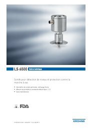
<strong>IFC</strong> <strong>100</strong> Technical Data<strong>sheet</strong>Signal converter for electromagnetic flowmeters• Simple and easy to install and start-up• Diagnostics of device and application• Extremely fast signal conversionThe documentation is only complete when used in combination with the relevantdocumentation for the sensor.© KROHNE 07/2009 - 4000040503 - TD <strong>IFC</strong> <strong>100</strong> R03 en
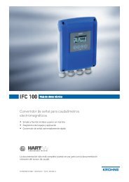
<strong>IFC</strong> <strong>100</strong>PRODUCT FEATURES 11.1 The more than economical solutionThe <strong>IFC</strong> <strong>100</strong> electromagnetic signal converter is designed to measure the flow velocity,conductivity, volume and mass flow of electrically conductive, liquid media.The signal converter can be combined with any measuring sensor, making it very widely used. Interms of available housing versions, there is a compact variant, in which the signal converter isconnected to the measuring sensor, as well as a 0° and 45° version. If the measuring point isdifficult to access or the ambient conditions prevent the use of the compact variant, the signalconverter is available in a wall-mounted housing.The <strong>IFC</strong> <strong>100</strong> was designed for applications requiring an economical measuring solution with ahigh level of technology.(signal converter in wall-mounted housing)1 Large backlit graphic display with 4 push buttons to operate the signal converter without having to open the housing2 Supply voltage: <strong>100</strong>...230 VAC (standard) and 24 VDC or 24 VAC/DC (optional)07/2009 - 4000040503 - TD <strong>IFC</strong> <strong>100</strong> R03 enwww.krohne.com3
1 PRODUCT FEATURES<strong>IFC</strong> <strong>100</strong>Highlights• Simple installation and start-up• Available inputs and outputs: Current output (incl. HART ® ), pulse/frequency output, statusoutput and control input• Large backlit graphic display with intuitive operation• A variety of operating languages integrated as standard• Maintenance free• Excellent price/performance ratio• Extremely quick signal conversionIndustries• Water & Wastewater• Agriculture• Heating, Ventilation & Air Conditioning (HVAC)• Machinery• Power plantsApplications• Measuring homogeneous media• Water distribution networks and spray-irrigation systems• Water treatment• Environmental technology4www.krohne.com07/2009 - 4000040503 - TD <strong>IFC</strong> <strong>100</strong> R03 en
<strong>IFC</strong> <strong>100</strong>PRODUCT FEATURES 11.2 Options and variantsModular converter conceptDespite its somewhat different appearance, the<strong>IFC</strong> <strong>100</strong> has many of the same functions as its "bigbrother" <strong>IFC</strong> 300. Diagnostic function, conductivitymeasurement and simple navigation to name but afew.This latest member of the converter family also hasa large number of fully-developed functions:• various power supply versions (AC, DC, AC/DC)• HART ® as standard• optional Ex version available(Compact version as 45° version)Compact design in various versionsThe <strong>IFC</strong> <strong>100</strong> C in the 0° version is ideal forinstallation in vertical pipelines.On the other hand, the 45° version improves thereadability of the display in specific applications.The backlit display provides excellent readabilityfrom long distances. The 4 push buttons makeoperation, start-up and configuration simple.In the 0° version, the signal converter can be rotatedin 90° increments allowing for customer-specificinstallation position. The 45° version can only berotated in 180° increments.(Compact version as 0° version)07/2009 - 4000040503 - TD <strong>IFC</strong> <strong>100</strong> R03 enwww.krohne.com5
1 PRODUCT FEATURES<strong>IFC</strong> <strong>100</strong>Remote version in wall-mounted housingFor temperature effects, vibration or in places thatare difficult to access, remote installation is possiblewith the <strong>IFC</strong> <strong>100</strong> W.A signal cable is used to connect the measuringsensor and the converter for the purposes of powersupply and signal processing.The electronics can be used in all housing versionswithout having to be reconfigurated.(signal converter in wall-mounted housing)DiagnosticsThe <strong>IFC</strong> <strong>100</strong> has been equipped with a wide variety ofdiagnostic tools for device function and applicationcheck.• Conductivity measurement• Electrode error• Process or ambient temperature too high6www.krohne.com07/2009 - 4000040503 - TD <strong>IFC</strong> <strong>100</strong> R03 en
<strong>IFC</strong> <strong>100</strong>PRODUCT FEATURES 11.3 Signal converter / measuring sensor combination possibilitiesMeasuring sensor Measuring sensor + measuring converter <strong>IFC</strong> <strong>100</strong>1.4 Measuring principleAn electrically conductive fluid flows inside an electrically insulating pipe through a magneticfield. This magnetic field is generated by a current, flowing through a pair of field coils. Inside ofthe fluid, a voltage U is generated:U = v * k * B * Din which:v = mean flow velocityk = factor correcting for geometryB = magnetic field strengthD = inner diameter of flow meterCompact (0°/45° version)Remote wall-mountedhousingOPTIFLUX <strong>100</strong>0 OPTIFLUX 1<strong>100</strong> C OPTIFLUX 1<strong>100</strong> WOPTIFLUX 2000 OPTIFLUX 2<strong>100</strong> C OPTIFLUX 2<strong>100</strong> WOPTIFLUX 4000 OPTIFLUX 4<strong>100</strong> C OPTIFLUX 4<strong>100</strong> WOPTIFLUX 5000 OPTIFLUX 5<strong>100</strong> C OPTIFLUX 5<strong>100</strong> WOPTIFLUX 6000 OPTIFLUX 6<strong>100</strong> C OPTIFLUX 6<strong>100</strong> WWATERFLUX 3000 WATERFLUX 3<strong>100</strong> C WATERFLUX 3<strong>100</strong> WThe signal voltage U is picked off by electrodes and is proportional to the mean flow velocity vand thus the flow rate q. A signal converter is used to amplify the signal voltage, filter it andconvert it into signals for totalising, recording and output processing.1 Induced voltage (proportional to flow velocity)2 Electrodes3 Magnetic field4 Field coils07/2009 - 4000040503 - TD <strong>IFC</strong> <strong>100</strong> R03 enwww.krohne.com7
2 TECHNICAL DATA<strong>IFC</strong> <strong>100</strong>2.1 Technical <strong>data</strong>• The following <strong>data</strong> is provided for general applications. If you require <strong>data</strong> that is morerelevant to your specific application, please contact us or your local representative.• Additional information (certificates, special tools, software,...) and complete productdocumentation can be downloaded free of charge from the website (Download Center).Measuring systemMeasuring principleApplication rangeFaraday's law of inductionContinuous measurement of current volume flow, flow velocity, conductivity, massflow (at constant density), coil temperature of the measuring sensorDesignModular designMeasuring sensorOPTIFLUX <strong>100</strong>0OPTIFLUX 2000OPTIFLUX 4000OPTIFLUX 5000OPTIFLUX 6000The measuring system consists of a measuring sensor and a signal converter.DN10...150 / 3/8…6"DN25...1200 / 1…48"DN2.5...1200 / 1/10…48"Flange: DN15...300 / ½…12"Sandwich: DN2.5...<strong>100</strong> / 1/10…4"DN2.5...150 / 1/10…6"WATERFLUX 3000 DN25...600 / 1...24"Signal converterCompact version (C)Remote version (W)OptionsOutputsTotalizerVerificationWith the exception of the OPTIFLUX <strong>100</strong>0 and WATERFLUX 3000 all measuringsensors are also available in an Ex-version.<strong>IFC</strong> <strong>100</strong> C (0° & 45° version)<strong>IFC</strong> <strong>100</strong> WAll signal converters are also available in Ex-versions.Current- (incl. HART ® ), pulse, frequency, status output and/or limit switch2 internal counters with a max. of 8 counter places (e.g. for counting volume and/ormass units)Integrated verification, diagnostic functions: measuring device, empty pipedetection, stabilization8www.krohne.com07/2009 - 4000040503 - TD <strong>IFC</strong> <strong>100</strong> R03 en
<strong>IFC</strong> <strong>100</strong>TECHNICAL DATA 2Display and user interfaceGraphic displayOperating elementsRemote controlDisplay functionsOperating menuLanguage display textsUnitsLC display, backlit white.Size: 128 x 64 pixels, corresponds to 59 x 31 mm = 2.32" x 1.22"Ambient temperatures below -25°C / -13°F, may affect the readability of the display.4 push buttons for operator control of the signal converter without opening thehousing.PACTware ® (incl. Device Type Manager (DTM)) (in preparation)HART ® Hand Held Communicator from Emerson Process (in preparation)AMS ® from Emerson Process (in preparation)PDM ® from Siemens (in preparation)All DTMs and drivers are available free of charge from the manufacturer's website.Setting the parameters using 2 measured value pages, 1 status page, 1 graphicspage (measured values and graphics are freely adjustable)English, French, German, Dutch, Polish, Portuguese, Danish, Spanish, Swedish,Slovenian, Italian (others on request)Metric, British and US units selectable as required from lists for volume / mass flowand counting, flow velocity, electrical conductivity, temperatureMeasuring accuracyReference conditionsMedium: waterTemperature: 20°C / 68°FPressure: 1 bar / 14.5 psiInlet section: ≥ 5 DNMaximum measuring error ±0.3% of the measured value ±1 mm/s, depending on the measuring sensorFor detailed information and accuracy curves, refer to chapter "Accuracy".Repeatability ±0.1%07/2009 - 4000040503 - TD <strong>IFC</strong> <strong>100</strong> R03 enwww.krohne.com9
<strong>IFC</strong> <strong>100</strong>TECHNICAL DATA 2Time constantFunctionSettings Set in increments of 0.1.Status output / limit switchFunction and settingsOperating <strong>data</strong>PassiveThe time constant corresponds to the elapsed time until 67% of the end value hasbeen reached according to a step function.0…<strong>100</strong> sAdjustable as automatic measuring range conversion, display of flow direction,counter overflow, error, switching point or empty pipe detectionValve control with activated dosing functionStatus and/or control: ON or OFFU ext ≤ 32 VDCI ≤ <strong>100</strong> mAopen:I ≤ 0.05 mA at U ext =32VDCclosed:U 0, max = 0.2 V at I ≤ 10 mAU 0, max = 2 V at I ≤ <strong>100</strong> mAModbus (in preparation)DescriptionModbus RTU, Master / Slave, RS485Address range 1…247Broadcast Supported with function code 16Supported Baudrate1200, 2400, 4800, 9600, 19200, 38400, 57600, 115200 BaudApprovals and certificatesCEThe device fulfils the statutory requirements of the EC directives. The manufacturercertifies that these requirements have been met by applying the CE marking.Non-ExStandardHazardous areasATEXOptional (OPTIFLUX 2<strong>100</strong> C and OPTIFLUX 4<strong>100</strong> C only)II 2 G Ex e [ia] mb IIC T4 (DN10...20; DN200...300; DN350...3000)II 2 G Ex d e [ia] mb IIC T4 (DN25...150)II 2 G Ex e [ia] mb q T4/T3 (DN25...150; DN200...300)II 2 D Ex tD A21 IP64 T120°C (all nominal sizes)Option (only version W)II 2 G Ex e [ia] mb IIC T4II 2 D Ex tD A21 IP64 T135°COther standards and approvalsShock and vibration resistance IEC 68-2-3Electromagnetic compatibility 2004/108/EC in conjunction with EN 61326-1 (A1, A2)(EMC)European Pressure Equipment PED 97/23 (only for compact versions)DirectiveNAMUR NE 21, NE 43, NE 5307/2009 - 4000040503 - TD <strong>IFC</strong> <strong>100</strong> R03 enwww.krohne.com13
2 TECHNICAL DATA<strong>IFC</strong> <strong>100</strong>2.2 Dimensions and weights2.2.1 HousingWall-mounted versionDimensions and weights in mm and kgWall-mountedversionDimensions [mm]a b c d e f g h i kWeight[kg]161 40 87.2 120 155 241 95.2 257 19.3 39.7 Std: 1.9Ex: 2.4Dimensions and weights in inches and lbWall-mountedversionDimensions [inch]a b c d e f g h i kWeight[lb]6.34 1.57 3.43 4.72 6.10 9.50 3.75 10.12 0.76 1.56 Std: 4.2Ex: 5.314www.krohne.com07/2009 - 4000040503 - TD <strong>IFC</strong> <strong>100</strong> R03 en
<strong>IFC</strong> <strong>100</strong>TECHNICAL DATA 2Compact 0° version1 4 x M 6Dimensions and weights in mm and kgDimensions and weights in inches and lbDimensions [mm]a b c d e f g hWeight[kg]0° version 161 40 155 81.5 257 - - Ø72 Std: 1.9Ex: 2.4Dimensions [inch]a b c d e f g hWeight[lb]0° version 6.34 1.57 6.1 3.21 10.12 - - Ø2.83 Std: 4.2Ex: 5.307/2009 - 4000040503 - TD <strong>IFC</strong> <strong>100</strong> R03 enwww.krohne.com15
2 TECHNICAL DATA<strong>IFC</strong> <strong>100</strong>Compact 45° version1 4 x M 6Dimensions and weights in mm and kgDimensions and weights in inches and lbDimensions [mm]a b c d e f g hWeight[kg]45° version 161 40 155 184 27.4 45° 186 Ø72 Std: 2.1Ex: 2.6Dimensions [inch]a b c d e f g hWeight[lb]45° version 6.34 1.57 6.10 7.24 1.08 45° 7.32 Ø2.83 Std: 4.6Ex: 5.716www.krohne.com07/2009 - 4000040503 - TD <strong>IFC</strong> <strong>100</strong> R03 en
<strong>IFC</strong> <strong>100</strong>TECHNICAL DATA 22.2.2 Mounting plate, wall-mounted versionDimensions in mm and inches[mm][inches]a Ø6.5 Ø0.26b 87.2 3.4c 241 9.507/2009 - 4000040503 - TD <strong>IFC</strong> <strong>100</strong> R03 enwww.krohne.com17
2 TECHNICAL DATA<strong>IFC</strong> <strong>100</strong>2.3 Flow tablesFlow rate in m/s and m 3 /hQ <strong>100</strong> % in m 3 /hv [m/s] 0.3 1 3 12DN [mm] Min. flow Nominal flow Max. flow2.5 0.005 0.02 0.05 0.214 0.01 0.05 0.14 0.546 0.03 0.10 0.31 1.2210 0.08 0.28 0.85 3.3915 0.19 0.64 1.91 7.6320 0.34 1.13 3.39 13.5725 0.53 1.77 5.30 21.2132 0.87 2.90 8.69 34.7440 1.36 4.52 13.57 54.2950 2.12 7.07 21.21 84.8265 3.58 11.95 35.84 143.3580 5.43 18.10 54.29 217.15<strong>100</strong> 8.48 28.27 84.82 339.29125 13.25 44.18 132.54 530.15150 19.09 63.62 190.85 763.40200 33.93 113.10 339.30 1357.20250 53.01 176.71 530.13 2120.52300 76.34 254.47 763.41 3053.64350 103.91 346.36 1039.08 4156.32400 135.72 452.39 1357.17 5428.68450 171.77 572.51 1717.65 6870.60500 212.06 706.86 2120.58 8482.32600 305.37 1017.90 3053.70 12214.80700 415.62 1385.40 4156.20 16624.80800 542.88 1809.60 5428.80 21715.20900 687.06 2290.20 6870.60 27482.40<strong>100</strong>0 848.22 2827.40 8482.20 33928.801200 1221.45 3421.20 12214.50 48858.0018www.krohne.com07/2009 - 4000040503 - TD <strong>IFC</strong> <strong>100</strong> R03 en
<strong>IFC</strong> <strong>100</strong>TECHNICAL DATA 2Flow rate in ft/s and US gallons/minQ <strong>100</strong> % in US gallons/minv [ft/s] 1 3.3 10 40DN [inches] Min. flow Nominal flow Max. flow1/10 0.02 0.09 0.23 0.931/8 0.06 0.22 0.60 2.391/4 0.13 0.44 1.34 5.383/8 0.37 1.23 3.73 14.941/2 0.84 2.82 8.40 33.613/4 1.49 4.98 14.94 59.761 2.33 7.79 23.34 93.361.25 3.82 12.77 38.24 152.971.5 5.98 19.90 59.75 239.022 9.34 31.13 93.37 373.472.5 15.78 52.61 159.79 631.163 23.90 79.69 239.02 956.094 37.35 124.47 373.46 1493.845 58.35 194.48 583.24 2334.176 84.03 279.97 840.29 3361.178 149.39 497.92 1493.29 5975.5710 233.41 777.96 2334.09 9336.3712 336.12 1120.29 3361.19 13444.7714 457.59 1525.15 4574.93 18299.7316 597.54 1991.60 5975.44 23901.7618 756.26 2520.61 7562.58 30250.3420 933.86 3112.56 9336.63 37346.5324 1344.50 4481.22 13445.04 53780.1528 1829.92 6099.12 18299.20 73196.7932 2390.23 7966.64 23902.29 95609.1536 3025.03 <strong>100</strong>82.42 30250.34 12<strong>100</strong>1.3740 3734.50 12447.09 37346.00 149384.0148 5377.88 17924.47 53778.83 215115.3007/2009 - 4000040503 - TD <strong>IFC</strong> <strong>100</strong> R03 enwww.krohne.com19
2 TECHNICAL DATA<strong>IFC</strong> <strong>100</strong>2.4 Measuring accuracyReference conditions• Medium: water• Temperature: 20°C / 68°F• Pressure: 1 bar / 14.5 psi• Inlet section: ≥ 5 DNX [m/s]: flow velocityY [%]: deviation from the actual measured value (mv)DN [mm] DN [inches] Accuracy CurveOPTIFLUX 2<strong>100</strong> / 4<strong>100</strong> / 5<strong>100</strong> / 6<strong>100</strong> 10…1200 3/8…48 0.3% of mv + 1 mm/s 1OPTIFLUX 1<strong>100</strong> 10…150 3/8…6 0.4% of mv + 1 mm/s as 1 + 0.1%OPTIFLUX 4<strong>100</strong> / 5<strong>100</strong> / 6<strong>100</strong> 2.5…6 1/10…1/4WATERFLUX 3<strong>100</strong> 25...600 1...24 0.3% of mv + 1 mm/s 120www.krohne.com07/2009 - 4000040503 - TD <strong>IFC</strong> <strong>100</strong> R03 en
<strong>IFC</strong> <strong>100</strong>INSTALLATION 33.1 Intended useThe electromagnetic flowmeters are designed exclusively to measure the flow and conductivityof electrically conductive, liquid media.For devices used in hazardous areas, additional safety notes apply; please refer to the Exdocumentation.If the device is not used according to the operating conditions (refer to chapter "Technical <strong>data</strong>),the intended protection could be affected.3.2 Installation specificationsThe following precautions must be taken to ensure reliable installation.• Make sure that there is adequate space to the sides.• Protect the signal converter from direct sunlight and install a sun shade if necessary.• Signal converters installed in control cabinets require adequate cooling, e.g. by fan or heatexchanger.• Do not expose the signal converter to intense vibration. The flowmeters are tested for avibration level in accordance with IEC 68-2-3.3.3 Mounting of the compact versionThe signal converter is mounted directly on the measuring sensor. For installation of theflowmeter, please observe the instructions in the supplied product documentation for themeasuring sensor.07/2009 - 4000040503 - TD <strong>IFC</strong> <strong>100</strong> R03 enwww.krohne.com21
3 INSTALLATION<strong>IFC</strong> <strong>100</strong>3.4 Mounting the wall-mounted housing, remote versionAssembly materials and tools are not part of the delivery. Use the assembly materials and toolsin compliance with the applicable occupational health and safety directives.3.4.1 Wall mountingFigure 3-1: Mounting the wall-mounted housing1 Prepare the holes with the aid of the mounting plate. For further information refer to Mountingplate, wall-mounted version on page 17.2 Fasten the device securely to the wall with the mounting plate.22www.krohne.com07/2009 - 4000040503 - TD <strong>IFC</strong> <strong>100</strong> R03 en
<strong>IFC</strong> <strong>100</strong>INSTALLATION 3Mounting multiple devices next to each other[mm][inches]a Ø6.5 Ø0.26b 87.2 3.4c 241 9.5d 310 12.2e 257 10.107/2009 - 4000040503 - TD <strong>IFC</strong> <strong>100</strong> R03 enwww.krohne.com23
4 ELECTRICAL CONNECTIONS<strong>IFC</strong> <strong>100</strong>4.1 Important notes on electrical connectionElectrical connection is carried out in conformity with the VDE 0<strong>100</strong> directive "Regulations forelectrical power installations with line voltages up to <strong>100</strong>0 V" or equivalent national regulations.• Use suitable cable entries for the various electrical cables.• The sensor and converter are configured together in the factory. For this reason, pleaseconnect the devices in pairs. Ensure that the sensor constant GK/GKL (see type plates) areidentically set.• If delivered separately or when installing devices that were not configured together, set theconverter to the DN size and GK/GKL of the sensor.4.2 Preparing the signal and field current cablesAssembly materials and tools are not part of the delivery. Use the assembly materials and toolsin compliance with the applicable occupational health and safety directives.4.2.1 Signal cable A (type DS 300), construction• Signal cable A is a double-shielded cable for signal transmission between the measuringsensor and signal converter.• Bending radius: ≥ 50 mm / 2"Figure 4-1: Construction of signal cable A1 Stranded drain wire (1) for the inner shield (10), 1.0 mm 2 Cu / AWG 17 (not insulated, bare)2 Insulated wire (2), 0.5 mm 2 Cu / AWG 203 Insulated wire (3), 0.5 mm 2 Cu / AWG 204 Outer sheath5 Insulation layers6 Stranded drain wire (6) for the outer shield (60)24www.krohne.com07/2009 - 4000040503 - TD <strong>IFC</strong> <strong>100</strong> R03 en
<strong>IFC</strong> <strong>100</strong>ELECTRICAL CONNECTIONS 44.2.2 Length of signal cable AFor temperatures of the medium above 150°C / 300°F, a special signal cable and a ZDintermediate socket are necessary. These are available including the changed electricalconnection diagrams.Measuring sensor Nominal size Min. electricalconductivityDN [mm] [inches] [µS/cm]OPTIFLUX <strong>100</strong>0 F 10...150 3/8...6 5 A1OPTIFLUX 2000 F 25...150 1...6 20 A1200...1200 8...48 20 A2OPTIFLUX 4000 F 2.5...150 1/10...6 1 A1200...1200 8...48 1 A2OPTIFLUX 5000 F 2.5...<strong>100</strong> 1/10...4 1 A1150...250 6...10 1 A2OPTIFLUX 6000 F 2.5...150 1/10...6 1 A1WATERFLUX 3000 F 25...600 1...24 20 A1Curve for signalcable AFigure 4-2: Maximum length of signal cable A1 Maximum length of signal cable A between the measuring sensor and signal converter [m]2 Maximum length of signal cable A between the measuring sensor and signal converter [ft]3 Electrical conductivity of the medium being measured [μS/cm]07/2009 - 4000040503 - TD <strong>IFC</strong> <strong>100</strong> R03 enwww.krohne.com25
4 ELECTRICAL CONNECTIONS<strong>IFC</strong> <strong>100</strong>4.2.3 Connection diagram for signal and field current cableThe device must be grounded in accordance with regulations in order to protect personnelagainst electric shocks.• A shielded two-wire copper cable is used as the field current cable. The shielding MUST beconnected in the housing of the measuring sensor and signal converter.• The outer shield (60) is connected in the terminal compartment of the measuring sensordirectly via the shield and a clip.• Bending radius of signal and field current cable: ≥ 50 mm / 2"• The following illustration is schematic. The positions of the electrical connection terminalsmay vary depending on the housing version.Figure 4-3: Connection diagram for signal and field current cable1 Electrical terminal compartment in signal converter2 Signal cable A3 Field current cable C4 Electrical terminal compartment in measuring sensor5 Functional ground FE26www.krohne.com07/2009 - 4000040503 - TD <strong>IFC</strong> <strong>100</strong> R03 en
<strong>IFC</strong> <strong>100</strong>ELECTRICAL CONNECTIONS 44.3 Connecting the powerThe device must be grounded in accordance with regulations in order to protect personnelagainst electric shocks.• The housings of the devices, which are designed to protect the electronic equipment fromdust and moisture, should be kept well closed at all times. Creepage distances andclearances are dimensioned to VDE 0110 and IEC 664 for pollution severity 2. Supply circuitsare designed for overvoltage category III and the output circuits for overvoltage category II.• Fuse protection (I N ≤ 16 A) for the infeed power circuit, and also a disconnecting device(switch, circuit breaker) to isolate the signal converter must be provided.Figure 4-4: Terminal compartment for power1 Retaining band of the cover2 Cable entry power supply remote version3 Cable entry power supply compact versionVersion overviewVersion Non-Ex Ex<strong>100</strong>...230 VAC Standard Optional12...24 VDC Standard -24 VAC/DC - Standard07/2009 - 4000040503 - TD <strong>IFC</strong> <strong>100</strong> R03 enwww.krohne.com27
4 ELECTRICAL CONNECTIONS<strong>IFC</strong> <strong>100</strong>• Open the cover of the electrical terminal compartment by pressing down and pulling forwardsat the same time.Figure 4-5: Power supply connection1 <strong>100</strong>...230 VAC (-15% / +10%), 8 VA2 24 VDC (-55% / +30%), 4 W3 24 VAC/DC (AC: -15% / +10%; DC: -25% / +30%), 7 VA and 4 W• Close the cover after the power has been connected.<strong>100</strong>...230 VAC (tolerance range: -15% / +10%)• Note the power supply voltage and frequency (50...60 Hz) on the nameplate.240 VAC + 5% is included in the tolerance range.12...24 VDC (tolerance range: -55% / +30%)• Note the <strong>data</strong> on the nameplate!• When connecting to functional extra-low voltages, provide a facility for protective separation(PELV) (acc. to VDE 0<strong>100</strong> / VDE 0106 and IEC 364 / IEC 536 or relevant national regulations).12 VDC - 10% is included in the tolerance range.24 VAC/DC (tolerance range: AC: -15% / +10%; DC: -25% / +30%)• AC: Note the power supply voltage and frequency (50...60 Hz) on the nameplate.• DC: When connecting to functional extra-low voltages, provide a facility for protectiveseparation (PELV) (acc. to VDE 0<strong>100</strong> / VDE 0106 and IEC 364 / IEC 536 or relevant nationalregulations).12 V is not included in the tolerance range.28www.krohne.com07/2009 - 4000040503 - TD <strong>IFC</strong> <strong>100</strong> R03 en
<strong>IFC</strong> <strong>100</strong>ELECTRICAL CONNECTIONS 44.4 Overview of outputs4.4.1 Description of the CG numberFigure 4-6: Marking (CG number) of the electronics module and output variants1 ID number: 02 ID number: 0 = standard; 9 = special3 Power supply4 Display (language versions)5 Output version4.4.2 Fixed, non-alterable output versionsThis signal converter is available with various output combinations.• The grey boxes in the tables denote unassigned or unused connection terminals.• In the table, only the final digits of the CG-No. are depicted.• Connection terminal A+ is only operable in the basic output version.CG-No.Connection terminalsA+ A A- C C- D D-Basic outputs (I/O) Standard1 0 0 I p + HART ® passive 1 S p passive P p / S p passive 2I a + HART ® active 11 function changed by reconnecting2 changeableDescription of used abbreviationsI a I p Current output active or passiveP pS pPulse/frequency output passiveStatus output / limit switch passive07/2009 - 4000040503 - TD <strong>IFC</strong> <strong>100</strong> R03 enwww.krohne.com29
4 ELECTRICAL CONNECTIONS<strong>IFC</strong> <strong>100</strong>4.5 Laying electrical cables correctlyFigure 4-7: Protect housing from dust and water1 For compact versions with nearly horizontally-oriented cable entries, lay the necessary electriccables with a drip loop as shown in the illustration.2 Tighten the screw connection of the cable entry securely.3 Seal cable entries that are not needed with a plug.30www.krohne.com07/2009 - 4000040503 - TD <strong>IFC</strong> <strong>100</strong> R03 en
<strong>IFC</strong> <strong>100</strong>NOTES 507/2009 - 4000040503 - TD <strong>IFC</strong> <strong>100</strong> R03 enwww.krohne.com31
KKKKROHNE product overview© KROHNE 07/2009 - 4000040503 - TD <strong>IFC</strong> <strong>100</strong> R03 en - Subject to change without notice.• Electromagnetic flowmeters• Variable area flowmeters• Ultrasonic flowmeters• Mass flowmeters• Vortex flowmeters• Flow controllers• Level meters• Temperature meters• Pressure meters• Analysis products• Measuring systems for the oil and gas industry• Measuring systems for sea-going tankersHead Office KROHNE Messtechnik GmbHLudwig-Krohne-Str. 5D-47058 Duisburg (Germany)Tel.:+49 (0)203 301 0Fax:+49 (0)203 301 10389info@krohne.deThe current list of all KROHNE contacts and addresses can be found at:www.krohne.com