Moog G040-124-001 DDV Tester
Moog G040-124-001 DDV Tester
Moog G040-124-001 DDV Tester

Create successful ePaper yourself
Turn your PDF publications into a flip-book with our unique Google optimized e-Paper software.
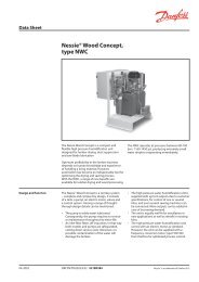
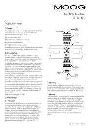
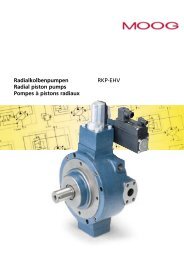
m<strong>G040</strong>-<strong>124</strong>-<strong>001</strong><strong>DDV</strong> <strong>Tester</strong>DESCRIPTIONThe <strong>Moog</strong> <strong>G040</strong>-<strong>124</strong>-<strong>001</strong> Direct Drive Valve (<strong>DDV</strong>) <strong>Tester</strong>tests a <strong>DDV</strong>, without the need for electrical power orhydraulic supply. Internal rechargeable batteries eliminatethe need for external electrical power by powering the<strong>Tester</strong> as well as the valve.Testing is simple and straightforward. Plug the <strong>Tester</strong>’sconnector into the valve, rotate the command potentiometerand observe the spool LED display following thecommand. A hydraulic supply is not necessary because theforce to position the spool is generated electrically by thevalve’s linear force motor.A measurement of the valve’s operation can be made with adigital multimeter on the command and spool test points.More test points, connected directly to the valve’s connectorpins, aid in trouble-shooting. A test point that gives anoutput proportional to the valve’s supply current is also veryuseful in trouble-shooting.FEATURES• Fully tests a Direct Drive Valve (<strong>DDV</strong>)• All command signals catered for• LED display of spool position• Normalised ±10V command and spool test points• Valve pin test points• Valve supply current test point• Internal rechargeable batteries power the valveand <strong>Tester</strong>Page 1 of 4: C70301 Rev 04.05
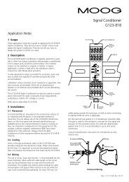
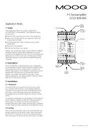
G--OPERATING INSTRUCTIONSThe numbers in bold refer to the corresponding area in figure 1.1. Supply and battery chargingTurn on the <strong>Tester</strong> with the on/off switch in 1. The Vs LEDindicates correct internal supplies.If the Lo.V LED is illuminated, do not use the <strong>Tester</strong>; chargeits batteries. Plug the charger into the charge socket in 1 andcharge until the charger LED is green.The Hi.I LED illuminates if the supply current to the valve isgreater than ±250mA. This current will occur during normaloperation. The warning is provided to maximise battery lifeby alerting the user to occasions when high current may notbe necessary.2. Valve connectorPlug the valve connector, 2, into the valve.3. CommandSelect the type of command with the command selector in 3.The command type is stamped on the valve name plate. Ifthis is not present, or cannot be read, determine the signaltype from the model or box-car number.Vary the command with the command potentiometer andobserve the spool LED display in 4 following the command.6. Other valvesThe <strong>Tester</strong> can also be used to test +24V, 6+PE proportionalvalves. Pin C on the valve connector is wired to 24V toprovide the enable signal required by proportional valves.7. Battery replacement• Remove the six screws on the side panels and unclip thefront panel from the base. The side panels will need to belevered apart with a screwdriver to do this.• Disconnect the battery leads from the circuit card andunclip the battery cover.• Note the battery orientation and place the new batteriesin the same way.• When reassembling, be careful not to pinch any internalwires.• Ensure the new batteries receive a full charge beforeusing.Figure 14. SpoolFor precise confirmation of correct valve operation, measureat the ±10V command and ±10V spool test points. Measurewith respect to the 0V test point in 1. Without flow, thespool test point signal will follow the command, unless thespool movement is restricted.5. Test pointsThe test points of 5 enable direct measurement of signals onthe valve connector pins and an indirect measurement of thesupply current to the valve. The I A valve current test pointscaling is 1V = 1A. High current draw can indicate a stickingspool, due to contamination or physical damage to the spoolor bushing.21543Page 2 of 4: C70301 Rev 04.05
G--SPECIFICATIONSCommand outputs: 0 to ±10V @ ±10mA max0 to ±10mA @ 1k load min4-20mA @ 0 to 500 Ohm loadSpool input:Supply to valve:4-20mA, 500 Ohm load24V nominal @ 2.1A maxTest points: Command, 0 to ±10VSpool, 0 to ±10VA, valve supply pin, 22 to 26VI A, valve supply current, 1V = 1APE, protective earthF, spool signal, 2 to 10VD, command signal0V, zero volts (ground) referenceLEDs:Battery:Charge time:Operate time:Operating temp: 0 to 40ºCDimensions:Cable length:Weight:EMC:Battery charger:Lo.V, threshold = 22VHi.I, threshold = ±250mAVs, ±15V internal supply > ±12VSealed lead acid, 2 x 12V, 0.8AHr4.5 hours typical from 22V40 minutes @ 500mA supply to valve2 hours for typical use80H x 105W x 180DDepth to end of cable gland is 2402 m1.5 kgCE markedEN61000-6-3 emissionEn61000-6-2 immunity240mA @ 29.4V (red LED)27.4V float (green LED)90-264VAC, 47-63HzAC connector, 2 pin IEC320-C7–25 to 40ºCCE markedEN50081.1 emissionEN50082.1 immunityORDERING INFORMATION<strong>G040</strong>-120-<strong>001</strong> <strong>DDV</strong> <strong>Tester</strong> with batteries installed anda battery charger (AC power lead notincluded)C70591 Charger only (AC power lead not included)C70589 Replacement battery (2 required)INTERNET DATAFor the latest version of this Data Sheet, please refer to the<strong>Moog</strong> website www.moog.com/valvetestersPage 3 of 4: C70301 Rev 04.05
<strong>DDV</strong> SPECIFICATIONG--VALVE ELECTRONICS WITH SUPPLY VOLTAGE 24 VOLT AND 6+PE POLE CONNECTORCommand signal 0 to ±10 mA floating,Valves with current command inputThe spool stroke of the valve is proportional to the currentflowing between pins D and E.100% valve opening P A and B T is achieved atI D = +10 mA. At 0 mA command the spool is in centredposition. The input pins D and E are inverting. Either pin Dor E is used according to the required operating direction. Itis necessary to connect the unused pin to signal ground inthe cabinet.Command signal 0 to ±10 mA,Valves with current command inputThe spool stroke of the valve is proportional to (I D – I E ).100% valve opening P A and B T with (I D – I E ) = +10 mA.Either pin D or E is used according to the desired flowphasing. The unused pin is left unconnected. R in (D to B) =200Ω. R in (E to B) = 200Ω.Command signal 0 to ±10 V,Valves with voltage command inputThe spool stroke of the valve is proportional to (U D – U E ).100% valve opening P A and B T is achieved at(U D – U E ) = +10 V.At 0 V command the spool is in centred position. The inputstage is a differential amplifier. When only one commandsignal is connected to the valve it is necessary to connect theunused pin to signal ground in the cabinet, according to therequired operating direction.Command signal 4 to -20 mA,Valves with current command inputThe spool stroke of the valve is proportional to I D minusthe centre null current of 12 mA. 100% valve opening P Aand B T with I D = +20 mA. 100% valve opening P B andA T with I D = +4 mA. Use pin D as signal input. Pin E is leftunconnected. R in (D to B) = 200Ω.Actual value 4 to 20 mAThe actual spool position value can be measured at pin F (seediagram below). This signal can be used for monitoring andfault detection purposes.The spool stroke range corresponds to 4 to 20 mA.The centred position is at 12 mA. 20 mA corresponds to 100%valve opening P A and B T.Circuit diagram for measurement of actual value I F(position of spool) for valves with 6+PE pole connector4-20 mAValve sideI outR L = 500Ω (0.25 W)U outActual valueU out : 2-10 VThe position signal output 4 to 20 mA allows the detectionof a cable break when I F = 0 mA.For failure detection purposes it is necessary to connectpin F of the mating connector and route this signal to thecontrol cabinet.WIRING FOR VALVES WITH 6+PE POLE CONNECTOR(to EN 175201 Part 804 1 ), and mating connector (type R and S, metal shell) with leading protective earth connection ().See also Application Note AM 426 E.ValveConnectorMatingconnectorCabinet sideR in (D to E) = 200totoR in (D to E) = 10 K1) formerly DIN 43563<strong>Moog</strong> Australia Pty Ltd • Australia +61-3-9561-6044 • USA +1-716-655-3000 • Germany +49-7031-622-0 • Japan +81-463-55-3615For the location nearest you, contact www.moog.com/worldwide. For disclaimers, see www.moog.com/literature/disclaimers.Page 4 of 4: C70301 Rev 04.05