5-bands FM digital audio processor - Solidyne
5-bands FM digital audio processor - Solidyne
5-bands FM digital audio processor - Solidyne

You also want an ePaper? Increase the reach of your titles
YUMPU automatically turns print PDFs into web optimized ePapers that Google loves.
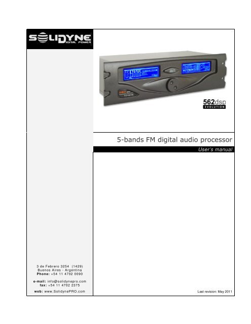
5-<strong>bands</strong> <strong>FM</strong> <strong>digital</strong> <strong>audio</strong> <strong>processor</strong>User’s manual3 de Febr ero 3254 (1429)Buen os Aires - ArgentinaPhone: +54 11 4702 0090e-mail: inf o@solidyn epro.comfax: +54 11 4702 2375web: www.Solidyn ePRO.com Last revision: May 2011
Página 2procesador para radiodifusión - SOLIDYNE 562dsp
Chapter 1Quick installation guide1.1 Basic connection and settingsCONECTIONSSETTINGSPower supplyControlsBefore plug in; check the position of theAC VOLTAGE selector, on the rear panel(200-240 V, 50/60Hz; or 100-130 V, accordsto correspond).All settings values are entered using aJOG Wheel. Turn the JOG to selectoptions and to change values. Pressingbriefly the JOG, confirms an option.Pressing and holding the JOG (around onesecond), go to the main menu. Eachscreen graphically indicates the actionsavailable with the JOG (see figure).InputsOutputsAnalogical <strong>audio</strong> inputs are balanced, usingXLR (female) connectors. Connect thePROGRAM OUTPUTS of your console tothese inputs. Take care of not invert thephase of the channels.Optionally; the 562dsp has <strong>digital</strong> AES-3(AES/EBU) input, for <strong>digital</strong> consoles or links.This input supports 16/24 bits and samplerates from 30 up to 96 KH. When the <strong>digital</strong>input is used, we recommend connecting theanalogical inputs too. 562dsp will switchautomatically to these inputs in case of failureon the AES-3 signal.InputProgramsThe default input level is +4 dBu. If yourconsole manages a different level, youmust adjust the <strong>processor</strong> input level.Press briefly the JOG to enter to the mainmenu. Choose the option “Setup Input”and adjust the level according to thenominal specified on your console.Your radio already is on the air with thesound of the <strong>Solidyne</strong> 562dsp. At thispoint, you must be anxious to listen what562dsp is able to do with the sound of yourradio on the air… to begin we will explainbriefly how to select the factory presets.Tunes your radio in a good <strong>audio</strong>equipment and do the following:Connects the 562’s MPX output (BNC) toyour transmitter exciter.Turn the JOG. Note on the screen howthe different presets programs nameschanges. Pressing briefly the wheel loadthe program, changing the processingand the sound on the air.Power onThe unit has an ON/OFF switch on the rearpanel. The main screen Hill show a welcomesplash on start up; and then will load the lastused program.The 15 PRESET PROGRAMS can not bechanged. You have 15 USER MEMORIESto create your own adjustments. You canstart copying a preset program to a usermemory, and soon modifying it.SOLIDYNE 562dsp EVOLUTION – <strong>FM</strong> broadcast <strong>digital</strong> <strong>processor</strong> Page 5
1.2 Brief diagram for general connections1. If your computer does not have serialport; you can use a RS232 to USBadapter to connect the 562dsp on a USBport.In units with option RDS, you need toconnect a computer to the <strong>processor</strong> forRDS programming. This connection canbe not permanent (in case that a fixedtext is transmitted; it is stored into RDSmemory).2. When the <strong>processor</strong> connects to theconsole using the <strong>digital</strong> inputs, it’sconvenient to make the analogicalconnection too. In case of fault in the<strong>digital</strong> signal, 562dsp changes to theanalogical inputs automatically.3. In this example a RF connection wasused to transport the MPX signal fromthe <strong>processor</strong> to the transmitter, whichassumes installed in a build far from thestudies.In other configurations, the <strong>processor</strong>locates in the transmitting plant and a<strong>digital</strong> link is used to send the <strong>audio</strong>(multiple sends can be used for backup).In this case, the remote control of562dsp can be implemented through adata channel of the link that allowssending RS-232 data.1.3 Understanding the main screenNext you will see an overview on the 562dsp mainscreens. Later each processing stages and itssettings screens are fully analyzed.When the unit starts up; the boot screen appearson both screens showing the current version of thefirmware. Once started, the unit presents the mainscreen at the left, and the main menu at the right.Nextt, the main screen is described briefly asintroduction to the 562dsp graphical environment.The progressive bars show the action of several<strong>processor</strong> stages. The name of the current presetand state of inputs and outputs also appears onthis screen. From left to right you find: The input VU meters (L & R). Below the vumetersan overload (OVL) warning can appear, ifthe input level reach 8 dB before the “<strong>digital</strong>clipping” level (@ +18dBm). This warning turns offlast 5 seconds when the “clipping” conditiondisappears. AGC bar shows the action of the AutomaticGain Control, which fits the input gain so that thesignal arrives at the processing stages withconstant level. If the signal from the consolePage 6<strong>FM</strong> broadcast <strong>digital</strong> <strong>processor</strong> - SOLIDYNE 562dsp EVOLUTION
Water HeatersFlat RateSchedule2/9/07TIME ALLOWANCE SCHEDULE in hoursReplacement of: Standard Pilot Electronic IgnitionModelModelAccess Door.........................................................................................................30 ...........................................................................................30 ......................................................Circuit Board....................................................................................................N/A ...........................................................................................50 ......................................................Complete Water Heater ........................................................1.50 ......................................................................................1.75 * ..................................................Drain Valve or Plug.................................................................................30 ...........................................................................................30 * ..................................................Electric On-Off Switch ................................................................N/A ...........................................................................................50 * ..................................................Heating Element..................................................................................1.00* ......................................................................................1.00 * ..................................................Inner Tank ............................................................................................................2.00 ......................................................................................2.30 ......................................................Main Burner...........................................................................................................50 ...........................................................................................50 ....................................................Mixing Valve ......................................................................................................N/A ...........................................................................................50 ....................................................Wall Switch..........................................................................................................N/A ...........................................................................................75 ......................................................Pilot Assembly .............................................................................................50 ........................................................................................N/A ......................................................Pilot Ignitor Module .............................................................................50 ........................................................................................N/A ......................................................Pressure-Temp. Relief Valve .............................................50 ...........................................................................................50 * ..................................................Relay ................................................................................................................................N/A ...........................................................................................50 * ..................................................Solenoid Valve..............................................................................................N/A ...........................................................................................50 ......................................................Spark & Probe Assembly......................................................N/A ...........................................................................................50 ......................................................Thermal Cut Off ........................................................................................N/A ...........................................................................................30 ......................................................Thermostat & E.C.O. ......................................................................N/A ...........................................................................................50 * ..................................................Thermostat-electric...............................................................................50 ...........................................................................................50 ......................................................Thermostat-gas ......................................................................................1.00 ........................................................................................N/A ......................................................* indicates time allowed for Electric/Marine unitsNote: Warranty claims must be filed and received within six months from the date of repair.Claims received beyond this time frame will not be considered for warranty payment.All flat rates include diagnostic time and when applicable, gas leak test.IV
THIS PAGE INTENTIONALLY LEFT BLANKPage 8<strong>FM</strong> broadcast <strong>digital</strong> <strong>processor</strong> - SOLIDYNE 562dsp EVOLUTION
Chapter 2Advanced installation2.1 Power supply• The AC voltage variation must stay smaller to10%. Otherwise, uses an UPS.Always CHECK the correct position of theVOLTAGE SELECTOR (200/240 Volts o100/130 Volts, according to the country)AC wires do not have to be mixed with <strong>audio</strong>wires, especially with analogical ones.Remember that all <strong>audio</strong> installation musthave a trustworthy grounding. Werecommend accomplishing with theeffective norms - Article 810 of the NationalElectricity Code (NEC); ANSI/NFPA Nº 70-1984 inUSA; IRAM 2379 and 2281-3 in Argentina. Thisnorm provides information and guidelines for aconsistent grounding.2.1.2 On mounting• 562dsp can be mounted in a standard rack of19”; or can be used on a table. Rubber topsare provided with the unit. Do not place the uniton unstable surface or shelf; the apparatuscould fall, causing damages to someone and tobe damaged the unit.• The ambient temperature must stay between5ºC and 40ºC. Avoid direct solar ray incidenceon the <strong>processor</strong> or proximity of heat sources.• The openings and grooves allow the circulationof forced air impelled by the internal cooler.These openings do not have to be blocked norcovered, not to obstruct the refrigeration of theinternal components.• 562dsp has internal protection against RFfields, which allows locate it next totransmitters (AM or <strong>FM</strong>). Avoid strongelectromagnetic fields (power transformers, bigmotors, etc).2.2 Analogical <strong>audio</strong> connectionsInputs and outputs are electronically balanced.The inputs are “bridging” type, with impedancegreater than 10 KOhms. The connectors used, asis standard, are female XLR-3 for the inputs andmale for the outputs.Take specially care with the phase.• Use one pair shielded <strong>audio</strong> cables of GOODQUALITY, preferably with double shielding.The maximum length recommended is 30meters, although in special cases it is possibleto achieve 100 meters accepting a little loss athigh frequencies.• The connection of this cables are made as isstandard. See the following table:Balanced input/output connections:1 = GND2 = balanced positive phase (+)3 = balanced negative phase (-)SOLIDYNE 562dsp EVOLUTION – <strong>FM</strong> broadcast <strong>digital</strong> <strong>processor</strong> Page 9
Unbalanced connection:Inputs: Signal = 2;Ground = joint 1 and 3Outputs: Signal to pin 2; leave pin-3 unconnected.Ground = pin 12.3 Digital <strong>audio</strong> connectionsOptionally, the <strong>processor</strong> has <strong>digital</strong> AES-3inputs/outputs (models 562dsp/AES).The <strong>digital</strong> input supports:Resolution: 16 - 24 bitsSample rate: 30 KHz a 96 KHz.Internally 562dsp works at 24 bits/192 KHz, the<strong>digital</strong> signal is converted internally by a stagecalled “Resampler”.When the <strong>digital</strong> input is used, is convenient toconnect the analogical input too. In case of losingthe <strong>digital</strong> connection, the <strong>processor</strong> switchesautomatically to the analogical inputs. The inputmode is selected from the main menu choosingthe option “Setup Input”, as is explained later.S/PDIF: you can connect an S/PDIFoutput to the AES3 input of 562dspusing an S/PDIF to AES-3 adapter. Thefigure shows a compact adapter XLRBNC.AES-3 output has a resolution of 24 bits with asamplerate selectable between 48/96 KHz (see“3.2.2 – Output Setup”). The connector is maleXLR.AES3 input and output cables connect asfollowing:XLRSignal1 GND2 AES3 (1)3 AES 3 (2)AES-3 standard connection2.4 Console MICstartWith the 562dsp the current processing programcan changes when the study microphonesactivates. In this way you can use a processingspecially done for voices. The default adjustmentfor voices is the program “09: Voice Impact“.Obviously; you can copy and customize thisprogram.The commutation takes place when grounding theMICstart input. When this happens the <strong>processor</strong>exchanges the program and the access from theJOG wheel is blocked. When the MICStart input isopened, 562dsp returns to the previous program.“Console MICstart” uses an RCA connector. Withconsoles <strong>Solidyne</strong> 2300 series, MICstart isconnected directly to the Digisolid output of amicrophone channel (please refers to the manualof the console). In other consoles, the control canbe solved using the tally signal to activate a relay.Connect the relay contact directly to the RCA “MICStart”; and the coil in parallel to the tally light.The relay coil voltage depends on the voltagegives by the console.When the relay receives tension, the contact isclosed activating the Mic Start function in the<strong>processor</strong>. The voice’s program remains activewhile the contact is closed.This feature comes disabled from factory. Inorder to use it, you must enable the option “MICPROCESSING” in the <strong>processor</strong> setup (see “3.2.3- Processor Setup”).2.4 MPX outputThe MPX cable will be a RG-59 (coaxial 75 ohms),like the used for CATV. The output connector isBNC type. The maximum length recommended forthis cable is 25 m. Take care with the grounding;although this rarely is cause of problems becauseall <strong>Solidyne</strong> <strong>processor</strong>s have MPX differentialoutputs, that is to say, with the Earth isolated ofthe cabinet, to avoid ground loops.If some residual humming appears when thesystem is on the air; power off the <strong>processor</strong>. If thehumming disappears, check the input connectionsat the <strong>processor</strong>. If, however, the hummingcontinues (and only disappears unplugging theMPX cable), this indicates some problem with thegrounding.Page 10<strong>FM</strong> broadcast <strong>digital</strong> <strong>processor</strong> - SOLIDYNE 562dsp EVOLUTION
When enters to the transmitter through the MPXinput, make sure that the internal preemphasisnetwork IS DISCONNECTED (that is to say, flatresponse from 20 to 100 KHz). Contrary, whenuse an external stereo coder, make sure that thegenerator INCLUDES the preemphasis curve.This is thus since the 562dsp <strong>audio</strong> output DOESNOT INCLUDE preemphasis (only the MPX outputhas preemphasis).2.6 RDS CODER (OPTIONAL)Models 562dsp/RDS have internal RDS coder.RDS (Radio Data System) is a system developedby the European Broadcasters Union (EBU). Itallows adding to a conventional <strong>FM</strong> transmission,additional information by means of the inclusion ofsub-carrier that contains data.Their main applications are:1. The automatic tuning of the receiver to a radionetwork selected by the user, which, allows to listento a program, for example Classic Radio, during along trip by the route, with no need to tune manuallythe receiver to another station of the same radionetwork, when the reception happens to be deficientwhen leaving the zone on watch of a determinedstation.2. Show on the receiver screen the radio networkname that is tuned, for example Radio 1, and thekind of program: the general news, talk-show,sports, music, varieties, monk, etc.3. The automatic reception of information related to thetraffic. When this feature is selected the news haspriority on the traffic, so that the receiver willexchange, automatically, within a same network, tothe transmitter that emits information on the traffic,and once finished this information it will return to bein tune, automatically, the transmitter that previouslywas selected.2.6.1 RDS – PC connectionFor setup and control of RDS stage; the 562’s“RDS Data” port must be connected to acomputer, using a standard COM (RS-232).RDS DataPC2 (RxD) 3 (TxD)3 (TxD) 2 (RxD)4 (DTR) 6 (DSR)5 (GND) 5 (GND)6 (DSR) 4 (DTR)7 (RTS 8 (CTS)8 (CTS) 7 (RTS)Use a standard crossedserial cable (as known as“null-modem”). Two femaleDB-9 connectors arerequired. The following tableshows the diagram ofconnection, although only theconnections emphasized inbold are needed.The computer is used to transmit data to RDScoder. These data can change in real time, likewhen the names of the songs are transmitted, orcan be a fixed text that it is stored in the internalmemory of the RDS coder.In order to command the RDS coder; the software<strong>Solidyne</strong>-Magic RDS is required. This applicationis included in the 562dsp CD-ROM, provided withthe unit. Using this tool you will be able to start tosend RDS data. Please refer to the RDS help filefor detailed information on the software.2.6.2 Connecting to the transmitterThe models 562dsp/RDS do not require a specialconnection. MPX signal contains the RDSinformation that is injected directly to thetransmitter when connecting the MPX outputThe <strong>digital</strong> signal that it contains information RDS,is transmitted with a speed of 1187,5 bit/s andmodulates a subcarrier of 57 KHz, using themethod of Amplitude Modulation with suppressedcarrier, that is added to the multiplexedstereophonic signal; that it is sent to thetransmitter input. See the blocks diagram shown in“Chapter 1”.2.7 RS-232 remote controlThe connector PC CONTROL RS 232 allows toconnect a PC directly to the unit. Using thesoftware 562dsp VirtualRack you have full controlof the 562dsp. Please refer to “Chapter 5 –Remote control” to see details on the software.To conect the 562dsp to the PC use a standardRS232 serial cable (male-female DB-9).The computer must have one RS-232 available. Ifthe computer only has USB ports, a USB to RS-232 adapter can be used. Make sure to use agood quality adapter.2.8 Ethernet connection (OPTIONAL)RJ-45 Ethernet connector allows connecting the<strong>processor</strong> directly to a LAN. The unit can becontrolled via TCP/IP from another PC of the LANor via Internet; using the software <strong>Solidyne</strong>562dsp VirtualRack. See “Chapter 5 – RemoteControl” for software details.SOLIDYNE 562dsp EVOLUTION – <strong>FM</strong> broadcast <strong>digital</strong> <strong>processor</strong> Page 11
2.8.1 Installing and settingsBefore see the detailed explanation, an overviewon the settings procedure.a) Connect the 562dsp to the LAN (Hub, Switch orRouter) using a standard UTP cable.b) Check the IP address of the unit using “DSManager” software (this tool is available into thefolder “IP-Access” in the original CD).c) A PC will be used to run the software and to accessto the 562dsp hardware. We call to this PC “localterminal”. Install in the “local terminal” the <strong>Solidyne</strong>VirtualRack software, provided with the unit. If thereis a Firewall (by software or hardware) you mustenable port 1101 for the communication with the562dsp.d) Install in the “local terminal” the ‘Virtual Serial Port’.For make this, install the IP-ACCESS pack fromVirtual Rack 562 CD-ROM.e) Run the VRack5 software, it will explore the first 5ports to detect the <strong>audio</strong> <strong>processor</strong>, if not detectedyou must set the port number in the file serial.inif) To access from outside to the LAN, please refers to“2.8.3 –Accessing from Internet”Select the unit from the list and press the button[Settings]. Here you can define a new IP. In thisexample the local area network uses address like192.168.0.x, to accede from any terminal of thatnetwork to 562dsp/IP you need that IP address iscompatible. Assign a fixed IP that it does notgenerate conflicts with another terminal (in theexample 192.168.0.11).If you have a DHCP server you can obtain adynamic IP address, although if IP changesfrequently will require changes in the configurationof the clients (or in the LAN like for the accessfrom Internet).2.8.2.1 Set upConnect the 562dsp/IP to the LAN and turn on. Nextto the connector RJ45 a green LED will light. Ifamber LED lights then the network detected is of100Mbps.From setup CD-ROM install the IP-ACCESS pack,running \IP-ACCESS\Setup.exe. Once installed, run‘DS Manager’ tool, which provides in 562dsp/IP CD-ROM (folder IP-ACCESS). This tool will show allactive units connected to your LAN. Each unit has aMAC address that is unique and fixed; and an IPaddress that you can change freely.Assign the Gateway address (usually192.168.0.1), and the subnet mask. This isneeded if you wish to accede to the 562dsp/IPfrom outside of the LAN. If you don’t know thesevalues, contacts to your network administrator.The port used is 1101. You can change it ifconflicts with another application appear in theterminal client who uses the same port, but thisrarely occurs.¡NEVER PRESS THE BUTTON “INITIALIZE”! THISOPTION WILL CHANGE CRITICAL VALUES FROMFACTORY DEFAULTS.Critical default values:• In the section 'Connection', Transport Protocol= TCP (default value).• In the section 'Connection', Inband commands= 0 (dissabled) (default value).• In the section 'Serial Port', On the flycommands = 1 (ennabled) (default value). Ifdisable it applications can not set the baud rate.• In the section 'Serial Port', 'DRT Mode = 1Indicate connection status' (default value). It’sa critical value. If is changed communication willfail.Page 12<strong>FM</strong> broadcast <strong>digital</strong> <strong>processor</strong> - SOLIDYNE 562dsp EVOLUTION
All this values are set from factory. If you haveproblems with communication, check thesevariables. This values must be used when createthe Virtual Serial Port with VSP Port Manager.You can make a PING to verify the access to562dsp/IP hardware from the terminal. Anotheroption is to use the button [BUZZ] from the mainwindow of the DS Manager and you will see theLEDS of connector RJ45 to blink during onesecond. If you wish, you can set a password toblock modifications in your settings.2.8.2 Accessing from the LANThe client PC must have installed TCP/IPprotocol. If there is a Firewall (software orhardware) open the port 1101 for thecommunication with the 562dsp/IP.Install the driver `Virtual serial port' that allows tocommunicate with the <strong>processor</strong>. The tool is‘Connection Wizard', with this you must create anew serial-port IP address connection.Virtual serial port must install in each PC fromwhich it is desired to accede to the 562dsp/IP.Once installed the virtual serial port it must appearin the Windows Devices Manager.Now, double-clic on VSP to check the followingsettings:SOLIDYNE 562dsp EVOLUTION – <strong>FM</strong> broadcast <strong>digital</strong> <strong>processor</strong> Page 13
• Verificar que el protocolo de transporte seaTCP.• Que la opcion 'On-the-fly commands' estehabilitada (modo normal = Out of band).• Connection mode= Inmediatly.VirtualRack software automatically explores thefirst 5 ports to detect de 562dsp/IP hardware.Some routers offer the option `Virtual Server', thatis similar but more outpost than the ‘PortForwarding'. Soon you will have to install in yourPC (with ‘Connection Wizard') the virtual serialport. The IP address here entered is the externaladdress of the local area network.If the port number assigned was bigger than Port5; then you must declare the port manually byediting the configuration file serial.ini (VirtualRackfolder).2.8.3 Accessing from InternetIf you want access to a 562dsp/IP located outsideyour LAN; there are two possible ways in whichthe device can be connected to the network.The unit is connected directly to Internet: Inthis case you must enter the IP address assignedby the Internet provider (ISP).The unit is connected in another LAN (withshared Internet access): In order to accede froman remote PC to the LAN you must configure therouter of that LAN to redirect the packagesincoming by port 1101 to local IP addressassigned to 562dsp/IP (in our example192.168.0.11), and redirect also the port 65535.In order to know the external IP you must see thesettings information of your router. Now you canrun VirtualRack end user software so that that itcommunicates with your 562dsp/IP via Internet.The following is an illustrative example; the screenof present configuration depends on your router.Page 14<strong>FM</strong> broadcast <strong>digital</strong> <strong>processor</strong> - SOLIDYNE 562dsp EVOLUTION
Chapter 33.1 Basic actions3.1.1 Processing programs562dsp has 15 presets programs and 15 usermemories. Programs from 00 to 14 are programsmade by the engineers of <strong>Solidyne</strong>, ready to beon the air. There are different adjustments fordifferent music’s styles. Each program has a namethat identifies it (Jazz, Rock, Pop, Melodic, etc.)but the names are only indicatives; all musicstyles sounds well with any preset. Processingprograms are described with detail later.You can customize the programs copying it to theuser banks (15 to 29) and edit them. By default,user memories are “empty” (strictly speaking with“flat” processing adjustments). You can create anew adjustment changing the values of eachparameter on the user memory; or copying apreset to the user memory (recommended). See“4.3.1 – Copy programs”3.1.2 Modes of controlThe <strong>processor</strong> can be controlled of many ways:a) Can be manually controlled from the frontalpanel.b) Connecting the unit to a PC, you can createand edit programs using the 562dspVirtualRack software. This software allows tosave the 562’s programs in the Hard Disk (files.562) that you can send by mail, so that otherradios that you manages share the customizedadjustments. In addition; this software allowscreating a scheduling programming, tochange the processing program at certainhours from the day. Virtual Rack runs inbackground using very few resources. In factthis software can run on the On-Air computer.In this modality the programs can be chosenautomatically from the OnAir PC, using theautomation software <strong>Solidyne</strong> Audicom 7.This way you can use a specific processing foreach musical style.c) Models 562dsp/IP allows direct connectionto the LAN. You can run the softwareVirtualRack from another terminal to control the562dsp/IP.Starting up and operationWith the apropiate network configuration, youcan adjust the sound of the radio in real time...from your Laptop, while drinking a cup ofcoffee at the living room of your home; listeningyou favorite <strong>audio</strong> system, which sound youknow very well.By the other hand, this feature allows to asjustthe processing from far distances, to optimizethe reception in areas with marginal coverage.Please see “2.9 – Ethernet connection”3.1.3 Using the JOG wheelAll the installation settings and each parameter of<strong>audio</strong> processing are managed with the JOGwheel into a friendly graphic interface.The frontal panel presents a big blue screen of dotmatrix, and a rotating control (JOG) with pushbutton. Their use is very simple:• Turn the JOG control to select an option or tochange values (i.e.: changing levels; selectYes/No; etc.)• To confirm an option/value press the JOGbriefly. It’s like make “click” with the mouse.• Push and hold the JOG by a second to enterto the Main Menu or to cancel a screen. It’s theequivalent to double-click with a mouse.3.1.4 Access passwordYou can define a password of 3 characters(letters, numbers and signs) to avoid that nonauthorized people make changes on theprogramming adjustments.Each time that you try to access to the main menuthe <strong>processor</strong> will ask you for the password.Note that you don’t need the password tochange the current preset on-air. Please see“3.2.3 - Processor Setup”.SOLIDYNE 562dsp - broadcast <strong>digital</strong> <strong>processor</strong> Page 15
3.2 INSTALLATION SETTINGSSelecting this option the following screen willappear:a) On start up, the 562dsp shows by a fewseconds the boot screen indicating the firmwareversion:INPUT SELECTIONOnce started; the <strong>processor</strong> present the mainscreen; described in the item 3 of the Chapter 1.The unit always starts loading the last usedprogram.b) Pressing and holding the JOG you accede tothe Main Menu of the right screen. Note that alittle arrow appears below “EDIT PGM”.Once into main menu; turn the JOG until selectthe desired option. The selected option is markedby a little arrow that appears below the icons.Touch briefly the JOG to confirm the selection.WARNINGRemember that being in the main screen, turning theJOG or touching it briefly, you accede to the mode‘program selection’. In this mode; turning the JOG youexplore the 562’s programs. In order to leave the‘programs selection’ mode, press and hold the JOG. Inorder to accede to the main menu press and holdagain.If being in the main menu or any settings screenchanges not occur during 10 minutes, the unit returnsto the main screen, discarding the changes.3.2.1 INPUT SETUPa) Here you define the <strong>audio</strong> level and type ofinput. The operation on this screen follows theconcept of the previous ones: to select an option(“Input selection” or “Input level”) turn the JOG andtouch briefly to confirm. Now turn the JOG againto change the value of the chosen option. Touchbriefly to confirm. Analog: Select this option when the <strong>processor</strong>is connected ONLY through the analogical input. Digital only: Choose this option when the unitis connected ONLY through AES/3. Also theanalogical inputs can be connected, as back up,but they will be used only in case that the carrierof signal AES/3 interrupts. In this case, theequipment exchanges automatically to theanalogical inputs, being in that mode until the<strong>digital</strong> signal is reestablished. Auto Search: (default) It uses the AES/3 <strong>digital</strong>inputs in case of finding a source of <strong>digital</strong> signal.Otherwise, uses the analogical inputs. In case offinding only silence or a total lost of <strong>digital</strong> AES/3,the unit switches to the analogical inputs. Thistype of faults in signal AES/3 is characteristicwhen “a <strong>digital</strong> data link falls”. As signal AES/3 isregenerated in the receiver, the <strong>digital</strong> streamingfollows present, but without content of <strong>audio</strong>(channels muted).Reestablishing the signal in Auto Searchmode: After losing AES/3, or in absence AESsignal, or absence of <strong>audio</strong> in this <strong>digital</strong> signal,the equipment switches automatically to theanalogical mode. The reestablishment to the<strong>digital</strong> mode happens in immediately in casesignal AES/3 is had completely lost. Since whenrecognizing a valued <strong>digital</strong> carrier, the <strong>processor</strong>quickly returns to use the <strong>digital</strong> <strong>audio</strong> like sourceof incoming signal. In case the <strong>digital</strong> signal exists,but the same one contains silence, the <strong>processor</strong>operates as follows: At intervals of 5 minutes the<strong>processor</strong> interrupts briefly (1 sec) the <strong>audio</strong> onthe left channel, connecting in its place the <strong>digital</strong>signal of the left channel; verifying soon if the<strong>digital</strong> signal were reestablished. If it continues inabsolute silence, then it reestablishes theanalogical signal. This process is repeated timeand time again until as returns signal AES/3.When the <strong>digital</strong> <strong>audio</strong> reappears, the <strong>processor</strong>returns to <strong>digital</strong> mode.While the <strong>digital</strong> signal remains absent, the <strong>audio</strong>on the left channel is briefly muted at intervals of 5Page 16SOLIDYNE 562dsp - broadcast <strong>digital</strong> <strong>processor</strong>
minutes, to alarm to the engineers of the radio(and to the operators) that the <strong>processor</strong> isworking with the analogical backup inputs. Thishas been intentionally designing in this way, sinceotherwise; an accurate confirmation does not existon problems in the signal AES/3.INPUT LEVELDefine the nominal level of the input signal. Sothat the AGC (automatic gain control) operatescorrectly, is very important to fit this level correctly.This value must agree with the nominal outputlevel of your console (in the case of <strong>Solidyne</strong>consoles this level is + 4 dBm).NOTE: If you unknown the output level of your console, put theconsole’s level at 0 VU peak and reads the level in the562dsp’s input VU-meters.With the adequate input level, the AGC worksaround 10 to 15 dB of gain reduction. This can beseen in AGC indicator who will have to indicate 15dB with strong program signal, lowering to 8 dB orless when the signal reduces. If the programsignal level abruptly falls, the indication “HOLD”appears.Overload warning (OVL): appears in the mainscreen when the input signal reaches +10 dBm;that is to say, +8 dB before the ‘<strong>digital</strong> clipping'threshold (placed at +18 dBm). The indicationdisappears last 5 sec if the clipping disappears.The <strong>digital</strong> input fulfills recommendation AES-K12,applied to broadcasting, which takes as referencefor 0 VU a <strong>digital</strong> input level of - 12 dBFS.This implies 12 dB of headroom. The user cannotmodify the input level when <strong>digital</strong> input is used.3.2.2 OUTPUT SETUPOUTPUT LEVEL: It refers to the analogical output.Level is fixed at +4dBm.DIGITAL OUT: Define the sample rate of the AES-3output. It can be 96 KHz or 48 KHz.MPX Level: Define the MPX output level. It canchange from 2V to 5V peak to peak.You must set the value according to the value thatthe transmitter needs to reach the 100% ofmodulation (75 KHz deviation).PRE-EMPHASIS: Allows to adjust the pre-emphasiscurve according to the regulations of your country(I.E.: Europe = 50uS; USA, ASIA, Latin-American=75uS)3.2.2.1 Adjusting 100% of modulation in <strong>FM</strong>For this adjustment use a program material of highdensity; with voice and music (i.e.: commercialspots). Select the program “08:MaxLoudness” (itproduce high output level). Next change the MPXoutput level until obtaining 75 KHz of deviation,measured with a Monitor of Modulation (like the<strong>Solidyne</strong> VA16) or with the modulator meter of thetransmitter. For fine adjustment of the 100% youcan use the input gain control of the transmitter’sexciter.In the daily use of the <strong>processor</strong>, probably theindicators of modulation of needle type overpassthe 100%. This can be due to over-impulses of theballistics or to that it responds to values averageof sine wave and the indication is erroneous withthe high processed <strong>audio</strong>. Please see thefollowing notes.3.2.2.2 Notes about <strong>FM</strong>Remember that many countries follow therecommendations on modulation of the FCC(USA). Recommendation 73268 indicates that the<strong>FM</strong> must stay all the high that is possible, butwithout exceeding 100% in peaks of frequentrecurrence (“In no case is it to exceed 100 % onpeaks of frequent recurrence”). This indicates thatin transitory peaks (and no frequent) 100% ofmodulation can be surpassed staying within thelegal frame.The 562dsp <strong>processor</strong> is designed to fulfill thisFCC Norm, being allowed to surpass 100% in norecurrent peaks slightly. When fitting themodulation, verifies the norms of its country.When making the programs; take in count if thereis an UNIQUE program for the whole day. In thatcase commitment solutions will be use to acceptall types of voices and music that the Radio emits.Using the remote control from PC, diverseprograms can be created. This eliminates thecommitments, so each program will be the optimalfor that type of music or voice. In addition, thisautomation eliminates the listener’s ear fatigueassociate with the radio stations that use rigid<strong>processor</strong>s.SOLIDYNE 562dsp - broadcast <strong>digital</strong> <strong>processor</strong> Page 17
3.2.3 PROCESSOR SETUPThe password must have 3 characters. Anycombination of letters, numbers and symbols canbe used.• To enter a password, go to field “Password” turningthe JOG and touch it briefly to confirm.MIC PROCESSING PGM: MICstart input allows tochange the processing program when the operatoractivates the microphones at the console, applyinga specific processing to obtain high impact voices.This is a very useful feature, since it’s not possibleto obtain an adjustment that sounds optimal formusic and voice simultaneously; for being two<strong>audio</strong> signals morphologically different. The attackand recovery times of the AGC differ sensibly forboth cases; and must be carefully fit to avoid thatits action is audible.This option is disabled from factory (program30:Mic processing off). In order to enable it, select“Mic processing PGM” and choose a programcreated for voices (for example 09:VOICEIMPACT).The commutation controls from a connector in therear panel, detailed in the installation chapter (see“2,5 Console MIC Start”).TIPSThe programs for “music” and “voice” do not have to beradically different. The gains of the density EQ and theAGC output must stay without greater variations. Thedifferences will be fundamentally in the attack and recoverytimes of the AGC and the multiband compressor.It agrees to create the adjustment for voices starting fromthe adjustment chosen for music. The attack and recoverytimes used for music usually are slower than those requiredfor the voices, mainly in the AGC. Observe and compare thefactory presets.• A flashing cursor appears to enter the first character.Turn the JOG until reach the wanted symbol andconfirm with brief touch. The cursor will jump to thenext character.• Proceed in the same way to choose the otherscharacters.• After confirm the last character, the option “OK” ison focus. PRESS AND HOLD to confirm thepassword. A brief touch in this point will make jumpthe cursor to the first character again.• Press and hold the JOG cancels the process inany instance (equivalent to escape), except when“OK” is selected, in such case confirm thepassword!• To delete the password, edit it entering 3 spacecharacters.Write down the password in a secure place, inorder to do not loose it. If you forgot thepassword, please contact with you <strong>Solidyne</strong>dealer.PROCESSOR MODE: Shows the <strong>processor</strong> type.The unit can be prepared for <strong>FM</strong> or AM stations.This is defined in factory, because requires someinternal changes in the circuit board; as well as adifferent programming of the flash memory withthe corresponding constants for the AM band.PASSWORD: You can define a password to avoidthe access of unauthorized personnel to the mainmenu to change the settings. Once defined,562dsp will ask for the password whenever you tryto accede to the main menu, but you don’t needthe password to explore the program list andchange the program on-air.Page 18SOLIDYNE 562dsp - broadcast <strong>digital</strong> <strong>processor</strong>
Chapter 4Audio processing settings4.1 PROGRAM SELECTIONThe unit has 15 default programs (00 to 14) and15 user memories.The programs selects from the main screen. Turnthe JOG to explore the list and touch briefly to puta preset on the air.• Note that, while you explore the programs, over the programname appears the navigation instructions.• While these instructions are on screen, you are in the mode“exploring programs”.• Selecting a program this legend disappears.• Touch and hold the JOG to cancel the exploration. The nameof the current on-air program returns on screen.CHANGES WILL TAKE EFFECT WHEN YOUCONFIRM A PRESET PUSHING THE JOG.4.2 DEFAULT PROGRAMS562dsp has 15 programs created by the <strong>Solidyne</strong>engineers. Next each preset is explained. Theseadjustments are the base for the creation of newprograms. Please refer to “4.3 – User programs”for details about each processing stage.00: JAZZ – CLASSIC (orchestral)This is a “soft” program. It was carefully created with theobjective of produce the minimum changes to the originalequalization and balance of the orchestra; maintaining thedynamic expression; by all means: within the limits of the <strong>FM</strong>transmission. For this the AGC uses slow attack and recoverytimes, and its output level is around 2 dB, to avoid excessivecompression. Remember that an excessive compression willcause a spectral imbalance unacceptable for Jazz music andorchestral assembles.The times for the <strong>bands</strong> M1 and M2 require special attention,since there is much participation of soloist’s instruments in thismusic. The recovery times must be similarities, otherwisetimbre modulations will take place, mainly in wind joints.This adjustment reinforces the lows subtly. The dynamics ofthe bass stays using slow recovery time for the low band (LF).The high frequencies are not emphasized. The objective wasto prioritize the fidelity; “clearness” and definition of theinstruments over the “brightness effect”. By such reason therecovery time of the high band (HI) is relatively slow. Considerthat the listener always can boost trebles in his tuner byequalization.This program also is very appropriate for TANGO orchestras,although generally the tango tolerates a little more processing(AGC OUT = 4 dB) and can require adjustments in the times ofthe <strong>bands</strong> of M1 and M2, by the stylistic differences in the useof the vocal intervention respect to the Jazz.Respect to the voices, this preset will not produce high impactvoices, since it woks with low compression range. Butremember that you can use an special preset for the voices(with higher processing).01: 3D SPACEIt’s similar to the previous one; but a little more “strong” (slowerattack times and faster recovery times). This preset uses SRSWOW processing to improve the stereo image. Values are 7.7dB of 3D Width and 3 dB of TruBass (cutoff 50 Hz) obtainingdeeper basses. Control “Focus” stays disabled.This processing works very well with Jazz-POP, country andblues, folklore, world music, and tango.02: TruBASSThis is a general purpose preset, with bass boost. This is a softpreset, since the basses are reinforced not only with TruBassand increasing the LF band in the density equalizer, but alsolowers the level of other <strong>bands</strong>. This is because if you attemptsto give prominence to the lows only enhance the band willcause excessive compression will not achieve defined basses.03: MELODICHere was prioritized the human voice over the musical support.To respect the “color” and shades of the soloists was thecentral objective when creating this program. As reference wasused material of diverse soloists of ballads, boleros andmelodic music. Although this adjustment is centered in thevoice, is not equivalent to adjustment “VOICE IMPACT”, sincethe characteristics of the sung voice differs remarkably fromthe spoken voice.The multiband processing is moderate. The AGC output isabout 3.6 dB. Greater values will cause very audible changesof timbre in some soloists, due to the imbalance that take placebetween the <strong>bands</strong> with excessive compression. The attackand recovery times stay relatively slow, not to lose the dynamicprofiles completely.The mid <strong>bands</strong> M1 and M2, where the vocal energy isconcentrated, apply a considerable compression to the voice,since their attack times are fast (37 and 17 mS) and theirrecovery times are slow (460 mS and 206 mS respectively).SRS WOW improves the stereo image (6 dB), boost the highs(Focus 30º) and reinforce the lows (3.9 dB with cut at 50 Hz).This achieves a consistent sound and high sonority despitebeing a moderate adjustment.The adjustments of the density EQ compensate the balancebetween <strong>bands</strong> to obtain a flat response, comparing theprocessed material with the original one. For that reason bandM1, that is the one that receives greater compression inaverage, is emphasized not to lose presence the mid-low.04: MELODIC LOUDThis adjustment is similar to the previous one, but a little“hardest”. The output level of the AGC was increased to 6.4dB. Another radical difference respect to “Melodic” is SRSWOW. TruBass applies a little reinforcement to de lows (2.6 dBSOLIDYNE 562dsp – broadcast <strong>digital</strong> <strong>processor</strong> Page 19
with cut at 40 Hz), supported by a lower attack time for LFband (22 mS). There is no 3D effect.05: R&P SOFT 06: R&P MID 07: R&P LOUDThese adjustments were made on Rock & Pop music. Theydiffer not only in the loudness; are three settings with differentsounds. Obviously, "Soft" is a smoother adjustment that"Loud." The gain of AGC is 5 dB, 6.4 dB and 7.1 dBrespectively. But the “force” of this presets is sustained not onlyby the AGC output level, but also by the fact that all the <strong>bands</strong>have slow attack times and fast recovery times. By suchreason, the fifth band of highs post-processing will havenoticeable incidence on the processing.When all <strong>bands</strong> have fast recovery times; the action of theattack times prints “force” to the sound, given “punch” to themusic. This is because being fast the recovery, the nextimpulse finds “released” the compressor, and this will take timeagain in containing the signal; which lasts the attack time. Thiseffect is more notable in LF, and as it is explained in the POPadjustment, one of the keys to obtain forceful “pumping” bassdrums (or beats for techno music).The balance between <strong>bands</strong> in the Density EQ differs in thethree cases, giving different color to the sound. Highs are notboosted to avoid the ear fatigue produced by the electricalguitars, which can present high distortion (intentionally applied,of course) whose density in <strong>bands</strong> M2 and HF usually iscritical. Remember that the previous compression stages are of“hard” processing.The low band is freed to obtain great impact in the beats,essentially in R&P Mid. This is obtained with a slow attack time(43 mS) and a fast recovery (540 mS). In this way, as therecovery of the compressor is fast, each beat of big drum isaffected by the attack time, that lets pass the initial impulse ofthe wave. This impulse that “escapes” is contained soon byother stages of the <strong>processor</strong> (limiters). But the result is asensation of greater dynamic range. If the recovery time for theband LF is slow, the attacks of the successive beats would be“squashed” by the compressor (the attack acts only on the firstbeat and never more, which is equivalent to have an attacktime equal to zero).The high <strong>bands</strong> also are something released in preset “Mid”, toobtain “brightness” and presence in trebles, something ofextreme importance in POP music (usually strident, cheers and“up”).08: LATINO-SALSAThis adjustment was thought for music with strong presence ofIndo-afro-Latin-American percussion. By such reason, theattack of the mid band “M2” was freed and, in smallerproportion, the high band (approximately 14 mS and 17 mSrespectively). This increases the presence of that <strong>bands</strong>, inwhich great part of the spectral components is concentratedthat contribute to “definition” and “brightness” to theinstruments before mentioned. The effect reinforces with afastest recovery in the high band (50 mS).The attack for the low band is also something fast (18 mS)whereas its recovery is of the order of 1/2 second. Theobjective is to obtain basses with great “height” but withoutaffect the attack, of vital importance in these rhythms, sincemany times the bass is who takes the cadence of the song.This adjustment can be considered a “moderate” processing,since the AGC output AGC is fit around 5 dB.This adjustment is very appropriate also for Son, Salsa and itsderivates.09: REGGAEThis is a moderate preset with great dynamics and goodloudness. It combines slow attack times with low Density EQlevels. This combination achieves preserve much of the initialattack of the instruments, increasing the perception of dynamicand the "depth" of sound. This is achieved at the expense of alittle decrease of loudness (by the low levels at the equalizerdensity), but that is not criticism due to the enhancement ofdynamic range. Uses fast recovery times to compensate for thedensity.10: CHILL-OUTThis can be considered a “moderate” processing. “Chill-out”makes reference to a calm music, generally of electronicinstrumentation.By the nature of this music, the commitment with the spectralbalance is not capital, that is to say, there is more freedom tomake the adjustments. In this case was chosen to emphasize alittle the lows and the highs presence. This last one is obtainedmaking fast (60 mS) the recovery of the high band, whereasthe attack of this band adjusts a little slow (20 mS). Thiscauses that enters in action the fifth band of high frequencypost-processing (HF). The “weight” in the basses obtained witha fast attack and a slow recovery in the low band andincreasing the gain of this band in the density EQ.Respect to the AGC, the output level is located about 5 dB,with slow attack and recovery times.This adjustment also is useful for “new age music”. Althoughthese styles are stylistically different, share the use of syntheticatmospheres and moderate to slow tempo.11: MAX BRIGHTNESSBased on MAX LOUDNESS preset, this program makes a highboosting of high frequencies, obtaining a great loudness withremarkable brightness.HOW MUCH TREBLES?If you want to prioritize sound quality on the air over the"impact" that produces the high sonority and extremebrightness (at the expense of fidelity), we recommend you:do not transmit with excessive emphasis on highfrquencies.Remember that the listener can always equalize (boost)the trebles in his receiver. And indeed he will. If the stationtransmits moderate trebles but "clean", without overprocessing,the listener may equalize getting good trebles;clean and defined.You can achieve high brightness settings using slow attack(> 10 ms) and fast recovery times (
The output level of the AGC is located in 9.3 dB, whereas thedensity EQ reaches -1.6 dB in the band M1 the highestadjustment between the 15 presets.Since the gains of the AGC and density EQ are high; theapplied compression is something soft, that is to say, fastattack times and slow recovery times. In this way the signal ismore compressed. It is denominated “soft” because when acompressor acts, for example M1 on a guitar, the compressorreacts immediately, to have a fast attack, and maintains with itsgain reduction (slow recovery), containing the successiveattacks of the guitar, that are not affected by the attackbecause the compressor still did not recover.Obviously, the dynamic range perceived in this type ofadjustment is lost almost completely, basically due to thecompression.The combination of a hard compression with high gains willcause a heavy processed sound, which will sound rough on theair with certain type of music.4.3 USER PROGRAMSDefault programs cannot be edited. To make acustomized program, start looking for that presetthat more approaches to the sound that you wantfor the radio; and copy it to a user memory. Nowyou can change the values in the user memory.To copy a program proceeds as following:4.3.1 COPY PROGRAMAt the main menu enter to the option COPY PGM.A screen will appear to define:13: VOCAL SOFT 14: VOICE IMPACTThis adjustment specially is designed for locution. When562dsp is connected to the console using MICstart; openingthe microphones 562dsp changes its program to process thevoices with a special adjustment.The AGC must recover fast to compensate, for example, atelephone communication that arrives with low level. The holdthreshold must be relatively low, around 17 dB, to avoid thatthe AGC “is hooked” and, in this way, to obtain that it reactsquickly before any difference of level between different voices.Remember that the objective is that the voices always soundon the air with the same level. The attack of the AGC also mustbe fast, to make level abrupt changes of level that can takeplace by shouts (discussions) or outbursts of laughter.The speed of attack of the compressors must be fast, tocontain great impulses that take place in the beginnings ofphrases, when the compressors begin to work. If the attacktimes are long, can take place excessive processing and trimof the signal in certain entrances of the speaker; in otherwords, the speaker will sound “saturated” or “dirty” during abrief moment when he begins to speak.On the recovery times there is more freedom, reason why theywill be fit according to the type of voices of the radio. Likegeneral rule, remembers that long recovery times produce “asmooth” processing, whereas with short times the loudness isincreased but the processing becomes more “heavy” (greatercompression).Respect to the gains, the voices do not tolerate highmultiband compression, so if for music a strong” adjustmentis used “, for the voice the AGC output level will have to belocated around 5 dB. An excessive processing will sounddisagreeable to the ear.“Voice Impact” adds SRS TruBass ® processing, but with lowlevel of mix (1.3 dB). It boosts the lowest frequencies of thevoice, which gives “weight” and makes “strong”.TAKE IN MIND• When creates your own adjustment for the voices,considers that the equalizing does not have to be radicallydifferent to the used for music. That is to say, the voiceimpact program MUST BE CUSTOMIZED maintaining theequalization used for the music.a) Source program (From): Number (name) of the programthat you want to copy. To select this option turns the JOG(observes the arrow) and touch it briefly to confirm. Soonturns the JOG again to explore the programs, and touchbriefly to confirm.b) Destiny program (To): Number (name) of destinyprogram. To change it proceed like in the previous step.In order to confirm the action, turn the JOG toselect “Copy” and touch it briefly. The <strong>processor</strong>remains in the present program. In order to loadthe copied program you needs select it from themain screen.Once a user program is overwritten, is notpossible to recover it. Default presets cannotbe changed by any error of use.4.3.2 EDIT PROGRAMSFrom this option you accede to the heart of the<strong>processor</strong>. You can edit the processing values foruser’s program. Selecting this option you enter tothe program edition screen, described next.TIPS• To people who do not have time to fit and to hear carefullythe Radio, throughout several days, we recommend to usesome of the 15 default presets. Only sound technicianswith great patience will have to try to make their ownadjustments. Its patience will be compensated surely by acustomized sound different from the sound of other radiostations.• Please read carefully the description of each adjustmentsmade by <strong>Solidyne</strong>. Take it the time to listen to eachprogram and how each control affects to the sound on theair. Once you knows clearly “so that” of each adjustment,comes to make your customized adjustment. This way willbe easy for you to obtain that sound that you have in mind.SOLIDYNE 562dsp - broadcast <strong>digital</strong> <strong>processor</strong> Page 21
• Of no way is recommendable to change values“completely without information”, without knowing how willaffect each change to the sound of the radio.4.4.2 EXPANDER / AGC• Finally, an encouraging commentary; these adjustmentsare zero risk, because you always will be able to returnfrom the default program, that never change.4.4 PROGRAM ADJUSTMENTSChoose “Edit PGM” from main menu to access tothis option. The screen shows the blocks diagramof the <strong>processor</strong>, showing the main stagesinvolved in the <strong>audio</strong> processing. The procedure isthe same one that in other screens. Turn the JOGto select a stage and touch briefly to enter.4.4.2.1 AGC OUT GAINThe output level of the AGC is a CRITICALADJUSTMENT, since it determines the level withthe signal reaches the multiband compressors,and therefore the compression degree that will beapplied.So the action of the multiband compressorsdepends on AGC output level. LOUDNESSBANDS indicators show the compression degreeapplied by the multiband system. Each band hasits own indicator.Usual values for the AGC output are between +3to +9 dB.LISTENING THE SOUND• Next you will see the different ways to create or tomodify the sound of a program. Each change that youmake will listen on the air. Therefore you will have tolisten carefully with a good receiver (better still tuningWalkman or and an <strong>audio</strong> amplifier of high quality, withgood loudspeakers). Not to listen the signal directly fromthe <strong>audio</strong> output of 562dsp, but the on-air signal.TAKE IN MIND• How much greater the compression degree is, moreloudness has the program on the air. But highcompression levels (greater than 15 dB) can produce a“confuse” sound in certain type of music (hyperprocessed,of high density) and excessive alteration of thetimbre (with soloists’ voices or instruments). For thisreason AGC OUT it's a critical adjustment and you mustpay special attention to this control.4.4.1 PROGRAM NAMEAllows change the program name. Press briefly onthis option to enter to the edit mode.• The characters are changed turning the JOG. Toconfirm press briefly the JOG.• To confirm the changes, press and hold on OK.• To cancel and leave this screen, press and hold onany character.4.4.2.2 AGC attack timeThe attack time is the time that the AGC takes toreduce its gain when the input signal increases.Like general rule, it can say that for voices shorttimes of attack must be used (500 ms); whereasfor music longer times are preferred (3 to 4seconds).Note that when the input signal increases quickly,during the AGC attack time the signal is containedby the multiband compressor that will act stronglyuntil the AGC compensates their level. Dependingon the adjustments of the following stages, a tooslow attack of the AGC can cause an excessivecompression of the signal (mainly with voices)22 SOLIDYNE ORION 462 MKII
4.4.2.3 AGC recovery timeWhen the input signal decreases, the AGC beginsto increase their gain to compensate the fall oflevel at the input. Remember that the objective ofthe AGC is to assure that the signal reach theprocessing stages with a very stable level;independent from the console's level. The timethat takes the AGC in compensating the gainreduction is called recovery time.TIPS• In order to process voices, use slow recovery time, so thatthe AGC can effectively correct differences in the programsignal. Let us analyze an example: the telephone line arriveswith low level. While the speaker in studies speaks, the AGCworks at certain level; when the caller speaks, the telephonepresents less volume on the air, and the AGC must act fast tocorrect this situation; increasing its gain.When the speaker returns, the AGC will reduce their gainagain. And it will have to act with very little delay. The holdthreshold will have to be low, to avoid that the AGC “ishooked” freezing their value during the telephonecommunication of previous example.• The AGC attack and recovery times must be carefully definedso that its action is not in evidence. If the attack time isexcessively slow, the action of the AGC could notice (thelevel reduction can notice). If the recovery time is very slowand the attack time is very short, when somebody shouts (acough, an outburst of laughter) the AGC reduces its levelabruptly and takes soon in recovering its level. Then theeffect will be similar to “somebody lowered the volume”.• For music, it agrees that the recovery time be slow. If it’s fast,the dynamic of the music are completely lost.4.4.2.4 HoldThis is a gated AGC. For this reason, when the inputsignal falls abruptly, the AGC does not compensate itsgain, but that congeals their current value; remainingin that state until the signal exceeds the “hold”threshold. Otherwise the AGC would compensate theinput level continuously, increasing the backgroundnoise in the pauses; due to the signal absence theAGC would increase its possible gain to themaximum. The Gated AGC solves this disadvantage.Strictly speaking, AGC value is not congealed; butthat slips slowly towards 0 dB; to avoid that it ishooked if the signal remains with low level (slope =0.75 dB each 13 seconds; 4.5 minutes from -15 dB).On the other hand, you can adjust the HOLDthreshold to conserve part of the dynamic range of themusic. That is to say: if a "forte" passage is followedby a subtle appearance of an instrument, the AGC willhold its gain level, giving rise to the contrast ofloudness. When the "piano" passage reaches theHOLD level, the AGC unhold and begins to increasetheir gain according to the recovery time.4.4.2.5 Expander thresholdChange the expander threshold; from -50 dB to -80dB in steps of 1 dB. This level is referred to 0VU input(overload level). The threshold is the point from whichthe expander begins to reduce its gain, as signal levelis reduced. The object of the expander is to improvethe signal/noise relation on the air. This is because themultiband compression, although increases theloudness, reduces relation S/R. This effect would beannoying, but for the action of the expander.4.4.3 AUDIO EQThis stage involves 4 parametric EQ’s that definesseven fixed equalization curves (only two for <strong>FM</strong> inthe current firmware version). Turn the JOG toselect the curves. Option OFF disables the EQ.The influence of this equalization on the sound isremarkable, since it works on narrow band offrequencies, whereas the multiband <strong>processor</strong>uses more wide <strong>bands</strong>. That is why the multi-banddoes not cancel the action of <strong>audio</strong> EQ, even withgains of 3 dB.Low frequencies are boosted around 70 Hz(3dB), to reinforce the deep bass sounds. Thiseffect is very noticeable in medium and bigloudspeakers.An attenuation centered at 200 Hz add “air” to thesound, lowering mid-low components that usuallycan produces distortion in small speakers,generating a confuse sound.Finally, the curve gives presence and clearly highsto the sound. This is obtained emphasizing (3 dB)frequencies around 3 KHz and 15 KHz.Presetting curves are combinations of these fourequalizations (only two are available in the currentfirmware version). It must be used taking in mindthe settings of SRS WOW processing stage.Presets 5, 6 and 7 are for AM models.4.4.4 MULTIBAND COMPRESSORThe object of the multiband compression is to increasethe energy in the entire audible spectrum. Thetheoretical foundations of this technique are explainedSOLIDYNE 562dsp - broadcast <strong>digital</strong> <strong>processor</strong> Page 23
in Chapter 6 of the 562dsp user's manual. Next a briefreview of multiband compression offers, and is detailedsoon how different processing adjustments affect tomusic and the word.Remember: a compressor is basically an amplifier whose gainchanges from a certain level of signal. This change of gaindenominates “compression ratio”. For example, a compressorwith a 2:1 ratio will produce an increase of 1dB at on the outputwhen an increase of 2dB takes place in the input. In this casethe increase of signal on the output was half with respect to theincrease on the input. The level from which the compressorbegins to be not-linear calls “compression threshold”. When thesignal surpasses the threshold, the compressor begins to work.On the other hand, when the signal surpasses the threshold,the compressor takes a time in “reacting” to modify its gain.This time is denominated “attack time”; and during the attackthe relation input/output pass to be linear to work according tothe compression ratio.When the input signal reduces, the compressor takes inrecovering its original gain, that is to say, during a short time itcontinues compressing. This time is called “recovery time”.In 562dsp the compression thresholds are the samefor all the <strong>bands</strong>, to not alter the sonorous balance.The compression degree simultaneously adjusts forall <strong>bands</strong>, changing the level with which the signalenters to the compressors (AGC Output). As greateris the level, greater is the compression. You can setthe attack and recovery times for each band.Have in mind that the settings for the compressorsand density EQ varies according to the type ofprogram material, reason why there isn’t a uniqueadjustment 100% optimal for all musical styles. Agreat feature allows remote control from theautomation PC (using software <strong>Solidyne</strong> Audicom7)to change the processing program according to themusic style. Remember that VirtualRack 5 also allowsdefining program changes according to a scheduling.Next, a screenshot of the multiband compressor stageand soon its description:4.4.4.1 Attack timesIt's the time that takes the compressor in acting,once the signal overpasses the threshold. Slowsattack times gives more “impact” to the sound, butgreater will be the action of the limiters. This isbecause the attack of the sound passes throughcompressors and arrives at the limiters with highlevel. The limiters contain the peaks by clipping, atechnique much more lasts that the compression.With short attack times hard clipping is avoided,but very short times can produce a sound too ´flat´for certain musical styles.The scales for attack times are different for eachband.In order to define the attack times, you mustconsider the type of material to process. Somemusical styles, like the rock & pop, tolerate a hardprocessing (more clipping). This offers a greatsensation of dynamic range (depth of the sound).For orchestral music, jazz, piano, agree to usefaster attack times4.4.4.2 Recovery timesIt’s the time that the compressor takes inrecovering its linearity as soon as the signal fallsbelow the threshold.The recovery times also are key settings, toproduce the perception of dynamic range. In mainlines; if the recovery is slow the compressorpractically works continuously; and initial impulsesproduced by the attack time are lost. That is tosay; the attack takes place the first time, but asthe compressor's gain does not recover, thefollowing attacks are fully compressed. In thiscondition the attack time does not have any effect.The attack time is responsible to generate“sensation of dynamic range”.In percussion this is not desirable. For example:techno music requires short time of recovery timein the low band, not to lose the attack of groove.The compressor must recover so that each "beat"is affected by the attack time.In the highs band the same occurs. If the recoverytime is very slow, the attack does not take effectand the loudness of the high band (a Hi-Hat, forexample) diminishes. Faster recovery timesincrease the loudness of the highs and the“brightness” of the sound, but it can be a littlerough sound for some musical styles.Note: The attack, like the recovery, has a scale for band LFand M1 and another one for <strong>bands</strong> M2 and HF. Band SFcopies the scale from HF.4.4.5 DENSITY EQUALIZERThis technique eliminates the problem of theconventional wide band console's equalizers,24 SOLIDYNE ORION 462 MKII
whose action soon is canceled by the multiband<strong>processor</strong> (since it compresses what the equalizerreinforces). The technique of Density EQ operatesin combination with the multiband compressor.Therefore its adjustments are interactive.Density EQ works creating four floatingthresholds for the average sonorous energy, infour frequency <strong>bands</strong>: 80 Hertz, 400 KHz, 2 KHzand 8 KHz. This equalization allows to obtain, stillin conditions of high loudness, a contour ofequalization based on the energy of <strong>bands</strong>(instead of differences of relative gain between the<strong>bands</strong> like in a conventional EQ).To change a value, select a band and touch brieflythe JOG (note that the arrow becomes a pencil).Turn the JOG to move the slider.Moving a slider at top, this band is muted. It’s onlyuseful to make test and comparisons while youmake a program.4.4.5.1 Bass Clipper (Punch)This control changes the threshold of a low bandlimiter. The change of this threshold allows tobrings “punch” to the music’s below 80 Hz.Increasing this threshold you increases the basspeaks, but not the general bass loudness in anoticeable way. You must use a monitoringsystem with good low response to hear thisadjustment.Values over -4dB must be carefully testedaccording to the music that your radio stationplays, so it can produce audible distortion withsome music’s styles. Please check the factorypresets as reference about the use of this control.REMEMBER• Changes occurs in real time, that is to say, as youmodify the value, the change will be listened on the air.4.4.5.2 Wide Band Limiter (WB)The final stage of processing is a wide-bandlimiter, of instant attack, which controls ALL thepeaks that pass through the multi-bandcompressors."WB" control allows you to define the recoverytime of WB Limiter. Vary fast recovery times (
4.4.6.1 SRS TruBass ®IMPORTANT NOTE• SRS WOW ® is placed before the multi-bandcompressors; therefore SRS WOW ®settings interactwith the LF Band compressor and Density EQ settings.Coordination between the three processing stagesshould be achieved for a natural sounding sound.SRS Labs TruBass ® technology is based on thefundamentals of the human hearing system andthe psychoacoustics of sound. In order tounderstand how SRS TruBass ® is able to createthe perception of deep bass from smallerspeakers, it is helpful to understand thepsychoacoustic principle upon which SRSTruBass ® is based.The human hearing system exhibits non-linearity,which produces intermodulation distortion in theform of additional overtones and harmonics thatdo not exist in the actual <strong>audio</strong> received at the earcanal. These non-linear effects are mostpronounced at low frequencies. SRS TruBass ®takes advantage of this phenomenon in itsoperation.When the human ear is presented with specificharmonic frequencies relative to a missingfundamental tone it will fill in the fundamentalfrequency based on the higher harmonics that arepresent. By accentuating the second and higherfrequency harmonics of a fundamental tonepresent in the <strong>audio</strong> signal, yet outside the rangeof reproduction by a certain speaker size, SRSTruBass ® gives the perception of greatly improvedbass response. For example, if two tones aregenerated from a speaker at 100Hz and 150Hz,the hearing system will produce anintermodulation component at 50Hz, which is thedifference of the two actual frequencies.SRS TruBass ® generates the perception of greatlyimproved bass by taking the difference between thetwo actual frequencies.The process of sound reproduction does notsimply stop with the acoustic energy produced bythe loudspeakers. The shape of the outer ear, theauditory nerves, the brain, and the recognitionprocess used to extract useful information fromthose cues are also part of the listeningexperience. All of these elements are used totranslate acoustical vibrations in the outer ear intonerve impulses, and finally into a "sensation", orperception of sound. SRS TruBass ® creates theperception that low-frequency sounds are emittedfrom a loudspeaker by selectively processinghigher frequency <strong>bands</strong>, depending on thefrequency and amplitude of the fundamental inputsignal.The brain extrapolates this set of boostedharmonics to restore a bass signal in the <strong>audio</strong>source that is significantly attenuated or lost by thephysical limitations of the speaker. None of theoriginal <strong>audio</strong> is removed or altered. The bassenhancement is added in such a way that the<strong>audio</strong> quality is not compromised. SRS TruBass ®enhancement is dynamically processed, with littleor no harmonic boost when there is no lowfrequency content, and increased as strong bassis detected in the <strong>audio</strong> source. After harmonicprocessing a proprietary compression algorithm isapplied to control driver excursion and createadditional bass impact.In summary, SRS TruBass ® selectively enhancesfrequencies that the speaker can easily reproduceto stimulate the ear/brain system to perceiveintermodulation components. The brainextrapolates these tones back to the much lowerbass frequency that the speaker is unable togenerate.562dsp TruBass control sets the level ofprocessed signal added to the direct signal. Thisvalue is strongly interrelated with the Density EQlevel. For high levels of SRS TruBass ® , you mustuse low levels for the LF band on Density EQ toavoid an excessive bass processing.The CutOFF control defines the frequency rangeto be processed. The options are 40 Hz; 50 Hzand 60 Hz. At 60 Hz frequencies up to 180 Hz areprocessed, so you must use moderate levels ofSRS TruBass ® at 60 Hz to avoid an excessiveboost in low-mid frequencies. 40 Hz brings aboosting at very low frequencies, very nice toobtain deep basses on medium sized speakers.Take in mind that SRS TruBass® processes thesignal previous to multi-band compression. Forthat reason, attack and recovery times of LF Bandcompressor have great influence over the26 SOLIDYNE ORION 462 MKII
perceived effect. Slow attack and moderaterelease times are recommended for the low bandwhen SRS TruBass® is used. Please refer to562dsp preset programs to learn how ourengineers have selected those settings.4.4.6.2 SRS ® (3D Enhancement)The “3D” Stereo Image Enhancer uses twoalgorithms that are in charge of the vertical andhorizontal image enhancement.SRS Focus ® (Vertical image): It expands thesonorous image in the vertical plane; elevating theperceived height of the <strong>audio</strong> source(loudspeakers).Take in mind that this processing affects thespectrum balance, sine you will note changes inthe general equalization when changing theposition of Focus control.The Focus control has a scale marked in degrees,correlating to the apparent elevation of the soundsource over the real position of the loudspeakers,taking as a reference the horizontal plane.This control affects the general equalization of thesignal; fundamentally reinforcing trebles; thereforeyou will notice changes in the spectral balancewith different “Focus” positions. As the value isincreased, it increases the “brightness” and“presence” of the sound. Observe the factorypresets as this control is combined with theadjustments in the higher <strong>bands</strong> of the multi-bandcompressor and Density EQ; in order to obtainhigh frequency trebles with excellent definition.SRS Width ® (Horizontal image): SRS Width ®algorithm processes the signal in such a mannerthat the spatial cues lost in therecord/playback/<strong>FM</strong> transmission process arerestored. Since the human hearing system isinvolved and is actually part of the loop, itstransfer function is made a part of the systemtransfer function. At the same time, SRS Width ®processing avoids objectionable buildup offrequencies where the human ear has increasedsensitivity (in the L-R channel). This algorithm isalso very effective over various listening locationsnot just restricted to a favorable listening positionequidistant between the two speakers.In a stereophonic signal, frontal sounds produceequal amplitudes in the left and right channels andare therefore present in the "sum" or L+R channel.Ambient sounds that include reflected and sidesounds produce a complex sound field and do notappear correlated in the left and right channels.They are therefore present in the "difference" or L-R channel. Although these two signals arenormally heard as a composite signal, it ispossible to separate and process themindependently and then mix them again into a newcomposite signal which contains the requiredspatial cues that the stereo recording process didnot provide. The directional cues are mostlycontained in the difference channel, so these canbe processed to bring the missing directional cuesback to their normal levels. The difference channelis processed by modifying the spectrallyequalization based on the HRTF (Hear RelatedTransfer Functions) while it is also increased inamplitude in order to increase apparent imagewidth.The Width control determines the amount of 3Dprocessed signal that is applied to the original<strong>audio</strong> signal. When set to “OFF” the processing isdefeated.Any <strong>FM</strong> stereo broadcasting station transmittingwith SRS ® 3D Enhancement processing will popupout of the dial by its “wider” sound. A soundthat will immerse the listener literally into themusic! This effect contributes to increase theperceived loudness of the transmission. Whenlistening with headphones, 3D Enhancement isimpressive. The sound seems to comeeverywhere around the listener.Images provided by SRS Labsis a trademark of SRS Labs Inc, USA.WOW ® technology is incorporatedunder license of SRS Labs, Inc, USA.SOLIDYNE 562dsp - broadcast <strong>digital</strong> <strong>processor</strong> Page 27
THIS PAGE INTENTIONALLY LEFT BLANK28 SOLIDYNE ORION 462 MKII
Chapter 5Remote Control562dsp EVOLUTION can be controlled from a PC,by means of RS-232 connection. The software“562dsp VirtualRack” offers numerous features:• Change a preset using a drop-down menu.• Create and edit the programs with anadvanced graphical interface.• Save the user programs to the HD, as backupor to transfer them to others units.• Program the software to change theprocessing according to a scheduling. In thisway you can increase the sound energy of theradio in the hours of traffic congestion vehiclefor reaching the strongest car radio receiverswhen in the downtown area. For otherschedules can be used softer adjustments tolate at night to have a very soft schedule, toaccompany the music. The frequent change ofprocessing avoids the fatigue that occurs whenlistening to the radio sounds always the samethroughout the day. Note: This option requiresa PC permanently connected to the team,running 562dsp VirtualRack.• Change the processing using the on-airautomation software <strong>Solidyne</strong> Audicom-7. Itallows using different processing for differentmusic’s styles.5.2 InstallingVirtualRack software runs on Windows 2000/XP.With the unit you receive a CD-ROM that containsthe software. Insert the CD into de CD-ROMplayer. The installer must run automatically. If thisnot happen, explore the CD to locate and run thefile Setup562.exe. Follow the instruction onscreen.VirtualRack can run on a PC directly connected to562dsp; in a terminal of a network or in a PC thataccesses the <strong>processor</strong> via Internet. Theconnection is described in 2.7 - RS-232 RemoteControl. The accessing via LAN and networkssettings is described in 2.8 - Ethernetconnection.To run the program click the icon “562dspVirtualRack” created on the desktop; or go to"StartUp > Programs > <strong>Solidyne</strong> VirtualRack".VirtualRack explores RS-232 communication ports(emulated or physical) to locate the hardware.This operation may take a few seconds. If the<strong>processor</strong> is not recognized, a message willappears that offers the option of VirtualRack run indemonstration mode. If the 562dsp is properlyconnected to the PC, but the software does notrecognize it, check the following items:a) Check that the unit is on.b) Check that the RS-232 cable be connected.c) Check if the RS-232 port that you are using isenabled.d) If you are using an USB a RS-232 adaptor,connect (if is available) the 562dsp directly to aserial port, in order to discard problems withthe adapter. Ensure to use adapters of goodquality, some adapters are incompatible withsome hardware. Check that the USB to RS232driver was installed. Try to change the USB-RS232 by other mark or model.e) If you are accessing remotely via Internet, canbe a problem in the network settings (i.e. withthe IP). Please refer to “2.8 – EthernetConnection”.5.3 Using the softwareThe use of 562dsp VirtualRack is very intuitive.All settings of processing can be controlled fromthe software in similar way that settings are madewith the hardware interface. For operative details,please refer to the VirtualRack on-line help (F1).SOLIDYNE 562dsp - broadcast <strong>digital</strong> <strong>processor</strong> Page 29
THIS PAGE INTENTIONALLY LEFT BLANKPage 30SOLIDYNE 562dsp - broadcast <strong>digital</strong> <strong>processor</strong>
Chapter 6Audio processing for broadcastingNOTE: in order to complement the study of this subject isrecommended to visit our WEB (www.solidynepro.com). In theDEMO section there are a Power Point presentation calledAudio Processors. It has a complete Technical Appendix that itanalyzes how the <strong>audio</strong> processing increases the coveragearea of the <strong>FM</strong> stereo transmission.2.1 A brief history...From mid of the 1930 decade, when appears thefirst compressors and expanders units, to thepresent time, all chains of <strong>audio</strong> for broadcastingincorporate devices whose function is to alterthe dynamic range of the sound. The advance ofthe technology improves these devices during the‘70s.The compressors, expanders and <strong>audio</strong> limiterswere gaining in efficiency and complexity. In thebeginning, its main parameters (attack andrecovery times, thresholds, etc.) were fixed bydesign or by the operator, through the device’scontrols. In the '70s, these functions begin to beautomatic, based on the characteristics of the<strong>audio</strong> signal, but having at the same time acontrol on their action to be able to customizethe sound.When five or more devices are grouped in asame equipment, they begin to be denominated:AUDIO PROCESSORS.Since 1970, <strong>Solidyne</strong> introduces importantadvances in this field, like the invention of acontrol technique based on FET’s with guidedgate (see publication in Rev. Tel. Electrónica,September/70). They follow diversepublications, having particular internationalrelevance the work published in June/76 at theJournal of the Audio Engineering Society, NewYork, U.S.A. where a new concept wasintroduced, that persist to the present time:PHSICOACUSTIC PROCESSING.This new technique is the base for all themodern <strong>audio</strong> <strong>processor</strong>s for broadcasting use. Thenecessity to process the phase to makesymmetrical the human voice waveform is anotherone of the techniques that <strong>Solidyne</strong> hasintroduced internationally (see mentioned articleAES). Today, our ideas are used by Orban,Omnia, Aphex, etc.The concept of psychoacoustic processing issimple in essence, although of complexaccomplishment. It consists of analyzing the wayin which the sound is perceived by our ear,considering diverse investigations anddeveloped acoustic models.The brain uses to process <strong>audio</strong> data, theinformation that arrives through 30,000 nervousfibers, originating at the Basilar membrane.Then, it will be possible to be computed theauditory reactions and to be governed all theaspects of the <strong>audio</strong> processing. This way, theelectronic system works transforming theoriginal signal into another one, of greaterenergy and greater quality of sound. Then, it willbe possible to reduce the dynamic range of the<strong>audio</strong> signals, to eliminate the peaks, and even,to clip them partially to increase its energy.If this were made directly, obeying to purelyelectronic concepts of efficiency, the qualitywould be degraded and the sound would be verypoor. If, however, the psycho acoustic conceptsare applied, and factors like the aural masking,the pre and post pulse inhibitions, the Hasseffect, the reflections at the ear pinna, the auralmodels of Dr Karjalainen, etc; it will be possibleto create a new generation of <strong>processor</strong>s thatallow to important increases of energy,increasing at the same time the sensation of“Perceived Sound Quality”.At the light of these discoveries thepsychoacoustics processing was defined inthese terms:PHSY CO ACOÚSTIC PROCESSING isthe technique that allows to increasethe range of AM or stereo <strong>FM</strong>transm ission, by increasing theenergy of the <strong>audio</strong> signal, and alsoincreasing the “quality of sound ”perceived by the li stener.Nevertheless, it is fundamental throughout thisprocess, to maintain very low the <strong>audio</strong>distortion produced by harmonic and IMcomponents. This happens because thepsychoacoustic processing MODIFIES thewaveform of the complex signal of <strong>audio</strong>, but ITDOES NOT DISTORT IT. Since the distortionconcept, in this context, implies the existence of asound that offends the ear, soundingunnatural.This is because the psychoacoustic processingobtains that the ear accepts like of better qualitythan the original one, to certain modifications ofSOLIDYNE 562dsp - broadcast <strong>digital</strong> <strong>processor</strong> Page 31
the waveform. But it does not mean an"anesthesia" to the ear, to avoid perceiving thedistortions due to deficiencies in the quality of theelectronic circuits of the <strong>processor</strong>s.Considering that to obtain an excellentprocessing is necessary, at the moment, to usebetween 7 and 10 stages of <strong>processor</strong>s, thedistortion of each stage must be smaller than0.01%. Greater distortion values, will leadinexorably to a degradation of the sound quality.You must remember that has beendemonstrated (Journal of AES, Vol. 29,4,p.243),that is possible to measure distortions of 0.05%through a common loudspeaker (distortionbigger than 3%). This demonstrates that onedistortion do not mask another one. A practicalrule is, then:ALL DISTORTION INTRODUCED IN THE AUDIO CHAIN OFTHE TRANSMITTER, THAT EXCEEDS 0.05%, COULD BELISTENED BY THE AUDIENCE, EVEN THROUGHRECEIVERS THAT HAVE VALUES OF DISTORSION 50TIMES GREATER.This, of course, is not a novelty for the conscious<strong>audio</strong> engineers around the World. Therefore, theline of SOLIDYNE <strong>processor</strong>s has distortionvalues smaller than 0,02%.Friendly interface562dsp has many of its automatically fit functions,under control of the program of <strong>audio</strong>. But thereare essential controls for "ing personalize ngpersonalize” the sound of its radius, that are fit bythe user.The unit has several programs fit in laboratory foran optimal performance with different types fromsonorous material. These programs allow you tobe on the air in immediate form.Soon, you can copy the program chosen to a usermemory, and modify the adjustments to customizethe sound.When finalizing the adjustment, assigns apassword to the equipment to maintain theconfiguration unalterable. Only the engineer whohas the password can alter the sound of the radio.Page 32SOLIDYNE 562dsp - broadcast <strong>digital</strong> <strong>processor</strong>
2.2 <strong>Solidyne</strong> 562dsp psycho acoustic <strong>digital</strong> <strong>processor</strong>2.2.1 Blocks diagram2.2.2 24 BITS @ 192 KHZ A/D CONVERTERThis module converts the analogical <strong>audio</strong> signalto <strong>digital</strong> <strong>audio</strong>, with 24 bits of resolution with asample rate of 192 KHz.Digital Input / ResamplerAES-3 input supports resolutions of 16/24 bits andFs from 32 up to 208 KHz.An stage called resampler converts the <strong>digital</strong>input signal to 24 bits / 96 KHz; the resolution thatthe <strong>processor</strong> uses internally.From here and until the signal returns to theanalogical domain (D/A converter), all processdescript are made into the DSP’s using complexalgorithms.REMEMBER• In case of failure in the <strong>digital</strong> signal, the unitautomatically changes to the analogical inputs.2.2.3 PEAK SIMETRIZERIt is known that, by a particularity disposition ofthe vocal cords, the sonorous emissions thatthese generate are asymmetric triangular pulses.The three cavities that filter and shape theseformants, to obtain the vocal sounds, do notmodify this intrinsic characteristic of the humanvoice. All the spoken word and still sung isstrongly asymmetric.This creates an important reduction of theenergy of the <strong>audio</strong> signal, particularly when itpass through a compressor, because thecompressor sets its compression level for thegreater peak, does not concern its polarity. Inthis way, when a polarity is fit to the 100%, theopposite polarity hardly surpasses 50%, due tothe asymmetry. The fact that the music soundslouder than the human voice, after pass through acompressor is a phenomenon well-known. Thisis because the musical sounds are symmetrical,whereas the human voice is not.In order to correct this problem, withoutintroducing any alteration at the sound quality,peak asymmetry canceller is used.SOLIDYNE 562dsp - broadcast <strong>digital</strong> <strong>processor</strong> Page 33
This technique, based in a discovery of the DrLeonard Kahn, acquires international validitywith the work of Oscar Bonello, published at theJournal of AES, Vol.24,5 in which it is described,for the first time, the theory of its operation.The peak asymmetry canceller is in essence anall-pass network, a class of not minimum phasenetwork. That is: a network whose transferencefunction has zeros in the right semi plane. Thisnetwork has a full flat response to frequency;only its phase response is function of thefrequency. This phase rotation, which mustcompliment a very particular conditions, isresponsible of the peak symmetry of the <strong>audio</strong>signals. Those signals that by their nature, aretotally symmetrical (like most of the musicalinstruments), are not modified by this <strong>processor</strong>.This <strong>processor</strong>, by itself, allows to increasebetween 3 and 5 dB the final power broadcast byyour transmitter (it is to say that it increases by afactor of TWO the average power transmitted).Numerous tests have been made in differentcountries, to verify, in real conditions, theseresults.2.2.4 SUBSONIC PHILTERIs a Chebyshev type high-pass filter, with lowripple. Its cut-off frequency, of 20 Hz, eliminatesthe signals of <strong>audio</strong> below that frequency. Thesesubsonic components do not contribute anythingto music, since they aren’t listened by the ear.Nevertheless, they have a pernicious effect thatproduces a disagreeable sensation: the saturationof the amplifiers and the loudspeakers (byexcessive excursion of the cone). The sound thatis obtained with the connected filter is pure andclean.2.2.5 LINEAR EXPANDERThe expansion, previous to the compressionprocess, is an excellent resource to increase thesignal/noise ratio of the original program. This isadvisable, since the compression process, whenreducing the high level passages, consequentlyincreases the relative level of the passages of lowlevel, and therefore the noise. This is a forcedconsequence of the compression process that hasparticular effect in the increasing of the ambientnoise of the microphones. In order to avoid that,the <strong>Solidyne</strong> <strong>processor</strong>s incorporate a linearexpander, previous to the compressor stage.The expander works within a very wide range ofsignals, below a threshold value. That means italways expands within that range, for any level ofsignal. The curve of transference, based on theinput level, is a straight line (from there the "linear"name). While the signal stays below the threshold;by each 10 dB that the input level reduces, theexpander will reduce, for example, 3 dB additional(1,3:1 ratio), that is to say that the output will bereduced in 13 dB. This happens for any inputvalue, below the threshold. Then if the input isreduced in 30 dB, the output will do it in 39 dB;that is to say that the background noise has beenreduced in 9 dB. This way, the expandercompensates the increase of the backgroundnoise that the compressor, like undesired effect,will increase.At this point, maybe you will be thinking thatDOES NOT HAVE SENSE to make an expanderof the signal and soon to compress it. You willthink, perhaps, that an effect cancels to the other.But it’s not true for two reasons. First: the differentattack and recovery times. Second: multibandcompressors have elevated threshold, whereasthe linear expander has a very low threshold anda linear behavior below the threshold. It meansthat the actions do not cancel, because bothprocesses are not complementary.The linear expander, to optimize its behavior, hasinstantaneous attack and a fast recovery times.Here is where the psychoacoustic concept “postpulsehearing inhibition” is used. This allows usingan expander with a quick recovery time, so that it’snot perceived by the ear. The broadbandcompressor that follows the expander has a veryslow recovery time. Therefore, with impulsivesignals, as the <strong>audio</strong> program, any cancellationeffect occurs.Another advantage of using a linear expanderprevious to the processing is that an excellentaudible sensation of dynamic range is obtained. Infact, recent studies have demonstrated that theaudible sensation produced by the level variationsof an <strong>audio</strong> signal, is related to the changeshappened in the first 50 milliseconds, and is littledependent of the reached final value. This impliesthat an expander in the short term is perceivedlike a great dynamic range, whereas the powersensation (and even the coverage area of theradio transmitter) is related to the AVERAGEENERGY, which depends of the compression ofthe energy level.You can see that they are two concepts different.With <strong>audio</strong> <strong>processor</strong>s of conventional design, theexpander and the compression were antagonisticconcepts. This does not happen in the field of thepsychoacoustics <strong>processor</strong>s.Page 34SOLIDYNE 562dsp - broadcast <strong>digital</strong> <strong>processor</strong>
2.2.6 GATED AGCThis stage constitutes a <strong>digital</strong> compressor AGCtype (Automatic Gain Control) with its constants(slow) based on the program signal. Thisadjustment is made having in mind thepsychoacoustics criteria before explained. This isvery important since the AGC is a wide bandcompressor; the ear tends to note its action due tothe modulation that bass frequencies produce inthe highs. In order to avoid it, the AGC timeconstants are carefully controlled. Still more; wecannot speak of attack or recovery times in strictform, but a curve of control, since the form of theattack or recovery ramp is controlled according tothese criteriaOtra característica importante de este compresores que su recuperación es GATILLADA. Es decirque solamente acciona en presencia de señal deprograma. Cuando el nivel de programa cae pordebajo de cierto umbral con respecto al nivel desalida del AGC, la recuperación es cancelada y elcompresor permanece exactamente con la mismaganancia que tenía antes de caer la señal. Estacaracterística permite un funcionamiento másnatural del procesador, puesto que evita que enlas pausas entre los diálogos, por ejemplo, senote la 'respiración' del AGC (incremento en elruido o soplido de fondo). O que al terminar untema musical, se escuche un aumento del ruidode fondo antes de comenzar el tema musicalsiguiente, etc.2.2.7 SRS WOWExpands the stereo image, obtaining a widerstereo and surrounding sound. This stage haveincidence fundamentally on mid frequencies andworks only with stereo signals. Monoaural signals(equal in both channels, like the voices) are notprocessed.2.2.8 MULTIBAND COMPRESSORThe purpose of the multiband compressors is toincrease the perceived loudness sensation. Thehuman voice and music will sound more solid,with better dynamic balance. Still more, theincrease of the average energy of the <strong>audio</strong>signal is very considerable, increasing thecoverage area of the radio for A.M. and <strong>FM</strong>transmissions (for more info please visitwww.solidynepro.com).Multiband technology bases on the studies ofStevens (ref 1.2.3) about the loudness of eachband frequency and the studies of Zwicker (ref4) About its relation with the Critics Bands of thehuman ear. The integration time of the ear toreach the maximum loudness is of the order of200 milliseconds (ref 5). This time must carefullybe incorporated to the controls of the loudnesscompressors, to obtain the desired effect. Theear will perceive a greater loudness when theband compressors increase the relative loudnesslevel.The <strong>processor</strong> <strong>Solidyne</strong> 562dsp has <strong>digital</strong>frequency splitters with Butterworth filters of 24dB/octave that divides the program signal infive frequency <strong>bands</strong>: lows; low-middle; highmiddle;highs and super-highs. The sub <strong>bands</strong>high-middle and highs works in combination withthe 5 th band super-highs, processing the higestfrequencies of the <strong>audio</strong> spectrum. This 5 th band isof great importance since take incidence over thepeaks of the signal, one of the most criticalprocess carried out by any <strong>audio</strong> <strong>processor</strong>.The controlling of the dynamic range using bandfrequencies offers great advantages:1. To increase the total energy, by the use of fastcompressors for bass and ultra-fast for treble. Ifthe <strong>bands</strong> were not divided, the compressorswith so fast recovery time would produce adisagreeable sound effect; the percussion of lowfrequencies would modulate the high notes. Andthe high notes of an instrument would as wellmodulate the low tones, of a violoncello, forexample.2. Allows to increase the perceived loudness. Thisis because most of the modulation capacity of atransmitter or <strong>audio</strong> amplifier in general, playingPop music, is generally used by low frequenciessignals, below 160 Hz. Nevertheless thisinformation contributes very little to the loudnesssensation, due to the reduced sensitivity of theear for those frequencies. Therefore is desirable toincrease the level of the medium and highfrequencies. But this cannot be obtained bysimple equalizing, because the sound balancewould be destroyed. The compression inseparated <strong>bands</strong> allows to increase between 6and 12 dB the energy for high frequencies withoutaltering the tone balance. In fact, the frequencyresponse continues being flat.3. Processing completely eliminate the "flat sound"sensation, perceived when a sonorous materialSOLIDYNE 562dsp - broadcast <strong>digital</strong> <strong>processor</strong> Page 35
is compressed, by means of fast compressors.This is obtained, additionally to the division in<strong>bands</strong>, using attack times appreciably elevated.This allows that very short peaks of the <strong>audio</strong>signal arrive freely to the following stage (peaklimiter) which eliminates them, but maintaining thepsychoacoustic sensation of power associatedwith the <strong>audio</strong> peaks. This is related to the BurstMasking effect; recently discovered (Ref. 8).2.2.9 DENSITY ECUALIZERThis technology operates in 5 <strong>bands</strong> modifyingthe density of energy (instead the level) of eachband. Is formed by complementary filters of 24dB/octave carefully designed to obtain a responsevariation smaller than 0,2 dB. This built-inequalizer offers an enormous flexibility.By example: in the case of <strong>FM</strong> transmission; iswell-known that the use of peak and shelving EQ’sat the console has an adverse effect in the soundquality, since the more a frequency band isemphasized, grater is the action of the <strong>audio</strong>compressor (previous to the transmitter) for thatband. Equalize a band implies to unbalance theentire <strong>audio</strong> spectrum. The use of equalizersprevious to multiband compressors only hassense if they work in narrow <strong>bands</strong>.It doesn’t happen with DENSITY EQ, since itsaction is coordinated with the following stages.The boosting of a frequency band is translatedthen in a correlative modification of the multibandcompressor threshold, to carry out the newequalization. In this form, its action extends to therange of sounds of very high intensity,where the conventional EQ’s are inefficient,due the excessive compression.2.2.10 IM CANCELLED CLIPPERThe analogic era...One of the techniques most well-known and usedto increase the energy of an <strong>audio</strong> signal is theuse of an <strong>audio</strong> clipper. With its evolution,the analogical <strong>processor</strong>s were optimizing thistechnique to reduce the undesired effects causedby the clipping. The problem appears becausewhen an <strong>audio</strong> signal is clipped, it generates ahigh number of harmonic components andintermodulation (IM).The psychoacoustic studies have demonstrated ahigh tolerance of the ear towards the harmoniccomponents, increased by the aural masking thatthe multiband <strong>processor</strong> allows to obtain. In fact,all the musical instruments, as much asthe synthesized ones, have a high amountof harmonics, superposed to theirfundamental notes. Therefore adding harmonicsartificially, increases the wealth of the musicaltimbre.Totally opposed is the effect produced by IMdistortion. This type of distortion DOES NOTEXIST in the musical instruments, and its effect ishighly disagreeable and irritating for the ear of theaudience. For the exposed reasons, considerableefforts in research have been made to obtain<strong>audio</strong> clippers in which the intermodulation isreduced or even better, cancelled, of beingpossible. System RIMCA, developed at thelaboratories of <strong>Solidyne</strong>, begins in a multibandclipper, was a good solution used in analogicalunits.The <strong>digital</strong> days...In <strong>digital</strong> <strong>audio</strong>, the adverse effects derivates ofthe clipping, far from disappearing, becomes morecomplexes.DSP technology, since works with <strong>digital</strong> signals,has limitations in to manage nonlinear processes(as it is the case of the clipping, that it generatessignals with very steep slopes). These type ofprocesses generates harmonic components ofvery high frequency that violate the condition ofNyquist, degrading remarkably the final <strong>audio</strong>quality. The conventional <strong>digital</strong> clippingtechniques, used by other marks, work resamplingthe signal at greater sample rates, thus to be ableto reduce (but to never eliminate) to the distortioncaused by the alias effect.Although the result that is reached with thesetechniques is acceptable, the “collateral effects”caused by <strong>digital</strong> clipping are diminished, but noteradicated completely. For this reason, thelaboratories of <strong>Solidyne</strong> continued developing newtechniques.After long investigation and numerous tests;562dsp took a step more in the field of <strong>digital</strong>clippers; using a new system of 4 channels with10 MHz of bandwidth (that is equivalent to 32 bitswith 20 Megasamples), that obtains thatabsolutely clean and crystalline sound; free ofspurious and stridencies caused by aliasing.For it we used a configuration like the FIG-4 inwhich we have two cut channels. The channel ofserious and average, on the one hand, does notcause intermodulation. The channel of highfrequencies, main person in charge of the IM, hasa filter that eliminates all IM below 900 HertzPage 36SOLIDYNE 562dsp - broadcast <strong>digital</strong> <strong>processor</strong>
<strong>Solidyne</strong> <strong>processor</strong>s uses a MPX Processingtechnology named Super Modulation. Thisprocessing consists on a system that controlsthe peaks, operating at 608 Khz, eliminating thepeaks in MPX base band signal and filteringthem so that there are not left residualcomponents in the <strong>audio</strong> band.2.2.11 LOW PASS 15 KHz DIGITAL FILTERIn order to be in agreement with the standards for<strong>FM</strong> stereo transmission, a 15KHz low-pass filter isat the input of the stereo coder, which producesan attenuation > 50 dB at 16.6 KHz; to avoidinterference with the RDS sub-carrier; and > 60 atthe pilot tone (19 KHz).Is an <strong>digital</strong> elliptical filter; of great stability. Thisfilter also guarantees that not exist spuriouscomponents at the RDS band of 57 KHz.2.2.12 DIGITAL STEREO CODERIt uses <strong>digital</strong> technology to generate the MPXsignal. This technique, created by<strong>Solidyne</strong>, allows obtaining a coder with excellentfeatures; with distortion 10 times below theaudibility threshold and channel separation betterthan 75 dB.It’s based on the oversampling concept, thatdivides the <strong>audio</strong> signal in 16 samples that areprocessed separately at 38 x 16 = 608 KHz. Dueto this elevated sampling rate, the anti-aliasfilters works over 500 KHz, eliminating thephase rotation effect that take place at 53 KHz,which no allow to achieve a good channelseparation. With this new solution and the use ofadvanced technology in each part of the circuit,residual components of distortion below -90 dBare obtained.REFERENCES1.- S. S. Stevens, The measurement of loudness, ASAJournal, Vol.27, pg. 815.2.- S. S. Stevens, The direct estimations of sensorymagnitudes-loudness; American J. Psychol. 69, 1-25,1956.3.- S. S. Stevens, Concerning the form of the loudnessfunction; ASA Journal, Vol. 29, pg 603-606, 1957.4.- E. Zwicker – Flottrop – Stevens; critical bandwidth inloudness sumation, ASA Journal, Vol. 29, pg. 548-557,1957.5.- Stanley Gelfand, Hearing, pg. 392, Edited by M.Dekker, N. York, 1990.6.- Oscar Bonello . NEW IMPROVEMENTS IN AUDIOSIGNAL PROCESSING Journal of the AudioEngineering Society, Vol. 24 Nº 5. USA, 19767.- Oscar Bonello PC CONTROLLEDPSYCHOACOUSTIC AUDIO PROCESSOR, 94th AudioConvention, Berlin March 19938.- Oscar Bonello Burst Masking (Enmascaramiento porRáfaga) Anales del II Congreso Iberoamericano deAcústica, Madrid, octubre 20009.- Oscar Bonello, Multiband Audio Processing and ItsInfluence on the Coverage Area of <strong>FM</strong> StereoTransmission, Journal of Audio Engineering Society,New York, March 2007It is described separately in this manual, the wayto do measurements and reception tests of thestereo coder (see Chapter 7).2.2.13 MPX PROCESSINGThe studies about the modulation on an <strong>FM</strong>transmitter indicate that when the transmitter ismodulated by stereo MPX signal appears a neweffect, not present on the original <strong>audio</strong> signal.This effect, called MPX Interleaving (also knownas peak correlation), determines that themodulation peak in MPX does not coincide withthe modulation peak of the stereo signal,considered in independent form.SOLIDYNE 562dsp - broadcast <strong>digital</strong> <strong>processor</strong> Page 37
THIS PAGE INTENTIONALLY LEFT BLANKPage 38SOLIDYNE 562dsp - broadcast <strong>digital</strong> <strong>processor</strong>
Chapter 7Measurrements7.1 MEASURREMENT PROTOCOLNext instructions offer to make diversemeasurements in case that it is required to statethe engineering specifications of the equipment.7.1.1 Checking the INPUT LEVELSInput: Audio generator at 1 KHZ on both inputchannels (the amplitude is varied throughout thetest).Output: Oscilloscope on XLR <strong>audio</strong> output.Procedure:a) Select the program Nº 28.b) Adjust the input level of the <strong>processor</strong> at+8dBm and check that for this input level bothinput VUmeters be exactly a 1 pixel from themaximum.c) Check that increasing the input level until+10dbm the VUmeters at full scale. At thisvalue the warning “OVL” must appear underthe Vumeters. In the oscilloscope you mustobserve a perfect sinus wave.d) Increase the input signal in step of 1dB until+18dbm. At this value the signal at the outputmust be seen distorted, clipped by the inputstage.e) Check that previous distortion happens just at+18dbm at the other channel.7.1.2 Checking the OUTPUT LEVELSInput: Audio generator at 1KHz on both inputchannels, adjust the AGC so it compress 15db.Output: Connect a dB meter on left <strong>audio</strong> output(XLR).Procedure:a) Select the program Nº 26.b) Under this conditions, the <strong>audio</strong> output Hillmust be +4dbm.c) Repeat for the other channel.7.1.3 FREQUENCY RESPONSEInput: Audio generator at 1 KHz on both inputchannels the amplitude is varied throughout thetest).Output: Connect a dB meter to the left <strong>audio</strong>output (XLR).Procedure:a) Select the el program Nº 27.b) Enter with a sine wave and adjust its amplitudeso that the AGC compress exactly 30 dB;waiting around 10 second to the AGCstabilized.c) Disconnect abruptly the source of signal(HOLD Hill appears on screen) Verifythroughout this test that this legend do notdisappear at any moment.d) Make a frequency sweep with an amplitude 25dB under the final amplitude used in the pointb). Under these conditions the HOLD indicationmust be always on screen.Realizar el barrido de respuesta frecuencia conuna amplitud de 25dB por debajo de laamplitud final utilizada en el punto b. Bajoestas circunstancias la leyenda HOLD deberápermanecer siempre encendida. Whereas noof the 4 <strong>bands</strong> must enter compression (doesmatter the input frequency of the oscillator).e) At the <strong>audio</strong> output of the <strong>processor</strong> you mustverify a response from 20 to 15.000 Hz with avariation of +/- 0.7 dB.f) Repeat for the other channel.7.1.4 S/NInput: Audio generator at 1KHz on both inputchannels, adjust the AGC so it compress 15db.Output: Connect a dB meter on left <strong>audio</strong> output(XLR).Procedure:a) Select the program Nº 26.b) Take this output level as reference ofmaximum output level.SOLIDYNE 562dsp - broadcast <strong>digital</strong> <strong>processor</strong> Page 39
c) Quit the oscillator and measure the residualnoise on the output.d) You must obtain as least a S/N of 90 dB at the<strong>audio</strong> output.e) Repeat for the other channel.7.1.5 STEREO CROSTALKInput: Audio generator at 1KHz on left inputchannels, adjust the AGC so it compress 15db.Output: Connect a dB meter on right <strong>audio</strong> output(XLR).Procedure:a) Select the program Nº 26.b) Take the output level of the left channel asreference of maximum level at the <strong>audio</strong>output.c) At the right output you must obtain a crosstalkbigger that 72dB (difference between the levelmeasured at the point b and the reached in thepoint c).d) Repeat for the other channel.7.1.6 DISTORTIONInput: Audio generator at 1KHz on both inputchannels, adjust the AGC so it compress 15db.Output: Connect a dB meter on right <strong>audio</strong> output(XLR).Procedure:a) Select the program Nº 28.b) Under this conditions the <strong>audio</strong> output must be-2dBm (6 dB below the nominal level of +4dBm). By the other hand, no of the 4 <strong>bands</strong>must enter compression.c) Proceed to measure the total harmonicdistortion (THD) It must be around 0.01 %d) Repeat for the other channel.Page 40SOLIDYNE 562dsp - broadcast <strong>digital</strong> <strong>processor</strong>
7.3 SC100 STEREO CODERFine calibration protocolNormally the stereo coder don’t need calibrationbecause it’s a full stable (after many years) designbased on <strong>digital</strong> oversampling 16x technology.If you wish to make a control or fine tuning,please follow the following steps.PLEASE! IF YOU DON’T HAVE A GOOD KNOWLEDGE OFTHE MATRIX STEREO THEORY OR DON’T HAVE THEAPPROPRIATE MEASUREMENT SET, DO NOT INTEND TOCALIBRATE THE STEREO CODER.7.2.1 TEST POINTS DIAGRAMcomponents side7.2.2 ADJUST PILOT LEVELa) Connect to ground the test point TP1 (R246) inorder to eliminate the 19 KHz pilot tone. Use agood DC-20 Mhz calibrated oscilloscope at theMPX output connector. Using the display control,select the MPX output to 4 V peak to peak.Connect a sine wave generator at the LEFT inputof the <strong>audio</strong> <strong>processor</strong>, at 1 Khz, + 4 dBm output.Verify that the output waveform looks like FIG-1.b) Disconnect the <strong>audio</strong> program from the LEFT inputand disconnect the ground of the test point TP1.Then, the 19 Khz pilot tone will appear.c) With the oscilloscope measure the peak to peakvalue of the 19 Khz pilot tone; let name it Ppp. Thepercentage level of pilot tone will be:Pilot Level [%] = 100.Ppp/Xppd) Using the control P4, adjust Ppp to the desired value(normally 9 to 11 % is a good value)Note: If you have a <strong>Solidyne</strong> VA16 modulation monitor orBELAR <strong>FM</strong>S-2 measurement set, you will be able to measurepilot tone level from on-air transmission and you can correct itusing P4.7.2.3 PILOT PHASE ADJUSTMENTThis method is an absolute system not dependentfrom the calibration of the Modulation Monitor. Youwill need a very good DC-20 Mhz oscilloscope(Tektronix preferred) with vertical 10x undistortedspan. Proceed:a) Change the SC-100 PHASE jumper (JF1) from theNormal “N” position to calibrate “C” position.b) Input a sine wave generator at 1 KHz, +4 dBm, atLeft Channel of the <strong>audio</strong> <strong>processor</strong>. Adjust the levelof wave generator to get 4 Vpp MPX output.c) Connect the oscilloscope to the MPX output inmode DC.Use the sine wave output of <strong>audio</strong> generator, tosynchronize the oscilloscope sweep. Adjust thesweep to 5 uS/Div. Modify with trigger level, thecenter of the wave in order to have it centered atscreen.Adjust vertical sensitivity to 50 mV/Div. You must geta signal like FIG-2.If not, you must do a slight change in the frequencyknob of the <strong>audio</strong> generator in order to avoid integralmultiplication factors that do not allow you toappreciate the correct image.Calibrate the P3 Phase Control to get zero phaseerror. The phase error is indicated by the tilt of theimaginary line between H1-H2 points. When this lineis full horizontal, the phase is correct.a) Replace the <strong>audio</strong> generator at the <strong>processor</strong>s Leftinput for <strong>audio</strong> program (music or voice). Pleasecarefully take note of this peak to peak value; letname it Xpp.FIG.2 Pilot Phase 10XSOLIDYNE 562dsp - broadcast <strong>digital</strong> <strong>processor</strong> Page 41
e) Change the phase calibration jumper to NORMALmode (“N” position).7.2.4 CHANNEL SEPARATIONDue to the high channel separation of the <strong>Solidyne</strong>SC-100, the only way to recalibrate to originalspecifications is to use as reference a goodmeasurement set like the BELAR (USA) model<strong>FM</strong>S-2.If you do not have an excellent measurement set,please do not intend this calibration. Anyway theFactory Calibration of our stereo coder, do notchange with the years.Note 1: Previous to this adjustment, the Pilot Phase (item #2) must be adjusted.Note 2: This calibration must be done with stereo coderinputs disconnected from <strong>audio</strong> <strong>processor</strong>. Then, it must benecessary to install a new flat cable connector set, whichavoids connection with <strong>audio</strong> <strong>processor</strong> and allows directconnection of the <strong>audio</strong> generator to JS1 and JS3 (JSconnector).a) Verify that the input stage bias is correct. Use a DCmillivoltimeter to check that voltage differencebetween TP2 (R222) and TP3 (R233) is less than0,1 mV. If not, correct it using P1.b) Connect the BELAR measurement set to the MPXoutput connector.c) Check the PHASE mode of the Belar. You must getat least – 65 dB rejection at 19 KHz pilot tone. If not,please make the Belar calibration procedure ofPHASE (see Belar manual).d) Connect a sine wave generator at 400 Hz, 1V RMSto the Left Input (pin JS1). Leave disconnected theright input S3.e) Measure channel separation at the Belar. Rightchannel will be under 70 dB (typical is 75 dB).Correct the phase control of the Belar to improvethis figure. Calibrate channel separation to theminimum Right level, using C1 trimmer at the lowpass filter of SC100. More than 70 dB rejection is acorrect figure. If not, make the complete procedureof channel separation calibration of the Belar set(see Belar manual).f) Now, connect the sine wave generator, at the samefrequency and level, to the Right Channel (pinJS3).g) Measure at the Belar the residual level of the Leftchannel. Calibrate channel separation to theminimum Left level, using P2 control. More than 70dB rejection is a correct figure.h) Verify channel separation at the 20 Hz – 15.000 Hzrange. This must be better than 60 dB (65 dBtypical).7.2.5 MEASUREMENT OF RESIDUAL NOISEDisconnect S1 and S3 from the Audio Processor.Use a good Audio Voltmeter with A weighted filterconnected at the Left and Right <strong>audio</strong> outputs ofthe BELAR modulation monitor. Use as reference4 Vpp sine wave. Values better than 92 dBA mustbe measured (94 dBA is typical value)7.2.6 AUDIO DISTORTION MEASUREMENTSConnect a good distortion measurement set likeSystem ONE, Agilent 8903B or Sound Tech ST1710A to the Left & Right <strong>audio</strong> outputs of theBELAR set. Values under 0,01 % must bemeasured at 1 kHz.Since Belar has it distortion floor at 0,01%, inorder to measure the real distortion of SC100stereo coder, is recommended to use a procedurenot based on modulation monitors. Proceed thisway:a) Connect to ground Test Point TP1 in order to cancel19 KHz Pilotb) Then, connect a very low distortion <strong>audio</strong> generatorat both inputs S1 & S3. This will cancel 38 Khzsubcarrier. Connect a good THD distortionmeasurement set at the MPX output of stereo coder.Adjust to minimum value the THD meter.c) Use the monitor output of the THD measurement setto analyze the distortion products in order toseparate 38 KHz residual and noise from the truedistortion components. Use a Tektronix 5L4 Nanalyzer, or TiePie FFT HS3 probe, or SoundTechLab software, etc. Identify the harmonics of 1 KHzand calculate:12 2 2( H 2 + H 3 + 4 + Κ ) 2100Distorsión = ×HH1H1 = Level of fundamental tone.Hn = Level of harmonics (reduced by the gain setof the THD meter).d) Verify that the distortion level is lower than 0,003 %at 1 KHz.Page 42SOLIDYNE 562dsp - broadcast <strong>digital</strong> <strong>processor</strong>
Chapter 8Technical specificationsAnalog InputDigital Input600/10 K balanced XLR 50 dB CM Rejection 20-15 Khz. Input level selected by software in 1dB steps. Sigma-Delta converters 24 bits / 192 KhzOptional AES-3 <strong>digital</strong> balanced input Z=110 ohms. Automatic selection of 32, 44,1, 48, 96 &192 Khz with sample rate converter (128 dB Dynamic Range, -117 dB THD) to avoid jitterAnalog Output 600 balanced XLR, output level +4 dBm Sigma-Delta converters 24 bits / 192 KhzDigital Output Optional AES-3 <strong>digital</strong> balanced output, Z=110 ohms FS=48 or 96 Khz, selected by softwareMPX Output From 2 Vpp to 5 Vpp in 0.2 stepsProcessing Technology DSP (Digital Signal Processing). Total CPU power 2.700 MIPSMPX Post-ProcessingFrequency ResponseSuperModulation exclusive <strong>Solidyne</strong> technology, at 608 Khz oversampling. Fast clipper DC-10Mhz wideband channel to avoid audible artifacts20-15.000 Hz +/-0.25 dB. Flat mode XLR out or <strong>digital</strong> AES-3 Out. Output without preemphasisHarmonic Distortion (THD) THD below 0.008 % (30-15 Khz, Flat Mode)Noise Dynamic Range= 95 dBAStereo Separation 75 dBA @ 1 KHz: > 65 dBA @ 30-15.000 HzSubsonic Filter Chebyshev FC=20 Hz 25 dB rejection at 10 HzAsymmetry Canceling Phase processing technology with Kahn-Bonello algorithms. Cancelling Factor=8:1Linear Expander Range=20 dB Attack & Release time software controlledGated Wide-Band AGC Range=30 dB. Attack / Release time & Threshold controlled from LCD screenMultiband Compressors DSP controlled. Five Bands, Crossover= 24dB/oct Max compression = 30dB. Slope = 10:1CompressorsAttack/Release TimeAttack and Release controlled separatelyIM Canceled Clipper IM canceling factor : greater than 30 dB below 250 HzFast Clipper Four channels, absolutely alias free using DC-10 Mhz bandwidth channelDensity Equalizer Four <strong>bands</strong> density equalizer with 15 dB range at the output of multiband compressorsLow pass filter 15 Khz <strong>digital</strong> low pass FIR filter, 60 dB rejection at 19 KhzStorage of Preset Settings 30 programs that can be changed on-air from PC computer using the 562dsp serial portRS-232 PC controlRS232 serial port. It can be connected to USB bus with optional external adapter.Optional Ethernet bus connectionSuper Modulation MPX processing for stereo interleaving, allows for 130% L & R <strong>audio</strong> level at 100% modulationRS-232 PC control Yes. It includes free Windows 2000/XP softwareAM <strong>FM</strong> compatibleProcessing Bands andstagesLCD DisplayThe user can change the <strong>processor</strong>'s AM/<strong>FM</strong> firmware chips. Only two socket mounted FlashEPROM IC's have to be replaced. Stereo coder is a separate moduleFive processing <strong>bands</strong> / Nine processing stagesBlue color, LCD display with backlight. Graphic typeResolution 240 x 64RDS Encoder Optional built in RDS encoderPower 90/127V and 190/230V; 50/60 Hz, selectable from rear panelDimensions 483 mm Wide 240 mm Deep, 88 mm HighSOLIDYNE 562dsp - broadcast <strong>digital</strong> <strong>processor</strong> Page 43
SC-100 Digital Stereo Generator16x Oversampling - Very Low DistortionAudio Input Impedance 600/5 kOhmsAudio Input Level 1,5 V rms for 5 Vpp at MPX out @ 400 HzMPX OutputDifferential output, BNC connector, floating ground 50 ohmsAllows 45 dB canceling buzz & noise due to ground loopsComposite Output Level 2 - 5.5 Volts pp, adjustable from LCD displayFrequency Response20-14.000 Hz +/- 0,1 dBElliptical low pass filter; -1 dB at 15 kHz / -60 dB at 19 kHzAudio Input Filtering 15 kHz, active FDNR filter 5 poles, ellipticalTotal Distortion 0.003 % at 1 kHz.Signal to Noise Ratio 95 dBA or better, Ref 100% modulation.Stereo Separation 75 dB at 400 Hz / > 65 dB; 30-15.000 Hz.CrosstalkMain to sub & sub to main due to amplitude and phasenonlinearities of left and right channels, 30-15.000 Hz; 65 dBminimum, below 100% modulation.38 kHz Suppression 75 dB minimum below 100% modulation.57, 76 and 95 kHzSuppression75 dB minimum below 100% modulation.76 kHz Sideband Suppression 75 dB minimum below 100% modulation.Pilot Level Adjusted 7-12 % from rear panel preset controlPilot Protection 70 dB at 19 KhzRDS channel protection > 60 dBPilot Stability +/- 0.05 Hz, 0 to 50 °C.Page 44SOLIDYNE 562dsp - broadcast <strong>digital</strong> <strong>processor</strong>