1 - Power-Tools
1 - Power-Tools
1 - Power-Tools

Create successful ePaper yourself
Turn your PDF publications into a flip-book with our unique Google optimized e-Paper software.
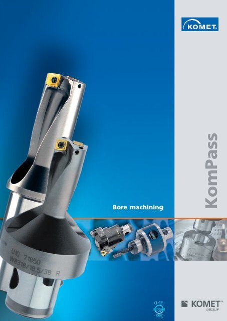
Bore machiningKomPass
With innovative solutions and tool designs for boremachining, the KOMET GROUP holds a leading market roleworldwide. Our developments for boring, tapping andreaming contribute enormously to our customers' success.KomPass – focussed on the demands of boremachiningThis KomPass catalogue opens up the whole world ofKOMET bore machining for you. Over more than 700 pages,in easy to view form, you will find the complete drillprogramme, the relevant adaptors and the appropriateextensive insert programme, divided according to materialsand machining tasks.The compendium is completed by technical descriptions,areas for use and machining and application examples.
Index1Chapter1Drilling22Roughing334567Fine BoringEasy Special TMAdaptorsKometric ®Inserts456789Technical NotesAccessories, Assembly parts:ABS ® , HSK, KomLoc ® clamping systemIndex of Order NumbersInternational Agencies89
DrillingPioneering drilling into the solidKUB ® insert drillsIn the 1970s with the development of the solid drill we enteredcompletely new territory. Since then the KUB ® family of solid drills hasdeveloped into a leading tool concept. By using highly efficient carbidesand the latest generation of coatings, the cutting edges are alwaysperfectly matched to the solid drilling operation.1.2
Drilling1PageProgramme summaryHelp table for tool selection1.4 – 1.51.6 – 1.7KUB Quatron ®KUB Trigon ®KUB ® DrillKUB Duon ®1.8 – 1.231.24 – 1.591.60 – 1.691.70 – 1.891.90 – 1.101KUB Centron ®KUB ® Drill V46 / V47KUB ® Drill head V464KUB ® Drill headFlat-bottoming tool1.1141.102 – 1.1051.106 – 1.1091.110 – 1.1111.112 – 1.113Trepannning toolPacket Drill1.1151.3
Programme summary – adaptorsAdaptorsAdaptorsTaper shanksDIN 69871 5.36 – 5.37JIS B 6339 5.44 – 5.45Extension5.82Taper shanksDIN 69871 5.38JIS B 6339 5.46Reducer5.81Spindle adaptor flange5.64 – 5.65Adjustment deviceABS-MV5.79HSK Adaptor5.10EccentricAdjusting Device5.80VDI Adaptor5.76Adaptor sleeveFWD Whistle Notch5.84 – 5.85Adaptor5.78Adaptor sleeveHWD Weldon5.86HSK EccentricAdjusting Device5.11Expanding chuck5.92 – 5.93EccentricAdjusting Device5.40Adaptoron request1.4
Programme summary – solid drilling1Drilling · Trepanning · Flat bottomingPage KUB Quatron ®KUB Trigon ®KUB ® DrillKUB Duon ®KUB Centron ®KUB ® V46/V47KUB ® V464KUB ®Flat-bottoming toolPacket drillEasy Special TMKUB Quatron ®KUB Trigon ®KUB Trigon ®KUB Duon ®Easy Special TM Ø 14-65 mmØ 14-44 mmØ 38,5-82 mmØ 17,3-44,2 mmØ 20-81 mmØ 82-155 mmØ 80-155 mmØ 37-64 mmØ 17,5-82 mmØ 14-44 mmØ 14-44 mmØ 12-44 mmØ 14-54 mmØ 17,3-36,2 mmØ 12-44 mm1.10 – 1.131.20 – 1.211.26 – 1.291.50 – 1.511.62 – 1.671.70 – 1.891.90 – 1.971.102 – 1.1051.106 – 1.1071.112 – 1.1131.115Chapter 41.14 – 1.171.221.32 – 1.371.40 – 1.471.54 – 1.591.70 – 1.89Chapter 4 KUB ® Drill head Ø 83-128 mm 1.110 – 1.111Larger sizes on requestTrepannning toolon requestØ 83-198 mm1.1141.5
Help table for tool selectionØmmL / Dsoliddrillingblindholeforge/casting skin,interfaceangled startand drillingout,interruptedcutMachiningconvex cross bore centering chamber stack platebore,drillingseamroughboringadjustable14,0 - 65,0 ±0,2 2 × D§§§§§§§§§$$14,0 - 65,0 ±0,2 3 × D§§§$§§§§§$$15,0 - 44,0 ±0,2 4 × D§&&&$12,0 - 44,0 ±0,1 2 × D§§§§§$$§$§12,0 - 54,0 ±0,1 3 × D§§§§$$$$&§14,0 - 44,0 ±0,1 4 × D§§$&&&&&$38,5 - 82,0 +1,0–0,5 3 × D§§&&&&&&&$45,0 - 82,0 ±0,22 × D§§§§§$$§$$45,0 - 82,0 ±0,23 × D§§§$$$$$$17,3 - 44,2 ±0,1 5 × D§§$&$$&§&20,0 - 81,0 ±0,1 9 × D§§$&&&&&82,0 - 155,0up to9 × D§§$&&&&&§80,0 - 155,0 6 × D§§$&&&&&§83,0 - 128,0 ±0,4 4 × D§§$&&&&&83,0 - 198,0 ±0,5 3 × D§$$$$§§37,0 - 64,0 ±0,5 3 × D$§§14,0 - 82,0 2 × D$$$&$$$$§&&14,0 - 82,0 3 × D$$$&$$$$§&&14,0 - 44,0 1,5-4 × D§§§$$$$$§1.6§ very good $ good & possible: see technical notes, chapter 8
1CoolantToolMaterialConnectionEmulsion MQLinternal external internal externalMild steel/tool steelStainless andacid-resistant steelGrey cast iron,spheroidal cast ironNon-ferrous metalsHeat-resistant steelsHardened tool steelP M K N S HrightleftABS Cylindrical VDI ABS VDIshank compatiblecompatible§$§$§§§§§§§§§§§§§§§§§§$$$$&&$&&&&$$&$§§§§§$$$§&&&$$$$$$& Easy Special TM Chapter 41.10 1.14$KUB Quatron ®$1.20 1.21$&KUB Trigon ®1.26 1.32 1.40 1.50 1.54&&KUB ® V82 / V83 / V841.62$&KUB ® V13 / V141.66&KUB Duon ®KUB Centron ®KUB ® V46 / V471.721.921.1021.72KUB ® Drill head V4641.106&KUB ® Drill head1.110&Trepannning tool1.114&KUB ®Flat-bottoming tool1.112&Packet drill1.115&1.7
KUB Quatron ®High performance drillnow up to Ø 65 mmHigh stability and economyby using square inserts.Free flow of chips and no wear onthe tool bodybecause of the special surface treatment.Can be used for difficult drillingconditionssuch as cast angles, rolling skin orinterrupted cut.Excellent bore qualitywith no withdrawal grooves.Maximum tool lifewith four cutting edges made up of specificsubstrates and coatings.Same insert internally and externallysame coating, same locking screw.Intermediate sizescan be supplied within 4 weekse.g. U10 71940 (Ø 19,4 mm 2×D).1.8
1KUB Quatron ® 1.21PageDrilling depth 2×D, 3×D · Ø 14 - 65 mmR.H. cuttingwith ABS ® connection1.10 – 1.13Drilling depth 4×D · Ø 15 - 44 mmR.H. cuttingwith ABS ® connection1.20Drilling depth 2×D, 3×D · Ø 14 - 44 mmR.H. cuttingwith cylindrical shank (combination shank)DIN 6535 HE (similar 1835 E) and 65951.14 – 1.17Drilling depth 4×D · Ø 17 - 29 mmR.H. cuttingwith cylindrical shank (combination shank)DIN 6535 HE (similar 1835 E) and 6595Technical notesAlternative inserts2×D, 3×D4×D1.18 – 1.191.22 – 1.231.9
KUB Quatron ® Ø 14 – 33 mmInsert drill with ABS ® connectionR.H. cuttingLNABS50D0,22×D3×DD* max.diameterwithoffset.ABSd Order No. N LOrder No. N L14,015,015,516,017,017,518,018,519,019,520,020,521,022,022,523,024,024,525,026,026,527,028,028,529,029,530,031,031,532,033,014,515,516,016,517,518,018,519,019,520,020,521,021,522,523,023,524,525,025,526,527,027,528,529,029,530,030,531,532,032,533,550505050505050505050505050505050505050505050505050505050505050U10 71402U10 71502U10 71550U10 71600U10 71700U10 71750U10 71800U10 71850U10 71900U10 71950U10 72000U10 72050U10 72100U10 72200U10 72250U10 72300U10 72400U10 72450U10 72500U10 72600U10 72650U10 72700U10 72800U10 72850U10 72900U10 72950U10 73000U10 73100U10 73150U10 73200U10 733002830323234363638384040424244464648505052545456585859606264646663656767697171737375757777798181838585878989919393951001021041041060,450,460,460,460,470,470,470,480,480,490,490,500,500,510,520,520,540,540,550,560,580,580,600,610,610,630,660,680,700,700,73U11 51402U11 51502U11 51550U11 51600U11 51700U11 51750U11 51800U11 51850U11 51900U11 51950U11 52000U11 52050U11 52100U11 52200U11 52250U11 52300U11 52400U11 52450U11 52500U11 52600U11 52650U11 52700U11 52800U11 52850U11 52900U11 52950U11 53000U11 53100U11 53150U11 53200U11 533004245484851545457576060636366696972757578818184878788,59093969699778083838689899292959598981011041041071101101131161161191221221251301331361361390,470,470,470,480,480,490,490,500,480,510,520,520,530,520,560,590,600,600,600,610,630,630,650,670,670,690,790,790,780,800,84For other diameters see following pageNote:Any intermediate dimensions from Ø 14 – 65 mm and inch dimensions are available on request.Supply includes:KUB Quatron ® drill with assembly parts. Please order insert and accessories separately.* Adjustment device see chapter 51.10EP 0 547 049 and other patents (ABS ® ) and patent applications (KUB Quatron ® )
1L / Dsolid drillingblind holeforge/castingskin, interfaceangled convex cross bore centering bore chamber stack platedrillingrough boringadjustable2×D3×D§§§§§§§$§§§§§§§§§§$$$$§ very good $ good & possible: see technical notes, chapter 8 X not possibleBasic recommendationInsertforworkpiece materialAssembly partsClamping screw StartingtorqueAccessoriesScrewdriverOrder No.size-01 -21ISO-CodepieceP M KN S HOrder No.ArticleNmOrder No.ArticleW83 13000.0184W83 13210.042730W83 13000.0161W83 13210.047710W83 13000.0179SOEX050204-01 BK84SOEX050204-21 BK2730SOEX050204-01 BK61SOEX050204-21 BK7710SOEX050204-01 BK792N00 56041S/M2×4,3-6IP0,62L05 008106IPW83 18000.0984W83 18210.062730W83 18000.0961W83 18210.067710W83 18000.0979SOEX060306-01 BK84SOEX060306-21 BK2730SOEX060306-01 BK61SOEX060306-21 BK7710SOEX060306-01 BK792N00 57553S/M2,2×5,5-6IP1,01L05 008106IPW83 23000.0184W83 23210.082730W83 23000.0161W83 23210.087710W83 23000.0179SOEX07T308-01 BK84SOEX07T308-21 BK2730SOEX07T308-01 BK61SOEX07T308-21 BK7710SOEX07T308-01 BK792N00 57571S/M2,5×6,3-8IP1,28L05 008308IPW83 32000.1584W83 32210.082730W83 32000.1561W83 32210.087710W83 32000.1579SOEX090408-01 BK84SOEX090408-21 BK2730SOEX090408-01 BK61SOEX090408-21 BK7710SOEX090408-01 BK792N00 57261S3575-15IP2,8L05 0086015IPTechnical Notes and alternative inserts: page 1.18 - 1.191.11
KUB Quatron ® Ø 34 – 65 mmInsert drill with ABS ® connectionR.H. cuttingLLNNABS50D0,2ABS63ABS80D0,22×D3×DD* max.diameterwithoffset.ABSdOrder No.NLOrder No.NL34,034,550U10 73400681080,75U11 534001021420,8535,035,550U10 73500701100,77U11 535001051450,8936,036,550U10 73600721120,80U11 536001081480,9337,037,550U10 73700741240,88U11 537001111611,0437,538,050U10 73750761260,90U11 537501141641,0238,038,550U10 73800761260,92U11 538001141641,0839,039,550U10 73900781280,95U11 539001171671,1339,540,050U10 73950801300,97U11 539501201701,1440,040,550U10 74000801300,98U11 540001201701,1741,041,550U10 74100821321,02U11 541001231731,2242,042,550U10 74200841341,06U11 542001261761,2743,043,550U10 74300861361,10U11 543001291791,3344,044,550U10 74400881381,14U11 544001321821,4145,045,563U10 84500901451,47U12 345001351901,7346,046,563U10 84600921471,51U12 346001381931,8047,047,563U10 84700941491,55U12 347001411961,8648,048,563U10 84800961511,60U12 348001441991,9349,049,563U10 84900981531,65U12 349001472022,0050,050,563U10 850001001551,70U12 350001502052,0851,051,563U10 851001021571,75U12 351001532082,1552,052,563U10 852001041591,81U12 352001562112,2453,053,563U10 853001061611,82U12 353001592142,2754,054,563U10 854001081631,88U12 354001622172,3555,055,580U10 955001101652,57U12 455001652203,0756,056,580U10 956001121672,64U12 456001682233,1657,057,580U10 957001141692,70U12 457001712263,2658,058,580U10 958001161712,76U12 458001742293,3559,059,580U10 959001181732,83U12 459001772323,4560,060,580U10 960001201752,93U12 460001802353,5961,061,580U10 961001221773,01U12 461001832383,6062,062,580U10 962001241793,08U12 462001862413,8163,063,580U10 963001261813,18U12 463001892443,9564,064,580U10 964001281833,26U12 464001922474,0765,065,580U10 965001301853,35U12 465001952504,20Note:Any intermediate dimensions from Ø 14 – 65 mm and inch dimensions are available on request.Supply includes:KUB Quatron ® drill with assembly parts. Please order insert and accessories separately.* Adjustment device see chapter 51.12EP 0 547 049 and other patents (ABS ® ) and patent applications (KUB Quatron ® )
1L / Dsolid drillingblind holeforge/castingskin, interfaceangled convex cross bore centering bore chamber stack platedrillingrough boringadjustable2×D3×D§§§§§§§$§§§§§§§§§§$$$$§ very good $ good & possible: see technical notes, chapter 8 X not possibleBasic recommendationInsertforworkpiece materialAssembly partsClamping screw StartingtorqueAccessoriesScrewdriverOrder No.size-01 -21ISO-CodepieceP M KN S HOrder No.ArticleNmOrder No.ArticleW83 44000.1884W83 44210.082730W83 44000.1861W83 44210.087710W83 44000.1879SOEX120508-01 BK84SOEX120508-21 BK2730SOEX120508-01 BK61SOEX120508-21 BK7710SOEX120508-01 BK792N00 57301S45100-20IP6,25L05 0087020IPW83 23000.0184W83 23210.082730W83 23000.0161W83 23210.087710W83 23000.0179SOEX07T308-01 BK84SOEX07T308-21 BK2730SOEX07T308-01 BK61SOEX07T308-21 BK7710SOEX07T308-01 BK794N00 57571S/M2,5×6,3-8IP1,28L05 008308IPW83 32000.1584W83 32210.082730W83 32000.1561W83 32210.087710W83 32000.1579SOEX090408-01 BK84SOEX090408-21 BK2730SOEX090408-01 BK61SOEX090408-21 BK7710SOEX090408-01 BK794N00 57261S3575-15IP2,8L05 0086015IPTechnical Notes and alternative inserts: page 1.18 - 1.191.13
KUB Quatron ® Ø 14 – 33 mmInsert drill with cylindrical shank (combination shank) DIN 6535 HE (similar 1835 E) and 6595R.H. cuttinglLNdD±0,22×D3×DD* max.diameterwithoffset.Cylindricalshankd × lOrder No.NLOrder No.NL14,015,015,516,017,017,518,018,519,019,520,020,521,022,022,523,024,024,525,026,026,527,028,028,529,029,530,031,031,532,033,014,515,516,016,517,518,018,519,019,520,020,521,021,522,523,023,524,024,525,526,527,027,528,529,029,530,030,531,532,032,533,520 × 5020 × 5020 × 5020 × 5020 × 5025 × 5625 × 5625 × 5625 × 5625 × 5625 × 5625 × 5625 × 5625 × 5625 × 5625 × 5632 × 6032 × 6032 × 6032 × 6032 × 6032 × 6032 × 6032 × 6032 × 6032 × 6032 × 6032 × 6032 × 6032 × 6032 × 6040 × 68U10 01402U10 01502U10 01550U10 01600U10 01700U10 11750U10 11800U10 11850U10 11900U10 11950U10 12000U10 12050U10 12100U10 12200U10 12250U10 12300U10 22400U10 22450U10 22500U10 22600U10 22650U10 22700U10 22800U10 22850U10 22900U10 22950U10 23000U10 23100U10 23150U10 23200U10 23300U10 33300283032323436363838404042424446464850505254545658585960626464666652545656586060626264646666687070727474767878808282848991939395950,170,180,180,190,190,270,270,270,280,290,290,300,300,310,310,320,510,520,520,540,550,560,570,580,590,600,630,650,660,670,731,02U11 61402U11 61502U11 61550U11 61600U11 61700U11 71750U11 71800U11 71850U11 71900U11 71950U11 72000U11 72050U11 72100U11 72200U11 72250U11 72300U11 82400U11 82450U11 82500U11 82600U11 82650U11 82700U11 82800U11 82850U11 82900U11 82950U11 83000U11 83100U11 83150U11 83200U11 83300U11 933004245484851545457576060636366696972757578818184878788,5909396969999666972727578788181848487879093939699991021051051081111111141191221251251281280,180,190,190,200,200,280,280,290,290,300,310,310,320,330,340,350,550,560,560,580,600,610,630,650,660,670,700,730,750,760,831,12For other diameters see following pageNote:Any intermediate dimensions from Ø 14 – 44 mm and inch dimensions are available on request.Supply includes:KUB Quatron ® drill with assembly parts. Please order insert and accessories separately.1.14Patented design (KUB Quatron ® )
1L / Dsolid drillingblind holeforge/castingskin, interfaceangled convex cross bore centering bore chamber stack platedrillingrough boringadjustable2×D3×D§§§§§§§$§§§§§§§§§§$$$$§ very good $ good & possible: see technical notes, chapter 8 X not possibleBasic recommendationInsertforworkpiece materialAssembly partsClamping screw StartingtorqueAccessoriesScrewdriverOrder No.size-01 -21ISO-CodepieceP M KN S HOrder No.ArticleNmOrder No.ArticleW83 13000.0184W83 13210.042730W83 13000.0161W83 13210.047710W83 13000.0179SOEX050204-01 BK84SOEX050204-21 BK2730SOEX050204-01 BK61SOEX050204-21 BK7710SOEX050204-01 BK792N00 56041S/M2×4,3-6IP0,62L05 008106IPW83 18000.0984W83 18210.062730W83 18000.0961W83 18210.067710W83 18000.0979SOEX060306-01 BK84SOEX060306-21 BK2730SOEX060306-01 BK61SOEX060306-21 BK7710SOEX060306-01 BK792N00 57553S/M2,2×5,5-6IP1,01L05 008106IPW83 23000.0184W83 23210.082730W83 23000.0161W83 23210.087710W83 23000.0179SOEX07T308-01 BK84SOEX07T308-21 BK2730SOEX07T308-01 BK61SOEX07T308-21 BK7710SOEX07T308-01 BK792N00 57571S/M2,5×6,3-8IP1,28L05 008308IPW83 32000.1584W83 32210.082730W83 32000.1561W83 32210.087710W83 32000.1579SOEX090408-01 BK84SOEX090408-21 BK2730SOEX090408-01 BK61SOEX090408-21 BK7710SOEX090408-01 BK792N00 57261S3575-15IP2,8L05 0086015IPTechnical Notes and alternative inserts: page 1.18 - 1.191.15
KUB Quatron ® Ø 34 – 44 mmInsert drill with cylindrical shank (combination shank) DIN 6535 HE (similar 1835 E) and 6595R.H. cuttinglLNdD±0,22×D3×DD* max.diameterwithoffset.Cylindricalshankd × lOrder No.NLOrder No.NL34,035,036,037,037,538,039,039,540,041,042,043,044,034,535,536,537,538,038,539,540,040,541,542,543,544,532 × 6032 × 6032 × 6032 × 6032 × 6032 × 6032 × 6032 × 6032 × 6032 × 6032 × 6032 × 6032 × 60U10 23400U10 23500U10 23600U10 23700U10 23750U10 23800U10 23900U10 23950U10 24000U10 24100U10 24200U10 24300U10 244006870727476767880808284868897991011131151151171191191211231251270,750,780,800,890,910,920,950,970,991,021,061,101,14U11 83400U11 83500U11 83600U11 83700U11 83750U11 83800U11 83900U11 83950U11 84000U11 84100U11 84200U11 84300U11 8440010210510811111411411712012012312612913240 × 6840 × 6840 × 6840 × 6840 × 6840 × 6840 × 6840 × 6840 × 6840 × 6840 × 6840 × 6840 × 68U10 33400U10 33500U10 33600U10 33700U10 33750U10 33800U10 33900U10 33950U10 34000U10 34100U10 34200U10 34300U10 344006870727476767880808284868897991011131151151171191191211231251271,041,071,091,181,201,211,241,261,281,311,351,391,43U11 93400U11 93500U11 93600U11 93700U11 93750U11 93800U11 93900U11 93950U11 94000U11 94100U11 94200U11 94300U11 94400102105108111114114117120120123126129132Note:Any intermediate dimensions from Ø 14 – 44 mm and inch dimensions are available on request.Supply includes:KUB Quatron ® drill with assembly parts. Please order insert and accessories separately.1311311341341371371501501531531531531561561591591591591621621651651681681711710,861,150,891,180,931,221,031,321,061,351,071,361,121,411,151,441,171,461,221,511,271,561,331,621,341,631.16Patented design (KUB Quatron ® )
1L / Dsolid drillingblind holeforge/castingskin, interfaceangled convex cross bore centering bore chamber stack platedrillingrough boringadjustable2×D3×D§§§§§§§$§§§§§§§§§§$$$$§ very good $ good & possible: see technical notes, chapter 8 X not possibleBasic recommendationInsertforworkpiece materialAssembly partsClamping screw StartingtorqueAccessoriesScrewdriverOrder No.size-01 -21ISO-CodepieceP M KN S HOrder No.ArticleNmOrder No.ArticleW83 44000.1884W83 44210.082730W83 44000.1861W83 44210.087710W83 44000.1879SOEX120508-01 BK84SOEX120508-21 BK2730SOEX120508-01 BK61SOEX120508-21 BK7710SOEX120508-01 BK792N00 57301S45100-20IP6,25L05 0087020IPTechnical Notes and alternative inserts: page 1.18 - 1.191.17
Technical NotesGuideline values for solid drilling with KUB Quatron ® Ø 14 – 65 mmMaterial groupStrength Rm (N/mm 2 )Hardness HBMaterialMaterial examplematerial code/DINCutting speedv cm/minØ 14-15,9Ø 16-17,5Ø 17,6-21,5Ø 21,6-272×D 3×DMax. feedf (mm/rev)Ø 28-33Ø 34-44Ø 45-54Ø 55-65Ø 14-15,9Ø 16-17,5Ø 17,6-21,5Max. feedf (mm/rev)Ø 21,6-27Ø 28-33Ø 34-44Ø 45-54Ø 55-654.0 3.0 2.1 2.0 1.0P>900 >900 60014001800250180250130230250200300901006075100special alloys:Inconel, Hastelloy,Nimonic, stc.titanium,titanium alloysstainless steelsstainless steelsstainless /fireproof steelsgray cast ironalloy gray castironInconel 718/2.4668,Nimonic 80A/2.4631TiAl5Sn2 / 3.7114X2CrNi189 / 1.4306,X5CrNiMo1810/1.4401X8CrNb17/1.4511,X10CrNiMoTi1810/1.4571X10CrAl7 / 1.4713,X8CrS-38-18/1.4862GG-25/0.6025,GG-35/0.6035GG-NiCr202 / 0.6660spheroidal, GGG-40 / 0.7040graphite cast iron,ferriticGGG-50 / 0.7050spheroidalgraphite cast iron, GGG-55 / 0.7055ferritic/perliticGTW-55 / 0.8055spheroidal graph. GGG-60 / 0.7060cast iron, perliticmalleable iron GTS-65 / 0.8165alloyed spheroidal GGG-NiCr20-2 /graphite cast iron 0.7661vermicular cast GGV Ti < 0,2ironGGV Ti > 0,2copper alloy, CuZn36Pb3 / 2.1182,brass,G-CuPb15Sn /lead-alloy bronze,lead bronze: 2.1182good cutcopper alloy,brass,bronze:average cutwroughtaluminium alloyscast alum. alloy:Si-content 10%hardened steels< 45 HRChardened steels> 45 HRCCuZn40Al1 / 2.0550,E-Cu57 / 2.0060AlMg1 / 3.3315,AlMnCu / 3.0517G-AlMg5 / 3.3561,G-AlSi9Mg / 3.2373G-AlSi10Mg / 3.2381608018016016020016018016014014012030040060030025080400,05 0,05 0,10 0,10 0,08 0,08 0,12 0,10 0,14 0,14 0,14 0,14 0,14 0,16 0,06 0,08 0,08 0,06 0,060,05 0,05 0,12 0,12 0,08 0,08 0,14 0,12 0,16 0,16 0,16 0,16 0,16 0,16 0,08 0,08 0,10 0,08 0,080,08 0,08 0,14 0,14 0,10 0,10 0,16 0,16 0,18 0,18 0,18 0,18 0,18 0,25 0,10 0,12 0,12 0,10 0,100,10 0,10 0,20 0,16 0,12 0,12 0,25 0,20 0,22 0,22 0,22 0,20 0,20 0,30 0,12 0,16 0,14 0,12 0,120,10 0,10 0,20 0,16 0,12 0,12 0,20 0,20 0,25 0,22 0,22 0,20 0,20 0,30 0,12 0,16 0,14 0,12 0,120,10 0,10 0,30 0,20 0,12 0,15 0,25 0,25 0,25 0,25 0,25 0,25 0,25 0,30 0,14 0,20 0,16 0,12 0,120,10 0,10 0,20 0,16 0,12 0,12 0,25 0,20 0,22 0,22 0,22 0,20 0,20 0,30 0,12 0,16 0,14 0,12 0,120,10 0,10 0,20 0,16 0,12 0,12 0,20 0,20 0,25 0,22 0,22 0,20 0,20 0,30 0,12 0,16 0,14 0,12 0,120,05 0,05 0,10 0,10 0,08 0,08 0,12 0,10 0,14 0,14 0,14 0,14 0,14 0,16 0,06 0,08 0,08 0,06 0,060,05 0,05 0,12 0,12 0,08 0,08 0,14 0,12 0,16 0,16 0,16 0,16 0,16 0,16 0,08 0,08 0,10 0,08 0,080,08 0,08 0,14 0,14 0,10 0,10 0,16 0,16 0,18 0,18 0,18 0,18 0,18 0,25 0,10 0,12 0,12 0,10 0,100,10 0,10 0,20 0,16 0,12 0,12 0,25 0,20 0,22 0,22 0,22 0,20 0,20 0,30 0,12 0,16 0,14 0,12 0,120,10 0,10 0,20 0,16 0,12 0,12 0,20 0,20 0,25 0,22 0,22 0,20 0,20 0,30 0,12 0,16 0,14 0,12 0,120,10 0,10 0,30 0,20 0,12 0,15 0,25 0,25 0,25 0,25 0,25 0,25 0,25 0,30 0,14 0,20 0,16 0,12 0,120,10 0,10 0,20 0,16 0,12 0,12 0,25 0,20 0,22 0,22 0,22 0,20 0,20 0,30 0,12 0,16 0,14 0,12 0,120,10 0,10 0,20 0,16 0,12 0,12 0,20 0,20 0,25 0,22 0,22 0,20 0,20 0,30 0,12 0,16 0,14 0,12 0,121.18Important: See chapter 8 for more application details and safety notes !
1Alternative Insertsfor better chip controlInsertforworkpiece material-13 -21D Order No.ISO-Code P M K N S HsizeW83 13000.0284 SOEX050204-13 BK84W83 13210.042730 SOEX050204-21 BK2730W83 13000.0279 SOEX050204-13 BK79W83 13210.047710 SOEX050204-21 BK7710W83 18000.1084 SOEX060306-13 BK84W83 18210.062730 SOEX060306-21 BK2730W83 18000.1079 SOEX060306-13 BK79W83 18210.067710 SOEX060306-21 BK7710W83 23000.0284 SOEX07T308-13 BK84W83 23210.082730 SOEX07T308-21 BK2730W83 23000.0279 SOEX07T308-13 BK79W83 23210.087710 SOEX07T308-21 BK7710W83 32000.1784 SOEX090408-13 BK84W83 32210.082730 SOEX090408-21 BK2730W83 32000.1779 SOEX090408-13 BK79W83 32210.087710 SOEX090408-21 BK7710W83 44000.1984 SOEX120508-13 BK84W83 44210.082730 SOEX120508-21 BK2730W83 44000.1979 SOEX120508-13 BK79W83 44210.087710 SOEX120508-21 BK771014,0-17,518,0-21,522,0-27,028,0-33,034,0-44,055,0-65,0 45,0-54,0 34,0-44,0 28,0-33,0 22,0-27,0 18,0-21,5 14,0-17,555,0-65,0 45,0-54,0W83 23000.0284 SOEX07T308-13 BK84W83 23210.082730 SOEX07T308-21 BK2730W83 23000.0279 SOEX07T308-13 BK79W83 23210.087710 SOEX07T308-21 BK7710W83 32000.1784 SOEX090408-13 BK84W83 32210.082730 SOEX090408-21 BK2730W83 32000.1779 SOEX090408-13 BK79W83 32210.087710 SOEX090408-21 BK7710D Order No.ISO-Code P M K N S HsizeW83 13000.0179W83 13000.0169W83 18000.0979W83 18000.0969W83 23000.0179W83 23000.0169W83 32000.1579W83 32000.1569W83 44000.1879W83 44000.1869W83 23000.0179W83 23000.0169W83 32000.1579W83 32000.1569for greater strengthInsertSOEX050204-01 BK79SOEX050204-01 BK69SOEX060306-01 BK79SOEX060306-01 BK69SOEX07T308-01 BK79SOEX07T308-01 BK69SOEX090408-01 BK79SOEX090408-01 BK69SOEX120508-01 BK79SOEX120508-01 BK69SOEX07T308-01 BK79SOEX07T308-01 BK69SOEX090408-01 BK79SOEX090408-01 BK69forworkpiece materialD Order No.ISO-Code P M K N S Hsize14,0-17,518,0-21,522,0-27,028,0-33,034,0-44,045,0-54,055,0-65,0for higher cutting speedInsertW83 13000.0169 SOEX050204-01 BK69W83 13000.0174 SOEX050204-01 BK74W83 13000.016115 SOEX050204-01 BK6115W83 18000.0969 SOEX060306-01 BK69W83 18000.0974 SOEX060306-01 BK74W83 18000.096115 SOEX060306-01 BK6115W83 23000.0169 SOEX07T308-01 BK69W83 23000.0174 SOEX07T308-01 BK74W83 23000.016115 SOEX07T308-01 BK6115W83 32000.1569 SOEX090408-01 BK69W83 32000.1574 SOEX090408-01 BK74W83 32000.156115 SOEX090408-01 BK6115W83 44000.1869 SOEX120508-01 BK69W83 44000.1874 SOEX120508-01 BK74W83 44000.186115 SOEX120508-01 BK6115W83 23000.0169 SOEX07T308-01 BK69W83 23000.0174 SOEX07T308-01 BK74W83 23000.016115 SOEX07T308-01 BK6115W83 32000.1569 SOEX090408-01 BK69W83 32000.1574 SOEX090408-01 BK74W83 32000.156115 SOEX090408-01 BK6115forworkpiece material1.19
KUB Quatron ® Ø 15 – 44 mmInsert drill with ABS ® connectionR.H. cuttingLNABS50D0,24×DBasic recommendationInsertforAssembly partsClampingworkpiece material screwAccessoriesScrewdriverD15,015,5ABSd5050Order No.U12 51500U12 51550N6064L95990,500,51-01 -21Order No. ISO-Code P M K N S HsizeW83 13000.0184 SOEX050204-01 BK84W83 13000.0179 SOEX050204-01 BK79W83 13000.0161 SOEX050204-01 BK61W83 13210.047710 SOEX050204-21 BK7710Order No.ArticleN00 56041S/M2×4,3-6IP0,62 NmOrder No.ArticleL05 008106IP16,017,017,518,018,519,019,520,020,521,022,022,523,024,024,525,026,026,527,028,028,529,050505050505050505050505050505050505050505050U12 51600U12 51700U12 51750U12 51800U12 51850U12 51900U12 51950U12 52000U12 52050U12 52100U12 52200U12 52250U12 52300U12 52400U12 52450U12 52500U12 52600U12 52650U12 52700U12 52800U12 52850U12 529006468727276768080848488929296100100104108108112116116991031071071111111151151191191231271271311351351391431431471511510,510,520,530,530,540,540,560,560,570,570,590,610,610,620,630,630,640,670,670,700,730,73W83 13000.0184 SOEX050204-01 BK84W83 13000.0179 SOEX050204-01 BK79W83 13000.0161 SOEX050204-01 BK61W83 13210.047710 SOEX050204-21 BK7710W83 18000.0984 SOEX060306-01 BK84W83 18000.0979 SOEX060306-01 BK79W83 18000.0961 SOEX060306-01 BK61W83 18210.067710 SOEX060306-21 BK7710W83 23000.0184 SOEX07T308-01 BK84W83 23000.0179 SOEX07T308-01 BK79W83 23000.0161 SOEX07T308-01 BK61W83 23210.087710 SOEX07T308-21 BK7710W83 32000.1584 SOEX090408-01 BK84W83 32000.1579 SOEX090408-01 BK79W83 32000.1561 SOEX090408-01 BK61W83 32210.087710 SOEX090408-21 BK7710N00 56041S/M2×4,3-6IP0,62 NmN00 57553S/M2,2×5,5-6IP1,01 NmN00 57571S/M2,5×6,3-8IP1,28 NmN00 57261S3575-15IP2,8 NmL05 008106IPL05 008106IPL05 008308IPL05 0086015IP1.20EP 0 547 049 and other patents (ABS ® ) and patent applications (KUB Quatron ® )
1L / Dsolid drillingblind holeforge/castingskin, interfaceangled convex cross bore centering bore chamber stack platedrillingrough boringadjustable4×D § & & & $ X X X X X X§ very good $ good & possible: see technical notes, chapter 8 X not possibleLNABS63D0,24×DBasic recommendationInsertforAssembly partsClampingworkpiece material screwAccessoriesScrewdriverD30,031,032,033,034,035,036,037,038,039,040,041,042,043,044,0ABSd636363636363636363636363636363Order No.U14 03000U14 03100U14 03200U14 03300U14 03400U14 03500U14 03600U14 03700U14 03800U14 03900U14 04000U14 04100U14 04200U14 04300U14 04400N120124128132136140144148152156160164168172176L1601641681721761801841982022062102142182222261,161,21,241,291,381,421,481,621,681,741,781,841,891,962,04-01 -21Order No. ISO-CodesizeW83 32000.1584 SOEX090408-01 BK84W83 32000.1579 SOEX090408-01 BK79W83 32000.1561 SOEX090408-01 BK61W83 32210.087710 SOEX090408-21 BK7710W83 44000.1884 SOEX120508-01 BK84W83 44000.1879 SOEX120508-01 BK79W83 44000.1861 SOEX120508-01 BK61W83 44210.087710 SOEX120508-21 BK7710P M K N S HOrder No.ArticleN00 57261S3575-15IP2,8 NmN00 57301S45100-20IP6,25 NmOrder No.ArticleL05 0086015IPL05 0087020IPNote:Any intermediate dimensions from Ø 15 – 44 mm and inch dimensions are available on request.Supply includes:KUB Quatron ® drill with assembly parts. Please order insert and accessories separately.Technical Notes and alternative inserts: page 1.231.21
KUB Quatron ® Ø 17 – 29 mmL / Dsolid drillingblind holeforge/castingskin, interfaceangled convex cross bore centering bore chamber stack platedrillingrough boringadjustable4×D § & & & $ X X X X X X§ very good $ good & possible: see technical notes, chapter 8 X not possibleInsert drill with cylindrical shank (combination shank) DIN 6535 HE (similar 1835 E) and 6595R.H. cuttinglLNdD±0,2DCylindricalshankd × lOrder No.4×DNLOrder No.sizeBasic recommendationInsertforAssembly partsClampingworkpiece material screw-01 -21ISO-CodeP M K N S HOrder No.ArticleAccessoriesScrewdriverOrder No.Article17,017,520×5025×56U12 61700U12 71750687292960,220,31W83 13000.0184 SOEX050204-01 BK84W83 13000.0179 SOEX050204-01 BK79W83 13000.0161 SOEX050204-01 BK61W83 13210.047710 SOEX050204-21 BK7710N00 56041S/M2×4,3-6IP0,62 NmL05 008106IP18,018,519,019,520,020,521,022,022,523,024,024,525,026,026,527,025×5625×5625×5625×5625×5625×5625×5625×5625×5625×5632×6032×6032×6032×6032×6032×60U12 71800U12 71850U12 71900U12 71950U12 72000U12 72050U12 72100U12 72200U12 72250U12 72300U12 82400U12 82450U12 82500U12 82600U12 82650U12 827007276768080848488929296100100104108108961001001041041081081121161161201241241281321320,310,330,330,350,350,360,360,380,400,400,500,560,560,580,610,61W83 18000.0984 SOEX060306-01 BK84W83 18000.0979 SOEX060306-01 BK79W83 18000.0961 SOEX060306-01 BK61W83 18210.067710 SOEX060306-21 BK7710W83 23000.0184 SOEX07T308-01 BK84W83 23000.0179 SOEX07T308-01 BK79W83 23000.0161 SOEX07T308-01 BK61W83 23210.087710 SOEX07T308-21 BK7710N00 57553S/M2,2×5,5-6IP1,01 NmN00 57571S/M2,5×6,3-8IP1,28 NmL05 008106IPL05 008308IP28,028,529,032×6032×6032×60U12 82800U12 82850U12 829001121161161361401400,640,670,67W83 32000.1584 SOEX090408-01 BK84W83 32000.1579 SOEX090408-01 BK79W83 32000.1561 SOEX090408-01 BK61W83 32210.087710 SOEX090408-21 BK7710N00 57261S3575-15IP2,8 NmL05 0086015IPNote:Any intermediate dimensions from Ø 17 – 29 mm and inch dimensions are available on request.Supply includes:KUB Quatron ® drill with assembly parts. Please order insert and accessories separately.1.22Technical Notes and alternative inserts: page 1.23
1Technical NotesGuideline values for solid drilling withKUB Quatron ® – 4 × DMaterial group1.02.0500500-9002.1P900>90015.0 14.0 13.1 13.0 12.1 12.0 10.2 10.1 10.0 9.1 9.0 8.1 8.0 7.0 6.1 6.0 5.1H NKM S1400>600 600>900 0,2copper alloy,brass,CuZn36Pb3 /lead-alloy bronze, 2.1182,lead bronze: G-CuPb15Sn /good cut2.1182copper alloy,brass,bronze:average cutwroughtaluminium alloyscast alum. alloy:Si-content 10%hardened steels< 45 HRChardened steels> 45 HRCCuZn40Al1 / 2.0550,E-Cu57 / 2.0060AlMg1 / 3.3315,AlMnCu / 3.0517G-AlMg5 / 3.3561,G-AlSi9Mg / 3.2373G-AlSi10Mg /3.2381Cutting speedv cm/min300 250 3002001808060801801601602001601801601401401203004006003002508040Max. feedf (mm/rev)Ø 15-15,9Ø 16-17,5Ø 17,6-21,5Ø 21,6-27Ø 28-33Ø 34-440,10 0,08 0,060,10 0,08 0,060,16 0,12 0,100,20 0,14 0,120,20 0,14 0,120,16 0,14 0,120,080,080,120,200,200,160,060,080,120,160,160,14––––––0,050,050,080,080,080,080,050,050,080,080,080,080,060,060,100,140,160,160,060,060,100,140,160,160,060,060,080,120,160,160,140,160,200,250,300,200,120,140,160,200,250,200,120,140,160,200,250,200,120,140,160,200,250,200,120,140,160,200,250,200,100,120,140,160,200,160,100,120,140,160,200,160,100,120,140,160,200,180,080,100,120,140,160,160,080,100,120,120,120,100,100,120,140,160,160,160,120,140,160,200,200,160,040,040,060,060,060,060,040,040,060,060,060,06Alternative Insertsfor better chip controlD Order No.ISO-Code P M K N S Hsize34,0-44,0 28,0-33,0 22,0-27,0 18,0-21,5 16,0-17,5 15-15,5W83 13210.042730 SOEX050204-21 BK2730 only external cuttingW83 13000.0284 SOEX050204-13 BK84W83 13210.042730 SOEX050204-21 BK2730 only external cuttingW83 13000.0284 SOEX050204-13 BK84W83 13000.0279 SOEX050204-13 BK79W83 18210.062730 SOEX060306-21 BK2730 only external cuttingW83 18000.1084W83 18000.1079SOEX060306-13 BK84SOEX060306-13 BK79W83 23210.082730 SOEX07T308-21 BK2730 only external cuttingW83 23000.0284 SOEX07T308-13 BK84W83 23000.0279 SOEX07T308-13 BK79W83 32210.082730 SOEX090408-21 BK2730 only external cuttingW83 32000.1784W83 32000.1779SOEX090408-13 BK84SOEX090408-13 BK79W83 44210.082730 SOEX120508-21 BK2730 only external cuttingW83 44000.1984 SOEX120508-13 BK84W83 44000.1979 SOEX120508-13 BK79for higher cutting speedD Order No.ISO-Code34,0-44,0 28,0-33,0 22,0-27,0 18,0-21,5 16,0-17,5 15-15,5for greater strengthD Order No.ISO-Code34-44 28-33 22-27 18-21,5 15-17,5W83 13000.0169 SOEX050204-01 BK69W83 13000.016115 SOEX050204-01 BK6115W83 13000.0169 SOEX050204-01 BK69W83 13000.0174 SOEX050204-01 BK74W83 13000.016115 SOEX050204-01 BK6115W83 18000.0969 SOEX060306-01 BK69W83 18000.0974 SOEX060306-01 BK74W83 18000.096115 SOEX060306-01 BK6115W83 23000.0169 SOEX07T308-01 BK69W83 23000.0174 SOEX07T308-01 BK74W83 23000.016115 SOEX07T308-01 BK6115W83 32000.1569 SOEX090408-01 BK69W83 32000.1574 SOEX090408-01 BK74W83 32000.156115 SOEX090408-01 BK6115W83 44000.1869 SOEX120508-01 BK69W83 44000.1874 SOEX120508-01 BK74W83 44000.186115 SOEX120508-01 BK6115W83 13000.0179W83 13000.0169SOEX050204-01 BK79SOEX050204-01 BK69W83 18000.0979 SOEX060306-01 BK79W83 18000.0969 SOEX060306-01 BK69W83 23000.0179 SOEX07T308-01 BK79W83 23000.0169 SOEX07T308-01 BK69W83 32000.1579 SOEX090408-01 BK79W83 32000.1569 SOEX090408-01 BK69W83 44000.1879 SOEX120508-01 BK79W83 44000.1869 SOEX120508-01 BK69Important: See chapter 8 for more application details and safety notes !1.23
KUB Trigon ®Flexibility in productionwith various geometries andcoatingsClose bore tolerancesup to H8Extremely good surface finishcan be achievedMachining to productiondimensionwithout separate fine machiningUniversal usesuitable for rotating and stationaryoperations1.24
1KUB Trigon ®Drilling depth 2×D, 3×D, 4×D · Ø 14 - 44 mmR.H. cuttingwith ABS ® connectionTechnical notesAlternative insertsPage1.26 – 1.291.301.31Drilling depth 2×D, 3×D, 4×D · Ø 12 - 44 mmR.H. cuttingwith cylindrical shank (combination shank)DIN 6535 HE (similar 1835 E) and 6595Technical notesAlternative insertsDrilling depth 3×D, 4×D · Ø 14 - 54 mmR.H. cuttingCylindrical shank with parallel clamping surfaceTechnical notesAlternative inserts1.32 – 1.371.381.391.40 – 1.471.481.49Drilling depth 2×D, 3×D · Ø 14 - 44 mmL.H. cuttingwith ABS ® connectionTechnical notesAlternative insertsanti-clockwise1.50 – 1.511.521.53Drilling depth 3×D · Ø 14 - 54 mmL.H. cuttingCylindrical shank with parallel clamping surfaceTechnical notesAlternative insertsanti-clockwise1.54 – 1.59Milling cartridge for KUB Trigon ® see chapter 61.25
KUB Trigon ® Ø 14 – 29,5 mmInsert drill with ABS ® connectionR.H. cuttingL15NABS50D±0,12×D3×D4×DD* max.diameterwithoffset.ABSd Order No. N LOrder No. N LOrder No. N L141515,5161717,51818,51919,520212222,5232424,5252626,5272828,52929,5151616,5171818,51919202021222323,5242525,5262828,5303131,53232,550505050505050505050505050505050505050505050505050V30 31402V30 31502V30 31550V30 31600V30 31700V30 31750V30 31800V30 31850V30 31900V30 31950V30 32000V30 32100V30 32200V30 32250V30 32300V30 32400V30 32450V30 32500V30 32600V30 32650V30 32700V30 32800V30 32850V30 32900V30 3295028303232343636383840404244464648505052545456585860636567676971717373757577798181838585878989919393950,460,460,460,470,470,480,480,480,480,480,500,510,520,530,530,550,550,620,640,570,580,590,600,610,62V30 71402V30 71502V30 71550V30 71600V30 71700V30 71750V30 71800V30 71850V30 71900V30 71950V30 72000V30 72100V30 72200V30 72250V30 72300V30 72400V30 72450V30 72500V30 72600V30 72650V30 72700V30 72800V30 72850V30 72900V30 72950424548485154545757606063666969727575788181848787907780838386898992929595981011041041071101101131161161191221221250,470,470,470,480,480,490,490,500,480,510,520,530,520,560,590,600,600,600,610,630,630,650,670,670,69V30 91402V30 91502V30 91550V30 91600V30 91700V30 91750V30 91800V30 91850V30 91900V30 91950V30 92000V30 92100V30 92200V30 92250V30 92300V30 92400V30 92450V30 92500V30 92600V30 92650V30 92700V30 92800V30 92850V30 92900V30 9295056606464687272767680808488929296100100104108108112116116120919599991031071071111111151151191231271271311351351391431431471511511550,470,480,480,490,500,500,510,520,520,520,540,560,580,550,600,620,640,630,660,670,720,700,730,750,76For other diameters see following pageNote:Any intermediate dimensions from Ø 14 – 44 mm and inch dimensions are available on request.Supply includes:KUB Trigon ® drill with assembly parts. Please order insert and accessories separately.* Adjustment device see chapter 51.26EP 0 547 049 and other patents (ABS ® ), EP 883 455 and other patents (KUB Trigon ® )
1L / Dsolid drillingblind holeforge/castingskin, interfaceangled convex cross bore centering bore chamber stack platedrillingrough boringadjustable2×D3×D4×D§§§§§§§§$§§&§$&$$&$$&§$&XXX$&X§§$§ very good $ good & possible: see technical notes, chapter 8 X not possibleBasic recommendationInsertforworkpiece materialAssembly partsClamping screw StartingtorqueAccessoriesScrewdriverOrder No.size-01 -11ISO-CodeP M KN S HOrder No.ArticleNmOrder No.ArticleW29 10010.0484W29 10010.047930W29 10010.0462W29 10110.0477WOEX030204-01 BK84WOEX030204-01 BK7930WOEX030204-01 BK62WOEX030204-11 BK77N00 56041S/M2×4,3-6IP0,62L05 008106IPW29 18010.0484W29 18010.047930W29 18010.0462W29 18110.0477WOEX040304-01 BK84WOEX040304-01 BK7930WOEX040304-01 BK62WOEX040304-11 BK77N00 57553S/M2,2×5,5-6IP1,01L05 008106IPW29 24010.0484W29 24010.047930W29 24010.0462W29 24110.0477WOEX05T304-01 BK84WOEX05T304-01 BK7930WOEX05T304-01 BK62WOEX05T304-11 BK77N00 57511S/M2,5×7,2-8IP1,28L05 008308IPTechnical Notes and alternative inserts: page 1.30 - 1.311.27
KUB Trigon ® Ø 30 – 44 mmInsert drill with ABS ® connectionR.H. cuttingL15NABS50D±0,12×D3×D4×DD* max.diameterwithoffset.ABSd Order No. N LOrder No. N LOrder No. N L303131,532333435363737,5383939,5404142434432,533,533,534343536374040,5414242,54344454545505050505050505050505050505050505050V30 33000V30 33100V30 33150V30 33200V30 33300V30 33400V30 33500V30 33600V30 33700V30 33750V30 33800V30 33900V30 33950V30 34000V30 34100V30 34200V30 34300V30 344006062646466687072747676788080828486881001021041041061081101121241261261281301301321341361380,740,690,700,710,820,780,770,790,890,900,920,950,960,981,101,101,101,13V30 73000V30 73100V30 73150V30 73200V30 73300V30 73400V30 73500V30 73600V30 73700V30 73750V30 73800V30 73900V30 73950V30 74000V30 74100V30 74200V30 74300V30 7440090939696991021051081111141141171201201231261291321301331361361391421451481611641641671701701731761791820,790,790,780,800,840,850,890,931,041,021,081,131,141,171,221,271,331,41V30 93000V30 93100V30 93150V30 93200V30 93300V30 93400V30 93500V30 93600V30 93700V30 93750V30 93800V30 93900V30 93950V30 94000V30 94100V30 94200V30 94300V30 944001201241281281321361401441481521521561601601641681721761601641681681721761801841982022022062102102142182222260,820,860,880,910,940,971,011,061,181,191,221,291,321,361,431,501,521,66Note:Any intermediate dimensions from Ø 14 – 44 mm and inch dimensions are available on request.Supply includes:KUB Trigon ® drill with assembly parts. Please order insert and accessories separately.* Adjustment device see chapter 51.28EP 0 547 049 and other patents (ABS ® ), EP 883 455 and other patents (KUB Trigon ® )
1L / Dsolid drillingblind holeforge/castingskin, interfaceangled convex cross bore centering bore chamber stack platedrillingrough boringadjustable2×D3×D4×D§§§§§§§§$§§&§$&$$&$$&§$&XXX$&X§§$§ very good $ good & possible: see technical notes, chapter 8 X not possibleBasic recommendationInsertforworkpiece materialAssembly partsClamping screw StartingtorqueAccessoriesScrewdriverOrder No.size-01 -11ISO-CodeP M KN S HOrder No.ArticleNmOrder No.ArticleW29 24010.0484W29 24010.047930W29 24010.0462W29 24110.0477WOEX05T304-01 BK84WOEX05T304-01 BK7930WOEX05T304-01 BK62WOEX05T304-11 BK77N00 57511S/M2,5×7,2-8IP1,28L05 008308IPW29 34010.0484W29 34010.047930W29 34010.0462W29 34110.0477WOEX06T304-01 BK84WOEX06T304-01 BK7930WOEX06T304-01 BK62WOEX06T304-11 BK77N00 57521S/M3,5×7,3-10IP2,8L05 0085010IPTechnical Notes and alternative inserts: page 1.30 - 1.311.29
Technical NotesGuideline values for solid drilling with KUB Trigon ® Ø 14 – 44 mmwith ABS ® connection · R.H. cutting2×D 3×DMaterial groupStrength Rm N/mm 2Hardness HBMaterialMaterial examplematerial code/DINCutting speedv cm/minMax. feedf (mm/rev)Ø 14-16,9Ø 17-19,9Ø 20-24,9Ø 25-29,9Ø 30-36,9Ø 37-40,9Ø 41-44,0Ø 14-16,9Max. feedf (mm/rev)Ø 17-19,9Ø 20-24,9Ø 25-29,9Ø 30-36,9Ø 37-40,9Ø 41-44,0Ø 14-16,9Ø 17-19,94×DMax. feedf (mm/rev)Ø 20-24,9Ø 25-29,9Ø 30-36,9Ø 37-40,9Ø 41-44,03.0 2.1 2.0 1.0P>900 900high alloy steelsX6CrMo4 / 1.2341,X165CrMoV12/1.26011800,060,080,100,120,120,120,140,060,080,100,120,120,120,140,040,060,080,100,100,100,124.1HSS800,040,060,080,10–––0,040,060,080,10–––0,020,040,060,08–––16.0 15.0 14.0 13.1 13.0 12.1 12.0 10.2 10.1 10.0 9.1 9.0 8.1 8.0 7.0 6.1 6.0 5.1 5.0H NKM S400600900600>60014001800250180250130230250200300901006075100special alloys:Inconel, Hastelloy,Nimonic, stc.titanium,titanium alloysstainless steelsstainless steelsstainless /fireproof steelsgray cast ironalloy gray castironInconel 718/2.4668,Nimonic 80A/2.4631TiAl5Sn2 / 3.7114X2CrNi189 / 1.4306,X5CrNiMo1810/1.4401X8CrNb17/1.4511,X10CrNiMoTi1810/1.4571X10CrAl7 / 1.4713,X8CrS-38-18/1.4862GG-25/0.6025,GG-35/0.6035GG-NiCr202 /0.6660spheroidal,graphite cast iron, GGG-40 / 0.7040ferriticspheroidal GGG-50 / 0.7050graphite cast iron, GGG-55 / 0.7055ferritic/perlitic GTW-55 / 0.8055spheroidal graph.cast iron, perliticmalleable ironGGG-60 / 0.7060GTS-65 / 0.8165alloyed spheroidal GGG-NiCr20-2 /graphite cast iron 0.7661vermicular castironGGV Ti < 0,2GGV Ti > 0,2copper alloy,brass,CuZn36Pb3 /lead-alloy bronze, 2.1182,lead bronze: G-CuPb15Sn /good cut2.1182copper alloy,brass,bronze:average cutwroughtaluminium alloyscast alum. alloy:Si-content 10%hardened steels< 45 HRChardened steels> 45 HRCCuZn40Al1 / 2.0550,E-Cu57 / 2.0060AlMg1 / 3.3315,AlMnCu / 3.0517G-AlMg5 / 3.3561,G-AlSi9Mg / 3.2373G-AlSi10Mg /3.2381608018016016020016018016014014012030040060030025080400,05 0,05 0,10 0,10 0,05 0,05 0,05 0,08 0,08 0,10 0,08 0,08 0,08 0,10 0,06 0,06 0,06 0,06 0,040,08 0,05 0,12 0,12 0,08 0,08 0,08 0,10 0,10 0,12 0,10 0,10 0,08 0,12 0,06 0,06 0,08 0,08 0,060,08 0,08 0,14 0,14 0,08 0,08 0,12 0,14 0,14 0,16 0,14 0,14 0,10 0,14 0,08 0,08 0,10 0,10 0,080,10 0,10 0,20 0,18 0,10 0,10 0,16 0,16 0,20 0,25 0,20 0,20 0,14 0,20 0,12 0,12 0,14 0,12 0,100,10 0,10 0,20 0,18 0,10 0,10 0,16 0,16 0,20 0,16 0,20 0,20 0,14 0,20 0,12 0,12 0,14 0,10 0,100,10 0,12 0,20 0,20 0,12 0,10 0,18 0,16 0,20 0,18 0,20 0,20 0,16 0,20 0,12 0,12 0,14 0,12 0,100,10 0,12 0,25 0,20 0,12 0,12 0,20 0,20 0,25 0,18 0,25 0,25 0,18 0,25 0,12 0,14 0,14 0,12 0,100,05 0,05 0,10 0,10 0,05 0,05 0,05 0,08 0,08 0,10 0,08 0,08 0,08 0,10 0,06 0,06 0,06 0,06 0,040,08 0,05 0,12 0,12 0,08 0,08 0,08 0,10 0,10 0,12 0,10 0,10 0,08 0,12 0,06 0,06 0,08 0,08 0,060,08 0,08 0,14 0,14 0,08 0,08 0,12 0,14 0,14 0,16 0,14 0,14 0,10 0,14 0,08 0,08 0,10 0,10 0,080,10 0,10 0,20 0,18 0,10 0,10 0,16 0,16 0,20 0,25 0,20 0,20 0,14 0,20 0,12 0,12 0,14 0,12 0,100,10 0,10 0,20 0,18 0,10 0,10 0,16 0,16 0,20 0,25 0,20 0,20 0,14 0,20 0,12 0,12 0,14 0,10 0,100,10 0,12 0,20 0,20 0,12 0,10 0,18 0,16 0,20 0,25 0,20 0,20 0,16 0,20 0,12 0,12 0,14 0,12 0,100,10 0,12 0,25 0,20 0,12 0,12 0,20 0,20 0,25 0,25 0,25 0,25 0,18 0,25 0,12 0,14 0,14 0,12 0,100,03 0,03 0,08 0,08 0,03 0,03 0,03 0,06 0,06 0,08 0,06 0,06 0,06 0,08 0,04 0,04 0,04 0,04 0,020,06 0,03 0,10 0,10 0,06 0,06 0,06 0,08 0,08 0,10 0,08 0,08 0,06 0,10 0,04 0,04 0,06 0,06 0,040,06 0,06 0,12 0,12 0,06 0,06 0,10 0,12 0,12 0,14 0,12 0,12 0,08 0,12 0,06 0,06 0,08 0,08 0,060,08 0,08 0,18 0,16 0,08 0,08 0,14 0,14 0,18 0,23 0,18 0,18 0,12 0,18 0,10 0,10 0,12 0,10 0,080,08 0,08 0,18 0,16 0,08 0,08 0,14 0,14 0,18 0,23 0,18 0,18 0,12 0,18 0,10 0,10 0,12 0,08 0,080,08 0,10 0,18 0,18 0,10 0,08 0,16 0,14 0,18 0,23 0,18 0,18 0,14 0,18 0,10 0,10 0,12 0,10 0,080,08 0,10 0,23 0,18 0,10 0,10 0,18 0,18 0,23 0,23 0,23 0,23 0,16 0,23 0,10 0,12 0,12 0,10 0,081.30Important: See chapter 8 for more application details and safety notes !
1Alternative Insertsfor better chip controlInsertforworkpiece material-03 -13D Order No.ISO-Code P M K N S Hsizefor higher cutting speedInsertforworkpiece material-01 -11D Order No.ISO-Code P M K N S Hsize14,0-19,5W29 10130.0484W29 10130.0479WOEX030204-13 BK84WOEX030204-13 BK7914,0-19,5W29 10010.0472W29 10110.0450WOEX030204-01 BK72WOEX030204-11 BK5020,0-24,5W29 18130.0484W29 18130.0479WOEX040304-13 BK84WOEX040304-13 BK7920,0-24,5W29 18010.0472W29 18110.0450WOEX040304-01 BK72WOEX040304-11 BK5025,0-36,0W29 24130.0484 WOEX05T304-13 BK84W29 24130.0479 WOEX05T304-13 BK79W29 24030.046425 WOEX05T304-03 BK642525,0-36,0W29 24010.0472W29 24110.0450WOEX05T304-01 BK72WOEX05T304-11 BK5037,0-44,0W29 34130.0484 WOEX06T304-13 BK84W29 34130.0479 WOEX06T304-13 BK79W29 34030.046425 WOEX06T304-03 BK642537,0-44,0W29 34010.0472W29 34110.0450WOEX06T304-01 BK72WOEX06T304-11 BK50for greater strengthInsertforworkpiece material-01 -11D Order No.ISO-Code P M K N S Hsize14,0-19,5W29 10010.047930 WOEX030204-01BK7930W29 10010.0404 WOEX030204-01 P40W29 10010.0421 WOEX030204-01 K10W29 10110.0421 WOEX030204-11 K1020,0-24,5W29 18010.047930 WOEX040304-01BK7930W29 18010.0404 WOEX040304-01 P40W29 18010.0421 WOEX040304-01 K10W29 18110.0421 WOEX040304-11 K1025,0-36,0W29 24010.047930 WOEX05T304-01BK7930W29 24010.0404 WOEX05T304-01 P40W29 24010.0421 WOEX05T304-01 K10W29 24110.0421 WOEX05T304-11 K1037,0-44,0W29 34010.047930 WOEX06T304-01BK7930W29 34010.0404 WOEX06T304-01 P40W29 34010.0421 WOEX06T304-01 K10W29 34110.0421 WOEX06T304-11 K101.31
KUB Trigon ® Ø 12 – 19,5 mmInsert drill with cylindrical shank (combination shank) DIN 6535 HE (similar 1835 E) and 6595R.H. cuttinglLNdD±0,12×D3×D4×DD* max.diameter Cylindricalwith shankoffset. d × l Order No. N LOrder No. N LOrder No.NL12,012,713,013,714,015,015,516,017,017,518,018,519,019,51313,71414,7151616,5171818,5191919,52020 × 5020 × 5020 × 5020 × 5020 × 5025 × 5620 × 5025 × 5620 × 5025 × 5620 × 5025 × 5620 × 5025 × 5620 × 5025 × 5620 × 5025 × 5620 × 5025 × 5620 × 5025 × 5620 × 5025 × 56V43 31201V43 31271V43 31301V43 31371V43 31403–V43 31503–V43 31551–V43 31601–V43 31701–V43 31751–V43 31801–V43 31851–V43 31901–V43 31951–242626282830323234363638384048505052525456565860606262640,170,170,170,170,170,180,180,190,190,200,200,200,200,21V43 71201V43 71271V43 71301V43 71371V43 71403V44 71403V43 71503V44 71503V43 71551V44 71551V43 71601V44 71601V43 71701V44 71701V43 71751V44 71751V43 71801V44 71801V43 71851V44 71851V43 71901V44 71901V43 71951V44 719513639394242424545484848485151545454545757575760606063636666666969727272727575787878788181818184840,170,170,180,180,200,240,200,280,200,280,200,280,200,290,210,290,210,290,220,310,220,310,230,34––––V43 91403–V43 91503–––V43 91601–V43 91701–––V43 91801–––V43 91901–––56606468727680848892961000,220,200,190,210,270,28For other diameters see following pageNote:Any intermediate dimensions from Ø 14 – 44 mm and inch dimensions are available on request.Supply includes:KUB Trigon ® drill with assembly parts. Please order insert and accessories separately.1.32EP 883 455 and other patents (KUB Trigon ® )
1L / Dsolid drillingblind holeforge/castingskin, interfaceangled convex cross bore centering bore chamber stack platedrillingrough boringadjustable2×D3×D4×D§§§§§§§§$§§&§$&$$&$$&§$&XXX$&X§§$§ very good $ good & possible: see technical notes, chapter 8 X not possibleBasic recommendationInsertforworkpiece materialAssembly partsClamping screw StartingtorqueAccessoriesScrewdriverOrder No.size-01 -11ISO-CodeP M KN S HOrder No.ArticleNmOrder No.ArticleW29 04010.0284W29 04010.0279WOEX020102-01 BK84WOEX020102-01 BK79N00 56051S/M1,8×3,8-5IP0,38L05 008005IPW29 10010.0484W29 10010.047930W29 10010.0462W29 10110.0477WOEX030204-01 BK84WOEX030204-01 BK7930WOEX030204-01 BK62WOEX030204-11 BK77N00 56041S/M2×4,3-6IP0,62L05 008106IPTechnical Notes and alternative inserts: page 1.38 - 1.391.33
KUB Trigon ® Ø 20 – 29,5 mmInsert drill with cylindrical shank (combination shank) DIN 6535 HE (similar 1835 E) and 6595R.H. cuttinglLNdD±0,12×D3×D4×DD* max.diameter Cylindricalwith shankoffset. d × l Order No. N LOrder No. N LOrder No.NL20 × 50 V43 32001 40 64 0,25 V43 72001 60 84 0,23 –20,0 21 25 × 5632 × 60V44 32001–40 64 0,30 V44 72001V45 72001606084840,320,51V44 92001–20 × 50 V43 32101 42 66 0,22 V43 72101 63 87 0,20 –21,0 22 25 × 5632 × 60V44 32101–42 66 0,31 V44 72101V45 72101636387870,330,55V44 92101–20 × 50 V43 32201 44 68 0,22 V43 72201 66 90 0,26 –22,0 23 25 × 5632 × 60V44 32201–44 68 0,32 V44 72201V45 72201666690900,350,54V44 92201–20 × 50 V43 32251 46 70 0,24 V43 72251 69 93 0,23 –22,5 23,5 25 × 5632 × 60V44 32251–46 70 0,32 V44 72251V45 72251696993930,360,56––20 × 50 V43 32301 46 70 0,24 V43 72301 69 93 0,28 –23,0 24 25 × 5632 × 60V44 32301–46 70 0,33 V44 72301V45 72301696993930,360,56V44 92301–20 × 50 V43 32401 48 72 0,25 V43 72401 72 96 0,30 –24,0 25 25 × 5632 × 60V44 32401V45 32401484872720,340,57V44 72401V45 72401727296960,380,57V44 92401–20 × 50 V43 32451 50 74 0,26 V43 72451 75 99 0,31 –24,5 25,5 25 × 5632 × 60V44 32451V45 32451505074740,350,54V44 72451V45 72451757599990,400,58V44 92451–25,026,026,527,028,028,529,029,5262828,5303131,53232,525 × 5625 × 5625 × 5625 × 5625 × 5625 × 5625 × 5625 × 56V44 32501V44 32601V44 32651V44 32701V44 32801V44 32851V44 32901V44 32951505254545658586074767878808282840,350,370,370,400,400,400,410,42V44 72501V44 72601V44 72651V44 72701V44 72801V44 72851V44 72901V44 729517578818184878790991021051051081111111140,400,440,430,440,450,470,480,49––––––––32 × 6032 × 6032 × 6032 × 6032 × 6032 × 6032 × 6032 × 60V45 32501V45 32601V45 32651V45 32701V45 32801V45 32851V45 32901V45 32951505254545658586074767878808282840,550,560,570,570,590,590,600,61V45 72501V45 72601V45 72651V45 72701V45 72801V45 72851V45 72901V45 729517578818184878790991021051051081111111140,590,610,620,620,650,660,680,69V45 92501V45 92601–V45 92701V45 92801–V45 92901–For other diameters see following pageNote: Any intermediate dimensions from Ø 14 – 44 mm and inch dimensions are available on request.80848892961001001041081121161041081121161201241241281321361400,340,360,380,400,450,430,630,650,680,710,741.34EP 883 455 and other patents (KUB Trigon ® )
1L / Dsolid drillingblind holeforge/castingskin, interfaceangled convex cross bore centering bore chamber stack platedrillingrough boringadjustable2×D3×D4×D§§§§§§§§$§§&§$&$$&$$&§$&XXX$&X§§$§ very good $ good & possible: see technical notes, chapter 8 X not possibleBasic recommendationInsertforworkpiece materialAssembly partsClamping screw StartingtorqueAccessoriesScrewdriverOrder No.size-01 -11ISO-CodeP M KN S HOrder No.ArticleNmOrder No.ArticleW29 18010.0484W29 18010.047930W29 18010.0462W29 18110.0477WOEX040304-01 BK84WOEX040304-01 BK7930WOEX040304-01 BK62WOEX040304-11 BK77N00 57553S/M2,2×5,5-6IP1,01L05 008106IPW29 24010.0484W29 24010.047930W29 24010.0462W29 24110.0477WOEX05T304-01 BK84WOEX05T304-01 BK7930WOEX05T304-01 BK62WOEX05T304-11 BK77N00 57511S/M2,5×7,2-8IP1,28L05 008308IPSupply includes:KUB Trigon ® drill with assembly parts. Please order insert and accessories separately.Technical Notes and alternative inserts: page 1.38 - 1.391.35
KUB Trigon ® Ø 30,0 – 44,0 mmInsert drill with cylindrical shank (combination shank) DIN 6535 HE (similar 1835 E) and 6595R.H. cuttinglLNdD±0,12×D3×D4×DD* max.diameter Cylindricalwith shankoffset. d × l Order No. N LOrder No. N LOrder No.NL30,031,031,532,033,034,035,036,037,037,538,039,039,540,041,042,043,044,032,533,533,534343536374040,5414242,5434445454532 × 6032 × 6032 × 6032 × 6032 × 6032 × 6032 × 6032 × 6032 × 6032 × 6032 × 6032 × 6032 × 6032 × 6032 × 6032 × 6032 × 6032 × 60V45 33001V45 33101V45 33151V45 33201V45 33301V45 33401V45 33501V45 33601V45 33701V45 33751V45 33801V45 33901V45 33951V45 34001V45 34101V45 34201V45 34301V45 34401606264646668707274767678808082848688899193939597991011131151151171191191211231251270,650,670,680,690,710,730,750,780,850,860,870,900,920,940,981,041,101,13V45 73001V45 73101V45 73151V45 73201V45 73301V45 73401V45 73501V45 73601V45 73701V45 73751V45 73801V45 73901V45 73951V45 74001V45 74101V45 74201V45 74301V45 7440190939696991021051081111141141171201201231261291321191221251251281311341371501531531561591591621651681710,720,760,770,780,820,840,870,911,001,011,041,091,101,121,201,251,321,39V45 93001V45 93101–V45 93201V45 93301V45 93401V45 93501V45 93601––––––––––1201241281321361401441491531571611651691730,810,840,870,930,950,991,05Note:Any intermediate dimensions from Ø 14 – 44 mm and inch dimensions are available on request.Supply includes:KUB Trigon ® drill with assembly parts. Please order insert and accessories separately.1.36EP 883 455 and other patents (KUB Trigon ® )
1L / Dsolid drillingblind holeforge/castingskin, interfaceangled convex cross bore centering bore chamber stack platedrillingrough boringadjustable2×D3×D4×D§§§§§§§§$§§&§$&$$&$$&§$&XXX$&X§§$§ very good $ good & possible: see technical notes, chapter 8 X not possibleBasic recommendationInsertforworkpiece materialAssembly partsClamping screw StartingtorqueAccessoriesScrewdriverOrder No.size-01 -11ISO-CodeP M KN S HOrder No.ArticleNmOrder No.ArticleW29 24010.0484W29 24010.047930W29 24010.0462W29 24110.0477WOEX05T304-01 BK84WOEX05T304-01 BK7930WOEX05T304-01 BK62WOEX05T304-11 BK77N00 57511S/M2,5×7,2-8IP1,28L05 008308IPW29 34010.0484W29 34010.047930W29 34010.0462W29 34110.0477WOEX06T304-01 BK84WOEX06T304-01 BK7930WOEX06T304-01 BK62WOEX06T304-11 BK77N00 57521S/M3,5×7,3-10IP2,8L05 0085010IPTechnical Notes and alternative inserts: page 1.38 - 1.391.37
Technical NotesGuideline values for solid drilling with KUB Trigon ® Ø 12 – 44 mmwith cylindrical shank (combination shank) DIN 6535 HE (similar 1835 E) and 6595 · R.H. cutting2×D 3×D4×DMax. feedMax. feedMax. feedf (mm/rev)f (mm/rev)f (mm/rev)Material groupStrength Rm N/mm 2Hardness HBMaterialMaterial examplematerial code/DINCutting speedv cm/minØ 12-13,9Ø 14-16,9Ø 17-19,9Ø 20-24,9Ø 25-29,9Ø 30-36,9Ø 37-40,9Ø 41-44Ø 12-13,9Ø 14-16,9Ø 17-19,9Ø 20-24,9Ø 25-29,9Ø 30-36,9Ø 37-40,9Ø 41-44Ø 14-16,9Ø 17-19,9Ø 20-24,9Ø 25-29,9Ø 30-362.1 2.0 1.0P900non alloy /low alloy steels:heat resostantstructural, heattreated, nitride andtools steels42CrMo4 / 1.7225,CK60 / 1.12212000,050,060,080,100,140,160,160,160,050,060,080,100,140,160,160,160,040,060,080,120,144.0>900high alloy steelsX6CrMo4 / 1.2341,X165CrMoV12/1.26011800,030,050,080,100,120,120,120,140,030,050,080,100,100,120,120,140,040,060,080,100,114.1HSS800,020,040,060,080,100,100,120,120,020,040,060,080,100,100,120,120,030,050,070,080,0916.0 15.0 14.0 13.1 13.0 12.1 12.0 10.2 10.1 10.0 9.1 9.0 8.1 8.0 7.0 6.1 6.0 5.1 5.0H NKM S400600900600>60014001800250180250130230250200300901006075100special alloys:Inconel, Hastelloy,Nimonic, stc.titanium,titanium alloysstainless steelsstainless steelsstainless /fireproof steelsgray cast ironalloy gray castironInconel 718/2.4668,Nimonic 80A/2.4631TiAl5Sn2 / 3.7114X2CrNi189 / 1.4306,X5CrNiMo1810/1.4401X8CrNb17/1.4511,X10CrNiMoTi1810/1.4571X10CrAl7 / 1.4713,X8CrS-38-18/1.4862GG-25/0.6025,GG-35/0.6035GG-NiCr202 /0.6660spheroidal,graphite cast iron, GGG-40 / 0.7040ferriticspheroidal GGG-50 / 0.7050graphite cast iron, GGG-55 / 0.7055ferritic/perlitic GTW-55 / 0.8055spheroidal graph.cast iron, perliticmalleable ironGGG-60 / 0.7060GTS-65 / 0.8165alloyed spheroidal GGG-NiCr20-2 /graphite cast iron 0.7661vermicular castironGGV Ti < 0,2GGV Ti > 0,2copper alloy,brass,CuZn36Pb3 /lead-alloy bronze, 2.1182,lead bronze: G-CuPb15Sn /good cut2.1182copper alloy,brass,bronze:average cutwroughtaluminium alloyscast alum. alloy:Si-content 10%hardened steels< 45 HRChardened steels> 45 HRCCuZn40Al1 / 2.0550,E-Cu57 / 2.0060AlMg1 / 3.3315,AlMnCu / 3.0517G-AlMg5 / 3.3561,G-AlSi9Mg / 3.2373G-AlSi10Mg /3.238160801801601602001601801601401401203004006003002508040– – 0,05 0,08 0,03 0,03 0,05 0,05 0,03 0,05 0,05 0,06 0,08 0,10 0,05 0,05 0,03 0,02 0,020,05 0,05 0,10 0,10 0,05 0,05 0,05 0,08 0,08 0,10 0,08 0,08 0,08 0,10 0,06 0,06 0,06 0,06 0,040,08 0,05 0,12 0,12 0,08 0,08 0,08 0,10 0,10 0,12 0,10 0,10 0,08 0,12 0,06 0,06 0,08 0,08 0,060,08 0,08 0,14 0,14 0,08 0,08 0,12 0,14 0,14 0,16 0,14 0,14 0,10 0,14 0,08 0,08 0,10 0,10 0,080,10 0,10 0,20 0,18 0,10 0,10 0,16 0,16 0,20 0,25 0,20 0,20 0,14 0,20 0,12 0,12 0,14 0,12 0,100,10 0,10 0,20 0,18 0,10 0,10 0,16 0,16 0,20 0,25 0,20 0,20 0,14 0,20 0,12 0,12 0,14 0,10 0,100,10 0,12 0,20 0,20 0,12 0,10 0,18 0,16 0,20 0,25 0,20 0,20 0,16 0,20 0,12 0,12 0,14 0,12 0,100,10 0,12 0,25 0,20 0,12 0,12 0,20 0,20 0,25 0,25 0,25 0,25 0,18 0,25 0,12 0,14 0,14 0,12 0,10– – 0,05 0,08 0,03 0,03 0,05 0,05 0,03 0,05 0,05 0,06 0,08 0,10 0,05 0,05 0,03 0,02 0,020,05 0,05 0,10 0,10 0,05 0,05 0,05 0,08 0,08 0,10 0,08 0,08 0,08 0,10 0,06 0,06 0,06 0,06 0,040,08 0,05 0,12 0,12 0,08 0,08 0,08 0,10 0,10 0,12 0,10 0,10 0,08 0,12 0,06 0,06 0,08 0,08 0,060,08 0,08 0,14 0,14 0,08 0,08 0,12 0,14 0,14 0,16 0,14 0,14 0,10 0,14 0,08 0,08 0,10 0,10 0,080,10 0,10 0,20 0,18 0,10 0,10 0,16 0,16 0,20 0,25 0,20 0,20 0,14 0,20 0,12 0,12 0,14 0,12 0,100,10 0,10 0,20 0,18 0,10 0,10 0,16 0,16 0,20 0,25 0,20 0,20 0,14 0,20 0,12 0,12 0,14 0,10 0,100,10 0,12 0,20 0,20 0,12 0,10 0,18 0,16 0,20 0,25 0,20 0,20 0,16 0,20 0,12 0,12 0,14 0,12 0,100,10 0,12 0,25 0,20 0,12 0,12 0,20 0,20 0,25 0,25 0,25 0,25 0,18 0,25 0,12 0,14 0,14 0,12 0,100,03 0,03 0,08 0,08 0,03 0,03 0,04 0,06 0,06 0,08 0,06 0,06 0,06 0,08 0,04 0,04 0,04 0,04 0,030,06 0,03 0,10 0,10 0,06 0,06 0,06 0,08 0,08 0,10 0,08 0,08 0,06 0,10 0,04 0,04 0,06 0,06 0,050,06 0,06 0,12 0,12 0,06 0,06 0,10 0,12 0,12 0,14 0,12 0,12 0,08 0,12 0,06 0,06 0,08 0,08 0,070,08 0,08 0,18 0,16 0,08 0,08 0,14 0,14 0,18 0,23 0,18 0,18 0,12 0,18 0,10 0,10 0,12 0,10 0,080,09 0,09 0,19 0,17 0,09 0,09 0,15 0,15 0,19 0,24 0,19 0,19 0,13 0,19 0,11 0,11 0,13 0,10 0,091.38Important: See chapter 8 for more application details and safety notes !
1Alternative Insertsfor better chip controlInsertforworkpiece material-03 -13D Order No.ISO-Code P M K N S Hsizefor higher cutting speedInsertforworkpiece material-01 -11D Order No.ISO-Code P M K N S Hsize12,0-13,7–12,0-13,7–14,0-19,5W29 10130.0484W29 10130.0479WOEX030204-13 BK84WOEX030204-13 BK7914,0-19,5W29 10010.0472W29 10110.0450WOEX030204-01 BK72WOEX030204-11 BK5020,0-24,5W29 18130.0484W29 18130.0479WOEX040304-13 BK84WOEX040304-13 BK7920,0-24,5W29 18010.0472W29 18110.0450WOEX040304-01 BK72WOEX040304-11 BK5025,0-36,0W29 24130.0484 WOEX05T304-13 BK84W29 24030.046425 WOEX05T304-03 BK6425W29 24130.0479 WOEX05T304-13 BK7925,0-36,0W29 24010.0472W29 24110.0450WOEX05T304-01 BK72WOEX05T304-11 BK5037,0-44,0W29 34130.0484 WOEX06T304-13 BK84W29 34030.046425 WOEX06T304-03 BK6425W29 34130.0479 WOEX06T304-13 BK7937,0-44,0W29 34010.0472W29 34110.0450WOEX06T304-01 BK72WOEX06T304-11 BK50for greater strengthInsertforworkpiece material-01 -11D Order No.ISO-Code P M K N S Hsize12,0-13,7W29 04010.0279WOEX020102-01 BK7937,0-44,0 25,0-36,0 20,0-24,5 14,0-19,5W29 10010.047930 WOEX030204-01 BK7930W29 10010.0404 WOEX030204-01 P40W29 10010.0421 WOEX030204-01 K10W29 10110.0421 WOEX030204-11 K10W29 18010.047930 WOEX040304-01 BK7930W29 18010.0404 WOEX040304-01 P40W29 18010.0421 WOEX040304-01 K10W29 18110.0421 WOEX040304-11 K10W29 24010.047930 WOEX05T304-01 BK7930W29 24010.0404 WOEX05T304-01 P40W29 24010.0421 WOEX05T304-01 K10W29 24110.0421 WOEX05T304-11 K10W29 34010.047930 WOEX06T304-01 BK7930W29 34010.0404 WOEX06T304-01 P40W29 34010.0421 WOEX06T304-01 K10W29 34110.0421 WOEX06T304-11 K101.39
KUB Trigon ® Ø 14,0 – 19,5 mmInsert drill with cylindrical shank with parallel clamping surfaceR.H. cuttinglLNdR1/4"D±0,1Coolant supply ring see chapter 83×D4×D* max.diameter Cylindricalwith shankD offset. d × l Order No. N LOrder No. N L14,015,015,516,017,017,518,018,519,019,5151616,5171818,5191919,52020 × 5025 × 5630 × 5840 × 6820 × 5025 × 5630 × 5840 × 6830 × 5840 × 6820 × 5025 × 5630 × 5840 × 6820 × 5025 × 5630 × 5840 × 6830 × 5840 × 6820 × 5025 × 5630 × 5840 × 6830 × 5840 × 6820 × 5025 × 5630 × 5840 × 6830 × 5840 × 68V36 71402V37 71402V38 71402V39 71402V36 71502V37 71502V38 71502V39 71502––V36 71600V37 71600V38 71600V39 71600V36 71700V37 71700V38 71700V39 71700––V36 71800V37 71800V38 71800V39 71800––V36 71900V37 71900V38 71900V39 71900––4242424245454545484848485151515154545454575757576666666669696969727272727575757578787878818181810,180,270,370,730,190,250,380,740,200,280,390,750,200,290,400,760,210,270,400,760,220,310,410,78––V38 91402V39 91402––V38 91502V39 91502V38 91550V39 91550––V38 91600V39 91600––V38 91700V39 91700V38 91750V39 91750––V38 91800V39 91800V38 91850V39 91850––V38 91900V39 91900V38 91950V39 91950565660606464646468687272727276767676808080808484888888889292969696961001001001001041040,390,740,400,970,400,970,400,760,410,760,420,770,420,760,430,790,430,790,440,79For other diameters see following pageNote:Any intermediate dimensions from Ø 14 – 54 mm and inch dimensions are available on request.Supply includes:KUB Trigon ® drill with assembly parts. Please order insert and accessories separately.1.40EP 883 455 and other patents (KUB Trigon ® )
1L / Dsolid drillingblind holeforge/castingskin, interfaceangled convex cross bore centering bore chamber stack platedrillingrough boringadjustable3×D4×D§§§§§$§&$&$&$&$&XX&X§$§ very good $ good & possible: see technical notes, chapter 8 X not possibleBasic recommendationInsertforworkpiece materialAssembly partsClamping screw StartingtorqueAccessoriesScrewdriverOrder No.size-01 -11ISO-CodeP M KN S HOrder No.ArticleNmOrder No.ArticleW29 10010.0484W29 10010.047930W29 10010.0462W29 10110.0477WOEX030204-01 BK84WOEX030204-01 BK7930WOEX030204-01 BK62WOEX030204-11 BK77N00 56041S/M2×4,3-6IP0,62L05 008106IPTechnical Notes and alternative inserts: page 1.48 - 1.491.41
KUB Trigon ® Ø 20,0 – 29,5 mmInsert drill with cylindrical shank with parallel clamping surfaceR.H. cuttinglLNdR1/4"D±0,1Coolant supply ring see chapter 83×D4×D* max.diameter Cylindricalwith shankD offset. d × l Order No. N LOrder No. N L20 × 50 V36 7200020,0 2125 × 56 V37 7200030 × 58 V38 7200040 × 6820 × 50V39 72000V36 7210021,0 2225 × 56 V37 7210030 × 58 V38 7210040 × 6820 × 50V39 72100V36 7220022,0 2325 × 56 V37 7220030 × 58 V38 7220040 × 68 V39 7220022,5 23,530 × 58 –40 × 68 –20 × 50 V36 7230023,0 2425 × 56 V37 7230030 × 58 V38 7230040 × 6820 × 50V39 72300V36 7240024,0 2525 × 56 V37 7240030 × 58 V38 7240040 × 68 V39 7240024,525,026,026,527,028,028,529,029,525,5262828,5303131,53232,530 × 5830 × 5830 × 5830 × 5830 × 5830 × 5830 × 5830 × 5830 × 58–V38 72500V38 72600–V38 72700V38 72800–V38 72900–40 × 6840 × 6840 × 6840 × 6840 × 6840 × 6840 × 6840 × 6840 × 68–V39 72500V39 72600–V39 72700V39 72800–V39 72900–For other diameters see following page606060606363636366666666696969697272727275757878818184848787848484848787878790909090939393939696969699991021021051051081081111110,230,320,440,790,230,330,450,810,230,350,460,820,270,370,480,840,290,380,490,860,480,860,550,880,540,900,570,910,590,96––V38 92000V39 92000––V38 92100V39 92100––V38 92200V39 92200V38 92250V39 92250––V38 92300V39 92300––V38 92400V39 92400V38 92450V39 92450V38 92500V39 92500V38 92600V39 92600V38 92650V39 92650V38 92700V39 92700V38 92800V39 92800V38 92850V39 92850V38 92900V39 92900V38 92950V39 929508080848488889292929296961001001001001041041081081081081121121161161161161201201041041081081121121161161161161201201241241241241281281321321321321361361401401401401441440,460,810,470,820,490,840,510,850,520,870,510,880,550,900,540,910,570,930,590,980,650,950,630,980,701,000,680,701,011,041.42EP 883 455 and other patents (KUB Trigon ® )
1L / Dsolid drillingblind holeforge/castingskin, interfaceangled convex cross bore centering bore chamber stack platedrillingrough boringadjustable3×D4×D§§§§§$§&$&$&$&$&XX&X§$§ very good $ good & possible: see technical notes, chapter 8 X not possibleBasic recommendationInsertforworkpiece materialAssembly partsClamping screw StartingtorqueAccessoriesScrewdriverOrder No.size-01 -11ISO-CodeP M KN S HOrder No.ArticleNmOrder No.ArticleW29 18010.0484W29 18010.047930W29 18010.0462W29 18110.0477WOEX040304-01 BK84WOEX040304-01 BK7930WOEX040304-01 BK62WOEX040304-11 BK77N00 57553S/M2,2×5,5-6IP1,01L05 008106IPW29 24010.0484W29 24010.047930W29 24010.0462W29 24110.0477WOEX05T304-01 BK84WOEX05T304-01 BK7930WOEX05T304-01 BK62WOEX05T304-11 BK77N00 57511S/M2,5×7,2-8IP1,28L05 008308IPSupply includes: KUB Trigon ® drill with assembly parts. Please order insert and accessories separately.Technical Notes and alternative inserts: page 1.48 - 1.491.43
KUB Trigon ® Ø 30,0 – 39,5 mmInsert drill with cylindrical shank with parallel clamping surfaceR.H. cuttinglLNdR1/4"D±0,1Coolant supply ring see chapter 83×D4×D* max.diameter Cylindricalwith shankD offset. d × l Order No. N LOrder No. N L30,031,031,532,033,034,035,036,037,032,533,533,534343536374030 × 5830 × 5830 × 5830 × 5830 × 5830 × 5830 × 5830 × 5830 × 58V38 73000V38 73100–V38 73200V38 73300V38 73400V38 73500V38 73600V38 7370040 × 6840 × 6840 × 6840 × 6840 × 6840 × 6840 × 6840 × 6840 × 68V39 73000V39 73100–V39 73200V39 73300V39 73400V39 73500V39 73600V39 7370037,5 40,5 40 × 68 –38,039,0414230 × 5830 × 58V38 73800V38 7390040 × 6840 × 68V39 73800V39 7390039,5 42,5 40 × 68 –For other diameters see following page90909393969699991021021051051081081111111141141171171191191221221251251281281311311341341371371501501531531561560,651,010,680,990,711,080,741,120,751,130,791,160,821,190,901,290,941,330,991,38V38 93000V39 93000V38 93100V39 93100V38 93150V39 93150V38 93200V39 93200V38 93300V39 93300V38 93400V39 93400V38 93500V39 93500V38 93600V39 93600–V39 93700V39 93750–V39 93800–V39 93900V39 939501201201241241281281281281321321361361401401441441481521521561601491491531531571571571571611611651651691691731731871911911951990,721,090,761,130,781,150,801,170,851,210,861,230,911,280,961,331,441,571,501,551,59Note:Any intermediate dimensions from Ø 14 – 54 mm and inch dimensions are available on request.Supply includes:KUB Trigon ® drill with assembly parts. Please order insert and accessories separately.1.44EP 883 455 and other patents (KUB Trigon ® )
1L / Dsolid drillingblind holeforge/castingskin, interfaceangled convex cross bore centering bore chamber stack platedrillingrough boringadjustable3×D4×D§§§§§$§&$&$&$&$&XX&X§$§ very good $ good & possible: see technical notes, chapter 8 X not possibleBasic recommendationInsertforworkpiece materialAssembly partsClamping screw StartingtorqueAccessoriesScrewdriverOrder No.size-01 -11ISO-CodeP M KN S HOrder No.ArticleNmOrder No.ArticleW29 24010.0484W29 24010.047930W29 24010.0462W29 24110.0477WOEX05T304-01 BK84WOEX05T304-01 BK7930WOEX05T304-01 BK62WOEX05T304-11 BK77N00 57511S/M2,5×7,2-8IP1,28L05 008308IPW29 34010.0484W29 34010.047930W29 34010.0462W29 34110.0477WOEX06T304-01 BK84WOEX06T304-01 BK7930WOEX06T304-01 BK62WOEX06T304-11 BK77N00 57521S/M3,5×7,3-10IP2,8L05 0085010IPTechnical Notes and alternative inserts: page 1.48 - 1.491.45
KUB Trigon ® Ø 40,0 – 54,0 mmInsert drill with cylindrical shank with parallel clamping surfaceR.H. cuttinglLNdR1/4"D±0,1Coolant supply ring see chapter 83×D4×D* max.diameter Cylindricalwith shankD offset. d × l Order No. N LOrder No. N L40,041,042,043,044,045,046,047,048,049,050,051,052,053,054,043444545454849505152535455555530 × 5840 × 6830 × 5840 × 6830 × 5840 × 6830 × 5840 × 6830 × 5840 × 6840 × 6840 × 6840 × 6840 × 6840 × 6840 × 6840 × 6840 × 6840 × 6840 × 68V38 74000V39 74000V38 74100V39 74100V38 74200V39 74200V38 74300V39 74300V38 74400V39 74400V59 74500V59 74600V59 74700V59 74800V59 74900V59 75000V59 75100V59 75200V59 75300V59 754001201201231231261261291291321321351381411441471501531561591621591591621621651651681681711711791821851881911941972002032061,031,431,081,481,151,541,221,601,231,661,881,871,942,092,192,282,402,422,512,64–V39 94000–V39 94100–V39 94200–V39 94300–V39 94400––––––––––1601641681721761992032072112151,621,681,761,831,91Note:Any intermediate dimensions from Ø 14 – 54 mm and inch dimensions are available on request.Supply includes:KUB Trigon ® drill with assembly parts. Please order insert and accessories separately.1.46EP 883 455 and other patents (KUB Trigon ® )
1L / Dsolid drillingblind holeforge/castingskin, interfaceangled convex cross bore centering bore chamber stack platedrillingrough boringadjustable3×D4×D§§§§§$§&$&$&$&$&XX&X§$§ very good $ good & possible: see technical notes, chapter 8 X not possibleBasic recommendationInsertforworkpiece materialAssembly partsClamping screw StartingtorqueAccessoriesScrewdriverOrder No.size-01 -11ISO-CodeP M KN S HOrder No.ArticleNmOrder No.ArticleW29 34010.0484W29 34010.047930W29 34010.0462W29 34110.0477WOEX06T304-01 BK84WOEX06T304-01 BK7930WOEX06T304-01 BK62WOEX06T304-11 BK77N00 57521S/M3,5×7,3-10IP2,8L05 0085010IPW29 42010.0484W29 42010.047930W29 42010.0462W29 42110.0477WOEX080404-01 BK84WOEX080404-01 BK7930WOEX080404-01 BK62WOEX080404-11 BK77N00 57531S/M4,5×9-15IP6,25L05 0086015IPTechnical Notes and alternative inserts: page 1.48 - 1.491.47
Technical NotesGuideline values for solid drilling with KUB Trigon ® Ø 14 – 54 mmCylindrical shank with parallel clamping surface · R.H. cutting3×DMax. feedf (mm/rev)Material groupStrength Rm N/mm 2Hardness HBMaterialMaterial examplematerial code/DINCutting speedv cm/minØ 14-16,9Ø 17-19,9Ø 20-24,9Ø 25-29,9Ø 30-36,9Ø 37-40,9Ø 41-44,0Ø 44,5-54Ø 14-16,9Ø 17-19,9Ø 20-24,94×DMax. feedf (mm/rev)Ø 25-29,9Ø 30-36,9Ø 37-40,9Ø 41-44,02.1 2.0 1.0P900non alloy /low alloy steels:heat resostantstructural, heattreated, nitride andtools steels42CrMo4 / 1.7225,CK60 / 1.12212000,060,080,100,140,160,160,160,180,040,060,080,140,160,160,164.0>900high alloy steelsX6CrMo4 / 1.2341,X165CrMoV12/1.26011800,060,080,100,100,120,120,140,160,040,060,080,100,120,120,144.1HSS800,040,060,080,100,100,120,120,140,030,050,070,100,100,120,1216.0 15.0 14.0 13.1 13.0 12.1 12.0 10.2 10.1 10.0 9.1 9.0 8.1 8.0 7.0 6.1 6.0 5.1 5.0H NKM S400600900600>60014001800250180250130230250200300901006075100special alloys:Inconel, Hastelloy,Nimonic, stc.titanium,titanium alloysstainless steelsstainless steelsstainless /fireproof steelsgray cast ironalloy gray castironInconel 718/2.4668,Nimonic 80A/2.4631TiAl5Sn2 / 3.7114X2CrNi189 / 1.4306,X5CrNiMo1810/1.4401X8CrNb17/1.4511,X10CrNiMoTi1810/1.4571X10CrAl7 / 1.4713,X8CrS-38-18/1.4862GG-25/0.6025,GG-35/0.6035GG-NiCr202 /0.6660spheroidal,graphite cast iron, GGG-40 / 0.7040ferriticspheroidal GGG-50 / 0.7050graphite cast iron, GGG-55 / 0.7055ferritic/perlitic GTW-55 / 0.8055spheroidal graph.cast iron, perliticmalleable ironGGG-60 / 0.7060GTS-65 / 0.8165alloyed spheroidal GGG-NiCr20-2 /graphite cast iron 0.7661vermicular castironGGV Ti < 0,2GGV Ti > 0,2copper alloy,brass,CuZn36Pb3 /lead-alloy bronze, 2.1182,lead bronze: G-CuPb15Sn /good cut2.1182copper alloy,brass,bronze:average cutwroughtaluminium alloyscast alum. alloy:Si-content 10%hardened steels< 45 HRChardened steels> 45 HRCCuZn40Al1 / 2.0550,E-Cu57 / 2.0060AlMg1 / 3.3315,AlMnCu / 3.0517G-AlMg5 / 3.3561,G-AlSi9Mg / 3.2373G-AlSi10Mg /3.2381608018016016020016018016014014012030040060030025080400,05 0,05 0,10 0,10 0,05 0,05 0,05 0,08 0,08 0,10 0,08 0,08 0,08 0,10 0,06 0,06 0,06 0,06 0,040,08 0,05 0,12 0,12 0,08 0,08 0,08 0,10 0,10 0,12 0,10 0,10 0,08 0,12 0,06 0,06 0,08 0,08 0,060,08 0,08 0,14 0,14 0,08 0,08 0,12 0,14 0,14 0,16 0,14 0,14 0,10 0,14 0,08 0,08 0,10 0,10 0,080,10 0,10 0,20 0,18 0,10 0,10 0,16 0,16 0,20 0,25 0,20 0,20 0,14 0,20 0,12 0,12 0,14 0,12 0,100,10 0,10 0,20 0,18 0,10 0,10 0,16 0,16 0,20 0,25 0,20 0,20 0,14 0,20 0,12 0,12 0,14 0,10 0,100,10 0,12 0,20 0,20 0,12 0,10 0,18 0,16 0,20 0,25 0,20 0,20 0,16 0,20 0,12 0,12 0,14 0,12 0,100,10 0,12 0,25 0,20 0,12 0,12 0,20 0,20 0,25 0,25 0,25 0,25 0,18 0,25 0,12 0,14 0,14 0,12 0,100,10 0,12 0,26 0,22 0,14 0,14 0,22 0,22 0,26 0,26 0,26 0,26 0,20 0,28 0,14 0,15 0,14 0,12 0,100,03 0,03 0,08 0,08 0,03 0,03 0,04 0,06 0,06 0,08 0,06 0,06 0,06 0,08 0,04 0,04 0,04 0,04 0,030,06 0,03 0,10 0,10 0,06 0,06 0,06 0,08 0,08 0,10 0,08 0,08 0,06 0,10 0,04 0,04 0,06 0,06 0,050,06 0,06 0,12 0,12 0,06 0,06 0,10 0,12 0,12 0,14 0,12 0,12 0,08 0,12 0,06 0,06 0,08 0,08 0,070,10 0,10 0,20 0,18 0,10 0,10 0,16 0,16 0,20 0,25 0,20 0,20 0,14 0,20 0,12 0,12 0,14 0,12 0,100,10 0,10 0,20 0,18 0,10 0,10 0,16 0,16 0,20 0,25 0,20 0,20 0,14 0,20 0,12 0,12 0,14 0,10 0,100,10 0,12 0,20 0,20 0,12 0,10 0,18 0,16 0,20 0,25 0,20 0,20 0,16 0,20 0,12 0,12 0,14 0,12 0,100,10 0,12 0,25 0,20 0,12 0,12 0,20 0,20 0,25 0,25 0,25 0,25 0,18 0,25 0,12 0,14 0,14 0,12 0,101.48Important: See chapter 8 for more application details and safety notes !
1Alternative Insertsfor better chip controlInsertforworkpiece material-03 -13D Order No.ISO-Code P M K N S Hsizefor higher cutting speedInsertforworkpiece material-01 -11D Order No.ISO-Code P M K N S Hsize14,0-19,5W29 10130.0484W29 10130.0479WOEX030204-13 BK84WOEX030204-13 BK7914,0-19,5W29 10010.0472W29 10110.0450WOEX030204-01 BK72WOEX030204-11 BK5020,0-24,5W29 18130.0484W29 18130.0479WOEX040304-13 BK84WOEX040304-13 BK7920,0-24,5W29 18010.0472W29 18110.0450WOEX040304-01 BK72WOEX040304-11 BK5025,0-36,0W29 24130.0484 WOEX05T304-13 BK84W29 24130.0479 WOEX05T304-13 BK79W29 24030.046425 WOEX05T304-03 BK642525,0-36,0W29 24010.0472W29 24110.0450WOEX05T304-01 BK72WOEX05T304-11 BK5037,0-44,0W29 34130.0484 WOEX06T304-13 BK84W29 34130.0479 WOEX06T304-13 BK79W29 34030.046425 WOEX06T304-03 BK642537,0-44,0W29 34010.0472W29 34110.0450WOEX06T304-01 BK72WOEX06T304-11 BK5045,0-54,0W29 42030.046425 WOEX080404-03 BK6425W29 42000.0484 WOEX080404-00 BK8445,0-54,0W29 42010.0472W01 42940.0455W01 42600.0461WOEX080404-01 BK72WOHX080404 F PKD55WOHX080404 EN BK61Insertfor-00workpiece material-01 -11D Order No.ISO-Code P M K N S HsizeW29 10010.047930 WOEX030204-01 BK7930W29 10010.0404 WOEX030204-01 P40W29 10010.0421 WOEX030204-01 K10W29 10110.0421 WOEX030204-11 K1014,0-19,5for greater strength45,0-54,0 37,0-44,0 25,0-36,0 20,0-24,5W29 18010.047930 WOEX040304-01 BK7930W29 18010.0404 WOEX040304-01 P40W29 18010.0421 WOEX040304-01 K10W29 18110.0421 WOEX040304-11 K10W29 24010.047930 WOEX05T304-01 BK7930W29 24010.0404 WOEX05T304-01 P40W29 24010.0421 WOEX05T304-01 K10W29 24110.0421 WOEX05T304-11 K10W29 34010.047930 WOEX06T304-01 BK7930W29 34010.0404 WOEX06T304-01 P40W29 34010.0421 WOEX06T304-01 K10W29 34110.0421 WOEX06T304-11 K10W29 42010.047930 WOEX080404-01 BK7930W29 42010.0404 WOEX080404-01 P40W29 42010.0421 WOEX080404-01 K10W29 42000.0421 WOEX080404-00 K101.49
KUB Trigon ® Ø 14 – 44 mmInsert drill with ABS ® connectionL.H. cuttingAnti-clockwiseVDI adaptorABS50N-NC5020cutting edge positionD±0,1ABS50N 15L2×D3×DD* max.diameterwithoffset.ABSd Order No. N LOrder No. N L14,015,016,017,018,019,020,021,022,023,024,025,026,027,028,029,030,031,032,033,034,035,036,037,038,039,040,041,042,043,044,015,016,017,018,019,020,021,022,023,024,025,026,028,030,031,032,032,533,534,034,035,036,037,040,041,042,043,044,045,045,045,050505050505050505050505050505050505050505050505050505050505050V30 21402V30 21502V30 21600V30 21700V30 21800V30 21900V30 22000V30 22100V30 22200V30 22300V30 22400V30 22500V30 22600V30 22700V30 22800V30 22900V30 23000V30 23100V30 23200V30 23300V30 23400V30 23500V30 23600V30 23700V30 23800V30 23900V30 24000V30 24100V30 24200V30 24300V30 2440028303234363840424446485052545658606264666870727476788082848688636567697173757779818385878991931001021041061081101121241261281301321341361380,400,400,400,400,400,500,500,550,550,550,600,600,600,600,650,700,750,750,750,800,850,900,901,051,051,101,151,201,201,251,25V30 61402V30 61502V30 61600V30 61700V30 61800V30 61900V30 62000V30 62100V30 62200V30 62300V30 62400V30 62500V30 62600V30 62700V30 62800V30 62900V30 63000V30 63100V30 63200V30 63300V30 63400V30 63500V30 63600V30 63700V30 63800V30 63900V30 64000V30 64100V30 64200V30 64300V30 64400424548515457606366697275788184879093969910210510811111411712012312612913277808386899295981011041071101131161191221301331361391421451481611641671701731761791820,500,500,500,500,500,550,600,600,600,600,650,650,700,700,750,750,800,850,900,951,001,001,051,201,251,301,401,451,501,551,55Supply includes:KUB Trigon ® drill with assembly parts. Please order insert and accessories separately.1.50EP 0 547 049 and other patents (ABS ® ), EP 883 455 and other patents (KUB Trigon ® )
1L / Dsolid drillingblind holeforge/castingskin, interfaceangled convex cross bore centering bore chamber stack platedrillingrough boringadjustable2×D3×D§§§§§§§§§$$$$$§$XX$&§§§ very good $ good & possible: see technical notes, chapter 8 X not possibleBasic recommendationInsertforworkpiece materialAssembly partsClamping screw StartingtorqueAccessoriesScrewdriverOrder No.size-01 -11ISO-CodeP M KN S HOrder No.ArticleNmOrder No.ArticleW29 10010.0484W29 10010.047930W29 10010.0462W29 10110.0477WOEX030204-01 BK84WOEX030204-01 BK7930WOEX030204-01 BK62WOEX030204-11 BK77N00 56041S/M2×4,3-6IP0,62L05 008106IPW29 18010.0484W29 18010.047930W29 18010.0462W29 18110.0477WOEX040304-01 BK84WOEX040304-01 BK7930WOEX040304-01 BK62WOEX040304-11 BK77N00 57553S/M2,2×5,5-6IP1,01L05 008106IPW29 24010.0484W29 24010.047930W29 24010.0462W29 24110.0477WOEX05T304-01 BK84WOEX05T304-01 BK7930WOEX05T304-01 BK62WOEX05T304-11 BK77N00 57511S/M2,5×7,2-8IP1,28L05 008308IPW29 34010.0484W29 34010.047930W29 34010.0462W29 34110.0477WOEX06T304-01 BK84WOEX06T304-01 BK7930WOEX06T304-01 BK62WOEX06T304-11 BK77N00 57521S/M3,5×7,3-10IP2,8L05 0085010IPTechnical Notes and alternative inserts: page 1.52 - 1.531.51
Technical NotesGuideline values for solid drilling with KUB Trigon ® Ø 14 – 44 mmwith ABS ® connection · L.H. cutting2×D 3×DMaterial groupStrength Rm N/mm 2Hardness HBMaterialMaterial examplematerial code/DINCutting speedv cm/minØ 14-16,9Ø 17-19,9Max. feedf (mm/rev)Ø 20-24,9Ø 25-36,9Ø 37-44Ø 14-16,9Ø 17-19,9Max. feedf (mm/rev)Ø 20-24,9Ø 25-36,9Ø 37-442.1 2.0 1.0P900non alloy /low alloy steels:heat resostantstructural, heattreated, nitride andtools steels42CrMo4 / 1.7225,CK60 / 1.12212000,060,080,100,140,160,060,080,100,140,164.0>900high alloy steelsX6CrMo4 / 1.2341,X165CrMoV12/1.26011800,060,080,100,120,140,060,080,100,120,144.1HSS800,040,060,080,10–0,040,060,080,100,1216.0 15.0 14.0 13.1 13.0 12.1 12.0 10.2 10.1 10.0 9.1 9.0 8.1 8.0 7.0 6.1 6.0 5.1 5.0H NKM S400600900600>60014001800250180250130230250200300901006075100special alloys:Inconel, Hastelloy,Nimonic, stc.titanium,titanium alloysstainless steelsstainless steelsstainless /fireproof steelsgray cast ironalloy gray castironInconel 718/2.4668,Nimonic 80A/2.4631TiAl5Sn2 / 3.7114X2CrNi189 / 1.4306,X5CrNiMo1810/1.4401X8CrNb17/1.4511,X10CrNiMoTi1810/1.4571X10CrAl7 / 1.4713,X8CrS-38-18/1.4862GG-25/0.6025,GG-35/0.6035GG-NiCr202 /0.6660spheroidal,graphite cast iron, GGG-40 / 0.7040ferriticspheroidal GGG-50 / 0.7050graphite cast iron, GGG-55 / 0.7055ferritic/perlitic GTW-55 / 0.8055spheroidal graph.cast iron, perliticmalleable ironGGG-60 / 0.7060GTS-65 / 0.8165alloyed spheroidal GGG-NiCr20-2 /graphite cast iron 0.7661vermicular castironGGV Ti < 0,2GGV Ti > 0,2copper alloy,brass,CuZn36Pb3 /lead-alloy bronze, 2.1182,lead bronze: G-CuPb15Sn /good cut2.1182copper alloy,brass,bronze:average cutwroughtaluminium alloyscast alum. alloy:Si-content 10%hardened steels< 45 HRChardened steels> 45 HRCCuZn40Al1 / 2.0550,E-Cu57 / 2.0060AlMg1 / 3.3315,AlMnCu / 3.0517G-AlMg5 / 3.3561,G-AlSi9Mg / 3.2373G-AlSi10Mg /3.2381608018016016020016018016014014012030040060030025080400,05 0,05 0,10 0,10 0,05 0,05 0,05 0,08 0,08 0,10 0,08 0,08 0,08 0,10 0,06 0,06 0,06 0,06 0,040,08 0,05 0,12 0,12 0,08 0,08 0,08 0,10 0,10 0,12 0,10 0,10 0,08 0,12 0,06 0,06 0,08 0,08 0,060,08 0,08 0,14 0,14 0,08 0,08 0,12 0,14 0,14 0,16 0,14 0,14 0,10 0,14 0,08 0,08 0,10 0,10 0,080,10 0,10 0,20 0,18 0,10 0,10 0,16 0,16 0,20 0,25 0,20 0,20 0,14 0,20 0,12 0,12 0,14 0,12 0,100,10 0,12 0,25 0,20 0,12 0,12 0,20 0,20 0,25 0,25 0,25 0,25 0,18 0,25 0,12 0,14 0,14 0,12 0,100,05 0,05 0,10 0,10 0,05 0,05 0,05 0,08 0,08 0,10 0,08 0,08 0,08 0,10 0,06 0,06 0,06 0,06 0,040,08 0,05 0,12 0,12 0,08 0,08 0,08 0,10 0,10 0,12 0,10 0,10 0,08 0,12 0,06 0,06 0,08 0,08 0,060,08 0,08 0,14 0,14 0,08 0,08 0,12 0,14 0,14 0,16 0,14 0,14 0,10 0,14 0,08 0,08 0,10 0,10 0,080,10 0,10 0,20 0,18 0,10 0,10 0,16 0,16 0,20 0,20 0,20 0,20 0,14 0,20 0,12 0,12 0,14 0,12 0,100,10 0,12 0,25 0,20 0,12 0,12 0,20 0,20 0,25 0,20 0,25 0,25 0,18 0,25 0,12 0,14 0,14 0,12 0,101.52Important: See chapter 8 for more application details and safety notes !
1Alternative Insertsfor better chip controlInsertforworkpiece material-03D Order No.ISO-Code P M K N S Hsizefor higher cutting speedInsertforworkpiece material-01 -11D Order No.ISO-Code P M K N S Hsize14,0-19,5W29 10030.046425 WOEX030204-03 BK6425only external cutting14,0-19,5W29 10010.0472W29 10110.0450WOEX030204-01 BK72WOEX030204-11 BK5020,0-24,5W29 18030.046425 WOEX040304-03 BK6425only external cutting20,0-24,5W29 18010.0472W29 18110.0450WOEX040304-01 BK72WOEX040304-11 BK5025,0-36,0W29 24030.046425 WOEX05T304-03 BK6425only external cutting25,0-36,0W29 24010.0472W29 24110.0450WOEX05T304-01 BK72WOEX05T304-11 BK5037,0-44,0W29 34030.046425 WOEX06T304-03 BK642537,0-44,0W29 34010.0472W29 34110.0450WOEX06T304-01 BK72WOEX06T304-11 BK50-01 -11D Order No.ISO-Code P M K N S HsizeW29 10010.047930 WOEX030204-01 BK7930W29 10010.0404 WOEX030204-01 P40W29 10010.0421 WOEX030204-01 K10W29 10110.0421 WOEX030204-11 K1014,0-19,5for greater strengthInsertforworkpiece material37,0-44,0 25,0-36,0 20,0-24,5W29 18010.047930 WOEX040304-01 BK7930W29 18010.0404 WOEX040304-01 P40W29 18010.0421 WOEX040304-01 K10W29 18110.0421 WOEX040304-11 K10W29 24010.047930 WOEX05T304-01 BK7930W29 24010.0404 WOEX05T304-01 P40W29 24010.0421 WOEX05T304-01 K10W29 24110.0421 WOEX05T304-11 K10W29 34010.047930 WOEX06T304-01 BK7930W29 34010.0404 WOEX06T304-01 P40W29 34010.0421 WOEX06T304-01 K10W29 34110.0421 WOEX06T304-11 K101.53
KUB Trigon ® Ø 14 – 24 mmAnti-clockwiseL / Dsolid drillingblind holeforge/castingskin, interfaceangled convex cross bore centering bore chamber stack platedrillingrough boringadjustable3×D § § § § $ $ $ $ X & §§ very good $ good & possible: see technical notes, chapter 8 X not possibleInsert drill with cylindrical shank with parallel clamping surfaceL.H. cuttingCoolant supply ring see chapter 8D±0,1R1/4"dNLlFor other diameters see following pageSupply includes: KUB Trigon ® drill with assembly parts. Please order insert and accessories separately.3×DBasic recommendationInsertformax. Cylindricalworkpiece materialdiameterwith shank-01 -11D offset. d×l Order No. N L Order No.ISO-Code P M K N S Hsize14,015,016,015161725×5630×5840×6825×5630×5840×6825×5630×58V37 61402V38 61402V39 61402V37 61502V38 61502V39 61502V37 61600V38 61600424242454545484866666669696972720,270,370,730,250,380,740,280,39 W29 10010.0484 WOEX030204-01 BK8440×68 V39 61600 48 72 0,75 W29 10010.047930 WOEX030204-01 BK793017,018,019,020,021,0181919,5212225×5630×5840×6825×5630×5840×6825×5630×5840×6825×5630×5840×6825×5630×58V37 61700V38 61700V39 61700V37 61800V38 61800V39 61800V37 61900V38 61900V39 61900V37 62000V38 62000V39 62000V37 62100V38 62100515151545454575757606060636375757578787881818184848487870,29 W29 10010.04620,40 W29 10110.04770,760,270,400,760,310,410,780,320,440,790,330,45WOEX030204-01 BK62WOEX030204-11 BK7722,0 2340×68 V39 62100 63 87 0,81W29 18010.0484 WOEX040304-01 BK8425×56 V37 62200 66 90 0,35W29 18010.047930 WOEX040304-01 BK793030×58 V38 62200 66 90 0,46W29 18010.0462 WOEX040304-01 BK6240×68 V39 62200 66 90 0,82W29 18110.0477 WOEX040304-11 BK7725×56 V37 62300 69 93 0,3723,024,0242530×5840×6825×5630×5840×68V38 62300V39 62300V37 62400V38 62400V39 62400696972727293939696960,480,840,380,490,86Assembly partsClamping screwOrder No.ArticleN00 56041S/M2×4,3-6IP0,62 NmN00 57553S/M2,2×5,5-6IP1,01 NmAccessoriesScrewdriverOrder No.ArticleL05 008106IPL05 008106IP1.54EP 883 455 and other patents (KUB Trigon ® )
1Technical NotesAlternative InsertsGuideline values for solid drilling withKUB Trigon ® – 3 × DMaterial groupStrength Rm N/mm 2Hardness HBMaterialMaterial examplematerial code/DINCutting speedv cm/minØ 14-16,9Max. feedf (mm/rev)Ø 17-19,9Ø 20-24,9for better chip controlInsertforworkpiece material-03D Order No.ISO-Code P M K N S Hsize4.0 3.0 2.1 2.0 1.0P>900 >900 60014001800250180250130230250200300901006075100HSSspecial alloys:Inconel, Hastelloy,Nimonic, stc.titanium,titanium alloysstainless steelsstainless steelsstainless /fireproof steelsgray cast ironalloy gray castironInconel 718/2.4668,Nimonic 80A/2.4631TiAl5Sn2 / 3.7114X2CrNi189 / 1.4306,X5CrNiMo1810/1.4401X8CrNb17/1.4511,X10CrNiMoTi1810/1.4571X10CrAl7 / 1.4713,X8CrS-38-18/1.4862GG-25/0.6025,GG-35/0.6035GG-NiCr202 /0.6660spheroidal,graphite cast iron, GGG-40 / 0.7040ferriticspheroidal GGG-50 / 0.7050graphite cast iron, GGG-55 / 0.7055ferritic/perlitic GTW-55 / 0.8055spheroidal graph.cast iron, perliticmalleable ironGGG-60 / 0.7060GTS-65 / 0.8165alloyed spheroidal GGG-NiCr20-2 /graphite cast iron 0.7661vermicular castironGGV Ti < 0,2GGV Ti > 0,2copper alloy,brass,CuZn36Pb3 /lead-alloy bronze, 2.1182,lead bronze: G-CuPb15Sn /good cut2.1182copper alloy,brass,bronze:average cutwroughtaluminium alloyscast alum. alloy:Si-content 10%hardened steels< 45 HRChardened steels> 45 HRCCuZn40Al1 / 2.0550,E-Cu57 / 2.0060AlMg1 / 3.3315,AlMnCu / 3.0517G-AlMg5 / 3.3561,G-AlSi9Mg / 3.2373G-AlSi10Mg /3.238180608018016016020016018016014014012030040060030025080400,05 0,05 0,10 0,10 0,05 0,05 0,05 0,08 0,08 0,10 0,08 0,08 0,08 0,10 0,06 0,06 0,06 0,06 0,04 0,040,08 0,05 0,12 0,12 0,08 0,08 0,08 0,10 0,10 0,12 0,10 0,10 0,08 0,12 0,06 0,06 0,08 0,08 0,06 0,060,08 0,08 0,14 0,14 0,08 0,08 0,12 0,14 0,14 0,16 0,14 0,14 0,10 0,14 0,08 0,08 0,10 0,10 0,08 0,08-01 -11D Order No.ISO-Code P M K N S Hsize14,0 - 19,520,0 - 24,5-01 -11D Order No.ISO-Code P M K N S Hsize14,0 - 19,520,0 - 24,5W29 10010.0472W29 10110.0450W29 18010.0472W29 18110.0450for higher cutting speedInsertWOEX030204-01 BK72WOEX030204-11 BK50WOEX040304-01 BK72WOEX040304-11 BK50for greater strengthInsertW29 10010.047930 WOEX030204-01 BK7930W29 10010.0404 WOEX030204-01 P40W29 10010.0421 WOEX030204-01 K10W29 10110.0421 WOEX030204-11 K10W29 18010.047930 WOEX040304-01 BK7930W29 18010.0404 WOEX040304-01 P40W29 18010.0421 WOEX040304-01 K10W29 18110.0421 WOEX040304-11 K10forworkpiece materialforworkpiece materialImportant: See chapter 8 for more application details and safety notes !1.55
KUB Trigon ® Ø 25 – 36 mmAnti-clockwiseL / Dsolid drillingblind holeforge/castingskin, interfaceangled convex cross bore centering bore chamber stack platedrillingrough boringadjustable3×D § § § § $ $ $ $ X & §§ very good $ good & possible: see technical notes, chapter 8 X not possibleInsert drill with cylindrical shank with parallel clamping surfaceL.H. cuttingCoolant supply ring see chapter 8D±0,1R1/4"dNLl25,026,027,028,029,030,031,032,033,034,035,036,0262830313232,533,5343535363730x58 V38 6250040x68 V39 6250030x58 V38 6260040x68 V39 6260030x58 V38 6270040x68 V39 6270030x58 V38 6280040x68 V39 6280030x58 V38 6290040x68 V39 6290030x58 V38 6300040x68 V39 6300030x58 V38 6310040x68 V39 6310030x58 V38 6320040x68 V39 6320030x58 V38 6330040x68 V39 6330030x58 V38 6340040x68 V39 6340030x58 V38 6350040x68 V39 6350030x58 V38 6360040x68 V39 636003×Dmax. Cylindricaldiameterwith shankD offset. d×l Order No. N L7575787881818484878790909393969699991021021051051081089999102102105105108108111111119119122122125125128128131131134134137137Basic recommendationInsert-01 -11Order No.ISO-Code P M Ksize0,480,860,550,880,540,900,570,910,590,960,65 W29 24010.0484 WOEX 05T304-01 BK841,01 W29 24010.047930 WOEX 05T304-01 BK79300,68 W29 24010.0462 WOEX 05T304-01 BK620,99 W29 24110.0477 WOEX 05T304-11 BK770,711,080,741,120,751,130,791,160,821,19forworkpiece materialN S HAssembly partsClamping screwOrder No.ArticleN00 57511S/M2,5×7,2-8IP1,28 NmAccessoriesScrewdriverOrder No.ArticleL05 008308IPFor other diameters see following pageSupply includes:KUB Trigon ® drill with assembly parts. Please order insert and accessories separately.1.56EP 883 455 and other patents (KUB Trigon ® )
1Technical NotesAlternative InsertsGuideline values for solid drilling withKUB Trigon ® – 3 × DMaterial groupStrength Rm N/mm 2Hardness HBMaterialMaterial examplematerial code/DINCutting speedv cm/minMax. feedf (mm/rev)Ø 25-29,9Ø 30-36,9for better chip controlInsertforworkpiece material-03D Order No.ISO-Code P M K N S Hsize2.1 2.0 1.0P900non alloy /low alloy steels:heat resostantstructural, heattreated, nitride andtools steels42CrMo4 / 1.7225,CK60 / 1.12212000,140,164.0>900high alloy steelsX6CrMo4 / 1.2341,X165CrMoV12/1.26011800,100,124.1HSS800,100,1016.0 15.0 14.0 13.1 13.0 12.1 12.0 10.2 10.1 10.0 9.1 9.0 8.1 8.0 7.0 6.1 6.0 5.1 5.0H NKM S400600900600>60014001800250180250130230250200300901006075100special alloys:Inconel, Hastelloy,Nimonic, stc.titanium,titanium alloysstainless steelsstainless steelsstainless /fireproof steelsgray cast ironalloy gray castironInconel 718/2.4668,Nimonic 80A/2.4631TiAl5Sn2 / 3.7114X2CrNi189 / 1.4306,X5CrNiMo1810/1.4401X8CrNb17/1.4511,X10CrNiMoTi1810/1.4571X10CrAl7 / 1.4713,X8CrS-38-18/1.4862GG-25/0.6025,GG-35/0.6035GG-NiCr202 /0.6660spheroidal,graphite cast iron, GGG-40 / 0.7040ferriticspheroidal GGG-50 / 0.7050graphite cast iron, GGG-55 / 0.7055ferritic/perlitic GTW-55 / 0.8055spheroidal graph.cast iron, perliticmalleable ironGGG-60 / 0.7060GTS-65 / 0.8165alloyed spheroidal GGG-NiCr20-2 /graphite cast iron 0.7661vermicular castironGGV Ti < 0,2GGV Ti > 0,2copper alloy,brass,CuZn36Pb3 /lead-alloy bronze, 2.1182,lead bronze: G-CuPb15Sn /good cut2.1182copper alloy,brass,bronze:average cutwroughtaluminium alloyscast alum. alloy:Si-content 10%hardened steels< 45 HRChardened steels> 45 HRCCuZn40Al1 / 2.0550,E-Cu57 / 2.0060AlMg1 / 3.3315,AlMnCu / 3.0517G-AlMg5 / 3.3561,G-AlSi9Mg / 3.2373G-AlSi10Mg /3.2381608018016016020016018016014014012030040060030025080400,10 0,10 0,20 0,18 0,10 0,10 0,16 0,16 0,20 0,25 0,20 0,20 0,14 0,20 0,12 0,12 0,14 0,12 0,100,10 0,10 0,20 0,18 0,10 0,10 0,16 0,16 0,20 0,25 0,20 0,20 0,14 0,20 0,12 0,12 0,14 0,10 0,10-01 -11D Order No.ISO-Code P M K N S Hsize25,0 - 36,0-01 -11D Order No.ISO-Code P M K N S Hsize25,0 - 36,0W29 24010.0472W29 24110.0450for higher cutting speedInsertWOEX05T304-01 BK72WOEX05T304-11 BK50for greater strengthInsertW29 24010.047930 WOEX05T304-01 BK7930W29 24010.0404 WOEX05T304-01 P40W29 24010.0421 WOEX05T304-01 K10W29 24110.0421 WOEX05T304-11 K10forworkpiece materialforworkpiece materialImportant: See chapter 8 for more application details and safety notes !1.57
KUB Trigon ® Ø 37 – 54 mmAnti-clockwiseL / Dsolid drillingblind holeforge/castingskin, interfaceangled convex cross bore centering bore chamber stack platedrillingrough boringadjustable3×D § § § § $ $ $ $ X & §§ very good $ good & possible: see technical notes, chapter 8 X not possibleInsert drill with cylindrical shank with parallel clamping surfaceL.H. cuttingCoolant supply ring see chapter 8D±0,1R1/4"dNLl37,038,039,040,041,042,043,044,045,046,047,048,049,050,051,052,053,054,04041424344454545484950515253545555553×Dmax.Cylindricaldiameterwith shankD offset. d×l Order No. N L30x5840x6830x5840x6830x5840x6830x5840x6830x5840x6830x5840x6830x5840x6830x5840x6840x6840x6840x6840x6840x6840x6840x6840x6840x6840x68V38 63700V39 63700V38 63800V39 63800V38 63900V39 63900V38 64000V39 64000V38 64100V39 64100V38 64200V39 64200V38 64300V39 64300V38 64400V39 64400V59 64500V59 64600V59 64700V59 64800V59 64900V59 65000V59 65100V59 65200V59 65300V59 65400111111114114117117120120123123126126129129132132135138141144147150153156159162Order No.sizeBasic recommendationInsert-01 -11ISO-Code150 0,90150 1,29153 0,94153 1,33156 0,99156 1,38159 1,03 W29 34010.0484 WOEX 06T304-01 BK84159 1,43 W29 34010.047930 WOEX 06T304-01 BK7930162 1,08 W29 34010.0462 WOEX 06T304-01 BK62162 1,48 W29 34110.0477 WOEX 06T304-11 BK77165 1,15165 1,54168 1,22168 1,60171 1,23171 1,66179 1,88182 1,87185 1,94188 2,09 W29 42010.0484 WOEX080404-01 BK84191 2,19 W29 42010.047930 WOEX080404-01 BK7930194 2,28 W29 42010.0462 WOEX080404-01 BK62197 2,40 W29 42110.0477 WOEX080404-11 BK77200 2,42203 2,51206 2,64forworkpiece materialP M KN S HAssembly partsClamping screwOrder No.ArticleN00 57521S/M3,5×7,3-10IP2,8 NmN00 57531S/M4,5×9-15IP6,25 NmAccessoriesScrewdriverOrder No.ArticleL05 0085010IPL05 0086015IPSupply includes:KUB Trigon ® drill with assembly parts. Please order insert and accessories separately.1.58EP 883 455 and other patents (KUB Trigon ® )
1Technical NotesAlternative InsertsGuideline values for solid drilling withKUB Trigon ® – 3 × DMaterial groupStrength Rm N/mm 2Hardness HBMaterialMaterial examplematerial code/DINCutting speedv cm/minØ 37-40,9Max. feedf (mm/rev)Ø 41-44,4Ø 44,5-54for better chip controlInsertforworkpiece material-03 -13D Order No.ISO-Code P M K N S Hsize4.0 3.0 2.1 2.0 1.0P>900 >900 60014001800250180250130230250200300901006075100HSSspecial alloys:Inconel, Hastelloy,Nimonic, stc.titanium,titanium alloysstainless steelsstainless steelsstainless /fireproof steelsgray cast ironalloy gray castironInconel 718/2.4668,Nimonic 80A/2.4631TiAl5Sn2 / 3.7114X2CrNi189 / 1.4306,X5CrNiMo1810/1.4401X8CrNb17/1.4511,X10CrNiMoTi1810/1.4571X10CrAl7 / 1.4713,X8CrS-38-18/1.4862GG-25/0.6025,GG-35/0.6035GG-NiCr202 /0.6660spheroidal,graphite cast iron, GGG-40 / 0.7040ferriticspheroidal GGG-50 / 0.7050graphite cast iron, GGG-55 / 0.7055ferritic/perlitic GTW-55 / 0.8055spheroidal graph.cast iron, perliticmalleable ironGGG-60 / 0.7060GTS-65 / 0.8165alloyed spheroidal GGG-NiCr20-2 /graphite cast iron 0.7661vermicular castironGGV Ti < 0,2GGV Ti > 0,2copper alloy,brass,CuZn36Pb3 /lead-alloy bronze, 2.1182,lead bronze: G-CuPb15Sn /good cut2.1182copper alloy,brass,bronze:average cutwroughtaluminium alloyscast alum. alloy:Si-content 10%hardened steels< 45 HRChardened steels> 45 HRCCuZn40Al1 / 2.0550,E-Cu57 / 2.0060AlMg1 / 3.3315,AlMnCu / 3.0517G-AlMg5 / 3.3561,G-AlSi9Mg / 3.2373G-AlSi10Mg /3.238180608018016016020016018016014014012030040060030025080400,10 0,12 0,20 0,20 0,12 0,10 0,18 0,16 0,20 0,25 0,20 0,20 0,16 0,20 0,12 0,12 0,14 0,12 0,10 0,120,10 0,12 0,25 0,20 0,12 0,12 0,20 0,20 0,25 0,25 0,25 0,25 0,18 0,25 0,12 0,14 0,14 0,12 0,10 0,120,10 0,12 0,26 0,22 0,14 0,14 0,22 0,22 0,26 0,26 0,26 0,26 0,20 0,28 0,14 0,15 0,14 0,12 0,10 0,14-01 -11D Order No.ISO-Code P M K N S Hsize37,0 - 44,045,0 - 54,0Insertfor-00workpiece material-01 -11D Order No.ISO-Code P M K N S Hsize37,0 - 44,045,0 - 54,0W29 34010.0472W29 34110.0450W29 42010.0472W01 42940.0455W01 42600.0461for higher cutting speedInsertWOEX06T304-01 BK72WOEX06T304-11 BK50WOEX080404-01 BK72WOHX080404 F PKD55WOHX080404 EN BK61for greater strengthW29 34010.047930 WOEX06T304-01 BK7930W29 34010.0404 WOEX06T304-01 P40W29 34010.0421 WOEX06T304-01 K10W29 34110.0421 WOEX06T304-11 K10W29 42010.047930 WOEX080404-01 BK7930W29 42010.0404 WOEX080404-01 P40W29 42010.0421 WOEX080404-01 K10W29 42000.0421 WOEX080404-00 K10forworkpiece materialImportant: See chapter 8 for more application details and safety notes !1.59
KUB ® DrillAdjustableKUB ® drillThe inserts for theexternal cutting edge canbe easily adjusted 0.75 mmon the radius to therequired diameter. Anyintermediate dimensionfor drilling up to D +1 mm/D –0.5 mm with infinitelyadjustable insert forexternal cutting edges.1.60
KUB ® Drill1PageDrilling depth 3×D · Ø 38,5 - 82 mm · adjustableR.H. cutting · with ABS ® connectionTechnical notesAlternative inserts1.62 – 1.631.641.65Drilling depth 2×D, 3×D · Ø 45 - 82 mmR.H. cutting · with ABS ® connectionTechnical notesAlternative inserts1.66 – 1.671.681.691.61
KUB ® Ø 38,5 – 69 mmInsert drill with ABS ® connectionR.H. cutting2×D on request15LNABSdD +1,0–0,5Dadjustable38,5 – 4039,5 – 4140,5 – 4241,5 – 4342,5 – 4443,5 – 4544,5 – 4645,5 – 4746,5 – 4847,5 – 4948,5 – 5049,5 – 5150,5 – 5251,5 – 5352,5 – 5453,5 – 5554,5 – 5655,5 – 5756,5 – 5857,5 – 5958,5 – 6059,5 – 6160,5 – 6261,5 – 6362,5 – 6463,5 – 6564,5 – 6665,5 – 6766,5 – 6867,5 – 6968,5 – 7069,5 – 7170,5 – 7271,5 – 7372,5 – 7473,5 – 7574,5 – 7675,5 – 7776,5 – 7877,5 – 7978,5 – 8079,5 – 8180,5 – 821.623×DBasic recommendationInsertfor-00workpiece materialABS-01 -11d Order No. N LOrder No.ISO-Code P M K N S Hsize50505050505063636363636363636363808080808080808080808080808080808080808080808080808080V82 73900V82 74000V82 74100V82 74200V82 74300V82 74400V83 74500V83 74600V83 74700V83 74800V83 74900V83 75000V83 75100V83 75200V83 75300V83 75400V84 75500V84 75600V84 75700V84 75800V84 75900V84 76000V84 76100V84 76200V84 76300V84 76400V84 76500V84 76600V84 76700V84 76800V84 76900V84 77000V84 77100V84 77200V84 77300V84 77400V84 77500V84 77600V84 77700V84 77800V84 77900V84 78000V84 781001171201231261291321351381411441471501531561591621651681711741771801831861891921951982012042072102132162192222252282312342372402431671701731761791821901931961992022052082112142172202232262292322352382412442472502532562592722752782812842872902932962993023053081,171,201,321,331,441,441,911,792,022,012,182,232,302,402,482,553,503,683,703,803,924,004,004,104,434,314,614,654,705,005,445,515,585,916,076,156,216,356,506,807,007,397,61W29 34010.0484 WOEX06T304-01 BK84W29 34010.047930 WOEX06T304-01 BK7930W29 34010.0462 WOEX06T304-01 BK62W29 34110.0477 WOEX06T304-11 BK77W29 42010.0484 WOEX080404-01 BK84W29 42010.047930 WOEX080404-01 BK7930W29 42010.0462 WOEX080404-01 BK62W29 42110.0477 WOEX080404-11 BK77W29 50010.0484 WOEX100504-01 BK84W29 50010.047930 WOEX100504-01 BK7930W29 50010.0462 WOEX100504-01 BK62W29 50110.0477 WOEX100504-11 BK77W29 58010.0884 WOEX120608-01 BK84W29 58010.087930 WOEX120608-01 BK7930W29 58010.0862 WOEX120608-01 BK62W29 58000.0884 WOEX120608-00 BK84W29 58000.0821 WOEX120608-00 K10EP 0 547 049 and other patents (ABS ® )
1L / Dsolid drillingblind holeforge/castingskin, interfaceangled convex cross bore centering bore chamber stack platedrillingrough boringadjustable3×D § § & & & & & & X & $§ very good $ good & possible: see technical notes, chapter 8 X not possibleNote: Any intermediate dimensions from Ø 38,5 – 69 mm and inch dimensions are available on request.Supply includes: KUB ® drill with assembly parts. Please order insert and accessories separately.Assembly partsAccessoriesAssembly partsClampingscrewScrewdriverInsert seatingexternalClampingscrewInsert seatinginternalClampingscrewPinOrder No.ArticleOrder No.ArticleOrder No.Order No.Order No.Order No.ArticleOrder No.ArticleN00 57611S/M3,5×6,6-10IP2,8 NmL05 0085010IPD53 56201N10 11400D50 55100N00 55701M3,5×5-8IP2,25 NmN00 520001,8/2×4,5N00 57531S/M4,5×9-15IP6,25 NmL05 0086015IPD53 56211N10 11500D50 55110N00 55811M4,5×7-10IP4,3 NmN00 520103/4×5,5N00 57531S/M4,5×9-15IP6,25 NmL05 0086015IPD53 56221N10 11510D50 55120N00 55811M4,5×7-10IP4,3 NmN00 520103/4×5,5N00 57541S/M5,5×11-20IP6,25 NmL05 0087020IPD53 56231N10 11010D50 55130N00 55891M5,5×8,5-20 IP6,25 NmN00 520204/5×7,0Technical Notes and alternative inserts: page 1.64 - 1.651.63
Technical NotesGuideline values for solid drilling with KUB ®with ABS ® connection · R.H. cuttingMaterial groupStrength Rm N/mm 2Hardness HBMaterialMaterial examplematerial code/DINCutting speedv cm/minØ 38,5-44drill Ø 38,5 – 82 mmØ 44,5-543×DMax. feedf (mm/rev)Ø 54,5-68Ø 68,5-822.1 2.0 1.0P900non alloy /low alloy steels:heat resostantstructural, heattreated, nitride andtools steels42CrMo4 / 1.7225,CK60 / 1.12212000,100,120,120,144.0>900high alloy steelsX6CrMo4 / 1.2341,X165CrMoV12/1.26011800,080,100,100,124.1HSS800,060,080,080,1016.0 15.0 14.0 13.1 13.0 12.1 12.0 10.2 10.1 10.0 9.1 9.0 8.1 8.0 7.0 6.1 6.0 5.1 5.0H NKM S400600900600>60014001800250180250130230250200300901006075100special alloys:Inconel, Hastelloy,Nimonic, stc.titanium,titanium alloysstainless steelsstainless steelsstainless /fireproof steelsgray cast ironalloy gray castironInconel 718/2.4668,Nimonic 80A/2.4631TiAl5Sn2 / 3.7114X2CrNi189 / 1.4306,X5CrNiMo1810/1.4401X8CrNb17/1.4511,X10CrNiMoTi1810/1.4571X10CrAl7 / 1.4713,X8CrS-38-18/1.4862GG-25/0.6025,GG-35/0.6035GG-NiCr202 /0.6660spheroidal,graphite cast iron, GGG-40 / 0.7040ferriticspheroidal GGG-50 / 0.7050graphite cast iron, GGG-55 / 0.7055ferritic/perlitic GTW-55 / 0.8055spheroidal graph.cast iron, perliticmalleable ironGGG-60 / 0.7060GTS-65 / 0.8165alloyed spheroidal GGG-NiCr20-2 /graphite cast iron 0.7661vermicular castironGGV Ti < 0,2GGV Ti > 0,2copper alloy,brass,CuZn36Pb3 /lead-alloy bronze, 2.1182,lead bronze: G-CuPb15Sn /good cut2.1182copper alloy,brass,bronze:average cutwroughtaluminium alloyscast alum. alloy:Si-content 10%hardened steels< 45 HRChardened steels> 45 HRCCuZn40Al1 / 2.0550,E-Cu57 / 2.0060AlMg1 / 3.3315,AlMnCu / 3.0517G-AlMg5 / 3.3561,G-AlSi9Mg / 3.2373G-AlSi10Mg /3.2381608018016016020016018016014014012030040060030025080400,04 0,06 0,16 0,16 0,14 0,14 0,14 0,12 0,10 0,12 0,14 0,14 0,16 0,16 0,06 0,08 0,08 0,06 0,060,06 0,08 0,18 0,18 0,16 0,16 0,16 0,14 0,12 0,14 0,16 0,16 0,18 0,18 0,08 0,10 0,10 0,08 0,080,06 0,08 0,18 0,18 0,16 0,16 0,16 0,14 0,12 0,14 0,16 0,16 0,18 0,18 0,08 0,10 0,10 0,08 0,080,08 0,10 0,23 0,23 0,18 0,18 0,18 0,16 0,14 0,16 0,18 0,18 0,23 0,23 0,10 0,12 0,12 0,10 0,101.64Important: See chapter 8 for more application details and safety notes !
1Alternative Inserts-02 -03 -13D Order No.ISO-Code P M K N S HsizeW29 34130.0484 WOEX06T304-13 BK84W29 34130.0479 WOEX06T304-13 BK79W29 34030.046425 WOEX06T304-03 BK6425W29 34020.0464 WOEX06T304-02 BK6438,5-44,0for better chip controlInsertforworkpiece material-01 -11D Order No.ISO-Code P M K N S Hsize38,5-44,0W29 34010.0472W29 34110.0450for higher cutting speedInsertWOEX06T304-01 BK72WOEX06T304-11 BK50forworkpiece material44,5-54,0W29 42130.0484 WOEX080404-13 BK84W29 42130.0479 WOEX080404-13 BK79W29 42030.046425 WOEX080404-03 BK6425W29 42020.0464 WOEX080404-02 BK6444,5-54,0W29 42010.0472W29 42110.0450WOEX080404-01 BK72WOEX080404-11 BK5054,5-68,0W29 50130.0484 WOEX100504-13 BK84W29 50130.0479 WOEX100504-13 BK79W29 50030.086425 WOEX100508-03 BK6425W29 50020.0864 WOEX100508-02 BK6454,5-68,0W29 50010.0872W29 50110.0450WOEX100508-01 BK72WOEX100504-11 BK5068,5-82,0W29 58130.0884 WOEX120608-13 BK84W29 58130.0879 WOEX120608-13 BK79W29 58030.086425 WOEX120608-03 BK642568,5-82,0W29 58010.0874W29 58000.0862WOEX120608-01 BK74WOEX120608-00 BK62for greater strengthInsertfor-00workpiece material-01 -11D Order No.ISO-Code P M K N S Hsize68,5-82,0 54,5-68,0 44,5-54,0 38,5-44,0W29 34010.047930 WOEX06T304-01 BK7930W29 34010.0404 WOEX06T304-01 P40W29 34010.0421 WOEX06T304-01 K10W29 34110.0421 WOEX06T304-11 K10W29 42010.047930 WOEX080404-01 BK7930W29 42010.0404 WOEX080404-01 P40W29 42010.0421 WOEX080404-01 K10W29 42110.0421 WOEX080404-11 K10W29 50010.047930 WOEX100504-01 BK7930W29 50010.0804 WOEX100508-01 P40W29 50010.0821 WOEX100508-01 K10W29 50110.0421 WOEX100504-11 K10W29 58010.087930 WOEX120608-01 BK7930W29 58010.0804 WOEX120608-01 P40W29 58000.0821 WOEX120608-00 K10W29 58010.0821 WOEX120608-01 K101.65
KUB ® Ø 45 – 82 mmInsert drill with ABS ® connectionR.H. cuttingL15NABSdD0,22×D3×DD* max.diameterwithoffset.ABSd Order No. NLOrder No. N L454647484950515253545556575859606162636465666768697071727374757677787980818248,049,050,051,052,053,054,055,055,055,058,059,060,061,062,063,064,065,066,067,068,069,069,570,072,073,074,075,076,077,078,079,080,081,082,082,082,583,06363636363636363636380808080808080808080808080808080808080808080808080808080V13 34500V13 34600V13 34700V13 34800V13 34900V13 35000V13 35100V13 35200V13 35300V13 35400V14 35500V14 35600V14 35700V14 35800V14 35900V14 36000V14 36100V14 36200V14 36300V14 36400V14 36500V14 36600V14 36700V14 36800V14 36900V14 37000V14 37100V14 37200V14 37300V14 37400V14 37500V14 37600V14 37700V14 37800V14 37900V14 38000V14 38100V14 3820090929496981001021041061081101121141161181201221241261281301321341361381401421441461481501521541561581601621641451471491511531551571591611631651671691711731751771791811831851871891912032052072092112132152172192212232252272291,611,661,701,751,801,851,891,942,002,072,912,963,063,133,213,323,323,443,543,593,653,733,823,994,304,384,574,534,654,764,905,105,185,395,425,665,755,97V13 74500V13 74600V13 74700V13 74800V13 74900V13 75000V13 75100V13 75200V13 75300V13 75400V14 75500V14 75600V14 75700V14 75800V14 75900V14 76000V14 76100V14 76200V14 76300V14 76400V14 76500V14 76600V14 76700V14 76800V14 76900V14 77000V14 77100V14 77200V14 77300V14 77400V14 77500V14 77600V14 77700V14 77800V14 77900V14 78000V14 78100V14 782001351381411441471501531561591621651681711741771801831861891921951982012042072102132162192222252282312342372402432461901931961992022052082112142172202232262292322352382412442472502532562592722752782812842872902932962993023053083111,611,952,022,082,162,232,272,452,452,543,413,513,623,733,823,934,054,194,314,344,604,614,804,935,255,325,555,795,966,136,326,436,606,807,107,237,577,69* Adjustment device see chapter 51.66EP 0 547 049 and other patents (ABS ® )
1L / Dsolid drillingblind holeforge/castingskin, interfaceangled convex cross bore centering bore chamber stack platedrillingrough boringadjustable2×D3×D§§§§§§§$§$$$$$§$XX$X$$§ very good $ good & possible: see technical notes, chapter 8 X not possibleNote: Any intermediate dimensions from Ø 45 – 82 mm and inch dimensions are available on request.Order No.sizeBasic recommendationInsert-00-01 -11ISO-Codeforworkpiece materialP M KN S HAssembly partsClampingscrewOrder No.ArticleAccessoriesScrewdriverOrder No.ArticleInsert seatingexternalOrder No.Assembly partsInsert seatinginternalOrder No.ClampingscrewOrder No.ArticlePinOrder No.ArticleW29 42010.0484 WOEX080404-01 BK84W29 42010.047930 WOEX080404-01 BK7930W29 42010.0462 WOEX080404-01 BK62W29 42110.0477 WOEX080404-11 BK77N00 57531S/M4,5×9-15IP6,25 NmL05 0086015IPD50 55310D50 55110N00 55821M4,5×9-10IP4,3 NmN00 520103/4×5,5W29 50010.0484 WOEX100504-01 BK84W29 50010.047930 WOEX100504-01 BK7930W29 50010.0462 WOEX100504-01 BK62W29 50110.0477 WOEX100504-11 BK77N00 57531S/M4,5×9-15IP6,25 NmL05 0086015IPD50 55320D50 55120N00 55821M4,5×9-10IP4,3 NmN00 520103/4×5,5W29 58010.0884 WOEX120608-01 BK84W29 58010.087930 WOEX120608-01 BK7930W29 58010.0862 WOEX120608-01 BK62W29 58000.0884 WOEX120608-00 BK84W29 58000.0821 WOEX120608-00 K10N00 57541S/M5,5×11-20IP6,25 NmL05 0087020IPD50 55330D50 55130N00 55901M5,5×13,5-20IP6,25 NmN00 520204/5×7,0Supply includes: KUB ® drill with assembly parts. Please order insert and accessories separately.Technical Notes and alternative inserts: page 1.68 - 1.691.67
Technical NotesGuideline values for solid drilling with KUB ®with ABS ® connection · R.H. cuttingMaterial groupStrength Rm N/mm 2Hardness HBMaterialMaterial examplematerial code/DINCutting speedv cm/minØ 45-542×D 3×DMax. feedf (mm/rev)Ø 54,5-68drill Ø 45 – 82 mmØ 68,5-82Ø 45-54Max. feedf (mm/rev)Ø 54,5-68Ø 68,5-822.1 2.0 1.0P900non alloy /low alloy steels:heat resostantstructural, heattreated, nitride andtools steels42CrMo4 / 1.7225,CK60 / 1.12212000,160,200,200,160,180,184.0>900high alloy steelsX6CrMo4 / 1.2341,X165CrMoV12/1.26011800,140,160,160,140,140,164.1HSS–––––––5.015.0 14.0 13.1 13.0 12.1 12.0 10.2 10.1 10.0 9.1 9.0 8.1 8.0 7.0 6.1 6.0 5.1H NKM S1400>600 600>900 0,2copper alloy,brass,CuZn36Pb3 /lead-alloy bronze, 2.1182,lead bronze: G-CuPb15Sn /good cut2.1182copper alloy,brass,bronze:average cutwroughtaluminium alloyscast alum. alloy:Si-content 10%hardened steels< 45 HRChardened steels> 45 HRCCuZn40Al1 / 2.0550,E-Cu57 / 2.0060AlMg1 / 3.3315,AlMnCu / 3.0517G-AlMg5 / 3.3561,G-AlSi9Mg / 3.2373G-AlSi10Mg /3.2381608018016016020016018016014014012030040060030025080400,10 0,12 0,25 0,20 0,12 0,12 0,20 0,20 0,25 0,25 0,25 0,25 0,18 0,25 0,12 0,14 0,14 0,12 0,100,10 0,14 0,30 0,25 0,12 0,16 0,25 0,25 0,30 0,30 0,30 0,30 0,30 0,30 0,16 0,16 0,16 0,14 0,120,10 0,14 0,30 0,25 0,14 0,16 0,25 0,30 0,30 0,30 0,30 0,30 0,30 0,30 0,18 0,16 0,16 0,16 0,140,10 0,12 0,25 0,20 0,12 0,12 0,20 0,20 0,25 0,25 0,25 0,25 0,18 0,25 0,12 0,14 0,14 0,12 0,100,10 0,14 0,30 0,25 0,12 0,12 0,20 0,20 0,25 0,25 0,25 0,25 0,20 0,25 0,16 0,16 0,14 0,14 0,120,10 0,14 0,30 0,25 0,14 0,14 0,25 0,20 0,30 0,30 0,30 0,30 0,25 0,30 0,16 0,16 0,16 0,14 0,141.68Important: See chapter 8 for more application details and safety notes !
1Alternative Insertsfor better chip controlfor higher cutting speedInsertforInsertforworkpiece material-00workpiece material-03 -13 -01 -11D Order No.ISO-Code P M K N S H D Order No.ISO-Code P M K N S Hsizesize45,0-54,0W29 42130.0484 WOEX080404-13 BK84W29 42130.0479 WOEX080404-13 BK79W29 42030.046425 WOEX080404-03 BK642545,0-54,0W29 42010.0472W29 42110.0450WOEX080404-01 BK72WOEX080404-11 BK5055,0-68,0W29 50130.0484 WOEX100504-13 BK84W29 50130.0479 WOEX100504-13 BK79W29 50030.046425 WOEX100504-03 BK642555,0-68,0W29 50010.0872W29 50110.0450WOEX100508-01 BK72WOEX100504-11 BK5069,0-82,0W29 58130.0884 WOEX120608-13 BK84W29 58130.0879 WOEX120608-13 BK79W29 58030.086425 WOEX120608-03 BK642569,0-82,0W29 58010.0872W29 58000.0862WOEX120608-01 BK72WOEX120608-00 BK62Insertfor-00workpiece material-01 -11D Order No.ISO-Code P M K N S HsizeW29 42010.047930 WOEX080404-01 BK7930W29 42010.0404 WOEX080404-01 P40W29 42010.0421 WOEX080404-01 K10W29 42110.0421 WOEX080404-11 K1045,0-54,0for greater strength55,0-68,0W29 50010.047930 WOEX100504-01 BK7930W29 50010.0804 WOEX100508-01 P40W29 50010.0821 WOEX100508-01 K10W29 50110.0421 WOEX100504-11 K1069,0-82,0W29 58010.087930 WOEX120608-01 BK7930W29 58010.0804 WOEX120608-01 P40W29 58000.0821 WOEX120608-00 K101.69
KUB Duon ®Twin cutting edges with high cuttingspeedsDrills with 2 replaceable screw-oncutter bodies;no regrinding necessaryFace side, tangential mounting of insertsproduces greater stabilityPrecision ground insertsIntermediate dimensionscan be changed very flexibly on standard toolbodies by means of the insertsBore machiningaccurate and highly productive1.70
1KUB Duon ®PageDrilling depth up to 5 × D · Ø 17,3 – 44,2 mmR.H. cutting · with ABS ® connection1.72 – 1.87Drilling depth up to 5 × D · Ø 17,3 – 36,2 mmR.H. cutting · with cylindrical shank (combination shank)DIN 6535 HE (similar to 1835 E) and 65951.72 – 1.87for pre-centering for Ø 17,3 – 44,2 mmwith ABS ® connectionwith cylindrical shank (combination shank)DIN 6535 HE (similar to 1835 E) and 65951.89Milling cartridge for KUB Duon ® see chapter 61.71
KUB Duon ® Ø 17,3 – 20,7 mmTwin Cutting Drill · drilling depth up to 5 × DR.H. cuttingLN0,5×45°ABS ® connectionABSdD±0,1140°lLN0,5×45°Cylindrical shank(combination shank)DIN 6535 HE(similar to 1835 E)and 6595d1D±0,1140°ABS ®Cylindrical shankAssembly partsAccessoriesClamping screwScrewdriverCylindricalDABSd Order No. N Lshankd1×l Order No. N Lapprox.17,317,417,517,617,717,817,918,018,118,218,318,418,518,618,718,818,919,019,119,219,319,419,519,619,719,819,920,020,120,220,320,420,520,620,750505050505050U20 01750U20 01800U20 01850U20 01900U20 01950U20 02000U20 02050909095951001001051251251301301351351400,60,60,60,60,60,60,625×5625×5625×5625×5632×6032×6032×60U20 71750U20 71800U20 71850U20 71900U20 81950U20 82000U20 8205090909595100100105114114119119124124134approx.0,340,340,350,350,560,560,57Order No.ArticleN00 57660S/M2,2×4,8-6IP1,01 NmN00 57660S/M2,2×4,8-6IP1,01 NmN00 57660S/M2,2×4,8-6IP1,01 NmN00 57660S/M2,2×4,8-6IP1,01 NmN00 57660S/M2,2×4,8-6IP1,01 NmN00 57660S/M2,2×4,8-6IP1,01 NmN00 57660S/M2,2×4,8-6IP1,01 NmOrder No.ArticleL05 008106IPL05 008106IPL05 008106IPL05 008106IPL05 008106IPL05 008106IPL05 008106IP1.72EP 0 547 049 and other patents (ABS ® )EP 1 296 793 and other patents and patent applications (KUB Duon ® )
1L / Dsolid drillingblind holeforge/castingskin, interfaceangled convex cross bore centering bore chamber stack platedrillingrough boringadjustable5×D § § $ & $ $ & X § & X§ very good $ good & possible: see technical notes, chapter 8 X not possibleInserts shown in bold print are kept in stock.Intermediate dimensions can be supplied on request.Areas of use: = main use = alternative cutting materialhigh tensile strength steels, heat treated steels and tool steelsgrey cast iron, SG cast ironcast aluminium alloys, brass and bronze which produce short chipsSupply includes:KUB Duon ® drill with assembly parts. Please orderaccessories and insert (pack of 2 inserts) separately.Order example: Insert:for Ø18, coating BK84, Order No.: H60 18000.84InsertISO-CodeBasic recommendationfor workpiecePKmaterialNOrder No.enter carbideXOHX 0802-17,3 ..... H60 17300. ..XOHX 0802-17,4 ..... H60 17400. ..XOHX 0802-17,5 ..... H60 17500. ..XOHX 0802-17,6 ..... H60 17600. ..XOHX 0802-17,7 ..... H60 17700. ..XOHX 0802-17,8 ..... H60 17800. ..XOHX 0802-17,9 ..... H60 17900. ..XOHX 0802-18,0 ..... H60 18000. ..XOHX 0802-18,1 ..... H60 18100. ..XOHX 0802-18,2 ..... H60 18200. ..XOHX 0802-18,3 ..... H60 18300. ..XOHX 0802-18,4 ..... H60 18400. ..XOHX 0802-18,5 ..... H60 18500. ..XOHX 0802-18,6 ..... H60 18600. ..XOHX 0802-18,7 ..... H60 18700. ..XOHX 0802-18,8 ..... H60 18800. ..XOHX 0802-18,9 ..... H60 18900. ..XOHX 0802-19,0 ..... H60 19000. ..XOHX 0802-19,1 ..... H60 19100. ..XOHX 0802-19,2 ..... H60 19200. ..XOHX 0802-19,3 ..... H60 19300. ..XOHX 0802-19,4 ..... H60 19400. ..XOHX 0802-19,5..... H60 19500. ..XOHX 0802-19,6 ..... H60 19600. ..XOHX 0802-19,7 ..... H60 19700. ..XOHX 0802-19,8 ..... H60 19800. ..XOHX 0802-19,9 ..... H60 19900. ..XOHX 0802-20,0 ..... H60 20000. ..XOHX 0802-20,1 ..... H60 20100. ..XOHX 0802-20,2 ..... H60 20200. ..XOHX 0802-20,3 ..... H60 20300. ..XOHX 0802-20,4 ..... H60 20400. ..XOHX 0802-20,5 ..... H60 20500. ..XOHX 0802-20,6 ..... H60 20600. ..XOHX 0802-20,7 ..... H60 20700. ..BK8440 BK2715 BK84 BK8125 BK2740 BK814084408440844084408440844084402715271527152715271527152715highercutting speed84848484848484greater strength812581258125812581258125812527402740274027402740274027408140814081408140814081408140Basic recommendationInsertISO-Codeenter carbideXOHX 0802-17,3-62 .....XOHX 0802-17,4-62 .....XOHX 0802-17,5-62 .....XOHX 0802-17,6-62 .....XOHX 0802-17,7-62 .....XOHX 0802-17,8-62 .....XOHX 0802-17,9-62 .....XOHX 0802-18,0-62 .....XOHX 0802-18,1-62 .....XOHX 0802-18,2-62 .....XOHX 0802-18,3-62 .....XOHX 0802-18,4-62 .....XOHX 0802-18,5-62 .....XOHX 0802-18,6-62 .....XOHX 0802-18,7-62 .....XOHX 0802-18,8-62 .....XOHX 0802-18,9-62 .....XOHX 0802-19,0-62 .....XOHX 0802-19,1-62 .....XOHX 0802-19,2-62 .....XOHX 0802-19,3-62 .....XOHX 0802-19,4-62 .....XOHX 0802-19,5-62 .....XOHX 0802-19,6-62 .....XOHX 0802-19,7-62 .....XOHX 0802-19,8-62 .....XOHX 0802-19,9-62 .....XOHX 0802-20,0-62 .....XOHX 0802-20,1-62 .....XOHX 0802-20,2-62 .....XOHX 0802-20,3-62 .....XOHX 0802-20,4-62 .....XOHX 0802-20,5-62 .....XOHX 0802-20,6-62 .....XOHX 0802-20,7-62 .....for workpiecematerialOrder No.H62 17300. ..H62 17400. ..H62 17500. ..H62 17600. ..H62 17700. ..H62 17800. ..H62 17900. ..H62 18000. ..H62 18100. ..H62 18200. ..H62 18300. ..H62 18400. ..H62 18500. ..H62 18600. ..H62 18700. ..H62 18800. ..H62 18900. ..H62 19000. ..H62 19100. ..H62 19200. ..H62 19300. ..H62 19400. ..H62 19500. ..H62 19600. ..H62 19700. ..H62 19800. ..H62 19900. ..H62 20000. ..H62 20100. ..H62 20200. ..H62 20300. ..H62 20400. ..H62 20500. ..H62 20600. ..H62 20700. ..PKNBK77107710771077107710771077107710Technical notes: page 1.881.73
KUB Duon ® Ø 20,8 – 24,2 mmTwin Cutting Drill · drilling depth up to 5 × DR.H. cuttingLN0,5×45°ABS ® connectionABSdD±0,1140°lLN0,5×45°Cylindrical shank(combination shank)DIN 6535 HE(similar to 1835 E)and 6595d1D±0,1140°ABS ®Cylindrical shankAssembly partsAccessoriesClamping screwScrewdriverCylindricalDABSd Order No. N Lshankd1×l Order No. N Lapprox.20,820,921,021,121,221,321,421,521,621,721,821,922,022,122,222,322,422,522,622,722,822,923,023,123,223,323,423,523,623,723,823,924,024,124,250505050505050U20 02100U20 02150U20 02200U20 02250U20 02300U20 02350U20 024001051101101151151201201401451451501501551550,60,60,60,60,60,70,732×6032×6032×6032×6032×6032×6032×60U20 82100U20 82150U20 82200U20 82250U20 82300U20 82350U20 82400105110110115115120120134139139144144149149approx.0,580,590,60,610,620,640,65Order No.ArticleN00 57630S/M3×5,8-8IP2,25 NmN00 57630S/M3×5,8-8IP2,25 NmN00 57630S/M3×5,8-8IP2,25 NmN00 57630S/M3×5,8-8IP2,25 NmN00 57630S/M3×5,8-8IP2,25 NmN00 57630S/M3×5,8-8IP2,25 NmN00 57630S/M3×5,8-8IP2,25 NmOrder No.ArticleL05 008308IPL05 008308IPL05 008308IPL05 008308IPL05 008308IPL05 008308IPL05 008308IP1.74EP 0 547 049 and other patents (ABS ® )EP 1 296 793 and other patents and patent applications (KUB Duon ® )
1L / Dsolid drillingblind holeforge/castingskin, interfaceangled convex cross bore centering bore chamber stack platedrillingrough boringadjustable5×D § § $ & $ $ & X § & X§ very good $ good & possible: see technical notes, chapter 8 X not possibleInserts shown in bold print are kept in stock.Intermediate dimensions can be supplied on request.Areas of use: = main use = alternative cutting materialhigh tensile strength steels, heat treated steels and tool steelsgrey cast iron, SG cast ironcast aluminium alloys, brass and bronze which produce short chipsSupply includes:KUB Duon ® drill with assembly parts. Please orderaccessories and insert (pack of 2 inserts) separately.Order example: Insert:for Ø21, coating BK84, Order No.: H60 21000.84InsertISO-CodeBasic recommendationfor workpiecePKmaterialNOrder No.enter carbideXOHX 1003-20,8 ..... H60 20800. ..XOHX 1003-20,9 ..... H60 20900. ..XOHX 1003-21,0 ..... H60 21000. ..XOHX 1003-21,1 ..... H60 21100. ..XOHX 1003-21,2 ..... H60 21200. ..XOHX 1003-21,3 ..... H60 21300. ..XOHX 1003-21,4 ..... H60 21400. ..XOHX 1003-21,5 ..... H60 21500. ..XOHX 1003-21,6 ..... H60 21600. ..XOHX 1003-21,7 ..... H60 21700. ..XOHX 1003-21,8 ..... H60 21800. ..XOHX 1003-21,9 ..... H60 21900. ..XOHX 1003-22,0 ..... H60 22000. ..XOHX 1003-22,1 ..... H60 22100. ..XOHX 1003-22,2 ..... H60 22200. ..XOHX 1003-22,3 ..... H60 22300. ..XOHX 1003-22,4 ..... H60 22400. ..XOHX 1003-22,5 ..... H60 22500. ..XOHX 1003-22,6 ..... H60 22600. ..XOHX 1003-22,7 ..... H60 22700. ..XOHX 1003-22,8 ..... H60 22800. ..XOHX 1003-22,9 ..... H60 22900. ..XOHX 1003-23,0 ..... H60 23000. ..XOHX 1003-23,1 ..... H60 23100. ..XOHX 1003-23,2 ..... H60 23200. ..XOHX 1003-23,3 ..... H60 23300. ..XOHX 1003-23,4 ..... H60 23400. ..XOHX 1003-23,5 ..... H60 23500. ..XOHX 1003-23,6 ..... H60 23600. ..XOHX 1003-23,7 ..... H60 23700. ..XOHX 1003-23,8 ..... H60 23800. ..XOHX 1003-23,9 ..... H60 23900. ..XOHX 1003-24,0 ..... H60 24000. ..XOHX 1003-24,1 ..... H60 24100. ..XOHX 1003-24,2 ..... H60 24200. ..BK8440 BK2715 BK84 BK8125 BK2740 BK814084408440844084408440844084402715271527152715271527152715highercutting speed84848484848484greater strength812581258125812581258125812527402740274027402740274027408140814081408140814081408140Basic recommendationInsertISO-Codeenter carbideXOHX 1003-20,8-62 .....XOHX 1003-20,9-62 .....XOHX 1003-21,0-62 .....XOHX 1003-21,1-62 .....XOHX 1003-21,2-62 .....XOHX 1003-21,3-62 .....XOHX 1003-21,4-62 .....XOHX 1003-21,5-62 .....XOHX 1003-21,6-62 .....XOHX 1003-21,7-62 .....XOHX 1003-21,8-62 .....XOHX 1003-21,9-62 .....XOHX 1003-22,0-62 .....XOHX 1003-22,1-62 .....XOHX 1003-22,2-62 .....XOHX 1003-22,3-62 .....XOHX 1003-22,4-62 .....XOHX 1003-22,5-62 .....XOHX 1003-22,6-62 .....XOHX 1003-22,7-62 .....XOHX 1003-22,8-62 .....XOHX 1003-22,9-62 .....XOHX 1003-23,0-62 .....XOHX 1003-23,1-62 .....XOHX 1003-23,2-62 .....XOHX 1003-23,3-62 .....XOHX 1003-23,4-62 .....XOHX 1003-23,5-62 .....XOHX 1003-23,6-62 .....XOHX 1003-23,7-62 .....XOHX 1003-23,8-62 .....XOHX 1003-23,9-62 .....XOHX 1003-24,0-62 .....XOHX 1003-24,1-62 .....XOHX 1003-24,2-62 .....for workpiecematerialOrder No.H62 20800. ..H62 20900. ..H62 21000. ..H62 21100. ..H62 21200. ..H62 21300. ..H62 21400. ..H62 21500. ..H62 21600. ..H62 21700. ..H62 21800. ..H62 21900. ..H62 22000. ..H62 22100. ..H62 22200. ..H62 22300. ..H62 22400. ..H62 22500. ..H62 22600. ..H62 22700. ..H62 22800. ..H62 22900. ..H62 23000. ..H62 23100. ..H62 23200. ..H62 23300. ..H62 23400. ..H62 23500. ..H62 23600. ..H62 23700. ..H62 23800. ..H62 23900. ..H62 24000. ..H62 24100. ..H6 24200. ..PKNBK77107710771077107710771077107710Technical notes: page 1.881.75
KUB Duon ® Ø 24,3 – 27,7 mmTwin Cutting Drill · drilling depth up to 5 × DR.H. cuttingLN0,5×45°ABS ® connectionABSdD±0,1140°lLN0,5×45°Cylindrical shank(combination shank)DIN 6535 HE(similar to 1835 E)and 6595d1D±0,1140°ABS ®Cylindrical shankAssembly partsAccessoriesClamping screwScrewdriverCylindricalDABSd Order No. N Lshankd1×l Order No. N Lapprox.24,324,424,524,624,724,824,925,025,125,225,325,425,525,625,725,825,926,026,126,226,326,426,526,626,726,826,927,027,127,227,327,427,527,627,750505050505050U20 02450U20 02500U20 02550U20 02600U20 02650U20 02700U20 027501251251301301351351401601601651651701701750,70,70,70,70,70,70,832×6032×6032×6032×6032×6032×6040×68U20 82450U20 82500U20 82550U20 82600U20 82650U20 82700U20 92750125125130130135135140154154159159164164169approx.0,670,680,690,710,730,741,11Order No.ArticleN00 57630S/M3×5,8-8IP2,25 NmN00 57640S/M3,5×6,9-10IP2,8 NmN00 57640S/M3,5×6,9-10IP2,8 NmN00 57640S/M3,5×6,9-10IP2,8 NmN00 57640S/M3,5×6,9-10IP2,8 NmN00 57640S/M3,5×6,9-10IP2,8 NmN00 57640S/M3,5×6,9-10IP2,8 NmOrder No.ArticleL05 008308IPL05 0085010IPL05 0085010IPL05 0085010IPL05 0085010IPL05 0085010IPL05 0085010IP1.76EP 0 547 049 and other patents (ABS ® )EP 1 296 793 and other patents and patent applications (KUB Duon ® )
1L / Dsolid drillingblind holeforge/castingskin, interfaceangled convex cross bore centering bore chamber stack platedrillingrough boringadjustable5×D § § $ & $ $ & X § & X§ very good $ good & possible: see technical notes, chapter 8 X not possibleInserts shown in bold print are kept in stock.Intermediate dimensions can be supplied on request.Areas of use: = main use = alternative cutting materialhigh tensile strength steels, heat treated steels and tool steelsgrey cast iron, SG cast ironcast aluminium alloys, brass and bronze which produce short chipsSupply includes:KUB Duon ® drill with assembly parts. Please orderaccessories and insert (pack of 2 inserts) separately.Order example: Insert:for Ø24.5, coating BK84, Order No.: H60 24500.84InsertISO-CodeBasic recommendationfor workpiecePKmaterialNOrder No.enter carbideXOHX 1003-24,3 ..... H60 24300. ..XOHX 1003-24,4 ..... H60 24400. ..XOHX 1003-24,5 ..... H60 24500. ..XOHX 1003-24,6 ..... H60 24600. ..XOHX 1003-24,7 ..... H60 24700. ..XOHX 12T3-24,8 ..... H60 24800. ..XOHX 12T3-24,9 ..... H60 24900. ..XOHX 12T3-25,0 ..... H60 25000. ..XOHX 12T3-25,1 ..... H60 25100. ..XOHX 12T3-25,2 ..... H60 25200. ..XOHX 12T3-25,3 ..... H60 25300. ..XOHX 12T3-25,4 ..... H60 25400. ..XOHX 12T3-25,5 ..... H60 25500. ..XOHX 12T3-25,6 ..... H60 25600. ..XOHX 12T3-25,7 ..... H60 25700. ..XOHX 12T3-25,8 ..... H60 25800. ..XOHX 12T3-25,9 ..... H60 25900. ..XOHX 12T3-26,0 ..... H60 26000. ..XOHX 12T3-26,1 ..... H60 26100. ..XOHX 12T3-26,2 ..... H60 26200. ..XOHX 12T3-26,3 ..... H60 26300. ..XOHX 12T3-26,4 ..... H60 26400. ..XOHX 12T3-26,5 ..... H60 26500. ..XOHX 12T3-26,6 ..... H60 26600. ..XOHX 12T3-26,7 ..... H60 26700. ..XOHX 12T3-26,8 ..... H60 26800. ..XOHX 12T3-26,9 ..... H60 26900. ..XOHX 12T3-27,0 ..... H60 27000. ..XOHX 12T3-27,1 ..... H60 27100. ..XOHX 12T3-27,2 ..... H60 27200. ..XOHX 12T3-27,3 ..... H60 27300. ..XOHX 12T3-27,4 ..... H60 27400. ..XOHX 12T3-27,5 ..... H60 27500. ..XOHX 12T3-27,6 ..... H60 27600. ..XOHX 12T3-27,7 ..... H60 27700. ..BK8440 BK2715 BK84 BK8125 BK2740 BK814084408440844084408440844084402715271527152715271527152715highercutting speed84848484848484greater strength812581258125812581258125812527402740274027402740274027408140814081408140814081408140Basic recommendationInsertISO-Codeenter carbideXOHX 1003-24,3-62 .....XOHX 1003-24,4-62 .....XOHX 1003-24,5-62 .....XOHX 1003-24,6-62 .....XOHX 1003-24,7-62 .....XOHX 12T3-24,8-62 .....XOHX 12T3-24,9-62 .....XOHX 12T3-25,0-62 .....XOHX 12T3-25,1-62 .....XOHX 12T3-25,2-62 .....XOHX 12T3-25,3-62 .....XOHX 12T3-25,4-62 .....XOHX 12T3-25,5-62 .....XOHX 12T3-25,6-62 .....XOHX 12T3-25,7-62 .....XOHX 12T3-25,8-62 .....XOHX 12T3-25,9-62 .....XOHX 12T3-26,0-62 .....XOHX 12T3-26,1-62 .....XOHX 12T3-26,2-62 .....XOHX 12T3-26,3-62 .....XOHX 12T3-26,4-62 .....XOHX 12T3-26,5-62 .....XOHX 12T3-26,6-62 .....XOHX 12T3-26,7-62 .....XOHX 12T3-26,8-62 .....XOHX 12T3-26,9-62 .....XOHX 12T3-27,0-62 .....XOHX 12T3-27,1-62 .....XOHX 12T3-27,2-62 .....XOHX 12T3-27,3-62 .....XOHX 12T3-27,4-62 .....XOHX 12T3-27,5-62 .....XOHX 12T3-27,6-62 .....XOHX 12T3-27,7-62 .....for workpiecematerialOrder No.H62 24300. ..H62 24400. ..H62 24500. ..H62 24600. ..H62 24700. ..H62 24800. ..H62 24900. ..H62 25000. ..H62 25100. ..H62 25200. ..H62 25300. ..H62 25400. ..H62 25500. ..H62 25600. ..H62 25700. ..H62 25800. ..H62 25900. ..H62 26000. ..H62 26100. ..H62 26200. ..H62 26300. ..H62 26400. ..H62 26500. ..H62 26600. ..H62 26700. ..H62 26800. ..H62 26900. ..H62 27000. ..H62 27100. ..H62 27200. ..H62 27300. ..H62 27400. ..H62 27500. ..H62 27600. ..H62 27700. ..PKNBK77107710771077107710771077107710Technical notes: page 1.881.77
KUB Duon ® Ø 27,8 – 31,2 mmTwin Cutting Drill · drilling depth up to 5 × DR.H. cuttingLN0,5×45°ABS ® connectionABSdD±0,1140°lLN0,5×45°Cylindrical shank(combination shank)DIN 6535 HE(similar to 1835 E)and 6595d1D±0,1140°ABS ®Cylindrical shankAssembly partsAccessoriesClamping screwScrewdriverCylindricalDABSd Order No. N Lshankd1×l Order No. N Lapprox.27,827,928,028,128,228,328,428,528,628,728,828,929,029,129,229,329,429,529,629,729,829,930,030,130,230,330,430,530,630,730,830,931,031,131,250505050505050U20 02800U20 02850U20 02900U20 02950U20 03000U20 03050U20 031001401451451501501551551751801801851851901900,80,80,80,90,90,90,940×6840×6840×6840×6840×6840×6840×68U20 92800U20 92850U20 92900U20 92950U20 93000U20 93050U20 93100140145145150150155155169174174179179184184approx.1,121,141,161,181,201,221,24Order No.ArticleN00 57640S/M3,5×6,9-10IP2,8 NmN00 57640S/M3,5×6,9-10IP2,8 NmN00 57640S/M3,5×6,9-10IP2,8 NmN00 57640S/M3,5×6,9-10IP2,8 NmN00 57650S/M4×8,7-15IP4,3 NmN00 57650S/M4×8,7-15IP4,3 NmN00 57650S/M4×8,7-15IP4,3 NmOrder No.ArticleL05 0085010IPL05 0085010IPL05 0085010IPL05 0085010IPL05 0086015IPL05 0086015IPL05 0086015IP1.78EP 0 547 049 and other patents (ABS ® )EP 1 296 793 and other patents and patent applications (KUB Duon ® )
1L / Dsolid drillingblind holeforge/castingskin, interfaceangled convex cross bore centering bore chamber stack platedrillingrough boringadjustable5×D § § $ & $ $ & X § & X§ very good $ good & possible: see technical notes, chapter 8 X not possibleInserts shown in bold print are kept in stock.Intermediate dimensions can be supplied on request.Areas of use: = main use = alternative cutting materialhigh tensile strength steels, heat treated steels and tool steelsgrey cast iron, SG cast ironcast aluminium alloys, brass and bronze which produce short chipsSupply includes:KUB Duon ® drill with assembly parts. Please orderaccessories and insert (pack of 2 inserts) separately.Order example: Insert:for Ø28, coating BK84, Order No.: H60 28000.84InsertISO-CodeBasic recommendationfor workpiecePKmaterialNOrder No.enter carbideXOHX 12T3-27,8 ..... H60 27800. ..XOHX 12T3-27,9 ..... H60 27900. ..XOHX 12T3-28,0 ..... H60 28000. ..XOHX 12T3-28,1 ..... H60 28100. ..XOHX 12T3-28,2 ..... H60 28200. ..XOHX 12T3-28,3 ..... H60 28300. ..XOHX 12T3-28,4 ..... H60 28400. ..XOHX 12T3-28,5 ..... H60 28500. ..XOHX 12T3-28,6 ..... H60 28600. ..XOHX 12T3-28,7 ..... H60 28700. ..XOHX 12T3-28,8 ..... H60 28800. ..XOHX 12T3-28,9 ..... H60 28900. ..XOHX 12T3-29,0 ..... H60 29000. ..XOHX 12T3-29,1 ..... H60 29100. ..XOHX 12T3-29,2 ..... H60 29200. ..XOHX 12T3-29,3 ..... H60 29300. ..XOHX 12T3-29,4 ..... H60 29400. ..XOHX 12T3-29,5 ..... H60 29500. ..XOHX 12T3-29,6 ..... H60 29600. ..XOHX 12T3-29,7 ..... H60 29700. ..XOHX 1504-29,8 ..... H60 29800. ..XOHX 1504-29,9 ..... H60 29900. ..XOHX 1504-30,0 ..... H60 30000. ..XOHX 1504-30,1 ..... H60 30100. ..XOHX 1504-30,2 ..... H60 30200. ..XOHX 1504-30,3 ..... H60 30300. ..XOHX 1504-30,4 ..... H60 30400. ..XOHX 1504-30,5 ..... H60 30500. ..XOHX 1504-30,6 ..... H60 30600. ..XOHX 1504-30,7 ..... H60 30700. ..XOHX 1504-30,8 ..... H60 30800. ..XOHX 1504-30,9 ..... H60 30900. ..XOHX 1504-31,0 ..... H60 31000. ..XOHX 1504-31,1 ..... H60 31100. ..XOHX 1504-31,2 ..... H60 31200. ..BK8440 BK2715 BK84 BK8125 BK2740 BK814084408440844084408440844084402715271527152715271527152715highercutting speed84848484848484greater strength812581258125812581258125812527402740274027402740274027408140814081408140814081408140Basic recommendationInsertISO-Codeenter carbideXOHX 12T3-27,8-62 .....XOHX 12T3-27,9-62 .....XOHX 12T3-28,0-62 .....XOHX 12T3-28,1-62 .....XOHX 12T3-28,2-62 .....XOHX 12T3-28,3-62 .....XOHX 12T3-28,4-62 .....XOHX 12T3-28,5-62 .....XOHX 12T3-28,6-62 .....XOHX 12T3-28,7-62 .....XOHX 12T3-28,8-62 .....XOHX 12T3-28,9-62 .....XOHX 12T3-29,0-62 .....XOHX 12T3-29,1-62 .....XOHX 12T3-29,2-62 .....XOHX 12T3-29,3-62 .....XOHX 12T3-29,4-62 .....XOHX 12T3-29,5-62 .....XOHX 12T3-29,6-62 .....XOHX 12T3-29,7-62 .....XOHX 1504-29,8-62 .....XOHX 1504-29,9-62 .....XOHX 1504-30,0-62 .....XOHX 1504-30,1-62 .....XOHX 1504-30,2-62 .....XOHX 1504-30,3-62 .....XOHX 1504-30,4-62 .....XOHX 1504-30,5-62 .....XOHX 1504-30,6-62 .....XOHX 1504-30,7-62 .....XOHX 1504-30,8-62 .....XOHX 1504-30,9-62 .....XOHX 1504-31,0-62 .....XOHX 1504-31,1-62 .....XOHX 1504-31,2-62 .....for workpiecematerialOrder No.H62 27800. ..H62 27900. ..H62 28000. ..H62 28100. ..H62 28200. ..H62 28300. ..H62 28400. ..H62 28500. ..H62 28600. ..H62 28700. ..H62 28800. ..H62 28900. ..H62 29000. ..H62 29100. ..H62 29200. ..H62 29300. ..H62 29400. ..H62 29500. ..H62 29600. ..H62 29700. ..H62 29800. ..H62 29900. ..H62 30000. ..H62 30100. ..H62 30200. ..H62 30300. ..H62 30400. ..H62 30500. ..H62 30600. ..H62 30700. ..H62 30800. ..H62 30900. ..H62 31000. ..H62 31100. ..H62 31200. ..PKNBK77107710771077107710771077107710Technical notes: page 1.881.79
KUB Duon ® Ø 31,3 – 34,7 mmTwin Cutting Drill · drilling depth up to 5 × DR.H. cuttingLN0,5×45°ABS ® connectionABSdD±0,1140°lLN0,5×45°Cylindrical shank(combination shank)DIN 6535 HE(similar to 1835 E)and 6595d1D±0,1140°ABS ®Cylindrical shankAssembly partsAccessoriesClamping screwScrewdriverCylindricalDABSd Order No. N Lshankd1×l Order No. N Lapprox.31,331,431,531,631,731,831,932,032,132,232,332,432,532,632,732,832,933,033,133,233,333,433,533,633,733,833,934,034,134,234,334,434,534,634,750505050505050U20 03150U20 03200U20 03250U20 03300U20 03350U20 03400U20 034501601601651651701701751951952002002052052100,90,90,90,90,91,01,040×6840×6840×6840×6840×6840×6840×68U20 93150U20 93200U20 93250U20 93300U20 93350U20 93400U20 93450160160165165170170175189189194194199199204approx.1,271,281,321,331,361,371,41Order No.ArticleN00 57650S/M4×8,7-15IP4,3 NmN00 57650S/M4×8,7-15IP4,3 NmN00 57650S/M4×8,7-15IP4,3 NmN00 57650S/M4×8,7-15IP4,3 NmN00 57650S/M4×8,7-15IP4,3 NmN00 57650S/M4×8,7-15IP4,3 NmN00 57650S/M4×8,7-15IP4,3 NmOrder No.ArticleL05 0086015IPL05 0086015IPL05 0086015IPL05 0086015IPL05 0086015IPL05 0086015IPL05 0086015IP1.80EP 0 547 049 and other patents (ABS ® )EP 1 296 793 and other patents and patent applications (KUB Duon ® )
1L / Dsolid drillingblind holeforge/castingskin, interfaceangled convex cross bore centering bore chamber stack platedrillingrough boringadjustable5×D § § $ & $ $ & X § & X§ very good $ good & possible: see technical notes, chapter 8 X not possibleInserts shown in bold print are kept in stock.Intermediate dimensions can be supplied on request.Areas of use: = main use = alternative cutting materialhigh tensile strength steels, heat treated steels and tool steelsgrey cast iron, SG cast ironcast aluminium alloys, brass and bronze which produce short chipsSupply includes:KUB Duon ® drill with assembly parts. Please orderaccessories and insert (pack of 2 inserts) separately.Order example: Insert:for Ø32, coating BK84, Order No.: H60 32000.84InsertISO-CodeBasic recommendationfor workpiecePKmaterialNOrder No.enter carbideXOHX1504-31,3 ..... H60 31300. ..XOHX1504-31,4 ..... H60 31400. ..XOHX 1504-31,5 ..... H60 31500. ..XOHX1504-31,6 ..... H60 31600. ..XOHX1504-31,7 ..... H60 31700. ..XOHX1504-31,8 ..... H60 31800. ..XOHX1504-31,9 ..... H60 31900. ..XOHX 1504-32,0 ..... H60 32000. ..XOHX1504-32,1 ..... H60 32100. ..XOHX1504-32,2 ..... H60 32200. ..XOHX1504-32,3 ..... H60 32300. ..XOHX1504-32,4 ..... H60 32400. ..XOHX 1504-32,5 ..... H60 32500. ..XOHX1504-32,6 ..... H60 32600. ..XOHX1504-32,7 ..... H60 32700. ..XOHX1504-32,8 ..... H60 32800. ..XOHX1504-32,9 ..... H60 32900. ..XOHX 1504-33,0 ..... H60 33000. ..XOHX1504-33,1 ..... H60 33100. ..XOHX1504-33,2 ..... H60 33200. ..XOHX1504-33,3 ..... H60 33300. ..XOHX1504-33,4 ..... H60 33400. ..XOHX 1504-33,5 ..... H60 33500. ..XOHX1504-33,6 ..... H60 33600. ..XOHX1504-33,7 ..... H60 33700. ..XOHX1504-33,8 ..... H60 33800. ..XOHX1504-33,9 ..... H60 33900. ..XOHX 1504-34,0 ..... H60 34000. ..XOHX1504-34,1 ..... H60 34100. ..XOHX1504-34,2 ..... H60 34200. ..XOHX1504-34,3 ..... H60 34300. ..XOHX1504-34,4 ..... H60 34400. ..XOHX 1504-34,5 ..... H60 34500. ..XOHX1504-34,6 ..... H60 34600. ..XOHX1504-34,7 ..... H60 34700. ..BK8440 BK2715 BK84 BK8125 BK2740 BK814084408440844084408440844084402715271527152715271527152715highercutting speed84848484848484greater strength812581258125812581258125812527402740274027402740274027408140814081408140814081408140Basic recommendationInsertISO-Codeenter carbideXOHX1504-31,3-62 .....XOHX1504-31,4-62 .....XOHX 1504-31,5-62 .....XOHX1504-31,6-62 .....XOHX1504-31,7-62 .....XOHX1504-31,8-62 .....XOHX1504-31,9-62 .....XOHX 1504-32,0-62 .....XOHX1504-32,1-62 .....XOHX1504-32,2-62 .....XOHX1504-32,3-62 .....XOHX1504-32,4-62 .....XOHX 1504-32,5-62 .....XOHX1504-32,6-62 .....XOHX1504-32,7-62 .....XOHX1504-32,8-62 .....XOHX1504-32,9-62 .....XOHX 1504-33,0-62 .....XOHX1504-33,1-62 .....XOHX1504-33,2-62 .....XOHX1504-33,3-62 .....XOHX1504-33,4-62 .....XOHX 1504-33,5-62 .....XOHX1504-33,6-62 .....XOHX1504-33,7-62 .....XOHX1504-33,8-62 .....XOHX1504-33,9-62 .....XOHX 1504-34,0-62 .....XOHX1504-34,1-62 .....XOHX1504-34,2-62 .....XOHX1504-34,3-62 .....XOHX1504-34,4-62 .....XOHX 1504-34,5-62 .....XOHX1504-34,6-62 .....XOHX1504-34,7-62 .....for workpiecematerialOrder No.H62 31300. ..H62 31400. ..H62 31500. ..H62 31600. ..H62 31700. ..H62 31800. ..H62 31900. ..H62 32000. ..H62 32100. ..H62 32200. ..H62 32300. ..H62 32400. ..H62 32500. ..H62 32600. ..H62 32700. ..H62 32800. ..H62 32900. ..H62 33000. ..H62 33100. ..H62 33200. ..H62 33300. ..H62 33400. ..H62 33500. ..H62 33600. ..H62 33700. ..H62 33800. ..H62 33900. ..H62 34000. ..H62 34100. ..H62 34200. ..H62 34300. ..H62 34400. ..H62 34500. ..H62 34600. ..H62 34700. ..PKNBK77107710771077107710771077107710Technical notes: page 1.881.81
KUB Duon ® Ø 34,8 – 38,2 mmTwin Cutting Drill · drilling depth up to 5 × DR.H. cuttingLN0,5×45°ABS ® connectionABSdD±0,1140°lLN0,5×45°Cylindrical shank(combination shank)DIN 6535 HE(similar to 1835 E)and 6595d1D±0,1140°ABS ®Cylindrical shankAssembly partsAccessoriesClamping screwScrewdriverCylindricalDABSd Order No. N Lshankd1×l Order No. N Lapprox.approx.Order No.ArticleOrder No.Article34,834,935,035,135,235,335,435,535,635,735,835,936,036,136,236,336,436,536,636,736,836,937,037,137,237,337,437,537,637,737,837,938,038,138,250505063636363U20 03500U20 03550U20 03600U20 13650U20 13700U20 13750U20 138001751801801851851901902102152152432432482481,01,01,01,701,701,771,7740×6840×6840×68U20 93500U20 93550U20 93600––––1751801802042092091,431,471,49N00 57650S/M4×8,7-15IP4,3 NmN00 57650S/M4×8,7-15IP4,3 NmN00 57650S/M4×8,7-15IP4,3 NmN00 57670S/M5×10,4-20IP6,0 NmN00 57670S/M5×10,4-20IP6,0 NmN00 57670S/M5×10,4-20IP6,0 NmN00 57670S/M5×10,4-20IP6,0 NmL05 0086015IPL05 0086015IPL05 0086015IPL05 0087020IPL05 0087020IPL05 0087020IPL05 0087020IP1.82EP 0 547 049 and other patents (ABS ® )EP 1 296 793 and other patents and patent applications (KUB Duon ® )
1L / Dsolid drillingblind holeforge/castingskin, interfaceangled convex cross bore centering bore chamber stack platedrillingrough boringadjustable5×D § § $ & $ $ & X § & X§ very good $ good & possible: see technical notes, chapter 8 X not possibleInserts shown in bold print are kept in stock.Intermediate dimensions can be supplied on request.Areas of use: = main use = alternative cutting materialhigh tensile strength steels, heat treated steels and tool steelsgrey cast iron, SG cast ironcast aluminium alloys, brass and bronze which produce short chipsSupply includes:KUB Duon ® drill with assembly parts. Please orderaccessories and insert (pack of 2 inserts) separately.Order example: Insert:for Ø35, coating BK84, Order No.: H60 35000.84InsertISO-CodeBasic recommendationfor workpiecePKmaterialNOrder No.enter carbideXOHX1504-34,8 ..... H60 34800. ..XOHX1504-34,9 ..... H60 34900. ..XOHX 1504-35,0 ..... H60 35000. ..XOHX1504-35,1 ..... H60 35100. ..XOHX1504-35,2 ..... H60 35200. ..XOHX1504-35,3 ..... H60 35300. ..XOHX1504-35,4 ..... H60 35400. ..XOHX 1504-35,5 ..... H60 35500. ..XOHX1504-35,6 ..... H60 35600. ..XOHX1504-35,7 ..... H60 35700. ..XOHX1504-35,8 ..... H60 35800. ..XOHX1504-35,9 ..... H60 35900. ..XOHX 1504-36,0 ..... H60 36000. ..XOHX1504-36,1 ..... H60 36100. ..XOHX1504-36,2 ..... H60 36200. ..XOHX2205-36,3 ..... H60 36300. ..XOHX2205-36,4 ..... H60 36400. ..XOHX2205-36,5 ..... H60 36500. ..XOHX2205-36,6 ..... H60 36600. ..XOHX2205-36,7 ..... H60 36700. ..XOHX2205-36,8 ..... H60 36800. ..XOHX2205-36,9 ..... H60 36900. ..XOHX2205-37,0 ..... H60 37000. ..XOHX2205-37,1 ..... H60 37100. ..XOHX2205-37,2 ..... H60 37200. ..XOHX2205-37,3 ..... H60 37300. ..XOHX2205-37,4 ..... H60 37400. ..XOHX2205-37,5 ..... H60 37500. ..XOHX2205-37,6 ..... H60 37600. ..XOHX2205-37,7 ..... H60 37700. ..XOHX2205-37,8 ..... H60 37800. ..XOHX2205-37,9 ..... H60 37900. ..XOHX2205-38,0 ..... H60 38000. ..XOHX2205-38,1 ..... H60 38100. ..XOHX2205-38,2 ..... H60 38200. ..BK8440 BK2715 BK84 BK8125 BK2740 BK814084408440844084408440844084402715271527152715271527152715highercutting speed84848484848484greater strength812581258125812581258125812527402740274027402740274027408140814081408140814081408140Basic recommendationInsertISO-Codeenter carbideXOHX1504-34,8-62 .....XOHX1504-34,9-62 .....XOHX 1504-35,0-62 .....XOHX1504-35,1-62 .....XOHX1504-35,2-62 .....XOHX1504-35,3-62 .....XOHX1504-35,4-62 .....XOHX 1504-35,5-62 .....XOHX1504-35,6-62 .....XOHX1504-35,7-62 .....XOHX1504-35,8-62 .....XOHX1504-35,9-62 .....XOHX 1504-36,0-62 .....XOHX1504-36,1-62 .....XOHX1504-36,2-62 .....XOHX2205-36,3-62 .....XOHX2205-36,4-62 .....XOHX2205-36,5-62 .....XOHX2205-36,6-62 .....XOHX2205-36,7-62 .....XOHX2205-36,8-62 .....XOHX2205-36,9-62 .....XOHX2205-37,0-62 .....XOHX2205-37,1-62 .....XOHX2205-37,2-62 .....XOHX2205-37,3-62 .....XOHX2205-37,4-62 .....XOHX2205-37,5-62 .....XOHX2205-37,6-62 .....XOHX2205-37,7-62 .....XOHX2205-37,8-62 .....XOHX2205-37,9-62 .....XOHX2205-38,0-62 .....XOHX2205-38,1-62 .....XOHX2205-38,2-62 .....for workpiecematerialOrder No.H62 34800. ..H62 34900. ..H62 35000. ..H62 35100. ..H62 35200. ..H62 35300. ..H62 35400. ..H62 35500. ..H62 35600. ..H62 35700. ..H62 35800. ..H62 35900. ..H62 36000. ..H62 36100. ..H62 36200. ..H62 36300. ..H62 36400. ..H62 36500. ..H62 36600. ..H62 36700. ..H62 36800. ..H62 36900. ..H62 37000. ..H62 37100. ..H62 37200. ..H62 37300. ..H62 37400. ..H62 37500. ..H62 37600. ..H62 37700. ..H62 37800. ..H62 37900. ..H62 38000. ..H62 38100. ..H62 38200. ..PKNBK77107710771077107710771077107710Technical notes: page 1.881.83
KUB Duon ® Ø 38,3 – 41,7 mmTwin Cutting Drill · drilling depth up to 5 × DR.H. cuttingLN0,5×45°ABS ® connectionABSdD±0,1140°lLN0,5×45°Cylindrical shank(combination shank)DIN 6535 HE(similar to 1835 E)and 6595d1D±0,1140°ABS ®Cylindrical shankAssembly partsAccessoriesClamping screwScrewdriverCylindricalDABSd Order No. N Lshankd1×l Order No. N Lapprox.38,338,438,5 63 U20 13850 195 253 1,84–38,638,738,838,939,0 63 U20 13900 195 253 1,84–39,139,239,339,439,5 63 U20 13950 200 258 1,91–39,639,739,839,940,0 63 U20 14000 200 258 1,91–40,140,240,340,440,5 63 U20 14050 205 263 1,99–40,640,740,840,941,0 63 U20 14100 205 263 1,99–41,141,241,341,441,5 63 U20 14150 210 268 2,08–41,641,7approx.Order No.ArticleN00 57670S/M5×10,4-20IP6,0 NmN00 57670S/M5×10,4-20IP6,0 NmN00 57670S/M5×10,4-20IP6,0 NmN00 57670S/M5×10,4-20IP6,0 NmN00 57670S/M5×10,4-20IP6,0 NmN00 57670S/M5×10,4-20IP6,0 NmN00 57670S/M5×10,4-20IP6,0 NmOrder No.ArticleL05 0087020IPL05 0087020IPL05 0087020IPL05 0087020IPL05 0087020IPL05 0087020IPL05 0087020IP1.84EP 0 547 049 and other patents (ABS ® )EP 1 296 793 and other patents and patent applications (KUB Duon ® )
1L / Dsolid drillingblind holeforge/castingskin, interfaceangled convex cross bore centering bore chamber stack platedrillingrough boringadjustable5×D § § $ & $ $ & X § & X§ very good $ good & possible: see technical notes, chapter 8 X not possibleInserts shown in bold print are kept in stock.Intermediate dimensions can be supplied on request.Areas of use: = main use = alternative cutting materialhigh tensile strength steels, heat treated steels and tool steelsgrey cast iron, SG cast ironcast aluminium alloys, brass and bronze which produce short chipsSupply includes:KUB Duon ® drill with assembly parts. Please orderaccessories and insert (pack of 2 inserts) separately.Order example: Insert:for Ø39, coating BK84, Order No.: H60 39000.84InsertISO-Codeenter carbideXOHX2205-38,3 .....XOHX2205-38,4 .....XOHX2205-38,5 .....XOHX2205-38,6 .....XOHX2205-38,7 .....XOHX2205-38,8 .....XOHX2205-38,9 .....XOHX2205-39,0 .....XOHX2205-39,1 .....XOHX2205-39,2 .....XOHX2205-39,3 .....XOHX2205-39,4 .....XOHX2205-39,5 .....XOHX2205-39,6 .....XOHX2205-39,7 .....XOHX2205-39,8 .....XOHX2205-39,9 .....XOHX2205-40,0 .....XOHX2205-40,1 .....XOHX2205-40,2 .....XOHX2205-40,3 .....XOHX2205-40,4 .....XOHX2205-40,5 .....XOHX2205-40,6 .....XOHX2205-40,7 .....XOHX2205-40,8 .....XOHX2205-40,9 .....XOHX2205-41,0 .....XOHX2205-41,1 .....XOHX2205-41,2 .....XOHX2205-41,3 .....XOHX2205-41,4 .....XOHX2205-41,5 .....XOHX2205-41,6 .....XOHX2205-41,7 .....Basic recommendationfor workpiecePKmaterialNOrder No.H60 38300. ..H60 38400. ..H60 38500. ..H60 38600. ..H60 38700. ..H60 38800. ..H60 38900. ..H60 39000. ..H60 39100. ..H60 39200. ..H60 39300. ..H60 39400. ..H60 39500. ..H60 39600. ..H60 39700. ..H60 39800. ..H60 39900. ..H60 40000. ..H60 40100. ..H60 40200. ..H60 40300. ..H60 40400. ..H60 40500. ..H60 40600. ..H60 40700. ..H60 40800. ..H60 40900. ..H60 41000. ..H60 41100. ..H60 41200. ..H60 41300. ..H60 41400. ..H60 41500. ..H60 41600. ..H60 41700. ..BK8440 BK2715 BK84 BK8125 BK2740 BK814084408440844084408440844084402715271527152715271527152715highercutting speed84848484848484greater strength812581258125812581258125812527402740274027402740274027408140814081408140814081408140Basic recommendationInsertISO-Codeenter carbideXOHX2205-38,3-62 .....XOHX2205-38,4-62 .....XOHX2205-38,5-62 .....XOHX2205-38,6-62 .....XOHX2205-38,7-62 .....XOHX2205-38,8-62 .....XOHX2205-38,9-62 .....XOHX2205-39,0-62 .....XOHX2205-39,1-62 .....XOHX2205-39,2-62 .....XOHX2205-39,3-62 .....XOHX2205-39,4-62 .....XOHX2205-39,5-62 .....XOHX2205-39,6-62 .....XOHX2205-39,7-62 .....XOHX2205-39,8-62 .....XOHX2205-39,9-62 .....XOHX2205-40,0-62 .....XOHX2205-40,1-62 .....XOHX2205-40,2-62 .....XOHX2205-40,3-62 .....XOHX2205-40,4-62 .....XOHX2205-40,5-62 .....XOHX2205-40,6-62 .....XOHX2205-40,7-62 .....XOHX2205-40,8-62 .....XOHX2205-40,9-62 .....XOHX2205-41,0-62 .....XOHX2205-41,1-62 .....XOHX2205-41,2-62 .....XOHX2205-41,3-62 .....XOHX2205-41,4-62 .....XOHX2205-41,5-62 .....XOHX2205-41,6-62 .....XOHX2205-41,7-62 .....for workpiecematerialOrder No.PKNH62 38300. ..H62 38400. ..H62 38500. ..H62 38600. ..H62 38700. ..H62 38800. ..H62 38900. ..H62 39000. ..H62 39100. ..H62 39200. ..H62 39300. ..H62 39400. ..H62 39500. ..H62 39600. ..H62 39700. ..H62 39800. ..H62 39900. ..H62 40000. ..H62 40100. ..H62 40200. ..H62 40300. ..H62 40400. ..H62 40500. ..H62 40600. ..H62 40700. ..H62 40800. ..H62 40900. ..H62 41000. ..H62 41100. ..H62 41200. ..H62 41300. ..H62 41400. ..H62 41500. ..H62 41600. ..H62 41700. ..BK77107710771077107710771077107710Technical notes: page 1.881.85
KUB Duon ® Ø 41,8 – 44,2 mmTwin Cutting Drill · drilling depth up to 5 × DR.H. cuttingLN0,5×45°ABS ® connectionABSdD±0,1140°lLN0,5×45°Cylindrical shank(combination shank)DIN 6535 HE(similar to 1835 E)and 6595d1D±0,1140°ABS ®Cylindrical shankAssembly partsAccessoriesClamping screwScrewdriverCylindricalDABSd Order No. N Lshankd1×l Order No. N Lapprox.41,841,942,0 63 U20 14200 210 268 2,08–42,142,242,342,442,5 63 U20 14250 215 273 2,17–42,642,742,842,943,0 63 U20 14300 215 273 2,17–43,143,243,343,443,5 63 U20 14350 220 278 2,23–43,643,743,843,944,0 63 U20 14400 220 278 2,23–44,144,2approx.Order No.ArticleN00 57670S/M5×10,4-20IP6,0 NmN00 57670S/M5×10,4-20IP6,0 NmN00 57670S/M5×10,4-20IP6,0 NmN00 57670S/M5×10,4-20IP6,0 NmN00 57670S/M5×10,4-20IP6,0 NmOrder No.ArticleL05 0087020IPL05 0087020IPL05 0087020IPL05 0087020IPL05 0087020IP1.86EP 0 547 049 and other patents (ABS ® )EP 1 296 793 and other patents and patent applications (KUB Duon ® )
1L / Dsolid drillingblind holeforge/castingskin, interfaceangled convex cross bore centering bore chamber stack platedrillingrough boringadjustable5×D § § $ & $ $ & X § & X§ very good $ good & possible: see technical notes, chapter 8 X not possibleInserts shown in bold print are kept in stock.Intermediate dimensions can be supplied on request.Areas of use: = main use = alternative cutting materialhigh tensile strength steels, heat treated steels and tool steelsgrey cast iron, SG cast ironcast aluminium alloys, brass and bronze which produce short chipsSupply includes:KUB Duon ® drill with assembly parts. Please orderaccessories and insert (pack of 2 inserts) separately.Order example: Insert:for Ø42, coating BK84, Order No.: H60 42000.84InsertISO-Codeenter carbideXOHX2205-41,8 .....XOHX2205-41,9 .....XOHX2205-42,0 .....XOHX2205-42,1 .....XOHX2205-42,2 .....XOHX2205-42,3 .....XOHX2205-42,4 .....XOHX2205-42,5 .....XOHX2205-42,6 .....XOHX2205-42,7 .....XOHX2205-42,8 .....XOHX2205-42,9 .....XOHX2205-43,0 .....XOHX2205-43,1 .....XOHX2205-43,2 .....XOHX2205-43,3 .....XOHX2205-43,4 .....XOHX2205-43,5 .....XOHX2205-43,6 .....XOHX2205-43,7 .....XOHX2205-43,8 .....XOHX2205-43,9 .....XOHX2205-44,0 .....XOHX2205-44,1 .....XOHX2205-44,2 .....Basic recommendationfor workpiecePKmaterialNOrder No.H60 41800. ..H60 41900. ..H60 42000. ..H60 42100. ..H60 42200. ..H60 42300. ..H60 42400. ..H60 42500. ..H60 42600. ..H60 42700. ..H60 42800. ..H60 42900. ..H60 43000. ..H60 43100. ..H60 43200. ..H60 43300. ..H60 43400. ..H60 43500. ..H60 43600. ..H60 43700. ..H60 43800. ..H60 43900. ..H60 44000. ..H60 44100. ..H60 44200. ..BK8440 BK2715 BK84 BK8125 BK2740 BK81408440844084408440844027152715271527152715highercutting speed8484848484greater strength812581258125812581252740274027402740274081408140814081408140Basic recommendationInsertISO-Codeenter carbideXOHX2205-41,8-62 .....XOHX2205-41,9-62 .....XOHX2205-42,0-62 .....XOHX2205-42,1-62 .....XOHX2205-42,2-62 .....XOHX2205-42,3-62 .....XOHX2205-42,4-62 .....XOHX2205-42,5-62 .....XOHX2205-42,6-62 .....XOHX2205-42,7-62 .....XOHX2205-42,8-62 .....XOHX2205-42,9-62 .....XOHX2205-43,0-62 .....XOHX2205-43,1-62 .....XOHX2205-43,2-62 .....XOHX2205-43,3-62 .....XOHX2205-43,4-62 .....XOHX2205-43,5-62 .....XOHX2205-43,6-62 .....XOHX2205-43,7-62 .....XOHX2205-43,8-62 .....XOHX2205-43,9-62 .....XOHX2205-44,0-62 .....XOHX2205-44,1-62 .....XOHX2205-44,2-62 .....for workpiecematerialOrder No.PKNH62 41800. ..H62 41900. ..H62 42000. ..H62 42100. ..H62 42200. ..H62 42300. ..H62 42400. ..H62 42500. ..H62 42600. ..H62 42700. ..H62 42800. ..H62 42900. ..H62 43000. ..H62 43100. ..H62 43200. ..H62 43300. ..H62 43400. ..H62 43500. ..H62 43600. ..H62 43700. ..H62 43800. ..H62 43900. ..H62 44000. ..H62 44100. ..H62 44200. ..BK771077107710771077107710Technical notes: page 1.881.87
KUB Duon ® Ø 17,3 – 44,2 mmTechnical NotesGuideline values for solid drilling with KUB Duon ®Material groupStrength Rm N/mm 2Hardness HBMaterialMaterial examplematerial code/DINCutting speedv cm/minØ 17,3 - 20,7Max. feedf (mm/rev)Ø 20,8 - 29,7Ø 29,8 - 36,2Ø 36,3 - 44,25.0 4.1 4.0 3.0 2.1 2.0 1.0P16.0 15.0 14.0 13.1 13.0 12.1 12.0 10.2 10.1 10.0 9.1 9.0 8.1 8.0 7.0 6.1 6.0 5.1H NKM S1800 1400>600 600>900 900 >900 0,2copper alloy,brass,CuZn36Pb3 /lead-alloy bronze, 2.1182,lead bronze: G-CuPb15Sn /good cut2.1182copper alloy,brass,bronze:average cutwroughtaluminium alloyscast alum. alloy:Si-content 10%hardened steels< 45 HRChardened steels> 45 HRCX10CrAl7 / 1.4713,X8CrS-38-18/1.4862CuZn40Al1 / 2.0550,E-Cu57 / 2.0060AlMg1 / 3.3315,AlMnCu / 3.0517G-AlMg5 / 3.3561,G-AlSi9Mg / 3.2373G-AlSi10Mg /3.2381160 140 –120100––––––14010012010012010080180–600500350––– – 0,20 0,20 0,20 – 0,30 0,20 0,25 0,20 0,20 0,25 0,20 0,30 – – – – – – 0,15 0,15 0,15 0,15 –– – 0,20 0,20 0,20 – 0,40 0,30 0,35 0,30 0,30 0,35 0,30 0,40 – – – – – – 0,18 0,20 0,20 0,20 –– – 0,25 0,25 0,25 – 0,45 0,35 0,45 0,40 0,40 0,45 0,40 0,50 – – – – – – 0,20 0,25 0,22 0,22 –– – 0,30 0,30 0,30 – 0,50 0,40 0,50 0,45 0,45 0,50 0,50 0,55 – – – – – – 0,25 0,30 0,25 0,25 – Design to customerrequiremente.g. with integral stepsor chamfering insertFlexibilityis the trump cardSuitablefor retro-fitting achamfering cartridge 1.88Important: See chapter 8 for more application details and safety notes !
1KUB Duon ® Ø 17,3 – 44,2 mmfor pre-centering from drilling depth > 5×DLLApplication notes for pre-centering• from drilling depth > 5 × D (tools to customer requirement)• where drilling starts on surfaces which are angled or have not beenpre-machined• where there are unstable conditions because of large tool overhangSecondarycutting edgeExternalchamferZZØØMethod 1:Determining the centre depth ZSize Centre depth Z1 2,7 mm2 3,3 mm3 4,0 mm4 4,7 mm5 6,5 mmMethod 2:Determining the centre dia.Size Centre dia.1 17,3 mm2 20,8 mm3 24,8 mm4 29,8 mm5 36,5 mmSizeforbore-ØNominal-ØLConnectionOrder No.Insert117,3 - 20,717,547,7536,75ABS5025×56U22 21750U22 71750H60 17500..(XOHX0802..)220,8 - 24,72151,240,2ABS5032×60U22 22100U22 82100H60 21000..(XOHX1003..)324,8 - 29,72555,1444,14ABS5032×60U22 22500U22 82500H60 25000..(XOHX12T3..)429,8 - 36,2306049ABS5040×68U22 23000U22 93000H60 30000..(XOHX1504..)536,3 - 44,236,594,5ABS63U22 43650H60 36500..(XOHX2205..)Short spot drills for KUB Duon ® are fitted with standard H60…inserts.General note: Drill until the chamfer can be seen at theexternal bore diameterEP 0 547 049 and other patents (ABS ® )EP 1 296 793 and other patents and patent applications (KUB Duon ® )1.89
KUB Centron ® · KUB ® V46/V47High productionreliabilityfor boring depthsup to 9×DShort process timesfrom high performanceparametersLong tool lifemeans low operating costsModular designgives high flexibilityReliable machiningin almost any materialsSuitable for rotatingand stationaryapplicationsand for vertical andhorizontal applicationsCombination optionsreduce tool costsService-friendly1.90
KUB Centron ® · KUB ® V46/V471PageKUB Centron ®Drilling depth 4 - 9 × D · Ø 20 - 81 mmR.H. cutting · with ABS ® connectionAssembly parts / accessoriesAssembly instructions1.92 – 1.971.98 – 1.991.100 – 1.101KUB ® V46 / V47Drilling depth 5 - 9 × D · Ø 82 - 155 mmR.H. cutting · with ABS ® connectionAssembly parts / accessories1.102 – 1.1051.108KUB ® Drill Head V464Drilling depth 6 × D · Ø 80 - 155 mmR.H. cutting · with ABS ® T connectionAssembly parts / accessories1.106 – 1.1071.1091.91
KUB Centron ® Ø 20 – 45 mmL / Dsolid drillingblind holeforge/castingskin, interfaceangled convex cross bore centering bore chamber stack platedrillingrough boringadjustable4-9×D § § $ & & & & & X X X§ very good $ good & possible: see technical notes, chapter 8 X not possibleInsert drill (drill head/basic element) with ABS ® connectiondrilling depth from 4 × D up to 9 × D · R.H. cuttingLNABS50ABS63d1d2D±0,1DDrill HeadOrder No.Order No.size2021V46 50200 0,031V46 50210 0,035 W29 10010.0484 WOEX030204-01 BK8422 V46 50220 0,038 W29 10010.047930 WOEX030204-01 BK793023242526V46 50230 0,042 W29 10010.0462V46 50240 0,045 W29 10110.0477V46 50250 0,048V46 50260 0,052WOEX030204-01 BK62WOEX030204-11 BK7727 V46 50270 0,065W29 18010.0484 WOEX040304-01 BK8428 V46 50280 0,065W29 18010.047930 WOEX040304-01 BK793029 V46 50290 0,065W29 18010.0462 WOEX040304-01 BK6230 V46 50300 0,069W29 18110.0477 WOEX040304-11 BK7731 V46 50310 0,0733233V46 50320 0,077V46 50330 0,09234 V46 50340 0,092W29 24010.0484 WOEX05T304-01 BK8435 V46 50350 0,092W29 24010.047930 WOEX05T304-01 BK793036 V46 50360 0,097W29 24010.0461 WOEX05T304-01 BK6137 V46 50370 0,102W29 24110.0477 WOEX05T304-11 BK7738 V46 50380 0,107394041V46 50390 0,111V46 50400 0,130V46 50410 0,156 W29 24010.0484 WOEX05T304-01 BK8442 V46 50420 0,156 W29 24010.047930 WOEX05T304-01 BK7930434445V46 50430 0,156 W29 24010.0461V46 50440 0,156 W29 24110.0477V46 50450 0,162WOEX05T304-01 BK61WOEX05T304-11 BK77-01-11ISO-CodeFurther diameters on request.Supply includes:Basic element with assembly parts.Drill head with mounting parts. Please order insert,central drill bit and accessories separately.For assembly parts and accessories, see page 1.98Basic recommendationInsert (2)forworkpiece materialP M K N S HCentral drill bitØ d2Order No.V95 10012.0090V95 10012.0089Ø 5V95 10022.0090V95 10022.0089Ø 6V95 10022.0090V95 10022.0089Ø 6V95 10032.0090V95 10032.0089Ø 8ABSd505050505050505050636363Basic elementL/D Order No.approx.*4xD V47 202016xD V47 402018xD V47 602014xD V47 202616xD V47 402618xD V47 602614xD V47 203316xD V47 403318xD V47 60331d1191919252525323232NL113 145 0,52150 185 0,55200 235 0,63130 160 0,66175 210 0,77230 260 0,90160 195 0,93215 255 1,13290 330 1,404xD V47 20401 38,5 185 235 1,686xD V47 40401 38,5 260 310 2,088xD V47 60401 38,5 340 390 2,50 90 HSS TiAlN coated (for stainless steel,abrasive material, GG/GGG)89 HSS TiN coated (for steel, aluminium)* The precise diameter to length ratio (L:D) isproduced from relationship of the relevant basicelement to the diameter of the drill head selected.1.92EP 0 547 049 and other patents (ABS ® ); EP 0 586 423 and other patent applications (KUB Centron ® )
1Technical NotesGuideline values for solid drilling withKUB Centron ® 4×D – 9×DMaterial group1.02.0500500-9002.1P900>90015.0 14.0 13.1 13.0 12.1 12.0 10.2 10.1 10.0 9.1 9.0 8.1 8.0 7.0 6.1 6.0 5.1H NKM S1400>600 600>900 45 HRCMaterial examplematerial code/DINSt37-2 / 1.0037,9SMn28 /1.0715,St44-2 / 1.0044St52-2 / 1.0050,C55 / 1.0525,16MnCr5 / 1.71319SMnPb28 / 1.071842CrMo4 / 1.7225,CK60 / 1.1221X6CrMo4 / 1.2341,X165CrMoV12/1.2601Inconel 718/2.4668,Nimonic 80A/2.4631TiAl5Sn2 / 3.7114X2CrNi189 / 1.4306,X5CrNiMo1810/1.4401X8CrNb17/1.4511,X10CrNiMoTi1810/1.4571X10CrAl7 / 1.4713,X8CrS-38-18/1.4862GG-25/0.6025,GG-35/0.6035GG-NiCr202 /0.6660GGG-40 / 0.7040GGG-50 / 0.7050GGG-55 / 0.7055GTW-55 / 0.8055GGG-60 / 0.7060GTS-65 / 0.8165GGG-NiCr20-2 /0.7661GGV Ti < 0,2GGV Ti > 0,2CuZn36Pb3 /2.1182,G-CuPb15Sn /2.1182CuZn40Al1 / 2.0550,E-Cu57 / 2.0060AlMg1 / 3.3315,AlMnCu / 3.0517G-AlMg5 / 3.3561,G-AlSi9Mg / 3.2373G-AlSi10Mg /3.2381Cutting speedv cm/min250 200 25018016080––18016012020016016014012010080200250350250200––Ø 20-250,12 0,10 0,080,120,080,07––0,070,100,080,140,120,120,120,120,100,100,140,080,070,100,12––Max. feedf (mm/rev)Ø 26-320,14 0,12 0,080,140,100,07––0,100,120,100,160,140,140,140,140,120,120,160,080,070,120,14––Ø 33-450,14 0,12 0,100,140,100,07––0,100,120,100,160,140,140,140,140,120,120,160,100,070,140,14––Alternative Inserts-03 -13D Order No.ISO-Code P M K N S Hsize20 - 2526 - 3233 - 4520 - 2526 - 3233 - 45W29 10030.0484 WOEX030204-03 BK84W29 10030.046425 WOEX030204-03 BK6425W29 24130.0484 WOEX05T304-13 BK84W29 24130.0479 WOEX05T304-13 BK79W29 24030.046425 WOEX05T304-03 BK6425for higher cutting speedInsertforworkpiece material-01 -11 -13D Order No.ISO-Code P M K N S HsizeW29 10010.0472W29 10110.0450W29 10130.0473WOEX030204-01 BK72WOEX030204-11 BK50WOEX030204-13 BK7320 - 2526 - 3233 - 45W29 18030.0484 WOEX040304-03 BK84W29 18030.046425 WOEX040304-03 BK6425W29 18010.0472W29 18110.0450W29 18130.0473W29 24010.0472W29 24110.0450W29 24130.0473for better chip controlInsertforworkpiece materialWOEX040304-01 BK72WOEX040304-11 BK50WOEX040304-11 BK73WOEX05T304-01 BK72WOEX05T304-11 BK50WOEX05T304-13 BK73for greater strengthInsertforworkpiece material-01 -11D Order No.ISO-Code P M K N S HsizeW29 10010.047930 WOEX030204-01 BK7930W29 10010.0404 WOEX030204-01 P40W29 10010.0421 WOEX030204-01 K10W29 10110.0421 WOEX030204-11 K10W29 18010.047930 WOEX040304-01 BK7930W29 18010.0404 WOEX040304-01 P40W29 18010.0421 WOEX040304-01 K10W29 18110.0421 WOEX040304-11 K10W29 24010.047930 WOEX 05T304-01 BK7930W29 24010.0404 WOEX 05T304-01 P40W29 24010.0421 WOEX 05T304-01 K10W29 24110.0421 WOEX 05T304-11 K10Alternative Central Drill Bitfor better wear resistance:V95 ... .008445 (HM TiCN/TiN coated)Application: • up to max. 6×D • smooth starting surface• robust conditions • for cast and aluminiumImportant: See chapter 8 for more application details and safety notes !1.93
KUB Centron ® Ø 46 – 64 mmL / Dsolid drillingblind holeforge/castingskin, interfaceangled convex cross bore centering bore chamber stack platedrillingrough boringadjustable4-9×D § § $ & & & & & X X X§ very good $ good & possible: see technical notes, chapter 8 X not possibleInsert drill (drill head/basic element) with ABS ® connectiondrilling depth from 4 × D up to 9 × D · R.H. cuttingLNd1ABS80d2D±0,1Drill HeadInsert (2)Basic recommendationforworkpiece materialCentral drill bitØ d2Basic element-01 -11D Order No. Order No. ISO-Code P M K N S H Order No. ABS L/D Order No. d 1N Lsized approx.*46 V46 50460 0,1847 V46 50470 0,1880 4xD V47 20460 44,5 215 280 3,3148 V46 50480 0,19W29 34010.0484 WOEX06T304-01 BK8449 V46 50490 0,20W29 34010.047930 WOEX06T304-01 BK793050 V46 50500 0,21V95 10042.0090W29 34010.0461 WOEX06T304-01 BK61V95 10042.008951 V46 50510 0,22Ø 10W29 34110.0477 WOEX06T304-11 BK7752 V46 50520 0,2280 6xD V47 40460 44,5 310 375 3,9753 V46 50530 0,2380 8xD V47 60460 44,5 415 480 4,825455V46 50540 0,24V46 50550 0,2956 V46 50560 0,3080 4xD V47 20550 53,5 260 325 4,357 V46 50570 0,3158 V46 50580 0,31 W29 42010.0484 WOEX080404-01 BK8459 V46 50590 0,32 W29 42010.047930 WOEX080404-01 BK7930V95 10042.009060 V46 50600 0,33 W29 42010.0461 WOEX080404-01 BK61V95 10042.008980 6xD V47 40550 53,5 370 435 5,426261V46 50620 0,35V46 50610 0,34 W29 42110.0477 WOEX080404-11 BK77Ø 106364V46 50630 0,36V46 50640 0,3780 8xD V47 60550 53,5 495 560 6,68Further diameters on request.Supply includes:Basic element with assembly parts.Drill head with mounting parts. Please order insert,central drill bit and accessories separately. 90 HSS TiAlN coated (for stainless steel,abrasive material, GG/GGG)89 HSS TiN coated (for steel, aluminium)* The precise diameter to length ratio (L:D) isproduced from relationship of the relevant basicelement to the diameter of the drill head selected.For assembly parts and accessories, see page 1.981.94EP 0 547 049 and other patents (ABS ® ); EP 0 586 423 and other patent applications (KUB Centron ® )
1Technical NotesAlternative InsertsGuideline values for solid drilling withKUB Centron ® 4×D – 9×DMaterial group1.02.0Strength Rm N/mm 2500500-9002.1P900>900400600900600>60014001800250180250130230250200300901006075100non alloy /low alloy steels:heat resostantstructural, heattreated, nitride andtools steelshigh alloy steelsHSSspecial alloys:Inconel, Hastelloy,Nimonic, stc.titanium,titanium alloysstainless steelsstainless steelsstainless /fireproof steelsgray cast ironalloy gray castironspheroidal,graphite cast iron,ferriticspheroidalgraphite cast iron,ferritic/perliticspheroidal graph.cast iron, perliticmalleable ironalloyed spheroidalgraphite cast ironvermicular castironcopper alloy,brass,lead-alloy bronze,lead bronze:good cutcopper alloy,brass,bronze:average cutwroughtaluminium alloyscast alum. alloy:Si-content 10%hardened steels< 45 HRChardened steels> 45 HRC42CrMo4 / 1.7225,CK60 / 1.1221X6CrMo4 / 1.2341,X165CrMoV12/1.2601Inconel 718/2.4668,Nimonic 80A/2.4631TiAl5Sn2 / 3.7114X2CrNi189 / 1.4306,X5CrNiMo1810/1.4401X8CrNb17/1.4511,X10CrNiMoTi1810/1.4571X10CrAl7 / 1.4713,X8CrS-38-18/1.4862GG-25/0.6025,GG-35/0.6035GG-NiCr202 /0.6660GGG-40 / 0.7040GGG-50 / 0.7050GGG-55 / 0.7055GTW-55 / 0.8055GGG-60 / 0.7060GTS-65 / 0.8165GGG-NiCr20-2 /0.7661GGV Ti < 0,2GGV Ti > 0,2CuZn36Pb3 /2.1182,G-CuPb15Sn /2.1182CuZn40Al1 / 2.0550,E-Cu57 / 2.0060AlMg1 / 3.3315,AlMnCu / 3.0517G-AlMg5 / 3.3561,G-AlSi9Mg / 3.2373G-AlSi10Mg /3.238118016080––18016012020016016014012010080200250350250200––0,140,140,08––0,100,120,100,180,150,180,180,180,150,150,200,120,100,180,15––0,160,140,10––0,120,140,120,250,200,250,250,250,200,200,250,150,120,250,20––for higher cutting speedInsertforworkpiece material-01 -11 -13D Order No.ISO-Code P M K N S HsizeW29 34010.0472W29 34110.0450W29 34130.0473WOEX06T304-01 BK72WOEX06T304-11 BK50WOEX06T304-13 BK7346 - 5455 - 64for greater strengthInsertforworkpiece material-01 -11D Order No.ISO-Code P M K N S Hsize46 - 5455 - 64W29 42010.0472W29 42110.0450W29 42130.0473WOEX080404-01 BK72WOEX080404-11 BK50WOEX080404-13 BK73W29 34010.047930 WOEX06T304-01 BK7930W29 34010.0404 WOEX06T304-01 P40W29 34010.0421 WOEX06T304-01 K10W29 34110.0421 WOEX06T304-11 K10W29 42010.047930 WOEX080404-01 BK7930W29 42010.0404 WOEX080404-01 P40W29 42010.0421 WOEX080404-01 K10W29 42110.0421 WOEX080404-11 K10Alternative Central Drill Bitfor better wear resistance:V95 ... .008445 (HM TiCN/TiN coated)Application: • up to max. 6×D• robust conditions• smooth starting surface• for cast and aluminiumImportant: See chapter 8 for more application details and safety notes !1.95
KUB Centron ® Ø 65 – 81 mmL / Dsolid drillingblind holeforge/castingskin, interfaceangled convex cross bore centering bore chamber stack platedrillingrough boringadjustable4-9×D § § $ & & & & & X X §§ very good $ good & possible X not possibleInsert drill (drill head/basic element) with ABS ® connectiondrilling depth from 4 × D up to 9 × D · R.H. cuttingLNABS80ABS100d1setting dimension for carbide pinsD –0,1–0,2d2D+1–0,2DDrill HeadOrder No.-01 -11Order No. ISO-Code P M K N S H Order No. ABS L/D Order No.sized approx.*656667V46 50650 0,49V46 50660 0,51V46 50670 0,43W29 24010.0484 WOEX05T304-01 BK8468W29 24010.047930 WOEX05T304-01 BK7930V46 50680 0,5469707172737475V46 50690 0,55W29 24010.0462V46 50700 0,56W29 24110.0477V46 50710 0,57V46 50720 0,93V46 50730 0,93V46 50740 0,93V46 50750 0,93 W29 24010.0484WOEX05T304-01 BK62WOEX05T304-11 BK77WOEX05T304-01 BK8476 V46 50760 0,93 W29 24010.047930 WOEX05T304-01 BK79307778798081V46 50770 0,93 W29 24010.0462V46 50780 0,93 W29 24110.0477V46 50790 0,93V46 50800 0,93V46 50810 0,93WOEX05T304-01 BK62WOEX05T304-11 BK77Further diameters on request.Insert (4)Supply includes:Basic element with assembly parts. Drill head with assembly parts.Please order insert, central drill bit and accessories separately.For assembly parts and accessories, see page 1.99Basic recommendationforworkpiece materialInsert for external cutting edge can be adjusted +1 mm in thediameterCentral drill bitØ d2V95 10050.0090V95 10050.0089Ø 12V95 10050.0090V95 10050.0089Ø 12Basic elementd180 4×D V47 20651 63,5 295 375 5,880 6×D V47 40651 63,5 420 500 7,5280 9×D V47 60651 63,5 560 640 9,46100 4×D V47 20721 70,5 325 405 8,59100 6×D V47 40721 70,5 460 540 10,8100 9×D V47 60721 70,5 610 690 13,5 90 HSS TiAlN coated (for stainless steel,abrasive material, GG/GGG)89 HSS TiN coated (for steel, aluminium)* The precise diameter to length ratio (L:D) isproduced from relationship of the relevant basicelement to the diameter of the drill head selected.NL1.96EP 0 547 049 and other patents (ABS ® ); EP 0 586 423 and other patent applications (KUB Centron ® )
1Technical NotesAlternative InsertsGuideline values for solid drilling withKUB Centron ® 4×D – 9×DMaterial groupStrength Rm N/mm 2Hardness HBMaterialMaterial examplematerial code/DINCutting speedv cm/minMax. feedf (mm/rev)Ø 65-71Ø 72-81for better chip controlInsertforworkpiece material-03 -13D Order No.ISO-Code P M K N S Hsize5.0 4.1 4.0 3.0 2.1 2.0 1.0P16.0 15.0 14.0 13.1 13.0 12.1 12.0 10.2 10.1 10.0 9.1 9.0 8.1 8.0 7.0 6.1 6.0 5.1H NKM S1800 1400>600 600>900 900 >900 45 HRCSt37-2 / 1.0037,9SMn28 /1.0715,St44-2 / 1.0044St52-2 / 1.0050,C55 / 1.0525,16MnCr5 / 1.71319SMnPb28 / 1.071842CrMo4 / 1.7225,CK60 / 1.1221X6CrMo4 / 1.2341,X165CrMoV12/1.2601Inconel 718/2.4668,Nimonic 80A/2.4631TiAl5Sn2 / 3.7114X2CrNi189 / 1.4306,X5CrNiMo1810/1.4401X8CrNb17/1.4511,X10CrNiMoTi1810/1.4571X10CrAl7 / 1.4713,X8CrS-38-18/1.4862GG-25/0.6025,GG-35/0.6035GG-NiCr202 /0.6660GGG-40 / 0.7040GGG-50 / 0.7050GGG-55 / 0.7055GTW-55 / 0.8055GGG-60 / 0.7060GTS-65 / 0.8165GGG-NiCr20-2 /0.7661GGV Ti < 0,2GGV Ti > 0,2CuZn36Pb3 /2.1182,G-CuPb15Sn /2.1182CuZn40Al1 / 2.0550,E-Cu57 / 2.0060AlMg1 / 3.3315,AlMnCu / 3.0517G-AlMg5 / 3.3561,G-AlSi9Mg / 3.2373G-AlSi10Mg /3.2381250 250 30018016080––18016012020016016014012010080200250350250200––– – 0,12 0,14 0,08 0,08 0,16 0,12 0,12 0,14 0,14 0,16 0,16 0,16 0,10 0,12 0,10 – – 0,08 0,10 0,14 0,14 0,12 0,10– – 0,14 0,16 0,10 0,10 0,20 0,14 0,14 0,16 0,16 0,20 0,20 0,20 0,12 0,14 0,12 – – 0,10 0,12 0,16 0,16 0,14 0,1265 - 8165 - 8165 - 81W29 24130.0484 WOEX05T304-13 BK84W29 24130.0479 WOEX05T304-13 BK79W29 24030.046425 WOEX05T304-03 BK6425for higher cutting speedInsertforworkpiece material-01D Order No.ISO-Code P M K N S HsizeW29 24010.0472W29 24110.0450WOEX05T304-01 BK72WOEX05T304-11 BK50for greater strengthInsertforworkpiece material-01 -11D Order No.ISO-Code P M K N S HsizeW29 24010.047930 WOEX 05T304-01 BK7930W29 24010.0404 WOEX 05T304-01 P40W29 24010.0421 WOEX 05T304-01 K10W29 24110.0421 WOEX 05T304-11 K10Important: See chapter 8 for more application details and safety notes !1.97
KUB Centron ® Ø 20 – 64 mmAssembly parts / AccessoriesClamping screw for centre Clamping screw for guide pad Guide pad Shim for adjusting guide pad Clamping screw for insert Insert Drill head Clamping screw for basic element Basic elementCentral drill bit Adjusting screw for centreDInserts Assembly partsAccessoriesClamping screw Screwdriverfor insertsArticle Order No. Nm Article Order No.Assembly partsClamping screw for basic elementArticle Order No.Basic element NmArticleAccessoriesScrewdriverOrder No.20-2526-3233-3940-4546-5455-64S/M2×4,3-6IPS/M2,2×5,5-6IPS/M2,5×7,2-8IPS/M2,5×7,2-8IPS/M3,5×7,3-10IPS/M4,5×9-15IPN00 56041N00 57553N00 57511N00 57511N00 57521N00 575310,621,011,281,282,86,256IP6IP8IP8IP10IP15IPL05 00810L05 00810L05 00830L05 00830L05 00850L05 00860S2560-8IPS3070-8IPS4086-15IPS45100-20IPS/M5×11,5-20IPS/M5,5×14-20IPN00 57480N00 57490N00 57440N00 57500N00 57450N00 574601,282,254,36,256,256,258IP8IP15IP20IP20IP20IPL05 00830L05 00830L05 00860L05 00870L05 00870L05 00870D20-2223-2930-3637-4546-5455-64Guide pads Order No.L01 03990L01 04000L01 04010L01 04020L01 04150L01 04160Guide pads Assembly parts Accessories Assembly partsClamping screw ScrewdriverShim for guide padsfor adjusting guide padsArticle Order No. Nm Article Order No. Order No. tQty.(mm)S2542-8IP N00 57211 1,280,0254M2,5×4,5-8IP N00 55581 1,280,05028IP L05 00830 L01 04190M2,5×4,5-8IP N00 55581 1,280,0752M2,5×4,5-8IP N00 55581 1,280,1002M3,5×5-8IPM3,5×5-8IPN00 55701N00 557012,252,258IP L05 00830 L01 042400,02540,07520,05020,1002Central drill bit DØOrder No.HSS TiAlNcoatedAccessoriesCentral drill bit Order No.HSS TiNcoatedOrder No.HM TiCN/TiNcoatedArticleAssembly partsClamping screw Adjusting screw for centrefor centreSW Torque Order No. Article Order No.2021-2526-3233-3940-4546-5455-64556681010V95 10012.0090V95 10012.0090V95 10022.0090V95 10022.0090V95 10032.0090V95 10042.0090V95 10042.0090V95 10012.0089V95 10012.0089V95 10022.0089V95 10022.0089V95 10032.0089V95 10042.0089V95 10042.0089V95 10310.008445V95 10310.008445V95 10320.008445V95 10320.008445V95 10330.008445V95 10340.008445V95 10340.008445M4×6M4×8M5×10M5×12M6×12M8×16M8×16222,52,53441,5 Nm1,5 Nm2,5 Nm2,5 Nm5,0 Nm8,0 Nm8,0 NmN00 70910N00 70920N00 70930N00 70940N00 70950N00 70960N00 70960M3×8M3×8M4×10M4×10M5×10M5×10M5×855051030085505103008550510401055051040105505105010550510501055051050081.98
KUB Centron ® Ø 65 – 81 mmAssembly parts / Accessories1Drill head Adjusting screw for centreClamping screw for centre Threaded pin / Copper disc Carbide pin Insert seating Clamping screw for insert Insert Central drill bit Insert seating Insert seating Basic element Clamping screw for basic elementDInserts Assembly partsAccessoriesClamping screw Screwdriverfor insertsArticle Order No. Nm Article Order No.Assembly partsClamping screw for basic elementArticle Order No.Basic element NmArticleAccessoriesScrewdriverOrder No.65-7172-81S/M2,5×7,2-8IPS/M2,5×6,3-8IPN00 57511N00 575711,281,288IP8IPL05 00830L05 00830S60160-20IPS60160-20IPN00 57470N00 574706,256,2520IP20IPL05 00870L05 00870Insertseating Location screwfor Insert seating , and Assembly partsInsertseating Insertseating Pin for+Location screwfor +Carbide pinCarbide pin Assembly partsKeyfor Threaded pinCopper discD65-7172-7576-7879-81Order No.D53 53200D53 53220D53 53230D53 53240Order No.N10 115105501105012Order No.–D50 55090Order No.–D50 50290Order No.–N00 52000Order No.–N00 55570Order No.Order No.Order No.ArticleL01 04310 L01 04370 5505106008M6×8Order No.L01 04450Ø4,5×1,5DØAccessoriesCentral drill bit Order No.HSS TiAlNcoatedCentral drill bit Assembly partsOrder No.Clamping screw for centreAdjusting screw for centreHSS TiNcoatedArticle Order No. Article Order No.65-7172-811212V95 10050.0090V95 10050.0090V95 10050.0089V95 10050.0089M10×20M10×20N00 70970N00 70970M8×10M8×25550510801055051080251.99
KUB Centron ®Assembly instructionsFitting the central drill bitWhen assembling, check the clamping surface iscorrectly aligned.Insert the central drill bit into the location holeuntil there is contact with the length settingscrew. This is adjusted at the works. Apply thelocking screw, using the specified torque.Assembling the drill headInsert the drill head with the spigot into the locationhole. Ensure the head is rotated against the driveflaps.Then apply the two clamping screws lightly andtighten as required.Fitting the insertCheck the insert seating is clean.Insert the insert into the seating and secure withlocking screw.Use TORX Plus ® screwdriver.Changing the guide padsThe guide pads can be changed if worn or damaged.When using new guide pads check these arecorrectly aligned.See Setting Guide Pads below.Length adjustmentIn principle there is no need to adjust the length ofthe central drill bit. However,if an alternative length setting is required, this canbe achieved by applying the adjusting screw.1.100
1KUB Centron ®Setting the guide pads for through holesBore Ømax 0,1 mm12The bore diameters for the drill heads arequoted for inserts with corner radius of R0.4mm. On delivery the guide pads are arrangedfor use with blind bores and lie a minimum of0.25 mm below the bore diameter. For throughholes we recommend the use of our shim setsto adjust the guide pads.Procedure:• Loosen locking screw• Remove guide pad and reset with shims• Guide pad setting dimension (D1) is0.15-0.20 mm below the bore diameter(see picture 1).• Secure guide pads with locking screwShims:Set 1: for Ø 20-45 mmOrder No. L01 04190consisting of:4x t = 0,025 mm2x t = 0,050 mm2x t = 0,075 mm2x t = 0,100 mmSet 2: for Ø 46-64 mmOrder No. L01 04240consisting of:4x t = 0,025 mm2x t = 0,050 mm2x t = 0,075 mm2x t = 0,100 mmCoolant flow / Coolant pressurePressure (bar)60402515recommendedcoolant pressure: up to 22,9 mmØ up to 37,0 mmØ up to 69,9 mmØ from 70,0 mmØ51minimumcoolant pressure5 10 15 20 25 30 35 40 45water (litres/minute)Important: See chapter 8 for more application details and safety notes !1.101
KUB ® V46/V47 Ø 82 – 95 mmL / Dsolid drillingblind holeforge/castingskin, interfaceangled convex cross bore centering bore chamber stack platedrillingrough boringadjustable4-6,5×D § § $ & & & & & X X §§ very good $ good & possible: see technical notes, chapter 8 X not possibleInsert drill (drill head/basic element) with ABS ® connectiondrilling depth from 5 × D up to 6,5 × D · R.H. cuttingavailable on requestLNABS100d1d2D+5–0,2setting dimension for carbide pinsD –0,1–0,2Insert for externalcutting edge can beadjusted +5 mm inthe diameterDrill HeadInsert (4)Basic recommendationforworkpiece materialCentral drill bitØ d2Basic elementDOrder No.-01 -11Order No. ISO-Code P M K N S H Order No. ABS L/D Order No.sized approx.*d1NL82 V46 3082085 V46 3085090 V46 3090095 V46 30950W29 34010.0484 WOEX06T304-01 BK84W29 34010.047930 WOEX06T304-01 BK7930W29 34010.0462W29 34110.0477WOEX06T304-01 BK62WOEX06T304-11 BK77W29 34010.0484 WOEX06T304-01 BK84W29 34010.047930 WOEX06T304-01 BK7930W29 34010.0462 WOEX06T304-01 BK62W29 34110.0477 WOEX06T304-11 BK77V95 10063.0090V95 10063.0089Ø 16V95 10063.0090V95 10063.0089Ø 164-4,6 ×D100 V47 10800 78,5 390 4705-6,5 ×D100 V47 30800 78,5 530 6104-4,6 ×D100 V47 10900 87,5 420 5105-6,5 ×D100 V47 30900 87,5 580 670Further diameters on request.Supply includes:Basic element with assembly parts.Drill head with assembly parts.Please order insert, central drill bit and accessoriesseparately.For assembly parts and accessories, see page 1.108 90 HSS TiAlN coated (for stainless steel,abrasive material, GG/GGG)89 HSS TiN coated (for steel, aluminium)* The precise diameter to length ratio (L:D) isproduced from relationship of the relevant basicelement to the diameter of the drill head selected.1.102EP 0 547 049 and other patents (ABS ® ), EP 0 586 423 and other patents
1Technical NotesAlternative InsertsGuideline values for solid drilling withKUB ® V46/V47 5×D – 6,5×DMaterial groupStrength Rm N/mm 2Hardness HBMaterialMaterial examplematerial code/DINCutting speedv cm/minMax. feedf (mm/rev)Ø 82-95for better chip controlInsertforworkpiece material-03 -13D Order No.ISO-Code P M K N S Hsize4.0 3.0 2.1 2.0 1.0P>900 >900 600 600>900 45 HRCInconel 718/2.4668,Nimonic 80A/2.4631TiAl5Sn2 / 3.7114X2CrNi189 / 1.4306,X5CrNiMo1810/1.4401X8CrNb17/1.4511,X10CrNiMoTi1810/1.4571X10CrAl7 / 1.4713,X8CrS-38-18/1.4862GG-25/0.6025,GG-35/0.6035GG-NiCr202 /0.6660GGG-40 / 0.7040GGG-50 / 0.7050GGG-55 / 0.7055GTW-55 / 0.8055GGG-60 / 0.7060GTS-65 / 0.8165GGG-NiCr20-2 /0.7661GGV Ti < 0,2GGV Ti > 0,2CuZn36Pb3 /2.1182,G-CuPb15Sn /2.1182CuZn40Al1 / 2.0550,E-Cu57 / 2.0060AlMg1 / 3.3315,AlMnCu / 3.0517G-AlMg5 / 3.3561,G-AlSi9Mg / 3.2373G-AlSi10Mg /3.2381– – 200 250 350 250 200 80 100 120 140 160 160 200 120 160 180 – –– – 0,16 0,18 0,12 0,12 0,20 0,16 0,16 0,18 0,18 0,20 0,14 0,20 0,14 0,16 0,14 – –82 - 95-01 -11D Order No.ISO-Code P M K N S HsizeW29 34010.047930 WOEX06T304-01 BK7930W29 34010.0404W29 34010.0421W29 34110.0421WOEX06T304-01 P40WOEX06T304-01 K10WOEX06T304-11 K1082 - 95W29 34010.0472W29 34010.0450WOEX06T304-01 BK72WOEX06T304-01 BK50for greater strengthInsertforworkpiece materialImportant: See chapter 8 for more application details and safety notes !1.103
KUB ® V46/V47 Ø 100 – 155 mmL / Dsolid drillingblind holeforge/castingskin, interfaceangled convex cross bore centering bore chamber stack platedrillingrough boringadjustable4-6,5×D § § $ & & & & & X X §§ very good $ good & possible: see technical notes, chapter 8 X not possibleInsert drill (drill head/basic element) with ABS ® connectiondrilling depth from 5 × D up to 6,5 × D · R.H. cuttingavailable on requestLNABS100d1d2D+5–0,2setting dimension for carbide pinsD –0,1–0,2Insert for externalcutting edge can beadjusted +5 mm inthe diameterDDrill HeadOrder No.100 V46 31000105 V46 31050110 V46 31100115 V46 31150120 V46 31200125 V46 31250130 V46 31300135 V46 31350140 V46 31400145 V46 31450150 V46 31500155 V46 31550Further diameters on request.Insert (4)Basic recommendation-01 -11Order No. ISO-Code P M K N S H Order No. ABS L/D Order No. d1 N Ld approx.*W29 42010.0484 WOEX080404-01 BK84100 V47 11000 97,5 470 560W29 42010.047930WOEX080404-01 BK7930V95 10063.0090V95 10063.0089W29 42010.0462 WOEX080404-01 BK62Ø 16 100 V47 31000 97,5 640 730W29 42110.0477 WOEX080404-11 BK77W29 42010.0484 WOEX080404-01 BK84125 V47 11150 112,5 540 640W29 42010.047930WOEX080404-01 BK7930V95 10213.0090V95 10213.0089W29 42010.0462 WOEX080404-01 BK62Ø 20 125 V47 31150 112,5 720 820W29 42110.0477 WOEX080404-11 BK77W29 50010.0884 WOEX100508-01 BK84125 V47 11150 112,5 540 640W29 50010.047930WOEX100504-01 BK7930V95 10213.0090V95 10213.0089W29 50010.0862 WOEX100508-01 BK62Ø 20 125 V47 31150 112,5 720 820W29 50110.0477 WOEX100504-11 BK77W29 50010.0884 WOEX100508-01 BK84W29 50010.047930WOEX100504-01 BK7930V95 10213.0090 160 V47 11300 127,5 610 715V95 10213.0089W29 50010.0862 WOEX100508-01 BK62Ø 20160 V47 31300 127,5 800 905W29 50110.0477 WOEX100504-11 BK77W29 50010.0884 WOEX100508-01 BK84V95 10213.0090W29 50010.047930WOEX100504-01 BK7930V95 10213.0089160 V47 11500 147,5 690 795W29 50010.0862 WOEX100508-01 BK62Ø 20W29 50110.0477 WOEX100504-11 BK77160 V47 31500 147,5 910 1015W29 58010.0884 WOEX120608-01 BK84V95 10213.0090W29 58010.087930WOEX120608-01 BK7930V95 10213.0089160 V47 11500 147,5 690 795W29 58010.0862 WOEX120608-01 BK62Ø 20W29 58000.0884 WOEX120608-00BK84160 V47 31500 147,5 910 1015Supply includes:Basic element with assembly parts.Drill head with assembly parts. Please order insert, centraldrill bit and accessories separately.For assembly parts and accessories, see page 1.108forworkpiece materialCentral drill bitØ d24 -4,6 × D5 -6,5 × D4 -4,6 × D5 -6,5 × D4 -4,6 × D5 -6,5 × D4 -4,6 × D5 -6,5 × D4 -4,6 × D5 -6,5 × D4 -4,6 × D5 -6,5 × DBasic element 90 HSS TiAlN coated (for stainless steel,abrasive material, GG/GGG)89 HSS TiN coated (for steel, aluminium)* The precise diameter to length ratio (L:D) isproduced from relationship of the relevant basicelement to the diameter of the drill head selected.1.104EP 0 547 049 and other patents (ABS ® ), EP 0 586 423 and other patents
1Technical NotesAlternative InsertsGuideline values for solid drilling withKUB ® V46/V47 5×D – 6,5×DMaterial group1.02.0500500-9002.1P900>900Hardness HBMaterialnon-alloy steelsnon-alloy /low alloy steelslead alloysnon alloy /low alloy steels:heat resostantstructural, heattreated, nitride andtools steelshigh alloy steelsMaterial examplematerial code/DINSt37-2 / 1.0037,9SMn28 /1.0715,St44-2 / 1.0044St52-2 / 1.0050,C55 / 1.0525,16MnCr5 / 1.71319SMnPb28 / 1.071842CrMo4 / 1.7225,CK60 / 1.1221X6CrMo4 / 1.2341,X165CrMoV12/1.2601Cutting speedv cm/min250 250 300180160Max. feedf (mm/rev)Ø 100-1590,20 0,16 0,140,200,16-03 -13D Order No.ISO-Code P M K N S Hsize100 - 115120 - 150155for better chip controlInsertforworkpiece materialW29 42130.0484 WOEX080404-13 BK84W29 42130.0479 WOEX080404-13 BK79W29 42030.046425 WOEX080404-03 BK6425W29 50130.0484 WOEX100504-13 BK84W29 50130.0479 WOEX100504-13 BK79W29 50030.086425 WOEX100508-03 BK6425W29 58130.0884 WOEX120608-13 BK84W29 58130.0879 WOEX120608-13 BK79W29 58030.086425 WOEX120608-03 BK64254.15.015.0 14.0 13.1 13.0 12.1 12.0 10.2 10.1 10.0 9.1 9.0 8.1 8.0 7.0 6.1 6.0 5.1H NKM S16.0400600900600>60014001800250180250130230250200300901006075100HSSspecial alloys:Inconel, Hastelloy,Nimonic, stc.titanium,titanium alloysstainless steelsstainless steelsstainless /fireproof steelsgray cast ironalloy gray castironspheroidal,graphite cast iron,ferriticspheroidalgraphite cast iron,ferritic/perliticspheroidal graph.cast iron, perliticmalleable ironalloyed spheroidalgraphite cast ironvermicular castironcopper alloy,brass,lead-alloy bronze,lead bronze:good cutcopper alloy,brass,bronze:average cutwroughtaluminium alloyscast alum. alloy:Si-content 10%hardened steels< 45 HRChardened steels> 45 HRCInconel 718/2.4668,Nimonic 80A/2.4631TiAl5Sn2 / 3.7114X2CrNi189 / 1.4306,X5CrNiMo1810/1.4401X8CrNb17/1.4511,X10CrNiMoTi1810/1.4571X10CrAl7 / 1.4713,X8CrS-38-18/1.4862GG-25/0.6025,GG-35/0.6035GG-NiCr202 /0.6660GGG-40 / 0.7040GGG-50 / 0.7050GGG-55 / 0.7055GTW-55 / 0.8055GGG-60 / 0.7060GTS-65 / 0.8165GGG-NiCr20-2 /0.7661GGV Ti < 0,2GGV Ti > 0,2CuZn36Pb3 /2.1182,G-CuPb15Sn /2.1182CuZn40Al1 / 2.0550,E-Cu57 / 2.0060AlMg1 / 3.3315,AlMnCu / 3.0517G-AlMg5 / 3.3561,G-AlSi9Mg / 3.2373G-AlSi10Mg /3.238180––18016012020016016014012010080200250350250200––0,14––0,160,160,160,250,200,250,200,200,200,200,250,160,160,200,20––-01 -11D Order No.ISO-Code P M K N S Hsize100 - 115120 - 150155Insertfor-00workpiece material-01 -11D Order No.ISO-Code P M K N S Hsize100 - 115120 - 150155W29 42010.0472W29 42110.0450W29 50010.0872W29 50110.0450W29 58010.0872for higher cutting speedInsertWOEX080404-01 BK72WOEX080404-11 BK50WOEX100508-01 BK72WOEX100504-11 BK50WOEX120608-01 BK72for greater strengthW29 42010.047930 WOEX080404-01 BK7930W29 42010.0404 WOEX080404-01 P40W29 42010.0421 WOEX080404-01 K10W29 42110.0421 WOEX080404-11 K10W29 50010.047930 WOEX100504-01 BK7930W29 50010.0804 WOEX100508-01 P40W29 50010.0821 WOEX100508-01 K10W29 50110.0421 WOEX100504-11 K10W29 58010.087930 WOEX120608-01 BK7930W29 58010.0804 WOEX120608-01 P40W29 58000.0821 WOEX120608-00 K10forworkpiece materialImportant: See chapter 8 for more application details and safety notes !1.105
KUB ® V464 Ø 80 – 155 mmL / Dsolid drillingblind holeforge/castingskin, interfaceangled convex cross bore centering bore chamber stack platedrillingrough boringadjustable6×D § § $ & & & & & X X §§ very good $ good & possible: see technical notes, chapter 8 X not possibleInsert drill (drill head) with ABS ® T connectiondrilling depth up to 6 × D · R.H. cuttingLsetting dimension for carbide pinsD –0,1–0,2d1ABS-Tdd2D+5Note: Use extensions in ABS ® TInsert for external cutting edgecan be adjusted +5 mm in thediameterBasic recommendationInsertforworkpiece materialCentral drill bitØ d2D80859095100105110115120125130135140145150155ABS-Td Order No. d1 L50 V46 40801 78,5 7550 V46 40851 83,5 7550 V46 40901 87,5 7550 V46 40951 92,5 7563 V46 41001 97,5 8563 V46 41051 102,5 8563 V46 41101 107,5 8563 V46 41151 112,5 8563 V46 41201 118,5 8563 V46 41251 123,5 8580 V46 41301 127,5 9080 V46 41351 132,5 9080 V46 41401 137,5 9080 V46 41451 142,5 9080 V46 41501 147,5 9080 V46 41551 152,5 901,751,802,062,163,122,923,203,353,603,825,625,525,795,956,086,50-01 -11Order No.ISO-Code P M KsizeW29 34010.0484 WOEX06T304-01 BK84W29 34010.047930 WOEX06T304-01 BK7930W29 34010.0462W29 34110.0477WOEX06T304-01 BK62WOEX06T304-11 BK77W29 42010.0484 WOEX080404-01 BK84W29 42010.047930 WOEX080404-01 BK7930W29 42010.0462 WOEX080404-01 BK62W29 42110.0477 WOEX080404-11 BK77W29 34010.0484 WOEX06T304-01 BK84W29 34010.047930 WOEX06T304-01 BK7930W29 34010.0462 WOEX06T304-01 BK62W29 34110.0477 WOEX06T304-11 BK77W29 42010.0484 WOEX080404-01 BK84W29 42010.047930 WOEX080404-01 BK7930W29 42010.0462 WOEX080404-01 BK62W29 42110.0477 WOEX080404-11 BK77N S HOrder No.V95 10063.0090V95 10063.0089Ø 16V95 10213.0090V95 10213.0089Ø 20HSS TiAlN coated 90(for stainless steel, abrasive material, GG/GGG)HSS TiN coated 89(for steel, aluminium)• The drill heads are fitted with 4 inserts in the diameter range Ø 80-115 mmand with 6 inserts in the diameter range Ø 120-155 mm.• For torsional dampeners we recommend the use of appropriate reducers (available on request).Supply includes:Drill head with assembly parts. Please order insert, central drill bit and accessories separately.For assembly parts and accessories, see page 1.1091.106EP 0 547 049 and other patents (ABS ® ), EP 0 586 423 and other patents
1Technical NotesAlternative InsertsGuideline values for solid drilling withKUB ® V464 up to 6×DMaterial groupStrength Rm N/mm 2Hardness HBMaterialMaterial examplematerial code/DINCutting speedv cm/minØ 80-99Max. feedf (mm/rev)Ø 100-119Ø 120-159for better chip controlInsertforworkpiece material-03 -13D Order No.ISO-Code P M K N S Hsize4.0 3.0 2.1 2.0 1.0P>900 >900 600 600>900 45 HRCInconel 718/2.4668,Nimonic 80A/2.4631TiAl5Sn2 / 3.7114X2CrNi189 / 1.4306,X5CrNiMo1810/1.4401X8CrNb17/1.4511,X10CrNiMoTi1810/1.4571X10CrAl7 / 1.4713,X8CrS-38-18/1.4862GG-25/0.6025,GG-35/0.6035GG-NiCr202 /0.6660GGG-40 / 0.7040GGG-50 / 0.7050GGG-55 / 0.7055GTW-55 / 0.8055GGG-60 / 0.7060GTS-65 / 0.8165GGG-NiCr20-2 /0.7661GGV Ti < 0,2GGV Ti > 0,2CuZn36Pb3 /2.1182,G-CuPb15Sn /2.1182CuZn40Al1 / 2.0550,E-Cu57 / 2.0060AlMg1 / 3.3315,AlMnCu / 3.0517G-AlMg5 / 3.3561,G-AlSi9Mg / 3.2373G-AlSi10Mg /3.2381– – 160 200 300 200 180 80 80 100 120 140 140 180 100 140 160 – –– – 0,12 0,14 0,08 0,08 0,16 0,12 0,12 0,12 0,14 0,14 0,14 0,16 0,12 0,12 0,10 – –– – 0,14 0,16 0,10 0,10 0,20 0,14 0,14 0,14 0,16 0,16 0,16 0,16 0,14 0,14 0,12 – –– – 0,14 0,16 0,12 0,12 0,25 0,16 0,16 0,18 0,20 0,20 0,20 0,25 0,14 0,14 0,14 – –for higher cutting speedInsertforworkpiece material-01 -11D Order No.ISO-Code P M K N S Hsize80-99 / 120-144100-119 / 145-159W29 34010.0472W29 34110.0450W29 42010.0472W29 42110.0450WOEX06T304-01 BK72WOEX06T304-11 BK50WOEX080404-01 BK72WOEX080404-11 BK50-01 -11D Order No.ISO-Code P M K N S Hsize80-99 / 120-144100-119 / 145-159for greater strengthInsertW29 34010.047930 WOEX06T304-01 BK7930W29 34010.0404 WOEX06T304-01 P40W29 34010.0421 WOEX06T304-01 K10W29 34110.0421 WOEX06T304-11 K10W29 42010.047930 WOEX080404-01 BK7930W29 42010.0404 WOEX080404-01 P40W29 42010.0421 WOEX080404-01 K10W29 42110.0421 WOEX080404-11 K10forworkpiece materialImportant: See chapter 8 for more application details and safety notes !1.107
KUB ® V46 / V47Assembly parts / AccessoriesBoring range Ø 80-85 mmBoring range Ø 85-155 mm DInserts Assembly partsAccessoriesClamping screw Screwdriverfor insertsArticle Order No. Nm Article Order No.Basic element Assembly partsClamping screw for basic elementArticleOrder No.82-95100-129130-150155S/M3,5×7,3-10IPS/M4,5×9-15IPS/M4,5×9-15IPS/M5,5×11-20IPN00 57521N00 57531N00 57531N00 575412,86,256,256,2510IP15IP15IP20IPL05 00850L05 00860L05 00860L05 00870M10×1,25×16M12×1,5×18M16×2×22M16×2×22N00 70780N00 70790N00 70800N00 70800DInsertseating Order No.Location screwfor Order No.Insert seating , and Assembly partsInsertseating Order No.Insertseating Order No.Pin for+Order No.Location screwfor +Order No.Carbide pinOrder No.Carbide pin Keyfor Order No.Assembly partsThreaded pinOrder No.ArticleCopper discOrder No.82859095100105110115120125130135140145150155D53 53360D53 53370D53 53380D53 53390D53 53400D53 53410D53 53420D53 53430D53 53440D53 53450D53 53460D53 53470D53 53480D53 53490D53 53500D53 5351055011050125501105012M5×125501105012M5×125501105016M5×165501105016– D53 53350 N00 52000 N00 55701 L01 04300 L01 04350D50 55100D50 55110D50 55120D50 55130D50 50300D50 50310D50 50320D50 50330N00 520001,8/2×4,5N00 520103/4×5,5N00 520103/4×5,5N00 52020N00 55701M3,5×5-8IPN00 55821M4,5×9-10IPN00 55821M4,5×9-10IPN00 55901L01 04300L01 04300L01 04350L01 04300 L01 04350L01 04300 L01 04350L01 043505505106008M6×8L01 04450DØOrder No.HSS TiAlNcoatedAccessoriesCentral drill bit Central drill bit Assembly partsOrder No.Clamping screw for centreAdjusting screw for centreHSS TiNcoatedArticle Order No. Article Order No.8285-110115-155161620V95 10063.0090V95 10063.0090V95 10213.0090V95 10063.0089V95 10063.0089V95 10213.0089M12×20M12×20M16×20N00 70380N00 70380N00 70460M12×16M12×20M16×2255052120165505212020N00 708001.108
KUB ® Drill Head V464Assembly parts / Accessories1Boring range Ø 80-155 mmInserts Assembly partsAccessoriesClamping screw Screwdriverfor insertsD80-95100-115ArticleS/M3,5×7,3-10IPS/M4,5×9-15IPOrder No.N00 57521N00 57531Nm2,86,25Article10IP15IPOrder No.L05 00850L05 00860120-125 S/M3,5×7,3-10IP130-140 S/M3,5×7,3-10IPN00 57521N00 575212,82,810IP10IPL05 00850L05 00850145-155 S/M4,5×9-15IP N00 57531 6,25 15IP L05 00860Carbide pinOrder No.L01 04300 L01 04350Carbide pin Keyfor Order No.Assembly partsThreaded pinOrder No.Article5505106008M6×8Copper discOrder No.L01 04450Insert seating , and Assembly partsDInsert seating Location screw Insert seating Insert seating for Order No. Qty. Order No. Order No. Qty. Order No. Qty.ArticlePinfor +Order No.ArticleLocation screwfor +Order No.Article80859095100105110115120125130135140145150155D53 53360D53 53370D53 53380D53 53390D53 53400D53 53410D53 53420D53 53430D53 53360D53 53360D53 53380D53 53380D53 53390D53 53400D53 53400D53 5340011111111111111115501105012M5×125501105012M5×125501105012M5×125501105012M5×125501105012M5×12–D50 55100–1D53 53350D50 50300D50 55110 1 D50 50310 1D50 55100D50 5510033D53 53350D50 503001111D50 55100 3 D50 50300 1D50 55110 3 D50 50310 1N00 520001,8/2×4,5N00 520103/4×5,5N00 520001,8/2×4,5N00 520001,8/2×4,5N00 520103/4×5,5N00 55701M3,5×5-8IPN00 55821M4,5×9-10IPN00 55701M3,5×5-8IPN00 55701M3,5×5-8IPN00 55821M4,5×9-10IPDØOrder No.HSS TiAlNcoatedCentral drill bit AccessoriesAssembly partsCentral drill bit Clamping screw Adjusting screw Order No.for centrefor centreHSS TiNArticle Order No. Article Order No.coated8085-110115-155161620V95 10063.0090V95 10063.0090V95 10213.0090V95 10063.0089V95 10063.0089V95 10213.0089M12×16M12×20M16×20N00 70370N00 70380N00 70460M12×16M12×20M16×2255052120165505212020N00 70800EP 0 547 049 and other patents (ABS ® )1.109
KUB ® Drill Head V50 Ø 83 – 128 mmL / Dsolid drillingblind holeforge/castingskin, interfaceangled convex cross bore centering bore chamber stack platedrillingrough boringadjustable4×D § § $ & & & & & X X X§ very good $ good & possible: see technical notes, chapter 8 X not possiblewith ABS ® connection, taper or VDI shankdrilling depth up to 4 x D – R.H. cuttingDrilling depth NDrilling depth NDrilling depth NRAdaptorDIN 69880ISOAdaptorABSAdaptorLD±0,4Basic recommendationAssembly partsAccessoriesD83889398103108113118123128Order No.V50 30830V50 30880V50 30930V50 30980V50 31030V50 31080V50 31130V50 31180V50 31230V50 31280forR0,8L1201201201201201201201201201202,352,562,883,223,563,944,174,715,115,66-01 -11Order No.ISO-CodesizeW29 34010.0884 WOEX06T308-01 BK84W29 34010.047930 WOEX06T304-01 BK7930W29 34010.0862 WOEX06T308-01 BK62W29 34110.0477 WOEX06T304-11 BK77W29 42010.0884W29 42010.047930W29 42010.0862W29 42110.0477W29 50010.0884W29 50010.047930W29 50010.0862W29 50110.0477InsertWOEX080408-01 BK84WOEX08T304-01 BK7930WOEX08T308-01 BK62WOEX08T304-11 BK77WOEX100508-01 BK84WOEX100504-01 BK7930WOEX100508-01 BK72WOEX100504-11 BK77forworkpiece materialP M KN S HClamping screwOrder No.ArticleN00 57521S/M3,5×7,3-10IP2,8 NmN00 57531S/M4,5×9-15IP6,25 NmN00 57531S/M4,5×9-15IP6,25 NmScrewdriverOrder No.ArticleL05 0085010IPL05 0086015IPL05 0086015IPSupply includes:Drill head with assembly parts. Please order insert and accessories separately.The KUB drill basic elements can be supplied on request for boring depths N 1 x D to 4 x D with ABS connection(from ABS 100) and with adaptors to DIN 69880 (VDI 3425 B/2) from NC50 and all ISO adaptors from ISO50.To process the enquiry, we require details of the type and size of connection and required boring depth.Assembly partsInsert seatingexternalInsert seatinginternalClamping screwPinDOrder No.Order No.ArticleNmOrder No.ArticleOrder No.83 - 8893 - 108113 - 128D50 55300D50 55310D50 55320D50 55100D50 55110D50 55120M3,5×5-8IPM4,5×9-10IPM4,5×9-10IP2,254,34,3N00 55701N00 55821N00 558211,8/2×4,53/4×5,53/4×5,5N00 52000N00 52010N00 520101.110EP 0 547 049 and other patents (ABS ® )
1Technical NotesGuideline values for solid drilling withV50 – up to 4xDMaterial group1.02.0500500-9002.1P900>90015.0 14.0 13.1 13.0 12.1 12.0 10.2 10.1 10.0 9.1 9.0 8.1 8.0 7.0 6.1 6.0 5.1H NKM S1400>600 600>900 0,2copper alloy,brass,CuZn36Pb3 /lead-alloy bronze, 2.1182,lead bronze: G-CuPb15Sn /good cut2.1182copper alloy,brass,bronze:average cutwroughtaluminium alloyscast alum. alloy:Si-content 10%hardened steels< 45 HRChardened steels> 45 HRCMaterial examplematerial code/DINX10CrAl7 / 1.4713,X8CrS-38-18/1.4862CuZn40Al1 / 2.0550,E-Cu57 / 2.0060AlMg1 / 3.3315,AlMnCu / 3.0517G-AlMg5 / 3.3561,G-AlSi9Mg / 3.2373G-AlSi10Mg /3.2381Cutting speedv cm/min200 180 20016014060––1601401001801401401201008080180200300200160––Max. feedf (mm/rev)Ø 83-880,12 0,12 0,100,120,120,10––0,100,120,120,160,140,140,140,120,120,120,160,080,080,140,12––Ø 93-1080,14 0,14 0,120,140,140,12––0,120,140,140,160,160,160,160,140,140,140,200,100,100,160,14––Ø 113-1280,16 0,16 0,120,160,160,14––0,140,140,140,250,200,200,200,180,160,160,250,120,120,160,14––Alternative Inserts-03 -13D Order No.ISO-Code P M K N S HsizeW29 34130.0484W29 34130.0479WOEX06T304-13 BK84WOEX06T304-13 BK79W29 34030.046425 WOEX06T304-03 BK642583,0-88,093,0-108,0113,0-128,0W29 42130.0484 WOEX080404-13 BK84W29 42130.0479 WOEX080404-13 BK79W29 42030.046425 WOEX080404-03 BK6425W29 50130.0484 WOEX100504-13 BK84W29 50130.0479 WOEX100504-13 BK79W29 50030.046425 WOEX100504-03 BK6425-01 -11D Order No.ISO-Code P M K N S Hsize83,0-88,093,0-108,0113,0-128,0W29 34010.0472W29 34110.0450W29 42010.0472W29 42110.0450W29 50010.0872W29 50110.0450WOEX06T304-01 BK72WOEX06T304-11 BK50WOEX080404-01 BK72WOEX080404-11 BK50WOEX100508-01 BK72WOEX100504-11 BK50-01 -11D Order No.ISO-Code P M K N S Hsize83,0 - 88,093,0 - 108,0113,0 - 128,0for better chip controlInsertforworkpiece materialfor higher cutting speedInsertfor greater strengthInsertW29 34010.047930 WOEX06T304-01 BK7930W29 34010.0404 WOEX06T304-01 P40W29 34010.0421 WOEX06T304-01 K10W29 34110.0421 WOEX06T304-11 K10W29 42010.047930 WOEX080404-01 BK7930W29 42010.0404 WOEX080404-01 P40W29 42010.0421 WOEX080404-01 K10W29 42110.0421 WOEX080404-11 K10W29 50010.047930 WOEX100504-01 BK7930W29 50010.0804 WOEX100508-01 P40W29 50010.0821 WOEX100508-01 K10W29 50110.0421 WOEX100504-11 K10forworkpiece materialforworkpiece materialImportant: See chapter 8 for more application details and safety notes !1.111
Flat Bottoming Tool V71 Ø 37 – 64 mmL / Dsolid drillingblind holeforge/castingskin, interfaceangled convex cross bore centering bore chamber stack platedrillingrough boringadjustable3×D X $ X X X X X X X § §§ very good $ good & possible: see technical notes, chapter 8 X not possiblewith ABS ® connectiondrilling depth 3 x D – R.H. cuttingL15NABSdDRPlease note!The flat bottoming tool must not be connected to the M01 (ABS-MV) adjustable device but only to adaptors, reducers orextensions.AdjustmentrangeD37 - 4343 - 4848 - 5252 - 5858 - 64ABSd5050636380Order No.V71 00200V71 00210V71 00250V71 00260V71 00330Basic recommendationInsertR N L Order No.ISO-Code P M KsizeW30 26660.0584 TOHX140305EN-G06 BK840,5 111 161 1,18W30 26660.0503 TOHX140305EN-G06 P25MW30 26660.0521 TOHX140305EN-G06 K100,5 129 179 1,49W30 26720.0521 TOHX140305FN-G12 K100,8 144 199 2,27 W30 44660.0803 TOHX22T308EN-G06 P25M0,8 156 211 2,51 W30 44600.0821 TOHX22T308EN-G06 K100,8 174 229 4,12 W30 44720.0821 TOHX22T308FN-G12 K10forworkpiece materialN S HAssembly partsClamping screwOrder No.ArticleN00 56201S/M3,5×6,2-10IP2,8 NmN00 56401S/M5×9,4-20IP6,25 NmAccessoriesScrewdriverOrder No.ArticleL05 0085010IPL05 0087020IPSupply includes:Flat bottoming tool with assembly parts.Please order insert and accessoriesseparately.Insert seatingexternalInsert seatinginternalAssembly partsCylindrical screwDIN 7984ScrewThreaded pinDIN 913Rigid machine conditions areessential!D37 - 4848 - 64Order No.D53 05310D53 05320Order No.D53 05110D53 05120Order No.Article5501204008M4×85124706012M6×12Order No.ArticleL02 30300VPS-M2,6×6–Order No.Article5505103008M3×85505104008M4×8The adjustable flat bottoming tool is primarily used for flat bottoming the the bottom face in blind bores. The external cuttingedge is radially adjustable and the internal cutting edge axially adjustable for facing flat the bottom of the bore. The flatbottoming tool will also remachine the bore diameter.1.112EP 0 547 049 and other patents (ABS ® )
1Technical NotesGuideline values for flat bottoming withV71 – up to 3xDMaterial groupStrength Rm N/mm 2Hardness HBMaterialMaterial examplematerial code/DINCutting speedv cm/minMax. feedf (mm/rev)Ø 37 - 48Ø 48 - 64Alternative Insertsfor better chip controlInsertforworkpiece materialD Order No.ISO-Code P M K N S Hsize4.0 3.0 2.1 2.0 1.0P>900 >900 60014001800250180250130230250200300901006075100HSSspecial alloys:Inconel, Hastelloy,Nimonic, stc.titanium,titanium alloysstainless steelsstainless steelsstainless /fireproof steelsgray cast ironalloy gray castironInconel 718/2.4668,Nimonic 80A/2.4631TiAl5Sn2 / 3.7114X2CrNi189 / 1.4306,X5CrNiMo1810/1.4401X8CrNb17/1.4511,X10CrNiMoTi1810/1.4571GG-25/0.6025,GG-35/0.6035GG-NiCr202 /0.6660spheroidal,graphite cast iron, GGG-40 / 0.7040ferriticspheroidal GGG-50 / 0.7050graphite cast iron, GGG-55 / 0.7055ferritic/perlitic GTW-55 / 0.8055spheroidal graph.cast iron, perliticmalleable ironalloyed spheroidalgraphite cast ironvermicular castironX10CrAl7 / 1.4713,X8CrS-38-18/1.4862GGG-60 / 0.7060GTS-65 / 0.8165GGG-NiCr20-2 /0.7661GGV Ti < 0,2GGV Ti > 0,2copper alloy,brass,CuZn36Pb3 /lead-alloy bronze, 2.1182,lead bronze: G-CuPb15Sn /good cut2.1182copper alloy,brass,bronze:average cutwroughtaluminium alloyscast alum. alloy:Si-content 10%hardened steels< 45 HRChardened steels> 45 HRCCuZn40Al1 / 2.0550,E-Cu57 / 2.0060AlMg1 / 3.3315,AlMnCu / 3.0517G-AlMg5 / 3.3561,G-AlSi9Mg / 3.2373G-AlSi10Mg /3.2381–––9090901201209090909090180180220220220––– – 0,10 0,08 0,08 0,12 0,12 0,10 0,10 0,10 0,10 0,10 0,12 0,12 0,07 0,07 0,07 – – –– – 0,12 0,10 0,10 0,14 0,14 0,12 0,12 0,12 0,12 0,12 0,14 0,14 0,09 0,09 0,09 – – –D Order No.ISO-Code P M K N S Hsize37,0 - 48,048,0 - 64,0W30 26660.0572W30 26660.0562W30 44660.0860TOHX140305EN-G06 BK72TOHX140305EN-G06 BK62TOHX22T308EN-G06 BK60D Order No.ISO-Code P M K N S Hsize37,0 - 48,048,0 - 64,0W30 26660.0503–for higher cutting speedInsertfor greater strengthInsertTOHX140305EN-G06 P25M–forworkpiece materialforworkpiece materialImportant: See chapter 8 for more application details and safety notes !1.113
Trepannning tool Ø 83 – 198 mmL / Dsolid drillingblind holeforge/castingskin, interfaceangled convex cross bore centering bore chamber stack platedrillingrough boringadjustable3×D § X $ $ $ $ § § X X X§ very good $ good & possible: see technical notes, chapter 8 X not possibleThe KUB ® drill basic elements are availableon request for drilling depths N 1×D to 3×Dwith ABS connection (ABS100, ABS125) andadaptors to SK 50 and cylindrical shankDIN 69880 from NC 50.For administration purposes, please providedetails of the type and size of connection andthe required drilling depth with the enquiry.The KOMET trepanning tool is used to enable recycling of residue whencutting particulary expensive materials or using this for verification.Because the tool only removes a ring of material, the amount of powerrequired is very low, making it suitable for machining larger holes on lesspowerful machine tools.With central coolant supply.available on requestwith ABS ® connection, ISO or VDI shankdrilling depth up to 3 × D – R.H. cuttingTaper shank3×DR 0,4ABS AdaptorØ 83-198 ±0,5100Adaptor DIN 69880Please note:Trepanning tool must be removed manually. Cutting width 25 mmInsert seatingexternalAssembly partsInsert seating Insert seatingmiddleinternalCylindricalscrewOrder No.Order No.Order No.Order No.ArticleD53 55500D53 55600D53 557005501104012M4x121.114EP 0 547 049 and other patents (ABS ® )
1Stacked Plate Drilling Ø 14 – 82 mmIf workpieces are stacked close together, the discproduced would fall away during movement to thenext workpiece and lie in front of the tool. Thiswould destroy the inserts.Because of the way their cutting edges arearranged, KUB ® drills cut the material right up tothe changeover point to the next workpiece.KUB Quatron ®2×D / 3×DABS506380Ø 14 - 65KUB Quatron ®4×DABS50Ø 14 - 44KUB Duon ®5×DABS5063Ø 17,3 - 44,2KUB ® Drillavailable on request2×DABS6380Ø 45 - 823×DABS6380Ø 45 - 82EP 0 547 049 and other patents (ABS ® )1.115
RoughingModules are the key !The particular features of the innovative KOMET twin cutter programmeare a high level of efficiency and flexibility. A large selection of differentholders and inserts will solve every kind of application – even difficultmachining tasks – with the right insert geometry.2.2
RoughingProgramme summaryPage2.4 – 2.52Help table for tool selection2.6 – 2.7TwinKom ® G012.8 – 2.35TwinKom ® G042.36 – 2.37TwinKom ®Twin Cutter Tool Ø < 206 mm2.38 – 2.39Easy Special TMTwin Cutter Tool Ø 14 - 44 mmCountersinking Tool2.412.42 – 2.43Countersinking Tool2.44 – 2.452.3
Programme summary – adaptorsAdaptorsAdaptorsTaper shanksDIN 69871 5.36 – 5.37JIS B 6339 5.44 – 5.45Extension5.82Taper shanksDIN 69871 5.38JIS B 6339 5.46Reducer5.81Spindle adaptor flange5.64 – 5.65HSK Adaptor5.10Adaptor sleeveFWD Whistle Notch5.84 – 5.85VDI Adaptor5.76Adaptor sleeveHWD Weldon5.86Adaptor5.78Expanding chuck5.92 – 5.932.4
Programme summary – roughingRoughingEasy Special TMØ 14-44 mmPageChapter 42TwinKom ® G01Ø 24-401 mm2.14 – 2.35TwinKom ® G04Ø 30-204 mm2.36 – 2.37Countersinking Tool KWZØ 10-48 mm2.42 – 2.43 Countersinking Tool KWS Ø 16,5-37 mm 2.44 – 2.45TwinKom ®LightweightTwin Cutter ToolØ > 206-1000 mmlarger diameterson request2.38 – 2.392.5
Help table for tool selectionØmmthroughholeblindholeunevenangled startand drillingout,interrupted cutMachiningconvex cross bore divided cut large holeoffsetstack platedrillingadjustable24 - 215§§§§§§§ § 80°§30 - 215§§§§§§§80°§14 - 44§§§§§§§80°196 - 401§§§§§§§80°§> 206 - 1000larger diameters on request§§§§§§§10 - 48§ § § § § § §16,5 - 37for producing the 90° and60° countersinksfor milling oftrapezoidal slotsfor circular milling onmachining centresfor chamferingon machining centres2.6§ very good $ good & possible: see technical notes, chapter 8
CoolantToolMaterialConnectionEmulsionMQL* for shortboringdepthsinternal external internal externalMild steel/tool steelStainless andacid-resistant steelGrey cast iron,spheroidal cast ironNon-ferrous metalsHeat-resistant steelsHardened tool steelP M K N S HABSrightCylindrical shank2TwinKom ® G01§§§$*2.14 - 2.35TwinKom ® G04§§§$*2.36 - 2.37§§§$*Easy Special TMChapter 4§§§$*TwinKom ® G0162.16 - 2.35LightweightTwin Cutter Tool§ § § $*2.38 - 2.39§ § § $*TwinKom ® 2.42Countersinking Tool KWZCountersinking Tool KWS2.442.7
TwinKom ® G01Axially adjustable insert holder for constant division of cutbetween the two cutting edges.Radially adjustable insert holder for full twin cutter effect.Radially adjustable insert holders allow conversion tostepped tool for larger depth.Compact tool design.For deep roughing operations chip removal is by means ofthe spiral flutes.With ABS ® connection.Application range from 24 to 215 mm diameter.2.8
TwinKom ® G01Application areaConstructionTechnical Informationwith WOEX insert = 90° / 80° · with / without axial adjustmentØ 24 - 215 mmØ 196 - 401 mmTechnical notesAlternative insertswith SOEX insert = 80° · with / without axial adjustmentØ 24 - 215 mmTechnical notesAlternative insertsPage2.10 – 2.112.122.132.14 – 2.15, 2.182.16 – 2.172.192.20 – 2.212.22 – 2.232.242.252with CCMT insert = 90° · with / without axial adjustmentØ 24 - 215 mmØ 196 - 401 mmTechnical notes2.26 – 2.272.282.29with TOHX/TOGX insert = 90° · with / without axial adjustmentØ 24 - 215 mmØ 196 - 401 mmTechnical notesAlternative inserts2.30 – 2.312.32 – 2.332.342.352.9
TwinKom ® G01– High performance and flexibilityApplication areaRoughingCombination roughingfor machining allowance ap = 1-9 mm2 cutting edges (f = 2×fz)for machining allowanceap = 2-18 mm1+1 cutting edges (f = fz) = 90°WOEX ...axially + = 90°WOEX ...radially = 80°WOEX ...axially + = 80°WOEX ...radially = 90°SOEX ...radially = 90°WOEX ...axially + radiallyradiallyradiallyPage Page Page Page PagePage2.14 2.14 2.14 2.14 2.22 2.14Basic bodyshortlongDivision of cutby axial andradial offset ofcutting edge§ 1 st choice$ may be possibleRoughing with largemachining allowance andlarge axial offsetRoughing with extremelylarge allowance and largeaxial offsetRoughing with largeallowance and long tooloverhangLight roughingSemi-finishingwith large axial offsetLight roughingSemi-finishingwith slight axial offsetFinishing with small tomedium offset and slightaxial offsetFinishing with smallallowance and no axialoffset§$§§$§§§$§§$§§$§§§Combination roughing / Combination finishingd1d2With combination roughing and combination finishing, division of the whole cutting width isproduced by offsetting the cutting edge axially and radially. This should allow the ensuingcutting forces to be better distributed and produce an even cutting result.With the roughing operation, this allows double the cutting width (using only a single feed ratef=fz)With the finishing operation, the cutting width is divided so that some of the intermediatemachining can be omitted.2.10 EP 0 547 049 and other patents (ABS ® ) and EP 0 472 562, EP 0 472 563 and other patents (G01)
Adaptors with the same approach angle can be combined among each otherfor machining allowanceap = 0,7-3 mm2 cutting edges (f = 2×fz)Semi-finishing / Finishingfor machining allowanceap = 0,1-2 mm2 cutting edges (f = 2×fz)CombinationSemi-Finishingfor machining allowanceap = 1,4-6 mm1+1 cutting edges (f = fz)CombinationFinishingfor machining allowanceap = 1,5-5 mm1+1 cutting edges (f = fz) = 90°CCMT ... = 90°CCMT ... = 90°TOHX ... = 90°TOHX ... = 90°CCMT ... = 90°WOEX ... = 90°TOHX ...axially + radially axially + radially axially + radially axially + axially +radiallyradiallyradially radiallyPage Page Page PagePagePage Page2.26 2.26 2.30 2.30 2.26 2.14 2.302Division of cutby axial andradial offset ofcutting edgeDivision of cutby axial andradial offset ofcutting edge$$§§§§ §$$ $$§§§§• Axially adjustable insert holder for constant division of cut between the two cutting edges.• Radially adjustable insert holder for full twin cutter effect.• Radially adjustable insert holders allow conversion to stepped tool for larger depth• Compact tool design• For deep roughing operations chip removal is by means of the spiral flutes.• With ABS connection• Application range from 24 to 215 mm diameter.2.11
TwinKom ® G01Other Possible CombinationsWOEX WOEX WOEX WOEX WOEX CCMT CCMTaxially+ axially+ axially+ axially+ axially+ axially+ axially+radially radially radially radially radially radially radiallyPage Page Page Page Page Page Page2.14 2.14 2.14 2.14 2.14 2.26 2.26 = 90° = 90° = 90° = 90° = 80° = 90° = 90°WOEX CCMT CCMT TOHX WOEX CCMT TOHXradially axially+ radially axially+ radially radially axially+radiallyradiallyradiallyPage Page Page Page Page Page Page2.14 2.26 2.26 2.30 2.14 2.26 2.30Assembly parts and constructionAdjusting screw Clamping screw only required for twin cutterwith axial adjustmentClamping screw Clamping plate Adjusting pin For further assembly parts see page 2.14-2.31Boring rangeClamping plateClamping screwDIN 912Clamping screwAdjusting screwAdjusting pinDmin-DmaxOrder No.ArticleOrder No.Order No.ArticleOrder No.Order No.24 - 3230 - 4139 - 5351 - 7164 - 9183 - 124109 - 167139 - 215G01 71050.12G01 70521.12G01 71011.12G01 71511.12G01 72011.12G01 72511.12G01 73011.12G01 73511.12M3×16M4×20M5×25M6×30M8×35M8×45M10×50M12×6055011 0301655011 0402055011 0502555011 0603055011 0803555011 0804555011 1005055011 12060N10 11200N10 11300N10 11310N10 11400N10 11510550110501255011050165501106020M2,5×5 / SW1,3M2,5×5 / SW1,3M4×8 / SW2M4×10 / SW2M6×12 / SW3M6×20 / SW3M8×20 / SW4M10×20 / SW555051 0250555051 0250555051 0400855051 0401055051 0601255051 0602055051 0802055051 10020G03 70010.11G03 70020.11G03 70030.11G03 70040.11G03 70060.11G03 70070.11G03 70080.11G03 70090.112.12 EP 0 547 049 and other patents (ABS ® ) and EP 0 472 562, EP 0 472 563 and other patents (G01)
Technical InformationGuideline values for medium strength steels0,400,35WOEX12 · W29 582feed fz (mm/tooth)0,300,250,200,150,100,05WOEX06W29 34WOEX05W29 24SOEX06W29 10WOEX10 · W29 50SOEX09W29 18SOEX07WOEX08 · W29 42SOEX12feed fz (mm/tooth)0,250,200,150,100,05W30 26120.05W85 18000.18W30 14120.04W30 04120.02W85 18000.20W85 44000.34W85 32000.281 2 3 4 5 6 7 8 9 10 11cutting depth ap (mm)1 2 3 4 5 6 7 8 9 10cutting depth ap (mm)Guideline values for geometry 15 and 16 for medium strength steels0,40W29 34160..Comparison of surface quality results for "Wiper" -R04 for = 90° (in X40Cr13 / 1.4034)feed fz (mm/tooth)0,350,300,250,200,150,100,05W29 24160..W29 18160..W29 42150..W29 34150..W29 24150..W29 18150..W29 10150..average surfacequality Ra (µm)Ra3,53,02,52,01,51,00,50,00,1 0,2 0,3Ra2Feed f (mm)0,5 1 1,5 2 2,5 3 3,5cutting depth ap (mm)fnGeometry 152×fnGeometry 16(Wiper)HandlingInsert seating Setting the diameterLoosen the clamping screw on one side only.Set the diameter and tighten clamping screw again.Repeat the same procedure on the second side.Clampingscrew Length adjustmentscrew Setting thediameterLength adjustmentLoosen insert seating and then tighten again slightly.Set length to 0.02 mmin front of required dimension using length adjustmentscrew , tighten insert seating and set to requiredheight with length adjustment screw .Repeat the same procedure on the second side.For performance calculation, see chapter 82.13
TwinKom ® G01 Ø 24 – 215 mm / WOEXTwin cutter with ABS ® connection = 90° / 80°L2Lwith axial adjustmentHolderInsertseatingInsertseatingInsertseatingwithout axialadjustmentHolderHolderABSda pDmin Dmax = 90° = 80° = 90°reducedinsert sizefor partialcuts = 90° = 80°Basic body shortBasic body longL1Dmin-DmaxBasic bodyOrder No.ABSdLL1L2HolderOrder No.Insert seating=90°Order No.appropriate insertInsert seating=80°Order No.appropriate insertInsert seating=90°Order No.appropriate insertHolder =90°Order No.appropriate insertHolder =80°Order No.appropriate insert24 – 32G01 705510,11G01 710710,21253245––706,07,0G03 700110,010D54 605100,002W29 10...D54 606100,002W29 10...G03 703300,012W29 18...G03 803100,012W29 18...30 – 41G01 705610,114G01 711310,293253250––85–7,5G03 700210,016D54 605200,002W29 18...D54 606200,002W29 18...G03 701410,017W29 24...G03 800210,018W29 24...39 – 53G01 710210,286G01 716210,676324060––120–8,0G03 700310,035D54 600300,004W29 24...D54 601300,004W29 24...G03 702300,039W29 24...G03 800900,038W29 24...51 – 71G01 715210,44G01 721211,238405060––135–10,0G03 700410,067D54 600400,008W29 34...D54 601400,008W29 34...D54 605400,008W29 24...G03 702400,077W29 34...G03 801000,076W29 34...64 – 91G01 720210,824G01 726212,25506370––155–13,0G03 700610,128D54 600500,014W29 42...D54 601500,014W29 42...D54 605500,017W29 24...G03 702500,145W29 42...G03 801100,143W29 42...83 – 124G01 725211,351G01 731213,805638070––155–16,5G03 700710,247D54 600600,026W29 50...D54 601600,026W29 50...D54 605600,033W29 24...G03 702600,277W29 50...G03 801200,272W29 50...109 – 167G01 730313,055G01 730416,21808090––175––G03 700810,486D54 600600,026W29 50...D54 601600,026W29 50...D54 605600,033W29 24...139 – 215G01 735616,47G01 7357113,25100100125––240––G03 700911,082D54 600700,049W29 58...D54 601700,049W29 58...D54 605700,062W29 24...2.14EP 0 547 049 and other patents (ABS ® ) and EP 0 472 562, EP 0 472 563 and other patents (G01)
through holeblind hole uneven angled convex cross bore divided cut large hole offset stack plate drilling adjustable§ § § § § § § § 80° §§ very good $ good & possible: see technical notes, chapter 8 X not possible2Supply includes basic body:Clamping plate with adjusting screw and clamping screw.Supply includes insert seating/holder: with clamping screw.Please order inserts and accessories separately.a pP M K N S HNote!For optimum cutting in the Dmin area thecutting depth "a p " should be reduced.Order example:Basic body shortHolder 2×Insert seating 90° 2×Insert 2×G01 70551G03 70011D54 60510W29 10010.0484appropriate insertBasic recommendationInsert-00-01 -11Order No.ISO-Codesizefor workpiecematerialmax.cutting deptha pAssembly partsClamping screwOrder No.ArticleAccessoriesScrewdriverOrder No.ArticleW29 10...W29 10010.0484W29 10010.047930W29 10010.0461W29 10110.0477WOEX030204-01 BK84WOEX030204-01 BK7930WOEX030204-01 BK61WOEX030204-11 BK771,511,52N00 56041S/M2×4,3-6IP0,62 NmL05 008106IPW29 18...W29 18010.0484W29 18010.047930W29 18010.0461W29 18110.0477WOEX040304-01 BK84WOEX040304-01 BK7930WOEX040304-01 BK61WOEX040304-11 BK772,51,533N00 57553S/M2,2×5,5-6IP1,01 NmL05 008106IPW29 24...W29 24010.0484W29 24010.047930W29 24010.0461W29 24110.0477WOEX05T304-01 BK84WOEX05T304-01 BK7930WOEX05T304-01 BK61WOEX05T304-11 BK774,53,555for insert seatingD54:N00 57571S/M2,5×6,3-8IP1,28 Nmfor holder G03:N00 57511S/M2,5×7,2-8IP1,28 NmL05 008308IPW29 34...W29 34010.0484W29 34010.047930W29 34010.0461W29 34110.0477WOEX06T304-01 BK84WOEX06T304-01 BK7930WOEX06T304-01 BK61WOEX06T304-11 BK776466for insert seatingD54:N00 57611S/M3,5×6,6-10IP2,8 Nmfor holder G03:N00 57521S/M3,5×7,3-10IP2,8 NmL05 0085010IPW29 42...W29 42010.0484W29 42010.047930W29 42010.0461W29 42110.0477WOEX080404-01 BK84WOEX080404-01 BK7930WOEX080404-01 BK61WOEX080404-11 BK777,567,57,5N00 57531S/M4,5×9-15IP6,25 NmL05 0086015IPW29 50...W29 50010.0884W29 50010.047930W29 50010.0861W29 50110.0477WOEX100508-01 BK84WOEX100504-01 BK7930WOEX100508-01 BK61WOEX100504-11 BK779999N00 57531S/M4,5×9-15IP6,25 NmL05 0086015IPW29 58...W29 58010.0884W29 58010.087930W29 58010.0861W29 58000.0821WOEX120608-01 BK84WOEX120608-01 BK7930WOEX120608-01 BK61WOEX120608-00 K109999N00 57541S/M5,5×11-20IP6,25 NmL05 0087020IPTechnical Notes and alternative inserts: Page 2.19 - 2.212.15
TwinKom ® G01 Ø 196 – 401 mm / WOEXTwin cutter with ABS ® connection = 90° / 80°(ABS-VD)Lwith axial adjustmentHolder a pd1ABSdD minDmaxreduced insertsize for partialcutsInsert Insert Insertseating seating seating = 90° = 80° = 90°Dmin-DmaxTwin Cutter Tool(basic body +holder)Order No.ABSdd1LHolder Order No.Insert seating =90° =80° =90°Order No.appropriate insertInsert seating Order No.appropriate insertInsert seating Order No.appropriate insert196 – 271G01 635319,1510016588G03 102811,335261 – 335G01 6354111,010023088G03 102911,733D54 600700,049W29 58...D54 601700,049W29 58...D54 605700,062W29 24...326 – 401G01 6355113,9410029588G03 103011,983Features:• The 90° design has radially arranged cutters and can therefore be operated with the same cutting edge overhang withdouble feed rate (feed distribution).• The 80° design offers greater cutting widths through arrow-shaped cutter arrangement and particularly good tool guidance.Connection, excluding extensions, where possible only directly onto taper shank or spindle adaptor flange.• The tool has internal coolant supply to each cutter.2.16EP 0 547 049 and other patents (ABS ® ) and EP 0 472 563 and other patents (G01)
through holeblind hole uneven angled convex cross bore divided cut large hole offset stack plate drilling adjustable§ § § § § § § § 80° §§ very good $ good & possible: see technical notes, chapter 8 X not possible2Supply includes twin cutter tool:Basic body, clamping plate, adjusting screw and clamping screw,holder with axial adjustment pin and threaded pin.Supply includes insert seating: with clamping screw.Please order inserts and accessories separately.a pG01 63531Note!For optimum cutting in the Dmin area thecutting depth "a p " should be reduced.Order example:Twin cutter toolInsert seating 90° 2×Insert 2×D54 60070W29 58010.0884appropriate insertOrder No.sizeBasic recommendationInsert-00-01 -11ISO-Codefor workpiecematerialP M K N S Hmax.cutting deptha pAssembly partsClamping screwOrder No.ArticleAccessoriesScrewdriverOrder No.ArticleAxial adjustmentpin Order No.Assembly partsThreaded pinDIN913 Order No.ArticleW29 24...W29 24010.0484W29 24010.047930W29 24010.0461W29 24110.0477WOEX05T304-01 BK84WOEX05T304-01 BK7930WOEX05T304-01 BK61WOEX05T304-11 BK774,53,555N00 57511S/M2,5×7,2-8IP1,28 NmL05 008308IPG03 10281.13 5505105020M5×20W29 58...W29 58010.0884W29 58010.047930W29 58010.0861W29 58000.0821WOEX120608-01 BK84WOEX120604-01 BK7930WOEX120608-01 BK61WOEX120608-00 K109999N00 57541S/M5,5×11-20IP6,25 NmL05 0087020IPG03 10281.13 5505105020M5×20Technical Notes and alternative inserts: Page 2.19 - 2.212.17
TwinKom ® G01 Ø 24 – 215 mm / WOEXthrough holeblind hole uneven angled convex cross bore divided cut large hole offset stack plate drilling adjustable§ § § § § § X § X §§ very good $ good & possible X not possibleTwin cutter with ABS ® connection = 90° · without axial adjustmentABSdL2LDmin DmaxNote!For optimum cutting in the Dmin area thecutting depth "a p " should be reduced.Supply includes basic body:Clamping plate with clamping screw.Supply includes holder: with clampingscrew.Please order inserts and accessoriesseparately.Basic body shortBasic body longL1Order example:Basic body shortHolder 2×Insert 2×G01 70551G03 70410W29 18010.0484Dmin-Dmax24 – 32Basic bodyOrder No.G01 705510,11G01 710710,21ABSd2532L50–L1–75L26,07,0Holder=90°a pP M K N S HBasic recommendationInsert-00-01 -11Order No. Order No. ISO-CodesizeW29 18010.0484 WOEX040304-01 BK84W29 18010.047930 WOEX040304-01 BK7930G03 704100,014 W29 18010.0461 WOEX040304-01 BK61W29 18110.0477 WOEX040304-11 BK77for workpiecematerialmax.cutting deptha p2,51,533Assembly partsClampingscrewOrder No.ArticleN00 57553S/M2,2×5,5-6IP1,01 NmAccessoriesScrewdriverOrder No.ArticleL05 008106IP30 – 4139 – 53G01 705610,114G01 711310,293G01 710210,286G01 716210,6762532324058–68––93––7,5–128 8,0G03 704200,024G03 704300,048W29 24010.0484 WOEX05T304-01 BK84W29 24010.047930 WOEX05T304-01 BK7930W29 24010.0461 WOEX05T304-01 BK61W29 24110.0477 WOEX05T304-11 BK774,53,555N00 57511S/M2,5×7,2-8IP1,28 NmL05 008308IP51 – 71G01 715210,44G01 721211,238405070–– –145 10,0G03 704400,095W29 34010.0484 WOEX06T304-01 BK84W29 34010.047930 WOEX06T304-01 BK7930W29 34010.0461 WOEX06T304-01 BK61W29 34110.0477 WOEX06T304-11 BK776466N00 57521S/M3,5×7,3-10IP2,8 NmL05 0085010IP64 – 91G01 720210,824G01 726212,25506385–– –170 13,0G03 704600,185W29 42010.0484 WOEX080404-01 BK84W29 42010.047930 WOEX080404-01 BK7930W29 42010.0461 WOEX080404-01 BK61W29 42110.0477 WOEX080404-11 BK777,567,57,5N00 57531S/M4,5×9-15IP6,25 NmL05 0086015IP83 – 124109 – 167G01 725211,351G01 731213,805G01 730313,055G01 730416,216380808090–110––175 16,5–195–––G03 704700,360G03 704800,622W29 50010.0884 WOEX100508-01 BK84W29 50010.047930 WOEX100504-01 BK7930W29 50010.0861 WOEX100508-01 BK61W29 50110.0477 WOEX100504-11 BK779999N00 57531S/M4,5×9-15IP6,25 NmL05 0086015IP139 – 215G01 73561 100 150 –6,47G01 7357113,25100–265––W29 58010.0884 WOEX120608-01 BK84W29 58010.087930 WOEX120608-01 BK7930G03 704901,34 W29 58010.0861 WOEX120608-01 BK61W29 58000.0821 WOEX120608-00 K109999N00 57541S/M5,5×11-20IP6,25 NmL05 0087020IP2.18EP 0 547 049 and other patents (ABS ® ) and EP 0 472 562, EP 0 472 563 and other patents (G01)
Technical NotesGuideline values for roughingwith G01 / WOEX insert (W29)Material groupStrength Rm N/mm 2Hardness HBMaterialMaterial examplematerial code/DINCutting speedv cm/minØ 24 - 32Ø 30 - 41Ø 39 - 53Ø 51 - 71Max. feedf z (mm/tooth)Ø 64 - 91Ø 83 - 124Ø 109 - 167Ø 139 - 215Ø 196 - 40121.0500non-alloy steelsSt37-2 / 1.0037,9SMn28 /1.0715,St44-2 / 1.00442000,100,120,150,200,250,300,300,300,305.0 4.1 4.0 3.0 2.1 2.0P16.0 15.0 14.0 13.1 13.0 12.1 12.0 10.2 10.1 10.0 9.1 9.0 8.1 8.0 7.0 6.1 6.0 5.1H NKM S1800 1400>600 600>900 900 >900 0,2copper alloy,brass,CuZn36Pb3 /lead-alloy bronze, 2.1182,lead bronze: G-CuPb15Sn /good cut2.1182copper alloy,brass,bronze:average cutwroughtaluminium alloyscast alum. alloy:Si-content 10%hardened steels< 45 HRChardened steels> 45 HRCCuZn40Al1 / 2.0550,E-Cu57 / 2.0060AlMg1 / 3.3315,AlMnCu / 3.0517G-AlMg5 / 3.3561,G-AlSi9Mg / 3.2373G-AlSi10Mg /3.2381– – 200 250 250 250 250 90 100 100 120 140 140 180 90 120 120 50 50 – 120 140 180 200– – 0,12 0,12 0,12 0,12 0,12 0,12 0,10 0,10 0,10 0,12 0,12 0,12 0,05 0,07 0,07 0,06 0,05 – 0,06 0,10 0,10 0,10– – 0,15 0,15 0,15 0,15 0,15 0,15 0,12 0,12 0,12 0,15 0,15 0,15 0,07 0,09 0,09 0,08 0,08 – 0,10 0,12 0,12 0,12– – 0,25 0,25 0,25 0,25 0,25 0,25 0,15 0,15 0,15 0,25 0,25 0,25 0,10 0,12 0,12 0,10 0,10 – 0,12 0,15 0,15 0,15– – 0,25 0,25 0,25 0,25 0,25 0,30 0,20 0,20 0,20 0,25 0,25 0,25 0,10 0,12 0,12 0,12 0,12 – 0,15 0,20 0,20 0,20– – 0,30 0,30 0,30 0,30 0,30 0,30 0,25 0,25 0,25 0,30 0,30 0,30 0,12 0,15 0,15 0,12 0,12 – 0,20 0,25 0,25 0,25– – 0,35 0,35 0,35 0,35 0,35 0,35 0,30 0,30 0,30 0,35 0,35 0,35 0,15 0,20 0,20 0,15 0,15 – 0,20 0,30 0,30 0,30– – 0,35 0,35 0,35 0,35 0,35 0,35 0,30 0,30 0,30 0,35 0,35 0,35 0,15 0,20 0,20 0,15 0,15 – 0,25 0,30 0,30 0,30– – 0,35 0,35 0,35 0,35 0,35 0,35 0,35 0,35 0,35 0,35 0,35 0,35 0,15 0,20 0,20 0,20 0,20 – 0,25 0,30 0,30 0,30– – 0,35 0,35 0,35 0,35 0,35 0,35 0,35 0,35 0,35 0,35 0,35 0,35 0,15 0,20 0,20 0,20 0,20 – 0,25 0,30 0,30 0,30Important: See chapter 8 for more application details and safety notes !2.19
Technical NotesAlternative Inserts for G01appropriate insertap-02 -03Order No.sizefor better chip controlInsert-13-15ISO-CodeW01forworkpiece materialP M KN S Happropriate insertfor higher cutting speedInsertforworkpiece material-01 -02 -11 -13 -15Order No.ISO-Code P M KsizeN S HW29 10..< 0,8 W29 10150.0484 WOGX030204-15 BK840,8-2,5 W29 10030.0484 WOEX030204-03 BK840,8-2,5 W29 10130.0484 WOEX030204-13 BK840,8-1,5 W29 10130.0479 WOEX030204-13 BK79- 1,5 W01 10120.0421 WOHX030204FL-G12 K10W29 10..W29 10130.0473W29 10150.0473W29 10010.0472W29 10110.0450W01 10060.0461WOEX030204-13 BK73WOGX030204-15 BK73WOEX030204-01 BK72WOEX030204-11 BK50WOHX030204EL-G06 BK61W29 18..< 0,8 W29 18150.0484 WOGX040304-15 BK840,8-2,5 W29 18030.0484 WOEX040304-03 BK840,8-2,5 W29 18130.0484 WOEX040304-13 BK840,8-1,5 W29 18130.0479 WOEX040304-13 BK79- 1,5 W01 18120.0421 WOHX040304FL-G12 K10W29 18..W29 18130.0473W29 18150.0473W29 18010.0472W29 18110.0450W01 18060.0461WOEX040304-13 BK73WOGX040304-15 BK73WOEX040304-01 BK72WOEX040304-11 BK50WOHX040304EL-G06 BK61W29 24..W29 34..W29 42..W29 50..W29 58..< 1,5 W29 24150.0484 WOGX05T304-15 BK841,0-4,5 W29 24030.0484 WOEX05T304-03 BK841,0-4,5 W29 24020.0464 WOEX05T304-02 BK641,5-4,5 W29 24130.0479 WOEX05T304-13 BK791,0- 3,5 W29 24130.0479 WOEX05T304-13 BK79- 5,0 W01 24120.0421 WOHX05T304FL-G12 K10< 1,5 W29 34150.0484 WOGX06T304-15 BK841,5-6,0 W29 34030.0484 WOEX06T304-03 BK841,5-6,0 W29 34020.0464 WOEX06T304-02 BK642,5-6,0 W29 34130.0484 WOEX06T304-13 BK841,5- 4,0 W29 34130.0479 WOEX06T304-13 BK79- 6,0 W01 34120.0421 WOHX06T304FL-G12 K10< 2,5 W29 42150.0484 WOGX080404-15 BK842,5-7,5 W29 42030.0484 WOEX080404-03 BK842,5-7,5 W29 42020.0464 WOEX080404-02 BK642,5-7,5 W29 42130.0484 WOEX080404-13 BK842,5- 6,0 W29 42130.0479 WOEX080404-13 BK79- 7,5 W01 42120.0421 WOHX080404FL-G12 K10< 2,5 W29 50150.0484 WOGX100504-15 BK842,5-9,0 W29 50030.0484 WOEX100504-03 BK842,5-9,0 W29 50020.0464 WOEX100504-02 BK642,5-9,0 W29 50130.0484 WOEX100504-13 BK842,5- 9,0 W29 50130.0479 WOEX100504-13 BK79- 7,5 W01 50120.0421 WOHX100504FL-G12 K103,0-9,0 W29 58030.0884 WOEX120608-03 BK843,0-9,0 W29 58020.0864 WOEX120608-02 BK643,0-9,0 W29 58130.0879 WOEX120608-13 BK79For cutting depths ap < 3.0 mmuse smaller cartridge D54 60170W29 58.. W29 50..W29 42..W29 34..W29 24..W29 24130.0479W29 24150.0473W29 24010.0472W29 24110.0450W29 24020.0460W01 24940.0455W01 24940.0457W01 24600.0845W29 34130.0479W29 34150.0473W29 34010.0472W29 34110.0450W29 34020.0460W01 34940.0455W01 34940.0457W29 42130.0479W29 42150.0473W29 42010.0472W29 42110.0450W29 42020.0460W01 42940.0455W01 42940.0457W29 50130.0473W29 50010.0472W29 50020.0460W29 58130.0873W29 58010.0872W29 58020.0860WOEX05T304-13 BK73WOGX05T304-15 BK73WOEX05T304-01 BK72WOEX05T304-11 BK50WOEX05T304-02 BK60WOGX05T304F PKD55WOGX05T304F CBN57WOHX05T308TN SK45WOEX06T304-13 BK73WOGX06T304-15 BK73WOEX06T304-01 BK72WOEX06T304-11 BK50WOEX06T304-02 BK60WOGX06T304F PKD55WOGX06T304F CBN57WOEX080404-13 BK73WOGX080404-15 BK73WOEX080404-01 BK72WOEX080404-11 BK50WOEX080404-02 BK60WOGX080404F PKD55WOGX080404F CBN57WOEX100504-13 BK73WOEX100504-01 BK72WOEX100504-02 BK60WOEX120608-13 BK73WOEX120608-01 BK72WOEX120608-02 BK602.20
Alternative Inserts for G01appropriate insertW01Order No.sizefor greater strengthInsert-01 -11ISO-Codeforworkpiece materialP M KN S Happropriate insertOrder No.sizefor better surface finishInsertforworkpiece material-16ISO-CodeP M KN S H2W29 10..W29 10010.047930W29 10010.0404W29 10010.0421W29 10110.0421W01 10120.0421WOEX030204-01 BK7930WOEX030204-01 P40WOEX030204-01 K10WOEX030204-11 K10WOHX030204FL-G12 K21W29 18..W29 24..W29 18160.0484W29 18160.0460W29 18160.0473W29 24160.0484W29 24160.0460W29 24160.0473WOGX040304-16 BK84WOGX040304-16 BK60WOGX040304-16 BK73WOGX05T304-16 BK84WOGX05T304-16 BK60WOGX05T304-16 BK73W29 18..W29 18010.047930W29 18010.0404W29 18010.0421W29 18110.0421W01 18120.0421WOEX040304-01 BK7930WOEX040304-01 P40WOEX040304-01 K10WOEX040304-11 K10WOHX040304FL-G12 K21W29 34..W29 34160.0484W29 34160.0460W29 34160.0473WOGX06T304-16 BK84WOGX06T304-16 BK60WOGX06T304-16 BK73W29 24..W29 24010.047930W29 24010.0404W29 24010.0421W29 24110.0421W01 24120.0421WOEX05T304-01 BK7930WOEX05T304-01 P40WOEX05T304-01 K10WOEX05T304-11 K10WOHX05T304FL-G12 K21W29 34..W29 34010.047930W29 34010.0404W29 34010.0421W29 34110.0421W01 34120.0421WOEX06T304-01 BK7930WOEX06T304-01 P40WOEX06T304-01 K10WOEX06T304-11 K10WOHX06T304FL-G12 K21W29 42..W29 42010.047930W29 42010.0404W29 42010.0421W29 42110.0421W01 42120.0421WOEX080404-01 BK7930WOEX080404-01 P40WOEX080404-01 K10WOEX080404-11 K10WOHX080404FL-G12 K21W29 50..W29 50010.047930W29 50010.0404W29 50010.0421W29 50110.0421W01 50120.0421WOEX100504-01 BK7930WOEX100504-01 P40WOEX100504-01 K10WOEX100504-11 K10WOHX100504FL-G12 K21W29 58..W29 58010.087930W29 58010.0804W29 58010.0821WOEX120608-01 BK7930WOEX120608-01 P40WOEX120608-01 K102.21
TwinKom ® G01 Ø 24 – 215 mm / SOEXTwin cutter with ABS ® connection = 80°with axialadjustmentwithout axialadjustmentLL2ABSdaDmin DmaxpHolder Insert seating = 80°Holder = 80°Basic body shortBasic body longL1Basic bodyHolder Insert seating Holder =80°D min-D maxOrder No.ABSdLL1L2Order No.=80°Order No.appropriate insertOrder No.appropriate insert24 – 32G01 705510,11G01 710710,21253245––706,07,0G03 700110,010D54 607100,002W83 13...G03 800300,010W83 18...30 – 41G01 705610,114G01 711310,293253250––85–7,5G03 700210,016D54 607200,002W83 13...G03 800400,017W83 23...39 – 53G01 710210,286G01 716210,676324060––120–8,0G03 700310,035D54 607300,005W83 18...G03 800500,036W83 32...51 – 71G01 715210,44G01 721211,238405060––135–10,0G03 700410,067D54 607400,008W83 23...G03 800600,072W83 32...64 – 91G01 720210,824G01 726212,25506370––155–13,0G03 700610,128D54 607500,016W83 32...G03 800700,136W83 44...83 – 124G01 725211,351G01 731213,805638070––155–16,5G03 700710,247D54 607600,024W83 44...G03 800800,268W83 44...109 – 167G01 730313,055G01 730416,21808090––175––G03 700810,486D54 607600,024W83 44...139 – 215G01 735616,47G01 7357113,25100100125––240––G03 700911,082D54 607700,055W83 44...2.22EP 0 547 049 and other patents (ABS ® ) and EP 0 472 562, EP 0 472 563 and other patents (G01)
through holeblind hole uneven angled convex cross bore divided cut large hole offset stack plate drilling adjustable§ § § § § § § § 80° §§ very good $ good & possible: see technical notes, chapter 8 X not possible2Supply includes basic body:Clamping plate with adjusting screw and clamping screw.Supply includes holder: with clamping screw.Please order inserts and accessories separately.a pP M K N S H a pNote!For optimum cutting in the Dmin area thecutting depth "a p " should be reduced.Order example:Basic body shortHolder 80° 2×Insert 2×G01 70551G03 80030W83 18000.0184appropriate insertBasic recommendationInsertOrder No.ISO-Codesizefor workpiecematerialmax.cutting depthAssembly partsClamping screwOrder No.ArticleAccessoriesScrewdriverOrder No.ArticleW83 13...W83 13000.0184W83 13000.0179W83 13000.0161W83 13000.0184SOEX050204-01 BK84SOEX050204-01 BK79SOEX050204-01 BK61SOEX050204-01 BK842,51,533N00 56041S/M2×4,3-6IP0,62 NmL05 008106IPW83 18...W83 18000.0984W83 18000.0979W83 18000.0961W83 18000.0984SOEX060306-01 BK84SOEX060306-01 BK79SOEX060306-01 BK61SOEX060306-01 BK842,51,533N00 57553S/M2,2×5,5-6IP1,01 NmL05 008106IPW83 23...W83 23000.0184W83 23000.0179W83 23000.0161W83 23000.0184SOEX07T308-01 BK84SOEX07T308-01 BK79SOEX07T308-01 BK61SOEX07T308-01 BK844,53,555N00 57571S/M2,5×6,3-8IP1,28 NmL05 008308IPØ 39-53 Ø 51-71W83 32...W83 32000.1584W83 32000.1579W83 32000.1561W83 32000.1584SOEX090408-01 BK84SOEX090408-01 BK79SOEX090408-01 BK61SOEX090408-01 BK844,53,5556466N00 57261S3575-15IP2,8 NmL05 0086015IPØ 64-91 Ø 83-124W83 44...W83 44000.1884W83 44000.1879W83 44000.1861W83 44000.1884SOEX120508-01 BK84SOEX120508-01 BK79SOEX120508-01 BK61SOEX120508-01 BK847,567,57,59999N00 57301S45100-20IP6,25 NmL05 0087020IPTechnical Notes and alternative inserts: Page 2.24 - 2.252.23
Technical NotesGuideline values for roughingwith G01 / SOEX insert (W83)Max. feedf z (mm/tooth)Ø 24 - 321.0Material groupStrength Rm N/mm 2Hardness HBMaterialMaterial examplematerial code/DINCutting speedv cm/minØ 30 - 41Ø 39 - 53Ø 51 - 71500Ø 64 - 91Ø 83 - 124Ø 109 - 167Ø 139 - 215non-alloy steelsSt37-2 / 1.0037,9SMn28 /1.0715,St44-2 / 1.00442000,120,140,200,250,300,350,400,405.0 4.1 4.0 3.0 2.1 2.0P16.0 15.0 14.0 13.1 13.0 12.1 12.0 10.2 10.1 10.0 9.1 9.0 8.1 8.0 7.0 6.1 6.0 5.1H NKM S1800 1400>600 600>900 900 >900 0,2copper alloy,brass,CuZn36Pb3 /lead-alloy bronze, 2.1182,lead bronze: G-CuPb15Sn /good cut2.1182copper alloy,brass,bronze:average cutwroughtaluminium alloyscast alum. alloy:Si-content 10%hardened steels< 45 HRChardened steels> 45 HRCCuZn40Al1 / 2.0550,E-Cu57 / 2.0060AlMg1 / 3.3315,AlMnCu / 3.0517G-AlMg5 / 3.3561,G-AlSi9Mg / 3.2373G-AlSi10Mg /3.2381– – 200 250 250 250 250 90 100 100 120 140 140 180 90 120 120 – – – 120 140 180 200– – 0,15 0,15 0,15 0,15 0,15 0,15 0,12 0,12 0,15 0,15 0,15 0,15 0,10 0,10 0,10 – – – 0,10 0,12 0,12 0,12– – 0,20 0,20 0,20 0,20 0,20 0,20 0,15 0,15 0,20 0,20 0,20 0,20 0,12 0,12 0,12 – – – 0,12 0,14 0,14 0,14– – 0,25 0,25 0,25 0,25 0,25 0,20 0,20 0,20 0,25 0,25 0,25 0,25 0,15 0,15 0,15 – – – 0,15 0,20 0,20 0,20– – 0,30 0,30 0,30 0,30 0,30 0,25 0,20 0,20 0,30 0,30 0,30 0,30 0,20 0,20 0,20 – – – 0,20 0,25 0,25 0,25– – 0,35 0,35 0,35 0,35 0,35 0,30 0,25 0,25 0,35 0,35 0,35 0,35 0,25 0,25 0,25 – – – 0,25 0,30 0,30 0,30– – 0,40 0,40 0,40 0,40 0,40 0,35 0,30 0,30 0,40 0,40 0,40 0,40 0,25 0,25 0,25 – – – 0,25 0,35 0,35 0,35– – 0,50 0,50 0,50 0,50 0,50 0,40 0,40 0,40 0,50 0,50 0,50 0,50 0,30 0,30 0,30 – – – 0,30 0,40 0,40 0,40– – 0,50 0,50 0,50 0,50 0,50 0,40 0,40 0,40 0,50 0,50 0,50 0,50 0,30 0,30 0,30 – – – 0,30 0,40 0,40 0,402.24Important: See chapter 8 for more application details and safety notes !
Alternative Insertsappropriate insertW83 13...W83 18...for better chip controlInsertforworkpiece material-13 -21Order No.ISO-Code P M K N S HsizeW83 13000.0284 SOEX050204-13 BK84W83 13000.0279 SOEX050204-13 BK79W83 13210.042730 SOEX050204-21 BK2730W83 13210.047710 SOEX050204-21 BK7710W83 18000.1084 SOEX060306-13 BK84W83 18000.1079 SOEX060306-13 BK79W83 18210.062730 SOEX060306-21 BK2730W83 18210.067710 SOEX060306-21 BK7710appropriate insertW83 13...W83 18...Order No.sizefor higher cutting speedInsertISO-CodeW83 13000.0169 SOEX050204-01 BK69W83 13000.0174 SOEX050204-01 BK74W83 13000.016115 SOEX050204-01 BK6115W83 18000.0969 SOEX060306-01 BK69W83 18000.0974 SOEX060306-01 BK74W83 18000.096115 SOEX060306-01 BK6115forworkpiece materialP M KN S H2W83 23...W83 23000.0284 SOEX07T308-13 BK84W83 23000.0279 SOEX07T308-13 BK79W83 23210.082730 SOEX07T308-21 BK2730W83 23210.087710 SOEX07T308-21 BK7710W83 23...W83 23000.0169 SOEX07T308-01 BK69W83 23000.0174 SOEX07T308-01 BK74W83 23000.016115 SOEX07T308-01 BK6115W83 32...W83 32000.1784 SOEX090408-13 BK84W83 32000.1779 SOEX090408-13 BK79W83 32210.082730 SOEX090408-21 BK2730W83 32210.087710 SOEX090408-21 BK7710W83 32...W83 32000.1569 SOEX090408-01 BK69W83 32000.1574 SOEX090408-01 BK74W83 32000.156115 SOEX090408-01 BK6115W83 44...W83 44000.1984 SOEX120508-13 BK84W83 44000.1979 SOEX120508-13 BK79W83 44210.082730 SOEX120508-21 BK2730W83 44210.087710 SOEX120508-21 BK7710W83 44...W83 44000.1869 SOEX120508-01 BK69W83 44000.1874 SOEX120508-01 BK74W83 44000.186115 SOEX120508-01 BK6115appropriate insertOrder No.sizefor greater strengthInsertISO-Codeforworkpiece materialP M KN S HW83 13...W83 13000.0179W83 13000.0169SOEX050204-01 BK79SOEX050204-01 BK69W83 18...W83 18000.0979W83 18000.0969SOEX060306-01 BK79SOEX060306-01 BK69W83 23...W83 23000.0179W83 23000.0169SOEX07T308-01 BK79SOEX07T308-01 BK69W83 32...W83 32000.1579W83 32000.1569SOEX090408-01 BK79SOEX090408-01 BK69W83 44...W83 44000.1879W83 44000.1869SOEX120508-01 BK79SOEX120508-01 BK692.25
TwinKom ® G01 Ø 24 – 215 mm / CCMTTwin cutter with ABS ® connection = 90°with axialadjustmentwithout axialadjustmentLL2ABSda pDmin DmaxHolderInsert seating = 90°Holder = 90°Basic body shortBasic body longL1Basic bodyHolder Insert seating Holder =90°D min-D maxOrder No.ABSdLL1L2Order No.=90°Order No.appropriate insertOrder No.appropriate insert24 – 32G01 705510,11G01 710710,21253245––706,07,0G03 701500,011W85 18...30 – 41G01 705610,114G01 711310,293253250––85–7,5G03 701600,018W85 18...39 – 53G01 710210,286G01 716210,676324060––120–8,0G03 700310,035D54 604300,005W85 18...G03 701700,036W85 32...51 – 71G01 715210,44G01 721211,238405060––135–10,0G03 700410,067D54 604400,008W85 32...G03 701800,073W85 32...64 – 91G01 720210,824G01 726212,25506370––155–13,0G03 700610,128D54 604500,016W85 32...G03 701900,138W85 44...83 – 124G01 725211,351G01 731213,805638070––155–16,5G03 700710,247D54 604600,024W85 44...G03 702000,268W85 44...109 – 167G01 730313,055G01 730416,21808090––175––G03 700810,486D54 604600,024W85 44...139 – 215G01 735616,47G01 7357113,25100100125––240––G03 700911,082D54 604700,055W85 44...2.26EP 0 547 049 and other patents (ABS ® ) and EP 0 472 562, EP 0 472 563 and other patents (G01)
through holeblind hole uneven angled convex cross bore divided cut large hole offset stack plate drilling adjustable§ § § § § § § § 80° §§ very good $ good & possible: see technical notes, chapter 8 X not possible2Supply includes basic body:Clamping plate with adjusting screw and clamping screw.Supply includes insert serating / holder :with clamping screw.Please order inserts and accessories separately.a pG01 70551Note!For optimum cutting in the Dmin area thecutting depth "a p " should be reduced.Order example:Basic body shortHolder 90° 2×Insert 2×G03 70150W85 18000.2075Basic recommendationInsertfor workpiecematerialmax.cutting depthAssembly partsClamping screwAccessoriesScrewdriverappropriate insertOrder No.sizeISO-CodeP M K N S Ha pOrder No.ArticleOrder No.ArticleW85 18...W85 18000.2075W85 18000.2075W85 18000.2076W85 18000.2075CCMT060204EN-F9 BK75CCMT060204EN-F9 BK75CCMT060204EN-F9 BK76CCMT060204EN-F9 BK751,00,71,51,5N00 57221S2553-7IP0,9 NmL05 008207IPW85 32...W85 32000.2875W85 32000.2875W85 32000.2876W85 32000.2875CCMT09T304EN-F9 BK75CCMT09T304EN-F9 BK75CCMT09T304EN-F9 BK76CCMT09T304EN-F9 BK751,51,02,02,0N00 57261S3575-15IP2,8 NmL05 0086015IPW85 44...W85 44000.3475W85 44000.3475W85 44000.3476W85 44000.3475CCMT120404EN-F9 BK75CCMT120404EN-F9 BK75CCMT120404EN-F9 BK76CCMT120404EN-F9 BK752,52,03,03,0N00 57301S45100-20IP6,25 NmL05 0087020IPTechnical Notes: Page 2.292.27
TwinKom ® G01 Ø 196 – 401 mm / CCMTthrough holeblind hole uneven angled convex cross bore divided cut large hole offset stack plate drilling adjustable§ § § § § § § § 80° §§ very good $ good & possible: see technical notes, chapter 8 X not possibleTwin cutter with ABS ® connection = 90°L(ABS-VD)a pwith axial adjustmentHolder a pd1ABSdD minDmaxInsertseating = 90°Note!For optimum cutting in theDmin area the cuttingdepth "a p " should bereduced.Features:• The 90° design has radially arranged cutters and can therefore be operated with the same cutting edge overhang withdouble feed rate (feed distribution).• The tool has internal coolant supply to each cutter.Twin Cutter Tool(basic body + holder)Holder Insert seating D min-D maxOrder No.ABSdd1LOrder No.=90°Order No.appropriate insert196 – 271G01 635319,1510016588G03 102811,335261 – 335G01 6354111,010023088G03 102911,733D54 604700,055W85 44...326 – 401G01 6355113,9410029588G03 103011,983appropriate insertOrder No.sizeBasic recommendationInsertISO-Codefor workpiecematerialmax.cutting depthP M K N S H a pAssembly partsClamping screwOrder No.ArticleAccessoriesScrewdriverOrder No.ArticleAxial adjustmentpin Order No.Assembly partsThreaded pinDIN913 Order No.ArticleW85 44...W85 44000.3475W85 44000.3475W85 44000.3476W85 44000.3475CCMT120404EN-F9 BK75CCMT120404EN-F9 BK75CCMT120404EN-F9 BK76CCMT120404EN-F9 BK752,52,03,03,0N00 57301S45100-20IP6,25 NmL05 0087020IPG03 10281.13 5505105020M5×20Supply includes twin cutter tool:Basic body, clamping plate, adjusting screw and clamping screw,holder with axial adjustment pin and threaded pin.Supply includes insert seating: with clamping screw.Please order inserts and accessories separately.Order example:Twin cutter toolInsert seating 90° 2×Insert 2×G01 63531D54 60470W85 44000.34752.28EP 0 547 049 and other patents (ABS ® ) and EP 0 472 563 and other patents (G01)
Technical NotesGuideline values for semi-finishingwith G01 / CCMT insert (W85)Material groupStrength Rm N/mm 2Hardness HBMaterialMaterial examplematerial code/DINCutting speedv cm/minØ 24 - 32Ø 30 - 41Ø 39 - 53Ø 51 - 71Max. feedf z (mm/tooth)Ø 64 - 91Ø 83 - 124Ø 109 - 167Ø 139 - 215Ø 196 - 40121.0500non-alloy steelsSt37-2 / 1.0037,9SMn28 /1.0715,St44-2 / 1.00442000,080,080,080,100,100,150,150,150,155.0 4.1 4.0 3.0 2.1 2.0P16.0 15.0 14.0 13.1 13.0 12.1 12.0 10.2 10.1 10.0 9.1 9.0 8.1 8.0 7.0 6.1 6.0 5.1H NKM S1800 1400>600 600>900 900 >900 0,2copper alloy,brass,CuZn36Pb3 /lead-alloy bronze, 2.1182,lead bronze: G-CuPb15Sn /good cut2.1182copper alloy,brass,bronze:average cutwroughtaluminium alloyscast alum. alloy:Si-content 10%hardened steels< 45 HRChardened steels> 45 HRCCuZn40Al1 / 2.0550,E-Cu57 / 2.0060AlMg1 / 3.3315,AlMnCu / 3.0517G-AlMg5 / 3.3561,G-AlSi9Mg / 3.2373G-AlSi10Mg /3.2381– – 200 250 250 250 250 90 100 100 120 140 140 180 90 120 120 – – 90 120 140 180 200– – 0,15 0,15 0,15 0,15 0,15 0,10 0,08 0,07 0,10 0,10 0,10 0,10 0,05 0,06 0,07 – – 0,05 0,07 0,07 0,08 0,08– – 0,15 0,15 0,15 0,15 0,15 0,10 0,08 0,07 0,10 0,10 0,10 0,10 0,05 0,06 0,07 – – 0,05 0,07 0,07 0,08 0,08– – 0,15 0,15 0,15 0,15 0,15 0,10 0,08 0,07 0,10 0,10 0,10 0,10 0,05 0,06 0,07 – – 0,05 0,07 0,07 0,08 0,08– – 0,20 0,20 0,20 0,20 0,20 0,10 0,10 0,10 0,15 0,15 0,15 0,15 0,06 0,07 0,08 – – 0,06 0,08 0,08 0,10 0,10– – 0,20 0,20 0,20 0,20 0,20 0,10 0,10 0,10 0,15 0,15 0,15 0,15 0,06 0,07 0,08 – – 0,06 0,08 0,08 0,10 0,10– – 0,30 0,30 0,30 0,30 0,30 0,20 0,20 0,20 0,25 0,25 0,25 0,25 0,10 0,12 0,12 – – 0,10 0,10 0,12 0,15 0,15– – 0,30 0,30 0,30 0,30 0,30 0,20 0,20 0,20 0,25 0,25 0,25 0,25 0,10 0,12 0,12 – – 0,10 0,10 0,12 0,15 0,15– – 0,30 0,30 0,30 0,30 0,30 0,20 0,20 0,20 0,25 0,25 0,25 0,25 0,10 0,12 0,12 – – 0,10 0,10 0,12 0,15 0,15– – 0,30 0,30 0,30 0,30 0,30 0,20 0,20 0,20 0,25 0,25 0,25 0,25 0,10 0,12 0,12 – – 0,10 0,10 0,12 0,15 0,15Important: See chapter 8 for more application details and safety notes !2.29
TwinKom ® G01 Ø 24 – 215 mm / TOGX, TOHXTwin cutter with ABS ® connection = 90°with axialadjustmentwithout axialadjustmentLL2ABSda pDmin D maxHolderInsert seating = 90°Holder = 90°Basic body shortBasic body longL1Basic bodyHolder Insert seating Holder =90°D min-D maxOrder No.ABSdLL1L2Order No.Order No.appropriate insert=90°Order No.appropriate insertOrder No.appropriate insert24 – 32G01 705510,11G01 710710,21253245––706,07,0G03 702100,012W30 04...30 – 41G01 705610,114G01 711310,293253250––85–7,5G03 702200,018W30 14...39 – 53G01 710210,286G01 716210,676324060––120–8,0G03 700310,035D54 603300,005W30 14...51 – 71G01 715210,44G01 721211,238405060––135–10,0G03 700410,067D54 603400,008W30 26...64 – 91G01 720210,824G01 726212,25506370––155–13,0G03 700610,128D54 603500,016W30 26...83 – 124G01 725211,351G01 731213,805638070––155–16,5G03 700710,247D54 603600,032W30 26...109 – 167G01 730313,055G01 730416,21808090––175––G03 700810,486D54 603600,032W30 26...139 – 215G01 735616,47G01 7357113,25100100125––240––G03 700911,082D54 603800,060W30 26...D54 603700,056W30 44...2.30EP 0 547 049 and other patents (ABS ® ) and EP 0 472 562, EP 0 472 563 and other patents (G01)
through holeblind hole uneven angled convex cross bore divided cut large hole offset stack plate drilling adjustable§ § § § § § § § 80° §§ very good $ good & possible: see technical notes, chapter 8 X not possible2Supply includes basic body:Clamping plate with adjusting screw and clamping screw.Supply includes insert serating / holder :with clamping screw.Please order inserts and accessories separately.a pG01 70551Note!For optimum cutting in the Dmin area thecutting depth "a p " should be reduced.Order example:Basic body shortHolder 90° 2×Insert 2×G03 70210W30 04120.0384Basic recommendationInsertfor workpiecematerialmax.cutting depthAssembly partsClamping screwAccessoriesScrewdriverappropriate insertOrder No.sizeISO-CodeP M K N S Ha pOrder No.ArticleOrder No.ArticleW57 04...W30 04...W57 04140.0284W57 04120.0223W30 04060.0361TOGX06T102EN-14 BK84TOGX06T102FN-12 K10TOHX06T103EL-G06 BK610,150,10,4N00 56031S/M2×4,9-6IP0,62 NmL05 008106IPW57 14...W30 14...W57 14140.0284W57 14120.0423W30 14060.0461TOGX090202EN-14 BK84TOGX090204FN-12 K10TOHX090204EL-G06 BK610,40,30,5N00 57221S2553-7IP0,9 NmL05 008207IPW57 26...W30 26...W57 26140.0284W57 26120.0423W30 26060.0461TOGX140302EN-14 BK84TOGX140304FN-12 K10TOHX140304EL-G06 BK610,60,51,0N00 56201S/M3,5×6,2-10IP2,8 NmL05 0085010IPW30 44...W30 44060.0884W30 44600.0861TOHX22T308EL-G06 BK84TOHX22T308EN BK611,00,8N00 56401S/M5×9,4-20IP6,25 NmL05 0087020IPTechnical Notes and alternative inserts: Page 2.34 - 2.352.31
TwinKom ® G01 Ø 196 – 401 mm / TOHXTwin cutter with ABS ® connection = 90°(ABS-VD)Lwith axial adjustmentHolder a pd1ABSdD minDmaxInsertseating = 90°Twin Cutter Tool(basic body + holder)Holder Insert seating D min-D maxOrder No.ABSdd1LOrder No.=90°Order No.appropriate insert196 – 271G01 635319,1510016588G03 102811,335261 – 335G01 6354111,010023088G03 102911,733D54 603700,056W30 44...326 – 401G01 6355113,9410029588G03 103011,983Features:• The 90° design has radially arranged cutters and can therefore be operated with the same cutting edge overhang withdouble feed rate (feed distribution).• The tool has internal coolant supply to each cutter.2.32EP 0 547 049 and other patents (ABS ® ) and EP 0 472 563 and other patents (G01)
through holeblind hole uneven angled convex cross bore divided cut large hole offset stack plate drilling adjustable§ § § § § § § § 80° §§ very good $ good & possible: see technical notes, chapter 8 X not possible2Supply includes twin cutter tool:Basic body, clamping plate, adjusting screw and clamping screw,holder with axial adjustment pin and threaded pin.Supply includes insert seating: with clamping screw.Please order inserts and accessories separately.a pG01 63531Note!For optimum cutting in the Dmin area thecutting depth "a p " should be reduced.Order example:Twin cutter toolInsert seating 90° 2×Insert 2×D54 60370W30 44120.0884appropriate insertOrder No.sizeBasic recommendationInsertISO-Codefor workpiecematerialmax.cutting depthP M K N S H a pAssembly partsClamping screwOrder No.ArticleAccessoriesScrewdriverOrder No.ArticleAxial adjustmentpin Order No.Assembly partsThreaded pinDIN913 Order No.ArticleW30 44...W30 44060.0884W30 44600.0861TOHX22T308EL-G06 BK84TOHX22T308EN BK611,00,8N00 56401S/M5×9,4-20IP6,25 NmL05 0087020IPG03 10281.13 5505105020M5×20Technical Notes and alternative inserts: Page 2.34 - 2.352.33
Technical NotesGuideline values for semi-finishingwith G01 / TOHX/TOGX insert (W30 / W57)Max. feedf z (mm/tooth)1.0Material groupStrength Rm N/mm 2Hardness HBMaterialMaterial examplematerial code/DINCutting speedv cm/minØ 24 - 32Ø 30 - 41Ø 39 - 53Ø 51 - 71Ø 64 - 91Ø 83 - 124500Ø 109 - 167Ø 139 - 215Ø 196 - 401non-alloy steelsSt37-2 / 1.0037,9SMn28 /1.0715,St44-2 / 1.00442000,060,100,100,150,150,150,150,200,205.0 4.1 4.0 3.0 2.1 2.0P16.0 15.0 14.0 13.1 13.0 12.1 12.0 10.2 10.1 10.0 9.1 9.0 8.1 8.0 7.0 6.1 6.0 5.1H NKM S1800 1400>600 600>900 900 >900 0,2copper alloy,brass,CuZn36Pb3 /lead-alloy bronze, 2.1182,lead bronze: G-CuPb15Sn /good cut2.1182copper alloy,brass,bronze:average cutwroughtaluminium alloyscast alum. alloy:Si-content 10%hardened steels< 45 HRChardened steels> 45 HRCCuZn40Al1 / 2.0550,E-Cu57 / 2.0060AlMg1 / 3.3315,AlMnCu / 3.0517G-AlMg5 / 3.3561,G-AlSi9Mg / 3.2373G-AlSi10Mg /3.2381– – 200 250 250 250 250 90 100 100 120 140 140 180 90 120 120 – – 90 120 140 180 200– – 0,10 0,10 0,10 0,12 0,12 0,08 0,07 0,07 0,07 0,07 0,10 0,10 0,05 0,06 0,06 – – 0,04 0,05 0,07 0,07 0,06– – 0,15 0,15 0,15 0,15 0,15 0,10 0,10 0,10 0,10 0,15 0,15 0,15 0,06 0,08 0,08 – – 0,04 0,08 0,10 0,10 0,10– – 0,15 0,15 0,15 0,15 0,15 0,10 0,10 0,10 0,10 0,15 0,15 0,15 0,06 0,08 0,08 – – 0,04 0,08 0,10 0,10 0,10– – 0,25 0,25 0,25 0,25 0,25 0,15 0,15 0,15 0,15 0,20 0,20 0,20 0,08 0,10 0,10 – – 0,08 0,08 0,12 0,15 0,15– – 0,25 0,25 0,25 0,25 0,25 0,15 0,15 0,15 0,15 0,20 0,20 0,20 0,08 0,10 0,10 – – 0,08 0,08 0,12 0,15 0,15– – 0,25 0,25 0,25 0,25 0,25 0,15 0,15 0,15 0,15 0,20 0,20 0,20 0,08 0,10 0,10 – – 0,08 0,08 0,12 0,15 0,15– – 0,25 0,25 0,25 0,25 0,25 0,15 0,15 0,15 0,15 0,20 0,20 0,20 0,08 0,10 0,10 – – 0,08 0,08 0,12 0,15 0,15– – 0,30 0,30 0,30 0,30 0,30 0,20 0,20 0,20 0,20 0,25 0,25 0,25 0,15 0,15 0,15 – – 0,15 0,15 0,15 0,20 0,20– – 0,30 0,30 0,30 0,30 0,30 0,20 0,20 0,20 0,20 0,25 0,25 0,25 0,15 0,15 0,15 – – 0,15 0,15 0,15 0,20 0,202.34Important: See chapter 8 for more application details and safety notes !
Alternative Insertsappropriate insertOrder No.sizefor better chip controlInsertforworkpiece materialW30 W57ISO-CodeP M KN S Happropriate insertOrder No.sizefor higher cutting speedInsertW30PKDW57 W30 CBNISO-Code P M Kforworkpiece materialN S H2W30 04...W30 04120.3232W30 04120.3060W57 04120.0223TOHX06T102EL-US12 CK32TOHX06T100EL-G12 BK60TOGX06T102FN-12 K10W30 04...W57 04140.0232W57 04140.0260W30 04990.0355W30 04990.0357TOGX06T102EN-14 CK32TOGX06T102EN-14 BK60TOGX06T103FN PKD55TOGX06T103TN CBN57W30 14...W30 14120.3232W30 14120.3060W57 14120.0423TOHX090202EL-US12 CK32TOHX090200EL-G12 BK60TOGX090204FN-12 K10W30 14...W30 14120.3232W30 14120.3060W57 14120.0423TOHX090202EL-US12 CK32TOHX090200EL-G12 BK60TOGX090204FN-12 K10W30 44... W30 26...W30 26120.3232W30 26120.3060W57 26120.0423–TOHX140302EL-US12 CK32TOHX140300EL-G12 BK60TOGX140304FN-12 K10W30 44... W30 26...W30 26120.3232W30 26120.3060W57 26120.0423W30 44600.0821TOHX140302EL-US12 CK32TOHX140300EL-G12 BK60TOGX140304FN-12 K10TOHX22T308 EN K10appropriate insertW30 04...Order No.sizeW30 04120.3160W30 04990.0355W30 04990.0357W30 04990.0240for better surface finishInsertW30PKDW57 W30 CBNISO-Code P M KTOHX06T102EL-UF12 BK60TOGX06T103FN PKD55TOGX06T103TN CBN57TOGX06T103TN CBN40forworkpiece materialN S HW30 14...W30 14120.3160W30 14120.3060W57 14120.0423W30 14990.0440TOHX090202EL-UF12 BK60TOHX090200EL-G12 BK60TOGX090204FN-12 K10TOGX090204TN CBN40W30 44... W30 26...W30 26120.3160W30 26120.3060W57 26120.0423W30 26990.0440–TOHX140302EL-UF12 BK60TOHX140300EL-G12 BK60TOGX140304FN-12 K10TOGX140304TN CBN402.35
TwinKom ® G04 Ø 30 – 204 mmthrough holeblind hole uneven angled convex cross bore divided cut large hole offset stack plate drilling adjustable§ § § § § § X § 80° §§ very good $ good & possible: see technical notes, chapter 8 X not possibleTwin cutter with ABS ® connection = 90° / 80° without axial adjustmentL2LInsert holders(pair)Insert holders(pair)a pABSdBasic body shortBasic body longL1Dmin D max = 90° = 80°Note!For optimum cuttingin the Dmin area thecutting depth "a p "should be reduced.D min-D max30 – 41Basic bodyOrder No.ABSdG04 00500 250,130G04 01000 320,287L50–L1–85L2–7,5Insert holders(pair) =90°Order No.G03 605100,035a pP M K N S HInsert holders(pair) Basic recommendationInsert=80°-00-01 -11Order No. Order No.ISO-CodesizeW29 24010.0484 WOEX05T304-01 BK84W29 24010.047930 WOEX05T304-01 BK7930G03 505100,035 W29 24010.0461 WOEX05T304-01 BK61W29 24110.0477 WOEX05T304-11 BK77for workpiecematerialmax.cutting deptha p4,53,55539 – 5149 – 7164 – 91G04 010100,287G04 015000,664G04 015100,428G04 020001,224G04 020100,810G04 020202,22532404050505060–60–70––120–135–135–8,5–10,5––G03 605200,078G03 605300,154G03 605400,290G03 505200,078 W29 34010.0484 WOEX06T304-01 BK84W29 34010.047930 WOEX06T304-01 BK7930G03 505300,154W29 34010.0461W29 34110.0477WOEX06T304-01 BK61WOEX06T304-11 BK77W29 42010.0484 WOEX080404-01 BK84W29 42010.047930 WOEX080404-01 BK7930G03 505400,290 W29 42010.0461 WOEX080404-01 BK61W29 42110.0477 WOEX080404-11 BK7764667,567,57,583 – 121109 – 157139 – 204G04 02500 631,337G04 02510 633,795G04 03000 803,035G04 030106,0580G04 03500 1006,2270–90–125–155–175––––––G03 605500,554G03 605601,024G03 605702,262G03 505500,544 W29 50010.0484 WOEX100504-01 BK84W29 50010.047930 WOEX100504-01 BK7930G03 50560W29 50010.0461W29 50110.0477WOEX100504-01 BK61WOEX100504-11 BK771,010W29 58010.0884WOEX120608-01 BK84W29 58010.087930 WOEX120608-01 BK7930G03 505702,252 W29 58010.0861 WOEX120608-01 BK61W29 58000.0821 WOEX120608-00 K10Supply includes basic body: Clamping plate with adjusting screw and clamping screw.Supply includes insert holder: with clamping screw.Please order inserts and accessories separately.999999992.36EP 0 547 049 and other patents (ABS ® )
Technical NotesDrillingrangeDmin-Dmax30 - 4139 - 5149 - 7164 - 9183 - 124109 - 157139 - 204Assembly partsClamping screwOrder No.ArticleN00 57511S/M2,5×7,2-8IP1,28 NmN00 57521S/M3,5×7,3-10IP2,8 NmN00 57531S/M4,5×9-15IP6,25 NmN00 57531S/M4,5×9-15IP6,25 NmN00 57541S/M5,5×11-20IP6,25 NmClamping plateOrder No.G04 01000.12G04 01500.12G04 01510.12G04 02010.12G04 02500.12G04 03000.12G04 03500.12Order example:Basic body shortInsert holders (pair)Insert 2×Assembly partsArticleM4×20M5×25M6×25M8×30M10×35M12×45M16×55AccessoriesScrewdriverOrder No.ArticleL05 008308IPL05 0085010IPL05 0086015IPL05 0086015IPL05 0087020IPClamping screwDIN912Order No.5501104020550110502555011060255501108030550111003555011120455501116055Assembly partsAdjusting screwDIN912Order No.Article5505103010M3×105505104010M4×105505104016M4×165505105025M5×255505108035M8×355505108055M8×555505110080M10×80G04 00500G03 60510W29 24010.0484Guideline values for roughing with G04 / WOEX insertMax. feedf z (mm/tooth)Material group1.02.0500500-9002.1P900>90015.0 14.0 13.1 13.0 12.1 12.0 10.2 10.1 10.0 9.1 9.0 8.1 8.0 7.0 6.1 6.0 5.1H NKM S1400>600 600>900 45 HRCMaterial examplematerial code/DINImportant: See chapter 8 for more application details and safety notes !St37-2 / 1.0037,9SMn28 /1.0715,St44-2 / 1.0044St52-2 / 1.0050,C55 / 1.0525,16MnCr5 / 1.71319SMnPb28 / 1.071842CrMo4 / 1.7225,CK60 / 1.1221X6CrMo4 / 1.2341,X165CrMoV12/1.2601Inconel 718/2.4668,Nimonic 80A/2.4631TiAl5Sn2 / 3.7114X2CrNi189 / 1.4306,X5CrNiMo1810/1.4401X8CrNb17/1.4511,X10CrNiMoTi1810/1.4571X10CrAl7 / 1.4713,X8CrS-38-18/1.4862GG-25/0.6025,GG-35/0.6035GG-NiCr202 /0.6660GGG-40 / 0.7040GGG-50 / 0.7050GGG-55 / 0.7055GTW-55 / 0.8055GGG-60 / 0.7060GTS-65 / 0.8165GGG-NiCr20-2 /0.7661GGV Ti < 0,2GGV Ti > 0,2CuZn36Pb3 /2.1182,G-CuPb15Sn /2.1182CuZn40Al1 / 2.0550,E-Cu57 / 2.0060AlMg1 / 3.3315,AlMnCu / 3.0517G-AlMg5 / 3.3561,G-AlSi9Mg / 3.2373G-AlSi10Mg /3.2381Cutting speedv cm/min200– – 200 250 250 250 250 90 100 100 120 140 140 180 90 120 120 50 50 – 120 140 180 200Ø 30 - 41Ø 39 - 51Ø 49 - 71Ø 64 - 91Ø 83 - 121Ø 109 - 157Ø 139 - 2040,12– – 0,15 0,15 0,15 0,15 0,15 0,15 0,12 0,12 0,12 0,15 0,15 0,15 0,07 0,09 0,09 0,08 0,08 – 0,10 0,12 0,12 0,120,15– – 0,25 0,25 0,25 0,25 0,25 0,25 0,15 0,15 0,15 0,25 0,25 0,25 0,10 0,12 0,12 0,10 0,10 – 0,12 0,15 0,15 0,150,20– – 0,25 0,25 0,25 0,25 0,25 0,30 0,20 0,20 0,20 0,25 0,25 0,25 0,10 0,12 0,12 0,12 0,12 – 0,15 0,20 0,20 0,200,25– – 0,30 0,30 0,30 0,30 0,30 0,30 0,25 0,25 0,25 0,30 0,30 0,30 0,12 0,15 0,15 0,12 0,12 – 0,20 0,25 0,25 0,250,30– – 0,35 0,35 0,35 0,35 0,35 0,35 0,30 0,30 0,30 0,35 0,35 0,35 0,15 0,20 0,20 0,15 0,15 – 0,20 0,30 0,30 0,300,30– – 0,35 0,35 0,35 0,35 0,35 0,35 0,30 0,30 0,30 0,35 0,35 0,35 0,15 0,20 0,20 0,15 0,15 – 0,25 0,30 0,30 0,300,30– – 0,35 0,35 0,35 0,35 0,35 0,35 0,35 0,35 0,35 0,35 0,35 0,35 0,15 0,20 0,20 0,20 0,20 – 0,25 0,30 0,30 0,302.372
TwinKom ® Ø > 206 mmLightweight Twin CutterMachining ExampleMaterial: GG25Drilling dia.: Ø 575 mm+0,02vc = 120 m/minf = 0,17 mmExample of a complete toolfor fine boring with single insert Ø 575 mm:ArticleOrder No.1× Adaptor ISO50 A05 253001× Replaceable bridge Ø 575 Special tool XA ......2× Cover plate - internal coolant G05 000101× Holding plate - micro-adjustable cartridge G05 100101× Micro-adjustable cartridge M30 200511× Balancing weight G05 100402.38Patented design
through holeblind hole uneven angled convex cross bore divided cut large hole offset stack plate drilling adjustable§ § § § § § X X X §§ very good $ good & possible: see technical notes, chapter 8 X not possible2Modular design• The tool consists of lightweight replaceable bridge to specific length and elements for fine boring or roughing(see accessories)• Adjustment range relates to 70 mm diameter. Replaceable bridge XA01produced to customer requirement diameter rangeReplaceable bridgeArticle260 – 330 XA01 17410340 – 410 XA01 17620394 – 464 XA01 17100405 – 475 XA01 17110440 – 510 XA01 17050490 – 560 XA01 17190650 – 720 XA01 17610705 – 775 XA01 17420Replaceable bridge XA01produced to customer requirementArticleHSK-A100ABS100ABS100 (ABS rotated 90°)ISO50 DIN68871 AD/BAdaptorCover plateArticleCover plate with internal coolantOrder No.A06 53880A20 50080A20 50180A05 25300Order No.G05 00010Fine machining+++ArticleOrder No. Holding plateG05 10010 Micro-adj. cartridge FF25 M30 20051 Balancing weight G05 10040 InsertW57 26.. / W30 26..Article Holding plate Roughing cartridge InsertRoughing++For further details on insertssee chapter 7Order No.G05 20010G05 20020W29 42..EP 0 547 049 and other patents (ABS ® ), patented design2.39
Twin Cutter Ø 400 – 2000 mmthrough holeblind hole uneven angled convex cross bore divided cut large hole offset stack plate drilling adjustable§ § § § § § X § 80° §§ very good $ good & possible: see technical notes, chapter 8 X not possiblewith ABS ® connectionThe adjustable twin cutter roughing tools are a modular design for the 400 to 2000 mm diameter range. Twin cutter roughingtools provide a modular tooling system based on the ABS system for roughing and for fine boring.The principal features are:• up to 2000 mm diameter with only one ABS-N100 connection• complete range can be covered with a small selection of elements, such as spindle adaptor flange, basic body, adaptorflange and cutter head• high rigidity with large surface contact area• high cutting performance; adjusting pins and key slots between adaptor and tool transfer high torques• accuracy of tooling system means that a micro-adjustable seating can also be used• economic cutting with modular design system for tooling components• available on requestMachine spindleCutter headToolholderAdaptor flangeSpindle adaptor flangeBasic bodyInsert seating 90°Insert seating 80°Fine boring cartridge2.40EP 0 547 049 and other patents (ABS ® )
Easy Special TM Twin Cutter Ø 14 – 44 mmangled convex cross bore stack plate drilling adjustablethrough holeblind hole uneven divided cut large hole offset§ § § § § § X § 80° §§ very good $ good & possible: see technical notes, chapter 8 X not possible2Easy Special TM toolDiameter range from 14-44 mm (also intermediate sizes)for boring depths 2×D, 3×D and 4×Din ABS 50see chapter 4ABS50Ø 14 - 44Special tools set standardsSpecial tools with KOMET's comprehensive knowledge and experiencefor economic cutting.The advantages of our Easy Special TM tools are obvious:• High tech tools from planning to productive use• Shortest delivery times - available within 3 weeks• Parameters set for different tool models• Optimum production tolerances• Fixed prices at standard price levelIn short: time costs moneyEP 0 547 049 and other patents (ABS ® )2.41
Countersinking and Chamfering <strong>Tools</strong> Ø 10 – 48 mmthrough holeblind hole uneven angled convex cross bore divided cut large hole offset stack plate drilling adjustable§ § § § § § X § X X§ very good $ good & possible: see technical notes, chapter 8 X not possibleCountersinking Tool Ø 10 - 20 mm• central coolant supply from counterboresize F10 10040• shank design to DIN 1835/B T1 A and B.• for producing 90º counterbores toDIN 974 T1 for cap head screws.dLL1d1d2y = number of inserts = 1z = effective number of teeth for calculating vf = 1d1 Article Order No. d2 d Lmin1011KWZ-M5K1KWZ-M6K1F10 10020F10 100305,36,416168080151820KWZ-M8K1F10 10040Rough bore Ø8,416KWZ-M10K1 F10 10050 10,4 16KWZ-M12K1 F10 10060 13,0 258080100max.countersink depthL110 0,0911 0,10150,1018 0,1120 0,28Order No.sizeW28 17010.0464W28 17010.0421W29 24010.0484W29 24010.0421W29 24010.0484W29 24010.0421Basic recommendationInsertISO-CodeWOEX040204-01 BK64WOEX040204-01 K10WOEX05T304-01 BK84WOEX05T304-01 K10WOEX05T304-01 BK84WOEX05T304-01 K10forworkpiece materialP M K N S HAssembly partsClamping screwOrder No.ArticleN00 55551M2,5×2,8-8IP1,28 NmN00 55581M2,5×4,5-8IP1,28 NmN00 57511S/M2,5×7,2-8IP1,28 NmSupply includes: Countersinking tool with clamping screw. Please order inserts and accessories separately.AccessoriesScrewdriverOrder No.ArticleL05 008308IPL05 008308IPL05 008308IPCountersinking Tool Ø 24 - 48 mm• central coolant supply• shank design to DIN 1835/B T1 A and B.• for producing 90º counterbores toDIN 974 T1 for cap head screws.LL1dd1d2y = number of inserts = 2z = effective number of teeth for calculating vf = 2d1 Article Order No. d2 d L L1min2426KWZ-M14K2 F10 11070KWZ-M16K2 F10 1108015172525100100242630 KWZ-M18K2 F10 11090 19333640Rough bore ØKWZ-M20K2 F10 11100 21KWZ-M22K2 F10 11110 21KWZ-M24K2 F10 11120 2548 KWZ-M30K2 F10 11130 282510025 10025 10025 10032120max.countersink depth300,290,310,3433 0,3636 0,3940 0,45480,85Order No.sizeW29 24010.0484W29 24010.0421W29 34010.0484W29 34010.0421W29 42010.0484W29 42010.0421W29 50010.0484W29 50010.0421Basic recommendationInsertISO-CodeWOEX05T304-01 BK84WOEX05T304-01 K10WOEX06T304-01 BK84WOEX06T304-01 K10WOEX080404-01 BK84WOEX080404-01 K10WOEX100504-01 BK84WOEX100504-01 K10forworkpiece materialP M K N S HAssembly partsClamping screwOrder No.ArticleN00 57511S/M2,5×7,2-8IP1,28 NmN00 57521S/M3,5×7,3-10IP2,8 NmN00 57531S/M4,5×9-15IP6,25 NmSupply includes: Countersinking tool with clamping screw. Please order inserts and accessories separately.AccessoriesScrewdriverOrder No.ArticleL05 008308IPL05 0085010IPL05 0086015IP2.42
Technical NotesGuideline values for countersinking/chamfering with F10Max. feedf (mm/rev)Material group1.02.0500500-9002.1P900>900Hardness HBMaterialnon-alloy steelsnon-alloy /low alloy steelslead alloysnon alloy /low alloy steels:heat resostantstructural, heattreated, nitride andtools steelshigh alloy steelsHSSMaterial examplematerial code/DINSt37-2 / 1.0037,9SMn28 /1.0715,St44-2 / 1.0044St52-2 / 1.0050,C55 / 1.0525,16MnCr5 / 1.71319SMnPb28 / 1.071842CrMo4 / 1.7225,CK60 / 1.1221X6CrMo4 / 1.2341,X165CrMoV12/1.2601Cutting speedv cm/min160 180-240 180-240140120–Ø 10-15Ø 18-200,06-0,06-0,12 0,06-0,120,120,2 0,12-0,2 0,12-0,2Ø 24-30Ø 33-480,15-0,250,2-0,30,25-0,40,25-0,40,2-0,30,2-0,40,06-0,10,180,2-0,350,25-0,40,04-0,080,150,2-0,30,2-0,35––––Alternative Inserts-00 -03 -11D Order No.ISO-Code P M K N S Hsize10 - 1115 - 2024 - 263033 - 4048for better chip controlInsertW28 17030.046425 WOEX040204-03 BK6425W28 17000.0421 WOEX040204-00 K10W29 24030.046425 WOEX050304-03 BK6425W29 24110.0477 WOEX05T304-11 BK77W29 24030.046425 WOEX050304-03 BK6425W29 24110.0477 WOEX05T304-11 BK77W29 34030.046425 WOEX060304-03 BK6425W29 34110.0477 WOEX06T304-11 BK77W29 42030.046425 WOEX08T304-03 BK6425W29 42110.0477 WOEX080404-11 BK77W29 50030.046425 WOEX10T304-03 BK6425W29 50110.0477 WOEX100504-11 BK77forworkpiece material25.015.0 14.0 13.1 13.0 12.1 12.0 10.2 10.1 10.0 9.1 9.0 8.1 8.0 7.0 6.1 6.0 5.1H NKM S1400>600 600>900 45 HRCInconel 718/2.4668,Nimonic 80A/2.4631TiAl5Sn2 / 3.7114X2CrNi189 / 1.4306,X5CrNiMo1810/1.4401X8CrNb17/1.4511,X10CrNiMoTi1810/1.4571X10CrAl7 / 1.4713,X8CrS-38-18/1.4862GG-25/0.6025,GG-35/0.6035GG-NiCr202 /0.6660GGG-40 / 0.7040GGG-50 / 0.7050GGG-55 / 0.7055GTW-55 / 0.8055GGG-60 / 0.7060GTS-65 / 0.8165GGG-NiCr20-2 /0.7661GGV Ti < 0,2GGV Ti > 0,2CuZn36Pb3 /2.1182,G-CuPb15Sn /2.1182CuZn40Al1 / 2.0550,E-Cu57 / 2.0060AlMg1 / 3.3315,AlMnCu / 3.0517G-AlMg5 / 3.3561,G-AlSi9Mg / 3.2373G-AlSi10Mg /3.2381303012012010016014014012012012010030030030025020050500,050,10,120,150,050,10,120,150,080,150,160,180,080,150,160,180,050,10,10,120,150,30,40,60,150,250,30,40,150,250,30,350,120,20,250,350,10,180,250,30,10,180,20,30,10,150,20,250,050,10,120,150,050,10,120,150,050,120,150,20,060,160,20,250,10,20,250,30,050,10,150,20,050,10,150,2D Order No.ISO-Code P M K N S Hsize10 - 1115 - 2024 - 263033 - 4048D Order No.ISO-Code P M K N S Hsize10-1124-26 15-203033-4048W28 17010.0461W29 24010.0460W29 24010.0461W29 24010.0460W29 24010.0461W29 34010.0460W29 34010.0461W29 42010.0460W29 42010.0461W29 50010.0460W29 50010.0461W28 17010.0403W28 17010.0404for higher cutting speedInsertWOEX040204-01 BK61WOEX05T304-01 BK60WOEX05T304-01 BK61WOEX05T304-01 BK60WOEX05T304-01 BK61WOEX06T304-01 BK60WOEX06T304-01 BK61WOEX080404-01 BK60WOEX080404-01 BK61WOEX100504-01 BK60WOEX100504-01 BK61for greater strengthInsertWOEX040204-01 P25MWOEX040204-01 P40W29 24010.047930 WOEX05T304-01 BK7930W29 24010.047930 WOEX05T304-01 BK7930W29 34010.047930 WOEX06T304-01 BK7930W29 42010.047930 WOEX080404-01 BK7930W29 50010.047930 WOEX100504-01 BK7930forworkpiece materialforworkpiece materialImportant: See chapter 8 for more application details and safety notes !2.43
Countersinking and Chamfering <strong>Tools</strong>shank design toDIN 1835/Bfor producing the 90° and 60°countersinks toDIN 74, page 1, Form A, finefor milling oftrapezoidal slotsfor circular millingon machiningcentresfor chamferingon machiningcentresCountersinking Tool 90° Ø 19,0 - 37,0100dd2 d3 d1 90°y = number of inserts = 2z = effective number of teeth for calculating vfArticle Order No. d1 d2 d3 d z Order No.ISO-Code P M K N S HminsizeKWS-M10 F10 00051KWS-M12 F10 0006119237119,5121616220,14 W30 14660.33840,22 W30 14660.3321TOHX 090204EN-U8.77 BK84TOHX 090204EN-U8.77 K10KWS-M14 F10 00071KWS-M16 F10 00081KWS-M18 F10 00091KWS-M20 F10 001012630343711121619Rough bore Ø121317201620202012220,160,230,250,27W30 14720.0484 TOHX 090204EN-G10 BK84W30 14720.0421 TOHX 090204FN-G12 K10W30 26720.0560W30 26720.0521Basic recommendationInsertTOHX 140605EN-G12 BKTOHX 140605FN-G12 K10forworkpiece materialAssembly parts AccessoriesClamping ScrewdriverscrewOrder No.ArticleN00 56111 L05 00830S/M2,6×6,2-8IP8IP1,28 NmN00 56111 L05 00830S/M2,6×6,2-8IP8IP1,28 NmN00 56211S/M2,6×7,3-10IP2,8 NmOrder No.ArticleL05 0085010IPCountersinking Tool 60° Ø 16,5 - 25,5100dd2 d3 d1 60°y = number of insertsz = effective number of teeth for calculating vfArticle Order No. d1 d2 d3 y zKWS-M10/M12-60 F10 00350 16,5 8,1min8,5 1 1 0,14KWS-M14-60 F10 00370KWS-M16-60 F10 00380202211,613,6121422220,140,15KWS-M18-60 F10 00390KWS-M20-60 F10 0040023,5 15,1 15,525,5 17,1 17,522220,150,16Supply includes: Countersinking tool with clamping screw.Please order inserts and accessories separately.2.44Rough bore ØOrder No.sizeBasic recommendationInsertISO-CodeW30 14660.3384 TOHX 090204EN-U8.77 BK84W30 14660.3321 TOHX 090204EN-U8.77 K10W30 14720.0484 TOHX 090204EN-G10 BK84W30 14720.0421 TOHX 090204FN-G12 K10forworkpiece materialP M K N S HAssembly parts AccessoriesClamping ScrewdriverscrewOrder No.ArticleOrder No.ArticleN00 56111 L05 00830S/M2,6×6,2-8IP8IP1,28 NmN00 56111 L05 00830S/M2,6×6,2-8IP8IP1,28 Nm
Technical NotesGuideline values for countersinking/chamfering with F10Max. feedf (mm/rev)Material groupStrength Rm N/mm 2Hardness HBMaterialMaterial examplematerial code/DINCutting speedv cm/min22.1 2.0 1.0P900non alloy /low alloy steels:heat resostantstructural, heattreated, nitride andtools steels42CrMo4 / 1.7225,CK60 / 1.12211500,24.0>900high alloy steelsX6CrMo4 / 1.2341,X165CrMoV12/1.26011200,154.1HSS1000,1816.0 15.0 14.0 13.1 13.0 12.1 12.0 10.2 10.1 10.0 9.1 9.0 8.1 8.0 7.0 6.1 6.0 5.1 5.0H NKM S1800 1400>600 600>900 45 HRCInconel 718/2.4668,Nimonic 80A/2.4631TiAl5Sn2 / 3.7114X2CrNi189 / 1.4306,X5CrNiMo1810/1.4401X8CrNb17/1.4511,X10CrNiMoTi1810/1.4571X10CrAl7 / 1.4713,X8CrS-38-18/1.4862GG-25/0.6025,GG-35/0.6035GG-NiCr202 /0.6660GGG-40 / 0.7040GGG-50 / 0.7050GGG-55 / 0.7055GTW-55 / 0.8055GGG-60 / 0.7060GTS-65 / 0.8165GGG-NiCr20-2 /0.7661GGV Ti < 0,2GGV Ti > 0,2CuZn36Pb3 /2.1182,G-CuPb15Sn /2.1182CuZn40Al1 / 2.0550,E-Cu57 / 2.0060AlMg1 / 3.3315,AlMnCu / 3.0517G-AlMg5 / 3.3561,G-AlSi9Mg / 3.2373G-AlSi10Mg /3.238150100160120100150120120100100805025025025015012050250,1 0,15 0,25 0,3 0,2 0,2 0,3 0,2 0,2 0,2 0,3 0,3 0,3 0,4 0,15 0,15 0,15 0,2 0,12Important: See chapter 8 for more application details and safety notes !2.45
Fine BoringModern batch production is characterised by theshortest machining times and the highest qualityrequirements.To meet these demands, highly developed toolsneed to be used with the latest cutting materialsand efficient coatings.The KOMET GROUP offer excellent tools solutionsfor the fine boring area.3.2
Fine BoringPageProgramme summaryHelp table for tool selection3.4 – 3.53.6 – 3.7Insert geometry selection3.8 – 3.9Micro-adjustable Drilling Head3.12 – 3.21TwinKom ® Twin Cutter Tool Ø > 206 mm3.87MicroKom ® Micro-adjustable Drilling Head M0403.22 – 3.23Replaceable Bridge and Insert Seatings3.42 – 3.49MicroKom ® Micro-adjustable Drilling Head M023.24 – 3.27MicroKom ® Micro-adjustable Drilling HeadReplaceable Bridge and Insert Seatings3.66 – 3.83Micro-adjustable Drilling Head B303.54 – 3.63TwinKom ® G013.84 – 3.853UniTurn ® · Boring BarsMicroKom ® Boring Bar M10Balancing Ring3.28 – 3.413.52 – 3.533.50 – 3.51KomTronic ®original mechatronic tool systems3.88 – 3.893.3
Programme summary – fine boringAdaptorMicro-adjustable drilling headPage ABS50Ø16MicroKom ® M0403.22 ABS40 ABS50Ø8Ø16MicroKom ® M023.24 Taper shanks ABS50ABS32MicroKom ® M0403.23 Chapter 5ABS50ABS63ABS25ABS32ABS40MicroKom ® M023.25 HSK AdaptorChapter 5ABS25ABS32ABS40ABS50ABS63 MicroKom ®3.66Ø 24,8-103 mmABS32ABS50ABS63MicroKom ®Ø 38-206 mm3.70 MicroKom ® M023.26Ø16ABS25ABS32ABS40 ABS50ABS63ABS80ABS100Micro-adjustable headØ 20-175 mm3.54MicroKom ® M023.27ABS25ABS32ABS40 ABS50ABS63ABS80ABS100Micro-adjustable headØ 29,5-199 mm3.61ABS32 ABS50Ø16ABS323.15 TwinKom ®LightweightTwin Cutter ToolØ > 206 mm3.87 ABS100TwinKom ® G01Ø 196-401 mm3.84Ø16Ø20MicroKom ®Ø 15,9-26 mm3.523.4
Adaptor / Replaceable BridgeBoring BarsPagePageØ8Ø16Ø4Ø6Ø8Ø10Ø123.28 Ø4Ø 0,5 - 2,0 mm3.29 ABS32Ø4Ø6Ø83.28 Ø8UniTurn ®Ø 3,0 - 9,0 mm3.293Ø16UniTurn ®Ø4Ø83.30 Ø4Ø8Ø 3 - 8 mm3.31Ø4Ø8Ø 3 - 8 mm3.32 ABS32Ø4Ø83.30 Ø8Ø 3,7 - 5,6 mm3.33Adaptor3.42Replaceable bridgeØ 38-63 mmØ6Ø 5,6 mmØ 6,9 mm3.40 ABS323.433.70Ø 62-103 mmØ8Ø 5,6 - 12 mm3.343.70 Ø16Ø 8 - 24 mm3.34Ø 100-206 mmØ8Ø10Ø 9 mmØ 11 mm3.403.71 Ø12 Ø 13 - 17 mm 3.40 Ø16 Ø 17 - 26 mm 3.40Ø16Ø 25-63 mm3.18 Ø16 Ø 6 - 25 mm 3.16Ø 63-93 mm3.18ABS25ABS32ABS40Ø 8 - 28 mm3.36Ø 90-125 mm3.20 ABS32 Ø 11,9 - 30 mm 3.38 ABS32Ø 28 - 44 mm3.603.5
Help table for tool selectionØmmL / Dthrough holeblind holeangled start anddrilling out,interrupted cutMachiningcross bore reverse HRC > 54 HRC > 54machining through hole blind holevibrationdampening0,5 - 9 > 3,5 × D§§$$§3 - 8> 3,5 × D§§$$§3,5 - 5,6 3 × D§§$$§§§5,6 - 24 3,5 × D§§$$§§7,9 - 44 3,5 × D§§$$§§11,9 - 30 3,5 × D§§$$§§15,9 - 26 3 × D§§$$§§5,6 - 26 > 3,5 × D§§$$&&§0,5 - 103 3-6 × D§§$$§§0,5 - 103 3-6 × D§§$$§$$6 - 125 3,5 × D§§$$$$24,8 - 206 > 3,5 × D§§$$§§§§28 - 44 3,5 × D§§$$§§§20 - 175 > 3,5 × D§§$$§§§29,5 - 199 > 3,5 × D§§$$§§§196 - 401 3,5 × D§§$$§§> 206 > 3,5 × D§§$$3.6§ very good $ good & possible: see technical notes, chapter 8
CoolantIT areaToolConnectionEmulsionMQLrightinternalexternalinternalexternalABSCylindricalshank§$§subject to mountingin micro-adjustableheadsubject to mountingin micro-adjustableheadBoring barUniTurn ®3.293.313.323§$$subject to mountingin micro-adjustableheadUniTurn ®3.33§§$$subject to mountingin micro-adjustableheadBoring bar3.34§§$$subject to mountingin micro-adjustableheadBoring bar3.35§§$$subject to mountingin micro-adjustableheadBoring bar3.38§§$$IT7MicroKom ® M103.52§§$$subject to mountingin micro-adjustableheadLow-vibrationboring bar3.40§§§§< IT7MicroKom ® M023.24§§§§< IT7MicroKom ® M040Replaceable bridge3.223.42§§§§§§§§§§§§§§§§§§§§§§§§§§> IT7< IT7> IT7> IT7> IT7< IT7< IT73.15MicroKom ®3.66Replaceable bridge 3.70Micro-adjustabledrilling head3.60Micro-adjustable3.54drilling head (FZ)Micro-adjustable3.61drilling head (FF)TwinKom ® G01 3.84TwinKom ®Lightweight Twin Cutter 3.87Roughing Tool3.7
Insert geometry selectionsubject to cutting depth ap in the radius – machining steelapW30 26... .08..R0,80,4W30 14... .08..R0,80,30,2W30 14... .04..W30 26... .04..R0,4W30 14... .31..W30 26... .31..UFW30 ..... .02..R0,2W57 ..040. ....R0,40,1W30 ..120.30..R0,0W30 ..120.32..USW57 ..140. ....R0,2R0,4W30 ..820.32..USW30 ..... .39..0,05subject to cutting depth ap in the radius – machining aluminium4,0ap3,53,02,5W32 ..940. ....W32 ..600. ....W37 ..600. ....W30 18990. 0455W30 23990. 0455W30 32990. 0455W30 14990. ..55W30 26990. ..552,01,51,00,75W32 13990.0455W32 44150.08..W57 14120. ..23W57 26120. ..23 W30 04990. ..55W58 13120. ..23W58 18120. ..23W58 23120. ..23W32 23150.04..W32 32150.04..W32 03990.0455W32 13150.04..W32 18150.04..0,5W57 04120.02230,250,15W58 03120.0423W32 03150.04..3.8
Insert geometry selectionsubject to length:diameter ratio L/DW30 W30 ..... .30..W30 ..... .32..W30 ..... .39..R0,2R0,0R0,2R0,05W30W30W57R0,4R0,4W30 ..... .31..3R0,8L / D2,5 3,5 – 4,5W30W57• universal insert• for good chip control• for R.H. and L.H. cutting directionsurface structure producedsurface structure producedW30 ..... .31.. W30 ..... .32..• very good surface quality at high feed rates• subject to stable conditions (max. 2×D)• for interrupted cut• for large cut outs• for good chip controlsurface structure producedsurface structure produced3.9
Fine BoringPageMicro-adjustable headBoring barSerrated body / Insert holderInsert holderBridge / Insert holderFine boring setØ 6 – 25 mmØ 25 – 63 mmØ 63 – 93 mmØ 90 – 125 mm3.153.163.183.183.203.13MicroKom ® M02Micro-adjustable head3.24 – 3.27MicroKom ® M040Micro-adjustable headAdaptorReplaceable bridgeInsert holderInsert holder for machining aluminiumSet in caseØ 38 – 103 mmØ 38 – 103 mm3.22 – 3.233.423.433.44 – 3.453.46 – 3.473.48 – 3.49MicroKom ®Micro-adjustable headwith replaceable bridgeInsert holderInsert holder for machining aluminiumInsert holderInsert holder for machining aluminiumInsert holderInsert holder for machining aluminiumSet in caseØ 24,8 – 39 mmØ 24,8 – 39 mmØ 38 – 103 mmØ 38 – 103 mmØ 100 – 206 mmØ 100 – 206 mm3.663.70 – 3.713.68 – 3.693.78 – 3.793.72 – 3.753.78 – 3.793.76 – 3.773.80 – 3.813.82 – 3.83Micro-adjustable drilling head B300Ø 28,0 – 44 mm3.60Micro-adjustable drilling head B300Boring barMicro-adjustable cartridgeMicro-adjustable cartridge for machining aluminiumØ 20 – 175 mmØ 28 – 68 mm3.54 – 3.553.56 – 3.573.58 – 3.59Micro-adjustable drilling head B301Boring barMicro-adjustable cartridgeØ 29,5 – 199 mm3.613.62 – 3.633.10
Fine BoringPageTwinKom ® G01Ø 196 – 401 mm3.84 – 3.85TwinKom ®Twin Cutter Roughing ToolModular tool in light weight designØ > 206 mm3.873Boring barsAdaptor3.28Boring barØ 0,5 – 2,0 mm3.29Boring barØ 3,0 – 9,0 mm3.29UniTurn ®Adaptor3.30Copying toolØ 3 – 8 mm3.31Boring toolØ 3 – 8 mm3.32Boring tool CBNØ 4 – 8 mm3.33Boring barsBoring barØ 5,6 – 24 mm3.34 – 3.35Low-vibration boring barØ 5,6 – 26 mm3.40 – 3.41Boring barØ 8,0 – 28 mm3.36 – 3.37Boring barØ 11,9 – 30 mm3.38 – 3.39MicroKom ® M10Ø 15,9 – 26 mm3.52 – 3.53Balancing ring3.50 – 3.513.11
Fine adjustment system for diameters 6 to 125 mmWith the new MicroKom ® hi.flex system KOMET hasextended the range of products for MicroKom ® microadjustable heads. The system is particularly notable for highflexibility and covers diameter ranges from 6 to 125 mm fullywith just one adjustable head, various boring bars andintelligently designed adaptor solutions.The adjustable head offers an adjustment accuracy of0.01 mm per graduation on an easy-to-read disc scale and0.002 mm from a vernier, with an adjustment path of up to5 mm. The system is balanced in zero position and providesan internal coolant supply directly onto the cutting edge forall diameter ranges.The standard set includes four boring bars for diameters6 to 25 mm. According to the individual combination, aserrated body, a bridge and two different holders for insertsprovide for diameters up to 125 mm.The MicroKom ® hi.flex is compatible with existing ABS ®and cylindrical shank fine boring components. The set canbe extended with established boring tools and UniTurn ®products, for which the turning range starts at 0.5 mm.Variable overhang lengths and a single key for clamping,adjusting and mounting bridges and insert holders illustratehow easy the new system is to handle.Ø 6 – 25 mm Ø 25 – 63 mm Ø 63 – 93 mm Ø 90 – 125 mmachievable with 4different boring barsachievable with serratedbody and 2 differentinsert holdersachievable with insertholderachievable with bridgeand insert holder3.12EP 0 547 049 and other patents (ABS ® )
Fine boring set3Fine boring set Ø 6 – 125 mmOrder No. M05 00010Contents of caseOrder No.Qty.ArticleM05 01000M05 20100M05 20150M05 80100M05 90100M05 90500.11B05 20100B05 20120B05 20160B05 202201805010040L05 01110L05 01120L05 012405501105016W57 04140.0260W57 14140.0460W00 04120.0164111111111111115442Micro-adjustable headInsert holder Ø 25-44Insert holder Ø 44-125BridgeSerrated bodyPacking pieceBoring bar Ø 6-8Boring bar Ø 8-12Boring bar Ø 12-18Boring bar Ø 18-25Allen key SW4Flag key 5IPFlag key 6IPFlag key 8IPCylindrical screw M5×16Insert BK60Insert BK60Insert BK643.13
Variation optionsWith only 9 tool componentscovering diameters 6 – 125 mmBoring barB05 20100Ø 6-8 mmB05 20120Ø 8-12 mmMicro-adjustable headM05 01000B05 20160B05 20220Ø 12-18 mmØ 18-25 mmSerrated bodyM05 90100Insert holderM05 20100Ø 25-37 mmadjustment with slide:Ø 37-44 mmInsert holderM05 20150Ø 44-56 mmadjustment with slideand insert holder:Ø 56-63 mmØ 63-83 mmadjustment with slideand insert holder:Ø 83-93 mmBridgeM05 80100Ø 90-120 mmbridge rotated 180°:Ø 95-125 mm3.14EP 0 547 049 and other patents (ABS ® )
MachineadaptorCoolantcentraladjustableRotating toolABS ® ABS ®Tool holderTool holderCylindricalshankMicro-adjustable head with ABS ® connectionwith ABS ® and cylindrical tool adaptorLL13ABS50d2d1Assembly partsArticleABS50/16Order No.ABSdM05 01000 50d160d2ABS32Ø 16AdjustmentS5L67L140 1,225Clamping screwDIN913Order No.Article5505108116M8×1×16Clamping screwDIN913Order No.Article5505108008M8×8Gripper screwOrder No.ArticleN00 02061ABS32-F1The micro-adjustable drilling head is balanced in the zero position.Adjustment must be in line with cutting parameters and spindle speed.Features :• Diameter range 0.5-125 mm with existing KOMET standard tools• large adjustment range from -0.5 to +10 mm on dia.• easy to use• Adjustment per graduation = 0.01 mm Ø• Adjustment accuracy 0.002 mm Ø with vernier• Easy-to-read disc scale• Use of existing ABS32 tools possible• Internal coolant supply over whole range• ABS32 spindle connection and 16 mm cylindrical shank• can be adapted for any machine tool with standard tool adaptors• head diameter: 60 mmImportant: See chapter 8 for more application details and safety notes !3.15
Boring bar Ø 6 – 25 mmL / D through hole blind holeangled cross borereverse machiningHRC > 54 HRC > 54through hole blind holevibrationdampening3,5×D § § $ $ X $ $ X§ very good $ good & possible: see technical notes, chapter 8 X not possiblewith cylindrical shank = 90° R.H. cuttingL1L2NRdfD minBasic recommendationAssembly partsAccessoriesInsertforworkpiece materialClamping screwScrewdriverDminOrder No.dL1L2NfRW00Order No.sizeW30ISO-CodeW57P M K N S HOrder No.ArticleOrder No.Article6B05 201001671,7 40213W00 04120.01640,1 0,065W00 04120.0121WOHX02T001EL-G12 BK64WOHX02T001FL-G12 K10N00 56011S/M1,8×2,9-5IP0,38 NmL05 008005IP81218B05 20120B05 20160B05 2022016161677,4 4088,2 40100 40284260469W57 04140.0260 TOGX06T102EN-14 BK600,2 0,069W57 04120.0223 TOGX06T102FN-12 K10W30 04990.0240 TOGX06T102TN CBN400,2 0,085W30 04060.036110 TOHX06T103EL-G06 BK6110W57 14140.0460 TOGX090204EN-14 BK60W57 14120.0423 TOGX090204FN-12 K100,2 0,14W30 14990.0440 TOGX090204TN CBN40W30 14060.046110 TOHX090204EL-G06 BK6110
Technical NotesGuidelines for fine boring withMicroKom ® hi.flex Fine boring systemMaterial group1.02.0500500-9002.1P900>900Hardness HBMaterialnon-alloy steelsnon-alloy /low alloy steelslead alloysnon alloy /low alloy steels:heat resostantstructural, heattreated, nitride andtools steelshigh alloy steelsMaterial examplematerial code/DINSt37-2 / 1.0037,9SMn28 /1.0715,St44-2 / 1.0044St52-2 / 1.0050,C55 / 1.0525,16MnCr5 / 1.71319SMnPb28 / 1.071842CrMo4 / 1.7225,CK60 / 1.1221X6CrMo4 / 1.2341,X165CrMoV12/1.2601Cutting speedv cm/min300 250 300240200Ø 6,0-7,90,04 0,04 0,040,030,03Max. feedf (mm/rev)Ø 8,0-11,90,07 0,06 0,070,060,05Ø 12,0-25,00,12 0,12 0,100,100,10Alternative Inserts.32.. .39..D Order No.ISO-Code P M K N S Hsize6,0-7,98,0-11,912,0-25,0–W30 04120.3232W30 04120.3977W30 14120.3232W30 14120.3977for better chip controlInsertTOHX06T102EL-US12 CK32TOHX06T1ZZEL-39G12 BK77TOHX090202EL-US12 CK32TOHX0902ZZEL-39G12 BK77forworkpiece material316.0 15.0 14.0 13.1 13.0 12.1 12.0 10.2 10.1 10.0 9.1 9.0 8.1 8.0 7.0 6.1 6.0 5.1 5.0 4.1H NKM S400600900600>60014001800250180250130230250200300901006075100HSSspecial alloys:Inconel, Hastelloy,Nimonic, stc.titanium,titanium alloysstainless steelsstainless steelsstainless /fireproof steelsgray cast ironalloy gray castironInconel 718/2.4668,Nimonic 80A/2.4631TiAl5Sn2 / 3.7114X2CrNi189 / 1.4306,X5CrNiMo1810/1.4401X8CrNb17/1.4511,X10CrNiMoTi1810/1.4571X10CrAl7 / 1.4713,X8CrS-38-18/1.4862GG-25/0.6025,GG-35/0.6035GG-NiCr202 /0.6660spheroidal,graphite cast iron, GGG-40 / 0.7040ferriticspheroidal GGG-50 / 0.7050graphite cast iron, GGG-55 / 0.7055ferritic/perlitic GTW-55 / 0.8055spheroidal graph.cast iron, perliticmalleable ironalloyed spheroidalgraphite cast ironvermicular castironGGG-60 / 0.7060GTS-65 / 0.8165GGG-NiCr20-2 /0.7661GGV Ti < 0,2GGV Ti > 0,2copper alloy,brass,CuZn36Pb3 /lead-alloy bronze, 2.1182,lead bronze: G-CuPb15Sn /good cut2.1182copper alloy,brass,bronze:average cutwroughtaluminium alloyscast alum. alloy:Si-content 10%hardened steels< 45 HRChardened steels> 45 HRCCuZn40Al1 / 2.0550,E-Cu57 / 2.0060AlMg1 / 3.3315,AlMnCu / 3.0517G-AlMg5 / 3.3561,G-AlSi9Mg / 3.2373G-AlSi10Mg /3.2381120503020018012024020018018016014012040030050035030012090– – 0,05 0,05 0,02 0,05 0,02 0,03 0,03 0,04 0,04 0,04 0,05 0,05 0,01 0,01 0,01 0,01 0,01 0,020,05 0,05 0,08 0,08 0,06 0,08 0,04 0,10 0,07 0,08 0,08 0,08 0,10 0,10 0,04 0,05 0,05 0,04 0,04 0,040,08 0,08 0,12 0,12 0,10 0,15 0,08 0,15 0,12 0,15 0,15 0,15 0,15 0,15 0,08 0,10 0,10 0,08 0,08 0,08InsertforW30 workpiece materialPKDW57 W30 CBND Order No.ISO-Code P M K N S Hsize6,0-7,98,0-11,912,0-25,0for better surface finishInsertforworkpiece materialW30W57 W30 PKDD Order No.ISO-Code P M K N S Hsize6,0-7,98,0-11,912,0-25,0–W57 04140.0232W30 04120.0238W30 04990.0255W30 04990.0257W57 14140.0432W30 14120.0238W30 14990.0455W30 14990.0457–for higher cutting speedTOGX06T102EN-14 CK32TOHX06T102EL-G12 CK38TOGX06T102FN PKD55TOGX06T102TN CBN57TOGX090204EN-14 CK32TOHX090202EL-G12 CK32TOGX090204FN PKD55TOGX090204TN CBN57W57 04140.0232 TOGX06T102EN-14 CK32W30 04060.036110 TOHX06T103EL-G06 BK6110W30 04200.0321 TOHX06T103FL-G20 K10W30 04990.0255 TOGX06T102FN PKD55W57 14140.0432 TOGX090204EN-14 CK32W30 14060.046110 TOHX090204EL-G06 BK6110W30 14200.0421 TOHX090204FL-G20 K10W30 14990.0455 TOGX090204FN PKD55only GG25only GG25Important: See chapter 8 for more application details and safety notes !3.17
Serrated body / Insert holder Ø 25 – 93 mmL / D through hole blind holeangled cross borereverse machiningHRC > 54 HRC > 54through hole blind holevibrationdampening< 2,5×D § § $ $ X $ $ X§ very good $ good & possible: see technical notes, chapter 8 X not possibleØ 25 – 63 mmSerrated bodyNd1dL2D =Ø 25-44D =Ø 44-63L Ø 63 – 93 mm80,5 D =Ø 63-93Packing pieceM05 90500.11to divert coolantSerrated bodyLocation screwAssembly partsCup springOrder No. d d1 N L L1M05 90100 16 19 65 88,5 51,5 0,163Supply includes serrated body: Serrated body with assembly parts.Order No.Article5501105016M5×16 ISO4762Order No.Article5677110053A12,5Ø6,2×0,35D25 - 44Insert holderOrder No.M05 201000,019Order No.sizeW57 04140.0260W30 04060.0361W57 04120.0223Basic recommendationInsert-12 -14 -G06ISO-CodeTOGX06T102EN-14 BK60TOHX06T103EL-G06 BK61TOGX06T102FN-12 K10forworkpiece materialP M K N S HAssembly partsClamping screwOrder No.ArticleN00 56031S/M2×4,9-6IP0,62 NmAccessoriesScrewdriverOrder No.ArticleL05 008106IP44 - 93M05 20150 0,026W57 14140.0460W30 14060.0461W57 14120.0423Supply includes insert holder: Insert holder with assembly parts.Please order inserts and accessories separately.TOGX090204EN-14 BK60TOHX090204EL-G06 BK61TOGX090204FN-12 K10N00 56111S/M2,6×6,2-8IP1,28 NmL05 008308IP3.18EP 0 547 049 and other patents (ABS ® )
Technical NotesAlternative InsertsGuidelines for fine boring withMicroKom ® hi.flex Fine boring systemMaterial groupStrength Rm N/mm 2Hardness HBMaterialMaterial examplematerial code/DINCutting speedv cm/minMax. feedf (mm/rev)Ø 25-44Ø 44-93for better chip controlInsertforworkpiece materialW30 W57D Order No.ISO-Code P M K N S Hsize1.02.02.13.0P500500-900900non-alloy steelsnon-alloy /low alloy steelslead alloysnon alloy /low alloy steels:heat resostantstructural, heattreated, nitride andtools steelsSt37-2 / 1.0037,9SMn28 /1.0715,St44-2 / 1.0044St52-2 / 1.0050,C55 / 1.0525,16MnCr5 / 1.71319SMnPb28 / 1.071842CrMo4 / 1.7225,CK60 / 1.1221300 250 3002400,10 0,08 0,080,080,15 0,12 0,100,1025 - 4444 - 93W30 04120.3232W30 04120.3060W57 04120.0223W30 14120.3232W30 14120.3060W57 14120.0423TOHX06T102EL-US12 CK32TOHX06T100EL-G12 BK60TOGX06T102FN-12 K10TOHX090202EL-US12 CK32TOHX090200EL-G12 BK60TOGX090204FN-12 K1034.0>900high alloy steelsX6CrMo4 / 1.2341,X165CrMoV12/1.26012000,060,1016.0 15.0 14.0 13.1 13.0 12.1 12.0 10.2 10.1 10.0 9.1 9.0 8.1 8.0 7.0 6.1 6.0 5.1 5.0 4.1H NKM S400600900600>60014001800250180250130230250200300901006075100HSSspecial alloys:Inconel, Hastelloy,Nimonic, stc.titanium,titanium alloysstainless steelsstainless steelsstainless /fireproof steelsgray cast ironalloy gray castironInconel 718/2.4668,Nimonic 80A/2.4631TiAl5Sn2 / 3.7114X2CrNi189 / 1.4306,X5CrNiMo1810/1.4401X8CrNb17/1.4511,X10CrNiMoTi1810/1.4571GG-25/0.6025,GG-35/0.6035GG-NiCr202 /0.6660spheroidal,graphite cast iron, GGG-40 / 0.7040ferriticspheroidal GGG-50 / 0.7050graphite cast iron, GGG-55 / 0.7055ferritic/perlitic GTW-55 / 0.8055spheroidal graph.cast iron, perliticmalleable ironalloyed spheroidalgraphite cast ironvermicular castironX10CrAl7 / 1.4713,X8CrS-38-18/1.4862GGG-60 / 0.7060GTS-65 / 0.8165GGG-NiCr20-2 /0.7661GGV Ti < 0,2GGV Ti > 0,2copper alloy,brass,CuZn36Pb3 /lead-alloy bronze, 2.1182,lead bronze: G-CuPb15Sn /good cut2.1182copper alloy,brass,bronze:average cutwroughtaluminium alloyscast alum. alloy:Si-content 10%hardened steels< 45 HRChardened steels> 45 HRCCuZn40Al1 / 2.0550,E-Cu57 / 2.0060AlMg1 / 3.3315,AlMnCu / 3.0517G-AlMg5 / 3.3561,G-AlSi9Mg / 3.2373G-AlSi10Mg /3.23811205030200180120240200180180160140120300270500350250120900,06 0,08 0,10 0,10 0,08 0,10 0,10 0,10 0,10 0,10 0,10 0,10 0,15 0,15 0,06 0,06 0,08 0,06 0,06 0,060,08 0,08 0,15 0,15 0,12 0,15 0,15 0,15 0,15 0,15 0,15 0,15 0,20 0,20 0,10 0,10 0,10 0,08 0,08 0,08InsertforW30 workpiece materialPKDW57 W30 CBND Order No.ISO-Code P M K N S Hsize25 - 4444 - 9325 - 4444 - 93W57 04140.0232W30 04990.0355W30 04990.0357W30 14120.3232W30 14120.3060W57 14120.0423W30 04120.3160W30 04990.0355W30 04990.0357W30 04990.0240W30 14120.3160W30 14120.3060W57 14120.0423W30 14990.0440for higher cutting speedTOGX06T102EN-14 CK32TOGX06T103FN PKD55TOGX06T103TN CBN57TOHX090202EL-US12 CK32TOHX090200EL-G12 BK60TOGX090204FN-12 K10for better surface finishInsertforW30 workpiece materialPKDW57 W30 CBND Order No.ISO-Code P M K N S HsizeTOHX06T102EL-UF12 BK60TOGX06T103FN PKD55TOGX06T103TN CBN57TOGX06T103TN CBN40TOHX090202EL-UF12 BK60TOHX090200EL-G12 BK60TOGX090204FN-12 K10TOGX090204TN CBN40Important: See chapter 8 for more application details and safety notes !3.19
Bridge / Insert holder Ø 90 – 125 mmthrough holeblind holeangledcross borereverse machiningHRC > 54 HRC > 54through holeblind holevibrationdampening§ § $ $ X $ $ X§ very good $ good & possible: see technical notes, chapter 8 X not possible90,8D =Ø 90-125 4×Packing pieceM05 90500.11to divert coolantDOrder No.BridgeLocation screwOrder No.ArticleInsertholderOrder No.Order No.sizeBasic recommendationInsertforworkpiece material-12 -14 -G06ISO-CodeP M K N S HAssembly partsClamping screwOrder No.ArticleAccessoriesScrewdriverOrder No.Article90-125M05 801000,1475501105016M5×16 ISO4762W57 14140.0460M05 20150W30 14060.04610,026W57 14120.0423TOGX090204EN-14 BK60TOHX090204EL-G06 BK61TOGX090204FN-12 K10N00 56111S/M2,6×6,2-8IP1,28 NmL05 008308IPSupply includes bridge: Bridge with location screw.Supply includes insert holder: Insert holder with clamping screw.Please order inserts and accessories separately.3.20EP 0 547 049 and other patents (ABS ® )
Technical NotesAlternative InsertsGuidelines for fine boring withMicroKom ® hi.flex Fine boring systemMaterial groupStrength Rm N/mm 2Hardness HBMaterialMaterial examplematerial code/DINCutting speedv cm/minMax. feedf (mm/rev)Ø 90-125for better chip controlInsertforworkpiece materialW30 W57D Order No.ISO-Code P M K N S Hsize1.02.02.1P500500-900900non alloy /low alloy steels:heat resostantstructural, heattreated, nitride andtools steels42CrMo4 / 1.7225,CK60 / 1.12212400,104.0>900high alloy steelsX6CrMo4 / 1.2341,X165CrMoV12/1.26012000,1016.0 15.0 14.0 13.1 13.0 12.1 12.0 10.2 10.1 10.0 9.1 9.0 8.1 8.0 7.0 6.1 6.0 5.1 5.0 4.1H NKM S400600900600>60014001800250180250130230250200300901006075100HSSspecial alloys:Inconel, Hastelloy,Nimonic, stc.titanium,titanium alloysstainless steelsstainless steelsstainless /fireproof steelsgray cast ironalloy gray castironInconel 718/2.4668,Nimonic 80A/2.4631TiAl5Sn2 / 3.7114X2CrNi189 / 1.4306,X5CrNiMo1810/1.4401X8CrNb17/1.4511,X10CrNiMoTi1810/1.4571X10CrAl7 / 1.4713,X8CrS-38-18/1.4862GG-25/0.6025,GG-35/0.6035GG-NiCr202 /0.6660spheroidal,graphite cast iron, GGG-40 / 0.7040ferriticspheroidal GGG-50 / 0.7050graphite cast iron, GGG-55 / 0.7055ferritic/perlitic GTW-55 / 0.8055spheroidal graph.cast iron, perliticmalleable ironalloyed spheroidalgraphite cast ironvermicular castironGGG-60 / 0.7060GTS-65 / 0.8165GGG-NiCr20-2 /0.7661GGV Ti < 0,2GGV Ti > 0,2copper alloy,brass,CuZn36Pb3 /lead-alloy bronze, 2.1182,lead bronze: G-CuPb15Sn /good cut2.1182copper alloy,brass,bronze:average cutwroughtaluminium alloyscast alum. alloy:Si-content 10%hardened steels< 45 HRChardened steels> 45 HRCCuZn40Al1 / 2.0550,E-Cu57 / 2.0060AlMg1 / 3.3315,AlMnCu / 3.0517G-AlMg5 / 3.3561,G-AlSi9Mg / 3.2373G-AlSi10Mg /3.23811205030200180120240200180180160140120300270500300250120900,08 0,08 0,15 0,15 0,12 0,15 0,15 0,15 0,15 0,15 0,15 0,15 0,20 0,20 0,10 0,10 0,10 0,08 0,08 0,08InsertforW30 workpiece materialPKDW57 W30 CBND Order No.ISO-Code P M K N S Hsize90 - 12590 - 125W30 14120.3232W30 14120.3060W57 14120.0423W30 14120.3160W30 14120.3060W57 14120.0423W30 14990.0440for higher cutting speedTOHX090202EL-US12 CK32TOHX090200EL-G12 BK60TOGX090204FN-12 K10for better surface finishInsertforW30 workpiece materialPKDW57 W30 CBND Order No.ISO-Code P M K N S HsizeTOHX090202EL-UF12 BK60TOHX090200EL-G12 BK60TOGX090204FN-12 K10TOGX090204TN CBN40Important: See chapter 8 for more application details and safety notes !3.21
MicroKom ® M040MachineadaptorABS ®Balancing note(chapter 8)pre-balancedQ6,312.500 min –1Coolantcentral up to 50 baradjustableMicro-adjustable drilling head with ABS ® connectionwith cylindrical shankRotating toolTool holderCylindricalshankØ 0,5 - 2,0 mm 3.29LL1Ø 3,0 - 9,0 mm 3.29Ø 5,6 - 12 mm 3.34Ø 5,6 / Ø 6,9 mm 3.40d2ABS50d1d3 3.28Ø 9 / Ø11 mm 3.40Ø 13 - 17 mm 3.40Display panel shown at 90° angleUniTurn ®Ø 3, 4, 5, 6, 8 mm 3.30 - 3.33Ø 8 - 24 mm 3.34Ø 17 - 26 mm 3.40Order No.ABSdd1d2d3AdjustmentSLL1M04 00201 501670262,58225 1,1Assembly partsBattery Battery spring O-ring Positioning pin Battery coverOrder No. Order No. Order No. Order No. Order No.7500012150 5271000053 5291401615 N00 05480 M04 00150.11The micro-adjustable drilling head is balanced in the zero position.Clamping screwDIN914Order No.ArticleN00 70900M6×8Clamping screwsimilarDIN916Order No.ArticleN00 70190M6×6Note:When setting the M04 00201, the balancing ring (page 3.50) may be used for higher spindle speeds or surface requirements.Features• large adjustment range from -0.4 to +4.6 mm on dia.• easy to use with only 2 keys• waterproof and dustproof (IP67 standard)• direct measuring system on slide• display resolution 0.001 mm in the diameter• display in mm or inches• can be switched between differential and absolute mode• easy to read LCD display• energy saving function, i.e. M040 automatically switchesoff after 30 seconds• central coolant supply up to 50 bar• ABS 32 spindle connection –16 mm cylindrical shank• can be adapted for any machine tool with standardtool adaptors• maximum spindle speed: 12,500 min -1(in central slide position)• head diameter: 70 mm3.22EP 0 547 049 and other patents (ABS ® ) · EP 0 491 724 and other patents (M040)
MicroKom ® M040MachineadaptorBalancing note(chapter 8)Coolantcentral up to 50 baradjustablepre-balancedABS ® Q6,3ABS ®12.500 min –1Micro-adjustable drilling head with ABS ® connectionRotating toolTool holderØ 0,5 - 2,0 mm 3.29LL1Ø 3,0 - 9,0 mm 3.29Ø 5,6 - 12 mm 3.34Ø 5,6 / Ø 6,9 mm 3.403d2ABS50ABS32Ø 9 / Ø 11 mm 3.40 3.28Ø 13 - 17 mm 3.40Display panel shown at 90° angleØ 3, 4, 5, 6, 8 mm 3.30 - 3.33UniTurn ® Ø 8 - 28 mm 3.36Ø 11,9 - 30 mm 3.38Ø 28 - 44 mm 3.60Ø 38 - 103 mm 3.44 3.42Assembly partsBatteryBattery springO-ringPositioning pinBattery coverOrder No.ABSdABSd1d2LL1Order No.Order No.Order No.Order No.Order No.M04 00151 5032 70 69 13,5 1,19 7500012150 5271000053 5291401615 N00 05480 M04 00150.11The micro-adjustable drilling head is balanced in the zero position.ConstructionCan be adapted for any machine tool withABS ® standard tool adaptorsOperating keysBattery compartmentDigital display with position display energysaving function: Display automaticallyswitches off after 30 secondsABS 32 on tool side or 16 mmcylindrical shank connectionEP 0 547 049 and other patents (ABS ® ) · EP 0 491 724 and other patents (M040)Adjustment is carried outmanually with an hexagonal key;this allows the slide to beadjusted extremely accurately.One turn of the key equals to adiameter change of 70 µm.3.23
MicroKom ® M02MachineadaptorCoolantcentraladjustableRotating toolTool holderABS ®CylindricalshankMicro-adjustable drilling head with ABS ® connection(ABS-KFK)The fine adjustment increments are0.002 mm in the Ø above vernierLL1Ø 0,5 - 2,0 mm 3.29Ø 3,0 - 9,0 mm 3.29Ø 5,6 - 12 mm 3.34Ø 5,6 / Ø 6,9 mm 3.40d2ABSdd1d3 3.28Ø 9 / Ø 11 mm 3.40Ø 13 - 17 mm 3.40UniTurn ®Ø 3, 4, 5, 6, 8 mm 3.30 - 3.33Ø 8 - 24 mm 3.34Ø 17 - 26 mm 3.40ArticleOrder No.Assembly partsClamping screw Clamping screwABSAdjustmentDIN914d d1 d2 d3L L1Article Order No.ArticleDIN913DIN916Order No.ABS40KFK8ABS50KFK1-16M02 01100M02 0120140508164070162614527515271,26M5×6M6×85505205006N00 70900M5×5M6×65505105005N00 70190The micro-adjustable drilling head is balanced in the zero position.Drilling range:D min= DD max= D1(2×S)Note:When setting the M02 01201, the balancing ring (page 3.50) may be used for higher spindle speeds or surface requirements.3.24EP 0 547 049 and other patents (ABS ® )
MicroKom ® M02MachineadaptorCoolantcentraladjustableRotating toolTool holderABS ® ABS ®Micro-adjustable drilling head with ABS ® connection(ABS-KFK)The fine adjustment increments are0.002 mm in the Ø above vernierd2ABSdLL1ABSd1 3.28Ø 0,5 - 2,0 mm 3.29Ø 3,0 - 9,0 mm 3.29Ø 5,6 - 12 mm 3.34Ø 5,6 / Ø 6,9 mm 3.40Ø 9 / Ø 11 mm 3.40Ø 13 - 17 mm 3.403UniTurn ® Ø 8 - 28 mm 3.36Ø 3, 4, 5, 6, 8 mm 3.30 - 3.33Ø 11,9 - 30 mm 3.38Ø 28 - 44 mm 3.60 3.42Ø 38 - 103 mm 3.44ArticleOrder No.ABSdABSd1d2AdjustmentLL1ABS50/25KFK0-FABS50/32KFK1-FABS63/32KFK1-FABS63/40KFK2-FM02 00000 1)2)M02 00201 2)M02 00211M02 0040150506363253232405670709834465562626711,517,017,017,00,841,261,372,61The micro-adjustable drilling head is balanced in the zero position.Drilling range:D min= DD max= D1(2×S)Note:1)A sealing disc cannot be used in the ABS hole for micro-adjustable head M02 000002)When adjusting the M02 00000 / M02 00201, the balancing ring (page 3.50) can be used for higher spindle speeds orsurface.EP 0 547 049 and other patents (ABS ® )3.25
MicroKom ® M02MachineadaptorDIN69871ADCoolantcentraladjustableMicro-adjustable drilling head with taper shank(ABS-KFK)The fine adjustment increments are 0.002 mm in the Ø above vernierRotating toolTool holderCylindricalshankØ 0,5 - 2,0 mm 3.29Ø 3,0 - 9,0 mm 3.29LL1Ø 5,6 - 12 mm 3.34d2d1 d3 3.28Ø 5,6 mmØ 6,9 mm 3.40Ø 9 mmØ 11 mm 3.40Ø 13 - 17 mm 3.40UniTurn ®Ø 3, 4, 5, 6, 8 mm 3.30 - 3.33Ø 8 - 24 mm 3.34Ø 17 - 26 mm 3.40ArticleOrder No.Clamping screwAssembly partsAdjustmentDIN914ISO d1 d2 d3L L1Article Order No.ArticleClamping screwOrder No.KFK1-16 M02 02360 40 16 26 70 4 108 27 2,08 M6×8 N00 70900The micro-adjustable drilling head is balanced in the zero position.M6×6N00 70190Drilling range:D min= DD max= D1(2×S)3.26
MicroKom ® M02MachineadaptorDIN69871ADCoolantcentraladjustableMicro-adjustable drilling head with taper shank(ABS-KFK)The fine adjustment increments are 0.002 mm in the Ø above vernierRotating toolTool holderABS ®Ø 0,5 - 2,0 mm 3.29Ø 3,0 - 9,0 mm 3.293LL1Ø 5,6 - 12 mm 3.34Ø 5,6 / Ø 6,9 mm 3.40d2ABSd1Ø 9 / Ø 11 mm 3.40 3.28Ø 13 - 17 mm 3.40UniTurn ® Ø 8 - 28 mm 3.36Ø 3, 4, 5, 6, 8 mm 3.30 - 3.33Ø 11,9 - 30 mm 3.38Ø 28 - 44 mm 3.60Ø 38 - 103 mm 3.44 3.42ArticleOrder No.ISOABSd1d2AdjustmentLL1KFK1-ABS32 M02 02260 40 32 70 495172,17The micro-adjustable drilling head is balanced in the zero position.Drilling range:D min= DD max= D1(2×S)EP 0 547 049 and other patents (ABS ® )3.27
Adaptorwith cylindrical connectionØ 0,5 – 2,0 mmØ 3,0 – 9,0 mmØ 5,6 – 12 mmLØ 5,6 / Ø 6,9 mmd1dØ 9 / Ø 11 mmØ 13 – 17 mmAccessoriesClamping screwClamping screwDIN914DIN913Order No.dd1LArticleOrder No.ArticleOrder No.L01 10300L01 10100L01 10110L01 10120L01 10130L01 1014044681012816161616162041414141410,0060,0570,0570,0460,0370,027–M6×12M6×12M6×12M6×10M6×10–55052060125505206012550520601255052060105505206010–M6×10M6×10M6×10M6×8M6×8–55051060105505106010550510601055051060085505106008Note: To use reducing element L01 10100 - L01 10140 in micro-adjustable head M02 /M040, use the clamping screws and . Please order clamping screws separately.Supply includes: Adaptor without clamping screws.with ABS ® connectionØ 0,5 – 2,0 mmØ 3,0 – 9,0 mmABS32Ld1Ø 5,6 – 12 mmØ 5,6 / Ø 6,9 mmØ 9 / Ø 11 mmOrder No.ABSdd1LL01 10421L01 10431L01 104413232324681414140,120,120,12Supply includes: Adaptor complete.3.28EP 0 547 049 and other patents (ABS ® ) · EP 0 491 724 and other patents (M040)
Boring bar Ø 0,5 – 9,0 mmL / D through hole blind holeangled cross borereverse machiningHRC > 54 HRC > 54through hole blind holevibrationdampening> 3,5×D § § $ $ X X X§§ very good $ good & possible: see technical notes, chapter 8 X not possiblewith cylindrical shankform fL1L2dD min3Basic recommendationQualityforworkpiece materialDminArticleOrder No.dL1L2P M K N S H0,50,81,01,21,51,72,05K-f-K108K-f-K1010K-f-K1012K-f-K1015K-f-K1017K-f-K1020K-f-K10H15 11100.21H15 11110.21H15 11120.21H15 11130.21H15 11140.21H15 11150.21H15 11160.2144444442525252528283034467790,0040,0040,0040,0040,0040,0040,005K10with cylindrical shankform fL1L2dD minBasic recommendationQualityforworkpiece materialDminArticleOrder No.dL1L2P M K N S H3,05,07,09,0B01f-P20B01f-K10B02f-P20B02f-K10B03f-P20B03f-K10B04f-P20B04f-K10H15 21110.02H15 21110.21H15 21120.02H15 21120.21H15 21130.02H15 21130.21H15 21140.02H15 21140.21888860606575161926450,0170,0180,0190,026P20K10P20K10P20K10P20K103.29
UniTurn ® d1Adaptorwith cylindrical connectional2l1d1 g6bdd2Order No.dd2l1l2abH50 21640H50 2168016164828286060404027,527,514,414,40,150,13with ABS ® connectionl1l2ABS32dd2Order No.ABSd1dd2l1l2H50 23240H50 232803232482828202012120,150,123.30EP 0 973 625, other patents and patent applications (UniTurn ® ), EP 0 547 049 and other patents (ABS ® )
UniTurn ®Copying Tool Ø 3 – 8 mmL / D through hole blind holeangled cross borereverse machiningHRC > 54 HRC > 54through hole blind holevibrationdampening>3,5×D § § $ $ X X X §§ very good $ good & possible: see technical notes, chapter 8 X not possibleR.H. cutting formL.H. cutting formdL1L2R max0,2tapf33° +2 8°5°aDmind8°33° +2 tL2L1apfR max0,2aDmin35°R.H.cutting formL.H.cutting formBasic recommendationQualityforworkpiece materialDmina pmaxtmaxf a L1 L2 dOrder No.Order No.P M K N S H345680,20,30,50,50,60,70,81,01,82,51,251,752,252,753,752,73,74,75,77,728333828333843283338434833384348533338434853581015201015202510152025301520253035152025303540444444488888888888888880,00320,00350,00370,00380,00430,00470,00520,0130,0130,0140,0150,0160,0140,0150,0160,0170,0180,0160,0180,0200,0220,0230,025H51 32100.0182H51 32150.0182H51 32200.0182H51 42100.0182H51 42150.0182H51 42200.0182H51 42250.0182H51 52100.0282H51 52150.0282H51 52200.0282H51 52250.0282H51 52300.0282H51 62150.0282H51 62200.0282H51 62250.0282H51 62300.0282H51 62350.0282H51 82150.0282H51 82200.0282H51 82250.0282H51 82300.0282H51 82350.0282H51 82400.0282H51 31100.0182H51 31150.0182H51 31200.0182H51 41100.0182H51 41150.0182H51 41200.0182H51 41250.0182H51 51100.0282H51 51150.0282H51 51200.0282H51 51250.0282H51 51300.0282H51 61150.0282H51 61200.0282H51 61250.0282H51 61300.0282H51 61350.0282H51 81150.0282H51 81200.0282H51 81250.0282H51 81300.0282H51 81350.0282H51 81400.0282BK82BK82BK82BK82BK82< 52HRC< 52HRC< 52HRC< 52HRC< 52HRCPlease note:From Dmin. 5 mm, copying tools have internal coolant supply; for smaller diameters, coolant is passed over adaptor.EP 0 973 625, other patents and patent applications (UniTurn ® )3.31
UniTurn ®Boring tool Ø 3 – 8 mmL / D through hole blind holeangled cross borereverse machiningHRC > 54 HRC > 54through hole blind holevibrationdampening>3,5×D § § $ $ X X X §§ very good $ good & possible: see technical notes, chapter 8 X not possibleR.H. cutting formL.H. cutting formL1dL2Rtap32° 8°5°faDmindL132°tL28°RapfaDmin5°Guideline recommendation: feed f = 0.025-0.1 mmR.H.cutting formL.H.cutting formBasic recommendationQualityforworkpiece materialDmina pmaxt f a R L1 L2 dOrder No.Order No.P M K N S H345680,60,81,01,11,20,30,30,40,40,41,251,751,551,551,52,63,64,65,45,50,10,10,20,20,228333338333843384838581015152015202520302040444488888880,0040,0040,0050,0060,0160,0180,0190,0200,0230,0200,027H55 32100.0182H55 32150.0182H55 42150.0182H55 42200.0182H55 52150.0282H55 52200.0282H55 52250.0282H55 62200.0282H55 62300.0282H55 82200.0282H55 82400.0282H55 31100.0182H55 31150.0182H55 41150.0182H55 41200.0182H55 51150.0282H55 51200.0282H55 51250.0282H55 61200.0282H55 61300.0282H55 81200.0282H55 81400.0282BK82< 52HRCPlease note:From Dmin. 5 mm, boring tools have internal coolant supply; for smaller diameters, coolant is passed over adaptor.3.32EP 0 973 625, other patents and patent applications (UniTurn ® )
UniTurn ®Boring tool with CBN Ø 3,7 – 5,6 mmL / D through hole blind holeangled cross borereverse machiningHRC > 54 HRC > 54through hole blind holevibrationdampening3×D § § $ $ X § § §§ very good $ good & possible: see technical notes, chapter 8 X not possibleR.H. cutting formL.H. cutting formdL120°L2tRap10°11°faDmindL120°tL210°RapfaDmin311°Guideline recommendations: a p= 0.05-0.07 mm; f = 0.01-0.03 mm; v c= 70-90 m/minR.H.cutting formL.H.cutting formBasic recommendationQualityforworkpiece materialDmintfaRL1L2dOrder No.Order No.P M K N S H3,74,75,55,60,40,40,40,41,551,551,551,53,64,65,45,50,10,10,10,1303338431215202588880,0150,0170,0200,022H56 42120.0140H56 52150.0140H56 62200.0140H56 82250.0140H56 41120.0140H56 51150.0140H56 61200.0140H56 81250.0140CBN4052HRCPlease note:Boring tools have internal coolant supply.EP 0 973 625, other patents and patent applications (UniTurn ® )3.33
Boring bar Ø 5,6 – 24 mmL / D through hole blind holeangled cross borereverse machiningHRC > 54 HRC > 54through hole blind holevibrationdampening3,5×D § § $ $ X § § X§ very good $ good & possible: see technical notes, chapter 8 X not possiblewith cylindrcal shank = 90° R.H. cutting(FK-UJ)L1L2L3 90°RdfD minBasic recommendationAssembly partsAccessoriesInsertforworkpiece materialClamping screwScrewdriverDminOrder No.dL1L2L3fRW00Order No.sizeW30ISO-CodeW57P M K N S HOrder No.ArticleOrder No.Article5,66,5B00 37010B00 37020884852263022262,75 0,1 0,04W00 04120.0164W00 04120.01213,20 0,1 0,03WOHX02T001EL-G12 BK64WOHX02T001FL-G12 K10N00 56011S/M1,8×2,9-5IP0,38 NmL05 008005IP8,0B00 15510B00 156108165775353528303,95 0,2 0,023,95 0,2 0,089,010,011,0B00 15700B00 15520B00 15620B00 157101681616806280854040404535333540W57 04140.0284 TOGX06T102EN-14 BK844,45 0,2 0,08W57 04120.0223 TOGX06T102FN-12 K104,95 0,2 0,04 W30 04990.0240 TOGX06T102TN CBN404,95 0,2 0,08 W30 04060.036110 TOHX06T103EL-G06 BK61105,45 0,2 0,09
Technical NotesGuidelines for fine boring withboring bar B001/B003Material group1.02.0500500-9002.1P900>900Hardness HBMaterialnon-alloy steelsnon-alloy /low alloy steelslead alloysnon alloy /low alloy steels:heat resostantstructural, heattreated, nitride andtools steelshigh alloy steelsMaterial examplematerial code/DINSt37-2 / 1.0037,9SMn28 /1.0715,St44-2 / 1.0044St52-2 / 1.0050,C55 / 1.0525,16MnCr5 / 1.71319SMnPb28 / 1.071842CrMo4 / 1.7225,CK60 / 1.1221X6CrMo4 / 1.2341,X165CrMoV12/1.2601Cutting speedv cm/min300 250 300240200Ø 5,6-6,50,04 0,04 0,040,030,03Max. feedf (mm/rev)Ø 8,0-11,00,07 0,06 0,070,060,05Ø 12,0-24,00,12 0,12 0,100,100,10Alternative Inserts.32.. .39..D Order No.ISO-Code P M K N S Hsize5,6-6,58,0-11,012,0-24,0–W30 04120.3232W30 04120.3977W30 14120.3232W30 14120.3977for better chip controlInsertTOHX06T102EL-US12 CK32TOHX06T1ZZEL-39G12 BK77TOHX090202EL-US12 CK32TOHX0902ZZEL-39G12 BK77forworkpiece material316.0 15.0 14.0 13.1 13.0 12.1 12.0 10.2 10.1 10.0 9.1 9.0 8.1 8.0 7.0 6.1 6.0 5.1 5.0 4.1H NKM S400600900600>60014001800250180250130230250200300901006075100HSSspecial alloys:Inconel, Hastelloy,Nimonic, stc.titanium,titanium alloysstainless steelsstainless steelsstainless /fireproof steelsgray cast ironalloy gray castironInconel 718/2.4668,Nimonic 80A/2.4631TiAl5Sn2 / 3.7114X2CrNi189 / 1.4306,X5CrNiMo1810/1.4401X8CrNb17/1.4511,X10CrNiMoTi1810/1.4571GG-25/0.6025,GG-35/0.6035GG-NiCr202 /0.6660spheroidal,graphite cast iron, GGG-40 / 0.7040ferriticspheroidal GGG-50 / 0.7050graphite cast iron, GGG-55 / 0.7055ferritic/perlitic GTW-55 / 0.8055spheroidal graph.cast iron, perliticmalleable ironalloyed spheroidalgraphite cast ironvermicular castironX10CrAl7 / 1.4713,X8CrS-38-18/1.4862GGG-60 / 0.7060GTS-65 / 0.8165GGG-NiCr20-2 /0.7661GGV Ti < 0,2GGV Ti > 0,2copper alloy,brass,CuZn36Pb3 /lead-alloy bronze, 2.1182,lead bronze: G-CuPb15Sn /good cut2.1182copper alloy,brass,bronze:average cutwroughtaluminium alloyscast alum. alloy:Si-content 10%hardened steels< 45 HRChardened steels> 45 HRCCuZn40Al1 / 2.0550,E-Cu57 / 2.0060AlMg1 / 3.3315,AlMnCu / 3.0517G-AlMg5 / 3.3561,G-AlSi9Mg / 3.2373G-AlSi10Mg /3.2381120503020018012024020018018016014012040030050035030012090– – 0,05 0,05 0,02 0,05 0,02 0,03 0,03 0,04 0,04 0,04 0,05 0,05 0,01 0,01 0,01 0,01 0,01 0,020,05 0,05 0,08 0,08 0,06 0,08 0,04 0,10 0,07 0,08 0,08 0,08 0,10 0,10 0,04 0,05 0,05 0,04 0,04 0,040,08 0,08 0,12 0,12 0,10 0,15 0,08 0,15 0,12 0,15 0,15 0,15 0,15 0,15 0,08 0,10 0,10 0,08 0,08 0,08InsertforW30 workpiece materialPKDW57 W30 CBND Order No.ISO-Code P M K N S Hsize5,6-6,58,0-11,012,0-24,0for better surface finishInsertforworkpiece materialW30W57 W30 PKDD Order No.ISO-Code P M K N S Hsize5,6-6,58,0-11,012,0-24,0–W57 04140.0232W30 04120.0238W30 04990.0255W30 04990.0257W57 14140.0432W30 14120.0238W30 14990.0455W30 14990.0457–for higher cutting speedTOGX06T102EN-14 CK32TOHX06T102EL-G12 CK38TOGX06T102FN PKD55TOGX06T102TN CBN57TOGX090204EN-14 CK32TOHX090202EL-G12 CK32TOGX090204FN PKD55TOGX090204TN CBN57W57 04140.0232 TOGX06T102EN-14 CK32W30 04060.036110 TOHX06T103EL-G06 BK6110W30 04200.0321 TOHX06T103FL-G20 K10W30 04990.0255 TOGX06T102FN PKD55W57 14140.0432 TOGX090204EN-14 CK32W30 14060.046110 TOHX090204EL-G06 BK6110W30 14200.0421 TOHX090204FL-G20 K10W30 14990.0455 TOGX090204FN PKD55only GG25only GG25Important: See chapter 8 for more application details and safety notes !3.35
Boring bar Ø 8 – 28 mmL / D through hole blind holeangled cross borereverse machiningHRC > 54 HRC > 54through hole blind holevibrationdampening3,5×D § § $ $ X § § X§ very good $ good & possible: see technical notes, chapter 8 X not possiblewith ABS ® connection = 90° R.H. cutting(ABS-FK-UJ)L1L2R90°ABSdfD –0,2Basic recommendationAssembly partsAccessoriesInsertforworkpiece materialClamping screwScrewdriverDmin7,98,99,910,911,913,915,917,919,921,923,925,927,9Order No.B00 25510B00 25610B00 25810B00 25700B00 25520B00 25620B00 25820B00 25710B00 25530B00 25630B00 25830B00 25540B00 25640B00 25840B00 25650B00 25850B00 25661B00 25861B00 25671B00 25871B00 25681B00 25881B00 25691B00 25891B00 25901B00 25911ABSd2532403225324032253240253240324032403240324032404040L13842454844485157535760606467727572758285828582858585L22828283434343443434343505050585859597070707070707070f3,953,953,954,454,954,954,955,455,955,955,956,956,956,957,959,758,958,959,909,9010,910,911,911,912,913,9R0,20,20,20,20,20,20,20,20,20,20,20,20,20,20,20,20,20,20,20,20,20,20,20,20,20,2W30 W57Order No.ISO-Codesize0,050,10W57 04140.0284 TOGX06T102EN-14 BK840,18W57 04120.0223 TOGX06T102FN-12 K100,10W30 04990.0240 TOGX06T102TN CBN400,06W30 04060.0361100,110,190,110,070,120,200,080,140,220,15W57 14140.0484 TOGX090204EN-14 BK840,24W57 14120.0423 TOGX090204FN-12 K100,36W30 14990.0440 TOGX090204TN CBN400,15W30 14060.0461100,210,300,230,330,260,350,380,42P M K N S HTOHX06T103EL-G06 BK6110
Technical NotesAlternative InsertsGuidelines for fine boring withboring bar B002Material groupStrength Rm N/mm 2Hardness HBMaterialMaterial examplematerial code/DINCutting speedv cm/minMax. feedf (mm/rev)Ø 7,9-9,9Ø 10,9-27,9for better chip controlInsertforworkpiece material.32.. .39..D Order No.ISO-Code P M K N S Hsize1.02.02.13.04.0P500500-900900>900non-alloy steelsnon-alloy /low alloy steelslead alloysnon alloy /low alloy steels:heat resostantstructural, heattreated, nitride andtools steelshigh alloy steelsSt37-2 / 1.0037,9SMn28 /1.0715,St44-2 / 1.0044St52-2 / 1.0050,C55 / 1.0525,16MnCr5 / 1.71319SMnPb28 / 1.071842CrMo4 / 1.7225,CK60 / 1.1221X6CrMo4 / 1.2341,X165CrMoV12/1.2601300 250 3002402000,07 0,06 0,070,060,050,12 0,12 0,100,100,107,9-9,910,9-27,9W30 04120.3232W30 04120.3977W30 14120.3232W30 14120.3977TOHX06T102EL-US12 CK32TOHX06T1ZZEL-39G12 BK77TOHX090202EL-US12 CK32TOHX0902ZZEL-39G12 BK77316.0 15.0 14.0 13.1 13.0 12.1 12.0 10.2 10.1 10.0 9.1 9.0 8.1 8.0 7.0 6.1 6.0 5.1 5.0 4.1H NKM S400600900600>60014001800250180250130230250200300901006075100HSSspecial alloys:Inconel, Hastelloy,Nimonic, stc.titanium,titanium alloysstainless steelsstainless steelsstainless /fireproof steelsgray cast ironalloy gray castironInconel 718/2.4668,Nimonic 80A/2.4631TiAl5Sn2 / 3.7114X2CrNi189 / 1.4306,X5CrNiMo1810/1.4401X8CrNb17/1.4511,X10CrNiMoTi1810/1.4571X10CrAl7 / 1.4713,X8CrS-38-18/1.4862GG-25/0.6025,GG-35/0.6035GG-NiCr202 /0.6660spheroidal,graphite cast iron, GGG-40 / 0.7040ferriticspheroidal GGG-50 / 0.7050graphite cast iron, GGG-55 / 0.7055ferritic/perlitic GTW-55 / 0.8055spheroidal graph.cast iron, perliticmalleable ironalloyed spheroidalgraphite cast ironvermicular castironGGG-60 / 0.7060GTS-65 / 0.8165GGG-NiCr20-2 /0.7661GGV Ti < 0,2GGV Ti > 0,2copper alloy,brass,CuZn36Pb3 /lead-alloy bronze, 2.1182,lead bronze: G-CuPb15Sn /good cut2.1182copper alloy,brass,bronze:average cutwroughtaluminium alloyscast alum. alloy:Si-content 10%hardened steels< 45 HRChardened steels> 45 HRCCuZn40Al1 / 2.0550,E-Cu57 / 2.0060AlMg1 / 3.3315,AlMnCu / 3.0517G-AlMg5 / 3.3561,G-AlSi9Mg / 3.2373G-AlSi10Mg /3.23811205030200180120240200180180160140120400300500350300120900,05 0,05 0,08 0,08 0,06 0,08 0,04 0,10 0,07 0,08 0,08 0,08 0,10 0,10 0,04 0,05 0,05 0,04 0,04 0,040,08 0,08 0,12 0,12 0,10 0,15 0,08 0,15 0,12 0,15 0,15 0,15 0,15 0,15 0,08 0,10 0,10 0,08 0,08 0,08InsertforW30 workpiece materialPKDW57 W30 CBND Order No.ISO-Code P M K N S Hsize7,9-9,910,9-27,9for better surface finishInsertforworkpiece materialW30W57 W30 PKDD Order No.ISO-Code P M K N S Hsize7,9-9,910,9-27,9W57 04140.0232W30 04120.0238W30 04990.0255W30 04990.0257W57 14140.0432W30 14120.0238W30 14990.0455W30 14990.0457for higher cutting speedTOGX06T102EN-14 CK32TOHX06T102EL-G12 CK38TOGX06T102FN PKD55TOGX06T102TN CBN57TOGX090204EN-14 CK32TOHX090202EL-G12 CK32TOGX090204FN PKD55TOGX090204TN CBN57W57 04140.0232 TOGX06T102EN-14 CK32W30 04060.036110 TOHX06T103EL-G06 BK6110W30 04200.0321 TOHX06T103FL-G20 K10W30 04990.0255 TOGX06T102FN PKD55W57 14140.0432 TOGX090204EN-14 CK32W30 14060.046110 TOHX090204EL-G06 BK6110W30 14200.0421 TOHX090204FL-G20 K10W30 14990.0455 TOGX090204FN PKD55only GG25only GG25Important: See chapter 8 for more application details and safety notes !3.37
Boring bar Ø 11,9 – 30 mmL / D through hole blind holeangled cross borereverse machiningHRC > 54 HRC > 54through hole blind holevibrationdampening3,5×D § § $ $ X § § X§ very good $ good & possible: see technical notes, chapter 8 X not possiblewith ABS ® connection(ABS-VE-U)L1L2ABSdD minD maxDmin-Dmax11,9 - 1413,9 - 1615,9 - 1817,9 - 2019,8 - 2423,8 - 30Order No.ArticleG10 10111ABS32VE12UG10 10121ABS32VE14UG10 10131ABS32VE16UG10 10141ABS32VE18UG10 10151ABS32VE20UG10 10161ABS32VE24UABSd L1 L23232323232325764717885994249566370840,130,14W57 14140.0484 TOGX090204EN-14 BK840,16W57 14120.0423 TOGX090204FN-12 K10W30 14990.0440 TOGX090204TN CBN400,19W30 14060.0461100,230,32Order No.sizeBasic recommendationInsertISO-CodeP M K N S HTOHX090204EL-G06 BK6110
Technical NotesAlternative InsertsGuidelines for fine boring withboring bar G1010Material groupStrength Rm N/mm 2Hardness HBMaterialMaterial examplematerial code/DINCutting speedv cm/minMax. feedf (mm/rev)Ø 11,9-30for better chip controlInsertforworkpiece material.32.. .39..D Order No.ISO-Code P M K N S Hsize1.02.02.1P500500-900900non alloy /low alloy steels:heat resostantstructural, heattreated, nitride andtools steels42CrMo4 / 1.7225,CK60 / 1.12212400,104.0>900high alloy steelsX6CrMo4 / 1.2341,X165CrMoV12/1.26012000,1016.0 15.0 14.0 13.1 13.0 12.1 12.0 10.2 10.1 10.0 9.1 9.0 8.1 8.0 7.0 6.1 6.0 5.1 5.0 4.1H NKM S400600900600>60014001800250180250130230250200300901006075100HSSspecial alloys:Inconel, Hastelloy,Nimonic, stc.titanium,titanium alloysstainless steelsstainless steelsstainless /fireproof steelsgray cast ironalloy gray castironInconel 718/2.4668,Nimonic 80A/2.4631TiAl5Sn2 / 3.7114X2CrNi189 / 1.4306,X5CrNiMo1810/1.4401X8CrNb17/1.4511,X10CrNiMoTi1810/1.4571X10CrAl7 / 1.4713,X8CrS-38-18/1.4862GG-25/0.6025,GG-35/0.6035GG-NiCr202 /0.6660spheroidal,graphite cast iron, GGG-40 / 0.7040ferriticspheroidal GGG-50 / 0.7050graphite cast iron, GGG-55 / 0.7055ferritic/perlitic GTW-55 / 0.8055spheroidal graph.cast iron, perliticmalleable ironalloyed spheroidalgraphite cast ironvermicular castironGGG-60 / 0.7060GTS-65 / 0.8165GGG-NiCr20-2 /0.7661GGV Ti < 0,2GGV Ti > 0,2copper alloy,brass,CuZn36Pb3 /lead-alloy bronze, 2.1182,lead bronze: G-CuPb15Sn /good cut2.1182copper alloy,brass,bronze:average cutwroughtaluminium alloyscast alum. alloy:Si-content 10%hardened steels< 45 HRChardened steels> 45 HRCCuZn40Al1 / 2.0550,E-Cu57 / 2.0060AlMg1 / 3.3315,AlMnCu / 3.0517G-AlMg5 / 3.3561,G-AlSi9Mg / 3.2373G-AlSi10Mg /3.23811205030200180120240200180180160140120400300500350300120900,08 0,08 0,12 0,12 0,10 0,15 0,08 0,15 0,12 0,15 0,15 0,15 0,15 0,15 0,08 0,10 0,10 0,08 0,08 0,08InsertforW30 workpiece materialPKDW57 W30 CBND Order No.ISO-Code P M K N S Hsize11,9-30for better surface finishInsertforworkpiece materialW30W57 W30 PKDD Order No.ISO-Code P M K N S Hsize11,9-30W57 14140.0432W30 14120.0238W30 14990.0455W30 14990.0457for higher cutting speedTOGX090204EN-14 CK32TOHX090202EL-G12 CK32TOGX090204FN PKD55TOGX090204TN CBN57W57 14140.0432 TOGX090204EN-14 CK32W30 14060.046110 TOHX090204EL-G06 BK6110W30 14200.0421 TOHX090204FL-G20 K10W30 14990.0455 TOGX090204FN PKD55only GG25Important: See chapter 8 for more application details and safety notes !3.39
Low-vibration Boring Bars Ø 5,6 – 26 mmL / D through hole blind holeangled cross borereverse machiningHRC > 54 HRC > 54through hole blind holevibrationdampening>3,5×D § § $ $ X & & §§ very good $ good & possible: see technical notes, chapter 8 X not possibleLNd f D min5,66,9LN (spiral)dfD min911Dmin5,66,9911Order No.*Carbide versionB00 30280B00 30290*B00 00680*B00 00690*d66810L65809095N fmax22 2,836 3,4524304,455,45Basic recommendationInsertW00 W30 W57Order No.ISO-CodesizeW00 04120.0164W00 04120.0121WOHX02T001EL-G12 BK64WOHX02T001FL-G12 K10W57 04140.0284 TOGX06T102EN-14 BK84W57 04120.0223 TOGX06T102FN-12 K10W30 04990.0240 TOGX06T102TN CBN40W30 04060.036110forworkpiece materialP M K N S HTOHX06T103EL-G06 BK6110
Technical NotesGuidelines for fine boring withboring bar B00 / G10Material group1.02.0500500-9002.1P900>900Hardness HBMaterialnon-alloy steelsnon-alloy /low alloy steelslead alloysnon alloy /low alloy steels:heat resostantstructural, heattreated, nitride andtools steelshigh alloy steelsMaterial examplematerial code/DINSt37-2 / 1.0037,9SMn28 /1.0715,St44-2 / 1.0044St52-2 / 1.0050,C55 / 1.0525,16MnCr5 / 1.71319SMnPb28 / 1.071842CrMo4 / 1.7225,CK60 / 1.1221X6CrMo4 / 1.2341,X165CrMoV12/1.2601Cutting speedv cm/min150 150 1209090Ø 5,6-6,90,04 0,04 0,040,030,03Max. feedf (mm/rev)Ø 9-110,07 0,06 0,070,060,05Ø 13-260,12 0,12 0,100,100,10Alternative Inserts.32.. .39..D Order No.ISO-Code P M K N S Hsize5,6-6,99-1113-26–W30 04120.3232W30 04120.3977W30 14120.3232W30 14120.3977for better chip controlInsertTOHX06T102EL-US12 CK32TOHX06T1ZZEL-39G12 BK77TOHX090202EL-US12 CK32TOHX0902ZZEL-39G12 BK77forworkpiece material316.0 15.0 14.0 13.1 13.0 12.1 12.0 10.2 10.1 10.0 9.1 9.0 8.1 8.0 7.0 6.1 6.0 5.1 5.0 4.1H NKM S400600900600>60014001800250180250130230250200300901006075100HSSspecial alloys:Inconel, Hastelloy,Nimonic, stc.titanium,titanium alloysstainless steelsstainless steelsstainless /fireproof steelsgray cast ironalloy gray castironInconel 718/2.4668,Nimonic 80A/2.4631TiAl5Sn2 / 3.7114X2CrNi189 / 1.4306,X5CrNiMo1810/1.4401X8CrNb17/1.4511,X10CrNiMoTi1810/1.4571GG-25/0.6025,GG-35/0.6035GG-NiCr202 /0.6660spheroidal,graphite cast iron, GGG-40 / 0.7040ferriticspheroidal GGG-50 / 0.7050graphite cast iron, GGG-55 / 0.7055ferritic/perlitic GTW-55 / 0.8055spheroidal graph.cast iron, perliticmalleable ironalloyed spheroidalgraphite cast ironvermicular castironX10CrAl7 / 1.4713,X8CrS-38-18/1.4862GGG-60 / 0.7060GTS-65 / 0.8165GGG-NiCr20-2 /0.7661GGV Ti < 0,2GGV Ti > 0,2copper alloy,brass,CuZn36Pb3 /lead-alloy bronze, 2.1182,lead bronze: G-CuPb15Sn /good cut2.1182copper alloy,brass,bronze:average cutwroughtaluminium alloyscast alum. alloy:Si-content 10%hardened steels< 45 HRChardened steels> 45 HRCCuZn40Al1 / 2.0550,E-Cu57 / 2.0060AlMg1 / 3.3315,AlMnCu / 3.0517G-AlMg5 / 3.3561,G-AlSi9Mg / 3.2373G-AlSi10Mg /3.2381703020707070180160160140120120100250250400270200––– – 0,05 0,05 0,02 0,05 0,02 0,03 0,03 0,04 0,04 0,04 0,05 0,05 0,01 0,01 0,01 0,01 0,01 0,02– – 0,08 0,08 0,06 0,08 0,04 0,10 0,07 0,08 0,08 0,08 0,10 0,10 0,04 0,05 0,05 0,04 0,04 0,04– – 0,12 0,12 0,10 0,15 0,08 0,15 0,12 0,15 0,15 0,15 0,15 0,15 0,08 0,10 0,10 0,08 0,08 0,08InsertforW30 workpiece materialPKDW57 W30 CBND Order No.ISO-Code P M K N S Hsize5,6-6,99-1113-26for better surface finishInsertforworkpiece materialW30W57 W30 PKDD Order No.ISO-Code P M K N S Hsize5,6-6,99-1113-26–W57 04140.0232W30 04120.0238W30 04990.0255W30 04990.0257W57 14140.0432W30 14120.0238W30 14990.0455W30 14990.0457–for higher cutting speedTOGX06T102EN-14 CK32TOHX06T102EL-G12 CK38TOGX06T102FN PKD55TOGX06T102TN CBN57TOGX090204EN-14 CK32TOHX090202EL-G12 CK32TOGX090204FN PKD55TOGX090204TN CBN57W57 04140.0232 TOGX06T102EN-14 CK32W30 04060.036110 TOHX06T103EL-G06 BK6110W30 04200.0321 TOHX06T103FL-G20 K10W30 04990.0255 TOGX06T102FN PKD55W57 14140.0432 TOGX090204EN-14 CK32W30 14060.046110 TOHX090204EL-G06 BK6110W30 14200.0421 TOHX090204FL-G20 K10W30 14990.0455 TOGX090204FN PKD55only GG25only GG25Important: See chapter 8 for more application details and safety notes !3.41
Intermediate adaptor for M040with ABS ® connectionfor Ø 38 – 63 mmLABS32Assembly partsClamping screwOrder No.ABSd1LOrder No.M04 01310 3219,5 0,135M03 20090.15for Ø 62 – 103 mmLABS32Assembly partsClamping screwOrder No.ABSd1LOrder No.M04 01320 3223 0,286M03 20090.15Supply includes: Intermediate adaptor:Intermediate adaptor with clamping screw forreplaceable bridge3.42EP 0 547 049 and other patents (ABS ® )
Replaceable bridge for M040for Ø 38 - 63 mmMicroKom ®L*ABS50N maxHD minD max 3* For 'L' dimension see insert holder table on following pageHolder Assembly partsLocation screw for insert holderClamping screw for holderD min-D maxOrder No.HNmaxOrder No. Order No. Order No.38 - 5150 - 63M03 20180M03 2019017,517,550500,060,08M03 20180.16N00 56211S/M3,5×7,3-10IP5505104008for Ø 62 - 103 mmL*ABS50N maxH DD max min* For 'L' dimension see insert holder table on following pageHolder Assembly partsLocation screw for insert holderClamping screw for holderD min-D maxOrder No.HNmaxOrder No. Order No. Order No.62 - 8382 - 103M03 20150M03 20160242460600,200,24M03 20150.16N00 56211S/M3,5×7,3-10IP5505104008Supply includes replaceable bridge:Replaceable bridge with location screw , holder and clamping screw . Insert holder – pleaseorder as extraNote:Use replaceable bridges with intermediate adaptor (see page 3.42)These replaceable bridges can also be used on the micro-adjustable head (see page 3.70)3.43
Insert holder for replaceable bridge for M040L / D through hole blind holeangled cross borereverse machiningHRC > 54 HRC > 54through hole blind holeMicroKom ®vibrationdampening3×D § § $ $ § $ $ X§ very good $ good & possible: see technical notes, chapter 8 X not possibleL2L (ISO point)L2 L2 L2L L L L90° 15° 30° 45°DInsert holder forwardsMicro-adjustable headM04 00151 ABS50D38 - 6362 - 103Insert holder forwardsOrder No. L L2M03 10033 90°M03 11120 15°M03 11220 30°M03 11320 45°M03 10043 90°M03 11130 15°M03 11230 30°M03 11330 45°106101,5102,5103,5116109,5110,5112,8106107,7108108116117,9118118,90,0020,0020,0020,0020,0050,0050,0050,005Order No.sizeW57 04140.0284 TOGX06T102EN-14 BK84W30 04060.0361 TOHX06T103EL-G06 BK61W57 04120.0223 TOGX06T102FN-12 K10W57 14140.0484W30 14060.0461W57 14120.0423Basic recommendationInsert-12 -14 -G06ISO-CodeTOGX090204EN-14 BK84TOHX090204EL-G06 BK61TOGX090204FN-12 K10forworkpiece materialP M K N S HAssembly partsClamping screwOrder No.ArticleN00 56031S/M2×4,9-6IP0,62 NmN00 56101S/M2,6×5,2-8IP1,28 NmAccessoriesScrewdriverOrder No.ArticleL05 008106IPL05 008308IPSupply includes insert holder: Insert holder with assembly parts.Please order inserts and accessories separately.Further inserts and approach angles available on request.3.44EP 0 547 049 and other patents (ABS ® ) · EP 0 491 724 and other patents (M04)
Technical NotesAlternative InsertsGuideline values for fine boring withM040 micro-adjustable headMaterial groupStrength Rm N/mm 2Hardness HBMaterialMaterial examplematerial code/DINCutting speedv cm/minMax. feedf (mm/rev)Ø 38-63Ø 62-103for better chip controlInsertforworkpiece materialW30 W57D Order No.ISO-Code P M K N S Hsize1.02.02.13.04.0P500500-900900>900non-alloy steelsnon-alloy /low alloy steelslead alloysnon alloy /low alloy steels:heat resostantstructural, heattreated, nitride andtools steelshigh alloy steelsSt37-2 / 1.0037,9SMn28 /1.0715,St44-2 / 1.0044St52-2 / 1.0050,C55 / 1.0525,16MnCr5 / 1.71319SMnPb28 / 1.071842CrMo4 / 1.7225,CK60 / 1.1221X6CrMo4 / 1.2341,X165CrMoV12/1.2601300 250 3002402000,10 0,08 0,080,080,060,15 0,12 0,100,100,1038 - 6362 - 103W30 04120.3232W30 04120.3060W57 04120.0223W30 14120.3232W30 14120.3060W57 14120.0423TOHX06T102EL-US12 CK32TOHX06T100EL-G12 BK60TOGX06T102FN-12 K10TOHX090202EL-US12 CK32TOHX090200EL-G12 BK60TOGX090204FN-12 K10316.0 15.0 14.0 13.1 13.0 12.1 12.0 10.2 10.1 10.0 9.1 9.0 8.1 8.0 7.0 6.1 6.0 5.1 5.0 4.1H NKM S400600900600>60014001800250180250130230250200300901006075100HSSspecial alloys:Inconel, Hastelloy,Nimonic, stc.titanium,titanium alloysstainless steelsstainless steelsstainless /fireproof steelsgray cast ironalloy gray castironInconel 718/2.4668,Nimonic 80A/2.4631TiAl5Sn2 / 3.7114X2CrNi189 / 1.4306,X5CrNiMo1810/1.4401X8CrNb17/1.4511,X10CrNiMoTi1810/1.4571GG-25/0.6025,GG-35/0.6035GG-NiCr202 /0.6660spheroidal,graphite cast iron, GGG-40 / 0.7040ferriticspheroidal GGG-50 / 0.7050graphite cast iron, GGG-55 / 0.7055ferritic/perlitic GTW-55 / 0.8055spheroidal graph.cast iron, perliticmalleable ironalloyed spheroidalgraphite cast ironvermicular castironX10CrAl7 / 1.4713,X8CrS-38-18/1.4862GGG-60 / 0.7060GTS-65 / 0.8165GGG-NiCr20-2 /0.7661GGV Ti < 0,2GGV Ti > 0,2copper alloy,brass,CuZn36Pb3 /lead-alloy bronze, 2.1182,lead bronze: G-CuPb15Sn /good cut2.1182copper alloy,brass,bronze:average cutwroughtaluminium alloyscast alum. alloy:Si-content 10%hardened steels< 45 HRChardened steels> 45 HRCCuZn40Al1 / 2.0550,E-Cu57 / 2.0060AlMg1 / 3.3315,AlMnCu / 3.0517G-AlMg5 / 3.3561,G-AlSi9Mg / 3.2373G-AlSi10Mg /3.23811205030200180120240200180180160140120300270500350250120900,06 0,08 0,10 0,10 0,08 0,10 0,10 0,10 0,10 0,10 0,10 0,10 0,15 0,15 0,06 0,06 0,08 0,06 0,06 0,060,08 0,08 0,15 0,15 0,12 0,15 0,15 0,15 0,15 0,15 0,15 0,15 0,20 0,20 0,10 0,10 0,10 0,08 0,08 0,08InsertforW30 workpiece materialPKDW57 W30 CBND Order No.ISO-Code P M K N S Hsize38 - 6362 - 10338 - 6362 - 103W57 04140.0232W57 04140.0260W30 04990.0355W30 04990.0357W30 14120.3232W30 14120.3060W57 14120.0423W30 04120.3160W30 04990.0355W30 04990.0357W30 04990.0240W30 14120.3160W30 14120.3060W57 14120.0423W30 14990.0440for higher cutting speedTOGX06T102EN-14 CK32TOGX06T102EN-14 BK60TOGX06T103FN PKD55TOGX06T103TN CBN57TOHX090202EL-US12 CK32TOHX090200EL-G12 BK60TOGX090204FN-12 K10for better surface finishInsertforW30 workpiece materialPKDW57 W30 CBND Order No.ISO-Code P M K N S HsizeTOHX06T102EL-UF12 BK60TOGX06T103FN PKD55TOGX06T103TN CBN57TOGX06T103TN CBN40TOHX090202EL-UF12 BK60TOHX090200EL-G12 BK60TOGX090204FN-12 K10TOGX090204TN CBN40Important: See chapter 8 for more application details and safety notes !3.45
+5°Insert holder for replaceable bridge for M040L / D through hole blind holeangled cross borereverse machiningHRC > 54 HRC > 54through hole blind holeMicroKom ®vibrationdampening3×D § § $ $ § $ $ X§ very good $ good & possible: see technical notes, chapter 8 X not possiblefor machining aluminiumØ 38,0 – 103,0 mmInsert tilt of +5°over cutting edgeL (ISO point)L90°Insert holder forwardsDMicro-adjustable headM04 00151 ABS50D38-6362-103Order No.M03 10133M03 10143Insert holder forwards90°90°L1061160,0020,005Order No.sizeW58 03120.0423W58 13120.0423Basic recommendationInsertSupply includes insert holder: Insert holder with assembly parts.Please order inserts and accessories separately.Further inserts and approach angles available on request.W58ISO-CodeTPGX060104FN-12 K10TPGX090204FN-12 K10forworkpiece materialP M K N S HAssembly partsClamping screwOrder No.ArticleN00 56031S/M2×4,9-6IP0,62 NmN00 56101S/M2,6×5,2-8IP1,28 NmAccessoriesScrewdriverOrder No.ArticleL05 008106IPL05 008308IP3.46EP 0 547 049 and other patents (ABS ® ) · EP 0 491 724 and other patents (M04)
Technical NotesGuideline values for fine boring withM040 micro-adjustable head – aluminium machiningMax. feedf (mm/rev)Material group1.02.0500500-9002.1P900>900Hardness HBMaterialnon-alloy steelsnon-alloy /low alloy steelslead alloysnon alloy /low alloy steels:heat resostantstructural, heattreated, nitride andtools steelshigh alloy steelsMaterial examplematerial code/DINSt37-2 / 1.0037,9SMn28 /1.0715,St44-2 / 1.0044St52-2 / 1.0050,C55 / 1.0525,16MnCr5 / 1.71319SMnPb28 / 1.071842CrMo4 / 1.7225,CK60 / 1.1221X6CrMo4 / 1.2341,X165CrMoV12/1.2601Cutting speedv cm/min– – –––Ø 38-63– – –––Ø 62-103– – –––Alternative InsertsD Order No.ISO-Code P M K N S Hsize38-6362-103W32 03150.0421W32 13150.0421for better chip controlInsertTPHX060104FL-P15 K10TPHX090204FL-P15 K10forworkpiece material316.0 15.0 14.0 13.1 13.0 12.1 12.0 10.2 10.1 10.0 9.1 9.0 8.1 8.0 7.0 6.1 6.0 5.1 5.0 4.1H NKM S400600900600>60014001800250180250130230250200300901006075100HSSspecial alloys:Inconel, Hastelloy,Nimonic, stc.titanium,titanium alloysstainless steelsstainless steelsstainless /fireproof steelsgray cast ironalloy gray castironInconel 718/2.4668,Nimonic 80A/2.4631TiAl5Sn2 / 3.7114X2CrNi189 / 1.4306,X5CrNiMo1810/1.4401X8CrNb17/1.4511,X10CrNiMoTi1810/1.4571GG-25/0.6025,GG-35/0.6035GG-NiCr202 /0.6660spheroidal,graphite cast iron, GGG-40 / 0.7040ferriticspheroidal GGG-50 / 0.7050graphite cast iron, GGG-55 / 0.7055ferritic/perlitic GTW-55 / 0.8055spheroidal graph.cast iron, perliticmalleable ironalloyed spheroidalgraphite cast ironvermicular castironX10CrAl7 / 1.4713,X8CrS-38-18/1.4862GGG-60 / 0.7060GTS-65 / 0.8165GGG-NiCr20-2 /0.7661GGV Ti < 0,2GGV Ti > 0,2copper alloy,brass,CuZn36Pb3 /lead-alloy bronze, 2.1182,lead bronze: G-CuPb15Sn /good cut2.1182copper alloy,brass,bronze:average cutwroughtaluminium alloyscast alum. alloy:Si-content 10%hardened steels< 45 HRChardened steels> 45 HRCCuZn40Al1 / 2.0550,E-Cu57 / 2.0060AlMg1 / 3.3315,AlMnCu / 3.0517G-AlMg5 / 3.3561,G-AlSi9Mg / 3.2373G-AlSi10Mg /3.2381–––––––––––––270250400300250––– – 0,10 0,10 0,08 0,10 0,10 – – – – – – – – – – – – –– – 0,15 0,15 0,12 0,15 0,15 – – – – – – – – – – – – –PKD -P15D Order No.ISO-Code P M K N S Hsize38-6362-103PKD -P15D Order No.ISO-Code P M K N S Hsize38-6362-103W32 03990.0455W32 03150.0450W32 13990.0455W32 03990.0455W32 03150.0450W32 13990.0455for higher cutting speedInsertTPHB060104FN PKD55TPHX060104FL-P15 BK50TPHB090204FN PKD55for better surface finishInsertforworkpiece materialTPHB060104FN PKD55TPHX060104FL-P15 BK50TPHB090204FN PKD55forworkpiece materialImportant: See chapter 8 for more application details and safety notes !3.47
MicroKom ®Set in caseMicro-adjustable drilling head M040AØ 8 mm - Ø 44 mmSet in case completeOrder No. M04 01230Qty.ArticleOrder No.1Micro-adjustable drilling head M040M04 001511Boring bar ABS32 Ø 7,9 - 12,9B00 2561011111Boring bar ABS32 Ø 11,9 - 16,9Boring bar ABS32 Ø 15,9 - 20,9Boring bar ABS32 Ø 19,9 - 24,9Boring bar ABS32 Ø 23,9 - 28,9Boring bar ABS32 Ø 27,9 - 44,0B00 25630B00 25650B00 25671B00 25691B30 020205InsertsW57 04140.02845InsertsW57 14140.02841optionalAdaptor DIN69871 ISO40AD/B-ABS50Adaptor DIN69871 ISO50AD/B-ABS50Adaptor HSK-A63 ABS50A50 55150A50 55350A06 301501Control key SW41859110040BØ 38 mm - Ø 103 mmSet in case completeOrder No. M04 01240Qty.ArticleOrder No.11Micro-adjustable drilling head M040Adaptor ABS32 Ø 38 - 63 mmM04 00151M04 013101111Adaptor ABS32 Ø 62 - 103 mmReplaceable bridge Ø 38 - 51 mmReplaceable bridge Ø 50 - 63 mmReplaceable bridge Ø 62 - 83 mmM04 01320M03 20180M03 20190M03 2015012Replaceable bridge Ø 82 - 103 mmInsert holder 90° forwardsM03 20160M03 100332Insert holder 90° forwardsM03 100435InsertsW57 04140.02845InsertsW57 14140.02841optional1Adaptor DIN69871 ISO40AD/B-ABS50Adaptor DIN69871 ISO50AD/B-ABS50Adaptor HSK-A63 ABS50Control key SW4A50 55150A50 55350A06 3015018591100403.48
The possible combinations can be supplied in various additional optionsSupply includes the case with foam lining and 5 inserts for each sizePlease ask our representative.B1Basic setfor machiningØ 38 - 63 mmSet in caseOrder No. M04 01241Qty.111121optionalArticleMicro-adjustable drilling head M040Adaptor ABS32 Ø 38 - 63 mmReplaceable bridge Ø 38 - 51 mmReplaceable bridge Ø 50 - 63 mmInsert holder 90° forwardsAdaptor DIN69871 ISO40AD/B-ABS50Adaptor DIN69871 ISO50AD/B-ABS50Adaptor HSK-A63 ABS50Order No.M04 00151M04 01310M03 20180M03 20190M03 10033A50 55150A50 55350A06 301503B2Basic setfor machiningØ 62 - 103 mmSet in caseOrder No. M04 01242Qty.111121optionalArticleMicro-adjustable drilling head M040Adaptor ABS32 Ø 62 - 103 mmReplaceable bridge Ø 62 - 83 mmReplaceable bridge Ø 82 - 103 mmInsert holder 90° forwardsAdaptor DIN69871 ISO40AD/B-ABS50Adaptor DIN69871 ISO50AD/B-ABS50Adaptor HSK-A63 ABS50Order No.M04 00151M04 01320M03 20150M03 20160M03 10043A50 55150A50 55350A06 30150B3Extension setfor machiningØ 38 - 63 mmSet in caseOrder No. M04 01243Qty.1112ArticleAdaptor ABS32 Ø 38 - 63 mmReplaceable bridge Ø 38 - 51 mmReplaceable bridge Ø 50 - 63 mmInsert holder 90° forwardsOrder No.M04 01310M03 20180M03 20190M03 10033B4Extension setfor machiningØ 62 - 103 mmSet in caseOrder No. M04 01244Qty.1112ArticleAdaptor ABS32 Ø 62 - 103 mmReplaceable bridge Ø 62 - 83 mmReplaceable bridge Ø 82 - 103 mmInsert holder 90° forwardsOrder No.M04 01320M03 20150M03 20160M03 10043B5Extension setfor machiningØ 38 - 103 mmSet in caseOrder No. M04 01245Qty.11111122ArticleAdaptor ABS32 Ø 38 - 63 mmAdaptor ABS32 Ø 62 - 103 mmReplaceable bridge Ø 38 - 51 mmReplaceable bridge Ø 50 - 63 mmReplaceable bridge Ø 62 - 83 mmReplaceable bridge Ø 82 - 103 mmInsert holder 90° forwardsInsert holder 90° forwardsOrder No.M04 01310M04 01320M03 20180M03 20190M03 20150M03 20160M03 10033M03 100433.49
Balancing RingPrecision balancing on standard toolsAt high speeds a loss of balance or imbalance produces a negative effect onmachining results, particularly on tools for finish machining.Standard precision balancing is particularly difficult to carry out on tools withadjustment in the diameter as the balance ratios shift with the change inmachining diameter.Balance scale Clamping screw Setting mark Position scale Clamping screw What is imbalance ?By imbalance we mean an uneven distribution of weight with reference to theaxis of rotation. The larger the weight, the greater the imbalance and the furtherthis occurs beyond the radius of the tool.The formula for this is as follows:Imbalance = Imbalanced weight (g) × Radius (mm)Normally gmm is used as a unit of measurement.During rotation the imbalance has an extremely negative effect as a result of theforce of the imbalance (centrifugal force). This force is calculated as follows:Centrifugal force = Imbalance (kg) × Radius (m) × Angular velocity² (1/sec)²The balancing ring which can be fitted to all KOMET M02 and M040 microadjustableheads provides an extremely simple „Do It Yourself“ method ofbalancing tools over their full adjustment range.The values given in the table are only recommendations which will produce animprovement in any imbalance which occurs. Where there are particularrequirements with regard to balance, adjustments should be carried out on abalancing machine.For exact adjustment value, please see Operating Instruction forBalancing Ring.Surface profile measuredwithout balancing ringµmSurface profile measuredwith balancing ringµm00µmµm3.50
Balancing RinghDd3Order No.dDhsuitable formicro-adjustable headOrder No. Order No.in conjunction withboring barsOrder No.L01 15010L01 15030L01 15050L01 150605044525532263226121725160,090,090,170,16M02 00201M02 00000M02 00201M02 01201M04 00201–M04 00151M04 00201G10 1....B00 255...B00 256... / B00 257...B00 156... / B00 157...Setting example for 18.2 mm diameterMicro-adjustable head M02 01201 · Boring bar B00 15660 18 mm diameterFirst setting operation:Angle of torsion between rings• Determine the machining diameter from table 1 (in this case 18.2 mmdiameter).• Trace a vertical line upwards until this crosses the contour line for the boringbar to be used.• At the intersect point, trace a horizontal line and read off the torsion anglerequired (in this case 158°).• Set the value determined to the setting mark on thebalancing scale .• Clamp the two rings together with the clamping screw .Second setting operation:Position of balacing ring in relation to the cutting edge• Locate machining diameter 18.2 mm in table 2.• Trace a vertical line to the contour line for the 18 mm diameter boring bar.• At the intersect point, trace a horizontal line and read off the torsion angle(in this case 100°).• Fit the ring on the micro-adjustable head.• Position the ring according to the torsion angle which has been determined.For this the cutting edge or centre of the tool should be aligned with theappropriate graduation for 100°.• Using the clamping screw , clamp the balancing ring to the tool. Only whenusing inserts W30…W32 will the setting values allow optimum balance to beachieved.Angle of torsion on balance scale180160140120100806040200Table 1Boring bar-Ø24Ø16Ø22Ø14 Ø20Ø12Ø18Ø9Ø8Ø10Ø118 10 12 14 16 18 20 22 24 26Machining diameter in mmAngle of torsion on position scale12010080604020Ø8Ø9Table 2Ø10Ø11Ø12 Ø16Ø14Ø22Ø20Ø18Boring bar-Ø248 10 12 14 16 18 20 22 24 26Machining diameter in mm3.51
MicroKom ® Boring bar Ø 15,9 – 26 mmreverse machining HRC > 54 HRC > 54L / D through hole blind holeangled cross borethrough holeblind holevibrationdampening3×D § § $ $ X § § X§ very good $ good & possible: see technical notes, chapter 8 X not possiblewith cylindrical shank• The smallest adjustment steps are 0.02 mm by: per graduation in the diameter.• For drilling diameter 15.9 – 16.1 mm the max. drilling depth is limited to 29 mm.LNmax 29Ø < 15,9 - 16,1dD min -D maxBasic recommendationAssembly partsAccessoriesInsertforworkpiece materialClamping screwScrewdriverDmin-DmaxOrder No.dLSWOrder No.sizeW30W57ISO-CodeP M K N S HOrder No.ArticleOrder No.Article15,9 - 2019 - 2322 - 26M10 50011M10 50021M10 500311616201001051101414180,130,200,23W57 04140.0284 TOGX06T102EN-14 BK84W57 04120.0223 TOGX06T102FN-12 K10W30 04990.0240 TOGX06T102TN CBN40W30 04060.036110 TOHX06T103EL-G06 BK6110
Technical NotesAlternative InsertsGuideline values for fine boring withboring bar M105Material groupStrength Rm N/mm 2Hardness HBMaterialMaterial examplematerial code/DINCutting speedv cm/minMax. feedf (mm/rev)Ø 15,9-26for better chip controlInsertforworkpiece material.32.. .39..D Order No.ISO-Code P M K N S Hsize1.02.02.1P500500-900900non alloy /low alloy steels:heat resostantstructural, heattreated, nitride andtools steels42CrMo4 / 1.7225,CK60 / 1.12212400,064.0>900high alloy steelsX6CrMo4 / 1.2341,X165CrMoV12/1.26012000,0516.0 15.0 14.0 13.1 13.0 12.1 12.0 10.2 10.1 10.0 9.1 9.0 8.1 8.0 7.0 6.1 6.0 5.1 5.0 4.1H NKM S400600900600>60014001800250180250130230250200300901006075100HSSspecial alloys:Inconel, Hastelloy,Nimonic, stc.titanium,titanium alloysstainless steelsstainless steelsstainless /fireproof steelsgray cast ironalloy gray castironInconel 718/2.4668,Nimonic 80A/2.4631TiAl5Sn2 / 3.7114X2CrNi189 / 1.4306,X5CrNiMo1810/1.4401X8CrNb17/1.4511,X10CrNiMoTi1810/1.4571X10CrAl7 / 1.4713,X8CrS-38-18/1.4862GG-25/0.6025,GG-35/0.6035GG-NiCr202 /0.6660spheroidal,graphite cast iron, GGG-40 / 0.7040ferriticspheroidal GGG-50 / 0.7050graphite cast iron, GGG-55 / 0.7055ferritic/perlitic GTW-55 / 0.8055spheroidal graph.cast iron, perliticmalleable ironalloyed spheroidalgraphite cast ironvermicular castironGGG-60 / 0.7060GTS-65 / 0.8165GGG-NiCr20-2 /0.7661GGV Ti < 0,2GGV Ti > 0,2copper alloy,brass,CuZn36Pb3 /lead-alloy bronze, 2.1182,lead bronze: G-CuPb15Sn /good cut2.1182copper alloy,brass,bronze:average cutwroughtaluminium alloyscast alum. alloy:Si-content 10%hardened steels< 45 HRChardened steels> 45 HRCCuZn40Al1 / 2.0550,E-Cu57 / 2.0060AlMg1 / 3.3315,AlMnCu / 3.0517G-AlMg5 / 3.3561,G-AlSi9Mg / 3.2373G-AlSi10Mg /3.23811205030200180120240200180180160140120400300500350300120900,05 0,05 0,08 0,08 0,06 0,08 0,04 0,10 0,07 0,08 0,08 0,08 0,10 0,10 0,04 0,05 0,05 0,04 0,04 0,04InsertforW30 workpiece materialPKDW57 W30 CBND Order No.ISO-Code P M K N S Hsize15,9-26for better surface finishInsertforworkpiece materialW30W57 W30 PKDD Order No.ISO-Code P M K N S Hsize15,9-26W57 04140.0232W30 04120.0238W30 04990.0255W30 04990.0257for higher cutting speedTOGX06T102EN-14 CK32TOHX06T102EL-G12 CK38TOGX06T102FN PKD55TOGX06T102TN CBN57W57 04140.0232 TOGX06T102EN-14 CK32W30 04060.036110 TOHX06T103EL-G06 BK6110W30 04200.0321 TOHX06T103FL-G20 K10W30 04990.0255 TOGX06T102FN PKD55only GG25Important: See chapter 8 for more application details and safety notes !3.53
Micro-adjustable Drilling Head Ø 20 mmBoring Bar with ABS ® connection(ABS-FZ)L = L1 + (0,866 × boring diameter) – 3,82L167ABS32d1D minAssembly partsClamping screwHexagonal keyfor micro-adjustable cartridgeArticlefitting angle Order No.ABSdd1D minL1Order No.ABS32/20-FZ 10-5 B30 02200 32 10 20 68 0,19 M5×5 5505105005 SW 2,5 1859110025ArticleArticleOrder No.Supply includes:Boring bar complete with clamping screw and hexagonal key, but does not include cartridge.• fast, accurate setting of tool simply by using adjusting spindle• central coolant supply onto cutters• maximum setting accuracy by adjusting tool while clamped3.54EP 0547 049 and other patents (ABS ® )
Micro-adjustable Drilling Head Ø 26 – 175 mmBoring Bar with ABS ® connection(ABS-FZ)L = L1 + (0,375 × boring dia.)L = L1 + (0,866 × boring dia.) – 3,92for B30 01220LL1ABSdD min3d1Assembly partsClamping screwHexagonal keyfor micro-adjustable cartridgeArticlefitting angle Order No.ABSdd1D minL1ArticleOrder No.ArticleOrder No.ABS 25-FZ 10-5B30 0122025102639,70,13M5×55505105005SW 2,51859110025ABS 25-FZ 10-3B30 01010251028400,20M6×85505106008SW 31859110030ABS 32-FZ 12-3B30 02010321236470,36M8×105505108010SW 41859110040ABS 40-FZ 16-3B30 03010401645440,55M10×125505110012SW 51859110050ABS 50-FZ 20-3B30 0401050205649,51,02M12×165505112016SW 61859110060ABS 63-FZ 25-3B30 0501063257263,52,06M16×205505116020SW 81859110080ABS 80-FZ 32-3B30 06010803290774,06M20×205505120020SW 101859110100ABS 100-FZ 32-3B30 070101003211084,57,65M20×255505120025SW 101859110100Supply includes:Boring bar complete with clamping screw and hexagonal key, but does not include cartridge.• fast, accurate setting of tool simply by using adjusting spindle• central coolant supply onto cutters• maximum setting accuracy by adjusting tool while clampedEP 0547 049 and other patents (ABS ® )3.55
FZ Micro-adjustable cartridgesL / D through hole blind holeangled cross borereverse machiningHRC > 54 HRC > 54through hole blind holevibrationdampening>3,5×D § § $ $ X § § §§ very good $ good & possible: see technical notes, chapter 8 X not possibleKometric ® Order No.Fine Boring Cartridge complete(FZ)D minD maxHousing / Boring Tool(FZ)D minD max• Fine boring cartridge with reduced reverseplay < 0.03 mm and radial play < 0.04 mm• The smallest adjustment increment is0.002 mm in the Ø above vernier• Boring range shown in brackets is achievedby coarse adjustment of the cartridgefor boring barFine BoringCartridgecompleteOrder No.HousingArticleinsert seatangle Boring ToolOrder No.ArticleD minBasic recommendationInsertW30 W57Order No. ISO-Codesizeforworkpiece materialP M K N S HAssembly parts AccessoriesClamping screw Screwdriver Locking keyOrder No.ArticleOrder No.ArticleOrder No.ArticleB30 02200M30 04111M30 04011FZ10-20-5M30 54011U10-Z5-803K2022(26)B30 07010 B30 06010 B30 05010 B30 04010 B30 03010 B30 02010 B30 01010 B30 01220M30 04121M30 02231M30 02241M30 02251M30 02261M30 02271M30 02281M30 02291M30 02301M30 02311M30 02321M30 02331M30 02341M30 02351M30 02361M30 00031FZ10-31-1M30 02031FZ10-28-3M30 02041FZ10-32-3M30 02051FZ12-36-3M30 02061FZ12-40-3M30 02071FZ16-45-3M30 02081FZ16-50-3M30 02091FZ20-56-3M30 02101FZ20-64-3M30 02111FZ25-72-3M30 02121FZ25-80-3M30 02131FZ32-90-3M30 02141FZ32-100-3M30 02151FZ32-110-3M30 02161FZ32-125-3M30 54021U10-Z5-803M30 52021U10-Z3-803M30 52031U12-Z3-803M30 52041U16-Z3-804M30 52051U20-Z3-804M30 52061U25-Z3-805M30 52071U32-Z3-805M30 52071U32-Z3-805262832364045505664728090100110125D maxL05 0103030(33)34,4(38)38,4(44)44(48)48(55)54,6(60)59,6(68)68(78)76(90)88(100)96(114)114(126)124(140)134(150)149(175)W57 04140.0260TOGX06T102EN-14 BK60W57 04120.0223TOGX06T102FN-12 K10W30 04990.0240TOGX06T102TN CBN40W30 04060.036110TOHX06T103EL-G06 BK6110W57 14140.0460TOGX090204EN-14 BK60W57 14120.0423TOGX090204FN-12 K10W30 14990.0440TOGX090204TN CBN40W30 14060.046110TOHX090204EL-G06 BK6110W57 26140.0460TOGX140304EN-14 BK60W57 26120.0423TOGX140304FN-12 K10W30 26990.0440TOGX140304TN CBN40W30 26060.046110TOHX140304EL-G06 BK6110>52HRC52HRC52HRC
Technical NotesGuidelines for fine boring with micro-adjustablehead B300 and fine boring cartridge M300Max. feedf (mm/rev)Material group1.02.0500500-9002.1P900>90015.0 14.0 13.1 13.0 12.1 12.0 10.2 10.1 10.0 9.1 9.0 8.1 8.0 7.0 6.1 6.0 5.1H NKM S1400>600 600>900 0,2copper alloy,brass,CuZn36Pb3 /lead-alloy bronze, 2.1182,lead bronze: G-CuPb15Sn /good cut2.1182copper alloy,brass,bronze:average cutwroughtaluminium alloyscast alum. alloy:Si-content 10%hardened steels< 45 HRChardened steels> 45 HRCMaterial examplematerial code/DINCuZn40Al1 / 2.0550,E-Cu57 / 2.0060AlMg1 / 3.3315,AlMnCu / 3.0517G-AlMg5 / 3.3561,G-AlSi9Mg / 3.2373G-AlSi10Mg /3.2381Cutting speedv cm/min300 250 300240200120503020018012024020018018016014012030030050030025012090Ø 20-480,10 0,08 0,080,080,060,060,060,060,080,060,060,150,150,100,100,100,100,100,100,100,080,100,100,080,06Ø 45-760,15 0,12 0,100,100,100,080,080,080,100,100,100,200,200,150,150,150,150,150,150,150,120,150,150,080,08Ø 72-1490,25 0,20 0,150,200,150,120,100,100,150,150,150,300,300,250,250,250,250,250,200,200,150,200,200,100,10Alternative InsertsW30 W57D Order No.ISO-Code P M K N S Hsize20-4845-7672-149W30 04120.3232W57 04140.0232W30 14120.3232W57 14140.0232W30 26120.3232W57 26140.0232TOHX06T102EL-US12 CK32TOGX06T102EN-14 CK32for higher cutting speedInsertforworkpiece materialW30W57 W30 CBND Order No.ISO-Code P M K N S Hsize20-4845-7672-149W57 04140.0232W30 04120.0238W30 04990.0257W57 14140.0432W30 14120.0238W30 14990.0457W57 26140.0432W30 26120.0238W30 26990.0457for better surface finishInsertforW30 W30workpiece materialUFPKDD Order No.ISO-Code P M K N S Hsize29,5-5047-8379-199W30 04120.3130W30 04990.0355W30 14120.3130W30 14990.0455W30 26120.3130W30 26990.0455for better chip controlInsertTOHX090202EL-US12 CK32TOGX090202EN-14 CK32TOHX140302EL-US12 CK32TOGX140302EN-14 CK32TOGX06T102EN-14 CK32TOHX06T102EL-G12 CK38TOGX06T102TN CBN57TOGX090204EN-14 CK32TOHX090202EL-G12 CK32TOGX090204TN CBN57TOGX140304EN-14 CK32TOHX140302EL-G12 CK32TOGX140304TN CBN57TOHX06T102EL-UF12 CK30TOGX06T103FN PKD55TOHX090202EL-UF12 CK30TOGX090204FN PKD55TOHX140302EL-UF12 CK30TOGX140304FN PKD55forworkpiece materialonly GG25only GG25only GG25Supply fine boring cartridge complete includes:Fine boring cartridge with clamping screw.Supply housing includes: Housing without boring tool.Supply boring tool includes: with clamping screw.Please order inserts and accessories separately.3Important: See chapter 8 for more application details and safety notes !3.57
+5°Kometric ®FZ Micro-adjustable cartridgesL / D through hole blind holeangled cross borereverse machiningHRC > 54 HRC > 54through hole blind holevibrationdampening>3,5×D § § $ $ X § § §§ very good $ good & possible: see technical notes, chapter 8 X not possiblefor machining aluminiumInsert tilt of +5°over cutting edge(FZ)B30 03010 B30 02010 B30 01010 for boring barHousingOrder No.Articleinsert seat angleM30 02031FZ10-28-3M30 02041FZ10-32-3M30 02051FZ12-36-3M30 02061FZ12-40-3M30 02071FZ16-45-3M30 02081FZ16-50-3Boring ToolOrder No.ArticleM30 52421U10-Z3-T06M30 52431U12-Z3-T06M30 52441U16-Z3-T06D min283236404550D max34,4(38)38,4(44)44(48)48(55)54,6(60)59,6(68)Basic recommendationInsertW32 W58Order No. ISO-CodesizeW58 03120.0423TPGX060104FN-12 K10W58 03120.0423TPGX060104FN-12 K10W58 13120.0423TPGX090204FN-12 K10D minD maxL05 00810forworkpiece materialP M KN S HAssembly parts AccessoriesClamping screw Screwdriver Locking keyOrder No.ArticleN00 56021S/M2×3,8-6IP0,62 NmN00 56021S/M2×3,8-6IP0,62 NmN00 56101S/M2,6×5,2-8IP1,28 NmOrder No.Article6IPL05 008106IPL05 008308IPOrder No.ArticleL05 01020R2/N1L05 01030R2a/N1L05 01040N3• The smallest adjustment increment is 0.002 mm in the Ø above vernier• Boring range shown in brackets is achieved by coarse adjustment of the cartridgeSupply housing includes: Housing without boring tool.Supply boring tool includes: Boring tool with clamping screw.Please order inserts and accessories separately.3.58
Technical NotesGuidelines for fine boring with micro-adjustablehead B300 and fine boring cartridge M300Max. feedf (mm/rev)Material group1.02.0500500-9002.1P900>900Hardness HBMaterialnon-alloy steelsnon-alloy /low alloy steelslead alloysnon alloy /low alloy steels:heat resostantstructural, heattreated, nitride andtools steelshigh alloy steelsMaterial examplematerial code/DINSt37-2 / 1.0037,9SMn28 /1.0715,St44-2 / 1.0044St52-2 / 1.0050,C55 / 1.0525,16MnCr5 / 1.71319SMnPb28 / 1.071842CrMo4 / 1.7225,CK60 / 1.1221X6CrMo4 / 1.2341,X165CrMoV12/1.2601Cutting speedv cm/min– – –––Ø 28-48– – –––Ø 45-59,6– – –––Alternative InsertsD Order No.ISO-Code P M K N S Hsize28-4845-59,6W32 03150.0421W32 13150.0421for better chip controlInsertTPHX060104FL-P15 K10TPHX090204FL-P15 K10forworkpiece material316.0 15.0 14.0 13.1 13.0 12.1 12.0 10.2 10.1 10.0 9.1 9.0 8.1 8.0 7.0 6.1 6.0 5.1 5.0 4.1H NKM S400600900600>60014001800250180250130230250200300901006075100HSSspecial alloys:Inconel, Hastelloy,Nimonic, stc.titanium,titanium alloysstainless steelsstainless steelsstainless /fireproof steelsgray cast ironalloy gray castironInconel 718/2.4668,Nimonic 80A/2.4631TiAl5Sn2 / 3.7114X2CrNi189 / 1.4306,X5CrNiMo1810/1.4401X8CrNb17/1.4511,X10CrNiMoTi1810/1.4571X10CrAl7 / 1.4713,X8CrS-38-18/1.4862GG-25/0.6025,GG-35/0.6035GG-NiCr202 /0.6660spheroidal,graphite cast iron, GGG-40 / 0.7040ferriticspheroidal GGG-50 / 0.7050graphite cast iron, GGG-55 / 0.7055ferritic/perlitic GTW-55 / 0.8055spheroidal graph.cast iron, perliticmalleable ironalloyed spheroidalgraphite cast ironvermicular castironGGG-60 / 0.7060GTS-65 / 0.8165GGG-NiCr20-2 /0.7661GGV Ti < 0,2GGV Ti > 0,2copper alloy,brass,CuZn36Pb3 /lead-alloy bronze, 2.1182,lead bronze: G-CuPb15Sn /good cut2.1182copper alloy,brass,bronze:average cutwroughtaluminium alloyscast alum. alloy:Si-content 10%hardened steels< 45 HRChardened steels> 45 HRCCuZn40Al1 / 2.0550,E-Cu57 / 2.0060AlMg1 / 3.3315,AlMnCu / 3.0517G-AlMg5 / 3.3561,G-AlSi9Mg / 3.2373G-AlSi10Mg /3.2381–––––––––––––270250400300250––– – 0,10 0,10 0,08 0,10 0,10 – – – – – – – – – – – – –– – 0,15 0,15 0,12 0,15 0,15 – – – – – – – – – – – – –PKD -P15D Order No.ISO-Code P M K N S Hsize28-4845-59,6PKD -P15D Order No.ISO-Code P M K N S Hsize28-4845-59,6W32 03990.0455W32 03150.0450W32 13990.0455W32 03990.0455W32 03150.0450W32 13990.0455for higher cutting speedInsertTPHB060104FN PKD55TPHX060104FL-P15 BK50TPHB090204FN PKD55for better surface finishInsertforworkpiece materialTPHB060104FN PKD55TPHX060104FL-P15 BK50TPHB090204FN PKD55forworkpiece materialImportant: See chapter 8 for more application details and safety notes !3.59
Micro-adjustable Boring Head Ø 28 – 44 mmBoring Bar with ABS ® connection = 90°L = L1 + (0,375 × boring diameter)L180,5ABS32D mind1Order No.ABSdB30 02020 32d1 Dmin L110 28 80,6 0,368Assembly partsClamping screw for microadjustableHexagonal keycartridgeOrder No.Article5505106008M6×8Order No.Article1859110030SW3Supply includes:Boring bar with fine boring cartridge and assembly parts.Fine Boring CartridgeBasic recommendationInsertforworkpiece materialAssembly partsClampingscrewAccessoriesScrewdriverfor boringbarB30 02020Order No.ArticleD20 10620UZ10/804-30-53-L-30D min28 44D max10d1W57 W30Order No.ISO-Code P M KsizeW57 14140.0460 TOGX090204EN-14 BK60W57 14120.0423 TOGX090204FN-12 K100,06W30 14990.0440 TOGX090204TN CBN40N S HHRC>52W30 14060.046110 TOHX090204EL-G06 BK6110
Micro-adjustable Boring Head Ø 29,5 – 199 mmBoring Bar with ABS ® connection(ABS-FF)LABSdD min- D max3d1Assembly partsClamping screwHexagonal keyfor micro-adjustable cartridgeArticleOrder No.ABSD maxLd1ArticleOrder No.ArticleOrder No.ABS 25-FF- 29,5ABS 25-FF- 35,5ABS 32-FF- 39ABS 32-FF- 44ABS 40-FF- 47ABS 40-FF- 56ABS 50-FF- 58ABS 50-FF- 70ABS 63-FF- 79ABS 63-FF- 93ABS 80-FF-100ABS 80-FF-120ABS100-FF-138ABS100-FF-158ABS100-FF-178B30 11010B30 11020B30 12010B30 12020B30 13010B30 13020B30 14010B30 14020B30 15010B30 15020B30 16010B30 16020B30 17010B30 17020B30 17030252532324040505063638080100100100d D min3629,535,5394447565870799310012013815817842455057667183941081211411591791995050606060607070707090909090901010121216162020252532323232320,170,180,350,350,520,530,971,001,581,613,333,376,566,806,61M6×6M8×8M8×10M10×10M12×12M16×16M20×20M20×30M20×20M20×305505106006550510800855051080105505110010550511201255051160165505120020550512003055051200205505120030SW 3SW 4SW 5SW 6SW 8SW 10SW 101859110030185911004018591100501859110060185911008018591101001859110100Supply includes:Boring bar with assembly parts.Please order fine boring cartridge separately.• radial mounting of micro-adjustable cartridge.• adjustment of cartridge while clamped, providing optimum setting accuracy.• central coolant supply onto cutting edge.EP 0547 049 and other patents (ABS ® )3.61
Kometric ®FF Micro-adjustable cartridgesL / D through hole blind holeangled cross borereverse machiningHRC > 54 HRC > 54through hole blind holevibrationdampening>3,5×D § § $ $ X § § §§ very good $ good & possible: see technical notes, chapter 8 X not possibleMicro-adjustable cartridge(FF)• The smallest adjustment increment is0.002 mm in the Ø above vernierSLD maxD mind1Basic recommendationInsertforworkpiece materialAssembly partsClampingscrewAccessoriesScrewdriverfor boringbarB30 11010B30 11020B30 12010B30 12020B30 13010B30 13020B30 14010B30 14020B30 15010B30 15020B30 16010B30 16020B30 17010B30 17020B30 17030Order No.M30 20011FF 10-30M30 20021FF 12-39M30 20031FF 16-47M30 20041FF 20-58M30 20051FF 25-79M30 20061FF 32-100M30 20071FF 32-138D maxW57 W30D mind1 L S Order No.sizeISO-Code P M K N S HW57 04140.0260 TOGX06T102EN-14 BK6029,5 42 10 28,5 3,5 0,06W57 04120.0223 TOGX06T102FN-12 K10HRC39475850668312162037,5 3,545,0 5,056,0 7,0W30 04990.0240 TOGX06T102TN CBN40>520,03W30 04060.036110 TOHX06T103EL-G06 BK6110 520,12W30 14060.046110 TOHX090204EL-G06 BK6110
Technical NotesGuidelines for fine boring with micro-adjustablehead B301 and fine boring cartridge M302Max. feedf (mm/rev)Material group1.02.0500500-9002.1P900>900Hardness HBMaterialnon-alloy steelsnon-alloy /low alloy steelslead alloysnon alloy /low alloy steels:heat resostantstructural, heattreated, nitride andtools steelshigh alloy steelsMaterial examplematerial code/DINSt37-2 / 1.0037,9SMn28 /1.0715,St44-2 / 1.0044St52-2 / 1.0050,C55 / 1.0525,16MnCr5 / 1.71319SMnPb28 / 1.071842CrMo4 / 1.7225,CK60 / 1.1221X6CrMo4 / 1.2341,X165CrMoV12/1.2601Cutting speedv cm/min300 250 300240200Ø 29,5-500,10 0,08 0,080,080,06Ø 47-830,15 0,12 0,100,100,10Ø 79-1990,25 0,20 0,150,200,15Alternative InsertsW30 W57D Order No.ISO-Code P M K N S Hsize29,5-5047-8379-199W30 04120.3232W57 04140.0232W30 14120.3232W57 14140.0232W30 26120.3232W57 26140.0232for better chip controlInsertTOHX06T102EL-US12 CK32TOGX06T102EN-14 CK32TOHX090202EL-US12 CK32TOGX090202EN-14 CK32TOHX140302EL-US12 CK32TOGX140302EN-14 CK32forworkpiece material316.0 15.0 14.0 13.1 13.0 12.1 12.0 10.2 10.1 10.0 9.1 9.0 8.1 8.0 7.0 6.1 6.0 5.1 5.0 4.1H NKM S400600900600>60014001800250180250130230250200300901006075100HSSspecial alloys:Inconel, Hastelloy,Nimonic, stc.titanium,titanium alloysstainless steelsstainless steelsstainless /fireproof steelsgray cast ironalloy gray castironInconel 718/2.4668,Nimonic 80A/2.4631TiAl5Sn2 / 3.7114X2CrNi189 / 1.4306,X5CrNiMo1810/1.4401X8CrNb17/1.4511,X10CrNiMoTi1810/1.4571X10CrAl7 / 1.4713,X8CrS-38-18/1.4862GG-25/0.6025,GG-35/0.6035GG-NiCr202 /0.6660spheroidal,graphite cast iron, GGG-40 / 0.7040ferriticspheroidal GGG-50 / 0.7050graphite cast iron, GGG-55 / 0.7055ferritic/perlitic GTW-55 / 0.8055spheroidal graph.cast iron, perliticmalleable ironalloyed spheroidalgraphite cast ironvermicular castironGGG-60 / 0.7060GTS-65 / 0.8165GGG-NiCr20-2 /0.7661GGV Ti < 0,2GGV Ti > 0,2copper alloy,brass,CuZn36Pb3 /lead-alloy bronze, 2.1182,lead bronze: G-CuPb15Sn /good cut2.1182copper alloy,brass,bronze:average cutwroughtaluminium alloyscast alum. alloy:Si-content 10%hardened steels< 45 HRChardened steels> 45 HRCCuZn40Al1 / 2.0550,E-Cu57 / 2.0060AlMg1 / 3.3315,AlMnCu / 3.0517G-AlMg5 / 3.3561,G-AlSi9Mg / 3.2373G-AlSi10Mg /3.23811205030200180120240200180180160140120300300500300250120900,06 0,08 0,10 0,10 0,08 0,10 0,10 0,10 0,10 0,10 0,10 0,10 0,15 0,15 0,06 0,06 0,08 0,06 0,06 0,060,08 0,08 0,15 0,15 0,12 0,15 0,15 0,15 0,15 0,15 0,15 0,15 0,20 0,20 0,10 0,10 0,10 0,08 0,08 0,080,10 0,10 0,02 0,20 0,15 0,20 0,20 0,25 0,25 0,25 0,25 0,25 0,30 0,30 0,15 0,15 0,15 0,10 0,10 0,12for higher cutting speedInsertforworkpiece materialW30W57 W30 CBND Order No.ISO-Code P M K N S Hsize29,5-5047-8379-199W57 04140.0232W30 04120.0238W30 04990.0257W57 14140.0432W30 14120.0238W30 14990.0457W57 26140.0432W30 26120.0238W30 26990.0457for better surface finishInsertforW30 W30workpiece materialUFPKDD Order No.ISO-Code P M K N S Hsize29,5-5047-8379-199W30 04120.3130W30 04990.0355W30 14120.3130W30 14990.0455W30 26120.3130W30 26990.0455TOGX06T102EN-14 CK32TOHX06T102EL-G12 CK38TOGX06T102TN CBN57TOGX090204EN-14 CK32TOHX090202EL-G12 CK32TOGX090204TN CBN57TOGX140304EN-14 CK32TOHX140302EL-G12 CK32TOGX140304TN CBN57TOHX06T102EL-UF12 CK30TOGX06T103FN PKD55TOHX020202EL-UF12 CK30TOGX090204FN PKD55TOHX140302EL-UF12 CK30TOGX140304FN PKD55only GG25only GG25only GG25Important: See chapter 8 for more application details and safety notes !3.63
MicroKom ®Micro-adjustable head for high-precision fine adjustment with balancing• The demands on fine boring tools are primarily increasingimprovements to surface finishes and at the same timehigher cutting speeds for short machining times.• Fine machining is a demanding bore machining operation.With M03 micro-adjustable heads KOMET has provided atried and tested tool system which, with its high precisionadjustment mechanism, from the rough adjustment for therotating clamping holder to the graduation collar on theexternal diameter, allows fine adjustment steps of up to0.002 millimeters in the diameter.• The fine adjustment for wear compensation or aftermeasurement is then carried out extremely accurately directlyon the machine spindle. There is no need for clamping duringand after this fine adjustment, which means that thedimension can be perfectly maintained.• Balancing: when the insert position is changed, there is anautomatic balancing adjustment by means of a moveablebalancing weight which lies diametrically opposite. This is abalancing operation on the adjustment plane for the insert.• This is based on six tool bodies to cover diameters from 24.8to 206 millimeters. Maximum changeover accuracy isguaranteed with ABS connections (25, 32, 40, 50 and 63).• Diameters from 38 to 206 are provided for by means of threeadaptable and replaceable bridges.• Just like the whole production range, the bridges - which arein a lightweight material with a hard surface coating - allowhigh machining speeds to be achieved.• Flexibility with replaceable insert holders: the replaceableinsert holders are special feature of the new product range.• The user has the facility to carry out forward and reversemachining with one tool with different approach angles.Using a specially designed connection, the changeover isfast, uncomplicated and safe.The modular tool range• For diameters over 206 millimeters KOMET offers bridgingtools.• In a modular design, these consist of standard elements andelements adjusted to length to customer specification.Advantages• Unique: our micro-adjustable head with automaticbalancing in the slide.• Micro-adjustment steps per graduation of 0.002 mm inthe diameter.• Geometrically the same as previous M03 design – andtherefore compatible.• Micro-adjustment without the need for clamping.3.64EP 0547 049 and other patents (ABS ® ) · EP 0484 407 and other patents (M03)
ConstructionAdjusting screw for coarse adjustment of insert holderHolding screw for clamping holderSlide with weight compensationClamping screwInsert holder withKOMET geometry3Internal coolantdirected onto insertAll scaleshave mattchrome finishHigh resolution giveseasy read-off withoutvernierABS connectionfor maximum changeover accuracyRotating clampingholder - basic bodyClamping screwInsert holderHolding screwConnection3.65
MicroKom ®Micro-adjustable head with ABS ® connectionØ 24,8 – 103,0 mmL*L*L1Nmax 27Ø 24,8 - Ø 25,5SL1SABS25D minD maxABS32ABS40ABS50ABS63D minD maxRotating-ØD2*dimension L see insert holder table on following pages1)Note:from 25.5 mm diameters, the effective length corresponds to tool length L.Assembly partsOrder No.ABSdD maxRotating-ØD2L1CoarseadjustmentpathSFineadjustmentin diameterpermissiblespindlespeedmin –1Clamping screw for holderOrder No.ArticleHolding screwOrder No.ArticleM03 00115M03 005152525D min33,024,8 1)29,039,024,526,039,939,94,55,00,250,4040 00040 0000,150,175505104504M4×0,5×4–M03 010253238,042,042,050,033,0D – 852,96,00,4031 0000,355505104504M4×0,5×4N00 56211S/M3,5×7,3-10IPM03 01535M03 02045405049,062,063,080,041,051,060657,09,00,400,6024 00018 5000,631,125505105506M5×0,5×6N00 56211S/M3,5×7,3-10IPM03 025556379,095,095,0103,065,0D – 306612,00,6015 0001,915505106008M6×8Supply includes micro-adjustable drilling head ABS25:Micro-adjustable drilling head with clamping screw . Please order insert holder and insert separately.Supply includes micro-adjustable drilling head ABS32–ABS63:Micro-adjustable drilling head with clamping screw and holder with holding screw .Please order insert holder and insert separately.N00 56401S/M5×9,4-20IP3.66EP 0547 049 and other patents (ABS ® ) · EP 0484 407 and other patents (M03)
Calculation for reverse machiningD2 + DD1 = + 0,52D1 = Drilling dia.D2 = Rotating dia.D = Machining dia. generally3Drillingdia.D1DRotatingdia.D2Dynamic weight balanceon the slide guarantees optimum balance in any positionUU aMaximum spindle speedwhen using different ABS ® sizesØ 24.8 - 103.0 mm (Page 3.66without replaceable bridges)45000permissible spindle speed U B.zul. (min –1 )400003500030000250002000015000100005000040000ABS2531000ABS3224000ABS4018500ABS5015000ABS633.67
MicroKom ®L / D through hole blind holeangled cross borereverse machiningHRC > 54 HRC > 54through hole blind holevibrationdampening>3,5×D § § $ $ § § § §§ very good $ good & possible: see technical notes, chapter 8 X not possibleInsert holder Ø 24,8 – 39,0 mmL2L (ISO point)L2 L2 L2 L2 L2 L2L L L L L L L LDD90° 15° 30° 45° 90° 15° 30° 45°Insert holder forwardsInsert holder reverseMicro-adjustable headM03 00115 ABS25M03 00515 ABS25D24,8-33,029,0-39,0Insert holder forwardsOrder No. L L2M03 10011M03 11110M03 11210M03 11310M03 10021M03 11100M03 11200M03 1130090°15°30°45°90°15°30°45°50,044,445,446,450,044,454,446,4–50,350,750,7–50,350,750,7Basic recommendationInsertL.H.cutting formforworkpiece materialW57 W30Order No.ISO-Code P M K N S Hsize0,0040,0040,004 W57 04140.0260 TOGX06T102EN-14 BK600,004 W57 04120.0223 TOGX06T102FN-12 K10HRC0,005 W30 04990.0240 TOGX06T102TN CBN40>520,005 W30 04060.036110 TOHX06T103EL-G06 BK6110 52
Technical NotesAlternative InsertsGuideline values for fine boring withmicro-adjustable headMaterial groupStrength Rm N/mm 2Hardness HBMaterialMaterial examplematerial code/DINCutting speedv cm/minMax. feedf (mm/rev)Ø 30-39for better chip controlInsertforworkpiece materialW30 W57D Order No.ISO-Code P M K N S Hsize1.02.02.1P500500-900900non alloy /low alloy steels:heat resostantstructural, heattreated, nitride andtools steels42CrMo4 / 1.7225,CK60 / 1.12212400,084.0>900high alloy steelsX6CrMo4 / 1.2341,X165CrMoV12/1.26012000,0616.0 15.0 14.0 13.1 13.0 12.1 12.0 10.2 10.1 10.0 9.1 9.0 8.1 8.0 7.0 6.1 6.0 5.1 5.0 4.1H NKM S400600900600>60014001800250180250130230250200300901006075100HSSspecial alloys:Inconel, Hastelloy,Nimonic, stc.titanium,titanium alloysstainless steelsstainless steelsstainless /fireproof steelsgray cast ironalloy gray castironInconel 718/2.4668,Nimonic 80A/2.4631TiAl5Sn2 / 3.7114X2CrNi189 / 1.4306,X5CrNiMo1810/1.4401X8CrNb17/1.4511,X10CrNiMoTi1810/1.4571X10CrAl7 / 1.4713,X8CrS-38-18/1.4862GG-25/0.6025,GG-35/0.6035GG-NiCr202 /0.6660spheroidal,graphite cast iron, GGG-40 / 0.7040ferriticspheroidal GGG-50 / 0.7050graphite cast iron, GGG-55 / 0.7055ferritic/perlitic GTW-55 / 0.8055spheroidal graph.cast iron, perliticmalleable ironalloyed spheroidalgraphite cast ironvermicular castironGGG-60 / 0.7060GTS-65 / 0.8165GGG-NiCr20-2 /0.7661GGV Ti < 0,2GGV Ti > 0,2copper alloy,brass,CuZn36Pb3 /lead-alloy bronze, 2.1182,lead bronze: G-CuPb15Sn /good cut2.1182copper alloy,brass,bronze:average cutwroughtaluminium alloyscast alum. alloy:Si-content 10%hardened steels< 45 HRChardened steels> 45 HRCCuZn40Al1 / 2.0550,E-Cu57 / 2.0060AlMg1 / 3.3315,AlMnCu / 3.0517G-AlMg5 / 3.3561,G-AlSi9Mg / 3.2373G-AlSi10Mg /3.23811205030200180120240200180180160140120300300500300250120900,06 0,08 0,10 0,10 0,08 0,10 0,10 0,10 0,10 0,10 0,10 0,10 0,15 0,15 0,06 0,06 0,08 0,06 0,06 0,06Insertforworkpiece materialW30W57 W30 CBND Order No.ISO-Code P M K N S Hsize30-39W57 04140.0232W30 04990.0257only for insert holder forwardsW30 04120.0238 TOHX06T102EL-G12 CK38InsertforW30 W30workpiece materialUFPKDD Order No.ISO-Code P M K N S Hsize30-39W30 04990.0355for higher cutting speedTOGX06T102EN-14 CK32TOGX06T102TN CBN57for better surface finishTOGX06T103FN PKD55only for insert holder forwardsW30 04120.3130 TOHX06T102EL-UF12 CK30only GG25Important: See chapter 8 for more application details and safety notes !3.69
MicroKom ®Micro-adjustable head and replaceable bridge Ø 38,0 – 63,0 mmL*HRotatingdia.D2 ABS32D minD maxD = Drilling diameter* For 'L' dimension see insert holder table on following pageMicro-adjustable headAssembly partsReplaceable bridgeAssembly partsOrder No.ABSdM03 20170 32 0,35Clamping screwfor replaceablebridgeOrder No.ArticleM03 20090.15M8x10D min-D max38 - 5150 - 63Order No.M03 20180M03 20190Rotatingdia.D2D–3,2D–3,5H17,517,5permissiblespindlespeedmin –131 00024 0000,060,08Location screwfor insert holderOrder No.N00 56211S/M3,5×7,3-10IPClamping screwfor holderOrder No.Article5505104008M4x8Supply includes micro-adjustable drilling head:Micro-adjustable drilling head with clamping screw . Please order replaceable bridge separately.Supply includes replaceable bridge:Replaceable bridge with holding screw and clamping screw .Please order insert holder separately.Micro-adjustable head and replaceable bridge Ø 62,0 – 103,0 mmL*HRotatingdia.D2ABS50D minDmax* For 'L' dimension see insert holder table on following pageMicro-adjustable headAssembly partsReplaceable bridgeAssembly partsOrder No.ABSdM03 20140 50 1,3Clamping screwfor replaceablebridgeOrder No.ArticleM03 20090.15M8x10D min-D max63 - 8382 - 103Order No.M03 20150M03 20160Rotatingdia.D25571H2424permissiblespindlespeedmin –118 50015 0000,200,24Location screwfor insert holderOrder No.N00 56211S/M3,5×7,3-10IPClamping screwfor holderOrder No.Article5505104008M4x8Supply includes micro-adjustable drilling head:Micro-adjustable drilling head with clamping screw . Please order replaceable bridge separately.Supply includes replaceable bridge:Replaceable bridge with holding screw and clamping screw .Please order insert holder separately.3.70EP 0547 049 and other patents (ABS ® ) · EP 0484 407 and other patents (M03)
MicroKom ®Micro-adjustable head and replaceable bridge Ø 100,0 – 206,0 mmL*L1SRotatingdia.D2ABS63D minD max3* For 'L' dimension see insert holder table on following pageMicro-adjustable headOrder No.ABSdL1M03 20090 63 79 1,82Assembly partsClamping screwfor replaceablebridgeOrder No.ArticleM03 20090.15M8x10D min-D max100 - 130128 - 168166 - 206HOrder No.M03 20100M03 20110M03 20120Replaceable bridgeRotatingdia.D285109146H262626permissiblespindlespeedmin –111 50010 0008 000Supply includes micro-adjustable drilling head:Micro-adjustable drilling head with clamping screw . Please order replaceable bridge separately.Supply includes replaceable bridge:Replaceable bridge with holding screw and clamping screw .Please order insert holder separately.0,390,490,59Location screwfor insert holderOrder No.N00 56401S/M5×9,4-20IPAssembly partsClamping screwfor holderOrder No.Article5505104008M4×8Maximum spindle speedwhen using different ABS ® sizesØ 38 - 206 mm (pages 3.70-3.71with replaceable bridges)45000permissible spindle speed U B.zul. (min –1 )400003500030000250002000015000100005000031000ABS32Ø38-5124000ABS32Ø50-6318500ABS50Ø63-8315000ABS50Ø82-10311500ABS63Ø100-13010000ABS63Ø128-1688000ABS63Ø166-206EP 0547 049 and other patents (ABS ® ) · EP 0484 407 and other patents (M03)3.71
MicroKom ®L / D through hole blind holeangled cross borereverse machiningHRC > 54 HRC > 54through hole blind holevibrationdampening>3,5×D § § $ $ § § § §§ very good $ good & possible: see technical notes, chapter 8 X not possibleInsert holder Ø 38,0 – 103,0 mmL2L (ISO point)L2 L2 L2 L2 L2 L2L L L L L L L L90° 15° 30° 45° 90° 15° 30° 45°DDInsert holder forwardsInsert holder reverseM03 02555 ABS63 M03 02045 ABS50 M03 01535 ABS40 M03 01025 ABS32 Micro-adjustable headD79,0-103,0 62,0-80,0 49,0-63,0 38,0-50,0Insert holder forwardsOrder No. L L2M03 10033M03 11120M03 11220M03 11320M03 10043M03 11130M03 11230M03 11330M03 10043M03 11130M03 11230M03 11330M03 10063M03 11150M03 11250M03 1135090°15°30°45°90°15°30°45°90°15°30°45°90°15°30°45°60,055,556,557,570,063,564,566,875,068,569,571,880,071,073,075,0–61,762,062,0–71,972,072,9–76,977,077,9–79,780,781,3Basic recommendationInsertforworkpiece materialW57 W30Order No.ISO-Code P M K N S Hsize0,002 W57 04140.0260 TOGX06T102EN-14 BK600,002 W57 04120.0223 TOGX06T102FN-12 K10HRC0,002 W30 04990.0240 TOGX06T102TN CBN40>520,002 W30 04060.036110 TOHX06T103EL-G06 BK6110 520,005 W30 14060.046110 TOHX090204EL-G06 BK6110 5252TOHX090204ER-G12 BK62
Technical NotesAlternative InsertsGuideline values for fine boring withmicro-adjustable headMaterial groupStrength Rm N/mm 2Hardness HBMaterialMaterial examplematerial code/DINCutting speedv cm/minMax. feedf (mm/rev)Ø 38-50Ø 49-103for better chip controlInsertforworkpiece materialW30 W57D Order No.ISO-Code P M K N S Hsize1.02.02.13.04.0P500500-900900>900non-alloy steelsnon-alloy /low alloy steelslead alloysnon alloy /low alloy steels:heat resostantstructural, heattreated, nitride andtools steelshigh alloy steelsSt37-2 / 1.0037,9SMn28 /1.0715,St44-2 / 1.0044St52-2 / 1.0050,C55 / 1.0525,16MnCr5 / 1.71319SMnPb28 / 1.071842CrMo4 / 1.7225,CK60 / 1.1221X6CrMo4 / 1.2341,X165CrMoV12/1.2601300 250 3002402000,10 0,08 0,080,080,060,15 0,12 0,100,100,1038-5049-103W57 04140.0232TOGX06T102EN-14 CK32only for insert holder forwardsW30 04120.3232 TOHX06T102EL-US12 CK32W57 14140.0232TOGX090202EN-14 CK32only for insert holder forwardsW30 14120.3232 TOHX090202EL-US12 CK32316.0 15.0 14.0 13.1 13.0 12.1 12.0 10.2 10.1 10.0 9.1 9.0 8.1 8.0 7.0 6.1 6.0 5.1 5.0 4.1H NKM S400600900600>60014001800250180250130230250200300901006075100HSSspecial alloys:Inconel, Hastelloy,Nimonic, stc.titanium,titanium alloysstainless steelsstainless steelsstainless /fireproof steelsgray cast ironalloy gray castironInconel 718/2.4668,Nimonic 80A/2.4631TiAl5Sn2 / 3.7114X2CrNi189 / 1.4306,X5CrNiMo1810/1.4401X8CrNb17/1.4511,X10CrNiMoTi1810/1.4571X10CrAl7 / 1.4713,X8CrS-38-18/1.4862GG-25/0.6025,GG-35/0.6035GG-NiCr202 /0.6660spheroidal,graphite cast iron, GGG-40 / 0.7040ferriticspheroidal GGG-50 / 0.7050graphite cast iron, GGG-55 / 0.7055ferritic/perlitic GTW-55 / 0.8055spheroidal graph.cast iron, perliticmalleable ironalloyed spheroidalgraphite cast ironvermicular castironGGG-60 / 0.7060GTS-65 / 0.8165GGG-NiCr20-2 /0.7661GGV Ti < 0,2GGV Ti > 0,2copper alloy,brass,CuZn36Pb3 /lead-alloy bronze, 2.1182,lead bronze: G-CuPb15Sn /good cut2.1182copper alloy,brass,bronze:average cutwroughtaluminium alloyscast alum. alloy:Si-content 10%hardened steels< 45 HRChardened steels> 45 HRCCuZn40Al1 / 2.0550,E-Cu57 / 2.0060AlMg1 / 3.3315,AlMnCu / 3.0517G-AlMg5 / 3.3561,G-AlSi9Mg / 3.2373G-AlSi10Mg /3.23811205030200180120240200180180160140120300300500300250120900,06 0,08 0,10 0,10 0,08 0,10 0,10 0,10 0,10 0,10 0,10 0,10 0,15 0,15 0,06 0,06 0,08 0,06 0,06 0,060,08 0,08 0,15 0,15 0,12 0,15 0,15 0,15 0,15 0,15 0,15 0,15 0,20 0,20 0,10 0,10 0,10 0,08 0,08 0,08Insertforworkpiece materialW30W57 W30 CBND Order No.ISO-Code P M K N S Hsize38-5049-103InsertforW30 W30workpiece materialUFPKDD Order No.ISO-Code P M K N S Hsize38-5049-103W57 04140.0232W30 04990.0257TOGX06T102EN-14 CK32TOGX06T102TN CBN57only for insert holder forwardsW30 04120.0238 TOHX06T102EL-G12 CK38W57 14140.0432W30 14990.0457TOGX090204EN-14 CK32TOGX090204TN CBN57only for insert holder forwardsW30 14120.0238 TOHX090202EL-G12 CK38W30 04990.0355TOGX06T103FN PKD55only for insert holder forwardsW30 04120.3130 TOHX06T102EL-UF12 CK30W30 14990.0455for higher cutting speedfor better surface finishTOGX090204FN PKD55only for insert holder forwardsW30 14120.3130 TOHX020202EL-UF12 CK30only GG25only GG25Important: See chapter 8 for more application details and safety notes !3.73
MicroKom ®L / D through hole blind holeangled cross borereverse machiningHRC > 54 HRC > 54through hole blind holevibrationdampening>3,5×D § § $ $ § § § §§ very good $ good & possible: see technical notes, chapter 8 X not possibleInsert holder for replaceable bridge Ø 38,0 – 103,0 mmL2L (ISO point)L2 L2 L2 L2 L2 L2L L L L L L L L90° 15° 30° 45° 90° 15° 30° 45°DDInsert holder forwardsInsert holder reverseMicro-adjustable headM03 20170 ABS32M03 20140 ABS50D38,0-63,062,0-103,0Insert holder forwardsOrder No. L L2M03 10033M03 11120M03 11220M03 11320M03 10043M03 11130M03 11230M03 1133090°15°30°45°90°15°30°45°8176,577,578,510396,597,599,8–82,78383–104,9105105,9Basic recommendationInsertL.H.cutting formforworkpiece materialW57 W30Order No.ISO-Code P M K N S Hsize0,002 W57 04140.0260 TOGX06T102EN-14 BK600,002 W57 04120.0223 TOGX06T102FN-12 K10HRC0,002 W30 04990.0240 TOGX06T102TN CBN40>520,002 W30 04060.036110 TOHX06T103EL-G06 BK6110 520,005 W30 14060.046110 TOHX090204EL-G06 BK6110 5252
Technical NotesAlternative InsertsGuideline values for fine boring withmicro-adjustable headMaterial groupStrength Rm N/mm 2Hardness HBMaterialMaterial examplematerial code/DINCutting speedv cm/minMax. feedf (mm/rev)Ø 38-63Ø 62-103for better chip controlInsertforworkpiece materialW30 W57D Order No.ISO-Code P M K N S Hsize1.02.02.13.04.0P500500-900900>900non-alloy steelsnon-alloy /low alloy steelslead alloysnon alloy /low alloy steels:heat resostantstructural, heattreated, nitride andtools steelshigh alloy steelsSt37-2 / 1.0037,9SMn28 /1.0715,St44-2 / 1.0044St52-2 / 1.0050,C55 / 1.0525,16MnCr5 / 1.71319SMnPb28 / 1.071842CrMo4 / 1.7225,CK60 / 1.1221X6CrMo4 / 1.2341,X165CrMoV12/1.2601300 250 3002402000,10 0,08 0,080,080,060,15 0,12 0,100,100,1038-6362-103W57 04140.0232TOGX06T102EN-14 CK32only for insert holder forwardsW30 04120.3232 TOHX06T102EL-US12 CK32W57 14140.0232TOGX090202EN-14 CK32only for insert holder forwardsW30 14120.3232 TOHX090202EL-US12 CK32316.0 15.0 14.0 13.1 13.0 12.1 12.0 10.2 10.1 10.0 9.1 9.0 8.1 8.0 7.0 6.1 6.0 5.1 5.0 4.1H NKM S400600900600>60014001800250180250130230250200300901006075100HSSspecial alloys:Inconel, Hastelloy,Nimonic, stc.titanium,titanium alloysstainless steelsstainless steelsstainless /fireproof steelsgray cast ironalloy gray castironInconel 718/2.4668,Nimonic 80A/2.4631TiAl5Sn2 / 3.7114X2CrNi189 / 1.4306,X5CrNiMo1810/1.4401X8CrNb17/1.4511,X10CrNiMoTi1810/1.4571X10CrAl7 / 1.4713,X8CrS-38-18/1.4862GG-25/0.6025,GG-35/0.6035GG-NiCr202 /0.6660spheroidal,graphite cast iron, GGG-40 / 0.7040ferriticspheroidal GGG-50 / 0.7050graphite cast iron, GGG-55 / 0.7055ferritic/perlitic GTW-55 / 0.8055spheroidal graph.cast iron, perliticmalleable ironalloyed spheroidalgraphite cast ironvermicular castironGGG-60 / 0.7060GTS-65 / 0.8165GGG-NiCr20-2 /0.7661GGV Ti < 0,2GGV Ti > 0,2copper alloy,brass,CuZn36Pb3 /lead-alloy bronze, 2.1182,lead bronze: G-CuPb15Sn /good cut2.1182copper alloy,brass,bronze:average cutwroughtaluminium alloyscast alum. alloy:Si-content 10%hardened steels< 45 HRChardened steels> 45 HRCCuZn40Al1 / 2.0550,E-Cu57 / 2.0060AlMg1 / 3.3315,AlMnCu / 3.0517G-AlMg5 / 3.3561,G-AlSi9Mg / 3.2373G-AlSi10Mg /3.23811205030200180120240200180180160140120300300500300250120900,06 0,08 0,10 0,10 0,08 0,10 0,10 0,10 0,10 0,10 0,10 0,10 0,15 0,15 0,06 0,06 0,08 0,06 0,06 0,060,08 0,08 0,15 0,15 0,12 0,15 0,15 0,15 0,15 0,15 0,15 0,15 0,20 0,20 0,10 0,10 0,10 0,08 0,08 0,08Insertforworkpiece materialW30W57 W30 CBND Order No.ISO-Code P M K N S Hsize38-6362-103InsertforW30 W30workpiece materialUFPKDD Order No.ISO-Code P M K N S Hsize38-6362-103W57 04140.0232W30 04990.0257TOGX06T102EN-14 CK32TOGX06T102TN CBN57only for insert holder forwardsW30 04120.0238 TOHX06T102EL-G12 CK38W57 14140.0432W30 14990.0457TOGX090204EN-14 CK32TOGX090204TN CBN57only for insert holder forwardsW30 14120.0238 TOHX090202EL-G12 CK38W30 04990.0355TOGX06T103FN PKD55only for insert holder forwardsW30 04120.3130 TOHX06T102EL-UF12 CK30W30 14990.0455for higher cutting speedfor better surface finishTOGX090204FN PKD55only for insert holder forwardsW30 14120.3130 TOHX020202EL-UF12 CK30only GG25only GG25Important: See chapter 8 for more application details and safety notes !3.75
MicroKom ®L / D through hole blind holeangled cross borereverse machiningHRC > 54 HRC > 54through hole blind holevibrationdampening>3,5×D § § $ $ § § § §§ very good $ good & possible: see technical notes, chapter 8 X not possibleInsert holder for replaceable bridge Ø 100,0–206,0 mmL2L2L2 L2 L2 L2 L2L (ISO point)L L L L L L L L90° 15° 30° 45° 90° 15° 30° 45°DDInsert holder forwardsInsert holder reverseMicro-adjustable headM03 20090 ABS63D100,0-206,0Insert holder forwardsOrder No. L L2M03 10070M03 11160M03 11260M03 1136090°15°30°45°106,097,099,0101,0–105,9107,0107,50,010,010,010,01Basic recommendationInsertforL.H.cutting formworkpiece materialW57 W30Order No.ISO-Code P M K N S HsizeW57 14140.0460 TOGX090204EN-14 BK60W57 14120.0423 TOGX090204FN-12 K10HRCW30 14990.0440 TOGX090204TN CBN40>52W30 14060.046110 TOHX090204EL-G06 BK6110 52
Technical NotesAlternative InsertsGuideline values for fine boring withmicro-adjustable headMaterial groupStrength Rm N/mm 2Hardness HBMaterialMaterial examplematerial code/DINCutting speedv cm/minMax. feedf (mm/rev)Ø 100-206for better chip controlInsertforworkpiece materialW30 W57D Order No.ISO-Code P M K N S Hsize1.02.02.1P500500-900900non alloy /low alloy steels:heat resostantstructural, heattreated, nitride andtools steels42CrMo4 / 1.7225,CK60 / 1.12212400,104.0>900high alloy steelsX6CrMo4 / 1.2341,X165CrMoV12/1.26012000,1016.0 15.0 14.0 13.1 13.0 12.1 12.0 10.2 10.1 10.0 9.1 9.0 8.1 8.0 7.0 6.1 6.0 5.1 5.0 4.1H NKM S400600900600>60014001800250180250130230250200300901006075100HSSspecial alloys:Inconel, Hastelloy,Nimonic, stc.titanium,titanium alloysstainless steelsstainless steelsstainless /fireproof steelsgray cast ironalloy gray castironInconel 718/2.4668,Nimonic 80A/2.4631TiAl5Sn2 / 3.7114X2CrNi189 / 1.4306,X5CrNiMo1810/1.4401X8CrNb17/1.4511,X10CrNiMoTi1810/1.4571X10CrAl7 / 1.4713,X8CrS-38-18/1.4862GG-25/0.6025,GG-35/0.6035GG-NiCr202 /0.6660spheroidal,graphite cast iron, GGG-40 / 0.7040ferriticspheroidal GGG-50 / 0.7050graphite cast iron, GGG-55 / 0.7055ferritic/perlitic GTW-55 / 0.8055spheroidal graph.cast iron, perliticmalleable ironalloyed spheroidalgraphite cast ironvermicular castironGGG-60 / 0.7060GTS-65 / 0.8165GGG-NiCr20-2 /0.7661GGV Ti < 0,2GGV Ti > 0,2copper alloy,brass,CuZn36Pb3 /lead-alloy bronze, 2.1182,lead bronze: G-CuPb15Sn /good cut2.1182copper alloy,brass,bronze:average cutwroughtaluminium alloyscast alum. alloy:Si-content 10%hardened steels< 45 HRChardened steels> 45 HRCCuZn40Al1 / 2.0550,E-Cu57 / 2.0060AlMg1 / 3.3315,AlMnCu / 3.0517G-AlMg5 / 3.3561,G-AlSi9Mg / 3.2373G-AlSi10Mg /3.23811205030200180120240200180180160140120300300500300250120900,08 0,08 0,15 0,15 0,12 0,15 0,15 0,15 0,15 0,15 0,15 0,15 0,20 0,20 0,10 0,10 0,10 0,08 0,08 0,08Insertforworkpiece materialW30W57 W30 CBND Order No.ISO-Code P M K N S Hsize100-206InsertforW30 W30workpiece materialUFPKDD Order No.ISO-Code P M K N S Hsize100-206W57 14140.0432W30 14990.0457TOGX090204EN-14 CK32TOGX090204TN CBN57only for insert holder forwardsW30 14120.0238 TOHX090202EL-G12 CK38W30 14990.0455for higher cutting speedfor better surface finishTOGX090204FN PKD55only for insert holder forwardsW30 14120.3130 TOHX020202EL-UF12 CK30only GG25Important: See chapter 8 for more application details and safety notes !3.77
+5°MicroKom ®L / D through hole blind holeangled cross borereverse machiningHRC > 54 HRC > 54through hole blind holevibrationdampening>3,5×D § § $ $ § § § §§ very good $ good & possible: see technical notes, chapter 8 X not possibleInsert holder for machining aluminium Ø 24,8 – 39,0 mmInsert tilt of +5°over cutting edgeL (ISO point)L90°Insert holder forwardsMicroadjustableheadM03 00115ABS25M03 00515ABS25DInsert holder forwardsOrder No.24,8-33,0 M03 10111 90° 50,0 0,00429,0-39,0 M03 10121 90° 50,0 0,005LOrder No.sizeW58 03120.0423Basic recommendationInsertforworkpiece materialW32W58ISO-CodeTPGX060104FN-12 K10P M KN S HAssembly partsClamping screwOrder No.ArticleN00 56031S/M2×4,9-6IP0,62 NmAccessoriesScrewdriverOrder No.ArticleL05 008106IPInsert holder for machining aluminium Ø 38,0 – 103,0 mmInsert tilt of +5°over cutting edgeL (ISO point)L90°Insert holder forwardsMicroadjustableheadM03 01025ABS32M03 01535ABS40M03 02045ABS50M03 02555ABS63Insert holder forwardsD Order No. LOrder No.ISO-Code P M K N S Hsize38,0-50,0 M03 1013349,0-63,0 M03 1014362,0-80,0 M03 1014379,0-103,0 M03 1016390° 60,0 0,002 W58 03120.0423 TPGX060104FN-12 K1090° 70,0 0,00590° 75,0 0,005 W58 13120.0423 TPGX090204FN-12 K1090° 80,0 0,009Basic recommendationInsertforworkpiece materialSupply includes insert holder:Insert holder with clamping screw. Please order inserts and accessories separately.W32W58Assembly partsClamping screwOrder No.ArticleN00 56031S/M2×4,9-6IP0,62 NmN00 56101S/M2,6×5,2-8IP1,28 NmAccessoriesScrewdriverOrder No.ArticleL05 008106IPL05 008308IP3.78EP 0547 049 and other patents (ABS ® ) · EP 0484 407 and other patents (M03)
Technical NotesGuideline values for fine boring withmicro-adjustable head – aluminium machiningMax. feedf (mm/rev)Material group1.02.02.1P900>900Hardness HBMaterialnon-alloy steelsnon-alloy /low alloy steelslead alloysnon alloy /low alloy steels:heat resostantstructural, heattreated, nitride andtools steelshigh alloy steelsMaterial examplematerial code/DINSt37-2 / 1.0037,9SMn28 /1.0715,St44-2 / 1.0044St52-2 / 1.0050,C55 / 1.0525,16MnCr5 / 1.71319SMnPb28 / 1.071842CrMo4 / 1.7225,CK60 / 1.1221X6CrMo4 / 1.2341,X165CrMoV12/1.2601Cutting speedv cm/min– – –––Ø 24,8-50– – –––Ø 49-103– – –––Alternative InsertsD Order No.ISO-Code P M K N S Hsize24,8-5049-103W32 03150.0421W32 13150.0421for better chip controlInsertTPHX060104FL-P15 K10TPHX090204FL-P15 K10forworkpiece material316.0 15.0 14.0 13.1 13.0 12.1 12.0 10.2 10.1 10.0 9.1 9.0 8.1 8.0 7.0 6.1 6.0 5.1 5.0 4.1H NKM S400600900600>60014001800250180250130230250200300901006075100HSSspecial alloys:Inconel, Hastelloy,Nimonic, stc.titanium,titanium alloysstainless steelsstainless steelsstainless /fireproof steelsgray cast ironalloy gray castironInconel 718/2.4668,Nimonic 80A/2.4631TiAl5Sn2 / 3.7114X2CrNi189 / 1.4306,X5CrNiMo1810/1.4401X8CrNb17/1.4511,X10CrNiMoTi1810/1.4571X10CrAl7 / 1.4713,X8CrS-38-18/1.4862GG-25/0.6025,GG-35/0.6035GG-NiCr202 /0.6660spheroidal,graphite cast iron, GGG-40 / 0.7040ferriticspheroidal GGG-50 / 0.7050graphite cast iron, GGG-55 / 0.7055ferritic/perlitic GTW-55 / 0.8055spheroidal graph.cast iron, perliticmalleable ironalloyed spheroidalgraphite cast ironvermicular castironGGG-60 / 0.7060GTS-65 / 0.8165GGG-NiCr20-2 /0.7661GGV Ti < 0,2GGV Ti > 0,2copper alloy,brass,CuZn36Pb3 /lead-alloy bronze, 2.1182,lead bronze: G-CuPb15Sn /good cut2.1182copper alloy,brass,bronze:average cutwroughtaluminium alloyscast alum. alloy:Si-content 10%hardened steels< 45 HRChardened steels> 45 HRCCuZn40Al1 / 2.0550,E-Cu57 / 2.0060AlMg1 / 3.3315,AlMnCu / 3.0517G-AlMg5 / 3.3561,G-AlSi9Mg / 3.2373G-AlSi10Mg /3.2381–––––––––––––270250400300250––– – 0,10 0,10 0,08 0,10 0,10 – – – – – – – – – – – – –– – 0,15 0,15 0,12 0,15 0,15 – – – – – – – – – – – – –PKD -P15D Order No.ISO-Code P M K N S Hsize24,8-5049-103PKD -P15D Order No.ISO-Code P M K N S Hsize24,8-5049-103W32 03990.0455W32 03150.0450W32 13990.0455W32 03990.0455W32 03150.0450W32 13990.0455for higher cutting speedInsertTPHB060104FN PKD55TPHX060104FL-P15 BK50TPHB090204FN PKD55for better surface finishInsertTPHB060104FN PKD55TPHX060104FL-P15 BK50TPHB090204FN PKD55forworkpiece materialforworkpiece materialImportant: See chapter 8 for more application details and safety notes !3.79
+5°MicroKom ®L / D through hole blind holeangled cross borereverse machiningHRC > 54 HRC > 54through hole blind holevibrationdampening>3,5×D § § $ $ § § § §§ very good $ good & possible: see technical notes, chapter 8 X not possibleInsert holder for machining aluminium Ø 38,0 – 103,0 mmInsert tilt of +5°over cutting edgeL (ISO point)L90°Insert holder forwardsMicroadjustableheadM03 20170ABS32M03 20140ABS50DInsert holder forwardsOrder No.62,0-103,0 M03 1014338,0-63,0 M03 10133 90°LOrder No.sizeBasic recommendationInsertforworkpiece materialW32W58ISO-Code81 0,002 W58 03120.0423 TPGX060104FN-12 K1090° 103 0,005 W58 13120.0423 TPGX090204FN-12 K10P M KN S HAssembly partsClamping screwOrder No.ArticleN00 56031S/M2×4,9-6IP0,62 NmN00 56101S/M2,6×5,2-8IP1,28 NmAccessoriesScrewdriverOrder No.ArticleL05 008106IPL05 008308IPInsert holder for machining aluminium Ø 100,0 – 206,0 mmInsert tilt of +5°over cutting edgeL (ISO point)L90°Insert holder forwardsMicroadjustableheadM03 20090ABS63D100,0-206,0Insert holder forwardsOrder No.M03 10170 90° 106 0,01LOrder No.sizeW58 13120.0423Basic recommendationInsertforworkpiece materialW32W58ISO-CodeTPGX090204FN-12 K10P M KN S HAssembly partsClamping screwOrder No.ArticleN00 56101S/M2,6×5,2-8IP1,28 NmAccessoriesScrewdriverOrder No.ArticleL05 008308IPSupply includes insert holder:Insert holder with clamping screw. Please order inserts and accessories separately.Further inserts and approach angles available on request.3.80EP 0547 049 and other patents (ABS ® ) · EP 0484 407 and other patents (M03)
Technical NotesGuideline values for fine boring withmicro-adjustable head – aluminium machiningMax. feedf (mm/rev)Material group1.02.02.1P900>900Hardness HBMaterialnon-alloy steelsnon-alloy /low alloy steelslead alloysnon alloy /low alloy steels:heat resostantstructural, heattreated, nitride andtools steelshigh alloy steelsMaterial examplematerial code/DINSt37-2 / 1.0037,9SMn28 /1.0715,St44-2 / 1.0044St52-2 / 1.0050,C55 / 1.0525,16MnCr5 / 1.71319SMnPb28 / 1.071842CrMo4 / 1.7225,CK60 / 1.1221X6CrMo4 / 1.2341,X165CrMoV12/1.2601Cutting speedv cm/min– – –––Ø 38-63– – –––Ø 62-206– – –––Alternative InsertsD Order No.ISO-Code P M K N S Hsize38-6362-206W32 03150.0421W32 13150.0421for better chip controlInsertTPHX060104FL-P15 K10TPHX090204FL-P15 K10forworkpiece material316.0 15.0 14.0 13.1 13.0 12.1 12.0 10.2 10.1 10.0 9.1 9.0 8.1 8.0 7.0 6.1 6.0 5.1 5.0 4.1H NKM S400600900600>60014001800250180250130230250200300901006075100HSSspecial alloys:Inconel, Hastelloy,Nimonic, stc.titanium,titanium alloysstainless steelsstainless steelsstainless /fireproof steelsgray cast ironalloy gray castironInconel 718/2.4668,Nimonic 80A/2.4631TiAl5Sn2 / 3.7114X2CrNi189 / 1.4306,X5CrNiMo1810/1.4401X8CrNb17/1.4511,X10CrNiMoTi1810/1.4571X10CrAl7 / 1.4713,X8CrS-38-18/1.4862GG-25/0.6025,GG-35/0.6035GG-NiCr202 /0.6660spheroidal,graphite cast iron, GGG-40 / 0.7040ferriticspheroidal GGG-50 / 0.7050graphite cast iron, GGG-55 / 0.7055ferritic/perlitic GTW-55 / 0.8055spheroidal graph.cast iron, perliticmalleable ironalloyed spheroidalgraphite cast ironvermicular castironGGG-60 / 0.7060GTS-65 / 0.8165GGG-NiCr20-2 /0.7661GGV Ti < 0,2GGV Ti > 0,2copper alloy,brass,CuZn36Pb3 /lead-alloy bronze, 2.1182,lead bronze: G-CuPb15Sn /good cut2.1182copper alloy,brass,bronze:average cutwroughtaluminium alloyscast alum. alloy:Si-content 10%hardened steels< 45 HRChardened steels> 45 HRCCuZn40Al1 / 2.0550,E-Cu57 / 2.0060AlMg1 / 3.3315,AlMnCu / 3.0517G-AlMg5 / 3.3561,G-AlSi9Mg / 3.2373G-AlSi10Mg /3.2381–––––––––––––270250400300250––– – 0,10 0,10 0,08 0,10 0,10 – – – – – – – – – – – – –– – 0,15 0,15 0,12 0,15 0,15 – – – – – – – – – – – – –PKD -P15D Order No.ISO-Code P M K N S Hsize38-6362-206PKD -P15D Order No.ISO-Code P M K N S Hsize38-6362-206W32 03990.0455W32 03150.0450W32 13990.0455W32 03990.0455W32 03150.0450W32 13990.0455for higher cutting speedInsertTPHB060104FN PKD55TPHX060104FL-P15 BK50TPHB090204FN PKD55for better surface finishInsertTPHB060104FN PKD55TPHX060104FL-P15 BK50TPHB090204FN PKD55forworkpiece materialforworkpiece materialImportant: See chapter 8 for more application details and safety notes !3.81
MicroKom ®Set in caseASet in case Ø 38 – 63 mm, ABS 32Order No. M03 20230Contents of caseOrder No.Qty.ArticleM03 201801Replaceable brigde Ø 38-51M03 20190M03 2017011Replaceable brigde Ø 50-63Micro-adjustable head ABS32M03 100332Insert holder 90° forwards18591100401Allen key SW 4BSet in case Ø 62 – 103 mm, ABS 50Order No. M03 20240Contents of caseOrder No.Qty.ArticleM03 201501Replaceable brigde Ø 62-83M03 201601Replaceable brigde Ø 82-103M03 201401Micro-adjustable head ABS50M03 100432Insert holder 90° forwards18591100401Allen key SW 43.82EP 0547 049 and other patents (ABS ® ) · EP 0484 407 and other patents (M03)
CSet in case Ø 100 – 206 mm, ABS 63Order No. M03 20130Contents of case3Order No.Qty.ArticleM03 20100M03 20110M03 20120M03 20090M03 10070L05 00830185911002018591100301859110040111131111Replaceable brigde Ø 100-130Replaceable brigde Ø 128-168Replaceable brigde Ø 166-206Micro-adjustable head ABS63Insert holder 90° forwardsScrewdriver 8IPAllen key SW 2Allen key SW 3Allen key SW 43.83
TwinKom ® G01 = 90° Ø 196 – 401 mmL / D through hole blind holeangled cross borereverse machiningHRC > 54 HRC > 54through hole blind holevibrationdampening3,5×D § § $ $ X § § X§ very good $ good & possible: see technical notes, chapter 8 X not possibleTwin Cutter with ABS ® connectionR.H. cutting form(ABS-VDF)LToolholderInsert seatingd1ABSdDmin-DmaxD min-D maxBasic body withpair of toolholder andinsert seatingsOrder No.ArticleABSdd1LPair of toolholderwithinsert seatingsOrder No.ArticleInsert seatingOrder No.Order No.sizeBasic recommendationInsertW57W30ISO-Codefor workpiecematerialP M K N S H196 - 271G01 23510ABS100VDF165100165887,7261 - 335G01 23520ABS100VDF230100230888,8G01 23600VDF165-295M30 20051W57 26140.0460W57 26120.0423W30 26990.0440TOGX140304EN-14 BK60TOGX140304FN-12 K10TOGX140304TN CBN40HRC>52W30 26060.046110 TOHX140304EL-G06 BK6110
Technical NotesGuideline values for fine boringwith G01Material groupStrength Rm N/mm 2Hardness HBMaterialMaterial examplematerial code/DINCutting speedv cm/minMax. feedf (mm/rev)Ø 196-4012.1 2.0 1.0P900non alloy /low alloy steels:heat resostantstructural, heattreated, nitride andtools steels42CrMo4 / 1.7225,CK60 / 1.12212400,204.0>900high alloy steelsX6CrMo4 / 1.2341,X165CrMoV12/1.26012000,154.1HSS1200,12Assembly partsClamping screwOrder No.ArticleN00 56211S/M3,5×7,3-10IP2,8 NmAccessoriesScrewdriverOrder No.ArticleL05 0085010IP16.0 15.0 14.0 13.1 13.0 12.1 12.0 10.2 10.1 10.0 9.1 9.0 8.1 8.0 7.0 6.1 6.0 5.1 5.0H NKM S400600900600>60014001800250180250130230250200300901006075100special alloys:Inconel, Hastelloy,Nimonic, stc.titanium,titanium alloysstainless steelsstainless steelsstainless /fireproof steelsgray cast ironalloy gray castironInconel 718/2.4668,Nimonic 80A/2.4631TiAl5Sn2 / 3.7114X2CrNi189 / 1.4306,X5CrNiMo1810/1.4401X8CrNb17/1.4511,X10CrNiMoTi1810/1.4571X10CrAl7 / 1.4713,X8CrS-38-18/1.4862GG-25/0.6025,GG-35/0.6035GG-NiCr202 /0.6660spheroidal,graphite cast iron, GGG-40 / 0.7040ferriticspheroidal GGG-50 / 0.7050graphite cast iron, GGG-55 / 0.7055ferritic/perlitic GTW-55 / 0.8055spheroidal graph.cast iron, perliticmalleable ironalloyed spheroidalgraphite cast ironvermicular castironGGG-60 / 0.7060GTS-65 / 0.8165GGG-NiCr20-2 /0.7661GGV Ti < 0,2GGV Ti > 0,2copper alloy,brass,CuZn36Pb3 /lead-alloy bronze, 2.1182,lead bronze: G-CuPb15Sn /good cut2.1182copper alloy,brass,bronze:average cutwroughtaluminium alloyscast alum. alloy:Si-content 10%hardened steels< 45 HRChardened steels> 45 HRCCuZn40Al1 / 2.0550,E-Cu57 / 2.0060AlMg1 / 3.3315,AlMnCu / 3.0517G-AlMg5 / 3.3561,G-AlSi9Mg / 3.2373G-AlSi10Mg /3.23815030200180120240200180180160140120300300500300250120900,10 0,10 0,02 0,20 0,15 0,20 0,20 0,25 0,25 0,25 0,25 0,25 0,30 0,30 0,15 0,15 0,15 0,10 0,10Important: See chapter 8 for more application details and safety notes !3.85
TwinKom ® Ø > 206 mmLightweight Twin CutterMachining ExampleMaterial: GG25Drilling dia.: Ø 575 mm+0,02vc = 120 m/minf = 0,17 mmExample of a complete toolfor fine boring with single insert Ø 575 mm:ArticleOrder No.1× Adaptor ISO50 A05 253001× Replaceable bridge Ø 575 Special tool XA ......2× Cover plate - internal coolant G05 000101× Holding plate - micro-adjustable cartridge G05 100101× Micro-adjustable cartridge M30 200511× Balancing weight G05 100403.86Patented design
through holeblind hole uneven angled convex cross bore divided cut large hole offset stack plate drilling adjustable§ § § § § § X X X §§ very good $ good & possible: see technical notes, chapter 8 X not possibleModular design• The tool consists of lightweight replaceable bridge to specific length and elements for fine boring or roughing(see accessories)• Adjustment range relates to 70 mm diameter.3 Replaceable bridge XA01produced to customer requirement diameter rangeReplaceable bridgeArticle260 – 330 XA01 17410340 – 410 XA01 17620394 – 464 XA01 17100405 – 475 XA01 17110440 – 510 XA01 17050490 – 560 XA01 17190650 – 720 XA01 17610705 – 775 XA01 17420Replaceable bridge XA01produced to customer requirementArticleHSK-A100ABS100ABS100 (ABS rotated 90°)ISO50 DIN68871 AD/BAdaptorCover plateArticleCover plate with internal coolantOrder No.A06 53880A20 50080A20 50180A05 25300Order No.G05 00010Fine machining+++ArticleOrder No. Holding plateG05 10010 Micro-adj. cartridge FF25 M30 20051 Balancing weight G05 10040 InsertW57 26.. / W30 26..Article Holding plate Roughing cartridge InsertRoughing++Order No.G05 20010G05 20020W29 42..For further details on inserts seechapter 7EP 0 547 049 and other patents (ABS ® ), patented design3.87
KomTronic ® – The U-axis for tool changeincreases the flexibility and productivity of yourmachining centremax. stroke / spindle speedspindle speed (min –1 )Technical DetailsStroke (balanced to zero)Adjustment speed fSpindle adaptorExternal diameterWeight (excl. mounting tool)Max. permissible spindle speed n(depending on slide setting!)Central coolant supply (max.)Tool connection± stroke (mm)max. strokeHSK100 HSK63± 11 mm ± 4 mm250 mm/min 200 mm/minHSK100-A, HSK63-A,ISO50, CAT50 ISO40, CAT40Ø 160 mm Ø 125 mm14,5 kg 8,6 kg4000 min -1 4000 min -130 bar 30 barABS32NTogether with KOMET front tooling and KOMET inserts, the KomTronic ®tool opens up machining possibilities which until now would have beenunthinkable on a machining center.Using these possibilities for turning, undercutting, chamfering andgeneration of NC controlled contours, workpieces can be completelymachined with high precision and cycle time savings.3.88
KomTronic ® – Micro-adjustable drilling head M042Fully automatic control ofcutting edge with the M042Electronic Compensating SystemSafeguarding the future - means coping withtomorrow's problems today. With this in mind,the KOMET M042 Electronic CompensatingSystem offers maximum precision and efficiency.AerospaceThe M042 is equipped with an absolutemeasuring system mounted directly on the slide,a servomotor and an infrared transceivermodule. This enables the system to perform fullyautomatic micron adjustments on the diameterwithout manual intervention.The M042 Electronic Boring System guarantees amaximum of quality, repeatability and reliabilityon machining centers, flex lines, special andtransfer machines.Automotive3Machine Tool and Die/MouldTechnical specifications• Infrared data transmission• Inductive power supply• Direct absolute measuring system on the slide• Resolution 1 µm on diameter• Positioning accuracy: standard deviation < 1µmdeviation x + 1µm• Several heads possible on one machine (four digit tooladdress)• Electronic control of adjusting range• Maintenance free for up to 2 million adjusting cyclesEP 719 199, EP 719 195, EP 753 367 and other patents and patent applications3.89
Easy Special TMSpecial tools set standardsSpecial tools with KOMET's comprehensive knowledge and experience foreconomic cutting.The advantages of our Easy Special TM tools are obvious:• High tech tools from planning to productive use• Shortest delivery times - available within 3 weeks• Parameters set for different tool models• Optimum production tolerances• Fixed prices at standard price levelIn short: time costs money4.2
Easy Special TMProgramme summaryHelp table for tool selectionMaximum cutting and chamfering widths · example fax inquiryPage4.4 – 4.54.6 – 4.74.8 – 4.9Possible applications for drillingKUB Quatron ®KUB Trigon ®KUB ® DrillKUB Trigon ® with chamfering insertKUB Quatron ® with a stepped cutting edgeKUB ® Drills with a stepped cutting edgeKUB Quatron ® with two stepped cutting edgesKUB ® Drills with two stepped cutting edgesKUB ® Drills with three stepped cutting edges4.10 – 4.124.22 – 4.244.30 – 4.324.26 – 4.284.14 – 4.164.34 – 4.384.18 – 4.204.40 – 4.444.46 – 4.484Possible applications for roughingTwin cutterTwin cutterTwin cutter with chamfering insertTwin cutter with a stepped cutting edgeTwin cutter two stepped cutting edges4.50 – 4.524.54 – 4.564.58 – 4.604.62 – 4.644.66 – 4.72Possible applications for fine boring4.74 – 4.88HSK AdaptorTaper shankABS ® Extension / Reducer4.90 – 4.914.92 – 4.934.94 – 4.954.3
Programme summary – adaptorsAdaptorsAdaptorsTaper shanksDIN 69871 5.36 – 5.37JIS B 6339 5.44 – 5.45Extension5.82Taper shanksDIN 69871 5.38JIS B 6339 5.46Reducer5.81Spindle adaptor flange5.64 – 5.65Adjustment deviceABS-MV5.79HSK Adaptor5.10EccentricAdjusting Device5.80VDI Adaptor5.76Adaptor sleeveFWD Whistle Notch5.84 – 5.85Adaptor5.78Adaptor sleeveHWD Weldon5.86HSK EccentricAdjusting Device5.11Expanding chuck5.92 – 5.93EccentricAdjusting Device5.40Easy Special TM Adaptors4.904.924.944.4
Programme summary – Easy Special TMDrillingØ 12 - 44 mmRoughingØ 14 - 50 mmFine boringØ 8 - 28 mmKUB Trigon ®Twin cutterBoring bar 4.224.504.744.78chamfering insert4.264.54chamfering insert4.824.86KUB Quatron ®4.10chamfering insert4.581 stepped cutting edge2 stepped cutting edges4.144.181 steppedcutting edge4.624KUB ® Drill4.302 steppedcutting edges4.661 stepped cutting edge2 stepped cutting edges3 stepped cutting edges4.344.404.462 steppedcutting edges4.70KUB Trigon ®Twin cutterBoring bar4.244.524.764.80chamfering insert4.284.56chamfering insert4.844.88KUB Quatron ® 4.12chamferinginsert 4.60 1 stepped cutting edge 2 stepped cutting edges4.164.201 steppedcutting edge4.64KUB ® Drill4.322 steppedcutting edges4.68 1 stepped cutting edge 2 stepped cutting edges 3 stepped cutting edges4.384.444.482 steppedcutting edges4.721 steppedcutting edge4.362 steppedcutting edges4.42Twin cutter4.544.5
Help table for tool selectionDrillingMachiningØmmL / Dsoliddrillingblindholeforge/casting skin,interfaceangled startand drillingout,interruptedcutconvex cross bore centering chamber stack platebore,drillingseamroughboringadjustable14,0 - 44,02 × D§ § § § § § § § § $ $§ § § § § § § § $ $§ § § § § § § § $ $2 × D§§ § § § $ $ § $ §12,0 - 44,03 × D4 × D§ § § § $ $ $ $ & §§ § $ & & & & & $§§ § § § § § § § $14,0 - 44,0 2 × D§ § § § § § § § $ $§ § § § § § § § $ $§ § § § § § § § $ $ØmmRoughingL / Dthroughholeblindholeunevenangled startand drillingout,interrupted cutconvex cross bore divided cut large holeoffsetstack platedrillingadjustable14,0 - 50,0 2 - 4 × D § § § § § § § 80°14,0 - 50,0 2 × D§ § § § § § § 80°14,0 - 50,0 2 × D§ § § § § § § 80°14,0 - 50,0 2 × D§ § § § § § § 80°14,0 - 50,0 2 × D§ § § § § § § 80°Fine boringØmmL / D8,0 - 28,0 4 × Dthrough holeblind holeangled start anddrilling out,interrupted cutcross borereverse HRC > 54 HRC > 54machining through hole blind holeup to 2×D up to 2×D§ § § § § §vibrationdampening8,0 - 28,0 4 × Dup to 2×D up to 2×D§ § § § § §4.6§ very good $ good & possible: see technical notes, chapter 8
CoolantToolMaterialConnectionEmulsion MQLinternal external internal externalMild steel/tool steelStainless andacid-resistant steelGrey cast iron,spheroidal cast ironNon-ferrous metalsHeat-resistant steelsHardened tool steelP M K N S HABSrightCylindricalshankHSK§ $ § $ KUB Quatron ®4.10 4.12§ $ § $KUB Quatron ® with1 stepped cutting edge4.14 4.16§ $ § $KUB Quatron ® with2 stepped cutting edges4.18 4.20§ $ § $KUB Trigon ®4.22 4.24§ $ § &§ & § &withchamfering insert4.26 4.284§ $ & $KUB ® Drill4.30 4.32§ $ &&KUB Trigon ® P M K N S HKUB ® Drill with1 stepped cutting edge4.34 4.38 4.36§ $ &&KUB ® Drill with2 stepped cutting edges4.40 4.44 4.42§ $ &&KUB ® Drill with3 stepped cutting edges4.46 4.48EmulsionMQLrightinternal external internal externalABSCylindricalshankHSK§ $ § $Twin cutter4.50 4.52§ $ $ $Twin cutter4.54 4.56 4.54§ $ $ $Twin cutterwith chamfering insert4.58 4.60§ $ $ $Twin cutter with1 stepped cutting edge4.62 4.64§ $ $ $Twin cutter with2 stepped cutting edges4.664.704.684.72EmulsionMQLrightinternal external internal externalP M K N S HABSCylindricalshankHSK§ $ § $Boring bar4.744.784.764.80§ $ § $Boring bar withchamfering insert4.824.864.844.884.7
Maximum cutting and chamfering widths1s1s11bbInsert190°175°s maxb max160°s maxb max145°s maxb max130°s maxb max115°s maxb maxW29 10...W29 18...W29 24...W29 34...W59 18...3,04,05,06,210,02,83,84,85,99,60,60,81,11,52,32,53,44,35,38,61,21,62,12,84,52,12,83,54,37,01,62,33,04,06,31,52,02,53,15,02,02,83,74,97,70,71,01,21,62,52,33,14,15,58,6s max = max. cutting widthb max = max. chamfering width4.8
Fax Inquiry Easy Special TMExample of a completed fax inquiryStep : State sender/contact nameStep : Enter required dimensionsStep : Component sketch or drawing section with dimensions marked4Drawing section with dimensions marked1420±0,011614251,5×45°35155,54.9
KUB Quatron ® Ø 14 – 44,5 mmEasy Special TML / Dsolid drillingblind holeforge/castingskin, interfaceangled convex cross bore centering bore chamber stack platedrillingrough boringadjustable2×D § § § § § § § § § $ $§ very good $ good & possible: see technical notes, chapter 8 X not possibleInsert drill with ABS ® connectiondrilling depth 2×DR.H. cuttingLSolid drilling step (minimum/maximum dimension)Nmin. 2RDrillingrangeDrillingdepthN maxLInsertRABS50N420270000DD min-D maxN + 3514,0 - 17,517,6 - 21,521,6 - 27,027,1 - 33,033,1 - 44,52×D2×D2×D2×D2×DN + 35N + 35N + 40N + 40W83 13...W83 18...W83 23...W83 32...W83 44...0,40,60,80,80,8Drilling examplesNote! On exit of the drill risk of accident by detached parts of workpiece. Please arrange suitable guarding.4.10EP 0 547 049 and other patents (ABS ® ) and patent applications (KUB Quatron ® )
Fax to +49(0)7143.373-577Easy Special TM 4InquiryPurchase orderPurcase order no.__________________Required purchase quantityCompany name __________________________________________Adress ________________________________________________________________________________________________________Contact name ____________________________________________Fon ________________________ Fax _______________________Date ______________________ Signature ____________________Material to be machined: _____________________________________D = ________N = ________LNmin. 2RABS50DXV02...Please provide workpiece sketch !N420270000Delivery consists of: Basic tool body. Insert not included.This purchase order underlie the terms and conditions of sale by KOMET GROUP GmbH.4.11
KUB Quatron ® Ø 14 – 44,5 mmEasy Special TML / Dsolid drillingblind holeforge/castingskin, interfaceangled convex cross bore centering bore chamber stack platedrillingrough boringadjustable2×D § § § § § § § § § $ $§ very good $ good & possible: see technical notes, chapter 8 X not possibleInsert drill with cylindrical shank (combination shank) DIN6535HE (similar to 1835E) and 6595drilling depth 2×DR.H. cuttinglLSolid drilling step (minimum/maximum dimension)Nmin. 2RDrillingrangeDrillingdepthN maxLInsertRCylindricalshankd × l25×5632×60dN420271000DD min-D maxN + 2414,0 - 17,517,6 - 21,521,6 - 27,027,1 - 33,033,1 - 44,52×D2×D2×D2×D2×DN + 24N + 29N + 29N + 29W83 13...W83 18...W83 23...W83 32...W83 44...0,40,60,80,80,8••••••••Drilling examplesNote! On exit of the drill risk of accident by detached parts of workpiece4.12. Please arrange suitable guarding.Patent applications (KUB Quatron ® )
Fax to +49(0)7143.373-577Easy Special TM 4InquiryPurchase orderPurcase order no.__________________Required purchase quantityCompany name __________________________________________Adress ________________________________________________________________________________________________________Contact name ____________________________________________Fon ________________________ Fax _______________________Date ______________________ Signature ____________________Material to be machined: _____________________________________D = ________N = ________lLNmin. 2RdDXV85...Please provide workpiece sketch !N420271000Delivery consists of: Basic tool body. Insert not included.This purchase order underlie the terms and conditions of sale by KOMET GROUP GmbH.4.13
KUB Quatron ® Ø 14 – 44,5 mmEasy Special TML / Dsolid drillingblind holeforge/castingskin, interfaceangled convex cross bore centering bore chamber stack platedrillingrough boringadjustable2×D § § § § § § § X § $ $§ very good $ good & possible: see technical notes, chapter 8 X not possibleInsert drill with ABS ® connectionwith a stepped cutting edgeR.H. cuttingLmin. 2Solid drilling step (minimum/maximum dimension)RDrillingrangeDrillingdepthN maxLInsertRD min-D maxN + 35ABS50N420210000W291D1R0,4L1ND14,0 - 17,517,6 - 21,521,6 - 27,027,1 - 33,033,1 - 44,52×D2×D2×D2×D2×DN + 35N + 35N + 40N + 40W83 13...W83 18...W83 23...W83 32...W83 44...0,40,60,80,80,8Version 1:W29W59Step (minimum/maximum dimension)Version 2:W83min. 2°Drilling rangeD1 min-D1 max1 max-minLInsertVersion 1 Version 217,5 - 24,925,0 - 29,930,0 - 34,935,0 - 50,030,0 - 50,0Version 1W29/W59:90°-15°Version 2W83:88°-15°1010151515L1 minN+351,5×D1,5×D1,5×D1,5×D1,5×DN+35N+40N+40N+40L1 maxW29 10..W29 18..W29 24..W29 34..W59 18..W83 13..W83 18..W83 23..W83 32..W83 44..Drilling examplesNote! On exit of the drill risk of accident by detached parts of workpiece. Please arrange suitable guarding.4.14EP 0 547 049 and other patents (ABS ® ) and patent applications (KUB Quatron ® )
Fax to +49(0)7143.373-577Easy Special TM 4InquiryPurchase orderPurcase order no.__________________Required purchase quantityCompany name __________________________________________Adress ________________________________________________________________________________________________________Contact name ____________________________________________Fon ________________________ Fax _______________________Date ______________________ Signature ____________________Material to be machined: _____________________________________LD = ________N = ________min. 2RD1= ________L1 = ________1= ________ABS50W29D1DXV12...Please provide workpiece sketch !N4202100001R0,4L1NDelivery consists of: Basic tool body. Insert not included.This purchase order underlie the terms and conditions of sale by KOMET GROUP GmbH.4.15
KUB Quatron ® Ø 14 – 44,5 mmEasy Special TML / Dsolid drillingblind holeforge/castingskin, interfaceangled convex cross bore centering bore chamber stack platedrillingrough boringadjustable2×D § § § § § § § X § $ $§ very good $ good & possible: see technical notes, chapter 8 X not possibleInsert drill with cylindrical shank (combination shank) DIN6535HE (similar to 1835E) and 6595with a stepped cutting edgeR.H. cuttinglLSolid drilling step (minimum/maximum dimension)dN420217000W291D1R0,4L1Nmin. 2RDDrillingrangeD min-D maxN max14,0 - 17,5 2×D N + 2417,6 - 21,521,6 - 27,027,1 - 33,033,1 - 44,5Drillingdepth2×D2×D2×D2×DLN + 24N + 29N + 29N + 29InsertW83 13...W83 18...W83 23...W83 32...W83 44...R0,40,60,80,80,8Cylindricalshankd × l25×56•••32×60•••••Version 1:W29W59Step (minimum/maximum dimension)Version 2:W83min. 2°Drilling rangeD1 min-D1 max1 max-minLInsertVersion 1 Version 217,5 - 24,925,0 - 29,930,0 - 34,935,0 - 50,030,0 - 50,0Version 1W29/W59:90°-15°Version 2W83:88°-15°1010151515L1 minN+351,5×D1,5×D1,5×D1,5×D1,5×DN+35N+40N+40N+40L1 maxW29 10..W29 18..W29 24..W29 34..W59 18..W83 13..W83 18..W83 23..W83 32..W83 44..Drilling examplesNote! On exit of the drill risk of accident by detached parts of workpiece4.16. Please arrange suitable guarding.Patent applications (KUB Quatron ® )
Fax to +49(0)7143.373-577Easy Special TM 4InquiryPurchase orderPurcase order no.__________________Required purchase quantityCompany name __________________________________________Adress ________________________________________________________________________________________________________Contact name ____________________________________________Fon ________________________ Fax _______________________Date ______________________ Signature ____________________Material to be machined: _____________________________________lLD = ________min. 2N = ________RD1= ________L1 = ________1= ________dW29D1Dd = ________N4202170001R0,4L1XV85...NPlease provide workpiece sketch !Delivery consists of: Basic tool body. Insert not included.This purchase order underlie the terms and conditions of sale by KOMET GROUP GmbH.4.17
KUB Quatron ® Ø 14 – 44,5 mmEasy Special TML / Dsolid drillingblind holeforge/castingskin, interfaceangled convex cross bore centering bore chamber stack platedrillingrough boringadjustable2×D § § § § § § § X § $ $§ very good $ good & possible: see technical notes, chapter 8 X not possibleInsert drill with ABS ® connectionwith two stepped cutting edgesR.H. cuttingmin. 2°Version 2.2:W83Solid drilling step (minimum/maximum dimension)ABS50Version 2.1:W29R0,4W29LW29W59L22min. 2RDD1D2DrillingrangeDrillingdepthD min-D maxN max14,0 - 17,5 2×D N + 3517,6 - 21,521,6 - 27,027,1 - 33,033,1 - 44,52×D2×D2×D2×DN + 35N + 35N + 40N + 40LInsertW83 13...W83 18...W83 23...W83 32...W83 44...R0,40,60,80,80,8N4202120001NR0,4L1Step (minimum/maximum dimension)Version 1.1:Version 1.2:W29W83min. 2°W59Drilling rangeD1 min-D1 max17,5 - 24,925,0 - 29,930,0 - 34,935,0 - 50,030,0 - 50,01 max-minVersion 1.1W29/W59:90°-15°Version 1.2W83:88°-15°L1 L1 LInsertmin maxVersion1.1Version1.210101515151,5×D1,5×D1,5×D1,5×D1,5×DN+35N+35N+40N+40N+40W29 10..W29 18..W29 24..W29 34..W59 18..W83 13..W83 18..W83 23..W83 32..W83 44..Step (minimum/maximum dimension)Drilling examplesDrilling rangeD2 min-D2 max2 max-minL2 minL2 maxL17,5 - 24,9 Version 2.1 L1 L1+(1,5×D1) N+35W29/W59:25,0 - 29,9L1 L1+(1,5×D1) N+3590°-15°30,0 - 34,9 Version 2.2 L1 L1+(1,5×D1) N+4035,0 - 50,0 W83: L1 L1+(1,5×D1) N+4088°-15°30,0 - 50,0L1 L1+(1,5×D1) N+40InsertVersion Version2.1 2.2W29 10.. W83 13..W29 18.. W83 18..W29 24.. W83 23..W29 34.. W83 32..W59 18.. W83 44..Note! On exit of the drill risk of accident by detached parts of workpiece. Please arrange suitable guarding.4.18EP 0 547 049 and other patents (ABS ® ) and patent applications (KUB Quatron ® )
Fax to +49(0)7143.373-577Easy Special TM 4InquiryPurchase orderPurcase order no.__________________Required purchase quantityCompany name __________________________________________Adress ________________________________________________________________________________________________________Contact name ____________________________________________Fon ________________________ Fax _______________________Date ______________________ Signature ____________________Material to be machined: _____________________________________LD = ________L2N = ________min. 2R0,4D1= ________L1 = ________21= ________W29ABS50D2= ________W29L2 = ________R0,42= ________1L1N420212000NXV12...Please provide workpiece sketch !RDD1D2Delivery consists of: Basic tool body. Insert not included.This purchase order underlie the terms and conditions of sale by KOMET GROUP GmbH.4.19
KUB Quatron ® Ø 14 – 44,5 mmEasy Special TML / Dsolid drillingblind holeforge/castingskin, interfaceangled convex cross bore centering bore chamber stack platedrillingrough boringadjustable2×D § § § § § § § X § $ $§ very good $ good & possible: see technical notes, chapter 8 X not possibleInsert drill with cylindrical shank (combination shank) DIN6535HE (similar to 1835E) and 6595with two stepped cutting edgesR.H. cuttingmin. 2°dVersion 2.2:Version 2.1:lW83W29R0,4W29W59LL2min. 22W29RDD1D2Solid drilling step (minimum/maximum dimension)DrillingrangeD min-D maxN max14,0 - 17,5 2×D N + 2417,6 - 21,521,6 - 27,027,1 - 33,033,1 - 44,5Drillingdepth2×D2×D2×D2×DLN + 24N + 29N + 29N + 29InsertW83 13000.01..W83 18000.09..W83 23000.01..W83 32000.15..W83 44000.18..R0,40,60,80,80,8Cylindricalshankd × l25×56•••32×60•••••N4202180001NR0,4L1Step (minimum/maximum dimension)Version 1.1:W29W59Version 1.2:W83min. 2°Drilling rangeD1 min-D1 max17,5 - 24,925,0 - 29,930,0 - 34,935,0 - 50,030,0 - 50,01 max-minVersion 1.1W29/W59:90°-15°Version 1.2W83:88°-15°L1 L1 LInsertmin maxVersion1.1Version1.210101515151,5×D1,5×D1,5×D1,5×D1,5×DN+35N+35N+40N+40N+40W29 10..W29 18..W29 24..W29 34..W59 18..W83 13..W83 18..W83 23..W83 32..W83 44..Step (minimum/maximum dimension)Drilling examplesDrilling rangeD2 min-D2 max2 max-minL2 minL2 maxL17,5 - 24,9 Version 2.1 L1 L1+(1,5×D1) N+35W29/W59:25,0 - 29,9L1 L1+(1,5×D1) N+3590°-15°30,0 - 34,9 Version 2.2 L1 L1+(1,5×D1) N+4035,0 - 50,0 W83: L1 L1+(1,5×D1) N+4088°-15°30,0 - 50,0L1 L1+(1,5×D1) N+40InsertVersion Version2.1 2.2W29 10.. W83 13..W29 18.. W83 18..W29 24.. W83 23..W29 34.. W83 32..W59 18.. W83 44..Note! On exit of the drill risk of accident by detached parts of workpiece4.20. Please arrange suitable guarding.Patent applications (KUB Quatron ® )
Fax to +49(0)7143.373-577Easy Special TM 4InquiryPurchase orderPurcase order no.__________________Required purchase quantityCompany name __________________________________________Adress ________________________________________________________________________________________________________Contact name ____________________________________________Fon ________________________ Fax _______________________Date ______________________ Signature ____________________Material to be machined: _____________________________________D = ________N = ________D1= ________L1 = ________1= ________D2= ________L2 = ________2= ________d = ________dlN420218000LR0,4W29W291L2min. 22NR0,4L1RDD1D2XV85...Please provide workpiece sketch !Delivery consists of: Basic tool body. Insert not included.This purchase order underlie the terms and conditions of sale by KOMET GROUP GmbH.4.21
KUB Trigon ® Ø 14 – 44 mmEasy Special TML / Dsolid drillingblind holeforge/castingskin, interfaceangled convex cross bore centering bore chamber stack platedrillingrough boringadjustable2×D3×D4×D§§§§§§§§$§§&§$&$$&$$&§$&XXX$&X§§$§ very good $ good & possible: see technical notes, chapter 8 X not possibleInsert drill with ABS ® connectiondrilling depth 2×D, 3×D and 4×DR.H. cuttingLSolid drilling step (minimum/maximum dimension)Nmin. 2R0,4Drilling range Drilling depth InsertNL2×D3×D4×DABS50N420001000D±0,114 - 19,920 - 24,925 - 29,930 - 36,937 - 44,0D min-D maxN + 35•••••••••••••••N + 35N + 35N + 40N + 50W29 10...W29 18...W29 24...W29 24...W29 34...Drilling examplesNote! On exit of the drill risk of accident by detached parts of workpiece. Please arrange suitable guarding.4.22EP 0 547 049 and other patents (ABS ® ) · EP 0 883 455 and other patents (KUB Trigon ® )
Fax to +49(0)7143.373-577Easy Special TMInquiryPurchase orderPurcase order no.__________________Required purchase quantityCompany name __________________________________________Adress ________________________________________________________________________________________________________Contact name ____________________________________________Fon ________________________ Fax _______________________Date ______________________ Signature ____________________Material to be machined: _____________________________________LND = ________N = 2×Dmin. 2R0,443×D4×DABS50D±0,1XV02...Please provide workpiece sketch !N420001000Delivery consists of: Basic tool body. Insert not included.This purchase order underlie the terms and conditions of sale by KOMET GROUP GmbH.4.23
KUB Trigon ® Ø 12 – 44 mmEasy Special TML / Dsolid drillingblind holeforge/castingskin, interfaceangled convex cross bore centering bore chamber stack platedrillingrough boringadjustable2×D3×D4×D§§§§§§§§$§§&§$&$$&$$&§$&XXX$&X§§$§ very good $ good & possible: see technical notes, chapter 8 X not possibleInsert drill with cylindrical shank (combination shank) DIN6535HE (similar to 1835E) and 6595drilling depth 2×D, 3×D and 4×DR.H. cuttingSolid drilling step (minimum/maximum dimension)dN420002000lLNmin. 2R0,4D±0,1Drilling range Drilling depthD min-D max12 - 13,914 - 19,920 - 24,925 - 29,930 - 36,937 - 44,0••••••N•••••••••••LN + 24N + 24N + 24N + 24N + 29N + 392×D3×D4×DInsertW29 04...W29 10...W29 18...W29 24...W29 24...W29 34...Cylindricalshankd × l20×5025×5632×60•••••••••••Drilling examplesNote! On exit of the drill risk of accident by detached parts of workpiece4.24. Please arrange suitable guarding.EP 0 883 455 and other patents (KUB Trigon ® )
Fax to +49(0)7143.373-577Easy Special TMInquiryPurchase orderPurcase order no.__________________Required purchase quantityCompany name __________________________________________Adress ________________________________________________________________________________________________________Contact name ____________________________________________Fon ________________________ Fax _______________________Date ______________________ Signature ____________________Material to be machined: _____________________________________D = ________N = 2×D3×D4×DdlLNmin. 2R0,4D±0,14d = ________N420002000XV85...Please provide workpiece sketch !Delivery consists of: Basic tool body. Insert not included.This purchase order underlie the terms and conditions of sale by KOMET GROUP GmbH.4.25
KUB Trigon ® Ø 14 – 44 mmEasy Special TML / Dsolid drillingblind holeforge/castingskin, interfaceangled convex cross bore centering bore chamber stack platedrillingrough boringadjustable2×D3×D4×D§§§§§§§§$§§&§$&$$&$$&§$&XXX$&X§§$§ very good $ good & possible: see technical notes, chapter 8 X not possibleInsert drill with ABS ® connection and chamfering insertdrilling depth 2×D, 3×D and 4×DR.H. cuttingLNSolid drilling step (minimum/maximum dimension)L1min. 2R0,4Drilling rangeLInsertABS50N4200050001R0,4D1DD min-D maxN + 4014 - 19,920 - 24,925 - 29,930 - 36,937 - 44,0N + 40N + 40N + 45N + 55W29 10...W29 18...W29 24...W29 24...W29 34...Chamfering step (minimum/maximum dimension)Drilling examplesDrilling range1 max-minL1Drilling depthN minInsert20 - 24,925 - 29,930 - 36,937 - 44,090° - 15°90° - 15°90° - 15°90° - 15°D1 min-D1 maxL1 + 5L1 + 5L1 + 5L1 + 5N maxW29 10...2×D3×D4×D••••••••••••L1L1L1L1W29 18...W29 24...W29 34...Note! On exit of the drill risk of accident by detached parts of workpiece. Please arrange suitable guarding.4.26EP 0 547 049 and other patents (ABS ® ) · EP 0 883 455 and other patents (KUB Trigon ® )
Fax to +49(0)7143.373-577Easy Special TMInquiryPurchase orderPurcase order no.__________________Required purchase quantityCompany name __________________________________________Adress ________________________________________________________________________________________________________Contact name ____________________________________________Fon ________________________ Fax _______________________Date ______________________ Signature ____________________Material to be machined: _____________________________________LD = ________D1= ________L1 = 2×D3×D4×D1= ________XV12...ABS50Please provide workpiece sketch !N4200050001D1R0,4NL1min. 2R0,4D4Delivery consists of: Basic tool body. Insert not included.This purchase order underlie the terms and conditions of sale by KOMET GROUP GmbH.4.27
KUB Trigon ® Ø 14 – 44 mmEasy Special TML / Dsolid drillingblind holeforge/castingskin, interfaceangled convex cross bore centering bore chamber stack platedrillingrough boringadjustable2×D3×D4×D§§§§§§§§$§§&§$&$$&$$&§$&XXX$&X§§$§ very good $ good & possible: see technical notes, chapter 8 X not possibleInsert drill with cylindrical shank (combination shank) DIN6535HE (similar to 1835E) and 6595and chamfering insertdrilling depth 2×D, 3×D and 4×DR.H. cuttingSolid drilling step (minimum/maximum dimension)lLNL1min. 2Drilling rangeLInsertCylindricalshankd × l20×5025×56D min-D maxN + 2914 - 19,920 - 24,925 - 29,930 - 36,937 - 44,0N + 29N + 29N + 34N + 44W29 10...W29 18...W29 24...W29 24...W29 34...1 max-minL1N min20 - 24,925 - 29,930 - 36,937 - 44,090° - 15°90° - 15°90° - 15°90° - 15°D1 min-D1 maxL1 + 5L1 + 5L1 + 5L1 + 5N maxW29 10...2×D3×D4×D32×60dN4200060001D1R0,4R0,4D••••••••••Chamfering step (minimum/maximum dimension)Drilling examplesDrilling rangeDrilling depthInsert••••••••••••L1L1L1L1W29 18...W29 24...W29 34...Note! On exit of the drill risk of accident by detached parts of workpiece4.28. Please arrange suitable guarding.EP 0 883 455 and other patents (KUB Trigon ® )
Fax to +49(0)7143.373-577Easy Special TMInquiryPurchase orderPurcase order no.__________________Required purchase quantityCompany name __________________________________________Adress ________________________________________________________________________________________________________Contact name ____________________________________________Fon ________________________ Fax _______________________Date ______________________ Signature ____________________Material to be machined: _____________________________________D = ________D1= ________L1 = 2×D3×DlLNL1min. 2R0,444×D1= ________dD1d = ________N4200060001R0,4XV85...Please provide workpiece sketch !Delivery consists of: Basic tool body. Insert not included.This purchase order underlie the terms and conditions of sale by KOMET GROUP GmbH.4.29
KUB ® Ø 14 – 44 mmEasy Special TML / Dsolid drillingblind holeforge/castingskin, interfaceangled convex cross bore centering bore chamber stack platedrillingrough boringadjustable2×D § § § § § § § § X § $§ very good $ good & possible: see technical notes, chapter 8 X not possibleInsert drill with ABS ® connectiondrilling depth 2×DR.H. cuttingLSolid drilling step (minimum/maximum dimension)Nmin. 2R0,4Drilling range Drilling depth InsertLN minN maxABS50N420070000DD min-D maxN + 3514 - 19,920 - 24,925 - 29,930 - 36,937 - 44,015151520202×D2×D2×D2×D2×DN + 35N + 35N + 40N + 40W29 10...W29 18...W29 24...W29 24...W29 34...Drilling examplesNote! On exit of the drill risk of accident by detached parts of workpiece4.30. Please arrange suitable guarding.EP 0 547 049 and other patents (ABS ® )
Fax to +49(0)7143.373-577Easy Special TMInquiryPurchase orderPurcase order no.__________________Required purchase quantityCompany name __________________________________________Adress ________________________________________________________________________________________________________Contact name ____________________________________________Fon ________________________ Fax _______________________Date ______________________ Signature ____________________Material to be machined: _____________________________________LND = ________N = ________min. 2R0,44ABS50DXV02...Please provide workpiece sketch !N420070000Delivery consists of: Basic tool body. Insert not included.This purchase order underlie the terms and conditions of sale by KOMET GROUP GmbH.4.31
KUB ® Ø 14 – 44 mmEasy Special TML / Dsolid drillingblind holeforge/castingskin, interfaceangled convex cross bore centering bore chamber stack platedrillingrough boringadjustable2×D § § § § § § § § X § $§ very good $ good & possible: see technical notes, chapter 8 X not possibleInsert drill with cylindrical shank (combination shank) DIN6535HE (similar to 1835E) and 6595drilling depth 2×DR.H. cuttinglLSolid drilling step (minimum/maximum dimension)Nmin. 2R0,4Drilling rangeDrilling depthN minN maxLInsertCylindricalshankd × l25×5632×60dN420071000DD min-D maxN + 2414 - 19,920 - 24,925 - 29,930 - 36,937 - 44,010101015152×D2×D2×D2×D2×DN + 24N + 29N + 29N + 29W29 10...W29 18...W29 24...W29 24...W29 34...••••••••Drilling examplesNote! On exit of the drill risk of accident by detached parts of workpiece. Please arrange suitable guarding.4.32
Fax to +49(0)7143.373-577Easy Special TMInquiryPurchase orderPurcase order no.__________________Required purchase quantityCompany name __________________________________________Adress ________________________________________________________________________________________________________Contact name ____________________________________________Fon ________________________ Fax _______________________Date ______________________ Signature ____________________Material to be machined: _____________________________________lLD = ________N = ________Nmin. 2R0,44dDXV85...Please provide workpiece sketch !N420071000Delivery consists of: Basic tool body. Insert not included.This purchase order underlie the terms and conditions of sale by KOMET GROUP GmbH.4.33
KUB ® Ø 14 – 44 mmEasy Special TML / Dsolid drillingblind holeforge/castingskin, interfaceangled convex cross bore centering bore chamber stack platedrillingrough boringadjustable2×D § § § § § § § § X $ $§ very good $ good & possible: see technical notes, chapter 8 X not possibleInsert drill with ABS ® connectionwith a stepped cutting edgeR.H. cuttingLmin. 2Solid drilling step (minimum/maximum dimension)R0,4Drilling rangeD min-D maxN minDrilling depthInsertABS50N4200100001D1R0,4L1ND14 - 19,920 - 24,925 - 29,930 - 36,937 - 44,01515202020L1+(1,5×D1)L1+(1,5×D1)L1+(1,5×D1)L1+(1,5×D1)L1+(1,5×D1)N maxW29 10...W29 18...W29 24...W29 24...W29 34...Lmin. 2Step (minimum/maximum dimension)R0,4Drilling rangeD1 min-D1 max1 max-minLInsertABS501D1R0,4L1D17,5 - 24,925,0 - 29,930,0 - 34,935,0 - 50,030,0 - 50,090° - 15°90° - 15°90° - 15°90° - 15°90° - 15°1010151515L1 minN+351,5×D1,5×D1,5×D1,5×D1,5×DN+35N+40N+40N+40L1 maxW29 10 ...W29 18 ...W29 24 ...W29 34 ...W59 18...N420011000NDrilling examplesNote! On exit of the drill risk of accident by detached parts of workpiece4.34. Please arrange suitable guarding.EP 0 547 049 and other patents (ABS ® )
Fax to +49(0)7143.373-577Easy Special TMInquiryPurchase orderPurcase order no.__________________Required purchase quantityCompany name __________________________________________Adress ________________________________________________________________________________________________________Contact name ____________________________________________Fon ________________________ Fax _______________________Date ______________________ Signature ____________________Material to be machined: _____________________________________LLmin. 2min. 2D = ________N = ________D1= ________L1 = ________ABS50D1R0,4DABS50D1R0,4D41= ________1R0,4L11R0,4L1XV12...N420010000Please provide workpiece sketch !NN420011000NDelivery consists of: Basic tool body. Insert not included.This purchase order underlie the terms and conditions of sale by KOMET GROUP GmbH.4.35
KUB ® Ø 14 – 44 mmEasy Special TML / Dsolid drillingblind holeforge/castingskin, interfaceangled convex cross bore centering bore chamber stack platedrillingrough boringadjustable2×D § § § § § § § § X $ $§ very good $ good & possible: see technical notes, chapter 8 X not possibleInsert drill with HSK-A63 connection to ISO12164-1with a stepped cutting edgeR.H. cuttingLmin. 2Solid drilling step (minimum/maximum dimension)R0,4Drilling rangeD min-D maxN minDrilling depthInsertN maxW29 10...HSK-A63N4201100001D1R0,4L1ND14 - 19,920 - 24,925 - 29,930 - 36,937 - 44,01515202020L1+(1,5×D1)L1+(1,5×D1)L1+(1,5×D1)L1+(1,5×D1)L1+(1,5×D1)W29 18...W29 24...W29 24...W29 34...Step (minimum/maximum dimension)Drilling examplesDrilling rangeD1 min-D1 max1 max-minLInsert17,5 - 24,925,0 - 29,930,0 - 34,935,0 - 50,030,0 - 50,090° - 15°90° - 15°90° - 15°90° - 15°90° - 15°1010151515L1 minN+541,5×D1,5×D1,5×D1,5×D1,5×DN+54N+59N+59N+59L1 maxW29 10 ...W29 18 ...W29 24 ...W29 34 ...W59 18...Note! On exit of the drill risk of accident by detached parts of workpiece. Please arrange suitable guarding.4.36
Fax to +49(0)7143.373-577Easy Special TMInquiryPurchase orderPurcase order no.__________________Required purchase quantityCompany name __________________________________________Adress ________________________________________________________________________________________________________Contact name ____________________________________________Fon ________________________ Fax _______________________Date ______________________ Signature ____________________Material to be machined: _____________________________________LD = ________N = ________D1= ________L1 = ________HSK-A63min. 2D1R0,4D41= ________N4201100001R0,4L1NXV77...Please provide workpiece sketch !Delivery consists of: Basic tool body. Insert not included.This purchase order underlie the terms and conditions of sale by KOMET GROUP GmbH.4.37
KUB ® Ø 14 – 44 mmEasy Special TML / Dsolid drillingblind holeforge/castingskin, interfaceangled convex cross bore centering bore chamber stack platedrillingrough boringadjustable2×D § § § § § § § § X $ $§ very good $ good & possible: see technical notes, chapter 8 X not possibleInsert drill with cylindrical shank (combination shank) DIN6535HE (similar to 1835E) and 6595with a stepped cutting edgeR.H. cuttinglLSolid drilling step (minimum/maximum dimension)min. 2R0,4Drilling rangeDrilling depthInsertCylindricalshankd × lD min-D maxN minN max25×5632×60dN4200170001D1R0,4L1ND14 - 19,920 - 24,925 - 29,930 - 36,937 - 44,01515202020L1+(1,5×D1)L1+(1,5×D1)L1+(1,5×D1)L1+(1,5×D1)L1+(1,5×D1)W29 10...W29 18...W29 24...W29 24...W29 34...••••••••lLStep (minimum/maximum dimension)min. 2R0,4Drilling rangeD1 min-D1 max1 max-minLInsertdN4200160001D1R0,4L1D17,5 - 24,925,0 - 29,930,0 - 34,935,0 - 44,030,0 - 44,090° - 15°90° - 15°90° - 15°90° - 15°90° - 15°1010151515L1 minN+241,5×D1,5×D1,5×D1,5×D1,5×DN+24N+29N+29N+29L1 maxW29 10 ...W29 18 ...W29 24 ...W29 34 ...W59 18...NDrilling examplesNote! On exit of the drill risk of accident by detached parts of workpiece. Please arrange suitable guarding.4.38
Fax to +49(0)7143.373-577Easy Special TMInquiryPurchase orderPurcase order no.__________________Required purchase quantityCompany name __________________________________________Adress ________________________________________________________________________________________________________Contact name ____________________________________________Fon ________________________ Fax _______________________Date ______________________ Signature ____________________Material to be machined: _____________________________________D = ________N = ________D1= ________lLmin. 2R0,4lLmin. 2R0,44L1 = ________1= ________d = ________dN4200170001D1R0,4L1NDdN4200160001D1R0,4L1NDXV85...Please provide workpiece sketch !Delivery consists of: Basic tool body. Insert not included.This purchase order underlie the terms and conditions of sale by KOMET GROUP GmbH.4.39
KUB ® Ø 14 – 44 mmEasy Special TML / Dsolid drillingblind holeforge/castingskin, interfaceangled convex cross bore centering bore chamber stack platedrillingrough boringadjustable2×D § § § § § § § § X $ $§ very good $ good & possible: see technical notes, chapter 8 X not possibleInsert drill with ABS ® connectionwith two stepped cutting edgesR.H. cuttingLSolid drilling step (minimum/maximum dimension)L2R0,4min. 2R0,4Drilling range Drilling depth InsertD min-D maxN minABS5012R0,4L1DD1D214 - 19,920 - 24,925 - 29,930 - 36,937 - 44,01515202020L2+(1,5×D2)L2+(1,5×D2)L2+(1,5×D2)L2+(1,5×D2)L2+(1,5×D2)N maxW29 10...W29 18...W29 24...W29 24...W29 34...N420012000NLStep (minimum/maximum dimension)L2R0,4min. 2R0,4Drilling rangeD1 min-D1 max1 max-minL1 minInsertABS5021R0,4L1DD1D217,5 - 24,925,0 - 29,930,0 - 34,935,0 - 50,090° - 15°90° - 15°90° - 15°90° - 15°101015151,5×D1,5×D1,5×D1,5×DL1 maxW29 10...W29 18...W29 24...W29 34...N420013000NStep (minimum/maximum dimension)Drilling rangeD2 min-D2 max2 max-minLInsertDrilling examples17,5 - 24,925,0 - 29,930,0 - 34,935,0 - 50,030,0 - 50,090° - 15°90° - 15°90° - 15°90° - 15°90° - 15°L1L1L1L1L1L2 minN+35L2 maxW29 ...L1+(1,5×D1)L1+(1,5×D1)L1+(1,5×D1)L1+(1,5×D1)L1+(1,5×D1)N+35N+40N+40N+40W29 ...W29 ...W29 ...W59 18...Note! On exit of the drill risk of accident by detached parts of workpiece4.40. Please arrange suitable guarding.EP 0 547 049 and other patents (ABS ® )
Fax to +49(0)7143.373-577Easy Special TMInquiryPurchase orderPurcase order no.__________________Required purchase quantityCompany name __________________________________________Adress ________________________________________________________________________________________________________Contact name ____________________________________________Fon ________________________ Fax _______________________Date ______________________ Signature ____________________Material to be machined: _____________________________________D = ________N = ________D1= ________L1 = ________1= ________D2= ________L2 = ________2= ________ABS50N420012000R0,41LL2min. 22R0,4L1NR0,4D D2D1ABS50N420013000LL2min. 2R0,42R0,41 L1NR0,4D D2D14XV12...Please provide workpiece sketch !Delivery consists of: Basic tool body. Insert not included.This purchase order underlie the terms and conditions of sale by KOMET GROUP GmbH.4.41
KUB ® Ø 14 – 44 mmEasy Special TML / Dsolid drillingblind holeforge/castingskin, interfaceangled convex cross bore centering bore chamber stack platedrillingrough boringadjustable2×D § § § § § § § § X $ $§ very good $ good & possible: see technical notes, chapter 8 X not possibleInsert drill with HSK-A63 connection to ISO12164-1with two stepped cutting edgesR.H. cuttingLL2Solid drilling step (minimum/maximum dimension)min. 2R0,4R0,4Drilling range Drilling depth InsertHSK-A63N42011200012R0,4L1NDD1D2D min-D max14 - 19,920 - 24,925 - 29,930 - 36,937 - 44,0N min1515202020N maxL2+(1,5×D2) W29 10...L2+(1,5×D2) W29 18...L2+(1,5×D2) W29 24...L2+(1,5×D2) W29 24...L2+(1,5×D2) W29 34...Step (minimum/maximum dimension)Drilling examplesDrilling rangeD1 min-D1 max1 max-minL1 minLInsert17,5 - 24,925,0 - 29,930,0 - 34,935,0 - 50,090° - 15°90° - 15°90° - 15°90° - 15°101015151,5×D1,5×D1,5×D1,5×DN + 54N + 54N + 59N + 59L1 maxW29 10...W29 18...W29 24...W29 34...Step (minimum/maximum dimension)Drilling rangeD2 min-D2 max2 max-minLInsert17,5 - 24,925,0 - 29,930,0 - 34,935,0 - 50,090° - 15°90° - 15°90° - 15°90° - 15°L1L1L1L1L2 minN+54L2 maxW29 ...L1+(1,5×D1)L1+(1,5×D1)L1+(1,5×D1)L1+(1,5×D1)N+54N+59N+59W29 ...W29 ...W29 ...Note! On exit of the drill risk of accident by detached parts of workpiece. Please arrange suitable guarding.4.42
Fax to +49(0)7143.373-577Easy Special TMInquiryPurchase orderPurcase order no.__________________Required purchase quantityCompany name __________________________________________Adress ________________________________________________________________________________________________________Contact name ____________________________________________Fon ________________________ Fax _______________________Date ______________________ Signature ____________________Material to be machined: _____________________________________D = ________N = ________D1= ________L1 = ________1= ________D2= ________L2 = ________2= ________XV77...HSK-A63Please provide workpiece sketch !N420112000LR0,41L2min. 22R0,4L1NR0,4DD1D24Delivery consists of: Basic tool body. Insert not included.This purchase order underlie the terms and conditions of sale by KOMET GROUP GmbH.4.43
KUB ® Ø 14 – 44 mmEasy Special TML / Dsolid drillingblind holeforge/castingskin, interfaceangled convex cross bore centering bore chamber stack platedrillingrough boringadjustable2×D § § § § § § § § X $ $§ very good $ good & possible: see technical notes, chapter 8 X not possibleInsert drill with cylindrical shank (combination shank) DIN6535HE (similar to 1835E) and 6595with two stepped cutting edgesR.H. cuttinglLSolid drilling step (minimum/maximum dimension)dN420018000R0,41NL22min. 2R0,4L1R0,4DD1D2Drilling range Drilling depth InsertD min-D maxN minN max14 - 19,920 - 24,925 - 29,930 - 36,937 - 44,01515202020L2+(1,5×D2)L2+(1,5×D2)L2+(1,5×D2)L2+(1,5×D2)L2+(1,5×D2)W29 10...W29 18...W29 24...W29 24...W29 34...Cylindricalshankd × l25×56•••32×60•••••Step (minimum/maximum dimension)lLL2R0,4min. 2R0,4Drilling rangeD1 min-D1 max1 max-minL1 minL1 maxInsertW29 10...dN42001900012R0,4L1DD1D217,5 - 24,925,0 - 29,930,0 - 34,935,0 - 50,090° - 15°90° - 15°90° - 15°90° - 15°101015151,5×D1,5×D1,5×D1,5×DW29 18...W29 24...W29 34...NStep (minimum/maximum dimension)Drilling rangeD2 min-D2 max2 max-minLInsertDrilling examples17,5 - 24,925,0 - 29,930,0 - 34,935,0 - 44,030,0 - 44,090° - 15°90° - 15°90° - 15°90° - 15°90° - 15°L1L1L1L1L1L2 minN+24L2 maxW29 ...L1+(1,5×D1)L1+(1,5×D1)L1+(1,5×D1)L1+(1,5×D1)L1+(1,5×D1)N+24N+29N+29N+29W29 ...W29 ...W29 ...W59 18...Note! On exit of the drill risk of accident by detached parts of workpiece. Please arrange suitable guarding.4.44
Fax to +49(0)7143.373-577Easy Special TMInquiryPurchase orderPurcase order no.__________________Required purchase quantityCompany name __________________________________________Adress ________________________________________________________________________________________________________Contact name ____________________________________________Fon ________________________ Fax _______________________Date ______________________ Signature ____________________Material to be machined: _____________________________________D = ________N = ________D1= ________L1 = ________1= ________D2= ________L2 = ________2= ________d = ________dlN420018000R0,41LNL2min. 22R0,4L1R0,4DD2D1dN420019000lLL2min. 2R0,42R0,41L1NR0,4DD2D14XV85...Please provide workpiece sketch !Delivery consists of: Basic tool body. Insert not included.This purchase order underlie the terms and conditions of sale by KOMET GROUP GmbH.4.45
KUB ® Ø 14 – 44 mmEasy Special TML / Dsolid drillingblind holeforge/castingskin, interfaceangled convex cross bore centering bore chamber stack platedrillingrough boringadjustable2×D § § § § § § § § X $ $§ very good $ good & possible: see technical notes, chapter 8 X not possibleInsert drill with ABS ® connectionwith three stepped cutting edgesR.H. cuttingSolid drilling step (minimum/maximum dimension)LNL2Drilling rangeD min-D maxN minDrilling depthInsertN maxW29 10...min. 2ABS503R0,4R0,42R0,41 L1R0,4DD1D2D314 - 19,920 - 24,925 - 29,930 - 36,937 - 44,03030404040L3+(1,5×D3)L3+(1,5×D3)L3+(1,5×D3)L3+(1,5×D3)L3+(1,5×D3)Step (minimum/maximum dimension)W29 18...W29 24...W29 24...W29 34...N420014000L3Drilling rangeD1 min-D1 max1 max-minL1 minInsertABS50LNL2R0,42min. 2R0,4DD1D217,5 - 24,925,0 - 29,930,0 - 34,935,0 - 50,090° - 15°90° - 15°90° - 15°90° - 15°101015151,5×D1,5×D1,5×D1,5×DStep (minimum/maximum dimension)D3Drilling rangeD2 min-D2 max2 max-minL2 minL1 maxW29 10...W29 18...W29 24...W29 34...InsertL2 maxW29 ...3 R0,4N4200150001L3R0,4L117,5 - 24,925,0 - 29,930,0 - 34,935,0 - 50,090° - 15°90° - 15°90° - 15°90° - 15°L1L1L1L1L1+(1,5×D1)L1+(1,5×D1)L1+(1,5×D1)L1+(1,5×D1)W29 ...W29 ...W29 ...Step (minimum/maximum dimension)Drilling examplesDrilling rangeD3 min-D3 max3 max-minLInsert17,5 - 24,925,0 - 29,930,0 - 34,935,0 - 50,030,0 - 50,090° - 15°90° - 15°90° - 15°90° - 15°90° - 15°L2L2L2L2L2L3 minN+35L3 maxW29 ...L2+(1,5×D2)L2+(1,5×D2)L2+(1,5×D2)L2+(1,5×D2)L2+(1,5×D2)N+35N+40N+40N+40W29 ...W29 ...W29 ...W59 18...Note! On exit of the drill risk of accident by detached parts of workpiece4.46. Please arrange suitable guarding.EP 0 547 049 and other patents (ABS ® )
Fax to +49(0)7143.373-577Easy Special TMInquiryPurchase orderPurcase order no.__________________Required purchase quantityCompany name __________________________________________Adress ________________________________________________________________________________________________________Contact name ____________________________________________Fon ________________________ Fax _______________________Date ______________________ Signature ____________________Material to be machined: _____________________________________D = ________N = ________D1= ________L1 = ________1= ________D2= ________L2 = ________2= ________ABS50D3= ________L3 = ________3= ________3N420014000LNL2min. 2R0,4 R0,421 R0,4R0,4 L1L3D2D D3 D1ABS50LNL2min. 2R0,4 R0,42D2D D3 D11 R0,43R0,4 L1L3N4200150004XV12...Please provide workpiece sketch !Delivery consists of: Basic tool body. Insert not included.This purchase order underlie the terms and conditions of sale by KOMET GROUP GmbH.4.47
KUB ® Ø 14 – 44 mmEasy Special TML / Dsolid drillingblind holeforge/castingskin, interfaceangled convex cross bore centering bore chamber stack platedrillingrough boringadjustable2×D § § § § § § § § X $ $§ very good $ good & possible: see technical notes, chapter 8 X not possibleInsert drill with cylindrical shank (combination shank) DIN6535HE (similar to 1835E) and 6595with three stepped cutting edgesR.H. cuttingSolid drilling step (minimum/maximum dimension)lLNDrilling range Drilling depth InsertCylindricalshankd × ldN420020000L2min. 2R0,4 R0,42D3 1R0,4R0,4 L1L3D1D2D3N minD min-D maxN max14 - 19,920 - 24,925 - 29,930 - 36,937 - 44,01515202020L3+(1,5×D3)L3+(1,5×D3)L3+(1,5×D3)L3+(1,5×D3)L3+(1,5×D3)W29 10...W29 18...W29 24...W29 24...W29 34...Step (minimum/maximum dimension)25×56•••32×60•••••Drilling rangeD1 min-D1 max1 max-minL1 minInsertlLNL2min. 217,5 - 24,925,0 - 29,930,0 - 34,935,0 - 44,090° - 15°90° - 15°90° - 15°90° - 15°101015151,5×D1,5×D1,5×D1,5×DL1 maxW29 10...W29 18...W29 24...W29 34...dR0,4 R0,42D1 R0,43 R0,4 L1D1D2D3Step (minimum/maximum dimension)Drilling rangeD2 min-D2 max2 max-minL2 minInsertL2 maxW29 ...N420021000L317,5 - 24,925,0 - 29,930,0 - 34,935,0 - 44,090° - 15°90° - 15°90° - 15°90° - 15°L1L1L1L1L1+(1,5×D1)L1+(1,5×D1)L1+(1,5×D1)L1+(1,5×D1)W29 ...W29 ...W29 ...Step (minimum/maximum dimension)Drilling examplesDrilling rangeD3 min-D3 max3 max-minLInsert17,5 - 24,925,0 - 29,930,0 - 34,935,0 - 44,030,0 - 44,090° - 15°90° - 15°90° - 15°90° - 15°90° - 15°L2L2L2L2L2L3 minN+24L3 maxW29 ...L2+(1,5×D2)L2+(1,5×D2)L2+(1,5×D2)L2+(1,5×D2)L2+(1,5×D2)N+24N+29N+29N+29W29 ...W29 ...W29 ...W59 18...Note! On exit of the drill risk of accident by detached parts of workpiece. Please arrange suitable guarding.4.48
Fax to +49(0)7143.373-577Easy Special TMInquiryPurchase orderPurcase order no.__________________Required purchase quantityCompany name __________________________________________Adress ________________________________________________________________________________________________________Contact name ____________________________________________Fon ________________________ Fax _______________________Date ______________________ Signature ____________________Material to be machined: _____________________________________D = ________N = ________D1= ________L1 = ________1= ________D2= ________L2 = ________dD3= ________L3 = ________lLNL2min. 2R0,4 R0,4 2D D2D1 D33R0,41 L1R0,4L3dlLNL2min. 2R0,4 R0,42D D2D1 D31 R0,43 R0,4 L1L342= ________3= ________N420020000N420021000XV85...d = ________Please provide workpiece sketch !Delivery consists of: Basic tool body. Insert not included.This purchase order underlie the terms and conditions of sale by KOMET GROUP GmbH.4.49
Twin cutter Ø 14 – 44 mmthrough holeEasy Special TMblind hole uneven angled convex cross bore divided cut large hole offset stack plate drilling adjustable§ § § §§ § X §80° X§ very good $ good & possible: see technical notes, chapter 8 X not possiblewith ABS ® connectiondrilling depth 2×D, 3×D and 4×DR.H. cuttingLRoughing step (minimum/maximum dimension)Nmin. 2R0,4Drilling range Drilling depthN2×D3×D4×DL max-minInsertABS50N420022000D±0,114 - 19,920 - 24,925 - 29,930 - 36,937 - 44,0D min-D maxN + 35•••••••••••••••N + 35N + 35N + 40N + 5090° - 15°90° - 15°90° - 15°90° - 15°90° - 15°W29 10...W29 18...W29 24...W29 24...W29 34...Drilling examplesNote! On exit of the drill risk of accident by detached parts of workpiece. Please arrange suitable guarding.4.50EP 0 547 049 and other patents (ABS ® ) · EP 0 883 455 and other patents (KUB Trigon ® )
Fax to +49(0)7143.373-577Easy Special TMInquiryPurchase orderPurcase order no.__________________Required purchase quantityCompany name __________________________________________Adress ________________________________________________________________________________________________________Contact name ____________________________________________Fon ________________________ Fax _______________________Date ______________________ Signature ____________________Material to be machined: _____________________________________LND = ________N = 2×Dmin. 2R0,443×D4×DABS50D±0,1N420022000XB86...Please provide workpiece sketch !Delivery consists of: Basic tool body. Insert not included.This purchase order underlie the terms and conditions of sale by KOMET GROUP GmbH.4.51
Twin cutter Ø 14 – 44 mmthrough holeEasy Special TMblind hole uneven angled convex cross bore divided cut large hole offset stack plate drilling adjustable§ § § §§ § X §80° X§ very good $ good & possible: see technical notes, chapter 8 X not possiblewith cylindrical shank (combination shank) DIN 6535 HE (similar to 1835 E) and 6595drilling depth 2×D, 3×D and 4×DR.H. cuttingRoughing step (minimum/maximum dimension)dN420023000lLNmin. 2R0,4D±0,1Drilling range Drilling depthD min-D max14 - 19,920 - 24,925 - 29,930 - 36,937 - 44,0•••••N••••••••••LN + 24N + 24N + 24N + 29N + 392×D3×D4×DInsertW29 10...W29 18...W29 24...W29 24...W29 34...Cylindricalshankd × l20×5025×5632×60••••••••••Drilling examplesNote! On exit of the drill risk of accident by detached parts of workpiece4.52. Please arrange suitable guarding.EP 0 883 455 and other patents (KUB Trigon ® )
Fax to +49(0)7143.373-577Easy Special TMInquiryPurchase orderPurcase order no.__________________Required purchase quantityCompany name __________________________________________Adress ________________________________________________________________________________________________________Contact name ____________________________________________Fon ________________________ Fax _______________________Date ______________________ Signature ____________________Material to be machined: _____________________________________D = ________N = 2×D3×D4×DdlLNmin. 2R0,4D±0,14d = ________N420023000XB97...Please provide workpiece sketch !Delivery consists of: Basic tool body. Insert not included.This purchase order underlie the terms and conditions of sale by KOMET GROUP GmbH.4.53
Twin cutter Ø 14 – 50 mmthrough holeEasy Special TMblind hole uneven angled convex cross bore divided cut large hole offset stack plate drilling adjustable§ § § §§ § X §80° X§ very good $ good & possible: see technical notes, chapter 8 X not possiblewith ABS ® connection or with HSK-A63 connection to ISO12164-1drilling depth 2×DR.H. cuttingLRoughing step (minimum/maximum dimension)NR0,4Drilling range max-minABSLHSKLDrilling depthN minInsertABS50N420022000D14 - 19,920 - 24,925 - 29,930 - 50,0D min-D max2×D90° - 15°90° - 15°90° - 15°90° - 15°N+35N+35N+35N+40N+54N+54N+54N+5955552×D2×D2×DN maxW29 10...W29 18...W29 24...W29 34...LNR0,4HSK-A63DN420122000Drilling examples4.54EP 0 547 049 and other patents (ABS ® )
Fax to +49(0)7143.373-577Easy Special TMInquiryPurchase orderPurcase order no.__________________Required purchase quantityCompany name __________________________________________Adress ________________________________________________________________________________________________________Contact name ____________________________________________Fon ________________________ Fax _______________________Date ______________________ Signature ____________________Material to be machined: _____________________________________D = ________N = ________LNR0,4LNR0,44 = ________ABS50ABS50DHSK-A63DHSK-A63N420022000N420122000XB86.../XB83...Please provide workpiece sketch !Delivery consists of: Basic tool body. Insert not included.This purchase order underlie the terms and conditions of sale by KOMET GROUP GmbH.4.55
Twin cutter Ø 14 – 44 mmthrough holeEasy Special TMblind hole uneven angled convex cross bore divided cut large hole offset stack plate drilling adjustable§ § § §§ § X §80° X§ very good $ good & possible: see technical notes, chapter 8 X not possiblewith cylindrical shank (combination shank) DIN 6535 HE (similar to 1835 E) and 6595drilling depth 2×DR.H. cuttinglLNR0,4Roughing step (minimum/maximum dimension)Drilling rangeDrilling depth InsertD min-D max max-minL N minN max2×D W29 10...Cylindricalshankd × l25×5632×60dN420023000D14 - 19,920 - 24,925 - 29,930 - 44,090° - 15°90° - 15°90° - 15°90° - 15°N+24N+24N+24N+2955552×D2×D2×DW29 18...W29 24...W29 34...•••••••Drilling examples4.56
Fax to +49(0)7143.373-577Easy Special TMInquiryPurchase orderPurcase order no.__________________Required purchase quantityCompany name __________________________________________Adress ________________________________________________________________________________________________________Contact name ____________________________________________Fon ________________________ Fax _______________________Date ______________________ Signature ____________________Material to be machined: _____________________________________lLD = ________N = ________ = ________NR0,44d = ________dDN420023000XV97...Please provide workpiece sketch !Delivery consists of: Basic tool body. Insert not included.This purchase order underlie the terms and conditions of sale by KOMET GROUP GmbH.4.57
Twin cutter Ø 14 – 50 mmthrough holeEasy Special TMblind hole uneven angled convex cross bore divided cut large hole offset stack plate drilling adjustable§ § § §§ § X §80° X§ very good $ good & possible: see technical notes, chapter 8 X not possiblewith ABS ® connection and chamfering insertdrilling depth 2×DR.H. cuttingLNRoughing step (minimum/maximum dimension)ABS50N420025000L11 R0,4R0,4DD1D min-D maxN minDrilling range Drilling depthN minN max max-minInsertfor forN420025000 N42002700014 - 19,920 - 24,925 - 29,930 - 50,010101515L1L1L1L12×D2×D2×D2×D90° - 15°90° - 15°90° - 15°90° - 15°W29 10...W29 18...W29 24...W29 34...LNChamfering step (minimum/maximum dimension)ABS501L1R0,4R0,4DD1Drilling range1 max-minL1 minL1LInsertD1 min-D1 max10N42002700017 - 22,923 - 29,930 - 34,935 - 50,030 - 50,075° - 15°75° - 15°75° - 15°75° - 15°90° - 15°10151515 N N N N2×DN + 35N + 35N + 40N + 40N + 40W29 10...W29 18...W29 24...W29 34...W59 18...Drilling examples4.58EP 0 547 049 and other patents (ABS ® )
Fax to +49(0)7143.373-577Easy Special TMInquiryPurchase orderPurcase order no.__________________Required purchase quantityCompany name __________________________________________Adress ________________________________________________________________________________________________________Contact name ____________________________________________Fon ________________________ Fax _______________________Date ______________________ Signature ____________________Material to be machined: _____________________________________D = ________ = ________N = ________D1= ________L1 = ________ABS50LNL11 R0,4R0,4DD1ABS501LNL1R0,4R0,4DD141= ________N420025000N420027000XB86...Please provide workpiece sketch !Delivery consists of: Basic tool body. Insert not included.This purchase order underlie the terms and conditions of sale by KOMET GROUP GmbH.4.59
Twin cutter Ø 14 – 44 mmthrough holeEasy Special TMblind hole uneven angled convex cross bore divided cut large hole offset stack plate drilling adjustable§ § § §§ § X §80° X§ very good $ good & possible: see technical notes, chapter 8 X not possiblewith cylindrical shank (combination shank) DIN 6535 HE (similar to 1835 E) and 6595and chamfering insertdrilling depth 2×DR.H. cuttinglLNRoughing step (minimum/maximum dimension)dN420026000L11 R0,4R0,4DD1Drilling range Drilling depthInsertD min-D maxN minN max max-min14 - 19,920 - 24,925 - 29,930 - 44,0101015152×D2×D2×D2×D90° - 15°90° - 15°90° - 15°90° - 15°W29 10...W29 18...W29 24...W29 34...Cylindricalshankd × l25×56•••32×60••••lLChamfering step (minimum/maximum dimension)N1L1R0,4R0,4Drilling range1 max-minL1 minL1LInsertdN420028000DD117 - 22,923 - 29,930 - 34,935 - 44,030 - 44,0D1 min-D1 max1075° - 15°75° - 15°75° - 15°75° - 15°90° - 15°10151515 N N N N NN + 24N + 24N + 29N + 29N + 29W29 10...W29 18...W29 24...W29 34...W59 18...Drilling examples4.60
Fax to +49(0)7143.373-577Easy Special TMInquiryPurchase orderPurcase order no.__________________Required purchase quantityCompany name __________________________________________Adress ________________________________________________________________________________________________________Contact name ____________________________________________Fon ________________________ Fax _______________________Date ______________________ Signature ____________________Material to be machined: _____________________________________D = ________ = ________N = ________D1= ________L1 = ________1= ________dl1LNL1R0,4R0,4DD1dlLNL11 R0,4R0,4DD14d = ________N420026000N420028000XB97...Please provide workpiece sketch !Delivery consists of: Basic tool body. Insert not included.This purchase order underlie the terms and conditions of sale by KOMET GROUP GmbH.4.61
Twin cutter Ø 14 – 50 mmthrough holeEasy Special TMblind hole uneven angled convex cross bore divided cut large hole offset stack plate drilling adjustable§ § § §§ § X §80° X§ very good $ good & possible: see technical notes, chapter 8 X not possiblewith ABS ® connection and a stepped cutting edgedrilling depth 2×DR.H. cuttingRoughing step (minimum/maximum dimension)LN1L1R0,4R0,4Drilling rangeD min-D maxDrilling depthN max max-minInsertABS50DD114 - 19,920 - 24,925 - 29,930 - 50,0> L1> L1> L1> L12×D2×D2×D2×D90° - 15°90° - 15°90° - 15°90° - 15°N minW29 10...W29 18...W29 24...W29 34...N420060000Step (minimum/maximum dimension)Drilling examplesDrilling range1 max-minL1 minLInsert17 - 22,923 - 29,930 - 34,935 - 50,0D1 min-D1 max1090° - 15°90° - 15°90° - 15°90° - 15°101515 N N N NL1 maxN + 35N + 35N + 40N + 40W29 10...W29 18...W29 24...W29 34...4.62EP 0 547 049 and other patents (ABS ® )
Fax to +49(0)7143.373-577Easy Special TMInquiryPurchase orderPurcase order no.__________________Required purchase quantityCompany name __________________________________________Adress ________________________________________________________________________________________________________Contact name ____________________________________________Fon ________________________ Fax _______________________Date ______________________ Signature ____________________Material to be machined: _____________________________________D = ________ = ________N = ________D1= ________L1 = ________ABS501LNL1R0,4R0,4DD141= ________N420060000XB86...Please provide workpiece sketch !Delivery consists of: Basic tool body. Insert not included.This purchase order underlie the terms and conditions of sale by KOMET GROUP GmbH.4.63
Twin cutter Ø 14 – 44 mmthrough holeEasy Special TMblind hole uneven angled convex cross bore divided cut large hole offset stack plate drilling adjustable§ § § §§ § X §80° X§ very good $ good & possible: see technical notes, chapter 8 X not possiblewith cylindrical shank (combination shank) DIN 6535 HE (similar to 1835 E) and 6595and a stepped cutting edgedrilling depth 2×DR.H. cuttinglLRoughing step (minimum/maximum dimension)dN4200610001NL1R0,4R0,4DD1Drilling rangeD min-D max14 - 19,920 - 24,925 - 29,930 - 44,0Drilling depthInsertN minN max max-min> L1> L1> L1> L12×D2×D2×D2×D90° - 15°90° - 15°90° - 15°90° - 15°W29 10...W29 18...W29 24...W29 34...Cylindricalshankd × l25×56•••32×60••••Step (minimum/maximum dimension)Drilling examplesDrilling range1 max-minL1 minLInsert17 - 22,923 - 29,930 - 34,935 - 44,0D1 min-D1 max1090° - 15°90° - 15°90° - 15°90° - 15°101515< N< N< N< NL1 maxN + 24N + 24N + 29N + 29W29 10...W29 18...W29 24...W29 34...4.64
Fax to +49(0)7143.373-577Easy Special TMInquiryPurchase orderPurcase order no.__________________Required purchase quantityCompany name __________________________________________Adress ________________________________________________________________________________________________________Contact name ____________________________________________Fon ________________________ Fax _______________________Date ______________________ Signature ____________________Material to be machined: _____________________________________D = ________ = ________N = ________D1= ________l1LNL1R0,4R0,44L1 = ________1= ________dDD1d = ________XB97...Please provide workpiece sketch !N420061000Delivery consists of: Basic tool body. Insert not included.This purchase order underlie the terms and conditions of sale by KOMET GROUP GmbH.4.65
Twin cutter Ø 14 – 50 mmthrough holeEasy Special TMblind hole uneven angled convex cross bore divided cut large hole offset stack plate drilling adjustable§ § § §§ § X §80° X§ very good $ good & possible: see technical notes, chapter 8 X not possiblewith ABS ® connection and two stepped cutting edgesdrilling depth 2×DR.H. cuttingRoughing step (minimum/maximum dimension)LN2L2R0,4R0,4Drilling rangeD min-D maxDrilling depthN max max-minInsertABS50N4200290001L1DD1D214 - 19,920 - 24,925 - 29,930 - 50,0L2L2L2L2L2 + 2L2 + 2L2 + 2L2 + 290° - 15°90° - 15°90° - 15°90° - 15°N minW29 10...W29 18...W29 24...W29 34...Step (minimum/maximum dimension)Drilling examplesDrilling rangeInsert1 max-minL1 minL1 max17 - 22,923 - 29,930 - 34,935 - 50,0D1 min-D1 max1090° - 15°90° - 15°90° - 15°90° - 15°101515 L2 L2 L2 L2W29 10...W29 18...W29 24...W29 34...Step (minimum/maximum dimension)Drilling rangeD2 min-D2 max2×D2 max-minL2 minN+40LInsertL2 maxW59 18...30 - 5090° - 15°L14.66EP 0 547 049 and other patents (ABS ® )
Fax to +49(0)7143.373-577Easy Special TMInquiryPurchase orderPurcase order no.__________________Required purchase quantityCompany name __________________________________________Adress ________________________________________________________________________________________________________Contact name ____________________________________________Fon ________________________ Fax _______________________Date ______________________ Signature ____________________Material to be machined: _____________________________________D = ________N = ________ = ________D1= ________L1 = ________1= ________D2= ________L2 = ________2= ________XB86...Please provide workpiece sketch !ABS50N42002900012LNR0,4L2L1R0,4DD1D24Delivery consists of: Basic tool body. Insert not included.This purchase order underlie the terms and conditions of sale by KOMET GROUP GmbH.4.67
Twin cutter Ø 14 – 44 mmthrough holeEasy Special TMblind hole uneven angled convex cross bore divided cut large hole offset stack plate drilling adjustable§ § § §§ § X §80° X§ very good $ good & possible: see technical notes, chapter 8 X not possiblewith cylindrical shank (combination shank) DIN 6535 HE (similar to 1835 E) and 6595and two stepped cutting edgesdrilling depth 2×DR.H. cuttingRoughing step (minimum/maximum dimension)lL2NL2R0,4R0,4Drilling rangeD min-D maxDrilling depthN max max-minInsertCylindricalshankd × ldN4200340001L1DD1D214 - 19,920 - 24,925 - 29,930 - 44,0L2L2L2L2L2 + 2L2 + 2L2 + 2L2 + 290° - 15°90° - 15°90° - 15°90° - 15°N minW29 10...W29 18...W29 24...W29 34...32×6032×6032×6032×60Step (minimum/maximum dimension)Drilling examplesDrilling rangeInsert1 max-minL1 minL1 max17 - 22,923 - 29,930 - 34,935 - 44,0D1 min-D1 max1090° - 15°90° - 15°90° - 15°90° - 15°101515 L2 L2 L2 L2W29 10...W29 18...W29 24...W29 34...Step (minimum/maximum dimension)Drilling rangeD2 min-D2 max2×D2 max-minL2 minN+29LInsertL2 maxW59 18...30 - 4490° - 15°L14.68
Fax to +49(0)7143.373-577Easy Special TMInquiryPurchase orderPurcase order no.__________________Required purchase quantityCompany name __________________________________________Adress ________________________________________________________________________________________________________Contact name ____________________________________________Fon ________________________ Fax _______________________Date ______________________ Signature ____________________Material to be machined: _____________________________________D = ________lLN = ________N = ________D1= ________L1 = ________1= ________D2= ________L2 = ________2= ________d = ________d2L2R0,4R0,4DD1D24XB97...Please provide workpiece sketch !N4200340001L1Delivery consists of: Basic tool body. Insert not included.This purchase order underlie the terms and conditions of sale by KOMET GROUP GmbH.4.69
Twin cutter Ø 14 – 50 mmthrough holeEasy Special TMblind hole uneven angled convex cross bore divided cut large hole offset stack plate drilling adjustable§ § § §§ § X §80° X§ very good $ good & possible: see technical notes, chapter 8 X not possiblewith ABS ® connection and two stepped cutting edgesdrilling depth 2×DR.H. cuttingLNL2Roughing step (minimum/maximum dimension)L12 R0,41 R0,4R0,4Drilling rangeD min-D maxDrilling depthN max max-minInsertABS50DD1D214 - 19,920 - 24,925 - 29,930 - 50,0> L2> L2> L2> L2L2 + 2L2 + 2L2 + 2L2 + 290° - 15°90° - 15°90° - 15°90° - 15°N minW29 10...W29 18...W29 24...W29 34...N420062000Step (minimum/maximum dimension)Drilling examplesDrilling rangeInsert1 max-min17 - 22,923 - 29,930 - 34,935 - 50,0D1 min-D1 max10L1 max90° - 15°90° - 15°90° - 15°90° - 15°101515L1 minL2 – 10L2 – 10L2 – 15L2 – 15W29 10...W29 18...W29 24...W29 34...Step (minimum/maximum dimension)Drilling rangeD2 min-D2 max2×D2 max-minL2 minN+40LInsertL2 maxW59 18...30 - 5090° - 15°L1 + 154.70EP 0 547 049 and other patents (ABS ® )
Fax to +49(0)7143.373-577Easy Special TMInquiryPurchase orderPurcase order no.__________________Required purchase quantityCompany name __________________________________________Adress ________________________________________________________________________________________________________Contact name ____________________________________________Fon ________________________ Fax _______________________Date ______________________ Signature ____________________Material to be machined: _____________________________________LD = ________L = ________ = ________N = ________D1= ________L1 = ________1= ________D2= ________L2 = ________2= ________ABS50NL2L12 R0,41 R0,4 R0,4DD1D24XB86...Please provide workpiece sketch !N420062000Delivery consists of: Basic tool body. Insert not included.This purchase order underlie the terms and conditions of sale by KOMET GROUP GmbH.4.71
Twin cutter Ø 14 – 44 mmthrough holeEasy Special TMblind hole uneven angled convex cross bore divided cut large hole offset stack plate drilling adjustable§ § § §§ § X §80° X§ very good $ good & possible: see technical notes, chapter 8 X not possiblewith cylindrical shank (combination shank) DIN 6535 HE (similar to 1835 E) and 6595and two stepped cutting edgesdrilling depth 2×DR.H. cuttinglLNRoughing step (minimum/maximum dimension)L22 R0,4L11 R0,4R0,4Drilling rangeD min-D maxDrilling depthN max max-minInsertCylindricalshankd × lN minW29 10...dN420063000DD1D214 - 19,920 - 24,925 - 29,930 - 44,0> L2> L2> L2> L2L2 + 2L2 + 2L2 + 2L2 + 290° - 15°90° - 15°90° - 15°90° - 15°W29 18...W29 24...W29 34...32×6032×6032×6032×60Step (minimum/maximum dimension)Drilling examplesDrilling rangeInsert1 max-min17 - 22,923 - 29,930 - 34,935 - 44,0D1 min-D1 max10L1 max90° - 15°90° - 15°90° - 15°90° - 15°101515L1 minL2 – 10L2 – 10L2 – 15L2 – 15W29 10...W29 18...W29 24...W29 34...Step (minimum/maximum dimension)Drilling rangeD2 min-D2 max2×D2 max-minL2 minN+29LInsertL2 maxW59 18...30 - 4490° - 15°L1 + 154.72
Fax to +49(0)7143.373-577Easy Special TMInquiryPurchase orderPurcase order no.__________________Required purchase quantityCompany name __________________________________________Adress ________________________________________________________________________________________________________Contact name ____________________________________________Fon ________________________ Fax _______________________Date ______________________ Signature ____________________Material to be machined: _____________________________________lLD = ________L = ________ = ________N = ________D1= ________L1 = ________1= ________D2= ________L2 = ________2= ________d = ________dNL22 R0,4L11 R0,4 R0,4DD1D24N420063000XB97...Please provide workpiece sketch !Delivery consists of: Basic tool body. Insert not included.This purchase order underlie the terms and conditions of sale by KOMET GROUP GmbH.4.73
Boring bar Ø 8 – 28 mmL / D through hole blind holeangled cross borereverse machiningHRC > 54 HRC > 54through hole blind holeEasy Special TMvibrationdampeningup toup to4×D § § § § X§ 2×D § 2×D X§ very good $ good & possible: see technical notes, chapter 8 X not possiblewith ABS ® connection for machining steeldrilling depth 4×D, R.H. cuttinguse with micro-adjustable heads M02 and M040Blind boreLFine boring step (minimum/maximum dimension)NR0,4ABSdaDDrilling rangeDrilling depthLa maxInsertABSdD min-D maxN min4×D N+17N maxW30 04...Through boreLNR0,48 - 11,912 - 14,08 - 11,912 - 24,08 - 11,912 - 28,01515151515154×D4×D4×D4×D4×DN+17N+17N+17N+20N+200,30,30,30,30,30,3W30 14...W30 04...W30 14...W30 04...W30 14...252532324040ABSdaDN4200300004.74EP 0 547 049 and other patents (ABS ® )
Fax to +49(0)7143.373-577Easy Special TMInquiryPurchase orderPurcase order no.__________________Required purchase quantityCompany name __________________________________________Adress ________________________________________________________________________________________________________Contact name ____________________________________________Fon ________________________ Fax _______________________Date ______________________ Signature ____________________Material to be machined: _____________________________________Steel machiningD = ________N = ________d = ________ABSdLNaDABSdLNaD4N420030000XB00...Please provide workpiece sketch !Delivery consists of: Basic tool body. Insert not included.This purchase order underlie the terms and conditions of sale by KOMET GROUP GmbH.4.75
Boring bar Ø 8 – 24 mmL / D through hole blind holeangled cross borereverse machiningHRC > 54 HRC > 54through hole blind holeEasy Special TMvibrationdampeningup toup to4×D § § § § X§ 2×D § 2×D X§ very good $ good & possible: see technical notes, chapter 8 X not possiblewith KFK-UJ shank for machining steeldrilling depth 4×D, R.H. cuttinguse with micro-adjustable heads M02 and M040Blind boreLNFine boring step (minimum/maximum dimension)dR0,4aDDrilling rangeDrilling depthLa maxInsertKFK-UJsizedD min-D max4×D8 - 11,912 - 24,015154×DN minN+9N+90,30,3N maxW30 04...W30 14...1616Through boreLNR0,4daDN4200310004.76
Fax to +49(0)7143.373-577Easy Special TMInquiryPurchase orderPurcase order no.__________________Required purchase quantityCompany name __________________________________________Adress ________________________________________________________________________________________________________Contact name ____________________________________________Fon ________________________ Fax _______________________Date ______________________ Signature ____________________Material to be machined: _____________________________________Steel machiningD = ________N = ________dLNR0,4adDLNR0,4aD4N420031000XB00...Please provide workpiece sketch !Delivery consists of: Basic tool body. Insert not included.This purchase order underlie the terms and conditions of sale by KOMET GROUP GmbH.4.77
Boring bar Ø 8 – 28 mmL / D through hole blind holeangled cross borereverse machiningHRC > 54 HRC > 54through hole blind holeEasy Special TMvibrationdampeningup toup to4×D § § § § X§ 2×D § 2×D X§ very good $ good & possible: see technical notes, chapter 8 X not possiblewith ABS ® connection for machining aluminiumdrilling depth 4×D, R.H. cuttinguse with micro-adjustable heads M02 and M040Blind boreLFine boring step (minimum/maximum dimension)NR0,4ABSdaDDrilling rangeDrilling depthLa maxInsertABSdThrough boreABSdLNR0,4aDD min-D max4×D8 - 11,912 - 14,08 - 11,912 - 24,08 - 11,912 - 28,01515151515154×D4×D4×D4×D4×DN minN+17N+17N+17N+17N+20N+200,30,30,30,30,30,3N maxW32 03...TPHB/TPHX 06W32 13...TPHB/TPHX 09W32 03...TPHB/TPHX 06W32 13...TPHB/TPHX 09W32 03...TPHB/TPHX 06W32 13...TPHB/TPHX 09252532324040N4200300004.78EP 0 547 049 and other patents (ABS ® )
Fax to +49(0)7143.373-577Easy Special TMInquiryPurchase orderPurcase order no.__________________Required purchase quantityCompany name __________________________________________Adress ________________________________________________________________________________________________________Contact name ____________________________________________Fon ________________________ Fax _______________________Date ______________________ Signature ____________________Material to be machined: _____________________________________Aluminium machiningD = ________N = ________d = ________ABSdLNaDABSdLNaD4N420030000XB00...Please provide workpiece sketch !Delivery consists of: Basic tool body. Insert not included.This purchase order underlie the terms and conditions of sale by KOMET GROUP GmbH.4.79
Boring bar Ø 8 – 24 mmL / D through hole blind holeangled cross borereverse machiningHRC > 54 HRC > 54through hole blind holeEasy Special TMvibrationdampeningup toup to4×D § § § § X§ 2×D § 2×D X§ very good $ good & possible: see technical notes, chapter 8 X not possiblewith KFK-UJ shank for machining aluminiumdrilling depth 4×D, R.H. cuttinguse with micro-adjustable heads M02 and M040Blind boreLFine boring step (minimum/maximum dimension)NdR0,4aDDrilling rangeDrilling depthLa maxInsertKFK-UJsizedThrough boreLD min-D max4×D8 - 11,912 - 24,015154×DN minN+9N+90,30,3N maxW32 03...TPHB/TPHX 06W32 13...TPHB/TPHX 091616NR0,4daDN4200310004.80
Fax to +49(0)7143.373-577Easy Special TMInquiryPurchase orderPurcase order no.__________________Required purchase quantityCompany name __________________________________________Adress ________________________________________________________________________________________________________Contact name ____________________________________________Fon ________________________ Fax _______________________Date ______________________ Signature ____________________Material to be machined: _____________________________________Aluminium machiningD = ________N = ________dLNR0,4adDLNR0,4aD4N420031000XB00...Please provide workpiece sketch !Delivery consists of: Basic tool body. Insert not included.This purchase order underlie the terms and conditions of sale by KOMET GROUP GmbH.4.81
Boring bar Ø 8 – 28 mmL / D through hole blind holeangled cross borereverse machiningHRC > 54 HRC > 54through hole blind holeEasy Special TMvibrationdampeningup toup to4×D § § § § X§ 2×D § 2×D X§ very good $ good & possible: see technical notes, chapter 8 X not possiblewith ABS ® connection and chamfering insert for machining steeldrilling depth 4×D, R.H. cuttinguse with micro-adjustable heads M02 and M040LFine boring step (minimum/maximum dimension)ABSd1NR0,2aDD1Drilling rangea maxInsertABSdN4200320008 - 11,912 - 14,08 - 11,912 - 24,08 - 11,912 - 28,00,30,30,30,30,30,3D min-D maxW30 04...W30 14...W30 04...W30 14...W30 04...W30 14...252532324040Step can only be used for chamfering the rough boring step.Chamfering step (minimum/maximum dimension)Chamferingdiameter1 max-minDrilling depthLInsert8 - 9,910 - 14,915 - 18,919 - 28,0D1 min-D1 max1575° - 50°75° - 45°75° - 30°75° - 15°151515N min4×D4×D4×D4×DN maxN + 27N + 27N + 27N + 27W30 04...W30 04...W30 04...W30 04...Drilling range Ø 8 - 28 mm1Cutting widthChamferingwidthb maxsb75°s max0,31,3sb60°1,20,6sb45°1,01,0sb30°0,61,2sb15°0,31,34.82EP 0 547 049 and other patents (ABS ® )
Fax to +49(0)7143.373-577Easy Special TMInquiryPurchase orderPurcase order no.__________________Required purchase quantityCompany name __________________________________________Adress ________________________________________________________________________________________________________Contact name ____________________________________________Fon ________________________ Fax _______________________Date ______________________ Signature ____________________Material to be machined: _____________________________________Steel machiningLD = ________N = ________D1= ________ABSd1NR0,2aDD141= ________d = ________XB85...Please provide workpiece sketch !N420032000Delivery consists of: Basic tool body. Insert not included.This purchase order underlie the terms and conditions of sale by KOMET GROUP GmbH.4.83
Boring bar Ø 8 – 28 mmL / D through hole blind holeangled cross borereverse machiningHRC > 54 HRC > 54through hole blind holeEasy Special TMvibrationdampeningup toup to4×D § § § § X§ 2×D § 2×D X§ very good $ good & possible: see technical notes, chapter 8 X not possiblewith KFK-UJ shank and chamfering insert for machining steeldrilling depth 4×D, R.H. cuttinguse with micro-adjustable heads M02 and M040LFine boring step (minimum/maximum dimension)d1NR0,2aDD1Drilling rangea maxInsertKFK-UJsizedN4200330008 - 11,912 - 28,00,30,3D min-D maxW30 04...W30 14...1616Step can only be used for chamfering the rough boring step.Chamfering step (minimum/maximum dimension)Chamferingdiameter1 max-minDrilling depthLInsert8 - 9,910 - 14,915 - 18,919 - 28,0D1 min-D1 max1575° - 50°75° - 45°75° - 30°75° - 15°151515N min4×D4×D4×D4×DN maxN + 27N + 27N + 27N + 27W30 04...W30 04...W30 04...W30 04...Drilling range Ø 8 - 28 mm1Cutting widthChamferingwidthb maxsb75°s max0,31,3sb60°1,20,6sb45°1,01,0sb30°0,61,2sb15°0,31,34.84
Fax to +49(0)7143.373-577Easy Special TMInquiryPurchase orderPurcase order no.__________________Required purchase quantityCompany name __________________________________________Adress ________________________________________________________________________________________________________Contact name ____________________________________________Fon ________________________ Fax _______________________Date ______________________ Signature ____________________Material to be machined: _____________________________________Steel machiningLD = ________N = ________D1= ________d1NR0,2aDD141= ________N420033000XB98...Please provide workpiece sketch !Delivery consists of: Basic tool body. Insert not included.This purchase order underlie the terms and conditions of sale by KOMET GROUP GmbH.4.85
Boring bar Ø 8 – 28 mmL / D through hole blind holeangled cross borereverse machiningHRC > 54 HRC > 54through hole blind holeEasy Special TMvibrationdampeningup toup to4×D § § § § X§ 2×D § 2×D X§ very good $ good & possible: see technical notes, chapter 8 X not possiblewith ABS ® connection and chamfering insert for machining aluminiumdrilling depth 4×D, R.H. cuttinguse with micro-adjustable heads M02 and M040LFine boring step (minimum/maximum dimension)ABSd1NR0,2aDD1Drilling rangeD min-D maxa maxInsertABSdN4200320008 - 11,912 - 14,08 - 11,912 - 24,08 - 11,912 - 28,00,30,30,30,30,30,3W32 03... (TPHB06 / TPHX06)W32 13... (TPHB09 / TPHX09)W32 03... (TPHB06 / TPHX06)W32 13... (TPHB09 / TPHX09)W32 03... (TPHB06 / TPHX06)W32 13... (TPHB09 / TPHX09)252532324040Step can only be used for chamfering the rough boring step.Chamfering step (minimum/maximum dimension)Chamferingdiameter1 max-minDrilling depthLInsert8 - 9,910 - 14,915 - 18,919 - 28,0D1 min-D1 max1575° - 50°75° - 45°75° - 30°75° - 15°151515N min4×D4×D4×D4×DN maxN + 27N + 27N + 27N + 27W30 04...W30 04...W30 04...W30 04...Drilling range Ø 8 - 28 mm1Cutting widthChamferingwidthb maxsb75°s max0,31,3sb60°1,20,6sb45°1,01,0sb30°0,61,2sb15°0,31,34.86EP 0 547 049 and other patents (ABS ® )
Fax to +49(0)7143.373-577Easy Special TMInquiryPurchase orderPurcase order no.__________________Required purchase quantityCompany name __________________________________________Adress ________________________________________________________________________________________________________Contact name ____________________________________________Fon ________________________ Fax _______________________Date ______________________ Signature ____________________Material to be machined: _____________________________________Aluminium machiningLD = ________N = ________D1= ________ABSd1NR0,2aDD141= ________d = ________XB85...Please provide workpiece sketch !N420032000Delivery consists of: Basic tool body. Insert not included.This purchase order underlie the terms and conditions of sale by KOMET GROUP GmbH.4.87
Boring bar Ø 8 – 28 mmL / D through hole blind holeangled cross borereverse machiningHRC > 54 HRC > 54through hole blind holeEasy Special TMvibrationdampeningup toup to4×D § § § § X§ 2×D § 2×D X§ very good $ good & possible: see technical notes, chapter 8 X not possiblewith KFK-UJ shank and chamfering insert for machining aluminiumdrilling depth 4×D, R.H. cuttinguse with micro-adjustable heads M02 and M040LFine boring step (minimum/maximum dimension)d1NR0,2aDD1Drilling rangeD min-D maxa maxInsertKFK-UJGrößedN4200330008 - 11,912 - 28,00,30,3W32 03... (TPHB06 / TPHX06)W32 13... (TPHB09 / TPHX09)1616Step can only be used for chamfering the rough boring step.Chamfering step (minimum/maximum dimension)Chamferingdiameter1 max-minDrilling depthLInsert8 - 9,910 - 14,915 - 18,919 - 28,0D1 min-D1 max1575° - 50°75° - 45°75° - 30°75° - 15°151515N min4×D4×D4×D4×DN maxN + 27N + 27N + 27N + 27W30 04...W30 04...W30 04...W30 04...Drilling range Ø 8 - 28 mm1Cutting widthChamferingwidthb maxsb75°s max0,31,3sb60°1,20,6sb45°1,01,0sb30°0,61,2sb15°0,31,34.88
Fax to +49(0)7143.373-577Easy Special TMInquiryPurchase orderPurcase order no.__________________Required purchase quantityCompany name __________________________________________Adress ________________________________________________________________________________________________________Contact name ____________________________________________Fon ________________________ Fax _______________________Date ______________________ Signature ____________________Material to be machined: _____________________________________Aluminium machiningLD = ________N = ________D1= ________d1NR0,2aDD141= ________N420033000XB98...Please provide workpiece sketch !Delivery consists of: Basic tool body. Insert not included.This purchase order underlie the terms and conditions of sale by KOMET GROUP GmbH.4.89
HSK-AEasy Special TMMachineadaptorCoolantcentralRotatingtoolStationarytoolTool holderHSK-AISO12164-1ABS ®Adaptorwith ABS ® connectionLL1HSKdABSd1DNo.HSKdABSd1DmaxLminLmaxN410004...N41 0004000N41 00041006310025·32·40·50·6325·32·40·50·63·80minimum/maximum dimension841001×D1×DNote: For facing for HSK gripper collar see standard sheetHSK DIN 69893 A.185200Intermediate sizes for ABS tool adaptors and ABS extensionscan be supplied with a larger external diameter than theABS external diameter.Also possible: L1 max= L and d = DAdaptorwith ABS ® connectionconical versionLNo.HSKdABSd1DmaxLminLmaxN41 00010006325·32·40·50·63841×D190N41 000110010025·32·40·50·63·801001×D200HSKdABSd1Dminimum/maximum dimensionNote: For facing for HSK gripper collar see standard sheetHSK DIN 69893 A.N410004...Intermediate sizes for ABS tool adaptors and ABS extensionscan be supplied with a larger external diameter than theABS external diameter.4.90EP 0 547 049 and other patents (ABS ® )
Fax to +49(0)7143.373-577Easy Special TMInquiryPurchase orderPurcase order no.__________________Required purchase quantityCompany name __________________________________________Adress ________________________________________________________________________________________________________Contact name ____________________________________________Fon ________________________ Fax _______________________Date ______________________ Signature ____________________ HSK63 (N410004000)LL14 HSK100 (N410004100)ABS d1 = _______D = ___________L = ___________HSKdABSd1DL1 = ___________XA...N410004... HSK63 (N410001000)L HSK100 (N410001100)ABS d1 = _______D = ___________HSKdABSd1DL= ___________XA...N410001...Delivery consists of: Basic tool body fitted complete.This purchase order underlie the terms and conditions of sale by KOMET GROUP GmbH.4.91
DIN 69871 AD/BEasy Special TMMachineadaptorCoolantcentral / collarRotatingtoolTool holderDIN69871AD/BABS ®Taper shankwith ABS ® connectionLL1N410005...ABSd1DNo.ISOABSd1N41 0005000N41 0005100405025·32·40·50·6325·32·40·50·63·80minimum/maximum dimensionDmax6380Lmin1×D1×DNote: For facing for gripper groove see standard sheetDIN 69871 AD/BLmax180200Intermediate sizes for ABS tool adaptors and ABS extensionscan be supplied with a larger external diameter than theABS external diameter.Also possible: L1 max= L and d = DTaper shankwith ABS ® connectionconical versionLNo.ISOABSd1DmaxLminLmaxABSd1DN41 0002000N41 0002100405025·32·40·50·6325·32·40·50·63·80minimum/maximum dimension63801×D1×D180200Note: For facing for gripper groove see standard sheetDIN 69871 AD/BN410002...Intermediate sizes for ABS tool adaptors and ABS extensionscan be supplied with a larger external diameter than theABS external diameter.4.92EP 0 547 049 and other patents (ABS ® )
Fax to +49(0)7143.373-577Easy Special TMInquiryPurchase orderPurcase order no.__________________Required purchase quantityCompany name __________________________________________Adress ________________________________________________________________________________________________________Contact name ____________________________________________Fon ________________________ Fax _______________________Date ______________________ Signature ____________________ ISO40 (N410005000) ISO50 (N410005100)ABS d1 = _______D = ___________L = ___________L1 = ___________LL1ABSd1D4XA...N410005... ISO40 (N410002000)L ISO50 (N410002100)ABS d1 = _______D = ___________L = ___________ABSd1DXA...N410002...Delivery consists of: Basic tool body fitted complete.This purchase order underlie the terms and conditions of sale by KOMET GROUP GmbH.4.93
ABS ®Easy Special TMMachineadaptorCoolantcentralRotatingtoolTool holderABS ®ABS ®Extension / Reducerwith ABS ® connectionLL1ABSdABSd1DNo.ABSdABSd1DmaxL1minLmaxN41 000600025253410105N41 00061003225·324912115N410006...N41 0006200N41 0006300405025·32·4025·32·40·5059741215120175N41 00064006325·32·40·50·638420180N41 0006500 80 25·32·40·50·63·80minimum/maximum dimension8425200Note:Intermediate sizes for ABS tool adaptors and ABS extensionscan be supplied with a larger external diameter than theABS external diameter.Also possible: L1 max= L and d = DExtension / Reducerwith ABS ® connectionconical versionLNo.ABSdABSd1DmaxL1minLmaxL1N41 000300025253410105N41 00031003225·324912115ABSdABSd1DN41 0003200N41 0003300N41 000340040506325·32·4025·32·40·5025·32·40·50·63607484121520120175180N41 00035008025·32·40·50·63·808425200minimum/maximum dimensionN410003...Note:Intermediate sizes for ABS tool adaptors and ABS extensionscan be supplied with a larger external diameter than theABS external diameter.Also possible: L1 max= L4.94EP 0 547 049 and other patents (ABS ® )
Fax to +49(0)7143.373-577Easy Special TMInquiryPurchase orderPurcase order no.__________________Required purchase quantityCompany name __________________________________________Adress ________________________________________________________________________________________________________Contact name ____________________________________________Fon ________________________ Fax _______________________Date ______________________ Signature ____________________ ABS25 (N410006000) ABS32 (N410006100) ABS40 (N410006200) ABS50 (N410006300) ABS63 (N410006400)L1L4 ABS80 (N410006500)ABS d1 = _______D = ___________ABSdABSd1DL = ___________L1 = ___________XA...N410006... ABS25 (N410003000) ABS32 (N410003100) ABS40 (N410003200) ABS50 (N410003300) ABS63 (N410003400)L1L ABS80 (N410003500)ABS d1 = _______D = ___________ABSdABSd1DL = ___________L1 = ___________XA...N410003...Delivery consists of: Basic tool body fitted complete.This purchase order underlie the terms and conditions of sale by KOMET GROUP GmbH.4.95
Adaptors – perfecting the connectionWith our comprehensionprogramme of tool adaptors wehave the right answer for everyrequirement.The result:• Maximum tool change accuracy• Perfect static rigidity• High radial rigidity• Short tool change times• Ideal dimensions• Low weight5.2
AdaptorsPageHSK AdaptorsTaper shanks5.8 – 5.335.34 – 5.61Spindle Adaptor FlangesVDI AdaptorsABS ® Adaptorsthermal expansion chuck system5.62 – 5.735.76 – 5.775.74 – 5.975.98 – 5.117Easy Special TM Adaptors Chapter 45Adaptors with connections specified by manufacturers available on request.5.3
Programme summary – adaptorsHSK Adaptors HSK AdaptorsTaper shanksABS ® 5.12 Morse taper5.26 ABS ®DIN 69871 AD/BAdaptor ABS ®5.10 Milling cutter arbor FA / FAM 5.24 Taper shanks ABS ®CombinationTaper shanks ABS ®5.11 milling cutter arbor FAK 5.25 Vibration dampeningEccentric Adjusting DeviceEccentric Adjusting Device5.365.395.40Torsional Dampener ABS ®5.13Adaptor sleeve NCB5.27Torsional Dampener ABS ®5.41Adaptor sleeve Whistle NotchFWD5.14-5.15Tapping chuck GWF5.28-5.29Taper shanksfor KUB ® Drill5.52Adaptor sleeve WeldonHWD5.16-5.17Test arbor5.30Taper shanks Whistle NotchFWD5.54Collet holder SZV5.18-5.19Extension with KomLoc ®HSK clamping system5.32Taper shanks WeldonHWD5.55Expanding chuck5.20-5.23Lightweight adaptor ABS ® Taper shanks ABS ®Reducer with KomLoc ®HSK clamping system5.33Expanding chuck5.56-5.57Semi-finished headChapter 6TM5.505.4
Taper shanksTaper shanksSpindle Adaptor FlangesDIN 69871 ADTaper shanks ABS ®5.37JIS B 6339(MAS 403 BT)Taper shanks ABS ®5.44-5.45Spindle adaptor flangesfor coolant ring5.64Taper shanks ABS ®for coolant ring5.38Taper shanks ABS ®for coolant ring5.46Spindle adaptor flanges5.65Taper shanksfor KUB ® Drillfor coolant ring5.53Taper shanks ABS ®Vibration dampening5.47Eccentric Adjusting DeviceABS ®5.48HSK Spindle adaptor flangeswith KomLoc ®clamping system 5.66-5.695Taper shanksfor KUB ® Drill5.58DIN 2080 ATaper shanks ABS ®5.42HSK Built-in flangeswith KomLoc ®clamping system5.70-5.73Taper shanksfor KUB ® Drillfor coolant ring5.59DIN 2080 BTaper shanks ABS ®for coolant ring5.43Expanding chuck5.60Taper shanks ABS ®TM5.515.5
Programme summary – adaptorsAdaptorsABS ® AdaptorsABS ® AdaptorsVDI Adaptor ABS ®5.76Adjustement DeviceABS ®5.79Adaptor sleeve WeldonHWD5.86VDI Torsional DampenerABS ®Eccentric Adjusting Device5.77 ABS ®5.80Adaptor sleeve Whistle NotchFWD5.84-5.85TC Adaptor ABS ®5.78Torsional Dampener ABS ®5.80Adaptor HTR5.87Reducer ABS ®5.81Adaptor HMK5.87Extension ABS ®5.82Tapping chuck GWF5.88-5.89Easy Special TM Adaptorssee chapter 4Reducer ABS ®Lightweight5.83Collet holder SZV5.90-5.91Extension ABS ®Lightweight5.835.6
ABS ® AdaptorsThermal expansion systemSymbolsExpanding chuck5.92-5.93HSK-A Thermalexpansion chuck5.100-5.103Machine adaptorConnection on machine sidep.ex.DIN69871AD/BHSK-AISO12164-1ABS ®Adaptor sleeve NCB5.94HSK-E Thermalexpansion chuck5.104Balancing noteBalance as despatchedp.ex.pre-balancedQ6,38.000 min –1CoolantCoolant supplyp.ex. centralMilling cutter arbor FA5.95ExtensionReducer5.105Concentricityp.ex. 5 µmMilling cutter arbor FAMTaper shank5.96 DIN69871-1AD 5.106-5.107Lightweight5Rotating tool / Stationary toolp.ex.Combinationmilling cutter arbor FAK5.97Taper shankDIN69871-1AD/B5.108-5.111Vibration dampeningp.ex.Torsion Bendingdamping vibrationSemi-finished head Chapter 6Taper shankJIS B 6339(MAS 403 BT)5.112-5.113adjustablep.ex.radiallyaxiallyKomLoc ® HSK clamping systemp.ex.SystemKSystemMABS ® Thermalexpansion chuck5.114Tool holderConnection on tool sidep.ex.DIN1835-EWhistle NotchDIN1835-BWeldonCylindricalshankDIN6535HE+ DIN6595HSK-AISO12164-1ABS ®5.7
HSK Adaptors• The modern connection between machine spindle and tool is the hollowtaper shank system (HSK)• HSK is standardised under ISO 12164• The main feature of HSK is the taper and face connection• This gives important advantages: Maximum tool changeaccuracy, high static rigidity, high radial rigidity, smalldimensions, low weights, use at high spindle speeds, shortertool change times because of lower weights and highermachine acceleration.• The HSK-A version is used for automatic tool change on machiningcentres, turning/milling centres, milling machines and other machinetools.• HSK-A can also be used on machines with manual tool change.• Other HSK versions can of course be supplied by KOMET on request(see Chapter 8).• Chip bore 10×4.5 included in the standard.5.8
HSK AdaptorsAdaptorwith ABS ® / ABS ® N connectionLightweight Adaptorwith ABS ® connectionEccentric Adjusting Devicewith ABS ® connectionTorsional Dampenerwith ABS ® connectionAdaptor Sleeve Whistle NotchHSK-A FWDAdaptor Sleeve WeldonHSK-A HWDCollet HolderHSK-A SZVExpanding ChuckMilling Cutter ArborHSK-A FA / HSK-A FAMCombination milling cutter arborHSK-A FAKMorse TaperAdaptor SleeveHSK-A NCBTapping ChuckHSK-A GWFTest ArborPage5.105.115.125.135.14 – 5.155.16 – 5.175.18 – 5.195.20 – 5.235.245.255.265.275.28 – 5.295.305HSK with integral KomLoc ® HSK clamping systemExtension5.32Reducer5.335.9
HSK-AMachineadaptorHSK-AISO12164-1StationaryBalancing note Coolant Rotating10.000 min –1(Chapter 8) central tooltoolpre-balancedQ6,3Tool holderABS ®MachineadaptorHSK-AISO12164-1StationaryBalancing note Coolant Rotating10.000 min –1(Chapter 8) central tooltoolpre-balancedQ6,3Tool holderABS ® NAdaptorwith ABS ® connectionAdaptorwith ABS ® N connectionLLL1L1HSKdABSd1HSKdABS-Nd1ABS ®ABS ® NArticleOrder No.HSKdABSd1LL1ArticleOrder No.HSKdABS-Nd1LL1HSK-A32-ABS25 A06 00120HSK-A32-ABS32 A06 00130HSK-A40-ABS25 A06 10120HSK-A40-ABS32 A06 10130HSK-A40-ABS40 A06 10140HSK-A50-ABS25 A06 20121HSK-A50-ABS32 A06 20131HSK-A50-ABS40 A06 20141HSK-A50-ABS50 A06 20151HSK-A63-ABS25 A06 30120HSK-A63-ABS32 A06 30130HSK-A63-ABS40 A06 30140HSK-A63-ABS50 A06 30150HSK-A63-ABS50* A06 30220HSK-A63-ABS63 A06 30160HSK-A63-ABS80 A06 30170HSK-A80-ABS25 A06 40120HSK-A80-ABS32 A06 40130HSK-A80-ABS40 A06 40140HSK-A80-ABS50 A06 40150HSK-A80-ABS63 A06 40160HSK-A80-ABS80 A06 40170HSK-A100-ABS25 A06 50120HSK-A100-ABS32 A06 50130HSK-A100-ABS40 A06 50140HSK-A100-ABS50 A06 50150HSK-A100-ABS63 A06 50160HSK-A100-ABS80 A06 50170HSK-A100-ABS100 A06 50180* for fineboring only32405063801002532253240253240502532405050638025324050638025324050638010040554545555050607050506070428010055556575859560608080809010020352525–242434–24243444–––2929394959–313151515161–0,160,250,250,300,400,450,500,640,790,700,751,001,220,771,642,501,151,341,361,602,202,992,202,302,452,683,013,704,75HSK-A50-ABS32NHSK-A50-ABS40NHSK-A50-ABS50NHSK-A63-ABS25NHSK-A63-ABS32NHSK-A63-ABS40NHSK-A63-ABS50NHSK-A63-ABS63NHSK-A63-ABS80NHSK-A80-ABS32NHSK-A80-ABS40NHSK-A80-ABS50NHSK-A80-ABS63NHSK-A80-ABS80NHSK-A100-ABS32NHSK-A100-ABS40NHSK-A100-ABS50NHSK-A100-ABS63NHSK-A100-ABS80NHSK-A100-ABS100NA06 20031A06 20041A06 20051A06 30020A06 30030A06 30040A06 30050A06 30060A06 30070A06 40030A06 40040A06 40050A06 40060A06 40070A06 50030A06 50040A06 50050A06 50060A06 50070A06 50080506380100324050253240506380324050638032405063801005060705050607080100556575859560808080901002434–24243444––29394959–3151515161–Supply includes:Adaptor fitted complete. Please order coolant supplyconnection and key separately (chapter 8).0,500,640,790,700,751,001,221,642,501,341,361,602,202,992,302,452,683,013,704,755.10EP 0547 049 and other patents (ABS ® )
HSK-AHSKdMachineadaptorHSK-AISO12164-1CoolantcentralLightweightLightweight adaptorwith ABS ® connectionRotatingtoolTool holderABS ®LL1ABS ®ABSd1ArticleOrder No.HSKdABSd1LL15HSK-A63-ABS63-LBHSK-A100-ABS63-LBHSK-A100-ABS80-LBHSK-A100-ABS100-LBA06 30360A06 50360A06 50370A06 5038063100100100636380100205205215260–176186–3,004,205,908,90Supply includes:Adaptor fitted complete. Please order coolant supplyconnection and key separately (chapter 8).EP 0547 049 and other patents (ABS ® )5.11
HSK-AMachineadaptorCoolantcentralRotatingtoolStationarytooladjustableTool holderHSK-AISO12164-1ABS ®Eccentric Adjusting Devicewith ABS ® connectionLL1HSKdABSd1adjustment path± 0.25 mm in the diameterABS ®ArticleOrder No.HSKdABSd1LL1HSK-A63 ABS50 EXZ.HSK-A63 ABS63 EXZ.HSK-A100 ABS50 EXZ.HSK-A100 ABS63 EXZ.A06 36730A06 36740A06 56730A06 567406363100100506350637080808039,55446,5511,131,502,602,80forHSKsize63100Assembly partsAdjusting key(cotter pin)Order No.18043000281804300028Supply includes:Adaptor fitted complete. Please order coolant supplyconnection and key separately (see chapter 8).5.12EP 0547 049 and other patents (ABS ® )
HSK-A TSDMachineadaptorCoolantcentralRotatingtoolStationarytoolvibrationdampeningTool holderHSK-AISO12164-1ABS ®Torsional Dampenerwith ABS ® connectionLL1HSKdABSd1ABS ®ArticleOrder No.HSKdABSd1LL15HSK-A63-ABS50-TSDHSK-A63-ABS63-TSDHSK-A63-ABS80-TSDHSK-A100-ABS50-TSDHSK-A100-ABS63-TSDHSK-A100-ABS80-TSDA06 30251A06 30261A06 30270A06 50251A06 50261A06 5027063100506380506380708010080809044––3651611,101,452,342,702,853,64forABSsize506380Assembly partsABSSealing plateOrder No.L01 02041L01 02051L01 02061The torsional dampeners are designed for solid drills in linewith the torque which is produced.Recommended use:...-ABS50-TSD for drill Ø 14 - 44 mm...-ABS63-TSD for drill Ø 45 - 54 mm...-ABS80-TSD for drill Ø 55 - 81 mmFor drill heads V464 with larger diameters we recommendthe use of appropriate reducers (available on request).Supply includes:Adaptor fitted complete. Please order coolant supplyconnection and key separately (see chapter 8).5.13
HSK-A FWDMachineadaptorHSK-AISO12164-1DIN69882-5Adaptor sleeve Whistle Notchshort designLocationBalancing note Concentricity CoolantRotatingStationary Tool holder Tool holder(Chapter 8)centraltooltoolpre-balancedDIN1835-E DIN6535HE 5 µmQ6,3Whistle Notch10.000 min –110L2HSKdd1d2L12°The 2° tilt of the clamping screws prevents thetool from pulling out.LAssembly partsClamping screwAdjusting screwHSKArticle Order No. d d1 d2 L L1 L2Order No. piece Order No.HSK-A50-FWD06 A06 20601HSK-A50-FWD08 A06 20801HSK-A50-FWD10 A06 21001HSK-A50-FWD12 A06 21201HSK-A50-FWD14 A06 21401HSK-A50-FWD16 A06 21601HSK-A50-FWD18 A06 21801HSK-A50-FWD20 A06 22001HSK-A63-FWD06 A06 30600HSK-A63-FWD08 A06 30800HSK-A63-FWD10 A06 31000HSK-A63-FWD12 A06 31200HSK-A63-FWD14 A06 31400HSK-A63-FWD16 A06 31600HSK-A63-FWD18 A06 31800HSK-A63-FWD20 A06 32000HSK-A63-FWD25 A06 32500HSK-A63-FWD32 A06 33200HSK-A100-FWD06 A06 50600HSK-A100-FWD08 A06 50800HSK-A100-FWD10 A06 51000HSK-A100-FWD12 A06 51200HSK-A100-FWD14 A06 51400HSK-A100-FWD16 A06 51600HSK-A100-FWD18 A06 51800HSK-A100-FWD20 A06 52000HSK-A100-FWD25 A06 52500HSK-A100-FWD32 A06 53200Further HSK-sizes on request5063100681012141618206810121416182025326810121416182025322528354244485052252835424448505265722528354244485052657280808090909090100808080909010010010011011090909010010010010011012012054545464646464745454546464747474848461616171717171819191363640454548485036364045454848505660363640454548485056600,800,900,901,001,041,121,121,280,820,900,991,201,201,561,601,672,302,322,182,242,452,702,702,862,902,953,854,32N00 70210N00 70260N00 70310N00 70370N00 70370N00 70400N00 70400N00 70450N00 70210N00 70260N00 70310N00 70370N00 70370N00 70400N00 70400N00 70450N00 70510N00 70550N00 70210N00 70260N00 70310N00 70370N00 70370N00 70400N00 70400N00 70450N00 70510N00 705501111111111111111221111111122N00 71000N00 71050510490801651049100205104910020510491202551049120255104916025N00 71000N00 71050N00 71120N00 71270N00 71270N00 71420N00 71420N00 71510N00 71510N00 71510N00 71000N00 71050N00 71120N00 71270N00 71270N00 71420N00 71420N00 71510N00 71510N00 71510Supply includes:Adaptor sleeve complete with clamping screw and adjusting screw.Please order coolant supply connection and key separately (chapter 8).5.14
HSK-A FWDMachineadaptorHSK-AISO12164-1Adaptor sleeve Whistle Notchlong designTool holder Tool holderBalancing noteCoolantRotatingStationary10.000 min –1(Chapter 8)centraltooltoolpre-balancedQ6,3DIN1835-EWhistle NotchDIN6535HE10L2HSKdd3d1d2L12°The 2° tilt of the clamping screws preventsthe tool from pulling out.LClamping screwAssembly partsAdjusting screwArticle Order No.HSKd d1 d2 d3 L L1 L2Order No. piece Order No.HSK-A63-FWD06-160HSK-A63-FWD08-160HSK-A63-FWD10-160HSK-A63-FWD12-160A06 34060A06 34080A06 34100A06 341206810122224252633353943160160160160134134134134363640451,301,341,441,60N00 70200N00 70210N00 70210N00 702101111N00 71000N00 71050N00 71120N00 71270HSK-A63-FWD14-160 A06 3414014 28 44 160 134 45 1,60 N00 70260 1 N00 7127063HSK-A63-FWD16-160 A06 3416016 30 45 160 134 48 1,70 N00 70260 1 N00 71420HSK-A63-FWD18-160HSK-A63-FWD20-160HSK-A63-FWD25-160HSK-A63-FWD32-160HSK-A100-FWD06-160HSK-A100-FWD08-160HSK-A100-FWD10-160HSK-A100-FWD12-160A06 34180A06 34200A06 34250A06 34320A06 54060A06 54080A06 54100A06 54120182025326810123234657222242526465065723335394316016016016016016016016013413413413413113113113148505660363640451,701,903,654,242,602,602,802,83N00 70260N00 70260N00 70510N00 70550N00 70200N00 70210N00 70210N00 7021011221111N00 71420N00 71510N00 71510N00 71510N00 71000N00 71050N00 71120N00 71270HSK-A100-FWD14-160 A06 5414014 28 44 160 131 45 2,90 N00 70260 1 N00 71270100HSK-A100-FWD16-160 A06 5416016 30 45 160 131 48 2,97 N00 70260 1 N00 71420HSK-A100-FWD18-160HSK-A100-FWD20-160HSK-A100-FWD25-160HSK-A100-FWD32-160A06 54180A06 54200A06 54250A06 54320182025323234657246506572160160160160131131131131485056603,103,204,985,60N00 70260N00 70260N00 70510N00 705501122N00 71420N00 71510N00 71510N00 715105Further HSK-sizes on requestSupply includes:Adaptor sleeve complete with clamping screw and adjusting screw.Please order coolant supply connection and key separately (chapter 8).5.15
HSK-A HWDMachineadaptorHSK-AISO12164-1LocationDIN69882-4Adaptor sleeve Weldonshort designBalancing note Concentricity CoolantRotatingStationary Tool holder Tool holder(Chapter 8)centraltooltoolpre-balancedDIN1835-B DIN6535HB 5 µmQ6,3Weldon10.000 min –1LL1HSKdd1d2L2Assembly partsClamping screwHSKArticle Order No. d d1 d2 L L1 L2Order No. pieceHSK-A50-HWD06HSK-A50-HWD08HSK-A50-HWD10HSK-A50-HWD12HSK-A50-HWD14HSK-A50-HWD16HSK-A50-HWD18HSK-A50-HWD20HSK-A63-HWD06HSK-A63-HWD08HSK-A63-HWD10HSK-A63-HWD12HSK-A63-HWD14HSK-A63-HWD16HSK-A63-HWD18HSK-A63-HWD20HSK-A63-HWD25HSK-A63-HWD32HSK-A100-HWD06HSK-A100-HWD08HSK-A100-HWD10HSK-A100-HWD12HSK-A100-HWD14HSK-A100-HWD16HSK-A100-HWD18HSK-A100-HWD20HSK-A100-HWD25HSK-A100-HWD32A06 23301A06 23311A06 23321A06 23331A06 23341A06 23351A06 23361A06 23371A06 33300A06 33310A06 33320A06 33330A06 33340A06 33350A06 33360A06 33370A06 33380A06 33390A06 53300A06 53310A06 53320A06 53330A06 53340A06 53350A06 53360A06 53370A06 53380A06 533905063100681012141618206810121416182025326810121416182025322528354244485052252835424448505265722528354244485052657265656580808080806565658080808080110110808080808010010010010010039393954545454543939395454545454848451515151517171717171373741464649495140404549495252545963404045494952525459630,500,550,620,890,910,970,991,000,580,630,731,031,031,121,121,212,282,552,132,202,502,502,502,883,003,003,433,77N00 70210N00 70260N00 70310N00 70370N00 70370N00 70400N00 70400N00 70450N00 70210N00 70260N00 70310N00 70370N00 70370N00 70400N00 70400N00 70450N00 70510N00 70550N00 70210N00 70260N00 70310N00 70370N00 70370N00 70400N00 70400N00 70450N00 70510N00 705501111111111111111221111111122Further HSK-sizes on requestSupply includes:Adaptor sleeve complete with clamping screw and adjusting screw.Please order coolant supply connection and key separately (chapter 8).5.16
HSK-A HWDMachineadaptorHSK-AISO12164-1Adaptor sleeve Weldonlong designTool holder Tool holderBalancing noteCoolantRotatingStationary10.000 min –1(Chapter 8)centraltooltoolpre-balancedQ6,3DIN1835-BWeldonDIN6535HBL2HSKdd3d1d2L1LAssembly partsClamping screwHSKArticle Order No. d d1 d2 d3 L L1 L2Order No. pieceHSK-A63-HWD06-160HSK-A63-HWD08-160HSK-A63-HWD10-160HSK-A63-HWD12-160A06 34400A06 34410A06 34420A06 344306810122224252633353943160160160160134134134134404045491,231,301,421,56N00 70210N00 70210N00 70210N00 702101111HSK-A63-HWD14-160 A06 3444014 28 44 160 134 49 1,62 N00 70260 163HSK-A63-HWD16-160 A06 3445016 30 45 160 134 52 1,68 N00 70260 1HSK-A63-HWD18-160HSK-A63-HWD20-160HSK-A63-HWD25-160HSK-A63-HWD32-160HSK-A100-HWD06-160HSK-A100-HWD08-160HSK-A100-HWD10-160HSK-A100-HWD12-160A06 34460A06 34470A06 34480A06 34490A06 54400A06 54410A06 54420A06 54430182025326810123234657222242526465065723335394316016016016016016016016013413413413413113113113152545963404045491,751,923,564,262,602,602,802,80N00 70260N00 70260N00 70510N00 70550N00 70210N00 70210N00 70210N00 7021011221111HSK-A100-HWD14-160 A06 5444014 28 44 160 131 49 2,90 N00 70260 1100HSK-A100-HWD16-160 A06 5445016 30 45 160 131 52 3,00 N00 70260 1HSK-A100-HWD18-160HSK-A100-HWD20-160HSK-A100-HWD25-160HSK-A100-HWD32-160A06 54460A06 54470A06 54480A06 54490182025323234657246506572160160160160131131131131525459633,103,204,965,60N00 70260N00 70260N00 70510N00 7055011225Further HSK-sizes on requestSupply includes:Adaptor sleeve complete with clamping screw and adjusting screw.Please order coolant supply connection and key separately (chapter 8).5.17
HSK-A SZVMachineadaptorLocationBalancing note(Chapter 8)CoolantcentralRotatingtoolStationarytoolTool holderHSK-AISO12164-1DIN69882-6pre-balancedQ6,310.000 min –1CylindricalshankCollet holderHigh concentricity withground thread on holderand clamping nut.Axial adjustment.L3LHSKdd1AccessoryHook spannerAdjusting screwArticleOrder No.HSKdd1LL3Clampingrangefor colletOrder No.Articlewith holeOrder No.without holeOrder No.HSK-A50-SZV/ER16HSK-A50-SZV/ER32HSK-A63-SZV/ER16HSK-A63-SZV/ER20HSK-A63-SZV/ER25HSK-A63-SZV/ER32HSK-A63-SZV/ER40HSK-A63-SZV/ER16-160HSK-A63-SZV/ER25-160HSK-A100-SZV/ER16HSK-A100-SZV/ER20HSK-A100-SZV/ER25HSK-A100-SZV/ER32HSK -A100-SZV/ER40HSK-A100-SZV/ER16-160HSK-A100-SZV/ER25-160A06 23401A06 23431A06 33400A06 33410A06 33420A06 33430A06 33440A06 34500A06 34520A06 53400A06 53410A06 53420A06 53430A06 53440A06 54500A06 545205063100SW2550SW2535425063SW2542SW2535425063SW254296,4–10096,5–10096,4–10096,5–10096,5–10096,5–100116,5–120156,4–160156,5–16096,4–10096,5–10096,5–10096,5–100116,5–120156,4–160156,5–160262626262626262626292929292929290,5 – 10,02,0 – 20,00,5 – 10,01,0 – 13,01,0 – 16,02,0 – 20,03,0 – 26,00,5 – 10,01,0 – 16,00,5 – 10,01,0 – 13,01,0 – 16,02,0 – 20,03,0 – 26,00,5 – 10,01,0 – 16,00,51,21,20,871,031,361,761,151,372,002,192,352,503,002,402,66SW 25L05 02050SW 25L05 02030L05 02040L05 02050L05 02060SW 25L05 02040SW 25L05 02030L05 02040L05 02050L05 02060SW 25L05 02040M16×20M16×20M5×8M6×12M8×1×14M10×1×14M12×1×18M5×8M8×1×14M5×8M6×12M8×1×14M10×1×14M12×1×18M5×8M8×1×1451049160255104916025N00 71900N00 71070N00 71970N00 71280N00 71330N00 71900N00 71970N00 71900N00 71070N00 71970N00 71280N00 71330N00 71900N00 71970N00 70450N00 70450N00 71910N00 71940N00 71980N00 71240N00 71340N00 71910N00 71980N00 71910N00 71940N00 71980N00 71240N00 71340N00 71910N00 719805.18for sizeER16ER20ER25ER32ER40Assembly partsCollet nut Order No.51200003165120000320512000032551200003325120000340Collet nut for washer51200004165120000420512000042551200004325120000440Supply includes:Collet holder complete with collet nut .Please order separately: accessory and coolantsupply connection and key (chapter 8).AccessoriesCollet nut with frictionbearings52807030165280703020528070302552807030325280703040Collet nut with frictionbearingsfor washerOrder No. Order No. Order No. Article Order No.52807010165280701020528070102552807010325280701040Washerfor collet nuts and DS/ER 16...DS/ER 20...DS/ER 25...DS/ER 32...DS/ER 40...Please state diameterrequired d1 , e.g. :5280616...5280620...5280625...5280632...5280633...d1optional fromd13 – 103 – 133 – 163 – 203 – 26Clampingrangeincreasing by0,5 mm035 Ø 3,5 mmd1 3,5–3,0 mm090 Ø 9,0 mmd1 9,0–8,5 mm260 Ø 26,0 mmd1 26,0–25,5 mmNote: The washers can be used up to a coolantpressure of 100 bar.
ColletsNote:1)Tool shank diameter d1 must not be greater than colletnominal dimension d1 (risk of fracture)d11)optionalfor collet holderOrder No.fromd1Clamping rangeHSK...A-SZV/ER16HSK...A-SZV/ER20HSK...A-SZV/ER25HSK...A-SZV/ER32HSK...A-SZV/ER40A33 52000...A33 53000...A33 54000...A33 55000...A33 56000...3 – 10,03 – 133 – 163 – 203 – 26Please state diameter required d1, e. g.: 0300 for Ø 3,0 mm2600 for Ø 26,0 mm1 mmhigh precisionfor collet holderOrder No.1)optionalfromd1Clamping range5HSK...A-SZV/ER16HSK...A-SZV/ER20HSK...A-SZV/ER25HSK...A-SZV/ER32HSK...A-SZV/ER40A33 52010...A33 53010...A33 54010...A33 55010...A33 56010...3 – 10,03 – 133 – 163 – 203 – 26Please state diameter required d1, e. g.: 0300 for Ø 3,0 mm2650 for Ø 26,5 mmfrom diameter3 mm in0.5 mm stagesConcentricity of colletsd1LLd1Accuracy ofconcentricityto collets and colletholderAccuracy ofconcentricity(higher precision)to collets and colletholder610162540501,0 – 1,61,6 – 3,03,0 – 6,06,0 – 10,010,0 – 18,018,0 – 26,00,0150,0150,0150,0150,0200,0200,0100,0100,0100,0100,0150,0155.19
HSK-AMachineadaptorHSK-AISO12164-1LocationDIN69882-7Balancing note (Chapter 8)HSK-A50 / HSK-A63pre-balancedQ6,315.000 min –1Balancing note (Chapter 8) ConcentricityHSK-A100pre-balanced< 3 µmQ6,312.000 min –1CoolantcentralRotatingtoolTool holderTool holder Tool holder Tool holder Tool holder Tool holder Tool holderCylindricalshankDIN6535HA DIN6535HB DIN6535HE DIN1835-BWeldonDIN1835-EWhistle NotchDIN6535HE+ DIN6595Expanding chuckLL1HSKdL2d1d2d3Closed system:The system is fully sealed. No dirt,coolant. lubricants or chips can penetrate.rpm limit:Depending on the HSK size,all expanding chucks are applicable up ton = 50,000 rpm in its balanced version.VL3Assembly partsAdjusting screwArticleOrder No.HSKdd1d2d3LL1L2L3VArticleOrder No.HSK-A50-D12HSK-A50-D20HSK-A63-D6HSK-A63-D8HSK-A63-D10HSK-A63-D12HSK-A63-D14HSK-A63-D16HSK-A63-D18HSK-A63-D20HSK-A63-D25HSK-A63-D32HSK-A100-D6HSK-A100-D8HSK-A100-D10HSK-A100-D12HSK-A100-D14HSK-A100-D16HSK-A100-D18HSK-A100-D20HSK-A100-D25HSK-A100-D32A06 23530A06 23570A06 33500A06 33510A06 33520A06 33530A06 33540A06 33550A06 33560A06 33570A06 33580A06 33590A06 53500A06 53510A06 53520A06 53530A06 53540A06 53550A06 53560A06 53570A06 53580A06 53590506310012206810121416182025326810121416182025323242262830323438404257642628303234384042576440605050505050505050637550505050505050506375859070708085859090901201257575909595100100105110110596444445459596464649499464661666671717681814429242535404046474859632626424747535359626246513737414646494951576137374146464949515761101010101010101010101010101010101010101010100,801,100,740,830,831,140,831,050,911,152,32,92,282,282,402,292,452,592,613,073,542,80M10×1×12M16×1×14M5×12M6×12M8×1×12M10×1×12M10×1×12M12×1×12M12×1×12M16×1×14M16×1×14M16×1×14M5×12M6×12M8×1×12M10×1×12M10×1×12M12×1×12M12×1×12M16×1×14M16×1×14M16×1×14N00 71800N00 71550N00 71020N00 71070N00 71730N00 71800N00 71800N00 71860N00 71860N00 71550N00 71550N00 71550N00 71020N00 71070N00 71730N00 71800N00 71800N00 71860N00 71860N00 71550N00 71550N00 71550further HSK-size on requestTool shank tolerance:h6 for Ø 6 - 32 mmSupply includes:Expanding chuck fitted complete, inclusive adjusting screw.Please order coolant supply connection and key separately (chapter 8).Accessoriesexpanding chuck:Adaptor sleeve, test shank,cylindrical brush 5.615.20
HSK-AMachineadaptorLocationBalancing note(Chapter 8)ConcentricityCoolantcentralRotatingtoolHSK-AISO12164-1DIN69882-7pre-balancedQ6,315.000 min –1< 3 µmTool holderTool holder Tool holder Tool holder Tool holder Tool holder Tool holderCylindricalshankDIN6535HA DIN6535HB DIN6535HE DIN1835-BWeldonDIN1835-EWhistle NotchDIN6535HE+ DIN6595Expanding chuckwith radial length adjustmentLL1L2HSKdd1d2d3radial length adjustmentVL3ArticleOrder No.HSKdd1d2d3LL1L2L3V5HSK-A63-D6HSK-A63-D8HSK-A63-D10HSK-A63-D12HSK-A63-D14HSK-A63-D16HSK-A63-D18HSK-A63-D20HSK-A63-D25HSK-A63-D32A06 34800A06 34810A06 34820A06 34830A06 34840A06 34850A06 34860A06 34870A06 34880A06 348906368101214161820253226283032343840425764505050505050505063758080859090959510012012554545964646969749499333338404651525154,557,537374146464949515761101010101010101010101,11,11,11,21,21,31,31,42,22,7further HSK-size on requestTool shank tolerance:h6 for Ø 6 - 32 mmSupply includes:Expanding chuck fitted complete, inclusive adjusting screw.Please order coolant supply connection and key separately (chapter 8).Accessoriesexpanding chuck:Adaptor sleeve, test shank,cylindrical brush 5.61Closed system:The system is fully sealed. No dirt, coolant. lubricants or chips can penetrate.rpm limit:Depending on the HSK size, all expanding chucks are applicable up to n = 50,000 rpm in its balanced version.5.21
HSK-AMachineadaptorLocationBalancing note(Chapter 8)ConcentricityCoolantcentralRotatingtoolHSK-AISO12164-1DIN69882-7pre-balancedQ6,315.000 min –1< 3 µmTool holderTool holder Tool holder Tool holder Tool holder Tool holder Tool holderCylindricalshankDIN6535HA DIN6535HB DIN6535HE DIN1835-BWeldonDIN1835-EWhistle NotchDIN6535HE+ DIN6595Expanding chucklong versionLL1L2HSKdd1d2d3VL3Assembly partsAdjusting screwArticleOrder No.HSKdd1d2d3LL1L2L3VArticleOrder No.HSK-A63-D6HSK-A63-D8HSK-A63-D10HSK-A63-D12HSK-A63-D14HSK-A63-D16HSK-A63-D18HSK-A63-D20A06 34900A06 34910A06 34920A06 34930A06 34940A06 34950A06 34960A06 34970636810121416182026283032343840425050505050505050200200200200200200200200174174174174174174174174153154154155155156157158373741464649495110101010101010101,61,61,71,81,92,22,32,4M5×12M6×12M8×1×12M10×1×12M10×1×12M12×1×12M12×1×12M16×1×14N00 71020N00 71070N00 71730N00 71800N00 71800N00 71860N00 71860N00 71550further HSK-size on requestTool shank tolerance:h6 for Ø 6 - 32 mmSupply includes:Expanding chuck fitted complete, inclusive adjusting screw.Please order coolant supply connection and key separately (chapter 8).Accessoriesexpanding chuck:Adaptor sleeve, test shank,cylindrical brush 5.61Closed system:The system is fully sealed. No dirt, coolant. lubricants or chips can penetrate.rpm limit:Depending on the HSK size, all expanding chucks are applicable up to n = 50,000 rpm in its balanced version.5.22
HSK-AMachineadaptorBalancing note(Chapter 8)ConcentricityCoolantcentralRotatingtoolHSK-AISO12164-1pre-balancedQ6,315.000 min –1< 3 µmTool holderTool holder Tool holder Tool holder Tool holder Tool holder Tool holderCylindricalshankDIN6535HA DIN6535HB DIN6535HE DIN1835-BWeldonDIN1835-EWhistle NotchDIN6535HE+ DIN6595Expanding chuckshort versionLL1HSKdd1d2VL3Assembly partsArticleOrder No.HSKdd1d2LL1L3VAdjusting screwArticle Order No.5HSK-A63-D20 A06 34350 63 20 51,5 80 53,95 51 10 1,3 M16×1×14 N00 71550further HSK-size on requestTool shank tolerance:h6 for Ø 6 - 32 mmSupply includes:Expanding chuck fitted complete, inclusive adjusting screw.Please order coolant supply connection and key separately (chapter 8).Accessoriesexpanding chuck:Adaptor sleeve, test shank,cylindrical brush 5.61Closed system:The system is fully sealed. No dirt, coolant. lubricants or chips can penetrate.rpm limit:Depending on the HSK size, all expanding chucks are applicable up to n = 50,000 rpm in its balanced version.5.23
HSK-A FA / HSK-A FAMMachineadaptorLocationFAMBalancing note(Chapter 8)CoolantcentralRotatingtoolTool holderFATool holderFAMHSK-AISO12164-1DIN6357pre-balancedQ6,310.000 min –1DIN6358DIN6357Milling Cutter ArborLL1L2HSKdd1d2ArticleOrder No.HSKdd1d2LL1L2HSK-A63-FA16HSK-A63-FA22HSK-A63-FA27HSK-A63-FA32HSK-A63-FA40*HSK-A100-FA16HSK-A100-FA22HSK-A100-FA27HSK-A100-FA32HSK-A100-FA40*HSK-A100-FA50HSK-A100-FAM60*A06 33901A06 33911A06 33921A06 33931A06 33941A06 53901A06 53911A06 53921A06 53931A06 53941A06 53950A06 539606310010016222732401622273240506040506078894050607889120129676981848767697174871001104143555861384042455871811719212427171921242730400,901,081,441,792,152,212,382,583,003,805,585,99* Size 40 and 60 with 4 additional screw-in threads for cutter heads with tool clamping to DIN 2079.Assembly partsforArticleCutter clampingscrewDIN 6367SizeOrder No.Clamping screwArticleOrder No.ArticleAllen keyDIN 6368Order No.Drive keyDIN 6367Order No.Clamping screwfor drive keyArticleOrder No.ArticleKey blockDIN 2079Order No.Clamping screwDIN 912ArticleOrder No....-FA16...-FA22...-FA27...-FA32...-FA40...-FA50...-FAM60M8M10M12M16M20M24550620000855062000105506200012550620001655062000205506200024FA40FA6055011120405501116050162227324050187018001618701800221870180027187018003218701800401870180050N12 20240N12 20250N12 20260N12 20270N12 20230N12 20230M3×8 5501103008M4×12 5501104012M5×12 5501105012M5×20 5501105020A40A505634100001 M6×18 55011060185634100003 M12×25 5501112025Supply includes:Adaptor fitted complete. Please order coolant supply connection and key separately (chapter 8).5.24
HSK-A FAKMachineadaptorLocationBalancing note(Chapter 8)RotatingtoolTool holderHSK-AISO12164-1DIN69882-2pre-balancedQ6,310.000 min –1DIN6358Combination milling cutter arborfor milling cutters with longitudinal or cross slotsLL1L2HSKdd1d2Driving ringArticleOrder No.HSKdd1d2LL1L2HSK-A50-FAK16HSK-A50-FAK22HSK-A50-FAK27A06 23751A06 23761A06 23771501622273240485050651719212731330,620,601,055HSK-A50-FAK32A06 2378132586524381,25HSK-A63-FAK16A06 3375016326017270,96HSK-A63-FAK22A06 3376022406019311,10HSK-A63-FAK27A06 337706327486021331,22HSK-A63-FAK32A06 3378032586024381,45HSK-A63-FAK40A06 3379040707027412,10HSK-A100-FAK16A06 5375016326017272,20HSK-A100-FAK22A06 5376022406019312,48HSK-A100-FAK27HSK-A100-FAK32A06 53770A06 53780100273248586060212433382,552,80HSK-A100-FAK40A06 5379040707027413,55HSK-A100-FAK50A06 5380050908030465,00Assembly partsDriving ringDIN 6366 Part 1Cutter clamping screwDIN 6367Feather keyDIN 6885 Part 1Allen keyDIN 6368forArticleArticleOrder No.ArticleOrder No.ArticleOrder No.SizeOrder No.HSK...-FAK1616×105523700016M85506200008A4×4×205130504020161870180016HSK...-FAK2222×125523700022M105506200010A6×6×255130506025221870180022HSK...-FAK2727×125523700027M125506200012A7×7×255130507025271870180027HSK...-FAK3232×145523700032M165506200016A8×7×285130508028321870180032HSK...-FAK4040×145523700040M205506200020A10×8×325130510032401870180040HSK...-FAK5050×165523700050M245506200024A12×8×365130512036501870180050Supply includes:Combination milling cutter arbor fitted complete.Please order coolant supply connection and key separately (chapter 8).5.25
HSK-AMorse taperMachineadaptorHSK-AISO12164-1For holding tools with morse taperwith tangs to DIN 228, Part 2 Form D.RotatingtoolTool holderDIN228Part 2Form DLL1HSKdMKd1ArticleOrder No.HSKdTaper sizeMKd1LL1HSK-A63-MK1HSK-A63-MK2HSK-A63-MK3HSK-A63-MK4A06 34010A06 34020A06 34030A06 3404063MK 1MK 2MK 3MK 42532404810012014016074941141340,861,081,812,335.26
HSK-A NCBMachineadaptorHSK-AISO12164-1Adaptor sleeveBalancing noteConcentricityCoolantRotatingTool holder(Chapter 8)centraltoolfine balancedCylindrical< 15 µmQ2,5shank20.000 min –1LL1HSKdd3d1d25ArticleOrder No.HSKdClampingranged1d2d3LClampingdepthL1HSK-A 50 NCB 0,5-13HSK-A 50 NCB 3-16HSK-A 63 NCB 0,5-13HSK-A 63 NCB 3-16A06 23620A06 23610A06 33620A06 3361050630,5 – 133 – 160,5 – 133 – 1649,552,049,552,056565656117117117117292929291,471,541,821,89Supply includes:Adaptor sleeve fitted complete. Please order coolant supply connection and key separately (chapter 8).5.27
HSK-A GWFMachineadaptorCoolantcentralRotatingtoolTool holderTap holderHSK-AISO12164-1TapsTapping chuckwith elastic length compensation for tensionLHSKdd1d2ArticleOrder No.HSKdd1d2LLengthcompensationfor tensionHSK-A50GWF19-IKHSK-A50GWF31-IKA06 23700A06 23710501931396095,5130,015201,001,90HSK-A63GWF19-IKHSK-A63GWF31-IKA06 33700A06 33710631931396097,5130,015201,152,20HSK-A100GWF19-IKHSK-A100GWF31-IKA06 53700A06 5371010019313960104,5134,015202,493,63Supply includes:Adaptor sleeve fitted complete. Please order coolant supply connection and key separately (chapter 8).5.28
Tap holderfor location of tapsL1L2d1d2d35for tapArticleOrder No.d1d3L1L2M3WE 1 (M3)A34 96100....M3,5WE 1 (M3,5)A34 96110....M4WE 1 (M4)A34 96120....M4,5WE 1 (M4,5)A34 96130....M5WE 1 (M5)A34 96140....19301770,14M6WE 1 (M6)A34 96150....M8WE 1 (M8)A34 96160....M10WE 1 (M10)A34 96170....M12WE 1 (M12)A34 96180....M8WE 2 (M8)A34 97160....M10WE 2 (M10)A34 97170....M12WE 2 (M12)A34 97180....M14WE 2 (M14)A34 97190....314830110,50M16WE 2 (M16)A34 97200....M18WE 2 (M18)A34 97210....M20WE 2 (M20)A34 97220....Please state relevant shank dia. d2Example:tap M3,5shank dia. d2 3,55 mmOrder No. A34 9611003555.29
HSK-AMachineadaptorHSK-AISO12164-1Test arborMeasuring arbors for checking machine geometry and concentricity of spindle.LL1L2HSKdd1ArticleOrder No.HSKdd1LL1useablelengthL2HSK-A 40-D25/L150HSK-A 50-D32/L200HSK-A 63-D40/L300HSK-A 80-D40/L300HSK-A100-D40/L300A06 13480A06 23480A06 33480A06 43480A06 534804050638010025324040401802363463463491602103203203201502003003003000,761,902,982,984,705.30
KomLoc ®HSK with integratedKomLoc ® HSK clamping systemFor more detailed information, seeChapter 85EP 1 056 563 and other patents and patent applications (KomLoc ® )5.31
HSK-AMachineadaptorHSK-AISO12164-1Balancing note(Chapter 8)CoolantcentralExtensionsKomLoc ® HSK clamping system KRotatingtoolKomLoc ®HSK clamping systempre-balancedSystemQ6,315.000 min K–1Tool holderHSK-AISO12164-1Tool holderHSK-CISO12164-1LHSKdHSKd1Assembly partsClamping deviceKomLoc ®Sealing ring,shiftingArticleOrder No.HSKdHSKd1LOrder No.Order No.HSK-A50-V 80HSK-A50-V100HSK-A63-V100HSK-A63-V140HSK-A100-V140HSK-A100-V200A06 24700A06 24710A06 34700A06 34710A06 54700A06 5472050631005063100801001001401402000,981,281,872,935,9510,58L07 01050L07 01050L07 01060L07 01060L07 01080L07 01080L07 01450L07 01450L07 01460L07 01460L07 01480L07 01480Supply includes:Extension fitted complete. Please order coolant supply connection and key separately (chapter 8).5.32EP 1 056 563 and other patents and patent applications (KomLoc ® )
HSK-AMachineadaptorHSK-AISO12164-1Balancing note(Chapter 8)CoolantcentralReducing AdaptorsKomLoc ® HSK clamping system KRotatingtoolKomLoc ®HSK clamping systempre-balancedSystemQ6,315.000 min K–1Tool holderHSK-AISO12164-1Tool holderHSK-CISO12164-1LL1HSKdHSKd1Clamping deviceKomLoc ®Assembly partsSealing ring,shifting5ArticleOrder No.HSKdHSKd1LL1Order No.Order No.HSK-A50-HSK40HSK-A63-HSK40HSK-A63-HSK50HSK-A100-HSK50HSK-A100-HSK63HSK-A100-HSK80A06 24760A06 34760A06 34770A06 54770A06 54780A06 547905063100404050506380707080901001204444546171910,731,001,302,763,244,89L07 01040L07 01040L07 01050L07 01050L07 01060L07 01070L07 01440L07 01440L07 01450L07 01450L07 01460L07 01470Supply includes:Reducing fitted complete. Please order coolant supply connection and key separately (chapter 8).EP 1 056 563 and other patents and patent applications (KomLoc ® )5.33
Taper ShanksDIN 69871 AD/Bwith ABS ® connectionvibration dampening · with ABS ® connectionEccentric Adjusting Device with ABS ® connectionTorsional Dampener with ABS ® connectionwith cylindrical shankWhistle NotchWeldonExpanding Chuck · with cylindrical shankPage5.365.395.405.415.525.545.555.56 – 5.57DIN 69871 ADwith ABS ® / ABS ® N connection5.37for coolant ring · with ABS ® connection5.38for coolant ring · with cylindrical shank5.535.34
Taper ShanksDIN 2080 Awith ABS ® connectionPage5.42DIN 2080 Bfor coolant ring · with ABS ® connection5.43JIS B 6339 (MAS 403 BT)with ABS ® connectionfor coolant ring · with ABS ® connectionvibration dampening · with ABS ® connectionEccentric Adjusting Device with ABS ® connectionwith cylindrical shankfor coolant ring · with cylindrical shank5.44 – 5.455.465.475.485.585.595Expanding Chuck · with cylindrical shank5.60TMDIN 69871 AD/B with ABS ® connectionJIS B 6339 (MAS 403 BT) with ABS ® connection5.505.515.35
DIN 69871 AD/B(corresponds with ISO 7388/1)MachineadaptorDIN69871AD/BBalancing note(Chapter 8)pre-balancedQ6,38.000 min –1Taper shankswith ABS ® connectionCoolantcentral / collarRotating toolTool holderABS ®Position of tool cutting edgeon single cutter toolsLL1ABSdABS ®Assembly partsConversion kitISOArticleOrder No.ABSdLL1Order No.404550ABS25SK-AD/B40ABS32SK-AD/B40ABS40SK-AD/B40ABS50SK-AD/B40ABS63SK-AD/B40ABS32SK-AD/B45ABS40SK-AD/B45ABS50SK-AD/B45ABS63SK-AD/B45ABS80SK-AD/B45ABS25SK-AD/B50ABS32SK-AD/B50ABS40SK-AD/B50ABS50SK-AD/B50ABS63SK-AD/B50ABS80SK-AD/B50ABS100SK-AD/B50ABS125SK-AD/B50A50 55120A50 55130A50 55140A50 55150A50 55160A50 55230A50 55240A50 55250A50 55260A50 55270A50 55320A50 55330A50 55340A50 55350A50 55360A50 55370A50 55380A50 553902532405063324050638025324050638010012550505050906060606010060606060607011514519191930702020254080202020222950951250,991,051,071,102,052,052,102,102,253,753,173,243,303,303,373,916,7210,83L02 30920L02 30930L02 30940Supply includes:Taper shank in form B complete with seal, conversion kit (for form AD).Pull studs not included (chapter 8).!5.36Note: With coolant supply through spindle, use pull stud with through hole. To close off central coolant hole, use pullstud without through hole.EP 0 547 049 and other patents (ABS ® )
DIN 69871 AD(corresponds with ISO 7388/1)DIN 69871 AD/BMachineadaptorCoolantcentralRotating toolTool holderMachineadaptorCoolantcentral / collarRotating toolTool holderDIN69871ADABS ®DIN69871AD/BABS ® NTaper shankswith ABS ® connectionTaper shankswith ABS ® N connectionPosition of tool cutting edgeon single cutter toolsLL1Position of tool cutting edgeon single cutter toolsLL1ABSdABS-NdABS ®ABS ® NISOArticleOrder No.ABSdLL1ISOArticleOrder No.ABS-NdLL154050ABS 25 ISO400200ABS 32 ISO400200ABS 40 ISO400200ABS 50 ISO400200ABS 63 ISO400200ABS 25 ISO500200ABS 32 ISO500200ABS 40 ISO500200ABS 50 ISO500200ABS 63 ISO500200ABS 80 ISO500200ABS100 ISO500200ABS125 ISO500200A50 00120A50 00130A50 00140A50 00150A50 00160A50 00320A50 00330A50 00340A50 00350A50 00360A50 00370A50 00380A50 00390253240506325324050638010012550505050906060606060701151452323303070313131404050951250,930,991,031,152,042,812,913,023,183,354,057,0511,544050ABS 50N-AD/B 40ABS 63N-AD/B 40ABS 50N-AD/B 50ABS 63N-AD/B 50ABS 80N-AD/B 50A50 76150A50 76160A50 76350A50 76360A50 76370ABS100N ISO500200 A50 00380.4000*ABS125N ISO500200 A50 00390.4000*Supply includes:Taper shank complete.Pull studs not included (chapter 8).5063506380100125* Please note: Coolant supply AD (central)50906060701151453070222950951251,102,063,323,393,927,0511,54Supply includes:Taper shank complete.Pull studs not included (chapter 8).!Note: With coolant supply through spindle, use pull stud with through hole. To close off central coolant hole, use pullstud without through hole.5.37
DIN 69871 AD(corresponds with ISO 7388/1)MachineadaptorDIN69871ADCoolantcentral / coolant ringRotating toolTaper shanks for coolant ringwith ABS ® connectionTool holderABS ®Position of tool cutting edgeon single cutter toolsLL1d1ABSdCoolant ringABS ®ISOArticleOrder No.ABSdd1LL140 ABS50 ISO400200KRABS50 ISO500200KRABS63 ISO500200KR50ABS80 ISO500200KRABS100 ISO500200KRA50 00650A50 00850A50 00860A50 00870A50 00880505063801005050708010095100110110115Supply includes: Taper shank complete.Coolant ring and pull studs not included (chapter 8).25283737421,703,845,055,606,67!5.38Note: With coolant supply through spindle, use pull stud with through hole. To close off central coolant hole, use pullstud without through hole.EP 0 547 049 and other patents (ABS ® )
DIN 69871 AD/B(corresponds with ISO 7388/1)MachineadaptorCoolantcentral / collarVibrationdampeningRotatingtoolTool holderDIN69871AD/BABS ®Taper shankswith ABS ® connectionlong designPosition of tool cutting edgeon single cutter tools* Dimensions relate to mounting of M03 0... or B30 1...L*n*d1ABS ®ISOArticleOrder No.ABSdd1nL154050ABS25 ISO400200ABS32 ISO400200ABS25 ISO500200ABS32 ISO500200A60 01231A60 01331A60 03231A60 0333125322532505080801502001502001902401902401,592,404,004,70Supply includes: Taper shank complete.Pull studs not included (chapter 8).!Note: With coolant supply through spindle, use pull stud with through hole. To close off central coolant hole, use pullstud without through hole.5.39
DIN 69871 AD/B(corresponds with ISO 7388/1)MachineadaptorCoolantcentral / collaradjustableRotating toolTool holderDIN69871AD/BABS ®Eccentric Adjusting Devicewith ABS ® connectionPosition of tool cutting edgeon single cutter toolsLadjustment path± 0.25 mm in the diameterABSdABS ®AccessoryAssembly partsAdjusting keyConversion kitISOArticleOrder No.ABSdLOrder No.Order No.4050ABS50-SK AD/B40 EXZ.ABS63-SK AD/B40 EXZ.ABS50-SK AD/B50 EXZ.ABS63-SK AD/B50 EXZ.A50 56150A50 56160A50 56350A50 5636050635063509060601,102,033,333,3618043000281804300028L02 30920L02 30940Supply includes:Taper shank in form B complete with seal, conversion kit (for form AD).Pull studs not included (chapter 8).!5.40Note: With coolant supply through spindle, use pull stud with through hole. To close off central coolant hole, use pullstud without through hole.EP 0 547 049 and other patents (ABS ® )
DIN 69871 AD/BISOMachineadaptorDIN69871AD/BABS ®Position of tool cutting edgeLon single cutter toolsL1ABSdABS ®ArticleCoolantcentral / collarTorsional Dampenerwith ABS ® connectionOrder No.VibrationdampeningABSdLL1RotatingtoolTool holderAssembly partsConversion kitOrder No.54050ABS50-ISO40-TSDABS63-ISO40-TSDABS50-ISO50-TSDABS63-ISO50-TSDABS80-ISO50-TSDA50 01351A50 01361A50 01451A50 01461A50 014705063506380509060607030–4040501,072,003,303,403,84L02 30920L02 30930L02 30920L02 30930L02 30940Supply includes:Taper shank in form B complete with seal, conversion kit (for form AD).Pull studs not included (chapter 8).The torsional dampeners are designed for solid drills in line with the torquewhich is produced.Recommended use:...-ABS50-TSD for drill Ø 14 - 44 mm...-ABS63-TSD for drill Ø 45 - 54 mm...-ABS80-TSD for drill Ø 55 - 81 mmFor drill heads V464 with larger diameters we recommend the use ofappropriate reducers (available on request).!Note: With coolant supply through spindle, use pull stud with through hole. To close off central coolant hole, use pullstud without through hole.5.41
DIN 2080 AMachineadaptorDIN2080ACoolantcentralTaper shankswith ABS ® connectionPosition of tool cutting edgeon single cutter toolsRotatingtoolTool holderABS ®LL1ABS ®ABSdISOArticleOrder No.ABSdLL14050ABS 25 ISO400000ABS 32 ISO400000ABS 40 ISO400000ABS 50 ISO400000ABS 63 ISO400000ABS 32 ISO500000ABS 40 ISO500000ABS 50 ISO500000ABS 63 ISO500000ABS 80 ISO500000ABS100 ISO500000A54 00120A54 00130A54 00140A54 00150A54 00160A54 00330A54 00340A54 00350A54 00360A54 00370A54 00380253240506332405063801005050505070606060608010038383838584444444464840,880,951,041,151,812,923,033,193,464,646,58Supply includes: Taper shank complete.!5.42Note: With coolant supply through spindle, use pull stud with through hole. To close off central coolant hole, use pullstud without through hole.EP 0 547 049 and other patents (ABS ® )
DIN 2080 BMachineadaptorDIN2080BTaper shanks for coolant ringwith ABS ® connectionPosition of tool cutting edgeon single cutter toolsCoolantcentral / coolant ringRotatingtoolTool holderABS ®LL1d1Coolant ringABS ®ABSdISOArticleOrder No.ABSdCoolantringd1LL154050ABS 50 ISO400010KRABS 50 ISO500010KRABS 63 ISO500010KRABS 80 ISO500010KRABS100 ISO500010KRA54 10650A54 10850A54 10860A54 10870A54 108805050638010050507080100859510511012525253540551,693,855,015,757,73Supply includes: Taper shank complete.Coolant ring not included (chapter 8).!Note: With coolant supply through spindle, use pull stud with through hole. To close off central coolant hole, use pullstud without through hole.5.43
JIS B 6339 (MAS 403 BT)MachineadaptorJIS B6339CoolantcentralTaper shanks ADwith ABS ® connectionPosition of tool cutting edgeon single cutter toolsRotatingtoolTool holderABS ®LL1ABS ®ABSdISOArticleOrder No.ABSdLL14050ABS 25 ISO401500ABS 32 ISO401500ABS 40 ISO401500ABS 50 ISO401500ABS 63 ISO401500ABS 32 ISO501500ABS 40 ISO501500ABS 50 ISO501500ABS 63 ISO501500ABS 80 ISO501500ABS100 ISO501500A55 00120A55 00130A55 00140A55 00150A55 00160A55 00330A55 00340A55 00350A55 00360A55 00370A55 003802532405063324050638010060606060707070708010011025333333432424243762721,091,131,211,291,683,763,864,074,335,426,85Supply includes: Taper shank complete.Pull studs not included (chapter 8).!5.44Note: With coolant supply through spindle, use pull stud with through hole. To close off central coolant hole, use pullstud without through hole.EP 0 547 049 and other patents (ABS ® )
JIS B 6339 (MAS 403 BT)MachineadaptorCoolantcentral / collarRotatingtoolTool holderJIS B6339ABS ®Taper shanks AD/Bwith ABS ® connectionPosition of tool cutting edgeon single cutter toolsLL1ABSdABS ®Assembly partsISOArticleOrder No.ABSdLL1Conversion kitOrder No.54050ABS50 JIS B6339 BT40 AD/BABS50 JIS B6339 BT50 AD/BA55 55150A55 553505050607033241,34,0L02 30920L02 30940Supply includes:Taper shank in form B complete with seal, conversion kit (for form AD).Pull studs not included (chapter 8).!Note: With coolant supply through spindle, use pull stud with through hole. To close off central coolant hole, use pullstud without through hole.5.45
JIS B 6339 (MAS 403 BT)MachineadaptorCoolantcentral / coolant ringRotating toolTool holderJIS B6339ABS ®Taper shanks for coolant ringwith ABS ® connectionPosition of tool cutting edgeon single cutter toolsL2LL1d1ABSdCoolant ringABS ®ISOArticleOrder No.ABSdd1LL1L24050ABS40 ISO401510KRABS50 ISO401510KRABS50 ISO501510KRABS63 ISO501510KRABS80 ISO501510KRA55 10640A55 10650A55 10850A55 10860A55 108704050506380405050708010510510511512033332429384040353535Supply includes: Taper shank complete.Coolant ring and pull studs not included (chapter 8).1,703,845,055,606,67!5.46Note: With coolant supply through spindle, use pull stud with through hole. To close off central coolant hole, use pullstud without through hole.EP 0 547 049 and other patents (ABS ® )
JIS B 6339 (MAS 403 BT)MachineadaptorCoolantcentralVibrationdampeningRotatingtoolTool holderJIS B6339ABS ®Taper shankswith ABS ® connectionlong designPosition of tool cutting edgeon single cutter tools* Dimensions relate to mounting of M03 0... or B30 1...L*n*d1ABS ®ISOArticleOrder No.ABSdd1nL154050ABS 25 ISO401500ABS 32 ISO401500ABS 25 ISO501500ABS 32 ISO501500A60 11231A60 11331A60 13231A60 1333125322532505080801502001502001902401952451,742,444,505,22Supply includes: Taper shank complete.Pull studs not included (chapter 8).!Note: With coolant supply through spindle, use pull stud with through hole. To close off central coolant hole, use pullstud without through hole.5.47
JIS B 6339 (MAS 403 BT)MachineadaptorCoolantcentral / collaradjustableRotatingtoolTool holderJIS B6339ABS ®Eccentric Adjusting Devicewith ABS ® connectionPosition of tool cutting edgeon single cutter toolsLadjustment path± 0.25 mm in the diameterABSdABS ®AccessoryAssembly partsAdjusting keyConversion kitISOArticleOrder No.ABSdLOrder No.Order No.4050ABS50 JIS B 6339 AD/B 40 EXZ.ABS63 JIS B 6339 AD 40 EXZ.ABS50 JIS B 6339 AD/B 50 EXZ.ABS63 JIS B6339 AD 50 EXZ.A55 56150A55 56160A55 56350A55 5636050635063607070801,281,673,944,301804300028180430002818043000281804300028L02 30920–L02 30940–Supply includes:Taper shank ABS50 in form B complete with seal, conversion kit (for form AD).Taper shank ABS63 in form AD.Pull studs not included (chapter 8).!5.48Note: With coolant supply through spindle, use pull stud with through hole. To close off central coolant hole, use pullstud without through hole.EP 0 547 049 and other patents (ABS ® )
TMTaper contactFlange contactBIG PLUS TM Spindle System• The BIG PLUS TM Spindle System offers simultaneous dual contact betweenthe machine spindle face and toolholder flange face, as well as the machinespindle taper and long toolholder taper shank. This system is based on themost currently available standards for JIS-BT, DIN 69871 and CAT-V flangetooling.• By having all tolerances strictly controlled by high tolerance gauges andmeasuring equipment, simultaneous dual contact of the face and taper is thusassured.• In this way, the BIG PLUS TM Spindle System skillfully utilizes the elasticdeformation of the machine spindle to control the gauge line accuracy, whichthus insures that dual contact of the face and taper is achieved.• Existing accessories such as presetters, tooling fixtures and tooling storagesystems can be used.• The results in greatly extending the life of both the machine spindle and thetoolholder.• As a result of the dual contact which precisely positions the toolholder within 1micron.BIG PLUS TM Spindle System licenced by BIG DAISHOWA.5Increased contact diameter (example of BT 50)BIG-PLUSBT 50 Ø 100BT 40 Ø 63BT 30 Ø 46– 100 mmcontactconventionalBT 50 Ø 69,85BT 40 Ø 44,45BT 30 Ø 31,75–69,85 mmspace!Note: With coolant supply through spindle, use pull stud with through hole. To close off central coolant hole, use pullstud without through hole.5.49
DIN 69871 ADMachineadaptorDIN69871ADCoolantcentralTMTaper shankswith ABS ® connectionRotatingtoolTool holderABS ®Position of tool cutting edgeon single cutter toolsLL1ABSdABS ®ISOArticleOrder No.ABSdLL14050ISO40 DIN69871AD-BIG PLUS-ABS25ISO40 DIN69871AD-BIG PLUS-ABS32ISO40 DIN69871AD-BIG PLUS-ABS40ISO40 DIN69871AD-BIG PLUS-ABS50ISO40 DIN69871AD-BIG PLUS-ABS63ISO50 DIN69871AD-BIG PLUS-ABS25ISO50 DIN69871AD-BIG PLUS-ABS32ISO50 DIN69871AD-BIG PLUS-ABS40ISO50 DIN69871AD-BIG PLUS-ABS50ISO50 DIN69871AD-BIG PLUS-ABS63ISO50 DIN69871AD-BIG PLUS-ABS80ISO50 DIN69871AD-BIG PLUS-ABS100A50 57120A50 57130A50 57140A50 57150A50 57160A50 57320A50 57330A50 57340A50 57350A50 57360A50 57370A50 57380253240506325324050638010050505050906060606060701152323303070313131404050950,930,991,031,152,042,812,913,023,183,354,057,05Supply includes: Taper shank complete.Pull studs not included (chapter 8).!5.50Note: With coolant supply through spindle, use pull stud with through hole. To close off central coolant hole, use pullstud without through hole.EP 0 547 049 and other patents (ABS ® )
JIS B 6339 (MAS 403 BT)MachineadaptorCoolantcentralRotatingtoolTool holderJIS B6339ABS ®TMTaper shankswith ABS ® connectionPosition of tool cutting edgeon single cutter toolsLL1ABSdABS ®ISOArticleOrder No.ABSdLL1540ISO40 JIS B6339-BIG PLUS-ABS25ISO40 JIS B6339-BIG PLUS-ABS32ISO40 JIS B6339-BIG PLUS-ABS40ISO40 JIS B6339-BIG PLUS-ABS50ISO40 JIS B6339-BIG PLUS-ABS63ISO50 JIS B6339-BIG PLUS-ABS32ISO50 JIS B6339-BIG PLUS-ABS40A55 57120A55 57130A55 57140A55 57150A55 57160A55 57330A55 5734050ISO50 JIS B6339-BIG PLUS-ABS50 A55 57350ISO50 JIS B6339-BIG PLUS-ABS63 A55 57360ISO50 JIS B6339-BIG PLUS-ABS80 A55 57370ISO50 JIS B6339-BIG PLUS-ABS100 A55 573802532405063324050638010060606060707070708010011025333333432424243762721,091,131,211,291,683,763,864,074,335,426,85Supply includes: Taper shank complete.Pull studs not included (chapter 8).!Note: With coolant supply through spindle, use pull stud with through hole. To close off central coolant hole, use pullstud without through hole.EP 0547 049 and other patents (ABS ® )5.51
DIN 69871 AD/BMachineadaptorCoolantcentral / collarRotatingtoolTool holderKUB ® DrillDIN69871AD/BDIN6595Part 1Taper shankfor cylindrical shank (combination shank)Because the threaded pin is offset against the tapered hole in cylindrical shank DIN 6595Part 1, the solid drill shank is clamped against the contact surface of the toolholder.LL1d1d2Clamping screwAssembly partsClamping screwISOOrder No.d1d2LL1Order No.Order No.A05 13140204065541,10N00 6040040A05 13151254570601,175505112112L02 30350A05 13161325275641,27L02 30350A05 13340204065542,87N00 6040050A05 13351A05 1336125324552707060642,942,985505112112L02 30350L02 30350A05 13370406580733,385505116112N00 60430Supply includes:Taper shank with assembly parts.Pull studs not included (chapter 8).!Note: With coolant supply through spindle, use pull stud with through hole. To close off central coolant hole, use pullstud without through hole.5.52
DIN 69871 ADMachineadaptorDIN69871ADCoolantcentral / coolant ringRotatingtoolTool holderKUB ® DrillDIN6595Part 1Taper shank for coolant ringfor cylindrical shank (combination shank)Because the threaded pin is offset against the tapered hole in cylindrical shank DIN 6595Part 1, the solid drill shank is clamped against the contact surface of the toolholder.LL1L2d3d1d2Coolant ringAssembly partsISOOrder No.d1d2Coolant ringd3LL1L2Clamping screwOrder No.Clamping screwOrder No.54050A05 03140A05 03150A05 03160A05 03340A05 03350A05 03360A05 033702025322025324050505050505070505050505050701151301301151301301406565656565657343585843585867,52,232,054,184,055,63550511211255051121125505116112N00 60400L02 30350L02 30350N00 60400L02 30350L02 30350N00 60430Supply includes:Taper shank with assembly parts.Coolant ring and pull studs not included (chapter 8).!Note: With coolant supply through spindle, use pull stud with through hole. To close off central coolant hole, use pullstud without through hole.5.53
DIN 69871 AD/B FWDMachineadaptorLocationCoolantcentral / collarRotatingtoolTool holderTool holderDIN69871AD/BDIN6359Part 2Form BDIN1835-EWhistle NotchDIN6535HETaper shank Whistle NotchThe robust and highly accurate location also enables solid carbide drills to be clamped.LL12°The 2° tilt of the clampingscrews prevents the tool frompulling out.d1d2Clamping screwAssembly partsAdjusting screwISOOrder No.d1d2LL1Order No.Qty.Order No.A05 1207162550360,98N00 702101N00 71000A05 1208182850361,00N00 702601N00 71050A05 12091103550401,05N00 7031015104908016A05 12101124250451,13N00 703701510491002040A05 12111A05 1212114164448506345481,151,35N00 70370N00 704001151049100205104912025A05 12131185063481,40N00 7040015104912025A05 12141205263501,10N00 7045015104916025A05 121512565100562,20N00 7051025104920035A05 121613272100602,50N00 7055025104920035A05 1227162563362,75N00 702101N00 71000A05 1228182863362,80N00 702601N00 71050A05 12291103563402,90N00 7031015104908016A05 12301124263453,05N00 703701510491002050A05 12311A05 1232114164448636345483,103,15N00 70370N00 704001151049100205104912025A05 12331185063483,20N00 7040015104912025A05 12341205263503,20N00 7045015104916025A05 12351256580563,95N00 7051025104920035A05 123613272100604,70N00 7055025104920035Supply includes:Taper shank with assembly parts.Pull studs not included (chapter 8).!Note: With coolant supply through spindle, use pull stud with through hole. To close off central coolant hole, use pullstud without through hole.5.54
DIN 69871 AD/B HWDMachineadaptorLocationCoolantcentral / collarRotatingtoolTool holderMilling cutter with cyl. shankDIN69871AD/BDIN6359Part 2Form BDIN1835-BWeldonTaper shank WeldonLL1d1d2Assembly partsISOOrder No.d1d2LL1Clamping screwOrder No. Qty.54050A05 24070A05 24080A05 24090A05 24100A05 24110A05 24120A05 24130A05 24140A05 24150A05 24160A05 24270A05 24280A05 24290A05 24300A05 24310A05 24320A05 24330A05 24340A05 24350A05 24360A05 243706810121416182025326810121416182025324025283542444850526572252835424448505265728050505050506363631001006363636363636363801001003737414646494951596337374146464949515963730,981,001,051,131,151,351,401,312,202,502,752,802,903,053,103,153,203,203,954,704,90N00 70210N00 70260N00 70310N00 70370N00 70370N00 70400N00 70400N00 70450N00 70510N00 70550N00 70210N00 70260N00 70310N00 70370N00 70370N00 70400N00 70400N00 70450N00 70510N00 70550N00 70550111111112211111111222Supply includes:Taper shank with assembly parts.Pull studs not included (chapter 8).!Note: With coolant supply through spindle, use pull stud with through hole. To close off central coolant hole, use pullstud without through hole.5.55
DIN 69871 AD/BMachineadaptorConcentricityCoolantcentral / collarRotatingtoolDIN69871AD/B< 3 µmTool holderTool holder Tool holder Tool holder Tool holder Tool holder Tool holderCylindricalshankDIN6535HA DIN6535HB DIN6535HE DIN1835-BWeldonDIN1835-EWhistle NotchDIN6535HE+ DIN6595Expanding ChuckLVL1d1d2Assembly partsAdjusting screwISOOrder No.d1d2 L L1VArticleOrder No.4050A05 92050A05 92170203249,57264,581,0516110101,653,90M16×1×14M16×1×14N00 71550N00 71550Tool shank tolerance:h6 for Ø 6 - 32 mmSupply includes:Expanding chuck with assembly parts.Pull studs not included (chapter 8).Accessoriesexpanding chuck:Adaptor sleeve, test shank,cylindrical brush 5.61Accuracy:Maximum long-term concentricity and repeatability of 3 µm. Evenly distributed application of the cutting edges, low wearand good operational safety. Tool life can often be increased more than four times.Adaptor sleeve:Using adaptor sleeves several shank diameters can be clamped with one expanding chuck.Closed system:The system is fully sealed. No dirt, coolant. lubricants or chips can penetrate.!Note: With coolant supply through spindle, use pull stud with through hole. To close off central coolant hole, use pullstud without through hole.5.56
DIN 69871 AD/BMachineadaptorConcentricityCoolantcentral / collarRotatingtoolDIN69871AD/B< 3 µmTool holderTool holder Tool holder Tool holder Tool holder Tool holder Tool holderCylindricalshankDIN6535HA DIN6535HB DIN6535HE DIN1835-BWeldonDIN1835-EWhistle NotchDIN6535HE+ DIN6595Expanding ChuckLL1L2d1d2d3VL3Assembly partsISOOrder No.d1d2d3LL1L2L3VAdjusting screwArticle Order No.540A05 92090A05 92100A05 92110A05 92120121620253238425549,549,549,56680,580,580,580,561,561,561,561,531,533342246495157101010101,41,41,41,8M10×1×12M12×1×12M16×1×14M16×1×14N00 71800N00 71860N00 71550N00 71550Tool shank tolerance:h6 for Ø 6 - 32 mmSupply includes:Expanding chuck with assembly parts.Pull studs not included (chapter 8).Accessoriesexpanding chuck:Adaptor sleeve, test shank,cylindrical brush 5.61Accuracy:Maximum long-term concentricity and repeatability of 3 µm. Evenly distributed application of the cutting edges, low wearand good operational safety. Tool life can often be increased more than four times.Adaptor sleeve:Using adaptor sleeves several shank diameters can be clamped with one expanding chuck.Closed system:The system is fully sealed. No dirt, coolant. lubricants or chips can penetrate.!Note: With coolant supply through spindle, use pull stud with through hole. To close off central coolant hole, use pullstud without through hole.5.57
JIS B 6339 (MAS 403 BT)MachineadaptorCoolantcentral / collarRotatingtoolTool holderKUB ® DrillJIS B6339DIN6595Part 1Taper shankfor cylindrical shank (combination shank)Because the threaded pin is offset against the tapered hole in cylindrical shank DIN 6595Part 1, the solid drill shank is clamped against the contact surface of the toolholder.LL1L2d1d2Clamping screwAssembly partsClamping screwISOOrder No.d1d2LL1L2Order No.Order No.A05 1614020407054431,22N00 6040040A05 1615025457559481,295505112112L02 30350A05 1616032528064531,40L02 30350A05 1634020408054423,80N00 6040050A05 16350A05 16360253245528590596447523,883,985505112112L02 30350L02 30350A05 16370406510073624,385505116112N00 60430Supply includes:Taper shank with assembly parts.Pull studs not included (chapter 8).!Note: With coolant supply through spindle, use pull stud with through hole. To close off central coolant hole, use pullstud without through hole.5.58
JIS B 6339 (MAS 403 BT)MachineadaptorCoolantcentral / coolant ringRotatingtoolTool holderKUB ® DrillJIS B6339DIN6595Part 1Taper shank for coolant ringfor cylindrical shank (combination shank)Because the threaded pin is offset against the tapered hole in cylindrical shank DIN 6595Part 1, the solid drill shank is clamped against the contact surface of the toolholder.LL1L2d3d1d2Coolant ringAssembly partsISOOrder No.d1d2Coolantringd3LL1L2Clamping screwOrder No.Clamping screwOrder No.54050A05 06140A05 06150A05 06160A05 06340A05 06350A05 06360A05 063702025322025324050505050505070505050505050701151301301251401401456565666666667343585844595963,52,382,235,605,686,42550511211255051121125505116112N00 60400L02 30350L02 30350N00 60400L02 30350L02 30350N00 60430Supply includes:Taper shank with assembly parts.Coolant ring and pull studs not included (chapter 8).!Note: With coolant supply through spindle, use pull stud with through hole. To close off central coolant hole, use pullstud without through hole.5.59
JIS B 6339 (MAS 403 BT)MachineadaptorConcentricityCoolantcentral / collarRotatingtoolJIS B6339 3 µmTool holderTool holder Tool holder Tool holder Tool holder Tool holder Tool holderCylindricalshankDIN6535HADIN6535HBDIN6535HEDIN1835-BWeldonDIN1835-EWhistle NotchDIN6535HE+ DIN6595Expanding ChuckLL1d1d2Assembly partsAdjusting screwISOOrder No.d1d2LL1Order No.Article4050A05 92350A05 92470203249,572,072,590,051611,424,60N00 71550M16×1×14Tool shank tolerance:h6 for Ø 6 - 32 mmSupply includes:Expanding chuck with assembly parts.Pull studs not included (chapter 8).• Accuracy:Maximum long-term concentricity and repeatability of 3 µm. Evenlydistributed application of the cutting edges, low wear and goodoperational safety. Tool life can often be increased more than fourtimes.• Adaptor sleeve:Using slotted adaptor sleeves several shank diameters can be clampedwith one expanding chuck.• Closed system:The system is fully sealed. No dirt, coolant. lubricants or chips canpenetrate.!Note: With coolant supply through spindle, use pull stud with through hole. To close off central coolant hole, use pullstud without through hole.5.60
AccessoriesExpanding chuckL1L2L1L2d1dd2d1 d d2with slotted collar for peripheral coolingwith closed collar for internal coolant supplyAdaptor sleeveAdaptor sleeveOrder No.dd1d2L1L2Order No.dd1d2L1L2L01 132903L01 142903L01 133004L01 143004L01 13310512194520,1L01 14310512194520,1L01 133206L01 143206L01 133308L01 143308L01 132603L01 142603L01 132704L01 142704L01 132805L01 142805L01 13200L01 13210L01 132206810202950,520,1L01 14200L01 14210L01 142206810202950,520,15L01 1323012L01 1423012L01 1324014L01 1424014L01 1325016L01 1425016L01 135006L01 145006L01 135108L01 145108L01 1352010L01 1452010L01 1353012L01 1453012L01 1354014323960,530,3L01 1454014323960,530,3L01 1355016L01 1455016L01 1356018L01 1456018L01 1357020L01 1457020L01 1358025L01 1458025Test shankCylindrical brushOrder No.d1Order No.d1L00 00080647791162066L00 00090847791162088L00 0010010477911621010L00 0011012477911621212L00 0013016477911621616L00 0007020477911622020L00 0016032477911623232!Note: With coolant supply through spindle, use pull stud with through hole. To close off central coolant hole, use pullstud without through hole.5.61
5.62
Spindle Adaptor FlangesPageSpindle Adaptor FlangesABS ® VF · with ABS ® connection5.64Spindle Adaptor FlangesABS ® VFS · with ABS ® connection5.65HSK with integral KomLoc ® HSK clamping systemSpindle Adaptor FlangesHSK-RVFHSK-RVFW, adjustable5.66 – 5.69Built-in FlangesHSK-REFHSK-REFW, adjustableKomLoc ® HSK clamping systemDetailed information on KomLoc ® HSK clamping system is given in Chapter 85.70 – 5.7355.63
Spindle Adaptor FlangeMachineadaptorSpindle headDIN2079with ABS ® connectionCoolantCoolant ringRotatingtoolTool holderThis adaptor flange does not have key slots. Drive keys on spindle head must beremoved.ABS ®Spindle head to DIN 2079Coolant ringd2ABSdd1LL1CoolantABS ringISO Article Order No. d d1 d2 L L14050ABS50 VF40ABS63 VF40ABS80 VF40ABS50 VF50ABS63 VF50ABS80 VF50ABS100 VF50ABS125 VF50A01 00250A01 00260A01 00270A01 00450A01 00460A01 00470A01 00480A01 00490506380506380100125Supply includes:Spindle adaptor flange mounted complete.Coolant ring not included (chapter 8).10014088,88128,5744505644505466865662685662687898Coolantringnmax380027003,053,443,455,946,517,128,169,295.64EP 0 547 049 and other patents (ABS ® )
Spindle Adaptor FlangeMachineadaptorSpindle headDIN2079with ABS ® connectionCoolantcentralRotatingtoolTool holderThis adaptor flange does not have key slots. Drive keys on spindle head must beremoved.ABS ®Spindle head to DIN 2079d2ABSdd1d3L1L5ABSISO Article Order No. d d1 d2 d3 L L1304050ABS32 VFS30ABS40 VFS30ABS50 VFS30ABS63 VFS30ABS40 VFS40ABS50 VFS40ABS63 VFS40ABS80 VFS40ABS50 VFS50ABS63 VFS50ABS80 VFS50ABS100 VFS50ABS125 VFS50A01 01130A01 01140A01 01150A01 01160A01 01240A01 01250A01 01260A01 01270A01 01450A01 01460A01 01470A01 01480A01 014903240506340506380506380100125708010012014069,8388,8888,88128,57128,57901101101501602428324028324044324044567211121217171,141,241,421,712,022,152,602,744,575,225,656,529,24Supply includes:Spindle adaptor flange mounted complete.5.65
HSK-RVF Adaptor FlangeMachineadaptorCoolantcentralRotatingtooladjustableKomLoc ®HSK clamping systemTool holderTool holderMachinespindleSystemKHSK-AISO12164-1HSK-CISO12164-1KomLoc ® HSK clamping system KCan be radially adjusted on the machine spindle with adjusting screws.L4×90°L1L2d1d2HSKdAssembly partsAccessoriesArticleOrder No.HSKdd1d2LL1L2ClampingdeviceKomLoc ®Sealing ring,shiftingClamping screwDIN 912Order No. Order No. Article Order No.HSK-40 RVFA08 5103140703542,432,5210,52L07 01040L07 01440M6×20-12,955011 06020HSK-50 RVFA08 610315080405343260,97L07 01050L07 01450M6×20-12,955011 06020HSK-63 RVFA08 7103163100506553321,84L07 01060L07 01460M8×25-12,955011 08025HSK-80 RVFA08 81030801176084,872,8453,62L07 01070L07 01470M8×35-12,955011 08035HSK-100 RVFA08 910301001408010694507,10L07 01080L07 01480M10×45-12,955011 10045Supply includes:Adaptor flange complete with KomLoc ® clamping device and sealing ring. Please order accessories separately.5.66EP 1 056 563 and other patents and patent applications (KomLoc ® )
Connection Dimensions for HSK-RVF Adaptor FlangeL3Section A-AØ d6 × T +0,5022,5°AW145°d8L4A30°1W2Ø d4Ø d9Ø d3Ø d2 F8Ø d1AR 0,4R 0,25O ring NBR70L110°L5R z2,5d7R z6,3Ø d5±0,10,015 A5Access hole formanual clampingL2x 5:1L60,0020,002NOT CONVEXAforadaptor flanged1d2d3d4d5mind6d7d8d9L1L2L3minL4L5L6TW1W2O ringA08 51031A08 61031A08 71031A08 81030A08 910307080100117140354050608028,530,538,547,56536415161815363799611955566M6M6M8M8M10M8×1M8×1M10×1M10×1M10×15,06,08,010,21210,310,312,312,312,312,413,316,116,116,18,38,310,310,310,37,07,08,08,08,0141415182018182022263,53,53,54,54,50°0°0°0°22,5°4×90°4×90°4×90°4×90°8×45°28×330×438×547×565×5Please ask for current KOMET drawing No. N49 13470 for spindle production.EP 1 056 563 and other patents and patent applications (KomLoc ® )5.67
HSK-RVFW Adaptor Flange, adjustableMachineadaptorCoolantcentralRotatingtooladjustableadjustableKomLoc ®HSK clamping systemTool holderMachinespindleSystemKHSK-AISO12164-1KomLoc ® HSK clamping system KCan be radially adjusted on the machine spindle with adjusting screws.Can be precisely adjusted in face run-out by means of adjusting screw in adaptor flange.4×90°LL1L2d1d2HSKdAssembly partsAccessoriesArticleOrder No.HSKdd1d2LL1L2ClampingdeviceKomLoc ®Sealing ring,shiftingDiscThreadedpinClamping screwDIN 912Order No. Order No. Order No. Order No. Article Order No.HSK-40 RVFWHSK-50 RVFWHSK-63 RVFWHSK-80 RVFWA08 52030A08 62030A08 72030A08 8203040506380708010011735 42,4 32,5 21405053654353263260 84,8 72,8 450,52 L07 010400,97 L07 010501,84 L07 010603,62 L07 01070L07 01440L07 01450L07 01460L07 01470L02 30960L02 30960L02 30960L02 30960N00 70250N00 70260N00 70320N00 70330M6×20-12,9 5501106020M6×20-12,9 5501106020M8×25-12,9 5501108025M8×35-12,9 5501108035Supply includes: Adaptor flange complete with KomLoc ® clamping device, sealing ring, disc and threaded pin.Please order accessories separately.5.68EP 1 056 563 and other patents and patent applications (KomLoc ® )
Connection dimensions for HSK-RVFW Adaptor FlangeL3Section A-AØ d6 × T +0,5022,5°AW145°d8L4A30°1W2Ø d4Ø d9Ø d3Ø d2 F8Ø d1AAccess hole formanual clampingR 0,4R 0,25L2O ring NBR70L1x 5:110°L6L5R z2,5d7R z6,3Ø d5±0,10,015 A0,0020,002NOT CONVEXA5foradaptor flanged1d2d3d4d5d6d7d8d9L1L2L3L4L5L6TW1W2O ringA08 52030A08 62030A08 72030A08 8203070801001173540506028,530,538,547,536415161536379965556M6M6M8M8M8×1M8×1M10×1M10×15,06,08,010,210,310,312,312,312,413,316,116,18,38,310,310,37,07,08,08,016161518202020223,53,53,54,50°0°0°0°4×90°4×90°4×90°4×90°28×330×438×547×5Please ask for current KOMET drawing No. N49 13470 for spindle production.EP 1 056 563 and other patents and patent applications (KomLoc ® )5.69
HSK-REF Built-in FlangeMachineadaptorShort spindleDIN69002CoolantcentralRotatingtoolKomLoc ® HSK clamping system KCan be radially adjusted on the machine spindle with adjusting screw.adjustableKomLoc ®HSK clamping systemSystemKTool holderHSK-AISO12164-1L1d1dd2Assembly partsAccessoriesClamping deviceKomLoc ®Sealing ring,turningBall pressurescrewClamping screwDIN 912ArticleOrder No.dd1d2L1Order No. Order No. Order No. Article Order No.HSK-40 REFHSK-50 REFHSK-63 REFHSK-80 REFHSK-100 REFA08 51060A08 61060A08 71060A08 81060A08 9106050638010012533,5425568885569,28811013715 0,2817,5 0,5422,5 1,1227,5 2,1930 4,10L07 01040L07 01050L07 01060L07 01070L07 01080L07 01750L07 01761L07 01771L07 01780L07 01790N10 30738N10 30739N10 30740N10 30741N10 30742M4×20 12.9M5×20 12.9M6×30 12.9M8×35 12.9M10×1×40 12.9Supply includes: Built-in flange complete with KomLoc ® clamping device, sealing ring and ball pressure screw.Please order accessories separately.550110402055011050205501106030550110803555011100425.70EP 1 056 563 and other patents and patent applications (KomLoc ® )
Connection dimensions for HSK-REF Built-in FlangeR z2,5Aoptionally withHelicoil threaded insertR30°Section A-AL9 +0,30L1 +0,30d8L70,002NOT CONVEX0,03 AAA6×60°L10Ø d3+0,1+0,05Ø d4Ø d5minR z6,3120°L5×30°Ø d2 +0,15+0,1Ø d6±0,1Ø d1A4×90°45°L8R z6,3d75Position of access hole forclamping systemL4L6×15°L3min +1 0L2±0,04forbuilt-in flangeA08 51060A08 61060A08 71060A08 81060A08 91060d1506380100125d233,542556888d3 +0,526,43342,552,866d42126344253d5min810161620d640,5526682106d7M4M5M6M8M10×1d8M4M5M6M8M8L1111517,924,334,4L218,8524,7530,3540,254,4L3min27,435,542,557,376L42,533,544,5L511,51,522L61111,52L745688L81212161825L913,918,423,932,942,4L1012,415,52024,831,4R22,533,54,5Please ask for current KOMET drawing No. N49 13460 for spindle production.EP 1 056 563 and other patents and patent applications (KomLoc ® )5.71
HSK-REFW Built-in Flange, adjustableMachineadaptorShort spindleDIN69002CoolantcentralRotatingtoolKomLoc ® HSK clamping system KadjustableadjustableCan be radially adjusted on the machine spindle with adjusting screw.Can be precisely adjusted in face run-out by means of alignment screw in built-in flange.KomLoc ®HSK clamping systemSystemKTool holderHSK-AISO12164-1L1d1dd2Assembly partsAccessoriesClampingdeviceKomLoc ®Sealing ring,turningBall pressurescrewDiscThreadedpinClampingscrewDIN 912ArticleOrder No.dd1d2L1Order No. Order No. Order No. Order No. Order No. Order No.ArticleHSK-63 REFW A08 72060 100 55110241,74L07 01060 L07 01780N10 30741L02 30960 N00 7027055011 08035M8×35-12,9Supply includes:Built-in flange complete with KomLoc ® clamping device, sealing ring, disc and threaded pin.Please order accessories separately.5.72EP 1 056 563 and other patents and patent applications (KomLoc ® )
Connection dimensions for HSK-REFW Built-in FlangeAR30°6×60°L10Ø d3+0,1+0,05Ø d4Ø d5min120°Ø d2 +0,15+0,1Ø d6±0,1Ø d1R z2,5optionally withHelicoil threaded insertSection A-AL9 +0,30L1 +0,30L70,002NOT CONVEX0,03 AAd8A107°L5×30°d9×T45°R z6,3R z6,3A4×90°L8d75Position of access hole forclamping systemL4L6×15°L3 min +1 0L2±0,04forbuilt-in flanged1d2d3 +0,5d4d5mind6d7d8d9L1L2L3minL4L5L6L7L8L9L10RTA08 720601005542,5341679M8M65,5 16,5 28,85 41 3,5 1,5 1 6 25 22,4 20 3 10Please ask for current KOMET drawing No. N49 13550 for spindle production.EP 1 056 563 and other patents and patent applications (KomLoc ® )5.73
ABS ® / ABS ® N / ABS ® T AdaptorsNC AdaptorABS ® N NC · with ABS ® N connectionNC Torsional DampenerABS ® NC · with ABS ® connectionTC AdaptorABS ® N TC · with ABS ® N connectionAdjustment DeviceABS ® MV · with ABS ® connectionEccentric Adjusting Devicewith ABS ® connectionTorsional Dampenerwith ABS ® connectionReducerwith ABS ® / ABS ® N / ABS ® T connectionExtensionwith ABS ® / ABS ® N / ABS ® T connectionLightweight Reducerwith ABS ® connectionLightweight Extensionwith ABS ® connectionPage5.765.775.785.795.805.805.815.825.835.835.74
ABS ® / ABS ® N / ABS ® T AdaptorsAdaptor Sleeve Whistle NotchABS ® FWDAdaptor Sleeve WeldonABS ® HWD / ABS ® N HWDPage5.84 – 5.855.86AdaptorABS ® HTRAdaptorABS ® HMKTapping ChuckABS ® GWFCollet HolderABS ® SZV5.875.875.88 – 5.895.90 – 5.91Expanding ChuckShort Drill CuckABS ® NCBMilling Cutter ArborABS ® FA / ABS ® N FA / ABS ® T FAMilling Cutter ArborABS ® FAM / ABS ® N FAM / ABS ® T FAM5.92 – 5.935.945.955.965Combination milling cutter arborABS ® FAK / ABS ® N FAK / ABS ® T FAK5.975.75
ABS ® N NCMachineadaptorNC20DIN69880CoolantcentralAdaptorwith ABS ® N connectionABS ® N -NC..20for KUB ® DrillStationarytoolTool holderABS ® NCutter positionfor L. H. cuttingKUB ® DrillsABS-Ndad1L1LbABS ® NArticleOrder No.ABS-NdLL1abd1ABS40N-NC3020ABS50N-NC3020ABS40N-NC4020ABS50N-NC4020ABS63N-NC4020ABS80N-NC4020ABS50N-NC5020ABS63N-NC5020ABS80N-NC5020ABS100N-NC5020ABS50N-NC6020ABS63N-NC6020ABS80N-NC6020ABS100N-NC6020A01 11142A01 11152A01 11242A01 11252A01 11262A01 11271A01 11352A01 11362A01 11372A01 11381A01 11452A01 11462A01 11472A01 114824050405063805063801005063801005060506070756575759065757590233825384853354545603545456030405060556378946883981231,081,331,701,892,352,973,063,513,865,254,825,245,617,00Note:When adjusting the KUB ® drill in + X direction, use this adaptor.5.76EP 0 547 049 and other patents (ABS ® )
ABS ® NC TSDMachineadaptorCoolantcentralVibrationdampeningStationarytoolTool holderNC20DIN69880ABS ®Torsional Dampenerwith ABS ® connectionfor KUB ® DrillCutter positionfor L. H. cuttingKUB ® DrillsABSdad1L1LbABS ®5ArticleOrder No.ABSdLL1abd1NC4020 ABS50-TSDNC4020 ABS63-TSDNC5020 ABS50-TSDNC5020 ABS63-TSDNC5020 ABS80-TSDA01 14251A01 14261A01 14351A01 14361A01 143705063506380607065757538483545454050637883981,892,353,063,513,86The torsional dampeners are designed for solid drills in line with the torque which isproduced.Recommended use:...-ABS50-TSD for drill Ø 14 - 44 mm...-ABS63-TSD for drill Ø 45 - 54 mm...-ABS80-TSD for drill Ø 55 - 81 mmFor drill heads V464 with larger diameters we recommend the use of appropriatereducers (available on request).EP 0547 049 and other patents (ABS ® )5.77
ABS ® N TCMachineadaptorCoolantcentralStationarytoolTool holderCylindricalshankABS ® NAdaptorwith ABS ® N connectionABS ® N -TCGaGABS-NdbLABS ® NArticleOrder No.ABS-NdLabGABS50N-TC40ABS63N-TC40ABS50N-TC50ABS63N-TC50ABS80N-TC50ABS50N-TC60ABS63N-TC60ABS80N-TC60ABS50N-TC80ABS63N-TC80ABS80N-TC80ABS100N-TC80A01 15450A01 15460A01 15550A01 15560A01 15570A01 15650A01 15660A01 15670A01 15750A01 15760A01 15770A01 157805063506380506380506380100606560657060657060657090405060801001201201601,67G3/8"2,252,50G3/8" 3,103,943,35G3/8" 3,874,846,877,41G3/8"8,2510,38We supply other shank versions on request.5.78EP 0 547 049 and other patents (ABS ® )
ABS ® MVMachineadaptorCoolantcentraladjustableRotatingtoolTool holderABS ® ABS ®Adjustment Devicewith ABS ® connectionLd2ABSdEABSd1ABS ®ArticleOrder No.ABSdABSd1d2LE5ABS50 / 50-MVABS63 / 50-MVABS63 / 63-MVM01 00000M01 00010M01 000205063635050637088885770701,51,51,51,493,012,89• Accurate adjustment with micro-adjustable spindle.• Maximum adjustment range 3 mm on diameter.• Scale divisions 1 division 0.02 mm on diameter.• Rigid clamping of head after adjustment achieved by means of4 clamping screws on face.• Note: A seal cannot be used in the ABS hole with the M01 adjustmentdevice.5.79
ABS ® TSDMachineadaptorCoolantcentraladjustableRotatingtoolTool holderMachineadaptorCoolantcentralVibrationdampeningRotatingtoolTool holderLABSdABSdABSd1ABSdABSd1LABSdABSd1LABS ® 1804300028ABS ® ABS ®ABS ®ABS ®Eccentric Adjusting Devicewith ABS ® connectionTorsional Dampenerwith ABS ® connectionLABSd1adjustment path± 0.25 mm in the diameterABS ® ABS ®Adjusting keyArticleOrder No.Order No.ArticleOrder No.ABS50-V50 EXZ.ABS63-V60 EXZ.A20 00620A20 006305063506350600,711,33Supply includes:Eccentric adjusting device with adjusting key.1804300028ABS50-V50-TSDABS63-V60-TSDABS80-V70-TSDA20 00651A20 00661A20 00670506380506380Supply includes:Torsional dampener with sealing disc (chapter 8)5060700,691,322,5The torsional dampeners are designed for solid drills in linewith the torque which is produced.Recommended use:...-ABS50-TSD for drill Ø 14 - 44 mm...-ABS63-TSD for drill Ø 45 - 54 mm...-ABS80-TSD for drill Ø 55 - 81 mmFor drill heads V464 with larger diameters we recommendthe use of appropriate reducers (available on request).5.80EP 0 547 049 and other patents (ABS ® )
ABS ® RABS ® N R / ABS ® T RMachineadaptorCoolantcentralRotatingtoolTool holderMachineadaptorMachineadaptorCoolantcentralRotatingtoolTool holderABS ®ABS ®ABS ® NABS ® TABS ® NReducerwith ABS ® connectionReducerwith ABS ® N connectionLL1LL1ABS-NdABS-Nd1ABSdABSd1with ABS ® T connectionLL1ABS-TdABS-Nd1ABS ®ABS ® N5ArticleOrder No.ABSdABSd1LL1ArticleOrder No.ABS-NdABS-Nd1LL1ABS 32-R 25A20 10120322540300,18ABS 32N-R 25A20 20210322540300,18ABS 40-R 32ABS 40-R 25A20 10230A20 10220403225404028280,300,26ABS 40N-R 32ABS 50N-R 40A20 20230A20 20340403240405028350,300,62ABS 50-R 40A20 103404050350,62ABS 50N-R 32A20 20330503250350,53ABS 50-R 32A20 10330503250350,53ABS 50N-R 25A20 203202550350,47ABS 50-R 25ABS 63-R 50A20 10320A20 104502550506035400,471,15ABS 63N-R 50ABS 63N-R 40A20 20450A20 20440635040606040401,151,05ABS 63-R 40ABS 63-R 32A20 10440A20 10430634032606040401,050,94ABS 80N-R 63ABS 80N-R 50A20 20560A20 20550806350606035352,011,85ABS 63-R 25A20 104202560400,86ABS 80N-R 40A20 205404060351,76ABS 80-R 63A20 105606360352,01ABS100N-R 80A20 206708080504,11ABS 80-R 50ABS 80-R 40A20 10550A20 10540805040606035351,851,76ABS100N-R 63ABS100N-R 50A20 20660A20 206501006350808050503,703,35ABS 80-R 32A20 105303260351,67ABS125N-R100A20 20780100100503,21ABS100-R 80A20 106708080504,11ABS125N-R 80A20 2077012580100508,56ABS100-R 63ABS100-R 50ABS100-R 40A20 10660A20 10650A20 106401006350408080805050503,703,353,21ABS125N-R 63A20 20760ABS ® T63100508,01ABS125-R100A20 10780100100508,56ABS125-R 80ABS125-R 63ABS125-R 50A20 10770A20 10760A20 107501258063501001001005050508,017,627,42ArticleOrder No.ABS-TdABS-Nd1LL1ABS125-R 40A20 1074040100507,20ABS 63T-R50A20 2145063506021Supply includes:Reducer mounted complete.Other lengths available on requestABS 80T-R63A20 21560Supply includes:Reducer mounted complete.80636022Other lengths available on requestEP 0 547 049 and other patents (ABS ® )5.81
ABS ® VABS ® N V / ABS ® T VMachineadaptorCoolantcentralRotatingtoolTool holderMachineadaptorMachineadaptorCoolantcentralRotatingtoolTool holderABS ®ABS ®ABS N®ABS T® ABS ® N / ABS ® TABS ® NExtensionwith ABS ® connectionExtensionwith ABS ® N / ABS ® T connectionLLABS-NdABS-NdABSdABSdLABS-Td1ABS-NdArticleOrder No.ABSdLArticleOrder No.ABS-NdABS-Td1LABS 25-V60ABS 25-V45ABS 32-V70ABS 32-V50ABS 32-V35ABS 40-V90ABS 40-V60ABS 40-V40ABS 50-V150ABS 50-V100ABS 50-V65ABS 50-V50ABS 63-V190ABS 63-V125ABS 63-V85ABS 63-V60ABS 80-V240ABS 80-V125ABS 80-V85ABS 80-V70ABS100-V160ABS100-V125ABS100-V85ABS125-V200ABS125-V160A20 00220A20 00020A20 00230A20 00030A20 00530A20 00240A20 00040A20 00540A20 00150A20 00250A20 00050A20 00550A20 00160A20 00260A20 00060A20 00560A20 00170A20 00270A20 00070A20 00570A20 00280A20 00080A20 00580A20 00290A20 00090Supply includes:Extension mounted complete.2532405063801001256045705035906040150100655019012585602401258570160125852001600,220,160,420,290,200,840,520,362,221,460,940,714,472,941,971,379,184,713,152,589,477,364,9518,9615,13ABS ® 50ABS 25N-V60ABS 25N-V45ABS 32N-V70ABS 32N-V50ABS 32N-V35ABS 40N-V90ABS 40N-V60ABS 40N-V40ABS 50T-V150ABS 50T-V100ABS 50N-V65ABS 50N-V50ABS 63T-V190ABS 63T-V125ABS 63N-V85ABS 63N-V60ABS 80T-V240ABS 80T-V125ABS 80N-V85ABS 80N-V70ABS100N-V160ABS100N-V125ABS100N-V85ABS125N-V125A20 05620A20 05420A20 05630A20 05430A20 05830A20 05640A20 05440A20 05840A20 05750A20 05651A20 05450A20 05850A20 05760A20 05661A20 05460A20 05860A20 05770A20 05671A20 05470A20 05870A20 05680A20 05480A20 05880A20 05090Supply includes:Extension mounted complete.2532405050636380801001256380604570503590604015010065501901258560240125857016012585125Note:For optimum torque drive we recommend the use ofABS ® -T extensions.0,220,160,420,290,200,840,520,362,221,460,940,714,472,941,971,379,184,713,152,589,477,364,9511,825.82EP 0 547 049 and other patents (ABS ® )
ABS ® VABS ® RMachineadaptorCoolantcentralLightweightRotatingtoolTool holderMachineadaptorCoolantcentralLightweightRotatingtoolTool holderABS ® ABS ®ABS ®ABS ®Lightweight Extensionwith ABS ® connectionLightweight Reducerwith ABS ® connectionLLL1ABSdABSd1ABSdABSd1ABSdABSd1L5ABS63-V125-LBABS63-V190-LBABS80-V170-LBABS80-V240-LBABS100-V200-LBABS100-V300-LBA20 01060A20 01160A20 01070A20 01170A20 01080A20 01180ABS ® 63ABS ®ArticleOrder No.ArticleOrder No.ABSdABSd1LL18010063801001251901702402003001,902,604,005,307,309,70ABS80-R63-LBABS100-R80-LBA20 11560A20 11670Supply includes:Reducer mounted complete.8010063801451601201302,805,00Supply includes:Extension mounted complete.5.83
ABS ® FWDMachineadaptorConcentricityCoolant centralthrough screwRotatingtoolTool holderTool holderABS ® 10µmDIN1835-EWhistle NotchDIN6535HEAdaptor sleeve Whistle NotchL2V2°The 2° tilt of the clamping screws prevents thetool from pulling out.ABSdL160°d1d2XTool restriction X for:Ø 6 = 5 mm Ø 12 = 6 mmØ 8 = 4 mm Ø 16 = 6 mmØ 10 = 5 mm Ø 20 = 6 mmLAssembly partsClamping screwAdjusting screwABSArticle Order No. d d1 d2 L L1 L2 VOrder No. Qty. Order No.ABS25 FWD6ABS25 FWD...*ABS25 FWD...*ABS25 FWD8ABS25 FWD...*A30 10601A30 10 ..1A30 10 ..1A30 10801A30 10 ..1 25ABS25 FWD...*ABS25 FWD10ABS25 FWD...*ABS25 FWD...*ABS32 FWD6ABS32 FWD...*ABS32 FWD...*ABS32 FWD8ABS32 FWD...*A30 10 ..1A30 11001A30 1 ... 1A30 1 ... 1A30 20601A30 20 ..1A30 20 ..1A30 20801A30 20 ..1ABS32 FWD...* A30 20 ..1ABS32 FWD10 A30 2100132ABS32 FWD...*ABS32 FWD...*ABS32 FWD12ABS32 FWD...*ABS32 FWD...*ABS40 FWD6ABS40 FWD...*A30 2 ... 1A30 2 ... 1A30 21201A30 2 ... 1A30 2 ... 1A30 30601A30 30 ..1ABS40 FWD...* A30 30 ..1ABS40 FWD8 A30 3080140ABS40 FWD...*ABS40 FWD...*A30 30 ..1A30 30 ..1Please enter drilling diameter:Example Ø 7,2 mm = A30 10721Ø 10,6 mm = A30 1106166,1–6,46,5–7,988,1–8,48,5–9,91010,1–10,410,5–11,966,1–6,46,5–7,988,1–8,48,5–9,91010,1–10,410,5–11,91212,1–12,412,5–1466,1– 6,46,5–7,988,1–8,48,5–9,9252525282828353535252525282828353535424242252525282828555555555555606060555555555555606060656565555555555555–––––––––404040404040––––––35353535353536363636363640404036363636363640404045454536363636363610101010101010881010101010101010101010101010101010100,210,210,210,250,250,250,410,410,410,250,250,250,290,290,290,430,430,430,650,650,650,340,340,340,380,380,38N00 70210N00 70210N00 70210N00 70260N00 70260N00 70260N00 70310N00 70310N00 70310N00 70210N00 70210N00 70210N00 70260N00 70260N00 70260N00 70310N00 70310N00 70310N00 70370N00 70370N00 70370N00 70210N00 70210N00 70210N00 70260N00 70260N00 70260111111111111111111111111111N00 71000N00 71000N00 71050N00 71050N00 71050N00 71100N00 71100N00 71100N00 71200N00 71000N00 71000N00 71050N00 71050N00 71050N00 71110N00 71110N00 71110N00 71210N00 71210N00 71210N00 71300N00 71000N00 71000N00 71050N00 71050N00 71050N00 71120Please note:For all adaptor sleeves marked with * the clamping diameter d1 varies from DIN 1835 E.All dimensions corredpond to the next standardised clamping diameter d1 downwards.Supply includes: Adaptor sleeve with assembly parts.5.84EP 0 547 049 and other patents (ABS ® )
Assembly partsClamping screwAdjusting screwABSArticle Order No. d d1 d2 L L1 L2 VOrder No. Qty. Order No.ABS40 FWD10ABS40 FWD...*ABS40 FWD...*ABS40 FWD12ABS40 FWD...*ABS40 FWD...*ABS40 FWD16ABS40 FWD...*ABS50 FWD6ABS50 FWD...*ABS50 FWD...*ABS50 FWD8ABS50 FWD...*ABS50 FWD...*ABS50 FWD10ABS50 FWD...*ABS50 FWD...*ABS50 FWD12ABS50 FWD...*ABS50 FWD...*ABS50 FWD16ABS50 FWD...*ABS50 FWD 20ABS50 FWD...*ABS50 FWD25*ABS63 FWD10ABS63 FWD...*ABS63 FWD...*ABS63 FWD12ABS63 FWD...*ABS63 FWD...*ABS63 FWD16ABS63 FWD...*ABS63 FWD20ABS63 FWD...*ABS63 FWD25ABS63 FWD...*ABS80 FWD16ABS80 FWD...*ABS80 FWD20ABS80 FWD...*ABS80 FWD25ABS80 FWD...*ABS80 FWD...*ABS80 FWD32A30 31001A30 3 ... 1A30 3 ... 1A30 31201A30 3 ... 1A30 3 ... 1A30 31601A30 3 ... 1A30 40601A30 40 ..1A30 40 ..1A30 40801A30 40 ..1A30 40 ..1A30 41001A30 4 ... 1A30 4 ... 1A30 41201A30 4 ... 1A30 4 ... 1A30 41601A30 4 ... 1A30 42001A30 4 ... 1A30 42501A30 51001A30 5 ... 1A30 5 ... 1A30 51201A30 5 ... 1A30 5 ... 1A30 51601A30 5 ... 1A30 52001A30 5 ... 1A30 52501A30 5 ... 1A30 61601A30 6 ... 1A30 62001A30 6 ... 1A30 62501A30 6 ... 1A30 6 ... 1A30 63201Please enter drilling diameter:Example Ø 25,1 mm = A30 62511Ø 31,9 mm = A30 63191405063801010,1–10,410,5–11,91212,1–12,412,5–15,91616,1–19,966,1– 6,46,5–7,988,1–8,48,5–9,91010,1–10,410,5–11,91212,1–12,412,5–15,91616,1–19,92020,1–24,9251010,1–10,410,5–11,91212,1–12,412,5–15,91616,1–19,92020,1–24,92525,1–281616,1–19,92020,1–24,92525,1–2828,1–31,932353535424242484825252528282835353542424248485252523535354242424848525265654848525265657272606060656565707055555555555560606065656570707575756060606565657070757580807070757580809090454545–––––3030303030304040405050505555–––35353545454550505555––50505252606070704040404545454848363636363636404040454545484850505040404045454548485050565648485050585860601010101010101010101010101010101010101010101010101010101010101010101010101010101010101010100,480,480,480,680,680,680,910,910,530,530,530,570,570,570,660,660,660,810,810,811,011,011,201,201,130,960,960,961,081,081,081,271,271,431,432,002,001,801,801,981,982,502,502,503,02N00 70310N00 70310N00 70310N00 70370N00 70370N00 70370N00 70400N00 70400N00 70210N00 70210N00 70210N00 70260N00 70260N00 70260N00 70310N00 70310N00 70310N00 70370N00 70370N00 70370N00 70400N00 70400N00 70450N00 70450N00 70450N00 70310N00 70310N00 70310N00 70370N00 70370N00 70370N00 70400N00 70400N00 70450N00 70450N00 70510N00 70510N00 70400N00 70400N00 70450N00 70450N00 70510N00 70510N00 70550N00 70550111111111111111111111111111111111112211112222N00 71120N00 71120N00 71220N00 71220N00 71220N00 71310N00 71400N00 71400N00 71000N00 71000N00 71050N00 71050N00 71050N00 71120N00 71130N00 71130N00 71230N00 71230N00 71230N00 71320N00 71410N00 71410N00 71500N00 71500N00 71500N00 71130N00 71130N00 71230N00 71230N00 71230N00 71320N00 71410N00 71410N00 71500N00 71500N00 71500N00 71500N00 71430N00 71430N00 71520N00 71520N00 71600N00 71600N00 71650N00 71650Please note:For all adaptor sleeves marked with * the clamping diameter d1 varies from DIN 1835 E.All dimensions corredpond to the next standardised clamping diameter d1 downwards.55.85
ABS ® HWDABS ® N HWDMachineadaptorConcentricityCoolantcentralRotatingtoolTool holderTool holderMachineadaptorConcentricityCoolantcentralRotatingtoolTool holderTool holderABS ®10µmDIN1835-BWeldonDIN1835T1 A + BDIN1835-B10µmABS ® NWeldonDIN1835T1 A + BAdaptor sleeve WeldonAdaptor sleeve WeldonLLL1L1ABSdd1d2ABS-Ndd1d2L2L2ABS ®ABS ® NAssembly partsClamping screwABSABS-NArticle Order No. Article Order No. d d1 d2 L L1 L2Order No. Qty.ABS50-HWD 6ABS50-HWD 8ABS50-HWD10ABS50-HWD12ABS50-HWD14ABS50-HWD16ABS50-HWD18ABS50-HWD20ABS50-HWD25ABS63-HWD10ABS63-HWD12ABS63-HWD14ABS63-HWD16ABS63-HWD18ABS63-HWD20ABS63-HWD25ABS63-HWD32ABS80-HWD16ABS80-HWD18ABS80-HWD20ABS80-HWD25ABS80-HWD32A32 40010A32 40020A32 40030A32 40040A32 40080A32 40050A32 40090A32 40060A32 40070A32 50030A32 50040A32 50100A32 50050A32 50110A32 50060A32 50070A32 50080A32 60050A32 60110A32 60060A32 60070A32 60080ABS50N-HWD 6ABS50N-HWD 8ABS50N-HWD10ABS50N-HWD12ABS50N-HWD14ABS50N-HWD16ABS50N-HWD18ABS50N-HWD20ABS50N-HWD25ABS63N-HWD10ABS63N-HWD12ABS63N-HWD14ABS63N-HWD16ABS63N-HWD18ABS63N-HWD20ABS63N-HWD25ABS63N-HWD32A32 40010.4000A32 40020.4000A32 40030.4000A32 40040.4000A32 40080.4000A32 40250A32 40090.4000A32 40260A32 40270A32 50030.4000A32 50040.4000A32 50100.4000A32 50250A32 50110.4000A32 50260A32 50270A32 50280–––––506380681012141618202510121416182025321618202532252835424448505265354244485052657248505265724545556565656565755565656565657580656565758027,027,037,050,050,050,0–––37,050,050,050,050,045,0––45,045,045,055,066,0404044494952525460444949525254606452525460640,510,490,620,810,850,940,981,031,700,881,021,061,151,211,261,862,251,511,811,842,412,62N00 70210N00 70260N00 70310N00 70370N00 70370N00 70400N00 70400N00 70450N00 70510N00 70310N00 70370N00 70370N00 70400N00 70400N00 70450N00 70510N00 70550N00 70400N00 70400N00 70450N00 70510N00 705501111111121111112211122Supply includes: Adaptor sleeve with assembly parts.5.86EP 0 547 049 and other patents (ABS ® )
ABS ® HTRABS ® HMKMachineadaptorCoolantcentralRotatingtoolTool holderMachineadaptorRotatingtoolTool holderAutomotiveshankDIN6327Morse taperDIN228BAdaptorAdaptorWithout central coolant supply, adaptor sleeves with centralcoolant supply available on request.LL1ABSdd1d2ABSdABS ® 50LL1d1ABS ®ABS ® ABS ®ABSArticle Order No. dABS50-HTR28ABS63-HTR28ABS63-HTR36A34 04030A34 05030A34 05040506363d1282836d2404050L100100125Supply includes: Adaptor with clamping screw.L188851100,751,011,42ArticleABS50-HMK1ABS50-HMK2ABS50-HMK3ABS63-HMK4Order No.A34 14020A34 14030A34 14040A34 15050ABSd505063Supply includes:Adaptor sleeve with assembly parts.d120303648InternaltaperDIN228MK 1MK 2MK 3MK 4L90105125150L178931131350,450,690,961,8655.87
ABS ® GWFMachineadaptorCoolant centralup to 50 barRotatingtoolTool holderTap holderTapsABS ® ABS ®Tapping chuckLABSdd1d2ArticleOrder No.ABSdd1d2LLength compensationpressure and tensionABS 32-GWF19-IKABS 40-GWF19-IKABS 50-GWF19-IKABS 50-GWF31-IKABS 63-GWF31-IKABS 63-GWF48-IKABS100-GWF60-IKA34 32060A34 33060A34 34060A34 34070A34 35070A34 35080A34 3710032405050636310019191931314860393939606086107697372981111601957,57,57,510,010,017,520,00,460,550,681,501,654,7010,00Supply includes:Tapping chuck with assembly parts.Tapping chucks with tension adjustment on request.5.88EP 0 547 049 and other patents (ABS ® )
Tap holder WES• with safety coupling• for location of tapsTap holder WE• for location of tapsLL1L1Ld1d2d3d1d2d3* Please state shank diameter d2 requiredExample: tap M3.5 · shank d2 = 3,55 mmOrder No. A34 911100355Please state shank diameter d2 requiredExample: tap M3.5 · shank d2 = 3,55 mmOrder No. A34 961100355fortapsArticleOrder No.d1d3LL1fortapsArticleOrder No.d1d3LL1M 3WES 1 B (M3)A34 91100..*M 3WE 1 (M3)A34 96100..*M 3,5M 4M 4,5M 5WES 1 B (M3,5)WES 1 B (M4)WES 1 B (M4,5)WES 1 B (M5)A34 91110..*A34 91120..*A34 91130..*A34 91140..*19322517M 3,5M 4M 4,5M 5WE 1 (M3,5)WE 1 (M4)WE 1 (M4,5)WE 1 (M5)A34 96110..*A34 96120..*A34 96130..*A34 96140..*19307175M 6WES 1 B (M6)A34 91150..*M 6WE 1 (M6)A34 96150..*M 8WES 1 B (M8)A34 91160..*M 8WE 1 (M8)A34 96160..*M 10WES 1 B (M10)A34 91170..*M 10WE 1 (M10)A34 96170..*M 12WES 1 B (M12)A34 91180..*M 12WE 1 (M12)A34 96180..*M 8WES 2 B (M8)A34 92160..*M 8WE 2 (M8)A34 97160..*M 10WES 2 B (M10)A34 92170..*M 10WE 2 (M10)A34 97170..*M 12WES 2 B (M12)A34 92180..*M 12WE 2 (M12)A34 97180..*M 14WES 2 B (M14)A34 92190..*31503430M 14WE 2 (M14)A34 97190..*31481130M 16WES 2 B (M16)A34 92200..*M 16WE 2 (M16)A34 97200..*M 18WES 2 B (M18)A34 92210..*M 18WE 2 (M18)A34 97210..*M 20WES 2 B (M20)A34 92220..*M 20WE 2 (M20)A34 97220..*M 14WES 3 B (M14)A34 93190..*M 14WE 3 (M14)A34 98190..*M 16WES 3 B (M16)A34 93200..*M 16WE 3 (M16)A34 98200..*M 18WES 3 B (M18)A34 93210..*M 18WE 3 (M18)A34 98210..*M 20WES 3 B (M20)A34 93220..*M 20WE 3 (M20)A34 98220..*M 22WES 3 B (M22)A34 93230..*48724544M 22WE 3 (M22)A34 98230..*48701444M 24WES 3 B (M24)A34 93240..*M 24WE 3 (M24)A34 98240..*M 27WES 3 B (M27)A34 93250..*M 27WE 3 (M27)A34 98250..*M 30WES 3 B (M30)A34 93260..*M 30WE 3 (M30)A34 98260..*M 33WES 3 B (M33)A34 93270..*M 33WE 3 (M33)A34 98270..*M 22WES 4 B (M22)A34 94230..*M 22WE 4 (M22)A34 99230..*M 24WES 4 B (M24)A34 94240..*M 24WE 4 (M24)A34 99240..*M 27WES 4 B (M27)A34 94250..*M 27WE 4 (M27)A34 99250..*M 30WES 4 B (M30)A34 94260..*M 30WE 4 (M30)A34 99260..*M 33M 36WES 4 B (M33)WES 4 B (M36)A34 94270..*A34 94280..*60956871M 33M 36WE 4 (M33)WE 4 (M36)A34 99270..*A34 99280..*60924271M 39WES 4 B (M39)A34 94290..*M 39WE 4 (M39)A34 99290..*M 42WES 4 B (M42)A34 94300..*M 42WE 4 (M42)A34 99300..*M 45WES 4 B (M45)A34 94310..*M 45WE 4 (M45)A34 99310..*M 48WES 4 B (M48)A34 94320..*M 48WE 4 (M48)A34 99320..*5.89
ABS ® SZVMachineadaptorCoolantcentralRotatingtoolTool holderCylindricalshankABS ® ABS ®Collet holder• High concentricity with ground thread on holder and clamping nut• Axial adjustmentL1VLABSdd1AccessoryAssembly partsAccessoryArticleOrder No.ABSdd1Clampingrangefor colletLL1Hook spannerOrder No.ArticleAdjusting screw shortwith holeOrder No.Vshortwithout holeOrder No.Adjusting screwVlongwith holeOrder No.VABS25 SZV/ER16ABS32 SZV/ER20ABS40 SZV/ER25ABS50 SZV/ER32ABS63 SZV/ER40ABS80 SZV/ER50A33 11120A33 12130A33 13141A33 14151A33 15161A33 1617125324050638028344250637836,5–40,149–52,558,5–6265,8–69,374,8–78,392,3–99,3914161823270,120,260,500,861,583,22L05 02020L05 02030L05 02040L05 02050L05 02060L05 02070M5M6M8×1M10×1M12×1M16×1N00 71900N00 71070N00 71970N00 71280N00 71320N00 71520488688N00 71910N00 71940N00 71980N00 71240N00 71340–4881015N00 71020N00 71050N00 71150N00 71250N00 71350–810151520for sizeER16ER20ER25ER32ER40Assembly partsCollet nut Order No.51200003165120000320512000032551200003325120000340Collet nut for washer51200004165120000420512000042551200004325120000440AccessoriesCollet nut with frictionbearings52807030165280703020528070302552807030325280703040Collet nut with frictionbearingsfor washerOrder No. Order No. Order No. Article Order No.52807010165280701020528070102552807010325280701040Washerfor collet nuts and DS/ER 16...DS/ER 20...DS/ER 25...DS/ER 32...DS/ER 40...Please state diameterrequired d1, e.g. :5280616...5280620...5280625...5280632...5280633...d1optional fromd13 – 103 – 133 – 163 – 203 – 26Clampingrangeincreasing by0,5 mm035 Ø 3,5 mmd1 3,5–3,0 mm090 Ø 9,0 mmd1 9,0–8,5 mm260 Ø 26,0 mmd1 26,0–25,5 mmNote: The washers can be used up to a coolantpressure of 100 bar.Supply includes:Collet holder with adjusting screw and collet nut .Please order accessories separately.5.90EP 0 547 049 and other patents (ABS ® )
ColletsNote:1)Tool shank diameter d1 must not be greater than colletnominal dimension d1 (risk of fracture)d11)optionalfor collet holderOrder No.fromd1Clamping rangeABS.. SZV/ER16ABS.. SZV/ER20ABS.. SZV/ER25ABS.. SZV/ER32ABS.. SZV/ER40A33 52000...A33 53000...A33 54000...A33 55000...A33 56000...3 – 10,03 – 133 – 163 – 203 – 26Please state diameter required d1, e. g.: 0300 for Ø 3,0 mm2600 for Ø 26,0 mm1 mmhigh precisionfor collet holderOrder No.1)optionalfromd1Clamping range5ABS.. SZV/ER16ABS.. SZV/ER20ABS.. SZV/ER25ABS.. SZV/ER32ABS.. SZV/ER40A33 52010...A33 53010...A33 54010...A33 55010...A33 56010...3 – 10,03 – 133 – 163 – 203 – 26Please state diameter required d1, e. g.: 0300 for Ø 3,0 mm2650 for Ø 26,5 mmfrom diameter3 mm in0.5 mm stagesConcentricity of colletsd1LLd1Accuracy ofconcentricityto collets and colletholderAccuracy ofconcentricity(higher precision)to collets and colletholder610162540501,0 – 1,61,6 – 3,03,0 – 6,06,0 – 10,010,0 – 18,018,0 – 26,00,0150,0150,0150,0150,0200,0200,0100,0100,0100,0100,0150,0155.91
ABS ® HMachineadaptorConcentricityCoolantcentralRotatingtoolTool holderTool holder Tool holder Tool holder Tool holder Tool holder Tool holderABS ®ABS ® H 3 µmCylindricalshankDIN6535HADIN6535HBDIN6535HEDIN1835-BWeldonDIN1835-EWhistle NotchDIN6535HE+ DIN6595Expanding chuckLLL1A32 52200L1ABS-Hdd1d2d3Ø 75ABS-Hdd1d2d3VL2VL2ABS ® HAssembly partsAdjusting screwOrder No.ABS-Hdd1d2d3LL1L2VArticleOrder No.A32 32050A32 32060A32 32070A32 32080A32 42110A32 42120A32 42130A32 42140A32 42150A32 42160A32 42170A32 42101A32 52160A32 52170A32 52180A32 52190A32 5220040506368101268101214161820161820253222242628222426283034363834363853602628303226283032343840423840425764556065655555656565707075707478859036,54247,54833,5344545,5465252,55847,551566061373741463737414646494951494951576110101010101010101010101010101010100,590,420,460,430,530,600,560,610,600,800,850,901,001,031,152,10M5×12M6×12M8×1×12M10×1×12M5×12M6×12M8×1×12M10×1×12M10×1×12M10×1×12M10×1×12M10×1×12M10×1×12M10×1×12M10×1×12M16×1×16M16×1×16N00 71020N00 71070N00 71730N00 71800N00 71020N00 71070N00 71730N00 71800N00 71800N00 71800N00 71800N00 71800N00 71800N00 71800N00 71800N00 71540N00 71540Tool shank tolerance:h6 for Ø 6 - 32 mmSupply includes:Expanding chuck fitted complete, inclusive adjusting screw.• Axial adjustment: Adjustment is by means of the ABS-H spigot with an hexagonal key.• Coolant: Internal central coolant onto cutting edge.• ABS-H connection: (subject to EP 0 615 478 and other patents) ABS-H, the ABS variation for use where greaterconcentricity is required, is fully compatible with the ABS standard programme. During the clamping operation, the designof the ABS-H compensates for play in the connection.• Closed system: The system is fully seated. No dirt, coolants, lubricants or chips can penetrate.• Accuracy: Maximum long-term concentricity and repeatability of 3 µm. Because of evenly distributed application of thecutting edges, low wear and good operational safety. Tool life can often be increased more than four times.• Adaptor Sleeve: Using adaptor sleeves several shank diameters can be clamped with one expanding chuck.• Spindle speed: from 15000 min -1 we recommend that the chuck be balanced before using with clamped tool.• No maintenance5.92
AccessoryExpanding chuckL1L2L1L2d1dd2d1 d d2with slotted collar for peripheral coolingwith closed collar for internal coolant supplyAdaptor sleeveAdaptor sleeveOrder No.dd1d2L1L2Order No.dd1d2L1L2L01 132903L01 142903L01 133004L01 143004L01 13310512194520,1L01 14310512194520,1L01 133206L01 143206L01 133308L01 143308L01 132603L01 142603L01 132704L01 142704L01 132805L01 142805L01 13200L01 13210L01 132206810202950,520,1L01 14200L01 14210L01 142206810202950,520,15L01 1323012L01 1423012L01 1324014L01 1424014L01 1325016L01 1425016L01 135006L01 145006L01 135108L01 145108L01 1352010L01 1452010L01 1353012L01 1453012L01 1354014323960,530,3L01 1454014323960,530,3L01 1355016L01 1455016L01 1356018L01 1456018L01 1357020L01 1457020L01 1358025L01 1458025Test shankCylindrical brushOrder No.d1Order No.d1L00 00080647791162066L00 00090847791162088L00 0010010477911621010L00 0011012477911621212L00 0013016477911621616L00 0007020477911622020L00 00160324779116232325.93
ABS ® NCBMachineadaptorConcentricityCoolantcentralRotatingtoolTool holder< 15 µmABS ® ABS ®CylindricalshankShort Drill ChuckLL1ABSdd1 d2ArticleOrder No.ABSdClampingranged1d2LClampingdepthL1ABS50-NCB1ABS50-NCB2A34 24030A34 2404050500,5-133-164952959529291,561,60Supply includes:Short drill chuck with ZETTL allen key.• clamping with original ZETTL allen key only• the maximum permissible spindle speed for short drill chuck is6500 min -1 for unbalanced design• for balanced version, the maximum spindle speed is 20 000 min -1• higher clamping force (also suitable for milling)5.94EP 0 547 049 and other patents (ABS ® )
ABS ® FAABS ® T / ABS ® N FAMachineadaptorCoolantcentralRotatingtoolTool holderMachineadaptorMachineadaptorCoolantcentralRotatingtoolTool holderABS ®DIN6358®ABS TABS ® NDIN6358Milling Cutter ArborMilling Cutter ArborLL1ABSdLL1Gd1d2ABS-T506380Drive keyGd1d2LL1Drive keyABS-N100Gd1d2Drive keyABS ®ABS ® T /ABS ® NArticleOrder No.ArticleOrder No.ABSABS-TABS-Ndd1d2LL1G5ABS50-FA16ABS50-FA22ABS50-FA27ABS50-FA32ABS63-FA22ABS63-FA27ABS63-FA32ABS63-FA40ABS80-FA27ABS80-FA32ABS80-FA40ABS100-FA32ABS100-FA40A40 24023A40 24034A40 24043A40 24053A40 25032A40 25042A40 25052A40 25062A40 26042A40 26052A40 26062–A40 27052A40 27062ABS50T-FA16ABS50T-FA22ABS50T-FA27ABS50T-FA32ABS63T-FA22ABS63T-FA27ABS63T-FA32ABS63T-FA40ABS80T-FA27ABS80T-FA32ABS80T-FA40ABS80T-FA50ABS100N-FA32ABS100N-FA40A40 24223A40 24233A40 24244A40 24254A40 25234A40 25244A40 25254A40 25264A40 26244A40 26254A40 26264A40 26272A40 27253A40 272635063801001622273222273240273240503240505050636363638080808010010010020202020222222222525252525251719212419212427212427302427M 8M10M12M16M10M12M16M20M12M16M20M24M16M200,480,510,570,800,840,900,991,411,591,681,852,58Supply includes:Milling cutter adaptor with assembly parts. Please order accessories separately.forArticleSizeAssembly parts Accessories Assembly partsCutter clamping screwDIN 6367Order No.ArticleAllen keyDIN 6368Order No.Drive keyOrder No....-FA16...-FA22...-FA27...-FA32...-FA40...-FA50M8M10M12M16M20M24550620000855062000105506200012550620001655062000205506200024162227324050187018001618701800221870180027187018003218701800401870180050A40 24020.12N12 20120N12 20140N10 20170N12 20200N12 203005.95
ABS ® FAMABS ® T / ABS ® N FAMMachineadaptorRotatingtoolTool holderMachineadaptorMachineadaptorRotatingtoolTool holderABS ®DIN6357®ABS TABS ® NDIN6357Milling Cutter Arborfor cutter heads with internal bore locationMilling Cutter Arborfor cutter heads with internal bore locationLL1d4LL1ABS-T80d1d2d3d4ABSdd1d2d3LL1d4ABS-N100d1d2d3ABS ®ABS ® T / ABS ® NArticleOrder No.ArticleOrder No.ABSABS-TABS-Ndd1d2d3d4LL1ABS 80-FAM40ABS100-FAM40ABS100-FAM60A40 16062A40 17062A40 17072ABS80T-FAM40ABS100N-FAM40ABS100N-FAM60A40 16261A40 17260A40 172708010040406066,766,7101,68888130M12M12M164338563030402,603,506,50Supply includes:Milling cutter adaptor with assembly parts.Assembly partsKey blockDIN 2079Clamping screwDIN 912forArticleArticleOrder No.ArticleOrder No....-FAM40...-FAM60A40A5056341000015634100003M 6×16M 12×25550110601655011120255.96EP 0 547 049 and other patents (ABS ® )
ABS ® FAKABS ® T / ABS ® N FAKMachineadaptorRotatingtoolTool holderMachineadaptorMachineadaptorRotatingtoolTool holderABS ®DIN6358®ABS TABS ® NDIN6358Combination milling cutter arborfor milling cutters with longitudinal or cross slotsCombination milling cutter arborfor milling cutters with longitudinal or cross slotsL L1L2LL1L2ABS-T506380GDriving ringd1d2L3ABSdGd1d2LL1L2L3Driving ringABS-N100Gd1d2Driving ringL3ABS ®ABS ® T /ABS ® N5ArticleOrder No.ABSdd1d2LL1L2L3GArticleABS-TABS-NOrder No. d d1d2LL1L2L3GABS 50-FAK16ABS 50-FAK22ABS 63-FAK16ABS 63-FAK22ABS 63-FAK27ABS 80-FAK22ABS 80-FAK27ABS 80-FAK32ABS 80-FAK40A40 04022A40 04032A40 05021A40 05031A40 05041A40 06031A40 06041A40 06051A40 06061506380162216222722273240324032404840485870222226262633333333273127313331333841171917192119212427394342464851535861M 8 0,46M10 0,59M 8 1,00M10 1,15M12 1,25M10 1,80M12 1,90M16 2,30M20 2,75Supply includes:Milling cutter adaptor with assembly parts. Please orderaccessories separately.ABS50T-FAK16ABS50T-FAK22ABS50T-FAK27ABS63T-FAK16ABS63T-FAK22ABS63T-FAK27ABS80T-FAK22ABS80T-FAK27ABS80T-FAK32ABS80T-FAK40ABS100N-FAK27ABS100N-FAK32ABS100N-FAK40ABS100N-FAK50A40 04221A40 04231A40 04241A40 05221A40 05231A40 05241A40 06231A40 06241A40 06251A40 06261A40 07240A40 07250A40 07260A40 07270506380100162227162227222732402732405032404832404840485870485870903131313434343535404040404045273133273133313338413338414617192117192119212427212427303843473843474347545947545966M 8 0,60M10 0,73M12 0,89M 8 0,96M10 1,08M12 1,08M10 1,70M12 1,81M16 2,26M20 2,69M12M16M20M24Assembly partsAccessoriesDriving ringDIN 6366 Part 1Cutter clamping screwDIN 6367Feather keyDIN 6885 Part 1Allen keyDIN 6368forArticleSizeOrder No.ArticleOrder No.ArticleOrder No.SizeOrder No.ABS...-FAK16ABS...-FAK22ABS...-FAK27ABS...-FAK32ABS...-FAK40ABS...-FAK50ABS...-FAK6016×1022×1227×1232×1440×1450×1660×165523700016552370002255237000275523700032552370004055237000505523700060M8M10M12M16M20M24M305506200008550620001055062000125506200016550620002055062000245506200030A4×4×20A6×6×25A7×7×25A8×7×28A10×8×32A12×8×36A14×9×5051305040205130506025513050702551305080285130510032513051203651305140501622273240506018701800161870180022187018002718701800321870180040187018005018701800605.97
thermal expansion chuck systemNumerous arguments can be raised for the Thermogrip clamping system• rapid thermal expansion and shrinkage• maximum clamping forces can be achieved• longer tool life and spindle life• good surfaces due to high rigidity produced by tool clamping• good bending and radial rigidity even with long overhangs• narrow chuck design• clamping for solid carbide and HSS tools for shank tolerance h6,< Ø 6 h5 to DIN 6335 and DIN 1835 possible with the same chucks• by using a special heat resistant steel and a special heat treatment process the chuckshave particularly good durability and stable form• chuck concentricity 3 µm• used for extremely high spindle speeds5.98
HSK-A Thermal Expansion Chuckthermal expansion chuck systemPage5.100 – 5.103HSK-E Thermal Expansion Chuck5.104Reducer / Extension5.105Taper Shank to DIN 69871-1 AD5.106 – 5.107Taper Shank to DIN 69871-1 AD/B5.108 – 5.111Taper Shank to JIS B 6339 (MAS 403 BT)5.112 – 5.113ABS ® Thermal Expansion ChuckMeasuring Adaptor5.1145.1155Technical Information5.116 – 5.1175.99
HSK-AMachineadaptorHSK-AISO12164-1LocationDIN69882-8Thermal expansion chuckshort designTool holderBalancing note Balancing note Coolant Rotating Tool holder Tool holder Tool holder Tool holder18.000 min –1(Chapter 8) up to HSK80 centraltoolpre-balancedQ6,3pre-balancedQ6,3DIN1835A DIN1835BWeldonDIN6535A DIN6535HB DIN6535HELVL14,5°12.000 min –1 Adjusting screwHSKdd1 d2 d3Assembly partsAdjusting screwArticleOrder No.HSKdd1d2d3LL1VArticleOrder No.HSK-A32-T3HSK-A32-T4HSK-A32-T5HSK-A32-T6HSK-A32-T8HSK-A32-T10HSK-A32-T12HSK-A40-T6HSK-A40-T8HSK-A40-T10HSK-A40-T12HSK-A40-T14HSK-A40-T16HSK-A50-T6HSK-A50-T8HSK-A50-T10HSK-A50-T12HSK-A50-T14HSK-A50-T16HSK-A50-T18HSK-A50-T20HSK-A63-T6HSK-A63-T8HSK-A63-T10HSK-A63-T12HSK-A63-T14HSK-A63-T16HSK-A63-T18HSK-A63-T20HSK-A63-T25HSK-A63-T32HSK-A80-T6HSK-A80-T8HSK-A80-T10HSK-A80-T12HSK-A80-T14HSK-A80-T16HSK-A80-T18HSK-A80-T20HSK-A80-T25HSK-A80-T32A06 06010A06 06020A06 06030A06 06040A06 06050A06 06061A06 06071A06 16040A06 16050A06 16061A06 16071A06 16081A06 16091A06 26040A06 26050A06 26061A06 26071A06 26081A06 26091A06 26101A06 26111A06 36040A06 36050A06 36061A06 36071A06 36081A06 36091A06 36101A06 36111A06 36121A06 36131A06 46040A06 46050A06 46061A06 46071A06 46081A06 46091A06 46101A06 46111A06 46121A06 46131324050638034568101268101214166810121416182068101214161820253268101214161820253215151521212424212124242727212124242727333321212424272733334444212124242727333344442020202727323227273232343427273232343442422727323234344242535327273232343442425353656565707070758080809090908080859090959510080808590909595100115120858590959510010010511512020202036364247363642474750363642474750505236364247475050525858363642474750505258585551010105101010101010101010101010101010101010101010101010101010101010101010100,380,380,450,490,520,560,640,650,800,800,900,900,980,901,141,181,731,661,311,301,401,411,461,471,641,652,202,13M6/SW3M6/SW3M6/SW3M5/SW2,5M6/SW3M8×1/SW4M10×1/SW5M5/SW2,5M6/SW3M8×1/SW4M10×1/SW5M10×1/SW5M12×1/SW6M5/SW2,5M6/SW3M8×1/SW4M10×1/SW5M10×1/SW5M12×1/SW6M12×1/SW6M16×1/SW8M5/SW2,5M6/SW3M8×1/SW4M10×1/SW5M10×1/SW5M12×1/SW6M12×1/SW6M16×1/SW8M16×1/SW8M16×1/SW8M5/SW2,5M6/SW3M8×1/SW4M10×1/SW5M10×1/SW5M12×1/SW6M12×1/SW6M16×1/SW8M16×1/SW8M16×1/SW8550506008550506008550506008N00 72000N00 72010N00 72050N00 72060N00 72000N00 72010N00 72050N00 72060N00 72060N00 72070N00 72000N00 72010N00 72050N00 72060N00 72060N00 72070N00 72070N00 72080N00 72000N00 72010N00 72050N00 72060N00 72060N00 72070N00 72070N00 72080N00 72080N00 72080N00 72000N00 72010N00 72050N00 72060N00 72060N00 72070N00 72070N00 72080N00 72080N00 720805.100
HSK-AMachineadaptorBalancing note(Chapter 8)CoolantcentralRotatingtoolTool holder Tool holder Tool holder Tool holderTool holderHSK-AISO12164-1pre-balancedQ6,318.000 min –1DIN1835ADIN1835BWeldonDIN6535ADIN6535HBDIN6535HEThermal expansion chucklong designLL1V4,5°HSKdd1d2d3Adjusting screwAssembly partsArticleOrder No.HSKdd1d2d3LL1VAdjusting screwArticle Order No.5HSK-A63-T6-120A06 362406212712036101,09M5/SW2,5N00 72000HSK-A63-T8-120A06 362508212712036101,08M6/SW3N00 72010HSK-A63-T10-120HSK-A63-T12-120A06 36261A06 3627163101224243232120120424710101,201,21M8×1/SW4M10×1/SW5N00 72050N00 72060HSK-A63-T14-120A06 3628114273412047101,25M10×1/SW5N00 72060HSK-A63-T16-120A06 3629116273412050101,22M12×1/SW6N00 72070HSK-A63-T6-160A06 364406213216036101,37M5/SW2,5N00 72000HSK-A63-T8-160A06 364508213216036101,36M6/SW3N00 72010HSK-A63-T10-160A06 3646110243416042101,49M8×1/SW4N00 72050HSK-A63-T12-160A06 3647112243416047101,48M10×1/SW5N00 72060HSK-A63-T14-160HSK-A63-T16-160A06 36481A06 3649163141627274242160160475010101,721,70M10×1/SW5M12×1/SW6N00 72060N00 72070HSK-A63-T18-160A06 3650118335116050101,87M12×1/SW6N00 72070HSK-A63-T20-160A06 3651120335116052101,83M16×1/SW8N00 72080HSK-A63-T25-160A06 3652125445316058102,50M16×1/SW8N00 72080HSK-A63-T32-160A06 3653132445316058102,36M16×1/SW8N00 72080Tool shank tolerances:h5 for shanks < 6 mmh6 for shanks 6 mmSupply includes thermal expansion chuck short / long:Thermal expansion chuck fitted complete. Please order coolant supply connection and key separately (chapter 8).5.101
HSK-AMachineadaptorHSK-AISO12164-1DIN69882-8Thermal expansion chuckshort designLocationTool holderBalancing note CoolantRotating Tool holder Tool holder Tool holder Tool holder12.000 min –1(Chapter 8) centraltoolpre-balancedQ6,3DIN1835A DIN1835BWeldonDIN6535A DIN6535HB DIN6535HELVL14,5°HSKdd1d2d3Adjusting screwAssembly partsAdjusting screwArticleOrder No.HSKdd1d2d3LL1VArticleOrder No.HSK-A100-T6HSK-A100-T8HSK-A100-T10HSK-A100-T12HSK-A100-T14HSK-A100-T16HSK-A100-T18HSK-A100-T20HSK-A100-T25HSK-A100-T32A06 56040A06 56050A06 56061A06 56071A06 56081A06 56091A06 56101A06 56111A06 56121A06 561311006810121416182025322121242427273333444427273232343442425353858590959510010010511512036364247475050525858101010101010101010102,162,152,242,262,312,322,482,493,012,93M5/SW2,5M6/SW3M8×1/SW4M10×1/SW5M10×1/SW5M12×1/SW6M12×1/SW6M16×1/SW8M16×1/SW8M16×1/SW8N00 72000N00 72010N00 72050N00 72060N00 72060N00 72070N00 72070N00 72080N00 72080N00 72080Tool shank tolerances:h5 for shanks < 6 mmh6 for shanks 6 mmSupply includes:Thermal expansion chuck fitted complete. Please order coolant supply connection and key separately (chapter 8).5.102
HSK-AMachineadaptorBalancing note(Chapter 8)CoolantcentralRotatingtoolTool holder Tool holder Tool holder Tool holderTool holderHSK-AISO12164-1pre-balancedQ6,312.000 min –1DIN1835ADIN1835BWeldonDIN6535ADIN6535HBDIN6535HEThermal expansion chucklong designLL1V4,5°HSKdd1d2d3Adjusting screwAssembly partsArticleOrder No.HSKdd1d2d3LL1VAdjusting screwArticle Order No.5HSK-A100-T6-120A06 562406212712036102,33M5/SW2,5N00 72000HSK-A100-T8-120A06 562508212712036102,34M6/SW3N00 72010HSK-A100-T10-120HSK-A100-T12-120A06 56261A06 56271100101224243232120120424710102,502,44M8×1/SW4M10×1/SW5N00 72050N00 72060HSK-A100-T14-120A06 5628114273412047102,50M10×1/SW5N00 72060HSK-A100-T16-120A06 5629116273412050102,50M12×1/SW6N00 72070HSK-A100-T6-160A06 564406213216036102,60M5/SW2,5N00 72000HSK-A100-T8-160A06 564508213216036102,50M6/SW3N00 72010HSK-A100-T10-160A06 5646110243416042102,70M8×1/SW4N00 72050HSK-A100-T12-160A06 5647112243416047102,70M10×1/SW5N00 72060HSK-A100-T14-160HSK-A100-T16-160A06 56481A06 56491100141627274242160160475010103,003,00M10×1/SW5M12×1/SW6N00 72060N00 72070HSK-A100-T18-160A06 5650118335116050103,10M12×1/SW6N00 72070HSK-A100-T20-160A06 5651120335116052103,10M16×1/SW8N00 72080HSK-A100-T25-160A06 5652125446016058103,80M16×1/SW8N00 72080HSK-A100-T32-160A06 5653132446016058103,70M16×1/SW8N00 72080Tool shank tolerances:h5 for shanks < 6 mmh6 for shanks 6 mmSupply includes:Thermal expansion chuck fitted complete. Please order coolant supply connection and key separately (chapter 8).5.103
HSK-EMachineadaptorHSK-EDIN69863-5Tool holderBalancing note CoolantRotating Tool holder Tool holder Tool holder Tool holder25.000 min –1(Chapter 8)centraltoolpre-balancedQ5,2DIN1835ADIN1835BWeldonDIN6535A DIN6535HB DIN6535HEThermal expansion chuckLL1V4,5°HSKdd1d2d3Adjusting screwAssembly partsAdjusting screwArticleOrder No.HSKdd1d2d3LL1VArticleOrder No.HSK-E 32-T 3HSK-E 32-T 4HSK-E 32-T 6HSK-E 32-T 8HSK-E 32-T10HSK-E 32-T12HSK-E 40-T 3HSK-E 40-T 4HSK-E 40-T 6HSK-E 40-T 8HSK-E 40-T10HSK-E 40-T12HSK-E 40-T14HSK-E 40-T16HSK-E 50-T 3HSK-E 50-T 4HSK-E 50-T 5HSK-E 50-T 6HSK-E 50-T 8HSK-E 50-T10HSK-E 50-T12HSK-E 50-T14HSK-E 50-T16HSK-E 50-T18HSK-E 50-T20HSK-E 63-T 6HSK-E 63-T 8HSK-E 63-T10HSK-E 63-T12HSK-E 63-T14HSK-E 63-T16HSK-E 63-T20A10 16010A10 16020A10 16040A10 16050A10 16061A10 16071A10 26010A10 26020A10 26040A10 26050A10 26061A10 26071A10 26081A10 26091A10 36010A10 36020A10 36030A10 36040A10 36050A10 36061A10 36071A10 36081A10 36091A10 36101A10 36111A10 46040A10 46050A10 46061A10 46071A10 46081A10 46091A10 4611132405063346810123468101214163456810121416182068101214162015152121242415152121242427271515152121242427273333212124242727332020262629,529,5202027273232343420202027273232343442422727323234344260607070707060608080809090908080808080859090959510080808590909510020203636424720203636424747502020203636424747505052363642474750525510101010551010101010105551010101010101010101010101010100,280,240,390,390,440,480,570,660,68M6/SW3M6/SW3M5/SW2,5M6/SW3M8×1/SW4M10×1/SW5M6/SW3M6/SW3M5/SW2,5M6/SW3M8×1/SW4M10×1/SW5M10×1/SW5M12×1/SW6M6/SW3M6/SW3M6/SW3M5/SW2,5M6/SW3M8×1/SW4M10×1/SW5M10×1/SW5M12×1/SW6M12×1/SW6M16×1/SW8M5/SW2,5M6/SW3M8×1/SW4M10×1/SW5M10×1/SW5M12×1/SW6M16×1/SW8550506008550506008N00 72000N00 72010N00 72050N00 72060550506008550506008N00 72000N00 72010N00 72050N00 72060N00 72060N00 72070550506008550506008550506008N00 72000N00 72010N00 72050N00 72060N00 72060N00 72070N00 72070N00 72080N00 72000N00 72010N00 72050N00 72060N00 72060N00 72070N00 72080Supply includes:Thermal expansion chuck fitted complete.Please order coolant supply connection and key separately (chapter 8).Tool shank tolerances:h5 for shanks < 6 mmh6 for shanks 6 mm5.104
Extension / ReducerMachineadaptorCoolantcentralRotatingtoolTool holder Tool holderTool holder Tool holderTool holderCylindricalshankDIN1835ADIN1835BWeldonDIN6535ADIN6535HBDIN6535HEto extended and reduce to smaller diametersLLL2L24,5°L1L14,5°dd1d2d3dd1d2d3Adjusting screwAdjusting screwAssembly partsAdjusting screwArticleOrder No.dd1d2d3LL1L2ArticleOrder No.D12-T 3D12-T 4D12-T 5D12-T 6D12-T 8D16-T 3D16-T 4D16-T 5D16-T 6D16-T 8D20-T 3D20-T 4D20-T 5D20-T 6D20-T 8D20-T10D20-T12D25-T14D25-T16A21 02000A21 02010A21 02020A21 02030A21 02040A21 04000A21 04010A21 04020A21 04030A21 04040A21 06000A21 06010A21 06020A21 06030A21 06040A21 06051A21 06061A21 07071A21 070811216202534568345683456810121416999151599915159991515202024241212121919151515202015151519,519,5272732321071071071071071101101101101101121121121121121121121181182020253636202025363620202536364247475060606060606060606060606060606060606060M6/SW3M6/SW3M6/SW3M5/SW2,5M6/SW3M6/SW3M6/SW3M6/SW3M5/SW2,5M6/SW3M6/SW3M6/SW3M6/SW3M5/SW2,5M6/SW3M8×1/SW4M10×1/SW5M10×1/SW5M12×1/SW6550506008550506008550506008N00 72000N00 72010550506008550506008550506008N00 72000N00 72010550506008550506008550506008N00 72000N00 72010N00 72050N00 72060N00 72060N00 720705Tool shank tolerances:h5 for shanks < 6 mmh6 for shanks 6 mmSupply includes:Extension/Reducer with adjusting screw.5.105
DIN 69871-1 ADMachineadaptorDIN69871ADTaper shankshort designTool holderBalancing note CoolantRotatingTool holder Tool holder Tool holder Tool holder15.000 min –1(Chapter 8)centraltoolpre-balancedQ6,3DIN1835A DIN1835BWeldonDIN6535A DIN6535HB DIN6535HELL1V4,5°d1d2d3Adjusting screwAssembly partsAdjusting screwArticleOrder No.ISOd1d2d3LL1VArticleOrder No.ISO40 DIN69871AD-T3ISO40 DIN69871AD-T4ISO40 DIN69871AD-T5ISO40 DIN69871AD-T6ISO40 DIN69871AD-T8ISO40 DIN69871AD-T10ISO40 DIN69871AD-T12ISO40 DIN69871AD-T14ISO40 DIN69871AD-T16ISO40 DIN69871AD-T18ISO40 DIN69871AD-T20ISO40 DIN69871AD-T25A25 06010A25 06020A25 06030A25 36040A25 36050A25 36061A25 36071A25 36081A25 36091A25 36101A25 36111A25 3612140345681012141618202515151521212424272733334420202027273232343442425380808080808080808080801002020253636424747505052585551010101010101010100,990,981,061,051,091,071,241,181,73M6/SW3M6/SW3M6/SW3M5/SW2,5M6/SW3M8×1/SW4M10×1/SW5M10×1/SW5M12×1/SW6M12×1/SW6M16×1/SW8M16×1/SW8550506008550506008550506008N00 72000N00 72010N00 72050N00 72060N00 72060N00 72070N00 72070N00 72080N00 72080Tool shank tolerances:h5 for shanks < 6 mmh6 for shanks 6 mmSupply includes:Thermal expansion chuck fitted complete. Pull studs not included (chapter 8).!Note: With coolant supply through spindle, use pull stud with through hole. To close off central coolant hole, use pullstud without through hole.5.106
DIN 69871-1 ADMachineadaptorDIN69871ADTaper shanklong designTool holderBalancing note CoolantRotatingTool holder Tool holder Tool holder Tool holder15.000 min –1(Chapter 8)centraltoolpre-balancedQ6,3DIN1835A DIN1835BWeldonDIN6535A DIN6535HB DIN6535HELL1V4,5°d1 d2d3Adjusting screwAssembly partsArticleOrder No.ISOd1d2d3LL1VAdjusting screwArticle Order No.5ISO40 DIN69871AD-T6-160ISO40 DIN69871AD-T8-160ISO40 DIN69871AD-T10-160ISO40 DIN69871AD-T12-160ISO40 DIN69871AD-T14-160ISO40 DIN69871AD-T16-160ISO40 DIN69871AD-T18-160ISO40 DIN69871AD-T20-160ISO40 DIN69871AD-T25-160A25 36440A25 36450A25 36461A25 36471A25 36481A25 36491A25 36501A25 36511A25 36121406810121416182025212124242727333344323234344242424253160160160160160160160160160363642474750505258101010101010101010M5/SW2,5M6/SW3M8×1/SW4M10×1/SW5M10×1/SW5M12×1/SW6M12×1/SW6M16×1/SW8M16×1/SW8N00 72000N00 72010N00 72050N00 72060N00 72060N00 72070N00 72070N00 72080N00 72080Tool shank tolerances:h5 for shanks < 6 mmh6 for shanks 6 mmSupply includes:Thermal expansion chuck fitted complete. Pull studs not included (chapter 8).!Note: With coolant supply through spindle, use pull stud with through hole. To close off central coolant hole, use pullstud without through hole.5.107
DIN 69871-1 AD/BMachineadaptorDIN69871AD/BTaper shankshort designTool holderBalancing note CoolantRotatingTool holder Tool holder Tool holder Tool holder15.000 min –1(Chapter 8) central / collartoolpre-balancedQ6,3DIN1835A DIN1835BWeldonDIN6535A DIN6535HB DIN6535HELL1V4,5°d1 d2d3Adjusting screwAssembly partsAdjusting screwArticleOrder No.ISOd1d2d3LL1VArticleOrder No.ISO40 DIN69871AD/B-T6ISO40 DIN69871AD/B-T8ISO40 DIN69871AD/B-T10ISO40 DIN69871AD/B-T12ISO40 DIN69871AD/B-T14ISO40 DIN69871AD/B-T16ISO40 DIN69871AD/B-T18ISO40 DIN69871AD/B-T20ISO40 DIN69871AD/B-T25A25 06041A25 06051A25 06061A25 06071A25 06081A25 06091A25 06101A25 06111A25 0612140681012141618202521212424272733334427273232343442425380808080808080801003636424747505052581010101010101010101,011,001,071,051,101,071,211,171,73M5/SW2,5M6/SW3M8×1/SW4M10×1/SW5M10×1/SW5M12×1/SW6M12×1/SW6M16×1/SW8M16×1/SW8N00 72000N00 72010N00 72050N00 72060N00 72060N00 72070N00 72070N00 72080N00 72080Tool shank tolerances:h5 for shanks < 6 mmh6 for shanks 6 mmSupply includes:Thermal expansion chuck fitted complete. Pull studs not included (chapter 8).!Note: With coolant supply through spindle, use pull stud with through hole. To close off central coolant hole, use pullstud without through hole.5.108
DIN 69871-1 AD/BMachineadaptorDIN69871AD/BTaper shanklong designTool holderBalancing note CoolantRotatingTool holder Tool holder Tool holder Tool holder15.000 min –1(Chapter 8) central / collartoolpre-balancedQ6,3DIN1835A DIN1835BWeldonDIN6535A DIN6535HB DIN6535HELL1V4,5°d1d2d3Threaded pinAdjusting screwAssembly partsArticleISO40 DIN69871AD/B-T6-120ISO40 DIN69871AD/B-T8-120ISO40 DIN69871AD/B-T10-120ISO40 DIN69871AD/B-T12-120ISO40 DIN69871AD/B-T14-120ISO40 DIN69871AD/B-T16-120ISO40 DIN69871AD/B-T18-120ISO40 DIN69871AD/B-T20-120Order No.A25 06240A25 06250A25 06261A25 06271A25 06281A25 06291A25 06301A25 06311ISO40d168101214161820d22121242427273333d32727323234344242L120120120120120120120120L13636424747505052V1010101010101010Adjusting screwArticle Order No.M5/SW2,5 N00 72000M6/SW3 N00 72010M8×1/SW4 N00 72050M10×1/SW5 N00 72060M10×1/SW5 N00 72060M12×1/SW6 N00 72070M12×1/SW6 N00 72070M16×1/SW8 N00 72080Threaded pinOrder No.ArticleN00 70140M5×55Tool shank tolerances:h5 for shanks < 6 mmh6 for shanks 6 mmSupply includes:Thermal expansion chuck fitted complete. Pull studs not included (chapter 8).!Note: With coolant supply through spindle, use pull stud with through hole. To close off central coolant hole, use pullstud without through hole.5.109
DIN 69871-1 AD/BMachineadaptorDIN69871AD/BTaper shankshort designTool holderBalancing note CoolantRotatingTool holder Tool holder Tool holder Tool holder15.000 min –1(Chapter 8) central / collartoolpre-balancedQ6,3DIN1835A DIN1835BWeldonDIN6535A DIN6535HB DIN6535HELL1V4,5°d1d2d3Threaded pinAdjusting screwAssembly partsAdjusting screwThreaded pinArticleISO50 DIN69871AD/B-T6ISO50 DIN69871AD/B-T8ISO50 DIN69871AD/B-T10ISO50 DIN69871AD/B-T12ISO50 DIN69871AD/B-T14ISO50 DIN69871AD/B-T16ISO50 DIN69871AD/B-T18ISO50 DIN69871AD/B-T20ISO50 DIN69871AD/B-T25ISO50 DIN69871AD/B-T32Order No.A25 26040A25 26050A25 26061A25 26071A25 26081A25 26091A25 26101A25 26111A25 26121A25 26131ISO50d1681012141618202532d221212424272733334444d327273232343442425353L80808080808080809090L136364247475050525858V101010101010101010101,952,802,822,852,852,852,902,953,003,33ArticleM5/SW2,5M6/SW3M8×1/SW4M10×1/SW5M10×1/SW5M12×1/SW6M12×1/SW6M16×1/SW8M16×1/SW8M16×1/SW8Order No.N00 72000N00 72010N00 72050N00 72060N00 72060N00 72070N00 72070N00 72080N00 72080N00 72080Order No.ArticleN00 70140M5×5Tool shank tolerances:h5 for shanks < 6 mmh6 for shanks 6 mmSupply includes:Thermal expansion chuck fitted complete. Pull studs not included (chapter 8).!Note: With coolant supply through spindle, use pull stud with through hole. To close off central coolant hole, use pullstud without through hole.5.110
DIN 69871-1 AD/BMachineadaptorDIN69871AD/BTaper shanklong designTool holderBalancing note CoolantRotatingTool holder Tool holder Tool holder Tool holder15.000 min –1(Chapter 8) central / collartoolpre-balancedQ6,3DIN1835A DIN1835BWeldonDIN6535A DIN6535HB DIN6535HELL1V4,5°d1d2d3Threaded pinAdjusting screwAssembly partsArticleISO50 DIN69871AD/B-T6-120ISO50 DIN69871AD/B-T8-120ISO50 DIN69871AD/B-T10-120ISO50 DIN69871AD/B-T12-120ISO50 DIN69871AD/B-T14-120ISO50 DIN69871AD/B-T16-120ISO50 DIN69871AD/B-T18-120ISO50 DIN69871AD/B-T20-120Order No.A25 26240A25 26250A25 26261A25 26271A25 26281A25 26291A25 26301A25 26311ISO50d168101214161820d22121242427273333d32727323234344242L120120120120120120120120L13636424747505052V1010101010101010Adjusting screwArticle Order No.M5/SW2,5 N00 72000M6/SW3 N00 72010M8×1/SW4 N00 72050M10×1/SW5 N00 72060M10×1/SW5 N00 72060M12×1/SW6 N00 72070M12×1/SW6 N00 72070M16×1/SW8 N00 72080Threaded pinOrder No.ArticleN00 70140M5×55Tool shank tolerances:h5 for shanks < 6 mmh6 for shanks 6 mmSupply includes:Thermal expansion chuck fitted complete. Pull studs not included (chapter 8).!Note: With coolant supply through spindle, use pull stud with through hole. To close off central coolant hole, use pullstud without through hole.5.111
JIS B 6339 (MAS 403 BT)MachineadaptorJIS B6339Taper shankTool holderBalancing note CoolantRotatingTool holder Tool holder Tool holder Tool holder15.000 min –1(Chapter 8) central / collartoolpre-balancedQ6,3DIN1835A DIN1835BWeldonDIN6535A DIN6535HB DIN6535HELL1V4,5°d1d2d3Threaded pinAdjusting screwAssembly partsAdjusting screwThreaded pinArticleISO40 JIS B 6339AD/B-T6ISO40 JIS B 6339AD/B-T8ISO40 JIS B 6339AD/B-T10ISO40 JIS B 6339AD/B-T12ISO40 JIS B 6339AD/B-T14ISO40 JIS B 6339AD/B-T16ISO40 JIS B 6339AD/B-T18ISO40 JIS B 6339AD/B-T20ISO40 JIS B 6339AD/B-T25ISO40 JIS B 6339AD/B-T32Order No.A25 86040A25 86050A25 86061A25 86071A25 86081A25 86091A25 86101A25 86111A25 86121A25 86131ISO40d1681012141618202532d220202424272733334444d327273232343442425353L9090909090909090100100L136364247475050525858V101010101010101010101,151,151,221,211,261,231,381,351,791,7ArticleM5/SW2,5M6/SW3M8×1/SW4M10×1/SW5M10×1/SW5M12×1/SW6M12×1/SW6M16×1/SW8M16×1/SW8M16×1/SW8Order No.N00 72000N00 72010N00 72050N00 72060N00 72060N00 72070N00 72070N00 72080N00 72080N00 72080Order No.ArticleN00 70140M5×5Tool shank tolerances:h5 for shanks < 6 mmh6 for shanks 6 mmSupply includes:Thermal expansion chuck fitted complete. Pull studs not included (chapter 8).!Note: With coolant supply through spindle, use pull stud with through hole. To close off central coolant hole, use pullstud without through hole.5.112
JIS B 6339 (MAS 403 BT)MachineadaptorJIS B6339Taper shankTool holderBalancing note CoolantRotatingTool holder Tool holder Tool holder Tool holder15.000 min –1(Chapter 8)centraltoolpre-balancedQ6,3DIN1835A DIN1835BWeldonDIN6535A DIN6535HB DIN6535HELL1V4,5°d1d2d3Adjusting screwAssembly partsArticleOrder No.ISOd1d2d3LL1VAdjusting screwArticleOrder No.5ISO50 JIS B 6339AD-T6-100ISO50 JIS B 6339AD-T8-100ISO50 JIS B 6339AD-T10-100ISO50 JIS B 6339AD-T12-100ISO50 JIS B 6339AD-T14-100ISO50 JIS B 6339AD-T16-100ISO50 JIS B 6339AD-T18-100ISO50 JIS B 6339AD-T20-100A25 96040A25 96050A25 96061A25 96071A25 96081A25 96091A25 96101A25 9611150681012141618202121242427273333272732323434424210010010010010010010010036364247475050521010101010101010M5/SW2,5M6/SW3M8×1/SW4M10×1/SW5M10×1/SW5M12×1/SW6M12×1/SW6M16×1/SW8N00 72000N00 72010N00 72050N00 72060N00 72060N00 72070N00 72070N00 72080Tool shank tolerances:h5 for shanks < 6 mmh6 for shanks 6 mmSupply includes:Thermal expansion chuck fitted complete. Pull studs not included (chapter 8).!Note: With coolant supply through spindle, use pull stud with through hole. To close off central coolant hole, use pullstud without through hole.5.113
ABS ®MachineadaptorABS ®Tool holderBalancing note CoolantRotatingTool holder Tool holder Tool holder Tool holder15.000 min –1(Chapter 8)centraltoolpre-balancedQ6,3DIN1835A DIN1835BWeldonDIN6535A DIN6535HB DIN6535HEThermal expansion chuckLL1V4,5°ABSdd1d2d3Adjusting screwAssembly partsAdjusting screwArticleOrder No.ABSdd1d2d3LL1VArticleOrder No.ABS32-T 6ABS32-T 8ABS32-T10ABS32-T12ABS40-T 6ABS40-T 8ABS40-T10ABS40-T12ABS40-T14ABS40-T16ABS50-T 6ABS50-T 8ABS50-T10ABS50-T12ABS50-T14ABS50-T16ABS50-T18ABS50-T20ABS63-T 6ABS63-T 8ABS63-T10ABS63-T12ABS63-T14ABS63-T16ABS63-T18ABS63-T20ABS63-T25ABS63-T32A32 26040A32 26050A32 26061A32 26071A32 36040A32 36050A32 36061A32 36071A32 36081A32 36091A32 46040A32 46050A32 46061A32 46071A32 46081A32 46091A32 46101A32 46111A32 56040A32 56050A32 56061A32 56071A32 56081A32 56091A32 56101A32 56111A32 56121A32 561313240506368101268101214166810121416182068101214161820253221212424212124242727212124242727333321212424272733334444272732322727323234342727323234344242272732323434424253537070708070707080809075758080808585908080808585859090959536364247363642474750363642474750505236364247475050525858101010101010101010101010101010101010101010101010101010100,320,300,370,400,400,390,440,480,530,580,640,630,700,680,730,710,890,900,960,951,001,021,071,051,251,211,611,44M5/SW2,5M6/SW3M8×1/SW4M10×1/SW5M5/SW2,5M6/SW3M8×1/SW4M10×1/SW5M10×1/SW5M12×1/SW6M5/SW2,5M6/SW3M8×1/SW4M10×1/SW5M10×1/SW5M12×1/SW6M12×1/SW6M16×1/SW8M5/SW2,5M6/SW3M8×1/SW4M10×1/SW5M10×1/SW5M12×1/SW6M12×1/SW6M16×1/SW8M16×1/SW8M16×1/SW8N00 72000N00 72010N00 72050N00 72060N00 72000N00 72010N00 72050N00 72060N00 72060N00 72070N00 72000N00 72010N00 72050N00 72060N00 72060N00 72070N00 72070N00 72080N00 72000N00 72010N00 72050N00 72060N00 72060N00 72070N00 72070N00 72080N00 72080N00 72080Supply includes:Thermal expansion chuck fitted complete.Tool shank tolerances:h5 for shanks < 6 mmh6 for shanks 6 mm5.114
Measuring adaptor for thermal expansion chuckfor length setting in cold stateLArticleTM 6TM 8TM 10TM 12TM 14TM 16TM 18TM 20TM 25TM 32Order No.L05 09430L05 09440L05 09450L05 09461L05 09471L05 09480L05 09490L05 09500L05 09510L05 09520DescriptionMeasuring adaptor TM 6Measuring adaptor TM 8Measuring adaptor TM 10Measuring adaptor TM 12Measuring adaptor TM 14Measuring adaptor TM 16Measuring adaptor TM 18Measuring adaptor TM 20Measuring adaptor TM 25Measuring adaptor TM 32SW2,5345566888L808080808080808080805for Thermogrip thermal expansion chuck Ø 12 mm and 14 mmwith M8 / SW4 set screwArticleOrder No.DescriptionSWLTM 12TM 14L05 09460L05 09470Measuring adaptor TM 12Measuring adaptor TM 144480805.115
Technical InformationTorque transmission for thermal expansion connectionTorque with minimum overlapTorque (Nm)70065060055050045040035030025020015010050Torque0623846,510661211016200203602552232656Clamping diameter (mm)5.116
Technical InformationLength setting the toolsThe length setting is carried out before the thermal expansion process using a measuring adaptor (B). This is inserted intothe chuck (A) with the tool (C); by turning the adaptor, the tool length is defined with an adjustment screw, allowing for thedimension L. Finally the adaptor is removed and the tool fitted by thermal expansion.55.117
Kometric ® Insert SeatingsWith these components KOMET has placed great valueon uncomplicated and versatile use, even in the smallestspace. The use of special tools allows several machiningtasks to be combined in one operating step, providingconsistent quality at reduced production costs.You can obtain Kometric seatings from us for fitting intotools. The Kometric system offers a tried and tested rangeof efficient and economic insert seatings and fine boringcartridges.This chapter contains the necessary information for fittingthese elements. They have been designed so that they areeasy to fit, versatile to use and require minimum space.Boring bars with adjustable Kometric ® insertseatings.6.2
Kometric ® Insert SeatingsPageShort Clamp HolderUKS · to ISOUKS with wedge adjustmentUKS for machining aluminiumAdjustable Insert SeatingsWVU · WVPWVU for machining aluminium6.8 – 6.356.36 – 6.396.90 – 6.1016.42 – 6.576.102 – 6.107Insert flat bed seatingsFLWEFLWE for machining aluminium6.40 – 6.416.108 – 6.109Boring <strong>Tools</strong>UZVUZ · UVUZV for machining aluminiumMicro-adjustable CartridgesFZFZ for machining aluminium6.64 – 6.716.72 – 6.776.110 – 6.1156.78 – 6.846.116Micro-adjustable CartridgesFFFF for machining aluminiumMicro-adjustable CartridgesM31M31 for machining aluminium6.856.1176.86 – 6.876.118 – 6.1196Insert Seatings UWU · UWEInserts Fine AdjustmentChamfering CartridgeSemi-finished Heads6.58 – 6.636.886.896.6 – 6.76.3
Programme summary – Kometric ® insert seatingsfor machining steelSemi-finished Heads6.6 – 6.7Short Clamp Holder UKSPage 6.10 – 6.19 6.206.21 – 6.27 6.28 – 6.306.326.31 =93° · 90° · 75°60° · 45° · 45°II30° · 30° I15° · 0° =87°75°45° = 90° · 75° = 107° = 90°60° · 45°95°30° · 15° · 0° 5°for round insertShort Clamp Holder to ISO standard Short Clamp Holder with wedge adjustmentPage 6.33 – 6.34 6.37 – 6.39 = 90° · 45° = 90° = 90° = 90°Adjustable Insert SeatingsPageWVU6.44 – 6.50WVP6.51 – 6.57Insert Flat Bed SeatingsFLWE6.40 – 6.41Insert SeatingsUWU · UWE6.58 – 6.63 = 90° · 75° · 60° · 45° · 30° · 15° · 0° = 90°Micro-adjustable Cartridges radial and angled mountingPageFZ6.78 – 6.84FF6.85M316.86 – 6.87Boring <strong>Tools</strong>UZVPage 6.64 – 6.71UZ6.72 – 6.75UV6.76 – 6.77 =90° · 75° · 60°45° · 30° · 15° · 0° = 90° · 53° · 45° = 90° · 53°6.4
Inserts Fine AdjustmentChamfering Cartridge6.886.89for machining aluminiumSemi-finished Heads6.6 – 6.7Short Clamp Holder UKSPage 6.90 – 6.1016.91 =90° · 75° · 60° · 45°30° · 15° · 0°Adjustable Insert SeatingsWVUPage 6.102 – 6.107 = 90°Insert Flat Bed SeatingsFLWE6.108 – 6.109 = 90° · 60° · 45° · 30° · 15° · 0° = 90°6PageMicro-adjustable Cartridges radial and angled mountingFZFF6.1166.117M316.118 – 6.119Boring <strong>Tools</strong>PageUZV6.110 – 6.115 = 90° · 60° · 45° · 30° · 15° · 0°6.5
ABS ®Semi-finished HeadsABS-HKABS connection area hardened and groundL4WABSdd –1d1–– · –– · –– soft zone for further machiningArticleOrder No.ABSdd1LWABS 25-HKB10 01011252670510,30ABS 32-HKB10 02011323380610,57ABS 40-HKB10 030114041100781,10ABS 50-HKB10 040115051120952,02ABS 63-HKB10 0501163641501204,08ABS 80-HKB10 0601180811801417,76ABS100-HKB10 0701110010120015413,48As all heavy-duty tools are completely hardened, semi-finished headsshould only be used where there is no alternative. These semi-finishedheads are hardened and ground on the connecting faces only and are softat the front, i. e. not heat-treated. Further machining of semi-finishedheads can only be carried out in the area marked W.Note:Subsequent hardening of semi-finished heads can cause distortion anddeviations in the dimensions; under these circumstances function andquality cannot be guaranteed.Fitting Kometric ® insert seatings yourselfExample of semi-finished heads from ABS ® HK in conjunctionwith Kometric ® insert seatings6.6EP 0547 049 and other patents (ABS ® )
HSK-ASemi-finished HeadsHSK connection area hardened and groundLL1WHSKdd2d1– · – · – soft zone for further machiningArticleOrder No.HSKdd1d2LL1WHSK-A63-63x200A06 336506363532001741584,87HSK-A100-100x250A06 536501001008525022120514,38Supply includes: Semi-finished head complete fitted. Please ordercoolant supply connection and key separately (see chapter 8).As all heavy-duty tools are completely hardened, semi-finished headsshould only be used where there is no alternative. These semi-finishedheads are hardened and ground on the connecting faces only and are softat the front, i. e. not heat-treated. Further machining of semi-finishedheads can only be carried out in the area marked W.6Note:Subsequent hardening of semi-finished heads can cause distortion anddeviations in the dimensions; under these circumstances function andquality cannot be guaranteed.6.7
Kometric ® UKS Short Clamp HolderMounting dimensionsBAdAxial Mounting with shim plateSection A-APart section B-B,cutting edge at "k" above centreBgplhrmgsM1Dmin.115°t1enDmin.2ke1B = 2 e² + (M1 + q + i)²M1 = D 2 – f – qDimension f:see page 6.10 - 6.32BAuioqAdAxial Mounting without shim plateSection A-ABPart section A-A,cutting edge at "k" above centrerMDmin.1Dmin.2ghgs15°teke1B = 2 e² + (M + i)²M = D 2 – fDimension f:see page 6.10 - 6.32AuiM6.8
6.96d3343537082UKS6UKS8-804/706UKS8UKS10UKS16UKS20e5,87,69,615,619,6e14,86,68,613,617,1g345810h0,51111i4678,410,513k11122,5r1217172527sM3M4M5M6M8t2,53,23,56,58,5t122,7368u76,58,5101293°45°ll30°0°–2831,544,54990°87°–28324551,575°242833,5465560°23,53238505545°–2837,5495730°l–2833,5465015°–28–––107°95°5°–––––Rd––32,543,549,0m778,51416nM2M2M2M3M3o66688p345810q22222UKS6UKS8-804/706UKS8-802/708UKS10UKS16UKS2045°ll161822465230°162022525815°1622324052107°95°5°1625284052UKS-Rd45°30°l0°93°90°75°60°45°ll202226567430°202426647815°2026366080107°95°5°2433365668UKS-Rd45°30°l0°93°90°75°60°Holder sizeDimensionsHolder mountingDimensionsLocation threadDimensionsShim plate location threadDimension l for = ...°Holder sizeBoring BarDmin. 2 for = ...°Boring BarDmin. 1 for = ...°
Kometric ® UKS Short Clamp Holder = 93°for insert W01 / W29P M K N S HcL3Dmin.h1h f93°bRL1L2Mounting instructionsee page 6.8R.H. short clamp holder as shown with left or neutral insert.L.H. short clamp holder in mirror image with right or neutral insert.AccessoriesArticlecutting form UKS 8-802-93R38UKS 8-802-93L38UKS10-801-93R38UKS10-801-93L38UKS16-810-93R48UKS16-810-93L48Order No.D40 55011D40 50011D40 55020D40 50020D40 55040D40 50040h17,69,615,6h81016L1253042L2323750L3171725b7,5912c222ISO dimensionffor radiusR0,2 R0,4 R0,811141810,99 10,9713,99 13,9717,99 17,970,0090,0170,048UKS 8-5-75RUKS 8-5-75LUKS10-5- 0RUKS10-5- 0LUKS16-5- 0RUKS16-5- 0LShim plategrinding allowance 0,5ArticleOrder No.2,5L02 20310L02 21310L02 20920L02 21920L02 20940L02 21940Countersunkscrew forshim plateOrder No.Article5502300206M2×6 DIN9655502103008M3×8 DIN7991InsertsAssembly partsAccessoriesAssembly partsforshort clampholderUKS8-...RUKS8-...LUKS10-...RUKS10-...LUKS16-...RUKS16-...LW01 W01 W01 W29 ClampingL.H. R.H. neutral neutral screwradialradialrakerake06 = 6°36 = 6°Order No.12 = 12° 42 = 12°ArticleW01 24..0.02..N00 57511W01 24600... W29 24000.04.. S/M2,5×7,2-8IPW01 24..0.02..1,28 NmW01 34..0.02..N00 57521W01 34600... W29 34000.04..W01 34..0.02..W01 42..0.02..W01 42600... W29 42000.04..W01 42..0.02..S/M3,5×7,3-10IP2,8 NmN00 57531S/M4,5×9-15IP6,25 NmScrewdriverOrder No.ArticleL05 008308IPL05 0085010IPL05 0086015IPAdjustingscrew Order No.Article–5505404008M4×85505405012M5×12Locationscrew DIN916Order No.ArticleL02 30121*UKS8-3L02 30130UKS10-3L02 30140UKS12-3Stop screwOrder No.ArticleL02 30020UKS8-4L02 30020UKS8-4L02 30030UKS12-4For further details on inserts see chapter 7Supply includes:Short clamp holder with assembly parts. Please order insert and accessories separately.* The shim plate for UKS8... is supplied with longer holding screw L02 30170.6.10
Kometric ® UKS Short Clamp Holder = 90°for insert W01 / W29P M K N S HcL3Dmin.h1h Mounting instructionsee page 6.8f90°RL1L2bR.H. short clamp holder as shown with left or neutral insert.L.H. short clamp holder in mirror image with right or neutral insert.AccessoriesArticlecutting form Order No.ISO dimensionffor radiush1 h L1 L2 L3 b c R0,2 R0,4 R0,8Shim plate2,5grinding allowance 0,5Article Order No.Countersunkscrew forshim plateOrder No.ArticleUKS6-810-90R23D40 551605,862024,5124,51–6,98–0,003UKS 6-5-90RL02 20200UKS8-818-90R32UKS8-802-90R38D40 55170D40 551117,67,6882525323217177,57,522–1110,98 –10,98 10,930,0030,010UKS 8-5-75RUKS 8-5-75RL02 20310L02 203105502300206M2×6 DIN965UKS10-801-90R38UKS10-801-90L38UKS16-810-90R48UKS16-810-90L48UKS20-820-90R53D40 55120D40 50120D40 55140D40 50140D40 551509,615,619,6101620304247375057172527912152221417–13,98 13,9317,98 17,9322 21,950,0170,0500,089UKS10-5-90RUKS10-5-90LUKS16-5-90RUKS16-5-90LUKS20-5-90RL02 20220L02 21220L02 20240L02 21240L02 202505502103008M3×8 DIN79916forshort clampholderUKS6-...RUKS8-818-...RUKS8-802-...R W01 24..0.02..UKS10-...RUKS10-...LUKS16-...RUKS16-...LUKS20-...RW01L.H.radialrake06 = 6°12 = 12°––W01 34..0.02..W01 34600... W29 34000.04..W01 34..0.02..W01 42..0.02..W01 42600... W29 42000.04..W01 42..0.02..W01 50..0.04..InsertsFor further details on inserts see chapter 7W01 W01 W29 Clamping ScrewdriverR.H. neutral neutral screwradialrake36 = 6°Order No. Order No.42 = 12°Article Article–N00 56041L05 00810W29 10000.04.. S/M2×4,3-6IP6IP0,62 Nm–N00 57553 L05 00810W29 18000.04.. S/M2,2×5,5-6IP6IP1,01 NmW01 24600... W29 24000.04..N00 57511L05 008308IPW01 50600... W29 50000.04..Assembly partsS/M2,5×7,2-8IP1,28 NmN00 57521S/M3,5×7,3-10IP2,8 NmN00 57531S/M4,5×9-15IP6,25 NmN00 57531S/M4,5×9-15IP6,25 NmAccessoriesL05 0085010IPL05 0086015IPL05 0086015IPSupply includes:Short clamp holder with assembly parts. Please order insert and accessories separately.* The shim plate for UKS8... is supplied with longer holding screw L02 30170.Adjustingscrew Order No.Article5505403005M3×55505403005M3×5–5505404008M4×85505405012M5×125505405014M5×14Assembly partsLocationscrew DIN916Order No.ArticleL02 30111UKS6-3L02 30121*UKS8-3L02 30121*UKS8-3L02 30130UKS10-3L02 30140UKS12-3L02 30160UKS20-3Stop screwOrder No.ArticleL02 30010UKS6-4L02 30020UKS8-4L02 30020UKS8-4L02 30020UKS8-4L02 30030UKS12-4L02 30030UKS12-46.11
Kometric ® UKS Short Clamp Holder = 75°for insert W01 / W29P M K N S HL3cDmin.h1h f 75°bfaRL1L2Mounting instructionsee page 6.8L1L2R.H. short clamp holder as shown with left or neutral insert.L.H. short clamp holder in mirror image with right or neutral insert.AccessoriesArticlecutting form Order No.ISO dimensionffor radiush1 h L1 L2 L3 b c a R0,2 R0,4 R0,8Shim plate2,5grinding allowance 0,5Article Order No.Countersunkscrew forshim plateOrder No.ArticleUKS 8-818-75R32D40 552707,682532177,521–10,94–0,003UKS 8-5-75RL02 20310UKS 8-802-75R38UKS 8-802-75L38UKS10-801-75R38UKS10-801-75L38UKS16-810-75R48UKS16-810-75L48D40 55211D40 50211D40 55220D40 50220D40 55240D40 502407,69,615,6810162530423237501717257,5912222133,511141810,9413,9417,9410,813,817,80,0100,0170,052UKS 8-5-75RUKS 8-5-75LUKS10-5-75RUKS10-5-75LUKS16-5-75RUKS16-5-75LL02 20310L02 21310L02 20320L02 21320L02 20340L02 213405502300206M2×6 DIN9655502103008M3×8 DIN7991InsertsAssembly partsAccessoriesAssembly partsforshort clampholderUKS8-818-...RW01L.H.radialrake06 = 6°12 = 12°–W01R.H.radialrake36 = 6°42 = 12°W01neutralW29neutralUKS8-802-...R W01 24..0.02..W01 24600... W29 24000.04..UKS8-802-...LW01 24..0.02..UKS10-...R W01 34..0.02..W01 34600... W29 34000.04..UKS10-...LW01 34..0.02..UKS16-...R W01 42..0.02..W01 42600... W29 42000.04..UKS16-...LW01 42..0.02..–W29 18000.04..ClampingscrewOrder No.ArticleN00 57553S/M2,2×5,5-6IP1,01 NmN00 57511S/M2,5×7,2-8IP1,28 NmN00 57521S/M3,5×7,3-10IP2,8 NmN00 57531S/M4,5×9-15IP6,25 NmScrewdriverOrder No.ArticleL05 008106IPL05 008308IPL05 0085010IPL05 0086015IPAdjustingscrew Order No.Article5505403005M3×5–5505404008M4×85505405012M5×12Locationscrew DIN916Order No.ArticleL02 30121*UKS8-3L02 30121*UKS8-3L02 30130UKS10-3L02 30140UKS12-3Stop screwOrder No.ArticleL02 30020UKS8-4L02 30020UKS8-4L02 30020UKS8-4L02 30030UKS12-4For further details on inserts see chapter 7Supply includes:Short clamp holder with assembly parts. Please order insert and accessories separately.* The shim plate for UKS8... is supplied with longer holding screw L02 30170.6.12
Kometric ® UKS Short Clamp Holder = 60°for insert W01 / W29P M K N S HL3cDmin.h1h f 60°bfRaL1L2Mounting instructionsee page 6.8L1L2R.H. short clamp holder as shown with left or neutral insert.L.H. short clamp holder in mirror image with right or neutral insert.AccessoriesArticlecutting form Order No.ISO dimensionffor radiush1 h L1 L2 L3 b c a R0,2 R0,4 R0,8Shim plate2,5grinding allowance 0,5Article Order No.Countersunkscrew forshim plateOrder No.ArticleUKS 6-810-60R23D40 553605,862024,5124,513–6,9–0,003UKS 6-5-60RL02 20400UKS 8-802-60R38UKS 8-802-60L38UKS10-801-60R38UKS10-801-60L38UKS16-810-60R48UKS16-810-60L48D40 55311D40 50311D40 55320D40 50320D40 55340D40 503407,69,615,6810162530423237501717257,59122224,56711141810,913,917,910,7213,7217,720,0110,0180,057UKS 8-5-60RUKS 8-5-60LUKS10-5-60RUKS10-5-60LUKS16-5-60RUKS16-5-60LL02 20410L02 21410L02 20420L02 21420L02 20440L02 214405502300206M2×6 DIN9655502103008M3×8 DIN79916forshort clampholderUKS6-...RUKS8-...RUKS8-...LUKS10-...RUKS10-...LUKS16-...RUKS16-...LW01L.H.radialrake06 = 6°12 = 12°–InsertsW01R.H.radialrake36 = 6°42 = 12°W01neutralW29neutralW01 24..0.02..W01 24600... W29 24000.04..W01 24..0.02..W01 34..0.02..W01 34600... W29 34000.04..W01 34..0.02..W01 42..0.02..W01 42600... W29 42000.04..W01 42..0.02..–W29 10000.04..Assembly partsClampingscrewOrder No.ArticleN00 56041S/M2×4,3-6IP0,62 NmN00 57511S/M2,5×7,2-8IP1,28 NmN00 57521S/M3,5×7,3-10IP2,8 NmN00 57531S/M4,5×9-15IP6,25 NmAccessoriesScrewdriverOrder No.ArticleL05 008106IPL05 008308IPL05 0085010IPL05 0086015IPAdjustingscrew Order No.Article5505403005M3×5–5505404008M4×85505405012M5×12Assembly partsLocationscrew DIN916Order No.ArticleL02 30111UKS6-3L02 30121*UKS8-3L02 30130UKS10-3L02 30140UKS12-3Stop screwOrder No.ArticleL02 30010UKS6-4L02 30020UKS8-4L02 30020UKS8-4L02 30030UKS12-4For further details on inserts see chapter 7Supply includes:Short clamp holder with assembly parts. Please order insert and accessories separately.* The shim plate for UKS8... is supplied with longer holding screw L02 30170.6.13
Kometric ® UKS Short Clamp Holder = 45°for insert W01 / W29P M K N S HcL3Dmin.h1h f 45°bMounting instructionsee page 6.8fL1L2RaL1L2R.H. short clamp holder as shown with left or neutral insert.L.H. short clamp holder in mirror image with right or neutral insert.AccessoriesArticlecutting form Order No.ISO dimensionffor radiush1 h L1 L2 L3 b c a R0,2 R0,4 R0,8Shim plate2,5grinding allowance 0,5Article Order No.Countersunkscrew forshim plateOrder No.ArticleUKS 6-810-45R23D40 554605,8615 19,5124,514–6,9–0,003UKS 6-5-90RL02 20200UKS 8-802-45R38D40 554117,6819,526,5177,526,51110,910,710,008UKS 8-5-75RL02 203105502300206M2×6 DIN965UKS10-801-45R38UKS10-801-45L38D40 55420D40 504209,6103037179291413,913,710,026UKS10-5-45RUKS10-5-45LL02 20520L02 21520UKS16-810-45R48D40 5544015,616425025122101817,917,710,064UKS16-5-45RL02 205405502103008M3×8 DIN7991forshort clampholderUKS6-...RUKS8-...RUKS10-...RUKS10-...LUKS16-...RW01L.H.radialrake06 = 6°12 = 12°–W01 24..0.02..InsertsW01 W01R.H. neutralradialrake36 = 6°42 = 12°–W29neutralW29 10000.04..W01 24600... W29 24000.04..Assembly partsClampingscrewOrder No.ArticleN00 56041S/M2×4,3-6IP0,62 NmN00 57511S/M2,5×7,2-8IP1,28 NmW01 34..0.02..N00 57521W01 34600... W29 34000.04.. S/M3,5×7,3-10IPW01 34..0.02..2,8 NmN00 57531W01 42..0.02..W01 42600... W29 42000.04.. S/M4,5×9-15IP6,25 NmAccessoriesScrewdriverOrder No.ArticleL05 008106IPL05 008308IPL05 0085010IPL05 0086015IPAdjustingscrew Order No.Article––5505404008M4×85505405012M5×12Assembly partsLocationscrew DIN916Order No.ArticleL02 30111UKS6-3L02 30121*UKS8-3L02 30130UKS10-3L02 30140UKS12-3Stop screwOrder No.ArticleL02 30010UKS6-4L02 30020UKS8-4L02 30020UKS8-4L02 30030UKS12-4For further details on inserts see chapter 7Supply includes:Short clamp holder with assembly parts. Please order insert and accessories separately.* The shim plate for UKS8... is supplied with longer holding screw L02 30170.6.14
Kometric ® UKS Short Clamp Holder = 45° IIfor insert W01 / W29P M K N S HcL3Dmin.h1h f 45°RbMounting instructionsee page 6.8fL1L2L1L2R.H. short clamp holder as shown with right or neutral insert.AccessoriesArticlecutting form Order No.h1hL1L2L3bcISO dimensionffor radiusR0,2 R0,4 R0,8Shim plate2,5grinding allowance 0,5Article Order No.Countersunkscrew forshim plateOrder No.ArticleUKS 8-802-II-45R38UKS10-801-II-45R38D40 55511D40 555207,69,68102630333717177,59225,67,15,77,25,897,390,0090,018UKS 8-5-75RUKS10-5- 0RL02 20310L02 209205502300206M2×6 DIN965UKS16-810-II-45R48D40 5554015,6164250251229,69,79,890,050UKS16-5- 0RL02 209405502103008M3×8 DIN79916InsertsAssembly partsAccessoriesAssembly partsforshort clampholderUKS8-...RUKS10-...RUKS16-...RW01R.H.radialrake36 = 6°42 = 12°W01 24..0.02..W01 34..0.02..W01 42..0.02..W01neutralW01 24600...W01 34600...W01 42600...W29neutralW29 24000.04..W29 34000.04..W29 42000.04..ClampingscrewOrder No.ArticleN00 57511S/M2,5×7,2-8IP1,28 NmN00 57521S/M3,5×7,3-10IP2,8 NmN00 57531S/M4,5×9-15IP6,25 NmScrewdriverOrder No.ArticleL05 008308IPL05 0085010IPL05 0086015IPAdjustingscrew Order No.Article–5505404008M4×85505405012M5×12Locationscrew DIN916Order No.ArticleL02 30121*UKS8-3L02 30130UKS10-3L02 30140UKS12-3Stop screwOrder No.ArticleL02 30020UKS8-4L02 30020UKS8-4L02 30030UKS12-4For further details on inserts see chapter 7Supply includes:Short clamp holder with assembly parts. Please order insert and accessories separately.* The shim plate for UKS8... is supplied with longer holding screw L02 30170.6.15
Kometric ® UKS Short Clamp Holder = 30°for insert W01 / W29P M K N S HcL3Dmin.h1h f30°bfRL1L2L1Mounting instructionsee page 6.8L2R.H. short clamp holder as shown with right or neutral insert.AccessoriesArticlecutting form Order No.h1hL1L2L3bcISO dimensionffor radiusR0,2 R0,4 R0,8Shim plate2,5grinding allowance 0,5Article Order No.Countersunkscrew forshim plateOrder No.ArticleUKS 8-802-30R38UKS10-801-30R38D40 55611D40 556207,69,68101630333717177,59228,05 8,11 8,2110,05 10,11 10,210,0090,009UKS 8-5-75RUKS10-5-0RL02 20310L02 209205502300206M2×6 DIN965UKS16-810-30R48D40 5564015,61642502512213,05 13,11 13,210,052UKS16-5-0RL02 209405502103008M3×8 DIN7991InsertsAssembly partsAccessoriesAssembly partsforshort clampholderUKS8-...RUKS10-...RUKS16-...RW01R.H.radialrake36 = 6°42 = 12°W01 24..0.02..W01 34..0.02..W01 42..0.02..W01neutralW01 24600...W01 34600...W01 42600...For further details on inserts see chapter 7W29neutralW29 24000.04..W29 34000.04..W29 42000.04..ClampingscrewOrder No.ArticleN00 57511S/M2,5×7,2-8IP1,28 NmN00 57521S/M3,5×7,3-10IP2,8 NmN00 57531S/M4,5×9-15IP6,25 NmScrewdriverOrder No.ArticleL05 008308IPL05 0085010IPL05 0086015IPAdjustingscrew Order No.Article–5505404008M4×85505405012M5×12Locationscrew DIN916Order No.ArticleL02 30121*UKS8-3L02 30130UKS10-3L02 30140UKS12-3Stop screwOrder No.ArticleL02 30020UKS8-4L02 30020UKS8-4L02 30030UKS12-4Supply includes:Short clamp holder with assembly parts. Please order insert and accessories separately.* The shim plate for UKS8... is supplied with longer holding screw L02 30170.6.16
Kometric ® UKS Short Clamp Holder = 30° Ifor insert W01 / W29 (strengthened)P M K N S HcL3Dmin.h1h f30°bfaRL1L2Mounting instructionsee page 6.8L1L2R.H. short clamp holder as shown with left or neutral insert.AccessoriesArticlecutting form Order No.ISO dimensionffor radiush1 h L1 L2 L3 b c a R0,2 R0,3 R0,4 R0,5 R0,8Shim plate2,5grinding allowance 0,5Article Order No.Countersunkscrew forshim plateOrder No.ArticleUKS 6-810-I-30R23D40 557605,8616 20,5 124,514,6––6,92––0,003UKS 6-5-90RL02 20200UKS 8-802-I-30R38D40 557117,6819,526,5177,52811–10,92–10,750,010UKS 8-5-75RL02 203105502300206M2×6 DIN965UKS10-801-I-30R38UKS16-810-I-30R48D40 55720D40 557409,6 1015,6 16243431421725912229,38111418––13,9217,92––13,7517,750,0170,045UKS10-5-75RUKS16-5-75RL02 20320L02 203405502103008M3×8 DIN79916forshort clampholderUKS6-...RUKS8-...RUKS10-...RUKS16-...RW01L.H.radialrake06 = 6°12 = 12°–W01 24..0.02..W01 34..0.02..W01 42..0.02..InsertsW01neutral–W01 24600...W01 34600...W01 42600...W29neutralW29 10000.04..W29 24000.04..W29 34000.04..W29 42000.04..Assembly partsClampingscrewOrder No.ArticleN00 56041S/M2×4,3-6IP0,62 NmN00 57511S/M2,5×7,2-8IP1,28 NmN00 57521S/M3,5×7,3-10IP2,8 NmN00 57531S/M4,5×9-15IP6,25 NmAccessoriesScrewdriverOrder No.ArticleL05 008106IPL05 008308IPL05 0085010IPL05 0086015IPAdjustingscrew Order No.Article5505403005M3×5–5505404008M4×85505405012M5×12Assembly partsLocationscrew DIN916Order No.ArticleL02 30111UKS6-3L02 30121*UKS8-3L02 30130UKS10-3L02 30140UKS12-3Stop screwOrder No.ArticleL02 30010UKS6-4L02 30020UKS8-4L02 30020UKS8-4L02 30030UKS12-4For further details on inserts see chapter 7Supply includes:Short clamp holder with assembly parts. Please order insert and accessories separately.* The shim plate for UKS8... is supplied with longer holding screw L02 30170.6.17
Kometric ® UKS Short Clamp Holder = 15°for insert W01 / W29P M K N S HL3cDmin.h1h f15°bMounting instructionsee page 6.8fL1L2RL1L2R.H. short clamp holder as shown with right or neutral insert.L.H. short clamp holder in mirror image with left or neutral insert.AccessoriesArticlecutting form UKS 8-802-15R38UKS 8-802-15L38UKS10-801-15R38UKS10-801-15L38UKS16-810-15R48UKS16-810-15L48Order No.D40 55811D40 50811D40 55820D40 50820D40 55840D40 50840h17,69,615,6h81016L1263042L2333750L3171725b7,5912c222ISO dimensionffor radiusR0,2 R0,4 R0,89,529,549,5712,02 12,04 12,0715,52 15,54 15,570,0100,0170,048Shim plate2,5grinding allowance 0,5Article Order No.UKS 8-5-75R L02 20310UKS 8-5-75L L02 21310UKS10-5-15R L02 20720UKS10-5-15L L02 21720UKS16-5-15R L02 20740UKS16-5-15L L02 21740Countersunkscrew forshim plateOrder No.Article5502300206M2×6 DIN9655502103008M3×8 DIN7991forshort clampholderUKS8-...RUKS8-...LUKS10-...RUKS10-...LUKS16-...RUKS16-...LW01L.H.radialrake06 = 6°12 = 12°W01 24..0.02..N00 57511W01 24600... W29 24000.04.. S/M2,5×7,2-8IPW01 24..0.02..1,28 NmW01 34..0.02..N00 57521W01 34600... W29 34000.04.. S/M3,5×7,3-10IPW01 34..0.02..2,8 NmW01 42..0.02..N00 57531W01 42..0.02..W01R.H.radialrakeInserts36 = 6°42 = 12°W01neutralW29neutralW01 42600... W29 42000.04..Assembly partsClampingscrewOrder No.ArticleS/M4,5×9-15IP6,25 NmAccessoriesScrewdriverOrder No.ArticleL05 008308IPL05 0085010IPL05 0086015IPAdjustingscrew Order No.Article–5505404008M4×85505405012M5×12Assembly partsLocationscrew DIN916Order No.ArticleL02 30121*UKS8-3L02 30130UKS10-3L02 30140UKS12-3Stop screwOrder No.ArticleL02 30020UKS8-4L02 30020UKS8-4L02 30030UKS12-4For further details on inserts see chapter 7Supply includes:Short clamp holder with assembly parts. Please order insert and accessories separately.* The shim plate for UKS8... is supplied with longer holding screw L02 30170.6.18
Kometric ® UKS Short Clamp Holder = 0°for insert W01 / W29 (strengthened)P M K N S HcL3Dmin.h1h fbMounting instructionsee page 6.8RL1L2R.H. short clamp holder as shown with right or neutral insert.L.H. short clamp holder in mirror image with left or neutral insert.Articlecutting form Order No.h1 h L1 L2 L3 b cISO dim.ffor radiusR0,2R0,4R0,8AccessoriesShim plate2,5grinding allowance 0,5Article Order No.Countersunkscrew forshim plateOrder No.ArticleUKS 8-802-0R38UKS10-801-0R38UKS10-801-0L38UKS16-810-0R48UKS16-810-0L48D40 55911D40 55920D40 50920D40 55940D40 509407,69,615,6810162630423337501717257,59122221114180,0080,0160,048UKS 8-5-75RUKS10-5- 0RUKS10-5- 0LUKS16-5- 0RUKS16-5- 0LL02 20310L02 20920L02 21920L02 20940L02 219405502300206M2×6 DIN9655502103008M3×8 DIN79916InsertsAssembly partsAccessoriesAssembly partsforshort clampholderUKS8-...RUKS10-...RUKS10-...LUKS16-...RUKS16-...LW01 W01 W01 W29 ClampingL.H. R.H. neutral neutral screwradialradialrakerake06 = 6°36 = 6°Order No.12 = 12° 42 = 12°ArticleN00 57511W01 24..0.02.. W01 24600... W29 24000.04.. S/M2,5×7,2-8IP1,28 NmW01 34..0.02..N00 57521W01 34600... W29 34000.04.. S/M3,5×7,3-10IPW01 34..0.02..2,8 NmW01 42..0.02..N00 57531W01 42600... W29 42000.04.. S/M4,5×9-15IPW01 42..0.02..6,25 NmScrewdriverOrder No.ArticleL05 008308IPL05 0085010IPL05 0086015IPAdjustingscrew Order No.Article–5505404008M4×85505405012M5×12Locationscrew DIN916Order No.ArticleL02 30121*UKS8-3L02 30130UKS10-3L02 30140UKS12-3Stop screwOrder No.ArticleL02 30020UKS8-4L02 30020UKS8-4L02 30030UKS12-4For further details on inserts see chapter 7Supply includes:Short clamp holder with assembly parts. Please order insert and accessories separately.* The shim plate for UKS8... is supplied with longer holding screw L02 30170.6.19
Kometric ® UKS Short Clamp Holder = 87° / 75° / 45°for insert W83P M K N S HL3cDmin.h1hf=87°bRL1L2f=75°bRL1L2f=45°bMounting instructionsee page 6.8RL1L2R.H. short clamp holder as shown with neutral insert.AccessoriesArticleUKS 8 SOEX 0603 87 RUKS 8 SOEX 0603 75 RUKS 8 SOEX 0603 45 RUKS10 SOEX 0904 87 RUKS10 SOEX 07T3 75 RUKS10 SOEX 07T3 45 ROrder No.D40 06700D40 06710D40 06720D40 06800D40 06810D40 0682087°75°45°87°75°45°h17,69,6h810L1 L225 3225 3219,5 26,530 3730 3725 32L31717b7,59c22R0,60,8ISOdim.f1110,9410,91413,9413,90,0140,0130,0120,0250,0240,023Shim plate2,5grinding allowance 0,5Article Order No.UKS-8-5-75R L02 20310UKS-8-5-75R L02 20310UKS-8-5-75R L02 20310UKS-10-5-90R L02 20220UKS-10-5-75R L02 20320UKS-10-5-45R L02 20320Countersunkscrew forshim plateOrder No.Article5502300206M2×6 DIN9655502300206M2×6 DIN965InsertsAssembly partsAccessoriesAssembly partsClamping screwScrewdriverLocation screw Stop screw forshort clampholderOrder No.ArticleNmOrder No.ArticleOrder No.ArticleDIN916Order No.ArticleUKS8W83 18...N00 57553S/M2,2×5,5-6IP1,01L05 008106IPL02 30121*UKS8-3L02 30020UKS8-4UKS10...87W83 32...N00 57261S3575-15IP2,8L05 0086015IPL02 30130UKS10-3L02 30020UKS8-4UKS10...75UKS10...45W83 23...N00 57571S/M2,5 6,3-8IP1,28L05 008308IPL02 30130UKS10-3L02 30020UKS8-4For further details on inserts see chapter 7Supply includes:Short clamp holder with assembly parts. Please order insert and accessories separately.* The shim plate for UKS8... is supplied with longer holding screw L02 30170.6.20
Kometric ® UKS Short Clamp Holder = 90°for insert W30 / W57P M K N S HcL3Dmin.h1h f90°bMounting instructionsee page 6.8RL1L2R.H. short clamp holder as shown with left or neutral insert.L.H. short clamp holder in mirror image with right or neutral insert.AccessoriesArticlecutting form UKS 6-803-90RUKS 6-803-90LUKS 8-804-90RUKS 8-804-90LUKS10-805-90RUKS10-805-90LUKS20-806-90RUKS20-806-90LOrder No.D40 05160D40 00160D40 05170D40 00170D40 05180D40 00180D40 05190D40 00190ISO dimensionffor radiush1 h L1 L2 L3 b c R0,2 R0,3 R0,4 R0,5 R0,85,87,69,619,66810202025304724,5323757121717274,56,591512227,0810,1414,23–7–––6,931014,0822,3––14––9,713,78220,0030,0080,0170,092UKS 6-5-90RUKS 6-5-90LUKS 8-5-75RUKS 8-5-75LUKS10-5-90RUKS10-5-90LUKS20-5-90RUKS20-5-90LShim plategrinding allowance 0,5ArticleOrder No.2,5L02 20200L02 21200L02 20310L02 21310L02 20220L02 21220L02 20250L02 21250Countersunkscrew forshim plateOrder No.Article5502300206M2×6 DIN9655502103008M3×8 DIN7991UKS10-T4-90RUKS16-T5-90RD40 07130D40 071409,615,6101630423750172591222––––14,08––18,2213,78180,050,06UKS10-5-90RUKS16-5-90RL02 20220L02 202405502300206M2×6 DIN9655502103008M3×8 DIN79916InsertsAssembly partsAccessoriesAssembly partsforshort clampholderUKS 6-803-90RUKS 6-803-90LUKS 8-804-90RUKS 8-804-90LUKS10-805-90RUKS10-805-90LUKS20-806-90RUKS20-806-90LUKS10-T4-90RUKS16-T5-90RW30L.H.radial rake06 = 6°12 = 12°20 = 20°W30 04..0.03..W30 14..0.04..W30 26..0.05..W30 44..0.08..––W30R.H.radial rake36 = 6°42 = 12°50 = 20°W30 04..0.03..W30 14..0.04..W30 26..0.05..W30 44..0.08..For further details on inserts see chapter 7––W57 / W59neutralW57 04040.04..W57 14040.04..W57 26040.04..–W59 18050.04..W59 32050.08..ClampingscrewOrder No.ArticleN00 56031S/M2×4,9-6IP0,62 NmN00 56111S/M2,6×6,2-8IP1,28 NmN00 56211S/M3,5×7,3-10IP2,8 NmN00 56411S/M5×13,4-20IP6,25 NmN00 56651S2560-8IP1,28 NmN00 56771S35102-10IP2,8 NmScrewdriverOrder No.ArticleL05 008106IPL05 008308IPL05 0085010IPL05 0087020IPL05 008308IPL05 0085010IPAdjustingscrew Order No.Article5505403005M3×55505403005M3×55505404008M4×85505405014M5×145505404008M4×85505405012M5×12Locationscrew DIN916Order No.ArticleL02 30111UKS6-3L02 30121*UKS8-3L02 30130UKS10-3L02 30160UKS20-3L02 30130UKS10-3L02 30140UKS12-3Stop screwOrder No.ArticleL02 30010UKS6-4L02 30020UKS8-4L02 30020UKS8-4L02 30030UKS12-4L02 30020UKS8-4L02 30030UKS12-4Supply includes:Short clamp holder with assembly parts. Please order insert and accessories separately.* The shim plate for UKS8... is supplied with longer holding screw L02 30170.6.21
Kometric ® UKS Short Clamp Holder = 75°for insert W30 / W57P M K N S HcL3Dmin.h1h f 75°bfRaL1L2L1L2Mounting instructionsee page 6.8R.H. short clamp holder as shown with left or neutral insert.L.H. short clamp holder in mirror image with right or neutral insert.AccessoriesArticlecutting form UKS 6-803-75RUKS 6-803-75LUKS 8-804-75RUKS 8-804-75LOrder No.D40 05260D40 00260D40 05270D40 00270ISO dimensionffor radiush1 h L1 L2 L3 b c a R0,2 R0,3 R0,4 R0,5 R0,85,87,668202524,53212174,56,51217,11,5 10,187–6,9110––––0,0030,009Shim plate2,5grinding allowance 0,5Article Order No.UKS 6-5-75R L02 20300UKS 6-5-75L L02 21300UKS 8-5-75R L02 20310UKS 8-5-75L L02 21310Countersunkscrew forshim plateOrder No.Article5502300206M2×6 DIN965forshort clampholderUKS 6-803-75RUKS 6-803-75LUKS 8-804-75RUKS 8-804-75LW30L.H.radial rake06 = 6°12 = 12°20 = 20°W30 04..0.03..W30 14..0.04..InsertsW30R.H.radial rake36 = 6°42 = 12°50 = 20°W30 04..0.03..W30 14..0.04..W57neutralW57 04040.04..W57 14040.04..Assembly partsClampingscrewOrder No.ArticleN00 56031S/M2×4,9-6IP0,62 NmN00 56111S/M2,6×6,2-8IP1,28 NmAccessoriesScrewdriverOrder No.ArticleL05 008106IPL05 008308IPAdjustingscrew Order No.Article5505403005M3×55505403005M3×5Assembly partsLocationscrew DIN916Order No.ArticleL02 30111UKS6-3L02 30121*UKS8-3Stop screwOrder No.ArticleL02 30010UKS6-4L02 30020UKS8-4For further details on inserts see chapter 7Supply includes:Short clamp holder with assembly parts. Please order insert and accessories separately.* The shim plate for UKS8... is supplied with longer holding screw L02 30170.6.22
Kometric ® UKS Short Clamp Holder = 60°for insert W30 / W57P M K N S HcL3Dmin.h1h f 60°bfRaL1L2L1Mounting instructionsee page 6.8L2R.H. short clamp holder as shown with left or neutral insert.AccessoriesArticlecutting form Order No.ISO dimensionffor radiush1 h L1 L2 L3 b c a R0,2 R0,3 R0,4 R0,5 R0,8Shim plate2,5grinding allowance 0,5Article Order No.Countersunkscrew forshim plateOrder No.ArticleUKS 6-803-60RUKS 8-804-60Rforshort clampholderUKS 6-803-60RUKS 8-804-60RD40 05360D40 053705,87,668W30L.H.radial rake06 = 6°12 = 12°20 = 20°W30 04..0.03..W30 14..0.04..202524,532InsertsFor further details on inserts see chapter 712174,56,5123,6W57neutral7,14,8 10,2W57 04040.04..W57 14040.04..7–6,910––Assembly partsClampingscrewOrder No.ArticleN00 56031S/M2×4,9-6IP0,62 NmN00 56111S/M2,6×6,2-8IP1,28 Nm–9,60,0030,01AccessoriesScrewdriverOrder No.ArticleL05 008106IPL05 008308IPUKS 6-5-60RUKS 8-5-60RAdjustingscrew Order No.Article5505403005M3×55505403005M3×5L02 20400L02 20410Assembly partsLocationscrew DIN916Order No.ArticleL02 30111UKS6-3L02 30121*UKS8-35502300206M2×6 DIN965Stop screwOrder No.ArticleL02 30010UKS6-4L02 30020UKS8-46Supply includes:Short clamp holder with assembly parts. Please order insert and accessories separately.* The shim plate for UKS8... is supplied with longer holding screw L02 30170.6.23
Kometric ® UKS Short Clamp Holder = 45°for insert W30 / W57P M K N S HL3ccDmin.h1h f 45°bfaRL1L2L1Mounting instructionsee page 6.8L2R.H. short clamp holder as shown with left or neutral insert.L.H. short clamp holder in mirror image with right or neutral insert.AccessoriesArticlecutting form UKS 6-803-45RUKS 6-803-45LUKS 8-804-45RUKS 8-804-45LOrder No.D40 05460D40 00460D40 05470D40 00470ISO dimensionffor radiush1 h L1 L2 L3 b c a R0,2 R0,3 R0,4 R0,5 R0,85,87,661519,5128 19,5 26,5 174,56,51257,16,5 10,187–6,9110–––9,620,0030,007Shim plate2,5grinding allowance 0,5Article Order No.UKS 6-5-90R L02 20200UKS 6-5-90L L02 21200UKS 8-5-75R L02 20310UKS 8-5-75L L02 21310Countersunkscrew forshim plateOrder No.Article5502300206M2×6 DIN965forshort clampholderUKS 6-803-45RUKS 6-803-45LUKS 8-804-45RUKS 8-804-45LW30L.H.radial rake06 = 6°12 = 12°20 = 20°W30 04..0.03..W30 14..0.04..InsertsW30R.H.radial rake36 = 6°42 = 12°50 = 20°W30 04..0.03..W30 14..0.04..W57neutralW57 04040.04..W57 14040.04..Assembly partsClampingscrewOrder No.ArticleN00 56031S/M2×4,9-6IP0,62 NmN00 56111S/M2,6×6,2-8IP1,28 NmAccessoriesScrewdriverOrder No.ArticleL05 008106IPL05 008308IPAdjustingscrew Order No.Article5505403004M3×45505403005M3×5Assembly partsLocationscrew DIN916Order No.ArticleL02 30111UKS6-3L02 30121*UKS8-3Stop screwOrder No.ArticleL02 30010UKS6-4L02 30020UKS8-4For further details on inserts see chapter 7Supply includes:Short clamp holder with assembly parts. Please order insert and accessories separately.* The shim plate for UKS8... is supplied with longer holding screw L02 30170.6.24
Kometric ® UKS Short Clamp Holder = 30°for insert W30 / W57P M K N S HcL3Dmin.h1h f 30°bfRL1L2L1Mounting instructionsee page 6.8L2R.H. short clamp holder as shown with right or neutral insert.L.H. short clamp holder in mirror image with left or neutral insert.Articlecutting form UKS 6-803-30RUKS 6-803-30LUKS 8-804-30RUKS 8-804-30Lforshort clampholderUKS 6-803-30RUKS 6-803-30LUKS 8-804-30RUKS 8-804-30LOrder No.D40 056605,8D40 00660D40 056707,6D40 00670W30L.H.radial rake06 = 6°12 = 12°20 = 20°W30 04..0.03..W30 14..0.04..ISO dimensionffor radiush1 h L1 L2 L3 b c R0,2 R0,3 R0,4 R0,5 R0,868202624,5331217InsertsW30R.H.radial rake36 = 6°42 = 12°50 = 20°W30 04..0.03..W30 14..0.04..For further details on inserts see chapter 74,56,5123,625,12W57neutralW57 04040.04..W57 14040.04..3,67–3,735,23––Assembly partsClampingscrewOrder No.ArticleN00 56031S/M2×4,9-6IP0,62 NmN00 56111S/M2,6×6,2-8IP1,28 Nm–5,460,0030,008AccessoriesScrewdriverOrder No.ArticleL05 008106IPL05 008308IPArticleUKS 6-5-90RUKS 6-5-90LUKS 8-5-75RUKS 8-5-75LShim plategrinding allowance 0,5Adjustingscrew Order No.Article5505403005M3×55505403005M3×5AccessoriesOrder No.2,5L02 20200L02 21200L02 20310L02 21310Assembly partsLocationscrew DIN916Order No.ArticleL02 30111UKS6-3L02 30121*UKS8-3Countersunkscrew forshim plateOrder No.Article5502300206M2×6 DIN965Stop screwOrder No.ArticleL02 30010UKS6-4L02 30020UKS8-46Supply includes:Short clamp holder with assembly parts. Please order insert and accessories separately.* The shim plate for UKS8... is supplied with longer holding screw L02 30170.6.25
Kometric ® UKS Short Clamp Holder = 15°for insert W30 / W57P M K N S HcL3Dmin.h1h f15°bfRL1L2L1Mounting instructionsee page 6.8L2R.H. short clamp holder as shown with right or neutral insert.L.H. short clamp holder in mirror image with left or neutral insert.AccessoriesArticlecutting form UKS 6-803-15RUKS 6-803-15LUKS 8-804-15RUKS 8-804-15LOrder No.D40 05860D40 00860D40 05870D40 00870ISO dimensionffor radiush1 h L1 L2 L3 b c R0,2 R0,3 R0,4 R0,5 R0,85,87,668202624,53312174,56,5125,057,555,07–5,17,6–––7,70,0030,008Shim plate2,5grinding allowance 0,5Article Order No.UKS 6-5-90R L02 20200UKS 6-5-90L L02 21200UKS 8-5-75R L02 20310UKS 8-5-75L L02 21310Countersunkscrew forshim plateOrder No.Article5502300206M2×6 DIN965InsertsAssembly partsAccessoriesAssembly partsforshort clampholderUKS 6-803-15RUKS 6-803-15LUKS 8-804-15RUKS 8-804-15LW30L.H.radial rake06 = 6°12 = 12°20 = 20°W30 04..0.03..W30 14..0.04..W30R.H.radial rake36 = 6°42 = 12°50 = 20°W30 04..0.03..W30 14..0.04..W57neutralW57 04040.04..W57 14040.04..ClampingscrewOrder No.ArticleN00 56031S/M2×4,9-6IP0,62 NmN00 56111S/M2,6×6,2-8IP1,28 NmScrewdriverOrder No.ArticleL05 008106IPL05 008308IPAdjustingscrew Order No.Article5505403005M3×55505403005M3×5Locationscrew DIN916Order No.ArticleL02 30111UKS6-3L02 30121*UKS8-3Stop screwOrder No.ArticleL02 30010UKS6-4L02 30020UKS8-4For further details on inserts see chapter 7Supply includes:Short clamp holder with assembly parts. Please order insert and accessories separately.* The shim plate for UKS8... is supplied with longer holding screw L02 30170.6.26
Kometric ® UKS Short Clamp Holder = 0°for insert W30 / W57P M K N S HcL3Dmin.h1h fbRL1L2Mounting instructionsee page 6.8R.H. short clamp holder as shown with right or neutral insert.L.H. short clamp holder in mirror image with left or neutral insert.Articlecutting form UKS 6-803-0RUKS 6-803-0LUKS 8-804-0RUKS 8-804-0LUKS10-805-0RUKS10-805-0LOrder No.D40 05960D40 00960D40 05970D40 00970D40 05980D40 00980h1 h L1 L2 L3 b c5,87,69,6681020253024,532371217174,56,59122ISO dim.ffor radiusR0,2 · R0,3R0,4 · R0,5R0,8710140,0040,0080,015AccessoriesShim plate2,5grinding allowance 0,5Article Order No.UKS 6-5-90R L02 20200UKS 6-5-90L L02 21200UKS 8-5-75R L02 20310UKS 8-5-75L L02 21310UKS10-5- 0R L02 20920UKS10-5- 0L L02 21920Countersunkscrew forshim plateOrder No.Article5502300206M2×6 DIN9656InsertsAssembly partsAccessoriesAssembly partsforshort clampholderUKS 6-803-0RUKS 6-803-0LUKS 8-804-0RUKS 8-804-0LUKS10-805-0RUKS10-805-0LW30L.H.radial rake06 = 6°12 = 12°20 = 20°W30 04..0.03..W30 14..0.04..W30 26..0.05..W30R.H.radial rake36 = 6°42 = 12°50 = 20°W30 04..0.03..W30 14..0.04..W30 26..0.05..W57neutralW57 04040.04..W57 14040.04..W57 26040.04..ClampingscrewOrder No.ArticleN00 56031S/M2×4,9-6IP0,62 NmN00 56111S/M2,6×6,2-8IP1,28 NmN00 56211S/M3,5×7,3-10IP2,8 NmScrewdriverOrder No.ArticleL05 008106IPL05 008308IPL05 0085010IPAdjustingscrew Order No.Article5505403005M3×55505403005M3×55505404008M4×8Locationscrew DIN916Order No.ArticleL02 30111UKS6-3L02 30121*UKS8-3L02 30130UKS10-3Stop screwOrder No.ArticleL02 30010UKS6-4L02 30020UKS8-4L02 30020UKS8-4For further details on inserts see chapter 7Supply includes:Short clamp holder with assembly parts. Please order insert and accessories separately.* The shim plate for UKS8... is supplied with longer holding screw L02 30170.6.27
Kometric ® UKS Short Clamp Holder = 107°for insert W79P M K N S HcL3Dmin.h1h f107°bfRL1L2Mounting instructionsee page 6.8L1L2R.H. short clamp holder as shown, insert for this with peripheral chipbreaker.L.H. short clamp holder in mirror image.AccessoriesArticlecutting form UKS 8-8C1-107RUKS 8-8C1-107LUKS10-8C1-107RUKS10-8C1-107LUKS16-8C2-107RUKS16-8C2-107LOrder No.D40 06010D40 01010D40 06020D40 01020D40 06040D40 01040h1 h L1 L2 L3 b c7,6 8 259,6 10 3015,6 16 4232 17 7,5 237 17 9 250 25 12 2ISO dimensionffor radiusR0,2 R0,4 R0,811,1114,11–111418,21––180,0080,0150,044UKS 8-5-107RUKS 8-5-107LUKS10-5-107RUKS10-5-107LUKS16-5-107RUKS16-5-107LShim plategrinding allowance 0,5ArticleOrder No.2,5L02 20010L02 21010L02 20720L02 21720L02 20040L02 21040Countersunkscrew forshim plateOrder No.Article5502300206M2×6 DIN9655502103008M3×8 DIN7991InsertsAssembly partsAccessoriesAssembly partsforshort clamp holderUKS 8-8C1-107RUKS 8-8C1-107LUKS10-8C1-107RUKS10-8C1-107LUKS16-8C2-107RUKS16-8C2-107LW79W79 18060.04..W79 18060.04..W79 32060.08..Clamping screwOrder No.ArticleN00 56651S2560-8IP1,28 NmN00 56651S2560-8IP1,28 NmN00 56751S3574-10IP2,8 NmScrewdriverOrder No.ArticleL05 008308IPL05 008308IPL05 0085010IPAdjusting screwOrder No.Article5505403005M3×55505404008M4×85505405012M5×12Location screwDIN916Order No.ArticleL02 30121*UKS8-3L02 30130UKS10-3L02 30140UKS12-3Stop screwOrder No.ArticleL02 30020UKS8-4L02 30020UKS8-4L02 30030UKS12-4For further details on inserts see chapter 7Supply includes:Short clamp holder with assembly parts. Please order insert and accessories separately.* The shim plate for UKS8... is supplied with longer holding screw L02 30170.6.28
Kometric ® UKS Short Clamp Holder = 95°for insert W60 / W79P M K N S HcL3Dmin.h1h f95°bfRL1L2Mounting instructionsee page 6.8L1L2R.H. short clamp holder as shown with left or neutral insert.L.H. short clamp holder in mirror image with right or neutral insert.AccessoriesArticlecutting form UKS 8-8C1-95RUKS 8-8C1-95LUKS10-8C1-95RUKS10-8C1-95LUKS16-8C2-95RUKS16-8C2-95LOrder No.D40 06110D40 01110D40 06120D40 01120D40 06140D40 01140h1 h L1 L2 L3 b c7,6 8 259,6 10 3015,6 16 4232 17 7,5 237 17 9 250 25 12 2ISO dimensionffor radiusR0,2 R0,4 R0,812,1714,17–121418,33––180,0090,0160,046UKS 8-5-95RUKS 8-5-95LUKS10-5-95RUKS10-5-95LUKS16-5-95RUKS16-5-95LShim plategrinding allowance 0,5ArticleOrder No.2,5L02 20110L02 21110L02 20120L02 21120L02 20140L02 21140Countersunkscrew forshim plateOrder No.Article5502300206M2×6 DIN9655502103008M3×8 DIN79916InsertsAssembly partsAccessoriesAssembly partsforshort clampholderUKS 8-8C1-95RUKS 8-8C1-95LUKS10-8C1-95RUKS10-8C1-95LUKS16-8C2-95RUKS16-8C2-95LW60L.H.radial rake06 = 6°12 = 12°20 = 20°W60 18..0.04..W60 18..0.04..W60 32..0.08..W60R.H.radial rake36 = 6°42 = 12°50 = 20°W60 18..0.04..W60 18..0.04..W60 32..0.08..W79neutralW79 18060.02..W79 18060.02..W79 32060.02..ClampingscrewOrder No.ArticleN00 56651S2560-8IP1,28 NmN00 56651S2560-8IP1,28 NmN00 56751S3574-10IP2,8 NmScrewdriverOrder No.ArticleL05 008308IPL05 008308IPL05 0085010IPAdjustingscrew Order No.Article5505403005M3×55505404008M4×85505405012M5×12Locationscrew DIN916Order No.ArticleL02 30121*UKS8-3L02 30130UKS10-3L02 30140UKS12-3Stop screwOrder No.ArticleL02 30020UKS8-4L02 30020UKS8-4L02 30030UKS12-4For further details on inserts see chapter 7Supply includes:Short clamp holder with assembly parts. Please order insert and accessories separately.* The shim plate for UKS8... is supplied with longer holding screw L02 30170.6.29
Kometric ® UKS Short Clamp Holder = 5°for insert W60 / W79P M K N S HcL3Dmin.h1h ff5°RL1L2bMounting instructionsee page 6.8L1L2R.H. short clamp holder as shown with right or neutral insert.L.H. short clamp holder in mirror image with left or neutral insert.AccessoriesArticlecutting form UKS 8-8C1-5RUKS 8-8C1-5LUKS10-8C1-5RUKS10-8C1-5LUKS16-8C2-5RUKS16-8C2-5LOrder No.D40 06210D40 01210D40 06220D40 01220D40 06240D40 01240h1 h L1 L2 L3 b c7,6 8 259,6 10 3015,6 16 4232 17 7,5 237 17 9 250 25 12 2ISO dimensionffor radiusR0,2 R0,4 R0,811,0314,03–111418,06––180,0070,0140,041UKS 8-5-5RUKS 8-5-5LUKS10-5-5RUKS10-5-5LUKS16-5-5RUKS16-5-5LShim plategrinding allowance 0,5ArticleOrder No.2,5L02 20810L02 21810L02 20820L02 21820L02 20840L02 21840Countersunkscrew forshim plateOrder No.Article5502300206M2×6 DIN9655502103008M3×8 DIN7991InsertsAssembly partsAccessoriesAssembly partsforshort clampholderUKS 8-8C1-5RUKS 8-8C1-5LUKS10-8C1-5RUKS10-8C1-5LUKS16-8C2-5RUKS16-8C2-5LW60 W60 W79L.H.R.H.neutralradial rakeradial rake06 = 6°36 = 6°12 = 12°42 = 12°20 = 20°50 = 20°W60 18..0.04..W60 18..0.04..W79 18060.02..W60 18..0.04..W60 32..0.08..W60 18..0.04..W60 32..0.08..W79 18060.02..W79 32060.02..ClampingscrewOrder No.ArticleN00 56651S2560-8IP1,28 NmN00 56651S2560-8IP1,28 NmN00 56751S3574-10IP2,8 NmScrewdriverOrder No.ArticleL05 008308IPL05 008308IPL05 0085010IPAdjustingscrew Order No.Article5505403005M3×55505404008M4×85505405012M5×12Locationscrew DIN916Order No.ArticleL02 30121*UKS8-3L02 30130UKS10-3L02 30140UKS12-3Stop screwOrder No.ArticleL02 30020UKS8-4L02 30020UKS8-4L02 30030UKS12-4For further details on inserts see chapter 7Supply includes:Short clamp holder with assembly parts. Please order insert and accessories separately.* The shim plate for UKS8... is supplied with longer holding screw L02 30170.6.30
Kometric ® UKS Short Clamp Holderfor round insertP M K N S HcL3Dmin.h1h fbL1Mounting instructionsee page 6.8L2AccessoriesArticleOrder No.ISOdim.h1 h L1 L2 L3 b c fShim plate2,5grinding allowance 0,5Article Order No.Countersunkscrew forshim plateOrder No.ArticleUKS 6-705-Rd-RD40 065005,862024,5124,5170,003UKS6-5- 90RL02 20200UKS 8-706-Rd-RUKS 8-708-Rd-RD40 06510D40 065207,67,6882525323217176,57,52210110,0080,009UKS8-5-107RUKS8-5-107RL02 20010L02 200105502300206M2×6 DIN965UKS10-710-Rd-RD40 065309,61030371792140,015UKS10-5- 0RL02 20920UKS16-712-Rd-RD40 0655015,616425025122180,046UKS16-5- 0RL02 209405502103008M3×8 DIN79916InsertsAssembly partsAccessoriesAssembly partsforshort clamp holderUKS 6-705-Rd-RUKS 8-706-Rd-RUKS 8-708-Rd-RUKS10-710-Rd-RUKS16-712-Rd-RRCMT 05 02 M0RCMT 06 02 M0RCMT 08 03 M0RCMT 10 T3 M0RCMT 12 04 M0Clamping screwOrder No.ArticleN00 56591S2247-6IP1,01 NmN00 56651S2560-8IP1,28 NmN00 57341S3066-9IP2,5 NmN00 56751S3574-10IP2,8 NmN00 56851S45111-20IP6,25 NmScrewdriverOrder No.ArticleL05 008106IPL05 008308IPL05 008409IPL05 0085010IPL05 0087020IPAdjusting screwOrder No.Article5505403005M3×55505403005M3×55505403005M3×55505404008M4×85505405012M5×12Location screwDIN916Order No.ArticleL02 30111UKS6-3L02 30121*UKS8-3L02 30121*UKS8-3L02 30130UKS10-3L02 30140UKS12-3Stop screwOrder No.ArticleL02 30010UKS6-4L02 30020UKS8-4L02 30020UKS8-4L02 30020UKS8-4L02 30030UKS12-4Supply includes:Short clamp holder with assembly parts. Please order insert and accessories separately.* The shim plate for UKS8... is supplied with longer holding screw L02 30170.6.31
Kometric ® UKS Short Clamp Holder = 90°P M KNSHcL3Dmin.h1h f90°bRL1Mounting instructionsee page 6.8L2AccessoriesArticleOrder No.ISOdim.h1 h L1 L2 L3 b c fShim plate2,5grinding allowance 0,5Article Order No.Countersunkscrew forshim plateOrder No.ArticleUKS 8-CC06-90RUKS10-CC09-90RD40 06600D40 066107,69,67,89,82530323717177,592211140,0130,022UKS8-5-90RUKS10-5-90RL02 20310L02 202205502300206M2×6 DIN965UKS16-CC09-90RUKS20-CC12-90RD40 06630D40 0664015,619,615,819,842475057252712152218220,0630,111UKS16-5-90RUKS20-5-90RL02 20240L02 202505502103008M3×8 DIN7991InsertsAssembly partsAccessoriesAssembly partsforshort clamp holderUKS 8-CC06-90RUKS10-CC09-90RUKS16-CC09-90RUKS20-CC12-90RCCMT 06 02 04CCMT 09 T3 04CCMT 09 T3 04CCMT 12 04 04Clamping screwOrder No.ArticleN00 56651S2560-8IP1,28 NmN00 56751S3574-10IP2,8 NmN00 56751S3574-10IP2,8 NmN00 56851S45111-20IP6,25 NmScrewdriverOrder No.ArticleL05 008308IPL05 0085010IPL05 0085010IPL05 0087020IPAdjusting screwOrder No.Article5505403005M3×55505404008M4×85505405012M5×125505405014M5×14Location screwDIN916Order No.ArticleL02 30121*UKS8-3L02 30130UKS10-3L02 30140UKS12-3L02 30160UKS20-3Stop screwOrder No.ArticleL02 30020UKS8-4L02 30020UKS8-4L02 30030UKS12-4L02 30030UKS12-4Supply includes:Short clamp holder with assembly parts. Please order insert and accessories separately.* The shim plate for UKS8... is supplied with longer holding screw L02 30170.6.32
Kometric ® Short Clamp Holder = 90°P M KNSHto ISO standardfor insert W01 / W29cL3Dmin.h1h f90°bRL1L2Mounting instructionsee page 6.35R.H. short clamp holder as shown with left or neutral insert.ArticleOrder No.D minh1 h L1 L2 L3 b cISO dimensionffor radiusR0,2 R0,4 R0,8SWFOR10CA-06-38D40 58000401014425020921413,9813,930,028SWFOR12CA-07-48SWFOR16CA-09-53D40 58010D40 5802050551216182247555563202516202220–19,982519,93–0,0710,1216forshort clamp holderSWFOR10CA-06-38SWFOR12CA-07-48SWFOR16CA-09-53W01L.H.W01 34060.02..W01 42060.02..W01 50060.04..InsertsW01neutralW01 34600...W01 42600...W01 50600...W29neutralAssembly partsClampingscrewOrder No.ArticleN00 57521W29 34000.04.. S/M3,5×7,3-10IP2,8 NmN00 57531W29 42000.04.. S/M4,5×9-15IP6,25 NmN00 57531W29 50000.04.. S/M4,5×9-15IP6,25 NmAccessoriesScrewdriverOrder No.ArticleL05 0085010IPL05 0086015IPL05 0086015IPAdjustingscrew Order No.Article5505404008M4×85505405012M5×125505405012M5×12Assembly partsLocationscrew DIN916Order No.ArticleL02 30140UKS12-355011060205501108030Stop screwOrder No.ArticleL02 30020UKS8-4L02 30030UKS12-4L02 30030UKS12-4For further details on inserts see chapter 7Supply includes:Short clamp holder with assembly parts. Please order insert and accessories separately.6.33
Kometric ® Short Clamp Holder = 45°P M KNSHto ISO standardfor insert W01 / W29cL3Dmin.h1h f45°bRL1L2Mounting instructionsee page 6.35R.H. short clamp holder as shown with left or neutral insert.ArticleOrder No.ISO dimensionffor radiusD minh1 h L1 L2 L3 b c R0,2 R0,4 R0,8SWSOR10CA-06-38D40 58400401014364420921413,913,710,028SWSOR12CA-07-48D40 584105012183947201622019,919,710,068SWSOR16CA-09-53D40 58420551622455325202–2524,710,113forshort clamp holderSWSOR10CA-06-38SWSOR12CA-07-48SWSOR16CA-09-53W01L.H.W01 34060.02..W01 42060.02..W01 50060.04..InsertsW01neutralW01 34600...W01 42600...W01 50600...W29neutralAssembly partsClampingscrewOrder No.ArticleN00 57521W29 34000.04.. S/M3,5×7,3-10IP2,8 NmN00 57531W29 42000.04.. S/M4,5×9-15IP6,25 NmN00 57531W29 50000.04.. S/M4,5×9-15IP6,25 NmAccessoriesScrewdriverOrder No.ArticleL05 0085010IPL05 0086015IPL05 0086015IPAdjustingscrew Order No.Article5505404008M4×85505405012M5×125505405012M5×12Assembly partsLocationscrew DIN916Order No.ArticleL02 30140UKS12-355011060205501108030Stop screwOrder No.ArticleL02 30020UKS8-4L02 30030UKS12-4L02 30030UKS12-4For further details on inserts see chapter 7Supply includes:Short clamp holder with assembly parts. Please order insert and accessories separately.6.34
Mounting dimensionsB = 2 e² + (M + i)²drBMDimension f:see page 6.33-6.34Dmin.ghgsM = D 2 – f e1teuiHolder sizeD mindDimensionsHolder mountinge e1 g h i10CA12CA16CA4050556065759111510121645611191316,5Holder sizeDimensionsLocation threadr s t u610CA12CA16CA202025M6M6M856–20°20°45°1212136.35
Kometric ® UKS Short Clamp Holderwith wedge adjustment and axial and radial adjustmentAdjusting the Kometric ® short clamp holder with wedge adjustmentAdjusting wedgefStop screw Location screw Adjusting pin 1. Set the short clamping holder to the smallestpossible diameter (turn adjusting pin clockwiseas far as the stop) and place the location screw lightly in position2. Set the axial dimension (length) with the stopscrew 3. Set the short clamping holder to the requireddiameter by turning the adjusting pin anticlockwise.(If necessary loosen the location screw slightly)4. Tighten the location screw Important note!The short clamping holder must always be set fromminus to plus!The following short clamping holder adjustments apply:Holderfsize axial radial (for R0,4)UKS 08 –1,0 to +1,0 mm –0,07 to +0,16 mm 13,80USK 10 –1,0 to +1,0 mm –0,07 to +0,20 mm 17,58Features• Precise radial and axial adjustment• Maximum support surface for short clampingholder on basic body provides maximum stability• Parallel radial adjustment without changing theapproach angleUnlike the previous short clamping holder solutions,the user can carry out setting in the radial directionmore accurately and more comfortably as no furthermovement occurs when the short clamping holder islocked with the central clamping screw.Mounting details0,1M0–0,05Dr1k ±0,05h +0,10r2h1g±0,05s15°t ±0,05q +0,10v ±0,1u1v1l ±0,05uHolder sizeforR0,4fghh1klMqr1r2stuu1vv1UKS 08USK 102634D min13,8017,587,69,65,56,5342,9423,1524,60D/2 – fD/2 – f3,445545M4M52,452,558116,5917173,53,86.36
Kometric ® UKS Short Clamp Holder = 90°P M KNSHfor insert W01 / W29with wedge adjustment and axial and radial adjustmentcL4L3h1hf90°bRL1L2R.H. short clamp holder as shown with left or neutral insert.ArticleUKS08-W2924-90RUKS10-W2934-90ROrder No.D40 65011D40 65021h1 h L1 L2 L3 L4 b c7,6 7,8 259,6 9,8 3032 10 17,9 10,3 237 10 19,5 12,5 2ISOdimensionAdjustment f in zeropath settingforradial radiusfrom to R0,4–0,07 +0,16–0,10 +0,2013,817,580,0120,024W01L.H.top rake06 = 6°12 = 12°W01 24..0.04..W01 34..0.04..InsertsW01 W29neutralW01 24600...W29 24000.04..W01 34600...W29 34000.04..For further details on inserts see chapter 76Assembly partsAccessoriesAssembly partsAccessoriesAssembly partsforshortclampholderUKS 08UKS 10ClampingscrewOrder No.ArticleN00 57511S/M2,5×7,2-8IP1,28 NmN00 57521S/M3,5×7,3-10IP2,8 NmScrewdriverOrder No.ArticleL05 008308IPL05 0085010IPAdjusting pinOrder No.L02 30771L02 30781ScrewdriverOrder No.ArticleL05 00020Tx 6L05 00020Tx 6Locationscrew Order No.ArticleL02 31010UKS8-3L02 31020UKS10-3Stop screwOrder No.ArticleL02 30020UKS8-4L02 30020UKS8-4Adjustingwedge Order No.L02 22510L02 22520Disc springOrder No.Article56771080438×4,2×0,3567711005410×5,2×0,4Cylindricalpin Order No.Article55311020062m6×655311020082m6×8Cylindricalpin Order No.Article55311015041,5m6×455311015051,5m6×5Supply includes:Short clamp holder with assembly parts. Please order insert and accessories separately.6.37
Kometric ® UKS Short Clamp Holder = 90°P M KNSHfor insert W85with wedge adjustment and axial and radial adjustmentcL4L3h1hf90°bMounting instructionsee page 6.36RL1L2R.H. short clamp holder as shown with neutral insert.ArticleOrder No.ISOdimensionf in zeroAdjustment path settingforradial radiush1 h L1 L2 L3 L4 b c from to R0,4InsertsW85neutralUKS08-CC0602-90RD40 650717,67,825321017,910,32–0,07+0,1613,80,013W85 18000.02..UKS10-CC09T3-90RD40 650819,69,830371019,512,52–0,10+0,2017,580,024W85 32000. ....For further details on inserts see chapter 7Assembly partsAccessoriesAssembly partsAccessoriesAssembly partsforshortclampholderUKS 08UKS 10ClampingscrewOrder No.ArticleN00 56651S2560-8IP1,28 NmN00 56751S3574-10IP2,8 NmScrewdriverOrder No.ArticleL05 008308IPL05 0085010IPAdjusting pinOrder No.L02 30771L02 30781ScrewdriverOrder No.ArticleL05 00020Tx 6L05 00020Tx 6Locationscrew Order No.ArticleL02 31010UKS8-3L02 31020UKS10-3Stop screwOrder No.ArticleL02 30020UKS8-4L02 30020UKS8-4Adjustingwedge Order No.L02 22510L02 22520Disc springOrder No.Article56771080438×4,2×0,3567711005410×5,2×0,4Cylindricalpin Order No.Article55311020062m6×655311020082m6×8Cylindricalpin Order No.Article55311015041,5m6×455311015051,5m6×5Supply includes:Short clamp holder with assembly parts. Please order insert and accessories separately.6.38
Kometric ® UKS Short Clamp Holder = 90°P M KNSHfor insert W30 / W57with wedge adjustment and axial and radial adjustmentcL4L3h1hf90°bMounting instructionsee page 6.36RL1L2R.H. short clamp holder as shown with left or neutral insert.ArticleOrder No.ISOdimensionAdjustment f in zeropath settingforradial radiush1 h L1 L2 L3 L4 b c from to R0,4W30L.H.top rake06 = 6°12 = 12°20 = 20°InsertsW57neutralUKS08-W3014-90RD40 651317,67,825321017,910,32–0,07 +0,1613,80,013W30 14..0.04..W57 14040.04..UKS10-W3026-90RD40 651419,69,830371019,512,52–0,10 +0,2017,58 0,024 W30 26..0.04.. W57 26040.04..For further details on inserts see chapter 76Assembly partsAccessoriesAssembly partsAccessoriesAssembly partsforshortclampholderUKS 08UKS 10ClampingscrewOrder No.ArticleN00 56111S/M2,6×6,2-8IP1,28 NmN00 56201S/M3,5×6,2-10IP2,8 NmScrewdriverOrder No.ArticleL05 008308IPL05 0085010IPAdjusting pinOrder No.L02 30771L02 30781ScrewdriverOrder No.ArticleL05 00020Tx 6L05 00020Tx 6Locationscrew Order No.ArticleL02 31010UKS8-3L02 31020UKS10-3Stop screwOrder No.ArticleL02 30020UKS8-4L02 30020UKS8-4Adjustingwedge Order No.L02 22510L02 22520Disc springOrder No.Article56771080438×4,2×0,3567711005410×5,2×0,4Cylindricalpin Order No.Article55311020062m6×655311020082m6×8Cylindricalpin Order No.Article55311015041,5m6×455311015051,5m6×5Supply includes:Short clamp holder with assembly parts. Please order insert and accessories separately.6.39
Kometric ® FLWE Insert flat bed seatingsAdjustable Insert flat bed seatingsMountingfor cutting form 1 as shownfor cutting form 2 in mirror imageAtH +0,1vT –0,1ASt1 cN/2N H8Section A-Afe =eD2q– bznmR0,3D minD = requiredturning diameterb +0,1uu1B +0,1 aMounting dimensionsHolder sizeaBcDmin.fbHmNnqRSTtt1uu1vzFLWE-U3..4,482,9161,37,83,62,2341,61,752,50,850,11,80,50,30,50,8FLWE-U4..7124,1223,6115,72,854,522,7541,150,152,40,50,50,61,3FLWE-U5..7,5145,7306,6146,83,856,52,52,7541,150,152,40,50,50,61,36.40
Kometric ® FLWE Insert flat bed seatings = 90°P M KNSHAdjustable Insert flat bed seatingsfor insert W30 / W57h1h2L2L3L3L2h1h2L4L4bbL1L1Insert seating cutting form 1as shown with left or neutralinsert.Insert seating cutting form 2in mirror image with right orneutral insert.Dimension 'b' relates to the appropriate insert radiusArticleOrder No.for radiusbL1L2L3L4h1h2cutting form FLWE-U3-90°-1FLWE-U3-90°-2FLWE-U4-90°-1FLWE-U4-90°-2FLWE-U5-90°-1FLWE-U5-90°-2D53 56410D53 51410D53 56430D53 51430D53 56440D53 514407,81114812144,477,53551,92,533,65,76,80,60,950,950,0040,0060,0086forshort clamp holderFLWE-U3-90°-1FLWE-U3-90°-2FLWE-U4-90°-1FLWE-U4-90°-2FLWE-U5-90°-1FLWE-U5-90°-2W30L.H.radial rake06 = 6°12 = 12°20 = 20°W30 04..0.03..W30 14..0.04..W30 26..0.05..For further details on inserts see chapter 7InsertsW30R.H.radial rake36 = 6°42 = 12°50 = 20°W30 04..0.03..W30 14..0.04..W30 26..0.05..W57neutralW57 04040.04..W57 14040.04..W57 26040.04..Note:If using insert W30 ... .31.. (UF) the external contour have to be reworked.Assembly partsClampingscrewOrder No.ArticleN00 56021S/M2×3,8-6IP0,62 NmN00 56101S/M2,6×5,2-8IP1,28 NmN00 56201S/M3,5×6,2-10IP2,8 NmSupply includes:Insert seating with assembly parts. Please order insert and accessories separately.AccessoriesScrewdriverOrder No.ArticleL05 008106IPL05 008308IPL05 0085010IPAssembly partsLocation Threaded pinscrewOrder No.ArticleN10 11200N10 11310N10 11400Order No.Article5505102005M2×55505103006M3×65505103006M3×66.41
Kometric ® WVU / WVP Adjustable Insert SeatingsWVUleft90° 75° 60° 45° 30° 15° 0°WVUrightWVPleftWVPrightFeatures• Kometric type WVU can be fitted with triangular insert• Kometric type WVP can be fitted with Unisix insert• Kometric types WVU4 and WVU5 can be interchanged with types WVP12 and WVP16• can be used from 16 mm Ø• optimum adjustment with easily accessible adjusting screw• for own manufacture of fine boring tools using ABS semi-finished heads6.42
Mounting detailsh H7Agi±0,05Dq±0,05pnmyw e 0,5fbkje =D– b – 0,52AxDimension "x" alters accordingto appoach angle(see tables on pages 6.44-6.57)Dmin. cuttingdiameterD = requiredturning diametera H7ovAdjustment rangecf = b + 0,5 – cq = p +D– b – 0,52w = e + y + 0,5DimensionsSeatingDimensionsAdjusting screwDimensionsLocation screwDimensionsChip channel6Holder sizeabcghijkmnopvyWVU 3-..L/RWVU T06..L/RWVU 4-..L/RWVU T09..L/RWVP 12-..L/RWVU 5-..L/RWVU T11..L/RWVU T13..L/RWVP 16-..L/RWVP 18-.. L/RWVU T16..L/R8121618208,5121618,5240,751122M3M4M5M6M6467992,12,94,44,45,82,53,03,55,05,046810102,83,94,54,55,54,05,57,57,59,05,57,99,511,014,02,73,34,25,06,00,50,60,60,50,61,51,52,02,53,06.43
Kometric ® WVU Adjustable Insert Seatings = 90°for insert W30 / W57P M K N S HNdL90°RxDimension 'x' refers to the appropriate insert radiusMounting instruction see page 6.43L.H. insert seating as shown with left or neutral insert.R.H. insert seating in mirror image with right or neutral insert.ArticleOrder No.min.cuttingdiameterAdjustmentrangedLNR0,2ISO dimensionxfor radiusR0,3 R0,4R0,5cutting form WVU3-800-90LWVU3-800-90RWVU4-800-90LWVU4-800-90RWVU5-800-90LWVU5-800-90RD20 40000D20 45000D20 40010D20 45010D20 40020D20 450201622300,30,40,5812168,512160,50,60,63,95,87,83,95,87,83,95,87,83,95,87,80,0040,0040,010InsertsAssembly partsAccessoriesAssembly partsforinsert seatingWVU3-800-90LWVU3-800-90RWVU4-800-90LWVU4-800-90RWVU5-800-90LWVU5-800-90RW30L.H.top rake06 = 6°12 = 12°20 = 20°W30 04..0.03..W30 14..0.04..W30 26..0.05..W30R.H.top rake36 = 6°42 = 12°50 = 20°W30 04..0.03..W30 14..0.04..W30 26..0.05..W57neutralW57 04040.04..W57 14040.04..W57 26040.04..ClampingscrewOrder No.ArticleN00 56021S/M2×3,8-6IP0,62 NmN00 56121S/M2,6×4,7-8IP1,28 NmN00 56201S/M3,5×6,2-10IP2,8 NmScrewdriverOrder No.ArticleL05 008106IPL05 008308IPL05 0085010IPLocationscrewOrder No.ArticleN00 55561M2,5×4-8IP1,28 NmN00 55701M3,5×5-8IP2,25 Nm5501204006M4×6 DIN7984AdjustingscrewOrder No.ArticleN00 52500E34N00 52510E46N00 52520E58For further details on inserts see chapter 7Supply includes:Insert seating with assembly parts. Please order insert and accessories separately.6.44
Kometric ® WVU Adjustable Insert Seatings = 75°for insert W30 / W57P M K N S HNdL75°RxxDimension 'x' refers to the appropriate insert radiusMounting instruction see page 6.43L.H. insert seating as shown with left or neutral insert.R.H. insert seating in mirror image with right or neutral insert.Articlecutting form WVU3-800-75LWVU3-800-75RWVU4-800-75LWVU4-800-75RWVU5-800-75LWVU5-800-75ROrder No.D20 40100D20 45100D20 40110D20 45110D20 40120D20 45120min.cuttingdiameter162230Adjustmentrange0,30,40,5d81216L8,51216N0,50,60,6R0,22,283,553,92ISO dimensionxfor radiusR0,3 R0,42,3––2,333,63,97R0,5––40,0030,0060,0126InsertsAssembly partsAccessoriesAssembly partsforinsert seatingWVU3-800-75LWVU3-800-75RWVU4-800-75LWVU4-800-75RWVU5-800-75LWVU5-800-75RW30L.H.top rake06 = 6°12 = 12°20 = 20°W30 04..0.03..W30 14..0.04..W30 26..0.05..W30R.H.top rake36 = 6°42 = 12°50 = 20°W30 04..0.03..W30 14..0.04..W30 26..0.05..W57neutralW57 04040.04..W57 14040.04..W57 26040.04..ClampingscrewOrder No.ArticleN00 56021S/M2×3,8-6IP0,62 NmN00 56101S/M2,6×5,2-8IP1,28 NmN00 56201S/M3,5×6,2-10IP2,8 NmScrewdriverOrder No.ArticleL05 008106IPL05 008308IPL05 0085010IPLocationscrewOrder No.ArticleN00 55561M2,5×4-8IP1,28 NmN00 55701M3,5×5-8IP2,25 Nm5501204006M4×6 DIN7984AdjustingscrewOrder No.ArticleN00 52500E34N00 52510E46N00 52520E58For further details on inserts see chapter 7Supply includes:Insert seating with assembly parts. Please order insert and accessories separately.6.45
Kometric ® WVU Adjustable Insert Seatings = 60°for insert W30 / W57P M K N S HNdL60°RxxDimension 'x' refers to the appropriate insert radiusMounting instruction see page 6.43L.H. insert seating as shown with left or neutral insert.R.H. insert seating in mirror image with right or neutral insert.ArticleOrder No.min.cuttingdiameterAdjustmentrangedLNR0,2ISO dimensionxfor radiusR0,3 R0,4R0,5cutting form WVU3-800-60LWVU3-800-60RWVU4-800-60LWVU4-800-60RWVU5-800-60LWVU5-800-60RD20 40200D20 45200D20 40210D20 45210D20 40220D20 452201622300,30,40,5812168,512160,50,60,60,751,391,130,8––0,861,51,24––1,30,0020,0060,013InsertsAssembly partsAccessoriesAssembly partsforinsert seatingWVU3-800-60LWVU3-800-60RWVU4-800-60LWVU4-800-60RWVU5-800-60LWVU5-800-60RW30L.H.top rake06 = 6°12 = 12°20 = 20°W30 04..0.03..W30 14..0.04..W30 26..0.05..W30R.H.top rake36 = 6°42 = 12°50 = 20°W30 04..0.03..W30 14..0.04..W30 26..0.05..W57neutralW57 04040.04..W57 14040.04..W57 26040.04..ClampingscrewOrder No.ArticleN00 56021S/M2×3,8-6IP0,62 NmN00 56101S/M2,6×5,2-8IP1,28 NmN00 56201S/M3,5×6,2-10IP2,8 NmScrewdriverOrder No.ArticleL05 008106IPL05 008308IPL05 0085010IPLocationscrewOrder No.ArticleN00 55561M2,5×4-8IP1,28 NmN00 55701M3,5×5-8IP2,25 Nm5501204006M4×6 DIN7984AdjustingscrewOrder No.ArticleN00 52500E34N00 52510E46N00 52520E58For further details on inserts see chapter 7Supply includes:Insert seating with assembly parts. Please order insert and accessories separately.6.46
Kometric ® WVU Adjustable Insert Seatings = 45°for insert W30 / W57P M K N S HNdL45°xRxDimension 'x' refers to the appropriate insert radiusMounting instruction see page 6.43L.H. insert seating as shown with left or neutral insert.R.H. insert seating in mirror image with right or neutral insert.Articlecutting form WVU3-800-45LWVU3-800-45RWVU4-800-45LWVU4-800-45RWVU5-800-45LWVU5-800-45ROrder No.D20 40300D20 45300D20 40310D20 45310D20 40320D20 45320min.cuttingdiameter162230Adjustmentrange0,30,40,5d81216L8,51216N0,50,60,6R0,20,490,881,59ISO dimensionxfor radiusR0,3 R0,40,4––0,30,71,4R0,5––1,30,0020,0050,0126InsertsAssembly partsAccessoriesAssembly partsforinsert seatingWVU3-800-45LWVU3-800-45RWVU4-800-45LWVU4-800-45RWVU5-800-45LWVU5-800-45RW30L.H.top rake06 = 6°12 = 12°20 = 20°W30 04..0.03..W30 14..0.04..W30 26..0.05..W30R.H.top rake36 = 6°42 = 12°50 = 20°W30 04..0.03..W30 14..0.04..W30 26..0.05..W57neutralW57 04040.04..W57 14040.04..W57 26040.04..ClampingscrewOrder No.ArticleN00 56021S/M2×3,8-6IP0,62 NmN00 56101S/M2,6×5,2-8IP1,28 NmN00 56201S/M3,5×6,2-10IP2,8 NmScrewdriverOrder No.ArticleL05 008106IPL05 008308IPL05 0085010IPLocationscrewOrder No.ArticleN00 55561M2,5×4-8IP1,28 NmN00 55701M3,5×5-8IP2,25 Nm5501204006M4×6 DIN7984AdjustingscrewOrder No.ArticleN00 52500E34N00 52510E46N00 52520E58For further details on inserts see chapter 7Supply includes:Insert seating with assembly parts. Please order insert and accessories separately.6.47
Kometric ® WVU Adjustable Insert Seatings = 30°for insert W30 / W57P M K N S HNdL30°xRxDimension 'x' refers to the appropriate insert radiusMounting instruction see page 6.43L.H. insert seating as shown with left or neutral insert.R.H. insert seating in mirror image with right or neutral insert.ArticleOrder No.min.cuttingdiameterAdjustmentrangedLNR0,2ISO dimensionxfor radiusR0,3 R0,4R0,5cutting form WVU3-800-30LWVU3-800-30RWVU4-800-30LWVU4-800-30RWVU5-800-30LWVU5-800-30RD20 40400D20 45400D20 40410D20 45410D20 40420D20 454201622300,30,40,5812168,512160,50,60,61,632,764,381,5––1,372,54,12––40,0020,0060,012InsertsAssembly partsAccessoriesAssembly partsforinsert seatingWVU3-800-30LWVU3-800-30RWVU4-800-30LWVU4-800-30RWVU5-800-30LWVU5-800-30RW30L.H.top rake06 = 6°12 = 12°20 = 20°W30 04..0.03..W30 14..0.04..W30 26..0.05..W30R.H.top rake36 = 6°42 = 12°50 = 20°W30 04..0.03..W30 14..0.04..W30 26..0.05..W57neutralW57 04040.04..W57 14040.04..W57 26040.04..ClampingscrewOrder No.ArticleN00 56021S/M2×3,8-6IP0,62 NmN00 56101S/M2,6×5,2-8IP1,28 NmN00 56201S/M3,5×6,2-10IP2,8 NmScrewdriverOrder No.ArticleL05 008106IPL05 008308IPL05 0085010IPLocationscrewOrder No.ArticleN00 55561M2,5×4-8IP1,28 NmN00 55701M3,5×5-8IP2,25 Nm5501204006M4×6 DIN7984AdjustingscrewOrder No.ArticleN00 52500E34N00 52510E46N00 52520E58For further details on inserts see chapter 7Supply includes:Insert seating with assembly parts. Please order insert and accessories separately.6.48
Kometric ® WVU Adjustable Insert Seatings = 15°for insert W30 / W57P M K N S HNdL15°xRxDimension 'x' refers to the appropriate insert radiusMounting instruction see page 6.43L.H. insert seating as shown with left or neutral insert.R.H. insert seating in mirror image with right or neutral insert.Articlecutting form WVU3-800-15LWVU3-800-15RWVU4-800-15LWVU4-800-15RWVU5-800-15LWVU5-800-15ROrder No.D20 40500D20 45500D20 40510D20 45510D20 40520D20 45520min.cuttingdiameter162230Adjustmentrange0,30,40,5d81216L8,51216N0,50,60,6R0,22,253,315,46ISO dimensionxfor radiusR0,3 R0,42,1––1,9435,15R0,5––50,0030,0060,0136InsertsAssembly partsAccessoriesAssembly partsforinsert seatingWVU3-800-15LWVU3-800-15RWVU4-800-15LWVU4-800-15RWVU5-800-15LWVU5-800-15RW30L.H.top rake06 = 6°12 = 12°20 = 20°W30 04..0.03..W30 14..0.04..W30 26..0.05..W30R.H.top rake36 = 6°42 = 12°50 = 20°W30 04..0.03..W30 14..0.04..W30 26..0.05..W57neutralW57 04040.04..W57 14040.04..W57 26040.04..ClampingscrewOrder No.ArticleN00 56021S/M2×3,8-6IP0,62 NmN00 56101S/M2,6×5,2-8IP1,28 NmN00 56201S/M3,5×6,2-10IP2,8 NmScrewdriverOrder No.ArticleL05 008106IPL05 008308IPL05 0085010IPLocationscrewOrder No.ArticleN00 55561M2,5×4-8IP1,28 NmN00 55701M3,5×5-8IP2,25 Nm5501204006M4×6 DIN7984AdjustingscrewOrder No.ArticleN00 52500E34N00 52510E46N00 52520E58For further details on inserts see chapter 7Supply includes:Insert seating with assembly parts. Please order insert and accessories separately.6.49
Kometric ® WVU Adjustable Insert Seatings = 0°for insert W30 / W57P M K N S HNdLRxDimension 'x' refers to the appropriate insert radiusMounting instruction see page 6.43L.H. insert seating as shown with right or neutral insert.R.H. insert seating in mirror image with left or neutral insert.ArticleOrder No.min.cuttingdiameterAdjustmentrangedLNR0,2ISO dimensionxfor radiusR0,3 R0,4R0,5cutting form WVU3-800-0LWVU3-800-0RWVU4-800-0LWVU4-800-0RWVU5-800-0LWVU5-800-0RD20 40600D20 45600D20 40610D20 45610D20 40620D20 456201622300,30,40,5812168,512160,50,60,64,386,458,534,3––4,236,38,38––8,30,0030,0060,015InsertsAssembly partsAccessoriesAssembly partsforinsert seatingWVU3-800-0LWVU3-800-0RWVU4-800-0LWVU4-800-0RWVU5-800-0LWVU5-800-0RW30L.H.top rake06 = 6°12 = 12°20 = 20°W30 04..0.03..W30 14..0.04..W30 26..0.05..W30R.H.top rake36 = 6°42 = 12°50 = 20°W30 04..0.03..W30 14..0.04..W30 26..0.05..W57neutralW57 04040.04..W57 14040.04..W57 26040.04..ClampingscrewOrder No.ArticleN00 56021S/M2×3,8-6IP0,62 NmN00 56101S/M2,6×5,2-8IP1,28 NmN00 56201S/M3,5×6,2-10IP2,8 NmScrewdriverOrder No.ArticleL05 008106IPL05 008308IPL05 0085010IPLocationscrewOrder No.ArticleN00 55561M2,5×4-8IP1,28 NmN00 55701M3,5×5-8IP2,25 Nm5501204006M4×6 DIN7984AdjustingscrewOrder No.ArticleN00 52500E34N00 52510E46N00 52520E58For further details on inserts see chapter 7Supply includes:Insert seating with assembly parts. Please order insert and accessories separately.6.50
Kometric ® WVP Adjustable Insert Seatings = 90°for insert W01 / W29P M K N S HNdL90°RxDimension 'x' refers to the appropriate insert radiusMounting instruction see page 6.43L.H. insert seating as shown with left or neutral insert.R.H. insert seating in mirror image with right or neutral insert.Articlecutting form WVP12-818-90L31WVP12-818-90R31WVP16-824-90L38WVP16-824-90R38WVP18-834-90L38WVP18-834-90R38Order No.D20 80050D20 85050D20 80060D20 85060D20 80070D20 85070min.cuttingdiameter223036Adjustmentrange0,40,50,5d121618L121618,5N0,60,60,5R0,25,87,88,8ISO dimensionxfor radiusR0,45,87,88,8R0,85,87,88,80,020,020,026InsertsAssembly partsAccessoriesAssembly partsW01L.H.W01R.H.W01neutralW29neutralClampingscrewScrewdriverLocationscrewAdjustingscrewforinsert seatingWVP12-818-90L31WVP12-818-90R31WVP16-824-90L38WVP16-824-90R38WVP18-834-90L38WVP18-834-90R38––W01 24060.02..W01 24600... W29 24010.04..W01 24360.02..W01 34060.04..W01 34600... W29 34010.04..W01 34360.04..–W29 18010.04..Order No.ArticleN00 57553S/M2,2×5,5-6IP1,01 NmN00 57511S/M2,5×7,2-8IP1,28 NmN00 57521S/M3,5×7,3-10IP2,8 NmOrder No.ArticleL05 008106IPL05 008308IPL05 0085010IPOrder No.ArticleN00 55701M3,5×5-8IP2,25 Nm5501204006M4×6 DIN79845501104006M4×6 DIN912Order No.ArticleN00 52510E46N00 52520E58N00 52530E610For further details on inserts see chapter 7Supply includes:Insert seating with assembly parts. Please order insert and accessories separately.6.51
Kometric ® WVP Adjustable Insert Seatings = 75°for insert W01 / W29P M K N S HNdL75°RxxDimension 'x' refers to the appropriate insert radiusMounting instruction see page 6.43L.H. insert seating as shown with left or neutral insert.R.H. insert seating in mirror image with right or neutral insert.ArticleOrder No.min.cuttingdiameterAdjustmentrangedLNR0,2ISO dimensionxfor radiusR0,4R0,8cutting form WVP12-818-75L31WVP12-818-75R31WVP16-824-75L38WVP16-824-75R38WVP18-834-75L38WVP18-834-75R38D20 80150D20 85150D20 80160D20 85160D20 80170D20 851702230360,40,50,5121618121618,50,60,60,53,6453,624,025,023,664,055,050,020,020,02forinsert seatingW01L.H.W01R.H.W01neutralW29neutralWVP12-818-75L31 –– W29 18010.04..WVP12-818-75R31–WVP16-824-75L38 W01 24060.02..W01 24600... W29 24010.04..WVP16-824-75R38W01 24360.02..WVP18-834-75L38 W01 34060.04..W01 34600... W29 34010.04..WVP18-834-75R38W01 34360.04..For further details on inserts see chapter 7InsertsAssembly partsClampingscrewOrder No.ArticleN00 57553S/M2,2×5,5-6IP1,01 NmN00 57511S/M2,5×7,2-8IP1,28 NmN00 57521S/M3,5×7,3-10IP2,8 NmAccessoriesScrewdriverOrder No.ArticleL05 008106IPL05 008308IPL05 0085010IPLocationscrewOrder No.ArticleN00 55701M3,5×5-8IP2,25 Nm5501204006M4×6 DIN79845501104006M4×6 DIN912Assembly partsAdjustingscrewOrder No.ArticleN00 52510E46N00 52520E58N00 52530E610Supply includes:Insert seating with assembly parts. Please order insert and accessories separately.6.52
Kometric ® WVP Adjustable Insert Seatings = 60°for insert W01 / W29P M K N S HNdL60°RxxDimension 'x' refers to the appropriate insert radiusMounting instruction see page 6.43L.H. insert seating as shown with left or neutral insert.R.H. insert seating in mirror image with right or neutral insert.Articlecutting form WVP12-818-60L31WVP12-818-60R31WVP16-824-60L38WVP16-824-60R38WVP18-834-60L38WVP18-834-60R38Order No.D20 80250D20 85250D20 80260D20 85260D20 80270D20 85270min.cuttingdiameter223036Adjustmentrange0,40,50,5d121618L121618,5N0,60,60,5R0,21,51,32,3ISO dimensionxfor radiusR0,41,551,362,36R0,81,661,462,460,020,020,026forinsert seatingW01L.H.W01R.H.W01neutralW29neutralWVP12-818-60L31 –– W29 18010.04..WVP12-818-60R31–WVP16-824-60L38 W01 24060.02..W01 24600... W29 24010.04..WVP16-824-60R38W01 24360.02..WVP18-834-60L38 W01 34060.04..W01 34600... W29 34010.04..WVP18-834-60R38W01 34360.04..For further details on inserts see chapter 7InsertsAssembly partsClampingscrewOrder No.ArticleN00 57553S/M2,2×5,5-6IP1,01 NmN00 57511S/M2,5×7,2-8IP1,28 NmN00 57521S/M3,5×7,3-10IP2,8 NmAccessoriesScrewdriverOrder No.ArticleL05 008106IPL05 008308IPL05 0085010IPLocationscrewOrder No.ArticleN00 55701M3,5×5-8IP2,25 Nm5501204006M4×6 DIN79845501104006M4×6 DIN912Assembly partsAdjustingscrewOrder No.ArticleN00 52510E46N00 52520E58N00 52530E610Supply includes:Insert seating with assembly parts. Please order insert and accessories separately.6.53
Kometric ® WVP Adjustable Insert Seatings = 45°for insert W01 / W29P M K N S HNdL45°xRxDimension 'x' refers to the appropriate insert radiusMounting instruction see page 6.43L.H. insert seating as shown with left or neutral insert.R.H. insert seating in mirror image with right or neutral insert.ArticleOrder No.min.cuttingdiameterAdjustmentrangedLNR0,2ISO dimensionxfor radiusR0,4R0,8cutting form WVP12-818-45L31WVP12-818-45R31WVP16-824-45L38WVP16-824-45R38WVP18-834-45L38WVP18-834-45R38D20 80350D20 85350D20 80360D20 85360D20 80370D20 853702230360,40,50,5121618121618,50,60,60,50,71,30,50,611,20,40,411,010,210,020,020,02forinsert seatingW01L.H.W01R.H.W01neutralW29neutralWVP12-818-45L31 –– W29 18010.04..WVP12-818-45R31–WVP16-824-45L38 W01 24060.02..W01 24600... W29 24010.04..WVP16-824-45R38W01 24360.02..WVP18-834-45L38 W01 34060.04..W01 34600... W29 34010.04..WVP18-834-45R38W01 34360.04..For further details on inserts see chapter 7InsertsAssembly partsClampingscrewOrder No.ArticleN00 57553S/M2,2×5,5-6IP1,01 NmN00 57511S/M2,5×7,2-8IP1,28 NmN00 57521S/M3,5×7,3-10IP2,8 NmAccessoriesScrewdriverOrder No.ArticleL05 008106IPL05 008308IPL05 0085010IPLocationscrewOrder No.ArticleN00 55701M3,5×5-8IP2,25 Nm5501204006M4×6 DIN79845501104006M4×6 DIN912Assembly partsAdjustingscrewOrder No.ArticleN00 52510E46N00 52520E58N00 52530E610Supply includes:Insert seating with assembly parts. Please order insert and accessories separately.6.54
Kometric ® WVP Adjustable Insert Seatings = 30°for insert W01 / W29P M K N S HNdL30°xRxDimension 'x' refers to the appropriate insert radiusMounting instruction see page 6.43L.H. insert seating as shown with left or neutral insert.R.H. insert seating in mirror image with right or neutral insert.Articlecutting form WVP12-818-30L31WVP12-818-30R31WVP16-824-30L38WVP16-824-30R38WVP18-834-30L38WVP18-834-30R38Order No.D20 80450D20 85450D20 80460D20 85460D20 80470D20 85470min.cuttingdiameter223036Adjustmentrange0,40,50,5d121618L121618,5N0,60,60,5R0,22,543,5ISO dimensionxfor radiusR0,42,353,863,36R0,82,063,573,070,020,020,026InsertsAssembly partsAccessoriesAssembly partsW01L.H.W01R.H.W01neutralW29neutralClampingscrewScrewdriverLocationscrewAdjustingscrewforinsert seatingWVP12-818-30L31WVP12-818-30R31WVP16-824-30L38WVP16-824-30R38WVP18-834-30L38WVP18-834-30R38––W01 24060.02..W01 24600... W29 24010.04..W01 24360.02..W01 34060.04..W01 34600... W29 34010.04..W01 34360.04..–W29 18010.04..Order No.ArticleN00 57553S/M2,2×5,5-6IP1,01 NmN00 57511S/M2,5×7,2-8IP1,28 NmN00 57521S/M3,5×7,3-10IP2,8 NmOrder No.ArticleL05 008106IPL05 008308IPL05 0085010IPOrder No.ArticleN00 55701M3,5×5-8IP2,25 Nm5501204006M4×6 DIN79845501104006M4×6 DIN912Order No.ArticleN00 52510E46N00 52520E58N00 52530E610For further details on inserts see chapter 7Supply includes:Insert seating with assembly parts. Please order insert and accessories separately.6.55
Kometric ® WVP Adjustable Insert Seatings = 15°for insert W01 / W29P M K N S HNdL15°xRxDimension 'x' refers to the appropriate insert radiusMounting instruction see page 6.43L.H. insert seating as shown with left or neutral insert.R.H. insert seating in mirror image with right or neutral insert.ArticleOrder No.min.cuttingdiameterAdjustmentrangedLNR0,2ISO dimensionxfor radiusR0,4R0,8cutting form WVP12-818-15L31WVP12-818-15R31WVP16-824-15L38WVP16-824-15R38WVP18-834-15L38WVP18-834-15R38D20 80550D20 85550D20 80560D20 85560D20 80570D20 855702230360,40,50,5121618121618,50,60,60,53562,814,815,812,434,435,430,020,020,02forinsert seatingW01L.H.W01R.H.W01neutralW29neutralWVP12-818-15L31 –– W29 18010.04..WVP12-818-15R31–WVP16-824-15L38 W01 24060.02..W01 24600... W29 24010.04..WVP16-824-15R38W01 24360.02..WVP18-834-15L38 W01 34060.04..W01 34600... W29 34010.04..WVP18-834-15R38W01 34360.04..For further details on inserts see chapter 7InsertsAssembly partsClampingscrewOrder No.ArticleN00 57553S/M2,2×5,5-6IP1,01 NmN00 57511S/M2,5×7,2-8IP1,28 NmN00 57521S/M3,5×7,3-10IP2,8 NmAccessoriesScrewdriverOrder No.ArticleL05 008106IPL05 008308IPL05 0085010IPLocationscrewOrder No.ArticleN00 55701M3,5×5-8IP2,25 Nm5501204006M4×6 DIN79845501104006M4×6 DIN912Assembly partsAdjustingscrewOrder No.ArticleN00 52510E46N00 52520E58N00 52530E610Supply includes:Insert seating with assembly parts. Please order insert and accessories separately.6.56
Kometric ® WVP Adjustable Insert Seatings = 0°for insert W01 / W29P M K N S HNdLRxDimension 'x' refers to the appropriate insert radiusMounting instruction see page 6.43L.H. insert seating as shown with right or neutral insert.R.H. insert seating in mirror image with left or neutral insert.Articlecutting form WVP12-818-0L31WVP12-818-0R31WVP16-824-0L38WVP16-824-0R38WVP18-834-0L38WVP18-834-0R38Order No.D20 80650D20 85650D20 80660D20 85660D20 80670D20 85670min.cuttingdiameter223036Adjustmentrange0,40,50,5d121618L121618,5N0,60,60,5R0,26,38,39,3ISO dimensionxfor radiusR0,46,288,289,28R0,86,238,239,230,020,020,026forinsert seatingWVP12-818-0L31WVP12-818-0R31WVP16-824-0L38WVP16-824-0R38WVP18-834-0L38WVP18-834-0R38W01L.H.W01R.H.InsertsW01neutralW29neutral–– W29 18010.04..–W01 24360.02..W01 24600... W29 24010.04..W01 24060.02..W01 34360.04..W01 34600... W29 34010.04..W01 34060.04..For further details on inserts see chapter 7Assembly partsClampingscrewOrder No.ArticleN00 57553S/M2,2×5,5-6IP1,01 NmN00 57511S/M2,5×7,2-8IP1,28 NmN00 57521S/M3,5×7,3-10IP2,8 NmAccessoriesScrewdriverOrder No.ArticleL05 008106IPL05 008308IPL05 0085010IPLocationscrewOrder No.ArticleN00 55701M3,5×5-8IP2,25 Nm5501204006M4×6 DIN79845501104006M4×6 DIN912Assembly partsAdjustingscrewOrder No.ArticleN00 52510E46N00 52520E58N00 52530E610Supply includes:Insert seating with assembly parts. Please order insert and accessories separately.6.57
Kometric ® UWU Insert SeatingsP M KUWUL.H.NSHfor insert W30 / W5790° 75° 60° 45° 30° 15°UWUR.H.DmhMounting instruction see page 6.60L.H. insert seating as shown with left or neutral insert.R.H. insert seating in mirror image with right or neutral insert.sJInsertArticlecutting form UWU4LUWU4RUWU5LUWU5RUWU6LUWU6ROrder No.D52 01100D52 06100D52 01110D52 06110D52 01120D52 06120J5,68,212,7D162030atstandard Insertradius thicknessh s m5,56,58,84,56,710,42,534,30,0070,0120,038W30L.H.top rake06 = 6°12 = 12°20 = 20°W30 14..0.04..W30 26..0.04..W30R.H.top rake36 = 6°42 = 12°50 = 20°W30 14..0.04..W30 26..0.04..W57neutralW57 14040.04..W57 26040.04..W30 44..0.05..–W30 44..0.05..For further details on inserts see chapter 7Assembly partsAccessoriesAssembly partsClamping screwScrewdriverLocation screwCylindrical pinexternal machiningCylindrical pininternal machiningforinsert seatingUWU4..UWU5..UWU6..Order No.ArticleN00 56111S/M2,6×6,2-8IP1,28 NmN00 56211S/M3,5×7,3-10IP2,8 NmN00 56411S/M5×13,4-20IP6,25 NmOrder No.ArticleL05 008308IPL05 0085010IPL05 0087020IPOrder No.ArticleN00 55600Tx M2,6×6N00 55701M3,5×5-8IP2,25 NmN00 55851M5×13,5-15IP6,25 NmOrder No.ArticleN00 520001,8/2×4,55531103010Ø3×10 DIN63255531104010Ø4×10 DIN6325Order No.ArticleN00 520001,8/2×4,5N00 520301,8/×5,5N00 520103/4×5,5Supply includes:Insert seating with assembly parts. Please order insert and accessories separately.6.58
Kometric ® UWE Insert SeatingsP M KUWEL.H.NSHfor insert W01 / W2990° 75° 66° 60° 45° 30° 21° 15°UWER.H.DmhMounting instruction see page 6.62L.H. insert seating as shown with left or neutral insert.R.H. insert seating in mirror image with right or neutral insert.sJInsertArticlecutting form UWE02-38LUWE02-38RUWE01-38LUWE01-38RUWE 1-48LUWE 1-48RUWE 2-53LUWE 2-53RUWE 3-60LUWE 3-60ROrder No.D52 50090D52 55090D52 50100D52 55100D52 50110D52 55110D52 50120D52 55120D52 50130D52 55130J810121517,6D1416202530Insertthicknessh s m6 5 3,86,5 6,5 3,88,3 7,5 4,88,8 9,5 5,310,5 11,5 60,0050,0070,0130,0230,041W01L.H.top rake06 = 6°12 = 12°20 = 20°W01 24..0.04..W01R.H.top rake36 = 6°42 = 12°50 = 20°W01neutralW01 24600...W01 24..0.04..W01 34..0.04..W01 34600...W01 34..0.04..W01 42..0.04..W01 42600...W01 42..0.04..W01 50..0.04..W01 50600...W01 50..0.04..W01 58..0.04..W01 58600...W01 58..0.04..W29neutral00 = PD01 = KW29 24..0.04..W29 34..0.04..W29 42..0.04..W29 50..0.04..W29 58..0.04..6For further details on inserts see chapter 7Assembly partsAccessoriesAssembly partsClamping screwScrewdriverLocation screwCylindrical pinexternal machiningCylindrical pininternal machiningforinsert seatingUWE 02..L/RUWE 01..L/RUWE 1..L/RUWE 2..L/RUWE 3..L/ROrder No.ArticleN00 57571S/M2,5×6,3-8IP1,28 NmN00 57521S/M3,5×7,3-10IP2,8 NmN00 57531S/M4,5×9-15IP6,25 NmN00 57531S/M4,5×9-15IP6,25 NmN00 57541S/M5,5×11-20IP6,25 NmOrder No.ArticleL05 008308IPL05 0085010IPL05 0086015IPL05 0086015IPL05 0087020IPOrder No.ArticleN00 55571M2,5×6-8IP1,28 NmN00 55701M3,5×5-8IP2,25 NmN00 55821M4,5×9-10IP6,25 NmN00 55821M4,5×9-10IP6,25 NmN00 55901M5,5×13,5-20IP6,25 NmOrder No.ArticleN00 520001,8/2×4,5N00 520001,8/2×4,55531104010Ø4×10 DIN63255531104010Ø4×10 DIN63255531105012Ø5×12 DIN6325Order No.ArticleN00 520001,8/2×4,5N00 520001,8/2×4,5N00 520103/4×5,5N00 520103/4×5,5N00 520204/5×7Supply includes:Insert seating with assembly parts. Please order insert and accessories separately.6.59
Kometric ® UWU Insert SeatingsMounting InstructionsL.H. cutting (R.H. cutting reflected image)ApproachangleFig. 1 Fig. 2 Fig. 3Fig. 4 Fig. 5 Fig. 5a Fig. 6Mmin.turning-ØMMMmin.turning-ØMMmin.turning-ØMMmin.turning-ØMmin.turning-ØMMMmin.turning-ØØ D = required turning diameter1. Mill cutting height Z to minimum width b, so that seating lies with diameter f as far as possible in the flute (Fig. 1).2. Align machine spindle with central axis M-M, take dimensions d and g from the table, based on insert radius R, andDcalculate the distance g for centre point M1 (g = -d).Move spindle by an amount g and allow for e. The spindle is now at the centre point M1 (Fig. 2).3. Centre centrepoint M1 and drill centre hole n to depth m (Fig. 3). Position machine spindle over n.4. Move to cutting height Z and countersink with Ø f to depth h (Fig. 3).5. Move with machine spindle (to coordinates p and q) to clamping hole o, centre and drill with Ø o (Fig. 4).6. Rotate workpiece 180°, locate bore o and counterbore Ø r to dimension t (Fig. 4).7. Move workpiece back 180°. Position seating, secure lightly, g-insert and check setting dimensions. Secure seating withclamping screw (Fig. 6).8. Seating is now firmly mounted, remove -insert and drill out both pin holes u to corner holes v and ream with Ø w todepth y (Fig. 6 + 6a). Remove seating.Note: Attention should be paid with pin hole u and w as to whether the seating is used for internal or external machining(see table).9. Press in the pins provided to a distance of x (Fig. 6a).10. Turn, mill or grind off the excessive seating (Fig. 7). Deburr the tool an if necessary harden or temper.Note: The seating is hardened to approx. 52 HRc and has a tensile strengh of approx. 1800 N/mm 2 . It is therefore highlysuitable for machining with turning tool holders D007 and -inserts. Carbide grade P25M at cutting speed of 45 m/min. andfeed s 0.08 mm/rev.6.60_2
Kometric ® UWU Insert SeatingsMounting dimensionsApproach angleUWU 4 L/Rfor forR0,4 R0,8forR0,4UWU 5 L/RforR0,5forR0,8forR0,4UWU 6 L/RforR0,8forR1,2 = 90° = 75° = 60° = 45° = 30° = 15°dePqdePqdePqdePqdePqdePq4,562,83,902,255,041,554,351,165,20,234,5–5,041,084,351,164,562,293,92,253,793,343,183,184,262,83,902,254,661,654,351,164,80,464,5–4,660,704,351,164,261,793,92,253,633,723,183,186,814,15,503,187,552,226,131,647,80,236,35–7,551,756,131,646,813,595,53,185,635,184,494,496,734,15,503,187,452,256,131,647,70,296,35–7,451,656,131,646,733,475,53,185,595,034,494,496,514,15,503,187,172,326,131,647,40,466,35–7,171,376,131,646,513,095,53,185,474,564,494,4910,716,358,234,7511,943,399,182,4612,30,239,5–11,892,929,182,4610,715,848,234,758,818,366,726,7210,416,358,234,7511,563,499,182,4611,90,469,5–11,522,549,182,4610,415,348,234,758,657,746,726,7210,126,358,234,7511,193,599,182,4611,50,699,5–11,152,179,182,4610,124,838,234,758,487,136,726,726Mountingdimensions forUWU 4 L/RUWU 5 L/RUWU 6 L/RSeatingg = D/2 – dLocationscrewPinmin. cutting-Øbcf H7hnmorst +0,1uv H7w H7xy24,014,00,516,05,53,07,02,84,54,52,51,62,01,82,03,040,019,00,520,06,53,811,33,85,56,353,9internal machining external machining1,62,83,03,01,83,02,52,56,07,5internal machining2,84,03,02,56,050,028,00,730,08,85,514,25,37,59,58,5external machining3,84,04,02,57,56.61
Kometric ® UWE Insert SeatingsMounting InstructionsL.H. cutting (R.H. cutting reflected image)ApproachangleFig. 1 Fig. 2 Fig. 3Fig. 4 Fig. 5 Fig. 5a Fig. 6MMmin. turning-ØMMmin. turning-ØMMmin. turning-ØMMmin. turning-ØMMmin. turning-ØMMmin. turning-ØMMmin. turning-Ø6.62MØ D = required turning diameterMmin. turning-Ø1. Mill cutting height Z to minimum width b, so that seating lies with diameter f as far as possible in the flute (Fig. 1).2. Align machine spindle with central axis M-M, take dimensions d and g from the table, based on insert radius R, andDcalculate the distance g for centre point M1 (g = -d)._2Move spindle by an amount g and allow for e. The spindle is now at the centre point M1 (Fig. 2).3. Centre centrepoint M1 and drill centre hole n to depth m (Fig. 3). Position machine spindle over n.4. Move to cutting height Z and countersink with Ø f to depth h (Fig. 3).5. Move with machine spindle (to coordinates p and q) to clamping hole o, centre and drill with Ø o (Fig. 4).6. Rotate workpiece 180°, locate bore o and counterbore Ø r to dimension t (Fig. 4).7. Move workpiece back 180°. Position seating, secure lightly, position Unisix insert and check setting dimensions. Secureseating with clamping screw (Fig. 6).8. Seating is now firmly mounted, remove Unisix insert and drill out both pin holes u to corner holes v and ream with Ø w todepth y (Fig. 6 + 6a). Remove seating.Note: Attention should be paid with pin hole u and w as to whether the seating is used for internal or external machining(see table).9. Press in the pins provided to a distance of x (Fig. 6a).10. Turn, mill or grind off the excessive seating (Fig. 7). Deburr the tool an if necessary harden or temper.Note: The seating is hardened to approx. 52 HRc and has a tensile strengh of approx. 1800 N/mm 2 . It is therefore highlysuitable for machining with Unisix turning tool holders D007 and Unisix inserts. Carbide grade P25M at cutting speed of 45m/min. and feeds s 0.08 mm/rev.
6.636UWE 3..L/R = 90°R1,6R0,8R0,6 = 75° = 66° = 60° = 45° = 30°R1,2UWE 2..L/RR1,6R0,8R0,4 R1,2UWE 1..L/RR1,2R0,4R0,2 R0,8UWE 01..L/RR0,8R0,2 R0,4UWE 02..L/RR1,2R0,4R0,2 R0,8dePqdePqdePqdePqdePqdePqdePqdePq4,424,02,392,145,262,732,851,454,424,03,040,995,761,303,130,665,870,213,200,175,601,703,040,995,262,542,851,454,963,072,681,744,344,02,392,145,192,752,851,454,44,03,040,995,661,353,130,665,770,123,200,175,521,563,040,995,192,372,851,454,912,882,681,744,354,02,392,145,062,792,851,454,354,03,040,995,481,463,130,665,580,083,200,175,351,263,040,995,062,022,851,454,812,52,681,744,314,02,392,144,932,822,851,454,314,03,040,995,291,563,130,665,38-0,283,200,175,180,973,040,994,931,682,851,454,712,122,681,745,535,02,972,686,593,413,561,825,535,03,81,247,221,603,910,837,360,293,990,217,022,163,801,246,593,223,561,826,223,883,352,185,515,02,972,686,533,433,561,825,515,03,81,247,121,663,910,837,260,193,990,216,932,023,801,246,533,053,561,826,173,693,352,185,475,02,972,686,393,463,561,825,465,03,81,246,941,763,910,837,070,03,990,216,761,733,801,246,392,73,561,826,063,313,352,186,646,03,723,357,924,094,462,276,646,04,761,558,681,924,891,048,860,374,990,268,452,624,761,557,953,94,462,277,474,694,192,726,626,03,723,357,874,114,462,276,626,04,761,558,581,984,891,048,760,274,990,268,362,484,761,557,863,734,462,277,424,514,192,726,586,03,723,357,724,144,462,276,586,04,761,558,402,084,891,048,570,084,990,268,192,194,761,557,723,384,462,277,324,134,192,727,594,184,462,278,222,194,891,048,37-0,124,990,268,031,904,761,558,297,54,093,689,865,134,902,498,297,55,231,710,782,445,381,1410,990,395,490,2910,493,175,231,79,854,744,92,59,35,734,613,08,257,54,093,689,725,164,902,498,247,55,231,710,602,555,381,1410,800,205,490,2910,322,885,231,79,724,44,92,59,25,354,613,08,207,54,093,689,595,204,902,498,27,55,231,710,422,655,381,1410,600,05,490,2910,152,595,231,79,594,054,92,59,14,974,613,09,465,234,902,4910,332,775,381,1410,41-0,195,490,299,992,305,231,79,718,85,054,5511,526,026,063,099,718,86,472,112,592,896,651,4112,840,406,790,3612,253,636,472,1011,525,456,063,0910,886,65,73,79,698,85,054,5511,466,046,063,099,688,86,472,112,492,956,651,4112,740,306,790,3612,163,486,472,1011,455,286,063,0910,836,415,73,79,658,85,054,5511,336,086,063,099,648,86,472,112,313,056,651,4112,540,106,790,3612,03,196,472,1011,324,936,063,0910,736,035,73,79,618,85,054,5511,26,116,063,099,68,86,472,112,123,176,651,4112,35-0,096,790,3611,822,906,472,1011,194,596,063,0910,625,655,73,7 = 21° = 15°bcf H7hnmorst +0,1uv H7w H7xy32,013,00,514,06,02,78,52,74,03,23,91,62,01,82,03,034,016,00,516,06,53,87,03,85,54,02,51,62,01,82,03,054,028,00,830,010,55,816,05,87,56,89,22,84,03,02,56,03,84,04,02,57,540,019,00,620,08,34,811,34,86,55,05,750,024,00,725,08,84,811,34,86,55,55,72,84,03,02,56,03,84,04,02,57,53,85,04,05,08,04,85,05,05,08,0UWE 3..L/RUWE 2..L/RUWE 1..L/RUWE 01..L/RUWE 02..L/RKometric ® UWE Insert SeatingsMounting dimensionsApproach angleforforforforforforforforMountingdimensions formin.cutting-ØSeatingLocationscrewPinforforforforforforforforforforforfor =90°, 75°, 60°, 45°, 30°, 15°g = D/2 – dfor =66°, 21°g = D/2 + dinternalmachiningexternalmachininginternalmachiningexternalmachininginternalmachiningexternalmachining
Kometric ® UZV Boring ToolMounting InstructionsMounting depends on the insert position required. The right dimensionsfor the mounting bore and holding thread for each boring bar Ø can betaken from the details on the drawings and tables.for boring toolUZV 8..UZV10..UZV12..UZV16..UZV20..d1810121620Mounting dimensionsa1518202730b1012151820GM6M6M8M10M12c912131820Mounting form AAngled adjustment with threaded pin DIN 914L + 1 + G/2b aG G cd1 H7L + 1aG cd1 H7Mounting form BAdjustment with internal adjusting screw6.64
Kometric ® UZV Boring <strong>Tools</strong> = 90°for insert W01 / W29 and W30 / W57P M K N S HNNddLL90°90°xxMounting instruction see page 6.64L.H. boring tool as shown with left or neutral insert.R.H. boring tool in mirror image with right or neutral insert.InsertAssembly partsAccessoriesArticlecutting form UZV10-818-30-90°-L31UZV10-818-30-90°-R31UZV16-802-45-90°-L38UZV16-802-45-90°-R38UZV 8-803-25-90°-LUZV 8-803-25-90°-RUZV10-804-30-90°-LUZV10-804-30-90°-RUZV12-804-35-90°-LUZV12-804-35-90°-RUZV12-802-35-90°-LUZV12-802-35-90°-RUZV16-805-45-90°-LUZV16-805-45-90°-RUZV16-801-45-90°-LUZV16-801-45-90°-ROrder No.D20 50020D20 55020D20 50090D20 55090D20 00000D20 05000D20 00020D20 05020D20 00040D20 05040D20 00070D20 05070D20 00060D20 05060D20 00090D20 05090d L N x10168101212161630452530353545451,53,01,01,51,51,53,03,0463455660,013W30 L.H. W30 R.H. neutralW57 W28/W29top raketop rakeW00/W01 06 = 6° W00/W01 36 = 6°12 = 12°20 = 20°42 = 12°50 = 20°00 = PD01 = K––W29 18010.04..W01 24060.02..0,052W29 24010.04..W01 24360.02..W30 04..0.03..0,007W57 04040.04..W30 04..0.03..W30 14..0.04..0,013W57 14040.04..W30 14..0.04..W30 14..0.04..0,022W57 14040.04..W30 14..0.04..W00 24..0.02..0,022W28 24..0.04..W00 24..0.02..W30 26..0.05..0,052W57 26040.04..W30 26..0.05..W00 34..0.02..0,052W28 34..0.04..W00 34..0.02..ClampingscrewOrder No.ArticleN00 57553S/M2,2×5,5-6IP1,01 NmN00 57511S/M2,5×7,2-8IP1,28 NmN00 56031S/M2×4,9-6IP0,62 NmN00 56111S/M2,6×6,2-8IP1,28 NmN00 56111S/M2,6×6,2-8IP1,28 NmN00 55581M2,5×4,5-8IP1,28 NmN00 56211S/M3,5×7,3-10IP2,8 NmN00 55711M3,5×7,4-8IP2,25 NmScrewdriverOrder No.ArticleL05 008106IPL05 008308IPL05 008106IPL05 008308IPL05 008308IPL05 008308IPL05 0085010IPL05 008308IP6For further details on inserts see chapter 7Supply includes:Boring tool with assembly parts. Please order insert and accessories separately.6.65
Kometric ® UZV Boring <strong>Tools</strong> = 75°for insert W01 / W29 and W30 / W57P M K N S HNNddLL75°75°xxxxMounting instruction see page 6.64L.H. boring tool as shown with left or neutral insert.R.H. boring tool in mirror image with right or neutral insert.InsertAssembly partsAccessoriesArticlecutting form UZV10-818-30-75°-L31UZV10-818-30-75°-R31UZV16-802-45-75°-L38UZV16-802-45-75°-R38UZV 8-803-25-75°-LUZV 8-803-25-75°-RUZV10-804-30-75°-LUZV10-804-30-75°-RUZV12-804-35-75°-LUZV12-804-35-75°-RUZV12-802-35-75°-LUZV12-802-35-75°-RUZV16-805-45-75°-LUZV16-805-45-75°-RUZV16-801-45-75°-LUZV16-801-45-75°-ROrder No.D20 50120D20 55120D20 50190D20 55190D20 00100D20 05100D20 00120D20 05120D20 00140D20 05140D20 00170D20 05170D20 00160D20 05160D20 00190D20 05190d L N x10168101212161630452530353545451,53,01,01,51,51,53,03,02,5422,54444W30 L.H. W30 R.H. neutralW57 W28/W29top raketop rakeW00/W01 06 = 6°12 = 12°20 = 20°W00/W01 36 = 6°42 = 12°50 = 20°00 = PD01 = K0,013––W29 18010.04..W01 24060.02..0,052W29 24010.04..W01 24360.02..0,0070,0130,0220,0220,0520,052W30 04..0.03..W30 14..0.04..W30 14..0.04..W00 24..0.02..W30 26..0.05..W00 34..0.02..W57 04040.04..W30 04..0.03..W57 14040.04..W30 14..0.04..W57 14040.04..W30 14..0.04..W00 24..0.02..W57 26040.04..W30 26..0.05..W00 34..0.02..W28 24..0.04..W28 34..0.04..ClampingscrewOrder No.ArticleN00 57553S/M2,2×5,5-6IP1,01 NmN00 57511S/M2,5×7,2-8IP1,28 NmN00 56031S/M2×4,9-6IP0,62 NmN00 56111S/M2,6×6,2-8IP1,28 NmN00 56111S/M2,6×6,2-8IP1,28 NmN00 55581M2,5×4,5-8IP1,28 NmN00 56211S/M3,5×7,3-10IP2,8 NmN00 55711M3,5×7,4-8IP2,25 NmScrewdriverOrder No.ArticleL05 008106IPL05 008308IPL05 008106IPL05 008308IPL05 008308IPL05 008308IPL05 0085010IPL05 008308IPFor further details on inserts see chapter 7Supply includes:Boring tool with assembly parts. Please order insert and accessories separately.6.66
Kometric ® UZV Boring <strong>Tools</strong> = 60°for insert W01 / W29 and W30 / W57P M K N S HNNddLL60°60°xxxxMounting instruction see page 6.64L.H. boring tool as shown with left or neutral insert.R.H. boring tool in mirror image with right or neutral insert.InsertAssembly partsAccessoriesArticlecutting form UZV10-818-30-60°-L31UZV10-818-30-60°-R31UZV16-802-45-60°-L38UZV16-802-45-60°-R38UZV 8-803-25-60°-LUZV 8-803-25-60°-RUZV10-804-30-60°-LUZV10-804-30-60°-RUZV12-804-35-60°-LUZV12-804-35-60°-RUZV12-802-35-60°-LUZV12-802-35-60°-RUZV16-805-45-60°-LUZV16-805-45-60°-RUZV16-801-45-60°-LUZV16-801-45-60°-ROrder No.D20 50220D20 55220D20 50290D20 55290D20 00200D20 05200D20 00220D20 05220D20 00240D20 05240D20 00270D20 05270D20 00260D20 05260D20 00290D20 05290d L N x10168101212161630452530353545451,53,01,01,51,51,53,03,00,510,60,51111W30 L.H. W30 R.H. neutralW57 W28/W29top raketop rakeW00/W01 06 = 6°12 = 12°20 = 20°W00/W01 36 = 6°42 = 12°50 = 20°00 = PD01 = K0,013––W29 18010.04..W01 24060.02..0,052W29 24010.04..W01 24360.02..0,0070,0130,0220,0220,0520,052W30 04..0.03..W30 14..0.04..W30 14..0.04..W00 24..0.02..W30 26..0.05..W00 34..0.02..W57 04040.04..W30 04..0.03..W57 14040.04..W30 14..0.04..W57 14040.04..W30 14..0.04..W00 24..0.02..W57 26040.04..W30 26..0.05..W00 34..0.02..W28 24..0.04..W28 34..0.04..ClampingscrewOrder No.ArticleN00 57553S/M2,2×5,5-6IP1,01 NmN00 57511S/M2,5×7,2-8IP1,28 NmN00 56031S/M2×4,9-6IP0,62 NmN00 56111S/M2,6×6,2-8IP1,28 NmN00 56111S/M2,6×6,2-8IP1,28 NmN00 55581M2,5×4,5-8IP1,28 NmN00 56211S/M3,5×7,3-10IP2,8 NmN00 55711M3,5×7,4-8IP2,25 NmScrewdriverOrder No.ArticleL05 008106IPL05 008308IPL05 008106IPL05 008308IPL05 008308IPL05 008308IPL05 0085010IPL05 008308IP6For further details on inserts see chapter 7Supply includes:Boring tool with assembly parts. Please order insert and accessories separately.6.67
Kometric ® UZV Boring <strong>Tools</strong> = 45°for insert W01 / W29 and W30 / W57P M K N S HNNddLL45°45°xxxxMounting instruction see page 6.64L.H. boring tool as shown with left or neutral insert.R.H. boring tool in mirror image with right or neutral insert.InsertAssembly partsAccessoriesArticlecutting form UZV10-818-30-45°-L31UZV10-818-30-45°-R31UZV16-802-45-45°-L38UZV16-802-45-45°-R38UZV 8-803-25-45°-LUZV 8-803-25-45°-RUZV10-804-30-45°-LUZV10-804-30-45°-RUZV12-804-35-45°-LUZV12-804-35-45°-RUZV12-802-35-45°-LUZV12-802-35-45°-RUZV16-805-45-45°-LUZV16-805-45-45°-RUZV16-801-45-45°-LUZV16-801-45-45°-ROrder No.D20 50420D20 55420D20 50490D20 55490D20 00400D20 05400D20 00420D20 05420D20 00440D20 05440D20 00470D20 05470D20 00460D20 05460D20 00490D20 05490d L N x10168101212161630452530353545451,53,01,01,51,51,53,03,01,31,511,3111,51,5W30 L.H. W30 R.H. neutralW57 W28/W29top raketop rakeW00/W01 06 = 6°12 = 12°20 = 20°W00/W01 36 = 6°42 = 12°50 = 20°00 = PD01 = K0,013––W29 18010.04..W01 24060.02..0,052W29 24010.04..W01 24360.02..0,0070,0130,0220,0220,0520,052W30 04..0.03..W30 14..0.04..W30 14..0.04..W00 24..0.02..W30 26..0.05..W00 34..0.02..W57 04040.04..W30 04..0.03..W57 14040.04..W30 14..0.04..W57 14040.04..W30 14..0.04..W00 24..0.02..W57 26040.04..W30 26..0.05..W00 34..0.02..W28 24..0.04..W28 34..0.04..ClampingscrewOrder No.ArticleN00 57553S/M2,2×5,5-6IP1,01 NmN00 57511S/M2,5×7,2-8IP1,28 NmN00 56031S/M2×4,9-6IP0,62 NmN00 56111S/M2,6×6,2-8IP1,28 NmN00 56111S/M2,6×6,2-8IP1,28 NmN00 55581M2,5×4,5-8IP1,28 NmN00 56211S/M3,5×7,3-10IP2,8 NmN00 55711M3,5×7,4-8IP2,25 NmScrewdriverOrder No.ArticleL05 008106IPL05 008308IPL05 008106IPL05 008308IPL05 008308IPL05 008308IPL05 0085010IPL05 008308IPFor further details on inserts see chapter 7Supply includes:Boring tool with assembly parts. Please order insert and accessories separately.6.68
Kometric ® UZV Boring <strong>Tools</strong> = 30°for insert W01 / W29 and W30 / W57P M K N S HNNddLL30°30°xxxxMounting instruction see page 6.64L.H. boring tool as shown with left or neutral insert.R.H. boring tool in mirror image with right or neutral insert.InsertAssembly partsAccessoriesArticlecutting form UZV10-818-30-30°-L31UZV10-818-30-30°-R31UZV16-802-45-30°-L38UZV16-802-45-30°-R38UZV 8-803-25-30°-LUZV 8-803-25-30°-RUZV10-804-30-30°-LUZV10-804-30-30°-RUZV12-804-35-30°-LUZV12-804-35-30°-RUZV12-802-35-30°-LUZV12-802-35-30°-RUZV16-805-45-30°-LUZV16-805-45-30°-RUZV16-801-45-30°-LUZV16-801-45-30°-ROrder No.D20 50520D20 55520D20 50590D20 55590D20 00500D20 05500D20 00520D20 05520D20 00540D20 05540D20 00570D20 05570D20 00560D20 05560D20 00590D20 05590d L N x10168101212161630452530353545451,53,01,01,51,51,53,03,033,52,53333,53,5W30 L.H. W30 R.H. neutralW57 W28/W29top raketop rakeW00/W01 06 = 6°12 = 12°20 = 20°W00/W01 36 = 6°42 = 12°50 = 20°00 = PD01 = K0,013––W29 18010.04..W01 24060.02..0,052W29 24010.04..W01 24360.02..0,0070,0130,0220,0220,0520,052W30 04..0.03..W30 14..0.04..W30 14..0.04..W00 24..0.02..W30 26..0.05..W00 34..0.02..W57 04040.04..W30 04..0.03..W57 14040.04..W30 14..0.04..W57 14040.04..W30 14..0.04..W00 24..0.02..W57 26040.04..W30 26..0.05..W00 34..0.02..W28 24..0.04..W28 34..0.04..ClampingscrewOrder No.ArticleN00 57553S/M2,2×5,5-6IP1,01 NmN00 57511S/M2,5×7,2-8IP1,28 NmN00 56031S/M2×4,9-6IP0,62 NmN00 56111S/M2,6×6,2-8IP1,28 NmN00 56111S/M2,6×6,2-8IP1,28 NmN00 55581M2,5×4,5-8IP1,28 NmN00 56211S/M3,5×7,3-10IP2,8 NmN00 55711M3,5×7,4-8IP2,25 NmScrewdriverOrder No.ArticleL05 008106IPL05 008308IPL05 008106IPL05 008308IPL05 008308IPL05 008308IPL05 0085010IPL05 008308IP6For further details on inserts see chapter 7Supply includes:Boring tool with assembly parts. Please order insert and accessories separately.6.69
Kometric ® UZV Boring <strong>Tools</strong> = 15°for insert W01 / W29 and W30 / W57P M K N S HNNddLL15°15°xxxxMounting instruction see page 6.64L.H. boring tool as shown with left or neutral insert.R.H. boring tool in mirror image with right or neutral insert.InsertAssembly partsAccessoriesArticlecutting form UZV10-818-30-15°-L31UZV10-818-30-15°-R31UZV16-802-45-15°-L38UZV16-802-45-15°-R38UZV 8-803-25-15°-LUZV 8-803-25-15°-RUZV10-804-30-15°-LUZV10-804-30-15°-RUZV12-804-35-15°-LUZV12-804-35-15°-RUZV12-802-35-15°-LUZV12-802-35-15°-RUZV16-805-45-15°-LUZV16-805-45-15°-RUZV16-801-45-15°-LUZV16-801-45-15°-ROrder No.D20 50620D20 55620D20 50690D20 55690D20 00600D20 05600D20 00620D20 05620D20 00640D20 05640D20 00670D20 05670D20 00660D20 05660D20 00690D20 05690d L N x10168101212161630452530353545451,53,01,01,51,51,53,03,045343,53,555W30 L.H. W30 R.H. neutralW57 W28/W29top raketop rakeW00/W01 06 = 6°12 = 12°20 = 20°W00/W01 36 = 6°42 = 12°50 = 20°00 = PD01 = K0,013––W29 18010.04..W01 24060.02..0,052W29 24010.04..W01 24360.02..0,0070,0130,0220,0220,0520,052W30 04..0.03..W30 14..0.04..W30 14..0.04..W00 24..0.02..W30 26..0.05..W00 34..0.02..W57 04040.04..W30 04..0.03..W57 14040.04..W30 14..0.04..W57 14040.04..W30 14..0.04..W00 24..0.02..W57 26040.04..W30 26..0.05..W00 34..0.02..W28 24..0.04..W28 34..0.04..ClampingscrewOrder No.ArticleN00 57553S/M2,2×5,5-6IP1,01 NmN00 57511S/M2,5×7,2-8IP1,28 NmN00 56031S/M2×4,9-6IP0,62 NmN00 56111S/M2,6×6,2-8IP1,28 NmN00 56111S/M2,6×6,2-8IP1,28 NmN00 55581M2,5×4,5-8IP1,28 NmN00 56211S/M3,5×7,3-10IP2,8 NmN00 55711M3,5×7,4-8IP2,25 NmScrewdriverOrder No.ArticleL05 008106IPL05 008308IPL05 008106IPL05 008308IPL05 008308IPL05 008308IPL05 0085010IPL05 008308IPFor further details on inserts see chapter 7Supply includes:Boring tool with assembly parts. Please order insert and accessories separately.6.70
Kometric ® UZV Boring <strong>Tools</strong> = 0°for insert W01 / W29 and W30 / W57P M K N S HNNddLLxMounting instruction see page 6.64L.H. boring tool as shown with right or neutral insert.R.H. boring tool in mirror image with left or neutral insert.InsertAssembly partsAccessoriesArticlecutting form UZV10-818-30-0°-L31UZV10-818-30-0°-R31UZV16-802-45-0°-L38UZV16-802-45-0°-R38UZV 8-803-25-0°UZV10-804-30-0°UZV12-804-35-0°UZV12-802-35-0°-LUZV12-802-35-0°-RUZV16-805-45-0°UZV16-801-45-0°-LUZV16-801-45-0°-RUZV20-806-50-0°Order No.D20 50720D20 55720D20 50790D20 55790D20 05700D20 05720D20 05740D20 00770D20 05770D20 05760D20 00790D20 05790D20 05800d L N x101681012121616203045253035354545501,53,01,01,51,51,53,03,04,05,38,3–––6,3–8,3–W30 L.H. W30 R.H. neutralW57 W28/W29top raketop rakeW00/W01 06 = 6°12 = 12°20 = 20°W00/W01 36 = 6°42 = 12°50 = 20°00 = PD01 = K0,013––W29 18010.04..W01 24360.02..0,052W29 24010.04..W01 24060.02..0,0070,0130,0220,0220,0520,0590,098W30 04..0.03..W30 14..0.04..W30 14..0.04..W00 24..0.02..W30 26..0.05..W00 34..0.02..W30 44..0.08..W30 04..0.03..W30 14..0.04..W30 14..0.04..W00 24..0.02..W30 26..0.05..W00 34..0.02..W30 44..0.08..W57 04040.04..W57 14040.04..W57 14040.04..W28 24..0.04..W57 26040.04..W28 34..0.04..–ClampingscrewOrder No.ArticleN00 57553S/M2,2×5,5-6IP1,01 NmN00 57511S/M2,5×7,2-8IP1,28 NmN00 56031S/M2×4,9-6IP0,62 NmN00 56111S/M2,6×6,2-8IP1,28 NmN00 56111S/M2,6×6,2-8IP1,28 NmN00 55581M2,5×4,5-8IP1,28 NmN00 56211S/M3,5×7,3-10IP2,8 NmN00 55711M3,5×7,4-8IP2,25 NmN00 56411S/M5×13,4-20IP6,25 NmScrewdriverOrder No.ArticleL05 008106IPL05 008308IPL05 008106IPL05 008308IPL05 008308IPL05 008308IPL05 0085010IPL05 008308IPL05 0087020IP6For further details on inserts see chapter 7Supply includes:Boring tool with assembly parts. Please order insert and accessories separately.6.71
Kometric ® UZ Boring ToolMounting InstructionsDmin - DmaxbG cboring bar dia.d1 H7Holder sizeDrilling rangeRadialmountingDmin - Dmaxforboring bar dia.d1 b G cUZ 8..UZ 10..UZ 12-804..UZ 12-802..UZ 16..UZ 20..UZ 25..27 - 4035 - 5240 - 6340 - 6352 - 8064 - 10079 - 1262025323240506381012121620251,52,02,52,53,05,04,0M6M6M8M8M10M12M1691213131820236.72
Kometric ® UZ Boring <strong>Tools</strong> = 90°for insert W00 / W28 and W30 / W57P M K N S HNNddLL90°90°xxMounting instruction see page 6.72L.H. boring tool as shown with left or neutral insert.R.H. boring tool in mirror image with right or neutral insert.InsertAssembly partsAccessoriesArticlecutting form UZ 8-803-45-90°-LUZ 8-803-45-90°-RUZ10-804-50-90°-LUZ10-804-50-90°-RUZ12-804-60-90°-LUZ12-804-60-90°-RUZ12-802-60-90°-LUZ12-802-60-90°-RUZ16-801-80-90°-LUZ16-801-80-90°-RUZ20-810-100-90°-LUZ20-810-100-90°-RUZ25-820-120-90°-LUZ25-820-120-90°-ROrder No.D20 10010D20 15010D20 10030D20 15030D20 10050D20 15050D20 10070D20 15070D20 10090D20 15090D20 10110D20 15110D20 10130D20 15130d8101212162025L4550606080100120N1,01,51,51,53,04,04,0x3,0 0,0154,0 0,0265,0 0,0455,0 0,0446,0 0,1108,0 0,21710,0 0,404W30L.H.top rakeW00 06 = 6°12 = 12°20 = 20°W30 04..0.03..W30 14..0.04..W30 14..0.04..W00 24..0.02..W00 34..0.02..W00 42..0.02..W00 50..0.04..W30W00R.H.top rake36 = 6°42 = 12°50 = 20°W30 04..0.03..W30 14..0.04..W30 14..0.04..W00 24..0.02..W00 34..0.02..W00 42..0.02..W00 50..0.04..neutralW57 / W2800 = PD01 = KW57 04040.04..W57 14040.04..W57 14040.04..W28 24..0.04..W28 34..0.04..W28 42..0.04..W28 50..0.04..ClampingscrewOrder No.ArticleN00 56031S/M2×4,9-6IP0,62 NmN00 56111S/M2,6×6,2-8IP1,28 NmN00 56111S/M2,6×6,2-8IP1,28 NmN00 55581M2,5×4,5-8IP1,28 NmN00 55711M3,5×7,4-8IP2,25 NmN00 55821M4,5×9-10IP4,3 NmN00 55821M4,5×9-10IP4,3 NmScrewdriverOrder No.ArticleL05 008106IPL05 008308IPL05 008308IPL05 008308IPL05 008308IPL05 0085010IPL05 0085010IP6For further details on inserts see chapter 7Supply includes:Boring tool with assembly parts. Please order insert and accessories separately.6.73
Kometric ® UZ Boring <strong>Tools</strong> = 53°for insert W00 / W28 and W30 / W57P M K N S HNNddLL53°53°xxxxMounting instruction see page 6.72L.H. boring tool as shown with left or neutral insert.R.H. boring tool in mirror image with right or neutral insert.InsertAssembly partsAccessoriesArticle Order No. d L N xcutting form UZ 8-803-45-53°-L D20 10610UZ 8-803-45-53°-R D20 156108 45 1,0 0,4UZ10-804-50-53°-LUZ12-804-60-53°-LUZ12-802-60-53°-LUZ16-801-80-53°-LUZ20-810-100-53°-LUZ25-820-120-53°-LD20 10630D20 10650D20 10670D20 10690D20 10710D20 10730UZ10-804-50-53°-RUZ12-804-60-53°-RUZ12-802-60-53°-RUZ16-801-80-53°-RUZ20-810-100-53°-RUZ25-820-120-53°-RD20 15630D20 15650D20 15670D20 15690D20 15710D20 15730101212162025506060801001201,51,51,53,04,04,00,50,50,50,60,60,6For further details on inserts see chapter 70,0150,0260,0440,0040,1080,2120,395W30L.H.top rakeW00 06 = 6°12 = 12°20 = 20°W30 04..0.03..W30 14..0.04..W30 14..0.04..W00 24..0.02..W00 34..0.02..W00 42..0.02..W00 50..0.04..W30W00R.H.top rake36 = 6°42 = 12°50 = 20°W30 04..0.03..W30 14..0.04..W30 14..0.04..W00 24..0.02..W00 34..0.02..W00 42..0.02..W00 50..0.04..neutralW57 / W2800 = PD01 = KW57 04040.04..W57 14040.04..W57 14040.04..W28 24..0.04..W28 34..0.04..W28 42..0.04..W28 50..0.04..ClampingscrewOrder No.ArticleN00 56031S/M2×4,9-6IP0,62 NmN00 56111S/M2,6×6,2-8IP1,28 NmN00 56111S/M2,6×6,2-8IP1,28 NmN00 55581M2,5×4,5-8IP1,28 NmN00 55711M3,5×7,4-8IP2,25 NmN00 55821M4,5×9-10IP4,3 NmN00 55821M4,5×9-10IP4,3 NmScrewdriverOrder No.ArticleL05 008106IPL05 008308IPL05 008308IPL05 008308IPL05 008308IPL05 0085010IPL05 0085010IPSupply includes:Boring tool with assembly parts. Please order insert and accessories separately.6.74
Kometric ® UZ Boring <strong>Tools</strong> = 45°for insert W00 / W28 and W30 / W57P M K N S HNNddLL45°45°xxxxMounting instruction see page 6.72L.H. boring tool as shown with left or neutral insert.R.H. boring tool in mirror image with right or neutral insert.InsertAssembly partsAccessoriesArticlecutting form UZ8-803-45-45°-LUZ8-803-45-45°-RUZ10-804-50-45°-LUZ10-804-50-45°-RUZ12-804-60-45°-LUZ12-804-60-45°-RUZ12-802-60-45°-LUZ12-802-60-45°-RUZ16-801-80-45°-LUZ16-801-80-45°-ROrder No.D20 10810D20 15810D20 10830D20 15830D20 10850D20 15850D20 10870D20 15870D20 10890D20 15890d L N x8 45 1,0 1,010 50 1,5 1,312 60 1,5 1,012 60 1,5 1,016 80 3,0 1,50,0150,0260,0440,0440,107W30L.H.top rakeW00 06 = 6°12 = 12°20 = 20°W30 04..0.03..W30 14..0.04..W30 14..0.04..W00 24..0.02..W00 34..0.02..W30W00R.H.top rake36 = 6°42 = 12°50 = 20°W30 04..0.03..W30 14..0.04..W30 14..0.04..W00 24..0.02..W00 34..0.02..neutralW57 / W2800 = PD01 = KW57 04040.04..W57 14040.04..W57 14040.04..W28 24..0.04..W28 34..0.04..ClampingscrewOrder No.ArticleN00 56031S/M2×4,9-6IP0,62 NmN00 56111S/M2,6×6,2-8IP1,28 NmN00 56111S/M2,6×6,2-8IP1,28 NmN00 55581M2,5×4,5-8IP1,28 NmN00 55711M3,5×7,4-8IP2,25 NmScrewdriverOrder No.ArticleL05 008106IPL05 008308IPL05 008308IPL05 008308IPL05 008308IP6For further details on inserts see chapter 7Supply includes:Boring tool with assembly parts. Please order insert and accessories separately.6.75
Kometric ® UV Boring <strong>Tools</strong> = 90°for insert W00 / W28 and W30 / W57P M K N S HNN S SLL90°90°xxL.H. boring tool as shown with left or neutral insert.InsertAssembly partsAccessoriesArticlecutting form UV 8-803- 40-90°-LUV10-804- 50-90°-LUV12-804- 60-90°-LUV16-801- 80-90°-LUV20-810-100-90°-LUV25-820-120-90°-LOrder No.D20 20020D20 20040D20 20060D20 20080D20 20100D20 20120forboring bar dia.253240506380 S81012162025L40506080100120N1,51,51,5344x3,84,85,87,89,812,30,020,030,060,010,030,05W30W00L.H.top rake06 = 6°12 = 12°20 = 20°W30 04..0.03..W30 14..0.04..W30 14..0.04..W00 34..0.02..W00 42..0.02..W00 50..0.04..neutralW57 W2800 = PD01 = KW57 04040.04..W57 14040.04..W57 14040.04..W28 34..0.04..W28 42..0.04..W28 50..0.04..ClampingscrewOrder No.ArticleN00 56031S/M2×4,9-6IP0,62 NmN00 56111S/M2,6×6,2-8IP1,28 NmN00 56111S/M2,6×6,2-8IP1,28 NmN00 55701M3,5×5-8IP2,25 NmN00 55811M4,5×7-10IP4,3 NmN00 55811M4,5×7-10IP4,3 NmScrewdriverOrder No.ArticleL05 008106IPL05 008308IPL05 008308IPL05 008308IPL05 0085010IPL05 0085010IPFor further details on inserts see chapter 7Supply includes:Boring tool with assembly parts. Please order insert and accessories separately.6.76
Kometric ® UZ Boring <strong>Tools</strong> = 53°for insert W00 / W28 and W30 / W57P M K N S HNN S SLL53°53°xxxxL.H. boring tool as shown with left or neutral insert.InsertAssembly partsAccessoriesArticlecutting form UV 8-803- 40-53°-LUV10-804- 50-53°-LUV12-804- 60-53°-LUV16-801- 80-53°-LUV20-810-100-53°-LUV25-820-120-53°-LOrder No.D20 20220D20 20240D20 20260D20 20280D20 20300D20 20320forboring bar dia.253240506380 S81012162025L40506080100120N1,51,51,5344x0,40,50,50,60,60,60,020,030,060,010,030,05W30W00L.H.top rake06 = 6°12 = 12°20 = 20°W30 04..0.03..W30 14..0.04..W30 14..0.04..W00 34..0.02..W00 42..0.02..W00 50..0.04..neutralW57 W2800 = PD01 = KW57 04040.04..W57 14040.04..W57 14040.04..W28 34..0.04..W28 42..0.04..W28 50..0.04..ClampingscrewOrder No.ArticleN00 56031S/M2×4,9-6IP0,62 NmN00 56111S/M2,6×6,2-8IP1,28 NmN00 56111S/M2,6×6,2-8IP1,28 NmN00 55701M3,5×5-8IP2,25 NmN00 55811M4,5×7-10IP4,3 NmN00 55811M4,5×7-10IP4,3 NmScrewdriverOrder No.ArticleL05 008106IPL05 008308IPL05 008308IPL05 008308IPL05 0085010IPL05 0085010IP6For further details on inserts see chapter 7Supply includes:Boring tool with assembly parts. Please order insert and accessories separately.6.77
Kometric ® FZ Micro-adjustable cartridgesDesignGraduation collarThe adjustment spindle is rigidly secured at the rear of thecartridge housing between the thrust bearings,eliminating all axial and radial play, and is provided withfine micrometer threads into which the threaded shoulderof the tool is screwed.The tool is supported on adjustable bearings in the frontpart of the housing with two keys on its shaft which slidein guide slots and prevent the tool from twisting. It istightly clamped as closely as possible to the cuttingedge with a split collet accessible from the front of thehousing. Adjustment is made in the clamped position byrotating the setting spindle with a key.Forward and backward adjustment of the tool iscontrolled by turning the setting spindle. When the tool isrigidly clamped, this also reduces the force required forthis, as the two ball bearings reduce the frictionalresistance, making adjustment sensitive and accurate.Play is eliminated on the tool for forward and backwardadjustment by elastic prestressing of a section of thethreads of the setting spindle.The amount of adjustment can be read off againstmarking on the housing on the graduation collarconnected to the setting spindle.Boring toolBoring barSplit-colletInsertHousingAdvantages:• Fast, accurate tool setting:simply using setting spindle.• Maximum accuracy:Tool is adjusted when clamped.Anti-backlash design.• Large turning range:In addition to micro-adjustment, the whole cartridgecan be moved.• Easy mounting:Only requirements: close tolerance bore or broachedsquare hole and tapped hole for clamping.• Minimum weakening of boring bar:due to small dimensions of cartridges.• Suitable for standard boring bars• Excellent for external turning:on automatics, turret lathes and special machines.Typ FZRound shank micro-adjustable cartridge,particularly suitable for fitting by operator.Requires only a close tolerance bore andtapped hole for clamping.6.78
1Material: Cast iron, GG 22Turning tool:M30 52060 (U25Z3-805) insert:W30 26600.052110 (U5-8005-N-K10)Cutting speed: v 80 m/minFeed: f = 0,08 mm –1Cutting depth: a = 0,2 mm ( 0,4 mm in dia.)Boring bar: BZ 40×63×160 mmMicro-adjustable tool:Cartridge FZ25-80-3(for turning tool used, seetest results)Measuring tool: TESA internal precisionmeasuring instrumentbore dia. start:stock removed:sum total:measured dia.:Differencein µm+–91,2100,40091,61091,608-291,6080,40092,00892,008092,0080,40092,40892,409+192,4090,40092,80992,809092,8090,40093,20993,210+193,2100,40093,61093,609-193,6090,40094,00994,012+394,0120,40094,41294,409-394,4090,40094,80994,810+194,8100,40095,21095,210095,2100,40095,61095,61195,6110,40096,01196,00996,0090,40096,40996,410+1 +196,4100,40096,81096,80896,8080,40097,20897,208-2 -2 0Result: Average deviation per pass 1,2 µm2Material: Steel 16MnCr5 / 1.7131Turning tool:M30 52060 (U25Z3-805) insert:W30 26060.0521 (U5-8005-L-K10)Cutting speed: v 250 m/minFeed: f = 0,1 mm –1Cutting depth: a = 0,2 mm ( 0,4 mm in dia.)0,5 mm ( 1 mm in dia.) see diagramBoring bar: BZ 40×63×160 mmMicro-adjustable tool:Cartridge FZ25-80-3(for turning tool used, seetest results)Measuring tool: TESA internal precisionmeasuring instrumentbore dia. start:stock removed:sum total:measured dia.:Differencein µm+–82,8830,40083,28383,282-183,2820,40083,68283,680-283,6800,40084,08084,076-484,0760,40084,47684,474Result: Average deviation per pass 2,2 µm-284,4740,40084,87484,874084,8740,40085,27485,272-285,2720,40085,67285,671-185,6710,40086,07186,069-286,0690,40086,46986,470+186,4700,40086,87086,865-586,8651,00087,86587,872+787,8721,00088,87288,87188,8711,00089,87189,86889,8681,00090,86890,86890,8681,00091,86891,866-1 -3 0 -20.400 mm adjustment in dia. 1.000 mm adjustment in dia.63Material: Steel 16MnCr5 / 1.7131Turning tool brazed: M30 52160.21 (U25Z3-K10)Cutting speed: v 190 m/minFeed: f = 0,1 mm –1Cutting depth: a = 0,2 mm ( 0,4 mm in dia.)Boring bar: BZ 40×63×160 mmMicro-adjustable tool:Cartridge FZ25-80-3(for turning tool used, seetest results)Measuring tool: TESA internal precisionmeasuring instrumentbore dia. start:stock removed:sum total:measured dia.:Differencein µm+–94,7300,40095,13095,131+195,1310,40095,53195,530-195,5300,40095,93095,930095,9300,40096,33096,32696,3260,40096,72696,72696,7260,40097,12697,12697,1260,40097,52697,530+497,5300,40097,93097,92497,9240,40098,32498,32498,3240,40098,72498,724-4 0 0 -6 0 098,7240,40099,12499,12499,1240,40099,52499,52399,5230,40099,92399,92099,9200,400100,320100,320100,3200,400100,720100,7150 -1 -3 0 -5Result: Average deviation per pass 1,7 µmNote: The application details shown depend on the environmental and application conditions (e.g. machine, ambienttemperature, use of lubricant/coolant and the machining result required). These are subject to correct operating conditions,correct application and compliance with the spindle speed limits given for the tools.6.79
Radial Mounting Kometric ® FZ Micro-adjustable CartridgesRadial mounting 90° (cutting form 1 and 2)Adjustment per graduation = 0,02 mm ØAdjustment accuracy 2 µm Ø above vernierCutting form 1 Cutting form 2D maxD minØ Z H7bP M K N S HLL2 AEVd2fnD1Ø Z g6Ø C30°d1DD minmaxKometric ® FZ Micro-adjustable Cartridges up to Ø 25 mmaDrilling range 1) Housing SolderingCutting form 1 Cutting form 2ArticleOrder No.L3Nb2Order No.bØ d3x6°Ø Z g65°5°Order No.d2D1n30°Articled1AccessoriesWrenchOrder No.25- 33 (36)28- 36 (39)FZ 8- 25-1FZ 8- 28-1M30 00011M30 00021M30 50111.21M30 51111.21 R0/N0 L05 01010CutterDrilling range 1)dia.D min- D maxd1 n 2) D1 2) b d2H7Ø Z L L2 E V A Ø C a f Ø d3 L3 x N b1g625- 33 (36)28- 36 (39)20 3,5 8 1,5 M6 823,726,721242,7 419,222,2106,9 5 4,7 19,2 1,9130,9 2,50,0070,0081)Value 1 to 2 = micro adjustment range of cartridgeValue 1 to (3) = total adjustment range, consisting of micro and rough adjustment of cartridge in holder2)when using rough adjustment, the distance "n" must be used on the boring bar6.80
Kometric ® FZ Micro-adjustable Cartridges up to Ø 33 mmfor insert W30 / W57P M K N S HØ Z g6Ø CNØ d3L1L2AfL4aE1b2VxHousing Turning toolInsertAssembly partsCutting form 1 Cutting form 2 L.H. R.H. neutral ClampingscrewDrilling range 1) top 06 = 6° top 36 = 6°D 12 = 12° 42 = 12°min- D maxArticle Order No. Order No. Order No. rakerakeOrder No.20 = 20° 50 = 20°Article ArticleArticle33- 41 (48) FZ10- 31-1 M30 00031 M30 50021 M30 51021N00 56021W30 04..0.03.. W30 04..0.03.. W57 04040.04.. S/M2×3,8-6IP37- 45 (52) FZ10- 35-1 M30 00041 U10Z1-803 U10Z2-8030,62 Nm41- 51 (58) FZ12- 40-1 M30 00051 M30 50031 M30 51031N00 56031W30 04..0.03.. W30 04..0.03.. W57 04040.04.. S/M2×4,9-6IP46- 56 (63) FZ12- 45-1 M30 00061 U12Z1-803 U12Z2-8030,62 Nm53- 65 (73) FZ16- 50-1 M30 00071 M30 50041 M30 51041N00 56101W30 14..0.04.. W30 14..0.04.. W57 14040.04.. S/M2,6×5,2-8IP59- 71 (79) FZ16- 56-1 M30 00081 U16Z1-804 U16Z2-8041,28 Nm63- 78 (88) FZ20- 64-1 M30 00091 M30 50051 M30 51051N00 56111W30 14..0.04.. W30 14..0.04.. W57 14040.04..72- 87 (100) FZ20- 72-1 M30 00101 U20Z1-804 U20Z2-804S/M2,6×6,2-8IP1,28 Nm80-100 (115) FZ25- 80-1 M30 00111 M30 50061 M30 51061N00 56211W30 26..0.05.. W30 26..0.05.. W57 26040.04.. S/M3,5×7,3-10IP90-110 (126) FZ25- 90-1 M30 00121 U25Z1-805 U25Z2-8052,8 Nm104-134 (154) FZ32-100-1 M30 00131 M30 50071 M30 51071N00 56211W30 26..0.05.. W30 26..0.05.. W57 26040.04.. S/M3,5×7,3-10IP114-144 (165) FZ32-110-1 M30 00141 U32Z1-805 U32Z2-8052,8 Nm129-159 (185) FZ32-125-1 M30 00151 M30 50071 M30 51071N00 56211W30 26..0.05.. W30 26..0.05.. W57 26040.04..145-175 (205) FZ32-140-1 M30 00161 U32Z1-805 U32Z2-805S/M3,5×7,3-10IP2,8 NmFor further details on inserts see chapter 7ScrewdriverOrder No.ArticleL05 008106IPL05 008106IPL05 008308IPL05 008308IPL05 0085010IPL05 0085010IPL05 0085010IPAccessoriesWrenchOrder No.ArticleL05 01020R2/N1L05 01030R2a/N2L05 01040N3L05 01050R4/N4L05 01060ZV25L05 01070R5/N5L05 01070R5/N56CutterDrilling range 1)dia.D min- D maxd1 n 2) D1 2) b d2 Ø Z H7g6L1 L2 E1 V A Ø C a f Ø d3 L4 x N b233- 41 (48)37- 45 (52)41- 51 (58)46- 56 (63)53- 65 (73)59- 71 (79)63- 78 (88)72- 87 (100)80-100 (115)90-110 (126)104-134 (154)114-144 (165)129-159 (185)145-175 (205)2532405063801004,5589101313810121620252522,5354612M6M8M10M12M16M20M201012162025323231,535,539,544,55157606877,587,59710712213725,529,533,538,54248515964,574,5849410912466991313134567,510151523,327,331363945475559,569,578881031188,910,913,917,921,928,928,968101215202512161621202624323040405050655,76,78,611,514181824,830,539,748,260,378,578,52,32,93,84,767,67,61,21,21,21,722,72,76,56,59913,513,513,50,0140,0160,0250,0300,0580,0670,1120,1300,2210,2590,4820,5440,6350,7281)Value 1 to 2 = micro adjustment range of cartridgeValue 1 to (3) = total adjustment range, consisting of micro and rough adjustment of cartridge in holder2)when using rough adjustment, the distance "n" must be used on the boring bar6.81
Angled mounting Kometric ® FZ Micro-adjustable CartridgesAngled mounting 36°52' (cutting form 3 and 4)Adjustment per graduation = 0,02 mm ØAdjustment accuracy 1,6 µm Ø above vernierCutting form 3 Cutting form 430°D136°52'Ø Z H7d2nD maxD minbd1D minbd1D maxnd230°D136°52'Ø Z g6Kometric ® FZ Micro-adjustable Cartridges up to Ø 23 mmP M KNSHØ Z g6Ø CØ d35°NL1L2Af8°L38°aEVb285°36°52'Housing SolderingCutting form 3 Cutting form 4D min- D maxArticleOrder No. Order No. Order No.ArticleAccessoriesWrenchOrder No.23- 29,4 (32)26- 32,4 (49)FZ8-23-3FZ8-26-3M30 02011M30 02021M30 52111.21 M30 53111.21R0/N0 L05 01010CutterDrilling range 1)dia.D min- D maxd1 n 2) D1 2) b d2H7Ø Z L L2 E V A Ø C a f Ø d3 L3 N b1g623- 29,4 (32)26- 32,4 (49)20 3 8 1,5 M6 8262921245 419,222,26,9 510134,721,50,9 2,80,0070,0081)Value 1 to 2 = micro adjustment range of cartridgeValue 1 to (3) = total adjustment range, consisting of micro and rough adjustment of cartridge in holder2)when using rough adjustment, the distance "n" must be used on the boring bar6.82
Kometric ® FZ Micro-adjustable Cartridges up to Ø 28 mmfor insert W30 / W57P M K N S HØ Z g6Ø CNØ d3L1L2AfL4aVE1b236°52'Housing Turning toolInsertAssembly partsCutting form 3 Cutting form 4 L.H. R.H. neutral ClampingscrewDrilling range 1) top 06 = 6° top 36 = 6°D 12 = 12° 42 = 12°min- D maxArticle Order No. Order No. Order No. rakerakeOrder No.20 = 20° 50 = 20°Article ArticleArticle28- 34,4 (38) FZ10- 28-3 M30 02031 M30 52021 M30 53021N00 56021W30 04..0.03.. W30 04..0.03.. W57 04040.04.. S/M2×3,8-6IP32- 38,4 (44) FZ10- 32-3 M30 02041 U10Z3-803 U10Z4-8030,62 Nm36- 44 (48) FZ12- 36-3 M30 02051 M30 52031 M30 53031N00 56031W30 04..0.03.. W30 04..0.03.. W57 04040.04.. S/M2×4,9-6IP40- 48 (55) FZ12- 40-3 M30 02061 U12Z3-803 U12Z4-8030,62 Nm45- 54,6 (60) FZ16- 45-3 M30 02071 M30 52041 M30 53041N00 56101W30 14..0.04.. W30 14..0.04.. W57 14040.04.. S/M2,6×5,2-8IP50- 59,6 (68) FZ16- 50-3 M30 02081 U16Z3-804 U16Z4-8041,28 Nm56- 68 (78) FZ20- 56-3 M30 02091 M30 52051 M30 53051N00 56111W30 14..0.04.. W30 14..0.04.. W57 14040.04..64- 76 (90) FZ20- 64-3 M30 02101 U20Z3-804 U20Z4-804S/M2,6×6,2-8IP1,28 Nm72- 88 (100) FZ25- 72-3 M30 02111 M30 52061 M30 53061N00 56211W30 26..0.05.. W30 26..0.05.. W57 26040.04.. S/M3,5×7,3-10IP80- 96 (114) FZ25- 80-3 M30 02121 U25Z3-805 U25Z4-8052,8 Nm90-114 (126) FZ32- 90-3 M30 02131 M30 52071 M30 53071N00 56211W30 26..0.05.. W30 26..0.05.. W57 26040.04.. S/M3,5×7,3-10IP100-124 (140) FZ32-100-3 M30 02141 U32Z3-805 U32Z4-8052,8 Nm110-134 (150) FZ32-110-3 M30 02151 M30 52071 M30 53071N00 56211W30 26..0.05.. W30 26..0.05.. W57 26040.04..125-149 (175) FZ32-125-3 M30 02161 U32Z3-805 U32Z4-805S/M3,5×7,3-10IP2,8 NmFor further details on inserts see chapter 7ScrewdriverOrder No.ArticleL05 008106IPL05 008106IPL05 008308IPL05 008308IPL05 0085010IPL05 0085010IPL05 0085010IPAccessoriesWrenchOrder No.ArticleL05 01020R2/N1L05 01030R2a/N2L05 01040N3L05 01050R4/N4L05 01060ZV25L05 01070R5/N5L05 01070R5/N56CutterDrilling range 1)dia.D min- D maxd1 n 2) D1 2) b d2 Ø Z H7g6L1 L2 E1 V A Ø C a f Ø d3 L4 N b228- 34,4 (38)32- 38,4 (44)36- 44 (48)40- 48 (55)45- 54,6 (60)50- 59,6 (68)56- 68 (78)64- 76 (90)72- 88 (100)80- 96 (114)90-114 (126)100-124 (140)110-134 (150)125-149 (175)2532405063801003,546,5781010810121620252522,5354612M6M8M10M12M16M20M201012162025323231,535,540,345,351576371819110211212714225,529,533,538,54248515964,574,5849410912466,891216,518184567,510151523,327,331363945475559,569,578881031188,910,913,917,921,928,928,968101215202512161621202624323040405050655,76,78,611,514181824,831,339,751,263,883,583,51,21,21,21,722,72,76,56,59913,513,513,50,0130,0150,0260,0290,0580,0670,1120,1320,2240,2630,4870,5480,6390,7321)Value 1 to 2 = micro adjustment range of cartridgeValue 1 to (3) = total adjustment range, consisting of micro and rough adjustment of cartridge in holder2)when using rough adjustment, the distance "n" must be used on the boring bar6.83
Kometric ® FZ Micro-adjustable Cartridges Ø 20 – 44 mmP M KNSHAngled mounting 30° (cutting form 5)for insert W30 / W57Adjustment accuracy 1 µm Ø above vernierFor machining particularly small bores, the FZ fine boring cartridges can also be used for radial mounting on the boring barare a 30° angle. Adjustment is then 0.005 mm per graduation in the radial direction.Ø Z g6NØ CØ d3Cutting form 5D1Ø Z g630°L1L2AfaL3D maxD minbn30°d1E30°Vb2xd2Housing Turning toolCutting form 5D min- D maxOrder No.ArticleOrder No.ArticleM30 04011 M30 5401120-22 (26)FZ10-20-5 U10Z5-803K26-30 (33)30-35 (40)38-44 (50)M30 00031M30 00051M30 00071M30 54021M30 54030M30 54040FZ10-31-1FZ12-40-1FZ16-50-1U10Z5-803U12Z5-804U16Z5-804toprakeL.H.06 = 6°12 = 12°20 = 20°W30 04..0.03..W30 04..0.03..W30 04..0.03..W30 14..0.04..InsertneutralW57 04040.04..W57 04040.04..W57 04040.04..W57 14040.04..Assembly partsClamping screwOrder No.ArticleN00 56021S/M2×3,8-6IP0,62 NmN00 56021S/M2×3,8-6IP0,62 NmN00 56031S/M2×4,9-6IP0,62 NmN00 56101S/M2,6×5,2-8IP1,28 NmAccessoriesScrewdriver WrenchOrder No.ArticleL05 008106IPL05 008106IPL05 008106IPL05 008308IPOrder No.ArticleL05 01020R2/N1L05 01020R2/N1L05 01030R2a/N2L05 01040N3For further details on inserts see chapter 7CutterDrilling range 1)dia.D min- D maxd1 n 2) D1 2) b d2 Ø Z H7g6L1 L2 E V A Ø C a f Ø d3 L3 x N b220-22 (26)26-30 (33)30-35 (40)38-44 (50)18202532–4,558–810120,81,21,52,0M5M6M8M101010121628,533,943,054,523,725,533,542,04,88,49,512,5245621,523,331,039,08,98,910,913,956810101216205,75,76,78,622,027,334,043,22,12,12,83,31,21,21,21,26,56,56,590,0120,0140,0260,0591)Value 1 to 2 = micro adjustment range of cartridgeValue 1 to (3) = total adjustment range, consisting of micro and rough adjustment of cartridge in holder2)when using rough adjustment, the distance "n" must be used on the boring bar6.84
Kometric ® FF Micro-adjustable Cartridges Ø 29,5 – 179 mmP M KNSHkfor insert W30 / W57Adjustment per graduation = 0,02 mm ØAdjustment accuracy 2 µm Ø above vernierThe FF micro adjustable cartridge is mounted radially and ideally suitable for NC tools, because the axial cutting dimensions areconstant. The design and features of the cartridge are the same as type FZ (see sectional drawing), and are therefore also highlyaccurate. The prodruding cutting edge is supported in its seating and mounting, and is therefore exceptionally robust.The adjustment is only carried out in a clamped state.Setting: 1. Basic setting to be taken from drilling range and .2. Machining diameter set by fine adjustment device.N1,5aDrilling range Drilling range Ø ZØ Z H7Lvm+vsrx Dmin - Dmax Dmin - Dmaxdb +0,01 Ø Z H7 d2cfd2ehCartridgeInsertAssembly partsAccessoriesL.H.neutralClamping screwScrewdriverDrilling range Drilling range D min- D maxD min- D maxOrder No.ArticleM30 2001129,5 - 3635,5 - 42FF10-3039 - 4547 - 5758 - 7179 - 94100 - 12144 - 5056 - 6670 - 8393 - 108120 - 141M30 20021FF12-39M30 20031FF16-47M30 20041FF20-58M30 20051FF25-79M30 20061FF32-100138 - 159M30 20071158 - 179FF32-138top 06 = 6°rake 12 = 12°20 = 20°W30 04..0.03..W30 04..0.03..W30 14..0.04..W30 14..0.04..W30 26..0.05..W30 26..0.05..W30 26..0.05..W57 04040.04..W57 04040.04..W57 14040.04..W57 14040.04..W57 26040.04..W57 26040.04..W57 26040.04..Order No.ArticleN00 56021S/M2×3,8-6IP0,62 NmN00 56021S/M2×3,8-6IP0,62 NmN00 56101S/M2,6×5,2-8IP1,28 NmN00 56111S/M2,6×6,2-8IP1,28 NmN00 56211S/M3,5×7,3-10IP2,8 NmN00 56211S/M3,5×7,3-10IP2,8 NmN00 56211S/M3,5×7,3-10IP2,8 NmOrder No.ArticleL05 008106IPL05 008106IPL05 008308IPL05 008308IPL05 0085010IPL05 0085010IPL05 0085010IP6For further details on inserts see chapter 7for cartridged Z a b h e f c d2 L x N k v m r sM30 20011M30 20021M30 20031M30 20041M30 20051M30 20061M30 20071253240506380115101216202532321113,517,5232733,533,55681012,516163,777,51117,924,543,53,967,5912,415206,79,5121724,934,553,53,968915,42220M6M8M10M12M16M20M2028,837,7545,456,3577,897,4131,47,591114,51619192,01,21,21,72,02,72,75681012,516163,53,557811111112,5161821,625,525,50,51222228111314,52835350,0550,0310,0620,1230,2680,5480,7606.85
Kometric ® Micro-adjustable Cartridges up to Ø 27,6 mmP M KNSHRadial Mountingfor insert W30 / W57X2 –0,05N120°120°D2 H6max. 118°L3 +0,1D5LL1 ±0,025GL4L3D6L2D1 +0,05VROL5 +0,13D3+0,13D4 45°Technical advantages of cutting with the fine boring cartridges:• easy adjustment from the front• high precision setting• significant saving in setting times• no clamping required• extensive range of inserts with positive chip geometry provides the• compact, rigid designright type of cutting for the material.• two mounting sizes• the smallest adjustment step is 2 µm per graduation on diametermin.turningdia.D5 Order No.27,6 M31 00021 0,021 W30 04060.04.. W30 04060.03.. W57 04040.04..49,5 M31 00031 0,081 W30 14060.04.. W30 14660.04.. W57 14040.04..70L.H.InsertneutralM31 00041 0,249 W30 26060.05.. W30 26660.05.. W57 26040.04..Supply includes:Micro-adjustable cartridge with assembly parts.Please order accessories and inserts (chapter 7) separately.neutralAssembly partsClamping screwOrder No.ArticleN00 56041S/M2×4,3-6IP0,62 NmN00 56101S/M2,6×5,2-8IP1,28 NmN00 56201S/M3,5×6,2-10IP2,8 NmAccessories Assembly parts AccessoriesScrewdriver Location screw Wrench3×Order No.ArticleL05 008106IPL05 008308IPL05 0085010IPDIN7991Order No.ArticleM31 00020.18M3×6 ähnl. DIN79915502104010M4×105502105012M5×12SizeSW11SW14SW22Mounting dimensionfor cartridgeM31 00021M31 00031M31 00041D1193046D2 D3 D4 D6min1622323,24,35,54,6810264667L L1 L2 L3min10,920,5292,856,31016,925,511,52433L4 L5 G N R V O X29 1,6 M3 1,5 0,410 0,9 M4 2 0,412 0,8 M5 2 0,51,0 5,1 9,653,5 7,2 15,45,5 10,3 23,06.86EP 0487 561 and other patents
Kometric ® Micro-adjustable Cartridges up to Ø 25,4 mmP M KNSHAngled Mountingfor insert W30 / W57N120°X2 –0,05120°D2 H6max. 118°LD5L2D6L1 ±0,025VRX136°52'XOD1 +0,0536°52'X3D3D4 +0,13GL4L5 +0,13L3L3 +0,1Technical advantages of cutting with the fine boring cartridges:• easy adjustment from the front• high precision setting• significant saving in setting times• no clamping required• extensive range of inserts with positive chip geometry provides the• compact, rigid designright type of cutting for the material.• two mounting sizes• the smallest adjustment step is 1,6 µm per graduation on diametermin.turningdia.D5 Order No.25,4 M31 01021 0,021 W30 04060.04.. W30 04060.03.. W57 04040.04..4361L.H.InsertneutralM31 01031 0,082 W30 14060.04.. W30 14660.04.. W57 14040.04..M31 01041 0,250 W30 26060.05.. W30 26660.05.. W57 26040.04..Supply includes:Micro-adjustable cartridge with assembly parts.Please order accessories and inserts (chapter 7) separately.neutral45°Assembly partsClamping screwOrder No.ArticleN00 56041S/M2×4,3-6IP0,62 NmN00 56101S/M2,6×5,2-8IP1,28 NmN00 56201S/M3,5×6,2-10IP2,8 NmAccessories Assembly parts AccessoriesScrewdriver Location screw Wrench3×Order No.ArticleL05 008106IPL05 008308IPL05 0085010IPDIN7991Order No.ArticleM31 00020.18M3×6 ähnl. DIN79915502104010M4×105502105012M5×12Order No.Size1858910008SW81858900012SW121858900017SW176Mounting dimensionfor cartridgeM31 01021M31 01031M31 01041D1193046D2162232D33,24,35,5D44,6810D6min24,54055L10,920,529L12,856,3L21118,427,2L3min11,52433L491012L51,60,90,8GM3M4M5N1,522forR0,40,40,5ISO dimensionV O1,1 0,333,1 1,34,6 1,4X8,6415,121,34X10,812,03,2X29,6515,423X38,1814,019,86.87
Kometric ® Inserts Fine AdjustmentP M KNSHInserts with fine adjustment by adjusting pinfor special tools for precision machiningWith the new adjustment facility for inserts, KOMET offersanother solution in the precision machining area.Special tools with multipleinserts with insert adjustmentFunction:Using an adjusting pin on the tool, the insert can be easilyset for the individual application.Features:• Maximum adjustment:0,2 mm for C inserts with reference to the diameter.• Adjustment accuracy:4 to 10 µm with reference to the diameter• Bores can be produced in IT7 quality• Suitable for stepped toolsInsert adjustment for use in front of the bladeInsert adjustment for use behind the bladeAssembly partsAssembly partsAdjustmentversionInsertD minAdjusting pinSpringThreaded pinOrder No. Order No. Order No.AdjustmentversionInsertD minAdjusting pinSpringThreaded pinOrder No. Order No. Order No.C1C0412L02 31102Ø352710010420,32×2,32×105505103005M3×5C1C0416L02 31110Ø352710010420,32×2,32×105505103004M3×4C2C0614L02 31102Ø352710010420,32×2,32×105505103005M3×5C2C0614L02 31110Ø352710010420,32×2,32×105505103005M3×5C3C0918L02 31302Ø552710011120,5×4,5×105505104008M4×8C3C0918L02 31310Ø552710011120,5×4,5×105505104006M4×66.88
Kometric ® Addition of chamfering cartridgefor insert W60 / W79P M K N S HM4,5L minL max 1×DL1 3×DV1D==2DInsertAssembly partsAccessoriesAssembly partsW60 / W79Clamping screwScrewdriverLocation screwOrder No.D50 00800D50 00810D50 00820D50 00830D50 00840forØ rangeD20 - 2425 - 2930 - 3637 - 4445 - 52max.chamferdiameterD+5Lmin75555Lmax3035405060L110888826°30°23°20°19°W60 18600.4003W60 18420.0403W79 18060.04031=45°2=55°2=55°Order No.ArticleN00 57221S2553-7IP0,9 NmOrder No.ArticleL05 008207IPOrder No.ArticleN10 11500Tx M4,5×10,56Supply includes:Chamfering cartridge with assembly parts.Please order accessories and inserts separately.Stepped tools are an important element for minimising production costs.The new D5000 chamfering cartridge now offers an economical solution tofrequent solid drilling applications where chamfer machining is required.The D5000 chamfering cartridge can be fitted to any KUB ® insert drills,KUB Trigon ® and KUB Duon ® .6.89
+5°Kometric ® UKS Short Clamp Holder = 90°Insert tilt of +5°over cutting edgefor insert W32 (TPH..) / W58 (TPGX..)R.H. short clamp holder as shownwith left or neutral insert.L.H. short clamp holder in mirrorimage with right or neutral insert.h1cL3hDmin. f90°bMounting instructionsee page 6.8RL1L2Supply includes:Short clamp holder with assembly parts. Please order insert and accessories separately.* The shim plate for UKS8... is supplied with longer holding screw L02 30170.Articlecutting form UKS6 T06 90RUKS6 T06 90LUKS8 T09 90RUKS8 T09 90LUKS10 T11 90RUKS10 T11 90LUKS10 T13 90RUKS10 T13 90LUKS16 T16 90RUKS16 T16 90LUKS20 T22 90RUKS20 T22 90LOrder No.D40 07000D40 02000D40 07010D40 02010D40 07020D40 02020D40 07030D40 02030D40 07040D40 02040D40 07050D40 02050ISOdimensionffor radiusD minh1 h L1 L2 L3 b c R0,4 R0,82025333356605,87,69,69,615,619,65,97,89,89,815,819,820253030424724,532373750571217171725274,56,59,09,012,015,0122222710141418226,79,713,713,717,721,70,040,030,040,020,100,10AccessoriesShim plate2,5grinding allowance 0,5Article Order No.UKS 6 5 90 R L02 20200UKS 6 5 90 L L02 21200UKS 8 5 75 R L02 20310UKS 8 5 75 L L02 21310UKS10 5 90 R L02 20220UKS10 5 90 L L02 21220UKS10 5 90 R L02 20220UKS10 5 90 L L02 21220UKS16 5 90 R L02 20240UKS16 5 90 L L02 21240UKS20 5 90 R L02 20250UKS20 5 90 L L02 21250Countersunkscrew forshim plateOrder No.Article5502300206M2×6 DIN9655502103008M3×8 DIN7991forshort clampholderW32..L.H.TPHXW32..R.H.TPHXsizesizeUKS6 T06 90R W32 03150..UKS6 T06 90LW32 03450..UKS8 T09 90R W32 13150..UKS8 T09 90LW32 13450..InsertUKS10 T11 90R W32 18150..UKS10 T11 90LW32 18450..UKS10 T13 90R W32 23150..UKS10 T13 90LW32 23450..UKS16 T16 90R W32 32150..UKS16 T16 90LW32 32450..UKS20 T22 90R W32 44150..UKS20 T22 90LW32 44450..For further details on inserts see chapter 7W32..neutralsizeW32 03...TPHB 0601..W32 13...TPHB 0902..W32 18...TPHB 1102..W32 23...TPHB 1303..W32 32...TPHB 1603..W32 44...TPHB 2204..W58..sizeW58 03...TPGX 0601..W58 13...TPGX 0902..W58 18...TPGX 1102..W58 23...TPGX 1303..W58 32...TPGX 1603..–Assembly partsClampingscrewOrder No.ArticleN00 56021S/M2×3,8-6IP0,62 NmN00 56101S/M2,6×5,2-8IP1,28 NmN00 56101S/M2,6×5,2-8IP1,28 NmN00 56201S/M3,5×6,2-10IP2,8 NmN00 56301S/M4×8-10IP4,3 NmN00 56411S/M5×13,4-20IP6,25 NmAccessoriesScrewdriverOrder No.ArticleL05 008106IPL05 008308IPL05 008308IPL05 0085010IPL05 0085010IPL05 0087020IPAdjustingscrew Order No.Article5505402504M2,5×45505403006M3×65505404008M4×85505404008M4×85505405012M5×125505405012M5×12Assembly partsLocationscrew DIN916Order No.ArticleL02 30111UKS6-3L02 30121*UKS8-3L02 30130UKS10-3L02 30130UKS10-3L02 30140UKS12-3L02 30160UKS20-3Stop screwOrder No.ArticleL02 30010UKS6-4L02 30020UKS8-4L02 30020UKS8-4L02 30020UKS8-4L02 30030UKS12-4L02 30030UKS12-46.90
+5°Kometric ® UKS Short Clamp Holder = 90°Insert tilt of +5°over cutting edgefor insert W85 (CPGW / CPTG)R.H. short clamp holder as shownwith left or neutral insert.cL3Dmin.h1h f90°bMounting instructionsee page 6.8RL1L2Supply includes:Short clamp holder with assembly parts. Please order insert and accessories separately.* The shim plate for UKS8... is supplied with longer holding screw L02 30170.AccessoriesArticlecutting form Order No.D minh1hL1L2L3bcISO dimensionffor radiusR0,2 R0,4 R0,8Shim plate2,5grinding allowance 0,5Article Order No.Countersunkscrew forshim plateOrder No.ArticleUKS6CP0401 90RD40 06400205,85,92024,5124,517,037–0,003UKS6 5 90 RL02 20200UKS8CP0602 90RD40 06410257,67,82532176,5210,0310–0,009UKS8 5 75RL02 203105502300206M2×6 DIN965UKS10CP09T3 90RD40 06430339,69,83037179,02–1413,92 0,018UKS10 5 90 RL02 20220UKS16CP1204 90RD40 064405615,615,842502512,02–1817,92 0,051UKS16 5 90RL02 202405502103008M3×8 DIN79916InsertAssembly partsAccessoriesAssembly partsforshort clampholderUKS6CP0401 90RUKS8CP0602 90RUKS10CP09T3 90RUKS16CP1204 90RW85..L.H.sizeW85 09000..CPG.. 0401..LW85 18000..CPG.. 0602..LW85 32000..CPG.. 09T3..LW85 44000..CPG.. 1204..LW85..neutralsizeW85 09000..CPGW 0401..NW85 18000..CPGW 0602..NW85 32000..CPGW 09T3..NW85 44000..CPGW 1204..NFor further details on inserts see chapter 7Clamping screwOrder No.ArticleN00 57191S2043-6IP0,62 NmN00 57221S2553-7IP0,9 NmN00 57261S3575-15IP2,8 NmN00 57301S45100-20IP6,25 NmScrewdriverOrder No.ArticleL05 008106IPL05 008207IPL05 0086015IPL05 0087020IPAdjustingscrew Order No.Article5505402506M2,5×65505403006M3×65505404008M4×85505405012M5×12Locationscrew DIN916Order No.ArticleL02 30111UKS6-3L02 30121*UKS8-3L02 30130UKS10-3L02 30140UKS12-3Stop screwOrder No.ArticleL02 30010UKS6-4L02 30020UKS8-4L02 30020UKS8-4L02 30030UKS12-46.91
+10°Kometric ® UKS Short Clamp Holder = 90°Insert tilt of +10°over cutting edgefor insert W37 (TEHB)R.H. short clamp holder as shownwith neutral insert.L.H. short clamp holder in mirrorimage with neutral insert.h1cL3hDmin. f90°bMounting instructionsee page 6.8Supply includes:Short clamp holder with assembly parts. Please order insert and accessories separately.RL1L2Articlecutting form UKS10 TE11 90 RUKS10 TE11 90 LUKS10 TE13 90 RUKS10 TE13 90 LUKS16 TE16 90 RUKS16 TE16 90 LOrder No.D40 15510D40 10510D40 15520D40 10520D40 15530D40 10530D min333356h19,69,615,6h9,89,815,8L1303042L2373750L3171725b9912c222ISOdimensionffor radiusR0,4 R0,814141813,713,717,70,020,020,06AccessoriesShim plate2,5grinding allowance 0,5Article Order No.UKS10 5 90 R L02 20220UKS10 5 90 L L02 21220UKS10 5 90 R L02 20220UKS10 5 90 L L02 21220UKS16 5 90 R L02 20240UKS16 5 90 L L02 21240Countersunkscrew forshim plateOrder No.Article5502300206M2×6 DIN9655502103008M3×8 DIN7991InsertAssembly partsAccessoriesAssembly partsforshort clamp holderUKS10 TE11 90 RUKS10 TE11 90 LUKS10 TE13 90 RUKS10 TE13 90 LUKS16 TE16 90 RUKS16 TE16 90 LW37..neutralsizeW37 18600..TEHB 1102..W37 23600..TEHB 1303..W37 32600..TEHB 1603..Clamping screwOrder No.ArticleN00 56101S/M2,6×5,2-8IP1,28 NmN00 56201S/M3,5×6,2-10IP2,8 NmN00 56301S/M4×8-10IP4,3 NmScrewdriverOrder No.ArticleL05 008308IPL05 0085010IPL05 0085010IPAdjustingscrew Order No.Article5505404008M4×85505404008M4×85505405012M5×12Locationscrew DIN916Order No.ArticleL02 30130UKS10-3L02 30130UKS10-3L02 30140UKS12-3Stop screwOrder No.ArticleL02 30020UKS8-4L02 30020UKS8-4L02 30030UKS12-4For further details on inserts see chapter 76.92
+5°Kometric ® UKS Short Clamp Holder = 75°Insert tilt of +5°over cutting edgefor insert W32 (TPH..) / W58 (TPGX..)R.H. short clamp holder as shownwith left or neutral insert.L.H. short clamp holder in mirrorimage with right or neutral insert.h1cL3 hDmin.f75°bfRaL1L2Mounting instructionL1see page 6.8L2Supply includes:Short clamp holder with assembly parts. Please order insert and accessories separately.* The shim plate for UKS8... is supplied with longer holding screw L02 30170.Articlecutting form UKS6 T06 75RUKS6 T06 75LUKS8 T09 75RUKS8 T09 75LUKS10 T11 75RUKS10 T11 75LUKS10 T13 75RUKS10 T13 75LUKS16 T16 75RUKS16 T16 75LUKS20 T22 75RUKS20 T22 75LOrder No.D40 07200D40 02200D40 07210D40 02210D40 07220D40 02220D40 07230D40 02230D40 07240D40 02240D40 07250D40 02250D min202533335660h15,87,69,69,615,619,6h5,97,89,89,815,819,8L1202530304247L224,53237375057L3121717172527b4,56,59,09,012,015,0c122222a1,512,232,583,294,005,43ISOdimensionffor radiusR0,4 R0,8710141418226,79,70,0050,01513,7 0,02413,7 0,04517,7 0,06221,7 0,113AccessoriesShim plate2,5grinding allowance 0,5Article Order No.UKS 6 5 75 R L02 20300UKS 6 5 75 L L02 21300UKS 8 5 75 R L02 20310UKS 8 5 75 L L02 21310UKS10 5 75 R L02 20320UKS10 5 75 L L02 21320UKS10 5 75 R L02 20320UKS10 5 75 L L02 21320UKS16 5 75 R L02 20340UKS16 5 75 L L02 21340UKS20 5 75 R L02 20350UKS20 5 75 L L02 21350Countersunkscrew forshim plateOrder No.Article5502300206M2×6 DIN9655502103008M3×8 DIN79916forshort clampholdersizesizeUKS6 T06 75R W32 03150..UKS6 T06 75LW32 03450..UKS8 T09 75R W32 13150..UKS8 T09 75LW32 13450..UKS10 T11 75R W32 18150..UKS10 T11 75LW32 18450..UKS10 T13 75R W32 23150..UKS10 T13 75LW32 23450..UKS16 T16 75R W32 32150..UKS16 T16 75LW32 32450..UKS20 T22 75R W32 44150..UKS20 T22 75LW32 44450..InsertW32.. W32.. W32.. W58..L.H. R.H. neutralTPHXTPHXFor further details on inserts see chapter 7sizeW32 03...TPHB 0601..W32 13...TPHB 0902..W32 18...TPHB 1102..W32 23...TPHB 1303..W32 32...TPHB 1603..W32 44...TPHB 2204..sizeW58 03...TPGX 0601..W58 13...TPGX 0902..W58 18...TPGX 1102..W58 23...TPGX 1303..W58 32...TPGX 1603..–Assembly partsClampingscrewOrder No.ArticleN00 56021S/M2×3,8-6IP0,62 NmN00 56101S/M2,6×5,2-8IP1,28 NmN00 56101S/M2,6×5,2-8IP1,28 NmN00 56201S/M3,5×6,2-10IP2,8 NmN00 56301S/M4×8-10IP4,3 NmN00 56411S/M5×13,4-20IP6,25 NmAccessoriesScrewdriverOrder No.ArticleL05 008106IPL05 008308IPL05 008308IPL05 0085010IPL05 0085010IPL05 0087020IPAdjustingscrew Order No.Article5505402504M2,5×45505403006M3×65505404008M4×85505404008M4×85505405012M5×125505405012M5×12Assembly partsLocationscrew DIN916Order No.ArticleL02 30111UKS6-3L02 30121*UKS8-3L02 30130UKS10-3L02 30130UKS10-3L02 30140UKS12-3L02 30160UKS20-3Stop screwOrder No.ArticleL02 30010UKS6-4L02 30020UKS8-4L02 30020UKS8-4L02 30020UKS8-4L02 30030UKS12-4L02 30030UKS12-46.93
+5°Kometric ® UKS Short Clamp Holder = 60°Insert tilt of +5°over cutting edgefor insert W32 (TPH..) / W58 (TPGX..)R.H. short clamp holder as shownwith left or neutral insert.L.H. short clamp holder in mirrorimage with right or neutral insert.h1cL3 hDmin.f60°bfRaL1L2Mounting instructionL1see page 6.8L2Supply includes:Short clamp holder with assembly parts. Please order insert and accessories separately.* The shim plate for UKS8... is supplied with longer holding screw L02 30170.Articlecutting form UKS6 T06 60RUKS6 T06 60LUKS8 T09 60RUKS8 T09 60LUKS10 T11 60RUKS10 T11 60LUKS10 T13 60RUKS10 T13 60LUKS16 T16 60RUKS16 T16 60LUKS20 T22 60RUKS20 T22 60LOrder No.D40 07300D40 02300D40 07310D40 02310D40 07320D40 02320D40 07330D40 02330D40 07340D40 02340D40 07350D40 02350ISOdimensionffor radiusD minh1 h L1 L2 L3 b c a R0,4 R0,82025333356605,87,69,69,615,619,65,97,89,89,815,819,820253030424724,532373750571217171725274,56,59,09,012,015,01222222,914,294,976,357,7210,47710141418226,69,60,0040,01113,6 0,01513,6 0,02517,6 0,06921,6 0,114AccessoriesShim plate2,5grinding allowance 0,5Article Order No.UKS 6 5 60 R L02 20400UKS 6 5 60 L L02 21400UKS 8 5 60 R L02 20410UKS 8 5 60 L L02 21410UKS10 5 60 R L02 20420UKS10 5 60 L L02 21420UKS10 5 60 R L02 20420UKS10 5 60 L L02 21420UKS16 5 60 R L02 20440UKS16 5 60 L L02 21440UKS20 5 60 R L02 20450UKS20 5 60 L L02 21450Countersunkscrew forshim plateOrder No.Article5502300206M2×6 DIN9655502103008M3×8 DIN7991forshort clampholder6.94W32.. W32.. W32.. W58..L.H. R.H. neutralTPHXTPHXsizesizeUKS6 T06 60R W32 03150..UKS6 T06 60LW32 03450..UKS8 T09 60R W32 13150..UKS8 T09 60LW32 13450..UKS10 T11 60R W32 18150..UKS10 T11 60LW32 18450..UKS10 T13 60R W32 23150..UKS10 T13 60LW32 23450..UKS16 T16 60R W32 32150..UKS16 T16 60LW32 32450..UKS20 T22 60R W32 44150..UKS20 T22 60LW32 44450..InsertFor further details on inserts see chapter 7sizeW32 03...TPHB 0601..W32 13...TPHB 0902..W32 18...TPHB 1102..W32 23...TPHB 1303..W32 32...TPHB 1603..W32 44...TPHB 2204..sizeW58 03...TPGX 0601..W58 13...TPGX 0902..W58 18...TPGX 1102..W58 23...TPGX 1303..W58 32...TPGX 1603..–Assembly partsClampingscrewOrder No.ArticleN00 56021S/M2×3,8-6IP0,62 NmN00 56101S/M2,6×5,2-8IP1,28 NmN00 56101S/M2,6×5,2-8IP1,28 NmN00 56201S/M3,5×6,2-10IP2,8 NmN00 56301S/M4×8-10IP4,3 NmN00 56411S/M5×13,4-20IP6,25 NmAccessoriesScrewdriverOrder No.ArticleL05 008106IPL05 008308IPL05 008308IPL05 0085010IPL05 0085010IPL05 0087020IPAdjustingscrew Order No.Article5505402504M2,5×45505403006M3×65505404008M4×85505404008M4×85505405012M5×125505405012M5×12Assembly partsLocationscrew DIN916Order No.ArticleL02 30111UKS6-3L02 30121*UKS8-3L02 30130UKS10-3L02 30130UKS10-3L02 30140UKS12-3L02 30160UKS20-3Stop screwOrder No.ArticleL02 30010UKS6-4L02 30020UKS8-4L02 30020UKS8-4L02 30020UKS8-4L02 30030UKS12-4L02 30030UKS12-4
+10°Kometric ® UKS Short Clamp Holder = 60°Insert tilt of +10°over cutting edgefor insert W37 (TEHB)R.H. short clamp holder as shownwith neutral insert.L.H. short clamp holder in mirrorimage with neutral insert.h1cL3 hDmin.f60°bfRaL1L2Mounting instructionsee page 6.8Supply includes:Short clamp holder with assembly parts. Please order insert and accessories separately.L1L2Articlecutting form UKS10 TE11 60RUKS10 TE11 60LUKS10 TE13 60RUKS10 TE13 60LUKS16 TE16 60RUKS16 TE16 60LOrder No.D40 15710D40 10710D40 15720D40 10720D40 15730D40 10730InsertD min333356h19,69,615,6h9,89,815,8L1303042L2373750Assembly partsL3171725b9912c222Accessoriesa4,986,357,72ISOdimensionffor radiusR0,4 R0,814141813,6 0,02413,6 0,02317,6 0,069UKS10 5 60 RUKS10 5 60 LUKS10 5 60 RUKS10 5 60 LUKS16 5 60 RUKS16 5 60 LShim plategrinding allowance 0,5ArticleAssembly partsAccessoriesOrder No.2,5L02 20420L02 21420L02 20420L02 21420L02 20440L02 21440Countersunkscrew forshim plateOrder No.Article5502300206M2×6 DIN9655502103008M3×8 DIN79916forshort clamp holderUKS10 TE11 60RUKS10 TE11 60LUKS10 TE13 60RUKS10 TE13 60LUKS16 TE16 60RUKS16 TE16 60LW37..neutralsizeW37 18600..TEHB 1102..W37 23600..TEHB 1303..W37 32600..TEHB 1603..Clamping screwOrder No.ArticleN00 56101S/M2,6×5,2-8IP1,28 NmN00 56201S/M3,5×6,2-10IP2,8 NmN00 56301S/M4×8-10IP4,3 NmScrewdriverOrder No.ArticleL05 008308IPL05 0085010IPL05 0085010IPAdjustingscrew Order No.Article5505404008M4×85505404008M4×85505405012M5×12Locationscrew DIN916Order No.ArticleL02 30130UKS10-3L02 30130UKS10-3L02 30140UKS12-3Stop screwOrder No.ArticleL02 30020UKS8-4L02 30020UKS8-4L02 30030UKS12-4For further details on inserts see chapter 76.95
+5°Kometric ® UKS Short Clamp Holder = 45°Insert tilt of +5°over cutting edgefor insert W32 (TPH..) / W58 (TPGX..)R.H. short clamp holder as shownwith left or neutral insert.L.H. short clamp holder in mirrorimage with right or neutral insert.h1cL3 hDmin.f45°bfaRL1L2Mounting instructionL1see page 6.8L2Supply includes:Short clamp holder with assembly parts. Please order insert and accessories separately.* The shim plate for UKS8... is supplied with longer holding screw L02 30170.Articlecutting form UKS6 T06 45RUKS6 T06 45LUKS8 T09 45RUKS8 T09 45LUKS10 T11 45RUKS10 T11 45LUKS10 T13 45RUKS10 T13 45LUKS16 T16 45RUKS16 T16 45LUKS20 T22 45RUKS20 T22 45LOrder No.D40 07400D40 02400D40 07410D40 02410D40 07420D40 02420D40 07430D40 02430D40 07440D40 02440D40 07450D40 02450ISOdimensionffor radiusD minh1 h L1 L2 L3 b c a R0,4 R0,82025333356605,87,69,69,615,619,65,97,89,89,815,819,81519,53030424719,526,5373750571217171725274,56,59,09,012,015,01222224,126,067,038,9710,9214,81710141418226,63 0,0079,63 0,03013,63 0,02913,63 0,02617,63 0,07421,63 0,133AccessoriesShim plate2,5grinding allowance 0,5Article Order No.UKS 6 5 90 R L02 20200UKS 6 5 90 L L02 21200UKS 8 5 75 R L02 20310UKS 8 5 75 L L02 21310UKS10 5 45 R L02 20520UKS10 5 45 L L02 21520UKS10 5 45 R L02 20520UKS10 5 45 L L02 21520UKS16 5 45 R L02 20540UKS16 5 45 L L02 21540UKS20 5 45 R L02 20550UKS20 5 45 L L02 21550Countersunkscrew forshim plateOrder No.Article5502300206M2×6 DIN9655502103008M3×8 DIN7991forshort clampholder6.96W32.. W32.. W32.. W58..L.H. R.H. neutralTPHXTPHXsizesizeUKS6 T06 45R W32 03150..UKS6 T06 45LW32 03450..UKS8 T09 45R W32 13150..UKS8 T09 45LW32 13450..UKS10 T11 45R W32 18150..UKS10 T11 45LW32 18450..UKS10 T13 45R W32 23150..UKS10 T13 45LW32 23450..UKS16 T16 45R W32 32150..UKS16 T16 45LW32 32450..UKS20 T22 45R W32 44150..UKS20 T22 45LW32 44450..InsertFor further details on inserts see chapter 7sizeW32 03...TPHB 0601..W32 13...TPHB 0902..W32 18...TPHB 1102..W32 23...TPHB 1303..W32 32...TPHB 1603..W32 44...TPHB 2204..sizeW58 03...TPGX 0601..W58 13...TPGX 0902..W58 18...TPGX 1102..W58 23...TPGX 1303..W58 32...TPGX 1603..–Assembly partsClampingscrewOrder No.ArticleN00 56021S/M2×3,8-6IP0,62 NmN00 56101S/M2,6×5,2-8IP1,28 NmN00 56101S/M2,6×5,2-8IP1,28 NmN00 56201S/M3,5×6,2-10IP2,8 NmN00 56301S/M4×8-10IP4,3 NmN00 56411S/M5×13,4-20IP6,25 NmAccessoriesScrewdriverOrder No.ArticleL05 008106IPL05 008308IPL05 008308IPL05 0085010IPL05 0085010IPL05 0087020IPAdjustingscrew Order No.Article5505402504M2,5×45505403006M3×65505404008M4×85505404008M4×85505405012M5×125505405012M5×12Assembly partsLocationscrew DIN916Order No.ArticleL02 30111UKS6-3L02 30121*UKS8-3L02 30130UKS10-3L02 30130UKS10-3L02 30140UKS12-3L02 30160UKS20-3Stop screwOrder No.ArticleL02 30010UKS6-4L02 30020UKS8-4L02 30020UKS8-4L02 30020UKS8-4L02 30030UKS12-4L02 30030UKS12-4
+10°Kometric ® UKS Short Clamp Holder = 45°Insert tilt of +10°over cutting edgefor insert W37 (TEHB)R.H. short clamp holder as shownwith neutral insert.L.H. short clamp holder in mirrorimage with neutral insert.h1cL3 hDmin.f45°bfaRL1L2Mounting instructionsee page 6.8Supply includes:Short clamp holder with assembly parts. Please order insert and accessories separately.L1L2Articlecutting form UKS10 TE11 45RUKS10 TE11 45LUKS10 TE13 45RUKS10 TE13 45LUKS16 TE16 45RUKS16 TE16 45Lforshort clamp holderUKS10 TE11 45RUKS10 TE11 45LUKS10 TE13 45RUKS10 TE13 45LUKS16 TE16 45RUKS16 TE16 45LOrder No.D40 15810D40 10810D40 15820D40 10820D40 15830D40 10830InsertW37..neutralsizeW37 18600..TEHB 1102..W37 23600..TEHB 1303..W37 32600..TEHB 1603..ISOdimensionffor radiusD minh1 h L1 L2 L3 b c a R0,4 R0,83333569,69,69,89,815,6 15,8303042373750Assembly partsClamping screwOrder No.ArticleN00 56101S/M2,6×5,2-8IP1,28 NmN00 56201S/M3,5×6,2-10IP2,8 NmN00 56301S/M4×8-10IP4,3 Nm1717259912222AccessoriesScrewdriverOrder No.ArticleL05 008308IPL05 0085010IPL05 0085010IP7,08,9810,9114141813,630,02513,630,02517,630,075Adjustingscrew Order No.Article5505404008M4×85505404008M4×85505405012M5×12ArticleUKS10 5 45 RUKS10 5 45 LUKS10 5 45 RUKS10 5 45 LUKS16 5 45 RUKS16 5 45 LShim plategrinding allowance 0,5Assembly partsLocationscrew DIN916Order No.ArticleL02 30130UKS10-3L02 30130UKS10-3L02 30140UKS12-3AccessoriesOrder No.2,5L02 20520L02 21520L02 20520L02 21520L02 20540L02 21540Countersunkscrew forshim plateOrder No.Article5502300206M2×6 DIN9655502103008M3×8 DIN7991Stop screwOrder No.ArticleL02 30020UKS8-4L02 30020UKS8-4L02 30030UKS12-46For further details on inserts see chapter 76.97
+5°Kometric ® UKS Short Clamp Holder = 30°Insert tilt of +5°over cutting edgefor insert W32 (TPH..) / W58 (TPGX..)R.H. short clamp holder as shownwith right or neutral insert.L.H. short clamp holder in mirrorimage with left or neutral insert.h1cL3 hDmin.ffa30°RL1bL2Mounting instructionL1see page 6.8L2Supply includes:Short clamp holder with assembly parts. Please order insert and accessories separately.* The shim plate for UKS8... is supplied with longer holding screw L02 30170.Articlecutting form UKS6 T06 30RUKS6 T06 30LUKS8 T09 30RUKS8 T09 30LUKS10 T11 30RUKS10 T11 30LUKS10 T13 30RUKS10 T13 30LUKS16 T16 30RUKS16 T16 30LUKS20 T22 30RUKS20 T22 30LOrder No.D40 07600D40 02600D40 07610D40 02610D40 07620D40 02620D40 07630D40 02630D40 07640D40 02640D40 07650D40 02650ISOdimensionffor radiusD minh1 h L1 L2 L3 b c a R0,4 R0,82025333356605,87,69,69,615,619,65,97,89,89,815,819,820263030424724,533373750571217171725274,56,59,09,012,015,01222222,914,293,55,03,73 0,0085,23 0,0134,97 10,0 10,23 0,0256,35 10,0 10,23 0,0187,72 13,0 13,23 0,06110,47 16,0 16,23 0,106AccessoriesShim plate2,5grinding allowance 0,5Article Order No.UKS 6 5 90 R L02 20200UKS 6 5 90 L L02 21200UKS 8 5 75 R L02 20310UKS 8 5 75 L L02 21310UKS10 5 0 R L02 20920UKS10 5 0 L L02 21920UKS10 5 0 R L02 20920UKS10 5 0 L L02 21920UKS16 5 0 R L02 20940UKS16 5 0 L L02 21940UKS20 5 0 R L02 20950UKS20 5 0 L L02 21950Countersunkscrew forshim plateOrder No.Article5502300206M2×6 DIN9655502103008M3×8 DIN7991forshort clampholderUKS6 T06 30RUKS6 T06 30LUKS8 T09 30R6.98W32.. W32.. W32.. W58..L.H. R.H. neutralTPHXTPHXsizeW32 03150..sizeW32 03450..W32 13450..UKS8 T09 30L W32 13150..UKS10 T11 30RW32 18450..UKS10 T11 30L W32 18150..UKS10 T13 30RW32 23450..UKS10 T13 30L W32 23150..UKS16 T16 30RW32 32450..UKS16 T16 30L W32 32150..UKS20 T22 30RW32 44450..UKS20 T22 30L W32 44150..InsertFor further details on inserts see chapter 7sizeW32 03...TPHB 0601..W32 13...TPHB 0902..W32 18...TPHB 1102..W32 23...TPHB 1303..W32 32...TPHB 1603..W32 44...TPHB 2204..sizeW58 03...TPGX 0601..W58 13...TPGX 0902..W58 18...TPGX 1102..W58 23...TPGX 1303..W58 32...TPGX 1603..–Assembly partsClampingscrewOrder No.ArticleN00 56021S/M2×3,8-6IP0,62 NmN00 56101S/M2,6×5,2-8IP1,28 NmN00 56101S/M2,6×5,2-8IP1,28 NmN00 56201S/M3,5×6,2-10IP2,8 NmN00 56301S/M4×8-10IP4,3 NmN00 56411S/M5×13,4-20IP6,25 NmAccessoriesScrewdriverOrder No.ArticleL05 008106IPL05 008308IPL05 008308IPL05 0085010IPL05 0085010IPL05 0087020IPAdjustingscrew Order No.Article5505402504M2,5×45505403006M3×65505404008M4×85505404008M4×85505405012M5×125505405012M5×12Assembly partsLocationscrew DIN916Order No.ArticleL02 30111UKS6-3L02 30121*UKS8-3L02 30130UKS10-3L02 30130UKS10-3L02 30140UKS12-3L02 30160UKS20-3Stop screwOrder No.ArticleL02 30010UKS6-4L02 30020UKS8-4L02 30020UKS8-4L02 30020UKS8-4L02 30030UKS12-4L02 30030UKS12-4
+10°Kometric ® UKS Short Clamp Holder = 30°Insert tilt of +10°over cutting edgefor insert W37 (TEHB)R.H. short clamp holder as shownwith neutral insert.L.H. short clamp holder in mirrorimage with neutral insert.h1cL3 hDmin.ffa30°RL1bL2Mounting instructionsee page 6.8Supply includes:Short clamp holder with assembly parts. Please order insert and accessories separately.L1L2Articlecutting form UKS10 TE11 30RUKS10 TE11 30LUKS10 TE13 30RUKS10 TE13 30LUKS16 TE16 30RUKS16 TE16 30Lforshort clamp holderUKS10 TE11 30RUKS10 TE11 30LUKS10 TE13 30RUKS10 TE13 30LUKS16 TE16 30RUKS16 TE16 30LOrder No.D40 15910D40 10910D40 15920D40 10920D40 15930D40 10930InsertW37..neutralISOdimensionffor radiusD minh1 h L1 L2 L3 b c a R0,4 R0,8333356sizeW37 18600..TEHB 1102..W37 23600..TEHB 1303..W37 32600..TEHB 1603..9,69,69,89,815,6 15,8303042373750Assembly partsClamping screwOrder No.ArticleN00 56101S/M2,6×5,2-8IP1,28 NmN00 56201S/M3,5×6,2-10IP2,8 NmN00 56301S/M4×8-10IP4,3 Nm1717259912222AccessoriesScrewdriverOrder No.ArticleL05 008308IPL05 0085010IPL05 0085010IP4,985,417,7210101310,23 0,02010,23 0,02213,23 0,061Adjustingscrew Order No.Article5505404008M4×85505404008M4×85505405012M5×12ArticleUKS10 5 0 RUKS10 5 0 LUKS10 5 0 RUKS10 5 0 LUKS16 5 0 RUKS16 5 0 LShim plategrinding allowance 0,5Assembly partsLocationscrew DIN916Order No.ArticleL02 30130UKS10-3L02 30130UKS10-3L02 30140UKS12-3AccessoriesOrder No.2,5L02 20920L02 21920L02 20920L02 21920L02 20940L02 21940Countersunkscrew forshim plateOrder No.Article5502300206M2×6 DIN9655502103008M3×8 DIN7991Stop screwOrder No.ArticleL02 30020UKS8-4L02 30020UKS8-4L02 30030UKS12-46For further details on inserts see chapter 76.99
+5°Kometric ® UKS Short Clamp Holder = 15°Insert tilt of +5°over cutting edgefor insert W32 (TPH..) / W58 (TPGX..)R.H. short clamp holder as shownwith right or neutral insert.L.H. short clamp holder in mirrorimage with left or neutral insert.h1cL3 hDmin.fbf15°RL1L2Mounting instructionL1see page 6.8L2Supply includes:Short clamp holder with assembly parts. Please order insert and accessories separately.* The shim plate for UKS8... is supplied with longer holding screw L02 30170.Articlecutting form UKS6 T06 15RUKS6 T06 15LUKS8 T09 15RUKS8 T09 15LUKS10 T11 15RUKS10 T11 15LUKS10 T13 15RUKS10 T13 15LUKS16 T16 15RUKS16 T16 15LUKS20 T22 15RUKS20 T22 15LOrder No.D40 07700D40 02700D40 07710D40 02710D40 07720D40 02720D40 07730D40 02730D40 07740D40 02740D40 07750D40 02750D min202533335660h15,87,69,69,615,619,6h5,97,89,89,815,819,8L1202630304247L224,53337375057L3121717172527b4,56,59,09,012,015,0c122222ISOdimensionffor radiusR0,4 R0,85,07,512,012,015,519,05,17,612,112,115,619,10,0040,0130,0230,0240,0540,105AccessoriesShim plate2,5grinding allowance 0,5Article Order No.UKS 6 5 90 R L02 20200UKS 6 5 90 L L02 21200UKS 8 5 75 R L02 20310UKS 8 5 75 L L02 21310UKS10 5 15 R L02 20720UKS10 5 15 L L02 21720UKS10 5 15 R L02 20720UKS10 5 15 L L02 21720UKS16 5 15 R L02 20740UKS16 5 15 L L02 21740UKS20 5 15 R L02 20750UKS20 5 15 L L02 21750Countersunkscrew forshim plateOrder No.Article5502300206M2×6 DIN9655502103008M3×8 DIN7991InsertAssembly partsAccessoriesAssembly partsforshort clampholderUKS6 T06 15RUKS6 T06 15LUKS8 T09 15RW32.. W32.. W32.. W58..L.H. R.H. neutralTPHXTPHXsizeW32 03150..sizeW32 03450..W32 13450..UKS8 T09 15L W32 13150..UKS10 T11 15RW32 18450..UKS10 T11 15L W32 18150..UKS10 T13 15RW32 23450..UKS10 T13 15L W32 23150..UKS16 T16 15RW32 32450..UKS16 T16 15L W32 32150..UKS20 T22 15RW32 44450..UKS20 T22 15L W32 44150..For further details on inserts see chapter 7sizeW32 03...TPHB 0601..W32 13...TPHB 0902..W32 18...TPHB 1102..W32 23...TPHB 1303..W32 32...TPHB 1603..W32 44...TPHB 2204..sizeW58 03...TPGX 0601..W58 13...TPGX 0902..W58 18...TPGX 1102..W58 23...TPGX 1303..W58 32...TPGX 1603..–ClampingscrewOrder No.ArticleN00 56021S/M2×3,8-6IP0,62 NmN00 56101S/M2,6×5,2-8IP1,28 NmN00 56101S/M2,6×5,2-8IP1,28 NmN00 56201S/M3,5×6,2-10IP2,8 NmN00 56301S/M4×8-10IP4,3 NmN00 56411S/M5×13,4-20IP6,25 NmScrewdriverOrder No.ArticleL05 008106IPL05 008308IPL05 008308IPL05 0085010IPL05 0085010IPL05 0087020IPAdjustingscrew Order No.Article5505402504M2,5×45505403006M3×65505404008M4×85505404008M4×85505405012M5×125505405012M5×12Locationscrew DIN916Order No.ArticleL02 30111UKS6-3L02 30121*UKS8-3L02 30130UKS10-3L02 30130UKS10-3L02 30140UKS12-3L02 30160UKS20-3Stop screwOrder No.ArticleL02 30010UKS6-4L02 30020UKS8-4L02 30020UKS8-4L02 30020UKS8-4L02 30030UKS12-4L02 30030UKS12-46.100
+5°Kometric ® UKS Short Clamp Holder = 0°Insert tilt of +5°over cutting edgefor insert W32 (TPH..) / W58 (TPGX..)R.H. short clamp holder as shownwith left or neutral insert.L.H. short clamp holder in mirrorimage with right or neutral insert.h1cL3hDmin. fbMounting instructionsee page 6.8RL1L2Supply includes:Short clamp holder with assembly parts. Please order insert and accessories separately.* The shim plate for UKS8... is supplied with longer holding screw L02 30170.Articlecutting form UKS6 T06 0RUKS6 T06 0LUKS8 T09 0RUKS8 T09 0LUKS10 T11 0RUKS10 T11 0LUKS10 T13 0RUKS10 T13 0LUKS16 T16 0RUKS16 T16 0LUKS20 T22 0RUKS20 T22 0LOrder No.D40 07900D40 02900D40 07910D40 02910D40 07920D40 02920D40 07930D40 02930D40 07940D40 02940D40 07950D40 02950ISOdimensionffor radiusD minh1 h L1 L2 L3 b c R0,4 R0,82025333356605,87,69,69,615,619,65,97,89,89,815,819,820253030424724,532373750571217171725274,56,59,09,012,015,012222271014141822710141418220,0050,0130,0210,0210,0550,106AccessoriesShim plate2,5grinding allowance 0,5Article Order No.UKS 6 5 90 R L02 20200UKS 6 5 90 L L02 21200UKS 8 5 75 R L02 20310UKS 8 5 75 L L02 21310UKS10 5 0 R L02 20920UKS10 5 0 L L02 21920UKS10 5 0 R L02 20920UKS10 5 0 L L02 21920UKS16 5 0 R L02 20940UKS16 5 0 L L02 21940UKS20 5 0 R L02 20950UKS20 5 0 L L02 21950Countersunkscrew forshim plateOrder No.Article5502300206M2×6 DIN9655502103008M3×8 DIN79916forshort clampholderUKS6 T06 0RUKS6 T06 0LUKS8 T09 0RUKS8 T09 0LUKS10 T11 0RUKS10 T11 0LUKS10 T13 0RUKS10 T13 0LUKS16 T16 0RUKS16 T16 0LUKS20 T22 0RUKS20 T22 0LW32.. W32.. W32.. W58..L.H. R.H. neutralTPHXTPHXsizesizeW32 03150..W32 03450..W32 13150..W32 18150..W32 23150..W32 32150..W32 44150..W32 13450..W32 18450..W32 23450..W32 32450..W32 44450..InsertFor further details on inserts see chapter 7sizeW32 03...TPHB 0601..W32 13...TPHB 0902..W32 18...TPHB 1102..W32 23...TPHB 1303..W32 32...TPHB 1603..W32 44...TPHB 2204..sizeW58 03...TPGX 0601..W58 13...TPGX 0902..W58 18...TPGX 1102..W58 23...TPGX 1303..W58 32...TPGX 1603..–Assembly partsClampingscrewOrder No.ArticleN00 56021S/M2×3,8-6IP0,62 NmN00 56101S/M2,6×5,2-8IP1,28 NmN00 56101S/M2,6×5,2-8IP1,28 NmN00 56201S/M3,5×6,2-10IP2,8 NmN00 56301S/M4×8-10IP4,3 NmN00 56411S/M5×13,4-20IP6,25 NmAccessoriesScrewdriverOrder No.ArticleL05 008106IPL05 008308IPL05 008308IPL05 0085010IPL05 0085010IPL05 0087020IPAdjustingscrew Order No.Article5505402506M2,5×65505403006M3×65505404008M4×85505404008M4×85505405012M5×125505405012M5×12Assembly partsLocationscrew DIN916Order No.ArticleL02 30111UKS6-3L02 30121*UKS8-3L02 30130UKS10-3L02 30130UKS10-3L02 30140UKS12-3L02 30160UKS20-3Stop screwOrder No.ArticleL02 30010UKS6-4L02 30020UKS8-4L02 30020UKS8-4L02 30020UKS8-4L02 30030UKS12-4L02 30030UKS12-46.101
+5°Kometric ® WVP Adjustable Insert Seatings = 90°Insert tilt of +5°over cutting edgefor insert W32 (TPH..) / W58 (TPGX..)L.H. insert seating as shown withleft or neutral insert.R.H. insert seating in mirror imagewith right or neutral insert.NdL90°xDimension "x" refers to the appropriate insert radiusMounting instruction see page 6.43ArticleOrder No.min. cuttingdiameterAdjustmentrangedLNISO dimensionxfor radiusR0,4 R0,8cutting form WVU T06 90RWVU T06 90LWVU T09 90RWVU T09 90LWVU T11 90RWVU T11 90LWVU T13 90RWVU T13 90LWVU T16 90RWVU T16 90LD20 46000D20 41000D20 46010D20 41010D20 46020D20 41020D20 46040D20 41040D20 46030D20 4103016223030450,30,40,50,50,58121616208,5121616240,50,60,60,60,63,95,87,87,89,83,95,87,87,89,80,0060,0090,0120,0130,028InsertsAssembly partsAccessoriesAssembly partsforinsert seatingWVU T06 90RWVU T06 90LWVU T09 90RWVU T09 90LWVU T11 90RWVU T11 90LWVU T13 90RWVU T13 90LWVU T16 90RWVU T16 90LW32..L.H.TPHXW32 03150..W32 13150..W32 18150..W32 23150..W32 32150..W32..R.H.TPHXW32 03450..W32 13450..W32 18450..W32 23450..W32 32450..For further details on inserts see chapter 7W32..neutralW32 03...TPHB 0601..W32 13...TPHB 0902..W32 18...TPHB 1102..W32 23...TPHB 1303..W32 32...TPHB 1603..W58..neutralW58 03...TPGX 0601..W58 13...TPGX 0902..W58 18...TPGX 1102..W58 23...TPGX 1303..W58 32...TPGX 1603..ClampingscrewOrder No.ArticleN00 56021S/M2×3,8-6IP0,62 NmN00 56121S/M2,6×4,7-8IP1,28 NmN00 56101S/M2,6×5,2-8IP1,28 NmN00 56201S/M3,5×6,2-10IP2,8 NmN00 56301S/M4×8-10IP4,3 NmScrewdriverOrder No.ArticleL05 008106IPL05 008308IPL05 008308IPL05 0085010IPL05 0085010IPLocationscrewOrder No.ArticleN00 55561M2,5×4-8IP1,28 NmN00 55701M3,5×5-8IP2,25 Nm5501204006M4×6 DIN79845501204006M4×6 DIN79845501105010M5×10 DIN912AdjustingscrewOrder No.ArticleN00 52500E34N00 52510E46N00 52520E58N00 52520E58N00 52530E610Supply includes:Insert seating with assembly parts. Please order insert and accessories separately.6.102
+5°Kometric ® WVP Adjustable Insert Seatings = 60°Insert tilt of +5°over cutting edgefor insert W32 (TPH..) / W58 (TPGX..)L.H. insert seating as shown withleft or neutral insert.R.H. insert seating in mirror imagewith right or neutral insert.NdL 60°xDimension "x" refers to the appropriate insert radiusMounting instruction see page 6.43xArticleOrder No.min. cuttingdiameterAdjustmentrangeISO dimensionxfor radiusd L N R0,4 R0,8cutting form WVU T06 60RWVU T06 60LWVU T09 60RWVU T09 60LWVU T11 60RWVU T11 60LWVU T13 60RWVU T13 60LWVU T16 60RWVU T16 60LD20 46200D20 41200D20 46210D20 41210D20 46220D20 41220D20 46240D20 41240D20 46230D20 4123016223030450,30,40,50,50,58121616208,5121616240,50,60,60,60,60,81,51,31,31,00,571,271,071,070,770,0020,0040,0130,0100,0276InsertsAssembly partsAccessoriesAssembly partsforinsert seatingWVU T06 60RWVU T06 60LWVU T09 60RWVU T09 60LWVU T11 60RWVU T11 60LWVU T13 60RWVU T13 60LWVU T16 60RWVU T16 60LW32..L.H.TPHXW32 03150..W32 13150..W32 18150..W32 23150..W32 32150..W32..R.H.TPHXW32 03450..W32 13450..W32 18450..W32 23450..W32 32450..For further details on inserts see chapter 7W32..neutralW32 03...TPHB 0601..W32 13...TPHB 0902..W32 18...TPHB 1102..W32 23...TPHB 1303..W32 32...TPHB 1603..W58..neutralW58 03...TPGX 0601..W58 13...TPGX 0902..W58 18...TPGX 1102..W58 23...TPGX 1303..W58 32...TPGX 1603..ClampingscrewOrder No.ArticleN00 56021S/M2×3,8-6IP0,62 NmN00 56121S/M2,6×4,7-8IP1,28 NmN00 56101S/M2,6×5,2-8IP1,28 NmN00 56201S/M3,5×6,2-10IP2,8 NmN00 56301S/M4×8-10IP4,3 NmScrewdriverOrder No.ArticleL05 008106IPL05 008308IPL05 008308IPL05 0085010IPL05 0085010IPLocationscrewOrder No.ArticleN00 55561M2,5×4-8IP1,28 NmN00 55701M3,5×5-8IP2,25 Nm5501204006M4×6 DIN79845501204006M4×6 DIN79845501105010M5×10 DIN912AdjustingscrewOrder No.ArticleN00 52500E34N00 52510E46N00 52520E58N00 52520E58N00 52530E610Supply includes:Insert seating with assembly parts. Please order insert and accessories separately.6.103
+5°Kometric ® WVP Adjustable Insert Seatings = 45°Insert tilt of +5°over cutting edgefor insert W32 (TPH..) / W58 (TPGX..)L.H. insert seating as shown withleft or neutral insert.R.H. insert seating in mirror imagewith right or neutral insert.NdL45°xDimension "x" refers to the appropriate insert radiusMounting instruction see page 6.43xArticleOrder No.min. cuttingdiameterAdjustmentrangeISO dimensionxfor radiusd L N R0,4 R0,8cutting form WVU T06 45RWVU T06 45LWVU T09 45RWVU T09 45LWVU T11 45RWVU T11 45LWVU T13 45RWVU T13 45LWVU T16 45RWVU T16 45LD20 46300D20 41300D20 46310D20 41310D20 46320D20 41320D20 46340D20 41340D20 46330D20 4133016223030450,30,40,50,50,58121616208,5121616240,50,60,60,60,60,40,71,31,31,50,030,330,930,931,130,0020,0090,0090,0100,027InsertsAssembly partsAccessoriesAssembly partsforinsert seatingWVU T06 45RWVU T06 45LWVU T09 45RWVU T09 45LWVU T11 45RWVU T11 45LWVU T13 45RWVU T13 45LWVU T16 45RWVU T16 45LW32..L.H.TPHXW32 03150..W32 13150..W32 18150..W32 23150..W32 32150..W32..R.H.TPHXW32 03450..W32 13450..W32 18450..W32 23450..W32 32450..For further details on inserts see chapter 7W32..neutralW32 03...TPHB 0601..W32 13...TPHB 0902..W32 18...TPHB 1102..W32 23...TPHB 1303..W32 32...TPHB 1603..W58..neutralW58 03...TPGX 0601..W58 13...TPGX 0902..W58 18...TPGX 1102..W58 23...TPGX 1303..W58 32...TPGX 1603..ClampingscrewOrder No.ArticleN00 56021S/M2×3,8-6IP0,62 NmN00 56121S/M2,6×4,7-8IP1,28 NmN00 56101S/M2,6×5,2-8IP1,28 NmN00 56201S/M3,5×6,2-10IP2,8 NmN00 56301S/M4×8-10IP4,3 NmScrewdriverOrder No.ArticleL05 008106IPL05 008308IPL05 008308IPL05 0085010IPL05 0085010IPLocationscrewOrder No.ArticleN00 55561M2,5×4-8IP1,28 NmN00 55701M3,5×5-8IP2,25 Nm5501204006M4×6 DIN79845501204006M4×6 DIN79845501105010M5×10 DIN912AdjustingscrewOrder No.ArticleN00 52500E34N00 52510E46N00 52520E58N00 52520E58N00 52530E610Supply includes:Insert seating with assembly parts. Please order insert and accessories separately.6.104
+5°Kometric ® WVP Adjustable Insert Seatings = 30°Insert tilt of +5°over cutting edgefor insert W32 (TPH..) / W58 (TPGX..)L.H. insert seating as shown withleft or neutral insert.R.H. insert seating in mirror imagewith right or neutral insert.NdL30°xDimension "x" refers to the appropriate insert radiusMounting instruction see page 6.43xArticleOrder No.min. cuttingdiameterAdjustmentrangeISO dimensionxfor radiusd L N R0,4 R0,8cutting form WVU T06 30RWVU T06 30LWVU T09 30RWVU T09 30LWVU T11 30RWVU T11 30LWVU T13 30RWVU T13 30LWVU T16 30RWVU T16 30LD20 46400D20 41400D20 46410D20 41410D20 46420D20 41420D20 46440D20 41440D20 46430D20 4143016223030450,30,40,50,50,58121616208,5121616240,50,60,60,60,61,52,54,04,03,51,02,03,53,53,00,0030,0090,0110,0100,0286InsertsAssembly partsAccessoriesAssembly partsforinsert seatingWVU T06 30RWVU T06 30LWVU T09 30RWVU T09 30LWVU T11 30RWVU T11 30LWVU T13 30RWVU T13 30LWVU T16 30RWVU T16 30LW32..L.H.TPHXW32 03150..W32 13150..W32 18150..W32 23150..W32 32150..W32..R.H.TPHXW32 03450..W32 13450..W32 18450..W32 23450..W32 32450..For further details on inserts see chapter 7W32..neutralW32 03...TPHB 0601..W32 13...TPHB 0902..W32 18...TPHB 1102..W32 23...TPHB 1303..W32 32...TPHB 1603..W58..neutralW58 03...TPGX 0601..W58 13...TPGX 0902..W58 18...TPGX 1102..W58 23...TPGX 1303..W58 32...TPGX 1603..ClampingscrewOrder No.ArticleN00 56021S/M2×3,8-6IP0,62 NmN00 56121S/M2,6×4,7-8IP1,28 NmN00 56101S/M2,6×5,2-8IP1,28 NmN00 56201S/M3,5×6,2-10IP2,8 NmN00 56301S/M4×8-10IP4,3 NmScrewdriverOrder No.ArticleL05 008106IPL05 008308IPL05 008308IPL05 0085010IPL05 0085010IPLocationscrewOrder No.ArticleN00 55561M2,5×4-8IP1,28 NmN00 55701M3,5×5-8IP2,25 Nm5501204006M4×6 DIN79845501204006M4×6 DIN79845501105010M5×10 DIN912AdjustingscrewOrder No.ArticleN00 52500E34N00 52510E46N00 52520E58N00 52520E58N00 52530E610Supply includes:Insert seating with assembly parts. Please order insert and accessories separately.6.105
+5°Kometric ® WVP Adjustable Insert Seatings = 15°Insert tilt of +5°over cutting edgefor insert W32 (TPH..) / W58 (TPGX..)L.H. insert seating as shown withleft or neutral insert.R.H. insert seating in mirror imagewith right or neutral insert.NdL15°xDimension "x" refers to the appropriate insert radiusMounting instruction see page 6.43xArticleOrder No.min. cuttingdiameterAdjustmentrangeISO dimensionxfor radiusd L N R0,4 R0,8cutting form WVU T06 15RWVU T06 15LWVU T09 15RWVU T09 15LWVU T11 15RWVU T11 15LWVU T13 15RWVU T13 15LWVU T16 15RWVU T16 15LD20 46500D20 41500D20 46510D20 41510D20 46520D20 41520D20 46540D20 41540D20 46530D20 4153016223030450,30,40,50,50,58121616208,5121616240,50,60,60,60,62,13,05,05,05,01,482,384,384,384,380,0020,0050,0130,0110,029InsertsAssembly partsAccessoriesAssembly partsforinsert seatingWVU T06 15RWVU T06 15LWVU T09 15RWVU T09 15LWVU T11 15RWVU T11 15LWVU T13 15RWVU T13 15LWVU T16 15RWVU T16 15LW32..L.H.TPHXW32 03150..W32 13150..W32 18150..W32 23150..W32 32150..W32..R.H.TPHXW32 03450..W32 13450..W32 18450..W32 23450..W32 32450..For further details on inserts see chapter 7W32..neutralW32 03...TPHB 0601..W32 13...TPHB 0902..W32 18...TPHB 1102..W32 23...TPHB 1303..W32 32...TPHB 1603..W58..neutralW58 03...TPGX 0601..W58 13...TPGX 0902..W58 18...TPGX 1102..W58 23...TPGX 1303..W58 32...TPGX 1603..ClampingscrewOrder No.ArticleN00 56021S/M2×3,8-6IP0,62 NmN00 56121S/M2,6×4,7-8IP1,28 NmN00 56101S/M2,6×5,2-8IP1,28 NmN00 56201S/M3,5×6,2-10IP2,8 NmN00 56301S/M4×8-10IP4,3 NmScrewdriverOrder No.ArticleL05 008106IPL05 008308IPL05 008308IPL05 0085010IPL05 0085010IPLocationscrewOrder No.ArticleN00 55561M2,5×4-8IP1,28 NmN00 55701M3,5×5-8IP2,25 Nm5501204006M4×6 DIN79845501204006M4×6 DIN79845501105010M5×10 DIN912AdjustingscrewOrder No.ArticleN00 52500E34N00 52510E46N00 52520E58N00 52520E58N00 52530E610Supply includes:Insert seating with assembly parts. Please order insert and accessories separately.6.106
+5°Kometric ® WVP Adjustable Insert Seatings = 0°Insert tilt of +5°over cutting edgefor insert W32 (TPH..) / W58 (TPGX..)L.H. insert seating as shown withright or neutral insert.R.H. insert seating in mirror imagewith left or neutral insert.NdLxDimension "x" refers to the appropriate insert radiusMounting instruction see page 6.43ArticleOrder No.min. cuttingdiameterAdjustmentrangeISO dimensionxfor radiusd L N R0,4 R0,8cutting form WVU T06 0RWVU T06 0LWVU T09 0RWVU T09 0LWVU T11 0RWVU T11 0LWVU T13 0RWVU T13 0LWVU T16 0RWVU T16 0LD20 46600D20 41600D20 46610D20 41610D20 46620D20 41620D20 46640D20 41640D20 46630D20 4163016223030450,30,40,50,50,58121616208,5121616240,50,60,60,60,64,36,38,38,310,34,06,08,08,010,00,0020,0060,0130,0130,0316InsertsAssembly partsAccessoriesAssembly partsforinsert seatingWVU T06 0RWVU T06 0LWVU T09 0RWVU T09 0LWVU T11 0RWVU T11 0LWVU T13 0RWVU T13 0LWVU T16 0RWVU T16 0LW32..L.H.TPHXW32 03150..W32 13150..W32 18150..W32 23150..W32 32150..W32..R.H.TPHXW32 03450..W32 13450..W32 18450..W32 23450..W32 32450..For further details on inserts see chapter 7W32..neutralW32 03...TPHB 0601..W32 13...TPHB 0902..W32 18...TPHB 1102..W32 23...TPHB 1303..W32 32...TPHB 1603..W58..neutralW58 03...TPGX 0601..W58 13...TPGX 0902..W58 18...TPGX 1102..W58 23...TPGX 1303..W58 32...TPGX 1603..ClampingscrewOrder No.ArticleN00 56021S/M2×3,8-6IP0,62 NmN00 56121S/M2,6×4,7-8IP1,28 NmN00 56101S/M2,6×5,2-8IP1,28 NmN00 56201S/M3,5×6,2-10IP2,8 NmN00 56301S/M4×8-10IP4,3 NmScrewdriverOrder No.ArticleL05 008106IPL05 008308IPL05 008308IPL05 0085010IPL05 0085010IPLocationscrewOrder No.ArticleN00 55561M2,5×4-8IP1,28 NmN00 55701M3,5×5-8IP2,25 Nm5501204006M4×6 DIN79845501204006M4×6 DIN79845501105010M5×10 DIN912AdjustingscrewOrder No.ArticleN00 52500E34N00 52510E46N00 52520E58N00 52520E58N00 52530E610Supply includes:Insert seating with assembly parts. Please order insert and accessories separately.6.107
Kometric ® FLWE Insert flat bed seatingsAdjustable Insert flat bed seatingsMountingfor cutting form 1 as shownfor cutting form 2 in mirror imageAtH +0,1vT –0,1ASt1 cN/2N H8Section A-Afe =eD2q– bznmR0,3D minD = requiredturning diameterb +0,1uu1B +0,1 aMounting dimensionsHolder sizeaBcDmin.fbHmNnqRSTtt1uu1vzFLWE-TPHB 06..4,482,9161,37,83,62,2341,61,752,50,850,11,80,50,30,50,8FLWE-TPHB 09..7124,1223,6115,72,854,522,7541,150,152,40,50,50,61,36.108
+5°Kometric ® FLWE Insert flat bed seatings = 90°Adjustable Insert flat bed seatingsInsert tilt of +5°over cutting edgefor insert W32 (TPH..) / W58 (TPGX..)h1h2L3L3h1h2L2L2L4L4bbL1L1Insert seating cutting form 1as shown with left or neutralinsert.Insert seating cutting form 2in mirror image with right orneutral insert.Supply includes:Insert seating with assembly parts. Please order insert and accessories separately.Dimension 'b' relates to the appropriate insert radiusArticleOrder No.for radiusR0,4bL1L2L3L4h1h2cutting form FLWE-TPHB 06-90°-1FLWE-TPHB 06-90°-2FLWE-TPHB 09-90°-1FLWE-TPHB 09-90°-2D53 56400D53 51400D53 56420D53 514207,8118124,47351,92,53,65,70,60,950,0040,0066InsertsAssembly partsAccessoriesAssembly partsforinsert seatingFLWE-TPHB 06-90°-1FLWE-TPHB 06-90°-2FLWE-TPHB 09-90°-1FLWE-TPHB 09-90°-2W32.. W32.. W32.. W58..L.H.R.H. neutral neutralTPHXTPHXW32 03150..W32 13150..W32 03450..W32 13450..W32 03...TPHB 0601..W32 13...TPHB 0902..W58 03...TPGX 0601..W58 13...TPGX 0902..ClampingscrewOrder No.ArticleN00 56021S/M2×3,8-6IP0,62 NmN00 56101S/M2,6×5,2-8IP1,28 NmScrewdriverOrder No.ArticleL05 008106IPL05 008308IPLocationscrewOrder No.ArticleN10 11200N10 11310Threaded pinOrder No.Article5505102005M2×55505103006M3×6For further details on inserts see chapter 76.109
+5°Kometric ® UZV Boring <strong>Tools</strong> = 90°Insert tilt of +5°over cutting edgefor insert W32 (TPH..) / W58 (TPGX..)L.H. boring tool as shown with leftor neutral insert.R.H. boring tool in mirror imagewith right or neutral insert.NdL90°xMounting instruction see page 6.64Article Order No.cutting form UZV10 T09 30 90R D20 06020UZV10 T09 30 90L D20 01020UZV12 T11 35 90R D20 06040UZV12 T11 35 90L D20 01040d1012L3035N1,51,5For further details on inserts see chapter 7ISO dim.fforradiusR0,4450,0130,023W32..L.H.TPHXW32 18150..W32..R.H.TPHXInsertW32 18450..W32..neutralW32 18...TPHB 1102..W58..Order No.size size size size ArticleW32 13450.. W32 13... W58 13...N00 56101W32 13150..TPHB 0902.. TPGX 0902..S/M2,6×5,2-8IP1,28 NmW58 18...TPGX 1102..Assembly partsClampingscrewN00 56101S/M2,6×5,2-8IP1,28 NmAccessoriesScrewdriverOrder No.ArticleL05 008308IPL05 008308IPSupply includes:Boring tool with assembly parts. Please order insert and accessories separately.6.110
+5°Kometric ® UZV Boring <strong>Tools</strong> = 60°Insert tilt of +5°over cutting edgefor insert W32 (TPH..) / W58 (TPGX..)L.H. boring tool as shown with leftor neutral insert.R.H. boring tool in mirror imagewith right or neutral insert.NdL60°xxMounting instruction see page 6.64ArticleOrder No.cutting form UZV10 T09 30 60R D20 06220UZV10 T09 30 60L D20 01220UZV12 T11 35 60R D20 06240UZV12 T11 35 60L D20 01240ISO dim.fforradiusd L N R0,4101230351,51,5For further details on inserts see chapter 70,51,00,0160,024W32..L.H.TPHXW32 18150..W32..R.H.TPHXInsertW32 18450..W32..neutralW32 18...TPHB 1102..W58..Order No.size size size size ArticleW32 13450.. W32 13... W58 13...N00 56101W32 13150..TPHB 0902.. TPGX 0902..S/M2,6×5,2-8IP1,28 NmW58 18...TPGX 1102..Assembly partsClampingscrewN00 56101S/M2,6×5,2-8IP1,28 NmAccessoriesScrewdriverOrder No.ArticleL05 008308IPL05 008308IP6Supply includes:Boring tool with assembly parts. Please order insert and accessories separately.6.111
+5°Kometric ® UZV Boring <strong>Tools</strong> = 45°Insert tilt of +5°over cutting edgefor insert W32 (TPH..) / W58 (TPGX..)L.H. boring tool as shown with leftor neutral insert.R.H. boring tool in mirror imagewith right or neutral insert.NdL45°xxMounting instruction see page 6.64ArticleOrder No.cutting form UZV10 T09 30 45R D20 06420UZV10 T09 30 45L D20 01420UZV12 T11 35 45R D20 06440UZV12 T11 35 45L D20 01440ISO dim.fforradiusd L N R0,4101230351,51,5For further details on inserts see chapter 71,31,00,0200,022W32..L.H.TPHXW32 18150..W32..R.H.TPHXInsertW32 18450..W32..neutralW32 18...TPHB 1102..W58..Order No.size size size size ArticleW32 13450.. W32 13... W58 13...N00 56101W32 13150..TPHB 0902.. TPGX 0902..S/M2,6×5,2-8IP1,28 NmW58 18...TPGX 1102..Assembly partsClampingscrewN00 56101S/M2,6×5,2-8IP1,28 NmAccessoriesScrewdriverOrder No.ArticleL05 008308IPL05 008308IPSupply includes:Boring tool with assembly parts. Please order insert and accessories separately.6.112
+5°Kometric ® UZV Boring <strong>Tools</strong> = 30°Insert tilt of +5°over cutting edgefor insert W32 (TPH..) / W58 (TPGX..)L.H. boring tool as shown with leftor neutral insert.R.H. boring tool in mirror imagewith right or neutral insert.NdL30°xxMounting instruction see page 6.64ArticleOrder No.cutting form UZV10 T09 30 30R D20 06520UZV10 T09 30 30L D20 01520UZV12 T11 35 30R D20 06540UZV12 T11 35 30L D20 01540ISO dim.fforradiusd L N R0,4101230351,51,5For further details on inserts see chapter 7330,0140,022W32..L.H.TPHXW32 18150..W32..R.H.TPHXInsertW32 18450..W32..neutralW32 18...TPHB 1102..W58..Order No.size size size size ArticleW32 13450.. W32 13... W58 13...N00 56101W32 13150..TPHB 0902.. TPGX 0902..S/M2,6×5,2-8IP1,28 NmW58 18...TPGX 1102..Assembly partsClampingscrewN00 56101S/M2,6×5,2-8IP1,28 NmAccessoriesScrewdriverOrder No.ArticleL05 008308IPL05 008308IP6Supply includes:Boring tool with assembly parts. Please order insert and accessories separately.6.113
+5°Kometric ® UZV Boring <strong>Tools</strong> = 15°Insert tilt of +5°over cutting edgefor insert W32 (TPH..) / W58 (TPGX..)L.H. boring tool as shown with leftor neutral insert.R.H. boring tool in mirror imagewith right or neutral insert.NdL15°xxMounting instruction see page 6.64ArticleOrder No.cutting form UZV10 T09 30 15R D20 06620UZV10 T09 30 15L D20 01620UZV12 T11 35 15R D20 06640UZV12 T11 35 15L D20 01640ISO dim.fforradiusd L N R0,4101230351,51,5For further details on inserts see chapter 74,03,50,0140,024W32..L.H.TPHXW32 18150..W32..R.H.TPHXInsertW32 18450..W32..neutralW58..Order No.size size size size ArticleW32 13450.. W32 13... W58 13...N00 56101W32 13150..TPHB 0902.. TPGX 0902..S/M2,6×5,2-8IP1,28 NmW32 18...TPHB 1102..W58 18...TPGX 1102..Assembly partsClampingscrewN00 56101S/M2,6×5,2-8IP1,28 NmAccessoriesScrewdriverOrder No.ArticleL05 008308IPL05 008308IPSupply includes:Boring tool with assembly parts. Please order insert and accessories separately.6.114
+5°Kometric ® UZV Boring <strong>Tools</strong> = 0°Insert tilt of +5°over cutting edgefor insert W32 (TPH..) / W58 (TPGX..)Boring tool as shown with neutralinsert.NdLMounting instruction see page 6.64InsertAssembly partsAccessoriesW32..neutralW58..ClampingscrewScrewdriverArticleUZV10 T09 30 0UZV12 T11 35 0Order No.D20 01720D20 01740d1012L3035N1,51,50,0140,024sizeW32 13...TPHB 0902..W32 18...TPHB 1102..sizeW58 13...TPGX 0902..W58 18...TPGX 1102..Order No.ArticleN00 56101S/M2,6×5,2-8IP1,28 NmN00 56101S/M2,6×5,2-8IP1,28 NmOrder No.ArticleL05 008308IPL05 008308IP6For further details on inserts see chapter 7Supply includes:Boring tool with assembly parts. Please order insert and accessories separately.6.115
+5°Angled mounting Kometric ® FZ Micro-adjustable CartridgesInsert tilt of +5°over cutting edgefor insert W32 (TPH..) / W58 (TPGX..)Angled mounting 36°52'Adjustment per graduation 1,6 µm Øabove vernier30°D136°52'Ø Z H7nD maxD minbd1d2Ø Z g6Ø CNØ d3L1L2AfL4aVE1b236°52'Housing Turning toolD min- D maxArticle Order No. Order No.Article28- 34,4 (38)32- 38,4 (44)36- 44 (48)40- 48 (55)45- 54,6 (60)50- 59,6 (68)FZ10-28-3FZ10-32-3FZ12-36-3FZ12-40-3FZ16-45-3FZ16-50-3M30 02031M30 02041M30 02051M30 02061M30 02071M30 02081M30 52421U10Z3-T06M30 52431U12Z3-T06M30 52441U16Z3-T09For further details on inserts see chapter 7W32..L.H.TPHXsizeW32 03150..W32 03150..W32 13150..InsertW32..neutralsizeW32 03...TPHB 0601..W32 03...TPHB 0601..W32 13...TPHB 0902..W58..sizeW58 03...TPGX 0601..W58 03...TPGX 0601..W58 13...TPGX 0902..Assembly partsClampingscrewOrder No.ArticleN00 56021S/M2×3,8-6IP0,62 NmN00 56021S/M2×3,8-6IP0,62 NmN00 56101S/M2,6×5,2-8IP1,28 NmAccessoriesScrewdriver WrenchOrder No.ArticleL05 008106IPL05 008106IPL05 008308IPOrder No.ArticleL05 01020R2/N1L05 01030R2a/N2L05 01040N3CutterDrilling range 1)dia.D min- D maxd1 n 2) D1 2) b d2 Ø Z H7g6L1 L2 E1 V A Ø C a f Ø d3 L4 N b233- 41 (48)37- 45 (52)41- 51 (58)46- 56 (63)53- 65 (73)59- 71 (79)2532403,546,58101222,53M6M8M1010121631,535,540,345,3515725,529,533,538,5424866,8945623,327,3313639458,910,913,968101216162120265,76,78,624,831,339,71,21,21,26,56,590,0130,0150,0260,0290,0580,0671)Value 1 to 2 = micro adjustment range of cartridgeValue 1 to (3) = total adjustment range, consisting of micro and rough adjustment of cartridge in holder2)when using rough adjustment, the distance "n" must be used on the boring bar6.116
+5°Kometric ® FF Micro-adjustable Cartridges Ø 29,5 – 66 mmInsert tilt of +5°over cutting edgefor insert W32 (TPH..) / W58 (TPGX..)Adjustment per graduation 2 µm Ø above vernierThe FF micro adjustable cartridge is mounted radially and ideally suitable for NC tools, because the axial cutting dimensions areconstant. The design and features of the cartridge are the same as type FZ (see sectional drawing), and are therefore also highlyaccurate. The prodruding cutting edge is supported in its seating and mounting, and is therefore exceptionally robust.The adjustment is only carried out in a clamped state.Setting: 1. Basic setting to be taken from drilling range and .2. Machining diameter set by fine adjustment device.k5°N1,5aDrilling range Drilling range Ø ZØ Z H7Lvm+vsrx Dmin - Dmax Dmin - Dmaxdb +0,01 Ø Z H7 d2cfd2ehCartridgeInsertAssembly partsAccessoriesD - DDrilling range Drilling range D min- D maxOrder No.min maxArticleM30 2020129,5 - 3635,5 - 42FF10 T06 3039 - 4547 - 5744 - 5056 - 66M30 20211FF12 T06 39M30 20221FF16 T09 47For further details on inserts see chapter 7W32..L.H.TPHXW32 03150..W32 03150..W32 13150..W32..neutralW32 03...TPHB 0601..W32 13...TPHB 0902..W58..size size sizeW32 03...TPHB 0601..W58 03...TPGX 0601..W58 03...TPGX 0601..W58 13...TPGX 0902..ClampingscrewOrder No.ArticleN00 56021S/M2×3,8-6IP0,62 NmN00 56021S/M2×3,8-6IP0,62 NmN00 56101S/M2,6×5,2-8IP1,28 NmScrewdriverOrder No.ArticleL05 008106IPL05 008106IPL05 008308IP6for cartridged Z a b h e f c d2 L x N k v m r sM30 20201M30 20211M30 202212532401012161113,517,55683,777,53,967,56,79,5123,968M6M8M1028,837,7545,47,59112,01,21,25683,53,551112,5160,512811130,0550,0310,0626.117
+5°Kometric ® Micro-adjustable Cartridges up to Ø 27,6 mmRadial MountingInsert tilt of +5°over cutting edgefor insert W32 (TPH..) / W58 (TPGX..)45°5°NX2 –0,05forM31 00121D2 H6max. 118°R0,8L3 –0,1L3 +0,1D5LL1 ±0,025GL4L3D6L2D1 +0,05VRODiagram showsthread turned 45°D3+0,13D4 45°L5 +0,13Technical advantages of cutting with the fine boring cartridges:• easy adjustment from the front• high precision setting• significant saving in setting times• no clamping required• extensive range of inserts with positive chip geometry provides the• compact, rigid designright type of cutting for the material.• two mounting sizes• the smallest adjustment step is 2 µm per graduation on diametermin.turningdia.D525,436,573Order No.M31 00121M31 00152M31 001610,020,040,25W32..L.H.TPHXInsertW32..neutralW58..neutralsize size sizeW32 03150..TPHX 0601..FLW32 13150..TPHX 0902..FLW32 23150..TPHX 1303..FLW32 03...TPHB 0601..W32 13...TPHB 0902..W32 23...TPHB 1303..W58 03...TPGX 0601..W58 13...TPGX 0902..W58 23...TPGX 1303..Supply includes:Micro-adjustable cartridge with assembly parts.Please order accessories and inserts (chapter 7) separately.Mounting dimensionAssembly partsClamping screwOrder No.ArticleN00 56021S/M2×3,8-6IP0,62 NmN00 56101S/M2,6×5,2-8IP1,28 NmN00 56201S/M3,5×6,2-10IP2,8 NmAccessories Assembly parts AccessoriesScrewdriver Location screw Wrench2×DIN7991Order No.ArticleL05 008106IPL05 008308IPL05 0085010IPOrder No.ArticleM31 00020.18M3×6 similar DIN79915502103008M3×85502105012M5×12Order No.Size1858910011SW111858910014SW141858910022SW22for cartridgeM31 00121M31 00152M31 00161D12124,646D21519,0531,75D33,23,55,5D44,5610D6min253365L9,114,5429,65L13,163,966,35L210,313,524,4L3min12,61937L4131012L51,61,51,5GM3M3M5N1,522R0,40,40,4V11,15,5O3,63,947,1X210,512,3236.118EP 0487 561 and other patents
+5°Kometric ® Micro-adjustable Cartridges up to Ø 25,4 mmAngled mountingInsert tilt of +5°over cutting edgefor insert W32 (TPH..) / W58 (TPGX..)5°N20°M31 01121X2 –0,05X2 –0,05D2 H6max. 118°LD5L2D6L1 ±0,025GR0,8+0,1 L3–0,1 forM31 01121VRX136°52'XOD1 +0,0536°52'X3D3D4 +0,13L4L5 +0,13L3L3Diagram shows thread turnedTechnical advantages of cutting with the fine boring cartridges:• easy adjustment from the front• high precision setting• significant saving in setting times• no clamping required• extensive range of inserts with positive chip geometry provides the• compact, rigid designright type of cutting for the material.• two mounting sizes• the smallest adjustment step is 1,6 µm per graduation on diametermin.turningdia.D5Order No.W32..L.H.TPHXW32..neutralW58..neutralsize size size25,436,573M31 01121M31 01152M31 011610,020,040,25W32 03150..W32 13150..W32 23150..W32 03...W32 13...W32 23...W58 03...W58 13...W58 23...TPHX 0601..FLTPHX 0902..FLTPHX 1303..FLTPHB 0601..TPHB 0902..TPHB 1303..TPGX 0601..TPGX 0902..TPGX 1303..Supply includes:Micro-adjustable cartridge with assembly parts.Please order accessories and inserts (chapter 7) separately.Mounting dimensionInsert45°Assembly partsClamping screwOrder No.ArticleN00 56021S/M2×3,8-6IP0,62 NmN00 56101S/M2,6×5,2-8IP1,28 NmN00 56201S/M3,5×6,2-10IP2,8 NmAccessories Assembly parts AccessoriesScrewdriver Location screw Wrench2×DIN7991Order No.ArticleL05 008106IPL05 008308IPL05 0085010IPOrder No.ArticleM31 00020.18M3×6 similar DIN79915502103008M3×85502105012M5×12Order No.Size1858910008SW81858910010SW101858900017SW176for cartridgeM31 01121M31 01152M31 01161D11924,646D21519,0531,75D33,23,55,5D44,5610D6min233365L9,114,5429,65L13,23,966,35forR0,4L2L3min11,1 12,714,94 1927 37L4131012L51,61,51,5GM3M3M5N1,522forR0,40,40,4ISO dimensionV O0,8 0,681,3 0,94,7 0,9X9,212,1520,8X10,60,953,75X29,512,323X38,811,319,8EP 0487 561 and other patents6.119
Machining aluminiumwith Dihart toolsApplication example: cylinder headThe taskCam shaft bores• Machining aluminium• Maximum tolerancerequirements• Allowance up to 1.5 mm• Large scale production• Solutions for machiningcentres and transfer linesOur solutionReady-to-use solution from tool design toputting into operation• Development of multiple insert PCD tools with up toeight cutting edges• Pre-machining with multiple insert pilot PCD tool• Finish machining with multiple insert PCD toolwith carbide guide pad and internalcoolant supplyCustomer useComplete result injust a few weeks• 50% reduction ofmain time• Increase in tool lifeto up to 80,000parts per tool• No setting• Easy handling• Approx. 40%reduction inproduction coststotal costs120100806040200Production costsCam shaft boresconventionalmachining–40%KOMETtechnology6.120Patented design
Machining aluminiumwith JEL toolsThe futureThe conventional filter will be replaced by a newgeneration of oil filters; these are already in use on newcar models.This consists mainly of an aluminium housingfitted with the appropriate filter elements.Cast aluminium filter housing:Material: G - AlSi9Cu3Machined with:"TOMILL" thread milling tool GWF S80×3with PCD inserts6Special solutions:Special VABOS (variable boring and counterboring system)with PCD inserts for complete face machining on filterhousing.6.121
InsertsKOMET inserts and the appropriate tools provide the user withan efficient system for machining any materials.7.2
InsertsPageUnisix ® Inserts W00 - W29Numerical Coding7.16 – 7.477.117Inserts W30 - W79Numerical Coding7.48 – 7.797.117ISO Inserts W83 - W89Numerical Coding7.80 – 7.977.118Inserts H60 - H62for KUB Duon ®7.98 – 7.104Inserts Q..Numerical Coding7.105 – 7.1157.119Cutting MaterialsSummary and List of Codes7.8 – 7.15Clamping screws Chapter 877.3
Programme summary – insertsUnisix ® InsertsInsertsW00 (WOHX)standardW30 (TOHX)Cutting formPageL.H. R.H. neutral7.16 7.17 7.18Cutting formPageL.H. R.H. neutral "F"7.46 7.48 7.50 7.51W01 (WOHX)strengthenedCutting formPageL.H. R.H. neutral neutral7.19 7.20 7.21 7.22Cutting formPageL.H. R.H. L.H. "UF" L.H.7.52 7.53 7.54 7.55Cutting formPageL.H. 90° L.H. 75° L.H.7.23 7.24 7.25Cutting formPageL.H. "US" L.H. "US" PKD / CBN PKD / CBN7.56 7.57 7.58 7.59W04(WNHX)P6 Cutting edgesW34 (TOHT)Cutting formPageL.H. R.H.7.26 7.27Page7.65W24W57 (TOHX)PageW24..01 W24..11 W24..137.28 7.29 7.30Page7.68 7.69W27W59 (TOHT)PageW27..00 W27..01 W27..107.31 7.32 7.33Page7.71W28 (WOEX)standardPageW28..00 W28..01 W28..02 W28..037.34 7.35 7.36 7.37W29 (WOEX)strengthenedPageW29..00 W29..01 W29..02 W29..037.38 7.39 7.40 7.41PageW29..11 W29..13 W29..15 W29..167.42 7.43 7.44 7.457.4
Insertsfor machining aluminiumInsertsW32 (TPHX)W60 (DOHT)Cutting formPageL.H. R.H. neutral7.60 7.61 7.62Cutting formPageL.H. R.H. neutral PKD / CBN7.72 7.73 7.74 7.75W78(VOHT / VOGW)Cutting formPagePKD PKD7.63 7.64PageVOHT VOGW7.76 7.77W37 (TEHB)W79 (DOHT)Cutting formPageneutral7.66Page7.78 7.79W57 (TOGX)Page7.67W83KUB Quatron ®(SOEX)SOEX-01Page 7.80SOEX-13 SOEX-217.80 7.80W58 (TPGX)W83(SCGW / SCMT)Page7.70PageSCGW7.85SCMT7.86W83(SPGT / SPGW)W84(TCMT)PageW85(CPGT / CPGW)SPGT SPGW SPGW7.82 7.83 7.84PageW85(CCGW / CCMT)TCMT7.877PageCPGT "L" CPGT "R" CPGW "L" CPGW "R"7.88 7.89 7.90 7.91PageCCGW7.93CCMT7.95PageCPGW PKD7.92CPGW7.947.5
Programme summary – insertsInsertsInsertsW86(DCMT)Q09(SPGW / SPMT)PageDCMT7.96PageSPGW SPMT SEHW SEHT7.105 7.106 7.107 7.107W89(VCMT / VBMT)PageVCMT / VBMT7.97Q12(TCAA / TNAATCAX / TNAX /TPAX)PageTCAA TCAX TPAX/TCAX TNAXTNAA TNAX TNAX7.108 7.109 7.110 7.111Q15(CPMT / CPMW)InsertsPageCPMT /CPMW7.112H60 / H62KUB Duon ®(XOHX)Q36(APKT)Page7.98 – 7.104Page7.113 7.114Tangential InsertsQ80(LNGU)Page7.1157.6
Guidelines for selecting insertsWorkpiece materialMild steel/tool steel .......................................................Stainless and acid-resistant steel ....................................Grey cast iron, spheroidal cast iron .................................Non-ferrous metals ........................................................Heat-resistant steels .......................................................Hardened tool steel ........................................................PMKNSHSelecting the top rakeRecommendations for using insertswith ground chip grooves(W00, W01, W04, W30, W32, W34, W37, W60)rounded sharp-edged chamferedE F TPMKNSHPMKNSHPCD55PCD5520PMKNSH6°PMKNSHPMKNSHPMKNSH12°PMKNSHPMKNSHPMKNSH720°PMKNSHPMKNSHPMKNSHAll dimensions shown are subject to tolerance inaccordance with the relevant requirement.7.7
Summary and list of codesuncoatedCutting material codeOrder No.ApplicationDrillingRoughingFine BoringTurningMillingPropertiesNorm codeApplication range+Wear resistance–– Toughness factor+01 05 10 15 20 25 30 35 40 45 50K20 K10 / fine grain K10P40P35P30P25MP25P10222321041413031201TTD R F T MD RTTT MD R F T MFMuncoated:• turning operations with medium to low cutting depthswithout interrupted cutuncoated:• with excellent wear resistance and good toughness factor• suitable for medium to high cutting speeds for roughing andfinishing• for non-alloy steel, malleable cast iron, stainless steel andcast ironuncoated:• with excellent wear resistance and good toughness factor• suitable for medium to high cutting speeds for roughing andfinishing, also for interrupted cut• for non-alloy steel, malleable cast iron, stainless steel andcast steeluncoated:• good toughness factor with reasonable wear resistance• for universal useuncoated:• for turning operations with suitable toughness factor andgood resistance to wearuncoated:• with medium wear resistance at optimum toughness factor• low to medium cutting speeds for roughing and with heavilyinterrupted cut• also for unstable working conditions• for non-alloy steel, die steel and stainless steelsuncoated:• chamfered and neutral cutter geometry suitable for all gradesof cast iron• positively sintered (PD) and ground geometry is used foraluminium. e.g.: 12° and 20° top rake, ground sharply andnot roundeduncoated:• fine grain carbide with high wear and thermal resistance• mainly for machining aluminium; PVD coated, also suitablefor machining general steels and rust-resistant materialsuncoated:• with large application range for cast iron materials• medium to high cutting speeds for roughing and finishing• wet and dry machining also possible• for cast iron, malleable cast iron, aluminium/ copper/brassand bronze alloys; main application area in millingHW-P10HW-P25HW-P25HW-P30HW-P35HW-P40HW-K10HW-M10HW-K15HW-K20PMKNSHPMKNSHPMKNSHPMKNSHPMKNSHPMKNSHPMKNSHPMKNSHPMKNSH01 05 10 15 20 25 30 35 40 45 50main area of applicationsuitable in some cases7.8
CVD coatedCutting material codeOrder No.ApplicationDrillingRoughingFine BoringTurningMillingPropertiesNorm codeApplication range+Wear resistance–– Toughness factor+01 05 10 15 20 25 30 35 40 45 50BK6425BK64BK63BK62BK6115BK6110BK61BK60BK50506061611061156263646425D R FD R F TD R FD RFD R FD RD R FD RMdiamond coating:• crystalline diamond coating• for cutting aluminium alloys, abrasive materials, graphite,plastics and bonded materials at high cutting speedsCVD-TiC-TiCN-TiN:• multiple coating on P25M carbide base• high tool life, even in the higher cutting speed rangeCVD-TiC-Al 2 O 3 :• aluminium oxide coating (ceramic) for higher cutting speedsin all cast iron materials• only suitable for interrupted cut to limited extent• not for use with aluminium materials !CVD-TiCN-TiN-Al 2 O 3 :• for final machining bores in cast iron and steel materials• excellent dimensional stability due to combination of wearresistant substrate and ceramic, surface treated coatingCVD-TiCN-TiN-Al 2 O 3 :• high quality, surface treated coating• mainly for machining cast iron materials under standard tostable conditions, also at high cutting speedsCVD-TiN-TiCN-Al 2 O 3 :• for higher cutting speeds in all types of cast iron materials• only limited suitability for extreme interrupted cut• not suitable for aluminium materialsCVD-TiCN-TiN:• multiple coating on P 25 base• only available as dimple insertsCVD-TiC-TiN:• multiple coating on P 40 carbide base• suitable for interrupted cutMT-CVD-TiCN-Al 2 O 3 -TiN:• standard grades (grain)• maximum wear resistance in all steel and stainless steelmaterialsHC-K10HC-M10HC-K15HC-P10HC-K10HC-P20HC-K20HC-K15HC-P25HC-P35HC-M15HC-P25HC-M15PMKNSHPMKNSHPMKNSHPMKNSHPMKNSHPMKNSHPMKNSHPMKNSHPMKNSH< 52 HRC< 52 HRC< 52 HRC< 52 HRC01 05 10 15 20 25 30 35 40 45 507main area of applicationsuitable in some cases7.9
Summary and list of codesCVD coatedCutting material codeOrder No.ApplicationDrillingRoughingFine BoringTurningMillingPropertiesNorm codeApplication range+Wear resistance–– Toughness factor+01 05 10 15 20 25 30 35 40 45 50BK76BK75BK74BK73BK72BK69BK6676757473726966D RD RD RD RTTTCVD-TiC-TiCN-TiN:• for turningCVD-TiCN-Al 2 O 3 -TiN-Multilayer:• good toughness factor with maximum wear resistance• for full cut at high cutting speeds in steel, cast steel andstainless steelsCVD-TiCN-TiC-Al 2 O 3 -TiN:• cutting material with tough substrate• for machining non-alloy and alloy steels, die steels andcast steel• ensures long tool life even at high cutting speedsCVD-TiCN/TiC/TiN-Al 2 O 3 -TiN:• tough carbide substrate• for machining rust-resistant and stainless steel materials,plus alloyed steels, even at higher cutting speedsCVD-TiCN-TiC-Al 2 O 3 :• extremely tough carbide substrate• for machining rust-resistant and stainless steelsCVD-TiCN-TiC-Al 2 O 3 -TiN:• tough carbide substrate• for turning non-alloy and alloy steels, die steels andcast steelCVD-TiCN-TiC-Al 2 O 3 :• for turning stainless steels, carbide steels with low tensilestrength and cast materialsHC-P35HC-P20HC-P30HC-M20HC-M25HC-P25HC-P20PMKNSHPMKNSHPMKNSHPMKNSHPMKNSHPMKNSHPMKNSH01 05 10 15 20 25 30 35 40 45 50New 4-digit cutting material code e.g.main area of applicationsuitable in some casesBK6115toughness grade (05...50)coating type (e.g. CVD Al2O3)cutting material type: carbide + coating7.10
PVD coatedCutting material codeOrder No.ApplicationDrillingRoughingFine BoringTurningMillingPropertiesNorm codeApplication range+Wear resistance–– Toughness factor+01 05 10 15 20 25 30 35 40 45 50BK79BK78BK7710BK77BK68BK2740BK2730BK2715BK27107978771077682740273027152710FDD RDD R FD R FD RMMPVD-TiAlN:• extremely wear resistant carbide• for bore end machining stainless steels, structural and toolsteels and cast materials• excellent dimensional stability due to combination of hardsubstrate and TiAln coating with high aluminium contentPVD-TiAlN: for KUB Duon ® only• extremely fine grade carbide with nano-structured coating• for maximum resistance against thermal and mechanicalwear• maximum performance with double insert solid drilling ingrey cast iron and SG cast iron grades and can also be usedfor high tensile strength steels and non ferrous metalsPVD-TiAlN:• extremely fine grades• extremely good edge stability and maximum wear resistanceat medium and high speed rangesPVD-TiAlN:• coating with high aluminium content on extremely toughsubstrate• completes the grades for solid drilling steel materials in themedium cutting speed rangesPVD-TiCN:• multiple coating on carbide• medium to high cutting speeds for roughing and finishing andwith interrupted cut• for non-alloy steel, cast steel, die steel and cast ironPVD-TiN:• tough PVD coated grade• for cutting aluminium alloys and plastics at medium cuttingspeeds• tough characteristics and a high resistance to build-up ofcutting edgesPVD-TiB 2 :• coating on extremely high wear resistance K10 carbide• for finish and rough machining aluminium up to approx.10% Si content and titanium alloys• optimum coating properties to prevent build-up on cuttingedgesPVD-TiAlN:• coated carbide on P25M base with extremely high wearresistance• medium to high cutting speed for roughing and finishing andwith interrupted cut• for non alloy steel, cast steel and die steelsPVD-TiAlN:• coated carbide on P40 base with extremely high wearresistance• medium to high cutting speed for roughing and finishing andwith interrupted cut• for non-alloy steel, cast steel, die steels and rust-proof andstainless steelsHC-K10HC-K20HC-M25HC-P35HC-P20HC-K10HC-K10HC-P25HC-M35PMKNSHPMKNSHPMKNSHPMKNSHPMKNSHPMKNSHPMKNSHPMKNSHPMKNSH< 52 HRC01 05 10 15 20 25 30 35 40 45 507main area of applicationsuitable in some cases7.11
Summary and list of codesPVD coatedCutting material codeOrder No.ApplicationDrillingRoughingFine BoringTurningMillingPropertiesNorm codeApplication range+Wear resistance–– Toughness factor+01 05 10 15 20 25 30 35 40 45 50BK85BK8445BK8440BK84BK82BK8140BK8125BK80BK79308584458440848281408125807930D RDDD R FDDTMMTMPVD-TiAlN:• extremely efficient combination of extremely fine grade carbide• for use on solid drills for stainless and acid resistant steelsPVD-TiCN:• for milling with a wide range of applications in steel and castiron materials• excellent balance between wear resistance and srengthmakes this suitable for universal usePVD-TiCN : for KUB Duon ® only• coated K20/30 extremely fine grade carbide with goodhardness level for extremely high resistance to fracturing• for double insert solid drilling in steel materials, particularlyat low and medium cutting speeds with high requirementsfor cutting edge stabilityPVD-TiCN:• coating on extremely tough substrate• for optimum cutting edge stability particularly suitable forlow and medium cutting speeds and also with interruptedcut and under difficult conditionsPVD-TiN: for UniTurn ® only• coated extremely fine grade carbide with extremely goodwear resistance and good toughness factor• for machining cast iron and steelPVD-TiCN/TiN:• grade which combines toughness with good wear resistance• for machining steel, cast steel and stainless steel• because of the PVD coating, BK84 is the preferred alternativeto uncoated carbide grade P25M for internal inserts forinsert drills (less build-up on cutting edges)• BK84 is also suitable for external inserts on insert drills andfor interrupted cutPVD-TiCN/TiN:• coating on extremely tough substrate• for medium cutting speeds and also suitable for interruptedcutPVD-TiCN/TiN: for pilot V95 only• extremely tough carbide with very fine grain• extremely good wear due to coating• for use on non-alloy and alloy steels and on stainlessmaterialsPVD-TiCN/TiN:• coated carbide with optimum wear resistance and hightoughness factor• medium and high cutting speeds for roughing and finishing• for non-alloy and alloy steels and cast steelHC-M25HC-P35HC-P25HC-P40HC-M15HC-K15HC-P25HC-P35HC-P35HC-P20PMKNSHPMKNSHPMKNSHPMKNSHPMKNSHPMKNSHPMKNSHPMKNSHPMKNSH< 52 HRC01 05 10 15 20 25 30 35 40 45 50main area of applicationsuitable in some cases7.12
PVD coatedCutting material codeOrder No.ApplicationDrillingRoughingFine BoringTurningMillingPropertiesNorm codeApplication range+Wear resistance–– Toughness factor+01 05 10 15 20 25 30 35 40 45 50BK87BK89BK90878990DDMPVD-TiN:• coated carbide on P40 base• medium to high cutting speeds for roughing and finishingand with interrupted cut• for non alloy steel, cast steel and die steelsPVD-TiN: only for pilot V95• coated HSS-E high quality, high speed steel• first choice for steel and aluminium• used for low cutting speeds with medium to high feed rates• coolant essential !PVD-TiAlN: only for pilot V95• coated HSS-E high quality, high speed steel• first choice for stainless steel and iron cast• good suited for unusual materials, Ti alloys, Ni and Co alloys• coolant essential !HC-P35HSS-CocoatedHSS-CocoatedPMKNSHPMKNSHPMKNSHSuper-Hard CBNCBN40CBN574057F TR F TSuper-Hard PCDuncoated:• cubic boron nitride material• for turning hardened steels with an HRC of over 45, highheat resistant alloys on nickel or cobalt baseuncoated:• cubic boron nitride• for machining cast materials, powder metallurgical materialsand high temperature alloysBN-H05BN-K05PMKNSHPMKNSH01 05 10 15 20 25 30 35 40 45 50 52 HRC01 05 10 15 20 25 30 35 40 45 507PKD55PKD5520555520D R F T MRTuncoated:• polycristalline diamond cutting material• for turning aluminium, ceramics and plasticsuncoated:• polycristalline diamond cutting material with extremely highedge stability• for machining aluminium materials also at extremely highcutting values and with interrupted cut and for other nonferrous metalsDP-K05DP-K10PMKNSHPMKNSH01 05 10 15 20 25 30 35 40 45 50main area of applicationsuitable in some cases7.13
Summary and list of codesCermet uncoatedCutting material codeOrder No.ApplicationDrillingRoughingFine BoringTurningMillingPropertiesNorm codeApplication range+Wear resistance–– Toughness factor+01 05 10 15 20 25 30 35 40 45 50CK30CK32CK37303237FF TR F T Muncoated:• for fine and finish turning• high toughness factor, low wear and comparatively highcutting speeds produce longer tool life and high surfacequalityuncoated:• for fine and finish turning• low wear and higher cutting speed producing longer tool lifeand good surface finish• cutting material for high productivity in the upper cuttingspeed rangeuncoated:• good balance of wear resistance and toughness• allows interrupted cuts and light roughing operationsHT-P15HT-P15HT-P20PMKNSHPMKNSHPMKNSHCermet coated01 05 10 15 20 25 30 35 40 45 50CK38CK393839FTPVD-TiCN/TiN:• high toughness factor and extremely good wear resistance• his cutting material has a wide range of applications in nonalloyand alloy steel, die steel, rust-resistant and stainlesssteels and cast ironsPVD-TiCN/TiN:• for fine and finish turning• high toughness factor, low wear and comparatively highcutting speeds produce longer tool life and high surfacequalityHC-P10HC-P15PMKNSHPMKNSHmain area of applicationsuitable in some cases7.14
Ceramic uncoatedCutting material codeOrder No.ApplicationDrillingRoughingFine BoringTurningMillingPropertiesNorm codeApplication range+Wear resistance–– Toughness factor+01 05 10 15 20 25 30 35 40 45 50SK4444RMuncoated:• silicon nitride• ceramic material with extremely high wear resistance and hightoughness factor• for roughing and finishing cast iron• high to very high cutting speedsCN-K30PMKNSHCeramic coated01 05 10 15 20 25 30 35 40 45 50SK4545RCVD-Al 2 O 3 -multilayer:• coated silicon nitride cutting material• for high performance cutting of grey cast iron and SG castiron materials• for high cutting speeds in conjunction with high feed rates;also for interrupted cutCC-K20PMKNSH7main area of applicationsuitable in some cases7.15
Unisix ® Inserts W00WOHX standardL.H. cutting form „L“Application range:• External and internal turning• Double Insert <strong>Tools</strong>• Special tools• Kometric ® mounted seatings• positive cutter geometry produces efficient cuttingresults• particularly suitable for low output machines andunstable workpieces• good, controllable chip formation in materials with lowtensile strengthCutter geometry:lfR8°24°d1chipbreaker with6°, 12° or 20° top rakegroundchipbreaker84°sArticleISO DescriptionOrder No.Carbide gradesuncoatedCVDcoatedCutting edge designE = roundedF = sharpWOHX02T001..L-G12WOHX03T102..L-G12WOHX040202..L-G12WOHX050302..L-G06WOHX050308..L-G06WOHX050302..L-G12WOHX050304..L-G12WOHX050302..L-G20WOHX060302..L-G06WOHX060304..L-G06WOHX060302..L-G12WOHX060304..L-G12WOHX060302..L-G20WOHX060304..L-G20WOHX08T302..L-G06WOHX08T304..L-G06WOHX08T308..L-G06WOHX08T302..L-G12WOHX08T304..L-G12WOHX08T302..L-G20WOHX08T304..L-G20WOHX10T304..L-G06WOHX10T304..L-G12WOHX120406..L-G06WOHX120406..L-G12enter carbide codeW00 04120.01..W00 10120.02..W00 17120.02..W00 24060.02..W00 24060.08..W00 24120.02..W00 24120.04..W00 24200.02..W00 34060.02..W00 34060.04..W00 34120.02..W00 34120.04..W00 34200.02..W00 34200.04..W00 42060.02..W00 42060.04..W00 42060.08..W00 42120.02..W00 42120.04..W00 42200.02..W00 42200.04..W00 50060.04..W00 50120.04..W00 58060.06..W00 58120.06..P25ME03%%%%%%%%%%%%%%%%%P40E04%E%%%%%%%%K1021F%%%%%%%%%%%%BK60E60%%%%%%%%%%%%%%%%%%%BK64E64%%%d14,05,06,08,010,012,015,017,6s l 1,2 2,6 12°2,0 3,3 12°2,5 4,0 12°6°3,0 5,312°20°6°3,0 6,6 12°20°6°3,8 7,912°20°4,3 9,96°12°5,0 11,66°12°f2,212,753,314,424,344,424,404,425,535,515,535,515,535,516,646,626,566,646,626,646,628,298,299,719,71R0,10,20,20,20,80,20,40,20,20,40,20,40,20,40,20,40,80,20,40,20,40,40,40,60,6Mild steel/tool steelStainless and acid-resistant steelGrey cast iron, spheroidal cast ironNon-ferrous metalsHeat-resistant steelsHardened tool steelPMKNSHOrder example:ArticleWOHX02T001FL-G12Carbide gradeK10Order No.W00 04120.01217.16 % Availability: for delivery see current price and stock list
Unisix ® Inserts W00WOHX standardR.H. cutting form „R“Application range:• External and internal turning• Double Insert <strong>Tools</strong>• Special tools• Kometric ® mounted seatings• positive cutter geometry produces efficient cuttingresults• particularly suitable for low output machines andunstable workpieces• good, controllable chip formation in materials with lowtensile strengthCutter geometry:lfR8°24°d1chipbreaker with6°, 12° or 20° top rakegroundchipbreaker84°sArticleISO DescriptionOrder No.Carbide gradesuncoatedCVDcoatedCutting edge designE = roundedF = sharpWOHX02T001..R-G12WOHX050302..R-G06WOHX050302..R-G12WOHX050302..R-G20WOHX060302..R-G06WOHX060304..R-G06WOHX060308..R-G06WOHX060302..R-G12WOHX060304..R-G12WOHX060302..R-G20WOHX060304..R-G20WOHX060308..R-G20WOHX08T302..R-G06WOHX08T304..R-G06WOHX08T308..R-G06WOHX08T302..R-G12WOHX08T304..R-G12WOHX08T302..R-G20WOHX10T304..R-G06WOHX10T304..R-G12WOHX10T304..R-G20WOHX120406..R-G06WOHX120406..R-G12enter carbide codeW00 04420.01..W00 24360.02..W00 24420.02..W00 24500.02..W00 34360.02..W00 34360.04..W00 34360.08..W00 34420.02..W00 34420.04..W00 34500.02..W00 34500.04..W00 34500.08..W00 42360.02..W00 42360.04..W00 42360.08..W00 42420.02..W00 42420.04..W00 42500.02..W00 50360.04..W00 50420.04..W00 50500.04..W00 58360.06..W00 58420.06..P25ME03%%%%%%%%%%%%%%%%%P40E04%E%%%%%K1021F%%%%%%%%%%%BK60E60%%%%%%%%%%%%%%%%BK64E64%%%%d14,08,010,012,015,017,6s l 1,2 2,6 12°6°3,0 5,3 12°20°6°3,0 6,6 12°20°6°3,8 7,912°20°6°4,3 9,9 12°20°5,0 11,66°12°f2,214,424,424,425,535,515,455,535,515,535,515,456,646,626,566,646,626,648,298,298,299,719,71R0,10,20,20,20,20,40,80,20,40,20,40,80,20,40,80,20,40,20,40,40,40,60,67Mild steel/tool steelStainless and acid-resistant steelGrey cast iron, spheroidal cast ironNon-ferrous metalsHeat-resistant steelsHardened tool steelPMKNSHOrder example:ArticleWOHX050302ER-G06Carbide gradeP25MOrder No.W00 24360.0203Important: See chapter 8 for more application details and safety notes !7.17
Unisix ® Inserts W00WOHX standardNeutral cutting form „N“Application range:• External and internal turning• Double Insert <strong>Tools</strong>• Special tools• Kometric ® mounted seatings• particularly suitable for low output machines andunstable workpieces• good, controllable chip formation in materials with lowtensile strengthCutter geometry:lfR8°24°d1ground chip surface84°sArticleISO DescriptionOrder No.uncoatedCarbide gradesCVDcoatedWOHX02T001ENWOHX050302ENWOHX060302ENWOHX060304ENWOHX060308ENWOHX08T302ENWOHX08T304ENWOHX10T304ENenter carbide codeW00 04600.01..W00 24600.02..W00 34600.02..W00 34600.04..W00 34600.08..W00 42600.02..W00 42600.04..W00 50600.04..Mild steel/tool steelStainless and acid-resistant steelGrey cast iron, spheroidal cast ironNon-ferrous metalsHeat-resistant steelsHardened tool steelPMKNSHK1021%%%%%%%%BK6161%< 52 HRCd14,08,010,012,015,0s l1,2 2,63,0 5,33,0 6,63,8 7,94,3 9,9Order example:ArticleWOHX02T001FR-G12Carbide gradeK10Order No.W00 04420.0121f2,214,425,535,515,476,646,628,29R0,10,20,20,40,80,20,40,47.18 % Availability: for delivery see current price and stock list
Unisix ® Inserts W01WOHX strengthenedL.H. cutting form „L“Application range:• External and internal turning• Double Insert <strong>Tools</strong>• Special tools• Kometric ® mounted seatings• positive cutter geometry produces efficient cuttingresults• particularly suitable for low output machines andunstable workpieces• good, controllable chip formation in materials with lowtensile strengthCutter geometry:lfR8°24°d1chipbreaker with6°, 12° or 20° top rakepositive groundchipbreaker84°sArticleISO DescriptionOrder No.uncoatedCarbide gradesCVDcoatedPVDcoatedCutting edge designE = roundedF = sharpWOHX030204..L-G06WOHX030204..L-G12WOHX040304..L-G06WOHX040304..L-G12WOHX05T302..L-G06WOHX05T304..L-G06WOHX05T302..L-G12WOHX05T304..L-G12WOHX06T302..L-G06WOHX06T304..L-G06WOHX06T302..L-G12WOHX06T304..L-G12WOHX080402..L-G06WOHX080404..L-G06WOHX080402..L-G12WOHX080404..L-G12WOHX100504..L-G06WOHX100504..L-G12enter carbide codeW01 10060.04..W01 10120.04..W01 18060.04..W01 18120.04..W01 24060.02..W01 24060.04..W01 24120.02..W01 24120.04..W01 34060.02..W01 34060.04..W01 34120.02..W01 34120.04..W01 42060.02..W01 42060.04..W01 42120.02..W01 42120.04..W01 50060.04..W01 50120.04..P25ME03%%%%%%%%%%%%%%K10E F21%%%%%%%%%%BK60E60%%%%%%%%%%%%%BK61E61%%BK6115E6115%%%BK64E64%BK84E84%%%%%%%%%%%%%%%d15,06,358,010,012,015,0s l 2,3 3,26°12°3,18 4,16°12°6°3,8 5,312°6°3,8 6,612°6°4,8 7,912°5,3 9,96°12°f2,732,723,483,474,424,404,424,405,535,515,535,516,646,626,646,628,298,29R0,40,40,40,40,20,40,20,40,20,40,20,40,20,40,20,40,40,47Mild steel/tool steelStainless and acid-resistant steelGrey cast iron, spheroidal cast ironNon-ferrous metalsHeat-resistant steelsHardened tool steelPMKNSH< 52 HRCOrder example:ArticleWOHX030204EL-G06Carbide gradeP25MOrder No.W01 10060.0403Important: See chapter 8 for more application details and safety notes !7.19
Unisix ® Inserts W01WOHX strengthenedR.H. cutting form „R“Application range:• External and internal turning• Double Insert <strong>Tools</strong>• Special tools• Kometric ® mounted seatings• positive cutter geometry produces efficient cuttingresults• particularly suitable for low output machines andunstable workpieces• good, controllable chip formation in materials with lowtensile strengthCutter geometry:lfR8°24°d1chipbreaker with6°, 12° or 20° top rakepositive groundchipbreaker84°sArticleISO DescriptionOrder No.uncoatedCarbide gradesCVDcoatedPVDcoatedCutting edge designE = roundedF = sharpWOHX030204..R-G06WOHX030204..R-G12WOHX040304..R-G06WOHX040304..R-G12WOHX05T304..R-G06WOHX05T302..R-G12WOHX06T302..R-G06WOHX06T304..R-G06WOHX06T302..R-G12WOHX080402..R-G06WOHX080404..R-G06WOHX080402..R-G12WOHX100504..R-G06WOHX100504..R-G12enter carbide codeW01 10360.04..W01 10420.04..W01 18360.04..W01 18420.04..W01 24360.04..W01 24420.02..W01 34360.02..W01 34360.04..W01 34420.02..W01 42360.02..W01 42360.04..W01 42420.02..W01 50360.04..W01 50420.04..P25ME03%%%%%%%%%%%K10F21%%%%BK60E60%%%%%%%BK61E61%%BK6115E6115%%%BK84E84%%%%%%%%d15,06,358,010,012,015,0s l 2,3 3,26°12°3,18 4,16°12°3,8 5,36°12°3,8 6,66°12°4,8 7,96°12°5,3 9,96°12°f2,732,723,483,474,404,425,535,515,535,536,646,628,298,29R0,40,40,40,40,40,20,20,40,20,20,20,40,40,4Mild steel/tool steelStainless and acid-resistant steelGrey cast iron, spheroidal cast ironNon-ferrous metalsHeat-resistant steelsHardened tool steelPMKNSH< 52 HRCOrder example:ArticleWOHX030204ER-G06Carbide gradeP25MOrder No.W01 10360.04037.20 % Availability: for delivery see current price and stock list
Unisix ® Inserts W01WOHX strengthenedNeutral cutting form „N“Application range:Cutter geometry:Rough boring and turning operations on grey castiron and SG cast iron materials• roughing and standard machining under difficultoperating conditions (interrupted cut or variations inmachining allowances)• grey cast iron and SG cast iron materials• can be used on G01 twin cutting tools and on specialtools• extremely efficient because of high cutting speedsd1Rfl24°8°chamfered cutting edge84°sArticleISO DescriptionOrder No.Carbide gradesuncoatedCVDcoatedSilicon nitrideuncoatedCVDcoatedCutting edge designE = roundedT = chamferedenter carbide codeWOHX030204EN W01 10600.04..WOHX040304EN W01 18600.04..WOHX05T304..N W01 24600.04..WOHX05T308..N W01 24600.08..WOHX06T304EN W01 34600.04..WOHX06T308EN W01 34600.08..WOHX080404EN W01 42600.04..WOHX080408EN W01 42600.08..WOHX100508EN W01 50600.08..Mild steel/tool steel PStainless and acid-resistant steel MGrey cast iron, spheroidal cast iron KNon-ferrous metals NHeat-resistant steels SHardened tool steel HK10E21%%%%%BK61E61%%%%%%%%< 52 HRCSK44T44%%SK45T45%%d15,06,358,010,012,015,0s l f2,3 3,2 2,733,18 4,1 3,483,8 5,34,404,353,8 6,65,515,474,8 7,96,626,585,3 9,9 8,24Order example:ArticleWOHX030204ENCarbide gradeK10Order No.W01 10600.0421R0,40,40,40,80,40,80,40,80,87Important: See chapter 8 for more application details and safety notes !7.21
Unisix ® Inserts W01WOGX strengthenedNeutral cutting form „N“Application range:Cutter geometry:PCD application rangeMachining non-ferrous metals, plastics, composites, rubber,graphite, etc.CBN application range (CBN57)Machining cast iron materials etc. Inserts with PCD andCBN cutting edges have the following advantages:• high cutting speeds• high dimensional consistency• enormously long tool life• above-average surface finishd1Rfl24°8°sharp PCD cutting edgechamfered CBN cutting edge84°sArticleISO DescriptionOrder No.PCDtippedCutting materialCBNtippedCutting edge designF = sharpS = chamfered+roundedenter carbide codeWOGX05T304 .. W01 24940.04..WOGX06T304 ..WOGX080404 ..W01 34940.04..W01 42940.04..Mild steel/tool steel PStainless and acid-resistant steel MGrey cast iron, spheroidal cast iron KNon-ferrous metals NHeat-resistant steels SHardened tool steel HF55%%%S57%%%d18,010,012,0s l3,8 10,13,8 12,74,8 15,3Order example:ArticleWOGX 05T304SCutting materialCBNOrder No.W01 24940.0457f4,405,516,61R0,40,40,47.22 % Availability: for delivery see current price and stock list
Unisix ® Inserts W01WOHX strengthenedL.H. cutting form „L“For clockwise-rotating toolsApproach angle = 90°Application range:Cutter geometry:Rough boring with double and multiple inserts• roughing and finishing operations• grey cast iron, SG cast iron and CGI materials• high feed rates• extremely good form and surface qualitiesd18°cutting edge roundedl90° fRsArticleISO DescriptionOrder No.Carbide gradesCVDcoatedWOHX05T3PN ELWOHX06T3PN ELWOHX0804PN ELWOHX1005PN ELenter carbide codeW01 24600.90..W01 34600.90..W01 42600.90..W01 50600.90..Mild steel/tool steelStainless and acid-resistant steelGrey cast iron, spheroidal cast ironNon-ferrous metalsHeat-resistant steelsHardened tool steelPMKNSHBK6161%%%%< 52 HRCd18,010,012,015,0s l f3,8 5,1 4,233,8 6,4 5,344,8 7,7 6,455,3 9,7 8,12Order example:ArticleWOHX05T3PN ELCarbide gradeBK61Order No.W01 24600.9061R0,80,80,80,87Important: See chapter 8 for more application details and safety notes !7.23
Unisix ® Inserts W01WOHX strengthenedL.H. cutting form „L“For clockwise-rotating toolsApproach angle = 75°Application range:Cutter geometry:Rough boring with double and multiple inserts• roughing and finishing operations• grey cast iron, SG cast iron and CGI materials• high feed rates• extremely good form and surface qualitiesd18°cutting edge roundedl75° fRsArticleISO DescriptionOrder No.Carbide gradesCVDcoatedWOHX05T3EN ELWOHX06T3EN ELWOHX0804EN ELWOHX1005EN ELenter carbide codeW01 24600.75..W01 34600.75..W01 42600.75..W01 50600.75..Mild steel/tool steelStainless and acid-resistant steelGrey cast iron, spheroidal cast ironNon-ferrous metalsHeat-resistant steelsHardened tool steelPMKNSHBK6161%%%%< 52 HRCd18,010,012,015,0s l f3,8 4,4 4,633,8 5,7 5,964,8 6,9 7,295,3 8,9 9,29Order example:ArticleWOHX05T3ENELCarbide gradeBK61Order No.W01 24600.7561R0,80,80,80,87.24 % Availability: for delivery see current price and stock list
Unisix ® Inserts W01WOGX strengthenedfor corner milling cutter and face milling cutterCutter geometry:d16°d16°8°8°aafsfsApproach angle 90°for corner milling cutter F020Approach angle 75°for face milling cutter F020ArticleISO DescriptionOrder No.Carbide gradesuncoatedCVDcoatedWOHX 06T3PA ER-G06WOHX 06T3EA ER-G06WOHX 0804PA ER-G06enter carbide codeW01 34360.34..W01 34360.35..W01 42360.34..Mild steel/tool steelStainless and acid-resistant steelGrey cast iron, spheroidal cast ironNon-ferrous metalsHeat-resistant steelsHardened tool steelPMKNSHP25M03%%K1021%%%BK64 d1 s 64% 10,0 3,8 6°10,0 3,8 6°12,0 4,8 6°Order example:ArticleWOHX 06T3PA ER-G06Carbide gradeK10Order No.W01 34360.3421f1,41,41,4a6,05,97,07Important: See chapter 8 for more application details and safety notes !7.25
Unisix ® Inserts W04WNHX P6 Cutting edgesL.H. cutting form „L“with positive ground chip grooveApplication range:Cutter geometry:Internal and external turningThe Unisix insert with 6 cutting edges is an efficient andeconomic insert. The six cutting edges can be used becauseof the negative insert seating.The positively ground chipbreakers guarantee a good chipform and a soft cut.d1Rfl24°18°positive groundchipbreakerpositive groundchipbreaker84°18°sArticleISO DescriptionOrder No.Carbide gradesuncoatedCVDcoatedCutting edge designE = roundedF = sharpWNHX060302..L-G18WNHX08T302..L-G18WNHX100404..L-G18enter carbide codeW04 34180.02..W04 42180.02..W04 50180.04..P25E12%%%P40E04%%K10F21%BK60E60%%d110,012,015,0s3,54,55,0l6,57,59,5f5,536,648,29R0,20,20,4Mild steel/tool steelStainless and acid-resistant steelGrey cast iron, spheroidal cast ironNon-ferrous metalsHeat-resistant steelsHardened tool steelPMKNSHOrder example:ArticleWNHX060302EL-G18Carbide gradeP25Order No.W04 34180.02127.26 % Availability: for delivery see current price and stock list
Unisix ® Inserts W04WNHX P6 Cutting edgesR.H. cutting form „R“with positive ground chip grooveApplication range:Cutter geometry:Internal and external turningThe Unisix insert with 6 cutting edges is an efficient andeconomic insert. The six cutting edges can be used becauseof the negative insert seating.The positively ground chipbreakers guarantee a good chipform and a soft cut.24°lfRd118°positive groundchipbreakerpositive groundchipbreaker84°18°sArticleISO DescriptionOrder No.Carbide gradesuncoatedCVDcoatedCutting edge designE = roundedF = sharpWNHX060302..R-G18WNHX08T302..R-G18WNHX08T304..R-G18WNHX100404..R-G18WNHX120606..R-G18enter carbide codeW04 34480.02..W04 42480.02..W04 42480.04..W04 50480.04..W04 58480.06..P10E01%%P25E12%%%%%P40E04%%K10F21%%BK60E60%%d110,012,012,015,017,6s3,54,54,55,06,0l6,57,57,59,511,5f5,536,646,628,299,71R0,20,20,40,40,6Mild steel/tool steelStainless and acid-resistant steelGrey cast iron, spheroidal cast ironNon-ferrous metalsHeat-resistant steelsHardened tool steelPMKNSHOrder example:ArticleWNHX060302ER-G18Carbide gradeP25Order No.W04 34480.02127Important: See chapter 8 for more application details and safety notes !7.27
Unisix ® Inserts W24W24..01Application range:Cutter geometry:• Drilling into the solid• Special toolsExcellent for all roughing operations for which turningaccuracy of peripheral ground inserts is not essential.Suitable for medium and high tensile strength steels andcast irons, subject to grade.lR8°cutting edgechamfered and rounded8°sinteredchipbreakerd195°sPlease note:These inserts are being replaced by W27 ..01...Order No.CVDcoatedCarbide gradesPVDcoatedenter carbide codeW24 12010.04..W24 20010.04..Mild steel/tool steelStainless and acid-resistant steelGrey cast iron, spheroidal cast ironNon-ferrous metalsHeat-resistant steelsHardened tool steelPMKNSHBK6464%%BK7979%%BK8484%%d15,57,0s l2,3 3,403,0 4,31Order example:Carbide gradeBK64Order No.W24 12010.0464R0,40,47.28 % Availability: for delivery see current price and stock list
Unisix ® Inserts W24W24..11Application range:Cutter geometry:with BK77 coatingFor cutting aluminium alloys and plastics at mediumcutting speeds. Tough characteristics with a high resistanceto build-up on cutting edges.with BK50 coatingFor cutting aluminium alloys, abrasive materials, graphite,plastics and bonded materials at high cutting speeds.d1lR8°cutting edge rounded20°highly positivechipbreaker95°sOrder No.uncoatedCarbide gradesdiamondcoatedPVDcoatedenter carbide codeW24 12110.04..W24 20110.04..Mild steel/tool steelStainless and acid-resistant steelGrey cast iron, spheroidal cast ironNon-ferrous metalsHeat-resistant steelsHardened tool steelPMKNSHK1021%%BK5050%%BK7777%%d1 s l5,5 2,3 3,407,0 3,0 4,31Order example:Carbide gradeK10Order No.W24 12110.0421R0,40,47Important: See chapter 8 for more application details and safety notes !7.29
Unisix ® Inserts W24W24..13Application range:Cutter geometry:with BK71 coatingMultiple layer CVD coating with maximum wear resistanceon a tough substrate. Drilling into the solid in the mediumto high cutting speed range in structural and carbon steelsand in stainless and acid-resistant steels.with BK79 coatingA wear-resistant PVD coating on a tough P40 substrate.Drilling into the solid in the low to medium cutting speedrange. Particularly suitable as internal inserts and withinterrupted cut.d1lR8°cutting edge roundedhighly positivechipbreaker95°sNote: Because of the special cutting edge geometry, the insertsW24..13 can only be used for R.H. cutting KUB drills.Order No.CVDcoatedCarbide gradesPVDcoatedenter carbide codeW24 12130.04..W24 20130.04..Mild steel/tool steelStainless and acid-resistant steelGrey cast iron, spheroidal cast ironNon-ferrous metalsHeat-resistant steelsHardened tool steelPMKNSHBK7171%%BK7979%%d1 s l5,5 2,3 3,407,0 3,0 4,31Order example:Carbide gradeBK71Order No.W24 12130.0471R0,40,4EP 0 792 201 and other patents or patent applications apply7.30 % Availability: for delivery see current price and stock list
Unisix ® Inserts W27W27..00Application range:Cutter geometry:Drilling into the solid < Ø 24 mmA mixture of parts are normally used onsolid boring tools. Here a coated insert is used as theexternal cutting edge and an uncoated insert for theinternal cutting edge.The 95° cutting angle increases the stability of the insertand produces a clear improvement in machining safety.Optimum chip form at a feed of f 0.06 mm. Used as acentral insert only.d1lR8°cutting edge rounded8°positive sinteredchipbreaker95°sOrder No.uncoatedCarbide gradesCVDcoatedenter carbide codeW27 12000.04..W27 20000.04..Mild steel/tool steelStainless and acid-resistant steelGrey cast iron, spheroidal cast ironNon-ferrous metalsHeat-resistant steelsHardened tool steelPMKNSHK1021%%BK6464%%d1 s l5,5 2,3 3,407,0 3,0 4,31Order example:Carbide gradeK10Order No.W27 12000.0421R0,40,47Important: See chapter 8 for more application details and safety notes !7.31
Unisix ® Inserts W27W27..01Application range:Cutter geometry:Drilling into the solid < Ø 24 mmA mixture of parts are normally used onsolid boring tools. Here a coated insert is used as theexternal cutting edge and an uncoated insert for theinternal cutting edge.The 95° cutting angle increases the stability of the insertand produces a clear improvement in machining safety.Additional chamfering prevents insert fracturing.d1lR8°cutting edgechamfered and rounded8°positive sinteredchipbreaker95°sOrder No.uncoatedCarbide gradesCVDcoatedPVDcoatedenter carbide codeW27 12010.04..W27 20010.04..Mild steel/tool steelStainless and acid-resistant steelGrey cast iron, spheroidal cast ironNon-ferrous metalsHeat-resistant steelsHardened tool steelPMKNSHP25M03%%P4004%%K1021%%BK6060%%BK6161%%BK6464%%< 52 HRCBK6969%%BK7979%%BK8484%%d1 s l5,5 2,3 3,407,0 3,0 4,31Order example:Carbide gradeP25MOrder No.W27 12010.0403r0,40,47.32 % Availability: for delivery see current price and stock list
Unisix ® Inserts W27W27..10Application range:Cutter geometry:Drilling into the solid < Ø 24 mmA mixture of parts are normally used onsolid boring tools. Here a coated insert is used as theexternal cutting edge and an uncoated insert for theinternal cutting edge.The 95° cutting angle increases the stability of the insertand produces a clear improvement in machining safety.The chip is compressed in cross section and tends to breakmore easily.d1lR8°cutting edgechamfered and roundedpositive sinteredchipbreaker95°sOrder No.CVDcoatedCarbide gradesPVDcoatedenter carbide codeW27 12100.04..W27 20100.04..Mild steel/tool steelStainless and acid-resistant steelGrey cast iron, spheroidal cast ironNon-ferrous metalsHeat-resistant steelsHardened tool steelPMKNSHBK6464%%BK7979%%d15,57,0s l2,3 3,403,0 4,31Order example:Carbide gradeBK64Order No.W27 12100.0464R0,40,47Important: See chapter 8 for more application details and safety notes !7.33
Unisix ® Inserts W28W28..00WOEX standardApplication range:• External and internal turning• Double Insert <strong>Tools</strong>• Special tools• Kometric ® mounted seatings• positive cutter geometry produces efficient cuttingresults• particularly suitable for low output machines andunstable workpieces• good, controllable chip formation in materials with lowtensile strengthCutter geometry:lfR 8°24°d1cutting edge roundedpositive sintereddouble chipbreaker84°sArticleISO DescriptionOrder No.uncoatedCarbide gradesCVDcoatedWOEX 03T102-00WOEX 040204-00WOEX 050302-00WOEX 050304-00WOEX 060302-00WOEX 060304-00WOEX 060308-00WOEX 08T302-00WOEX 08T304-00WOEX 08T308-00WOEX 10T304-00WOEX 10T308-00WOEX 120408-00enter carbide codeW28 10000.02..W28 17000.04..W28 24000.02..W28 24000.04..W28 34000.02..W28 34000.04..W28 34000.08..W28 42000.02..W28 42000.04..W28 42000.08..W28 50000.04..W28 50000.08..W28 58000.08..Mild steel/tool steelStainless and acid-resistant steelGrey cast iron, spheroidal cast ironNon-ferrous metalsHeat-resistant steelsHardened tool steelPMKNSHP25M03%%%%%%%%%%%P4004%%K1021%%%%%%BK6060%%%%%%%%%%%%BK6161%%%%%%< 52 HRCBK6464%%%%%%%%%%%d15,06,08,010,012,015,017,6s l f2,0 3,3 8° 2,752,5 4,0 8° 3,293,0 5,3 12°4,424,405,533,0 6,6 12° 5,515,476,643,8 7,9 12° 6,626,584,3 9,9 12°8,298,245,0 11,6 12° 9,69Order example:ArticleWOEX 03T102-00Carbide gradeP25MOrder No.W28 10000.0203R0,20,40,20,40,20,40,80,20,40,80,40,80,87.34 % Availability: for delivery see current price and stock list
Unisix ® Inserts W28W28..01WOEX standardApplication range:Cutter geometry:The main application area for this insert is used on theKUB Insert Drills, KUB Trigon Insert Drills and for turning.The chamfering and the slight rounding protects againstfracturing.The Unisix insert has become established internationallyfor drilling into the solid.lfR 8°cutting edgechamfered and roundedpositive sintereddouble chipbreakerd124°84°sArticleISO DescriptionOrder No.uncoatedCarbide gradesCVDcoatedWOEX 03T102-01WOEX 040204-01WOEX 050304-01WOEX 050308-01WOEX 060304-01WOEX 060308-01WOEX 08T304-01WOEX 08T308-01WOEX 10T304-01WOEX 10T308-01WOEX 120406-01WOEX 120408-01WOEX 130608-01WOEX 130612-01WOEX 170612-01enter carbide codeW28 10010.02..W28 17010.04..W28 24010.04..W28 24010.08..W28 34010.04..W28 34010.08..W28 42010.04..W28 42010.08..W28 50010.04..W28 50010.08..W28 58010.06..W28 58010.08..W28 65010.08..W28 65010.12..W28 72010.12..Mild steel/tool steelStainless and acid-resistant steelGrey cast iron, spheroidal cast ironNon-ferrous metalsHeat-resistant steelsHardened tool steelPMKNSHP25M03%%%%%%%%%P4004%%%%%%%%K1021%%%%%%%%BK6060%%%%%%%%%%%BK6161%%%%%< 52 HRCBK6464%%%%%%%%%%%d15,06,08,010,012,015,017,620,024,0s l f2,0 3,3 8° 2,752,5 4,0 8° 3,293,0 5,3 12°4,404,353,0 6,6 12°5,515,473,8 7,9 12°6,626,584,3 9,9 12°8,298,245,0 11,6 12°9,719,696,5 13,1 12°11,0210,977,0 15,8 12° 13,16Order example:ArticleWOEX 03T102-01Carbide gradeP25MOrder No.W28 10010.0203R0,20,40,40,80,40,80,40,80,40,80,60,80,81,21,27Important: See chapter 8 for more application details and safety notes !7.35
Unisix ® Inserts W28W28..02WOEX standardApplication range:• Drilling into the solid• Double insert tools• Special toolsExcellent for interrupted cut because of stable cuttingangle (82°) (top rake 0°) and chamfered cutting edge.A first class chipbreaker also produces good chip formationeven from difficult materials.Cutting edge chamfered and rounded.For cutting depths of < 1.5 mm, the chipbreaker is noteffective as the step geometry is sintered over thecomplete periphery.Note: Can only be used as centre insert for solid drillingunder certain conditions.Cutter geometry:lfR 8°24°d184°scutting edgechamfered and roundedpositive sintereddouble chipbreakerArticleISO DescriptionOrder No.Carbide gradesCVDcoatedWOEX 050304-02WOEX 060304-02enter carbide codeW28 24020.04..W28 34020.04..Mild steel/tool steelStainless and acid-resistant steelGrey cast iron, spheroidal cast ironNon-ferrous metalsHeat-resistant steelsHardened tool steelPMKNSHBK6060BK6464% %8,0 3,0 5,3 4,40%10,0 3,0 6,6 5,51Order example:ArticleWOEX 050304-02Carbide gradeBK60Order No.W28 24020.0460d1slfR0,40,47.36 % Availability: for delivery see current price and stock list
Unisix ® Inserts W28W28..03WOEX standardApplication range:• Drilling into the solid• Double insert tools• Special tools• Internal and external machiningThe dimple shaped chipbreaker causes a different chip flowaction.The chip is compressed in cross section and tends to breakmore rapidly.Cutter geometry:lfR 8°24°d1cutting edge roundeddimple sinteredNote: Can only be used as centre insert for solid drillingunder certain conditions.84°sArticleISO DescriptionOrder No.Carbide gradesuncoatedCVDcoatedWOEX 03T102-03WOEX 040204-03WOEX 050304-03WOEX 060304-03WOEX 08T304-03WOEX 10T304-03enter carbide codeW28 10030.02..W28 17030.04..W28 24030.04..W28 34030.04..W28 42030.04..W28 50030.04..Mild steel/tool steelStainless and acid-resistant steelGrey cast iron, spheroidal cast ironNon-ferrous metalsHeat-resistant steelsHardened tool steelPMKNSHP25M03%BK6363%%%%%%d15,06,08,010,012,015,0s l f2,0 3,3 2,752,5 4,0 3,293,0 5,3 4,403,0 6,6 5,513,8 7,9 6,624,3 9,9 8,29Order example:ArticleWOEX 03T102-03Carbide gradeBK63Order No.W28 10030.0263R0,20,40,40,40,40,47Important: See chapter 8 for more application details and safety notes !7.37
Unisix ® Inserts W29W29..00WOEX strengthenedApplication range:• External and internal turning• Double Insert <strong>Tools</strong>• Special tools• Kometric ® mounted seatings• positive cutter geometry produces efficient cuttingresults• particularly suitable for low output machines andunstable workpieces• good, controllable chip formation in materials with lowtensile strengthCutter geometry:lfR 8°24°d1cutting edge rounded12°positive sintereddouble chipbreaker84°sArticleISO DescriptionOrder No.uncoatedCarbide gradesCVDcoatedPVDcoatedCermetuncoatedWOEX 05T304-00WOEX 06T304-00WOEX 080404-00WOEX 100504-00WOEX 100508-00WOEX 120608-00enter carbide codeW29 24000.04..W29 34000.04..W29 42000.04..W29 50000.04..W29 50000.08..W29 58000.08..P25M03%%%%%K1021%%%%%BK6060%%%%%BK6161%%%%%BK6464%%%%%%BK8484%%%%%CK3737%%d18,010,012,015,017,6s3,83,84,85,36,0l5,36,67,99,911,6f4,405,516,628,298,249,69R0,40,40,40,40,80,8Mild steel/tool steelStainless and acid-resistant steelGrey cast iron, spheroidal cast ironNon-ferrous metalsHeat-resistant steelsHardened tool steelPMKNSHOrder example:ArticleWOEX 05T304-00Carbide gradeP25MOrder No.W29 24000.04037.38 % Availability: for delivery see current price and stock list
Unisix ® Inserts W29W29..01WOEX strengthenedApplication range:Cutter geometry:The main application area for this insert is used on theKUB Insert Drills, KUB Trigon Insert Drills and for turning.The chamfering and the slight rounding protects againstfracturing.The Unisix insert has become established internationallyfor drilling into the solid.lfR 8°cutting edgechamfered and roundedpositive sintereddouble chipbreakerd124°84°sArticleISO DescriptionOrder No.uncoatedCarbide gradesCVDcoatedPVDcoatedWOEX 020102-01WOEX 030204-01WOEX 040304-01WOEX 05T304-01WOEX 05T308-01WOEX 06T304-01WOEX 06T308-01WOEX 080404-01WOEX 080408-01WOEX 100504-01WOEX 100508-01WOEX 120606-01WOEX 120608-01enter carbide codeW29 04010.02..W29 10010.04..W29 18010.04..W29 24010.04..W29 24010.08..W29 34010.04..W29 34010.08..W29 42010.04..W29 42010.08..W29 50010.04..W29 50010.08..W29 58010.06..W29 58010.08..Mild steel/tool steelStainless and acid-resistant steelGrey cast iron, spheroidal cast ironNon-ferrous metalsHeat-resistant steelsHardened tool steelPMKNSHP25M03%%%%%%%%%%P4004%%%%%%%%%%%K1021%%%%%%%%%%%BK60%%%%%%%%%BK61%%%%%%%%%BK62%%%%%%%%%%%BK64%%%%%%%%%
Unisix ® Inserts W29W29..02WOEX strengthenedApplication range:• Drilling into the solid• Double insert tools• Special toolsExcellent for interrupted cut because of stable cuttingangle (82°) (top rake 0°) and chamfered cutting edge.A first class chipbreaker also produces good chip formationeven from difficult materials.Cutting edge chamfered and rounded.For cutting depths of < 1.5 mm, the chipbreaker is noteffective as the step geometry is sintered over thecomplete periphery.Note: Can only be used as centre insert for solid drillingunder certain conditions.Cutter geometry:lfR 8°24°d184°scutting edgechamfered and roundedpositive sintereddouble chipbreakerArticleISO DescriptionOrder No.uncoatedCarbide gradesCVDcoatedWOEX 05T304-02WOEX 05T308-02WOEX 06T304-02WOEX 06T308-02WOEX 080404-02WOEX 080408-02WOEX 100504-02WOEX 100508-02WOEX 120608-02enter carbide codeW29 24020.04..W29 24020.08..W29 34020.04..W29 34020.08..W29 42020.04..W29 42020.08..W29 50020.04..W29 50020.08..W29 58020.08..Mild steel/tool steelStainless and acid-resistant steelGrey cast iron, spheroidal cast ironNon-ferrous metalsHeat-resistant steelsHardened tool steelPMKNSHP25M03%%BK6060%%BK6464%%%%%%%%%d18,010,012,015,017,6s l f3,8 5,34,404,353,8 6,65,515,474,8 7,96,626,585,3 9,98,298,246,0 11,6 9,69Order example:ArticleWOEX 05T304-02Carbide gradeP25MOrder No.W29 24020.0403R0,40,80,40,80,40,80,40,80,87.40 % Availability: for delivery see current price and stock list
Unisix ® Inserts W29W29..03WOEX strengthenedApplication range:• Drilling into the solid• Double insert tools• Special tools• Internal and external machiningThe dimple shaped chipbreaker causes a different chip flowaction.The chip is compressed in cross section and tends to breakmore rapidly.Cutter geometry:lfR 8°24°d1cutting edge roundeddimple sinteredNote: Can only be used as centre insert for solid drillingunder certain conditions.84°sArticleISO DescriptionOrder No.uncoatedCarbide gradesCVDcoatedPVDcoatedWOEX 030201-03WOEX 040304-03WOEX 05T304-03WOEX 05T308-03WOEX 06T304-03WOEX 06T308-03WOEX 080404-03WOEX 080408-03WOEX 100504-03WOEX 100508-03WOEX 120608-03enter carbide codeW29 10030.04..W29 18030.04..W29 24030.04..W29 24030.08..W29 34030.04..W29 34030.08..W29 42030.04..W29 42030.08..W29 50030.04..W29 50030.08..W29 58030.08..Mild steel/tool steelStainless and acid-resistant steelGrey cast iron, spheroidal cast ironNon-ferrous metalsHeat-resistant steelsHardened tool steelPMKNSHP25M03%%%%%%BK64256425%%%%%%%%%%%BK8484%%%%%%%%%%d15,06,08,010,012,015,017,6s l2,3 3,23,18 4,13,8 5,33,8 6,64,8 7,95,3 9,96,0 11,6Order example:ArticleWOEX 05T304-03Carbide gradeBK6425Order No.W29 24030.046425f2,733,484,404,355,515,476,626,588,298,249,69R0,40,40,40,80,40,80,40,80,40,80,87Important: See chapter 8 for more application details and safety notes !7.41
Unisix ® Inserts W29W29..11WOEX strengthenedApplication range:with BK77 coatingFor cutting aluminium alloys and plastics at mediumcutting speeds.Tough caracteristics and a high resistance to build-up oncutting edges.with BK50 coatingFor cutting aluminium alloys, abrasive materials, graphite,plastics and bonded materials at high cutting speeds.Cutter geometry:d1lR 8°24°cutting edge withminimum rounding20°highly positivechipbreaker84°sArticleISO DescriptionOrder No.uncoatedCarbide gradesdiamondcoatedPVDcoatedWOEX 030204-11WOEX 040304-11WOEX 05T304-11WOEX 06T304-11WOEX 080404-11WOEX 100504-11enter carbide codeW29 10110.04..W29 18110.04..W29 24110.04..W29 34110.04..W29 42110.04..W29 50110.04..Mild steel/tool steelStainless and acid-resistant steelGrey cast iron, spheroidal cast ironNon-ferrous metalsHeat-resistant steelsHardened tool steelPMKNSHK1021%%%%%%BK5050%%%%%%BK7777%%%%%%BK77107710%%%%%%d15,06,358,010,012,015,0s l2,3 3,23,18 4,13,8 5,33,8 6,64,8 7,95,3 9,9Order example:ArticleWOEX 030204-11Carbide gradeK10Order No.W29 10110.0421R0,40,40,40,40,40,47.42 % Availability: for delivery see current price and stock list
Unisix ® Inserts W29W29..13WOEX strengthenedApplication range:with BK73 coatingMultiple layer CVD coating with maximum wear resistanceon a tough substrate. Drilling into the solid in the mediumto high cutting speed range in structural and carbon steelsand in stainless and acid-resistant steels.with BK79 coatingA wear-resistant PVD coating on a tough P40 substrate.Drilling into the solid in the low to medium cutting speedrange. Particularly suitable as internal inserts and withinterrupted cut.with BK84 coatingWear resistant PVD coated insert for universal use formedium and larger feed ranges.Cutter geometry:d1lR 8°84°24°scutting edge roundedhighly positive chipbreakerArticleISO DescriptionOrder No.uncoatedCarbide gradesCVDcoatedPVDcoatedWOEX 030204-13WOEX 040304-13WOEX 05T304-13WOEX 06T304-13WOEX 080404-13WOEX 100504-13WOEX 120608-13enter carbide codeW29 10130.04..W29 18130.04..W29 24130.04..W29 34130.04..W29 42130.04..W29 50130.04..W29 58130.08..Mild steel/tool steelStainless and acid-resistant steelGrey cast iron, spheroidal cast ironNon-ferrous metalsHeat-resistant steelsHardened tool steelPMKNSHP4004%BK7373%%%%%%BK7979%%%%%%%BK8484%%%%%%%d15,06,358,010,012,015,017,6s l2,3 3,23,18 4,13,8 5,33,8 6,64,8 7,95,3 9,96,0 11,6Order example:ArticleWOEX 030204-13Carbide gradeBK73Order No.W29 10130.0473r0,40,40,40,40,40,40,8EP 0 792 201 and other patents or patent applications apply7Important: See chapter 8 for more application details and safety notes !7.43
Unisix ® Inserts W29W29..15WOGX strengthenedApplication range:Cutter geometry:Geometry 15(Semi-finishing) W29 ..150..a p(mm)3,02,01,00,50,25Geometry 15Geometry 16(Wiper)d1lR 8°24°15°0,10 0,20 0,30 f (mm)84°sArticleISO DescriptionOrder No.Carbide gradesCVDcoatedPVDcoatedWOGX 030204-15WOGX 040304-15WOGX 05T304-15WOGX 06T304-15WOGX 080404-15enter carbide codeW29 10150.04..W29 18150.04..W29 24150.04..W29 34150.04..W29 42150.04..BK6060%%%%%BK7373%%%%%BK8484%%%%%d15,06,358,010,012,0s2,33,183,83,84,8l3,24,15,36,67,9r0,40,40,40,40,4Mild steel/tool steelStainless and acid-resistant steelGrey cast iron, spheroidal cast ironNon-ferrous metalsHeat-resistant steelsHardened tool steelPMKNSHOrder example:ArticleWOGX 030204-15Carbide gradeBK60Order No.W29 10150.0460Application dataMaterials:Steel, cast iron, stainless steelCutting depth:ap = 0,25 – 2,0 (3,0) mmFeed:f = 0,10 – 0,22 mmCutting speed:guideline value for v c in m/minBK60 150-300 – 100-300BK84 120-240 100-170 80-200BK73 130-300 120-270 –7.44 % Availability: for delivery see current price and stock list
Unisix ® Inserts W29W29..16WOGX strengthenediperApplication range:Cutter geometry:Geometry 16(Wiper) W29 ..160..3,02,01,00,50,25a p(mm)Geometry 15Geometry 16(Wiper)d1lR 8°24°15°0,10 0,20 0,30 f (mm)84°sArticleISO DescriptionOrder No.Carbide gradesCVDcoatedPVDcoatedWOGX 030204-16WOGX 040304-16WOGX 05T304-16WOGX 06T304-16WOGX 080404-16enter carbide codeW29 10160.04..W29 18160.04..W29 24160.04..W29 34160.04..W29 42160.04..BK6060%%%%%BK7373%%%%%BK8484%%%%%d15,06,358,010,010,0s2,33,183,83,84,8l3,24,15,36,67,9R0,40,40,40,40,4Mild steel/tool steelStainless and acid-resistant steelGrey cast iron, spheroidal cast ironNon-ferrous metalsHeat-resistant steelsHardened tool steelPMKNSHOrder example:ArticleWOGX 040304-16Carbide gradeBK60Order No.W29 18160.0460Application dataMaterials:Steel, cast iron, stainless steelCutting depth:ap = 0,25 – 2,0 (3,0) mmFeed:f = 0,20 – 0,40 mmCutting speed:guideline value for v c in m/minComparison of surface quality results for "Wiper" - R04for = 90° (in X40Cr13 / 1.4034)average surfacequality Ra (µm)3,53,02,52,01,51,00,50,0Ra20,1 0,2 0,3Feed f (mm)7BK60 150-300 – 100-300BK84 120-240 100-170 80-200BK73 130-300 120-270 –Ra2×fnGeometry 16(Wiper)fnGeometry 15Important: See chapter 8 for more application details and safety notes !7.45
Inserts W30TOHXL.H. cutting form „L“Cutter geometry:84°60°d1Rfl8°chipbreaker with6°, 12° or 20° top rakepositive groundchipbreakerwithout tip radius R = 0,0 mmsImportant note!The cutting edge on Cermet inserts is rounded.ArticleISO DescriptionOrder No.uncoatedCarbide gradesCVDcoatedPVDcoatedCutting edge designE = roundedF = sharpTOHX06T100..L-G06TOHX06T102..L-G06TOHX06T103..L-G06TOHX06T104..L-G06TOHX06T100..L-G12TOHX06T102..L-G12TOHX06T103..L-G12TOHX06T104..L-G12TOHX06T102..L-G20TOHX06T103..L-G20TOHX090200..L-G06TOHX090202..L-G06TOHX090204..L-G06TOHX090208..L-G06TOHX090200..L-G12TOHX090202..L-G12TOHX090204..L-G12TOHX090208..L-G12TOHX090202..L-G20TOHX090204..L-G20TOHX140302..L-G06TOHX140304..L-G06TOHX140305..L-G06TOHX140308..L-G06TOHX140302..L-G12TOHX140304..L-G12TOHX140305..L-G12TOHX140308..L-G12TOHX140302..L-G20TOHX140305..L-G20TOHX22T308..L-G06enter carbide codeW30 04060.30..W30 04060.02..W30 04060.03..W30 04060.04..W30 04120.30..W30 04120.02..W30 04120.03..W30 04120.04..W30 04200.02..W30 04200.03..W30 14060.30..W30 14060.02..W30 14060.04..W30 14060.08..W30 14120.30..W30 14120.02..W30 14120.04..W30 14120.08..W30 14200.02..W30 14200.04..W30 26060.02..W30 26060.04..W30 26060.05..W30 26060.08..W30 26120.02..W30 26120.04..W30 26120.05..W30 26120.08..W30 26200.02..W30 26200.05..W30 44060.08..P10E01%P25ME03%%%%%%%%%%%%%%%%%%P40E04%E%%%%%%%K1021F%%%%%%%%%%%%%%%%%%%%BK60E60%%%%%%%%%%%%%%%%%%%%%%%%%%%%BK61E61%%%%%%%%%BK6110E6110%%%%%%%%%BK64E64%%%%%%%%%%%%%%BK2710E2710%%%%%%%%%BK84E84%%%%%%%%%%%%%%%%%%%Mild steel/tool steelStainless and acid-resistant steelGrey cast iron, spheroidal cast ironNon-ferrous metalsHeat-resistant steelsHardened tool steelPMKNSH7.46 % Availability: for delivery see current price and stock list
Application range:• Internal and external turning• Small boring bars• Fine machining, internal andexternal• Countersink tools, end millcuttersPeripheral ground triangular insert. Canbe turned over with high changeoveraccuracy because of precision 2-sidedcontact. Large selection of groundchipbreakers and carbides suitable foralmost any materialsuncoatedCermetBK2710 / BK6110Fine machining, especially for castmaterials, can be used for some steeland stainless steel materialsCutting depth:ap = 0,2 – 0,5 mmFeed:f = 0,05 – 0,3 mmCutting speed:guideline value for v c in m/minBK2710 190-240 90-180 80-200BK6110 100-300 – 120-330PVDcoatedApplication example:Workpiece:crank shaft bearing raceMaterial: GGG40 / GG25Machining Ø: 91 H7Cutting data:v c= 142 m/minn = 500 min –1f = 0.12 mm6-cylinderCK30E30%%%%%%CK32E32%%%%%%CK37E37%%%%%%CK38E38%%%%%%d14,05,68,212,7s l 6°1,8 3,512°20°6°2,5 4,512°20°6°3,0 6,012°20°4,3 12,0 6°f3,253,323,253,173,253,323,253,173,323,254,554,704,564,264,554,704,564,264,704,566,966,816,746,526,966,816,746,526,966,7410,41R0,00,20,30,40,00,20,30,40,20,30,00,20,40,80,00,20,40,80,20,40,20,40,50,80,20,40,50,80,20,50,87Order example:ArticleTOHX06T100EL-G06Carbide gradeP25MOrder No.W30 04060.3003Important: See chapter 8 for more application details and safety notes !7.47
Inserts W30TOHXR.H. cutting form „R“Cutter geometry:84°60°d1lfR8°chipbreaker with6°, 12° or 20° top rakepositive groundchipbreakerwithout tip radius R = 0,0 mmsImportant note!The cutting edge on Cermet inserts is rounded.ArticleISO DescriptionOrder No.uncoatedCarbide gradesCVDcoatedPVDcoatedCutting edge designE = roundedF = sharpTOHX 06T102 ..R-G06TOHX 06T103 ..R-G06TOHX 06T104 ..R-G06TOHX 06T102 ..R-G12TOHX 06T103 ..R-G12TOHX 06T104 ..R-G12TOHX 06T102 ..R-G20TOHX 06T103 ..R-G20TOHX 090200 ..R-G06TOHX 090202 ..R-G06TOHX 090204 ..R-G06TOHX 090202 ..R-G12TOHX 090204 ..R-G12TOHX 090202 ..R-G20TOHX 090204 ..R-G20TOHX 140302 ..R-G06TOHX 140304 ..R-G06TOHX 140305 ..R-G06TOHX 140302 ..R-G12TOHX 140304 ..R-G12TOHX 140305 ..R-G12TOHX 22T308 ..R-G06enter carbide codeW30 04360.02..W30 04360.03..W30 04360.04..W30 04420.02..W30 04420.03..W30 04420.04..W30 04500.02..W30 04500.03..W30 14360.30..W30 14360.02..W30 14360.04..W30 14420.02..W30 14420.04..W30 14500.02..W30 14500.04..W30 26360.02..W30 26360.04..W30 26360.05..W30 26420.02..W30 26420.04..W30 26420.05..W30 44360.08..P25ME03%%%%%%%%%%%%E%%%%%%K1021F%%%%%%%%%%E%%%%%%%%%%%%%%BK6060F%BK61E61%%BK62E62%BK64E64%%%%%BK84E84%%%%%%%Mild steel/tool steelStainless and acid-resistant steelGrey cast iron, spheroidal cast ironNon-ferrous metalsHeat-resistant steelsHardened tool steelPMKNSH< 52 HRC7.48 % Availability: for delivery see current price and stock list
Application range:• Internal and external turning• Small boring bars• Fine machining, internal and external• Countersink tools, end mill cuttersPeripheral ground triangular insert. Can be turned over with high changeover accuracy because of precision 2-sided contact.Large selection of ground chipbreakers and carbides suitable for almost any materialsuncoatedCermetPVDcoatedCK30E30%%%%%%CK32E32%%%%%%CK37E37%%%%%%CK38E38%%%%%%d14,05,68,212,7s l 6°1,8 3,512°20°6°2,5 4,512°20°6°3,0 6,012°4,3 12,0 6°f3,323,253,173,323,253,173,323,254,554,704,564,704,564,704,566,966,816,746,966,816,7410,41R0,20,30,40,20,30,40,20,30,00,20,40,20,40,20,40,20,40,50,20,40,50,87Order example:ArticleTOHX 06T102 ER-G06Carbide gradeP25MOrder No.W30 04360.0203Important: See chapter 8 for more application details and safety notes !7.49
Inserts W30TOHXNeutral cutting form „N“Application range:Cutter geometry:• Internal and external turning• Small boring bars• Fine machining, internal and external• Countersink tools, end mill cuttersPeripheral ground triangular insert. Can be turned overwith high changeover accuracy because of precision2-sided contact.d1Rfl8°ground chip surfacesArticleISO DescriptionOrder No.uncoatedCarbide gradesCVDcoatedPVDcoatedTOHX 06T103 ENTOHX 090202 ENTOHX 090204 ENTOHX 140305 ENTOHX 140308 ENTOHX 22T308 ENenter carbide codeW30 04600.03..W30 14600.02..W30 14600.04..W30 26600.05..W30 26600.08..W30 44600.08..P25M03%%%K1021%%%%%%BK6060%%BK6161%%%%BK6262%%%BK8484%%%d14,05,68,212,7s1,82,53,04,3l6,59,49,113,513,020,8f3,254,704,566,746,5210,41R0,30,20,40,50,80,8Mild steel/tool steelStainless and acid-resistant steelGrey cast iron, spheroidal cast ironNon-ferrous metalsHeat-resistant steelsHardened tool steelPMKNSH< 52 HRCOrder example:ArticleTOHX 06T103 ENCarbide gradeK10Order No.W30 04600.03217.50 % Availability: for delivery see current price and stock list
Inserts W30TOHXCutting form „F“Application range:Cutter geometry:• Internal and external turning• Small boring bars• Fine machining, internal and external• Countersink tools, end mill cuttersPeripheral ground triangular insert. Can be turned overwith high changeover accuracy because of precision2-sided contact. Large selection of ground chipbreakersand carbides suitable for almost any materialsd1Rfl8°chipbreaker with6°, 12° or 20° top rakethree positive groundchipbreakersArticleISO DescriptionOrder No.uncoatedCarbide gradesCVDcoatedPVDcoatedCutting edge designE = roundedF = sharpTOHX 06T103 ..N-G06TOHX 06T103 ..N-G12TOHX 090204 ..N-G06TOHX 090204 ..N-U8.77TOHX 090202 ..N-G12TOHX 090204 ..N-G12TOHX 090204 ..N-G20TOHX 140305 ..N-G06TOHX 140605 ..N-G12TOHX 22T308 ..N-G06TOHX 22T308 ..N-G12enter carbide codeW30 04660.03..W30 04720.03..W30 14660.04..W30 14660.33..W30 14720.02..W30 14720.04..W30 14800.04..W30 26660.05..W30 26720.05..W30 44660.08..W30 44720.08..P25ME03%%%%%%%%P40E04%K10E F21%%%%%%%%%%BK60E60%%%%%%%%%BK61E61%%%BK64E64%%%%%%BK84E84%%%%%d14,05,65,65,68,212,7s l 1,8 6,56°12°2,5 9,1 6°2,5 9,4 12°2,5 9,112°20°3,0 13,56°12°4,3 20,86°12°f3,253,254,564,564,704,564,566,746,7410,4110,41R0,30,30,40,40,20,40,40,50,50,80,8Mild steel/tool steelStainless and acid-resistant steelGrey cast iron, spheroidal cast ironNon-ferrous metalsHeat-resistant steelsHardened tool steelPMKNSHOrder example:ArticleTOHX 06T103 EN-G06Carbide gradeP25MOrder No.W30 04660.03037Important: See chapter 8 for more application details and safety notes !7.51
Inserts W30TOHXL.H. cutting form „L“Application range:Cutter geometry:• Internal and external turning• Small boring bars• Fine machining, internal and external• Countersink tools, end mill cuttersPeripheral ground triangular insert. Can be turned overwith high changeover accuracy because of precision2-sided contact. Large selection of ground chipbreakersand carbides suitable for almost any materialsd1Rfl8°sharp-edged cutting edge12°positive groundchipbreakersArticleISO DescriptionOrder No.uncoatedCermetPVDcoatedTOHX 06T102 FL-G12TOHX 06T103 FL-G12TOHX 06T104 FL-G12TOHX 090202 FL-G12TOHX 090204 FL-G12TOHX 140302 FL-G12TOHX 140304 FL-G12TOHX 140305 FL-G12enter carbide codeW30 04820.02..W30 04820.03..W30 04820.04..W30 14820.02..W30 14820.04..W30 26820.02..W30 26820.04..W30 26820.05..Mild steel/tool steelStainless and acid-resistant steelGrey cast iron, spheroidal cast ironNon-ferrous metalsHeat-resistant steelsHardened tool steelPMKNSHCK3030%%%%%%CK3232%%%%%%CK3838%%%%%%d14,05,68,2s l f3,321,8 3,5 3,253,172,5 4,54,704,566,963,0 6,0 6,816,74Order example:ArticleTOHX 06T102 FL-G12QualityCK30Order No.W30 04820.0230R0,20,30,40,20,40,20,40,57.52 % Availability: for delivery see current price and stock list
Inserts W30TOHXR.H. cutting form „R“Application range:Cutter geometry:• Internal and external turning• Small boring bars• Fine machining, internal and external• Countersink tools, end mill cuttersPeripheral ground triangular insert. Can be turned overwith high changeover accuracy because of precision2-sided contact. Large selection of ground chipbreakersand carbides suitable for almost any materialsd1lfR8°sharp-edged cutting edge12°positive groundchipbreakersArticleISO DescriptionOrder No.CermetuncoatedTOHX 06T102 FR-G12TOHX 090202 FR-G12TOHX 090204 FR-G12enter carbide codeW30 04830.02..W30 14830.02..W30 14830.04..PMMild steel/tool steelStainless and acid-resistant steelGrey cast iron, spheroidal cast ironNon-ferrous metalsHeat-resistant steelsHardened tool steelKNSHCK3030%CK3232%%d14,05,6s l f1,8 3,5 3,324,702,5 4,54,56Order example:ArticleTOHX 06T102 FR-G12QualityCK32Order No.W30 04830.0232R0,20,20,47Important: See chapter 8 for more application details and safety notes !7.53
Inserts W30TOHXL.H. cutting form „L“Application range:Cutter geometry:• Internal turningwith high feed rates for stable conditionsfor tools up to a max. of 2.5 × DIdeal cutting depths:Steel a p = 0.1 – 0.25 mmCast iron a p = 0.15 – 0.3 mmd1Rlf8°chipbreaker with6° or 12° top rakepositive groundchipbreakersImportant note!The cutting edge on Cermet inserts is rounded.ArticleISO DescriptionOrder No.uncoatedCarbide gradesCVDcoatedPVDcoateduncoatedCermetPVDcoatedCutting edge designE = roundedF = sharpTOHX06T102 ..L-UF06TOHX06T102 ..L-UF12TOHX090200 ..L-UF06TOHX090202 ..L-UF12TOHX140302 ..L-UF06TOHX140302 ..L-UF12enter carbide codeW30 04060.31..W30 04120.31..W30 14060.31..W30 14120.31..W30 26060.31..W30 26120.31..K10E F21%%BK60E60BK61E61BK64E64BK84E84CK30E30CK38E38% % %% %% % %% % %% % % %% % %%% % % %d14,05,68,2s l 1,8 2,82,5 4,03,0 5,56°12°6°12°6°12°f3,243,244,314,306,466,45R2,02,03,03,03,03,0Mild steel/tool steelStainless and acid-resistant steelGrey cast iron, spheroidal cast ironNon-ferrous metalsHeat-resistant steelsHardened tool steelPMKNSHOrder example:ArticleTOHX06T102 EL-UF06Carbide gradeBK60Order No.W30 04060.31607.54 % Availability: for delivery see current price and stock list
Inserts W30TOHXL.H. cutting form „L“Application range:Cutter geometry:• sharp cutting edgeInsert with 0.05 mm centre radius for internalmachining for tools with long overhang.Ideal cutting depths:Steel ap = 0.02 – 0.1 mmNon-ferrous metal ap = 0.05 – 0.25 mmd1Rlf8°12°positive groundchipbreaker71°sArticleISO DescriptionOrder No.Carbide gradesPVDcoatedTOHX 06T1ZZ EL-39G12TOHX 0902ZZ EL-39G12TOHX 1403ZZ EL-39G12enter carbide codeW30 04120.39..W30 14120.39..W30 26120.39..Mild steel/tool steelStainless and acid-resistant steelGrey cast iron, spheroidal cast ironNon-ferrous metalsHeat-resistant steelsHardened tool steelPMKNSHBK7777%%%d14,05,68,2s l f1,8 2,0 3,182,5 3,0 4,453,0 4,0 6,60Order example:ArticleTOHX 06T1ZZ EL-39G12Carbide gradeBK77Order No.W30 04120.3977R0,050,050,057Important: See chapter 8 for more application details and safety notes !7.55
Inserts W30TOHXL.H. cutting form „L“Application range:Cutter geometry:• Small boring bars• Internal fine machinigBecause of the positive cutting edge geometry,cutting is very efficient. A deeper, narrow chipbreakerproduces a controlled chip even from materials whichproduce long chips and at narrow cutting depths.A flat ground secondary cutting edge providesincreased corner stability.Also be supplied in Cermet for sharp-edged version.d1Rlf8°chipbreaker with6° or 12° top rakepositive groundchipbreakerIdeal Cutting depth:Steel ap = 0.01 – 0.15 mmOnly suitable for non-ferrous metals in certaincircumstances.80°sImportant note!The cutting edge on Cermet inserts is rounded.ArticleISO DescriptionOrder No.Carbide gradesCVDcoatedPVDcoateduncoatedCermetPVDcoatedCutting edge designE = roundedF = sharpTOHX 06T102 ..L-US12TOHX 090202 ..L-US12TOHX 140302 ..L-US12enter carbide codeW30 04120.32..W30 14120.32..W30 26120.32..BK60E60%%%BK64E64%%%BK84E84%%%CK30E30%%%CK32E32%%%CK37E37%%%CK38E38%%%d14,05,68,2s l 1,8 2,8 12°2,5 4,0 12°3,0 5,5 12°f2,954,286,44R0,20,20,2Mild steel/tool steelStainless and acid-resistant steelGrey cast iron, spheroidal cast ironNon-ferrous metalsHeat-resistant steelsHardened tool steelPMKNSHOrder example:ArticleTOHX 06T102 EL-US12Carbide gradeBK60Order No.W30 04120.32607.56 % Availability: for delivery see current price and stock list
Inserts W30TOHXL.H. cutting form „L“Application range:Cutter geometry:• Small boring bars• Internal fine machinigBecause of the positive cutting edge geometry,cutting is very efficient. A deeper, narrow chipbreakerproduces a controlled chip even from materials whichproduce long chips and at narrow cutting depths.A flat ground secondary cutting edge providesincreased corner stability.d1Rlf8°12°sharp-edged cutting edgepositive groundchipbreakerIdeal Cutting depth:Steel ap = 0.01 – 0.15 mmOnly suitable for non-ferrous metals in certaincircumstances.80°sArticleISO DescriptionOrder No.uncoatedCermetPVDcoatedTOHX 06T102 FL-US12TOHX 090202 FL-US12TOHX 140302 FL-US12enter carbide codeW30 04820.32..W30 14820.32..W30 26820.32..Mild steel/tool steelStainless and acid-resistant steelGrey cast iron, spheroidal cast ironNon-ferrous metalsHeat-resistant steelsHardened tool steelPMKNSHCK3030%%%CK3232%CK3838%%%d14,05,68,2s l f1,8 1,5 2,952,5 2,0 4,283,0 2,0 6,44Order example:ArticleTOHX 06T102 FL-US12QualityCK30Order No.W30 04820.3230R0,20,20,27Important: See chapter 8 for more application details and safety notes !7.57
Inserts W30TOGXwith PCD or CBN cutting edgesApplication range:Cutter geometry:PCD: Internal and external machining, fine turning ofnon-ferrous metals, plastics, composites, rubber,graphites, etc. High cutting speeds, good dimensionalaccuracy, above-average surface finish and extremelygood tool life are all features of these PCD tippedinserts.CBN: Internal and external machining, fine turning.Inserts with cutting edges have the followingadvantages: high cutting speeds, high dimensionalconsistency, extremely long tool life and aboveaveragesurface finish.CBN 57: Preferably for cast materials and alloys on anickel cobalt base.CBN 40: For machining hardened steels (harder than45 HRC)d1Rlf8°scutting edge where:PCD sharpCBN chamferedArticleISO DescriptionOrder No.PCDtippedCutting materialCBNtippedCutting edge designF = sharpT = chamferedenter carbide codeTOGX 06T102 ..N W30 04990.02..TOGX 06T103 ..N W30 04990.03..TOGX 06T104 ..N W30 04990.04..TOGX 090202 ..N W30 14990.02..TOGX 090204 ..N W30 14990.04..TOGX 090208 ..N W30 14990.08..TOGX 140302 ..N W30 26990.02..TOGX 140304 ..N W30 26990.04..TOGX 140305 ..N W30 26990.05..Mild steel/tool steel PStainless and acid-resistant steel MGrey cast iron, spheroidal cast iron KNon-ferrous metals NHeat-resistant steels SHardened tool steel HF55%%%%%%%%%T57%%%%%%%%T40%%%%> 45 HRC< 52 HRCd14,05,68,2s1,82,53,0lmax.1,82,72,7Order example:ArticleTOGX 06T102 FNCutting materialCBNOrder No.W30 04990.0257f3,323,253,174,704,564,266,966,816,74R0,20,30,40,20,40,80,20,40,57.58 % Availability: for delivery see current price and stock list
Inserts W30TOGXwith PCD or CBN cutting edgesApplication range:Cutter geometry:PCD: Internal and external machining, fine turning ofnon-ferrous metals, plastics, composites, rubber,graphites, etc. High cutting speeds, good dimensionalaccuracy, above-average surface finish and extremelygood tool life are all features of these PCD tippedinserts.CBN: Internal and external machining, fine turning.Inserts with cutting edges have the followingadvantages: high cutting speeds, high dimensionalconsistency, extremely long tool life and aboveaveragesurface finish.CBN 57: Preferably for cast materials and alloys on anickel cobalt base.d1Rfl8°scutting edge where:PCD sharpCBN chamferedArticleISO DescriptionOrder No.PCDtippedCutting materialCBNtippedCutting edge designF = sharpT = chamferedenter carbide codeTOGX 090204 .. W30 14940.04..TOGX 140305 .. W30 26940.05..Mild steel/tool steel PStainless and acid-resistant steel MGrey cast iron, spheroidal cast iron KNon-ferrous metals NHeat-resistant steels SHardened tool steel HF55%%T57%%< 52 HRCd15,68,2s l2,5 9,123,0 13,50Order example:ArticleTOGX 090204 TCutting materialCBNOrder No.W30 14940.0457f4,566,73R0,40,57Important: See chapter 8 for more application details and safety notes !7.59
Inserts W32TPHX – for Machining AluminiumL.H. cutting form „L“Application range:Cutter geometry:11° TPHX insert with polished ground chip surfacefor softer aluminium materials and other non-ferrousmetals.10 - 15° top rake with axial and radial tilt.Rfl11°15°polished groundchipbreakerd1Please note:Should a TPHB be used instead of this insert,dimension "a" changes according to angle ""a = cos (–60°) × (d1–2R) + R – ( ×)90° 0,03 for R = 0,4 0,06 for R = 0,860°asArticleISO DescriptionOrder No.uncoatedCarbide gradesdiamondcoatedPVDcoatedTPHX 060104 FL-P15TPHX 090204 FL-P15TPHX 090208 FL-P15TPHX 110204 FL-P15TPHX 110208 FL-P15TPHX 130304 FL-P15TPHX 130308 FL-P15TPHX 160304 FL-P15TPHX 160308 FL-P15TPHX 220408 FL-P15enter carbide codeW32 03150.04..W32 13150.04..W32 13150.08..W32 18150.04..W32 18150.08..W32 23150.04..W32 23150.08..W32 32150.04..W32 32150.08..W32 44150.08..Mild steel/tool steelStainless and acid-resistant steelGrey cast iron, spheroidal cast ironNon-ferrous metalsHeat-resistant steelsHardened tool steelPMKNSHK1021%%%%%%%%%BK5050%%%%%%%%%BK77107710%%%%%%%%%%d13,975,566,357,949,5212,70s1,602,382,383,183,184,30l3,34,54,24,64,35,04,78,07,710,4Order example:ArticleTPHX 060104 FL-P15Carbide gradeK10Order No.W32 03150.0421f=90°3,124,494,175,174,876,556,257,927,6010,35R0,40,40,80,40,80,40,80,40,80,87.60 % Availability: for delivery see current price and stock list
Inserts W32TPHX – for Machining AluminiumR.H. cutting form „R“Application range:Cutter geometry:11° TPHX insert with polished ground chip surfacefor softer aluminium materials and other non-ferrousmetals.10 - 15° top rake with axial and radial tilt.Rlf11°15°polished groundchipbreakerd1Please note:Should a TPHB be used instead of this insert,dimension "a" changes according to angle ""a = cos (–60°) × (d1–2R) + R – ( ×)90° 0,03 for R = 0,4 0,06 for R = 0,860°asArticleISO DescriptionOrder No.Carbide gradesuncoatedTPHX 060104 FR-P15TPHX 090204 FR-P15TPHX 110204 FR-P15TPHX 130304 FR-P15TPHX 160304 FR-P15TPHX 220408 FR-P15enter carbide codeW32 03450.04..W32 13450.04..W32 18450.04..W32 23450.04..W32 32450.04..W32 44450.08..Mild steel/tool steelStainless and acid-resistant steelGrey cast iron, spheroidal cast ironNon-ferrous metalsHeat-resistant steelsHardened tool steelPMKNSHK1021%%%%%%d13,975,566,357,949,5212,70s1,602,382,383,183,184,30l3,34,54,65,08,010,4Order example:ArticleTPHX 060104 FR-P15Carbide gradeK10Order No.W32 03450.0421f=90°3,124,495,176,557,9210,35R0,40,40,40,40,40,87Important: See chapter 8 for more application details and safety notes !7.61
Inserts W32TPHB – for Machining AluminiumNeutral cutting form „N“Application range:Cutter geometry:11° TPHB insert with polished chip surface for hightensile strength cast aluminium alloys.5° top rake due to axial tilt for cutting speed range of 300 m/min.Rfl11°polished chip surfaced1a60°sa = cos (–60°) × (d1–2R) + RArticleISO DescriptionOrder No.uncoatedCarbide gradesdiamondcoatedTPHB 060104 FN-PTPHB 090204 FN-PTPHB 090208 FN-PTPHB 110204 FN-PTPHB 110208 FN-PTPHB 130304 FN-PTPHB 130308 FN-PTPHB 160304 FN-PTPHB 160308 FN-PTPHB 220404 FN-PTPHB 220408 FN-Penter carbide codeW32 03600.04..W32 13600.04..W32 13600.08..W32 18600.04..W32 18600.08..W32 23600.04..W32 23600.08..W32 32600.04..W32 32600.08..W32 44600.04..W32 44600.08..Mild steel/tool steelStainless and acid-resistant steelGrey cast iron, spheroidal cast ironNon-ferrous metalsHeat-resistant steelsHardened tool steelPMKNSHK1021%%%%%%%%%%%BK5050%%%%%%%%%%%d1 s l3,97 1,60 6,295,56 2,389,048,466,35 2,3810,419,837,94 3,1813,1712,589,52 3,1815,9015,3212,70 4,3021,4120,83Order example:ArticleTPHB 060104 FN-PCarbide gradeK10Order No.W32 03600.0421f=90°3,154,524,235,214,916,586,297,957,6610,7110,41R0,40,40,80,40,80,40,80,40,80,40,87.62 % Availability: for delivery see current price and stock list
Inserts W32TPHB – for Machining Aluminiumwith PCD cutting edgesApplication range:Cutter geometry:PCD: Internal and external machining, fine turning ofnon-ferrous metals, plastics, composites, rubber,graphites, etc. High cutting speeds, good dimensionalaccuracy, above-average surface finish and extremelygood tool life are all features of these PCD tippedinserts.Rlf11°sharp cutting edged1sArticleISO DescriptionOrder No.Cutting materialPCDtippedTPHB 060104 FNTPHB 090204 FNTPHB 110204 FNTPHB 130304 FNTPHB 160304 FNenter carbide codeW32 03990.04..W32 13990.04..W32 18990.04..W32 23990.04..W32 32990.04..F55%%%%%d13,975,566,357,949,52s1,602,382,383,183,18l1,82,73,83,83,8f3,154,525,216,597,95R0,40,40,40,40,4Mild steel/tool steelStainless and acid-resistant steelGrey cast iron, spheroidal cast ironNon-ferrous metalsHeat-resistant steelsHardened tool steelPMKNSHOrder example:ArticleTPHB 060104 FNCutting materialPCDOrder No.W32 03990.04557Important: See chapter 8 for more application details and safety notes !7.63
Inserts W32TPHB – for Machining Aluminiumwith PCD cutting edgesApplication range:Cutter geometry:PCD: Internal and external machining, fine turning ofnon-ferrous metals, plastics, composites, rubber,graphites, etc. High cutting speeds, good dimensionalaccuracy, above-average surface finish and extremelygood tool life are all features of these PCD tippedinserts.Rfl11°sharp cutting edged1sArticleISO DescriptionOrder No.Cutting materialPCDtippedTPHB 090204 FTPHB 110204 FTPHB 130304 FTPHB 160304 Fenter carbide codeW32 13940.04..W32 18940.04..W32 23940.04..W32 32940.04..Mild steel/tool steelStainless and acid-resistant steelGrey cast iron, spheroidal cast ironNon-ferrous metalsHeat-resistant steelsHardened tool steelPMKNSHF55%%%%d15,566,357,949,52s2,382,383,183,18l9,0510,4113,1715,90Order example:ArticleTPHB 090204 FCutting materialPCDOrder No.W32 13940.0455f4,525,216,597,95R0,40,40,40,47.64 % Availability: for delivery see current price and stock list
Inserts W34TOHTApplication range:Cutter geometry:Peripheral and surface ground triangular insert forroughing and facing operations:2-sided contact produces a very high changeoveraccuracy when changing the insert.Rfl8°6°three positive groundchipbreakerd1sArticleISO DescriptionOrder No.Carbide gradesuncoatedCVDcoatedTOHT 110304 EN-G06Mild steel/tool steelStainless and acid-resistant steelGrey cast iron, spheroidal cast ironNon-ferrous metalsHeat-resistant steelsHardened tool steelP25MK10BK60 d1 s l f Renter carbide code 032160W34 18660.04.. % % % 6,35 3,18 10,4 5,21 0,4PMKNSHOrder example:ArticleTOHT 110304 EN-G06Carbide gradeK10Order No.W34 18660.04217Important: See chapter 8 for more application details and safety notes !7.65
Inserts W37TEHB – for Machining AluminiumNeutral cutting form „N“Application range:20° TEHB insert with polished chip surface for softeraluminium materials and other non-ferrous metals.10 – 12° top rake with axial and radial tilt.Cutter geometry:lRf20°polished chip surfaced1sArticleISO DescriptionOrder No.Carbide gradesuncoatedTEHB 110204 FN-PTEHB 110208 FN-PTEHB 130308 FN-Penter carbide codeW37 18600.04..W37 18600.08..W37 23600.08..Mild steel/tool steelStainless and acid-resistant steelGrey cast iron, spheroidal cast ironNon-ferrous metalsHeat-resistant steelsHardened tool steelPMKNSHK1021%%%d1 s l10,46,35 2,389,87,94 3,18 12,6Order example:ArticleTEHB 110204 FN-PCarbide gradeK10Order No.W37 18600.0421f5,214,916,29R0,40,80,87.66 % Availability: for delivery see current price and stock list
Inserts W57TOGX – for Machining AluminiumApplication range:Cutter geometry:• Internal and external turning• Fine finish turning for aluminium machining• Aluminium materials, in particular softwrought alloysThe highly positive cutting edge geometry and theperipheral ground clearance faces guaranteecontrolled chip formation and the best surface qualitywith low cutting forces.d1Rfl8°30°highly positivesintered chipbreaker60°sArticleISO DescriptionOrder No.Carbide gradesuncoatedPVDcoatedTOGX 06T102 FN-12TOGX 090204 FN-12TOGX 140304 FN-12enter carbide codeW57 04120.02..W57 14120.04..W57 26120.04..Mild steel/tool steelStainless and acid-resistant steelGrey cast iron, spheroidal cast ironNon-ferrous metalsHeat-resistant steelsHardened tool steelPMKNSHK1023%%%BK77107710%%%d1 s l4,00 1,80 6,645,60 2,50 9,128,20 3,00 13,62Order example:ArticleTOGX 06T102 FN-12Carbide gradeK10Order No.W57 04120.0223f3,324,566,81R0,20,40,47Important: See chapter 8 for more application details and safety notes !7.67
Inserts W57TOHXApplication range:Cutter geometry:• Internal and external turning• Fine finish turningThe positive cutter geometry and the peripheralground clearance faces ensure low cutting forces withhigh changeover accuracy.Particularly suitable for steel materials of all grades.Application range up to 3.5×Dd1Rfl8°14°sintered chipbreakerIdeal cutting depths:Steel ap = 0.05 – 0.2 mmOnly suitable for some aluminium and non-ferrousmaterials in certain circumstances.sArticleISO DescriptionOrder No.CermetuncoatedTOHX 06T104 EN-04TOHX 090204 EN-04TOHX 140304 EN-04enter carbide codeW57 04040.04..W57 14040.04..W57 26040.04..Mild steel/tool steelStainless and acid-resistant steelGrey cast iron, spheroidal cast ironNon-ferrous metalsHeat-resistant steelsHardened tool steelPMKNSHCK3232%%%CK3737%%%d14,05,68,2s l1,8 6,32,5 9,13,0 13,6Order example:ArticleTOHX 06T104 EN-04QualityCK32Order No.W57 04040.0432f3,174,566,81R0,40,40,47.68 % Availability: for delivery see current price and stock list
Inserts W57TOGXApplication range:Cutter geometry:• Steel and cast iron machiningControlled chip formation for fine and high precisionmachining.Wear resistant grades: CVD and PVD coated anduncoated Cermet.ap = 0,05 ... 0,25 mmf = 0,05 ... 0,15 mmd1Rfl8°14°sintered chipbreakersArticleISO DescriptionOrder No.Carbide gradesCVDcoatedPVDcoatedCermetuncoatedTOGX 06T102EN-14TOGX 06T104EN-14TOGX 090202EN-14TOGX 090204EN-14TOGX 140302EN-14TOGX 140304EN-14enter carbide codeW57 04140.02..W57 04140.04..W57 14140.02..W57 14140.04..W57 26140.02..W57 26140.04..Mild steel/tool steelStainless and acid-resistant steelGrey cast iron, spheroidal cast ironNon-ferrous metalsHeat-resistant steelsHardened tool steelPMKNSHBK6060%%%%%%BK8484%%%%%%CK3232%%%%%%d14,05,68,2s l6,641,86,359,412,59,1213,913,013,62Order example:ArticleTOGX 06T102EN-14Carbide gradeBK60Order No.W57 04140.0260f3,323,174,704,566,966,81R0,20,40,20,40,20,47Application areawear-resistant grades: CVD and PVDcoated and Cermet uncoatedApplication dataMaterials:steel, cast materials, stainless steela p(mm)0,250,200,150,100,050,05 0,10 0,15 f (mm)Cutting depth:ap = 0,05 – 0,25 mmFeed:f = 0,05 – 0,15 mmCutting speed:BK60 vc = 150 - 350 m/minBK84 vc = 100 - 270 m/minCK32 vc = 200 - 450 m/minImportant: See chapter 8 for more application details and safety notes !7.69
Inserts W58TPGX – for Machining AluminiumApplication range:Cutter geometry:• Internal and external turning• Fine finish turning for aluminium machining• Aluminium materials, in particular softwrought alloysThe highly positive cutting edge geometry and theperipheral ground clearance faces guaranteecontrolled chip formation and the best surface qualitywith low cutting forces.d1Rfl11°26°highly positivepolished chipbreaker60°sArticleISO DescriptionOrder No.Carbide gradesuncoatedPVDcoatedTPGX 060104 FN-12TPGX 090204 FN-12TPGX 110204 FN-12TPGX 130304 FN-12TPGX 160304 FN-12enter carbide codeW58 03120.04..W58 13120.04..W58 18120.04..W58 23120.04..W58 32120.04..Mild steel/tool steelStainless and acid-resistant steelGrey cast iron, spheroidal cast ironNon-ferrous metalsHeat-resistant steelsHardened tool steelPMKNSHK1023%%%%%BK77107710%%%%%d1 s l3,97 1,60 6,295,56 2,38 9,056,35 2,38 10,417,94 3,18 13,179,52 3,18 15,90Order example:ArticleTPGX 060104 FN-12Carbide gradeK10Order No.W58 03120.0423f3,154,525,216,587,95R0,40,40,40,40,47.70 % Availability: for delivery see current price and stock list
Inserts W59TOHTApplication range:Cutter geometry:Peripheral and surface ground triangular insert forroughing and facing operations:2-sided contact produces a very high changeoveraccuracy when changing the insert.Rfl8°10°sintered chipbreakerd1sArticleISO DescriptionOrder No.uncoatedCarbide gradesCVDcoatedPVDcoatedTOHT 110304 EN-05TOHT 160405 EN-05TOHT 160408 EN-05enter carbide codeW59 18050.04..W59 32050.05..W59 32050.08..Mild steel/tool steelStainless and acid-resistant steelGrey cast iron, spheroidal cast ironNon-ferrous metalsHeat-resistant steelsHardened tool steelPMKNSHP25M03%%%K1021%%BK6060%%BK6161%%BK6464%%< 52 HRCBK7979%%BK8484%%d1 s l6,35 3,18 10,415,89,52 4,7615,3Order example:ArticleTOHT 110304 EN-05Carbide gradeBK60Order No.W59 18050.0460f5,217,887,66R0,40,50,87Important: See chapter 8 for more application details and safety notes !7.71
Inserts W60DOHTL.H. cutting form „L“Application range:Cutter geometry:• External and internal copy turningBecause of the positive cutting edge geometry, cuttingis very efficient. Particularly suitable for long overhangand for thin-walled materials. The large selection ofground chipbreakers and carbides will suit almost anymaterials.Rfl8°chipbreaker with6°, 12° or 20° top rakeground chipbreakerd155°sArticleISO DescriptionOrder No.Carbide gradesuncoatedCVDcoatedCutting edge designE = roundedF = sharpDOHT070202 ..L-G06DOHT070204 ..L-G06DOHT070202 ..L-G12DOHT070204 ..L-G12DOHT070202 ..L-G20DOHT11T302 ..L-G12DOHT11T304 ..L-G12DOHT11T308 ..L-G12enter carbide codeW60 18060.02..W60 18060.04..W60 18120.02..W60 18120.04..W60 18200.02..W60 32120.02..W60 32120.04..W60 32120.08..Mild steel/tool steelStainless and acid-resistant steelGrey cast iron, spheroidal cast ironNon-ferrous metalsHeat-resistant steelsHardened tool steelPMKNSHP25ME03%%%%%K10F21%%%%%BK60E60%%%%%%d16,359,52s l f5,926°5,732,4 7,4 5,9212°5,7320° 5,928,964,0 11,2 12° 8,788,41Order example:ArticleDOHT070202 EL-G06Carbide gradeP25MOrder No.W60 18060.0203R0,20,40,20,40,20,20,40,87.72 % Availability: for delivery see current price and stock list
Inserts W60DOHTR.H. cutting form „R“Application range:Cutter geometry:• External and internal copy turningBecause of the positive cutting edge geometry, cuttingis very efficient. Particularly suitable for long overhangand for thin-walled materials. The large selection ofground chipbreakers and carbides will suit almost anymaterials.lfR8°chipbreaker with6°, 12° or 20° top rakeground chipbreakerd155°sArticleISO DescriptionOrder No.Carbide gradesuncoatedCVDcoatedCutting edge designE = roundedF = sharpDOHT070202 ..R-G06DOHT070204 ..R-G06DOHT070202 ..R-G12DOHT070204 ..R-G12DOHT070202 ..R-G20DOHT070204 ..R-G20DOHT11T308 ..R-G06DOHT11T302 ..R-G12DOHT11T304 ..R-G12DOHT11T308 ..R-G12enter carbide codeW60 18360.02..W60 18360.04..W60 18420.02..W60 18420.04..W60 18500.02..W60 18500.04..W60 32360.08..W60 32420.02..W60 32420.04..W60 32420.08..Mild steel/tool steelStainless and acid-resistant steelGrey cast iron, spheroidal cast ironNon-ferrous metalsHeat-resistant steelsHardened tool steelPMKNSHP25ME03%%%%%K10F21%%%%%%BK60E60%%%%%%%%d16,359,52s l f5,926°5,732,4 7,4 12°5,925,735,9220°5,736° 8,414,0 11,28,9612° 8,788,41Order example:ArticleDOHT070202 ER-G06Carbide gradeP25MOrder No.W60 18360.0203R0,20,40,20,40,20,40,80,20,40,87Important: See chapter 8 for more application details and safety notes !7.73
Inserts W60DOHWNeutral cutting form „N“Application range:Cutter geometry:• External and internal copy turningBecause of the positive cutting edge geometry, cuttingis very efficient. Particularly suitable for long overhangand for thin-walled materials.Rfl8°neutral chip surfaced155°sArticleISO DescriptionOrder No.Carbide gradesuncoatedDOHW 070202 ENDOHW 070204 ENDOHW 11T302 ENDOHW 11T304 ENenter carbide codeW60 18600.02..W60 18600.04..W60 32600.02..W60 32600.04..K1021%%%%d16,359,52s2,44,0l7,411,2f5,925,738,968,78R0,20,40,20,4Mild steel/tool steelStainless and acid-resistant steelGrey cast iron, spheroidal cast ironNon-ferrous metalsHeat-resistant steelsHardened tool steelPMKNSHOrder example:ArticleDOHW 070202 ENCarbide gradeK10Order No.W60 18600.02217.74 % Availability: for delivery see current price and stock list
Inserts W60DOGWwith PCD or CBN cutting edgesApplication range:Cutter geometry:PCD: Internal and external machining, fine turning ofnon-ferrous metals, plastics, composites, rubber,graphites, etc. High cutting speeds, good dimensionalaccuracy, above-average surface finish and extremelygood tool life are all features of these PCD tippedinserts.CBN: Internal and external machining, fine turning.Inserts with cutting edges have the followingadvantages: high cutting speeds, high dimensionalconsistency, extremely long tool life and aboveaveragesurface finish.CBN 57: Preferably for cast materials and alloys on anickel cobalt base.CBN 40: For machining hardened steels (harder than45 HRC).d1Rlf55°8°scutting edge where:PCD sharpCBN chamferedArticleISO DescriptionOrder No.PCDtippedCutting materialCBNtippedCutting edge designF = sharpT = chamferedenter carbide codeDOGW 070202 ..N W60 18990.02..DOGW 070204 ..N W60 18990.04..DOGW 11T302 ..N W60 32990.02..DOGW 11T304 ..N W60 32990.04..Mild steel/tool steel PStainless and acid-resistant steel MGrey cast iron, spheroidal cast iron KNon-ferrous metals NHeat-resistant steels SHardened tool steel HF55%%%%T57%%%%T40%%%% 52 HRCd16,359,52s2,44,0lmin.3,03,0Order example:ArticleDOGW 070202 TNCutting materialCBNOrder No.W60 18990.0257f5,925,738,968,78R0,20,40,20,47Important: See chapter 8 for more application details and safety notes !7.75
Inserts W78VOHTApplication range:Cutter geometry:• External and internal copy turningThe sintered chipbreaker allows universal use.The positive cutter geometry and peripheral groundclearance faces produce low cutting forces with highchangeover accuracy.Rfl8°12°neutral chip surfaced135°sArticleISO DescriptionOrder No.Carbide gradesuncoated CVDcoatedVOHT 110302-07VOHT 110304-07VOHT 160404-07VOHT 160408-07enter carbide codeW78 18070.02..W78 18070.04..W78 32070.04..W78 32070.08..P3514%%%%BK6666%%%%d16,359,52s3,184,76l1116f9,649,2014,2313,36R0,20,40,40,8Mild steel/tool steelStainless and acid-resistant steelGrey cast iron, spheroidal cast ironNon-ferrous metalsHeat-resistant steelsHardened tool steelPMKNSHOrder example:ArticleVOHT 110302-07Carbide gradeP35Order No.W78 18070.02147.76 % Availability: for delivery see current price and stock list
Inserts W78VOGWwith PCD or CBN cutting edgesApplication range:Cutter geometry:PCD: Internal and external machining, fine turning ofnon-ferrous metals, plastics, composites, rubber,graphites, etc. High cutting speeds, good dimensionalaccuracy, above-average surface finish and extremelygood tool life are all features of these PCD tippedinserts.Rfl8°cutting edge where:PCD sharpCBN chamferedCBN: Internal and external machining, fine turning.Inserts with cutting edges have the followingadvantages: high cutting speeds, high dimensionalconsistency, extremely long tool life and aboveaveragesurface finish.CBN 57: Preferably for cast materials and alloys on anickel cobalt base.d135°sArticleISO DescriptionOrder No.PCDtippedCutting materialCBNtippedCutting edge designF = sharpT = chamferedVOGW 110304 ..NVOGW 160408 ..Nenter carbide codeW78 18990.04..W78 32990.08..F55%%T57%%d16,359,52s2,44,0l2,53,5f9,2013,36R0,40,8Mild steel/tool steelStainless and acid-resistant steelGrey cast iron, spheroidal cast ironNon-ferrous metalsHeat-resistant steelsHardened tool steelPMKNSHOrder example:ArticleVOGW 110304 TNCutting materialCBNOrder No.W78 18990.04577Important: See chapter 8 for more application details and safety notes !7.77
Inserts W79DOHTApplication range:Cutter geometry:• External and internal copy turningThe sintered chipbreaker allows universal use.The positive cutter geometry and peripheral groundclearance faces produce low cutting forces with highchangeover accuracy.Rfl8°12°sintered chipbreakerd155°sArticleISO DescriptionOrder No.Carbide gradesuncoatedCVDcoatedDOHT 070202-06DOHT 070204-06DOHT 070208-06DOHT 11T302-06DOHT 11T304-06DOHT 11T308-06enter carbide codeW79 18060.02..W79 18060.04..W79 18060.08..W79 32060.02..W79 32060.04..W79 32060.08..P25M03%%%%%K1021%%%%%BK6060%%%%%%BK6161%%BK6464%%%%%d16,359,52s2,44,0l7,411,2f5,925,735,368,968,788,41R0,20,40,80,20,40,8Mild steel/tool steelStainless and acid-resistant steelGrey cast iron, spheroidal cast ironNon-ferrous metalsHeat-resistant steelsHardened tool steelPMKNSH< 52 HRCOrder example:ArticleDOHT 070202-06Carbide gradeK10Order No.W79 18060.02217.78 % Availability: for delivery see current price and stock list
Inserts W79DOHTApplication range:Cutter geometry:• External and internal copy turningThe sintered chipbreaker allows universal use.The positive cutter geometry and peripheral groundclearance faces produce low cutting forces with highchangeover accuracy.Rfl8°14°positive sinteredchipbreakerd155°sImportant note! The cutting edge on Cermet inserts is rounded.ArticleISO DescriptionOrder No.CermetuncoatedDOHT 070204-04DOHT 11T307-04enter carbide codeW79 18040.04..W79 32040.04..Mild steel/tool steelStainless and acid-resistant steelGrey cast iron, spheroidal cast ironNon-ferrous metalsHeat-resistant steelsHardened tool steelPMKNSHCK3232%%CK3737%%d16,359,52s l2,4 7,44,0 11,2Order example:ArticleDOHT 070204-04QualityCK32Order No.W79 18040.0432f5,738,78R0,40,47Important: See chapter 8 for more application details and safety notes !7.79
Inserts W83SOEXKUB Quatron ®Application range:Cutter geometry:• solid drilling• special toolsSOEX...-01: Optimum solution for all roughingoperations in which changeover accuracy of peripheralground insert is not essential. Suitable for medium andstrong steels and cast iron according to quality.All-round geometry: Wear-resistant insert foruniversal use for internal and external cutting.SOEX...-13: Optimum solution for steel with lowcarbon content and for stainless steels. Suitable formedium to high cutting speeds for internal andexternal cutting edge.SOEX...-BM2 / ..-33: For cutting steel and cast ironmaterials. Minimum burring at bore entrance and exit.SOEX...-21: For cutting stainless and general steelsand aluminium materials. As center cutting insert inBK2730 only conditionally applicable for drilling.ArticleISO DescriptionOrder No.CVDcoated..-01Rd1=lCarbide grades..-13*PVDcoated..-BM2..-338°..-21ssintered chipbreakerSOEX 050204-01SOEX 050204-13SOEX 050204-BM2SOEX 050204-21SOEX 060306-01SOEX 060306-13SOEX 060306-BM2SOEX 060306-21SOEX 07T308-01SOEX 07T308-13SOEX 07T308-33SOEX 07T308-21SOEX 090408-01SOEX 090408-13SOEX 090408-BM2SOEX 090408-21SOEX 120508-01SOEX 120508-13SOEX 120508-BM2SOEX 120508-21enter carbide codeW83 13000.01..W83 13000.02..W83 13000.04..W83 13210.04..W83 18000.09..W83 18000.10..W83 18000.18..W83 18210.06..W83 23000.01..W83 23000.02..W83 23330.08..W83 23210.08..W83 32000.15..W83 32000.17..W83 32000.21..W83 32210.08..W83 44000.18..W83 44000.19..W83 44000.23..W83 44210.08..Mild steel/tool steelStainless and acid-resistant steelGrey cast iron, spheroidal cast ironNon-ferrous metalsHeat-resistant steelsHardened tool steelPMKNSHBK6161%%%%%BK61156115%%%%%< 52 HRCBK6969%%%%%%%%%%BK7474%%%%%%%%%%BK27302730%%%%%BK77107710%%%%%BK7979%%%%%%%%%%%%%%%BK8484%%%%%%%%%%%%%%%d1 s l5,56 2,38 5,566,35 3,18 6,357,94 3,58 7,949,52 4,37 9,5212,7 5,16 12,7Order example:ArticleSOEX 050204-01Carbide gradeBK61Order No.W83 13000.0161R0,40,60,80,80,8* EP 0 792 201 and other patents and patent applications7.80 % Availability: for delivery see current price and stock list
The new insertSOEX...-BM2: for drilling with minimum burringDescription / Advantages• Has the advantages of our tried andtested KUB Quatron ® inserts• Minimum burrs created at bore entryand exit• Compatible with standard tool body• Suitable for any steel and cast ironmaterials• Wear resistant cutting materials:PVD coatings BK79 and BK84Applications• Drive shaft machining• Safe removal of disc producedduring operation when drill is withdrawn• Connecting rod machining C70 withminimised burringApplication areas• Wherever burrs are created during drillingoperations• Can be used on KUB Quatron ®Ø 14–65 mm• Can be used on special toolsBurring example 1Material: C15 (1.0401)Tool: KUB Quatron ®with burr minimising insert0,102height ofburringImportant Note:Because of design there is a nominal diameterreduction for standard KUB Quatron ®Order No.ISO codeW83 13000.04..SOEX 050204-BM2W83 18000.18..SOEX 060306-BM2Tool-Ø14,0 - 16,016,1 - 17,517,6 - 21,5Reduc.0,050,080,100,988height of burringBurring example 2Material: C15 (1.0401)Tool:Insert drill: Competitor 17W83 23330.08..SOEX 07T308-3321,6 - 27,00,09Burring example 3W83 32000.21..SOEX 090408-BM2W83 44000.23..SOEX 120508-BM2W83 23330.08..SOEX 07T308-3327,1 - 33,033,1 - 44,044,1 - 52,00,110,130,090,506height ofburringMaterial: C15 (1.0401)Tool:Insert drill: Competitor 2W83 32000.21..SOEX 090408-BM252,1 - 65,00,11Important: See chapter 8 for more application details and safety notes !7.81
Inserts W83SPGT– for Machining AluminiumApplication range:Cutter geometry:with K10 and BK77 coatingFor cutting aluminium materials and plastics at up tomedium cutting speeds. Tough grades and highresistance to build-up on cutting edges.Rl11°15°polished groundchipbreakerd1sArticleISO DescriptionOrder No.uncoatedCarbide gradesdiamondcoatedPVDcoatedSPGT 060202 FL-P15SPGT 09T304 FL-P15SPGT 09T308 FL-P15SPGT 120404 FL-P15SPGT 120408 FL-P15enter carbide codeW83 18000.01..W83 32000.03..W83 32000.05..W83 44000.14..W83 44000.15..Mild steel/tool steelStainless and acid-resistant steelGrey cast iron, spheroidal cast ironNon-ferrous metalsHeat-resistant steelsHardened tool steelPMKNSHK1021%BK5050%%%%%BK7777%%%d1 s l6,35 2,38 4,539,52 3,976,636,2812,7 4,768,378,02Order example:ArticleSPGT 060202 FL-P15Carbide gradeK10Order No.W83 18000.0121R0,20,40,80,40,87.82 % Availability: for delivery see current price and stock list
Inserts W83SPGW – for Machining AluminiumApplication range:Cutter geometry:with K10For cutting aluminium materials and plastics at up tomedium cutting speeds. Tough grades and highresistance to build-up on cutting edges.R11°polished chip surfaced1=lsArticleISO DescriptionOrder No.Carbide gradesuncoatedSPGW 060202 FNSPGW 060204 FNSPGW 09T304 FNSPGW 09T308 FNSPGW 120408 FNenter carbide codeW83 18000.15..W83 18000.16..W83 32000.18..W83 32000.19..W83 44000.21..Mild steel/tool steelStainless and acid-resistant steelGrey cast iron, spheroidal cast ironNon-ferrous metalsHeat-resistant steelsHardened tool steelPMKNSHK1021%%%%%d1 s l6,35 2,38 6,359,52 3,97 9,5212,7 4,76 12,7Order example:ArticleSPGW 060202 FNCarbide gradeK10Order No.W83 18000.1521R0,20,40,40,80,87Important: See chapter 8 for more application details and safety notes !7.83
Inserts W83SPGW – for Machining AluminiumApplication range:Cutter geometry:PCD55Polycrystalline diamond cutting material for cuttingaluminium materials, abrasive materials, plastics andcompound materials at high cutting speeds.PCD5520Increased edge stability so can also be used, forexample, in aluminium with 12% Si content and withinterrupted cut.d1Rl11°sharp cutting edgesArticleISO DescriptionOrder No.Cutting materialPCDtippedSPGW 060204 FNSPGW 09T304 FNSPGW 09T308 FNSPGW 120404 FNSPGW 120408 FNenter carbide codeW83 18000.13..W83 32000.13..W83 32000.14..W83 44000.16..W83 44000.17..Mild steel/tool steelStainless and acid-resistant steelGrey cast iron, spheroidal cast ironNon-ferrous metalsHeat-resistant steelsHardened tool steelPMKNSHF55%%%%%F5520%%%d16,359,5212,7s2,383,974,76Order example:ArticleSPGW 060204 FNCutting materialPCDOrder No.W83 18000.1355l3,03,03,0R0,40,40,80,40,87.84 % Availability: for delivery see current price and stock list
Inserts W83SCGW – for hard machining and cast iron machiningApplication range:Cutter geometry:CBN57for cutting cast iron (GJL) and alloyed cast iron (ferritecontent 48 HRCvc = 100 ... 160 m/minf = 0,1 ... 0,3 mmap = 0,1 ... 0,5 mmd1sArticleISO DescriptionOrder No.Cutting materialCBNtippedSCGW 060204 TNSCGW 09T308 TNSCGW 120408 TNenter carbide codeW83 18000.20..W83 32000.25..W83 44000.26..Mild steel/tool steelStainless and acid-resistant steelGrey cast iron, spheroidal cast ironNon-ferrous metalsHeat-resistant steelsHardened tool steelPMKNSHT40%%% 52 HRCT57%%%d1 s6,35 2,389,52 3,9712,7 4,76Order example:ArticleSCGW 060204 TNCutting materialCBNOrder No.W83 18000.2040l3,03,03,0R0,40,80,87Important: See chapter 8 for more application details and safety notes !7.85
Inserts W83SCMTCutter geometry:..-F3..-F4..-F5R7°d1=lsArticleISO DescriptionOrder No.Carbide gradesCVD coatedR = roughingM = mediumF = finishingF SCMT09T304-F3F SCMT09T308-F4F SCMT120404-F3F SCMT120408-F5%%%%enter carbide codeW83 32000.01..W83 32000.02..W83 44000.08..W83 44000.09..Mild steel/tool steelStainless and acid-resistant steelGrey cast iron, spheroidal cast ironNon-ferrous metalsHeat-resistant steelsHardened tool steelPMKNSH180-280180-280180-280180-280BK7575Vcm/min130-220130-220250-330250-330250-330BK7676Vcm/min120-180120-180120-180fmm0,12-0,300,15-0,400,12-0,300,20-0,50apmm1,0-3,51,0-4,01,0-4,01,0-5,0d19,5212,7Order example:ArticleSCMT09T304-F3Carbide gradeBK76Order No.W83 32000.0176s3,974,76l9,5212,7R0,40,80,40,87.86 % Availability: for delivery see current price and stock list
Inserts W84TCMTCutter geometry:..-F5Rl7°d1sArticleISO DescriptionOrder No.Carbide gradesCVD coatedBK75BK767576R = roughingVcVcfd1 s l RM = mediumapF = finishingenter carbide codem/minm/minmm mmF TCMT110204-F5 % W84 18000.01.. 180-280 130-230 250-330 0,10-0,30 0,5-3,0 6,35 2,38 10,4 0,4Mild steel/tool steelStainless and acid-resistant steelGrey cast iron, spheroidal cast ironNon-ferrous metalsHeat-resistant steelsHardened tool steelPMKNSHOrder example:ArticleTCMT110204-F5Carbide gradeBK76Order No.W84 18000.01767Important: See chapter 8 for more application details and safety notes !7.87
Inserts W85CPGT – for Machining AluminiumL.H. cutting form „L“Application range:Cutter geometry:For cutting aluminium materials and plastics at up tomedium cutting speeds. Tough grades, high edgestability and high resistance to build-up on cuttingedges (coated).Rl11°polished groundchipbreakerd1sArticleISO DescriptionOrder No.uncoatedCarbide gradesdiamondcoatedPVDcoatedCPGT 040102 FL-P18CPGT 040104 FL-P18CPGT 04T102 FL-P18CPGT 04T104 FL-P18CPGT 060202 FL-P18CPGT 060204 FL-P18CPGT 080302 FL-P18CPGT 080304 FL-P18CPGT 09T304 FL-P18CPGT 09T308 FL-P18CPGT 120404 FL-P18CPGT 120408 FL-P18enter carbide codeW85 09000.01..W85 09000.03..W85 09000.11..W85 09000.12..W85 18000.06..W85 18000.08..W85 23000.01..W85 23000.02..W85 32000.23..W85 32000.24..W85 44000.29..W85 44000.30..Mild steel/tool steelStainless and acid-resistant steelGrey cast iron, spheroidal cast ironNon-ferrous metalsHeat-resistant steelsHardened tool steelPMKNSHK1021%%%%%%%%%%%%BK5050%%%%%%%%BK7777%%%%%%%%d1 s l1,59 4,84,761,98 4,86,35 2,38 6,457,94 3,18 8,069,52 3,97 9,6512,7 4,76 12,9Order example:ArticleCPGT 040102 FL-P15Carbide gradeK10Order No.W85 09000.012118°18°18°18°18°18°R0,20,40,20,40,20,40,20,40,40,80,40,87.88 % Availability: for delivery see current price and stock list
Inserts W85CPGT – for Machining AluminiumR.H. cutting form „R“Application range:Cutter geometry:For cutting aluminium materials and plastics at up tomedium cutting speeds. Tough grades, high edgestability and high resistance to build-up on cuttingedges (coated).lR11°polished groundchipbreakerd1sArticleISO DescriptionOrder No.Carbide gradesuncoatedCPGT 040102 FR-P18CPGT 040104 FR-P18CPGT 04T102 FR-P18CPGT 04T104 FR-P18CPGT 060202 FR-P18CPGT 060204 FR-P18CPGT 080302 FR-P18CPGT 080304 FR-P18CPGT 09T304 FR-P18CPGT 09T308 FR-P18CPGT 120404 FR-P18CPGT 120408 FR-P18enter carbide codeW85 09000.09..W85 09000.10..W85 09000.13..W85 09000.14..W85 18000.27..W85 18000.28..W85 23000.03..W85 23000.04..W85 32000.34..W85 32000.35..W85 44000.38..W85 44000.39..Mild steel/tool steelStainless and acid-resistant steelGrey cast iron, spheroidal cast ironNon-ferrous metalsHeat-resistant steelsHardened tool steelPMKNSHK1021%%%%%%%%%%%%d14,766,357,949,5212,7s l 1,59 4,8 18°1,98 4,8 18°2,38 6,45 18°3,18 8,06 18°3,97 9,65 18°4,76 12,9 18°Order example:ArticleCPGT 040102 FR-P18Carbide gradeK10Order No.W85 09000.0921R0,20,40,20,40,20,40,20,40,40,80,40,87Important: See chapter 8 for more application details and safety notes !7.89
Inserts W85CPGW – for Machining AluminiumL.H. cutting form „L“Application range:Cutter geometry:PCD55Polycrystalline diamond cutting material for cuttingaluminium materials, abrasive materials, plastics andcompound materials at high cutting speeds.Rlsharp cutting edge11°d1sArticleISO DescriptionOrder No.Cutting materialPCDtippedCPGW 04T102 FLCPGW 060202 FLCPGW 060204 FLCPGW 080302 FLCPGW 080304 FLCPGW 09T304 FLCPGW 09T308 FLCPGW 120404 FLCPGW 120408 FLenter carbide codeW85 09000.15..W85 18000.30..W85 18000.21..W85 23000.05..W85 23000.06..W85 32000.19..W85 32000.20..W85 44000.25..W85 44000.26..PKD5555%%%%%%%%%d14,766,357,949,5212,70s1,982,383,183,974,76l4,86,458,069,6512,9R0,20,20,40,20,40,40,80,40,8Mild steel/tool steelStainless and acid-resistant steelGrey cast iron, spheroidal cast ironNon-ferrous metalsHeat-resistant steelsHardened tool steelPMKNSHOrder example:ArticleCPGW 04T102 FLCutting materialPCDOrder No.W85 09000.15557.90 % Availability: for delivery see current price and stock list
Inserts W85CPGW – for Machining AluminiumR.H. cutting form „R“Application range:Cutter geometry:PCD55Polycrystalline diamond cutting material for cuttingaluminium materials, abrasive materials, plastics andcompound materials at high cutting speeds.lRsharp cutting edge11°d1sArticleISO DescriptionOrder No.Cutting materialPCDtippedCPGW 04T102 FRCPGW 060202 FRCPGW 060204 FRCPGW 080302 FRCPGW 080304 FRCPGW 09T304 FRCPGW 09T308 FRCPGW 120404 FRCPGW 120408 FRenter carbide codeW85 09000.16..W85 18000.31..W85 18000.29..W85 23000.07..W85 23000.08..W85 32000.36..W85 32000.37..W85 44000.40..W85 44000.41..PKD5555%%%%%%%%%d14,766,357,949,5212,70s1,982,383,183,974,76l4,86,458,069,6512,9R0,20,20,40,20,40,40,80,40,8Mild steel/tool steelStainless and acid-resistant steelGrey cast iron, spheroidal cast ironNon-ferrous metalsHeat-resistant steelsHardened tool steelPMKNSHOrder example:ArticleCPGW 04T102 FRCutting materialPCDOrder No.W85 09000.16557Important: See chapter 8 for more application details and safety notes !7.91
Inserts W85CPGW – for Machining AluminiumApplication range:Cutter geometry:PCD55Polycrystalline diamond cutting material for cuttingaluminium materials, abrasive materials, plastics andcompound materials at high cutting speeds.PCD5520Increased edge stability so can also be used, forexample, in aluminium with 12% Si content and withinterrupted cut.d1Rl11°sharp cutting edgesArticleISO DescriptionOrder No.Cutting materialPCDtippedCPGW 04T102 FNCPGW 060201 FNCPGW 060202 FNCPGW 060204 FNCPGW 09T302 FNCPGW 09T304 FNCPGW 09T308 FNCPGW 120404 FNCPGW 120408 FNenter carbide codeW85 09000.07..W85 18000.23..W85 18000.24..W85 18000.16..W85 32000.30..W85 32000.21..W85 32000.22..W85 44000.27..W85 44000.28..Mild steel/tool steelStainless and acid-resistant steelGrey cast iron, spheroidal cast ironNon-ferrous metalsHeat-resistant steelsHardened tool steelPMKNSHF55%%%%%F5520%%%%%%%%%d14,766,359,5212,70s1,982,383,974,76Order example:ArticleCPGW 04T102 FNCutting materialPCDOrder No.W85 09000.075520l2,03,03,03,0R0,20,10,20,40,20,40,80,40,87.92 % Availability: for delivery see current price and stock list
Inserts W85CCGW – for hard machining and cast iron machiningApplication range:Cutter geometry:CBN57for cutting cast iron (GJL) and alloyed cast iron (ferritecontent 48 HRCvc = 100 ... 160 m/minf = 0,1 ... 0,3 mmap = 0,1 ... 0,5 mmd1sArticleISO DescriptionOrder No.Cutting materialCBNtippedCCGW 04T102 TNCCGW 060202 TNCCGW 060204 TNCCGW 09T304 TNCCGW 09T308 TNCCGW 09T312 TNCCGW 120404 TNCCGW 120408 TNCCGW 120412 TNenter carbide codeW85 09000.08..W85 18000.25..W85 18000.26..W85 32000.31..W85 32000.32..W85 32000.33..W85 44000.35..W85 44000.36..W85 44000.37..Mild steel/tool steelStainless and acid-resistant steelGrey cast iron, spheroidal cast ironNon-ferrous metalsHeat-resistant steelsHardened tool steelPMKNSHT40%%%%%%%%% 52 HRCT57%%%%%%%%%d1 s4,76 1,986,35 2,389,52 3,9712,70 4,76Order example:ArticleCCGW 04T102 TNCutting materialCBNOrder No.W85 09000.0840l2,03,03,03,0R0,20,20,40,40,81,20,40,81,27Important: See chapter 8 for more application details and safety notes !7.93
Inserts W85CPGW – for Machining AluminiumApplication range:Cutter geometry:For cutting aluminium materials and plastics at up tomedium cutting speeds. Tough grades and highresistance to build-up on cutting edges.Rl11°polished chip surfaced1sArticleISO DescriptionOrder No.Carbide gradesuncoatedCPGW 060202 FNCPGW 060204 FNCPGW 09T304 FNCPGW 09T308 FNCPGW 120404 FNCPGW 120408 FNenter carbide codeW85 18000.17..W85 18000.18..W85 32000.26..W85 32000.27..W85 44000.32..W85 44000.33..K1021%%%%%%d16,359,5212,7s2,383,974,76l6,459,6512,9R0,20,40,40,80,40,8Mild steel/tool steelStainless and acid-resistant steelGrey cast iron, spheroidal cast ironNon-ferrous metalsHeat-resistant steelsHardened tool steelPMKNSHOrder example:ArticleCPGW 060202 FNCarbide gradeK10Order No.W85 18000.17217.94 % Availability: for delivery see current price and stock list
Inserts W85CCMTCutter geometry:CCMT..-F3..-F9Rl7°d1sArticleISO DescriptionOrder No.Carbide gradesCVD coatedCermetuncoatedcoatedR = roughingM = mediumF = finishingF CCMT060202-F3F CCMT060204-F3F CCMT060202 EN-F9F CCMT060204 EN-F9F CCMT09T304F CCMT09T304-F3F CCMT09T308F CCMT09T308-F3F CCMT09T304 EN-F9F CCMT09T308 EN-F9F CCMT120408 EN-F9%%%%%%%%%%%enter carbide codeW85 18000.01..W85 18000.02..W85 18000.19..W85 18000.20..W85 32000.02..W85 32000.03..W85 32000.04..W85 32000.05..W85 32000.28..W85 32000.29..W85 44000.34..Mild steel/tool steelStainless and acid-resistant steelGrey cast iron, spheroidal cast ironNon-ferrous metalsHeat-resistant steelsHardened tool steelPMKNSHBK7575Vcm/min180-280180-28080-240 100-18080-240 100-180BK7676Vcm/minCK3232Vcm/minCK3939Vcm/min250-3300,12-0,22 0,5-2,00,2250-330 120-1800,14-0,25 0,5-2,50,46,35 2,38 6,45140-350 130-240 160-3500,05-0,25 0,05-2,00,2100-270 120-230 140-350 130-240 160-350250-330 120-1800,05-0,25 0,05-2,0150-280 150-280 0,12-0,25 0,5-2,50,14-0,25 0,5-2,50,40,40,4150-280 150-280 0,12-0,25 0,8-3,00,89,52 3,97 9,65250-330 120-1800,14-0,25 0,5-2,50,880-240 100-180 100-270 120-230 140-350 130-240 160-35080-240 100-180 100-270 120-2300,05-0,25 0,05-2,50,05-0,25 0,05-2,50,40,880-240 100-180 100-270 120-230 140-350 130-240 160-3500,05-0,25 0,05-2,5 12,7 4,76 12,9 0,8Order example:ArticleCCMT060202-F3Carbide gradeBK75Order No.W85 18000.0175fmmapmmd1slR7Important: See chapter 8 for more application details and safety notes !7.95
Inserts W86DCMTCutter geometry:DCMT..-F3Rl7°d1sArticleISO DescriptionOrder No.Carbide gradesCVD coatedCermetcoatedR = roughingM = mediumF = finishingF DCMT070202F DCMT070204F DCMT11T302F DCMT11T304F DCMT11T308F DCMT11T304-F3F DCMT11T308-F3%%%%%%%enter carbide codeW86 18000.01..W86 18000.02..W86 32000.09..W86 32000.10..W86 32000.11..W86 32000.12..W86 32000.13..BK7575Vcm/min180-280180-280180-280180-280180-280 250-330250-330BK7676Vcm/min120-180120-180200-300200-300200-300200-300200-300CK3939Vcm/min150-280150-280150-280150-280150-280fmm0,08-0,200,12-0,250,08-0,200,12-0,250,15-0,300,15-0,230,15-0,30apmm0,5-2,00,5-2,50,5-2,01,0-2,51,5-3,01,0-2,51,5-3,0d16,359,52s2,383,97l7,7511,6R0,20,40,20,40,80,40,8Mild steel/tool steelStainless and acid-resistant steelGrey cast iron, spheroidal cast ironNon-ferrous metalsHeat-resistant steelsHardened tool steelPMKNSHOrder example:ArticleDCMT070202Carbide gradeBK75Order No.W86 18000.01757.96 % Availability: for delivery see current price and stock list
Inserts W89VCMT / VBMTCutter geometry:..-F3Rld1sArticleISO DescriptionOrder No.Carbide gradesCVD coatedCermetcoatedR = roughingM = mediumF = finishingF VCMT 160404-F3F VCMT 160408-F3F VBMT 160404F VBMT 160408%%%%enter carbide codeW89 32000.05..W89 32000.06..W89 32000.07..W89 32000.08..BK7575Vcm/min180-280 130-220180-280 130-22080-190 80-18080-190 80-180BK7676Vcm/min250-330 120-180250-330 120-180120-270 60-150120-270 60-150CK3939Vcm/minfmmapmmd1200-300 150-280 0,12-0,25 1,0-5,09,52 4,76 16,5200-300 150-280 0,12-0,30 1,0-5,00,12-0,35 1,0-5,09,52 4,76 16,60,14-0,4 1,0-5,0sl7°5°R0,40,80,40,8Mild steel/tool steelStainless and acid-resistant steelGrey cast iron, spheroidal cast ironNon-ferrous metalsHeat-resistant steelsHardened tool steelPMKNSHOrder example:ArticleVCMT 160404-F3Carbide gradeBK75Order No.W89 32000.05757Important: See chapter 8 for more application details and safety notes !7.97
XOHXInserts shown in bold print are kept in stock.Intermediate dimensions can be supplied on request.ArticleISO DescriptionOrder No.Carbide gradesPVDcoatedArticleISO DescriptionOrder No.CarbidegradesPVDcoatedenter carbide codefor Ø XOHX 0802-17,3 ..... H60 17300. ..XOHX 0802-17,4 ..... H60 17400. ..XOHX 0802-17,5 ..... H60 17500. ..XOHX 0802-17,6 ..... H60 17600. ..XOHX 0802-17,7 ..... H60 17700. ..XOHX 0802-17,8 ..... H60 17800. ..XOHX 0802-17,9 ..... H60 17900. ..XOHX 0802-18,0 ..... H60 18000. ..XOHX 0802-18,1 ..... H60 18100. ..XOHX 0802-18,2 ..... H60 18200. ..XOHX 0802-18,3 ..... H60 18300. ..XOHX 0802-18,4 ..... H60 18400. ..XOHX 0802-18,5 ..... H60 18500. ..XOHX 0802-18,6 ..... H60 18600. ..XOHX 0802-18,7 ..... H60 18700. ..XOHX 0802-18,8 ..... H60 18800. ..XOHX 0802-18,9 ..... H60 18900. ..XOHX 0802-19,0 ..... H60 19000. ..XOHX 0802-19,1 ..... H60 19100. ..XOHX 0802-19,2 ..... H60 19200. ..XOHX 0802-19,3 ..... H60 19300. ..XOHX 0802-19,4 ..... H60 19400. ..XOHX 0802-19,5..... H60 19500. ..XOHX 0802-19,6 ..... H60 19600. ..XOHX 0802-19,7 ..... H60 19700. ..XOHX 0802-19,8 ..... H60 19800. ..XOHX 0802-19,9 ..... H60 19900. ..XOHX 0802-20,0 ..... H60 20000. ..XOHX 0802-20,1 ..... H60 20100. ..XOHX 0802-20,2 ..... H60 20200. ..XOHX 0802-20,3 ..... H60 20300. ..XOHX 0802-20,4 ..... H60 20400. ..XOHX 0802-20,5 ..... H60 20500. ..XOHX 0802-20,6 ..... H60 20600. ..XOHX 0802-20,7 ..... H60 20700. ..XOHX 1003-20,8 ..... H60 20800. ..XOHX 1003-20,9 ..... H60 20900. ..XOHX 1003-21,0 ..... H60 21000. ..XOHX 1003-21,1 ..... H60 21100. ..XOHX 1003-21,2 ..... H60 21200. ..Mild steel/tool steel PStainless and acid-resistant steel MGrey cast iron, spheroidal cast iron KNon-ferrous metals NHeat-resistant steels SHardened tool steel HBK848484848484848484BK271527152715271527152715271527152715BK812581258125812581258125812581258125Inserts H60/H62 – KUB Duon ® XOHX 0802-17,5Ø 17,3 - 21,2 mmenter carbide codeBK2740 BK8140 BK8440for Ø XOHX 0802-17,3-62 .....XOHX 0802-17,4-62 .....2740 8140 8440 XOHX 0802-17,5-62 .....XOHX 0802-17,6-62 .....XOHX 0802-17,7-62 .....XOHX 0802-17,8-62 .....XOHX 0802-17,9-62 .....2740 8140 8440 XOHX 0802-18,0-62 .....XOHX 0802-18,1-62 .....XOHX 0802-18,2-62 .....XOHX 0802-18,3-62 .....XOHX 0802-18,4-62 .....2740 8140 8440 XOHX 0802-18,5-62 .....XOHX 0802-18,6-62 .....XOHX 0802-18,7-62 .....XOHX 0802-18,8-62 .....XOHX 0802-18,9-62 .....2740 8140 8440 XOHX 0802-19,0-62 .....XOHX 0802-19,1-62 .....XOHX 0802-19,2-62 .....XOHX 0802-19,3-62 .....XOHX 0802-19,4-62 .....2740 8140 8440 XOHX 0802-19,5-62 .....XOHX 0802-19,6-62 .....XOHX 0802-19,7-62 .....XOHX 0802-19,8-62 .....XOHX 0802-19,9-62 .....2740 8140 8440 XOHX 0802-20,0-62 .....XOHX 0802-20,1-62 .....XOHX 0802-20,2-62 .....XOHX 0802-20,3-62 .....XOHX 0802-20,4-62 .....2740 8140 8440 XOHX 0802-20,5-62 .....XOHX 0802-20,6-62 .....XOHX 0802-20,7-62 .....XOHX 1003-20,8-62 .....XOHX 1003-20,9-62 .....2740 8140 8440 XOHX 1003-21,0-62 .....XOHX 1003-21,1-62 .....XOHX 1003-21,2-62 .....Order example:ArticleCarbide gradeBK84Order No.H60 17500.84H62 17300. ..H62 17400. ..H62 17500. ..H62 17600. ..H62 17700. ..H62 17800. ..H62 17900. ..H62 18000. ..H62 18100. ..H62 18200. ..H62 18300. ..H62 18400. ..H62 18500. ..H62 18600. ..H62 18700. ..H62 18800. ..H62 18900. ..H62 19000. ..H62 19100. ..H62 19200. ..H62 19300. ..H62 19400. ..H62 19500. ..H62 19600. ..H62 19700. ..H62 19800. ..H62 19900. ..H62 20000. ..H62 20100. ..H62 20200. ..H62 20300. ..H62 20400. ..H62 20500. ..H62 20600. ..H62 20700. ..H62 20800. ..H62 20900. ..H62 21000. ..H62 21100. ..H62 21200. ..BK7710771077107710771077107710771077107.98EP 1 296 793 and other patents and patent applications (KUB Duon ® )
Inserts H60/H62 – KUB Duon ®XOHXØ 21,3 - 25,2 mmInserts shown in bold print are kept in stock.Intermediate dimensions can be supplied on request.ArticleISO DescriptionOrder No.Carbide gradesPVDcoatedArticleISO DescriptionOrder No.CarbidegradesPVDcoatedenter carbide codefor Ø XOHX 1003-21,3 ..... H60 21300. ..XOHX 1003-21,4 ..... H60 21400. ..XOHX 1003-21,5 ..... H60 21500. ..XOHX 1003-21,6 ..... H60 21600. ..XOHX 1003-21,7 ..... H60 21700. ..XOHX 1003-21,8 ..... H60 21800. ..XOHX 1003-21,9 ..... H60 21900. ..XOHX 1003-22,0 ..... H60 22000. ..XOHX 1003-22,1 ..... H60 22100. ..XOHX 1003-22,2 ..... H60 22200. ..XOHX 1003-22,3 ..... H60 22300. ..XOHX 1003-22,4 ..... H60 22400. ..XOHX 1003-22,5 ..... H60 22500. ..XOHX 1003-22,6 ..... H60 22600. ..XOHX 1003-22,7 ..... H60 22700. ..XOHX 1003-22,8 ..... H60 22800. ..XOHX 1003-22,9 ..... H60 22900. ..XOHX 1003-23,0 ..... H60 23000. ..XOHX 1003-23,1 ..... H60 23100. ..XOHX 1003-23,2 ..... H60 23200. ..XOHX 1003-23,3 ..... H60 23300. ..XOHX 1003-23,4 ..... H60 23400. ..XOHX 1003-23,5 ..... H60 23500. ..XOHX 1003-23,6 ..... H60 23600. ..XOHX 1003-23,7 ..... H60 23700. ..XOHX 1003-23,8 ..... H60 23800. ..XOHX 1003-23,9 ..... H60 23900. ..XOHX 1003-24,0 ..... H60 24000. ..XOHX 1003-24,1 ..... H60 24100. ..XOHX 1003-24,2 ..... H60 24200. ..XOHX 1003-24,3 ..... H60 24300. ..XOHX 1003-24,4 ..... H60 24400. ..XOHX 1003-24,5 ..... H60 24500. ..XOHX 1003-24,6 ..... H60 24600. ..XOHX 1003-24,7 ..... H60 24700. ..XOHX 12T3-24,8 ..... H60 24800. ..XOHX 12T3-24,9 ..... H60 24900. ..XOHX 12T3-25,0 ..... H60 25000. ..XOHX 12T3-25,1 ..... H60 25100. ..XOHX 12T3-25,2 ..... H60 25200. ..Mild steel/tool steel PStainless and acid-resistant steel MGrey cast iron, spheroidal cast iron KNon-ferrous metals NHeat-resistant steels SHardened tool steel HBK848484848484848484BK271527152715271527152715271527152715BK812581258125812581258125812581258125enter carbide codeBK2740 BK8140 BK8440for ØXOHX 1003-21,3-62 .....XOHX 1003-21,4-62 .....2740 8140 8440 XOHX 1003-21,5-62 .....XOHX 1003-21,6-62 .....XOHX 1003-21,7-62 .....XOHX 1003-21,8-62 .....XOHX 1003-21,9-62 .....2740 8140 8440 XOHX 1003-22,0-62 .....XOHX 1003-22,1-62 .....XOHX 1003-22,2-62 .....XOHX 1003-22,3-62 .....XOHX 1003-22,4-62 .....2740 8140 8440 XOHX 1003-22,5-62 .....XOHX 1003-22,6-62 .....XOHX 1003-22,7-62 .....XOHX 1003-22,8-62 .....XOHX 1003-22,9-62 .....2740 8140 8440 XOHX 1003-23,0-62 .....XOHX 1003-23,1-62 .....XOHX 1003-23,2-62 .....XOHX 1003-23,3-62 .....XOHX 1003-23,4-62 .....2740 8140 8440 XOHX 1003-23,5-62 .....XOHX 1003-23,6-62 .....XOHX 1003-23,7-62 .....XOHX 1003-23,8-62 .....XOHX 1003-23,9-62 .....2740 8140 8440 XOHX 1003-24,0-62 .....XOHX 1003-24,1-62 .....XOHX 1003-24,2-62 .....XOHX 1003-24,3-62 .....XOHX 1003-24,4-62 .....2740 8140 8440 XOHX 1003-24,5-62 .....XOHX 1003-24,6-62 .....XOHX 1003-24,7-62 .....XOHX 12T3-24,8-62 .....XOHX 12T3-24,9-62 .....2740 8140 8440 XOHX 12T3-25,0-62 .....XOHX 12T3-25,1-62 .....XOHX 12T3-25,2-62 .....Order example:ArticleXOHX 12T3-25,0Carbide gradeBK84Order No.H60 25000.84H62 21300. ..H62 21400. ..H62 21500. ..H62 21600. ..H62 21700. ..H62 21800. ..H62 21900. ..H62 22000. ..H62 22100. ..H62 22200. ..H62 22300. ..H62 22400. ..H62 22500. ..H62 22600. ..H62 22700. ..H62 22800. ..H62 22900. ..H62 23000. ..H62 23100. ..H62 23200. ..H62 23300. ..H62 23400. ..H62 23500. ..H62 23600. ..H62 23700. ..H62 23800. ..H62 23900. ..H62 24000. ..H62 24100. ..H62 24200. ..H62 24300. ..H62 24400. ..H62 24500. ..H62 24600. ..H62 24700. ..H62 24800. ..H62 24900. ..H62 25000. ..H62 25100. ..H62 25200. ..BK7710771077107710771077107710771077107Important: See chapter 8 for more application details and safety notes !7.99
Inserts H60/H62 – KUB Duon ®XOHXØ 25,3 - 29,2 mmInserts shown in bold print are kept in stock.Intermediate dimensions can be supplied on request.ArticleISO DescriptionOrder No.Carbide gradesPVDcoatedArticleISO DescriptionOrder No.CarbidegradesPVDcoatedenter carbide codefor Ø XOHX 12T3-25,3 ..... H60 25300. ..XOHX 12T3-25,4 ..... H60 25400. ..XOHX 12T3-25,5 ..... H60 25500. ..XOHX 12T3-25,6 ..... H60 25600. ..XOHX 12T3-25,7 ..... H60 25700. ..XOHX 12T3-25,8 ..... H60 25800. ..XOHX 12T3-25,9 ..... H60 25900. ..XOHX 12T3-26,0 ..... H60 26000. ..XOHX 12T3-26,1 ..... H60 26100. ..XOHX 12T3-26,2 ..... H60 26200. ..XOHX 12T3-26,3 ..... H60 26300. ..XOHX 12T3-26,4 ..... H60 26400. ..XOHX 12T3-26,5 ..... H60 26500. ..XOHX 12T3-26,6 ..... H60 26600. ..XOHX 12T3-26,7 ..... H60 26700. ..XOHX 12T3-26,8 ..... H60 26800. ..XOHX 12T3-26,9 ..... H60 26900. ..XOHX 12T3-27,0 ..... H60 27000. ..XOHX 12T3-27,1 ..... H60 27100. ..XOHX 12T3-27,2 ..... H60 27200. ..XOHX 12T3-27,3 ..... H60 27300. ..XOHX 12T3-27,4 ..... H60 27400. ..XOHX 12T3-27,5 ..... H60 27500. ..XOHX 12T3-27,6 ..... H60 27600. ..XOHX 12T3-27,7 ..... H60 27700. ..XOHX 12T3-27,8 ..... H60 27800. ..XOHX 12T3-27,9 ..... H60 27900. ..XOHX 12T3-28,0 ..... H60 28000. ..XOHX 12T3-28,1 ..... H60 28100. ..XOHX 12T3-28,2 ..... H60 28200. ..XOHX 12T3-28,3 ..... H60 28300. ..XOHX 12T3-28,4 ..... H60 28400. ..XOHX 12T3-28,5 ..... H60 28500. ..XOHX 12T3-28,6 ..... H60 28600. ..XOHX 12T3-28,7 ..... H60 28700. ..XOHX 12T3-28,8 ..... H60 28800. ..XOHX 12T3-28,9 ..... H60 28900. ..XOHX 12T3-29,0 ..... H60 29000. ..XOHX 12T3-29,1 ..... H60 29100. ..XOHX 12T3-29,2 ..... H60 29200. ..Mild steel/tool steel PStainless and acid-resistant steel MGrey cast iron, spheroidal cast iron KNon-ferrous metals NHeat-resistant steels SHardened tool steel HBK848484848484848484BK271527152715271527152715271527152715BK812581258125812581258125812581258125enter carbide codeBK2740 BK8140 BK8440for Ø XOHX 12T3-25,3-62 .....XOHX 12T3-25,4-62 .....2740 8140 8440 XOHX 12T3-25,5-62 .....XOHX 12T3-25,6-62 .....XOHX 12T3-25,7-62 .....XOHX 12T3-25,8-62 .....XOHX 12T3-25,9-62 .....2740 8140 8440 XOHX 12T3-26,0-62 .....XOHX 12T3-26,1-62 .....XOHX 12T3-26,2-62 .....XOHX 12T3-26,3-62 .....XOHX 12T3-26,4-62 .....2740 8140 8440 XOHX 12T3-26,5-62 .....XOHX 12T3-26,6-62 .....XOHX 12T3-26,7-62 .....XOHX 12T3-26,8-62 .....XOHX 12T3-26,9-62 .....2740 8140 8440 XOHX 12T3-27,0-62 .....XOHX 12T3-27,1-62 .....XOHX 12T3-27,2-62 .....XOHX 12T3-27,3-62 .....XOHX 12T3-27,4-62 .....2740 8140 8440 XOHX 12T3-27,5-62 .....XOHX 12T3-27,6-62 .....XOHX 12T3-27,7-62 .....XOHX 12T3-27,8-62 .....XOHX 12T3-27,9-62 .....2740 8140 8440 XOHX 12T3-28,0-62 .....XOHX 12T3-28,1-62 .....XOHX 12T3-28,2-62 .....XOHX 12T3-28,3-62 .....XOHX 12T3-28,4-62 .....2740 8140 8440 XOHX 12T3-28,5-62 .....XOHX 12T3-28,6-62 .....XOHX 12T3-28,7-62 .....XOHX 12T3-28,8-62 .....XOHX 12T3-28,9-62 .....2740 8140 8440 XOHX 12T3-29,0-62 .....XOHX 12T3-29,1-62 .....XOHX 12T3-29,2-62 .....Order example:ArticleXOHX 12T3-29,0Carbide gradeBK84Order No.H60 29000.84H62 25300. ..H62 25400. ..H62 25500. ..H62 25600. ..H62 25700. ..H62 25800. ..H62 25900. ..H62 26000. ..H62 26100. ..H62 26200. ..H62 26300. ..H62 26400. ..H62 26500. ..H62 26600. ..H62 26700. ..H62 26800. ..H62 26900. ..H62 27000. ..H62 27100. ..H62 27200. ..H62 27300. ..H62 27400. ..H62 27500. ..H62 27600. ..H62 27700. ..H62 27800. ..H62 27900. ..H62 28000. ..H62 28100. ..H62 28200. ..H62 28300. ..H62 28400. ..H62 28500. ..H62 28600. ..H62 28700. ..H62 28800. ..H62 28900. ..H62 29000. ..H62 29100. ..H62 29200. ..BK7710771077107710771077107710771077107.100EP 1 296 793 and other patents and patent applications (KUB Duon ® )
Inserts H60/H62 – KUB Duon ®XOHXØ 29,3 - 33,2 mmInserts shown in bold print are kept in stock.Intermediate dimensions can be supplied on request.ArticleISO DescriptionOrder No.Carbide gradesPVDcoatedArticleISO DescriptionOrder No.CarbidegradesPVDcoatedenter carbide codefor Ø XOHX 12T3-29,3 ..... H60 29300. ..XOHX 12T3-29,4 ..... H60 29400. ..XOHX 12T3-29,5 ..... H60 29500. ..XOHX 12T3-29,6 ..... H60 29600. ..XOHX 12T3-29,7 ..... H60 29700. ..XOHX 1504-29,8 ..... H60 29800. ..XOHX 1504-29,9 ..... H60 29900. ..XOHX 1504-30,0 ..... H60 30000. ..XOHX 1504-30,1 ..... H60 30100. ..XOHX 1504-30,2 ..... H60 30200. ..XOHX 1504-30,3 ..... H60 30300. ..XOHX 1504-30,4 ..... H60 30400. ..XOHX 1504-30,5 ..... H60 30500. ..XOHX 1504-30,6 ..... H60 30600. ..XOHX 1504-30,7 ..... H60 30700. ..XOHX 1504-30,8 ..... H60 30800. ..XOHX 1504-30,9 ..... H60 30900. ..XOHX 1504-31,0 ..... H60 31000. ..XOHX 1504-31,1 ..... H60 31100. ..XOHX 1504-31,2 ..... H60 31200. ..XOHX1504-31,3 ..... H60 31300. ..XOHX1504-31,4 ..... H60 31400. ..XOHX 1504-31,5 ..... H60 31500. ..XOHX1504-31,6 ..... H60 31600. ..XOHX1504-31,7 ..... H60 31700. ..XOHX1504-31,8 ..... H60 31800. ..XOHX1504-31,9 ..... H60 31900. ..XOHX 1504-32,0 ..... H60 32000. ..XOHX1504-32,1 ..... H60 32100. ..XOHX1504-32,2 ..... H60 32200. ..XOHX1504-32,3 ..... H60 32300. ..XOHX1504-32,4 ..... H60 32400. ..XOHX 1504-32,5 ..... H60 32500. ..XOHX1504-32,6 ..... H60 32600. ..XOHX1504-32,7 ..... H60 32700. ..XOHX1504-32,8 ..... H60 32800. ..XOHX1504-32,9 ..... H60 32900. ..XOHX 1504-33,0 ..... H60 33000. ..XOHX1504-33,1 ..... H60 33100. ..XOHX1504-33,2 ..... H60 33200. ..Mild steel/tool steel PStainless and acid-resistant steel MGrey cast iron, spheroidal cast iron KNon-ferrous metals NHeat-resistant steels SHardened tool steel HBK848484848484848484BK271527152715271527152715271527152715BK812581258125812581258125812581258125enter carbide codeBK2740 BK8140 BK8440for ØXOHX 12T3-29,3-62 .....XOHX 12T3-29,4-62 .....2740 8140 8440 XOHX 12T3-29,5-62 .....XOHX 12T3-29,6-62 .....XOHX 12T3-29,7-62 .....XOHX 1504-29,8-62 .....XOHX 1504-29,9-62 .....2740 8140 8440 XOHX 1504-30,0-62 .....XOHX 1504-30,1-62 .....XOHX 1504-30,2-62 .....XOHX 1504-30,3-62 .....XOHX 1504-30,4-62 .....2740 8140 8440 XOHX 1504-30,5-62 .....XOHX 1504-30,6-62 .....XOHX 1504-30,7-62 .....XOHX 1504-30,8-62 .....XOHX 1504-30,9-62 .....2740 8140 8440 XOHX 1504-31,0-62 .....XOHX 1504-31,1-62 .....XOHX 1504-31,2-62 .....XOHX1504-31,3-62 .....XOHX1504-31,4-62 .....2740 8140 8440 XOHX 1504-31,5-62 .....XOHX1504-31,6-62 .....XOHX1504-31,7-62 .....XOHX1504-31,8-62 .....XOHX1504-31,9-62 .....2740 8140 8440 XOHX 1504-32,0-62 .....XOHX1504-32,1-62 .....XOHX1504-32,2-62 .....XOHX1504-32,3-62 .....XOHX1504-32,4-62 .....2740 8140 8440 XOHX 1504-32,5-62 .....XOHX1504-32,6-62 .....XOHX1504-32,7-62 .....XOHX1504-32,8-62 .....XOHX1504-32,9-62 .....2740 8140 8440 XOHX 1504-33,0-62 .....XOHX1504-33,1-62 .....XOHX1504-33,2-62 .....Order example:ArticleXOHX 1504-33,0Carbide gradeBK84Order No.H60 33000.84H62 29300. ..H62 29400. ..H62 29500. ..H62 29600. ..H62 29700. ..H62 29800. ..H62 29900. ..H62 30000. ..H62 30100. ..H62 30200. ..H62 30300. ..H62 30400. ..H62 30500. ..H62 30600. ..H62 30700. ..H62 30800. ..H62 30900. ..H62 31000. ..H62 31100. ..H62 31200. ..H62 31300. ..H62 31400. ..H62 31500. ..H62 31600. ..H62 31700. ..H62 31800. ..H62 31900. ..H62 32000. ..H62 32100. ..H62 32200. ..H62 32300. ..H62 32400. ..H62 32500. ..H62 32600. ..H62 32700. ..H62 32800. ..H62 32900. ..H62 33000. ..H62 33100. ..H62 33200. ..BK7710771077107710771077107710771077107Important: See chapter 8 for more application details and safety notes !7.101
XOHXInserts shown in bold print are kept in stock.Intermediate dimensions can be supplied on request.ArticleISO DescriptionOrder No.Carbide gradesPVDcoatedArticleISO DescriptionOrder No.CarbidegradesPVDcoatedenter carbide codefor Ø XOHX1504-33,3 ..... H60 33300. ..XOHX1504-33,4 ..... H60 33400. ..XOHX 1504-33,5 ..... H60 33500. ..XOHX1504-33,6 ..... H60 33600. ..XOHX1504-33,7 ..... H60 33700. ..XOHX1504-33,8 ..... H60 33800. ..XOHX1504-33,9 ..... H60 33900. ..XOHX 1504-34,0 ..... H60 34000. ..XOHX1504-34,1 ..... H60 34100. ..XOHX1504-34,2 ..... H60 34200. ..XOHX1504-34,3 ..... H60 34300. ..XOHX1504-34,4 ..... H60 34400. ..XOHX 1504-34,5 ..... H60 34500. ..XOHX1504-34,6 ..... H60 34600. ..XOHX1504-34,7 ..... H60 34700. ..XOHX1504-34,8 ..... H60 34800. ..XOHX1504-34,9 ..... H60 34900. ..XOHX 1504-35,0 ..... H60 35000. ..XOHX1504-35,1 ..... H60 35100. ..XOHX1504-35,2 ..... H60 35200. ..XOHX1504-35,3 ..... H60 35300. ..XOHX1504-35,4 ..... H60 35400. ..XOHX 1504-35,5 ..... H60 35500. ..XOHX1504-35,6 ..... H60 35600. ..XOHX1504-35,7 ..... H60 35700. ..XOHX1504-35,8 ..... H60 35800. ..XOHX1504-35,9 ..... H60 35900. ..XOHX 1504-36,0 ..... H60 36000. ..XOHX1504-36,1 ..... H60 36100. ..XOHX1504-36,2 ..... H60 36200. ..XOHX2205-36,3 ..... H60 36300. ..XOHX2205-36,4 ..... H60 36400. ..XOHX2205-36,5 ..... H60 36500. ..XOHX2205-36,6 ..... H60 36600. ..XOHX2205-36,7 ..... H60 36700. ..XOHX2205-36,8 ..... H60 36800. ..XOHX2205-36,9 ..... H60 36900. ..XOHX2205-37,0 ..... H60 37000. ..XOHX2205-37,1 ..... H60 37100. ..XOHX2205-37,2 ..... H60 37200. ..Mild steel/tool steel PStainless and acid-resistant steel MGrey cast iron, spheroidal cast iron KNon-ferrous metals NHeat-resistant steels SHardened tool steel HBK848484848484848484BK271527152715271527152715271527152715BK812581258125812581258125812581258125Inserts H60/H62 – KUB Duon ® XOHX 1504-37,0Ø 33,3 - 37,2 mmenter carbide codeBK2740 BK8140 BK8440for Ø XOHX1504-33,3-62 .....XOHX1504-33,4-62 .....2740 8140 8440 XOHX 1504-33,5-62 .....XOHX1504-33,6-62 .....XOHX1504-33,7-62 .....XOHX1504-33,8-62 .....XOHX1504-33,9-62 .....2740 8140 8440 XOHX 1504-34,0-62 .....XOHX1504-34,1-62 .....XOHX1504-34,2-62 .....XOHX1504-34,3-62 .....XOHX1504-34,4-62 .....2740 8140 8440 XOHX 1504-34,5-62 .....XOHX1504-34,6-62 .....XOHX1504-34,7-62 .....XOHX1504-34,8-62 .....XOHX1504-34,9-62 .....2740 8140 8440 XOHX 1504-35,0-62 .....XOHX1504-35,1-62 .....XOHX1504-35,2-62 .....XOHX1504-35,3-62 .....XOHX1504-35,4-62 .....2740 8140 8440 XOHX 1504-35,5-62 .....XOHX1504-35,6-62 .....XOHX1504-35,7-62 .....XOHX1504-35,8-62 .....XOHX1504-35,9-62 .....2740 8140 8440 XOHX 1504-36,0-62 .....XOHX1504-36,1-62 .....XOHX1504-36,2-62 .....XOHX2205-36,3-62 .....XOHX2205-36,4-62 .....2740 8140 8440 XOHX2205-36,5-62 .....XOHX2205-36,6-62 .....XOHX2205-36,7-62 .....XOHX2205-36,8-62 .....XOHX2205-36,9-62 .....2740 8140 8440 XOHX2205-37,0-62 .....XOHX2205-37,1-62 .....XOHX2205-37,2-62 .....Order example:ArticleCarbide gradeBK84Order No.H60 37000.84H62 33300. ..H62 33400. ..H62 33500. ..H62 33600. ..H62 33700. ..H62 33800. ..H62 33900. ..H62 34000. ..H62 34100. ..H62 34200. ..H62 34300. ..H62 34400. ..H62 34500. ..H62 34600. ..H62 34700. ..H62 34800. ..H62 34900. ..H62 35000. ..H62 35100. ..H62 35200. ..H62 35300. ..H62 35400. ..H62 35500. ..H62 35600. ..H62 35700. ..H62 35800. ..H62 35900. ..H62 36000. ..H62 36100. ..H62 36200. ..H62 36300. ..H62 36400. ..H62 36500. ..H62 36600. ..H62 36700. ..H62 36800. ..H62 36900. ..H62 37000. ..H62 37100. ..H62 37200. ..BK7710771077107710771077107710771077107.102EP 1 296 793 and other patents and patent applications (KUB Duon ® )
Inserts H60/H62 – KUB Duon ®XOHXØ 37,3 - 41,2 mmInserts shown in bold print are kept in stock.Intermediate dimensions can be supplied on request.ArticleISO DescriptionOrder No.Carbide gradesPVDcoatedArticleISO DescriptionOrder No.CarbidegradesPVDcoatedenter carbide codefor Ø XOHX2205-37,3 ..... H60 37300. ..XOHX2205-37,4 ..... H60 37400. ..XOHX2205-37,5 ..... H60 37500. ..XOHX2205-37,6 ..... H60 37600. ..XOHX2205-37,7 ..... H60 37700. ..XOHX2205-37,8 ..... H60 37800. ..XOHX2205-37,9 ..... H60 37900. ..XOHX2205-38,0 ..... H60 38000. ..XOHX2205-38,1 ..... H60 38100. ..XOHX2205-38,2 ..... H60 38200. ..XOHX2205-38,3 ..... H60 38300. ..XOHX2205-38,4 ..... H60 38400. ..XOHX2205-38,5 ..... H60 38500. ..XOHX2205-38,6 ..... H60 38600. ..XOHX2205-38,7 ..... H60 38700. ..XOHX2205-38,8 ..... H60 38800. ..XOHX2205-38,9 ..... H60 38900. ..XOHX2205-39,0 ..... H60 39000. ..XOHX2205-39,1 ..... H60 39100. ..XOHX2205-39,2 ..... H60 39200. ..XOHX2205-39,3 ..... H60 39300. ..XOHX2205-39,4 ..... H60 39400. ..XOHX2205-39,5 ..... H60 39500. ..XOHX2205-39,6 ..... H60 39600. ..XOHX2205-39,7 ..... H60 39700. ..XOHX2205-39,8 ..... H60 39800. ..XOHX2205-39,9 ..... H60 39900. ..XOHX2205-40,0 ..... H60 40000. ..XOHX2205-40,1 ..... H60 40100. ..XOHX2205-40,2 ..... H60 40200. ..XOHX2205-40,3 ..... H60 40300. ..XOHX2205-40,4 ..... H60 40400. ..XOHX2205-40,5 ..... H60 40500. ..XOHX2205-40,6 ..... H60 40600. ..XOHX2205-40,7 ..... H60 40700. ..XOHX2205-40,8 ..... H60 40800. ..XOHX2205-40,9 ..... H60 40900. ..XOHX2205-41,0 ..... H60 41000. ..XOHX2205-41,1 ..... H60 41100. ..XOHX2205-41,2 ..... H60 41200. ..Mild steel/tool steel PStainless and acid-resistant steel MGrey cast iron, spheroidal cast iron KNon-ferrous metals NHeat-resistant steels SHardened tool steel HBK848484848484848484BK271527152715271527152715271527152715BK812581258125812581258125812581258125BK2740 BK8140 BK84402740 81402740 81402740 81402740 81402740 81402740 81402740 81402740 814084408440844084408440844084408440enter carbide codefor ØXOHX2205-37,3-62 .....XOHX2205-37,4-62 .....XOHX2205-37,5-62 .....XOHX2205-37,6-62 .....XOHX2205-37,7-62 .....XOHX2205-37,8-62 .....XOHX2205-37,9-62 .....XOHX2205-38,0-62 .....XOHX2205-38,1-62 .....XOHX2205-38,2-62 .....XOHX2205-38,3-62 .....XOHX2205-38,4-62 .....XOHX2205-38,5-62 .....XOHX2205-38,6-62 .....XOHX2205-38,7-62 .....XOHX2205-38,8-62 .....XOHX2205-38,9-62 .....XOHX2205-39,0-62 .....XOHX2205-39,1-62 .....XOHX2205-39,2-62 .....XOHX2205-39,3-62 .....XOHX2205-39,4-62 .....XOHX2205-39,5-62 .....XOHX2205-39,6-62 .....XOHX2205-39,7-62 .....XOHX2205-39,8-62 .....XOHX2205-39,9-62 .....XOHX2205-40,0-62 .....XOHX2205-40,1-62 .....XOHX2205-40,2-62 .....XOHX2205-40,3-62 .....XOHX2205-40,4-62 .....XOHX2205-40,5-62 .....XOHX2205-40,6-62 .....XOHX2205-40,7-62 .....XOHX2205-40,8-62 .....XOHX2205-40,9-62 .....XOHX2205-41,0-62 .....XOHX2205-41,1-62 .....XOHX2205-41,2-62 .....Order example:ArticleXOHX2205-41,0Carbide gradeBK84Order No.H60 41000.84H62 37300. ..H62 37400. ..H62 37500. ..H62 37600. ..H62 37700. ..H62 37800. ..H62 37900. ..H62 38000. ..H62 38100. ..H62 38200. ..H62 38300. ..H62 38400. ..H62 38500. ..H62 38600. ..H62 38700. ..H62 38800. ..H62 38900. ..H62 39000. ..H62 39100. ..H62 39200. ..H62 39300. ..H62 39400. ..H62 39500. ..H62 39600. ..H62 39700. ..H62 39800. ..H62 39900. ..H62 40000. ..H62 40100. ..H62 40200. ..H62 40300. ..H62 40400. ..H62 40500. ..H62 40600. ..H62 40700. ..H62 40800. ..H62 40900. ..H62 41000. ..H62 41100. ..H62 41200. ..BK7710771077107710771077107710771077107Important: See chapter 8 for more application details and safety notes !7.103
Inserts H60/H62 – KUB Duon ®XOHXØ 41,3 - 44,2 mmInserts shown in bold print are kept in stock.Intermediate dimensions can be supplied on request.ArticleISO DescriptionOrder No.Carbide gradesPVDcoatedArticleISO DescriptionOrder No.CarbidegradesPVDcoatedenter carbide codefor Ø XOHX2205-41,3 .....XOHX2205-41,4 .....XOHX2205-41,5 .....XOHX2205-41,6 .....XOHX2205-41,7 .....XOHX2205-41,8 .....XOHX2205-41,9 .....XOHX2205-42,0 .....XOHX2205-42,1 .....XOHX2205-42,2 .....XOHX2205-42,3 .....XOHX2205-42,4 .....XOHX2205-42,5 .....XOHX2205-42,6 .....XOHX2205-42,7 .....XOHX2205-42,8 .....XOHX2205-42,9 .....XOHX2205-43,0 .....XOHX2205-43,1 .....XOHX2205-43,2 .....XOHX2205-43,3 .....XOHX2205-43,4 .....XOHX2205-43,5 .....XOHX2205-43,6 .....XOHX2205-43,7 .....XOHX2205-43,8 .....XOHX2205-43,9 .....XOHX2205-44,0 .....XOHX2205-44,1 .....XOHX2205-44,2 .....H60 41300. ..H60 41400. ..H60 41500. ..H60 41600. ..H60 41700. ..H60 41800. ..H60 41900. ..H60 42000. ..H60 42100. ..H60 42200. ..H60 42300. ..H60 42400. ..H60 42500. ..H60 42600. ..H60 42700. ..H60 42800. ..H60 42900. ..H60 43000. ..H60 43100. ..H60 43200. ..H60 43300. ..H60 43400. ..H60 43500. ..H60 43600. ..H60 43700. ..H60 43800. ..H60 43900. ..H60 44000. ..H60 44100. ..H60 44200. ..BK84848484848484BK2715271527152715271527152715BK8125812581258125812581258125BK2740 BK8140 BK84402740 81402740 81402740 81402740 81402740 81402740 8140844084408440844084408440enter carbide codefor Ø XOHX2205-41,3-62 .....XOHX2205-41,4-62 .....XOHX2205-41,5-62 .....XOHX2205-41,6-62 .....XOHX2205-41,7-62 .....XOHX2205-41,8-62 .....XOHX2205-41,9-62 .....XOHX2205-42,0-62 .....XOHX2205-42,1-62 .....XOHX2205-42,2-62 .....XOHX2205-42,3-62 .....XOHX2205-42,4-62 .....XOHX2205-42,5-62 .....XOHX2205-42,6-62 .....XOHX2205-42,7-62 .....XOHX2205-42,8-62 .....XOHX2205-42,9-62 .....XOHX2205-43,0-62 .....XOHX2205-43,1-62 .....XOHX2205-43,2-62 .....XOHX2205-43,3-62 .....XOHX2205-43,4-62 .....XOHX2205-43,5-62 .....XOHX2205-43,6-62 .....XOHX2205-43,7-62 .....XOHX2205-43,8-62 .....XOHX2205-43,9-62 .....XOHX2205-44,0-62 .....XOHX2205-44,1-62 .....XOHX2205-44,2-62 .....H62 41300. ..H62 41400. ..H62 41500. ..H62 41600. ..H62 41700. ..H62 41800. ..H62 41900. ..H62 42000. ..H62 42100. ..H62 42200. ..H62 42300. ..H62 42400. ..H62 42500. ..H62 42600. ..H62 42700. ..H62 42800. ..H62 42900. ..H62 43000. ..H62 43100. ..H62 43200. ..H62 43300. ..H62 43400. ..H62 43500. ..H62 43600. ..H62 43700. ..H62 43800. ..H62 43900. ..H62 44000. ..H62 44100. ..H62 44200. ..BK77107710771077107710771077108427158125274081408440771084271581252740814084407710Mild steel/tool steelStainless and acid-resistant steelGrey cast iron, spheroidal cast ironNon-ferrous metalsHeat-resistant steelsHardened tool steel7.104PMKNSHOrder example:ArticleXOHX2205-44,0Carbide gradeBK84Order No.H60 44000.84EP 1 296 793 and other patents and patent applications (KUB Duon ® )
Inserts Q09SPGWApplication range:Cutter geometry:T slot cutterPrecision inserts ground on all sides with roundedcutting edges. Suitable for machining steel and castiron materials in conjunction with positive axialposition.R11°d1d2sArticleISO DescriptionOrder No.Carbide gradesuncoatedSPGW 050204Mild steel/tool steelStainless and acid-resistant steelGrey cast iron, spheroidal cast ironNon-ferrous metalsHeat-resistant steelsHardened tool steelP25MK20d1 d2 s Renter carbide code0322Q09 13000.01.. %%5,57 2,8 2,38 0,4PMKNSHOrder example:ArticleSPGW 050204Carbide gradeP25MOrder No.Q09 13000.01037Important: See chapter 8 for more application details and safety notes !7.105
Inserts Q09SPMTApplication range:Cutter geometry:ChamferingInserts with sintered positive chip groove and roundedcutting edge. Because of its positive chip geometry,this insert produces a good cutting result even underdifficult and critical cutting conditions.R11°sintered chip grooved1d2sArticleISO DescriptionOrder No.Carbide gradesuncoatedPVDcoatedSPMT060304Mild steel/tool steelStainless and acid-resistant steelGrey cast iron, spheroidal cast ironNon-ferrous metalsHeat-resistant steelsHardened tool steelP25MK20BK87 d1 d2 s Renter carbide code 032287Q09 18000.17.. %%% 6,35 2,8 3,18 0,4PMKNSHOrder example:ArticleSPMT060304Carbide gradeP25MOrder No.Q09 18000.17037.106 % Availability: for delivery see current price and stock list
Inserts Q09SEHW / SEHTApplication range:Cutter geometry:Face milling cutterInsert precision ground on all sides.20°d1d245°2,7sImportant note! The cutting edge on Cermet inserts is rounded.ArticleISO DescriptionOrder No.uncoatedCarbide gradesCVDcoatedPVDcoatedHSScoatedSiliconnitrideCermetuncoatedSEHW 1204 AFTNSEHW 1204 AFFN-VSEHW 1204 AFFN-VSEHW 1204 AFTN-VSEHW 1204 AFTN-20VSEHW 1204 AFTN-20SEHW 1506 AFTN-20SEHT 1204 AFENenter carbide codeQ09 44000.13..Q09 44000.02..Q09 44000.14..Q09 44000.15..Q09 44000.03..Q09 44000.04..Q09 53000.16..Q09 44000.23..Mild steel/tool steelStainless and acid-resistant steelGrey cast iron, spheroidal cast ironNon-ferrous metalsHeat-resistant steelsHardened tool steelPMKNSHP25M03%%%P4004%%K2022%%%%BK6464%BK8585%%BK8787%%%BK8989%SK4444%CK3737%%d1 d2 s R12,712,712,712,712,712,715,8812,75,55,55,55,55,55,55,55,54,764,764,764,764,764,766,354,76–1,01,01,01,0––1,0Order example:ArticleSEHW 1204 AFTNCarbide gradeP25MOrder No.Q09 44000.1303RRRRQ09 44000.13.. : Without chamfering (blending radius) from main to secondary cutting edge, main edgechamfered. Main cutting edge stabilised by chamfering. Particularly suitable for heavy duty cutting through rolling mill or forgeskin, at medium cutting speeds. Used particularly for steel and cast iron materials with medium to high tensile strength.Q09 44000.02.. : With chamfering (blending radius) from main to secondary cutting edge, sharp edged.The insert provides a specially shaped, positive cutter geometry for machining CrNi and unusual materials. Materials which tend toproduce a build-up on the cutting edge can also be successfully machined with this geometry. Used in the lower cutting speed rangeswith medium chip cross sections.Q09 44000.14.. : With chamfering (blending radius) from main to secondary cutting edge, sharp edged.The cutting edge geometry is designed for medium to high cutting speeds with medium to small chip cross section. Because of theblending radius, a finished surface is produced in conjunction with the facing chamfer.Not suitable for heavily interrupted cut.Q09 44000.15.. : With chamfering (blending radius) from main to secondary cutting edge, main edge chamfered.For roughing and finishing at medium to high cutting speeds and feed rates. Main cutting edge stabilised by chamfer. The roundedtransition to the sharp secondary cutting edge produces a high quality surface finish. The wide application range is particular suitablefor steel and cast iron materials.Q09 44000.03.. : With chamfering (blending radius) from main to secondary cutting edge, main and secondaryedge chamfered. A chamfer around the cutting edge prevents fracturing and produces good tool life, even for heavily interruptedcutting. When machining cast material with silicon nitride at high cutting speed, this chamfer produces a high degree of stability onthe cutting edge.Q09 44000.04.. / Q09 53000.16.. : Without chamfering (blending radius) from main to secondary cutting edge, mainand secondary edge chamfered. A chamfer around the cutting edge prevents fracturing and produces good tool life. The insert isparticularly suitable for roughing for medium to heavy-duty cutting (rolling mill and forge skin or frequently interrupted cut).7Q09 44000.23..RImportant: See chapter 8 for more application details and safety notes !7.107
Inserts Q12TCAA / TNAAApplication range:Cutter geometry:Slot milling cutterSlot milling cutter adaptorPositive chip angle produces soft cut. The cutting edgeis designed for machining steel or cast iron/aluminium.8°d1d2sArticleISO DescriptionOrder No.Carbide gradesuncoatedcoatedTCAA 1102ZZ RTCAA 1102ZZ LTCAA 1103ZZ RTCAA 1103ZZ LTNAA 16T3ZZ RTNAA 16T3ZZ LTNAA 1604ZZ NTNAA 1604ZZ RTNAA 1604ZZ LTNAA 1606ZZ RTNAA 1606ZZ Lenter carbide codeQ12 18000.01..Q12 18000.02..Q12 18000.03..Q12 18000.04..Q12 32000.05..Q12 32000.06..Q12 32000.07..Q12 32000.52..Q12 32000.53..Q12 32000.08..Q12 32000.09..Mild steel/tool steelStainless and acid-resistant steelGrey cast iron, spheroidal cast ironNon-ferrous metalsHeat-resistant steelsHardened tool steelPMKNSHP25M03%%%%%%%%%%%K2022%%%%%%%%%%%BK8585%%%%%%%%%%%d1 d2 s6,35 2,8 2,606,35 2,8 3,29,52 4,4 3,979,52 3,4 4,769,52 4,4 4,769,52 4,4 6,40Order example:ArticleTCAA 1102ZZ RCarbide gradeP25MOrder No.Q12 18000.0103formillingwidthmm4-5678-98-910-127.108 % Availability: for delivery see current price and stock list
Inserts Q12TCAX / TNAXApplication range:Cutter geometry:Circular millingInternal and external circular milling of longitudinalor annular slots for circlips/safety rings.The cutting edge geometry produces a goodmachining result for steel, cast iron and aluminiumwhen used with the appropriate carbide grades.abDesign:Dimension b is aligned with the slot width to H13tolerance for circlips to DIN 471 and DIN 472. Thisrelates to the upper tolerance limit for the slot widthswhich can be still be produced to the correctdimension after wear.d1d2sArticleISO DescriptionOrder No.Carbide gradesuncoatedTCAX 1103ZZ R-160TCAX 1103ZZ R-185TCAX 1103ZZ R-215TCAX 1103ZZ R-265TNAX 1604ZZ R-265TNAX 1604ZZ R-315TNAX 1604ZZ R-415TNAX 2206ZZ R-415TNAX 2206ZZ R-465TNAX 2206ZZ R-515TNAX 2206ZZ R-565TNAX 2206ZZ R-620enter carbide codeQ12 18000.11..Q12 18000.12..Q12 18000.13..Q12 18000.14..Q12 32000.18..Q12 32000.19..Q12 32000.20..Q12 44000.21..Q12 44000.22..Q12 44000.23..Q12 44000.24..Q12 44000.25..Mild steel/tool steelStainless and acid-resistant steelGrey cast iron, spheroidal cast ironNon-ferrous metalsHeat-resistant steelsHardened tool steelPMKNSHP25M03%%%%%%%%%%%%K2022%%%%%%%%%%%%d16,359,5212,7d2 s2,8 3,23,4 4,765,5 6,4Order example:ArticleTCAX 1103ZZ R-160Carbide gradeP25MOrder No.Q12 18000.1103b H131,601,852,152,652,653,154,154,154,655,155,656,20amax1,41,72,02,22,22,23,24,04,54,55,56,07Important: See chapter 8 for more application details and safety notes !7.109
Inserts Q12TPAX / TCAX / TNAXApplication range:Cutter geometry:Circular millingInternal and external circular milling of longitudinalor annular slots for circlips/safety rings.The cutting edge geometry produces a goodmachining result for steel, cast iron and aluminiumwhen used with the appropriate carbide grades.abDesign:Dimension b is aligned with the slot width to H13tolerance for circlips to DIN 471 and DIN 472. Thisrelates to the upper tolerance limit for the slot widthswhich can be still be produced to the correctdimension after wear.d1εd2sArticleISO DescriptionOrder No.Dimensions "a" and "b" apply for the resulting workpiece contour.Carbide gradesuncoatedcoatedTPAX 1103ZZ R-110FTNAX 1103ZZ R-160FTNAX 1103ZZ R-185FTNAX 1103ZZ R-215FTNAX 1103ZZ R-265FTCAX 16T3ZZ R-110FTCAX 16T3ZZ R-130FTCAX 16T3ZZ R-160FTNAX 1604ZZ R-265FTNAX 1604ZZ R-315FTNAX 1604ZZ R-415FTNAX 2206ZZ R-415FTNAX 2206ZZ R-465FTNAX 2206ZZ R-515Fenter carbide codeQ12 18000.10..Q12 18000.31..Q12 18000.32..Q12 18000.33..Q12 18000.34..Q12 32000.15..Q12 32000.16..Q12 32000.17..Q12 32000.41..Q12 32000.42..Q12 32000.43..Q12 44000.84..Q12 44000.85..Q12 44000.86..Mild steel/tool steelStainless and acid-resistant steelGrey cast iron, spheroidal cast ironNon-ferrous metalsHeat-resistant steelsHardened tool steelPMKNSHP25M03%%%%%%%%%%%%%%K2022%%%%%%%%%%%%%%BK8585%%%%%%%%%%%%%%d16,356,359,529,5212,7d22,92,94,44,45,5s b H13 a3,2 1,1 0,91,6 1,03,21,85 1,252,15 1,52,65 1,751,1 0,93,96 1,3 1,31,6 1,42,65 1,754,76 3,15 1,754,15 2,54,15 2,56,40 4,65 3,45,15 4,0Order example:ArticleTPAX 1103ZZ R-110FCarbide gradeP25MOrder No.Q12 18000.1003chamferε–45°–45°45°7.110 % Availability: for delivery see current price and stock list
Inserts Q12TNAXApplication range:Cutter geometry:Circular millingInternal and external circular milling of longitudinalor annular slots for circlips/safety rings.The cutting edge geometry produces a goodmachining result for steel, cast iron and aluminiumwhen used with the appropriate carbide grades.abDesign:Dimension b is aligned with the slot width to H13tolerance for circlips to DIN 471 and DIN 472. Thisrelates to the upper tolerance limit for the slot widthswhich can be still be produced to the correctdimension after wear.d1εd2sArticleISO DescriptionOrder No.Dimensions "a" and "b" apply for the resulting workpiece contour.Carbide gradesuncoatedcoatedTNAX 1103ZZ R-265FTNAX 1604ZZ R-415FTNAX 2206ZZ R-515Fenter carbide codeQ12 18000.36..Q12 32000.38..Q12 44000.87..Mild steel/tool steelStainless and acid-resistant steelGrey cast iron, spheroidal cast ironNon-ferrous metalsHeat-resistant steelsHardened tool steelPMKNSHP25M03%%%K2022%%%BK8585%%%d16,359,5212,7d22,94,45,5s b H13 a3,2 2,65 1,754,76 4,15 2,56,40 5,15 4,0Order example:ArticleTNAX 1103ZZ R-265FCarbide gradeP25MOrder No.Q12 18000.3603chamferε45°45°45°7Important: See chapter 8 for more application details and safety notes !7.111
Inserts Q15CPMT / CPMWApplication range:Cutter geometry:T slot cutterRCPMT:Inserts with sintered peripheral positive chip guideand chamfered cutting edge. Particularly suitable for Tslot cutting for steel materials.d111°d2sRCPMW:Insert with chamfered cutting edge.Because of its cutting geometry, particularly suitablefor machining cast iron materials.d111°d2sArticleISO DescriptionOrder No.Carbide gradesuncoatedcoatedCPMT 060304CPMW 060304CPMW 09T308CPMT 09T308enter carbide codeQ15 18000.01..Q15 18000.02..Q15 32000.03..Q15 32000.04..Mild steel/tool steelStainless and acid-resistant steelGrey cast iron, spheroidal cast ironNon-ferrous metalsHeat-resistant steelsHardened tool steelPMKNSHP25M03%%P4004%K2022%BK6161%< 52 HRCBK8585%%BK8787%%d1 d2 s6,35 2,8 3,189,52 4,3 3,97Order example:ArticleCPMT 060304Carbide gradeP25MOrder No.Q15 18000.0103R0,40,87.112 % Availability: for delivery see current price and stock list
Inserts Q36APKTApplication range:Cutter geometry:• Corner milling cutter• Shell end face milling cutter• End milling cutter• Face milling cutter 75°Highly positive cutter geometry with speciallydesigned face cutter allows high feed rates and a goodsurface quality.Soft cutting also possible even with unstablemachining conditions. The special cutter geometryallows the insert to be used universally in theappropriate grades both for machining steel, cast ironand aluminium.d1aR85°12°d2ssinteredImportant note! The cutting edge on Cermet inserts is rounded.ArticleISO DescriptionOrder No.uncoatedCarbide gradescoatedCermetuncoatedAPKT 1003PD-RAPKT 1203PD-RAPKT 1605PD-Renter carbide codeQ36 18000.01..Q36 24000.02..Q36 38000.07..Mild steel/tool steelStainless and acid-resistant steelGrey cast iron, spheroidal cast ironNon-ferrous metalsHeat-resistant steelsHardened tool steelPMKNSHP25M03%%%K1021%%%BK6464%%%BK6868%%BK7474%%%BK7878%%%BK8080%%%BK8484%%%CK3737%%d1 d2 s6,78,011,12,8 3,53,5 3,84,5 5,26Order example:ArticleAPKT 1003PD-RCarbide gradeP25MOrder No.Q36 18000.0103a91115R0,350,60,87Important: See chapter 8 for more application details and safety notes !7.113
Inserts Q36APKTApplication range:Cutter geometry:Copy end milling cutterA special cutter geometry whose main feature is apositive peripheral top rake, produces a soft cutparticularly in the radius range of the insert; thisrequires low cutting forces and produces good chipformation.The insert can be used universally in various carbidegrades both for steel and cast iron.d1aR85°12°d2ssinteredArticleISO DescriptionOrder No.Carbide gradesuncoatedcoatedAPKT 120316PD-RAPKT 120324PD-RAPKT 120332PD-Renter carbide codeQ36 24000.04..Q36 24000.05..Q36 24000.06..Mild steel/tool steelStainless and acid-resistant steelGrey cast iron, spheroidal cast ironNon-ferrous metalsHeat-resistant steelsHardened tool steelPMKNSHP25M03%%%K1021%%%BK6464%%%BK6868%%%d1d28,0 3,5 3,8 11sOrder example:ArticleAPKT 120316PD-RCarbide gradeP25MOrder No.Q36 24000.0403aR1,62,43,27.114 % Availability: for delivery see current price and stock list
Tangential Inserts Q80LNGUApplication range:• Roughing• MillingCutter geometry:abd2Geometry 05: Cast materials, some steel materialsd1RsGeometry 17: Steel materials, also stainlessArticleISO DescriptionOrder No.Carbide gradesPVDcoatedLNGU 120508EN-05Mild steel/tool steelStainless and acid-resistant steelGrey cast iron, spheroidal cast ironNon-ferrous metalsHeat-resistant steelsHardened tool steelBK2715BK2730 d1 d2 a b s Renter carbide code27152730Q80 32000.01.. %%9,52 4,5 12,7 9,69 5,56 0,8PMKNSHOrder example:ArticleLNGU 120508EN-05Carbide gradeBK2715Order No.Q80 32000.012715ArticleISO DescriptionOrder No.Carbide gradesPVDcoated7LNGU 120508EN-17Mild steel/tool steelStainless and acid-resistant steelGrey cast iron, spheroidal cast ironNon-ferrous metalsHeat-resistant steelsHardened tool steelBK2730d1 d2 a b s Renter carbide code2730Q80 32000.02.. %9,52 4,5 12,7 9,69 5,56 0,8PMKNSHOrder example:ArticleLNGU 120508EN-17Carbide gradeBK2730Order No.Q80 32000.022730Important: See chapter 8 for more application details and safety notes !7.115
ISO Codes for InsertsW N M G 0 8 0 4 0 8 F L – F 1 Code:FormRSTC = 80° / 100°E = 75°D = 55°V = 35°W = 80°Code:Clearance angleN = 0°B = 5°C = 7°O = 8°P = 11°E = 20°Code: Thickness s01 = 1,59 mm02 = 2,38 mm03 = 3,18 mmT3 = 3,97 mm04 = 4,76 mm06 = 6,35 mm07 = 7,94 mmCode:mmToleranced1d1sE = m ±0,025 s ±0,025 d ±0,025G = m ±0,025 s ±0,13 d ±0,025M = m ±0,08...±0,18 1) s ±0,13 d ±0,05...±0,13 1)U = m ±0,13...±0,38 1) s ±0,13 d ±0,08...±0,25 1)Tolerance in mmØ inscribed at m at m at d1 at d1circle d1 Class M Class U Class M Class U6,35 ±0,08 ±0,13 d±0,05 ±0,089,52 ±0,08 ±0,13 d±0,05 ±0,0812,70 ±0,13 ±0,20 ±0,08 ±0,1315,87 ±0,15 ±0,27 ±0,10 ±0,1819,05 ±0,15 ±0,27 ±0,10 ±0,1825,40 ±0,18 ±0,38 ±0,13 ±0,25Code:TypeA = no chipformer, with holeM = chipformer on one side, with holeG = chipformer both sides, with holeR = chipformer on one side, no holeB = no chipformer, counter-sunk hole on one sideT, H = chipformer on one side with countersunk holeP = neg/pos. one or two sides, with holeZ, X = special designCode: Cutting edge length lCode: Corner radius R02 = 0,2 mm04 = 0,4 mm08 = 0,8 mm12 = 1,2 mm16 = 1,6 mm20 = 2,0 mm24 = 2,4 mmCode:Cutting edge designF = sharpE = roundedT = chamfered (negative)S = chamfered + roundedCode:Cutting direction of insertR = R.H.L = L.H.7.116d1 at code(mm) C D R S T V W3,97 – – – – – – 025,56 05 – – – 09 – –6,35 06 07 – – 11 11 137,94 – – – – – 13 –8,00 – – 08 – – – –9,52 09 11 – 09 16 16 0610,00 – – 10 – – – –12,00 – – 12 – – – –12,70 12 15 – 12 22 22 0815,88 16 – – 15 27 – –16,00 – – 16 – – – –19,05 19 – – 19 33 – 1320,00 – – 20 – – – –25,00 – – 25 – – – –25,40 – – – 25 – – –N = R.H. and L.H.Code:ChipfomerRoughing-R1, -R2, -R4Medium-M1, -M2, -M3Finishing-F1, -F2, -F3, -F4, -F5, -F6, -F8KUB Quatron ®-13, -01
Numerical Coding for Inserts W..W 6 0 3 2 0 6 0 . 0 8 6 0W 2 9 2 4 0 1 0 . 0 4 0 3Code: Main group number for standard insertsCode: Secondary group numberInsert geometry00 = Unisix 00 standard, chip groove ground01 = Unisix 01 strengthened, chip groove ground04 = Unisix 04, 6 edged, chip groove ground05 = Unisix 05, 6 edged, chip groove ground24 = Unisix 24 strengthened, chip groove sintered25 = Unisix 25 standard, chip groove sintered27 = Unisix 27 strengthened, chip groove sintered28 = Unisix 28 standard, chip groove sintered29 = Unisix 29 strengthened, chip groove sintered30 = U.., chip groove ground32 = TPH.., chip groove ground34 = T.., chip groove ground36 = U.., 6-edged, chip groove ground37 = TEH.., chip groove ground57 = U.., chip groove sintered58 = TP.., chip groove sintered59 = T.., chip groove sintered60 = C.., chip groove ground78 = Copying insert 35°, chip groove sintered79 = C.., chip groove sinteredCode: inscribed circle d103 = 3,97 mm04 = 4,0 mm10 = 5,0 mm12 = 5,5 mm13 = 5,56 mm14 = 5,6 mm17 = 6,0 mm18 = 6,35 mm20 = 7,0 mm22 = 7,7 mm23 = 7,94 mm24 = 8,0 mm26 = 8,2 mmCode: Modification code1 ... 9Code: Geometry of cutting edge01 = R 0,1 mm02 = R 0,2 mm03 = R 0,3 mm04 = R 0,4 mm05 = R 0,5 mm06 = R 0,6 mm08 = R 0,8 mm12 = R 1,2 mm30 = U8.00 R 031 = UF32 = US32 = 9,52 mm34 = 10,0 mm42 = 12,0 mm44 = 12,7 mm50 = 15,0 mm58 = 17,6 mm33 = U8.77 15° clearance angle, additionalCutting edge form for Unisix millingcutter inserts34 = F and KUF 90°35 = F and KUF 75°36 = F and KUF 60°39 = R 0,05 mm40 = 45° corner for chamfering cartridge75 = Support chamfer 75° links90 = Support chamfer 90° links Code: Type of chip groove / chip surfaceground00 = L.H. cutting, neutral06 = L.H. cutting, 6°12 = L.H. cutting, 12°15 = L.H. cutting, 15°18 = L.H. cutting, 18°20 = L.H. cutting, 20°30 = R.H. cutting, neutral36 = R.H. cutting, 6°42 = R.H. cutting, 12°45 = R.H. cutting, 15°48 = R.H. cutting, 18°50 = R.H. cutting, 20°60 = neutral66 = 3x ground, 6°70 = 3x ground, 10°72 = 3x ground, 12°80 = 3x ground, 20°82 = L.H. cutting, 12° sharp-edged83 = R.H. cutting, 12° sharp-edged94 = neutral, bright complete, NL/NR98 = neutral, bright on corner99 = neutral, bright on corner, NL/NRsintered00 = Double chip groove (PD), cutting edge rounded01 = Double chip groove (K), cutting edge chamfered and rounded02 = Step geometry (KS), cutting edge chamfered and rounded03 = Dimple geometry (KX), cutting edge rounded04 = Finished geometry05 = 10° chip groove (T), cutting edge rounded06 = 12° chip groove (C), cutting edge rounded07 = Finished geometry10 = Shank geometry, cutting edge chamfered and rounded11 = 20° chip groove, cutting edge rounded12 = Al / finished geometry13 = Shank geometry, cutting edge rounded14 = Finishing-Topographie15 = Semi-finishing Topographie16 = Semi-finishing Topographie with "Wiper" corner17 = 22° Topographie / tangential insert21 = 20° Highly positive "Technology 21"Code: Material gradefor example01 = P1003 = P25M...77.117
Numerical Coding for Inserts W 83 – W 89W 8 3 1 3 0 0 0 . 0 1 6 1 Code: Main group number for standard insertsCode: Secondary group numberInsert geometryISO basic forms83 = S... square84 = T... triangular85 = C... rhomboid 80°86 = D... rhomboid 55°89 = V... rhomboid 35°90 = W... hexagonal 80°95 = R... round97 = threadedCode: inscribed circle d113 = 5,56 mm18 = 6,35 mm24 = 8,0 mm32 = 9,52 mm38 = 11,1 mm44 = 12,7 mm53 = 15,88 mm62 = 19,05 mmCode: Serial number00 ... 99Code: Modification code1 ... 9Code: Serial number01 ... 99Code: Material gradefor example01 = P1003 = P25M...7.118
Numerical Coding for Inserts Q..Q 0 9 1 8 0 0 0 . 1 7 0 4Q 2 1 4 4 0 0 0 . 0 1 6 4Code: Main group number for standard insertsCode: Secondary group numberInsert geometryISO basic forms09 = S... square12 = T... triangular15 = C... rhomboid 80°21 = E... rhomboid 75°36 = A... rhomboid formCode: inscribed circle d113 = 5,56 mm18 = 6,35 mm24 = 8,0 mm32 = 9,52 mm38 = 11,1 mm44 = 12,7 mm53 = 15,88 mmCode: Serial number01 ... 99Code: Modification code1 ... 9Code: Serial number01 ... 99Code: Material gradefor example01 = P1003 = P25M...77.119
InformationsPageTechnical Notes2 × D – KUB ® / KUB Trigon ® and KUB Quatron ®3 × D – KUB ® / KUB Trigon ® and KUB Quatron ®4 × D – KUB ® / KUB Trigon ®5 × D – KUB Duon ®9 × D – KUB ® V46/V479 × D – KUB Centron ®Performance CalculationDrillingRoughingFine boringProblems – Possible causes – Solutionsfor KUB ® / KUB Trigon ®for KUB Centron ®for KUB Quatron ®for KUB Duon ®Coolant Flow / Coolant PressureSafety NotesBalancing NotesApplication ExamplesTypes of Wear on Inserts8.48.58.68.78.88.98.10 – 8.118.12 – 8.138.14 – 8.158.16 – 8.178.188.198.198.198.208.218.2
InformationsPageABS ® / ABS ® N / ABS ® T / ABS ® HOperation and CharacteristicsNominal DimensionsAssembly parts and Accessories8.228.238.24 – 8.25HSKTechnical InformationenCoolant Supply UnitAccessoriesFeatures and advantagesHSK VersionsKomLoc ®KomLoc ® HSK clamping system System KKomLoc ® HSK clamping system System K for MQLKomLoc ® HSK clamping system System MKomLoc ® HSK clamping system System M for MQL8.268.278.288.298.30 – 8.318.328.33 – 8.348.358.368.37Machining with minimal lubrication (MLC)8.38 – 8.39Coolant RingCoolant supply ring with NC adaptorsCoolant Supply SystemPull studsClamping ScrewsTorque key for TORX PLUS ®8.408.418.428.438.44 – 8.488.498International Material Classification8.50 – 8.518.3
Technical Notesfor KUB ® / KUB Trigon ® and KUB Quatron ®up to 2×D1Starting on uneven surfaces (cast surfaces)• subject to the surface, reduce feed as requiredwhen starting the bore7Starting on a groove or large centeringbore• use short tools, max. 3×D• spot face if required• reduce feed• use tough insert for internalcutting edge2Starting on angled surfaces• subject to the starting angle, the feed must bereduced when starting the bore. Rule of thumb:3° 30%10° 40% use tools max. 2×D25° 60%• use tough insert• use stable corner radius8Starting on an edge• reduce feed rate by 50%• use tough insert• use stable corner radius! !3Angled bore exit• from wear cut is interrupted reduce feed rate upto 50%• use tough insert• use stable corner radius9Starting on a welded seam• reduce feed rate• use max. 3×D tools4Starting on cambered surfaces• no problems• reduce feed rate if necessary10Drilling through stacked plates• possible with KUB Quatron• not possible with KUB / KUB Trigon• good workpiece clamping required• max. gap = 1 mm!5Drilling through a cross bore• reduce feed rate 50% if necessary• watch for chip jamming around tool• use tough insert• use stable corner radius11Roughing• possible with KUB Quatron• possible with KUB Trigon up to 3×D6Drilling a chamber• first bore Nos. + , then bore No. • check distribution is symmetrical• avoid chip jams• if necessary reduce to approx.1-1,5 mm in the Ø on circumference• reduce feed rate 50% for interrupted cut• use tough insert• use stable corner radius12adjustable• using adjusting device (ABS-MV) and eccentricadjusting device• for turning machines over axisNote: please note max. offset Øin tables8.4
Technical Notesfor KUB ® / KUB Trigon ® and KUB Quatron ®up to 3×D1Starting on uneven surfaces (cast surfaces)• subject to the surface, reduce feed as requiredwhen starting the bore7Starting on a groove or large centeringbore• use short tools, max. 3×D• spot face if required• reduce feed• use tough insert for internalcutting edge2Starting on angled surfaces• max. 3° angled position possible (cast angles)• reduce feed rate when starting bore• use stable corner radius8Starting on an edge• not possible for 3×D tools• because of the undefined surface for starting thebore, pre-machining is required (spot facing, facemilling)• then continue as describedunder Point 1! !3Angled bore exit• from wear cut is interrupted reduce feed rate upto 50%• use tough insert• use stable corner radius9Starting on a welded seam• reduce feed rate• use max. 3×D tools4Starting on cambered surfaces• no problems• reduce feed rate if necessary10Drilling through stacked plates• possible with KUB Quatron• not possible with KUB / KUB Trigon• good workpiece clamping required!5Drilling through a cross bore• reduce feed rate 50% if necessary• watch for chip jamming around tool• use tough insert• use stable corner radius11Roughing• possible with KUB Quatron• possible with KUB Trigon up to 3×D86Drilling a chamber12adjustable• first bore Nos. + , then bore No. • check distribution is symmetrical• avoid chip jams• if necessary reduce to approx.1-1,5 mm in the Ø on circumference• reduce feed rate 50% for interrupted cut• use tough insert• use stable corner radius• using adjusting device (ABS-MV) and eccentricadjusting device• for turning machines over axisNote: please note max. offset Øin tables8.5
Technical Notesfor KUB ® / KUB Trigon ® and KUB Quatron ®up to 4×D1Starting on uneven surfaces (cast surfaces)• subject to quality of surface, reduce feed asrequired for starting the bore7Starting on a groove or large centeringbore• points for starting bore must berough machined first!!2Starting on angled surfaces• not possible for 4×D tools• starting surface must be spot faced or spot milled!8Starting on an edge• not possible for 4×D tools• because of the undefined surface for starting thebore, pre-machining is required (spot facing, facemilling)• then continue as describedunder Point 1!3Angled bore exit• Reduce feed by up to 50% for 4×D tools9Starting on a welded seam• Reduce feed by up to 50% for 4×D tools• if necessary pre-machine point for starting bore!4Starting on cambered surfaces• starting surface must be milled evenly10Drilling through stacked plates• not possible with 4×D tools5Drilling through a cross bore• not possible with 4×D tools• if necessary apply cross bore later11Roughing• not possible6Drilling a chamber• not possible12adjustable• dimensional adjustment within 1/10 range possible!8.6
Technical Notesfor KUB Duon ®up to 5×D1Starting on uneven surfaces (cast surfaces)• Possible in principle• Reduce feed rate when starting bore7Starting on a groove or large centeringbore• Possible under certain conditions• Reduce feed rate if necessary• Face beforehand where centre isparticularly large2Starting on angled surfaces• Spot face surface before starting bore• Avoid chips jams8Starting on an edge• Start point must be flat!!3Angled bore exit• Possible under certain conditions• Reduce feed rate if necessary9Starting on a welded seam• Reduce feed rate when starting bore• Face beforehand if necessary4Starting on cambered surfaces• Centered boring can be started with reduced feedrate• Spot facing is required if the point for starting thebore is outside the radius centre!10Drilling through stacked plates• Possible in principle• Avoid large spaces between elements5Drilling through a cross bore• Halve feed rate at interruption• Cross bore max. 1/3 of bore diameter• Off-centre cross bore not possible!11Roughing• not possible!86Drilling a chamber• not possible12adjustable• not possible• dimensional adjustment of diameter by means ofinserts8.7
Technical Notesfor KUB ® V46/V47up to 9×D1Starting on uneven surfaces (cast surfaces)• subject to the surface, reduce feed as required forstarting the bore• if necessary adjust centering slightly7Starting on a groove or large centeringbore• in principle not possible• when starting the bore it must be ensuredthat the central drill bit is engaged before theinserts cut• if a central drill bit is used, the externaldiameter of the central bore should besmaller than the diameter of the centraldrill bit.!!2Starting on angled surfaces• not possible with V46/V47• the starting surface must be even or roughmachined8Starting on an edge• not possible• the starting position must be flat3Angled bore exit• drilling out with interrupted cut may not be possible• angled length max. 3° (6×D)• check support element correctly set9Starting on a welded seam• starting the bore where there are raised areas cancause the central drill bit to deflect• if necessary adjust centering slightly• rough machine starting point!45Starting on cambered surfaces• if boring is started centrally on the convex surfaces,this can be done without reducing the parameters• if the point for starting the bore liesoutside the radius centre, spot facingmust be carried outDrilling through a cross bore• the cross bore must not cross with the bore forthe central drill bit• reduce feed rate!10Drilling through stacked plates• not possible with V46/V4711 Blind hole• possible• set guide pads 0.5 mm below actual Ø!6Drilling a chamber• first drill bore No. and No. • possible to machine bore No. • reduce feed rate 50%• check length setting for centraldrill bit; should be set acc. tosetting table 8×D12adjustable• can be adjusted from 65 mm diameter8.8
Technical Notesfor KUB Centron ®up to 9×D1Starting on uneven surfaces (cast surfaces)• Possible in principle• Reduce feed rate when starting bore7Starting on a groove or large centeringbore• Possible under certain conditions• Reduce feed rate if necessary• Face beforehand where centre isparticularly large• Central drill bit basic adjustmentoptimize if necessary2Starting on angled surfaces• Surface for starting bore must be spot facedbeforehand• Avoid chip jams on drill shank8Starting on an edge• Surface for starting bore must be spot facedbeforehand• Avoid chip jams on drill shank!!3Angled bore exit• Possible under certain conditions• Reduce feed rate if necessary• Drilling angle max. 3°9Starting on a welded seam• Reduce feed rate when starting bore• Face beforehand if necessary4Starting on cambered surfaces• Centered boring can be started with reduced feedrate• Spot facing is required if the point for starting thebore is outside the radius centre!10Drilling through stacked plates• not possible5Drilling through a cross bore• Halve feed rate at interruption• Cross bore max. 1/3 of bore diameter• Off-centre cross bore not possible!11Blind hole• possible• set guide pads 0.5 mm below actual Ø!86Drilling a chamber• not possible12adjustable• can be adjusted from 65 mm diameter8.9
Performation CalculationSpecial cutting force kcThe kc values depend on the feed rate. The table therefore shows the upper limitsfor these. This means the performance figure calculated may be slightly higher(~ 10 – 20%) than the actual performance required. This is necessary because ofthe variation in the effective level and provides a safeguard against bad results.Material groupStrength RmN/mm 2Hardness HBMaterialMaterial examplematerial code/DINSpecial cutting forcekc (N/mm²)1.0500non-alloy steelsSt37-2 / 1.0037,9SMn28 /1.0715,St44-2 / 1.004417402.0500-900non-alloy /low alloy steelsSt52-2 / 1.0050,C55 / 1.0525,16MnCr5 / 1.713120602.1P900non alloy /low alloy steels:heat resostantstructural, heattreated, nitride andtools steels42CrMo4 / 1.7225,CK60 / 1.122124504.0>900high alloy steelsX6CrMo4 / 1.2341,X165CrMoV12/1.2601182016.0 15.0 14.0 13.1 13.0 12.1 12.0 10.2 10.1 10.0 9.1 9.0 8.1 8.0 7.0 6.1 6.0 5.1 5.0 4.1H NKM S400600900600>60014001800250180250130230250200300901006075100HSSspecial alloys:Inconel, Hastelloy,Nimonic, stc.titanium,titanium alloysstainless steelsstainless steelsstainless /fireproof steelsgray cast ironalloy gray castironInconel 718/2.4668,Nimonic 80A/2.4631TiAl5Sn2 / 3.7114X2CrNi189 / 1.4306,X5CrNiMo1810/1.4401X8CrNb17/1.4511,X10CrNiMoTi1810/1.4571X10CrAl7/1.4713,X8CrS-38-18/1.4862GG-25/0.6025,GG-35/0.6035GG-NiCr202 /0.6660spheroidal,graphite cast iron, GGG-40 / 0.7040ferriticspheroidal GGG-50 / 0.7050graphite cast iron, GGG-55 / 0.7055ferritic/perlitic GTW-55 / 0.8055spheroidal graph.cast iron, perliticmalleable ironalloyed spheroidalgraphite cast ironvermicular castironGGG-60 / 0.7060GTS-65 / 0.8165GGG-NiCr20-2 /0.7661GGV Ti < 0,2GGV Ti > 0,2copper alloy,brass,CuZn36Pb3 /lead-alloy bronze, 2.1182,lead bronze: G-CuPb15Sn /good cut2.1182copper alloy,brass,bronze:average cutwroughtaluminium alloyscast alum. alloy:Si-content 10%hardened steels< 45 HRChardened steels> 45 HRCCuZn40Al1 / 2.0550,E-Cu57 / 2.0060AlMg1 / 3.3315,AlMnCu / 3.0517G-AlMg5 / 3.3561,G-AlSi9Mg / 3.2373G-AlSi10Mg /3.23811860209013702400253025801140128010801135105011801050780780650780830288033008.10Important: See page 8.19 for application details and safety notes !
DrillingRoughingFine BoringThe machine power in kWThe machine power in kWv c× f × D × k cP a=1000 × 60 × 4 × P a=a p× f × k c× n (D – a p)2000 × 9550 × a pExample: Material 42CrMo4, bore 40 mm diameterf = feed in mm/rev.= 0,15 mm/rev.k c= special cutting force in N/mm² = 2450 N/mm²D = diameter in mm= 40 mmv c= cutting speed in m/min= 180 m/min = machine output 0,7 - 0,85 (0,8) = 0,8Example: Material 42CrMo4, bore 40 mm diametera p= Cutting width in mm= 5 mmf = feed in mm/rev.= 0,15 mm/rev.k c= special cutting force in N/mm² = 2450 N/mm²D = diameter in mm= 40 mmn = spindle speed in min –1 = 1433 min –1 = machine output 0,7 - 0,85 (0,8) = 0,8P a=180 × 0,15 × 40 × 24501000 × 60 × 4 × 0,8= 13,8 kWP a=5 × 0,15 × 2450 × 1433 (40 – 5)2000 × 9550 × 0,8= 6 kWThe feed F frequired is approx.:The feed F frequired is approx.:F f 0,7 ×D2× f × k cF f 0,7 × a p× f × k ca pDf = feed in mm/rev.k c= special cutting force in N/mm²D = diameter in mm= 0,15 mm/rev.= 2450 N/mm²= 40 mmf = feed in mm/rev.k c= special cutting force in N/mm²a p= Cutting width in mm= 0,15 mm/rev.= 2450 N/mm²= 5 mmF f 0,7 × 40 2× 0,15 × 2450 = 5145 NF f 0,7 × 5 × 0,15 × 2450 = 1286,25 N8Important: See page 8.19 for application details and safety notes !8.11
Problems – Possible causes – Solutionsfor KUB ® / KUB Trigon ®Rotating and stationary useshort tool life types of wear on insertsPossible cause• cutting speed to high• cutting material with too little wear resistance• tool overhang too great• damaged insert seating• clamping device not stable enough> Solution> select correct cutting speed> select grade with higher wear resistance> if possible use shorter tool> check tool, change if necessary> improve stabilitybore narrows at bottomPossible cause• chip jam on external cutting edge• material very soft> Solution> use different chip fracture geometry, increase feedif necessary> increase cutting speed, reduce feed. Use positivechip geometrybore widens at bottomPossible cause• chip jam on internal cutting edge> Solution> use different chip fracture geometry, increase feedif necessarybad surface finishPossible cause• bad chip removal> Solution> improve cutting parameters: increase cuttingspeed reduce feedbild up on cutting edgePossible cause• cutting speed too low• insert too negative• coating not suitable> Solution> increase cutting speed> use positive geometry> select correct coatingfriction marks on tool shankPossible cause• bore diameter too small• chip removal problems• cutting edge corner radius too large> Solution> check setting> improve cutting parameters, check geometry ofinserts> use correct cutting edge radius8.12
Stationary usefracture on internal cutting edgePossible cause• drill bit height of tool too high/too low• mix-up between reinforced/non- reinforced insert• feed rate too high• insert grade too brittle• wrong insert geometry> Solution> tool turret/holder may have shifted.Readjust machine> use correct insert> reduce feed rate> use tougher insert grade> use geometry with chamfered cutting edgefracture on external cutting edgePossible cause• feed rate too high• interrupted cut• cutting edge corner radius too small> Solution> reduce feed rate> change to tougher insert grade> use insert with larger cutting edge radiusbore too small/too largePossible cause• machine not at X-0 position• machine axis shifted> Solution> move axis to correct position> readjust machineRotating usefracture on internal cutting edgePossible cause• mix-up between reinforced/non- reinforced insert• feed rate too high• insert grade too brittle• wrong insert geometry> Solution> use correct insert> reduce feed rate> use tougher insert grade> use geometry with chamfered cutting edgefracture on external cutting edgePossible cause• feed rate too high• interrupted cut• cutting edge corner radius too small> Solution> reduce feed rate> change to tougher insert grade> use insert with larger cutting edge radius8bore too small/ too large with adjustable toolPossible cause• wrong cutting edge radius used• setting wrong> Solution> use correct cutting edge radius> correct setting8.13
Problems – Possible causes – Solutionsfor KUB Centron ® Possible causeRotating and stationary useshort tool life types of wear on inserts• cutting speed to high• cutting material with too little wear resistance• tool overhang too great• damaged insert seating• clamping device not stable enough> Solution> select correct cutting speed> select grade with higher wear resistance> if possible use shorter tool> check tool, change if necessary> improve stabilitybore narrows at bottomPossible cause• chip jam on external cutting edge• material very soft• axial adjustment ofcentral drill bit not the best> Solution> use different chip fracture geometry, increase feedif necessary> increase cutting speed, reduce feed. Use positivechip geometry> adjust setting as shown on setting sheet inoperating instructionsbore widens at bottomPossible cause• chip jam on internal cutting edge> Solution> use different chip fracture geometry, increase feedif necessarybad surface finishPossible cause• bad chip removal> Solution> improve cutting parameters: increase cuttingspeed reduce feedbild up on cutting edgePossible cause• cutting speed too low• insert too negative• coating not suitable> Solution> increase cutting speed> use positive geometry> select correct coatingfriction marks on tool shankPossible cause• bore diameter too small• chip removal problems• cutting edge corner radius too large• chip jams on support element,fractured support element> Solution> check setting> improve cutting parameters, check geometryof inserts> use correct cutting edge radius> where basic element < 6 × D use of supportelement can be dispensed with8.14
Stationary useHeavy wear on one side on central drill bitPossible cause• tool not central> Solution> tool turret/holder may have shifted - readjustmachineWithdrawal groove on one sidePossible cause• tool not central> Solution> tool turret/holder may have shifted - readjustmachinefracture on external cutting edgePossible cause• feed rate too high• interrupted cut• cutting edge corner radius too small> Solution> reduce feed rate> change to tougher insert grade> use insert with larger cutting edge radiusbore too small/too largePossible cause• machine not at X-0 position• machine axis shifted> Solution> move axis to correct position> readjust machineRotating usefracture on internal cutting edgePossible cause• insufficient guiding> Solution> check length setting on central drill bitfracture on external cutting edgePossible cause• feed rate too high• interrupted cut• cutting edge corner radius too small> Solution> reduce feed rate> change to tougher insert grade> use insert with larger cutting edge radius8bore too small/too large with adjustable toolPossible cause• wrong cutting edge radius used• setting wrong> Solution> use correct cutting edge radius> correct setting8.15
Problems – Possible causes – Solutionsfor KUB Quatron ® Possible causeRotating and stationary useshort tool life types of wear on inserts• cutting speed to high• cutting material with too little wear resistance• tool overhang too great• damaged insert seating• clamping device not stable enough> Solution> select correct cutting speed> select grade with higher wear resistance> if possible use shorter tool> check tool, change if necessary> improve stabilitybore narrows at bottomPossible cause• chip jam on external cutting edge• material very soft> Solution> use different chip fracture geometry, increase feedif necessary> increase cutting speed, reduce feed. Use positivechip geometrybore widens at bottomPossible cause• chip jam on internal cutting edge> Solution> use different chip fracture geometry, increase feedif necessarybad surface finishPossible cause• bad chip removal> Solution> improve cutting parameters: increase cuttingspeed reduce feedbild up on cutting edgePossible cause• cutting speed too low• insert too negative• coating not suitable> Solution> increase cutting speed> use positive geometry> select correct coatingfriction marks on tool shankPossible cause• bore diameter too small• chip removal problems• cutting edge corner radius too large> Solution> check setting> improve cutting parameters, check geometry ofinserts> use correct cutting edge radius8.16
Stationary usefracture on internal cutting edgePossible cause• drill bit height of tool too high/too low• mix-up between reinforced/non- reinforced insert• feed rate too high• insert grade too brittle• wrong insert geometry> Solution> tool turret/holder may have shifted.Readjust machine> use correct insert> reduce feed rate> use tougher insert grade> use geometry with chamfered cutting edgefracture on external cutting edgePossible cause• feed rate too high• interrupted cut• cutting edge corner radius too small> Solution> reduce feed rate> change to tougher insert grade> use insert with larger cutting edge radiusbore too small/too largePossible cause• machine not at X-0 position• machine axis shifted> Solution> move axis to correct position> readjust machineRotating usefracture on internal cutting edgePossible cause• mix-up between reinforced/non- reinforced insert• feed rate too high• insert grade too brittle• wrong insert geometry> Solution> use correct insert> reduce feed rate> use tougher insert grade> use geometry with chamfered cutting edgefracture on external cutting edgePossible cause• feed rate too high• interrupted cut• cutting edge corner radius too small> Solution> reduce feed rate> change to tougher insert grade> use insert with larger cutting edge radius8bore too small/ too large with adjustable toolPossible cause• wrong cutting edge radius used• setting wrong> Solution> use correct cutting edge radius> correct setting8.17
Problems – Possible causes – Solutionsfor KUB Duon ®Short tool life types of wear on insertsPossible cause• cutting speed to high• cutting material with too little wear resistance• tool overhang too great• damaged insert seating• clamping device not stable enough• run-out error> Solution> select correct cutting speed> select grade with higher wear resistance> if possible use shorter tool> check tool, change if necessary> improve stability> check tool, adaptor and spindleBad surface finishPossible cause• bad chip removal> Solution> improve cutting parameters: increase cuttingspeed reduce feed> check cutting parameters, reduce feed rate whenstarting boreFriction marks on tool shankPossible cause• bore diameter too small• chip removal problems> Solution> check setting> improve cutting parameters, check geometry ofinsertsWearPossible cause• cutting material not sufficientlywear resistant• cutting speed too high• run-out error> Solution> better wear resistant material> reduce cutting speed> check tool, adaptor and spindleWear, micro fracturesPossible cause• cutting material too hard> Solution> use tougher cutting material with higher tensilestrength• feed rate not reduced when starting bore > reduce feed rate when starting bore and drilling out• run-out error> check tool, adaptor and spindleSecuring the insertsPossible cause• wrong screwdriver used• starting torque too low> Solution> only use Torx Plus screws and screwdriver> Check starting torques. Optimum starting torquesonly possible with Torx Plus8.18
Technical NotesCoolant Flow / Coolant Pressure6040recommendedcoolant pressure up to 22,9 mm Ø up to 37,0 mm Ø up to 69,9 mm Ø from 70,0 mm ØPressure (bar)25155minimumcoolant pressure15 10 15 20 25 30 35 40 45Water (litres/minute)Safety notes• Important note: On exit of the drill a disc as shown is ejected. With rotating components this cancause accidents. Please arrange suitable guarding.• The technical notes provided in the application details depend on the environmental and application conditions(such as machine, environmental temperature, lubrication/coolant used and desired machining results): these are basedon proper application conditions, use and compliance with the spindle speed limits given for the tools.• To prevent damage to machine and tool, we recommend that the drive power be calculated in advance (seeperformance calculation on page 8.10). The drive power which is actually available will be found in the machinemanufacturer's spindle speed/performance diagram.• Safety equipment should be provided to protect personnel from flying chips.• To ensure the best possible tool life, the insert should be changed promptly.Acceptable width of flank wear marks on inserts: W29 10... to W29 18... VB max = 0,20 mmW29 24... to W29 34... VB max = 0,25 mmW29 42... to W29 58... VB max = 0,30 mm8Balancing noteTool holders or adaptors are only balanced as supplied, i.e. no allowance has been made for items which can alter this,such as boring tools, milling cutters, inserts, etc. When used at high speeds, we recommend precision balancing be carriedout when the tool is fitted ready for use.8.19
Application ExamplesKUB Quatron ® 19.5 mm Ø, 2xD / turret discMaterial:1.1221, Ck60Inserts: 2x W83 18000.0984KOMETv c= 200 m/minf = 0.2 mm/revt h= 3 secsTool life 16 mCompetitorv c= 160 m/minf = 0.1 mm/revt h= 7.5 secsTool life 7.5 m+ 100%KUB Trigon ® 16.0 mm Ø, 3xD / perforated plateMaterial:1.7225, 42CrMoV4Inserts: external W29 10010.0472internal W29 10010.0479KOMETv c= 180 m/minf = 0.12 mm/revt h= 6.5 secsTool life 24 mCompetitorv c= 180 m/minf = 0.1 mm/revt h= 7.5 secsTool life 16 m+ 50%Easy Special TM 15.7 mm Ø with steps / holder for dehumidifier15.7 mm Ø with steps 23.5/25.5 mm Ø and 45° chamferMaterial: G-AlSi10MgInserts: 4x W29 10110.04771x W29 18110.0477v c= 197 m/minf = 0.07 mm/revt h= 10 secsTool life 40 m+ 70%Significant savings compared with conventional machiningKUB ® V46/V47 28 mm Ø, 6xD / large bearingMaterial: 1.7225, 42CrMoV4Inserts: 2x W27 20010.0464v c= 140 m/minf = 0.12 mm/revt h= 52 secsTool life 12 m8.20
Types of Wear on InsertsWear on clearance facenormal type of wear expectedremedy:• use hardened/wear-resistant cutting materials• reduce cutting parametersPittingcaused by:• coating/substrate not sufficiently wear-resistant• chip geometry too negativerectified by:• substrate or coatings with better wear resistance• positive chip geometriesMicroscopic fracturingcaused by:• coating/substrate too brittle• vibrations on part or tool• interrupted cut• build-up on cutting edgescorrecting by:• tougher coating• avoidance of vibrations• avoidance of build-upon cutting edgesStress fracturecaused by:• wrong/excessively high cutting parameters• no allowance for tool restrictions• interrupted cutrectified by:• checking of cutting data• checking of tool restrictionsThermal wearcaused by:• cutting speed too high• excessive heatrectified by:• reduction of cutting speed• wear-resistant, more thermally stable coatings orsubstrateFracture of centre insertcaused by:• basic substrate/coatings too brittle• central position of internal insert too high(insert protrudes over centre)rectified by:• tougher coatings and substrate• check lower central position of internal insert• use centre plate with stronger chamfering• use internal and external insert with same geometry88.21
ABS ® / ABS ® NOperation and characteristicsF2Taper screwSliding pinPositioning pin2×FAFASealCoolant hoseFAClamping screwThe ABS connection consists of a location (spindle) and a shank with spigot (tool). In addition to the cylindrical bore onthe location, there are two cross threads with the clamping screw and the taper screw. On the shank section, inaddition to the cylindrical pin with cross bore, there is a sliding pin and positioning pin.By axially offsetting the clamping screw/taper screw and sliding pin, the tapered surfaces are brought into contactwhen the screws are tightened and produce double the expansion force through axial components 2×FA. If cutting forces ormoments arise, there is sufficient play between the positioning pin and the positioning bore to allow for a specific, minimumtorsion. Exact positioning is achieved with a suitable positioning pin.On tools where an accurately defined cutting position is required, positioning and torque transmission is by means of 2 keyslots on the holder or 2 key blocks on the tool.The exactly adjusted dimensions of the ABS System in conjunction with an extremely low amount of adjustment play producesminimum distortion from self-centering contact at four points. This in turn produces increased strength, a higher tool changerepeatability and low vibration.The ABS System is frequently used directly on the spindle. In comparison with steep taper holders, the spindle or shankdiameter for the ABS System is decisive for vibration stability and enables a relatively large tool overhang.The ABS connection system is protected by Patent No. EP 0 547 049 and other patents.<strong>Tools</strong> with the Original ABS connection system are manufactured and/or marketed exclusively by KOMET and companiesspecifically authorised by KOMET. All authorised (licenced) manufacturers are contractually bound to use manufacturingspecifications supplied by KOMET.Original ABS systems are identified with ABS ... under licence to KOMET. All authorised ABS manufacturers guarantee aquality standard which complies with KOMET manufacturing specifications.Quality and safety is guaranteed subject to original ABS tools being correctly used.No guarantee can be given where tools are used with modular connections which are not identified as original ABS tools.This particularly applies for connections which are designed to be combined and used with original ABS tools.Please ensure that tools are used with original ABS connections only.F1ABS ® N – The slotted ABS ® versionTaper screwSliding pinFeatures:For cutting operations which set high demands, the ABS system hasbeen modified so that moment and cutting forces can be absorbedby high-precision slots. This of course ensures that the results fromABS and ABS-N are consistently high.Position keyDrive pinClamping screw8.22Compatibility:• standard ABS tools can be usedin ABS-N adaptors• because ABS tools can beeasily converted, the tool canbe held in standard adaptors.High stability from ABS faceconnection with slots
ABS ® T – for increased torque requirementsFeatures:For cutting operations which set high demands, the ABS ®system has been modified so that moment and cutting forcescan be absorbed by high-precision slots. This of course ensuresthat the results from ABS ® N and ABS ® T are consistentlyhigh.Compatibility:• standard ABS ® T tools can be used in ABS ® N adaptors• removal the drive key, ABS ® T tool can be held in standardadaptors ABS ® .HSK-AABS-NSliding pinCoolant tubeABS ® spigotPositioning pinDrive keyScrew for drive keyABS-TABS-NABS-TISOABS-NABS ® / ABS ® N / ABS ® T Nominal DimensionsA colour code system is used for the ABS and ABS-N d size so that selection of tools with a specific location size can be madequickly and accurately.Location holeABS ®LL1 minABS ® NLL1 minLocation spigotABS ®LABS ® N / ABS ® TLd1dd1ddd1dd1ABSsizeABS-Nsizedd1LL1minABSsizeABS-NsizeABS-Tsizedd1L8ABS 25ABS 25 N25132413,0ABS 25ABS 25 N251320ABS 32ABS 32 N32162716,0ABS 32ABS 32 N321623ABS 40ABS 40 N40203118,5ABS 40ABS 40 N402026ABS 50ABS 50 N50283622,0ABS 50ABS 50 NABS 50 T502831ABS 63ABS 63 N63344328,0ABS 63ABS 63 NABS 63 T633438ABS 80ABS 80 N80464834,0ABS 80ABS 80 NABS 80 T804643ABS 100ABS 100 N100566040,5ABS 100ABS 100 N1005655ABS 125ABS 125 N125707651,0ABS 125ABS 125 N1257070ABS 160ABS 160 N160909665,0ABS 160ABS 160 N16090908.23
Assembly parts ABS ® / ABS ® NABS ®F1 ABS ® N F1F2F2Individual spares (spares assortment) aresupplied for replacement purposes only.Any other use is not permitted andrepresents an infringement of the patent.Spares assortment Clamping screwF1Taper screwF225N00 15250ABS 25-FS-WN00 02051ABS 25-F1N00 03051ABS 25-F232N00 15260ABS 32-FS-WN00 02061ABS 32-F1N00 03061ABS 32-F240N00 15270ABS 40-FS-WN00 02071ABS 40-F1N00 03071ABS 40-F250N00 15280ABS 50-FS-WN00 02081ABS 50-F1N00 03081ABS 50-F2ABS / ABS-N63N00 15290ABS 63-FS-WN00 02091ABS 63-F1N00 03091ABS 63-F280N00 15300ABS 80-FS-WN00 02101ABS 80-F1N00 03101ABS 80-F2100N00 15310ABS100-FS-WN00 02111ABS100-F1N00 03111ABS100-F2125 160N00 15320ABS125-FS-WN00 02121ABS125-F1N00 03121ABS125-F2N00 15330ABS160-FS-WN00 02131ABS160-F1N00 03131ABS160-F2Light cuttingreaming, fine boring,finish millingHeavy cuttingboring, roughing, millingStarting torque (Nm)25 32 40 50 63 80 100 125 1603,0 – 4,5 9,0 – 13,0 13,0 – 22,0 15,0 – 28,0 30,0 – 45,0 38,0 – 54,0 46,0 – 70,0 55,0 – 78,04,0 – 5,0 15,0 – 19,0 23,0 – 30,0 30,0 – 40,0 46,0 – 60,0 55,0 – 70,0 75,0 – 100,0 90,0 – 120,0Accessories ABS ® / ABS ® NSealing screwSealing discPlug screw Sealing ring 25L02 30510M8×1L01 02011ABS25-E95504100810M8×132L02 30510M8×1L01 02021ABS32-E95504100810M8×140L02 30520M10×1L01 02031ABS40-E95504101010M10×150L02 30520M10×1L01 02041ABS50-E95504101010M10×1ABS / ABS-N63L02 30530M12×1,5L01 02051ABS63-E95504101215M12×1,580L02 30540M12×1,5L01 02061ABS80-E95504101215M12×1,5100L02 30550M16×1,5L01 02071ABS100-E95504101615M16×1,55694100811 5694100811 5694101013 5694101013 5694101215 5694101215 5694101620125 160N00 07100M36×1,55504103615M36×1,5Safety coverfor covering ABS / ABS-N spindle adaptorwhen not in useSupply includes: Safety cover with sealing ring.Safety coverSealing ring ABS / ABS-N25 32 40 50 63 80 100L01 03020 L01 03030 L01 03040 L01 03050 L01 03060 L01 03070 L01 030800,016 0,027 0,049 0,095 0,173 0,293 0,4885291101010 5291101315 5291101615 5291102515 5291103215 5291104220 5291105030125 1608.24
Assembly parts ABS ® / ABS ® N / ABS ® T and ABS ® HABS ®ABS ® ABS ® HE6 E3.2 E4.1 E6 E3.2-HIndividual spares (spares assortment) aresupplied for replacement purposes only.Any other use is not permitted andrepresents an infringement of the patent.E6 E3.2 E4Spares assortment Spares assortment for milling cutter adaptorE4Spares assortment ABS ® NABS ® TE6 E3.2 E4 E4.1Spares assortment E6 E3.2 E4Spares assortment Screw for drive keyDrive keyN00 19251SBA25-ES-M1N00 00450ABS25-E3.2N00 04050ABS25-E4N00 04250ABS25-E4.1N00 05051SBA25-E4N00 05251SBA25-E4.1N00 06050ABS25-E6N75 80000N00 17861ABS32-ES-M4N00 20060ABS32-H-ESN00 19262SBA32-ES-M1N00 00460ABS32-E3.2N00 01661ABS32-E3.2-HN00 04060ABS32-E4N00 04261ABS32-E4.1N00 05062SBA32-E4N00 05262SBA32-E4.1N00 06060ABS32-E6N00 17871ABS40-ES-M4N00 20070ABS40-H-ESN00 19272SBA40-ES-M1N00 00470ABS40-E3.2N00 01670ABS40-E3.2-HN00 04070ABS40-E4N00 04271ABS40-E4.1N00 05072SBA40-E4N00 05272SBA40-E4.1N00 06070ABS40-E6ABS / ABS-N / ABS-T / ABS-H25 32 40 50 63 80 100 125 160Spares assortment N00 17650 N00 17660 N00 17670 N00 17680 N00 17690 N00 17700 N00 17710 N00 17720 N00 17730ABS25-ES-M3 ABS32-ES-M3 ABS40-ES-M3 ABS50-ES-M3 ABS63-ES-M3 ABS80-ES-M3 ABS100-ES-M3 ABS125-ES-M3 ABS160-ES-M3Spares assortment N00 17850ABS25-ES-M4Spares assortment Spares assortment Spares assortment Sliding pinE3.2Sliding pinE3.2-HPositioning pinE4Positioning pinE4.1Drive keyScrew fordrive keyDrive pinE4Position keyE4.1Coolant tubeE6Extraction toolPress punchN00 17881ABS50-ES-M4N00 20080ABS50-H-ESN00 19282SBA50-ES-M1N00 18180ABS50-T-ESN00 00480ABS50-E3.2N00 01680ABS50-E3.2-HN00 04080ABS50-E4N00 04281ABS50-E4.1N12 20280T50N00 05082SBA50-E4N00 05282SBA50-E4.1N00 06080ABS50-E6N00 17891ABS63-ES-M4N00 20090ABS63-H-ESN00 19292SBA63-ES-M1N00 18190ABS63-T-ESN00 00490ABS63-E3.2N00 01690ABS63-E3.2-HN00 04090ABS63-E4N00 04291ABS63-E4.1N12 20290T63N00 05092SBA63-E4N00 05292SBA63-E4.1N00 06090ABS63-E6N00 17901ABS80-ES-M4N00 20100ABS80-H-ESN00 17911ABS100-ES-M4N00 19302 N00 19312SBA80-ES-M1 SBA100-ES-M1N00 18200ABS80-T-ESN00 00500ABS80-E3.2N00 01700ABS80-E3.2-HN00 04100ABS80-E4N00 04301ABS80-E4.1N12 20300T805501103010 5501104012 5501105016N00 05102SBA80-E4N00 05302SBA80-E4.1N00 06100ABS80-E6N00 00510ABS100-E3.2N00 04110ABS100-E4N00 04311ABS100-E4.1N00 05112SBA100-E4N00 05312SBA100-E4.1N00 06110ABS100-E6N00 00520ABS125-E3.2N00 04120ABS125-E4N00 06120ABS125-E6N00 00530ABS160-E3.2N00 04130ABS160-E4N00 06130ABS160-E6L05 01590 L05 01590 L05 01590 L05 01590 L05 01590 L05 01590 L05 01590 L05 01590 L05 01590N75 80010 N75 80020 N75 80030 N75 80040 N75 80050 N75 80060 N75 80070 N75 800808Expansion punchN75 80100N75 80110 N75 80120 N75 80130 N75 80140 N75 80150 N75 80160 N75 80170 N75 80170Fitting and removing coolant hoseOnce coolant hoses have been removed, these must not be re-used. To ensure seal, always fit a new coolant hose using thepress and expansion punch.8.25
HSK-AHollow Shank HSK-A to ISO 12164-1(as DIN 69893-1)Version with hole for dataf2carrier to DIN 69873.l1f3f1Position of the cutting edge fortools with single R.H. cutting edgel4d2d7 d10 d1 d12h2b1l5l2h2Taper 1:1060°DimensionsHSKsized1 h10d2d10maxd12d7maxb1±0,04h2 –0,3f1 –0,1f2minf3±0,1l1 –0,2l2l4 +0,2l5 +0,2HSK-A 32HSK-A 40HSK-A 50HSK-A 63HSK-A 80HSK-A10032,040,050,063,080,0100,024,030,038,048,060,075,026,034,042,053,067,088,037,0045,0059,3072,3088,80109,754,25,06,88,410,212,07,058,0510,5412,5416,0420,029,5012,0015,5020,0025,0031,5020,020,026,026,026,029,035,035,042,042,042,045,016,016,018,018,018,020,016,020,025,032,040,050,03,24,05,06,38,010,03,56,07,510,012,015,03,05,04,56,08,010,0Adaptors for hollow taper shanks form A and C to ISO 12164-2(as DIN 69063)d2d1HSK-AAdaptor Sleevel1DimensionsHSKsized1d2l1 +0,2HSK-A/C 32HSK-A/C 40HSK-A/C 50HSK-A/C 63HSK-A/C 80HSK-A/C 10023,99829,99837,99847,99859,99774,99717212634425316,520,525,53341518.26
Accessories HSK-AMounting of the coolant supply unitKeyCoolant supply unitNote:The coolant supply unit should be fitted in the tool with the key, to ensure a seal isproduced.A coolant supply unit specifically for the machine can also be fitted, if required, using thethread in the tool.LO ringsd2d1Coolant supply unitAssembly partsforO ringHSKface side and over tubesize Order No. d1 d2 L ArticleOrder No.3240506380100513910003251391000405139100050513910006351391000805139100100M10×1,0M12×1,0M16×1,0M18×1,0M20×1,5M24×1,568101214162629,132,736,239,743,65×1,27,5×1,59×2102,510213×214×3Supply includes: Coolant tube, locking collar and two O rings.2x2x2x1x1x2x2x5291400512529140075152914009205291401025529140102052914013205291401430Note re. supply:The coolant supply connection for the tool adaptors must be orderedseparatelyOnly use the keys listed below for assembly.This will prevent coolant flowing back into the machine spindle/clamping system.A specific coolant hose for the machine can also be fitted on all HSK adaptors.forHSKsizeKeyOrder No.832405063801001802101032180210104018021010501802101063180210108018021011008.27
HSK-A/C PlugsHSK-A/C PlugsFor sealing HSK units against dirt or other contamination.LL1HSKdArticleOrder No.HSKdLL1HSK-C 40HSK-C 50HSK-C 63HSK-C 80HSK-C100A06 13470A06 23470A06 33470A06 43470A06 53470405063801003037,544,556661012,512,51616PeripheryWiper for taper and faceWiper for cleaning taper and face on machine spindle.forHSKsize3240506380100Order No.5139101032513910104051391010505139101063513910108051391011008.28
Features and advantages• The modern connection between machine spindle and tool is the hollowtaper shank system (HSK)• HSK is standardised under ISO 12164• The main feature of HSK is the taper and face connection• This gives important advantages: Maximum tool changeaccuracy, high static rigidity, high radial rigidity, smalldimensions, low weights, use at high spindle speeds, shortertool change times because of lower weights and highermachine acceleration.• The HSK-A version is used for automatic tool change on machiningcentres, turning/milling centres, milling machines and other machinetools.• HSK-A can also be used on machines with manual tool change.• Other HSK versions can of course be supplied by KOMET on request• Chip bore 10×4.5 included in the standard.Note:The application details shown depend on the environmental andapplication conditions (e.g. machine, ambient temperature, use oflubricant/coolant and the machining result required). These are subject tocorrect operating conditions, correct application and compliance with thespindle speed limits given for the tools.88.29
HSK VersionsHollow taper shanksfor automatic tool change DIN 69893 Part 1 and 2 – with gripper grooveForm A• used on machining centres, milling machines,turning machines, special machines with automatictool change• central, axial coolant supply through coolant tube• torque transmission via two key slots at end oftaper• two slots on collar for tool magazine, locationedge. Hole for data carrier DIN 69873 in collarHollow taper shanksfor automatic tool change DIN 69893 Part 1 and 2 – with gripper grooveForm B• use on machining centres, milling machines forheavy-duty cutting, turning machines• enlarged collar• off-centre coolant supply through collar or centralsupply through coolant tube• torque transmission via two slots on collar• location edge• hole for data carrier DIN 69873 in collarHollow taper shanksfor manual tool change DIN 69893 Part 1 and 2 – without gripper grooveForm C• preferably used for spindles on transfer lines andspecial machines with no automatic tool change orfor short bore spindles and tool extensions andreducers• central, axial coolant supply• torque transmission via two key slots at end oftaper8.30
Hollow taper shanksfor manual tool change DIN 69893 Part 1 and 2 – without gripper grooveForm D• for use in all areas which require better supportfrom a large contact surface during manual toolchange• with larger collar• off-centre coolant supply through collar or centralsupply through coolant tube• torque transmission via two collar slotsHollow taper shanksfor higher spindle speeds (HSC). Provisional standard DIN 69893 Part 5 and 6 – with gripper grooveForm E• used for high frequency spindles and woodmachining• rotationally symmetrical, without key slots• torque transmission via friction resistance• central coolant supply possible through coolanttubeHollow taper shanksfor higher spindle speeds (HSC). Provisional standard DIN 69893 Part 5 and 6 – with gripper grooveForm F• with larger collar• central coolant supply possible through coolanthose88.31
KomLoc ® clamping systemFeatures of the system• uncomplicated, low cost spindle contour• small number of extremely sturdy components• maximum clamping force• specially suited to high speed machining (HSC)• internal coolant supply• practical ejector functionApplication areaThere are numerous situations which require hollow taper shank toolsto be clamped manual. The new KOMET HSK clamping device is useduniversally on transfer lines, machining centres, turning machines, multiheadmachines and setting devices.• direct mounting on multi-spindle boring heads and short boringspindles• spindle mounting and adaptor flanges• adaptors as extensions or reducersUsing the KomLoc ® clamping systemBy using a hexagonal key, operating the KomLoc ® clamping system isquite simple. A low draw-in moment automatically produces an excellentand stable clamping effect. In addition an axial movement or turning ofthe locking ring prevents dirt and chips from penetrating into theclamping mechanism.Ability for HSC (High Speed Cutting)Because of the radially outward effect of the clamping action, the newKomLoc ® clamping system is almost predestined for use at high clampingspeeds. The clamping cartridge is designed to be completely symmetric inrotation.Coolant supplyInternal coolant supply is introduced by two coolant hoses which form acage with the ejector and the distributor. This cage is supported onfloating bearings and produces a seal for a coolant pressure of p > 2 bar.Application detailsBy maintaining the correct draw-in moments and clamping forces theclamping device ensures a excellent transmission of the bending andtorsion moments. The direction of these moments is not affected by theposition of clamping cartridge.8.32EP 1 056 563 and other patents and patent applications (KomLoc ® )
KomLoc ® HSK clamping system – System KFunctionForce flows directly through the clamping clawClamping mechanism• The two clamping nuts are moved radially outwards by using a hexagonal keyon the threaded spindle.• The two clamping elements are applied to the clamping shoulder of the hollowtaper shank.• The high axial clamping force produces a positive connection.Release mechanismClamping is released by moving the two clamping elements inwards back to theblock. This activates the ejector which releases the connection.Clamping force / RigidityThe high clamping forces (see table) produce excellent bending resistance.Depending on the operation temperature and the lubrication on the clampingelement, clamping forces may vary by ± 15%.HSKsizeSW foroperatingTorquesettingNmTensionforceKNKOMETstandard valueTorque Tension Torque Tension Torque Tensionsetting force setting force setting forceNm KN Nm KN Nm KN25324050638010022,534568–1,545101530–6,516192837401257,512,520503,5818253245601,52,56101525605,59203140507023,581517,5306071125415160708EP 1 056 563 and other patents and patent applications (KomLoc ® )8.33
KomLoc ® HSK clamping system – System KSpindle contourL1L2L1L2d1d2d1d2L3 min.MontageThe KomLoc ® clamping cartridge isextremely easy to fit. Insert the KomLoc ®cartridge, rotate 90° and secure withthreaded pin. This can be effected fromany side and requires no alignment.Fitting dimensionsHSKsizeL1L2d1d2Sealing ring,shiftingOrder No.L3min.Sealing ring,turningOrder No.Ball pressurescrewOrder No.NoteSealing ring for use on short borespindles to DIN 69002 in conjunctionwith centrifuge ring available on request.Detailed dimensional drawings can besupplied on request (free of charge).25324050638010027,734,342,453,065,084,8106,021,127,333,842,252,867,684,416,821,126,433,042,552,866,013,517,021,026,034,042,052,0L07 01420L07 01430L07 01440L07 01450L07 01460L07 01470L07 0148014161924293747L07 01720L07 01730L07 01740L07 01750L07 01761L07 01771L07 01780N10 30736N10 30737N10 30738N10 30739N10 30740N10 30741N10 30742ComponentsO ringCageClamping elements(pair)SpringThread pinThreaded spindleSet of clamping nutsO ringKomLoc ® clamping devicesare available for sizes HSK-25 to HSK-100Supply includes:KomLoc ® clampingcartridge, fully assembled,including 0 rings andthreaded pin.KomLoc ®Clamping cartridgeArticleSystem K IKZ-HSK25System K IKZ-HSK32System K IKZ-HSK40System K IKZ-HSK50System K IKZ-HSK63System K IKZ-HSK80System K IKZ-HSK100Order No.L07 01020L07 01030L07 01040L07 01050L07 01060L07 01070L07 01080Threaded spindleOrder No.L07 01120L07 01130L07 01140L07 01150L07 01160L07 01170L07 01180Set of clampingnutsOrder No.L07 01220L07 01230L07 01240L07 01250L07 01260L07 01270L07 01280Assembly partsArticleM2×5 SW0,9M2,5×8 SW1,3M3×10 SW1,5M4×12 SW2M5×16 SW2,5M6×20 SW3M8×25 SW4Threaded pinOrder No.N00 70820N00 70830N00 70840N00 70850N00 70860N00 70870N00 708808.34EP 1 056 563 and other patents and patent applications (KomLoc ® )
KomLoc ® HSK clamping system – System Kfor MQLDescription/features• KomLoc ® minimal lubrication clamping element with open central area• through hose for supply of minimal lubrication• high clamping force similar to KomLoc ®• integral ejector• compatible with existing KomLoc ® contour• available in sizes HSK 40, 50, 63, 80 and 100• operating key can be held on both sidesPipe-ØArticleSystem K MMS-HSK40System K MMS-HSK50System K MMS-HSK63System K MMS-HSK80System K MMS-HSK100Order No.with ejectorL07 02040L07 02050L07 02060L07 02070L07 02080Pipe-Ø3,94,96,97,99,9Clamping forcein kN20304050708EP 1 056 563 and other patents and patent applications (KomLoc ® )8.35
KomLoc ® HSK clamping system – System MSpindle contourL1L2L1L2d1 d2d1d2L3 min.MontageThe KomLoc ® clamping cartridge isextremely easy to fit. Insert the KomLoc ®cartridge, rotate 90° and secure withthreaded pin. This can be effected fromany side and requires no alignment.Fitting dimensionsHSKsizeL1minL2d1d2Sealing ring,shiftingOrder No.L3min.Sealing ring,turningOrder No.Ball pressurescrewOrder No.405063801004247,556,564,58533,238,246,354,37123273238481518202329L07 01440L07 01450L07 01460L07 01470L07 014801924293747L07 01740L07 01750L07 01761L07 01771L07 01780N10 30738N10 30739N10 30740N10 30741N10 30742Description/features• can be mounted onto existing spindlewith current HSK clamping cartridgecontour• Central lubricant supply withoutroundaboutroutes• Maximumclampingforce with lowmoment used• Easy to handle withouttorque wrench• Pressure responsive face seal on HSKA/C tool adaptorsArticleSystem M IKZ-HSK40System M IKZ-HSK50System M IKZ-HSK63System M IKZ-HSK80System M IKZ-HSK100Order No.L07 05140L07 05150L07 05160L07 05170L07 05180Torques –0,1MD(Nm)8,4 410,5 810,6 1513,3 2613,5 45ClampingforceF(KN)1523335060Key sizeSW34568Accessories forKomLoc ® HSK clamping system – System M• Clamping device can be mounted without additional tools• Where fitting system is frequently applied, we recommend theuse of an assembly grip and withdrawal deviceHSKsizeAssembly gripOrder No.Withdrawal deviceOrder No.3240506380100L07 05330L07 05340L07 05350L07 05360L07 05370L07 05380L07 05430L07 05440L07 05450L07 05460L07 05470L07 054808.36EP 1 056 563 and other patents and patent applications (KomLoc ® )
KomLoc ® HSK clamping system – System Mfor MQLDescription/features• can be mounted onto existing spindle with current HSK clampingcartridge contour• Central open area for holding HSK clamping cartridge contour• Maximum clamping force with low moment used• Easy to handle without torque wrenchPipe-ØSWL2HSKsize3240506380100Order No.L07 05030L07 05040L07 05050L07 05060L07 05070L07 05080L228,233,238,246,354,371,0TorqueMD(Nm)2,548152645ClampingforceF(KN)81523335060Key sizeSW2,534568Pipe-Ø2,93,94,96,97,99,98EP 1 056 563 and other patents and patent applications (KomLoc ® )8.37
Machining with minimal lubricationOverall system (MLC)One important aspect for trouble-free functioning of the MLC system isthe interplay of the individual elements in the overall minimal lubricationsystem. It is not generally sufficient for example for the tool just to besuitable for use with minimal lubrication. In fact all the elements need tobe appropriately matched with one another.machine toolarea in question MLC unit rotating supply toolholder stop valve operating spindle toolComponents for an MLC machine toolAutomatic tool change toolholder minimal lubrication supply hose tool coolant supply hose length adjustment screwView of elements in question using an HSK connection as an examplelength adjustment screwadjustment rangebrass bushpressed insupply hosetool shankAccessories such as adjusting screws can be supplied for any chucks andsupply hoses.8.38
Machining with minimal lubricationManual tool changeTo successfully implement the manual clamping system, a solution forminimal lubrication supply on the machine was found for OEM projects.Here a system was applied which allowed the lubricant to be used in thebest possible way. This solution involved connection by means of an HSKForm C adaptor with additional thread (as Form A) for the minimallubricant adaptor screw to be fitted.KomLoc ® HSK clamping systemhelical springHSKForm A or Clubrication supply hosespindle lubrication nozzleminimallubricationadaptor screwLayout for minimal lubrication with KomLoc ® HSK clamping systemABS ® modular connectionFor ABS ® connections and ABS ® adaptors there are standardKOMET GROUP solutions. Please ask for information on the relevantprojects. ABS ® connections usually involve connections with a tool ora form of adaptation with which an extension or a reduction is required.ABS ® adaptationtoolcoolant hoseminimal lubricationsupply hoseABS ® supply solution for minimal lubricationTool design for minimal lubricationOur external engineers and our X3-Solutionsproject team are at your disposal at anytime for queries on concrete projects.88.39
Coolant Supply SystemCoolant RingKRD• For machines with manual tool change.• Peripheral speed: 15 - 20 m/sec.• Coolant pressure up to approx.10 bar.Order No.ArticledDSealing ringOrder No.Assembly partsRetaining ringDIN 471Order No.Article28R3/8“L01 00001KRD 40L01 00011KRD 50405081910,831,08L01 00900L01 00910552310401740×1,75552310502050×2L01 00031KRD 70701101,33L01 00930552310702570×2,5dDL01 00041KRD 80801201,49L01 00940552310802580×2,5L01 00051KRD 1001001401,80L01 009505523110030100×3L01 00061KRD 1251251652,22L01 009605523112540125×4L01 00071KRD 1401401802,15L01 00970–Coolant RingKRSD• For machining centres and machines with automatic toolchange, an automatic coolant supply system is availablewith coolant rings with lip seals.• Peripheral speed: 15 - 20 m/sec.• Coolant pressure up to approx.10 bar.Sealing ringAssembly partsRetaining ringDIN 47128Order No.ArticleL01 00411KRSD 50d50D1172,05Order No.L01 00910Order No.Article552310502050×260L01 00431KRSD 70701171,60L01 00930552310702570×2,5dDL01 00441KRSD 80801171,15L01 00940552310802580×2,5L01 00451KRSD 100100117L01 009505523110030100×3Coolant Connection➜ArticleOrder No.KUB-3/8L01 00800NOTE:For safety reasons, only use a pipe connection with a definite shear point. Switch on coolant supply before starting operation.We recommend use of KOMET pipe connections to prevent any risk of accident from torn pipes should the coolant ring seize.8.40
Coolant supply ring for NC adaptorsCoolant supply ringfor axial coolant supplyCoolant supply to DIN 69880d1L1Assembly partsSealing ringOrder No.dd1L1Order No.dL01 01140L01 011202025505815150,170,2252911020155291102515L01 011003068150,345291103015L01 010004083150,465291104015Supply includes:Coolant supply ring with sealing ring.88.41
Coolant Supply SystemMounting Instructions1. A Taper holder with a KRSD coolant supply ring is inserted into the spindle.2. Opposite the tool change side, i. e. where there is no obstruction, locate two taper holes on the headstock. Secure the twoswivel holders (a, Fig. 2) to this and then the basic holder to the latter (b, Fig. 2). The swivel and basic holders can beassembled in several different ways. Two elongated holes on the basic holder offer additional movement so that this canalways be adjusted into the correct position.3. The holder for the hose (c, Fig. 2) is then inserted into the location bore and lightly clamped. This can be moved axially androtated so that the location bolt inserted (d, Fig. 3) can be pushed gently and without force with its spigot piece into thecoolant ring. The stop faces on the pin and coolant ring must be aligned with one another.4. The hose holder (c, Fig. 2) is now set correctly and can be tightened accordingly. The location bolt is removed, the coolanthose inserted into the holder in its place and pressed against the coolant ring with a light force of approx. 100 g. The stopfaces on the coolant hose and coolant ring must again be aligned parallel to one another (see also Fig. 1).5. The clamping for the spindle, the coolant hose and all screws are now tightened and the supply hose connected. The fittingwork is now complete (see Fig. 1).6. Carry out a test run to check whether the fitting is functioning correctly and that there is no obstruction when changingtools.Note: The application details shown depend on the environmental and application conditions (e.g. machine, ambienttemperature, use of lubricant/coolant and the machining result required). These are subject to correct operating conditions,correct application and compliance with the spindle speed limits given for the tools.bCoolant supply systemcompleteL01 05000(AKV1)aceBasic bodyL01 05000.11L01 05000.12L01 05000.18dHose holderL01 05000.13(AKV-V-004)L01 05000.17Fig. 1 Fig. 2 Fig. 3This fixture provides the coolant supply to tools used on machiningcentres without affecting supply for manual operation.Coolant hoseL01 05000.14(AKV-Z-001)SealL01 05000.15(AKV-D-001)PinsL01 05000.168.42
Pull studsNote:With coolant supply through spindle, use pullstud with through hole. To close off centralcoolant hole, use pull stud without throughhole.DIN 69872 Awith through holeDIN 69872 Bsealed, for coolant throughcollarLLd1Gd1GISOOrder No.d1LGOrder No.404550553910124055391016455539102050233036263034M16M20M24553920124055392016455539202050ISO 7388/2 Bwith through holeISO 7388 Bsealed, for coolant throughcollarLLd1Gd1GISOOrder No.d1LGOrder No.40455055391516405539152045553915245022,530,037,016,4020,9525,55M16M20M24553925164055392520455539252450MAS-BTsealed, with hrough hole,for coolant through spindleMAS-BTsealed, for coolant throughcollarISOLOrder No.G d1d1LLGOrder No.Gd18405055391116405539121640553913164055391124505539122450553913505023232338383835353545454545°60°90°45°60°90°M16M16M16M24M24M245539211640553922164055392316405539212450553922245055392350508.43
KOMET locking screws with TORX PLUS ®Special featuresImprovements to detail to great effectThe new geometry of the head engagement with the TORX PLUS ® system has beendesigned so that little wear is caused when the tightening moment is applied.Advantages:• 100% longer life forscrewdriver• 25% higher torquetransmission• improvement to torsionresistance and production reliabilityCross sectionTORX PLUS ®TORXSafer screw connectionsThe facility for applying greaterforces (clamping torque) has a directeffect on the safety of your screwconnection.This advantage also applies when looseningexisting screw connections.8.44
Clamping screws for ...forinsert sizellClamping screwScrewdriverFlag keyW00W01W00 04..W00 10..W00 17..W00 24..W00 34..W00 42..W00 50..W00 58..W01 10..W01 18..W01 24..W01 34..W01 42..W01 50..W01 58..M... GArticle G × lS/M1,8×2,9-8IPS/M2×4,9-8IPM2,5×4,5-8IPM2,5×6-8IPM3,5×5-8IPM3,5×7,4-8IPM4,5×7-10IPM4,5×7-10IPM5,5×8,5-20IPS/M5,5×11-20IPS/M2×4,3-6IPS/M2,2×5,5-6IPS/M2,5×7,2-8IPS/M3,5×7,3-10IPS/M4,5×9-15IPS/M4,5×9-15IPS/M5,5×11-20IPS/M... GOrder No.N00 56011N00 56031N00 55581N00 55571N00 55701N00 55711N00 55811N00 55811N00 55891N00 57541N00 56041N00 57553N00 57511N00 57521N00 57531N00 57531N00 57541only be used for special toolsArticle Order No. G × lS/M2×3,8-8IP N00 56021M2,5×2,8-8IP N00 55551M2,5×4-8IP N00 55561M2,5×4-8IP N00 55561M2,5×4,5-8IP N00 55581M4,5×6-10IP N00 55801M4,5×9-10IP N00 55821M4,5×9-10IP N00 55821M5,5×13,5-20IP N00 55901StartingtorqueNm0,380,621,281,282,254,34,36,250,621,011,282,86,256,256,25Size5IP6IP8IP8IP8IP10IP10IP20IP6IP6IP8IP10IP15IP15IP20IPOrder No.L05 00800L05 00810L05 00830L05 00830L05 00830L05 00850L05 00850L05 00870L05 00810L05 00810L05 00830L05 00850L05 00860L05 00860L05 00870Order No.L05 01110L05 01120L05 01240L05 01240L05 01240L05 01260L05 01260–L05 01120L05 01120L05 01240L05 01260–––forinsert sizeClamping screwlAllen keyGW04W04 22..W04 34..W04 42..W04 50..W04 58..Article G × lM3×7,8 /75°M3,5×9,4/60°M4,5×12,4M4,5×14,5M4,5×16,4M5,5×29,2Order No.N00 55050N00 55060N00 55100N00 55110N00 55120N00 55180Article G × lM3×7,8 /75°M3,5×11,4/60°M4,5×18,7M4,5×22,5M5,5×29,2Order No.N00 55050N00 55070N00 55130N00 55140N00 55180StartingtorqueNm1,82,84,54,56,5Width of key1,51,52,52,53Order No.18591100151859110015185911002518591100251859110030forinsert sizelClamping screwScrewdriverFlag key8W24W27W24 12..W24 20..W27 12..W27 20..S/M... Gonly be used for special tools StartingtorqueArticle Order No. Article Order No.Size Order No. Order No. G × l G × lNmS/M2×4,9-6IP N00 56031 S/M2×3,8-6IP N00 56021 0,62 6IP L05 00810 L05 01120S2560-8IP N00 566511,28 8IP L05 00830 L05 01240S/M2×4,9-6IP N00 56031 S/M2×3,8-6IP N00 56021 0,62 6IP L05 00810 L05 01120S2560-8IP N00 566511,28 8IP L05 00830 L05 012408.45
Clamping screws for ...forinsert sizellClamping screwScrewdriverFlag keyW59 W58 W57 W37 W34 W32W30W29W28W28 10..W28 17..W28 24..W28 34..W28 42..W28 50..W28 58..W28 72..W29 04..W29 10..W29 18..W29 24..W29 34..W29 42..W29 50..W29 58..W30 04..W30 14..W30 26..W30 44..W32 03..W32 13.. / W32 18..W32 23..W32 32..W32 44..W34 18..W34 32..W37 18..W37 23..W37 32..W57 04..W57 14..W57 26..W58 03..W58 13.. / W58 18..W58 23..W58 32..W59 18..W59 32..M... G S/M... Gonly be used for special tools StartingtorqueArticle Order No. Article Order No.Size Order No. Order No. G × l G × lNmS/M2×4,9-6IP N00 56031M2,5×4,5-8IP N00 55581M2,5×6-8IP N00 55571M3,5×5-8IP N00 55701M3,5×7,4-8IP N00 55711M4,5×7-10IP N00 55811M4,5×7-10IP N00 55811M5,5×8,5-20IP N00 55891S/M5,5×11-20IP N00 57541M5,5×13,5-20IP N00 55901S/M1,8×3,8-5IP N00 56051S/M2×4,3-6IP N00 56041S/M2,2×5,5-6IP N00 57553S/M2,5×7,2-8IP N00 57511S/M3,5×7,3-10IP N00 57521S/M4,5×9-15IP N00 57531S/M4,5×9-15IP N00 57531S/M5,5×11-20IP N00 57541S/M2×4,9-6IP N00 56031S/M2,6×6,2-8IP N00 56111S/M3,5×6,2-10IP N00 56201S/M5×9,4-20IP N00 56401S/M2×4,9-6IP N00 56031S/M2,6×6,2-8IP N00 56111S/M3,5×6,2-10IP N00 56201S/M4×8-10IP N00 56301S/M5×9,4-20IP N00 56401S2560-8IP N00 56651S3574-10IP N00 56751S35102-10IP N00 56771S/M2,6×6,2-8IP N00 56111S/M3,5×6,2-10IP N00 56201S/M4×8-10IP N00 56301S/M2×4,9-6IP N00 56031S/M2,6×6,2-8IP N00 56111S/M3,5×6,2-10IP N00 56201S/M2×4,9-6IP N00 56031S/M2,6×6,2-8IP N00 56111S/M3,5×6,2-10IP N00 56201S/M4×8-10IP N00 56301S2560-8IP N00 56651S3574-10IP N00 56751S35102-10IP N00 56771S/M2×3,8-6IP N00 56021 0,62 6IP L05 00810 L05 01120M2,5×2,8-8IPM2,5×4-8IPM4,5×6-10IPN00 55551N00 55561N00 55801M2,5×4-8IPM2,5×4,5-8IPM4,5×9-10IPN00 55561N00 55581N00 558211,281,282,254,38IP8IP8IP10IPL05 00830L05 00830L05 00830L05 00850L05 01240L05 01240L05 01240L05 01260M4,5×9-10IPM5,5×13,5-20IPS/M2×3,8-6IPN00 55821N00 55901N00 560214,36,256,250,380,621,011,282,86,256,256,250,6210IP20IP20IP5IP6IP6IP8IP10IP15IP15IP20IP6IPL05 00850L05 00870L05 00870L05 00800L05 00810L05 00810L05 00830L05 00850L05 00860L05 00860L05 00870L05 00810L05 01260––L05 01110L05 01120L05 01120L05 01240L05 01260–––L05 01120S/M2,6×5,2-8IP N00 56101S/M2,6×4,7-8IP N00 561211,28 8IP L05 00830 L05 01240S/M3,5×7,3-10IPS/M5×13,4-20IPS/M2×3,8-6IPS/M2,6×5,2-8IPN00 56211N00 56411N00 56021N00 561012,86,250,621,2810IP20IP6IP8IPL05 00850L05 00870L05 00810L05 00830L05 01260–L05 01120L05 01240S/M2,6×4,7-8IP N00 56121S/M3,5×7,3-10IP N00 562112,84,310IP10IPL05 00850L05 00850L05 01260L05 01260S/M5×13,4-20IP N00 56411 6,251,282,820IP8IP10IPL05 00870L05 00830L05 00850–L05 01140L05 01260S/M2,6×5,2-8IP N00 56101S/M2,6×4,7-8IP N00 561211,28 8IP L05 00830 L05 01240S/M3,5×7,3-10IPS/M2×3,8-6IPN00 56211N00 560212,84,30,6210IP10IP6IPL05 00850L05 00850L05 00810L05 01260L05 01260L05 01120S/M2,6×5,2-8IP N00 56101S/M2,6×4,7-8IP N00 561211,28 8IP L05 00830 L05 01240S/M3,5×7,3-10IPS/M2×3,8-6IPN00 56211N00 560212,80,6210IP6IPL05 00850L05 00810L05 01260L05 01120S/M2,6×5,2-8IP N00 56101S/M2,6×4,7-8IP N00 561211,28 8IP L05 00830 L05 01240S/M3,5×7,3-10IP N00 56211 2,84,31,282,810IP10IP8IP10IPL05 00850L05 00850L05 00830L05 00850L05 01260L05 01260L05 01140L05 012608.46
Clamping screws for ...forinsert sizeClamping screwlScrewdriverFlag keyW83W79 W78 W60W60 18..W60 32..W78 18..W78 32..W79 18..W79 32..W83 13000.01..W83 13000.02..W83 18000.01..W83 18000.03..W83 18000.09..W83 18000.10..W83 18000.13..W83 18000.15..W83 18000.16..W83 23000.01..W83 23000.02..W83 32000.01..W83 32000.02..W83 32000.03..W83 32000.05..W83 32000.13..W83 32000.14..W83 32000.15..W83 32000.17..W83 32000.18..W83 32000.19..W83 44000.08..W83 44000.09..W83 44000.14..W83 44000.15..W83 44000.16..W83 44000.17..W83 44000.18..W83 44000.19..W83 44000.20..W83 44000.21..S/M... GStartingtorqueArticle Order No. Article Order No.Size Order No. Order No.NmS2560-8IPS3574-10IPS2560-8IPS3574-10IPS2560-8IPS3574-10IPN00 56651N00 56751N00 56651N00 56751N00 56651N00 56751S/M2×4,3-6IP N00 56041S2553-7IP N00 57221S/M2,2×5,5-6IP N00 57553S2553-7IP N00 57221S/M2,5×6,3-8IP N00 57571S3575-15IP N00 57261S45111-20IP N00 56851S45100-20IP N00 57301S45111-20IP N00 56851S35102-10IPS35102-10IPS35102-10IP–N00 56771–N00 56771–N00 567711,282,81,282,81,282,88IP10IP8IP10IP8IP10IPL05 00830L05 00850L05 00830L05 00850L05 00830L05 00850L05 01140L05 01260L05 01140L05 01260L05 01140L05 012600,62 6IP L05 00810 L05 011200,9 7IP L05 00820 L05 011301,01 6IP L05 00810 L05 011200,9 7IP L05 00820 L05 011301,28 8IP L05 00830 L05 012402,8 15IP L05 00860 –6,25 20IP L05 00870 –6,25 20IP L05 00870 –6,25 20IP L05 00870 –W86 W85W84W84 18000.01..W84 32000.07..W85 09000...W85 18000.01..W85 18000.02..W85 18000...W85 32000.02..W85 32000.03..W85 32000.04..W85 32000.05..W85 32000...W85 44000...W86 18000...W86 32000...S2560-8IPS35102-10IPN00 56651N00 56771S2043-6IP N00 57191S2560-8IP N00 56651S2553-7IP N00 57221S3574-10IP N00 56751S3575-15IP N00 57261S45111-20IP N00 568511,282,88IP10IPL05 00830L05 008500,62 6IP L05 008101,28 8IP L05 008300,9 7IP L05 008202,8 10IP L05 008502,8 15IP L05 008606,25 20IP L05 00870S2560-8IP N00 566511,28 8IP L05 008301630100537Tx15 L05 00070L05 01140L05 01260L05 01120L05 01240L05 01130L05 01260––L05 01240–88.47
Clamping screws for ...forinsert sizeClamping screwlScrewdriverFlag keyGQ36 Q33 Q21 Q15Q12Q09 H60 / H62 W89W89 23000...W89 32000.05..W89 32000.06..W89 32000.07..W89 32000.08..XOHX0802..XOHX1003..XOHX12T3..XOHX1504..XOHX2205..Q09 13../ Q09 18..Q09 44../ Q09 53..Q12 18..Q12 32000.05..Q12 32000.06..Q12 32000.07..Q12 32000.08..Q12 32000.09..Q12 32000.15..Q12 32000.16..Q12 32000.17..Q12 32000.18..Q12 32000.19..Q12 32000.20..Q12 32000.38..Q12 32000.41..Q12 32000.42..Q12 32000.43..Q12 32000.52..Q12 32000.53..Q12 44..Q15 18..Q15 32..Q21 24..Q21 32..Q21 44..Q33 18..Q33 23..Q36 18..Q36 24..Q36 38..G × l3,5×8,52,2×4,83×5,83,5×6,94×8,75×10,42,5×5,34,5×102,5×3,62,5×4,22,5×5,33×5,63×5,63×73,5×8,53,5×8,53,5×9,83×7,63,5×9,83×6,64,5×102,5×5,33,5×7,53×7,63,5×7,54,5×102,5×63×73×7,62,5×5,63×6,64×10,1Article Order No. Starting torque Size Order No. Order No.Nm5156074551Tx9 L05 00050 –1630100537Tx15 L05 00070 –S3585-15IP N00 572712,815IP L05 00860 –S/M2,2×4,8-6IP N00 57660 1,016IP L05 00810 L05 01120S/M3×5,8-8IP N00 57630 2,258IP L05 00830 L05 01240S/M3,5×6,9-10IP N00 576402,810IP L05 00850 L05 01260S/M4×8,7-15IP N00 576504,315IP L05 00860 –S/M5×10,4-20IP N00 576706,020IP L05 00870 –S2553-7IP N00 572210,97IP L05 00820 L05 01130S45100-20IP N00 57301 6,2520IP L05 00870 –S2536-7IP N00 572010,97IP L05 00820 L05 01130S2542-8IP N00 57211 1,288IP L05 00830 L05 01240S2553-7IP N00 572210,97IP L05 00820 L05 01130S3056-8IP N00 57231S3056-8IP N00 57231 2,258IP L05 00830 L05 01240S3070-8IP N00 57241S3585-15IP N00 57271S3585-15IP N00 572712,815IP L05 00860 –S3598-15IP N00 572812,815IP L05 00860 –S3076-8IP N00 57251 2,258IP L05 00830 L05 01240S3598-15IP N00 572812,815IP L05 00860 –S3066-8IP N00 57431 2,258IP L05 00830 L05 01240S45100-20IP N00 57301 6,2520IP L05 00870 –S2553-7IP N00 572210,97IP L05 00820 L05 01130S3575-15IP N00 572612,815IP L05 00860 –S3076-8IP N00 57251 2,258IP L05 00830 L05 01240S3575-15IP N00 572612,815IP L05 00860 –S45100-20IP N00 57301 6,2520IP L05 00870 –S2560-8IP N00 56651 1,288IP L05 00830 L05 01240S3070-8IP N00 57241S3076-8IP N00 572512,258IP L05 00830 L05 01240S2556-8IP N00 57321 1,288IP L05 00830 L05 01240S3066-9IP N00 57341 2,259IP L05 00840 L05 01250S40101-15IP N00 574114,315IP L05 00860 –8.48
Torque key for TORX PLUS ®Special FeaturesTo ensure the correct starting torque on screws,the torque key from the TORX PLUS ® system has:• Ergonomically designed cellulose acetate handle –chemical and oil resistant• Fine grained surface on handle ensures maximum forcetransmission even if hands are oily• Compact and particularly light construction• Chrome plated blade in high quality chrome vanadiummolybdenum steel for heavy duty use• Anti-roll design - stops the tool from rolling off the bench• Optimum handle size for torque range• KOMET supplies torque keys with fixed torques and torquehandles with variable settings• Complies with the following requirements:EN ISO 6789, BS EN 26789, ASME B107.14M (withcertificate)Order numbersFixed torque keys TorqueFix ®Supply includes: Torque key without replaceable blade.Please order replaceable blade separately.ArticleFxd. torq.Fxd. torq.Fxd. torq.Fxd. torq.Fxd. torq.Fxd. torq.Fxd. torq.Fxd. torq.Fxd. torq.Fxd. torq.Torque keyOrder No.L05 00901L05 00911L05 03301L05 00921L05 00931L05 03311L05 00941L05 00951L05 00961L05 00971StartingtorqueNm0,380,621,010,901,282,252,502,804,306,25Replaceable bladeArticleBlade IP5Blade IP6Blade IP6Blade IP7Blade IP8Blade IP8Blade IP9Blade IP10Blade IP15Blade IP20Order No.L05 00700L05 00710L05 00710L05 00720L05 00730L05 00730L05 00740L05 00750L05 00760L05 00770Torque key handles TorqueVario ®variable with graduated scaleSupply includes: Torque key handle complete with adjustingkey and replaceable bladeTorque keyAdjusting keyArticleVariab. torq.Variab. torq.Variab. torq.Order No.L05 00781L05 00931L05 00791StartingtorqueNm0,38-1,011,282,25-6,25ArticleAdjustingkey forTorqueVario ®Order No.L05 00990Special notePreset tightening torque and approx. 50% higher releasetorque to prevent screws from being damaged whenreleasing.Changing the torqueInsert adjusting key in variable torque key handle and turnto set the required torque. The appropriate IP size can beread from the graduated scale.Remove bladeNmTightening torqueNm + 50°Release torqueInsert adjusting keyand set8The keys for TORX PLUS ® do not fit into Torx screws.The old Torx keys do fit the new TORX PLUS ® shape but werecommend only.TORX PLUS ® keys be used for tightening screws.TORX PLUS ® is a registered trademark for the CamcarDivision of Textron Inc.Push blade in again8.49
International Material Classification (to VDI 3323 Standard)PMaterialDIN AISI / SAAE BS EN AFNOR SS UNI UNE JIS1.0 1.0038 RSt37-2 A570-36 4360 40C E24-2NE 13111.0 1.0116 St37-3 A573-81 65 4360 40B E24-U 13121.0 1.0144 St44-3 A573-81 4360 43C E28-4 14121.0 1.0201 St36 1006 Fd5 11601.0 1.0345 H1 A515 65 1 501 161 A37CP 13302.0 1.0401 C15 1015;1016;1017 080M15 CC12 1350 C15C16 F.1112.0 1.0402 C22 1020;1023 055M15;070M20 ... 2C AF42C20;XC25;1C22 1450 C20; C21; C25 1C22F.112 S20C; S22C2.0 1.0436 Ast45 A662C 1 501 224 A48FP 21032.0 1.0443 GS-45 A27 65-35 A1 E23-45M2.0 1.0473 19Mn6 A537 1 1 501 224 A52CP 21012.0 1.0501 C35 1035 060A35 CC35 1550 C35 F.1132.0 1.0503 C45 1043 080M46 AF65C45 1650 C45 F.51102.0 1.0503 C45 1045 080M46 CC45 1650 C45 F.1142.0 1.0511 C40 1040 080M40 AF60C40 C40 F.114.A2.0 1.0535 C55 1055 070M55 1655 C55 F.1152.0 1.0551 GS-52 A27 70-36 A2 280-480M 15052.0 1.0553 GS-60 A148 80-40 A3 320-560M 16062.0 1.0577 Ast 52 A738 1 501 224 A52FP 21072.0 1.0601 C60 1060 080A62 ... 43D CC55 C602.0 1.0841 St52-3 5120 150M19 20MC5 2172 Fe52 F.4312.0 1.1121 Ck10 1010 045M10 XC10 1265 C10 F.1510-C10K2.0 1.1133 20Mn5 1022;1518 120M19 20M5 1132 G22Mn3;20Mn7 F.1515-20Mn6 SMnC4202.0 1.1141 CK 15 1015, 1017 080M15 XC18 1370 F.15112.0 1.1158 C25E;Ck25 1025 070M26 2C25;XC25 1450 C25 F.1120-C25k S25C; S28C2.0 1.1183 Cf35 1035 060A35 XC38TS 1572 C36 S35C2.0 1.1191 Ck45 1042 080A47 XC45 1660 C45 F.11402.0 1.1545 C105W1 W110 BW1A Y105 1880 C36KU F.5118 SK32.0 1.5415 15Mo3 ASTM A204Gr.A 1501-240 15D3 2912 16Mo3KW 16Mo3 STBA 122.0 1.5423 16Mo5 4520 1503-245-420 16Mo5 16Mo52.0 1.5622 14Ni6 ASTM A350LF5 16N6 14Ni6 15Ni62.1 1.0715 9 SMn28 1213 230M07 S250 1912 CF9SMn28 11SMn28 SUM222.1 1.0718 9 SMnPb28 12 L 13 S250Pb 1914 CF9SMnPb28 11SMnPb28 SUM22,3,4L2.1 1.0722 10 SPb20 11 L 08 10PbF2 CF10 SPb20 10SPb202.1 1.0726 35S20 1140 212M36 ... 8M 35M F6 1957 F.210.G2.1 1.0727 45S20 1146 45M F4 19732.1 1.0736 9SMn36 1215 240M07 ... 1b S300 CF9SMn36 12SMn35 SUM252.1 1.0737 9SMnPb36 12 L 14 S300Pb 1926 CF9SMnPb36 12SMnP353.0 1.0904 55Si7 9255 250A53 ... 45 55S7 2085 55Si8 56Si73.0 1.0961 60SiCr8 9262 60SC6 60SiCr8 60SiCr83.0 1.1157 40Mn4 1039 150M36 ... 15 35M53.0 1.1167 36Mn5 1335 150M36 40M5 2120 36Mn5 SMn438(H)3.0 1.1170 28Mn6 1330 150M28 ... 14A 20M5 C28Mn SCMn13.0 1.1203 Ck55 1055 070M55 XC55 C50 F.1203-36MnG S55C3.0 1.1213 Cf53 1050 060A52 XC48TS 1674 C53 S50C3.0 1.1221 Ck60 1064 060A62 XC65 1678 C60 F.11503.0 1.1231 Ck67 1070 070A72 XC68 1770 C70 F.1413.0 1.1248 Ck75 1080 060A78 XC75 1774 F.51073.0 1.1274 Ck101 1095 060A96 XC100 1870 F.51173.0 1.2713 55NiCrMoV6 L6 55NCDV7 F.520.S SKT43.0 1.2721 50NiCr13 L6 55NCV6 2550 F.528.S3.0 1.3401 G-X120Mn12 ASTM A128 75 BW10 Z120M12 2183 GX120Mn12 AM-X120Mn12 SCMnH/13.0 1.3505 100Cr6 52100 534A99 ... 31 100C6 2258 100Cr6 F.131 SUJ23.0 1.5662 X8Ni9 ASM A353 502-650 9 Ni X10Ni9 F.2645 SL9N60(53)3.0 1.5680 12Ni19 2515 (2517) 12Ni19 Z18N5 12Ni19 12Ni19 SL5N603.0 1.5710 36NiCr6 3135 640A35 ... 111A 35NC6 SNC2363.0 1.5732 14NiICr10 3415 14NC11 16NiCr11 15NiCr11 SNC415(H)3.0 1.5752 14NiICr14 3310 655M13 ... 36A 12NC15 SNC815(H)3.0 1.6511 36CrNiMo4 9840 816M40 ... 110 40NCD3 36NiCrMo4(KB) F.1283.0 1.6523 21NiCrMo2 8620, 8617 805M20 ... 362 20NCD2 2506 20NiCrMo2 20NiCrMo2 SNCM220(H)3.0 1.6546 40NiCrMo22 8740, 8640, 8742 311-Type 7 40NCD2 40NiCrMo2(KB) F.129 SNCM2403.0 1.6582 35CrNiMo6 4340 817M40 ... 24 35NCD6 2541 35NiCrMo6(KB) F.1273.0 1.6587 17CrNiMo6 4317 820A16 18NCD6 14NiCrMo133.0 1.6657 14NiCrMo13-4 9310 832M13 ... 36C 15NiCrMo13 14NiCrMo1313.0 1.7015 15Cr3 5015 523M15 12C3 SCr415(H)3.0 1.7033 34Cr4 5132 530A32 ... 18B 32C4 34Cr4(KB) 35Cr4 SCr430(H)3.0 1.7035 41Cr4 5140 530M40 ... 18 42C4 41Cr4 42Cr4 SCr440(H)3.0 1.7039 34MoCrS4 G L1 524A14 2092 105WCR 53.0 1.7045 42Cr4 5140 2245 42Cr4 SCr4403.0 1.7131 16MnCr5 5115 (527M20) 16MC5 2511 16MnCr5 16MnCr53.0 1.7139 16MnCr5 21273.0 1.7176 55Cr3 5155 527A60 ... 48 55C3 SUP9(A)3.0 1.7218 25CrMo4 4130 1717CDS110 25CD4 2225 25CrMo4(KB) 55Cr3 SCM420/4303.0 1.7220 34CrMo4 4135, 4137 34CrMo4 34CD4 2234 35CrMo4 34CrMo4 SCM435TK3.0 1.7223 41CrMo4 4142 41CrMo4 42CrMo4 SNB 22-13.0 1.7225 42CrMo4 4140 708M40 ... 19A 42CD4 2244 42CrMo4 42CrMo4 SCM440(H)3.0 1.7262 15CrMo5 12CD4 2216 12CrMo4 SCM415(H)3.0 1.7335 13CrMo4 4 ASTM A182 F-12 14CrMo4 5 14CrMo453.0 1.7337 16CrMo44 ASTM A387 12-2 1501 620 15CD 4.5 2216 12CrMo9103.0 1.7361 32CrMo12 722M24 ... 40B 30CD12 2240 32CrMo12 F.124.A3.0 1.7715 14MoV6 3 1503-660-440 13MoCrV63.0 1.8159 50CrV4 6150 50CrV4 F.1433.0 1.8509 41CrAlMo7 ASTM A290 905M39 ... 41B 40CAD6, 12 2940 41CrAlMo7 41CrAlMo73.0 1.8515 31 CeMo 12 722M24 30 CD 12 2240 30CrMo12 F.017123.0 1.8523 39CrMoV13 9 897M39 ... 40C 36CrMoV124.0 1.2067 100Cr6 L3 BL3 Y100C6 100Cr64.0 1.2080 X210Cr12 D3 BD3 Z200C12 X210Cr13KU X210Cr12 SKD14.0 1.2083 X42Cr13 X40Cr14 2314 F.52634.0 1.2344 X40CrMoV5 1 H13 BH13 Z40CDV5 2242 X40CrMoV511KU F.5318 SKD618.50
NKMSPMaterialDIN AISI / SAAE BS EN AFNOR SS UNI UNE JIS4.0 1.2363 X100CrMoV5 1 A2 BA2 Z100CDV5 2260 X100CrMoV51KU F.5227 SKD124.0 1.2379 X155CrVMo121 D2 BD2 Z160CDV12 2310 X155CrVMo12 1KU F.520.A SKD114.0 1.2419 105WCr6 105WC13 2140 107WCr5 105WCr5 SKS314.0 1.2436 X210 CrW 12 D4 (D6) BD6 Z200CD12-01 2312 X215CrW12 1KU F.52134.0 1.2542 45WCrV7 S1 BS1 45WCrV8 2710 45WCrV8KU F.5244.0 1.2581 X30WCrV9 3 H21 BH21 Z30WCV9 X30WCrV9 3KU F.526 SKD54.0 1.2601 X165CrMoV12 2310 X165CrMoW12KU F.52114.1 1.3243 S6/5/2/5 M35 BM35 6-5-2-5 2723 HS6 5 2 5 F.5613 SKH554.1 1.3343 S6/5/2 M2 BM2 Z85WDCV 2722 HS6 5 2 F.5604 SKH514.1 1.3348 S2/9/2 M7 2 9 2 2782 HS2 9 25.0 – CoCr22W14 AMS 5772 KC225.0 1.4362 X2CrNiN23 4 S32304 Z2CN23-04AZ 23275.0 1.4460 X8CrNiMo27-5 S32900 23245.0 1.4462 X2CrNiMoN2253 S31803 Z2CND22-05-03 23775.0 2.4375 NiCu30Al 4676 3072-765.0 2.4603 NiCr 30 FeMo 5390A NC22FeD5.0 2.4630 NiCr20Ti HR5,203-4 NC20T5.0 2.4631 NiCr20TiAk Hr40,601 NC20TA5.0 2.4856 NiCr22Mo9N 5666 NC22FeDNB5.0 2.4973 NiCr19Co11 AMS 5399 NC19KDT5.0 LW2 467 S-NiCr13A16 5391 3146-3 NC12AD5.0 LW2.466 NiFe35Cr14 5660 ZSNCDT425.0 LW2.466 NiCr19Fe19 5383 HR8 NC19FeNb5.0 LW2.466 NiCr19Fe19 AMS 5544 NC20K145.0 LW2.467 NiCo15Cr10 AMS 53975.0 LW2.496 CoCr20W15 5537C KC20WN5.1 – TiAl4Mo4Sn4Si0.55.1 – TiAl6V4ELI AMS R56401 TA115.1 3.7114 TiAl5Sn2.5 AMS R54520 TA14/17 T-A5E5.1 3.7164 TiAl6V4 AMS R56400 TA10-13/TA2 T-A6V6.0 1.4000 X7Cr13 403 403S17 Z6C13 2301 X6Cr13 F.3110 SUS4036.0 1.4006 X10Cr13 410 410S21 ... 56A Z10C14 2302 X12Cr13 F.3401 SUS4106.0 1.4021 X20Cr13 420 420S37 Z20C13 2303 X20Cr136.0 1.4034 X46Cr13 420S45 ... 56D Z40CM 2304 X40Cr14 F.3405 SUS420J26.0 1.4057 X22CrNi17 431 431S29 ... 57 Z15CNi6.02 2321 X16CrNi16 F.3427 SUS4316.0 1.4104 X12CrMoS17 430F Z10CF17 2383 X10CrS17 F.3117 SUS430F6.0 1.4112 X90 CrMoV 18 440B6.0 1.4113 X6CrMo17 434 434S17 Z8CD17.01 2325 X8CrMo17 SUS4346.0 1.4305 X12CrNiS18 8 303 303S21 ... 58M Z10CNF18.09 2346 X10CrNiS18.09 F.3508 SUS3036.0 1.4306 X2CrNiN18 9 304L 304S12 Z2CrNi18 10 2352 X2CrNi18 11 F.3503 SCS196.0 1.4310 X12CrNi17 7 301 Z12CN17.07 2331 X12CrNi17 07 F.3517 SUS3016.0 1.4311 X4CrNiN18 10 304LN 304S62 Z2CN18.10 2371 SUS304LN6.0 1.4313 X5CrNi13 4 425C11 Z4CND13.4M SCS56.0 1.4350 X5CrNi189 304 304S31 ... 58E Z6CN18.09 2332/2333 X5CrNi18 10 F.3551 SUS3046.0 1.4401 X5CrNiMo18 10 316 316S16 ... 58J Z2CND17.11 2347 X5CrNiMo17 12 F.3543 SUS3166.1 1.4429 X2CrNiMoN1813 316LN Z2CND17.13 2375 SUS316LN6.1 1.4435 X2CrNiMo18 12 316L 316S13 Z2CND17.12 2353 X2CrNiMo17 126.1 1.4438 X2CrNiMo18 16 317L 317S12 Z2CND19.15 2367 X2CrNiMo18 166.1 1.4541 X10CrNiTi18 9 321 321S12 ... 58B Z6CNT18.10 2337 X6CrNiTi18 11 F.3553 SUS3216.1 1.4542/1.4548 X5CrNiCuNb17-4-4 630 Z7CNU17-046.1 1.4550 X10CrNiNb 347 347S17 ... 58F Z6CNNb18.10 2338 X6CrNiNb18 11 F.3552 SUS3476.1 1.4568/1.4504 X12CrNiAl177 17-7PH 316S111 Z8CNA17-07 X2CrNiMo17126.1 1.4571 X10CrNiMoTi18 316Ti 320S17 ... 58J Z6NDT17.12 2350 X6CrNiMoTi17 12 F.35356.1 1.4583 X10CrNiMoNb18 318 Z6CNDNb17 13B X6CrNiMoNb 17 137.0 1.4718 X45CrSi9 3 HW 3 401S45 ... 52 Z45CS9 X45CrSi8 F.3220 SUH17.0 1.4724 X10CrA113 405 403S17 Z10C13 X10CrA112 F.311 SUS4057.0 1.4742 X10CrA118 430 439S15 ... 60 Z10CAS18 X8Cr17 F.3113 SUS4307.0 1.4747 X80CrNiSi20 HNV6 443S65 ... 59 Z80CSN20.02 X80CrSiNi20 F.320B SUH47.0 1.4762 X10CrA124 446 Z10CAS24 2322 X16Cr26 SUH4467.0 1.4828 X15CrNiSi20 12 309 309S24 Z15CNS20.12 SUH3097.0 1.4845 X12CrNi25 21 310S 310S24 Z12CN25 20 2361 X6CrNi25 20 F.331 SUH3107.0 1.4864 X12NiCrSi 330 Z12NCS35.16 SUH3307.0 1.4865 G-X40NiCrSi 330C11 XG50NiCr SCH157.0 1.4871 X53CrMnNiN219 EV8 349S54 Z52CMN21.09 X53CrMnNiN SUH35,SUH368.0 0.6010 GG10 A48 20 B Ft10D 01 10-00 G10 FG108.0 0.6015 GG15 A48 25 B Grade 150 Ft15D 01 15-00 G14 FG158.0 0.6020 GG20 A48 30 B Grade 220 Ft20D 01 20-00 G20 FG208.0 0.6025 GG25 A48 35 B Grade 260 Ft25D 01 25-00 G25 FG258.0 0.6030 GG30 A48 45 B Grade 300 Ft30D 01 30-00 G30 FG308.0 0.6035 GG35 A48 50 B Grade 350 Ft35D 01 35-00 G35 FG358.0 0.6040 GG40 A48 60 B Grade 400 Ft40D 01 40-009.0 0.7033 GGG35.3 07 17-19.0 0.7040 GGG40 60-40-18 SNG420/12 FGS400-12 07 17-0 2 GS400-12 FCD409.0 0.7043 GGG40.3 0.7043 SNG370/17 FGS370-17 07 17-1 5 GSO42/159.0 0.7050 GGG50 80-55-06 SNG500/7 FGS500-7 07 27-0 2 GS500/7 FCD509.0 0.7060 GGG60 SNG600/3 FGS600-3 07 32-0 3 GS600/3 FCD609.0 0.7070 GGG70 100-70-03 SNG700/2 FGS700-2 07 37-0 1 GS700/2 FCD709.0 0.8135 GTS-35 32510 B340/12 MN35-10 08 159.0 0.8145 GTS-45 400 10 P440/7 08 529.0 0.8155 GTS-55 50005 P510/4 MP50-5 08 549.0 0.8165 GTS-65 70003 P570/3 MP60-3 08 5814.0 3.2162 GD-AlSi8Cu3 A380.1 LM24 425014.0 3.2381 G-AlSi10Mg A360.2 LM9 425314.0 3.2581 G-AlSi12 A413.2 LM6 426114.0 3.2583 G-AlSi12(Cu) A413.1 LM20 426014.0 3.2982 GD-AlSi12 A413.0 42478.518
9.2
PageIndex of Order Numbers9.4 – 9.14KOMET GROUP International Agencies99.3
Index of Order NumbersOrder No.1630100537 8.47-8.481802101032 8.271802101040 8.271802101050 8.271802101063 8.271802101080 8.271802101100 8.271804300028 5.12-5.801805010040 3.131859110025 3.54/3.551859110030 3.55/3.611859110040 3.55/3.611859110050 3.55/3.611859110060 3.55/3.611859110080 3.55/3.611859110100 3.55/3.611870180016 5.241870180022 5.241870180027 5.241870180032 5.241870180040 5.241870180050 5.244779116206 5.61/5.934779116208 5.61/5.934779116210 5.61/5.934779116212 5.61/5.934779116216 5.61/5.934779116220 5.61/5.934779116232 5.61/5.935104908016 5.545104910020 5.545104912025 5.545104916025 5.545104920035 5.545120000316 5.18/5.905120000320 5.18/5.905120000325 5.18/5.905120000332 5.18/5.905120000340 5.18/5.905120000416 5.18/5.905120000420 5.18/5.905120000425 5.18/5.905120000432 5.18/5.905120000440 5.18/5.905130504020 5.255130506025 5.255130507025 5.255130508028 5.255130510032 5.255130512036 5.255139100032 8.275139100040 8.275139100050 8.275139100063 8.275139100080 8.275139100100 8.275139101032 8.285139101040 8.285139101050 8.285139101063 8.285139101080 8.285139101100 8.285156074551 8.485271000053 3.22/3.235271001042 6.885271001112 6.885280701016 5.18/5.905280701020 5.18/5.905280701025 5.18/5.905280701032 5.18/5.905280701040 5.18/5.905280703016 5.18/5.905280703020 5.18/5.905280703025 5.18/5.905280703032 5.18/5.905280703040 5.18/5.905291101010 8.245291101315 8.245291102015 8.415291102515 8.415291103015 8.415291104015 8.415291400512 8.275291400751 8.275291400920 8.275291401020 8.275291401025 8.275291401320 8.275291401430 8.279.4Order No.Order No.Order No.Order No.Chapter.Page Chapter.Page Chapter.Page Chapter.Page Chapter.Page16 55/A A A A5291401615 3.22/3.235501104012 1.1145501104020 2.37/5.705501105012 1.99/2.125501105016 1.108/3.205501105020 5.705501105025 2.375501106020 2.125501106025 2.375501106030 5.705501108030 2.375501108035 5.705501110035 2.375501110042 5.705501112040 5.245501112045 2.375501116050 5.245501116055 2.375504100810 8.245505103005 6.885505104008 6.885505105005 3.545505105005 3.555505106006 3.615505106008 3.555505108008 3.15/3.615505108010 3.55/3.615505108116 3.155505110010 3.615505110012 3.55/3.615505112016 3.555505112112 5.52/5.595505116016 3.615505116020 3.555505116112 5.52/5.595505120020 3.55/3.615505120025 3.555505120030 3.615505205006 3.245505206010 3.285505206012 3.285506200008 5.24/5.955506200010 5.24/5.955506200012 5.24/5.955506200016 5.24/5.955506200020 5.24/5.955506200024 5.24/5.955523104017 8.405523105020 8.405523107025 8.405523108025 8.405523110030 8.405523112540 8.405523700016 5.25/5.975523700022 5.25/5.975523700027 5.25/5.975523700032 5.25/5.975523700040 5.25/5.975523700050 5.25/5.975523700060 5.975539101240 8.435539101645 8.435539102050 8.435539111640 8.435539112450 8.435539121640 8.435539122450 8.435539131640 8.435539135050 8.435539151640 8.435539152045 8.435539152450 8.435634100001 5.965634100003 5.965694100811 8.247500012150 3.227500012150 3.23A01 00250 5.64A01 00260 5.64A01 00270 5.64A01 00450 5.64A01 00460 5.64A01 00470 5.64A01 00480 5.64A01 00490 5.64A01 01130 5.65A01 01140 5.65A01 01150 5.65A01 01160 5.65A01 01240 5.65A01 01250 5.65A01 01260 5.65A01 01270 5.65A01 01450 5.65A01 01460 5.65A01 01470 5.65A01 01480 5.65A01 01490 5.65A01 11142 5.76A01 11152 5.76A01 11242 5.76A01 11252 5.76A01 11262 5.76A01 11271 5.76A01 11352 5.76A01 11362 5.76A01 11372 5.76A01 11381 5.76A01 11452 5.76A01 11462 5.76A01 11472 5.76A01 11482 5.76A01 14251 5.77A01 14261 5.77A01 14351 5.77A01 14361 5.77A01 14370 5.77A01 15450 5.78A01 15460 5.78A01 15550 5.78A01 15560 5.78A01 15570 5.78A01 15650 5.78A01 15660 5.78A01 15670 5.78A01 15750 5.78A01 15760 5.78A01 15770 5.78A01 15780 5.78A05 03140 5.53A05 03150 5.53A05 03160 5.53A05 03340 5.53A05 03350 5.53A05 03360 5.53A05 03370 5.53A05 06140 5.59A05 06150 5.59A05 06160 5.59A05 06340 5.59A05 06350 5.59A05 06360 5.59A05 06370 5.59A05 12071 5.54A05 12081 5.54A05 12091 5.54A05 12101 5.54A05 12111 5.54A05 12121 5.54A05 12131 5.54A05 12141 5.54A05 12151 5.54A05 12161 5.54A05 12271 5.54A05 12281 5.54A05 12291 5.54A05 12301 5.54A05 12311 5.54A05 12321 5.54A05 12331 5.54A05 12341 5.54A05 12351 5.54A05 12361 5.54A05 13140 5.52A05 13151 5.52A05 13161 5.52A05 13340 5.52A05 13351 5.52A05 13361 5.52A05 13370 5.52A05 16140 5.58A05 16150 5.58A05 16160 5.58A05 16340 5.58A05 16350 5.58A05 16360 5.58A05 16370 5.58A05 24070 5.55A05 24080 5.55A05 24090 5.55A05 24100 5.55A05 24110 5.55A05 24120 5.55A05 24130 5.55A05 24140 5.55A05 24150 5.55A05 24160 5.55A05 24270 5.55A05 24280 5.55A05 24290 5.55A05 24300 5.55A05 24310 5.55A05 24320 5.55A05 24330 5.55A05 24340 5.55A05 24350 5.55A05 24360 5.55A05 25300 2.39A05 25300 3.87A05 92050 5.56A05 92090 5.57A05 92100 5.57A05 92110 5.57A05 92120 5.57A05 92170 5.56A05 92350 5.60A05 92470 5.60A06 00120 5.10A06 00130 5.10A06 06010 5.100A06 06020 5.100A06 06030 5.100A06 06040 5.100A06 06050 5.100A06 06061 5.100A06 06071 5.100A06 10120 5.10A06 10130 5.10A06 10140 5.10A06 13470 8.28A06 13480 5.30A06 16040 5.100A06 16050 5.100A06 16061 5.100A06 16071 5.100A06 16081 5.100A06 16091 5.100A06 20031 5.10A06 20041 5.10A06 20051 5.10A06 20121 5.10A06 20131 5.10A06 20141 5.10A06 20151 5.10A06 20601 5.14A06 20801 5.14A06 21001 5.14A06 21201 5.14A06 21401 5.14A06 21601 5.14A06 21801 5.14A06 22001 5.14A06 23301 5.16A06 23311 5.16A06 23321 5.16A06 23331 5.16A06 23341 5.16A06 23351 5.16A06 23361 5.16A06 23371 5.16A06 23401 5.18A06 23431 5.18A06 23470 8.28A06 23480 5.30A06 23530 5.20A06 23570 5.20A06 23610 5.27A06 23620 5.27A06 23700 5.28A06 23710 5.28A06 23751 5.25A06 23761 5.25A06 23771 5.25A06 23781 5.25A06 24700 5.32A06 24710 5.32A06 24760 5.33A06 26040 5.100A06 26050 5.100A06 26061 5.100A06 26071 5.100A06 26081 5.100A06 26091 5.100A06 26101 5.100A06 26111 5.100A06 30020 5.10A06 30030 5.10A06 30040 5.10A06 30050 5.10A06 30060 5.10A06 30070 5.10A06 30120 5.10A06 30130 5.10A06 30140 5.10A06 30150 5.10A06 30160 5.10A06 30170 5.10A06 30220 5.10A06 30251 5.13A06 30261 5.13A06 30270 5.13A06 30360 5.11A06 30600 5.14A06 30800 5.14A06 31000 5.14A06 31200 5.14A06 31400 5.14A06 31600 5.14A06 31800 5.14A06 32000 5.14A06 32500 5.14A06 33200 5.14A06 33300 5.16A06 33310 5.16A06 33320 5.16A06 33330 5.16A06 33340 5.16A06 33350 5.16A06 33360 5.16A06 33370 5.16A06 33380 5.16A06 33390 5.16A06 33400 5.18A06 33410 5.18A06 33420 5.18A06 33430 5.18A06 33440 5.18A06 33470 8.28A06 33480 5.30A06 33500 5.20A06 33510 5.20A06 33520 5.20A06 33530 5.20A06 33540 5.20A06 33550 5.20A06 33560 5.20A06 33570 5.20A06 33580 5.20A06 33590 5.20A06 33610 5.27A06 33620 5.27A06 33650 6.7A06 33700 5.28A06 33710 5.28A06 33750 5.25A06 33760 5.25A06 33770 5.25A06 33780 5.25A06 33790 5.25A06 33901 5.24A06 33911 5.24A06 33921 5.24A06 33931 5.24A06 33941 5.24A06 34010 5.26A06 34020 5.26A06 34030 5.26A06 34040 5.26A06 34060 5.15A06 34080 5.15A06 34100 5.15A06 34120 5.15A06 34140 5.15A06 34160 5.15A06 34180 5.15A06 34200 5.15A06 34250 5.15A06 34320 5.15A06 34350 5.23A06 34400 5.17A06 34410 5.17A06 34420 5.17A06 34430 5.17A06 34440 5.17A06 34450 5.17A06 34460 5.17A06 34470 5.17A06 34480 5.17A06 34490 5.17A06 34500 5.18A06 34520 5.18A06 34700 5.32A06 34710 5.32A06 34760 5.33A06 34770 5.33A06 34800 5.21A06 34810 5.21A06 34820 5.21A06 34830 5.21A06 34840 5.21A06 34850 5.21A06 34860 5.21A06 34870 5.21A06 34880 5.21A06 34890 5.21A06 34900 5.22A06 34910 5.22A06 34920 5.22A06 34930 5.22A06 34940 5.22
Order No.A06 34950 5.22A06 34960 5.22A06 34970 5.22A06 36040 5.100A06 36050 5.100A06 36061 5.100A06 36071 5.100A06 36081 5.100A06 36091 5.100A06 36101 5.100A06 36111 5.100A06 36121 5.100A06 36131 5.100A06 36240 5.101A06 36250 5.101A06 36261 5.101A06 36271 5.101A06 36281 5.101A06 36291 5.101A06 36440 5.101A06 36450 5.101A06 36461 5.101A06 36471 5.101A06 36481 5.101A06 36491 5.101A06 36501 5.101A06 36511 5.101A06 36521 5.101A06 36531 5.101A06 36730 5.12A06 36740 5.12A06 40030 5.10A06 40040 5.10A06 40050 5.10A06 40060 5.10A06 40070 5.10A06 40120 5.10A06 40130 5.10A06 40140 5.10A06 40150 5.10A06 40160 5.10A06 40170 5.10A06 43470 8.28A06 43480 5.30A06 46040 5.100A06 46050 5.100A06 46061 5.100A06 46071 5.100A06 46081 5.100A06 46091 5.100A06 46101 5.100A06 46111 5.100A06 46121 5.100A06 46131 5.100A06 50030 5.10A06 50040 5.10A06 50050 5.10A06 50060 5.10A06 50070 5.10A06 50080 5.10A06 50120 5.10A06 50130 5.10A06 50140 5.10A06 50150 5.10A06 50160 5.10A06 50170 5.10A06 50180 5.10A06 50251 5.13A06 50261 5.13A06 50270 5.13A06 50360 5.11A06 50370 5.11A06 50380 5.11A06 50600 5.14A06 50800 5.14A06 51000 5.14A06 51200 5.14A06 51400 5.14A06 51600 5.14A06 51800 5.14A06 52000 5.14A06 52500 5.14A06 53200 5.14A06 53300 5.16A06 53310 5.16A06 53320 5.16A06 53330 5.16A06 53340 5.16A06 53350 5.16A06 53360 5.16A06 53370 5.16A06 53380 5.16A06 53390 5.16A06 53400 5.18A06 53410 5.18A06 53420 5.18A06 53430 5.18A06 53440 5.18A06 53470 8.28Order No.Order No.Order No.Order No.Chapter.Page Chapter.Page Chapter.Page Chapter.Page Chapter.PageA A A A AA06 53480 5.30A06 53500 5.20A06 53510 5.20A06 53520 5.20A06 53530 5.20A06 53540 5.20A06 53550 5.20A06 53560 5.20A06 53570 5.20A06 53580 5.20A06 53590 5.20A06 53650 6.7A06 53700 5.28A06 53710 5.28A06 53750 5.25A06 53760 5.25A06 53770 5.25A06 53780 5.25A06 53790 5.25A06 53800 5.25A06 53880 2.39A06 53880 3.87A06 53901 5.24A06 53911 5.24A06 53921 5.24A06 53931 5.24A06 53941 5.24A06 53950 5.24A06 53960 5.24A06 54060 5.15A06 54080 5.15A06 54100 5.15A06 54120 5.15A06 54140 5.15A06 54160 5.15A06 54180 5.15A06 54200 5.15A06 54250 5.15A06 54320 5.15A06 54400 5.17A06 54410 5.17A06 54420 5.17A06 54430 5.17A06 54440 5.17A06 54450 5.17A06 54460 5.17A06 54470 5.17A06 54480 5.17A06 54490 5.17A06 54500 5.18A06 54520 5.18A06 54700 5.32A06 54720 5.32A06 54770 5.33A06 54780 5.33A06 54790 5.33A06 56040 5.102A06 56050 5.102A06 56061 5.102A06 56071 5.102A06 56081 5.102A06 56091 5.102A06 56101 5.102A06 56111 5.102A06 56121 5.102A06 56131 5.102A06 56240 5.103A06 56250 5.103A06 56261 5.103A06 56271 5.103A06 56281 5.103A06 56291 5.103A06 56440 5.103A06 56450 5.103A06 56461 5.103A06 56471 5.103A06 56481 5.103A06 56491 5.103A06 56501 5.103A06 56511 5.103A06 56521 5.103A06 56531 5.103A06 56730 5.12A06 56740 5.12A08 51031 5.66A08 51060 5.70A08 52030 5.68A08 61031 5.66A08 61060 5.70A08 62030 5.68A08 71031 5.66A08 71060 5.70A08 72030 5.68A08 72060 5.72A08 81030 5.66A08 81060 5.70A08 82030 5.68A08 91030 5.66A08 91060 5.70A10 16010 5.104A10 16020 5.104A10 16040 5.104A10 16050 5.104A10 16061 5.104A10 16071 5.104A10 26010 5.104A10 26020 5.104A10 26040 5.104A10 26050 5.104A10 26061 5.104A10 26071 5.104A10 26081 5.104A10 26091 5.104A10 36010 5.104A10 36020 5.104A10 36030 5.104A10 36040 5.104A10 36050 5.104A10 36061 5.104A10 36071 5.104A10 36081 5.104A10 36091 5.104A10 36101 5.104A10 36111 5.104A10 46040 5.104A10 46050 5.104A10 46061 5.104A10 46071 5.104A10 46081 5.104A10 46091 5.104A10 46111 5.104A20 00020 5.82A20 00030 5.82A20 00040 5.82A20 00050 5.82A20 00060 5.82A20 00070 5.82A20 00080 5.82A20 00090 5.82A20 00150 5.82A20 00160 5.82A20 00170 5.82A20 00220 5.82A20 00230 5.82A20 00240 5.82A20 00250 5.82A20 00260 5.82A20 00270 5.82A20 00280 5.82A20 00290 5.82A20 00530 5.82A20 00540 5.82A20 00550 5.82A20 00560 5.82A20 00570 5.82A20 00580 5.82A20 00620 5.80A20 00630 5.80A20 00651 5.80A20 00661 5.80A20 00670 5.80A20 01060 5.83A20 01070 5.83A20 01080 5.83A20 01160 5.83A20 01170 5.83A20 01180 5.83A20 05090 5.82A20 05420 5.82A20 05430 5.82A20 05440 5.82A20 05450 5.82A20 05460 5.82A20 05470 5.82A20 05480 5.82A20 05620 5.82A20 05630 5.82A20 05640 5.82A20 05651 5.82A20 05661 5.82A20 05671 5.82A20 05680 5.82A20 05750 5.82A20 05760 5.82A20 05770 5.82A20 05830 5.82A20 05840 5.82A20 05850 5.82A20 05860 5.82A20 05870 5.82A20 05880 5.82A20 10120 5.81A20 10220 5.81A20 10230 5.81A20 10320 5.81A20 10330 5.81A20 10340 5.81A20 10420 5.81A20 10430 5.81A20 10440 5.81A20 10450 5.81A20 10530 5.81A20 10540 5.81A20 10550 5.81A20 10560 5.81A20 10640 5.81A20 10650 5.81A20 10660 5.81A20 10670 5.81A20 10740 5.81A20 10750 5.81A20 10760 5.81A20 10770 5.81A20 10780 5.81A20 11560 5.83A20 11670 5.83A20 20210 5.81A20 20230 5.81A20 20320 5.81A20 20330 5.81A20 20340 5.81A20 20440 5.81A20 20450 5.81A20 20540 5.81A20 20550 5.81A20 20560 5.81A20 20650 5.81A20 20660 5.81A20 20670 5.81A20 20760 5.81A20 20770 5.81A20 20780 5.81A20 21450 5.81A20 21560 5.81A20 50080 2.39A20 50080 3.87A20 50180 2.39A20 50180 3.87A21 02000 5.105A21 02010 5.105A21 02020 5.105A21 02030 5.105A21 02040 5.105A21 04000 5.105A21 04010 5.105A21 04020 5.105A21 04030 5.105A21 04040 5.105A21 06000 5.105A21 06010 5.105A21 06020 5.105A21 06030 5.105A21 06040 5.105A21 06051 5.105A21 06061 5.105A21 07071 5.105A21 07081 5.105A25 06010 5.106A25 06020 5.106A25 06030 5.106A25 06041 5.108A25 06051 5.108A25 06061 5.108A25 06071 5.108A25 06081 5.108A25 06091 5.108A25 06101 5.108A25 06111 5.108A25 06121 5.108A25 06240 5.109A25 06250 5.109A25 06261 5.109A25 06271 5.109A25 06281 5.109A25 06291 5.109A25 06301 5.109A25 06311 5.109A25 26040 5.110A25 26050 5.110A25 26061 5.110A25 26071 5.110A25 26081 5.110A25 26091 5.110A25 26101 5.110A25 26111 5.110A25 26121 5.110A25 26131 5.110A25 26240 5.111A25 26250 5.111A25 26261 5.111A25 26271 5.111A25 26281 5.111A25 26291 5.111A25 26301 5.111A25 26311 5.111A25 36040 5.106A25 36050 5.106A25 36061 5.106A25 36071 5.106A25 36081 5.106A25 36091 5.106A25 36101 5.106A25 36111 5.106A25 36121 5.106/5.107A25 36440 5.107A25 36450 5.107A25 36461 5.107A25 36471 5.107A25 36481 5.107A25 36491 5.107A25 36501 5.107A25 36511 5.107A25 86040 5.112A25 86050 5.112A25 86061 5.112A25 86071 5.112A25 86081 5.112A25 86091 5.112A25 86101 5.112A25 86111 5.112A25 86121 5.112A25 86131 5.112A25 96040 5.113A25 96050 5.113A25 96061 5.113A25 96071 5.113A25 96081 5.113A25 96091 5.113A25 96101 5.113A25 96111 5.113A30 10601 5.84A30 10801 5.84A30 11001 5.84A30 20601 5.84A30 20801 5.84A30 21001 5.84A30 21201 5.84A30 30601 5.84A30 30801 5.84A30 31001 5.85A30 31201 5.85A30 31601 5.85A30 40601 5.85A30 40801 5.85A30 41001 5.85A30 41201 5.85A30 41601 5.85A30 42001 5.85A30 42501 5.85A30 51001 5.85A30 51201 5.85A30 51601 5.85A30 52001 5.85A30 52501 5.85A30 61601 5.85A30 62001 5.85A30 62501 5.85A30 63201 5.85A32 26040 5.114A32 26050 5.114A32 26061 5.114A32 26071 5.114A32 32050 5.92A32 32060 5.92A32 32070 5.92A32 32080 5.92A32 36040 5.114A32 36050 5.114A32 36061 5.114A32 36071 5.114A32 36081 5.114A32 36091 5.114A32 40010 5.86A32 40010.4000 5.86A32 40020 5.86A32 40020.4000 5.86A32 40030 5.86A32 40030.4000 5.86A32 40040 5.86A32 40040.4000 5.86A32 40050 5.86A32 40060 5.86A32 40070 5.86A32 40080 5.86A32 40080.4000 5.86A32 40090 5.86A32 40090.4000 5.86A32 40250 5.86A32 40260 5.8699.5
Index of Order NumbersOrder No.A32 40270 5.86A32 42101 5.92A32 42110 5.92A32 42120 5.92A32 42130 5.92A32 42140 5.92A32 42150 5.92A32 42160 5.92A32 42170 5.92A32 46040 5.114A32 46050 5.114A32 46061 5.114A32 46071 5.114A32 46081 5.114A32 46091 5.114A32 46101 5.114A32 46111 5.114A32 50030 5.86A32 50030.4000 5.86A32 50040 5.86A32 50040.4000 5.86A32 50050 5.86A32 50060 5.86A32 50070 5.86A32 50080 5.86A32 50100 5.86A32 50100.4000 5.86A32 50110 5.86A32 50110.4000 5.86A32 50250 5.86A32 50260 5.86A32 50270 5.86A32 50280 5.86A32 52160 5.92A32 52170 5.92A32 52180 5.92A32 52190 5.92A32 52200 5.92A32 56040 5.114A32 56050 5.114A32 56061 5.114A32 56071 5.114A32 56081 5.114A32 56091 5.114A32 56101 5.114A32 56111 5.114A32 56121 5.114A32 56131 5.114A32 60050 5.86A32 60060 5.86A32 60070 5.86A32 60080 5.86A32 60110 5.86A33 11120 5.90A33 12130 5.90A33 13141 5.90A33 14151 5.90A33 15161 5.90A33 16171 5.90A33 52000... 5.19/5.91A33 52010... 5.19/5.91A33 53000... 5.19/5.91A33 53010... 5.19/5.91A33 54000... 5.19/5.91A33 54010... 5.19/5.91A33 55000... 5.19/5.91A33 55010... 5.19/5.91A33 56000... 5.19/5.91A33 56010... 5.19/5.91A34 04030 5.87A34 05030 5.87A34 05040 5.87A34 14020 5.87A34 14030 5.87A34 14040 5.87A34 15050 5.87A34 24030 5.94A34 24040 5.94A34 32060 5.88A34 33060 5.88A34 34060 5.88A34 34070 5.88A34 35070 5.88A34 35080 5.88A34 37100 5.88A34 91100.. 5.89A34 91110.. 5.89A34 91120.. 5.89A34 91130.. 5.89A34 91140.. 5.89A34 91150.. 5.89A34 91160.. 5.89A34 91170.. 5.89A34 91180.. 5.89A34 92160.. 5.89A34 92170.. 5.899.6Order No.Order No.Order No.Order No.Chapter.Page Chapter.Page Chapter.Page Chapter.Page Chapter.PageA A A A/B B/DA34 92180.. 5.89A34 92190.. 5.89A34 92200.. 5.89A34 92210.. 5.89A34 92220.. 5.89A34 93190.. 5.89A34 93200.. 5.89A34 93210.. 5.89A34 93220.. 5.89A34 93230.. 5.89A34 93240.. 5.89A34 93250.. 5.89A34 93260.. 5.89A34 93270.. 5.89A34 94230.. 5.89A34 94240.. 5.89A34 94250.. 5.89A34 94260.. 5.89A34 94270.. 5.89A34 94280.. 5.89A34 94290.. 5.89A34 94300.. 5.89A34 94310.. 5.89A34 94320.. 5.89A34 96100.. 5.29/5.89A34 96110.. 5.29/5.89A34 96120.. 5.29/5.89A34 96130.. 5.29/5.89A34 96140.. 5.29/5.89A34 96150.. 5.29/5.89A34 96160.. 5.29/5.89A34 96170.. 5.29/5.89A34 96180.. 5.29/5.89A34 97160.. 5.29/5.89A34 97170.. 5.29/5.89A34 97180.. 5.29/5.89A34 97190.. 5.29/5.89A34 97200.. 5.29/5.89A34 97210.. 5.29/5.89A34 97220.. 5.29/5.89A34 98190.. 5.89A34 98200.. 5.89A34 98210.. 5.89A34 98220.. 5.89A34 98230.. 5.89A34 98240.. 5.89A34 98250.. 5.89A34 98260.. 5.89A34 98270.. 5.89A34 99230.. 5.89A34 99240.. 5.89A34 99250.. 5.89A34 99260.. 5.89A34 99270.. 5.89A34 99280.. 5.89A34 99290.. 5.89A34 99300.. 5.89A34 99310.. 5.89A34 99320.. 5.89A40 04022 5.97A40 04032 5.97A40 05021 5.97A40 05031 5.97A40 05041 5.97A40 06031 5.97A40 06041 5.97A40 06051 5.97A40 06061 5.97A40 16062 5.96A40 16261 5.96A40 17062 5.96A40 17072 5.96A40 17260 5.96A40 17270 5.96A40 24023 5.95A40 24034 5.95A40 24043 5.95A40 24053 5.95A40 24223 5.95A40 24233 5.95A40 24244 5.95A40 24254 5.95A40 25032 5.95A40 25042 5.95A40 25052 5.95A40 25062 5.95A40 25234 5.95A40 25244 5.95A40 25254 5.95A40 25264 5.95A40 26042 5.95A40 26052 5.95A40 26062 5.95A40 26244 5.95A40 26254 5.95A40 26264 5.95A40 26272 5.95A40 27052 5.95A40 27062 5.95A40 27253 5.95A40 27263 5.95A50 00120 5.37A50 00130 5.37A50 00140 5.37A50 00150 5.37A50 00160 5.37A50 00320 5.37A50 00330 5.37A50 00340 5.37A50 00350 5.37A50 00360 5.37A50 00370 5.37A50 00380 5.37A50 00380.4000 5.37A50 00390 5.37A50 00390.4000 5.37A50 00650 5.38A50 00850 5.38A50 00860 5.38A50 00870 5.38A50 00880 5.38A50 01351 5.41A50 01361 5.41A50 01451 5.41A50 01461 5.41A50 01470 5.41A50 55120 5.36A50 55130 5.36A50 55140 5.36A50 55150 5.36A50 55160 5.36A50 55230 5.36A50 55240 5.36A50 55250 5.36A50 55260 5.36A50 55270 5.36A50 55320 5.36A50 55330 5.36A50 55340 5.36A50 55350 5.36A50 55360 5.36A50 55370 5.36A50 55380 5.36A50 55390 5.36A50 56150 5.40A50 56160 5.40A50 56350 5.40A50 56360 5.40A50 57120 5.50A50 57130 5.50A50 57140 5.50A50 57150 5.50A50 57160 5.50A50 57320 5.50A50 57330 5.50A50 57340 5.50A50 57350 5.50A50 57360 5.50A50 57370 5.50A50 57380 5.50A50 76150 5.37A50 76160 5.37A50 76350 5.37A50 76360 5.37A50 76370 5.37A54 00120 5.42A54 00130 5.42A54 00140 5.42A54 00150 5.42A54 00160 5.42A54 00330 5.42A54 00340 5.42A54 00350 5.42A54 00360 5.42A54 00370 5.42A54 00380 5.42A54 10650 5.43A54 10850 5.43A54 10860 5.43A54 10870 5.43A54 10880 5.43A55 00120 5.44A55 00130 5.44A55 00140 5.44A55 00150 5.44A55 00160 5.44A55 00330 5.44A55 00340 5.44A55 00350 5.44A55 00360 5.44A55 00370 5.44A55 00380 5.44A55 10640 5.46A55 10650 5.46A55 10850 5.46A55 10860 5.46A55 10870 5.46A55 55150 5.45A55 55350 5.45A55 56150 5.48A55 56160 5.48A55 56350 5.48A55 56360 5.48A55 57120 5.51A55 57130 5.51A55 57140 5.51A55 57150 5.51A55 57160 5.51A55 57330 5.51A55 57340 5.51A55 57350 5.51A55 57360 5.51A55 57370 5.51A55 57380 5.51A60 01231 5.39A60 01331 5.39A60 03231 5.39A60 03331 5.39A60 11231 5.47A60 11331 5.47A60 13231 5.47A60 13331 5.47B00 00680 3.40B00 00690 3.40B00 15510 3.34B00 15520 3.34B00 15530 3.34B00 15610 3.34B00 15620 3.34B00 15630 3.34B00 15640 3.34B00 15650 3.34B00 15661 3.34B00 15671 3.34B00 15681 3.34B00 15691 3.34B00 15700 3.34B00 15710 3.34B00 15720 3.34B00 15730 3.34B00 15741 3.34B00 15751 3.34B00 15761 3.34B00 15771 3.34B00 25510 3.36B00 25520 3.36B00 25530 3.36B00 25540 3.36B00 25610 3.36B00 25620 3.36B00 25630 3.36B00 25640 3.36B00 25650 3.36B00 25661 3.36B00 25671 3.36B00 25681 3.36B00 25691 3.36B00 25700 3.36B00 25710 3.36B00 25810 3.36B00 25820 3.36B00 25830 3.36B00 25840 3.36B00 25850 3.36B00 25861 3.36B00 25871 3.36B00 25881 3.36B00 25891 3.36B00 25901 3.36B00 25911 3.36B00 30280 3.40B00 30290 3.40B00 37010 3.34B00 37020 3.34B05 20100 3.13/3.16B05 20120 3.13/3.16B05 20160 3.13/3.16B05 20220 3.13/3.16B10 01011 6.6B10 02011 6.6B10 03011 6.6B10 04011 6.6B10 05011 6.6B10 06011 6.6B10 07011 6.6B30 01010 3.55B30 01220 3.55B30 02010 3.55B30 02020 3.60B30 02200 3.54B30 03010 3.55B30 04010 3.55B30 05010 3.55B30 06010 3.55B30 07010 3.55B30 11010 3.61B30 11020 3.61B30 12010 3.61B30 12020 3.61B30 13010 3.61B30 13020 3.61B30 14010 3.61B30 14020 3.61B30 15010 3.61B30 15020 3.61B30 16010 3.61B30 16020 3.61B30 17010 3.61B30 17020 3.61B30 17030 3.61D20 00000 6.65D20 00020 6.65D20 00040 6.65D20 00060 6.65D20 00070 6.65D20 00090 6.65D20 00100 6.66D20 00120 6.66D20 00140 6.66D20 00160 6.66D20 00170 6.66D20 00190 6.66D20 00200 6.67D20 00220 6.67D20 00240 6.67D20 00260 6.67D20 00270 6.67D20 00290 6.67D20 00400 6.68D20 00420 6.68D20 00440 6.68D20 00460 6.68D20 00470 6.68D20 00490 6.68D20 00500 6.69D20 00520 6.69D20 00540 6.69D20 00560 6.69D20 00570 6.69D20 00590 6.69D20 00600 6.70D20 00620 6.70D20 00640 6.70D20 00660 6.70D20 00670 6.70D20 00690 6.70D20 00770 6.71D20 00790 6.71D20 01020 6.110D20 01040 6.110D20 01220 6.111D20 01240 6.111D20 01420 6.112D20 01440 6.112D20 01520 6.113D20 01540 6.113D20 01620 6.114D20 01640 6.114D20 01720 6.115D20 01740 6.115D20 05000 6.65D20 05020 6.65D20 05040 6.65D20 05060 6.65D20 05070 6.65D20 05090 6.65D20 05100 6.66D20 05120 6.66D20 05140 6.66D20 05160 6.66D20 05170 6.66D20 05190 6.66D20 05200 6.67D20 05220 6.67D20 05240 6.67D20 05260 6.67D20 05270 6.67D20 05290 6.67D20 05400 6.68D20 05420 6.68D20 05440 6.68D20 05460 6.68D20 05470 6.68
Order No.Order No.Order No.Order No.Order No.Chapter.Page Chapter.Page Chapter.Page Chapter.Page Chapter.PageD D D D DD20 05490 6.68D20 05500 6.69D20 05520 6.69D20 05540 6.69D20 05560 6.69D20 05570 6.69D20 05590 6.69D20 05600 6.70D20 05620 6.70D20 05640 6.70D20 05660 6.70D20 05670 6.70D20 05690 6.70D20 05700 6.71D20 05720 6.71D20 05740 6.71D20 05760 6.71D20 05770 6.71D20 05790 6.71D20 05800 6.71D20 06020 6.110D20 06040 6.110D20 06220 6.111D20 06240 6.111D20 06420 6.112D20 06440 6.112D20 06520 6.113D20 06540 6.113D20 06620 6.114D20 06640 6.114D20 10010 6.73D20 10030 6.73D20 10050 6.73D20 10070 6.73D20 10090 6.73D20 10110 6.73D20 10130 6.73D20 10610 6.74D20 10620 3.60D20 10630 6.74D20 10650 6.74D20 10670 6.74D20 10690 6.74D20 10710 6.74D20 10730 6.74D20 10810 6.75D20 10830 6.75D20 10850 6.75D20 10870 6.75D20 10890 6.75D20 15010 6.73D20 15030 6.73D20 15050 6.73D20 15070 6.73D20 15090 6.73D20 15110 6.73D20 15130 6.73D20 15610 6.74D20 15630 6.74D20 15650 6.74D20 15670 6.74D20 15690 6.74D20 15710 6.74D20 15730 6.74D20 15810 6.75D20 15830 6.75D20 15850 6.75D20 15870 6.75D20 15890 6.75D20 20020 6.76D20 20040 6.76D20 20060 6.76D20 20080 6.76D20 20100 6.76D20 20120 6.76D20 20220 6.77D20 20240 6.77D20 20260 6.77D20 20280 6.77D20 20300 6.77D20 20320 6.77D20 40000 6.44D20 40010 6.44D20 40020 6.44D20 40100 6.45D20 40110 6.45D20 40120 6.45D20 40200 6.46D20 40210 6.46D20 40220 6.46D20 40300 6.47D20 40310 6.47D20 40320 6.47D20 40400 6.48D20 40410 6.48D20 40420 6.48D20 40500 6.49D20 40510 6.49D20 40520 6.49D20 40600 6.50D20 40610 6.50D20 40620 6.50D20 41000 6.102D20 41010 6.102D20 41020 6.102D20 41030 6.102D20 41040 6.102D20 41200 6.103D20 41210 6.103D20 41220 6.103D20 41230 6.103D20 41240 6.103D20 41300 6.104D20 41310 6.104D20 41320 6.104D20 41330 6.104D20 41340 6.104D20 41400 6.105D20 41410 6.105D20 41420 6.105D20 41430 6.105D20 41440 6.105D20 41500 6.106D20 41510 6.106D20 41520 6.106D20 41530 6.106D20 41540 6.106D20 41600 6.107D20 41610 6.107D20 41620 6.107D20 41630 6.107D20 41640 6.107D20 45000 6.44D20 45010 6.44D20 45020 6.44D20 45100 6.45D20 45110 6.45D20 45120 6.45D20 45200 6.46D20 45210 6.46D20 45220 6.46D20 45300 6.47D20 45310 6.47D20 45320 6.47D20 45400 6.48D20 45410 6.48D20 45420 6.48D20 45500 6.49D20 45510 6.49D20 45520 6.49D20 45600 6.50D20 45610 6.50D20 45620 6.50D20 46000 6.102D20 46010 6.102D20 46020 6.102D20 46030 6.102D20 46040 6.102D20 46200 6.103D20 46210 6.103D20 46220 6.103D20 46230 6.103D20 46240 6.103D20 46300 6.104D20 46310 6.104D20 46320 6.104D20 46330 6.104D20 46340 6.104D20 46400 6.105D20 46410 6.105D20 46420 6.105D20 46430 6.105D20 46440 6.105D20 46500 6.106D20 46510 6.106D20 46520 6.106D20 46530 6.106D20 46540 6.106D20 46600 6.107D20 46610 6.107D20 46620 6.107D20 46630 6.107D20 46640 6.107D20 50020 6.65D20 50090 6.65D20 50120 6.66D20 50190 6.66D20 50220 6.67D20 50290 6.67D20 50420 6.68D20 50490 6.68D20 50520 6.69D20 50590 6.69D20 50620 6.70D20 50690 6.70D20 50720 6.71D20 50790 6.71D20 55020 6.65D20 55090 6.65D20 55120 6.66D20 55190 6.66D20 55220 6.67D20 55290 6.67D20 55420 6.68D20 55490 6.68D20 55520 6.69D20 55590 6.69D20 55620 6.70D20 55690 6.70D20 55720 6.71D20 55790 6.71D20 80050 6.51D20 80060 6.51D20 80070 6.51D20 80150 6.52D20 80160 6.52D20 80170 6.52D20 80250 6.53D20 80260 6.53D20 80270 6.53D20 80350 6.54D20 80360 6.54D20 80370 6.54D20 80450 6.55D20 80460 6.55D20 80470 6.55D20 80550 6.56D20 80560 6.56D20 80570 6.56D20 80650 6.57D20 80660 6.57D20 80670 6.57D20 85050 6.51D20 85060 6.51D20 85070 6.51D20 85150 6.52D20 85160 6.52D20 85170 6.52D20 85250 6.53D20 85260 6.53D20 85270 6.53D20 85350 6.54D20 85360 6.54D20 85370 6.54D20 85450 6.55D20 85460 6.55D20 85470 6.55D20 85550 6.56D20 85560 6.56D20 85570 6.56D20 85650 6.57D20 85660 6.57D20 85670 6.57D40 00160 6.21D40 00170 6.21D40 00180 6.21D40 00190 6.21D40 00260 6.22D40 00270 6.22D40 00460 6.24D40 00470 6.24D40 00660 6.25D40 00670 6.25D40 00860 6.26D40 00870 6.26D40 00960 6.27D40 00970 6.27D40 00980 6.27D40 01010 6.28D40 01020 6.28D40 01040 6.28D40 01110 6.29D40 01120 6.29D40 01140 6.29D40 01210 6.30D40 01220 6.30D40 01240 6.30D40 02000 6.90D40 02010 6.90D40 02020 6.90D40 02030 6.90D40 02040 6.90D40 02050 6.90D40 02200 6.93D40 02210 6.93D40 02220 6.93D40 02230 6.93D40 02240 6.93D40 02250 6.93D40 02300 6.94D40 02310 6.94D40 02320 6.94D40 02330 6.94D40 02340 6.94D40 02350 6.94D40 02400 6.96D40 02410 6.96D40 02420 6.96D40 02430 6.96D40 02440 6.96D40 02450 6.96D40 02600 6.98D40 02610 6.98D40 02620 6.98D40 02630 6.98D40 02640 6.98D40 02650 6.98D40 02700 6.100D40 02710 6.100D40 02720 6.100D40 02730 6.100D40 02740 6.100D40 02750 6.100D40 02900 6.101D40 02910 6.101D40 02920 6.101D40 02930 6.101D40 02940 6.101D40 02950 6.101D40 05160 6.21D40 05170 6.21D40 05180 6.21D40 05190 6.21D40 05260 6.22D40 05270 6.22D40 05360 6.23D40 05370 6.23D40 05460 6.24D40 05470 6.24D40 05660 6.25D40 05670 6.25D40 05860 6.26D40 05870 6.26D40 05960 6.27D40 05970 6.27D40 05980 6.27D40 06010 6.28D40 06020 6.28D40 06040 6.28D40 06110 6.29D40 06120 6.29D40 06140 6.29D40 06210 6.30D40 06220 6.30D40 06240 6.30D40 06400 6.91D40 06410 6.91D40 06430 6.91D40 06440 6.91D40 06500 6.31D40 06510 6.31D40 06520 6.31D40 06530 6.31D40 06550 6.31D40 06600 6.32D40 06610 6.32D40 06630 6.32D40 06640 6.32D40 06700 6.20D40 06710 6.20D40 06720 6.20D40 06800 6.20D40 06810 6.20D40 06820 6.20D40 07000 6.90D40 07010 6.90D40 07020 6.90D40 07030 6.90D40 07040 6.90D40 07050 6.90D40 07130 6.21D40 07140 6.21D40 07200 6.93D40 07210 6.93D40 07220 6.93D40 07230 6.93D40 07240 6.93D40 07250 6.93D40 07300 6.94D40 07310 6.94D40 07320 6.94D40 07330 6.94D40 07340 6.94D40 07350 6.94D40 07400 6.96D40 07410 6.96D40 07420 6.96D40 07430 6.96D40 07440 6.96D40 07450 6.96D40 07600 6.98D40 07610 6.98D40 07620 6.98D40 07630 6.98D40 07640 6.98D40 07650 6.98D40 07700 6.100D40 07710 6.100D40 07720 6.100D40 07730 6.100D40 07740 6.100D40 07750 6.100D40 07900 6.101D40 07910 6.101D40 07920 6.101D40 07930 6.101D40 07940 6.101D40 07950 6.101D40 10510 6.92D40 10520 6.92D40 10530 6.92D40 10710 6.95D40 10720 6.95D40 10730 6.95D40 10810 6.97D40 10820 6.97D40 10830 6.97D40 10910 6.99D40 10920 6.99D40 10930 6.99D40 15510 6.92D40 15520 6.92D40 15530 6.92D40 15710 6.95D40 15720 6.95D40 15730 6.95D40 15810 6.97D40 15820 6.97D40 15830 6.97D40 15910 6.99D40 15920 6.99D40 15930 6.99D40 50011 6.10D40 50020 6.10D40 50040 6.10D40 50120 6.11D40 50140 6.11D40 50211 6.12D40 50220 6.12D40 50240 6.12D40 50311 6.13D40 50320 6.13D40 50340 6.13D40 50420 6.14D40 50811 6.18D40 50820 6.18D40 50840 6.18D40 50920 6.19D40 50940 6.19D40 55011 6.10D40 55020 6.10D40 55040 6.10D40 55111 6.11D40 55120 6.11D40 55140 6.11D40 55150 6.11D40 55160 6.11D40 55170 6.11D40 55211 6.12D40 55220 6.12D40 55240 6.12D40 55270 6.12D40 55311 6.13D40 55320 6.13D40 55340 6.13D40 55360 6.13D40 55411 6.14D40 55420 6.14D40 55440 6.14D40 55460 6.14D40 55511 6.15D40 55520 6.15D40 55540 6.15D40 55611 6.16D40 55620 6.16D40 55640 6.16D40 55711 6.17D40 55720 6.17D40 55740 6.17D40 55760 6.17D40 55811 6.18D40 55820 6.18D40 55840 6.18D40 55911 6.19D40 55920 6.19D40 55940 6.19D40 58000 6.33D40 58010 6.33D40 58020 6.33D40 58400 6.34D40 58410 6.34D40 58420 6.34D40 65011 6.37D40 65021 6.3799.7
Index of Order NumbersOrder No.D40 65071 6.38D40 65081 6.38D40 65131 6.39D40 65141 6.39D50 00800 6.89D50 00810 6.89D50 00820 6.89D50 00830 6.89D50 00840 6.89D50 55090 1.99D50 55100 1.108D50 55100 1.110D50 55110 1.108D50 55110 1.110D50 55120 1.108D50 55120 1.110D50 55130 1.108D50 55300 1.110D50 55310 1.110D50 55320 1.110D52 01100 6.58D52 01110 6.58D52 01120 6.58D52 06100 6.58D52 06110 6.58D52 06120 6.58D52 50090 6.59D52 50100 6.59D52 50110 6.59D52 50120 6.59D52 50130 6.59D52 55090 6.59D52 55100 6.59D52 55110 6.59D52 55120 6.59D52 55130 6.59D53 05310 1.112D53 05320 1.112D53 51400 6.109D53 51410 6.41D53 51420 6.109D53 51430 6.41D53 51440 6.41D53 53200 1.99D53 53220 1.99D53 53230 1.99D53 53240 1.99D53 53350 1.108D53 53360 1.108D53 53360 1.109D53 53370 1.108D53 53370 1.109D53 53380 1.108D53 53380 1.109D53 53390 1.108D53 53390 1.109D53 53400 1.108D53 53400 1.109D53 53410 1.108D53 53410 1.109D53 53420 1.108D53 53420 1.109D53 53430 1.108D53 53430 1.109D53 53440 1.108D53 53450 1.108D53 53460 1.108D53 53470 1.108D53 53480 1.108D53 53490 1.108D53 53500 1.108D53 53510 1.108D53 55500 1.114D53 55600 1.114D53 55700 1.114D53 56400 6.109D53 56410 6.41D53 56420 6.109D53 56430 6.41D53 56440 6.41D54 60070 2.16D54 60170 2.16D54 60370 2.32F10 00051 2.44F10 00061 2.44F10 00071 2.44F10 00081 2.44F10 00091 2.44F10 00101 2.44F10 00350 2.44F10 00370 2.44F10 00380 2.44F10 00390 2.44F10 00400 2.449.8Order No.Order No.Order No.Order No.Chapter.Page Chapter.Page Chapter.Page Chapter.Page Chapter.PageD/F F/G G/H H HF10 10020 2.42F10 10030 2.42F10 10040 2.42F10 10050 2.42F10 10060 2.42F10 11070 2.42F10 11080 2.42F10 11090 2.42F10 11100 2.42F10 11110 2.42F10 11120 2.42F10 11130 2.42G01 23510 3.84G01 23520 3.84G01 23530 3.84G01 23600 3.84G01 63531 2.16/2.32G01 63541 2.16/2.32G01 63551 2.16/2.32G01 70521.12 2.12G01 70551 2.14/2.30G01 70561 2.14/2.30G01 71011.12 2.12G01 71021 2.14/2.30G01 71050.12 2.12G01 71071 2.14/2.30G01 71131 2.14/2.30G01 71511.12 2.12G01 71521 2.14/2.30G01 71621 2.14/2.30G01 72011.12 2.12G01 72021 2.14/2.30G01 72121 2.14/2.30G01 72511.12 2.12G01 72521 2.14/2.30G01 72621 2.14/2.30G01 73011.12 2.12G01 73031 2.14/2.30G01 73041 2.14/2.30G01 73121 2.14/2.30G01 73511.12 2.12G01 73561 2.14/2.30G01 73571 2.14/2.30G03 10281 2.16/2.32G03 10291 2.16/2.32G03 10301 2.16/2.32G03 60510 2.36G03 60520 2.36G03 60530 2.36G03 60540 2.36G03 60550 2.36G03 60560 2.36G03 60570 2.36G03 70011 2.14G03 70021 2.14G03 70031 2.14G04 00500 2.36G04 01000 2.36G04 01000.12 2.37G04 01010 2.36G04 01500 2.36G04 01500.12 2.37G04 01510 2.36G04 01510.12 2.37G04 02000 2.36G04 02010 2.36G04 02010.12 2.37G04 02020 2.36G04 02500 2.36G04 02500.12 2.37G04 02510 2.36G04 03000 2.36G04 03000.12 2.37G04 03010 2.36G04 03500 2.36G04 03500.12 2.37G05 00010 2.39G05 00010 3.87G10 10111 3.38G10 10121 3.38G10 10131 3.38G10 10141 3.38G10 10151 3.38G10 10161 3.38G10 10611 3.38G10 10621 3.38G10 10631 3.38G10 10641 3.38G10 10651 3.38G10 10661 3.38G10 12060 3.40G10 12070 3.40G10 12080 3.40G10 12621 3.40G10 12711 3.40G10 12731 3.40G10 12841 3.40G10 12861 3.40H15 11100.21 3.29H15 11110.21 3.29H15 11120.21 3.29H15 11130.21 3.29H15 11140.21 3.29H15 11150.21 3.29H15 11160.21 3.29H15 21110.02 3.29H15 21110.21 3.29H15 21120.02 3.29H15 21120.21 3.29H15 21130.02 3.29H15 21130.21 3.29H15 21140.02 3.29H15 21140.21 3.29H50 21640 3.30H50 21680 3.30H50 23240 3.30H50 23280 3.30H51 32100.0182 3.31H51 32150.0182 3.31H51 32200.0182 3.31H51 42100.0182 3.31H51 42150.0182 3.31H51 42200.0182 3.31H51 42250.0182 3.31H51 52100.0282 3.31H51 52150.0282 3.31H51 52200.0282 3.31H51 52250.0282 3.31H51 52300.0282 3.31H51 62150.0282 3.31H51 62200.0282 3.31H51 62250.0282 3.31H51 62300.0282 3.31H51 62350.0282 3.31H51 82150.0282 3.31H51 82200.0282 3.31H51 82250.0282 3.31H51 82300.0282 3.31H51 82350.0282 3.31H51 82400.0282 3.31H55 32100.0182 3.32H55 32150.0182 3.32H55 42150.0182 3.32H55 42200.0182 3.32H55 52150.0282 3.32H55 52200.0282 3.32H55 52250.0282 3.32H55 62200.0282 3.32H55 62300.0282 3.32H55 82200.0282 3.32H55 82400.0282 3.32H56 42120.0140 3.33H56 52150.0140 3.33H56 62200.0140 3.33H56 82250.0140 3.33H60 17300. .. 7.98H60 17400. .. 7.98H60 17500. .. 7.98H60 17600. .. 7.98H60 17700. .. 7.98H60 17800. .. 7.98H60 17900. .. 7.98H60 18000. .. 7.98H60 18100. .. 7.98H60 18200. .. 7.98H60 18300. .. 7.98H60 18400. .. 7.98H60 18500. .. 7.98H60 18600. .. 7.98H60 18700. .. 7.98H60 18800. .. 7.98H60 18900. .. 7.98H60 19000. .. 7.98H60 19100. .. 7.98H60 19200. .. 7.98H60 19300. .. 7.98H60 19400. .. 7.98H60 19500. .. 7.98H60 19600. .. 7.98H60 19700. .. 7.98H60 19800. .. 7.98H60 19900. .. 7.98H60 20000. .. 7.98H60 20100. .. 7.98H60 20200. .. 7.98H60 20300. .. 7.98H60 20400. .. 7.98H60 20500. .. 7.98H60 20600. .. 7.98H60 20700. .. 7.98H60 20800. .. 7.98H60 20900. .. 7.98H60 21000. .. 7.98H60 21100. .. 7.98H60 21200. .. 7.98H60 21300. .. 7.99H60 21400. .. 7.99H60 21500. .. 7.99H60 21600. .. 7.99H60 21700. .. 7.99H60 21800. .. 7.99H60 21900. .. 7.99H60 22000. .. 7.99H60 22100. .. 7.99H60 22200. .. 7.99H60 22300. .. 7.99H60 22400. .. 7.99H60 22500. .. 7.99H60 22600. .. 7.99H60 22700. .. 7.99H60 22800. .. 7.99H60 22900. .. 7.99H60 23000. .. 7.99H60 23100. .. 7.99H60 23200. .. 7.99H60 23300. .. 7.99H60 23400. .. 7.99H60 23500. .. 7.99H60 23600. .. 7.99H60 23700. .. 7.99H60 23800. .. 7.99H60 23900. .. 7.99H60 24000. .. 7.99H60 24100. .. 7.99H60 24200. .. 7.99H60 24300. .. 7.99H60 24400. .. 7.99H60 24500. .. 7.99H60 24600. .. 7.99H60 24700. .. 7.99H60 24800. .. 7.99H60 24900. .. 7.99H60 25000. .. 7.99H60 25100. .. 7.99H60 25200. .. 7.99H60 25300. .. 7.100H60 25400. .. 7.100H60 25500. .. 7.100H60 25600. .. 7.100H60 25700. .. 7.100H60 25800. .. 7.100H60 25900. .. 7.100H60 26000. .. 7.100H60 26100. .. 7.100H60 26200. .. 7.100H60 26300. .. 7.100H60 26400. .. 7.100H60 26500. .. 7.100H60 26600. .. 7.100H60 26700. .. 7.100H60 26800. .. 7.100H60 26900. .. 7.100H60 27000. .. 7.100H60 27100. .. 7.100H60 27200. .. 7.100H60 27300. .. 7.100H60 27400. .. 7.100H60 27500. .. 7.100H60 27600. .. 7.100H60 27700. .. 7.100H60 27800. .. 7.100H60 27900. .. 7.100H60 28000. .. 7.100H60 28100. .. 7.100H60 28200. .. 7.100H60 28300. .. 7.100H60 28400. .. 7.100H60 28500. .. 7.100H60 28600. .. 7.100H60 28700. .. 7.100H60 28800. .. 7.100H60 28900. .. 7.100H60 29000. .. 7.100H60 29100. .. 7.100H60 29200. .. 7.100H60 29300. .. 7.101H60 29400. .. 7.101H60 29500. .. 7.101H60 29600. .. 7.101H60 29700. .. 7.101H60 29800. .. 7.101H60 29900. .. 7.101H60 30000. .. 7.101H60 30100. .. 7.101H60 30200. .. 7.101H60 30300. .. 7.101H60 30400. .. 7.101H60 30500. .. 7.101H60 30600. .. 7.101H60 30700. .. 7.101H60 30800. .. 7.101H60 30900. .. 7.101H60 31000. .. 7.101H60 31100. .. 7.101H60 31200. .. 7.101H60 31300. .. 7.101H60 31400. .. 7.101H60 31500. .. 7.101H60 31600. .. 7.101H60 31700. .. 7.101H60 31800. .. 7.101H60 31900. .. 7.101H60 32000. .. 7.101H60 32100. .. 7.101H60 32200. .. 7.101H60 32300. .. 7.101H60 32400. .. 7.101H60 32500. .. 7.101H60 32600. .. 7.101H60 32700. .. 7.101H60 32800. .. 7.101H60 32900. .. 7.101H60 33000. .. 7.101H60 33100. .. 7.101H60 33200. .. 7.101H60 33300. .. 7.102H60 33400. .. 7.102H60 33500. .. 7.102H60 33600. .. 7.102H60 33700. .. 7.102H60 33800. .. 7.102H60 33900. .. 7.102H60 34000. .. 7.102H60 34100. .. 7.102H60 34200. .. 7.102H60 34300. .. 7.102H60 34400. .. 7.102H60 34500. .. 7.102H60 34600. .. 7.102H60 34700. .. 7.102H60 34800. .. 7.102H60 34900. .. 7.102H60 35000. .. 7.102H60 35100. .. 7.102H60 35200. .. 7.102H60 35300. .. 7.102H60 35400. .. 7.102H60 35500. .. 7.102H60 35600. .. 7.102H60 35700. .. 7.102H60 35800. .. 7.102H60 35900. .. 7.102H60 36000. .. 7.102H60 36100. .. 7.102H60 36200. .. 7.102H60 37300. .. 7.103H60 37400. .. 7.103H60 37500. .. 7.103H60 37600. .. 7.103H60 37700. .. 7.103H60 37800. .. 7.103H60 37900. .. 7.103H60 38000. .. 7.103H60 38100. .. 7.103H60 38200. .. 7.103H60 38300. .. 7.103H60 38400. .. 7.103H60 38500. .. 7.103H60 38600. .. 7.103H60 38700. .. 7.103H60 38800. .. 7.103H60 38900. .. 7.103H60 39000. .. 7.103H60 39100. .. 7.103H60 39200. .. 7.103H60 39300. .. 7.103H60 39400. .. 7.103H60 39500. .. 7.103H60 39600. .. 7.103H60 39700. .. 7.103H60 39800. .. 7.103H60 39900. .. 7.103H60 40000. .. 7.103H60 40100. .. 7.103H60 40200. .. 7.103H60 40300. .. 7.103H60 40400. .. 7.103H60 40500. .. 7.103H60 40600. .. 7.103H60 40700. .. 7.103H60 40800. .. 7.103H60 40900. .. 7.103H60 41000. .. 7.103H60 41100. .. 7.103H60 41200. .. 7.103H60 41300. .. 7.104H60 41400. .. 7.104
Order No.H60 41500. .. 7.104H60 41600. .. 7.104H60 41700. .. 7.104H60 41800. .. 7.104H60 41900. .. 7.104H60 42000. .. 7.104H60 42100. .. 7.104H60 42200. .. 7.104H60 42300. .. 7.104H60 42400. .. 7.104H60 42500. .. 7.104H60 42600. .. 7.104H60 42700. .. 7.104H60 42800. .. 7.104H60 42900. .. 7.104H60 43000. .. 7.104H60 43100. .. 7.104H60 43200. .. 7.104H60 43300. .. 7.104H60 43400. .. 7.104H60 43500. .. 7.104H60 43600. .. 7.104H60 43700. .. 7.104H60 43800. .. 7.104H60 43900. .. 7.104H60 44000. .. 7.104H60 44100. .. 7.104H60 44200. .. 7.104H62 17300. .. 7.98H62 17400. .. 7.98H62 17500. .. 7.98H62 17600. .. 7.98H62 17700. .. 7.98H62 17800. .. 7.98H62 17900. .. 7.98H62 18000. .. 7.98H62 18100. .. 7.98H62 18200. .. 7.98H62 18300. .. 7.98H62 18400. .. 7.98H62 18500. .. 7.98H62 18600. .. 7.98H62 18700. .. 7.98H62 18800. .. 7.98H62 18900. .. 7.98H62 19000. .. 7.98H62 19100. .. 7.98H62 19200. .. 7.98H62 19300. .. 7.98H62 19400. .. 7.98H62 19500. .. 7.98H62 19600. .. 7.98H62 19700. .. 7.98H62 19800. .. 7.98H62 19900. .. 7.98H62 20000. .. 7.98H62 20100. .. 7.98H62 20200. .. 7.98H62 20300. .. 7.98H62 20400. .. 7.98H62 20500. .. 7.98H62 20600. .. 7.98H62 20700. .. 7.98H62 20800. .. 7.98H62 20900. .. 7.98H62 21000. .. 7.98H62 21100. .. 7.98H62 21200. .. 7.98H62 21300. .. 7.99H62 21400. .. 7.99H62 21500. .. 7.99H62 21600. .. 7.99H62 21700. .. 7.99H62 21800. .. 7.99H62 21900. .. 7.99H62 22000. .. 7.99H62 22100. .. 7.99H62 22200. .. 7.99H62 22300. .. 7.99H62 22400. .. 7.99H62 22500. .. 7.99H62 22600. .. 7.99H62 22700. .. 7.99H62 22800. .. 7.99H62 22900. .. 7.99H62 23000. .. 7.99H62 23100. .. 7.99H62 23200. .. 7.99H62 23300. .. 7.99H62 23400. .. 7.99H62 23500. .. 7.99H62 23600. .. 7.99H62 23700. .. 7.99H62 23800. .. 7.99H62 23900. .. 7.99H62 24000. .. 7.99H62 24100. .. 7.99H62 24200. .. 7.99Order No.Order No.Order No.Order No.Chapter.Page Chapter.Page Chapter.Page Chapter.Page Chapter.PageH H H/L L LH62 24300. .. 7.99H62 24400. .. 7.99H62 24500. .. 7.99H62 24600. .. 7.99H62 24700. .. 7.99H62 24800. .. 7.99H62 24900. .. 7.99H62 25000. .. 7.99H62 25100. .. 7.99H62 25200. .. 7.99H62 25300. .. 7.100H62 25400. .. 7.100H62 25500. .. 7.100H62 25600. .. 7.100H62 25700. .. 7.100H62 25800. .. 7.100H62 25900. .. 7.100H62 26000. .. 7.100H62 26100. .. 7.100H62 26200. .. 7.100H62 26300. .. 7.100H62 26400. .. 7.100H62 26500. .. 7.100H62 26600. .. 7.100H62 26700. .. 7.100H62 26800. .. 7.100H62 26900. .. 7.100H62 27000. .. 7.100H62 27100. .. 7.100H62 27200. .. 7.100H62 27300. .. 7.100H62 27400. .. 7.100H62 27500. .. 7.100H62 27600. .. 7.100H62 27700. .. 7.100H62 27800. .. 7.100H62 27900. .. 7.100H62 28000. .. 7.100H62 28100. .. 7.100H62 28200. .. 7.100H62 28300. .. 7.100H62 28400. .. 7.100H62 28500. .. 7.100H62 28600. .. 7.100H62 28700. .. 7.100H62 28800. .. 7.100H62 28900. .. 7.100H62 29000. .. 7.100H62 29100. .. 7.100H62 29200. .. 7.100H62 29300. .. 7.101H62 29400. .. 7.101H62 29500. .. 7.101H62 29600. .. 7.101H62 29700. .. 7.101H62 29800. .. 7.101H62 29900. .. 7.101H62 30000. .. 7.101H62 30100. .. 7.101H62 30200. .. 7.101H62 30300. .. 7.101H62 30400. .. 7.101H62 30500. .. 7.101H62 30600. .. 7.101H62 30700. .. 7.101H62 30800. .. 7.101H62 30900. .. 7.101H62 31000. .. 7.101H62 31100. .. 7.101H62 31200. .. 7.101H62 31300. .. 7.101H62 31400. .. 7.101H62 31500. .. 7.101H62 31600. .. 7.101H62 31700. .. 7.101H62 31800. .. 7.101H62 31900. .. 7.101H62 32000. .. 7.101H62 32100. .. 7.101H62 32200. .. 7.101H62 32300. .. 7.101H62 32400. .. 7.101H62 32500. .. 7.101H62 32600. .. 7.101H62 32700. .. 7.101H62 32800. .. 7.101H62 32900. .. 7.101H62 33000. .. 7.101H62 33100. .. 7.101H62 33200. .. 7.101H62 33300. .. 7.102H62 33400. .. 7.102H62 33500. .. 7.102H62 33600. .. 7.102H62 33700. .. 7.102H62 33800. .. 7.102H62 33900. .. 7.102H62 34000. .. 7.102H62 34100. .. 7.102H62 34200. .. 7.102H62 34300. .. 7.102H62 34400. .. 7.102H62 34500. .. 7.102H62 34600. .. 7.102H62 34700. .. 7.102H62 34800. .. 7.102H62 34900. .. 7.102H62 35000. .. 7.102H62 35100. .. 7.102H62 35200. .. 7.102H62 35300. .. 7.102H62 35400. .. 7.102H62 35500. .. 7.102H62 35600. .. 7.102H62 35700. .. 7.102H62 35800. .. 7.102H62 35900. .. 7.102H62 36000. .. 7.102H62 36100. .. 7.102H62 36200. .. 7.102H62 37300. .. 7.103H62 37400. .. 7.103H62 37500. .. 7.103H62 37600. .. 7.103H62 37700. .. 7.103H62 37800. .. 7.103H62 37900. .. 7.103H62 38000. .. 7.103H62 38100. .. 7.103H62 38200. .. 7.103H62 38300. .. 7.103H62 38400. .. 7.103H62 38500. .. 7.103H62 38600. .. 7.103H62 38700. .. 7.103H62 38800. .. 7.103H62 38900. .. 7.103H62 39000. .. 7.103H62 39100. .. 7.103H62 39200. .. 7.103H62 39300. .. 7.103H62 39400. .. 7.103H62 39500. .. 7.103H62 39600. .. 7.103H62 39700. .. 7.103H62 39800. .. 7.103H62 39900. .. 7.103H62 40000. .. 7.103H62 40100. .. 7.103H62 40200. .. 7.103H62 40300. .. 7.103H62 40400. .. 7.103H62 40500. .. 7.103H62 40600. .. 7.103H62 40700. .. 7.103H62 40800. .. 7.103H62 40900. .. 7.103H62 41000. .. 7.103H62 41100. .. 7.103H62 41200. .. 7.103H62 41300. .. 7.104H62 41400. .. 7.104H62 41500. .. 7.104H62 41600. .. 7.104H62 41700. .. 7.104H62 41800. .. 7.104H62 41900. .. 7.104H62 42000. .. 7.104H62 42100. .. 7.104H62 42200. .. 7.104H62 42300. .. 7.104H62 42400. .. 7.104H62 42500. .. 7.104H62 42600. .. 7.104H62 42700. .. 7.104H62 42800. .. 7.104H62 42900. .. 7.104H62 43000. .. 7.104H62 43100. .. 7.104H62 43200. .. 7.104H62 43300. .. 7.104H62 43400. .. 7.104H62 43500. .. 7.104H62 43600. .. 7.104H62 43700. .. 7.104H62 43800. .. 7.104H62 43900. .. 7.104H62 44000. .. 7.104H62 44100. .. 7.104H62 44200. .. 7.104L00 00070 5.61L00 00070 5.93L00 00080 5.61L00 00080 5.93L00 00090 5.61L00 00090 5.93L00 00100 5.61L00 00100 5.93L00 00110 5.61L00 00110 5.93L00 00130 5.61L00 00130 5.93L00 00160 5.61L00 00160 5.93L01 00001 8.40L01 00011 8.40L01 00031 8.40L01 00041 8.40L01 00051 8.40L01 00061 8.40L01 00071 8.40L01 00411 8.40L01 00431 8.40L01 00441 8.40L01 00451 8.40L01 00800 8.40L01 00900 8.40L01 00910 8.40L01 00930 8.40L01 00940 8.40L01 00950 8.40L01 00960 8.40L01 00970 8.40L01 01000 8.41L01 01100 8.41L01 01120 8.41L01 01140 8.41L01 02011 8.24L01 02021 8.24L01 02041 5.13L01 02051 5.13L01 02061 5.13L01 03020 8.24L01 03030 8.24L01 03990 1.98L01 04000 1.98L01 04010 1.98L01 04020 1.98L01 04150 1.98L01 04160 1.98L01 05000 8.42L01 05000.11 8.42L01 05000.12 8.42L01 05000.13 8.42L01 05000.14 8.42L01 05000.15 8.42L01 05000.16 8.42L01 05000.17 8.42L01 05000.18 8.42L01 10100 3.28L01 10110 3.28L01 10120 3.28L01 10130 3.28L01 10140 3.28L01 10300 3.28L01 10421 3.28L01 10431 3.28L01 10441 3.28L01 13200 5.61/5.93L01 13210 5.61/5.93L01 13220 5.61/5.93L01 13230 5.61/5.93L01 13240 5.61/5.93L01 13250 5.61/5.93L01 13260 5.61/5.93L01 13270 5.61/5.93L01 13280 5.61/5.93L01 13290 5.61/5.93L01 13300 5.61/5.93L01 13310 5.61/5.93L01 13320 5.61/5.93L01 13330 5.61/5.93L01 13500 5.61/5.93L01 13510 5.61/5.93L01 13520 5.61/5.93L01 13530 5.61/5.93L01 13540 5.61/5.93L01 13550 5.61/5.93L01 13560 5.61/5.93L01 13570 5.61/5.93L01 13580 5.61/5.93L01 14200 5.61/5.93L01 14210 5.61/5.93L01 14220 5.61/5.93L01 14230 5.61/5.93L01 14240 5.61/5.93L01 14250 5.61/5.93L01 14260 5.61/5.93L01 14270 5.61/5.93L01 14280 5.61/5.93L01 14290 5.61/5.93L01 14300 5.61/5.93L01 14310 5.61/5.93L01 14320 5.61/5.93L01 14330 5.61/5.93L01 14500 5.61/5.93L01 14510 5.61/5.93L01 14520 5.61/5.93L01 14530 5.61/5.93L01 14540 5.61/5.93L01 14550 5.61/5.93L01 14560 5.61/5.93L01 14570 5.61/5.93L01 14580 5.61/5.93L01 15010 3.51L01 15030 3.51L01 15050 3.51L01 15060 3.51L02 30350 5.52/5.59L02 30510 8.24L02 30920 5.36/5.48L02 30930 5.36/5.41L02 30940 5.36/5.48L02 30960 5.68/5.72L02 31102 6.88L02 31110 6.88L02 31302 6.88L02 31310 6.88L05 00700 8.49L05 00710 8.49L05 00720 8.49L05 00730 8.49L05 00740 8.49L05 00750 8.49L05 00760 8.49L05 00770 8.49L05 00781 8.49L05 00791 8.49L05 00800 8.46L05 00810 8.46/8.47L05 00820 8.47L05 00830 8.46/8.47L05 00850 8.46/8.47L05 00860 8.46/8.47L05 00870 8.46/8.47L05 00901 8.49L05 00911 8.49L05 00921 8.49L05 00931 8.49L05 00941 8.49L05 00951 8.49L05 00961 8.49L05 00971 8.49L05 00990 8.49L05 01110 3.13/8.46L05 01120 3.13/8.46L05 01140 8.46L05 01240 3.13/8.46L05 01260 8.46L05 01590 8.25L05 02020 5.90L05 02030 5.90L05 02040 5.90L05 02050 5.90L05 02060 5.90L05 02070 5.90L05 03301 8.49L05 03311 8.49L05 09430 5.115L05 09440 5.115L05 09450 5.115L05 09460 5.115L05 09461 5.115L05 09470 5.115L05 09471 5.115L05 09480 5.115L05 09490 5.115L05 09500 5.115L05 09510 5.115L05 09520 5.115L07 01020 8.34L07 01030 8.34L07 01040 5.33/8.34L07 01050 5.32/8.34L07 01060 5.32/8.34L07 01070 5.33/8.34L07 01080 5.32/8.34L07 01120 8.34L07 01130 8.34L07 01140 8.34L07 01150 8.34L07 01160 8.34L07 01170 8.34L07 01180 8.34L07 01420 8.34L07 01430 8.34L07 01440 5.33/8.36L07 01450 5.32/8.36L07 01460 5.32/8.36L07 01470 5.33/8.36L07 01480 5.32/8.3699.9
Index of Order NumbersOrder No.L07 01750 5.70L07 01761 5.70L07 01771 5.70L07 01780 5.70L07 01780 5.72L07 01790 5.70L07 02040 8.35L07 02050 8.35L07 02060 8.35L07 02070 8.35L07 02080 8.35L07 05030 8.37L07 05040 8.37L07 05050 8.37L07 05060 8.37L07 05070 8.37L07 05080 8.37L07 05140 8.36L07 05150 8.36L07 05160 8.36L07 05170 8.36L07 05180 8.36L07 05330 8.36L07 05340 8.36L07 05350 8.36L07 05360 8.36L07 05370 8.36L07 05380 8.36M01 00000 5.79M01 00010 5.79M01 00020 5.79M02 00001 3.25M02 00201 3.25M02 00211 3.25M02 00401 3.25M02 01100 3.24M02 01201 3.24M02 02260 3.27M02 02360 3.26M03 00115 3.66M03 00515 3.66M03 01025 3.66M03 01535 3.66M03 02045 3.66M03 02555 3.66M03 10011 3.68M03 10021 3.68M03 10033 3.44/3.74M03 10043 3.44/3.74M03 10063 3.72M03 10070 3.76M03 10111 3.78M03 10121 3.78M03 10133 3.46/3.80M03 10143 3.46/3.80M03 10163 3.78M03 10170 3.80M03 11100 3.68M03 11110 3.68M03 11120 3.44/3.74M03 11130 3.44/3.74M03 11150 3.72M03 11160 3.76M03 11200 3.68M03 11210 3.68M03 11220 3.44/3.74M03 11230 3.44/3.74M03 11250 3.72M03 11260 3.76M03 11300 3.68M03 11310 3.68M03 11320 3.44/3.74M03 11330 3.44/3.74M03 11350 3.72M03 11360 3.76M03 12000 3.68M03 12010 3.68M03 12020 3.72/3.74M03 12030 3.72/3.74M03 12050 3.72M03 12060 3.76M03 12100 3.68M03 12110 3.68M03 12120 3.72/3.74M03 12130 3.72/3.74M03 12150 3.72M03 12160 3.76M03 12200 3.68M03 12210 3.68M03 12220 3.72/3.74M03 12230 3.72/3.74M03 12250 3.72M03 12260 3.76M03 12300 3.68M03 12310 3.68M03 12320 3.72/3.749.10Order No.Order No.Order No.Order No.Chapter.Page Chapter.Page Chapter.Page Chapter.Page Chapter.PageL/M M M/N N/Q Q/UM03 12330 3.72/3.74M03 12350 3.72M03 12360 3.76M03 20090 3.71M03 20090.15 3.42/3.71M03 20100 3.71M03 20110 3.71M03 20120 3.71M03 20140 3.70M03 20150 3.43/3.70M03 20150.16 3.43M03 20160 3.43/3.70M03 20170 3.70M03 20180 3.43/3.70M03 20180.16 3.43M03 20190 3.43/3.70M04 00150.11 3.22M04 00151 3.23M04 00201 3.22M04 01310 3.42M04 01320 3.42M05 01000 3.13/3.15M05 20100 3.13/3.18M05 20150 3.13/3.20M05 80100 3.13/3.20M05 90100 3.13/3.18M05 90500.11 3.13M10 50010.15 3.52M10 50011 3.52M10 50020.15 3.52M10 50021 3.52M10 50030.15 3.52M10 50031 3.52M30 00011 6.80M30 00021 6.80M30 00031 3.56/6.84M30 00041 6.81M30 00051 6.81M30 00051 6.84M30 00061 6.81M30 00071 6.81/6.84M30 00081 6.81M30 00091 6.81M30 00101 6.81M30 00111 6.81M30 00121 6.81M30 00131 6.81M30 00141 6.81M30 00151 6.81M30 00161 6.81M30 02011 6.82M30 02021 6.82M30 02031 3.56/6.116M30 02041 3.56/6.116M30 02051 3.56/6.116M30 02061 3.56/6.116M30 02071 3.56/6.116M30 02081 3.56/6.116M30 02091 3.56/6.83M30 02101 3.56/6.83M30 02111 3.56/6.83M30 02121 3.56/6.83M30 02131 3.56/6.83M30 02141 3.56/6.83M30 02151 3.56/6.83M30 02161 3.56/6.83M30 02231 3.56M30 02241 3.56M30 02251 3.56M30 02261 3.56M30 02271 3.56M30 02281 3.56M30 02291 3.56M30 02301 3.56M30 02311 3.56M30 02321 3.56M30 02331 3.56M30 02341 3.56M30 02351 3.56M30 02361 3.56M30 04011 3.56/6.84M30 04111 3.56M30 04121 3.56M30 20011 3.62/6.85M30 20021 3.62/6.85M30 20031 3.62/6.85M30 20041 3.62M30 20051 3.62/3.84M30 20061 3.62M30 20071 3.62M30 20201 6.117M30 20211 6.117M30 20221 6.117M30 50021 6.81M30 50031 6.81M30 50041 6.81M30 50051 6.81M30 50061 6.81M30 50071 6.81M30 52021 3.56/6.83M30 52031 3.56/6.83M30 52041 6.83M30 52051 6.83M30 52061 6.83M30 52071 6.83M30 52421 3.58/6.116M30 52431 3.58/6.116M30 52441 3.58/6.116M30 54011 3.56/6.84M30 54021 3.56/6.84M30 54030 6.84M30 54040 6.84M31 00021 6.86M31 00031 6.86M31 00041 6.86M31 00121 6.118M31 00152 6.118M31 00161 6.118M31 01021 6.87M31 01031 6.87M31 01041 6.87M31 01121 6.119M31 01152 6.119M31 01161 6.119N00 00450 8.25N00 02051 8.24N00 02061 3.15N00 03051 8.24N00 04050 8.25N00 04250 8.25N00 05051 8.25N00 05251 8.25N00 05480 3.22N00 06050 8.25N00 15250 8.24N00 17650 8.25N00 17660 8.25N00 17850 8.25N00 17861 8.25N00 19251 8.25N00 19262 8.25N00 20060 8.25N00 55050 8.45N00 55060 8.45N00 55100 8.45N00 55110 8.45N00 55120 8.45N00 55180 8.45N00 55551 8.46N00 55561 8.46N00 55571 8.45/8.46N00 55581 8.45/8.46N00 55701 8.45/8.46N00 55711 8.45/8.46N00 55801 8.46N00 55811 8.45/8.46N00 55821 8.46N00 55891 8.45N00 55891 8.46N00 55901 8.46N00 56011 8.45N00 56021 8.46N00 56031 8.45N00 56031 8.46N00 56041 8.45/8.47N00 56051 8.46N00 56101 8.46N00 56111 8.46N00 56121 8.46N00 56201 8.46N00 56211 8.46N00 56301 8.46N00 56401 8.46N00 56411 8.46N00 56651 8.45/8.48N00 56751 8.46/8.47N00 56851 8.47N00 57191 8.47N00 57201 8.48N00 57211 8.48N00 57221 8.47/8.48N00 57231 8.48N00 57241 8.48N00 57251 8.48N00 57261 8.47/8.48N00 57271 8.48N00 57281 8.48N00 57301 8.47/8.48N00 57321 8.48N00 57341 8.48N00 57411 8.48N00 57431 8.48N00 57511 8.45/8.46N00 57521 8.45/8.46N00 57531 8.45/8.46N00 57541 8.45/8.46N00 57553 8.45/8.46N00 57571 8.47N00 57630 8.48N00 57640 8.48N00 57650 8.48N00 57660 8.48N00 57670 8.48N00 60400 5.52/5.59N00 60430 5.52/5.59N00 70200 5.15N00 70210 5.14/5.85N00 70250 5.68N00 70260 5.14/5.85N00 70270 5.72N00 70310 5.14/5.85N00 70320 5.68N00 70330 5.68N00 70370 5.14/5.85N00 70400 5.14/5.85N00 70450 5.14/5.85N00 70510 5.14/5.85N00 70550 5.14/5.85N00 70900 3.24/3.26N00 71000 5.54/5.85N00 71050 5.54/5.85N00 71120 5.85N00 71130 5.85N00 71220 5.85N00 71230 5.85N00 71310 5.85N00 71320 5.85N00 71400 5.85N00 71410 5.85N00 71430 5.85N00 71500 5.85N00 71520 5.85N00 71600 5.85N00 71650 5.85N00 72000 5.109/5.111N00 72010 5.109/5.111N00 72050 5.109/5.111N00 72060 5.109/5.111N00 72070 5.109/5.111N00 72080 5.109/5.111N10 11200 2.12N10 11300 2.12N10 11310 2.12N10 11400 2.12N10 11510 2.12N10 30738 5.70N10 30739 5.70N10 30740 5.70N10 30741 5.70N10 30741 5.72N10 30742 5.70N12 20230 5.24N12 20240 5.24N12 20250 5.24N12 20260 5.24N12 20270 5.24N75 80000 8.25N75 80100 8.25Q09 13000.01.. 7.105Q09 18000.17.. 7.106Q09 44000.02.. 7.107Q09 44000.03.. 7.107Q09 44000.04.. 7.107Q09 44000.13.. 7.107Q09 44000.14.. 7.107Q09 44000.15.. 7.107Q09 44000.23.. 7.107Q09 53000.16.. 7.107Q12 18000.01.. 7.108Q12 18000.02.. 7.108Q12 18000.03.. 7.108Q12 18000.04.. 7.108Q12 18000.10.. 7.110Q12 18000.11.. 7.109Q12 18000.12.. 7.109Q12 18000.13.. 7.109Q12 18000.14.. 7.109Q12 18000.31.. 7.110Q12 18000.32.. 7.110Q12 18000.33.. 7.110Q12 18000.34.. 7.110Q12 18000.36.. 7.111Q12 32000.05.. 7.108Q12 32000.06.. 7.108Q12 32000.07.. 7.108Q12 32000.08.. 7.108Q12 32000.09.. 7.108Q12 32000.15.. 7.110Q12 32000.16.. 7.110Q12 32000.17.. 7.110Q12 32000.18.. 7.109Q12 32000.19.. 7.109Q12 32000.20.. 7.109Q12 32000.38.. 7.111Q12 32000.41.. 7.110Q12 32000.42.. 7.110Q12 32000.43.. 7.110Q12 32000.52.. 7.108Q12 32000.53.. 7.108Q12 44000.21.. 7.109Q12 44000.22.. 7.109Q12 44000.23.. 7.109Q12 44000.24.. 7.109Q12 44000.25.. 7.109Q12 44000.84.. 7.110Q12 44000.85.. 7.110Q12 44000.86.. 7.110Q12 44000.87.. 7.111Q15 18000.01.. 7.112Q15 18000.02.. 7.112Q15 32000.03.. 7.112Q15 32000.04.. 7.112Q36 18000.01.. 7.113Q36 24000.02.. 7.113Q36 24000.04.. 7.114Q36 24000.05.. 7.114Q36 24000.06.. 7.114Q36 38000.07.. 7.113Q80 32000.01.. 7.115Q80 32000.02.. 7.115U10 01402 1.14U10 01502 1.14U10 01550 1.14U10 01600 1.14U10 01700 1.14U10 11750 1.14U10 11800 1.14U10 11850 1.14U10 11900 1.14U10 11950 1.14U10 12000 1.14U10 12050 1.14U10 12100 1.14U10 12200 1.14U10 12250 1.14U10 12300 1.14U10 22400 1.14U10 22450 1.14U10 22500 1.14U10 22600 1.14U10 22650 1.14U10 22700 1.14U10 22800 1.14U10 22850 1.14U10 22900 1.14U10 22950 1.14U10 23000 1.14U10 23100 1.14U10 23150 1.14U10 23200 1.14U10 23300 1.14U10 23400 1.16U10 23500 1.16U10 23600 1.16U10 23700 1.16U10 23750 1.16U10 23800 1.16U10 23900 1.16U10 23950 1.16U10 24000 1.16U10 24100 1.16U10 24200 1.16U10 24300 1.16U10 24400 1.16U10 33300 1.14U10 33400 1.16U10 33500 1.16U10 33600 1.16U10 33700 1.16U10 33750 1.16
Order No.U10 33800 1.16U10 33900 1.16U10 33950 1.16U10 34000 1.16U10 34100 1.16U10 34200 1.16U10 34300 1.16U10 34400 1.16U10 71402 1.10U10 71502 1.10U10 71550 1.10U10 71600 1.10U10 71700 1.10U10 71750 1.10U10 71800 1.10U10 71850 1.10U10 71900 1.10U10 71950 1.10U10 72000 1.10U10 72050 1.10U10 72100 1.10U10 72200 1.10U10 72250 1.10U10 72300 1.10U10 72400 1.10U10 72450 1.10U10 72500 1.10U10 72600 1.10U10 72650 1.10U10 72700 1.10U10 72800 1.10U10 72850 1.10U10 72900 1.10U10 72950 1.10U10 73000 1.10U10 73100 1.10U10 73150 1.10U10 73200 1.10U10 73300 1.10U10 73400 1.12U10 73500 1.12U10 73600 1.12U10 73700 1.12U10 73750 1.12U10 73800 1.12U10 73900 1.12U10 73950 1.12U10 74000 1.12U10 74100 1.12U10 74200 1.12U10 74300 1.12U10 74400 1.12U10 84500 1.12U10 84600 1.12U10 84700 1.12U10 84800 1.12U10 84900 1.12U10 85000 1.12U10 85100 1.12U10 85200 1.12U10 85300 1.12U10 85400 1.12U10 95500 1.12U10 95600 1.12U10 95700 1.12U10 95800 1.12U10 95900 1.12U10 96000 1.12U10 96100 1.12U10 96200 1.12U10 96300 1.12U10 96400 1.12U10 96500 1.12U11 51402 1.10U11 51502 1.10U11 51550 1.10U11 51600 1.10U11 51700 1.10U11 51750 1.10U11 51800 1.10U11 51850 1.10U11 51900 1.10U11 51950 1.10U11 52000 1.10U11 52050 1.10U11 52100 1.10U11 52200 1.10U11 52250 1.10U11 52300 1.10U11 52400 1.10Order No.Order No.Order No.Order No.Chapter.Page Chapter.Page Chapter.Page Chapter.Page Chapter.PageU U U U/V VU11 52450 1.10U11 52500 1.10U11 52600 1.10U11 52650 1.10U11 52700 1.10U11 52800 1.10U11 52850 1.10U11 52900 1.10U11 52950 1.10U11 53000 1.10U11 53100 1.10U11 53150 1.10U11 53200 1.10U11 53300 1.10U11 53400 1.12U11 53500 1.12U11 53600 1.12U11 53700 1.12U11 53750 1.12U11 53800 1.12U11 53900 1.12U11 53950 1.12U11 54000 1.12U11 54100 1.12U11 54200 1.12U11 54300 1.12U11 54400 1.12U11 61402 1.14U11 61502 1.14U11 61550 1.14U11 61600 1.14U11 61700 1.14U11 71750 1.14U11 71800 1.14U11 71850 1.14U11 71900 1.14U11 71950 1.14U11 72000 1.14U11 72050 1.14U11 72100 1.14U11 72200 1.14U11 72250 1.14U11 72300 1.14U11 82400 1.14U11 82450 1.14U11 82500 1.14U11 82600 1.14U11 82650 1.14U11 82700 1.14U11 82800 1.14U11 82850 1.14U11 82900 1.14U11 82950 1.14U11 83000 1.14U11 83100 1.14U11 83150 1.14U11 83200 1.14U11 83300 1.14U11 83400 1.16U11 83500 1.16U11 83600 1.16U11 83700 1.16U11 83750 1.16U11 83800 1.16U11 83900 1.16U11 83950 1.16U11 84000 1.16U11 84100 1.16U11 84200 1.16U11 84300 1.16U11 84400 1.16U11 93300 1.14U11 93400 1.16U11 93500 1.16U11 93600 1.16U11 93700 1.16U11 93750 1.16U11 93800 1.16U11 93900 1.16U11 93950 1.16U11 94000 1.16U11 94100 1.16U11 94200 1.16U11 94300 1.16U11 94400 1.16U12 34500 1.12U12 34600 1.12U12 34700 1.12U12 34800 1.12U12 34900 1.12U12 35000 1.12U12 35100 1.12U12 35200 1.12U12 35300 1.12U12 35400 1.12U12 45500 1.12U12 45600 1.12U12 45700 1.12U12 45800 1.12U12 45900 1.12U12 46000 1.12U12 46100 1.12U12 46200 1.12U12 46300 1.12U12 46400 1.12U12 46500 1.12U12 51500 1.20U12 51550 1.20U12 51600 1.20U12 51700 1.20U12 51750 1.20U12 51800 1.20U12 51850 1.20U12 51900 1.20U12 51950 1.20U12 52000 1.20U12 52050 1.20U12 52100 1.20U12 52200 1.20U12 52250 1.20U12 52300 1.20U12 52400 1.20U12 52450 1.20U12 52500 1.20U12 52600 1.20U12 52650 1.20U12 52700 1.20U12 52800 1.20U12 52850 1.20U12 52900 1.20U12 61700 1.22U12 71750 1.22U12 71800 1.22U12 71850 1.22U12 71900 1.22U12 71950 1.22U12 72000 1.22U12 72050 1.22U12 72100 1.22U12 72200 1.22U12 72250 1.22U12 72300 1.22U12 82400 1.22U12 82450 1.22U12 82500 1.22U12 82600 1.22U12 82650 1.22U12 82700 1.22U12 82800 1.22U12 82850 1.22U12 82900 1.22U14 03000 1.21U14 03100 1.21U14 03200 1.21U14 03300 1.21U14 03400 1.21U14 03500 1.21U14 03600 1.21U14 03700 1.21U14 03800 1.21U14 03900 1.21U14 04000 1.21U14 04100 1.21U14 04200 1.21U14 04300 1.21U14 04400 1.21U20 01750 1.72U20 01800 1.72U20 01850 1.72U20 01900 1.72U20 01950 1.72U20 02000 1.72U20 02050 1.72U20 02100 1.74U20 02150 1.74U20 02200 1.74U20 02250 1.74U20 02300 1.74U20 02350 1.74U20 02400 1.74U20 02450 1.76U20 02500 1.76U20 02550 1.76U20 02600 1.76U20 02650 1.76U20 02700 1.76U20 02750 1.76U20 02800 1.78U20 02850 1.78U20 02900 1.78U20 02950 1.78U20 03000 1.78U20 03050 1.78U20 03100 1.78U20 03150 1.80U20 03200 1.80U20 03250 1.80U20 03300 1.80U20 03350 1.80U20 03400 1.80U20 03450 1.80U20 03500 1.82U20 03550 1.82U20 03600 1.82U20 13650 1.82U20 13700 1.82U20 13750 1.82U20 13800 1.82U20 13850 1.84U20 13900 1.84U20 13950 1.84U20 14000 1.84U20 14050 1.84U20 14100 1.84U20 14150 1.84U20 14200 1.86U20 14250 1.86U20 14300 1.86U20 14350 1.86U20 14400 1.86U20 71750 1.72U20 71800 1.72U20 71850 1.72U20 71900 1.72U20 81950 1.72U20 82000 1.72U20 82050 1.72U20 82100 1.74U20 82150 1.74U20 82200 1.74U20 82250 1.74U20 82300 1.74U20 82350 1.74U20 82400 1.74U20 82450 1.76U20 82500 1.76U20 82550 1.76U20 82600 1.76U20 82650 1.76U20 82700 1.76U20 92750 1.76U20 92800 1.78U20 92850 1.78U20 92900 1.78U20 92950 1.78U20 93000 1.78U20 93050 1.78U20 93100 1.78U20 93150 1.80U20 93200 1.80U20 93250 1.80U20 93300 1.80U20 93350 1.80U20 93400 1.80U20 93450 1.80U20 93500 1.82U20 93550 1.82U20 93600 1.82U22 21750 1.89U22 22100 1.89U22 22500 1.89U22 23000 1.89U22 43650 1.89U22 71750 1.89U22 82100 1.89U22 82500 1.89U22 93000 1.89V13 34500 1.66V13 34600 1.66V13 34700 1.66V13 34800 1.66V13 34900 1.66V13 35000 1.66V13 35100 1.66V13 35200 1.66V13 35300 1.66V13 35400 1.66V13 74500 1.66V13 74600 1.66V13 74700 1.66V13 74800 1.66V13 74900 1.66V13 75000 1.66V13 75100 1.66V13 75200 1.66V13 75300 1.66V13 75400 1.66V14 35500 1.66V14 35600 1.66V14 35700 1.66V14 35800 1.66V14 35900 1.66V14 36000 1.66V14 36100 1.66V14 36200 1.66V14 36300 1.66V14 36400 1.66V14 36500 1.66V14 36600 1.66V14 36700 1.66V14 36800 1.66V14 36900 1.66V14 37000 1.66V14 37100 1.66V14 37200 1.66V14 37300 1.66V14 37400 1.66V14 37500 1.66V14 37600 1.66V14 37700 1.66V14 37800 1.66V14 37900 1.66V14 38000 1.66V14 38100 1.66V14 38200 1.66V14 75500 1.66V14 75600 1.66V14 75700 1.66V14 75800 1.66V14 75900 1.66V14 76000 1.66V14 76100 1.66V14 76200 1.66V14 76300 1.66V14 76400 1.66V14 76500 1.66V14 76600 1.66V14 76700 1.66V14 76800 1.66V14 76900 1.66V14 77000 1.66V14 77100 1.66V14 77200 1.66V14 77300 1.66V14 77400 1.66V14 77500 1.66V14 77600 1.66V14 77700 1.66V14 77800 1.66V14 77900 1.66V14 78000 1.66V14 78100 1.66V14 78200 1.66V30 21402 1.50V30 21502 1.50V30 21600 1.50V30 21700 1.50V30 21800 1.50V30 21900 1.50V30 22000 1.50V30 22100 1.50V30 22200 1.50V30 22300 1.50V30 22400 1.50V30 22500 1.50V30 22600 1.50V30 22700 1.50V30 22800 1.50V30 22900 1.50V30 23000 1.50V30 23100 1.50V30 23200 1.50V30 23300 1.50V30 23400 1.50V30 23500 1.50V30 23600 1.50V30 23700 1.50V30 23800 1.5099.11
Index of Order NumbersOrder No.V30 23900 1.50V30 24000 1.50V30 24100 1.50V30 24200 1.50V30 24300 1.50V30 24400 1.50V30 31402 1.26V30 31502 1.26V30 31550 1.26V30 31600 1.26V30 31700 1.26V30 31750 1.26V30 31800 1.26V30 31850 1.26V30 31900 1.26V30 31950 1.26V30 32000 1.26V30 32100 1.26V30 32200 1.26V30 32250 1.26V30 32300 1.26V30 32400 1.26V30 32450 1.26V30 32500 1.26V30 32600 1.26V30 32650 1.26V30 32700 1.26V30 32800 1.26V30 32850 1.26V30 32900 1.26V30 32950 1.26V30 33000 1.28V30 33100 1.28V30 33150 1.28V30 33200 1.28V30 33300 1.28V30 33400 1.28V30 33500 1.28V30 33600 1.28V30 33700 1.28V30 33750 1.28V30 33800 1.28V30 33900 1.28V30 33950 1.28V30 34000 1.28V30 34100 1.28V30 34200 1.28V30 34300 1.28V30 34400 1.28V30 61402 1.50V30 61502 1.50V30 61600 1.50V30 61700 1.50V30 61800 1.50V30 61900 1.50V30 62000 1.50V30 62100 1.50V30 62200 1.50V30 62300 1.50V30 62400 1.50V30 62500 1.50V30 62600 1.50V30 62700 1.50V30 62800 1.50V30 62900 1.50V30 63000 1.50V30 63100 1.50V30 63200 1.50V30 63300 1.50V30 63400 1.50V30 63500 1.50V30 63600 1.50V30 63700 1.50V30 63800 1.50V30 63900 1.50V30 64000 1.50V30 64100 1.50V30 64200 1.50V30 64300 1.50V30 64400 1.50V30 71402 1.26V30 71502 1.26V30 71550 1.26V30 71600 1.26V30 71700 1.26V30 71750 1.26V30 71800 1.26V30 71850 1.26V30 71900 1.26V30 71950 1.26V30 72000 1.26V30 72100 1.26V30 72200 1.26V30 72250 1.26V30 72300 1.26V30 72400 1.269.12Order No.Order No.Order No.Order No.Chapter.Page Chapter.Page Chapter.Page Chapter.Page Chapter.Pagev V V V VV30 72450 1.26V30 72500 1.26V30 72600 1.26V30 72650 1.26V30 72700 1.26V30 72800 1.26V30 72850 1.26V30 72900 1.26V30 72950 1.26V30 73000 1.28V30 73100 1.28V30 73150 1.28V30 73200 1.28V30 73300 1.28V30 73400 1.28V30 73500 1.28V30 73600 1.28V30 73700 1.28V30 73750 1.28V30 73800 1.28V30 73900 1.28V30 73950 1.28V30 74000 1.28V30 74100 1.28V30 74200 1.28V30 74300 1.28V30 74400 1.28V30 91402 1.26V30 91502 1.26V30 91550 1.26V30 91600 1.26V30 91700 1.26V30 91750 1.26V30 91800 1.26V30 91850 1.26V30 91900 1.26V30 91950 1.26V30 92000 1.26V30 92100 1.26V30 92200 1.26V30 92250 1.26V30 92300 1.26V30 92400 1.26V30 92450 1.26V30 92500 1.26V30 92600 1.26V30 92650 1.26V30 92700 1.26V30 92800 1.26V30 92850 1.26V30 92900 1.26V30 92950 1.26V30 93000 1.28V30 93100 1.28V30 93150 1.28V30 93200 1.28V30 93300 1.28V30 93400 1.28V30 93500 1.28V30 93600 1.28V30 93700 1.28V30 93750 1.28V30 93800 1.28V30 93900 1.28V30 93950 1.28V30 94000 1.28V30 94100 1.28V30 94200 1.28V30 94300 1.28V30 94400 1.28V36 71402 1.40V36 71502 1.40V36 71600 1.40V36 71700 1.40V36 71800 1.40V36 71900 1.40V36 72000 1.42V36 72100 1.42V36 72200 1.42V36 72300 1.42V36 72400 1.42V37 61402 1.54V37 61502 1.54V37 61600 1.54V37 61700 1.54V37 61800 1.54V37 61900 1.54V37 62000 1.54V37 62100 1.54V37 62200 1.54V37 62300 1.54V37 62400 1.54V37 71402 1.40V37 71502 1.40V37 71600 1.40V37 71700 1.40V37 71800 1.40V37 71900 1.40V37 72000 1.42V37 72100 1.42V37 72200 1.42V37 72300 1.42V37 72400 1.42V38 61402 1.54V38 61502 1.54V38 61600 1.54V38 61700 1.54V38 61800 1.54V38 61900 1.54V38 62000 1.54V38 62100 1.54V38 62200 1.54V38 62300 1.54V38 62400 1.54V38 62500 1.56V38 62600 1.56V38 62700 1.56V38 62800 1.56V38 62900 1.56V38 63000 1.56V38 63100 1.56V38 63200 1.56V38 63300 1.56V38 63400 1.56V38 63500 1.56V38 63600 1.56V38 63700 1.58V38 63800 1.58V38 63900 1.58V38 64000 1.58V38 64100 1.58V38 64200 1.58V38 64300 1.58V38 64400 1.58V38 71402 1.40V38 71502 1.40V38 71600 1.40V38 71700 1.40V38 71800 1.40V38 71900 1.40V38 72000 1.42V38 72100 1.42V38 72200 1.42V38 72300 1.42V38 72400 1.42V38 72500 1.42V38 72600 1.42V38 72700 1.42V38 72800 1.42V38 72900 1.42V38 73000 1.44V38 73100 1.44V38 73200 1.44V38 73300 1.44V38 73400 1.44V38 73500 1.44V38 73600 1.44V38 73700 1.44V38 73800 1.44V38 73900 1.44V38 74000 1.46V38 74100 1.46V38 74200 1.46V38 74300 1.46V38 74400 1.46V38 91402 1.40V38 91502 1.40V38 91550 1.40V38 91600 1.40V38 91700 1.40V38 91750 1.40V38 91800 1.40V38 91850 1.40V38 91900 1.40V38 91950 1.40V38 92000 1.42V38 92100 1.42V38 92200 1.42V38 92250 1.42V38 92300 1.42V38 92400 1.42V38 92450 1.42V38 92500 1.42V38 92600 1.42V38 92650 1.42V38 92700 1.42V38 92800 1.42V38 92850 1.42V38 92900 1.42V38 92950 1.42V38 93000 1.44V38 93100 1.44V38 93150 1.44V38 93200 1.44V38 93300 1.44V38 93400 1.44V38 93500 1.44V38 93600 1.44V39 61402 1.54V39 61502 1.54V39 61600 1.54V39 61700 1.54V39 61800 1.54V39 61900 1.54V39 62000 1.54V39 62100 1.54V39 62200 1.54V39 62300 1.54V39 62400 1.54V39 62500 1.56V39 62600 1.56V39 62700 1.56V39 62800 1.56V39 62900 1.56V39 63000 1.56V39 63100 1.56V39 63200 1.56V39 63300 1.56V39 63400 1.56V39 63500 1.56V39 63600 1.56V39 63700 1.58V39 63800 1.58V39 63900 1.58V39 64000 1.58V39 64100 1.58V39 64200 1.58V39 64300 1.58V39 64400 1.58V39 71402 1.40V39 71502 1.40V39 71600 1.40V39 71700 1.40V39 71800 1.40V39 71900 1.40V39 72000 1.42V39 72100 1.42V39 72200 1.42V39 72300 1.42V39 72400 1.42V39 72500 1.42V39 72600 1.42V39 72700 1.42V39 72800 1.42V39 72900 1.42V39 73000 1.44V39 73100 1.44V39 73200 1.44V39 73300 1.44V39 73400 1.44V39 73500 1.44V39 73600 1.44V39 73700 1.44V39 73800 1.44V39 73900 1.44V39 74000 1.46V39 74100 1.46V39 74200 1.46V39 74300 1.46V39 74400 1.46V39 91402 1.40V39 91502 1.40V39 91550 1.40V39 91600 1.40V39 91700 1.40V39 91750 1.40V39 91800 1.40V39 91850 1.40V39 91900 1.40V39 91950 1.40V39 92000 1.42V39 92100 1.42V39 92200 1.42V39 92250 1.42V39 92300 1.42V39 92400 1.42V39 92450 1.42V39 92500 1.42V39 92600 1.42V39 92650 1.42V39 92700 1.42V39 92800 1.42V39 92850 1.42V39 92900 1.42V39 92950 1.42V39 93000 1.44V39 93100 1.44V39 93150 1.44V39 93200 1.44V39 93300 1.44V39 93400 1.44V39 93500 1.44V39 93600 1.44V39 93700 1.44V39 93750 1.44V39 93800 1.44V39 93900 1.44V39 93950 1.44V39 94000 1.46V39 94100 1.46V39 94200 1.46V39 94300 1.46V39 94400 1.46V43 31201 1.32V43 31271 1.32V43 31301 1.32V43 31371 1.32V43 31403 1.32V43 31503 1.32V43 31551 1.32V43 31601 1.32V43 31701 1.32V43 31751 1.32V43 31801 1.32V43 31851 1.32V43 31901 1.32V43 31951 1.32V43 32001 1.34V43 32101 1.34V43 32201 1.34V43 32251 1.34V43 32301 1.34V43 32401 1.34V43 32451 1.34V43 71201 1.32V43 71271 1.32V43 71301 1.32V43 71371 1.32V43 71403 1.32V43 71503 1.32V43 71551 1.32V43 71601 1.32V43 71701 1.32V43 71751 1.32V43 71801 1.32V43 71851 1.32V43 71901 1.32V43 71951 1.32V43 72001 1.34V43 72101 1.34V43 72201 1.34V43 72251 1.34V43 72301 1.34V43 72401 1.34V43 72451 1.34V43 91403 1.32V43 91503 1.32V43 91601 1.32V43 91701 1.32V43 91801 1.32V43 91901 1.32V44 32001 1.34V44 32101 1.34V44 32201 1.34V44 32251 1.34V44 32301 1.34V44 32401 1.34V44 32451 1.34V44 32501 1.34V44 32601 1.34V44 32651 1.34V44 32701 1.34V44 32801 1.34V44 32851 1.34V44 32901 1.34V44 32951 1.34V44 71403 1.32V44 71503 1.32V44 71551 1.32V44 71601 1.32V44 71701 1.32V44 71751 1.32V44 71801 1.32V44 71851 1.32V44 71901 1.32V44 71951 1.32V44 72001 1.34V44 72101 1.34V44 72201 1.34V44 72251 1.34V44 72301 1.34
Order No.V44 72401 1.34V44 72451 1.34V44 72501 1.34V44 72601 1.34V44 72651 1.34V44 72701 1.34V44 72801 1.34V44 72851 1.34V44 72901 1.34V44 72951 1.34V44 92001 1.34V44 92101 1.34V44 92201 1.34V44 92301 1.34V44 92401 1.34V44 92451 1.34V45 32401 1.34V45 32451 1.34V45 32501 1.34V45 32601 1.34V45 32651 1.34V45 32701 1.34V45 32801 1.34V45 32851 1.34V45 32901 1.34V45 32951 1.34V45 33001 1.36V45 33101 1.36V45 33151 1.36V45 33201 1.36V45 33301 1.36V45 33401 1.36V45 33501 1.36V45 33601 1.36V45 33701 1.36V45 33751 1.36V45 33801 1.36V45 33901 1.36V45 33951 1.36V45 34001 1.36V45 34101 1.36V45 34201 1.36V45 34301 1.36V45 34401 1.36V45 72001 1.34V45 72101 1.34V45 72201 1.34V45 72251 1.34V45 72301 1.34V45 72401 1.34V45 72451 1.34V45 72501 1.34V45 72601 1.34V45 72651 1.34V45 72701 1.34V45 72801 1.34V45 72851 1.34V45 72901 1.34V45 72951 1.34V45 73001 1.36V45 73101 1.36V45 73151 1.36V45 73201 1.36V45 73301 1.36V45 73401 1.36V45 73501 1.36V45 73601 1.36V45 73701 1.36V45 73751 1.36V45 73801 1.36V45 73901 1.36V45 73951 1.36V45 74001 1.36V45 74101 1.36V45 74201 1.36V45 74301 1.36V45 74401 1.36V45 92501 1.34V45 92601 1.34V45 92701 1.34V45 92801 1.34V45 92901 1.34V45 93001 1.36V45 93101 1.36V45 93201 1.36V45 93301 1.36V45 93401 1.36V45 93501 1.36V45 93601 1.36V46 30820 1.102V46 30850 1.102V46 30900 1.102V46 30950 1.102V46 31000 1.104Order No.Order No.Order No.Order No.Chapter.Page Chapter.Page Chapter.Page Chapter.Page Chapter.PageV V V/W w wV46 31050 1.104V46 31100 1.104V46 31150 1.104V46 31200 1.104V46 31250 1.104V46 31300 1.104V46 31350 1.104V46 31400 1.104V46 31450 1.104V46 31500 1.104V46 31550 1.104V46 40801 1.106V46 40851 1.106V46 40901 1.106V46 40951 1.106V46 41001 1.106V46 41051 1.106V46 41101 1.106V46 41151 1.106V46 41201 1.106V46 41251 1.106V46 41301 1.106V46 41351 1.106V46 41401 1.106V46 41451 1.106V46 41501 1.106V46 41551 1.106V46 50200 1.92V46 50210 1.92V46 50220 1.92V46 50230 1.92V46 50240 1.92V46 50250 1.92V46 50260 1.92V46 50270 1.92V46 50280 1.92V46 50290 1.92V46 50300 1.92V46 50310 1.92V46 50320 1.92V46 50330 1.92V46 50340 1.92V46 50350 1.92V46 50360 1.92V46 50370 1.92V46 50380 1.92V46 50390 1.92V46 50400 1.92V46 50410 1.92V46 50420 1.92V46 50430 1.92V46 50440 1.92V46 50450 1.92V46 50460 1.94V46 50470 1.94V46 50480 1.94V46 50490 1.94V46 50500 1.94V46 50510 1.94V46 50520 1.94V46 50530 1.94V46 50540 1.94V46 50550 1.94V46 50560 1.94V46 50570 1.94V46 50580 1.94V46 50590 1.94V46 50600 1.94V46 50610 1.94V46 50620 1.94V46 50630 1.94V46 50640 1.94V46 50650 1.96V46 50660 1.96V46 50670 1.96V46 50680 1.96V46 50690 1.96V46 50700 1.96V46 50710 1.96V46 50720 1.96V46 50730 1.96V46 50740 1.96V46 50750 1.96V46 50760 1.96V46 50770 1.96V46 50780 1.96V46 50790 1.96V46 50800 1.96V46 50810 1.96V50 30830 1.110V50 30880 1.110V50 30930 1.110V50 30980 1.110V50 31030 1.110V50 31080 1.110V50 31130 1.110V50 31180 1.110V50 31230 1.110V50 31280 1.110V59 64500 1.58V59 64600 1.58V59 64700 1.58V59 64800 1.58V59 64900 1.58V59 65000 1.58V59 65100 1.58V59 65200 1.58V59 65300 1.58V59 65400 1.58V59 74500 1.46V59 74600 1.46V59 74700 1.46V59 74800 1.46V59 74900 1.46V59 75000 1.46V59 75100 1.46V59 75200 1.46V59 75300 1.46V59 75400 1.46V71 00200 1.112V71 00210 1.112V71 00250 1.112V71 00260 1.112V71 00330 1.112V82 73900 1.62V82 74000 1.62V82 74100 1.62V82 74200 1.62V82 74300 1.62V82 74400 1.62V83 74500 1.62V83 74600 1.62V83 74700 1.62V83 74800 1.62V83 74900 1.62V83 75000 1.62V83 75100 1.62V83 75200 1.62V83 75300 1.62V83 75400 1.62V84 75500 1.62V84 75600 1.62V84 75700 1.62V84 75800 1.62V84 75900 1.62V84 76000 1.62V84 76100 1.62V84 76200 1.62V84 76300 1.62V84 76400 1.62V84 76500 1.62V84 76600 1.62V84 76700 1.62V84 76800 1.62V84 76900 1.62V84 77000 1.62V84 77100 1.62V84 77200 1.62V84 77300 1.62V84 77400 1.62V84 77500 1.62V84 77600 1.62V84 77700 1.62V84 77800 1.62V84 77900 1.62V84 78000 1.62V84 78100 1.62V95 10012.0089 1.98V95 10012.0090 1.98V95 10022.0089 1.98V95 10022.0090 1.98V95 10032.0089 1.98V95 10032.0090 1.98V95 10042.0089 1.98V95 10042.0090 1.98/1.99V95 10063.0089 1.108/1.109V95 10063.0090 1.108/1.109V95 10213.0089 1.108/1.109V95 10213.0090 1.108/1.109W00 04120.01.. 7.16W00 04420.01.. 7.17W00 04600.01.. 7.18W00 10120.02.. 7.16W00 17120.02.. 7.16W00 24060.02.. 7.16W00 24060.08.. 7.16W00 24120.02.. 7.16W00 24120.04.. 7.16W00 24200.02.. 7.16W00 24360.02.. 7.17W00 24420.02.. 7.17W00 24500.02.. 7.17W00 24600.02.. 7.18W00 34060.02.. 7.16W00 34060.04.. 7.16W00 34120.02.. 7.16W00 34120.04.. 7.16W00 34200.02.. 7.16W00 34200.04.. 7.16W00 34360.02.. 7.17W00 34360.04.. 7.17W00 34360.08.. 7.17W00 34420.02.. 7.17W00 34420.04.. 7.17W00 34500.02.. 7.17W00 34500.04.. 7.17W00 34500.08.. 7.17W00 34600.02.. 7.18W00 34600.04.. 7.18W00 34600.08.. 7.18W00 42060.02.. 7.16W00 42060.04.. 7.16W00 42060.08.. 7.16W00 42120.02.. 7.16W00 42120.04.. 7.16W00 42200.02.. 7.16W00 42200.04.. 7.16W00 42360.02.. 7.17W00 42360.04.. 7.17W00 42360.08.. 7.17W00 42420.02.. 7.17W00 42420.04.. 7.17W00 42500.02.. 7.17W00 42600.02.. 7.18W00 42600.04.. 7.18W00 50060.04.. 7.16W00 50120.04.. 7.16W00 50360.04.. 7.17W00 50420.04.. 7.17W00 50500.04.. 7.17W00 50600.04.. 7.18W00 58060.06.. 7.16W00 58120.06.. 7.16W00 58360.06.. 7.17W00 58420.06.. 7.17W01 10060.04.. 7.19W01 10120.04.. 7.19W01 10360.04.. 7.20W01 10420.04.. 7.20W01 10600.04.. 7.21W01 18060.04.. 7.19W01 18120.04.. 7.19W01 18360.04.. 7.20W01 18420.04.. 7.20W01 18600.04.. 7.21W01 24060.02.. 7.19W01 24060.04.. 7.19W01 24120.02.. 7.19W01 24120.04.. 7.19W01 24360.04.. 7.20W01 24420.02.. 7.20W01 24600.04.. 7.21W01 24600.08.. 7.21W01 24600.75.. 7.24W01 24600.90.. 7.23W01 24940.04.. 7.22W01 34060.02.. 7.19W01 34060.04.. 7.19W01 34120.02.. 7.19W01 34120.04.. 7.19W01 34360.02.. 7.20W01 34360.04.. 7.20W01 34360.34.. 7.25W01 34360.35.. 7.25W01 34420.02.. 7.20W01 34600.04.. 7.21W01 34600.08.. 7.21W01 34600.75.. 7.24W01 34600.90.. 7.23W01 34940.04.. 7.22W01 42060.02.. 7.19W01 42060.04.. 7.19W01 42120.02.. 7.19W01 42120.04.. 7.19W01 42360.02.. 7.20W01 42360.04.. 7.20W01 42360.34.. 7.25W01 42420.02.. 7.20W01 42600.04.. 7.21W01 42600.08.. 7.21W01 42600.75.. 7.24W01 42600.90.. 7.23W01 42940.04.. 7.22W01 50060.04.. 7.19W01 50120.04.. 7.19W01 50360.04.. 7.20W01 50420.04.. 7.20W01 50600.08.. 7.21W01 50600.75.. 7.24W01 50600.90.. 7.23W04 34180.02.. 7.26W04 34480.02.. 7.27W04 42180.02.. 7.26W04 42480.02.. 7.27W04 42480.04.. 7.27W04 50180.04.. 7.26W04 50480.04.. 7.27W04 58480.06.. 7.27W24 12010.04.. 7.28W24 12110.04.. 7.29W24 12130.04.. 7.30W24 20010.04.. 7.28W24 20110.04.. 7.29W24 20130.04.. 7.30W27 12000.04.. 7.31W27 12010.04.. 7.32W27 12100.04.. 7.33W27 20000.04.. 7.31W27 20010.04.. 7.32W27 20100.04.. 7.33W28 10000.02.. 7.34W28 10010.02.. 7.35W28 10030.02.. 7.37W28 17000.04.. 7.34W28 17010.04.. 7.35W28 17030.04.. 7.37W28 24000.02.. 7.34W28 24000.04.. 7.34W28 24010.04.. 7.35W28 24010.08.. 7.35W28 24020.04.. 7.36W28 24030.04.. 7.37W28 34000.02.. 7.34W28 34000.04.. 7.34W28 34000.08.. 7.34W28 34010.04.. 7.35W28 34010.08.. 7.35W28 34020.04.. 7.36W28 34030.04.. 7.37W28 42000.02.. 7.34W28 42000.04.. 7.34W28 42000.08.. 7.34W28 42010.04.. 7.35W28 42010.08.. 7.35W28 42030.04.. 7.37W28 50000.04.. 7.34W28 50000.08.. 7.34W28 50010.04.. 7.35W28 50010.08.. 7.35W28 50030.04.. 7.37W28 58000.08.. 7.34W28 58010.06.. 7.35W28 58010.08.. 7.35W28 65010.08.. 7.35W28 65010.12.. 7.35W28 72010.12.. 7.35W29 04010.02.. 7.39W29 10010.04.. 7.39W29 10030.04.. 7.41W29 10110.04.. 7.42W29 10130.04.. 7.43W29 10150.04.. 7.44W29 10160.04.. 7.45W29 18010.04.. 7.39W29 18030.04.. 7.41W29 18110.04.. 7.42W29 18130.04.. 7.43W29 18150.04.. 7.44W29 18160.04.. 7.45W29 24000.04.. 7.38W29 24010.04.. 7.3999.13
Index of Order NumbersOrder No.W29 24010.08.. 7.39W29 24020.04.. 7.40W29 24020.08.. 7.40W29 24030.04.. 7.41W29 24030.08.. 7.41W29 24110.04.. 7.42W29 24130.04.. 7.43W29 24150.04.. 7.44W29 24160.04.. 7.45W29 34000.04.. 7.38W29 34010.04.. 7.39W29 34010.08.. 7.39W29 34020.04.. 7.40W29 34020.08.. 7.40W29 34030.04.. 7.41W29 34030.08.. 7.41W29 34110.04.. 7.42W29 34130.04.. 7.43W29 34150.04.. 7.44W29 34160.04.. 7.45W29 42000.04.. 7.38W29 42010.04.. 7.39W29 42010.08.. 7.39W29 42020.04.. 7.40W29 42020.08.. 7.40W29 42030.04.. 7.41W29 42030.08.. 7.41W29 42110.04.. 7.42W29 42130.04.. 7.43W29 42150.04.. 7.44W29 42160.04.. 7.45W29 50000.04.. 7.38W29 50000.08.. 7.38W29 50010.04.. 7.39W29 50010.08.. 7.39W29 50020.04.. 7.40W29 50020.08.. 7.40W29 50030.04.. 7.41W29 50030.08.. 7.41W29 50110.04.. 7.42W29 50130.04.. 7.43W29 58000.08.. 7.38W29 58010.06.. 7.39W29 58010.08.. 7.39W29 58020.08.. 7.40W29 58030.08.. 7.41W29 58130.08.. 7.43W30 04060.02.. 7.46W30 04060.03.. 7.46W30 04060.04.. 7.46W30 04060.30.. 7.46W30 04060.31.. 7.54W30 04120.02.. 7.46W30 04120.03.. 7.46W30 04120.04.. 7.46W30 04120.30.. 7.46W30 04120.31.. 7.54W30 04120.32.. 7.56W30 04120.39.. 7.55W30 04200.02.. 7.46W30 04200.03.. 7.46W30 04360.02.. 7.48W30 04360.03.. 7.48W30 04360.04.. 7.48W30 04420.02.. 7.48W30 04420.03.. 7.48W30 04420.04.. 7.48W30 04500.02.. 7.48W30 04500.03.. 7.48W30 04600.03.. 7.50W30 04660.03.. 7.51W30 04720.03.. 7.51W30 04820.02.. 7.52W30 04820.03.. 7.52W30 04820.04.. 7.52W30 04820.32.. 7.57W30 04830.02.. 7.53W30 04990.02.. 7.58W30 04990.03.. 7.58W30 04990.04.. 7.58W30 14060.02.. 7.46W30 14060.04.. 7.46W30 14060.08.. 7.46W30 14060.30.. 7.46W30 14060.31.. 7.54W30 14120.02.. 7.46W30 14120.04.. 7.46W30 14120.08.. 7.46W30 14120.30.. 7.46W30 14120.31.. 7.54W30 14120.32.. 7.56W30 14120.39.. 7.55W30 14200.02.. 7.469.14Order No.Order No.Order No.Order No.Chapter.Page Chapter.Page Chapter.Page Chapter.Page Chapter.PageW W W W WW30 14200.04.. 7.46W30 14360.02.. 7.48W30 14360.04.. 7.48W30 14360.30.. 7.48W30 14420.02.. 7.48W30 14420.04.. 7.48W30 14500.02.. 7.48W30 14500.04.. 7.48W30 14600.02.. 7.50W30 14600.04.. 7.50W30 14660.04.. 7.51W30 14660.33.. 7.51W30 14720.02.. 7.51W30 14720.04.. 7.51W30 14800.04.. 7.51W30 14820.02.. 7.52W30 14820.04.. 7.52W30 14820.32.. 7.57W30 14830.02.. 7.53W30 14830.04.. 7.53W30 14940.04.. 7.59W30 14990.02.. 7.58W30 14990.04.. 7.58W30 14990.08.. 7.58W30 26060.02.. 7.46W30 26060.04.. 7.46W30 26060.05.. 7.46W30 26060.08.. 7.46W30 26060.31.. 7.54W30 26120.02.. 7.46W30 26120.04.. 7.46W30 26120.05.. 7.46W30 26120.08.. 7.46W30 26120.31.. 7.54W30 26120.32.. 7.56W30 26120.39.. 7.55W30 26200.02.. 7.46W30 26200.05.. 7.46W30 26360.02.. 7.48W30 26360.04.. 7.48W30 26360.05.. 7.48W30 26420.02.. 7.48W30 26420.04.. 7.48W30 26420.05.. 7.48W30 26600.05.. 7.50W30 26600.08.. 7.50W30 26660.05.. 7.51W30 26720.05.. 7.51W30 26820.02.. 7.52W30 26820.04.. 7.52W30 26820.05.. 7.52W30 26820.32.. 7.57W30 26940.05.. 7.59W30 26990.02.. 7.58W30 26990.04.. 7.58W30 26990.05.. 7.58W30 44060.08.. 7.46W30 44360.08.. 7.48W30 44600.08.. 7.50W30 44660.08.. 7.51W30 44720.08.. 7.51W32 03150.04.. 7.60W32 03450.04.. 7.61W32 03600.04.. 7.62W32 03990.04.. 7.63W32 13150.04.. 7.60W32 13150.08.. 7.60W32 13450.04.. 7.61W32 13600.04.. 7.62W32 13600.08.. 7.62W32 13940.04.. 7.64W32 13990.04.. 7.63W32 18150.04.. 7.60W32 18150.08.. 7.60W32 18450.04.. 7.61W32 18600.04.. 7.62W32 18600.08.. 7.62W32 18940.04.. 7.64W32 18990.04.. 7.63W32 23150.04.. 7.60W32 23150.08.. 7.60W32 23450.04.. 7.61W32 23600.04.. 7.62W32 23600.08.. 7.62W32 23940.04.. 7.64W32 23990.04.. 7.63W32 32150.04.. 7.60W32 32150.08.. 7.60W32 32450.04.. 7.61W32 32600.04.. 7.62W32 32600.08.. 7.62W32 32940.04.. 7.64W32 32990.04.. 7.63W32 44150.08.. 7.60W32 44450.08.. 7.61W32 44600.04.. 7.62W32 44600.08.. 7.62W34 18660.04.. 7.65W37 18600.04.. 7.66W37 18600.08.. 7.66W37 23600.08.. 7.66W57 04040.04.. 7.68W57 04120.02.. 7.67W57 04140.02.. 7.69W57 04140.04.. 7.69W57 14040.04.. 7.68W57 14120.04.. 7.67W57 14140.02.. 7.69W57 14140.04.. 7.69W57 26040.04.. 7.68W57 26120.04.. 7.67W57 26140.02.. 7.69W57 26140.04.. 7.69W58 03120.04.. 7.70W58 13120.04.. 7.70W58 18120.04.. 7.70W58 23120.04.. 7.70W58 32120.04.. 7.70W59 18050.04.. 7.71W59 32050.05.. 7.71W59 32050.08.. 7.71W60 18060.02.. 7.72W60 18060.04.. 7.72W60 18120.02.. 7.72W60 18120.04.. 7.72W60 18200.02.. 7.72W60 18360.02.. 7.73W60 18360.04.. 7.73W60 18420.02.. 7.73W60 18420.04.. 7.73W60 18500.02.. 7.73W60 18500.04.. 7.73W60 18600.02.. 7.74W60 18600.04.. 7.74W60 18990.02.. 7.75W60 18990.04.. 7.75W60 32120.02.. 7.72W60 32120.04.. 7.72W60 32120.08.. 7.72W60 32360.08.. 7.73W60 32420.02.. 7.73W60 32420.04.. 7.73W60 32420.08.. 7.73W60 32600.02.. 7.74W60 32600.04.. 7.74W60 32990.02.. 7.75W60 32990.04.. 7.75W78 18070.02.. 7.76W78 18070.04.. 7.76W78 18990.04.. 7.77W78 32070.04.. 7.76W78 32070.08.. 7.76W78 32990.08.. 7.77W79 18040.04.. 7.79W79 18060.02.. 7.78W79 18060.04.. 7.78W79 18060.08.. 7.78W79 32040.04.. 7.79W79 32060.02.. 7.78W79 32060.04.. 7.78W79 32060.08.. 7.78W83 13000.01.. 7.80W83 13000.02.. 7.80W83 13000.04.. 7.80W83 13210.04.. 7.80W83 18000.01.. 7.82W83 18000.09.. 7.80W83 18000.10.. 7.80W83 18000.13.. 7.84W83 18000.15.. 7.83W83 18000.16.. 7.83W83 18000.18.. 7.80W83 18000.20.. 7.85W83 18210.06.. 7.80W83 23000.01.. 7.80W83 23000.02.. 7.80W83 23210.08.. 7.80W83 23330.08.. 7.80W83 32000.01.. 7.86W83 32000.02.. 7.86W83 32000.03.. 7.82W83 32000.05.. 7.82W83 32000.13.. 7.84W83 32000.14.. 7.84W83 32000.15.. 7.80W83 32000.17.. 7.80W83 32000.18.. 7.83W83 32000.19.. 7.83W83 32000.21.. 7.80W83 32000.25.. 7.85W83 32210.08.. 7.80W83 44000.08.. 7.86W83 44000.09.. 7.86W83 44000.14.. 7.82W83 44000.15.. 7.82W83 44000.16.. 7.84W83 44000.17.. 7.84W83 44000.18.. 7.80W83 44000.19.. 7.80W83 44000.21.. 7.83W83 44000.23.. 7.80W83 44000.26.. 7.85W83 44210.08.. 7.80W84 18000.01.. 7.87W85 09000.01.. 7.88W85 09000.03.. 7.88W85 09000.07.. 7.92W85 09000.08.. 7.93W85 09000.09.. 7.89W85 09000.10.. 7.89W85 09000.11.. 7.88W85 09000.12.. 7.88W85 09000.13.. 7.89W85 09000.14.. 7.89W85 09000.15.. 7.90W85 09000.16.. 7.91W85 18000.01.. 7.95W85 18000.02.. 7.95W85 18000.06.. 7.88W85 18000.08.. 7.88W85 18000.16.. 7.92W85 18000.17.. 7.94W85 18000.18.. 7.94W85 18000.19.. 7.95W85 18000.20.. 7.95W85 18000.21.. 7.90W85 18000.23.. 7.92W85 18000.24.. 7.92W85 18000.25.. 7.93W85 18000.26.. 7.93W85 18000.27.. 7.89W85 18000.28.. 7.89W85 18000.29.. 7.91W85 18000.30.. 7.90W85 18000.31.. 7.91W85 23000.01.. 7.88W85 23000.02.. 7.88W85 23000.03.. 7.89W85 23000.04.. 7.89W85 23000.05.. 7.90W85 23000.06.. 7.90W85 23000.07.. 7.91W85 23000.08.. 7.91W85 32000.02.. 7.95W85 32000.03.. 7.95W85 32000.04.. 7.95W85 32000.05.. 7.95W85 32000.19.. 7.90W85 32000.20.. 7.90W85 32000.21.. 7.92W85 32000.22.. 7.92W85 32000.23.. 7.88W85 32000.24.. 7.88W85 32000.26.. 7.94W85 32000.27.. 7.94W85 32000.28.. 7.95W85 32000.29.. 7.95W85 32000.30.. 7.92W85 32000.31.. 7.93W85 32000.32.. 7.93W85 32000.33.. 7.93W85 32000.34.. 7.89W85 32000.35.. 7.89W85 32000.36.. 7.91W85 32000.37.. 7.91W85 44000.25.. 7.90W85 44000.26.. 7.90W85 44000.27.. 7.92W85 44000.28.. 7.92W85 44000.29.. 7.88W85 44000.30.. 7.88W85 44000.32.. 7.94W85 44000.33.. 7.94W85 44000.34.. 7.95W85 44000.35.. 7.93W85 44000.36.. 7.93W85 44000.37.. 7.93W85 44000.38.. 7.89W85 44000.39.. 7.89W85 44000.40.. 7.91W85 44000.41.. 7.91W86 18000.01.. 7.96W86 18000.02.. 7.96W86 32000.09.. 7.96W86 32000.10.. 7.96W86 32000.11.. 7.96W86 32000.12.. 7.96W86 32000.13.. 7.96W89 32000.05.. 7.97W89 32000.06.. 7.97W89 32000.07.. 7.97W89 32000.08.. 7.97
X3 SolutionsProduction solutionsin new dimensionsX3 Solutions is project management toperfection, incorporating forward lookingservices for our customers which are based onquality, competence and the time factor. Withthe unique symbiosis of development, technicalknowledge and experience and servicestructure, the KOMET GROUP has aninterdisciplonary potential for finding solutionswhich is used by well-known companies andorganisations throughout the world.ProcessoptimisationCustomer services(CAD/CAM...)ComprehensiveprojectsReady-to-usesystemsPilot seriesproductionToollogisticsProductionconsultation
Notes9.16
9.17
Notes9.18
9.19
KOMET GROUP International AgenciesEuropeBelgiumKOMET R. Cools N.V.Boomsesteenweg 4562020 AntwerpenTel. ++32-3-2 37 97 87Fax ++32-3-2 16 33 16info@komet.beDenmarkDamstahl Tooling a/sDanmarksvej 288660 SkanderborgTel. ++45-87 94 41 00Fax ++45-87 94 41 55tooling@damstahl.comGermanyKOMET GROUP GmbHPostfach 13 6174351 BesigheimTel. +49(0)71 43.3 73-0Fax +49(0)71 43.3 73-2 33info@kometgroup.comFinlandP.Aro OyMustionkatu 10,20750 TURKUTel. ++358-(0)20 1474500Fax ++358-(0)20 1474501petriaro@netti.fiFranceKOMET GROUP S.A.R.L.46-48 Chemin de la BruyèreB.P. 4769572 Dardilly CEDEXTel. +33(0)4 37 46 09 00Fax +33(0)4 78 35 36 57info.fr@kometgroup.comGreat BritainKOMET (UK) Ltd.Unit 4 Triton ParkBrownsover RoadSwift ValleyRugby CV21 1SGTel. +44(0)1788.5797-89Fax +44(0)1788.5797-90info@kometgroup.co.ukIrelandKOMET (UK) Ltd.Unit 4 Triton ParkBrownsover RoadSwift ValleyRugby CV21 1SGTel. ++44-17 88-57 97 89Fax ++44-17 88-57 97 90ItalyKOMET Utensili S.R.L.Via Menotti Serrati 7420098 S. Giuliano Mil.Tel. ++39-02-9 84 02 81Fax ++39-02-9 84 49 62kometita@tin.itCroatiaKOMET GROUP GmbHWagramer Straße 1731220 WienTel. ++43-1-2 59 22 04++43-1-2 59 22 12Fax ++43-1-2 59 22 12 76info.at@kometgroup.comNetherlandsRoco B.V.Willem Barentszweg 165928 LM VenloTel. ++31-77-3 23 14 00Fax ++31-77-3 23 14 04info@roco.nlNorwayVema Brynildsrud Maskin ASVestre Nes 2Postboks 1141378 NesbruTel. ++47-66 98 36 30Fax ++47-66 98 36 40bedrift@vema.noAustriaKOMET GROUP GmbHWagramer Straße 1731220 WienTel. ++43-1-2 59 22 04++43-1-2 59 22 12Fax ++43-1-2 59 22 12-76info.at@kometgroup.comPolandKOMET-URPOL Sp.z.o.o.ul. Stoczniowców 247-200 Kędzierzyn-KoźleTel. ++48-77-482 90 60Fax ++48-77-406 10 70urpol@urpol.com.plPortugalFLUMAHER S.L.P° Ubarburu N° 79Pabellón 6 planta 120014 San SebastianTel. ++34 9 43 44 62 00Fax ++34 9 43 44 68 00RomaniaS.C. INMAACRO S.R.L.Bronzului 7 BL 509A AP 82200 BrasovTel. ++40 268 42 34 50; 42 53 74Fax ++40 268 42 30 45info@inmaacro.comRussiaKOMET GROUP GmbHul. Spartakovskaya, 2V420107, KazanTel. +7 843 5704345Fax +7 843 2917543SwedenSquare <strong>Tools</strong> ABBox 917720039 MalmöTel. ++46-40-49 28 40Fax ++46-40-49 19 95square@squaretools.seSwitzerlandUtilis AG PräzisionswerkzeugeKreuzlingerstr. 228555 MüllheimTel. ++41-52-7 62 62 62Fax ++41-52-7 62 62 00Slovack RepublicDEK Technik spol.s.r.o.Roubalova 13602 00 BRNOTel. ++420 543 212 307Fax ++420 543 212 310info@dektechnik.czSloveniaSchmidt HSC d.o.o.Kidriceva 253000 CeljeTel. +386 3 49 00 850Fax +386 3 49 00 852peter@hsc-schmidt.siSpainFLUMAHER S.L.P° Ubarburu N° 79Pabellón 6 planta 120014 San SebastianTel. ++34 9 43 44 62 00Fax ++34 9 43 44 68 00Czech RepublicDEK Technik spol.s.r.o.Roubalova 13602 00 BRNOTel. ++420 543 212 307Fax ++420 543 212 310info@dektechnik.czTurkey2M ÇÖZÜM Mühendislik & Danismanlik Ltd. Sti.Eski Üsküdar Yolu Cad.Bodur Is Merkezi Kat:3 D:1234752 Içerenköy - ISTANBULTel. +90(0)216.572 12 09Fax +90(0)216.574 55 98info@2mcozum.comHungaryPOWER TOOLS KFT9019 GYOR, Tavirózsa u. 3/FTel. +36 96 511 011Fax +36 96 511 010info@power-tools.hu
Outside Europewww.kometgroup.comEgyptZAHRANCO, ENGINEERING TRADE15, Ali Amer Str. · 6th SectorNasr City · Cairo, EgyptTel. ++20-2-2 75 43 46Fax ++20-2-2 75 41 83Telex2 10 57 YAZCO UNIranSHIVEH TOLID Co. LTD.# 270, West Dr. Fatemi Ave.Post Code : 14186TehranTel. ++98 21 6 691 7 691Fax ++98 21 6 691 7 688info@shivehtolid.comNew ZealandCoulson Carbide LimitedDouble J Centre, 24 Gum Road,Henderson Valley, HendersonP.O.Box 21-228, HendersonAucklandTel. ++64-9-8 38 50 61Fax ++64-9-8 37 62 86ArgentinaVORTEX S.R.L.Pedro Morán 858, Lomas del MiradorBuenos AiresTel. ++54-(11) 46 53 01 25Fax ++54-(11) 44 88 60 72vortex@vortex.com.arIsraelARNOLD TRADING Co., Ltd.P.O.B. 201806 Hamachtesh St.Ind. Area, Holon 58810Tel. ++9 72-3-5 58 13 13Fax ++9 72-3-5 58 13 17SingaporeGP System (Singapore) Pte. Ltd.No. 51, Bukit Batok Crescent#04-04/05 Unity CentreSingapore 658077Tel. ++65-68 61 26 63Fax ++65-68 61 35 00enquiry@gpsystem.comAustraliaRosler International PTY Ltd.P.O. BOX 696, 12 The NookBayswater, Vic. 3153Tel. ++61-3-97 38 08 89Fax ++61-3-97 38 08 87BrazilKomet do Brasil Ltda.Rua Brasileira, 43907043-010 Guarulhos - São PauloTel. +55(0)11.6423-5502Fax +55(0)11.6422-0069komet@kometdobrasil.com.brChinaKOMET GROUP Precision <strong>Tools</strong> (Taicang) Co.,Ltd.(Headquarter Asia Pacific)No. 5 Schaeffler RoadTaicang, Jiangsu Province, 215400Tel. +86(0)512.535757-58Fax +86(0)512.535757-59info.cn@kometgroup.comIndiaKOMET Precision <strong>Tools</strong> India Pvt., Ltd.121/B, Bommasandra Industrial AreaBANGALORE - 560 099Tel. ++91-80-2-7 83 48 21Fax ++91-80-2-7 83 44 95info@kometindia.comJapanKOMET GROUP KKTomei Grand BLD2-30 Issha Meito465-0093 NagoyaTel. +81(52)7092311Fax +81(52)7027022info.jp@kometgroup.comCanadaKOMET of America, Inc.2050 Mitchell Blvd.Schaumburg, IL 60193-4544USATel. ++1-8 47-9 23 84 00++1-8 47-9 23 84 80Fax ++1-8 00-8 65/66 38customerservice@komet.comKoreaOffice KOMET South Korea1 st floor, 98-45, Sillim 2-dong,Gwanak-gu,Seoul, Korea,151-855Tel. ++82-2-874-2926Fax ++82-2-874-2927bhchung@kometkorea.comMalaysiaGP System (Malaysia) Sdn Bhd19-1, Jalan Kenari 7Bandar Puchong Jaya47100 Puchong, SelangorSouth AfricaMULTITRADE DISTRIBUTORSP.O. Box 3511Kempton Park1620Tel. ++27-11-453-8034Fax ++27-11-453-9696TaiwanHung Chih Ltd., Co.No. 37, Chung Cheng RoadTainan, Taiwan, R.O.C.Tel. ++8 86-6-2 25 22 16Fax ++8 86-6-2 20 59 93hclhsu@ms26.hinet.netThailandGP System (Thailand) Co.,Ltd77 Soi Charansanitwong 49/1Bangbumru, BangpladBangkok 10700Tel. ++66-2-4 35 68 20Fax ++66-2-4 35 68 22gpt@gpsystem.comUSAKOMET of America, Inc.2050 Mitchell Blvd.Schaumburg, IL 60193-4544IndonesiaPT Somagede PerkasaKompleks Griya Inti SentosaJalan Griya Agung No: 3Sunter Agung - Jakarta 14350Tel. ++62-21-6 41 07 30Fax ++62-21-6 40 15 72iriawan@sgp-dkp.comTel. ++60-3-807 59160Fax ++60-3-807 59740gpm@gpsystem.comMexicoKOMET de Mexico,S. de R.L. de C.V.Acceso „A“, No. 110Parque Industrial Jurica,76120, Queretaro, Qro. MexicoTel. ++52 442 2-18-25-44Fax ++52 442 2-18-20-77KometdeMexico@komet.comTel. ++1-8 47-9 23 84 00++1-8 47-9 23 84 80Fax ++1-8 00-8 65/66 38customerservice@komet.com
KOMET GROUP GmbHZeppelinstraße 3D-74354 BesigheimTel.+49(0)7143.373-0Fax +49(0)7143.373-233info@kometgroup.comwww.kometgroup.comGermanyKOMET Precision <strong>Tools</strong> GmbH & Co. KGZeppelinstraße 3D-74354 BesigheimTel.+49(0)7143.373-0Fax +49(0)7143.373-233info@kometgroup.comGermanyJEL Precision <strong>Tools</strong> GmbH + Co. KGRuppmannstraße 32D-70565 Stuttgart / VaihingenTel.+49(0)711.78891-0Fax +49(0)711.78891-11info@kometgroup.comBrazilKOMET do Brasil, Ltda.Rua Alexandre de Gusmao, 399São Paulo - SP, BRASILTel.++55-11-56 82-00 01Fax ++55-11-56 81-98 02komet@kometdobrasil.com.brChinaFranceGreat BritainKOMET GROUPPrecision <strong>Tools</strong> (Taicang) Co., Ltd.(Headquarter Asia Pacific)No. 5 Schaeffler RoadTaicang, Jiangsu Province, 215400ChinaTel. +86(0)512.535757-58Fax +86(0)512.535757-59info.cn@kometgroup.comKOMET France S.A.R.L.46-48 Chemin de la BruyèreB.P. 47F-69572 Dardilly CEDEXTel.+33 04 37 46 09 00Fax +33 04 78 35 36 57info.fr@kometgroup.comKOMET (UK) Ltd.Unit 4 Triton ParkBrownsover RoadSwift Valley / RugbyCV21 1SGTel.+44(0)1788.5797-89Fax +44(0)1788.5797-90info@kometgroup.co.ukJapanIndiaKOMET Precision <strong>Tools</strong> India Pvt. Ltd.121/B, Bommasandra Industrial AreaBANGALORE - 560 099 INDIATel.++91-80-2-7 83 48 21Fax ++91-80-2-7 83 44 95info@kometindia.comItalyKOMET Utensili S.R.L.Via Menotti Serrati 74I-20098 S. Giuliano Mil.Tel.++39-02-98 40 28 1Fax ++39-02-98 44 96 2kometita@tin.itKOMET GROUP KKTomei Grand BLD2-30 Issha Meito465-0093 NagoyaJapanTel. +81(52)7092311Fax +81(52)7027022info.jp@kometgroup.comMexico Austria PolandKOMET de MexicoS. de R. L. de C.VAcceso „A“, No. 110Parque Industrial Jurica,76120,Queretaro,Qro.MexicoTel.++52 442 2-18-25-44Fax ++52 442 2-18-20-77KometdeMexico@komet.comKOMET GROUP GmbHWagramer Straße 173A-1220 WienTel.++43-1-2 59 22-04++43-1-2 59 22-12Fax ++43-1-2 59 22 12-76info.at@kometgroup.comKOMET-URPOL Sp.z.o.o.ul. Stoczniowców 2PL 47-200 Kędzierzyn-KoźleTel.++48-77-482 90 60Fax ++48-77-406 10 70urpol@urpol.com.plSwedenSquare <strong>Tools</strong> ABBox 9177S-20039 MalmöTel.++46-40-49 28 40Fax ++46-40-49 19 95square@squaretools.seSwitzerlandDihart AG Precision <strong>Tools</strong>Industriestrasse 2CH-4657 DullikenTel.++41-62-2 85 42 00Fax ++41-62-2 85 42 99info@dihart.chUSAKOMET of America, Inc.2050 Mitchell Blvd.SchaumburgIL 60193-4544 USATel.++1-8 47-9 23 / 84 00++1-8 47-9 23 / 84 80Fax ++1-8 00-8 65 / 66 38customerservice@komet.compresented by:399 01 026 04-5T-08/07 Printed in Germany© 2007 KOMET Precision <strong>Tools</strong> GmbH & Co. KGWe reserve the right to make modifications.