Hydraulic Hose Assemblies - Thorburn Flex Inc
Hydraulic Hose Assemblies - Thorburn Flex Inc Hydraulic Hose Assemblies - Thorburn Flex Inc
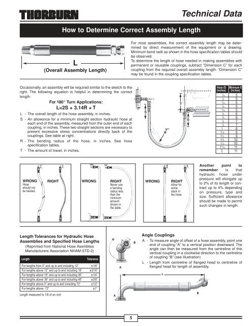
How to Determine Correct Assembly LengthTechnical DataL(Overall Assembly Length)For most assemblies, the correct assembly length may be determinedby direct measurement of the equipment or a drawing.Minimum bend radii as shown in the hose specification tables shouldbe observed.To determine the length of hose needed in making assemblies withpermanent or reusable couplings, subtract “Dimension C” for eachcoupling from the required overall assembly length. “Dimension C”may be found in the coupling specification tables.Occasionally, an assembly will be required similar to the sketch to theright. The following equation is helpful in determining the correctlength:For 180° Turn Applications:L=2S + 3.14R + TL - The overall length of the hose assembly, in inches.S - An allowance for a minimum straight section hydraulic hose ateach end of the assembly, measured from the outer end of eachcoupling, in inches. These two straight sections are necessary toprevent excessive stress concentrations directly back of thecouplings. See table at right.R - The bending radius of the hose, in inches. See hosespecification tables.T - The amount of travel, in inches.SRTS WRONGRIGHTWRONGRIGHTWRONGRIGHTAnother point toremember is thathydraulic hose underpressure will elongate upto 2% of its length or contractup to 4% dependingon pressure, type andsize. Sufficient allowanceshould be made to permitsuch changes in length.Length Tolerances for Hydraulic HoseAssemblies and Specified Hose Lengths(Reprinted from National Hose AsembliesManufacturers Association NHAM-STD-2)A°AABAngle CouplingsA - To measure angle of offset of a hose assembly, point oneend of coupling “A” to a vertical position downward. Theangle can then be measured from the centreline of thisvertical coupling in a clockwise direction to the centrelineof coupling “B” (see illustration)L - Length from centreline of flanged head to centreline offlanged head for length of assembly.LB5
Technical DataHose Routing and InstallationUnder pressure, a hose’s length maychange. Always provide some slack inthe hose to allow for shortening or elongation.However, excessive slack in hoselines may cause poor appearance.When hose lines pass near an exhaustmanifold or other heat source, they shouldbe insulated by a heat resistant boot,firesleeve or a metal baffle. In any application,brackets and clamps keep hoses inplace and reduce abrasion. For installationswhere abrasion to the hose cover cannotbe prevented by using clamps or brackets,a steel protective coil or abrasion resistantsleeve should be placed over the hose.At bends, provide sufficient hose to avoida bend radius less than the hose’s recommendedminimum bend radius. Too tight abend may kink the hose and restrict orsnap the fluid flow. In most cases, theproper use of adapters and hose fittingscan eliminate tight bends or kinks.90°When 90° adapters are used, this assemblybecomes neater looking, easier toinspect and maintain, and uses less hose.1”MinimumBend RadiusIf a hose is installed with a twist in it,operating pressures tend to force it tostraighten. This can loosen the fittingnut. Twisting can cause reinforcementseparation and the hose could burst atthe point of strain.In applications where there is considerablevibration or flexing, allow additionalhose length. The metal hose fittings, naturally,are not flexible, and proper installationprotects metal parts from unduestress, and avoids kinks in the hose.Cleaning, Inspection, Testing and Storage of Hose AssembliesMaintenanceHose assemblies in operation should beinspected frequently for leakage, kinking,abrasion, corrosion or any othersigns of wear or damage. Worn or damagedhose assemblies should bereplaced immediately.CleanClean assembly byblowing out with cleancompressed air.Assemblies may berinsed out with mineralspirits if the tube stock is compatible withoil. Otherwise hot water at 150°F. maximummay be used. Consult Thorburn forspecial cleaning equipment.InspectExamine hose assemblyinternally with a boroscopeor flashlight for cutor bulged tube, obstructions,and cleanliness.Check for proper gapbetween nut and socket or hex and socket.Nuts should swivel freely. Check thelayline of the hose to be sure that theassembly is not twisted. Cap the ends ofthe hose with plastic covers to keep clean.Proof test (hydrostatic)The hose assembly should be hydrostaticallytested at twice the recommendedworking pressure of the hose.Test pressure should be held for notmore than one minute and not less than30 seconds. When test pressure isreached, visually inspect hose assemblyfor: any leaks or signs of weakness; anymovement of the hose fitting in relationto the hose. Any of these defects arecause for rejection.Caution: testingshould be conductedinapproved teststands with adequateguards toprotect theoperator.6Proof test (pneumatic)Hose assembliesintended fo gas or airservice should be testedwith air or nitrogenat 100 psi with theassembly immersed inwater. Random bubblesmay appear over the hose and fittingarea when assembly is first pressurized.This should not be construed as adefect. However, if the bubbles persist informing at a steady rate at any particularpoint on the hose, the assembly shouldbe rejected.Caution: testing should be conducted inapproved test stands with adequateguards to protect the operator.Storage and handlingHose should be stored in a dark, dryatmosphere away from electrical equipment,and the temperature should notexceed 90°F. Storage in the original shippingcontainer is preferred.
- Page 1 and 2: Thorburn Flex IncFlexible Piping Sp
- Page 3 and 4: EMPLOYEESThorburn people are the ke
- Page 5: Thorburn's "Tight weave" braid desi
- Page 9 and 10: Technical Data7. Symptom: The hose
- Page 11 and 12: Technical DataFlow Capacities of Ho
- Page 13 and 14: Hydraulic HosesMedium Pressure1-Wir
- Page 15 and 16: Special Purpose Hose AssembliesTher
- Page 17 and 18: NPTF Solid MaleFemale Flat-Face “
- Page 19 and 20: JIC Swivel FemaleJIC Swivel Female
- Page 21 and 22: “O” Ring Flange 90°Bent Tube(C
- Page 23 and 24: British ThreadingBSPP Solid MaleBSP
- Page 25 and 26: DIN (Deutsche Industrial Norme) Cou
- Page 27 and 28: Stainless Steel Thor-Crimp Series I
- Page 29 and 30: Stainless Steel Thor-Crimp Series I
- Page 31 and 32: Carbon Steel Thor-Crimp Series IV S
- Page 33 and 34: Stainless Steel Thor-Crimp Series V
- Page 35 and 36: Thor-Crimp Series VI Spiral Stems
- Page 37 and 38: Pressure Washer Hose Assemblies “
- Page 39 and 40: N23TWX Ultra High Pressure HosePres
- Page 41 and 42: 40Special Purpose Hose AssembliesPa
- Page 43 and 44: Special Purpose Hose AssembliesSAE
- Page 45 and 46: STRAIGHT-THROUGHNT82 Quick Coupling
- Page 47 and 48: ISO Series B InterchangeNT72 Quick
- Page 49 and 50: T75 Series: High Pressure Couplings
- Page 51 and 52: Thorburn Flex IncFlexible Piping Sp
How to Determine Correct Assembly LengthTechnical DataL(Overall Assembly Length)For most assemblies, the correct assembly length may be determinedby direct measurement of the equipment or a drawing.Minimum bend radii as shown in the hose specification tables shouldbe observed.To determine the length of hose needed in making assemblies withpermanent or reusable couplings, subtract “Dimension C” for eachcoupling from the required overall assembly length. “Dimension C”may be found in the coupling specification tables.Occasionally, an assembly will be required similar to the sketch to theright. The following equation is helpful in determining the correctlength:For 180° Turn Applications:L=2S + 3.14R + TL - The overall length of the hose assembly, in inches.S - An allowance for a minimum straight section hydraulic hose ateach end of the assembly, measured from the outer end of eachcoupling, in inches. These two straight sections are necessary toprevent excessive stress concentrations directly back of thecouplings. See table at right.R - The bending radius of the hose, in inches. See hosespecification tables.T - The amount of travel, in inches.SRTS WRONGRIGHTWRONGRIGHTWRONGRIGHTAnother point toremember is thathydraulic hose underpressure will elongate upto 2% of its length or contractup to 4% dependingon pressure, type andsize. Sufficient allowanceshould be made to permitsuch changes in length.Length Tolerances for <strong>Hydraulic</strong> <strong>Hose</strong><strong>Assemblies</strong> and Specified <strong>Hose</strong> Lengths(Reprinted from National <strong>Hose</strong> AsembliesManufacturers Association NHAM-STD-2)A°AABAngle CouplingsA - To measure angle of offset of a hose assembly, point oneend of coupling “A” to a vertical position downward. Theangle can then be measured from the centreline of thisvertical coupling in a clockwise direction to the centrelineof coupling “B” (see illustration)L - Length from centreline of flanged head to centreline offlanged head for length of assembly.LB5


