Hydraulic Hose Assemblies - Thorburn Flex Inc
Hydraulic Hose Assemblies - Thorburn Flex Inc
Hydraulic Hose Assemblies - Thorburn Flex Inc

You also want an ePaper? Increase the reach of your titles
YUMPU automatically turns print PDFs into web optimized ePapers that Google loves.
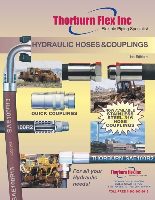
<strong>Thorburn</strong> <strong>Flex</strong> <strong>Inc</strong><strong>Flex</strong>ible Piping SpecialistHYDRAULIC HOSES& COUPLINGS1st EditionQUICK COUPLINGSNOW AVAILABLESTAINLESSSTEEL 316HOSECOUPLINGSFor all your<strong>Hydraulic</strong>needs!<strong>Thorburn</strong> <strong>Flex</strong> <strong>Inc</strong><strong>Flex</strong>ible Piping Specialist173 Oneida Drive, Pointe-Claire,Quebec, Canada H9R 1A9Tel.: (514) 695-8710 Fax: (514) 695-8716TOLL-FREE 1-800-363-6613
<strong>Thorburn</strong> <strong>Flex</strong> <strong>Inc</strong><strong>Flex</strong>ible Piping SpecialistISO9001<strong>Thorburn</strong>’s Innovative <strong>Hydraulic</strong> Connector TechnologyTHORBURN offers unmatchedcapabilities and expertise inapplications engineering,design, development andmanufacturing of flexible pipingsystems. Operating undera strategy of global presencein niche markets, the business is structured to consistently meetand exceed customer expectations of quality and value. Targeting<strong>Thorburn</strong>’s resources allows its core technology to be leveragedand maximized into hundreds of demanding applications.■ Inhouse design,manufacturingand testingcapabilitiesShown is Jack <strong>Thorburn</strong>, who founded the companyin 1954, enjoying one of his passions, sailing.Unfortunately, Jack passed away on February 16th,1995. He will be sorely missed. The company’s leadershippassed on to Jack’s eldest son, Robert, inSeptember 1994.■ 316SS <strong>Hydraulic</strong> <strong>Hose</strong>Couplings for SAE100R2,SAE100R12, SAE100R13
EMPLOYEES<strong>Thorburn</strong> people are the key factor in bringing together its technological, engineering,manufacturing, quality assurance and administrative resources to provide ourcustomers with total satisfaction.Our employees, representing over twenty nationalities have turned <strong>Thorburn</strong> into alean manufacturing company. We are flexible, ready to respond instantly to customerneeds with products and services unique in our industry.THE HEART & SOUL OF THE COMPANYOur people have turned <strong>Thorburn</strong> into a lean manufacturing company. Weare flexible, ready to respond instantly to customer needs with products andservices unique in our industry.Through our combined efforts, we have designed systems for administration,engineering and manufacturing, based on our experience and knowledgegained from each customer and application.CANDU BUSINESS UNITTHORBURN offers unmatched capabilities and expertise inapplications engineering, design development and manufacture ofnon-metallic and metallic flexible piping systems for Candu nuclearpower plants. Operating under a strategy of global presence, <strong>Thorburn</strong>has developed a Candu business unit to service this niche marketsector. <strong>Thorburn</strong>’s nuclear components consistently meet and exceedall the quality design requirements of our Candu nuclear reactorbusiness partners.TOTAL CUSTOMER SATISFACTIONOur company may be known by its products but <strong>Thorburn</strong> knowsthat its products are the result of people whose combinedcompetences build value, work towards excellence and keep thecustomer satisfied. <strong>Thorburn</strong> people are the key factor in bringingtogether its technological, engineering, manufacturing, qualityassurance and administrative resources to provide the customerwith total satisfaction.QUALITY POLICYQuality Assurance is a company culture at <strong>Thorburn</strong> which has beendeveloped by a comprehensive Quality Management System; itrequires the dedication, involvement and motivation of <strong>Thorburn</strong>’spersonnel at all levels of operation to ensure customer satisfactionand facilitate the continuous improvement process.
Table of ContentsTechnical Data 3-9How to Determine Correct <strong>Hose</strong>Assembly Length ______________________________ 3<strong>Hose</strong> Routing and Installation ____________________ 4Cleaning, Inspection, Testing and Storage of <strong>Hose</strong><strong>Assemblies</strong> __________________________________ 4Analyzing Failures ____________________________ 5How to Order <strong>Thorburn</strong> <strong>Hose</strong> <strong>Assemblies</strong> __________ 7Flow Capacities of <strong>Hose</strong> <strong>Assemblies</strong> atRecommended Flow Velocities __________________ 8<strong>Hose</strong> Pressure Drop____________________________ 9<strong>Hydraulic</strong> <strong>Hose</strong>s 10-13Low Pressure <strong>Hose</strong>s __________________________ 10Medium Pressure <strong>Hose</strong>s ______________________ 11High Pressure <strong>Hose</strong>s __________________________ 12Extra High Pressure <strong>Hose</strong>s ____________________ 12Extra Extra High Pressure <strong>Hose</strong>s ________________ 13Ferrules & Stems 14-35Thor-Crimp Series I Ferrules & Stems forTC4 & TG4H <strong>Hose</strong>s __________________________14Series II Ferrules for TC1T, TC2T, TM4K,TG3K, TG2AT-HMP & TM2T <strong>Hose</strong>s ______________15Thor-Crimp Series II Stainless Steel Stems & Ferrules __16Thor-Crimp Series II Carbon SteelStems & Ferrules __________________________17-21British Threading ______________________________22Komatsu & JIS Couplings ______________________23DIN (Deutsche Industrial Norme)Couplings ________________________________24-25Thor-Crimp Series IV Stainless Steel Spiral (TCS)Stems and Ferrules for TC12 & TR9R <strong>Hose</strong> ______26-28Thor-Crimp Series IV Carbon Steel Ferrules & Stems forTC12 &TR9R <strong>Hose</strong> ________________________29-31Thor-Crimp Series VI Stainless Steel (TCH)Stems for TC13 &TG6K <strong>Hose</strong> __________________32Thor-Crimp Series VI (TCH) Carbon Steel Stems& Ferrules for TC13 &TG6K <strong>Hose</strong> ______________33-35Pressure Washer <strong>Hose</strong> <strong>Assemblies</strong> 38-40Aqua Therm Series ________________________ 38-39Elastomeric Waterblast ________________________ 40Special Purpose <strong>Hose</strong> <strong>Assemblies</strong> 41-48Thermoplastic <strong>Hose</strong> ________________________ 41-42Medium Pressure <strong>Hose</strong> ________________________ 43Military Low Pressure <strong>Hose</strong> __________________ 44-45Couplings For Special Purpose <strong>Hose</strong>s __________ 46-48Accessories 49Protective Nylon Sleeve ________________________ 49Quick Couplings 50-58ISO Series NT82 Straight-Through Quick DisconnectCouplings __________________________________ 51ISO Series T61 Interchange Quick DisconnectCouplings __________________________________ 52ISO Series NT72 Interchange Series Quick DisconnectCouplings __________________________________ 53Series T70 High Pressure Quick DisconnectCouplings ________________________________ 54-55Series T71 Flush Face Dry Break Couplings________ 56Series N75 High Pressure Couplings ____________ 57<strong>Thorburn</strong>’s Warranty __________________________ 58
<strong>Thorburn</strong>'s "Tight weave" braid design is carefullycalculated to ensure that the number of wiregauge and the angle of lay give optimumperformance. After the attachment of the endfittings, the hose is pressure tested to 1-1/2 timesthe design pressure.
How to Determine Correct Assembly LengthTechnical DataL(Overall Assembly Length)For most assemblies, the correct assembly length may be determinedby direct measurement of the equipment or a drawing.Minimum bend radii as shown in the hose specification tables shouldbe observed.To determine the length of hose needed in making assemblies withpermanent or reusable couplings, subtract “Dimension C” for eachcoupling from the required overall assembly length. “Dimension C”may be found in the coupling specification tables.Occasionally, an assembly will be required similar to the sketch to theright. The following equation is helpful in determining the correctlength:For 180° Turn Applications:L=2S + 3.14R + TL - The overall length of the hose assembly, in inches.S - An allowance for a minimum straight section hydraulic hose ateach end of the assembly, measured from the outer end of eachcoupling, in inches. These two straight sections are necessary toprevent excessive stress concentrations directly back of thecouplings. See table at right.R - The bending radius of the hose, in inches. See hosespecification tables.T - The amount of travel, in inches.SRTS WRONGRIGHTWRONGRIGHTWRONGRIGHTAnother point toremember is thathydraulic hose underpressure will elongate upto 2% of its length or contractup to 4% dependingon pressure, type andsize. Sufficient allowanceshould be made to permitsuch changes in length.Length Tolerances for <strong>Hydraulic</strong> <strong>Hose</strong><strong>Assemblies</strong> and Specified <strong>Hose</strong> Lengths(Reprinted from National <strong>Hose</strong> AsembliesManufacturers Association NHAM-STD-2)A°AABAngle CouplingsA - To measure angle of offset of a hose assembly, point oneend of coupling “A” to a vertical position downward. Theangle can then be measured from the centreline of thisvertical coupling in a clockwise direction to the centrelineof coupling “B” (see illustration)L - Length from centreline of flanged head to centreline offlanged head for length of assembly.LB5
Technical Data<strong>Hose</strong> Routing and InstallationUnder pressure, a hose’s length maychange. Always provide some slack inthe hose to allow for shortening or elongation.However, excessive slack in hoselines may cause poor appearance.When hose lines pass near an exhaustmanifold or other heat source, they shouldbe insulated by a heat resistant boot,firesleeve or a metal baffle. In any application,brackets and clamps keep hoses inplace and reduce abrasion. For installationswhere abrasion to the hose cover cannotbe prevented by using clamps or brackets,a steel protective coil or abrasion resistantsleeve should be placed over the hose.At bends, provide sufficient hose to avoida bend radius less than the hose’s recommendedminimum bend radius. Too tight abend may kink the hose and restrict orsnap the fluid flow. In most cases, theproper use of adapters and hose fittingscan eliminate tight bends or kinks.90°When 90° adapters are used, this assemblybecomes neater looking, easier toinspect and maintain, and uses less hose.1”MinimumBend RadiusIf a hose is installed with a twist in it,operating pressures tend to force it tostraighten. This can loosen the fittingnut. Twisting can cause reinforcementseparation and the hose could burst atthe point of strain.In applications where there is considerablevibration or flexing, allow additionalhose length. The metal hose fittings, naturally,are not flexible, and proper installationprotects metal parts from unduestress, and avoids kinks in the hose.Cleaning, Inspection, Testing and Storage of <strong>Hose</strong> <strong>Assemblies</strong>Maintenance<strong>Hose</strong> assemblies in operation should beinspected frequently for leakage, kinking,abrasion, corrosion or any othersigns of wear or damage. Worn or damagedhose assemblies should bereplaced immediately.CleanClean assembly byblowing out with cleancompressed air.<strong>Assemblies</strong> may berinsed out with mineralspirits if the tube stock is compatible withoil. Otherwise hot water at 150°F. maximummay be used. Consult <strong>Thorburn</strong> forspecial cleaning equipment.InspectExamine hose assemblyinternally with a boroscopeor flashlight for cutor bulged tube, obstructions,and cleanliness.Check for proper gapbetween nut and socket or hex and socket.Nuts should swivel freely. Check thelayline of the hose to be sure that theassembly is not twisted. Cap the ends ofthe hose with plastic covers to keep clean.Proof test (hydrostatic)The hose assembly should be hydrostaticallytested at twice the recommendedworking pressure of the hose.Test pressure should be held for notmore than one minute and not less than30 seconds. When test pressure isreached, visually inspect hose assemblyfor: any leaks or signs of weakness; anymovement of the hose fitting in relationto the hose. Any of these defects arecause for rejection.Caution: testingshould be conductedinapproved teststands with adequateguards toprotect theoperator.6Proof test (pneumatic)<strong>Hose</strong> assembliesintended fo gas or airservice should be testedwith air or nitrogenat 100 psi with theassembly immersed inwater. Random bubblesmay appear over the hose and fittingarea when assembly is first pressurized.This should not be construed as adefect. However, if the bubbles persist informing at a steady rate at any particularpoint on the hose, the assembly shouldbe rejected.Caution: testing should be conducted inapproved test stands with adequateguards to protect the operator.Storage and handling<strong>Hose</strong> should be stored in a dark, dryatmosphere away from electrical equipment,and the temperature should notexceed 90°F. Storage in the original shippingcontainer is preferred.
Technical Data<strong>Hose</strong> failures normally aren’t a problem– the hose is replaced and the equipment goes back in operation. However, whenthe same problems keep occuring with the same equipment, one must determine their causes and correct them.Improper ApplicationBegin with the most obvious and commoncause of hose failures, improper application,and compare the hose specifications withthe requirements of the application. Payattention especially to the following:1. Maximum operating pressure of thehose.2. Recommended temperature range ofthe hose.3. Whether the hose is rated forvacuum service.4. Fluid compatibility of the hose.Check these against the requirements of theapplication. If they don’t match up, anotherhose must be selected. A <strong>Thorburn</strong> representativecan help you select the proper hose.Analyzing FailuresA physical examination of the failed hose can often offer a clue to the cause of failure. Following are 20 symptomsto look for, along with the conditions causing them:1. Symptom: The hose tube is very hardand has cracked.Analyzing FailuresImproper Assembly and InstallationThe second major cause of premature hosefailures is improper assembly and installationprocedures. This can involve any factorfrom using the wrong hose fitting to poorrouting of the hose.Your <strong>Thorburn</strong> representativecan help you solve this problem.External DamageExternal damage ranges from abrasion andcorrosion to a hose crushed by a forklift truck.Once the cause is identified, most of theseproblems are easily solved. The hose can bere-routed or clamped or a fire sleeve or abrasionguard can be used. With corrosion, thesolution may simply be to switch to a hose witha more corrosion resistant cover or re-routingthe hose away from the corrosive element.3. Symptom: The hose has burst.Examination of the wire reinforcementafter stripping back the cover reveals randombroken wires the entirelength of the hose.Faulty EquipmentA malfunction in equipment is a factor to beconsidered since prompt corrective actioncan avoid serious and costly equipmentbreakdown.Faulty <strong>Hose</strong>Sometimes a failure is caused by the hoseitself. The likeliest cause of a faulty rubberhose is old age. Check the lay line on the hoseto determine the date of manufacture. Thehose may have exceeded its recommendedshelf life. If, after exhausting other possibilities,you suspect the problem is in the manufactureof the hose, contact <strong>Thorburn</strong>. Given effectivequality control methods, the odds of a faultyhose being released for sale are tiny.deteriorated badly.Cause: Heat has a tendency to leach theplasticizers out of the tube. This is amaterial that gives the hose its flexibilityor plasticity. Aerated oil causes oxidationto occur in the tube. This reaction of oxygenand heat will greatly accelerate thehardening of the hose tube. Cavitationoccuring inside the tube would have thesame effect.2. Symptom: The hose is cracked bothexternally and internally but the elastomericmaterials are soft and flexible atroom temperature.Cause: Probably the hose was flexedunder intense cold ambient conditions.Most standard hoses are rated to -40°F(-40°C). Some <strong>Thorburn</strong> hoses are ratedat -55°F (-49°C). Military specified hosesare commonly rated to -65°F (-54°C).Teflon hose is rated to -100°F (-73°C).Some Polyon thermoplastic hoses arerated -65°F (-54°C).Cause: This points to a high frequencypressure impulse condition. SAE impulsetest requirements for a double wire braidreinforcement are 200,000 cycles at 133%of the recommended working pressure.The SAE impulse test requirements for afour spiral wrapped braid reinforcement(100R9) are 300,000 cycles at 133% ofthe recommended working pressure andat 200°F (93°C). If the extrapolated impulsesin a system amount to over a million ina relatively short time a spiral reinforcedhose would be the better choice.4. Symptom: The hose has burst, but thereis no indication of multiple broken wiresthe entire length of the hose. The hosemay have burst in more than oneplace.Cause: The pressure has exceeded minimumstrength of the hose. Either astronger hose is needed or the hydrauliccircuit has a malfunction which is causingunusually high pressure conditions.5. Symptom: The hose has burst. An examinationreveals that the wire braid is rustedand the cover has been cut, abraded or7Cause: The primary function of the cover isto protect the reinforcement. Elements thatmay destroy or remove the hose covers are:1. abrasion2. cutting3. battery acid4. steam cleaners5. chemical cleaning solutions6. muriatic acid (for cement clean-up)7. salt water8. heat9. extreme coldOnce the cover protection is gone, the wirereinforcement is susceptible to attack frommoisture or other corrosive matter.6. Symptom: The hose has burst on the outsidebend and seems elliptical in the bentsection. In the case of the pump supply line,the pump is noisy and very hot. Theexhaust line on the pump is hard and brittle.Cause: In both cases, the likeliest cause isa violation of the minimum bend radius.Check the minimum bend radius and makesure that it is within specifications. In thecase of pump supply line partial collapse ofthe hose is causing the pump to cavitatecreating both noise and heat. This is a mostserious situation and will result in catastrophicpump failure if not corrected.
Technical Data7. Symptom: The hose appears flattened outin two areas and kinked. It has burst in thisarea and also appears twisted.Cause: Torquing of a hydraulic control hosetears loose the reinforcement layers andallows the hose to burst through enlargedgaps between the braided plaits of wirestrands. Use swivel fittings or joints to avoid atwisting force on a hydraulic hose.8. Symptom: The hose tube is broken loosefrom the reinforcement and piled up at theend of the hose. It may protrude from theend of the hose fitting.Cause: Likely cause: high vacuum or wronghose for the vacuum service. No vacuum isrecommended for double wire braid, 4 and 6spiral wire hose unless an internal coil supportis used. This type of failure may happen evento a hose rated for vacuum service, if it iskinked, flattened out or bent too sharply, .9. Symptom: The hose has burst about six toeight inches away from the end fitting. Thewire braid is rusted. There are no cuts orabrasions of the outer cover.Cause: Improper assembly of the hose endfitting allows moisture to enter around theedge of the fitting socket. The moisture willwick through the reinforcement.The heat generatedby the system will drive it out aroundthe fitting area, but six inches away it will betrapped between inner liner and outer cover,causing corrosion of the wire reinforcement.10. Symptom: There are blisters on the coverof the hose. If one pricks the blisters, oil willbe found in them.Cause: A tiny pinhole in the hose tube isallowing high pressure oil to seep betweenit and the cover. Eventually, it will form ablister where the cover adhesion is weakest.For a screw-together reuseable fitting,insufficient lubrication of the hose and fittingcan cause this condition because the drytube will adhere to the rotating nipple andtear enough to allow seepage. Faulty hosecan also cause this condition.11. Symptom: Blistering of the hose coverwhere a gaseous fluid is being used.Cause: High pressure gas effuses throughthe hose tube, gathering under the coverand soon forming a blister where the adhesionis weakest. Specially constructedhoses are available for high pressuregaseous applications. Your <strong>Thorburn</strong> representativecan advise you on the properhose to use in these cases.12. Symptom: Fitting blew off end of hose.Cause: Wrong fitting on the hose. Recheck<strong>Thorburn</strong>’’s specifications and part numbers.For a crimped fitting, the wrong machinesetting can result in over- or undercrimping.The socket of a screw together-fittingfor multiple wire braided hose may be wornbeyond its tolerance.The swaging dies in aswaged hose assembly may be wornbeyond <strong>Thorburn</strong>’s tolerances.The fitting may have been appliedimproperly to the hose. Check <strong>Thorburn</strong>’sinstructions. The hose may have beeninstalled without leaving enough slack tocompensate for the possible 4% shorteningthat may happen when a hose is pressurized,imposing great force on the fitting. Thehose itself may be out of tolerance.13. Symptom: The tube of the hose is badlydeteriorated with evidence of extremeswelling. In some cases, the hose tubemay be “washed out”.Cause: This indicatesthat the hose tube is notcompatible with theagent being carried.Even though the agentis normally compatible,the addition of heat canbe the catalyst that cancause inner liner deterioration. Consult<strong>Thorburn</strong> for a compatibility list. Make sureneither the internal nor the external operatingtemperatures exceed recommendations.14. Symptom: The hose has burst. The hosecover is badly deteriorated and the surfaceof the rubber is crazed.Cause: This could be simply old age. Thecrazed appearance is the effect of weatheringand ozone over a period of time. Tryto determine the age of the hose.<strong>Thorburn</strong> prints or embosses the date onthe outside of the hose.15. Symptom: The hose leaks at the fittingbecause of a crack in the metal tube adjacentto the braze on a split flange head.Cause: Because the crack is adjacent tothe braze, this is a stress failure brought onby a hose that is trying to shorten underpressure, but does’t have sufficient slack todo so.This problem can be cured by lengtheningthe hose assembly or altering therouting to relieve the forces on the fitting.16. Symptom: A spiral reinforced hose hasburst and literally split open with the wireexploded out and badlyentangled.Cause:The hose is too short toaccomodate the changein length occurring while it is pressurized.17. Symptom: The hose hasn’t burst, but isleaking profusely. A bisection of the hosereveals that the tube has been gougedthrough to the wire braid for a distance ofabout two inches.Cause: Indicates erosion of the hose tube.A high velocity needle-like fluid stream beingemitted from an orifice and impinging at asingle point on the hose tube will hydraulicallyremove a section of it. Be sure thehose is not bent close to an orificed port.18. Symptom: The hose is badly flattenedout in the burst area. The tube is veryhard downstream of the burst butappears normal upstream of the burst.Cause: The hose has been kinked either bybending it too sharply or by squashing it soas to create a major restriction. As the velocityof the fluid increases through the restriction,the pressure decreases to the vaporizationpoint of the fluid being conveyed.Often called cavitation, it causes heat andrapid oxidation to occur, hardening the hosetube downstream of the restriction.19. Symptom: The hose fitting has been pulledout of the hose. The hose has been considerablystretched out in length. This may notbe a high pressure application.Cause: Insufficient support of the hose.Very long lengths of hose must be supported,especially if vertical. Otherwise, theweight of the hose along with the weight ofthe fluid in it will be imposed on the hose fitting.This force can be transmitted to a wirerope or chain by clamping the hose to itmuch like the utilities support bundles ofwire from pole to pole. Leave sufficient slackin the hose between clamps to compensatefor possible 4% shortening that can occurwhen the hose is pressurized.20. Symptom: The hose has not burst, but itleaks profusely. A bisection of the hosereveals an inward burst.Cause: Often known as hose tube blowdown,this type of failure is usually associatedwith very low viscosity fluids such as air,nitrogen, freon, and other gases. Under highpressure conditions, the gases effuse intothe pores of the hose tube charging them uplike miniature accumulators. If the pressure issuddenly reduced to zero, the entrappedgases literally explode out of the tube, oftentearing holes in it. In some hose constructions,a second hose tube made from a plasticsuch as nylon, is inserted into the hose.A small leak allows the gaseous fluid toseep between the two inner liners andwhen the pressure is reduced to zero, theinnermost liner will collapse because of thetrapped pressure around its outer diameter.8
The example shown here:TC4 3/4” <strong>Hose</strong> with Series I “O”Ring Flange Straight 3/4” at firstend and Thorcrimp NPTF SolidMale 3/4” at second end.HOW TO ORDER THORBURN HOSE ASSEMBLIES1st EndOverall LengthTechnical Data2nd End 9
Technical DataFlow Capacities of <strong>Hose</strong> <strong>Assemblies</strong> at Recommended Flow Velocities Nomographic ChartIndicating Flow Capacity of <strong>Hose</strong> <strong>Assemblies</strong> atRecommended Flow VelocitiesBased on Formula:Area (Sq. In.) =10 0.321 x GPMVelocity (Ft./Sec.)Suggestions are for oils having a maximum viscosity of 315 SSU at 100° F. (38°C.), operating at temperatures between 65°F. (54° C.) and 155°F. (69° C). Undercertain conditions, velocities in pressure lines can be increased up to 25 feet persecond. Contact <strong>Thorburn</strong> with specific information on your application.
Technical Data<strong>Hose</strong> Pressure DropPressure drop in psi (pounds per square inch) / gpm (gallons per minute) for 10 feet of hose(smooth bore) without fittings.Fluid specifications: Specific gravity=.85; Viscosity=v=20 centistokes (C.S.), (20 C.S. = 97S.S.U.).<strong>Hose</strong> Dash Size ➝ -03 -04 -05 -06 -08 -10 -12 -16 -20 -24 -32 -40 -48<strong>Hose</strong> ID (inches) .19 .25 .31 .38 .50 .63 .75 1.00 1.25 1.50 2.00 2.38 3.00.25 10 3.1.50 19 6 2.71 40 12 5.5 2.42 95 24 10 4.83 185 46 17 7 2.2478 29 12 3 1.25120 44 18 4.5 1.6 .72895 39 10 3.6 1.41059 15 5.7 2 .551280 20 7.2 2.6 .751530 10 4.2 1.2 .381840 15 6.3 1.5 .552049 19 8 2 .65 .272572 26 11 3 1 .403034 14 3.6 1.3 .52 .143547 19 5 1.7 .70 .184025 6.5 2.2 .90 .245036 9 3.3 1.3 .35 .156050 12 4.4 1.8 .45 .207017 6 2.4 .65 .308021 7.1 3 7.6 .34 .119027 9 3.8 1 .45 .1310033 12 4.7 1.3 .55 .1815060 22 8.5 2.2 1 .3320036 15 3.9 1.7 .5525054 22 5.3 2.5 .7530029 7.5 4 1.140051 14 6.5 2.250020 10 3800100018 510U.S. gallons per minute➝ 11
<strong>Hydraulic</strong> <strong>Hose</strong>sMedium Pressure1-Wire Braid <strong>Hose</strong> SAE 100R1 Type ATOne wire braid hose. “No-Skive” typehydraulic hose. Meets or exceedsrequirements of SAE 100R2, Type AT.Excellent high and low temperaturerange. <strong>Hose</strong> also meets FlameResistance Acceptance DesignationU.S. MSHA 2G. No skiving required.Recommended for: Medium pressurehydraulic oil lines.Temperature Range: -40°C to +100°C(-40°F to +212°F). Higher temperaturecompounds available.Couplings: Thor-Crimp Couplings SeriesII pages 15-24.Tube: Black. Oil resistant synthetic rubber.Reinforcement: One braid of high tensilesteel wire.Cover: Black. Oil and abrasion resistant,thin synthetic rubber.TR1 1-Wire Braid <strong>Hose</strong> 3000 psi SAE 100R17Half the bend radius of SAE 100R1TR17Recommended for: Medium pressurehydraulic oil lines. Exceeds SAE performancerequirements because TM3Khose has smaller interior dimensionsand significantly tighter bendradius… up to half SAE rating.Temperature Range: -40°C to +100°C(-40°F to +212°F).Couplings: Thor-Crimp Couplings SeriesII pages 15-24.Tube: Black, oil resistant synthetic rubber.Reinforcement: Braided high tensilesteel wire.Cover: Black. Oil, abrasion and weatherresistant, synthetic rubber. 2-Wire Braid <strong>Hose</strong> SAE 100R2 Type AT“No-Skive” type hydraulic hose. Meets orexceeds requirements of SAE 100R2,Type AT. Used with Thorcrimp where“No-Skive” hose is required. Excellenthigh and low temperature range. <strong>Hose</strong>also meets Flame ResistanceAcceptance Designation U.S. MSHA 2G.Recommended for: Medium pressurehydraulic oil lines, fuel oil, or water. Usedon all types of hydraulic systems formobile and stationary equipment.Temperature Range: -40°C to +100°C(-40°F to +212°F). Higher temperaturecompounds available.Couplings: Thor-Crimp Couplings SeriesII pages 15-24.Tube: Black. Oil resistant synthetic rubber.Reinforcement: Two braids of high tensilesteel wire.Cover: Black. Oil and abrasion resistant,thin synthetic rubber.TR2 12
<strong>Hydraulic</strong> <strong>Hose</strong>sHigh Pressure2-Wire Braid <strong>Hose</strong> SAE 100R16Half the bend radius of SAE 100R2“No-Skive” type hydraulic hose. of SAE100R2, Type AT. Used with <strong>Thorburn</strong>Thorcrimp System where “No-Skive”hose is required. Excellent high and lowtemperature range.Recommended for: High pressurehydraulic oil lines. Meets or exceedsSAE requirements, with smaller exteriordimensions and significantly tighterbend radius.Temperature Range: -40°C to +100°C(-40°F to +212°F).Couplings: Thor-Crimp Couplings SeriesII pages 15-24.Tube: Black. Oil resistant synthetic rubber.Reinforcement: Two braids of high tensilesteel wire.Cover: Black. Oil and abrasion resistant.TR16 Extra High Pressure4-Spiral Wire <strong>Hose</strong> SAE 100R12TR12Recommended for: Extra high pressurehydraulic applications. Excellentimpulse life; surpassed 1,000,000impulse cycles when tested with PCSseries couplings at 250°F (at SAE100R12 conditions) and at 133% ofrated working pressure.Temperature Range: -40°C to +121°C(-40°F to +250°F).Couplings: Thor-Crimp Couplings SeriesIV pages 25-26.Tube: Black. Oil resistant synthetic rubber.Reinforcement: Four alternating layersof spiraled high tensile steel wire over afabric layer.Cover: Black. Oil resistant synthetic rubber. Spiral Wire <strong>Hose</strong> SAE100R135000 psiTR13<strong>Hose</strong> meets Flame ResistanceAcceptance Designation U.S. MSHA 2G.Recommended for: Extremely highpressure hydraulic applications. Meetsall requirements of the SAE 100R13specifications.Temperature Range: -40°C to +121°C(-40°F to +250°F).Couplings: Thor-Crimp Couplings SeriesVI “TCH” pages 30-33.Tube: Black. Oil resistant synthetic rubber.Reinforcement: Four alternating layersof spiraled high tensile steel wire over afabric layer on -12 and -16 sizes; sixalternating layers of spiraled high tensilesteel wire over a fabric layer on -20,-24 and -32 sizes.Cover: Black. Oil resistant syntheticrubber. 13
Special Purpose <strong>Hose</strong> <strong>Assemblies</strong>Thermoplastic <strong>Hose</strong> <strong>Assemblies</strong>TR7NC Thermoplastic Non-Conductive<strong>Hydraulic</strong> <strong>Hose</strong>SAE 100R7CONSTRUCTIONTube: 100% seamless nylon that easily handles a broad rangeof hydraulic fluids, including phosphate esters and water glycol.Non-perforated for applications requiring electrical non-conuctivity.Meets SAE 100R7 electrical conductivity test.Reinforcement: Single polyester braidCover: Orange urethane that resists htdraulic fluids, high temperatures,aging and weathering.Couplings: Factory assembled swage type coupling in carbonsteel or stainless steel.Part Number<strong>Hose</strong> ID<strong>Inc</strong>hes<strong>Hose</strong> OD<strong>Inc</strong>hesDesign PressurePSIMin Burst PressurePSIMin Bend Radius<strong>Inc</strong>hesWeightLBS/100FT2TRNC73TRNC74TRNC75TRNC76TRNC78TRNC712TRNC716TRNC71/83/161/45/163/81/23/410.320.440.510.580.660.821.071.332500300027502500225020001250100010,00012,00011,00010,0009,0008,0005,0004,0000.50.81.31.82.03.05.08.0????????TR8NC Thermoplastic Non-Conductive<strong>Hydraulic</strong> <strong>Hose</strong>SAE 100R84TRNC86TRNC88TRNC8Part Number<strong>Hose</strong> ID<strong>Inc</strong>hes1/43/81/2<strong>Hose</strong> OD<strong>Inc</strong>hes0.520.660.81Design PressurePSI500040003500CONSTRUCTIONTube: 100% seamless nylon that easily handles a broad rangeof hydraulic fluids, including phosphate esters and water glycol.Non-perforated for applications requiring electrical non-conuctivity.Meets SAE 100R8 electrical conductivity test.Reinforcement: Single aramid fiber braidCover: Orange urethane that resists htdraulic fluids, high temperatures,aging and weathering.Couplings: Factory assembled swage type coupling in carbonsteel or stainless steel.Min Burst PressurePSI20,00016,00014,000Min Bend Radius<strong>Inc</strong>hes2.002.504.00WeightLBS/100FT???14
Thor-Crimp Series II FerrulesFerrules for TR1, TR17, TR2, TR16Series II FerruleThe Thor-Crimp AdvantageAB Series II NC FerruleFeatures:■ Ferrule serrations bite thourghthe cover making contact withwire reinforcement■ Machine-fit locking collarbetween ferrule and stem■ Low profile finished crimpBenefits:■ Safety; better holding power andreliability■ Smaller finished crimp; streamlinedassemblies; easier to plumb■ Excellent performanceThe Thor-Crimp SystemA hydraulic hose coupling usually consists of two primary components:1. A ferrule placed over the end of the hose.2. A stem inserted into the end of the hose.<strong>Hose</strong> Ferrule Stem ABNo Weld Flanged ElbowsOne Piece Flanged Coupling.• Eliminates Stress Risers• Safer and more reliable• Eliminates cracks during vibrationSuperior Elbow Threaded CouplingsNo Welded Joints15
NPTF Solid MaleFemale Flat-Face “O” SealSwivel StraightJIC Swivel Female JIC Solid MaleFemale Flat-Face “O” SealSwivel 45° Bent TubeJIC Swivel Female 45°Bent Tube “O” Ring Boss Solid Male Other sizes available on request. Female Flat-Face “O” SealSwivel 90° Bent Tube 16 See page (180)? for Torque values.JIC Swivel Female 90°Bent Tube
NPTF Solid MaleNPTF Swivel Male 90°NPTF Solid Female NPTF Swivel Male JIC Solid Male 17 NPTF Swivel Female
JIC Swivel FemaleJIC Swivel Female 45°Bent TubeJIC Swivel Female 90°Bent Tube Length available on request18
“O” Ring Boss Solid Male“O” Ring Boss SwivelMale 45°“O” Ring Flange Straight(Code 61-SAE J518) “O” Ring Boss SwivelMale 90° *See Adapter section for Flange Halves.“O” Seal Flange 45°Bent Tube(Code 61-SAE J518)“O” Ring Boss Swivel Male 19
“O” Ring Flange 90°Bent Tube(Code 61-SAE J518)“O” Ring Flange Straight(Code 62-SAE J518)“O” Ring Flange 90°Bent Tube(Code 62-SAE J518) *See Adapter section for Flange Halves. *See Adapter section for Flange Halves.“O” Seal Flange 45°Bent Tube(Code 62-SAE J518) *See Adapter section for Flange Halves. 20
Male Flat-Face “O” RingSAE Male FlarelessFemale Flat-Face “O” SealSwivel 90° Bent Tube Female Flat-Face “O” SealSwivel StraightFemale Flat-Face “O” SealSwivel 45° Bent TubeNutSleeve 21
British ThreadingBSPP Solid MaleBSPP Swivel FemaleBSPP Swivel Female90° Bent Tube +<strong>Inc</strong>ludes “O” ring.Male BSPT Tapered BSPP Swivel Female45° Bent Tube 22
Komatsu & JIS CouplingsFemale Komatsu SwivelFemale Komatsu Swivel90° Bent TubeNut HexJapanese SeriesJIS Female Swivel 45°Bent Tube Female Komatsu Swivel45° Bent TubeNut Hex Japanese SeriesJIS Female Swivel JIS Female Swivel 90°Bent Tube 23
DIN (Deutsche Industrial Norme) CouplingsDIN Male Light SeriesDIN Female SwivelStraight Light “O” Ring 24°Inverted ConeDIN Female Swivel Light“O” Ring 24° Cone Series90° Bent Tube DIN Male Heavy Series DIN Female Swivel Light“O” Ring 24° Cone Series45° Bent Tube DIN Female Swivel StraightHeavy Series 24° InvertedCone with “O” Ring 24
DIN Female Swivel Heavy24° Cone Series45° Bent Tube DIN Female Swivel HeavySeries 90° Bent Tube Metric Stand PipeLight/Heavy Series Metric Bite SleeveLight/Heavy SeriesMetric Bite NutLight/Heavy Series 25
Stainless Steel Thor-Crimp Series IV StemsSeries IV FerrulesThor-Crimp Spirals Series IV IIIA / BFerrules for use with TR12 & <strong>Hose</strong>sNon- Skive for TR12 NPTF Solid MaleSkive for TR12 O-Ring Boss Solid Male Female Flat-Face “O” SealSwivel StraightFemale Flat-Face “O” SealSwivel 45° <strong>Thorburn</strong> One piece coupling only. <strong>Thorburn</strong> Female Flat-Face “O” SealSwivel 90° <strong>Thorburn</strong> Other sizes available upon request.26
Stainless Steel Thor-Crimp Series IV StemsMale JIC (37° Flare)Female 37° Flare (JIC)SwivelJIC Swivel Female 90°Bent Tube Other sizes available upon request. JIC Swivel Female 45°Bent Tube Other sizes available upon request. Other sizes available upon request.27
Stainless Steel Thor-Crimp Series IV Stems“O” Seal Flange Straight(Code 61-SAE J518)“O” Seal Flange 45°Bent Tube(Code 61-SAE J518)“O” Seal Flange 90°Bent Tube (Code 61-SAE J518) Other sizes available upon request. Other sizes available upon request. Other sizes available upon request.28
Carbon Steel Thor-Crimp Series IV StemsSeries IV Ferrules Male JIC (37° Flare)JIC Swivel Female 45°Bent Tube O-Ring Boss Solid Male Female 37° Flare (JIC)Swivel JIC Swivel Female 90°Bent TubeNPTF Solid Male **LH=Long Hex 29
Carbon Steel Thor-Crimp Series IV Stems“O” Seal Flange Straight(Code 61-SAE J518)“O” Seal Flange 45°Bent Tube(Code 61-SAE J518)“O” Seal Flange 90°Bent Tube (Code 61-SAE J518) “O” Seal Flange 22 1 /2° - 30°(Code 61-SAE J518) “O” Seal Flange 60° - 67 1 /2°(Code 61-SAE J518) Available upon request.30 “O” Seal Flange 100° - 135°Bent Tube (Code 61-SAE J518) Available upon request.
Carbon Steel Thor-Crimp Series IV Stems“O” Seal Flange Straight(Code 62-SAE J518)“O” Seal Flange 90°Bent Tube (Code 62-SAE J518)Female Flat-Face “O” SealSwivel 45° “O” Seal Flange 45°Bent Tube (Code 62-SAE J518) Male Flat-Face “O” Seal <strong>Thorburn</strong> Female Flat-Face “O” SealSwivel 90° <strong>Thorburn</strong> Female Flat-Face “O” SealSwivel Straight <strong>Thorburn</strong> 31 <strong>Thorburn</strong>
Stainless Steel Thor-Crimp Series VI Spiral StemsSeries VI FerrulesDimensionsavailable uponrequest.Male NPTMaterial 316 Female 37° Flare (JIC)SwivelMaterial 316 Female 37° Flare (JIC)Swivel 45°Material 316 Material 316 Female 37° Flare (JIC)Swivel 45°Material 316 “O” Ring Flange StraightCode 62Material 316 “O” Ring Flange 45°Code 62Material 316 Other sizes and shapes availableupon request.32“O” Ring Flange 90°Code 62 Female Flat-Face “O” SealSwivel StraightMaterial 316 Female Flat-Face “O” SealSwivel 45°Material 316 Female Flat-Face “O” SealSwivel 90°Material 316 Material 316
Thor-Crimp Series VI Spiral StemsMale (JIC) 37° Flare “O” Ring Boss Solid Male Material 316Material 316Series VIFerrulesDimensions availableupon request.Male NPT “O” Ring Boss Solid Male Female 37° Flare (JIC)Swivel Female 37° Flare (JIC)Swivel 45° Female 37° Flare (JIC)Swivel 90°Male (JIC) 37° FlareOther sizes and shapes availableupon request. 33
Thor-Crimp Series VI Spiral Stems“O” Ring Flange Straight“O” Ring Flange 45°“O” Ring Flange 90° “O” Seal Flange 22°(Code 62 - SAE J518)“O” Seal Flange 30°“O” Seal Flange 60° Available upon request. Available upon request.Available upon request.34
Thor-Crimp Series VI Spiral StemsFemale Flat-Face “O” SealSwivel StraightFemale Flat-Face “O” SealSwivel 45°Female Flat-Face “O” SealSwivel 90° <strong>Hose</strong> Length Extender 35
Pressure Washer <strong>Hose</strong> <strong>Assemblies</strong> “Non Marking”3000 psiRECOMMENDED FOR:On hot and cold water high pressure cleaning equipment whereheavy duty service is required. <strong>Thorburn</strong>’s “Aqua Therm-A” modelTPWBLU was specially designed for applications that require nonmarkingcover.WARNING: Not recommended for steam serviceCouplings: “Crimp Type” See following page.Bend restrictors recommended to extend service.ConstructionTube: Black oil, heat and detergent resistantBuna “N” blendReinforcement: High tensile braided steel wireCover: Neoprene specially compounded to benon marking, abrasion, heat, ozone and weatherresistant. Not resistant to animal fatsTemperature: -40° F. to 250° F.(-40° C to 122° C)Lengths: Up to 150 ft. availablePart Number<strong>Hose</strong> ID<strong>Inc</strong>hes<strong>Hose</strong> OD<strong>Inc</strong>hesDesign PressurePSIMin Burst PressurePSIMin Bend Radius<strong>Inc</strong>hesWeightLBS/100FTTPWBLU04TPWBLU06TPWBLU081/43/81/21/25/820/3230003000300012000120001200022.53.5131825Animal Fat & Oil Resistant3000 psiRECOMMENDED FOR:On hot and cold water high pressure cleaning equipment whereheavy duty service is required. <strong>Thorburn</strong>’s “Aqua Therm-B” modelTPWBLK was specially designed for applications that require acover that is resistant to animal fats.WARNING: Not recommended for steam serviceCouplings: “Crimp Type” See following page.Bend restrictors recommended to extend service.ConstructionTube: Black oil, heat and detergent resistantBuna “N” blendReinforcement: High tensile braided steel wireCover: Neoprene specially compounded to beresistant to animal fats, abrasion, heat, ozone andweather resistant. Not resistant toTemperature: -40° F. to 212° F.(-40° C to 100° C)Lengths: Up to 150 ft. availablePart Number<strong>Hose</strong> ID<strong>Inc</strong>hes<strong>Hose</strong> OD<strong>Inc</strong>hesDesign PressurePSIMin Burst PressurePSIMin Bend Radius<strong>Inc</strong>hesWeightLBS/100FTTPWBLK04TPWBLK06TPWBLK081/43/81/20.530.680.8230003000250012000120001000045714232836
Pressure Washer <strong>Hose</strong> <strong>Assemblies</strong>Super Heated Water 350°F @ 350psi (Super Heated Water)RECOMMENDED FOR:Hot and cold high pressure cleaning equipment where heavy dutyservice is required. <strong>Thorburn</strong>’s “Aqua Therm-C” model TPWHTwas specially designed for applications that require cleaning withsuper-heated water at 350° at 350 psi.WARNING: Not recommended for steam serviceCouplings: “Crimp Type” See below.Bend restrictors recommended to extend service.ConstructionTube: Black EPDM heat resistant syntheticrubberReinforcement: High tensile braided steel wireCover: Hypalon cover which provides abrasion,ozone and oil resistanceTemperature: -40° F to 350° F.(-40° C to 177° C)Lengths: Up to 150 ft. availablePart Number<strong>Hose</strong> ID<strong>Inc</strong>hes<strong>Hose</strong> OD<strong>Inc</strong>hesDesign PressurePSIMin Burst PressurePSIMin Bend Radius<strong>Inc</strong>hesWeightLBS/100FTTPWHT06 3/8 0.683000 12000 2 19Typical Crimp Couplings Plated SteelRigid Male NPTMale Swivel37° Female SwivelKarcher (M22 x 1.51)SwivelCode MPCode MPXCode FJXCode KXCouplings also available in stainless steel.Typical PressureWasher Quick Coupling Brass also available in Carbon Steel &Stainless SteelBend RestrictorFemale NippleFemale CouplingCode BRCode QNFCode QCFMarketsIndustrial CleaningMarketsFood IndustryConstruction IndustryMarineAgricultureApplicationsPressure wash engines,equipment, tanks, buildings, androof cleaning, etc.Wash down of food processingfacilities and equipment.High pressure cleaningand degreasing.Boat CleaningPressure wash engines, farmequipment, tanks and buildingsHow to order <strong>Thorburn</strong> Pressure Washer <strong>Hose</strong> Assembly37<strong>Hose</strong> Size1st Material 2nd Material O.A.L. ft. OptionsTPWHT06 MPXC MPC 50 BRDescription of <strong>Hose</strong> Assembly<strong>Thorburn</strong> Model TPWHT06 at3/8" size c/w 3/8" Male RigidSwivel 50' O.A.L.c/w Bend Restrictor.Material Codes316SS = S6Carbon Steel = C
N23TWX Ultra High Pressure <strong>Hose</strong>Pressure Washer <strong>Hose</strong> <strong>Assemblies</strong><strong>Thorburn</strong>'s Model N23TWX elastomeric hose assemblies are designedfor extremely high pressure water cleaning equipment. <strong>Thorburn</strong> testseach N23TWX assembly to 15000 psi, tags and serializes for completetraceability. At <strong>Thorburn</strong>, we say "Quality goes in before the name goeson". <strong>Thorburn</strong> Model N23TWX hose assemblies are registered for10,000 psi service as per ASME B31.1. Their elastomeric materialshave a radiation resistance of 6 x 10⁷ Roentgens. This hose is to beused for waterblast purposes only.Temperature range: -40ºF to 212ºF-40ºC to 100ºCCONSTRUCTIONTube: Special blend of smooth black Butadiene Acrylo-Nitrilesynthetic rubber.Reinforcement: Four layers of high tensile spiraled steel wirewith one high tensile braided wire over a layer of calenderedpolyester.Cover: Black Polychlorprene blend providing excellentabrasion and ozone resistance.Couplings: Factory assembled crimp type quick coupling incarbon steel or stainless steel.WARNING: IT IS NOT RECOMMENDEDTO USE NPT THREADS GREATERTHAN 10,000 PSI SERVICEPart Number<strong>Hose</strong> ID<strong>Inc</strong>hes<strong>Hose</strong> OD<strong>Inc</strong>hesDesign PressurePSIMin Burst PressurePSIMin Bend Radius<strong>Inc</strong>hesWeightLBS/100FTN23TWX04N23TWX06N23TWX081/43/81/20.790.811.161000010000100004000040000400005685560115HOW TO ORDER THORBURN N23TWX HOSE ASSEMBLIESHOSE SIZE1ST ENDCOUPLING SIZE1ST ENDMATERIAL2ND ENDCOUPLING SIZE2ND ENDMATERIALLENGTHINCHESN23TWX08 8MP S6 8MP S6 600For carbon steelmaterial code CAbove 10,000 psi <strong>Thorburn</strong> recommends male cone andthreaded or reverse high pressure connections.Description:1/2" N23TWX hose c/w 1/2" male pipe NPT in 316SS, other end 1/2" male pipe NPT in 316SS, 600" overall length.Also available with quick couplings.38
Special Purpose <strong>Hose</strong> <strong>Assemblies</strong>SMOOTH BORET46-SAE (100R14A)T47-SAE (100R14B)<strong>Thorburn</strong> T series is an ideal hose that solves demandingproblems in diverse applications such as chemical transfer,steel processing, paint spraying, fuel and lubricant handling,hydraulic systems, plastic molding machines, food processing,marine and transportation industries.<strong>Hose</strong> ConstructionGeneral purpose assemblies<strong>Thorburn</strong> T46 series A has a smooth innercore of extrudedwhite Teflon resin with type 304 stainless steel wire braidreinforcement. Meets SAE 100R14AConductive assemblies<strong>Thorburn</strong> T47 series B has a precisely controlled amountof carbon black added to the inner 15% of the Teflon innercore.This homogeneous material provides a continuousconductive path to the metal end fittings, to bleed off staticelectricity in high flow applications. Meets SAE 100R14BTemperature Range-65oF to 450oF (-54oC to 232oC) for continuousservice. -100oF to 500oF (-73oC to 260oC) for intermittentservice only.StandardsMeets requirements of SAE 100R14A, SAE 100R14BAccepted by U.S. and Canadian Coast Guard.Rating PressureSizes through 5/8" I.D. Full vacuumLong LengthsUp to 2000 feet upon requestSpecial note: PTFE standard core, PFA, FEP tefloncore construction available upon request.Part Number<strong>Hose</strong> ID<strong>Inc</strong>hes<strong>Hose</strong> OD<strong>Inc</strong>hesDesign Press PSI<strong>Hydraulic</strong> SteamMin Burst Press PSIMin Bend Radius<strong>Inc</strong>hesWeightLBS/FTT46-4 / T47-4T46-5 / T47-5T46-6 / T47-6T46-8 / T47-8T46-10 / T47-10T46-12 / T47-12T46-16 / T47-163/161/45/1613/321/25/87/8.31.38.44.54.63.761.011500150015001000800800800200200200200200200200100009000800060006000500035002.003.004.005.256.507.759.00.07.10.11.13.17.19.28How to Order <strong>Thorburn</strong> T46/T47 <strong>Hose</strong> <strong>Assemblies</strong>HOSE TYPE<strong>Hose</strong> Sizein 1/16”CouplingTypeCoupling Assembly No. & ConnectionSize in 1/16” for each end1ST END2ND ENDAssemblyLength (in)AdditionalFractionalLength in 1/8”T46 8 R70-8 71-8 036 3 39
40Special Purpose <strong>Hose</strong> <strong>Assemblies</strong>Part Number<strong>Hose</strong>SizeT200-4-2RMPT200-4-4RMPT200-5-4RMPT200-6-4RMPT200-6-6RMPT200-6-8RMPT200-8-8RMPT200-8-10RMPT200-12-12RMPT200-16-16RMP2444688101216ConnSizeThreadNPTFHexDHexEF4456668812161/8-271/4-181/4-181/4-183/8-183/8-181/2-141/2-143/4-141-11 1/20.560.560.620.690.690.880.881.001.121.380.560.560.620.690.690.880.881.001.121.38N/AN/AN/AN/AN/AN/AN/AN/AN/AN/A1.381.541.581.661.661.852.102.132.262.50A0.921.081.071.141.131.221.461.461.611.87CutFactor B0.160.160.230.280.280.380.380.460.580.83Nom IDCMale PipeAssembly No. 70Part Number<strong>Hose</strong>SizeT200-4-4RFJXT200-5-5RFJXT200-6-6RFJXT200-6-8RFJXT200-8-8RFJXT200-10-10RFJXT200-12-12RFJXT200-16-16RFJX45688101216ConnSizeThreadNPTFHexDHexEF456681012167/16-201/2-209/16-183/4-163/4-167/8-141 1/16-121 5/16-120.560.620.690.880.881.001.251.500.560.620.690.690.881.001.121.38N/AN/AN/AN/AN/AN/AN/AN/A1.581.681.761.851.982.222.332.54A1.121.171.241.331.361.551.681.91CutFactor B0.160.230.280.280.380.460.580.83Nom IDCJIC 37º Flare SwivelAssembly No. 71Part Number<strong>Hose</strong>SizeT200-4-4RFJX45T200-5-5RFJX45T200-6-6RFJX45T200-6-8RFJX45T200-8-8RFJX45T200-10-10RFJX45T200-12-12RFJX45T200-16-16RFJX4545688101216ConnSizeThreadNPTFDHexEHexF456681012167/16-201/2-209/16-183/4-163/4-167/8-141 1/16-121 5/16-120.330.360.390.550.550.640.780.890.560.620.690.690.810.941.121.380.560.620.690.880.881.001.251.501.511.621.722.122.272.462.863.12A1.051.111.201.591.641.792.212.50CutFactor B0.160.230.280.280.380.460.580.83Nom IDC45º Elbow JIC 37ºFlare SwivelAssembly No. 72Part Number<strong>Hose</strong>SizeT200-4-4RFJX90T200-5-5RFJX90T200-6-6RFJX90T200-6-8RFJX90T200-8-8RFJX90T200-10-10RFJX90T200-12-12RFJX90T200-16-16RFJX9045688101216ConnSizeThreadNPTFDHexEHexF456681012167/16-201/2-209/16-183/4-163/4-167/8-141 1/16-121 5/16-120.680.770.851.091.091.231.822.140.560.620.690.690.810.941.121.380.560.620.690.880.881.001.251.501.411.521.621.842.032.162.823.10A0.951.001.101.251.411.492.172.49CutFactor B0.160.230.280.280.380.460.580.83Nom IDC90º Elbow JIC 37ºFlare SwivelAssembly No. 73
Special Purpose <strong>Hose</strong> <strong>Assemblies</strong>SAE 45º Flare SwivelAssembly No. 74Part Number<strong>Hose</strong>SizeConnSizeThreadSizeACutFactor BNom IDCHexDHexEHexFT245-4-4RFJXT245-5-5RFJXT245-6-6RFJXT245-6-8RFJXT245-8-8RFJXT245-10-10RFJXT245-12-12RFJX4566810124568810127/16-201/2-205/8-183/4-163/4-167/8-141 1/16-141.381.541.581.661.661.852.101.581.681.801.851.982.222.331.121.171.281.331.361.551.670.160.230.280.280.380.460.580.560.620.750.880.881.001.25N/AN/AN/AN/AN/AN/AN/A45º Elbow SAE45º Flare SwivelAssembly No. 75Part Number<strong>Hose</strong>SizeConnSizeThreadSizeACutFactor BNom IDCHexDHexEFT245-4-4RFJX45T245-5-5RFJX45T245-6-6RFJX45T245-6-8RFJX45T245-8-8RFJX45T245-10-10RFJX45T245-12-12RFJX454566810124568810127/16-201/2-205/8-183/4-163/4-167/8-141 1/16-141.511.621.722.122.272.462.861.051.111.201.591.641.792.210.160.230.280.280.380.460.580.330.360.390.550.550.640.780.560.620.690.690.810.941.120.560.620.750.880.881.001.2590º Elbow SAE45º Flare SwivelAssembly No. 76Part Number<strong>Hose</strong>SizeConnSizeThreadSizeACutFactor BNom IDCDHexEHexFT245-4-4RFJX90T245-5-5RFJX90T245-6-6RFJX90T245-6-8RFJX90T245-8-8RFJX90T245-10-10RFJX90T245-12-12RFJX904566810124568810127/16-201/2-205/8-183/4-163/4-167/8-141 1/16-141.411.521.621.842.032.162.800.951.001.101.251.411.492.190.160.230.280.280.380.470.590.680.770.851.091.091.231.820.560.620.690.690.810.941.120.560.620.750.880.881.001.25Straight TubeAssembly No. 77Part Number<strong>Hose</strong>SizeConnSizeThreadSizeACutFactor BNom IDCDHexEFT270-8-8RJTT270-8-10RJTT270-10-10RJTT270-12-12RJT881012810101211/16-2013/16-1813/16-181-182.082.082.162.421.441.441.491.760.380.380.460.58N/AN/AN/AN/A0.810.810.941.00N/AN/AN/AN/ATube accepts Spherical Sleeve No. 1211 and Air Brake Nut No. 4035 per SAE J246Compression AirBrake MaleAssembly No. 78Part NumberT270-8-8RCMT270-10-8RCMT270-10-10RCMT270-12-12RCM<strong>Hose</strong>Size8101012ConnSize881012ThreadSize11/16-2011/16-2013/16-181-18A1.681.791.852.08CutFactor B1.041.121.181.42Nom IDC0.380.460.460.58DN/AN/AN/AN/AHexE0.810.940.941.06HexFN/AN/AN/AN/AUse with Spherical Sleeve No. 1211 and Air Brake Nut No. 4035 per SAE J24641
Special Purpose <strong>Hose</strong> <strong>Assemblies</strong>SAE 45º InvertedFlare SwivelAssembly No. 74Part Number<strong>Hose</strong>SizeConnSizeThreadNPTFACutFactor BNom IDCDHexEHexFT265-4-4RIMT265-5-5RIMT265-6-5RIMT265-6-6RIMT265-8-8RIMT265-10-10RIMT265-12-12RIM4566810124556810127/16-241/2-201/2-205/8-183/4-187/8-181 1/16-162.122.172.212.212.562.783.031.661.661.691.691.842.112.370.160.220.280.280.380.460.580.560.620.620.660.740.800.880.440.500.500.620.750.881.060.560.620.690.690.810.941.1245º Elbow SAE 45ºInverted Flare SwivelAssembly No. 80Part Number<strong>Hose</strong>SizeConnSizeThreadNPTFACutFactor BNom IDCDHexEHexFT265-4-4RIM45T265-5-5RIM45T265-6-5RIM45T265-6-6RIM45T265-8-8RIM45T265-10-10RIM45T265-12-12RIM454566810124556810127/16-241/2-201/2-205/8-183/4-187/8-181 1/16-162.472.452.492.502.702.953.121.991.941.961.962.042.282.460.160.220.280.280.380.460.580.940.940.940.940.941.021.020.440.500.500.620.750.881.060.560.620.690.690.810.941.1290º Elbow SAE 45ºInverted Flare SwivelAssembly No. 81Part Number<strong>Hose</strong>SizeConnSizeThreadNPTFACutFactor BNom IDCDHexEHexFT265-4-4RIM90T265-5-5RIM90T265-6-5RIM90T265-6-6RIM90T265-8-8RIM90T265-10-10RIM90T265-12-12RIM904566810124556810127/16-241/2-201/2-205/8-183/4-187/8-181 1/16-162.042.082.122.122.322.662.831.571.571.601.601.691.992.170.160.220.280.280.380.460.581.651.641.651.691.782.172.170.440.500.500.620.750.881.060.560.620.690.690.810.941.122 Hole Swivel FlangeAssembly No. 82Part Number<strong>Hose</strong>SizeConnCut Nom IDSize Flange A Factor B C DHexEHexFT250-6-12RFLT250-12-12RFL61212122 7/8-1 21/322 7/8-1 21/321.782.081.261.420.280.560.440.441.001.060.691.1242
Total Quality Control<strong>Thorburn</strong>’s CNC lathe technology providesunparalleled manufacturing quality.lllllISO 9001 registered quality assuranceprogramMaterials: ASME Section IIIn-House Product Development & TestingLeak & destructive testing up to150,000 psiImpulse testing up to 10,000 psi@ 400ºF<strong>Flex</strong> & seismic testing<strong>Thorburn</strong>’s commitment to developmentis reinforced through the use of CAD(Computer Aided Design) systemtechnology and finite engineeringanalysis, which permits us to pinpointpotential critical areas and providesound engineered solutions.44
STRAIGHT-THROUGHNT82 Quick Couplings Sizes 1 /4” to 2”. Proven ball-lock mechanism provides positive connections. Sockets and plugs interchangeable with other manufacturersthat conform to ISO 7241 Series B couplings such as Hansen STStraight-Through Series <strong>Thorburn</strong>'s NT82 series can be designed, manufactured andregistered to ASME B31.1, and ASME Section III, class I,II or III services. Standard material - Brass (ASTM B16/B21)Stainless Steel springs balls and retaining ringsTHORBURN NT82 SERIESQuality you can depend on!ADDimensional InformationABBSIZE1/43/81/23/411 1/41 1/22HA1.501.591.922.062.332.442.883.08COUPLERB0.941.131.301.631.992.503.123.74H0.811.001.121.501.752.002.623.00C1.501.631.882.002.182.342.883.25MPTH10.620.680.881.121.381.752.252.75PLUGD0.651.692.032.252.532.723.313.50H2FPTH20.680.8111.121.6222.252.75PRESSURE RATING (PSI)BRASSSS 316DESIGN PROOF DESIGN PROOF37001950160012501000100010001000166508775720056254500450045004500H1400035002000125012501000100010001800015750900056255625450045004500Note:Proof pressures listed were taken at the point at which failure made the coupling inoperative. Burst pressure is 5times design.WARNING:Over-pressurization could result in a sudden failure of the coupling, causing severe bodily injury or death. Be sureto select the proper coupling for your application and use it only within the specified service pressure range.H1Flow Charts HOW TO ORDERNT82 12 C S6 FP B SL45
ISO Series A Interchange■ Designed to meet or exceed ISO 7241-1 Series A■ 4-1 safety Factor■ Proven ball-lock mechanism provides positive connection■ Poppet style shut-off■ Interchangeable with other manufacturers thatconform to ISO 7241-1AFlow ChartT61 Quick Couplings100908070605040PRESSURE LOSS (PSI)302010987654321 FLOW RATE (US/gpm)Dimensional Information Pressure Ratings Note: Burst pressures listed were taken at the point at which failuremade the coupling inoperative. Burst pressure is 4 times design. Proofpressure is 2 times design and test pressure is 1-1/2 times design.HOW TO ORDERThe example shown here: SeriesT61 Coupler with 3/4” threadswith a Female NPT end and BunaN seal.All fittings are carbon steel withcorrosion-resistant platingT61 C C 12 FP B SL ACCESSORIES3/4 T61-DP6 T61-DC61/2 T61-DP8 T61-DC846
ISO Series B InterchangeNT72 Quick Couplings■ Designed to meet or exceed ISO 7241 Series B.■ Sizes 1 /4” to 2” for Brass, Steel & 316SS stainless steelmaterial.■ Proven ball-lock mechanism provides positive connections.■ Poppet style double shut-off.■ Sockets and plugs interchangeable with other manufacturersthat conform to ISO 7241 Series B couplings (includingHansen HK series two way shutoff).■ <strong>Thorburn</strong>’s NT72 series can be designed, manufactured andregistered (c/w CRN) to ASME B31.1, CSA B51.Flow ChartTHORBURN NT 72 SERIESQuality you can depend on!Flow CapabilitiesPRESSURE DROP - PSI FLOW RATE (US/gpm) – HYDRAULIC OIL AT 100ºFDimensional Information Pressure RatingsSize Note: Burst pressures listed were taken at the point at which failuremade the coupling inoperative. Burst pressure is 4 times design.47The example shown here:Series NT72 Coupler with a3/4” Female NPT end in316SS with Buna N seal.HOW TO ORDERNT72 12 C S6 FP B SL
Flush Face Quick CouplingsT71 Series: Flush Face/Dry Break Couplings■ Flush Face/Dry Break – Air inclusion andfluid loss are held to a minimum to preventspillage and contamination of systems■ Push-to-Connect – Ideal on-hand operationwhen one half is mounted. Simply insert thenipple into the coupler and push-to-connect.To disconnect, retract the sleeve; and thecoupling halves disconnect.■ Rugged – Heavy duty construction is ideallysuited for high impulse applications.■ Pressure Capability – Designed for up to3000 psi operating pressures.■ Versatile – Available in 316 stainless steel,carbon steel and other materials. Specialseals for troublesome media are available;consult <strong>Thorburn</strong> for details.■ Available sizes – 1 /4", 3 /8", 1 /2", 3 /4", 1", 1 1 /2", 2".■ Superior flow and low pressure drop.■ Sleeve lock – Designed to provideprotection against accidental disconnection.Flow Pressure Drop30002000 3/ 4 ”1 & 1 1 21000900800700600500400300200100908070605040302010987654321.1 .2.3.4.5.6.7.8.9123456789102030405060708090100 200300400500600700800900100020003000SPILLAGE, AIR INCLUSION,PRESSURE RATINGS 1/ 8 ” .12 0.02 3000 125001/ 4 ” .01 0.005 3000 125003/ 8” .07 0.05 3000 125001/ 2” .09 0.11 3000 125003/ 4 ” .10 0.13 3000 125001” .20 0.40 2500 100001 1 / 4 ” .20 0.40 2500 100001 1 / 2 ” 5.25 30.50 1500 60002” 5.25 30.50 1500 6000Note: Burst pressures listed were taken at thepoint at which failure made the coupling inoperative.Burst pressure is 4 times design. Proofpressure is 2 times design and test pressure is1-1/2 times design.Dimensional Information HOW TO ORDER THORBURN T71 SERIESThe example shown here:Stainless Steel Series T71Coupler with 3/8” threads withFemale NPT end with EPDM seal. 1/ 8 ” 2.71 .69 .81 .94 1.75 1.55 .591/ 4” 3.27 .81 .94 1.19 1.96 1.84 .533/ 8” 4.00 1.00 1.19 1.56 2.36 2.32 .681/ 2 ” 4.43 1.50 1.50 1.88 2.77 2.38 .723/ 4 ” 5.13 1.75 1.75 2.25 3.05 2.96 .881” 5.60 1.88 2.25 2.63 3.32 3.23 .951 1 / 4 ” 6.22 2.00 2.25 2.63 3.67 3.50 .951 1 / 2 ” 7.60 3.25 3.38 4.50 6.21 4.50 3.212” 7.60 3.25 3.38 4.50 6.21 4.50 3.21* Hex dimensions are taken from flat or hex and not across corners.Note:Dimensions are for reference only and are subject to changewithout notice. 482= 1 / 8 "4= 1 / 4 "6= 3 / 8 "8= 1 / 2"12 = 3 / 4"16 =1"20 =1 1 / 8 "24 =1 1 / 2"32 =2
T75 Series: High Pressure CouplingsQuick CouplingsDependabilities at high pressures. Heavy duty.<strong>Thorburn</strong> T75 high pressure couplings are designed for ruggedhydrostatic drive applications in the mining and oil industries.DESIGN FEATURES■ Excellent flow characteristics for continuous dutyapplication. See flow chart.■ High strength steel poppet guides prevent breakup andwashout of coupling valving during high surge and shockconditions.■ Exclusive four point support design of poppet guideprovides positive alignment of valving during high surging flowconditions.■ Flat crested stub-acme threads and all steel constructionwithstand storage and rig-up damage.■ Protective treatment equal to industry standards for SAEsteel hose fittings.■ Structurally compatible with weight of 5,000 psi flex-hoseand system induced shockloads.Pressure Drop vs. Flow (USGPM) - Coupling80604030OPERATING LIMITS■ 5,000 psi operating pressure– all sizes20,000 psi minimum burst– coupled■ Vacuum to 28” Hg■ Standard seal– temperature range -65°F to +250°F■ Buna-N seals– standardSPILLAGE & AIR INCLUSION (at 0 psig) 3/ 4” 1” 1 1 / 4” 1 1 / 2” 2” 8 16 31 64 141 12 25 48 98 2055000 psi all sizes 201064321HOW TO ORDERThe example shown here:Carbon Steel SeriesT75Coupler with 3/4” threads witha Female NPT end with Buna Nseal and a sleeve lock..6.4T75 12 C S6 FP B SL.2 Dimensional Information 12 = 3 / 4 "16 =1" 20=1 1 / 4 " 24 =1 1 / 2"32 =2" .1 3/ 4 ” 4.85 – 1.87 2.84 1.75 1.35 3.27 1 3 / 4 ”-81” 6.04 4.25 2.75 3.45 2.25 1.77 4.17 2 1 / 4 ”-61 1 / 4 ” 7.76 4.75 3.25 4.40 2.62 2.14 5.36 2 5 / 8 ”-61 1 / 2 ” 8.70 5.75 3.75 5.04 3.24 2.50 5.97 3 1 / 4 ”-42” 10.05 6.75 4.75 6.07 4.00 3.25 7.05 4”-4 Special Note: Nominal hose & coupling sizes listed in 1 /16";i.e. 12 = 3 /4", 6 = 3 /8", etc.Sizes 1 /4" t0 1"Sizes 1 /4" t0 2"49
THORBURN'S WARRANTY<strong>Thorburn</strong> warrants its products to be free from any defectsof workmanship and material.<strong>Thorburn</strong>'s warranty shall onlycover the components of such assemblies manufactured by<strong>Thorburn</strong>. Should any such defects be discovered withinthree (3) months from the date of purchase by the end user,the questionable part should be returned to <strong>Thorburn</strong>. If,upon inspection, the part proves to be defective, <strong>Thorburn</strong>will furnish a replacement, or, at its option, repair the part.This warranty shall not apply to any part or parts of hoseproducts if it has been installed, altered, repaired or misused,through negligence or otherwise, in a way that inthe opinion of <strong>Thorburn</strong> affects the reliability of, or detractsfrom, the performance of the product. Nor does this warrantycover replacements or repairs necessitated by lossof damage resulting from any cause beyond the control of<strong>Thorburn</strong>, including but not limited to acts of God, acts ofgovernment, floods and fires.The obligation of <strong>Thorburn</strong> under this warranty is limited tomaking a replacement part available or the repair of thedefective part, and does not include the furnishing of anylabor involved or connected therewith, such as thatrequired to diagnose trouble or to remove or install anysuch product, nor does it include responsability for anytransportation expenses or any damages or lossesincurred in transportation in connection therewith.The foregoing is in lieu of any other warranties,expressed, implied or statutory, and <strong>Thorburn</strong> neitherassumes nor authorizes any person to assume for<strong>Thorburn</strong> any other obligation or liability in connectionwith the sale of its products.50
<strong>Thorburn</strong> <strong>Flex</strong> <strong>Inc</strong><strong>Flex</strong>ible Piping SpecialistMake connections easy withTHORBURN’s problem-solving adaptersand couplings!“O” SEAL HOSECOUPLINGSNo more leaks with<strong>Thorburn</strong> 316SSO-Seal technology■ THORBURN is a world leader in the design andmanufacture of stainless steel hose couplings.Design pressures to 6,000 psiSizes 1/8” to 2” IDJIC 37° RemovalIn-house design, manufacturingand testing capabilities.AttachedCoupling must be moved awayfrom adapter.Detached“O” SEALTECHNOLOGY“O” Seal RemovalAttachedDetached■ THORBURN adaptersmake connections easy!Impulse testing up to 10,000 psi.Burst testing up to 150,000 psi.THORCRIMP BENEFITS■ 360° blow-off proof crimp,better holding power andreliability.■ Smaller finished crimp;streamlined assemblies.■ High flow orifice, lowpressure drop.In-house crimping.1/8” to 3” pipe size.Retractable nut pushes back andcoupling can be moved to the sideFEATURES■ Sizes 1/8” to 2”■ Design pressuresvacuum to 6000 psi■ Materials: SA182/SA479type 316
<strong>Thorburn</strong> <strong>Flex</strong> <strong>Inc</strong><strong>Flex</strong>ible Piping SpecialistCALL NOW — LET US HELP YOU!MONTREAL HEAD OFFICEMARITIMES / WESTERN CANADATHORBURN FLEX INC.Manufacturing Division173 Oneida DrivePointe-Claire, Quebec, Canada H9R 1A9Tel.: (514) 695-8710 Fax: (514) 695-1321UNITED STATESTHORBURN FLEX INC.151 New Park AvenueHartford, Connecticut, USA 06106Tel.: 1-800-363-6613Fax: (514) 695-8716Toll free: 1-800-363-6613TORONTO / ONTARIOTHORBURN FLEX INC.49-6A The Donway West, Suite 815Don Mills, Ontario M3C 2E8Tel.: (905) 715-7013Fax: (905) 715-7816