AC power Surge Protectors - ATUT Sp. z o.o. - Lublin
AC power Surge Protectors - ATUT Sp. z o.o. - Lublin
AC power Surge Protectors - ATUT Sp. z o.o. - Lublin

You also want an ePaper? Increase the reach of your titles
YUMPU automatically turns print PDFs into web optimized ePapers that Google loves.
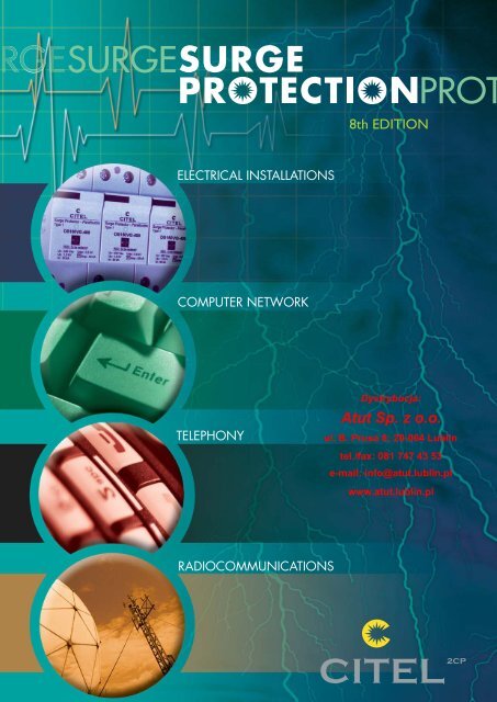
General Catalog8 th editionDIN RAIL <strong>AC</strong> POWER SURGE PROTECTORS<strong>AC</strong> POWER SURGE PROTECTORST ELEPHONE AND DATA LINEH IGH FREQUENCY COAXIALG AS DISCHARGE TUBEM ISCELLANEOUSDystrybucja:Atut <strong>Sp</strong>. z o.o ul. B. Prusa 8, 20-064 LUBLINtel./fax: 081 747 43 53e-mail: info@atut.lublin.plFebruary 2008 - This document could be modified without notice.
An international networkFranceSèvres : - Headquarters- General management- Administrative and Financial Department- Sales division : France and Export- Research and DevelopmentReims - Production and ShipmentSubsidiariesCitel Electronics GmbH - Bochum (Germany)Citel Inc. - Miami (USA)Shanghai Citel Electronics Co., Ltd - Shanghai (China)DistributorsIn more than 50 countriesDystrybucja:Atut <strong>Sp</strong>. z o.o ul. B. Prusa 8, 20-064 LUBLINtel./fax: 081 747 43 53e-mail: info@atut.lublin.pl
A long history......1937 CITEL founded.Manufacture of tubular light bulbs.1944 Manufacture of the first <strong>Surge</strong> Arrester.1976 CITEL acquired by the present Management.Light bulb manufacture discontinued.1978 CITEL gas tubes approved for ALCATEL electronic telecom exchanges.1985 CITEL America founded in Miami.1988 CITEL Electronics GmbH founded in Düsseldorf.1992 Acquisition of the CLAUDE gas tube line from GTE Sylvania.1996 Acquisition of SUPERSAFE in the Netherlands.1996 Founding of Shanghaï CITEL Electronics Co., Ltd.1998 CITEL listed on the Paris Stock Exchange.1999 New Headquarters in Issy les Moulineaux2000 New technology for <strong>AC</strong> surge protectors (VG series).2005 New JV for coaxial surge protectors production CITEL Tong Da).2007 <strong>AC</strong> surge protectors become the best-selling range2008 New Headquaters in Sèvres.The specialist inovervoltage protectionCITEL’s only business is protecting networks and equipment from transientovervoltages, in particular those induced by lightning. For this, CITELmanufactures two complementary basic products:- Gas discharge tubes (or GDTs) are the basic passive componentsused to protect telephone exchanges and equipment from voltage surges;they are generally installed on telephone networks by telecommunicationsoperators.- <strong>Surge</strong> Protection Devices (or SPDs) are units combining severalprotection components. They may be used by the installer or by the endcustomer. They are designed to be incorporated in an installation to protectall electric, electronic, and data-processing equipment from transientovervoltages.
Transient overvoltagesThe users of electronic equipment and telephone and data-processingsystems must face the problem of keeping this equipment in operationin spite of the transient overvoltages induced by lightning.There are several reasons:Integration of electronic components makes the equipment more vulnerable.Interruptions of service are unacceptable.Data transmission networks cover large areas and are exposedto more disturbances.The origin of overvoltagesTransient overvoltages have four main causes :LightningIndustrial and switching surgesElectrostatic discharges (ESD)Nuclear electromagnetic pulses (NEMP)The overvoltages of different origins differ in amplitude, energy, waveform,and recurrence rate.Lightning and industrial overvoltages have been with us for a long time, butESD and NEMP disturbances are much more specific and arise from recenttechnological developments (massive use of semiconductors for the former,thermonuclear weapons for the latter).LightningLightning, investigated since Benjamin Franklin’s first research in 1749, hasparadoxically become a growing threat to our highly electronic society.Lightning formationA lightning flash is generated between two zones of opposite charge, typicallybetween two storm clouds or between one cloud and the ground.The flash may travel several miles, advancing toward the ground in successiveleaps: the leader creates a highly ionized channel. When it reaches theground, the real flash or return stroke takes place.A current in the tens of thousands of Amperes will then travel from ground tocloud or vice versa via the ionized channel.Direct effectsAt the moment of discharge there is an impulse current flow that ranges from1,000 to 200,000 Amperes peak, with a rise time of about few microseconds.This direct effect is a small factor in damage to electric and electronic systems,because it is highly localized.The best protection is still the classic lightning rod or Lightning Protection System(LPS), designed to capture the discharge current and conduct it to a particularpoint.
Indirect effectsThere are three types of indirect electrical effects :Impact on overhead linesSuch lines are very exposed and may be struck directly by lightning, which willfirst partially or completely destroy the cables, then cause high surge voltagesthat travel naturally along the conductors to line-connected equipment. Theextent of the damage depends on the distance between the strike and theequipment.Rise in ground potentialThe flow of lightning in the ground causes earth potential increases that varyaccording to the current intensity and the local earth impedance. In an installationthat may be connected to several grounds (e.g. a link between buildings),a strike will cause a very large potential difference and equipment connectedto the affected networks will be destroyed or severely disrupted.Electromagnetic radiationThe flash may be regarded as an antenna several miles high carrying an impulsecurrent of several tenth of kilo-amperes, radiating intense electromagneticfields (several kV/m at more than 1 km).These fields induce strong voltages and currents in lines near or on equipment.The values depend on the distance from the flash and the properties of thelink.Impact onoverhead linesIndustrial surgesCoupling byradiationAffected networkor equipmentRise in groundpotentialThis term covers phenomena caused by switching electric <strong>power</strong> sources onor off.Industrial surges are caused by:Starting motors or transformersNeon and sodium light startersSwitching <strong>power</strong> networksSwitch «bounce» in an inductive circuitOperation of fuses and circuit-breakersFalling <strong>power</strong> lines...These phenomena generate transients of several kV with rise times in the orderof a few microseconds, disturbing equipment in networks to which the sourceof disturbance is connected.Electrostatic overvoltages (ESD)Electrically, a human being has a capacitance ranging from 100 to 300 picofarads,and can pick up a charge of as much as 15kV by walking on a carpet,then touch some conducting object and be discharged in a few nanoseconds,with a current of about ten Amperes. All integrated circuits (CMOS, etc.) arequite vulnerable to this kind of disturbance, which is generally eliminated byshielding and grounding.NEMP phenomena(Nuclear ElectroMagnetic Pulses)A high-altitude nuclear explosion, above the atmosphere, creates an intenseelectromagnetic field (up to 50 kV/m in 10ns), radiated to a ground area upto 1200 kilometers in radius.In the ground, the field induces very large transient overvoltages in <strong>power</strong> andtransmission lines, antennas, etc., destroying the terminal equipment (<strong>power</strong>circuit, computer terminals, telephone equipment, etc.).The field rise may reach several kV/ns. While it is difficult to eliminate allovervoltages induced by an electromagnetic pulse, there are ways to reducethem and strengthen the systems to be protected. In spite of the amplitude ofthe phenomenon, protection can be provided by shielding and filtering/surgeprotection adapted to NEMP.Effects of overvoltagesOvervoltages have many types of effects on electronic equipment; in order ofdecreasing importance:DestructionVoltage breakdown of semiconductor junctionsDestruction of bonding of componentsDestruction of traces of PCBs or contactsDestruction of triacs/thyristors by dV/dt.Interference with operationRandom operation of latches, thyristors, and triacsErasure of memoryProgram errors or crashesData and transmission errorsPremature ageingComponents exposed to overvoltages have a shorter life.<strong>Surge</strong> Protection devicesThe <strong>Surge</strong> Protection Devices (or SPD : this is a generic name for any deviceto protect from voltage surges) is a recognized and effective solution for theovervoltage problem. For greatest effectiveness, however, it must be chosenaccording to the risk and installed in accordance with the applicable standards.StandardsBecause of the diversity and importance of transients, standards organizationshave created specifications for testing the effects of overvoltages on equipment.The phenomena were first characterized and a series of standardized wavescreated (1.2/50μs voltage wave and 8/20μs and 10/350μs current waveforms),then a number of standards defining surge arrester performance wereissued, among them :<strong>Surge</strong> <strong>Protectors</strong> for Low-Voltage installations :NF EN 61643-11 (France)EN 61643-11 (Europe)UL 1449 (USA)IEC 61643-1 (International)<strong>Surge</strong> <strong>Protectors</strong> for Telecom equipment :IEC 61643-21 (International)ITU-T recommendations K11, K12, K17, K20, K21, K36 (International)UL 497 A/B (USA)
A1M ODULAR<strong>AC</strong> POWERS URGE PROTECTORSM O D U L A R A C P O W E RS U R G E P R O T E C T O R S
Din Rail <strong>AC</strong> Power <strong>Surge</strong> <strong>Protectors</strong>A2DS <strong>Surge</strong> <strong>Protectors</strong>CITEL DS <strong>AC</strong> <strong>power</strong> <strong>Surge</strong> Protective Devices (SPD) are designed to meetall surge protection needs for low voltage installations.Designed for mounting on DIN rails, these protectors are easy to install instandardized panels and cabinets and are equipped with thermal disconnectiondevices and indicators allowing total operating safety.DS surge protectors are available with several protection diagrams to complywith different installation needs and standard requirements.CITEL <strong>AC</strong> <strong>power</strong> surge protectors offer three levels of surge protection correspondingto different IEC or EN classes.StandardsTo ensure efficient and reliable performances, all CITEL’s <strong>AC</strong> <strong>power</strong> surgeprotectors comply with the leading standards.Relevant standards in the <strong>AC</strong> surge protection field could be split into 3types of documents :«Product» standards :These documents address the type of tests the SPD manufacturer mustapply on its devices :- Europe : EN 61643-11- International : IEC 61643-1- USA : UL1449-2ed- France : NF EN 61643-11«Selection» standards :They define the basic rules to select the surge protector in accordance withthe general electrical code :- Germany : DIN VDE 0100 part 443 and 534- International : IEC 60364-4-433 and 5-534- France : NF C 15-100 sect. 443 and 534Operating principleDS surge protectors are based on zinc metal-oxide varistors (MOV), thebest compromise between a fast response time (
VG technology by CITELIn order to improve the surge protection efficiency, CITEL has developed apatented technology which combines high energy varistor (MOV) networkand specific gas tube (GDT) : by this way, the «VG» Type 1 surge protectors(DS150VG, DS250VG, DUT250VG) can get higher performances in :- Protection level,- Life duration (due to the suppression of leakage current),- Continuous operation and <strong>power</strong> quality (no follow current)- End of life behaviour.For instance, these features allow it to reach, even with a single stage ofsurge protection, the same protection efficiency as a double stage association(Type 1 + Type 2 SPDs).Residual voltage - UresThis parameter is the residual voltage across the SPD terminal during theinjection of a selected impulse current. It may be lower than the protectionlevel Up, for surge protectors like «VG» series.Type of surge protectorsThe <strong>AC</strong> <strong>power</strong> surge protectors are split into 3 categories by IEC 61643-1and EN 61643-11 standards, with the following 3 classes of tests. Thesedifferent tests depend on the location of the surge protector in the <strong>AC</strong>network and on the external conditions.A3<strong>Surge</strong> protectors parameters<strong>Surge</strong> protectors are defined by a series of electrical specifications whichwill help the user to select the right protection specific to their installation:Operating voltage - UcThe maximum continuous operating voltage (MCOV) Uc is the maximumr.m.s voltage which may be applied continuously to the SPD.Temporary overvoltage - U TThe temporary overvoltage U T (TOV) is the maximum r.m.s. value the surgeprotector can withstand during 5 seconds, without failure. In many cases ,this parameter U T is equal to Uc.Discharge current - In and ImaxThe maximum discharge current (Imax), applicable to Type 2 SPD, is themaximum impulse current 8/20 μs a surge protector can withstand withoutdestruction .The nominal discharge current (In) is the level of impulse current a surgeprotector Type 1 or Type 2 can withstand repeatedly (15 surges) withoutdestruction.Impulse current - IimpThe impulse current (Iimp), used in Class I test applicable to Type 1 SPDs,is the maximum impulse 10/350 μs current a surge protector can withstandwithout destruction. This test simulates the effect, on <strong>AC</strong> <strong>power</strong> surge protectors,of a direct lightning strike on an installation.Type 1 <strong>Surge</strong> <strong>Protectors</strong>Type 1 surge protectors are designed to be installed where a direct lightningstrike risk is high, especially when the building is equipped with externallightning protection system (LPS or lightning rod). In this situation,EN 61643-11 and IEC 61643-1 standards require the Class I test to beapplied to surge protectors : this test is characterized by the injection of10/350 μs impulse current in order to simulate the direct lightning strikeconsequence. Therefore these Type 1 surge protectors must be especially<strong>power</strong>ful to conduct this high energy impulse current.Type 1SPDDifferent SPD typesfollowing IEC and EN standardsORDS250DS150Type 2SPDDS70RDS40Type 2 (or Type 3)SPDDS10DS210DOpen circuit voltage - UocThis parameter is used only for Class III test, applicable to Type 3 SPD andconsists of the injection of a combination wave (1.2/50 μs in open circuit- 8/20 μs in short circuit).Protection level - UpThis is the maximum voltage on the surge protector output when subjectedto an impulse current equivalent to its nominal discharge current(In). Therefore this parameter characterizes the performance of the SPDin limiting the transient overvoltage across its terminal in order to protectthe equipment.
Din Rail <strong>AC</strong> <strong>power</strong> <strong>Surge</strong> <strong>Protectors</strong>A4Type 2 surge protectorsType 2 surge protectors are designed to be installed at the beginning ofthe installation, in the main switchboard, or close to sensitive terminals, oninstallations without LPS (lightning rods). These protectors are tested followingthe Class II test from IEC61643-11 or EN61643-11standards andbased on 8/20 μs impulse current injection.Type 3 surge protectorsIn case of very sensitive or remote equipment, secondary stage of surgeprotectors is required : these low energy SPDs could be Type 2 or Type 3.Type 3 SPDs are tested with a combination waveform (1,2/50 μs - 8/20μs) following Class III test.Disconnection devicesIn compliance with the standards, the <strong>AC</strong> <strong>power</strong> surge protectors areequipped with external and internal disconnection devices in order to providetotal safety in case of failure.2 types of devices are necessary :- Internal thermal security which will disconnect the surge protector fromthe <strong>AC</strong> network in case of thermal runaway. In such a case, the user will bewarned about the trouble by an indicator (mechanical or light) in front ofthe protector and will carry out the replacement of the defective SPD.Remote SignalingMost DS surge protectors are available in «remote signaling» versions. Thisfeature, which allows remote checking of the status of the surge protector,is especially important when the products are hard to reach or unsupervised.The system consists of an auxiliary changeover contact that is activated ifthe surge protector module changes status.This lets the user monitor :- the good operation of the SPD- the presence of the plug-in modules (if any)- the end of life (disconnection) of the surge protector.The remote signaling version allows the choice of signaling system appropriateto the installation (light, buzzer, automation, modem transmission...).Pluggable designThe design of some DS surge protectors (DS10, DS40, DS70R...) is basedon the use of a pluggable module that plugs into a matching receptacle.This makes replacement, and checking very easy without impairing the protectionfunction. On multipolar surge protectors, the possibility of replacinga single pole makes rehabilitating a surge protector less expensive.The plug-in module is identified with a color label in relation with the type(Black = Type 1 ; Red = Type 2 ; Blue = Type 2 low <strong>power</strong> or Type 3) andare keying for operating voltage, in order to avoid misapplications.<strong>AC</strong> <strong>power</strong> <strong>Surge</strong> Protector DS40- External electrical disconnection (fuses or breaker) to disconnect thesurge protector from the <strong>AC</strong> network in case of internal short circuit, e.g.due to an excessive impulse current. The rating of the external fuses (orbreaker) are in relation with the discharge capability of the SPD and theprospective short-circuit current of the installation. To ease the selection ofthese components, the rating and type of fuses (or breaker) is mentionedin the SPD instructions by the manufacturer.Note : even if standards require safety devices, the risk of disconnection of the surgeprotectors is very low.MaintenanceDS surge protectors are designed for repetitive operation and do not requirespecific maintenance. Nevertheless, in case of an extreme event, acontrolled end of life could occur (see above) and a maintenance operationmust be performed .SignalingDS surge protectors are equipped with a failure indicator (mechanical orlight) linked to the internal thermal disconnector : in case of safety disconnection,the indicator will switch on and the SPD must be replaced..ConnectionConductor or BusMarkingVoltagekeyingDIN mountingDin rail formatIdentification of versionSafety remotesignalingBuilt-indisconnectorsIndicatorsPluggable
<strong>Surge</strong> protection installationLocationDS surge protectors are installed as follows, according to their types :- Type 1 or «Heavy duty» : at the origin of the installation, in a separatebox or on the main electrical panel, for efficient discharge of high lightningcurrents.- Type 2 or «Primary» : at the origin of the installation, on the main electricalpanel, so as to shunt lightning currents as directly as possible andthereby avoid coupling.- Type 2 (or Type 3) or «Secondary» : on the secondary panel, near thesensitive equipment, to limit ringing and improve the level of protection.WiringSince lightning surges are essentially common-mode phenomena, DSsurge protectors are connected mainly in the common mode (between theactive conductors and ground).Some recommendations call for additional differential-mode protection(between phase and neutral). For this case, CITEL proposes special surgeprotectors (types DUT40, DS210D...) or, when the standards allow, combinationsof surge protectors between phases and neutral (differential mode)with a special surge protector (DS100EG, DS40G) between neutral andground (common mode) : this type of mounting, named «CT2 connection»in IEC 60364 standard, is used in surge protectors such as DS44-230/G.InstallationDS surge protectors are connected in parallel on the <strong>AC</strong> network and mustbe equipped with external fuses (or breakers) for short-circuit protection(see paragraph «Disconnection devices»).- The total length of connection wires to <strong>AC</strong> network must be lower than0.5 m in order not to increase the protection level (Up) provided by theSPD.- Wiring is made by screw connections. On some models, a distributionbus can be used.- The protection wire coming from the SPD must be connected to the bondingbar of the electrical panel. Paralleling the protection wire with phasesconductors must be avoided.- The cross sectional wire must be 4 mm² minimum for Type 2 SPD’s and10 mm² for Type 1.- Local earthing resistance must be in compliance with the electrical rules.Further information can be found in IEC 61643-12 standard (selection andapplication principles for low voltage SPD).Installation example (Type 2 surge protector DS44S)<strong>AC</strong> networkType «S» or delayedground fault breakerInstallationA5Protection modesCommon mode protectionCT1 ConnectionL1L2L3NDS44-400PFDisconnectioncheck lightFuses orcircuit-breaker3-Phasesurge protectorDS44S-400Mainearthingbarto groundnetworktotal length ofthe conductor< 0,5 mCommon and differential mode protectionCT2 ConnectionL1L2L3NFPDS44-230/G
Din Rail Low Voltage <strong>Surge</strong> <strong>Protectors</strong>A6Choosing <strong>Surge</strong> <strong>Protectors</strong>CITEL’s line of <strong>AC</strong> <strong>power</strong> surge protectors is designed to cover all possibleconfigurations in low voltage installations.They are available in many versions, which differ in :- Type or test class (1 , 2 or 3)- Operating voltage (Uc)- <strong>AC</strong> network configuration (Single/3-Phase)- Discharge currents (Iimp, Imax, In)- Protection level (Up)- Protection technology (varistors, gas tube-varistor, filter)- Features (differential mode, plug-in, remote signaling...).The surge protection selection must be done following the local electricalcode requirements (e.g. : minimum rating for In) and specific conditions(e.g. : high lightning density).Choosing the Type of surge protectorsThis choice is in relation to the LPS condition (Lightning Protection System)and the SPD location in the installation.Configuration SPD Location CITELInstallation equippedwith LPS or could be hitby lightningType 1Origin of theinstallation origin(Panel or mainswitchboard)DS150DS250DUT250VGDUM125Installation without LPS Type 2 main switchboard DS70R, DS40DS240,DUT40Secondary protection(downstream primarySPD)Type 2(or Type 3)close to protectedequipmentDS10DS215DUT10Choosing of the operating voltage UcThe SPD Uc voltage (maximum continuous operating voltage) dependson:- Nominal voltage of the <strong>AC</strong> network (Uo)- Level of possible temporary overvoltages (TOV) U T- Type of <strong>AC</strong> system (TN, TT, IT).Operating voltage Uc (Line/Ground)<strong>AC</strong> Network 230/400V 120/208V<strong>AC</strong> system TT TN IT TNVoltage Uc 255 V 255 V 400 V 150 VVoltage U T 400 V 335 V - -Example ofCITEL productDS42-400DS42-320 orDS42-400DS42-400DS42-120<strong>AC</strong> network configurationDS surge protectors are available for single, 3-Phase and 3-Phase + neutral<strong>AC</strong> networks.Choosing IimpThe impulse current Iimp is defined for Type 1 SPD. The minimum rating forIimp is 12.5 kA by pole, following IEC 60364-5-534 . This level is adaptedto the real phenomenon.CITEL proposes, in its Type 1 SPD range, 2 levels of Iimp current : 15 and25 kA.Configuration Iimp CITELVery high lightning densityBad earthingHigh, meduim or low lightningdensity25 kA DS250EDS250VGDUT250VG15 kA DS150EDS150VGChoosing In and Imax currentsThe relevant nominal discharge current In for the SPD is in relation with thelightning risk in the installation area.The minimum rating of In for a SPD connected at the installation entranceis 5 kA (8/20 μs waveform), required by standard.Nevertheless higher ratings are advised in case of high lightning density.Moreover higher values of In current will increase the SPD lifetime.Imax (max. discharge current) rating is linked to In .Conditions In CITELVery high lightning density > 20 kA DS70RHigh or medium lightning density 10-20 kA DS40DS240Low lightning densityor secondary SPD5 kA DS10DS215Choosing the protection level UpThe user must select a surge protector with a protection level Up adaptedto the withstand level of terminal equipment. In every case, the lower theprotection level Up, the better the protection.IEC 60364 standard calls for the minimum protection level of 2.5 kV fora SPD connected at the entrance of a 230/400 V network : this level is incompliance with the withstand of robust devices (electromechanical type).Electronic-based terminals have lower impulse withstand and require abetter protection : so, surge protectors with 1.5 kV protection are necessaryto provide efficient protection.ConditionsRecommended Up230/400 V<strong>AC</strong> network120/208 V<strong>AC</strong> networkSPD at the installation entrance 2.5 kV max. 1.5 kV max.Electromechanical protected equipment 2.5 kV 1.5 kVElectronic-based protected equipment 1.5 kV 0.8 kVA relevant choice of the SPD technology, as well as the use of coordinationdiagram can help to improve the protection level.
Choosing the SPD technologyDS surge protectors are based on Varistor (MOV) technology. Some versionsuse different electrical diagrams :- «VG» technology : this Gas tube-Varistor hybrib association, used in Type1 SPD (DS150VG, DS250VG, DUT250VG), improves the protection levelUp and the residual voltage Ures.- Association with RFI filter : The <strong>Surge</strong> protection panel CBB and secondarySPD DS-HF combine surge protection stage and filter stage in orderto improve the protection level.Coordination by conductorL1L2 < 10 mPhP2P3A7Coordination of <strong>Surge</strong> <strong>Protectors</strong>In order to provide maximum protection efficiency, it is necessary to createa «coordination» diagram, that means installation of a «primary» SPD atthe network entrance and a «secondary» close to sensitive equipment.This association is required in the 2 following cases :- High sensitivity equipment :Improvement of protection level.- Long distance (greater than 30 m) of wire between equipment to beprotected and primary SPD :Reduction of ringing voltages created during the surge transmission.Coordination by inductorPhP2LP3L2 < 10 mP2 : Primary surge protector (ex. DS40)P3 : Seconadary surge protector (ex. DS215/G)L : Coordination inductors (ex. DSH35)L1 : Length of conductor between surge protectorL2 : Length of conductor between surge protector and installationEfficient SPD coordination is performed by including between primary andsecondary SPDs :- a minimum length of wire (> 10 m).or- a coordination inductor (DSH range).
International Standards for <strong>AC</strong> <strong>Surge</strong> ProtectionA8The performance, selection and application of <strong>AC</strong> surge protectors aredefined by standards, to ensure an efficient and secure use.National standards are often based on IEC international standards. In thefield of <strong>AC</strong> surge protection, several documents must be taken into consideration.Standards in surge protectionRelated standards for test performance, selection and application of lowvoltage SPDs are :General rules : IEC 60364 standard :- Section 4-443 : «Protection against overvoltages of atmospheric originor due to switching» :This section of IEC 60364 is intended to describe the means by whichtransient overvoltages can be limited to reduce the risk of failures inthe installation, and in electrical equipment connected to it, to an acceptablelevel.- Section 5-534 : «Devices for protection against overvoltages» :This section gives the basic requirements for the selection and implementationof the SPDs for electrical installation of buildings to obtaina limitation of transient overvoltages.Product standard : IEC 61643-1 :This document addresses performance tests for <strong>AC</strong> surge protective devices(SPDs) following different classes (Class I , II or III test). It is mainlydedicated to surge protector manufacturersSelection and application guide : IEC 61643-12 :This guide addresses the selection and application principles of SPDs inpractical situations.The section 4-443 of IEC 60364 recommends SPDs on electrical installationsif they are supplied by overhead lines (partially or totally) and if thelocal keraunic level is equal or greater than 25. Some national standardsbased on IEC make the SPD installation mandatory in these conditions.3 - The installation is connected to an overhead <strong>AC</strong> network and the localkeraunic level Nk ≤ 25 (or the lightning density Ng ≤ 2.5) :<strong>Surge</strong> Protector not required.4 - The installation is connected to an underground <strong>AC</strong> network<strong>Surge</strong> Protector not required.Nevertheless, in the two last cases, a more accurate analysis could bedone, taking into account the type of equipment (sensitivity, cost..) or theconsequences of a service interruption (downtime costs, human hazards...): IEC 61662 international standard proposes a method for assessing therisk related to surges due to lightning.5 - The unavailability of the electrical network could have consequenceson human safety.<strong>Surge</strong> Protector mandatory or risk analysis required.Application of the <strong>AC</strong> surge protectors following IEC 60364Type of installation Nk < 25 Nk > 25Installation equipped with directlightning protection system (LPS)Connection to overhead <strong>AC</strong> lineConnection to underground <strong>AC</strong> lineThe unavailabalitiy of the electricalnetwork could have consequences onhuman safetyMandatory(Type 1)Nomandatory*Nonmandatory*Risk analysisrequiredMandatory(Type 1)Mandatory(Type 2)Nonmandatory*Mandatory(*) <strong>Surge</strong> protectors are recommended in case of sensitive equipment or when areinforced reliability is required.ConclusionDepending on the countries, <strong>AC</strong> surge protectors could be recommendedor mandatory in relation with the external conditions (type of network andlightning threat). Risk assessment methods are also available to determinemore accurately the need of surge protection. In any case, all the presentelectrical installations are crowded with sensitive devices, making the useof surge protectors more and more relevant.Recommendations for SPD installationSection 5-534 gives the minimum performance required for SPD installedat the entrance of installation, as nominal discharge current In ≥ 5 kA forType 2 SPD and Lightning current Iimp ≥ 12.5 kA for Type 1 SPD.1 - The installation equipped with lightning rod (LPS):Recommendation : Type 1 SPD, with Lightning impulse currentIimp of 12,5 kA minimum, connected at the origin of the installation.2 - The installation is connected to an overhead <strong>AC</strong> network and the localkeraunic level Nk ≥ 25 (or the lightning density Ng ≥ 2.5) :Recommendation : Type 2 SPD, with nominal discharge currentIn ≥ 5 kA, connected at the origin of the installation.Lightning RisksLow : Nk < 15Medium : 15 < Nk< 25High : Nk > 25Example of keraunic levels (France)La RéunionGuyane/Martinique/GuadeloupeSt Pierre et Miquelon
DS SeriesDS surge protectors are available in single phase and 3-Phase versions.They can be chosen in several configurations : monobloc, multipole, prewiredin panels....VersionsDescriptionImax *(8/20 μs)Iimp *(10/350 μs)Main FeaturesCommentsType 1DS250EDS250VGDS150EDS150VGDS100EG1-pole reinforcedsurge protector1-pole reinforcedsurge protector1-polesurge protector1-pole reinforcedsurge protectorN/PEsurge protector140 kA 25 kA70 kA 25 kA140 kA 15 kA40 kA 15 kA100 kA 50-100kAVery high energyVery high energyLow UpVery high energyVery high energyLow UpVery high energyLow UpType 1 <strong>Surge</strong> protectorsDesigned to be installed where a direct lightningstrike risk is high, especially when the building isequipped with external lightning protection system(LPS). In this situation, EN 61643-11 and IEC61643-1 standards require the Class I test be appliedto surge protectors : this test is characterizedby the injection of 10/350 μs impulse current inorder to simulate the direct lightning strike consequence.Therefore these Type 1 surge protectorsmust be especially <strong>power</strong>ful to conduct this highenergy impulse current.A9DUT250VG3-Phasesurge protector100 kA 25 k<strong>AC</strong>ompactVery high energyDUM1251 and 3-Phasesurge protector100 kA 12.5 k<strong>AC</strong>ompact, High energy,cost effecitveType 2DS70RDS40DS40/G1-pole and multipolarsurge protectors1-pole and multipolarsurge protectorsSingle and 3-Phasesurge protector70 kAPluggable40 kA Pluggable40 kAPluggableCommun/diff. modeType 2 <strong>Surge</strong> protectorsDesigned to be installed at the beginning of the installation,in the main switchboard, or close to sensitiveterminals, on installations without LPS. Theseprotectors are tested following the Class II test fromIEC61643-11 or EN61643-11standards and basedon 8/20 μs impulse current injection.DS240/GSingle phasesurge protector40 kAPluggable, Compact,Common /diff. modeDUT403-Phasesurge protector40 kAMonoblocCommon/diff. mode.Type 2 (or 3)DS10DS10/GDUT10DS215/G1-pole and multipolarsurge protectorSingle and 3-Phasesurge protectors3-Phasesurge protectorSingle phasesurge protector10 kA Pluggable10 kA10 kA15 kAPluggableCommon/Diff Mode.MonoblocCommon/Diff Mode.PluggableCommon/Diff Mode.Type 2 or Type 3 <strong>Surge</strong> protectorsIn case of very sensitive or remote equipment, secondarystage of surge protectors are required :these low energy SPDs could be Type 2 or Type 3.Type 3 SPDs are tested with combination waveform(1,2/50 μs - 8/20 μs) following Class III test.DS-HFSingle phase surgeprotector + filter10 kARFI filterLow UpDS210DC1-pole surgeprotector6 kA PluggableCB..Single and 3-Phasesurge protector panel40-140 kA 15 kA Several diagrams<strong>Surge</strong> protection panels - Type 1 or Type 23 protection diagramsDS..PV<strong>Surge</strong> protectors forphotovoltaic40 kA 12,5 kA from 500 to 1000 VdcType 1 and 2 SPDs for photovoltaic installationDSHCoordinationinductorsNominal currents : 16 A,35 A, 63 and 100 <strong>AC</strong>omponents to connect in series between 2 SPDsin order to insure coordination.* Discharge currents by pole.
DS surge protectors wiringCommon mode protection (CT1connection)Common mode (L/PE) protection provided by DS surge protectors in relation withthe different types of <strong>AC</strong> network. Called CT1 connection type in IEC 60364 std.Type 1 <strong>Surge</strong> Protector1 4Single-phase networkType 2 <strong>Surge</strong> ProtectorSingle-phase networkDiagramA10LNMain swichtboardFFLNMain swichtboardFFLNDFType 1 surgeprotectorDS152 andDS252 seriesRemote signalingof disconnectionPERemote signalingof disconnectionType 2 <strong>Surge</strong>protectorDS70R, DS40and DS10 seriesPEPBusbarGroundGround2Type 1 <strong>Surge</strong> Protector3-Phase network5Type 2 <strong>Surge</strong> Protector3-Phase networkDiagramL1L2L3Type 1 surgeprotectorDS153 andDS253 seriesRemote signalingof disconnectionF F FMain swichtboardPENL1L2L3Remote signalingof disconnectionType 2 surgeprotectorDS70R, DS40and DS10 seriesMain swichtboardF F FPENL1L2L3DPFBusbarGroundGroundL1L2L3NRemote signalingof disconnection3Type 1<strong>Surge</strong> protectorDS154 and DS254seriesType 1 <strong>Surge</strong> Protector3-Phase network + neutralMain swichtboardF F F FPEL1L2L3NRemote signalingof disconnection6Type 2 surgeprotectorDS70R, DS40and DS10 seriesType 2 <strong>Surge</strong> Protector3-Phase network + neutralMain swichtboardF F F FPEL1L2L3NDiagramDPFBusbarGroundGroundP : <strong>Surge</strong> protectorD : Circuit breakerF : Associated disconnector(fuse or circuit-breaker)
DS surge protectors wiringCommon and Differential mode protection (CT2 connection )Common mode (L/PE) and differential mode (L/N) protection provided by DS surge protectors in relationto the different types of <strong>AC</strong> network. These configurations CT2 (following IEC 60364) are also called “1+1” and “3+1” mounting.Type 1 <strong>Surge</strong> Protector7 9Single-phase networkType 2 <strong>Surge</strong> ProtectorSingle-phase networkDiagramL1NType 1 surgeprotectorDS152/G andDS252/GseriesRemote signalingof disconnectionMain swichtboardF FPEL1L2L3NRemote signalingof disconnectionType 2 <strong>Surge</strong>protectorDS42/GDS12/GMain swichtboardFFPELNFPGA11Busbar «1+1»GroundGroundType 1 <strong>Surge</strong> Protector8 103-Phase network + neutralType 2 <strong>Surge</strong> Protector3-Phase network + neutralDiagramL1L2L3NRemote signalingof disconnectionType 1 surgeprotectorDS154/G andDS254/GseriesMain swichtboardF F F FPEL1L2L3NRemote signalingof disconnectionType 2 surgeprotectorDS44/GDS14/GMain swichtboardF F F FPEL1L2L3NDFPGBusbar «3+1»GroundGround11Type 1 <strong>Surge</strong> Protector3-Phase network + neutralDiagramL1L2L3NMain swichtboardF F F FL1L2L3NDFType 1surge protectorDUT250VGPGroundPEP : <strong>Surge</strong> ProtectorG : <strong>Surge</strong> protector with GDTD : Circuit breakerF : Associated disconnector(fuse or circuit-breaker)G
DS surge protectors wiringMultipole Type 2 surge protectors wiringWiring instructions for Multipole Type 2 surge protectors.12Type 2 surge protector + FilterSingle phase networkDiagramA12LNLNPRFIType 2 <strong>Surge</strong>protector-filterDS-HFDS-HFPEGround13Type 2 <strong>Surge</strong> protectorSingle-phase networkDiagramN LLNFFFFRemote signalingof disconnectionPType 2 <strong>Surge</strong>protectorDS240/GDS215/GDS240/GPEGround14Type 2 <strong>Surge</strong> protector3-Phase network + neutralDiagramNL1L2L3FF F FL1L2L3NDFPType 2 <strong>Surge</strong>ProtectorDUT40DUT10DUTPEGroundP : <strong>Surge</strong> protectorRFI : RFI filterD : BreakerF : Associated disconnector(fuse or circuit-breaker)
DS surge protectors wiringCoordination of <strong>Surge</strong> ProtectorIn order to provide maximum protection efficiency, it is necessary to createa «coordination» diagram: that means installation of a «primary» SPD atthe network entrance and a «secondary» close to sensitive equipment.Efficient SPD coordination is performed by including, between primary andsecondary SPDs :- a minimum length of wire (> 10 m).or- coordination inductors (DSH range: see below).Futher information is available in installation instruction sheet.A13Example of coordination on 3-Phase network.L1L2L3NTGBTF F F FF F F FType 1 <strong>Surge</strong>protectorDS150 andDS250 seriesType 2 surgeprotectorDS70R andDS40 seriesPECoordination inductorsPEGroundDiagramL1L2L3NDPFLFPP : <strong>Surge</strong> protectorD : BreakerF : Associated disconnector(fuse or circuit-breaker)L : Coordination inductor
DS surge protectors wiringA14Associated fusesTo comply with standards and safety, the <strong>AC</strong> surge protectors must be protectedagainst a possible end of life in short-circuit : the user must installon each SPD branch, a protection against short circuit current (fuses orbreaker).The rating of this fuse is given by the SPD manufacturer in the productdatasheet and installation instructions. The choice of this rating dependsof 2 criteria:- Withstand of the short-circuit current test in the IEC 61643-1standard : the fuse must cut safely the short-circuit current beforean harsh destruction of the SPD.- Withstand of the discharge currents (In or Imax) : the fuse mustbe able to conduct the discharge current of the SPD without blowing.Fuses on eachbranch, rating andtype in the SPD installationinstructions.CITEL has selected some fuses and DIN rail holders to fit with his SPDrange. The fuses are equipped with failure indicators to check easily theiropening and the holders can be supplied with or without contact for remotesignal of fuse status.Fuses for SPDRating Dimensions Fuse P/N125 A gG 22x58 mm 6062 0125100 A gG 22x58 mm 6062 010050 A gG 22x58 mm 6062 005020 A gG 22x58 mm 6062 0020Fuse holdersNumber of poleswith remotesignaling contactwithou remotesignaling contact1 pole 5603 5012 5603 50022 poles 5603 5013 5603 50033 poles 5603 5014 5603 50044 poles 5603 5016 5603 5006
Type 1 <strong>Surge</strong> ProtectorNetworkvoltage DS250VG DS150VG DS250E DS150E DUT250VG DUM125 Protection ModeType ofNetworkNeutralconfiguration230/400 V DS250VG-300 DS150VG-300 DS250E-300 DS150E-300 - - Common Mode Uniphase 230 V - -- DS150VG-400 DS250E-400 DS150E-400 - - Common Mode Uniphase 400 V - -- DS152VG-400 DS252E-400 DS152E-400 - DUM125-400 Common Mode Single phase TT - TN - IT 1DS252VG-300 DS152VG-300 DS252E-300 DS152E-300 - DUM125-400 Common Mode Single phase TNS 1DS252VG-300/G DS152VG-300/G DS252E-300/G DS152E-300/G - - Common and Differential Mode Single phase TT - TNS 7DS253VG-300 DS153VG-300 DS253E-300 DS153E-300 - - Common Mode 3-phase TNC 2- DS153VG-400 DS253E-400 DS153E-400 - - Common Mode 3-phase TNC - IT 2- DS154VG-400 DS254E-400 DS154E-400 - DUT125-400 Common Mode 3-phase + N TT - TN - IT 3DS254VG-300 DS154VG-300 DS254E-300 DS154E-300 - DUT125-400 Common Mode 3-phase + N TNS 3DS254VG-300/G DS154VG-300/G DS254E-300/G DS154E-300/G DUT250VG-300/G - Common and Differential Mode 3-phase + N TT - TNS 8120/208 V DS250VG-120 DS150VG-120 DS250E-120 DS150E-120 - - Common Mode Uniphasé 120 V - -DS252VG-120 DS152VG-120 DS252E-120 DS152E-120 - - Common Mode Single phase TNS 1DS252VG-120/G DS152VG-120/G DS252E-120/G DS152E-120/G - - Common and Differential Mode Single phase TT - TNS 7DS253VG-120 DS153VG-120 DS253E-120 DS153E-120 - - Common Mode 3-phase TNC 2DS254VG-120 DS154VG-120 DS254E-120 DS154E-120 - - Common Mode 3-phase + N TNS 3DS254VG-120/G DS154VG-120/G DS254E-120/G DS154E-120/G - - Common and Differential Mode 3-phase + N TNS 8Diagram(pagesA10-A12)A15Type 2 <strong>Surge</strong> ProtectorNetworkvoltage DS70R DS40 DS10 Protection Mode Type of NetworkNeutralconfigurationDiagram(pages A10-A12))230/400 V DS71R-230 DS41-230 DS11-230 Common Mode Uniphase 230 V - -DS71R-400 DS41-400 DS11-400 Common Mode Uniphase 400 V - -DS72R-400 DS42-400 DS12-400 Common Mode Single phase TT - TN - IT 4DS72R-230 DS42-230 DS12-230 Common Mode Single phase TNS 4- DS42-230/G DS12-230/G Common and Differential Mode Single phase TT - TN 9DS73R-230 DS43-230 DS13-230 Common Mode 3-phase TNC 5DS73R-400 DS43-400 DS13-400 Common Mode 3-phase TNC - IT 5DS74R-400 DS44-400 DS14-400 Common Mode 3-phase + N TT - TN - IT 6DS74R-230 DS44-230 DS14-230 Common Mode 3-phase + N TNS 6- DS44-230/G DS14-230/G Common and Differential Mode 3-phase + N TT - TNS 10120/208 V DS71R-120 DS41-120 DS11-120 Common Mode Uniphasé 120 V - -DS72R-120 DS42-120 DS12-120 Common Mode Single phase TNS 4- DS42-120/G DS12-120/G Common and Differential Mode Single phase TT - TNS 9DS73R-120 DS43-120 DS13-120 Common Mode 3-phase TNC 5DS74R-120 DS44-120 DS14-120 Common Mode 3-phase + N TNS 6- DS44-120/G DS14-120/G Common and Differential Mode 3-phase + N TNS 10Accessories DSM70R-400 DSM40-400 DSM10-400 Plug-in 400 V module - - -DSM70R-230 DSM40-230 DSM10-230 Plug-in 230 V module - - -DSM70R-120 DSM40-120 DSM10-120 Plug-in 120 V module - - -DSB12-400 DSB1-400 DSB1-400 Base for 1 module 400 V - - -DSB12-230 DSB1-230 DSB1-230 Base for 1 module 230 V - - -DSB12-120 DSB1-120 DSB1-120 Base for 1 module 120 V - - -DSB12-S2-400 DSB1-S1-400 DSB1-S1-400 Base for 1 module 400V + remote signal - - -DSB12-S2-230 DSB1-S1-230 DSB1-S1-230 Base for 1 module 230V + remote signal - - -DSB12-S2-120 DSB1-S1-120 DSB1-S1-120 Base for 1 module 120V + remote signal - - -Type 2 (or Type 3) <strong>Surge</strong> ProtectorNetworkvoltageDUT40DUM40DS240DUT10DUM10DS215 DS-HF Protection ModeType ofNetworkNeutralconfigurationDiagram(page A12)230/400 V - DS240-400 - DS215-400 - Common Mode Single phase TT - TN - IT 13DUM40-230/G DS240-230/G DUM10-230/G DS215-230/G DS-HF Common and Differential Mode Single phase TT - TN 13/12- DS240-230 - DS215-400 - Common Mode Single phase TNS 13DUT40-230/G DS240-230/G DUM10-230/G DS215-230/G - Common and Differential Mode Single phase TNS 13DUT40-230/G - DUT10-230/G - - Common and Differential Mode 3-phase TT - TNS 14- 2 x DS240-400 - 2 x DS215-400 - Common Mode 3-phase + N TT - TNS - IT -DUT40-230/G - DUT10-230/G - - Common and Differential Mode 3-phase + N TT - TNS 14120/208 V DUM40-120/G DS240-120 DUM10-120/G DS215-120 DS-HF-120 Common (and Differential) Mode Single phase TT - TNS 13/12DUT40-120/G 2 x DS240-120 DUT10-120/G 2 x DS215-120 - Common (and Differential) Mode 3-phase + N TT - TNS 13Accessoires - DSM240-400 - DSM215-400 - Plug-in 400 V module - - -- DSM240-230 - DSM215-230 - Plug-in 230 V module - - -- DSM240-120 - DSM215-120 - Plug-in 120 V module - - -- DSB2-400 - DSB2-400 - Base for 1 module 400 V - - -- DSB2-230 - DSB2-230 - Base for 1 module 230 V - - -- DSB2-120 - DSB2-120 - Base for 1 module 120 V - - -- DSB2-S2-400 - DSB2-S2-400 - Base for 1 module 400V + remote signal - - -- DSB2-S2-230 - DSB2-S2-230 - Base for 1 module 230V + remote signal - - -- DSB2-S2-120 - DSB2-S2-120 - Base for 1 module 120V + remote signal - - -
Type 1 <strong>AC</strong> <strong>power</strong> <strong>Surge</strong> ProtectorDS250VGDimensions and DiagramIimp25 kA67 36A16909The DS250VG is a Extreme Duty Type 1 <strong>AC</strong> <strong>Surge</strong> Protector Device(SPD) designed to be connected at the entrance of the electricalinstallation. This SPD provides an efficient protection against directand indirect effects and is particularly useful in a high lightning densityarea where the risk of heavy surge current or even direct strike ishigh (e.g. : buildings equipped with lightning rods).The DS250VG is a one-pole SPD and can be used in commonmode (2, 3 or 4 DS250VGs connected between L/PE and N/PE =CT1 configuration) or common and differential mode (DS250VGsconnected between L/N and 1 x DS100G between N/PE = CT2configuration). See pages A20 and A21.This SPD is designed to withstand a 25 kA lightning current (10/350μs impulse). It is based on specific heavy duty GDT and high energyMOV block : this technology allows the best behaviour possible onthe <strong>AC</strong> network (no follow current and no leakage current) and avery low residual voltage.The SPD is DIN rail compatible and is featured with a double terminalfor line wire to allow improved connection to the <strong>AC</strong> network.To meet standards, the DS250VG includes a thermal disconnectionmechanism, fault indicator and an internal microswitch for remotesignaling.Type 1 <strong>Surge</strong> protector25 kA on 10/350 μs impulseLow voltage UpInternal disconnection, status indicatorand remote signalingIEC 61643-1 and EN 61643-11 complianceUL 1449 ed. 2 recognitiont oLinFtLoutCharacteristicsGVCMIV : High energy varistor networkG : Heavy duty gas TubeFt : Thermal fuseC : Remote signaling contactt° : Thermal disconnection systemMI : Disconnection indicatorCITEL part number DS250VG-300 DS250VG-120<strong>AC</strong> Network 230/400V 120/208VConnection mode L/N, L/PE L/N, L/PE<strong>AC</strong> system TT, TN TT, TNMax operating voltage Uc 255 Vac 150 VacTOV withstand U T 400 vac 150 VacOperating currentlc nonenoneLeakage current at UcFollow current If none noneNominal discharge current ln 30kA30 kA15 x 8/20 μs impulsesMaximal discharge current lmax 70 kA 70 kAmax. withstand @ 8/20 μsMax. lightning current by pole limp 25 kA 25 kAmax. withstand @ 10/350 μsResidual voltage (at Iimp) Ures 0.8 kV 0.5 kVProtection level (at In) Up 1.5 kV 1 kVAdmissible short-circuit current 25000 A 25000 AAssociated disconnection devicesThermal disconnectorinternalFuses Fuse type gG - 125 A max. (see Note 1)Installation ground fault breaker Type «S» or delayedMechanical characteristicsDimensionssee diagramConnectionby screw terminals : 6-35 mm² / by busDisconnection indicator1 mechanical indicatorRemote signaling of disconnection output on changeover contactMountingsymmetrical rail 35 mmOperating temperature -40/+85 °CProtection classIP20Housing materialThermoplastic PEI UL94-5VAStandards complianceIEC 61643-1 International Low Voltage SPD - Test Class I and IIEN 61643-11 Europe Low Voltage SPD - Test Class I and IINF EN 61643-11 France Parafoudre Basse Tension - Essais Classe I et IIUL1449 ed.2 USA Low Voltage TVSSNote 1: Rating in compliance with nominal discharge current. In order to increase service continuity, higher rating can be used(up to 250 A). For further information, please consult product instructions.F03052E - document could be modified without notice
Type 1 <strong>AC</strong> <strong>power</strong> Multipolar <strong>Surge</strong> ProtectorDS252VGDS253VGDS254VGDimensions and Diagram7267144108L1 L2 L3 N90A179DS254VG-300/GGDS250VG <strong>AC</strong> surge protectors are designed to be connectedin multi-pole configuration to protect single phase, 3-phase and3-phase+Neutral <strong>AC</strong> networks. They are sometimes associated witha dedicated N/PE SPD (DS100G, «Gas tube» technology surge protector).2 configurations are available:Common mode : CT1 ConfigurationThe DS250VG are connected between active wires (Phase(s)and Neutral) and earthing network (PE).Common and differential mode : CT2 ConfigurationThe DS250VG are connected between Phase(s) and Neutral)for differential mode protection. A specific surge protectorDS100G is connected between Neutral to PE for common modeprotection. This CT2 version provides an enhanced protectionefficiency.1 2 3L/N (L/N) L/N (L/N)L (L) (N) NL1 (L1) L2 (L2) L3 (L3)Ft MI Ft MIFt MIFt MI Ft MI Ft MIt°t°t°t°t°t°GGGGGGGVVVVVVCCCC C C4 5L1 (L1) L2 (L2) L3 (L3) (N) NL1 (L1) L2 (L2) L3 (L3) N (N)Ft MI Ft MI Ft MIFt MI Ft MI Ft MI Ft MIt°t°t°t°t°t°t°GGGGGGGGVVVVVVVC C CC C CCPart number Network <strong>AC</strong> systemProtectionmodecommondiferentialIimptotalUpL/PEUpL/NDiagramDS254VG-300/G 230/400 V 3-phase+N TT-TN • • 100 kA 1.5 kV 1.5 kV 4DS254VG-120/G 120/208 V 3-phase+N TT-TN • • 100 kA 1.5 kV 1 kVF03052E - document could be modified without noticeDS254VG-300 230/400 V 3-phase+N TT-TN • 100 kA 1.5 kV -DS254VG-120 120/208 V 3-phase+N TT-TN • 100 kA 1 kV -DS253VG-300 400 V 3-phase TNC • 75 kA 1.5 kV -DS253VG-120 208 V 3-phase TNC • 75 kA 1 kV -DS252VG-300/G 230 V single phase TN • • 50 kA 1.5 kV 1.5 kVDS252VG-120/G 120 V single phase TN • • 50 kA 1.5 kV 1 kVDS252VG-300 230 V single phase TN • 50 kA 1.5 kV -DS252VG-120 120V single phase TN • 50 kA 1 kV -5321
Type 1 <strong>AC</strong> <strong>power</strong> <strong>Surge</strong> ProtectorDS250EIimp25 kADimensions and Diagram67 3690A189LinLoutDS250EThe DS250E is a Extreme Duty Type 1 <strong>AC</strong> <strong>Surge</strong> Protector Device(SPD) designed to be connected at the entrance of the electricalinstallation. This SPD provides an efficient protection against directand indirect effects and is particularly useful in a high lightning densityarea where the risk of heavy surge current or even direct strike ishigh (e.g. : buildings equipped with lightning rods).The DS250E is a one-pole SPD and can be used in common mode(DS250Es connected between L/PE and N/PE) or common and differentialmode (DS250Es connected between L/N and 1 x DS100Gbetween N/PE).This SPD is designed to withstand a 25 kA lightning current (10/350μs impulse). It is based on «multi-MOV» diagram : this technologyallows a very high discharge capability and the best behaviour possibleon <strong>AC</strong> network (no follow current).To meet standards, the DS250E includes a thermal disconnectionmechanism, fault indicator and an internal microswitch for remotesignaling.This SPD is DIN rail compatible and is featured with a double terminalfor line wire to allow improved connection to the <strong>AC</strong> network.Type 1 High-energy <strong>Surge</strong> ProtectorIimp : 25 kA on 10/350 μs impulseImax : 140 kA on 8/20 μs impulseInternal disconnections, status indicatorsand remote signalingIEC 61643-1, EN 61643-11 andUL1449 ed.2 complianceFtMI MI MIFtFtt o t o t oV V VCCharacteristicsV : High energy varistor networkFt : Thermal fuseC : Remote signaling contactt° : Thermal disconnection systemMI : Disconnection indicatorCITEL part number DS250E-400 DS250E-300 DS250E-120Network 230/400V 230/400V 120/208VConnection mode L/PE L/N L/N, L/PE<strong>AC</strong> system IT, TT TT,TN TT, TNMax. operating voltage Uc 400 Vac 330 Vac 150 VacTOV withstand U T 400 Vac 330 Vac 150 VacOperating currentlc < 2 mA < 2 mA < 2 mALeakage current at UcFollow current If none none noneNominal discharge current ln 50 kA 70 kA 70 kA15 x 8/20 μs impulsesMaximal discharge current lmax 140 kA 140 kA 140 kAmax. withstand @ 8/20 μsMax. lightning current by pole limp 25 kA 25 kA 25 kAmax. withstand @ 10/350 μsResidual voltage (at Iimp) Ures 2 kV 1.5 kV 0.6 kVProtection level (at In) Up 2.5 kV 2.5 kV 1 kVAdmissible short-circuit current 25000 A 25000 A 25000 AAssociated disconnection devicesThermal disconnectorinternalFuses Fuses type gG - 125 A max. (see Note 1)Installation ground fault breakerType «S» or delayedMechanical characteristicsDimensionsSee diagramConnectionby screw terminals : 6-35 mm² / by busDisconnection indicator3 mechanical indicatorsRemote signaling of disconnection output on changeover contactMountingsymmetrical rail 35 mmOperating temperature -40/+85 °CProtection classIP20Housing materialThermoplastic PEI UL94-5VAStandards complianceIEC 61643-1 International Low Voltage SPD - Test Class I and IIEN 61643-11 Europe Low Voltage SPD - Test Class I and IINF EN 61643-11 France Parafoudre Basse Tension - Essais Classe I et IIUL1449 ed.2 USA Low Voltage TVSSNote 1: Rating in compliance with nominal discharge current. In order to increase service continuity, higher rating can be used(up to 250 A). For further information, please consult product instructions.F03082C - document could be modified without notice
Type 1 <strong>AC</strong> <strong>power</strong> Multipolar <strong>Surge</strong> ProtectorDS252EDS253EDS254EDimensions and Diagram7267144108L1 L2 L3 N90A199DS253E-400DS250E <strong>AC</strong> surge protectors are designed to be connected inmulti-pole configuration to protect single phase, 3-phase and3-phase+Neutral <strong>AC</strong> networks. They are sometimes associatedwith a dedicated N/PE SPD (DS100G, «Gas tube» technologysurge protector).2 configurations are available:Common mode : CT1 ConfigurationThe DS250E are connected between active wires (Phase(s) andNeutral) and earthing network (PE).Common and differential mode : CT2 ConfigurationThe DS250E are connected between Phase(s) and Neutral)for differential mode protection. A specific surge protectorDS100G is connected between Neutral to PE for commonmode protection. This CT2 version provides an enhanced protectionefficiency.1 2 3L/N (L/N) L/N (L/N)L (L) (N) NL1 (L1) L2 (L2) L3 (L3)Ft MI Ft MIFt MIFt MI Ft MI Ft MIt°t°t°t°t°t°VVVGVVVCCCC C C4 5L1 (L1) L2 (L2) L3 (L3) (N) NL1 (L1) L2 (L2) L3 (L3) N (N)Ft MI Ft MI Ft MIFt MI Ft MI Ft MI Ft MIt°t°t°t°t°t°t°VVVGVVVVC C CC C CCPart number Network <strong>AC</strong> systemProtectionmodecommondifferentialIimptotalUpL/PEUpL/NDiagramDS254E-300/G 230/400 V 3-phase+N TT-TN • • 100 kA 2.5 kV 2.5 kV 4DS254E-120/G 120/208 V 3-phase+N TT-TN • • 100 kA 1.5 kV 1 kVF03082C - document could be modified without noticeDS254E-400 230/400 V 3-phase+N IT • 100 kA 2.5 kV -DS254E-300 230/400 V 3-phase+N TT-TN • 100 kA 2.5 kV -DS254E-120 120/208 V 3-phase+N TT-TN • 100 kA 1 kV -DS253E-400 400 V 3-phase IT-TT • 75 kA 2.5 kV -DS253E-300 400 V 3-phase TNC • 75 kA 2.5 kV -DS253E-120 208 V 3-phase TNC • 75 kA 1 kV -DS252E-300/G 230 V single phase TN • • 50 kA 2.5 kV 2.5 kVDS252E-120/G 120 V single phase TN • • 50 kA 1.5 kV 1 kVDS252E-400 230V single phase TT-IT • 50 kA 2.5 kV -DS252E-300 230V single phase TN • 50 kA 2.5 kV -DS252E-120 120 V single phase TN • 50 kA 1 kV -5321
Type 1 <strong>AC</strong> <strong>power</strong> <strong>Surge</strong> ProtectorDS150VGDimensions and DiagramIimp15 kA67 3690A209The DS150VG is a Heavy Duty Type 1 <strong>AC</strong> <strong>Surge</strong> Protector Device(SPD) designed to be connected at the entrance of the electrical installation.This SPD provides an efficient protection against direct andindirect effects and is particularly useful in a high lightning densityarea where the risk of heavy surge current or even direct strike is high(e.g. : buildings equipped with lightning rods)The DS150VG is a one-pole SPD and can be used in common mode(2, 3 or 4 DS150VGs connected between L/PE and N/PE = CT1configuration) or common and differential mode (DS150VGs connectedbetween L/N and 1 x DS100EG between N/PE = CT2 configuration).This SPD is designed to withstand a 15 kA lightning current (10/350μs impulse). It is based on specific heavy duty GDT and high energyMOV block : this technology allows the best behaviour possible on<strong>AC</strong> network (no follow current and no leakage current) and a verylow residual voltage.The SPD is DIN rail compatible and is featured with a double terminalfor line wire to allow improved connection to the <strong>AC</strong> network.To meet standards, the DS150VG includes a thermal disconnectionmechanism, fault indicator and an internal microswitch for remotesignaling.Type 1 <strong>Surge</strong> protectorIimp : 15 kA on 10/350 μs impulseLow voltage UpInternal disconnection, status indicatorand remote signalingIEC 61643-1 and EN 61643-11 complianceUL 1449 ed. 2 recognitiont oLinFtLoutCharacteristicsGVCMIDS150VGV : High-energy varistor networkG : Heavy duty gas TubeFt : Thermal fuseC : Remote signaling contactt° : Thermal disconnection systemMI : Disconnection indicatorCITEL part number DS150VG-400 DS150VG-300 DS150VG-120Network 230/400V 230/400V 120/208VConnection mode L/PE L/N L/N, L/PE<strong>AC</strong> system IT, TT, TN TT, TN TT, TNMax operating voltage Uc 255 Vac 255 Vac 150 VacTOV withstand U T 400 Vac 300 Vac 150 VacOperating currentlc none none noneLeakage current at UcFollow current If none none noneNominal discharge current ln 20 kA 20 kA 20 kA15 x 8/20 μs impulsesMaximal discharge current lmax 40 kA 40 kA 40 kAmax. withstand 8/20 μsMax. lightning current by pole limp 15 kA 15 kA 15 kAmax. withstand 10/350 μsResidual voltage (at Iimp) Ures 0.8 kV 0.6 kV 0.4 kVProtection leval (at In) Up 1.5 kV 1.5 kV 1 kVAdmissible short-circuit current 25000 A 25000 A 25000 AAssociated disconnection devicesThermal disconnectorinternalFuses Fuses type gG - 100 A max. (see Note 1)Installation ground fault breaker Type «S» or delayedMechanical characteristicsDimensionssee diagramConnectionby screw terminals : 6-35 mm² / by busDisconnection indicator1 mechanical indicatorRemote signaling of disconnection output on changeover contactMountingsymmetrical rail 35 mmOperating temperature -40/+85 °CProtection classIP20Housing materialThermoplastic PEI UL94-5VAStandards complianceIEC 61643-1 International Low Voltage SPD - Test Class I and IIEN 61643-11 Europe Low Voltage SPD - Test Class I and IINF EN 61643-11 France Parafoudre Basse Tension - Essais Classe I et IIUL1449 ed.2 USA Low Voltage TVSSNote 1: Rating in compliance with nominal discharge current. In order to increase service continuity, higher rating can be used (upto 200 A). For further information, please consult product instructions.F99713M - document could be modified without notice
Type 1 <strong>AC</strong> <strong>power</strong> Multipolar <strong>Surge</strong> ProtectorDS152VGDS153VGDS154VGDimensions and Diagram7267144108L1 L2 L3 N90A219DS154VG-300/GDS150VG <strong>AC</strong> surge protectors are designed to be connectedin multi-pole configuration to protect single phase, 3-phase and3-phase+Neutral <strong>AC</strong> networks. They are sometimes associatedwith a dedicated N/PE SPD (DS100EG, «Gas tube» technologysurge protector).2 configurations are available:Common mode : CT1 ConfigurationThe DS150VG are connected between active wires (Phase(s)and Neutral) and earthing network (PE).Common and differential mode : CT2 ConfigurationThe DS150VG are connected between Phase(s) and Neutral)for differential mode protection. A specific surge protectorDS100EG is connected between Neutral to PE for commonmode protection. This CT2 version provides an enhanced protectionefficiency.1 2 3L/N (L/N) L/N (L/N)L (L) (N) NL1 (L1) L2 (L2) L3 (L3)Ft MI Ft MIFt MIFt MI Ft MI Ft MIt°t°t°t°t°t°GGGGGGGVVVVVVCCCC C C4 5L1 (L1) L2 (L2) L3 (L3) (N) NL1 (L1) L2 (L2) L3 (L3) N (N)Ft MI Ft MI Ft MIFt MI Ft MI Ft MI Ft MIt°t°t°t°t°t°t°GGGGGGGGVVVVVVVC C CC C CCPart number Network <strong>AC</strong> systemProtectionmodecommondifferentialIimptotalUpL/PEUpL/NDiagramF99713M - document could be modified without noticeDS154VG-300/G 230/400 V 3-phase+N TT-TN • • 50 kA 1.5 kV 1.5 kVDS154VG-120/G 120/208 V 3-phase+N TT-TN • • 50 kA 1.5 kV 1 kVDS154VG-300 230/400 V 3-phase+N TT-TN • 60 kA 1.5 kV -DS154VG-120 120/208 V 3-phase+N TT-TN • 60 kA 1 kV -DS153VG-300 400 V 3-phase TNC • 45 kA 1.5 kV -DS153VG-120 208 V 3-phase TNC • 45 kA 1 kV -DS152VG-300/G 230 V single phase TN • • 30 kA 1.5 kV 1.5 kVDS152VG-120/G 120 V single phase TN • • 30 kA 1.5 kV 1 kVDS152VG-300 230 V single phase TN • 30 kA 1.5 kV -DS152VG-120 120V single phase TN • 30 kA 1 kV -45321
Type 1 <strong>AC</strong> <strong>power</strong> <strong>Surge</strong> ProtectorDS150EDimensions and DiagramIimp15 kA67 36A22909LinLoutDS150EThe DS150E is a Heavy Duty Type 1 <strong>AC</strong> <strong>Surge</strong> Protector Device(SPD) designed to be connected at the entrance of the electricalinstallation. This SPD provides an efficient protection against directand indirect effects and is particularly useful in a high lightning densityarea where the risk of heavy surge current or even direct strike ishigh (e.g. : buildings equipped with lightning rods).The DS150E is a one-pole SPD and can be used in common mode(DS150Es connected between L/PE and N/PE) or common and differentialmode (DS150Es connected between L/N and 1 x DS100EGbetween N/PE).This SPD is designed to withstand a 15 kA lightning current (10/350μs impulse). It is based on «multi-MOV» diagram : this technologyallows a very discharge capability and the best behaviour possibleon <strong>AC</strong> network (no follow current).To meet standards, the DS150E includes a thermal disconnectionmechanism, fault indicator and an internal microswitch for remotesignaling.The SPD is DIN rail compatible and is featured with a double terminalfor line wire to allow improved connection to the <strong>AC</strong> network.Type 1 High-energy <strong>Surge</strong> ProtectorIimp : 15 kA on 10/350 μs impulseImax : 140 kA on 8/20 μs impulseInternal disconnections, status indicatorsand remote signalingIEC 61643-1, EN 61643-11 and UL 1449 ed.2FtMI MI MIFtFtt o t o t oV V VCCharacteristicsV : High-energy varistor networkFt : Thermal fuseC : Remote signaling contactt° : Thermal disconnection systemMI : Disconnection indicatorCITEL part number DS150E-400 DS150E-300 DS150E-120Network 230/400V 230/400V 120/208VConnection mode L/PE L/N L/N, L/PE<strong>AC</strong> system IT, TT, TN TT, TN TT, TNMax. operating voltage Uc 400 Vac 300 Vac 150 VacTOV withstand U T 400 Vac 300 Vac 150 VacOperating currentlc < 2 mA < 2 mA < 2 mALeakage current at UcFollow current If none none noneNominal discharge current ln 60 kA 70 kA 70 kA15 x 8/20 μs impulsesMaximum discharge current lmax 140 kA 140 kA 140 kAmax. withstand 8/20 μsMax. lightning current by pole limp 15 kA 15 kA 15 kAmax. withstand 10/350 μsResidual voltage (at Iimp) Ures 1.5 kV 0.9 kV 0.5 kVProtection level (at In) Up 2.5 kV 2 kV 1 kVAdmissible short-circuit current 25000 A 25000 A 25000 AAssociated disconnection devicesThermal disconnectorinternalFuses Fuses type gG - 125 A max. (see Note 1)Installation ground fault breaker Type «S» or delayedMechanical characteristicsDimensionssee diagramConnectionby screw terminals : 6-35 mm² / by busDisconnection indicator3 mechanical indicatorsRemote signaling of disconnection output on changeover contactMountingsymmetrical rail 35 mmOperating temperature -40/+85 °CProtection classIP20Housing materialThermoplastic PEI UL94-5VAStandards complianceNF EN 61643-11 France Parafoudre Basse Tension - Essais Classe I et IIIEC 61643-1 International Low Voltage SPD - Test Class I and IIEN 61643-11 Europe Low Voltage SPD - Test Class I and IIUL1449 ed.2 USA Low Voltage TVSSNote 1: Rating in compliance with nominal discharge current. In order to increase service continuity, higher rating can be used(up to 200 A). For further information, please consult product instructions.F97036S - document could be modified without notice
Type 1 <strong>AC</strong> <strong>power</strong> Multipolar <strong>Surge</strong> ProtectorDS152EDS153EDS154EDimensions and Diagram7267144108L1 L2 L3 N90A239DS152E-300DS150E <strong>AC</strong> surge protectors are designed to be connected inmulti-pole configuration to protect single phase, 3-phase and3-phase+Neutral <strong>AC</strong> networks. They are sometimes associatedwith a dedicated N/PE SPD (DS100EG, «Gas tube» technologysurge protector).2 configurations are available:Common mode : CT1 ConfigurationThe DS150E are connected between active wires (Phase(s) andNeutral) and earthing network (PE).Common and differential mode : CT2 ConfigurationThe DS150E are connected between Phase(s) and Neutral)for differential mode protection. A specific surge protectorDS100EG is connected between Neutral to PE for commonmode protection. This CT2 version provides an enhanced protectionefficiency.1 2 3L/N (L/N) L/N (L/N)L (L) (N) NL1 (L1) L2 (L2) L3 (L3)Ft MI Ft MIFt MIFt MI Ft MI Ft MIt°t°t°t°t°t°VVVGVVVCCCC C C4 5L1 (L1) L2 (L2) L3 (L3) (N) NL1 (L1) L2 (L2) L3 (L3) N (N)Ft MI Ft MI Ft MIFt MI Ft MI Ft MI Ft MIt°t°t°t°t°t°t°VVVGVVVVC C CC C CCPart number Network <strong>AC</strong> systemProtectionmodecommondifferentialIimptotalUpL/PEUpL/NDiagramF97036S - document could be modified without noticeDS154E-300/G 230/400 V 3-phase+N TT-TN • • 50 kA 2 kV 2 kVDS154E-120/G 120/208 V 3-phase+N TT-TN • • 50 kA 1.5 kV 1 kVDS154E-400 230/400 V 3-phase+N IT • 60 kA 2.5 kV -DS154E-300 230/400 V 3-phase+N TT-TN • 60 kA 2 kV -DS154E-120 120/208 V 3-phase+N TT-TN • 60 kA 1 kV -DS153E-400 400 V 3-phase IT-TT • 45 kA 2.5 kV -DS153E-300 400 V 3-phase TNC • 45 kA 2 kV -DS153E-120 208 V 3-phase TNC • 45 kA 1 kV -DS152E-300/G 230 V single phase TN • • 30 kA 2 kV 2 kVDS152E-120/G 120 V single phase TN • • 30 kA 1.5 kV 1 kVDS152E-400 230V single phase TT-IT • 30 kA 2.5 kV -DS152E-300 230V single phase TN • 30 kA 2 kV -DS152E-120 120 V single phase TN • 30 kA 1 kV -45321
Type 1 N/PE <strong>AC</strong> <strong>power</strong> <strong>Surge</strong> ProtectorDS100EGDS100GDimensions and DiagramIimp50/100 kA67 36N90A24NDS100EGThis Type 1 <strong>Surge</strong> Protector is designed to be used in associationwith DS150 surge protectors to provide common and differentialsurge protection for <strong>AC</strong> networks , following the «CT2» configurationin IEC60364-5-534 standard . For the possible associations, refer topages A20 and A21.The DS100EG is connected between the Neutral (N) and ProtectiveEarth (PE) wires.The DS100EG is based on CITEL P100 high energy gas tube, whichprovides much lower residual voltages than the air spark gap technologyand a very high discharge current capability on a 10/350 μsor 8/20 μs impulses.It is mechanically similar to the DS150 series, therefore making easyto use both products jointly.N/PE Type 1 <strong>Surge</strong> ProtectorIimp : 50 and 100 kA (10/350 μs)Imax : 200 and 150 kA (8/20 μs)Adapted to DS250/DS150 rangeEN 61643-11 and IEC 61643-1 complianceUL 1449 ed.2 RecognitionAssociation with DS150VG protectorsFor example : DS154VG-300/GL1 L2 L3 NDS150VG DS150VG DS150VG DS100EGExternal busGDTCharacteristicsGDT: High-energy spark gapCITEL part number DS100G-600 DS100EG-600 DS100EG-350Network 230/400V 230/400V 120/208VConnexion mode N/PE N/PE N/PE<strong>AC</strong> system TT, TNS TT, TNS TT, TNSMax. operating voltage Uc 255 Vac 255 Vac 150 VacTemporary overvoltage withstand U T 400 Vac 400 Vac 150 VacOperating currentlc none none noneLeakage current at UcFollow current If yes yes yesNominal discharge current ln 50 kA 50 kA 50 kA15 x 8/20 μs impulsesMaximum discharge current lmax 200 kA 150 kA 150 kAmax. withstand 8/20 μsMax. lightning current by pole limp 100 kA 50 kA 50 kAmax. withstand 10/350 μsProtection level (at In) Up 1.5 kV 1.5 kV 1.5 kVAdmissible short-circuit current 25000 A 25000 A 25000 AMechanical characteristicsDimensionssee diagramConnectionby screw terminals : 6-35 mm² / by busMountingsymmetrical rail 35 mmOperating temperature -40/+85 °CProtection classIP20Housing materialThermoplastic PEI UL94-5VAStandards complianceNF EN 61643-11 France Parafoudre Basse Tension - Essais Classe I et IIIEC 61643-1 International Low Voltage SPD - Test Class I and IIEN 61643-11 Europe Low Voltage SPD - Test Class I and IIUL1449 ed.2 USA Low Voltage TVSSF98022J - document could be modified without notice
Type 1 <strong>AC</strong> <strong>power</strong> 3-Phase <strong>Surge</strong> ProtectorDUT250VG-300/GDimensions and DiagramIimp50 kA67 70L1 L2 L3 N90A25F05031A - document could be modified without noticeThe DUT250VG-300/G is a Compact and Heavy Duty Type 1 <strong>AC</strong><strong>Surge</strong> Protector Device (SPD) designed to be connected at the entranceof the electrical installation, on a 3-Phase 230/400V <strong>AC</strong>network.This SPD provides an efficient protection against direct and indirecteffects and is particularly useful in a high lightning density areawhere the risk of heavy surge current or even direct strike is high(e.g.: buildings equipped with lightning rods or metallic poles, asradio base stations).The DUT250VG-300/G is a 3-Phase+Neutral SPD and provides acommon (L/G) and differential (L/N) mode protection. It complies tothe Connection Type 2 configuration following IEC 60364-5-534.This SPD is designed to withstand 25 kA lightning surge current(10/350 μs impulse) by pole. It is based on specific heavy dutyGDTs and high energy MOV blocks : this technology allows the bestbehaviour possible on <strong>AC</strong> network (no follow current and no leakagecurrent) and a very low residual voltage.This SPD is built in a compact enclosure for DIN rail mounting.Type 1 3-Phase <strong>Surge</strong> protectorCommon and Differential modeVery compact monobloc enclosureIimp by pole/total : 25 kA/50 kALow voltage UpNo Follow currentEN 61643-11 and IEC 61643-1 complianceL1Ft Ft FtGVL2GVL3GVNGNCharacteristicsDUT250VG-300/GV : High-energy varistor networkG : Heavy duty GDTGN : Heavy duty N/PE GDTFt : Thermal fuseMI : Disconnection indicatorCITEL part numberDUT250VG-300/G<strong>AC</strong> Network 3-Phase 230/400V<strong>AC</strong> systemTT, TNProtection modesL/N and N/PEMax. operating voltage Uc 255 VacTemporary overvoltage withstand U T 400 VacOperating currentlc noneLeakage current at UcDischarge currentsln /Imax 40 kA / 100 kA15 impulses and max. withstand 8/20μsMax. lightning current by pole limp 25 kAmax. withstand 10/350 μsTotal. lightning currentltotal 50 kA (2)max. withstand 10/350 μsProtection level (at In) Up 1.5 kVAdmissible short circuit current25000 AAssociated disconnection devicesThermal disconnectorinternalRequired external fuses Fuses type gG - 125 A max. (see Note 1)Installation ground fault breakerType «S» or delayedMechanical characteristicsDimensionssee diagramConnectionby screw terminals : 6-35 mm²Disconnection indicatorred light indicatorsRemote signaling of disconnection noneMountingsymmetrical rail 35 mmOperating temperature -40/+85 °CProtection classIP20Housing materialThermoplastic UL94-V0Standards complianceIEC 61643-1 International Low Voltage SPD - Test Class INF EN 61643-11 France Parafoudre Basse Tension - Essais Classe IEN 61643-11 Europe Low Voltage SPD - Test Class INote 1: Rating in compliance with nominal discharge current. In order to increase service continuity, higher rating can be used(up to 250 A). For further information, please consult product instructions.Note 2: <strong>Sp</strong>ecific version wiuth Iimp total = 100 kA available.
Type 1 <strong>Surge</strong> Protector Single and 3-phaseDUM125DUT125Dimensions and DiagramIimp12.5 kA67 36 72L/NL/NL/NL/N L/N L/NA2690DUM125 DUM125 DUM1259L/NL/NDUM125DUM125 is a single-phase Type 1 <strong>AC</strong> <strong>Surge</strong> Protector Device (SPD)designed to be connected at the entrance of the electrical installation.This SPD provides an efficient protection against direct andindirect effects and is particularly useful in a high lightning densityarea where the risk of heavy surge current or even direct strike ishigh (e.g.: buildings equipped with lightning rods).The DUM125 provides a common mode protection (between L/PEand N/PE). The DUT125 version (made of 2 DUM125) is designedfor 3-phase+N <strong>AC</strong> networks.This SPD is designed to withstand a 12.5 kA lightning current (10/350μs impulse). It is based on «multi-MOV» diagram : this technologyallows a very discharge capability and the best behaviour possibleon <strong>AC</strong> network (no follow current).The DUM125 fits on DIN rail and is connected in parallel on the <strong>AC</strong>network to be protected.To meet standards, DUM125 includes a thermal disconnectionmechanism, fault indicator and an internal microswitch for remotesignaling.Single and 3-phase Type 1 <strong>AC</strong> SPDIimp : 12.5 kA (10/350 μs)Imax : 100 kA (8/20 μs)Internal disconnections, status indicatorsand remote signalingComplies EN 61643-11, IEC 61643-1and UL1449 ed.2Vt oFtMIVCharacteristicst oFtCMIV : High-energy varistor networkFt : Thermal fuseC : Remote signaling contactt° : Thermal disconnection systemMI : Disconnection indicatorSingle phase network DUM125-400 DUM125-1203-phase + neutral network DUT125-400 DUT125-120<strong>AC</strong> network 230/400V 120/208VMode de connexion L/PE L/N, L/PE<strong>AC</strong> system IT, TT, TN TT, TNMax. operating voltage Uc 400 Vac 150 VacTemporary overvoltage withstand U T 400 Vac 150 VacOperating currentlc < 2 mA < 2 mALeakage current at UcFollow current If none noneNominal discharge currentln 40 kA 40 kA15 x 8/20 μs impulseMax. discharge currentlmax 100 kA 100 kAmax. withstand 8/20 μsMax. lightning current by pole limpmax. withstand 10/350 μs12.5 kA 12.5 kATotal lightning currentltotal 25 kA (DUM125) 25 kA (DUM125)max. withstand 10/350 μs50 kA (DUT125) 50 kA (DUT125)Residual voltage (at Iimp) Ures 1.5 kV 0.5 kVProtection level (at In) Up 2 kV 1 kVAdmissible short-circuit current 25000 A 25000 AAssociated disconnection devicesThermal disconnectorinternalFuses Fuses type gG - 125 A max. (see Note 1)Installation ground fault breakerType «S» or delayedMechanical characteristicsDimensionssee diagramConnectionby screw terminal : 6-35 mm² / by busDisconnection indicator1 mechanical indicator by pôleRemote signaling of disconnectionoutput on changeover contactMountingsymmetrical rail 35 mmOperating temperature -40/+85 °CProtection classIP20Housing materialThermoplastic PEI UL94-5VAStandards complianceNF EN 61643-11 France Parafoudre Basse Tension - Essais Classe I et IIIEC 61643-1 International Low Voltage SPD - Test Class I and IIEN 61643-11 Europe Parafoudre Basse Tension - Essais Classe I et IIUL1449 ed.2 USA Low Voltage TVSSF07091 - document could be modified without notice
AbstractType 1 Multipolar <strong>Surge</strong> <strong>Protectors</strong>Type 1 surge protectors are heavy duty devices, designed to be installedat the origin of the <strong>AC</strong> installations equipped with LPS (Lightning ProtectionSystem). They are necessary to protect sensitive equipment connected to<strong>AC</strong> network against direct and indirect effects of lightning. Following thedifferent national electrical codes, these SPDs can be recommended ormandatory.These surge protectors are available in a wide range of versions to beadaptable to all configurations :- Iimp by pole : 12.2, 15 and 25 kA (10/350 μs)- Total Iimp : up to 100 kA- Single, 3 or 3-Phase+Neutral <strong>AC</strong> network- 230/400V or 120/208V <strong>AC</strong> network- All <strong>AC</strong> system types- Common mode protection (CT1 configuration) or Common and Differentialmode protection (CT2 configuration)- Hard-wired single-pole units or monobloc unit.These multipolar SPDs are using different technologies :DS250VG, DS150VG, DUT250VG : «Gas tube/MultiMOV» technology,DS250E,DS150E, DUM125 : «MultiMOV» technology,DS100EG, DS100G : N/PE SPD, «Gas tube» technology.Part number informationDS154VG-300/GA27« » = CT1 configuration (common mode)«G» = CT2 configuration (common and diff.)Operating voltage«VG» = «GDT/MOV» technology«E» = «MOV» technologyNumber of protected polesIimp by pole : «15»=15 kA ; «25»=25 kA ; «125»=12,5 kA«DS» = single-pole units«DUM» = monobloc single-phase unit«DUT» = monobloc 3-phase unitNetwork230/400VNetwork120/208VProtectionModecommondifferentialDS252VG-300/G DS252VG-120/G • •DS252E-300/G DS252E-120/G • •DS152VG-300/G DS152VG-120/G • •DS152E-300/G DS152E-120/G • •Type ofnetworkNeutralconfigurationIimptotalVoltage UresVoltage Up230/400 V 120/208 V 230/400 V 120/208 VSingle phase TT-TN 50 kA 0.8 kV 0.5 kV 1.5 kV 1 kV 72Single phase TT-TN 50 kA 1.5 kV 0.6 kV 2.5 kV 1 kV 72Single phase TT-TN 30 kA 0.6 kV 0.4 kV 1.5 kV 1 kV 72Single phase TT-TN 30 kA 0.9 kV 0.5 kV 2 kV 1 kV 72DS152VG-400 - • Single phase TT-TN 30 kA 0.8 kV - 1.5 kV - 72DS152E-400 - • Single phase IT-TT-TN 30 kA 1.5 kV - 2.5 kV - 72DS252VG-400 DS252VG-120 • Single phase TN 50 kA 0.8 kV 0.5 kV 1.5 kV 1 kV 72DS252E-300 DS252E-120 • Single phase TN 50 kA 1.5 kV 0.6 kV 2.5 kV 1 kV 72DS152VG-300 DS152VG-120 • Single phase TN 30 kA 0.6 kV 0.4 kV 1.5 kV 1 kV 72DS152E-300 DS152E-120 • Single phase TN 30 kA 0.9 kV 0.5 kV 2 kV 1 kV 72DUM125-400 DUM125-120 • Single phase IT-TT-TN 25 kA 1.5 kV 0.5 kV 2 kV 1 kV 36DS253VG-300 DS253VG-120 • 3-phase TNC 75 kA 0.8 kV 0.5 kV 1.5 kV 1 kV 108DS253E-300 DS253E-120 • 3-phase TNC 75 kA 1.5 kV 0.6 kV 2.5 kV 1 kV 108DS153VG-300 DS153VG-120 • 3-phase TNC 45 kA 0.6 kV 0.4 kV 1.5 kV 1 kV 108DS153E-300 DS153E-120 • 3-phase TNC 45 kA 0.9 kV 0.5 kV 2 kV 1 kV 108DS153VG-400 - • 3-phase TNC 45 kA 0.8 kV - 1.5 kV - 108DS153E-400 - • 3-phase IT-TNC 45 kA 1.5 kV - 2.5 kV - 108DUT250VG-300/G - • •DS254VG-300/G DS254VG-120/G • •DS254E-300/G DS254E-120/G • •DS154VG-300/G DS154VG-120/G • •DS154E-300/G DS154E-120/G • •Width(mm)3-phase + N TT-TNS 50 kA 0.8 kV 0.5 kV 1.5 kV 1 kV 703-phase + N TT-TNS 100 kA 0.8 kV 0.5 kV 1.5 kV 1 kV 1443-phase + N TT-TNS 100 kA 1.5 kV 0.6 kV 2.5 kV 1 kV 1443-phase + N TT-TNS 50 kA 0.6 kV 0.4 kV 1.5 kV 1 kV 1443-phase + N TT-TNS 50 kA 0.9 kV 0.5 kV 2 kV 1 kV 144DS154VG-400 - • 3-phase + N TT-TNS 60 kA 0.8 kV - 1.5 kV - 144DS154E-400 - • 3-phase + N IT-TT-TNS 60 kA 1.5 kV - 2.5 kV - 144DS254VG-400 DS254VG-120 • 3-phase + N TT-TNS 100 kA 0.8 kV 0.5 kV 1.5 kV 1 kV 144DS254E-300 DS254E-120 • 3-phase + N TNS 100 kA 1.5 kV 0.6 kV 2.5 kV 1 kV 144DS154VG-300 DS154VG-120 • 3-phase + N TNS 60 kA 0.6 kV 0.4 kV 1.5 kV 1 kV 144DS154E-300 DS154E-120 • 3-phase + N TNS 60 kA 0.9 kV 0.5 kV 2 kV 1 kV 144DUT125-400 DUT125-120 • Single phase IT-TT-TNS 50 kA 1.5 kV 0.5 kV 2 kV 1 kV 72
Type 2 <strong>AC</strong> <strong>power</strong> <strong>Surge</strong> ProtectorDS70RImax70 kADimensions (in mm)6718DS71RS10.6L/NA2890DS72R-230Electrical diagramDS70R Type 2 <strong>AC</strong> <strong>Surge</strong> <strong>Protectors</strong> are used mainly for primary protectionof single and three-phase networks at the main electricalpanel. They provide common-mode protection (between the activeconductors and protective wire) and are available in one-phase,single-phase, three-phase, and three-phase+neutral versions.MiVL/NFtVCFt411.21.1.DS71RS (1 pole)V : High energy varistorFt : Thermal FuseC : Remote signaling contactt : Thermal disconnection systemThe DS70R high impulse discharge capability classifies this SPD asre-inforced Type 2, useful in case of high lightning density areas.IEC60364 standard requests Type 2 SPD at the entrance of installationif the keraunic level Nk > 25.The SPD is based on association of high energy varistors equippedwith thermal disconnector and failure indicator, to comply with standards.Version with a remote signaling for disconnection indicationis also available (DS7*RS).The DS70R is available for the main values of <strong>AC</strong> voltages.The DS70R is DIN rail compatible and is built with a plug-in module(DSM70R-xxx) and a fixed base, which allows an easy and fastmaintenance.Re-inforced Type 2 <strong>Surge</strong> ProtectorDischarge currents : In : 30 kA/ Imax : 70 kAPluggable module by phaseRemote Signaling optionIEC 61643-1 and EN 61643-11 complianceCharacteristicsCITEL part number DS71R-400 DS71R-230 DS71R-120Network 230/400V 230/400V 120/208VMax. operating voltage Uc 400 Vac 255 Vac 150 VacTemporary overvoltage withstand U T 400 Vac 255 Vac 150 VacOperating currentlc < 1 mA < 1 mA < 1 mALeakage current at UcFollow current If none none noneNominal discharge current ln 30 kA 30 kA 30 kA15 x 8/20 μs impulsesMaximum discharge current lmax 70 kA 70 kA 70 kAmax. withstand 8/20 μsProtection level (at In) Up 1.8 kV 1.4 kV 1 kVResidual voltage at 10 kA 1.4 kV 1 kV 0.7 kVResidual voltage at 5 kA 1.2 kV 0.9 kV 0.6 kVAdmissible short-circuit current 25000 A 25000 A 25000 AAssociated disconnection devicesThermal disconnectorinternalFuses Fuses type gG - 100 A max. (see Note 1)Installation ground fault breaker Type «S» or delayedMechanical characteristicsDimensionssee diagramConnectionby screw terminals : 4-25 mm² / by busDisconnection indicator2 mechanical indicators by poleRemote signaling of disconnection Option DS70RS - output on changeover contactMountingsymmetrical rail 35 mmOperating temperature -40/+85 °CProtection classIP20Housing materialThermoplastic UL94-V0Standards complianceEN 61643-11 Europe Low Voltage SPD - Class II TestIEC 61643-1 International Low Voltage SPD - Class II TestNF EN 61643-11 France Parafoudre Basse Tension - Essais Classe IIUL1449 ed.2 USA Low Voltage TVSSNote 1: Rating in compliance with nominal discharge current. In order to increase service continuity, higher rating can be used(up to 160 A). For further information, please consult product instructions.F00071E - document could be modified without notice
Type 2 <strong>AC</strong> <strong>power</strong> Multipolar <strong>Surge</strong> ProtectorDS72RDS73RDS74RDimensions and Diagram67365472The DS70R surge protectors are designed to be used in a multipolarconfiguration to protect single-phase, 3-phase or 3-phase+neutral<strong>AC</strong> networks. Each pole of the SPD is connected between Line(s) andPE and Neutral and PE.A2910.6L L L L LL L L N901 2 31 2L/NL/NL1L2L3FtMIFtMIFtMIFtMIFtMIt°t°t°t°t°VVVVVCCC C C3L1L2L3NFtMIFtMIFtMIFtMIt°t°t°t°VVVVC C CCPart number Network <strong>AC</strong> SystemProtectionmodecommondifferentialImaxtotalUpL/PEDiagramF00071E - document could be modified without noticeDS74R-400 230/400 V 3-phase+N IT-TT • 280 kA 1.8 kVDS74R-230 230/400 V 3-phase+N TT-TN • 280 kA 1.4 kVDS74R-120 120/208 V 3-phase+N TN • 280 kA 1 kVDS73R-400 400 V 3-phase IT • 210 kA 1.8 kVDS73R-230 400 V 3-phase TNC • 210 kA 1.4 kVDS73R-120 208 V 3-phase TNC • 210 kA 1 kVDS72R-400 230V Single phase IT • 140 kA 1.8 kVDS72R-230 230V Single phase TT-TN • 140 kA 1.4 kVDS72R-120 120 V Single phase TN • 140 kA 1 kV321
Type 2 <strong>AC</strong> <strong>power</strong> <strong>Surge</strong> ProtectorDS40Imax40 kADimensions (in mm)6710.618DS41SL/N90A30DS43S-400Electrical diagramL/NC1.41.11.2DS41S (1 pole)DS40 Type 2 <strong>AC</strong> <strong>Surge</strong> <strong>Protectors</strong> are used mainly for primary protectionof single and 3-Phase networks at the main electrical panel.They provide common-mode (between L and PE) or common anddifferential mode (L/PE and L/N) when associated with DS40G(DS4x-xxx/G version). They are available in one-phase, singlephase,three-phase, and three-phase+neutral versions.Mit oVFtV: High-energy varistorFt: Thermal fuseC: Remote signaling contactt°: Thermal disconnection systemMi : Disconnection indicatorThe DS40 impulse discharge capability classifies this SPD as regularType 2, useful in case of medium lightning density areas. IEC60364standard requests Type 2 SPD at the entrance of installation if thekeraunic level Nk > 25.This SPD is based on high energy varistor equipped with thermaldisconnector and failure indicator, to comply with standards. Versionwith a remote signaling for disconnection indication is also available(DS4*S).The DS40 is available for a large range of <strong>AC</strong> voltages.The DS40 is DIN rail compatible and is built with a plug-in module(DSM40-xxx) and a fixed base, which allows an easy and fastmaintenance.Type 2 <strong>AC</strong> <strong>Surge</strong> ProtectorDischarge currents : In : 20 kA/Imax : 40 kAPluggable module for each phaseRemote signaling optionIEC 61643-1 and EN 61643-11 complianceCharacteristicsCITEL part number DS41-400 DS41-230 DS41-120Network 230/400V 230/400V 120/208VMax. operating voltage Uc 400 Vac 255 Vac 150 VacTemporary overvoltage withstand U T 400 Vac 255 Vac 150 VacOperating currentlc < 1 mA < 1 mA < 1 mALeakage current at UcFollow current If none none noneNominal discharge current ln 20 kA 20 kA 20 kA15 x 8/20 μs impulseMaximum discharge current lmax 40 kA 40 kA 40 kAmax. withstand 8/20 μsProtection level (at In) Up 1.8 kV 1.25 kV 0.9 kVResidual voltage at 10 kA 1.5 kV 1.1 kV 0.7 kVResidual voltage at 5 kA 1.3 kV 0.9 kV 0.6 kVAdmissible short-circuit current 25000 A 25000 A 25000 AAssociated disconnection devicesThermal disconnectorinternalFuses Fuses type gG - 50 A max. (see Note 1)Installation ground fault breaker Type «S» or delayedMechanical characteristicsDimensionssee diagramConnectionby screw terminals : 4-25 mm² / by busDisconnection indicator1 mechanical indicatorRemote signaling of disconnection Option DS40S - output on changeover contactMountingsymmetrical rail 35 mmOperating temperature -40/+85 °CProtection classIP20Housing materialThermoplastic UL94-V0Standards complianceEN 61643-11 Europe Low Voltage SPD - Class II TestIEC 61643-1 International Low Voltage SPD - Class II TestNF EN 61643-11 France Parafoudre Basse Tension - Essais Classe IIUL1449 ed.2 USA Low Voltage TVSSNote 1: Rating in compliance with nominal discharge current. In order to increase service continuity, higher rating can be used(up to 125 A). For further information, please consult product instructions..F99091J - document could be modified without notice
Type 2 <strong>AC</strong> <strong>power</strong> Multipolar <strong>Surge</strong> ProtectorDS42DS43DS44Dimensions and Diagram671 24 5L NL NL L L NL L L N90A314460.810.6363672726735410.6LLL90DS42S-230/G1 23L/NL/NLFt MI Ft MIFt MIt°t°t°VVVCC4 5L/NL/NL/NL/NFt MI Ft MI Ft MI Ft MIt°t°t°t°VVVVNL1L2L3Ft MI Ft MI Ft MIt°t°t°GVVVC C CL1 L2 L3 NFt MIFt MIFt MIt°t°t°VVVGThe DS40 surge protectors are designed to be used in a multipolarconfiguration to protect single-phase, 3-phase or 3-phase+neutral<strong>AC</strong> networks. They are sometimes associated with dedicated N/PEsurge protector based on gas tube technology (DS40G).2 possible configurations :Common mode : CT1 configurationDS40 surge protectors are connected between line(s), Neutraland protective wire (PE).Common and Differential mode : CT2 configurationDS40 surge protectors are connected between line(s) and Neutralto provide differential mode protection. A specific surge protectorDS40G is connected between Neutral and Protective wire(PE) for common mode protection. This configuration providesthe highest efficiency.CCPart Number Network <strong>AC</strong> systemProtectionmodecommondifferentialImaxtotalUpL/PEUpL/NDiagramF99091J - document could be modified without noticeDS44-230/G 230/400 V 3-phase+N TT-TN • • 40 kA 1.5 kV 1.25 kVDS44-120/G 120/208 V 3-phase+N TT-TN • • 40 kA 1.5 kV 0.9 kVDS44-400 230/400 V 3-phase+N IT • 160 kA 1.8 kV -DS44-230 230/400 V 3-phase+N TN • 160 kA 1.25 kV -DS44-120 120/208 V 3-phase+N TN • 160 kA 0.9 kV -DS43-400 400 V 3-phase IT-TT-TNC • 120 kA 1.8 kV -DS43-230 400 V 3-phase TNC • 120 kA 1.25 kV -DS43-120 208 V 3-phase TNC • 120 kA 0.9 kV -DS42-230/G 230 V Single phase TT-TN • • 40 kA 1.5 kV 1.25 kVDS42-120/G 120 V Single phase TN • • 40 kA 1.5 kV 0.9 kVDS42-400 230V Single phase IT • 80 kA 1.8 kV -DS42-230 230V Single phase TN • 80 kA 1.25 kV -DS42-120 120 V Single phase TN • 80 kA 0.9 kV -*) or DS4x-320x (e.g: DS44-320/G) in case of possible temporary voltages (bad quality <strong>AC</strong> voltage or supply by <strong>AC</strong> generator set).54321
Type 2 <strong>AC</strong> <strong>power</strong> Multipolar <strong>Surge</strong> ProtectorDS12DS13DS14Dimensions and Diagram671 24 590L NL NL L L NL L L NA334460.810.6363672726735410.6LLLDS12S-230/G901 2L/NL/NFt MI Ft MIt°t°t°LFt MIN3L1Ftt°MIt°FtL2MIt°FtL3MIThe DS10 surge protectors are designed to be used in a multipolarconfiguration to protect single-phase, 3-phase or 3-phase+neutral<strong>AC</strong> networks. They are sometimes associated with dedicated N/PEsurge protector based on gas tube technology (DS40G).VVVGCC4 5L/NL/NL/NL/NFt MI Ft MI Ft MI Ft MIt°t°t°t°VVVVCVVVC C CL1 L2 L3 NFt MIFt MIFt MIt°t°t°VVVGC2 possible configurations :Common mode : CT1 configurationDS10 surge protectors are connected between line(s), Neutraland protective wire (PE).Common and Differential mode : CT2 configurationDS10 surge protectors are connected between line(s) and Neutralto provide differential mode protection. A specific surge protectorDS40G is connected between Neutral and Protective wire(PE) for common mode protection. This configuration providesthe highest efficiency.Part number Network <strong>AC</strong> systemProtectionmodecommondifferentialImaxtotalUpL/PEUpL/NDiagramF00711F - document could be modified without noticeDS14-230/G 230/400 V 3-phase+N TT-TN • • 40 kA 1.5 kV 0.9 kVDS14-120/G 120/208 V 3-phase+N TT-TN • • 40 kA 1.5 kV 0.6 kVDS14-400 230/400 V 3-phase+N IT • 40 kA 1.3 kV -DS14-230 230/400 V 3-phase+N TN • 40 kA 0.9 kV -DS14-120 120/208 V 3-phase+N TT-TN • 40 kA 0.6 kV -DS13-400 400 V 3-phase IT-TT • 30 kA 1.3 kV -DS13-230 400 V 3-phase TNC • 30 kA 0.9 kV -DS13-120 208 V 3-phase TNC • 30 kA 0.6 kV -DS12-230/G 230 V Single phase TT-TN • • 20 kA 1.5 kV 0.9 kVDS12-120/G 120 V Single phase TN • • 20 kA 1.5 kV 0.6 kVDS12-400 230V Single phase IT • 20 kA 1.3 kV -DS12-230 230V Single phase TN • 20 kA 0.9 kV -DS12-120 120 V Single phase TN • 20 kA 0.6 kV -54321
AbstractType 2 Multipolar <strong>Surge</strong> <strong>Protectors</strong>Type 2 surge protectors are designed to be installed at the origin of the<strong>AC</strong> <strong>power</strong> installations. They are necessary to protect sensitive equipmentconnected to <strong>AC</strong> network against indirect effects of lightning. Followingthe different national electrical codes, these SPDs can be recommendedpractices or mandatory requirements.These surge protectors are available in a wide range of versions to beadaptable to all configurations :- Imax by pole : 10 and 70 kA (8/20 μs)- Total Imax : up to 240 kA- Single, 3 or 3-Phase+Neutral <strong>AC</strong> network- 230/400 V or 120/208 V <strong>AC</strong> network- All <strong>AC</strong> system types- Common mode protection (CT1 configuration) or Common and Differentialmode protection (CT2 configuration).These multipolare SPDs are based on single-pole surge protectors withinternal MOVs, associated for CT2 configuration with N/PE gas tube surgeprotector.These SPDs comply IEC 61643-1 standard, Class II test.These Multipolar surge protectors fit on DIN rail.To meet standards, they include thermal disconnection mechanisms, faultindicators and internal microswitches for remote signaling (option).In case of failure indication, the multipolar configuration based on unipolarmodules allows a cost effective maintenance by replacing only thedefective element.Part number informationDS44S-230/G« » = CT1 configuration (common mode)«G» = CT2 configuration (common and differential mode)Operating voltage«S» = Remote signal optionNumber of protected polesImax : «1» = 10 kA ; «4» = 40 kA ; «7» = 70 kA«DS» = Plug-inA358RéférencesRed230/400VRed120/208VProtectionmodecommondifferentialDS42-230/G DS42-120/G • •DS12-230/G DS12-120/G • •Type ofnetwork<strong>AC</strong>systemImaxbypoleVoltage Upnetwork 230/400 VVoltage Upnetwork 120/208 Vat In at 5 kA* at In at 5 kA*Single phase TT-TN 40 kA 1.5 kV 1 kV 0.9 kV 0.6 kVSingle phase TT-TN 10 kA 1 kV 1 kV 0.6 kV 0.6 kVDS72R-400 - • Single phase IT-TT-TN 70 kA 2.5 kV 1.3 kV - -DS42-400 - • Single phase IT-TT-TN 40 kA 2 kV 1.5 kV - -DS12-400 - • Single phase IT-TT-TN 10 kA 1.5 kV 1.5 kV - -DS72R-230 DS72R-120 • Single phase TN 70 kA 2 kV 0.8 kV 1 kV 0.5 kVDS42-230 DS42-120 • Single phase TN 40 kA 1.5 kV 1 kV 0.9 kV 0.6 kVDS12-230 DS12-120 • Single phase TN 10 kA 1 kV 1 kV 0.6 kV 0.6 kVDS73R-400 - • 3-phase IT-TNC 70 kA 2.5 kV 1.3 kV - -DS43-400 - • 3-phase IT-TNC 40 kA 2 kV 1.5 kV - -DS13-400 - • 3-phase IT-TNC 10 kA 1.5 kV 1.5 kV - -DS73R-230 DS73R-120 • 3-phase TNC 70 kA 2 kV 0.8 kV 1 kV 0.5 kVDS43-230 DS43-120 • 3-phase TNC 40 kA 1.5 kV 1 kV 0.9 kV 0.6 kVDS13-230 DS13-120 • 3-phase TNC 10 kA 1 kV 1 kV 0.6 kV 0.6 kVDS44-230/G DS44-120/G • •DS14-230/G DS14-120/G • •3-phase + N TT-TNS 40 kA 1.5 kV 1 kV 0.9 kV 0.6 kV3-phase + N TT-TNS 10 kA 1 kV 1 kV 0.6 kV 0.6 kVDS74R-400 - • 3-phase + N IT-TT-TNS 70 kA 2.5 kV 1.3 kV - -DS44-400 - • 3-phase + N IT-TT-TNS 40 kA 2 kV 1.5 kV - -DS12-400 - • 3-phase + N IT-TT-TNS 10 kA 1.5 kV 1.5 kV - -DS74R-230 DS74R-120 • 3-phase + N TNS 70 kA 2 kV 0.8 kV 1 kV 0.5 kVDS44-230 DS44-120 • 3-phase + N TNS 40 kA 1.5 kV 1 kV 0.9 kV 0.6 kVDS14-230 DS14-120 • 3-phase + N TNS 10 kA 1 kV 1 kV 0.6 kV 0.6 kV
Single and 3-Phase <strong>AC</strong> <strong>Surge</strong> <strong>Protectors</strong>DUT40 - DUM40Imax40 kADimensions (in mm)67 70L1 L2 L3 NL36NA3690DUT40DUM40Electrical diagramDUT40-230/GDUT40 (3-Phase) and DUM40 (Single Phase) Type 2 surge protectorsare used to protect sensitive equipment, connected to <strong>AC</strong> network,against transient surge voltages due to lightning.The technology used is an association of gas tube and varistorsequipped with thermal disconnectors and operating indicators.VL1FtVL2FtVL3FtNGNV : MOVGN : GDTFt : Thermal fuset° : Thermal disconnectionmechanismDUT40 and DUM40 are installed at the entrance of the <strong>AC</strong> network,in the main electrical panel, and protect the whole electrical installation.Nevertheless they could be associated with a secondary stageof surge protectors (DUT10, DS210D..) close by the sensitive andremote equipment.These surge protectors provide common and differential mode protectionwith a maximum discharge current of 40 kA.3-Phase and Single phase <strong>Surge</strong> ProtectorType 2 monoblocDischarge currents: In: 15 kA / Imax: 40 k<strong>AC</strong>ommon/Differential modeProtection levels Up: 2/1.5 kVDisconnection indicatorsIEC 61643-1 and EN 61643-11 complianceCharacteristics<strong>AC</strong> network 230/400V 120/208 V3-phase versionDUT40-230/G DUT40-120/GSingle phase versionDUM40-230/G DUM40-120/G<strong>AC</strong> system TN - TT TN - TTMax. operating voltage Uc 255 Vac 150 VacTemporary overvoltage withstand U T 400 Vac 150 VacOperating currentlc nonenoneLeakage current at UcFollow current If none noneNominal discharge current ln 15 kA 15 kA15 x 8/20 μs impulsesMaximum discharge current lmax 40 kA 40 kAmax. withstand 8/20 μsProtection level (at In) Up 2 kV/ 1.5 kV (MC/MD) 1.5 kV/ 1 kV (MC/MD)Admissible short-circuit current 10000 A 10000 AAssociated disconnection devicesThermal disconnectorinternalFuses gG type - 50 A max. (see Note 1)Installation ground fault breaker «S» type or delayedMechanical characteristicsDimensionsVoir drawingConnection to <strong>AC</strong> networkscrew terminal : 4-35 mm²Disconnection indicatorsRed light(s) onRemote signaling of disconnection noneMountingsymmetrical rail 35 mmOperating temperature -40/+85 °CProtection classIP20Housing materialThermoplastic UL94-V0Standards complianceNF EN 61643-11 France Parafoudre Basse Tension - Essais Classe IIIEC 61643-1 International Low Voltage SPD - Test Class IIEN 61643-11 Europe Low Voltage SPD - Test Class IIUL1449 ed.2 USA Low Voltage TVSSNote 1: Rating in compliance with nominal discharge current. In order to increase service continuity, higher rating can beused (up to 125 A). For further information, please consult product instructions.F050312B - document could be modified without notice
1-phase Type 2 <strong>AC</strong> <strong>power</strong> <strong>Surge</strong> ProtectorDS240Imax40 kADimensions (in mm)671810.6LN90A37Electrical diagramF050315B - document could be modified without noticeThe DS240 Type 2 surge protectors are compact devices designed toprotect single phase networks at the main switchboard. They providea common mode protection.DS240 are available for 230V or 120V <strong>AC</strong> network and the differentdistribution systems (TN, TT, IT).This SPD is based on high energy varistor equipped with thermaldisconnectors and failure indicator, to comply with standards. Versionwith a remote signaling for disconnection indication is also available(DS240S).The DS240 is DIN rail compatible and is built with a plug-in moduleand a fixed base, which allows an easy and fast maintenance.<strong>Surge</strong> protection of 3-Phase <strong>AC</strong> network is also possible by associationof two DS240s (L1 and L2 connected on the first one, L3 andN connected on the second one, and earthing interconnection ofboth SPDs).Compact single-phase Type 2 SPDDischarge currents : In : 20 kA / Imax : 40 k<strong>AC</strong>ommon/Differential modePluggable moduleRemote signaling contact (option)Complies with EN 61643-11 and IEC 61643-1Part numberavailableNetworkProtectionmodeNeutralconfigurationcommondifferentialDS240-230/G 230 V Single phase TT-TN • •DS240S-230/G 230 V Single phase TT-TN • • •DS240-400 230 V Single phase IT •DS240S-400 230 V Single phase IT • •DS240-230 230 V Single phase TN •DS240S-230 230 V Single phase TN • •DS240-120/G 120 V Single phase TT-TN • •DS240S-120/G 120 V Single phase TT-TN • • •DS240-120 120 V Single phase TT-TN •DS240S-120 120 V Single phase TT-TN • •Remote signalingDS240S-xxx/Gt oFtLVNGDT1.41.11.2CDS240S-xxxt oL/NCharacteristicsFtVt oL/NFtV1.41.11.2CV : High energy varistorGDT : High energy Gas tubeFt : Thermal fuseC : Remote signaling contactt° : Thermal disconnection systemCITEL part number DS240-400 DS240-230/G DS240-120/GSingle-phase network 230 V 230 V 120 VNeutral configuration TT-TN-IT TN TNMax. operating voltage Uc 400 Vac 255 Vac 150 VacTemporary overvoltage withstand U T 400 Vac 255 Vac 150 VacOperating currentlc < 1 mA < 1 mA < 1 mALeakage current at UcProtection mode(s) MC (2) MC/MD (2) MC/MD (2)Nominal discharge current ln 20 kA 20 kA 20 kA15 x 8/20 μs impulsesMaximum discharge current lmax 40 kA 40 kA 40 kAmax. withstand 8/20 μsProtection level (at In) Up 1.8 kV 1.5/1.25 kV (2) 1.5/0.9 kV (2)Residual voltage at 5 kA 1.3 kV 0.9 kV 0.6 kVAdmissible short-circuit current 10000 A 10000 A 10000 AAssociated disconnection devicesThermal disconnectorinternalFuses Fuses type gG - 50 A max. (see Note 1)Installation ground fault breaker Type «S» or delayedMechanical characteristicsDimensionssee diagramConnectionby screw terminals : 1,5-10 mm² (L/N) or 2,5-25 mm² (PE)Disconnection indicator2 mechanical indicatorsRemote signaling of disconnection Option DS240S - output on changeover contactMountingsymmetrical rail 35 mmOperating temperature -40/+85 °CProtection classIP20Housing materialThermoplastic UL94-V0Standards complianceNF EN 61643-11 France Parafoudre Basse Tension - Essais Classe IIIEC 61643-1 International Low Voltage SPD - Test Class IIEN 61643-11 Europe Low Voltage SPD - Test Class IIUL1449 ed.2 USA Low Voltage TVSSNote 1: Rating in compliance with nominal discharge current. In order to increase service continuity, higher rating can be used(up to 125 A). For further information, please consult product instructions.Note 2 : MC = Common mode (L/PE or N/PE)/ MD = Differential mode (L/N)
Single and 3-Phase <strong>AC</strong> <strong>Surge</strong> <strong>Protectors</strong>DUT10 - DUM10Imax10 kADimensions (in mm)67 70L1 L2 L3 NL36NA3890DUT10DUM10Electrical diagramL1L2L3NDUT10-230/GDUT10 (3-Phase) and DUM10 (Single Phase) Type 2 surge protectorsare used to protect sensitive equipment, connected to <strong>AC</strong> network,against transient surge voltages due to lightning.The technology used is an association of gas tube and varistorsequipped with thermal disconnectors and operating indicators.VFtVFtVFtGNV : MOVGN : GDTFt : Thermal fuset° : Thermal disconnectionmechanismDUT10 and DUM10 are installed close by the sensitive equipment,in the distribution panel. They have to be used downstream a primarySPD (DS40, DUT40...) located in the main electrical panel.These surge protectors provide common and differential mode protectionwith a maximum discharge current of 40 kA.These SPDs could be also classified as Type 3 following IEC61643-13-Phase and Single phase <strong>Surge</strong> ProtectorType 2 (or 3) monoblocDischarge currents: In: 5 kA / Imax: 10 k<strong>AC</strong>ommon/Differential modeProtection levels Up: 1.5/1 kVDisconnection indicatorsIEC 61643-1 and EN 61643-11 complianceCharacteristics<strong>AC</strong> network 230/400V 120/208 V3-phase versionDUT10-230/G DUT10-120/GSingle phase versionDUM10-230/G DUM10-120/G<strong>AC</strong> system TN - TT TN - TTMax. operating voltage Uc 255 Vac 150 VacTemporary overvoltage withstand U T 400 Vac 150 VacOperating currentlc nonenoneLeakage current at UcFollow current If none noneNominal discharge current ln 5 kA 5 kA15 x 8/20 μs impulsesMaximum discharge current lmax 10 kA 10 kAmax. withstand 8/20 μsProtection level (at In) Up 1.5 kV/ 1 kV (MC/MD) 1.5 kV/0.6 kV (MC/MD)Admissible short-circuit current 10000 A 10000 AAssociated disconnection devicesThermal disconnectorinternalFuses gG type - 20 A max. (see Note 1)Installation ground fault breaker «S» type or delayedMechanical characteristicsDimensionsVoir drawingConnection to <strong>AC</strong> networkscrew terminal : 4-35 mm²Disconnection indicatorsRed light(s) onRemote signaling of disconnection noneMountingsymmetrical rail 35 mmOperating temperature -40/+85 °CProtection classIP20Housing materialThermoplastic UL94-V0Standards complianceNF EN 61643-11 France Parafoudre Basse Tension - Essais Classe IIIEC 61643-1 International Low Voltage SPD - Test Class IIEN 61643-11 Europe Low Voltage SPD - Test Class IIUL1449 ed.2 USA Low Voltage TVSSNote 1: Rating in compliance with nominal discharge current. In order to increase service continuity, higher rating can beused (up to 40 A). For further information, please consult product instructions.F050317B - document could be modified without notice
1-phase Type 2 <strong>AC</strong> <strong>power</strong> <strong>Surge</strong> ProtectorDS215Imax15 kADimensions (in mm)671810.6LN90A39Electrical diagramF07094 - document could be modified without noticeThe DS215 Type 2 surge protectors are compact devices designedto protect single phase networks at the main switchboard. They providea common mode protection.DS215 are available for 230V or 120V <strong>AC</strong> network and the differentdistribution systems (TN, TT, IT).This SPD is based on high energy varistor equipped with thermaldisconnectors and failure indicator, to comply with standards. Versionwith a remote signaling for disconnection indication is alsoavailable (DS215S).The DS215 is DIN rail compatible and is built with a plug-in moduleand a fixed base, which allows an easy and fast maintenance.Compact single-phase Type 2 SPDDischarge currents : In : 5 kA / Imax : 15 k<strong>AC</strong>ommon/Differential modePluggable moduleRemote signaling contact (option)IEC 61643-1 and EN 61643-11 compliancePart numberavailableNetworkNeutralconfigurationProtectionmodecommondifferentialRemotesignalingDS215-230/G 230 V Single phase TT-TN • •DS215S-230/G 230 V Single phase TT-TN • • •DS215-400 230 V Single phase IT •DS215S-400 230 V Single phase IT • •DS215-230 230 V Single phase TN •DS215S-230 230 V Single phase TN • •DS215-120/G 120 V Single phase TT-TN • •DS215S-120/G 120 V Single phase TT-TN • • •DS215-120 120 V Single phase TT-TN •DS215S-120 120 V Single phase TT-TN • •DS215S-xxx/Gt oFtLVNGDT1.41.11.2CDS215S-xxxt oL/NCharacteristicsFtVt oL/NFtV1.41.11.2CV : High energy varistorFt : Thermal fuseC : Remote signaling contactt° : Thermal disconnection systemGDT :Gas discharge tube N/PECITEL part number DS215-400 DS215-230/G DS215-120/GSingle-phase network 230 V 230 V 120 VNeutral configuration TT-TN-IT TN TNMax. operating voltage Uc 400 Vac 255 Vac 150 VacTemporary overvoltage withstand U T 400 Vac 255 Vac 150 VacOperating currentlc < 1 mA
Single phase Type 2 <strong>AC</strong> <strong>Surge</strong> ProtectorDS98Imax10 kADimensions (in mm)58 18LN90A40LNA31 A33Electrical diagramDS98 <strong>AC</strong> surge protector is used for the ‘secondary» protection ofthe single phase networks against the surge voltages created bylightning.It is based on an association between a high energy gas tube andvaristors. DS98 is equipped with an internal thermal safety whichwill disconnect the unit from the <strong>AC</strong> network in case of end of life.This disconnection will be indicated by the turn on of the red led inthe front.Very compact, the DS98 surge protector must be installed close bythe equipment to protect, downstream a «primary» surge protector( e.g. DS40). DS98 provides both a common and differential modeprotection.These surge protectors can be classified as Type 2 or Type 3, followingtest class II or III from IEC 61643-1 standard.The electrical configuration of the DS98 allows a connection in parallelor series modes. In the last case, the maximum load currentis 16 A.Cost effective Single phase <strong>Surge</strong> ProtectorType 2 (or 3) monoblocDischarge currents: In: 5 kA / Imax: 10 k<strong>AC</strong>ommon/Differential modeSeries or parallel wiringIEC 61643-1 and EN 61643-11 compliancet oFtVt oVGDTFtLLNNDS98V : MOVGDT : Gas tubeFt : Thermal fuset° : Thermal disconnection mechanismCharactericsCITEL part Number DS98-400 DS98-120Single Phase <strong>AC</strong> network 230 V 120 V<strong>AC</strong> system TN - TT - IT TN - TTMax. operating voltage Uc 255 Vac 150 VacTOV withstand U T 400 Vac 150 VacMax. load currentin case of series mountingI L 16 A 16 ALeakage currentlc withoutwithoutLeakage current at UcFollow current If without withoutNominal discharge current ln 5 kA 5 kA15 x 8/20 μs current impulseMaximal discharge current lmax 10 kA 10 kAmax. withstand in 8/20 μs impulseProtection level (@ In)Up 1.5 kV/ 1 kV 0.7 kV/ 0.7 kVCommon mode/Differential modeTenue en onde combinée Uoc 10 kV 10 kVTest de classe IIIAdmissible short circuit current 10000 A 10000 AAssociated disconnection devicesThermal disconnetorinternalFuses Fuse type gG - 20 A max. (see Note 1)RDC breaker (if any)«S» Type or delayedCaractéristiques mécaniquesDimensionssee diagramConnection to networkby screw terminal : 2,5 mm² maxDisconnection indicatotRed light onMountingsymmetrical rail 35 mmOperating temperature -40/+85 °CProtection classIP20housing materialThermoplastic UL94-V0Standard complianceNF EN 61643-11 France Parafoudre Basse Tension - Essais Classe II et IIIIEC 61643-1 International Low Voltage SPD - Test Class II et IIIEN 61643-11 Europe Parafoudre Basse Tension - Essais Classe II et IIIUL1449 ed.2 USA Low Voltage TVSSNote 1: Rating in compliance with nominal discharge current. In order to increase service continuity, higher rating can be used(up to 40 A). For further information, please consult product instructions.Note 2 : MC = Common mode (L/PE or N/PE)/ MD = Differential mode (L/N)F06021A - document could be modified without notice
Single-Phase <strong>Surge</strong> Protector and FilterDS-HFImax10 kADimensions (in mm)59 7090A41Electrical diagramDS-HFThe DS-HF is a secondary Type 2 surge protector and RFI filter especiallydesigned to protect sensitive equipment connected to singlephasenetworks.The «surge protection» function is completed by RFI filtering : thiscombination of functions results in enhanced efficiency against transientovervoltages (improved protection level) and RF interferences.LinNinFtVVFtGDTRFIFtVLoutNoutV: VaristorGDT: Gas discharge tubeFt: Thermal fuset°: Thermal disconnectionsystemF99077E - document could be modified without noticeThe DS-HF can be classified as secondary Type 2 or Type 3 SPDfollowing IEC 61643-1. It is connected in series on <strong>AC</strong> network(maximum line current 16 A) , downstream of a primary Type 2 SPD(e.g. DS40), installed in the main electrical switchboard, to protect aremote or sensitive equipment.<strong>Surge</strong> protector with RFI filteringDischarge currents : In : 3kA / Imax : 10 k<strong>AC</strong>ommon and differential mode protectionLow protection levelOperating/disconnection indicatorsIEC 61643-1 and EN 61643-11 complianceCharacteristicsCITEL part number DS-HF DS-HF-120Single-phase network 230 V 120 V<strong>AC</strong> system TN - TT - IT TN - TTMax. operating voltage Uc 255 Vac 150 VacTemporary overvoltage withstand U T 400 Vac 150 VacOperating currentlc < 1 mA < 1 mAleakage current at UcMax. line current I L 16 A 16 ANominal discharge current ln 3 kA 3 kA15 x 8/20 μs impulsesMaximum discharge current lmax 10 kA 10 kAMax. withstand 8/20 μsProtection level (CM/DM) Up 1 kV/ 0.8 kV 0.6 kV/ 0.5 kVCombination waveform test Uoc 6 kV 6 kVClass III testRFI filtering 0.1 - 30 MHz 0.1 - 30 MHzAdmissible short-circuit current 10000 A 10000 AAssociated disconnection devicesThermal disconnectorinternalFuses Fuses type gG - 20 A max. (see Note 1)Installation ground fault breaker Type «S» or delayedMechanical characteristicsDimensionssee diagramConnectionby screw terminals : 0,75 - 4 mm²Voltage/operating indicatorGreen led(s) onDisconnection indicatorGreen led offRemote signaling of disconnection noneMountingsymmetrical rail 35 mmOperating temperature -40/+85 °CProtection classIP20Housing materialThermoplastic UL94-V0Standards complianceNF EN 61643-11 France Parafoudre Basse Tension - Essais Classe II et IIIIEC 61643-1 International Low Voltage SPD - Test Class II et IIIEN 61643-11 Europe Low Voltage SPD - Test Class II and IIIUL1449 ed.2 USA Low Voltage TVSSNote 1: Rating in compliance with nominal discharge current. In order to increase service continuity, higher rating can be used(up to 40 A). For further information, please consult product instructions.
Coordination InductorsDSHDimensions (in mm)DSH35 - DSH2x165936LinLoutA4290LinLoutDSH63 - DSH10059 106LinLout90These coordination inductors are specially designed to control theimplementation of the primary and secondary levels of DS surgeprotectors.They are necessary where the coordination cannot be accomplishedusing the «natural» inductance of the active conductors (in particularin a small volume, where the length of line wire between primarySPD and secondary SPD is lower than 10 m).DSH inductors are DIN rail compatible and are connected in serieson the line to be protected and depend on the maximum line current.Several current values are available: 16A, 35A, 63A and 100 A.Electrical diagramDSH35LinLLLoutDSH63DSH100LinLLoutDSH2x16LinLLLinLLinLoutLoutLoutL : inductorCoordination inductors for <strong>Surge</strong> <strong>Protectors</strong>For use with the DS series35A, 63A, 100A and 2 x 16A versionsCharacteristicsCITEL part number DSH100 DSH63 DSH35 DSH2x16Type inductor inductor inductor doubleinductorConnexion mode1 DSH inseries oneach activewire1 DSH inseries oneach activewire1 DSH inseries oneach activewire1 DSH inseries on 2active wiresMax. operating voltage Uc 500 Vac 500 Vac 500 Vac 500 VacMax. line current I L 100 A 63 A 35 A 2 x 16 ALine inductance 15 μH 15 μH 15 μH 2 x 15 μHMechanical characteristicsDimensionssee diagramConnection- by screw terminals : 6-35 mm² (DSH2x16 and DSH35),4-50 mm² (DSH63 and DSH100)- by bus (DSH2x16 et DSH35)Mountingsymmetrical rail 35 mmOperating temperature -40/+85 °CProtection classIP20Housing materialThermoplastic UL94-V0 and UL94-5VA (DSH35-DSH2x16)F050319A - document could be modified without notice
DC <strong>power</strong> supply surge protectorDS210..DCImax2-6 kADimensions (in mm)67 18+ -90A43Electrical diagram+ -DS210..DCThe DS210..DC surge protector is designed to protect equipmentconnected to DC (and <strong>AC</strong>) <strong>power</strong> supplies from lightning surges.It is based on varistors matched to the network voltage (12, 24, 48,75, 95,110 and 130Vdc): the varistors have thermal disconnectiondevices to control any end-of-life case. A green LED that indicates«Power On» when lit and «Disconnection» when off, facilitates maintenance.In addition, the «surge protection» function is pluggableto make replacement simple and rapid (spare module : DSM210-..DC).The DS210..DC is DIN rail compatible and is connected in parallelon the line to be protected.FtVVFtVV: VaristorFt: Thermal fuset°: Thermal disconnection system<strong>Surge</strong> protector for DC suppliesFrom 12 to 130VDischarge currents : Imax : 2 to 6 kADisconnection indicatorPluggable moduleF98061E - document could be modified without noticeCharacteristicsCITEL part number DS210-12DC DS210-24DC DS210-48DC DS210-75DC DS210-95DC DS210-110DC DS210-130DCNominal DC voltage Un-dc 12 Vdc 24 Vdc 48 Vdc 75 Vdc 95 Vdc 110 Vdc 130 VdcMaximal <strong>AC</strong> voltage Uc 10 Vac 15 Vac 40 Vac 60 Vac 75 Vac 95 Vac 115 VacMaximal DC voltage Uc-dc 15 Vdc 30 Vdc 56 Vdc 85 Vdc 100 Vdc 125 Vdc 150 VdcNominal discharge current ln 1 kA 1 kA 1 kA 2 kA 2 kA 2 kA 2 kA15 x 8/20 μs impulsesMaximum discharge current lmax 2 kA 2 kA 2 kA 6 kA 6 kA 6 kA 6 kAMax. withstand 8/20 μsProtection level (at In) Up 85 V 105 V 180 V 250 V 300 V 350 V 400 VAssociated disconnection devicesThermal disconnectorinternalFusesFuses type gG - 10 AMechanical characteristicsDimensionssee diagramConnectionby screw terminals : 1.5-10 mm² (active wires) - 2,5-25 mm² (Ground)Disconnection indicatorGreen led offMountingsymmetrical rail 35 mmOperating temperature -40/+85 °CProtection classIP20Housing materialThermoplastic UL94-V0
Type 1 <strong>Surge</strong> Protector for PhotovoltaicDS60PVDimensions and DiagramIimp12.5 kA70 7290A44A45DS60PV are Type 1 Heavy Duty <strong>Surge</strong> <strong>Protectors</strong> are designed toprotect against lightning surge voltages in photovoltaic <strong>power</strong> supplynetworks. These units must be installed in parallel on the DCnetworks to be protected and provide common mode protection.These protectors are recommended when a direct lightning strike ispossible on the installation.The DS60PV is available for the main operating voltages in photovoltaic: 500 and 1000 Vdc.The use of Type 1 surge protector is recommended at both ends ofthe DC <strong>power</strong> supply line (solar panel side and inverter/converterside) in case of risk of direct lightning strike on the installation.The electrical diagram of the DS60PV is based on high energyMOVs equipped with specific thermal disconnectors, related failureindicators and contact for remote signaling (option). It is designedto conduct heavy lightning currents (10/350 μs waveform) possiblein case of direct strikes on installation.The DS60PV is made with a monobloc enclosure and mounts onDIN rail.Type 1 SPD for PhotovoltaicIimp : 12,5 kA (10/350 μs wave by pole)Itotal : 25 kA (10/350 μs wave)Internal disconnector, failure indicatorRemote signal optionComplies EN 61643-11, IEC 61643-1t oFt+VCharacteristicsMI-VFtt oV : High energy MOVFt : Thermal fuset° : Thermal disconnection mechanismCITEL part number DS60PV-500 DS60PV-1000Nominal voltage network 500 Vdc 1000 VdcMax. operating voltage Uc 550 Vdc 1000 VdcOperating currentlc < 1 mA < 1 mALeakage current at UcFollow current If none noneNominal discharge current ln 40 kA 40 kA15 x 8/20 μs impulsesMax. lightning current by pole limp 12.5 kA 12.5 kAtenue max. 10/350 μsResidual voltage (at Iimp) Ures 1.6 kV 1.9 kVProtection level (at In) Up 1.7 kV 2.4 kVAssociated disconnectionThermal disconnectorinternalMechanical characteristicsDimensionsSee diagramConnectionby screw terminals : 6-35 mm² / by busDisconnection indicator1 mechanical indicatorRemote signalingoutput on changeover contact (option DS60PVS)MountingSymmetrical rail 35 mmOperating temperature -40/+85 °CProtection claseIP20Housing materialThermoplastic PEI UL94-5VAStandards complianceNF EN 61643-11 France Parafoudre Basse Tension - Essais Classe I et IIIEC 61643-1 International Low Voltage SPD - Test Class I and IIEN 61643-11 Europe Parafoudre Basse Tension - Essais Classe I et IIUL1449 ed.2 USA Low Voltage TVSSF07099 - document could be modified without notice
Type 2 <strong>Surge</strong> Protector for PhotovoltaicDS50PVDimensions and diagramImax40 kA67DS50PV-800DS50PV-100048DS50PV-50036+-+-A4490A45DS50PV-800+DS50PV-1000-DS50PV-500+-C C C C CF07097 - document could be modified without noticeDS50PV are Type 2 <strong>Surge</strong> <strong>Protectors</strong> are designed to protect againstlightning surge voltages in photovoltaic <strong>power</strong> supply networks.These units must be installed in parallel on the DC networks to beprotected and provide common and differential modes protection.The DS50PV is available for the main operating voltages in photovoltaic: 500, 800 and 1000 Vdc.The use of Type 2 surge protector is recommended at both ends ofthe DC <strong>power</strong> supply line (solar panel side and inverter/converterside), especially if the line routing is external and long.The electrical diagram of the DS50PV is based on high energy MOVsequipped with specific thermal disconnectors and related failure indicators.A remote signal feature is also available (DS50PVS-xxx)The DS50PV is made with plug-in modules to allow a fast and easymaintenance in case of failure (disconnection from the DC network).Type 2 <strong>Surge</strong> Protector for PhotovoltaicDischarge currents In: 20 kA / Imax: 40 kAPlug-in modulesRemote signal optionIEC 61643-1 complianceCharacteristicst oFtVMIt oFt MI Ft MIV : High energy MOVFt : Thermal fuset° : Thermal disconnection mechanismC : Contact for remote signal (Option DS50PVS)Vt oCITEL part number DS50PV-500 DS50PV-800 DS50PV-1000Network voltage 500 Vdc 750-800 Vdc 1000 VdcProtection mode MC (1) MC/MD MC/MDMax. operating voltage Uc 530 Vdc 840 Vdc 1060 VdcOperating currentlc < 1 mA < 1 mA < 1 mALeakage current at UcFollow current If none none noneNominal discharge current ln 20 kA 20 kA 20 kA15 x 8/20 μs impulsesMaximum discharge current lmax 40 kA 40 kA 40 kAtenue max. 8/20 μsProtection level (at In) Up 1.5 kV 3.4 kV 4 kVResidual voltage at 10 kA 1.2 kV 2.8 kV 3.4 kVResidual voltage at 5 kA 1 kV 2.4 kV 3 kVDisconnectorThermal DisconnectorinternalMechanical characteristicsDimensionssee diagramConnectionby screw terminals : 4-25 mm² / by busDisconnection indicator1 mechanical indicator by poleRemote signalingOption DS50PVS - output on changeover contactMountingsymmetrical rail 35 mmOperating temperature -40/+85 °CProtection classIP20Housing materialThermoplastic UL94-V0Standards complianceNF EN 61643-11 France Parafoudre Basse Tension - Essais Classe IIIEC 61643-1 International Low Voltage SPD - Test Class IIEN 61643-11 Europe Parafoudre Basse Tension - Essais Classe IIUL1449 ed.2 USA Low Voltage TVSSNote 1: MC = Common Mode (+/PE ou -/PE) et MC/MD = Common Mode and Differential Mode (+/-)Vt oFtVMIt oFtVMI
<strong>AC</strong> <strong>power</strong> <strong>Surge</strong> Protector PanelsCBC - CBB - CB<strong>AC</strong>BCA46CB<strong>AC</strong>BBThe surge protector panels are intended to protect 230/400V or120/208V (Single or 3-Phase) electrical installations from transientovervoltages generated by lightning or by the electrical environment.These panels are based on the use of DIN rail <strong>AC</strong> <strong>power</strong> surge protectors(DS series) : these protections combine performance (veryhigh discharge capacity, fast response time, common and differentialmode protection) and safety (electrical and thermal disconnection,indication and remote signaling).Installation of these surge protector panels do not require any externaldevices, these ones being already equipped with protectivefuses in compliance with standards3 types of panels are available :CBC series :«Single stage» surge protection panel, they are factory hardwired,including protective fuses. Their implementations are optimized andsurge protection efficiency enhanced.CBB series :«Double stage» surge protection panel with coordination inductorsto decrease dramatically the residual voltage at the output of theprotection. RFI filtering feature integrated.CBA series :«<strong>Surge</strong> + isolation» protection panel designed for maximum efficiency(Up< 0,5 kV) and with galvanic isolation from the upstreamnetwork (by high isolation transformer). RFI Filtering feature integratedVersionsMany versions are available to fit different needs :- Imax (by pole) : 70 or 40 kA (Type 2 surge protector)- Iimp (by pole) : 15 or 25 kA (Type 1 surge protector)- Single and 3-Phase network- Network voltage : 230/400V or 120/208V- Signaling and remote signaling of disconnection- Fuses included- RFI filtering (CBB and CBA)Options for specific versions :- Breaker- Resetting breaker system- Lightning counter- <strong>AC</strong> network monitoring- Data or telecom line protectionSafetyAccording to standards, the surge protection panels are equippedwith devices to monitor their end of life :- Protective fuses for short-circuit currents- Thermal disconnectors included in the surge protectors to preventfrom thermal runaway.The status of these safety devices are monitored by indicators andauxiliary dry contacts : in case of one or more failure, these mechanismswill operate and any equipment connected will be activated(buzzer, external indicators, modem transmission...).F050323A - document could be modified without notice
<strong>AC</strong> <strong>power</strong> <strong>Surge</strong> Protector PanelsCBC - CBB - CB<strong>AC</strong>BC versionA47FP1Single and 3-Phase surge protector panelsType 1 and Type 2Common mode and differential mode«Coordination» and «Isolation» versionsDisconnection indicator and remote signalingof thermal and electrical disconnectionIndividual module for each phasePluggable module (Type 2)IEC 61643-1 and EN 61643-11 compliance<strong>Sp</strong>ecific versions on requestCBB versionFCBA versionRFP1 : Primary surge protectorP2 : Secondary surge protectorL : Coordination inductorF : FusesC : Remote signaling contactRF : RFI filteringFTransformerFRFF050323A - document could be modified without notice
<strong>AC</strong> <strong>power</strong> <strong>Surge</strong> Protector PanelsCBC - CBB - CBAA48CharacteristicsCITEL part number CBC CBB CB<strong>AC</strong>onfiguration Single stage Coordination + Filtering Coordination + IsolationType of protection Type 1 Type 2 Type 2 Type 1 Type 2 Type 2 Type 2Network voltage* 230/400V 230/400V 230/400V 230/400V 230/400V 230/400V 230/400VMax. operating voltage Uc 400 Vac 400 Vac 400 Vac 400 Vac 400 Vac 400 Vac 400 VacTemporary overvoltage withstand U T 400 Vac 400 Vac 400 Vac 400 Vac 400 Vac 400 Vac 400 VacSingle phase network (TT, TN) CBC152-230 CBC72-230 CBC42-230 CBB152-xx-230 CBB72-xx-230 CBB42-xx-230 CBA42-xx-KVA-2303-Phase network (TNC, IT) CBC153-400 CBC73-400 CBC43-400 CBB153-xx-400 CBB73-xx-400 CBB43-xx-400 -3-Phase + neutral network (TT, TNS) CBC154-230 CBC74-230 CBC44-230 CBB154-xx-230 CBB74-xx-230 CBB44-xx-230 CBA154-xx-KVA-230Common and differential mode protection yes yes yes yes yes yes yesRFI filtering no no no yes yes yes yesMax. line current I L - - - 35 or 63 A 35 or 63 A 35 or 63 A 4 at 44 A (single)/1,5 à 15 A (tri)Maximum Power - - - 8 or 15 kVA (single phase)/24 or 44 kVA (tri) 1 - 3 - 5 - 8 -10 kVAOperating currentlc none none none < 1 mA < 1 mA < 1 mA < 1 mALeakage current at UcFollow current If none none none none none none noneNominal discharge current ln 20 kA 30 kA 15 kA 20 kA 30 kA 15 kA 15 kA15 x 8/20 μs impulsesMaximum discharge current lmax - 70 kA 40 kA - 70 kA 40 kA 40 kAMax. withstand 8/20 μsMax. lightning currentIimp 15 kA - - 15 kA - - 15 kAMax. withstand. 10/350 μsProtection level (at In) Up 1,5 kV 2 kV 1,5 kV 1 kV 1.3 kV 1.1 kV 0.5 kVAdmissible short-circuit current 25000 A 25000 A 25000 A 25000 A 25000 A 25000 A 25000 ASafetyThermal disconnectors internal to each surge protector internal to each surge protector internal to each surge protectorsElectrical disconnectors internal to each panel internal to each panel internal to each panelInstallation ground fault breaker Type «S» or delayed (if required) Type «S» or delayed (if required) Type «S» or delayed (if required)Mechanical characteristicsDimensions See table «Part number» See table «Part number» See table «Part number»Weight See table «Part number See table «Part number» See table «Part number»Protection class IP65 IP65 IP45Housing material ABS UL94-V0 ABS UL94-V0 MetalOperating temperature -40/+85 °C -40/+85 °C -40/+85 °CMounting Wall mounted by screws (not supplied) Wall mounted by screws (not supplied) Wall mounted by screws or set downWiring access Transparency hinged front door Transparency hinged front door Transparency hinged front doorConnection by screws : 2,5-25 mm² and 6-35 mm² (CBC15x) by screws : 2,5-25 mm² and 6-35 mm² (CBC15x) by screw terminals : 6-25 mm²Disconnection indication Mechanical indicators on surge protectors and fuses Mechanical indicators on surge protectors and fusesMechanical indicators on surgeprotectors and fusesRemote signaling of disconnection Auxiliary contacts on surge protectors and fuses Auxiliary contacts on surge protectors and fusesAuxiliary contacts on surgeprotectors and fusesStandards complianceIEC 61643-1 International Low Voltage SPD Low Voltage SPD Low Voltage SPDNF EN 61643-11 France Parafoudre Basse Tension Parafoudre Basse Tension Parafoudre Basse TensionEN 61643-11 Europe Low Voltage SPD Low Voltage SPD Low Voltage SPDUL1449 ed.2 USA Low Voltage TVSS Low Voltage TVSS Low Voltage TVSS*) Each part number is available in 120/208 V networkF050323A - document could be modified without notice
<strong>AC</strong> <strong>power</strong> <strong>Surge</strong> Protector PanelsCBC - CBB - CBAPart numberNetwork 230VSingle phaseNetwork 120Vsingle phaseDischarge current bypoleCBC seriesMax. linecurrentMax. PowerCBC152-230 CBC152-120 Iimp = 15 kA (10/350μs) - -Dimension(l x h x p - in mm)WeightCBC72-230 CBC72-120 Imax = 70 kA - - 215 x 210 x 100 1.5 kgCBC42-230 CBC42-120 Imax = 40 kA - - 1.4 kgNetwork 230/400V3-PhaseNetwork 120/208V3-PhaseCBC153-400 CBC153-120 Iimp = 15 kA (10/350μs) - - 410 x 285 x 140 3.8 kgCBC73-400 CBC73-120 Imax = 70 kA - -2.6 kg298 x 260 x 140CBC43-400 CBC43-120 Imax = 40 kA - - 2.4 kgNetwork 230/400V3-Phase+neutralNetwork 120/208V3-Phase+neutralCBC154-230 CBC154-120 Iimp = 15 kA (10/350μs) - - 410 x 285 x 140 4.2 kgCBC74-230 CBC74-120 Imax = 70 kA - -3 kg298 x 260 x 140CBC44-230 CBC44-120 Imax = 40 kA - - 2.8 kg1.7 kgA49Network 230Vsingle phaseNetwork 120Vsingle phaseDischarge currentby poleCBB seriesMax. linecurrentPower max.CBB152-35-230 CBB152-35-120 Iimp = 15 kA (10/350μs) 35 A 8 kVADimension(l x h x p - in mm)CBB152-63-230 CBB152-63-120 Iimp = 15 kA (10/350μs) 63 A 14.5 kVA 4.4 kgWeightCBB72-35-230 CBB72-35-120 Imax = 70 kA 35 A 8 kVA 4 kg410 x 285 x 140CBB72-63-230 CBB72-63-120 Imax = 70 kA 63 A 14.5 kVA 4.3 kgCBB42-35-230 CBB42-35-120 Imax = 40 kA 35 A 8 kVA 3.7 kgCBB42-63-230 CBB42-63-120 Imax = 40 kA 63 A 14.5 kVA 4 kgNetwork 230/400V3-Phase+neutralNetwork 120/208V3-Phase+neutralCBB154-35-230 CBB154-35-120 Iimp = 15 kA (10/350μs) 35 A 24 kV<strong>AC</strong>BB14-63-230 CBB154-63-120 Iimp = 15 kA (10/350μs) 63 A 44 kVA 8.1 kgCBB74-35-230 CBB74-35-120 Imax = 70 kA 35 A 24 kVA 7.5 kg410 x 463 x 140CBB74-63-230 CBB74-63-120 Imax = 70 kA 63 A 44 kVA 7.9 kgCBB44-35-230 CBB44-35-120 Imax = 40 kA 35 A 24 kVA 6.9 kgCBB44-63-230 CBB44-63-120 Imax = 40 kA 63 A 44 kVA 7.5 kg4.1 kg7.5 kgF050323A - document could be modified without noticeNetwork 230Vsingle phaseNetwork 120Vsingle phaseDischarge currentby poleCBA seriesMax. linecurrentPower max.Dimension(l x h x p - in mm)WeightCBA42-1KVA-230 CBA42-1KVA-120 Imax = 40 kA 5 A 1 kVA34 kg600 x 400 x 250CBA42-3KVA-230 CBA42-3KVA-120 Imax = 40 kA 13 A 3 kVA 56 kgCBA42-5KVA-230 CBA42-5KVA-120 Imax = 40 kA 22 A 5 kV<strong>AC</strong>BA42-8KVA-230 CBA42-8KVA-120 Imax = 40 kA 35 A 8 kVA 600 x 400 x 400 76 kgCBA42-10KVA-230 CBA42-10KVA-120 Imax = 40 kA 44 A 10 kVA 80 kgNetwork 230/400V3-Phase+neutralNetwork 120/208V3-Phase+neutralCBA44-1KVA-230 CBA44-1KVA-120 Imax = 40 kA 1.5 A 1 kV<strong>AC</strong>BA44-3KVA-230 CBA44-3KVA-120 Imax = 40 kA 4.5 A 3 kVA 62 kgCBA44-5KVA-230 CBA44-5KVA-120 Imax = 40 kA 7.5 A 5 kVA 700 x 500 x 250 76 kgCBA44-8KVA-230 CBA44-8KVA-120 Imax = 40 kA 11.5 A 8 kVA 82 kgCBA44-10KVA-230 CBA44-10KVA-120 Imax = 40 kA 14.5 A 10 kVA 87 kg75 kg35 kg
<strong>Sp</strong>ecific <strong>AC</strong> <strong>Surge</strong> Protection PanelsSeries MA50The M Series <strong>AC</strong> surge protection panels have been especiallydesigned for the standards, the <strong>AC</strong> networks and theinstallation conditions used in the USAThey are available for different types of <strong>AC</strong> configurations, inseveral discharge capabilities and are equipped with features(LED status indicators, audible alarm...). <strong>AC</strong> <strong>Surge</strong> protectionpanels, single or 3-Phase, available in several dischargecapabilities (Imax = 80, 100, 160 and 200 kA) and built inNEMA 4 enclosures.<strong>Surge</strong> protection diagram is based on high energy MOVs andfiltering capacitors in order to provide very high discharge currents,low residual voltages and EMI/RFI filtering operation.In compliance with UL1449 standard, the operation safety, incase of end of life, is given by internal disconnectors linked tostatus indicators and a remote signaling circuit.<strong>AC</strong> <strong>Surge</strong> protection PanelsRFI filterComply US <strong>AC</strong> networksCommon & differential mode protectionSignaling and remote signalingUL1449 2ed. & IEC 61643-1 complianceCharacteristicsSeries M80 M100 M160 M200Max. discharge currentImax 80 kA 100 kA 160 kA 200 kAby phase (1)Type of Network120/240 Vac <strong>Sp</strong>lit Phase 3Ph+PE120/208 Vac Wye 3Ph/N+PE220/380 Vac Wye 3Ph/N+PE277/480 Vac Wye 3Ph/N+PE240/415 Vac Wye 3Ph/N+PE120/120/240 Vac Hi-Leg Delta 3Ph/N PE240 Vac Delta 3Ph+PE347/600 Vac Wye 3Ph/N+PE480 Vac Delta 3Ph+PEM80-120T M100-120T M160-120T M200-120TM80-120Y M100-120Y M160-120Y M200-120YM80-220Y M100-220Y M160-220Y M200-220YM80-277Y M100-277Y M160-277Y M200-277YM80-240Y M100-240Y M160-240Y M200-240YM80-240DCT M100-240DCT M160-240DCT M200-240DCTM80-240D M100-240D M160-2s40D M200-240D- - M160-347Y M200-347Y- - M160-480D M200-480DProtection modesL/N - L/PE - N/PE - L/LAdmissible short-circuit current200 kARFI filtering- 40 dBStandards compliance UL1449 -IEC 61643-1SafetyThermal disconnectorinternal to each surge protectorElectrical disconnectorinternal to each panelFailure indicatorsby LedFailure indicators in optionaudible alarm and remote signalingMechanical characteristicsHousing material Metal - NEMA 4Operating temperature -40/+85 °CMountingWall mounting by screws (not supplied)Connection to <strong>AC</strong> networkon screw terminalDimensions (H x L x D) 203 x 152 x 89 mm (8’’x 6’’x 3.5’’)<strong>Sp</strong>ecific featuresDisconnection switchnoReplaceable internal surge protectors no1) The 8/20μs discharge current values are given following the north american processVoltage specificationsVersion Network max Voltage (Uc)Residual voltage (V) follow. UL1449@500 AL-N L-PE N-PE L-LMxxx-120T 120/240 Vac <strong>Sp</strong>lit Phase 3Ph+PE 150Vac 400 400 500 800Mxxx-120Y 120/208 Vac Wye 3Ph/N+PE 150Vac 400 400 500 800Mxxx-220Y 220/380 Vac Wye 3Ph/N+PE 320Vac 1000 1000 1000 1800Mxxx-277Y 277/480 Vac Wye 3Ph/N+PE 320Vac 1000 1000 1000 1800Mxxx-240Y 240/415 Vac Wye 3Ph/N+PE 320Vac 1000 1000 1000 1800Mxxx-240DCT 120/120/240 Vac Hi-Leg Delta 3Ph/N PE 150/320Vac 1000 1000 1000 1000Mxxx-240D 240 Vac Delta 3Ph+PE 320Vac - 1000 - 1800Mxxx-347Y 347/600 Vac Wye 3Ph/N+PE 550Vac 1500 1500 1500 3000Mxxx-480D 480 Vac Delta 3Ph+PE 500Vac - 1500 - 3000F050328A - document could be modified without notice
<strong>AC</strong> <strong>Surge</strong> protection Panels - ModularSP SeriesA51These <strong>AC</strong> surge protection panels have been especiallyadapted to US standards, <strong>AC</strong> networks and installation conditions.They are available in various configurations (single,3-phase...), various types (Type 1, Type 2) and equipped withdifferent features.These panels are based on CITEL DS range modular surgeprotectors and are built with metallic housings (NEMA 4/12).They are in compliance with the relevant UL and IEC standards.They are equipped with internal fuses to provide protectionin case of short circuit currents and disconnection from <strong>AC</strong>network. Featuring failure indicators (Leds, buzzers) and remotesignal.Single & 3-phase surge protection PanelsComply US <strong>AC</strong> networksCommon & Differential mode protectionFault indicator & remote signalComply UL1449 2ed. & IEC 61643-1CharacteristicsSeries SP120 SP165 SP200 SP330 SP400Max. discharge currentImax (8/20μs) by phase (1)120 kA 165 kA 200 kA 300 kA 400 k<strong>AC</strong>ourant de chocIimp (10/350μs) by phase (1)60 kA 60 kA 60 kA 60 kA 60 kAType of <strong>AC</strong> Network120/240 Vac <strong>Sp</strong>lit Phase 3Ph+PE SP120-120T SP165-120T SP200-120T SP330-120T SP400-120T120/208 Vac Wye 3Ph/N+PE SP120-120Y SP165-120Y SP200-120Y SP330-120Y SP400-120Y277/480 Vac Wye 3Ph/N+PE SP120-277Y SP165-277Y SP200-277Y SP330-277Y SP400-277Y240/415 Vac Wye 3Ph/N+PE SP120-240Y SP165-240Y SP200-240Y SP330-240Y SP400-240Y240 Vac Delta 3Ph+PE SP120-240D SP165-240D SP200-240D SP330-240D SP400-240D347/600 Vac Wye 3Ph/N+PE SP120-347Y SP165-347Y SP200-347Y SP330-347Y SP400-347Y480 Vac Delta 3Ph+PE SP120-480D SP165-480D SP200-480D SP330-480D SP400-480DDimensions(H x L x D in mm)280x230x115 381x381x190 381x381x190 381x381x190 381x381x190Protection modeL/N - L/PE - N/PE - L/LAdmissible short-circuit current 200 kAStandards compliance UL1449 -IEC 61643-1SafetyThermal disconnectorinternal on each surge protectorElectrical disconnectorinternal on each panelFailure indicatorsLight indictorFailure indicators in option audible alarme and remote signalMechanical characteristicsHousing material Metal - NEMA 4/12Operating temperature -40/+85 °CMountingWall mounting by screws (not supplied)Connection to <strong>AC</strong> network on screw terminal 35 mm² max.<strong>Sp</strong>ecific featuresDisconnection switchin optionReplaceable internal surge protectors yes1) The 8/20μs discharge current values are given following the north american processF050328A - document could be modified without noticeVoltage specificationsVersion Network max. Voltage (Uc)Residual voltage (V) following UL1449@500 AResidual voltage (V) following UL449@10 kASP120 SP165 SP200 SP330 SP400 SP120 SP165 SP200 SP330 SP400SPxxx-120T 120/240 Vac <strong>Sp</strong>lit Phase 3Ph+PE 150Vac 385 435 435 415 415 605 585 585 575 575SPxxx-120Y 120/208 Vac Wye 3Ph/N+PE 150Vac 385 435 435 415 415 605 585 585 575 575SPxxx-277Y 277/480 Vac Wye 3Ph/N+PE 330Vac 735 850 850 820 820 975 955 955 925 925SPxxx-240Y 240/415 Vac Wye 3Ph/N+PE 330Vac 645 745 745 710 710 865 840 840 820 820SPxxx-240D 240 Vac Delta 3Ph+PE 330Vac 645 745 745 710 710 865 840 840 820 820SPxxx-347Y 347/600 Vac Wye 3Ph/N+PE 550Vac 970 935 935 905 905 1350 1310 1310 1210 1210SPxxx-480D 480 Vac Delta 3Ph+PE 550Vac 1415 1440 1440 1410 1410 1570 1500 1500 1480 1480
B1<strong>AC</strong> SURGE PROTECTORSPLUG AND HARD-WIREDUNITS<strong>AC</strong> SURGE PROTECTORSP LUG AND HARD- WIREDU NITS
<strong>AC</strong> <strong>power</strong> <strong>Surge</strong> <strong>Protectors</strong>B2CITEL proposes a line of surge protectors for the single-phase <strong>AC</strong> networkaccess of sensitive terminal equipment. These products, named«Parasurge», are available in various formats :Plug-in outlet units (Parasurge, PBF)<strong>AC</strong>/telecom combined outlet units (Parasurge)Multi-outlet units (Parasurge Multi)Hard-wired units (MSB)«Terminal» <strong>Surge</strong> <strong>Protectors</strong>In order to ensure an efficient protection against surge voltages of terminalsconnected to <strong>AC</strong> network, it is recommended to install, close tosensitive equipment, an extra surge protector, in addition to the surge protectorinstalled at the entrance of the installation. This approach is morenecessary as the equipment to protect is further away of the primary surgeprotector (> 30 m).Ph/N> 30 mThe «Outlet» or «Multi-outlet» configurations of the Parasurge series allowa fast and error-free installation by the end user.Note: The wall outlet, receiving the Parasurge unit, must be connected tothe earthing network by the dedicated wire.OperationThese surge protectors are based on an hybrid association of gas tube andvaristors in order to obtain a relevant discharge current, in a compact size,adapted to a secondary cost effective surge protection.Moreover, they are equipped, in compliance with IEC 61643-1 standard ,with internal thermal safety which will disconnect the unit from <strong>AC</strong> networkin case of end of life. The operating status of the Parasurge is given bylight indicator.«3-stage» DiagramThe MSB-HF versions use a multi-stage diagram for enhanced efficiency.With these three protection stages, each having a distinct role, the surgeprotectors combine three functions normally provided by separate devices.P1DSP2ParasurgeThese surge protectors are compact, easy to install and protect an equipment(Parasurge) or a set of equipment (Parasurge Multi). They provide anadapted protection level (Up = 1.5 kV) and relevant discharge currents(In=2.5 kA and Imax=5 kA).Choosing a secondary surge protectorA - Input stage based on a gas discharge tube and varistors for a highdischarge current capacity.B - Intermediate stage consisting of an RFI filter to reject RF interferenceand coordinate the input and output stages.C - Output stage based on varistors for a very short response time andlow residual voltage.This version is recommended for the protection of especially sensitiveequipment.A wide choice of formats are available to provide a solution for any configuration.The choice will be based on installation constraints :Simple, rapid installationTelephone/Data equipmentFixed, built-in installationSingle/multiple outlet boxesCombined unitsHard-wired unitsNetworkA B CRFIEquipmentThe outlet-based versions are generally available in French and Germanversions.InstallationTheses surge protectors are used as secondary surge protection, in associationwith a primary surge protection (e.g. DS series) installed in the mainelectrical switch board. The Parasurge protectors are designed to operatein coordination with the primary surge protectors.They are tested following Class II or Class III Test of the IEC 61643-1standards.These units are installed close by the sensitive equipment, providing agreater efficiency.
<strong>AC</strong> <strong>power</strong> <strong>Surge</strong> <strong>Protectors</strong>The Combined <strong>Surge</strong> <strong>Protectors</strong>Terminals connected to several networks, as communication terminals connectedto telecom line and <strong>AC</strong> <strong>power</strong> network, are especially sensitive tosurge voltages : during a lightning event, surge voltages will occur, in commonmode, on <strong>AC</strong> network and telecom network. But transient voltageswill appear also between these networks themselves : this phenomena willcreate disturbances or destructions in the telecom equipment connected tothese networks.B3<strong>AC</strong> networkInductionloopInternal<strong>Sp</strong>arkoverTelecom lineInductionloopFor this reason, it is important to improve the safety of equipment as :Modems (PSTN or ADSL)Fax machinesTV set-top boxesTelephone setsAlarm transmittersTV setThe Parasurge series from CITEL is the perfect answer to this issue, by offeringa range of combined surge protectors (Telecom/<strong>AC</strong>, TV/<strong>AC</strong>, Telecom/TV/<strong>AC</strong> versions).
Plug-in <strong>AC</strong> <strong>Surge</strong> Protection unitsPARASURGEB4CITEL offers a wide range of surge protectors in plug-in unit format.The various available versions allow the protection against lightningsurge voltages of different types of sensitive equipment, such as personalcomputer or TV/Video systems.This «plug-in» format, to fit in the wall <strong>AC</strong> outlet, allows a fast anderror-free installation, directly on the wall outlet, by the end user.This range of surge protectors is available with French, German orUS plugs.Parasurge DPlug-in unit built in with surge protection circuit for <strong>AC</strong> network. Itis based on gas tube and varistors hybrid association, with thermalsafety to comply IEC 61643-1 standard.It is equipped with light indicators for surge protection status (activeor disconnected) and <strong>AC</strong> voltage status (voltage on/voltage off).This Parasurge is available in French (Parasurge F), German(Parasurge D) or US (Parasurge US) plugs.tion circuit for analog telecom line (PSTN or ADSL).This unit is installed easily on the wall <strong>AC</strong> outlet and the telecom line is connectedon the RJ11 connectors of the Parasurge.Parasurge D/ISDNVersion for ISDN line. This Parasurge is equipped with adapted surge protectioncircuit and relevant RJ45 connectors.Parasurge D/TVPlug-in unit, similar to Parasurge D, but with an extra surge protection circuitfor TV antenna or cable.This unit is installed easily on the wall <strong>AC</strong> outlet and the coaxial line is connectedon the coaxial TV connectors of the Parasurge.Parasurge D/TELPlug-in unit, similar to Parasurge D, but with an extra surge protec-Type 2 (or 3) <strong>AC</strong> <strong>Surge</strong> <strong>Protectors</strong>«Plug-in» format- Single <strong>AC</strong> plug version- Telecom/<strong>AC</strong> version (Fax, Modem...)- TV/<strong>AC</strong> version (antenna, satellite, cable)French, German, US <strong>AC</strong> plugsProtection and <strong>AC</strong> voltage status indicatorsInstantaneous installationComplies with IEC 61643-1F05042A - Document could be modified without notice
Plug-in <strong>AC</strong> <strong>Surge</strong> Protection unitsPARASURGEDimensions (in mm)60.5 4060.540103.5 103.5PARASURGE FPARASURGE USB5TELTVTELINOUTINOUTINOUTPARASURGE F/TELPARASURGE F/TVPARASURGE US/TELF05042A - Document could be modified without noticeCharacteristicsParasurge Parasurge F.. or D... Parasurge US..Nominal voltage 230 V single phase 120 V single phaseMax. operating voltage (Uc) 250 Vac 150 VacMaximum line current 16 A 15 AProtection level (Up) 1.5 kV 0.8 kVMax. discharge current (Imax)Nominal discharge current (In)Safety disconnection<strong>AC</strong> voltage on<strong>Surge</strong> protection active5 kA (1 x 8/20μs impulse)2.5 kA (15 x 8/20μs impulse)disconnection by internal fuseOrange led onGreen led onCompliance IEC 61643-1Combined versions for : Telecom-ADSL ISDN TVPart number :- French plug- German plug- US plugParasurge F/TELParasurge D/TELParasurge US/TELParasurge F/RNISParasurge D/ISDNParasurge F/TVParasurge D/TVConnection RJ11 RJ45 IEC or F connectorMaximum line voltage 180 V 180 V 70 VProtection level (Up) 240 V 240 V 300 VMaximum discharge current (Imax) 5 kA 5 kA 5 kANominal discharge current (In) 2.5 kA 2.5 kA 2.5 kA
Multi-outlet Strip <strong>Surge</strong> <strong>Protectors</strong>PARASURGE MULTIDimensions (in mm)3751078PARASURGE MULTI F/TV10PARASURGE MULTI F/TELB610CITEL offers a wide range of surge protectors in multi-outlet strip format.The various available versions allow the protection against lightningsurge voltages of different types of sensitive equipment, such aspersonal computer or TV/Video systems.This «multi-outlet strip» format allows a convenient, fast and error-freeinstallation by the end user and replace a standard multi-outlet strip.This range of surge protectors is available with French and Germanplugs/outlets.The specific shape of the strip allows easy cord management.Parasurge Multi D6-outlet strip built in with surge protection circuit for <strong>AC</strong> network. It isbased on gas tube and varistors hybrid association, with thermal safetyto comply IEC 61643-1 standard.It is equipped with switch and light indicators for surge protection status(active or disconnected) and <strong>AC</strong> voltage status (voltage on/voltageoff).Parasurge Multi D/TEL5-outlet strip, similar to Parasurge Multi D, but with an extra surge protectioncircuit for telecom line (PSTN or ADSL). This unit is connectedby its cord on the wall <strong>AC</strong> outlet and the telecom line is connected onthe RJ11 connectors of the Parasurge Multi D/Tel.This surge protector is especially dedicated to personal computer systemequipped with modem.Parasurge Multi D/TV5-outlet strip, similar to Parasurge D, but with an extra surge protectioncircuit for TV antenna or cable.This unit is connected by its cord on the wall <strong>AC</strong> outlet and the TV line isconnected on the TV connectors of the Parasurge Multi D/TV.This surge protector is especially dedicated to Home Cinema installationwith TV antenna or Cable TV connection.CharacteristicsPARASURGE MULTI FParasurge Multi (<strong>AC</strong> paramaters for all the models)Nominal voltage230 V single phaseMax. operating voltage (Uc)250 VacMaximum line current16 AProtection level (Up)1.5 kVMax. discharge current (Imax)5 kA (1 x 8/20μs)Nominal discharge current (In) 2.5 kA (15 x 8/20μs)Safety disconnectionDisconnection by internal fuse<strong>AC</strong> voltage onLight switch on<strong>Surge</strong> protection activeGreen light onCompliance IEC 61643-1Combined versions for : Telecom-ADSL TV antenna-sat.-cableModels :- French plug/outlets- German plug/outletsParasurge Multi F/TELParasurge Multi D/TEL«Multi-outlet strip» <strong>Surge</strong> <strong>Protectors</strong>- 6-outlet version- 5-outlet + Telecom/<strong>AC</strong> version (Fax, Modem...)- 5--outlet + TV/<strong>AC</strong> version (antenna, satellite, cable)French or German outletsProtection and <strong>AC</strong> voltage status indicatorsGeneral switchComplies with IEC 61643-142Parasurge Multi F/TVParasurge Mulit D/TVConnector RJ11 Coax. IEC et Coax. FMax. line voltage 180 V 70 VProtection level (Up) 240 V 300 VMaximum discharge current (Imax) 5 kA 5 kANominal discharge currentl (In) 2.5 kA 2.5 kAF04072B - Document could be modified without notice
Multi-outlet Strip <strong>Surge</strong>/RFI <strong>Protectors</strong>PARASURGE MULTIPRO and MULTIMEDIADimensions (in mm)255148I0PARASURGE MULTIPRO FB7Parasurge MultiPro F6-outlet strip built in with surge protection circuit for <strong>AC</strong> network. Itis based on gas tube and varistors hybrid association, with thermalsafety to comply IEC 61643-1 standard.It is equipped with switch and light indicators for surge protectionstatus (active or disconnected) and <strong>AC</strong> voltage status (voltage on/voltage off). Moreover, this unit is featured with a RFI filter to protectagainst HF disturbances.The specific shape of the strip allows an easy cord management.I0PARASURGE MULTIMEDIA F42F05046A - Document could be modified without noticeParasurge MultiMedia F6-outlet strip, similar to Parasurge MultiPro F, but with extra surgeprotection circuits for telecom line (PSTN or ADSL) and TV connection.This unit is connected by its cord on the wall <strong>AC</strong> outlet and thetelecom line and TV is connected on the connectors of the ParasurgeMultiMedia F.This surge protector is especially dedicated to computer/video systemequipped with modem and TV connection.Parasurge MultiMedia F/MSVersion built-in with an «Master/Slave» feature : Automatic switchon/off of all the devices connected to the Parasurge in relation withthe status of the device connected on the «Master» outlet. That allowsan easy and safe control of the PC or Home Cinema system.«Multi-outlet strip» <strong>Surge</strong> <strong>Protectors</strong>«MultiMedia» version :Telecom/TV protectorsProtection and <strong>AC</strong> voltage status indicatorsGeneral switchComplies with IEC 61643-1«Master/Slave» optionCharacteristicsProduct typeNominal voltageMax. operating voltage (Uc)Maximum line currentProtection level (Up)Max. discharge current (Imax)Nominal discharge current (In)Safety disconnection<strong>AC</strong> voltage on<strong>Surge</strong> protection active<strong>Surge</strong>/RFI protector 6-outlet strip230 V single phase250 Vac16 A1.5 kV5 kA (1 x 8/20μs)2.5 kA (15 x 8/20μs)Disconnection by internal fuseLight switch onGreen light onCompliance IEC 61643-1FonctionnalitésParasurgeMultiPro F6 protected outlets yes yesGeneral switch yes yes<strong>AC</strong> surge protection yes yesRFI filter yes yesTelecom (or ADSL) surge protection no yesTV surge protection no yesParasurgeMultiMedia F
Hard-wired <strong>AC</strong> <strong>Surge</strong> <strong>Protectors</strong>MSB-HF, MSB, MSB10MSBMSB10CMSB6B8These surge protector units are designed to protect a single-phase inputand are recommended for mounting on a board or in a utility box. Thisseries lets you choose a product by housing (metal or plastic), dimensions,performance, connection mode (series or parallel), or type of connection(wires or screw terminal block). These surge protector comply with IEC61643-1 or EN 61643-11, Class 2 or Class 3 Test.MSB-HF :Metal box with output by wires, with 3-stage protection:- Gas discharge tube stage for a high discharge current capacity.- RFI filtering stage to limit RF interference.- Clamping stage for low residual voltage.MSB :Simplified version of the MSB-HF with a 1-stage surge protection, connectedto the network in parallel.MSB10 range :This compact plastic housings include an electrical diagram based on thermallyprotected varistors and gas tube. The units are equipped with a led toindicate the right operation of the surge protection circuit.When the led is switched off, it indicate, that the protector is disconnectedfollowing a major defect.MSB10 : Parallel connection to <strong>AC</strong> line and mounting on wall or plateby self-adhesive tape.MSB10C : Enclosure with cap and removable protection circuit. Connectionthrough screw terminal. Wall mounting.MSB10V : Connection through screw terminal. Wall mounting.MSB6 : Ultra compact version to include inside <strong>AC</strong> outlet. End of fifewarning by buzzer.CharacteristicsMSB-HF MSB MSB10 MSB10C MSB10V MSB6Référence CITEL MSB-230HF MSB-130HF MSB-230 MSB-130 MSB10-400 MSB10-120 MSB10C-400 MSB10V-400 MSB6-400<strong>AC</strong> network 230 Vac 110-130 Vac 230 Vac 110-130 Vac 230 Vac 110-130 Vac 230 Vac 230 Vac 230 VacMax. operating voltage - Uc 255 V 150 V 255 V 150 V 255 V 150 V 255 V 255 V 255 VMaximum line current 16 A 16 A - - - - 16 A 16 A -Protection level - Up 0.9 kV 0.6 kV 1.5 kV 1 kV 1.5 kV 1 kV 1.5 kV 1.5 kV 1.5 kVMaximum discharge current - Imax(1 impulse @ 8/20μs)10 kA 10 kA 10 kA 10 kA 10 kA 10 kA 5 kA 5 kA 5 kAMaximum discharge current - In(15 impulses @ 8/20μs)RFI filter- Attenuation @ 0,3 MHz- Attenuation @ 1 MHz- Attenuation @ 10 MHzFail-safe3 kA 3 kA 3 kA 3 kA 2.5 kA 2.5 kA 2.5 kA 2.5 kA 2.5 kA0,1 - 30 MHz25 dB30 dB40 dBdisconnection and<strong>AC</strong> line cut off0,1 - 30 MHz25 dB30 dB40 dBdisconnection and<strong>AC</strong> line cut offnone none none none none none nonedisconnection disconnection disconnection disconnection disconnection and<strong>AC</strong> line cut offdisconnection and<strong>AC</strong> line cut offDisconnection signalling green light off green light off green light off green light off green light off green light off green light off green light off BuzzerdisconnectionNo-connection toorange light off no no no no no no no noearth signallingWiring wires wires wires wires wires wires screw terminal screw terminal wireMounting wall wall wall wall wall wall wall wall <strong>AC</strong> outletF05048A - Document could be modified without notice
Hard-wired <strong>AC</strong> <strong>Surge</strong> <strong>Protectors</strong>MSB-HF, MSB, MSB10Dimensions (in mm)MSB-HFMSB200Line105105Equipt.63 40 63 40MSB10C MSB10V MSB10 MSB6B9684925.2 5040 40 35diam 425BUZZER60 60 4260150LNLEDLEDEquipt LineN L L N15011LNN L L NEquipt Line2424Electrical diagramsLinNinMSB-HFFtFtt oRFIFiltert oFtVLoutNoutLinNinMSB10CMSB10VFtFtt oLoutNoutMSBMSB10MSB6FtLFtNF05048A - Document could be modified without noticet o t o V VGDTWide range of hard-wired <strong>AC</strong> <strong>Surge</strong> <strong>Protectors</strong><strong>Surge</strong>/RFI Protection versionOperating indicatorsComply with IEC 61643-1t o VGDTVt oVGDTt oVV
C1T ELEPHONEI NDUSTRIAL NETWORKD ATA NETWORKTELEPHONEINDUSTRIAL NETWORKDATA NETWORK
Telephone and data network surge protectorsC2IntroductionTelecommunication and data transmission devices (PBX, modems, dataterminals etc..) are becoming increasingly vulnerable to lightning-inducedvoltage surges.These devices are becoming more complex, sensitive and are currentlyconnected to several networks. This situation increases the risk for thesesensitive devices to be stressed by destructive surge voltages, induced bylightning or by electrical switching operations.Moreover, these devices are nowadays installed at every level of every installation(industrial, commercial and residential buildings), making thesepossible disturbances unacceptable and/or costly.To make this telecom or data equipment sufficiently reliable, the installationof a dedicated surge protector, against transient overvoltages, is highlyrecommended.<strong>Surge</strong> protectors for telecom and data transmission terminals could bedivided in 3 types :<strong>Surge</strong> protectors for telecom networks<strong>Surge</strong> protectors for industrial networks<strong>Surge</strong> protectors for Local Area Networks (LANs)CITEL products differ by their electrical diagrams and their mechanicalconfigurations, adapted to the need of each type of network.Reminder:Devices connected to telecom or data networks, are also connected tothe <strong>AC</strong> distribution network : in order to ensure a coordinated protection,surge protectors must be installed on each inter-connected networks.VoltageLinesDiagramNominal ResidualSwitched telephone /ADSL 170 V 210 V Standard protectionLeased lines 24 V 35 V Enhanced protectionISDN, T2 primary access 06 V 15 VEnhanced ProtectionLow capacitanceISDN, T0 primary access 48V 62V Enhanced protectionMechanical configurations<strong>Surge</strong> protectors for telecom networks are designed to fit with existing installation.So, the CITEL surge protectors are available in different versionsto allow :Mounting on telecom MDFMounting on DIN railInsertion in connection stripsWall mountingPlug-in on termination outletsThe decision whether or not to use surge protection would be taken bysimplified risk assessment (see «Risk analysis» paragraph), or by detailedrisk assessment (as the one included in IEC 61643-22 standard), or byspecific installation conditions as :ConditionsExternal telecom linesLines downstream PBXExisting <strong>AC</strong> surge protectorRecommendationSystematic protectionProtection in long or inter-buildinglinesSystematic protectionProtecting telecommunicationequipmentTelecom devices (PBX, Modems, Terminals..) are especially exposed tolightning surges. CITEL offers a range of surge protectors dedicated to theprotecting of these types of telecommunication networks :Protecting industrial networksIndustrial installations, business or smart buildings are packed with an increasingquantity of measurement, control, supervisory equipment.These systems are built with controller cards, probes, sensors and varioussensitive electronic components: downtime on the operation on this equipmentcan be costy.Ssurge protectorsmatched with telecom lineanalogtelephoneThus, it is increasingly vital to guarantee a relevant level of reliability tothese systems: this can be obtained by installing dataline surge protection..PCM/T2LeasedlineEquipment to be protectedIndustrial or business installations are equipped with many different typesof sensitive terminals, which must be protected against transient voltages,as:ISDN/T0Industrial process equipmentSCADA systems (Supervisory Control And Data Acquisition)Transmission systemsI/O cards
Telephone and data network surge protectorsInterfaces, convertersProbesActuatorsAccess control systemFire detection systemDisplays....Many data transmissions (or fieldbus) exist on the market. The table belowprovides relevant CITEL surge protector model (DLA series : Din rail pluggablemodule, and DLU series : Din rail monobloc module) in relation tothe type of data transmission.Network Wiring DLU DLA4-20 mA 1 pair DLU-24D3 DLA-24D3Profibus-FMS 1 pair+Shield DLU-12D3 DLA-12D3Profibus-PA 1 pair+Shield DLU-48D3 DLA-48D3Profibus-DP 1 pair+Shield DLU-12DBC DLA-12DBCInterbus 1 pair+Shield DLU-12D3 DLA-12D3Foundation Fieldbus-H1 1 pair+Shield DLU-12D3 DLA-12D3Foundation Fieldbus-H2 1 pair+Shield DLU-48DBC DLA-48DBCWorldFIP 1 pair+Shield DLU-48DBC DLA-48DBCFipway 1 pair+Shield DLU-48DBC DLA-48DBCLONworks 1 pair+Shield DLU-48DBC DLA-12DBCBatibus 1 pair+Shield DLU-12D3 DLA-12D3RS485 1 pair+Shield DLU-12D3 DLA-12D3RS422 2 pairs DLU2-06D3 2 x DLA-06D3RS232 4 wires DLU2-12D3 2 x DLA-12D3Mechanical configurationCITEL surge protectors for industrial data network are designed to fit onsymmetrical DIN rail.In order to offer a large range of solutions, the surge protectors are availablein various configurations :Number of protected wires : from 1 wire to 2 pairs.Transmission and protection of the shield wirePlug-in modules : Version with removable module to ease the maintenanceprocess.Protecting data-processing networksAs is the case in telecom or industrial networks, the installation of surgeprotectors on data-processing networks is necessary, especially in the followingcases :Inter-building networksWide networksHigh Electromagnetic disturbance densityAs for the other types of transmission lines, CITEL surge protectors for LocalArea Networks (LANs) are based on association tripolar gas tubes and fastclamping diodes to ensure efficiency on lightning surges.However, two additional parameters are to be taken into account: verylow transmission voltage and high bitrate of the transmission. The CITELsurge protectors for data-processing networks are designed to fulfill theserequirements.Mechanical configurationThe surge protectors for data-processing networks are designed to fit withthe existing installation. In consequence, the surge protectors are equippedwith standard connectors (e.g. : RJ45) and are available in single enclosureto protect a terminal equipment, or in 19’’ rack unit format to protectat the hub level.Technology of surge protectorsAll Citel telephone and data line surge protectors are based on reliablemultistage hybrid diagram that combines a high discharge current capacitywith fast response time.All Citel telephone and data line surge protectors use a combination ofa 3-electrode gas discharge tube and fast clamping diodes, in order toprovide:A nominal discharge current (repeated without destruction) greaterthan 5 kA @ 8/20 μs impulseAn ultrafast response time < 1 nsSafety operation in end of life(Fail-safe behaviour)Low insertion losses to not disturb the transmission signal.The systematic use of 3-electrode discharge tubes provides optimum protectionthrough simultaneous sparkover.This set of characteristics is essential for optimum reliability of the protectedequipment whatever the incident disturbance.Various protection diagrams are available according to requirements andthe type of network to be protected:Standard protection, used mainly for the analog telecom network(PSTN)Enhanced protection, for very low voltage transmission lines.Line+Shield Protection : Transmission and protection for the shieldwire.«K20» protection complying with the ITU-T K20 Internationalrecommendation«Low capacitance» protection for high bit rate links (> 1 Mbit/s)«Cat 5» or «Cat 6» surge protection : designed for very high bitrateLAN (up to 1000 Mbit/s).See list of diagrams, page C5.StandardsTests process and installation recommendations for communication linesurge protectors must comply the following standards:International:- IEC 61643-21 : Tests of surge protectors for communication lines.- IEC 61643-22 : Choice/installation of surge protectors for communication lines.France:- NF EN 61643-21 : Tests of surge protectors for communication lines- Guide UTE C 15-443 : Choice/installation of surge protectorsC3
Telephone and data network surge protectorsC4Use of surge protectorsIn case of lack of recommendations or standard requirements, the decisionof using surge protectors on telecom and datalines could be takenby following :- the requirements of the terminal equipment manufacturer.- a curative action following equipment failure.- a risk analysis.Risk analysisIn order to assess quickly the probability of the lightning surges and theirsconsequences, a simplified risk analysis could be performed following thetable below.Parameters Low Risk High RiskLightning density (Ng) < 2,5 > 2,5Site configuration Single building Multiple buildingsTransmission length Short LongExternal lines distribution Underground OverheadElectrical disturbances Low HighExisting lightning rod No YesLightning events Never AlreadyEquipment sensitivity Low HighEquipment costs Low HighDowntime costsLow or acceptableExpensive or unacceptableThe level of recommendation (from «no recommendation» to «highlyrecommended») of using surge protectors increase with the number ofparameters classified as «high risk» on the table.A more detailed risk analysis is available on the IEC 61643-22 standard.<strong>Surge</strong> Protection parametersIn choosing surge protection for your installation, bear the following inmind :The type of line :- There is an appropriate level of protection and protection diagram foreach type of line.The site configuration :- Number of lines to be protected.The requested type of installation :The CITEL line provides the following possibilities :- Installation in wall-mounted box, plug mounting, on distribution frame- various types of connection (wrapping, IDC, screw terminals...)FeaturesSome surge protectors are equipped with pluggable modules (E280,DLA).InstallationTo be effective, surge protectors must be installed in accordance with thefollowing principles :The earth point of the surge protector and of the protected equipmentmust be interconnected.The protection is installed on the network entrance, to divert impulsecurrents as fast as possible.The protected equipment must be nearby (protector/equipment distanceless than 30 m long). If this rule cannot be followed, «secondary»protection must be installed near the equipment(coordinated surge protection).The grounding conductor (between the earth output of the protectorand the installation bonding circuit) must be as short as possible (lessthan 0.50 m) and have a cross-sectional area of at least 2.5 mm².The earth resistance must comply with the standards in force (no specialearthing requested).Protected and unprotected cables must be kept well apart to limit coupling.MaintenanceCITEL dataline surge protectors require no maintenance or replacement.They are designed to withstand repeated and heavy impulse currents withoutdamage.Nevertheless a controlled fail-safe mode (short circuit to earth) is plannedin case of surges exceeding the parameters of the surge protectors:Protective short-circuit occurs in the following cases :- sustained contact between the telecom line and a <strong>power</strong> line.- exceptionally heavy lightning impulse current.In these rare cases, the surge protectors will go definitively in short-circuit.By this way, it protects the terminal equipment and warns about its failure.To re-active the line, the surge protector must be replace.The basic parameters of the surge protector for datalines could be controlledwith dedicated testers (CITEL SPT1003).<strong>Sp</strong>ecial conditions : Lightning rodIf the installation to be protected is equipped with LPS (lightning rod), thesurge protectors for telecom or datalines, connected on external lines mustbe able to conduct 10/350 μs surge current with a rating of 2.5 kA minimum(D1 category test in IEC 61643-21 standard).
Telephone and data network surge protectorsTypical diagramsAStandard Protection Reinforced Protection Low capacitiance ProtectionRBRCRPDPD3PDBCRRRDProtection + Shield «K20» type Protection High bitrate ProtectionK1MRCTPPPBRD3DBCPCTPDDPDBCC53-electrode GDTProtection2-electrode GDTProtectionE F G HP PB V2-pole MOVProtection3-pole MOVProtectionVVVLLow capacitance3- pole diode «CAT6» Protection GroundingLine continuityNJZDBCDBCVP : 3-pole gas tubePB : 2-pole gas tubeR : Line resistorD : Fast Clamping DiodeD3 : 3-pole Clamping DiodeDBC : Low capacitance clamping diodeV : MOVCTP : PTC
1,2 and 4-pair <strong>Surge</strong> <strong>Protectors</strong>B180, B280, B480B480B180C6The B180, B280 and B480 units are designed to protect, againstsurge voltages, terminals connected to telephone or data networks.The electrical diagram is based on GDT and clamping diodes toguarantee a maximum efficiency.These boxes are available for 1, 2 and 4 pairs : the protection printedcircuit is removable for easy and fast maintenance (removableprotection circuit S180.., S280.., S480..).Dimensions (in mm)B18025.2606850These compact boxes are designed for wall mounting and screwconnection. Versions exist for most telephone and datalines.2 1 1 2Equipt Line<strong>Sp</strong>ecial versions are also available for the combined protection ofdata transmission and remote <strong>power</strong> lines ( e.g. B480-24D3/A12 :3 x 24V transmission pairs + 1 x 12Vdc <strong>power</strong> supply).Contact us for more information.Equipt2 211LineB280-B4801 to 4-pair surge protection unitsAll types of telephone and data lines3560LineRemovable protection circuitWall mounting and screw connectionLine120EQUIP tF050411A - Document could be modified without notice
1, 2 and 4-pair <strong>Surge</strong> <strong>Protectors</strong>B180, B280, B480CharacteristicsConfigurationCITEL part number1-pair unit B180-T - B180-24D3 B180-12D3 B180-06D3 -2-pair unit B280-T B280-48D3 B280-24D3 B280-12D3 B280-06D3 B280-06DBC4-pairs unit B480-T B480-48D3 B480-24D3 B480-12D3 B480-06D3 B480-06DBCApplicationTelephone line ISDN-T0Leased lineRS232RS422T2 - T1ADSL48 V line4-20 mARS48510BaseTConfiguration protected- B180...- B280...- B480...1 pair2 pairs4 pairs-1 channel2 channelsLS 2 wires / 1 pairLS 4 wires / 2 pairs2 LS 4 wires/2x2pairs2 wires4 wires8 wires1 pair2 pairs4 pairs/ 2x2 pairs-1 channel2 channelsNominal line voltage (Un) 150 V 48 V 24 V 12 V 6 V 6 VMaximum line voltage (Uc) 170 V 53 V 28 V 15 V 8 V 8 VMinimum clamping voltage 190 V 60 V 35 V 20 V 10 V 15 VProtection level (Up)220 V 70 V 40 V 30 V 20 V 25 V8/20μs impulse - 5 kANominal discharge current (In) 5 kA 5 kA 5 kA 5 kA 5 kA 5 kA8/20μs impulse - 10 timesMax. discharge current (Imax) 20 kA 20 kA 20 kA 20 kA 20 kA 20 kA8/20μs impulse - 1 timeLightning current (Iimp)5 kA 5 kA 5 kA 5 kA 5 kA 5 kA10/350μs impulse - 2 timesType of diagram A B B B B CEnd of life Short-circuit Short-circuit Short-circuit Short-circuit Short-circuit Short-circuitC7Mechanical CharacteristicsElectrical diagram (for 1 pair)MountingDimensionsWiringHuosing material<strong>Sp</strong>are circuitwall (screws non included)see drawings schémasscrew terminal - mini/maxi cross section : 0.4/1.5 mm²Thermoplastic UL94-V0for B180-xx = S180-xxfor B280-xx = S280-xxfor B480-xx = S480-xxABCF050411A - Document could be modified without noticeP : 3-electrode gas tubeR : ResistorD : Clamping diodeD3 : 3-pole clamping diodeDBC : 3-pole low capacitance diode
DIN rail <strong>Surge</strong> Protector for dataline/telecomDLU, DLU2Dimensions (in mm)LineDLU23 41 2DLU18 581 2EquiptDIN rail3 41 21 2DIN rail90Earth onrail DINElectrical diagramsC8DLU and DLU2 surge protectors are designed to protect, againstsurge voltages due to lightning, terminals equipment connected toindustrial buses, telecom lines or datalines.These surge protectors must be installed on symmetrical DIN railand are available for most of the transmission lines : line voltagefrom 6 to 170 V, bitrate up to 10 Mbit/s.Electrical diagrams of DLU models are built with gas tubes and fastclamping diodes in order to provide high discharge current capabilityand fast operation.The 2 versions are available:1-pair (DLU) or 2-pair (DLU2) protection. These units are made withDIN rail monobloc enclosure. Transmission and protection of theshield wire by gas tube (DLU). Direct earthing through DIN rail.DLU1-pair version12PPBRRD12DLU22-pair versionFor «DIN» rail mountingAll types of Telephone and Data lines1R1Monobloc housing2-pair version (DLU2)Transmission and protection of shield wire (DLU)IEC 61643-21 compliance23PRRD23PD4R4P : 3-electrode gas tubePb : : 2-electrode gas tubeR : ResistorD : Clamping diodeF030716A - Document could be modified without notice
DIN rail surge protector for dataline/telecomDLU, DLU2Characteristics1-pair version : DLUCITEL part number DLU-170 DLU-48D3 DLU-48DBC DLU-24D3 DLU-12D3 DLU-12DBC DLU-06D3 DLU-06DBCTypical ApplicationConfigurationTelephonelineADSL1 pair+ shield48 V line1 pair+ shieldFipwayWorldFIPFieldbus-H21 pair+ shield4-20 mA24 V line1 pair+ shieldProfibus-FMSInterbusFieldbus-H1Batibus1 pair+ shieldProfibus-DPLONwork1 pair+ shieldRS4851 pair+ shield6 V line highbitrate1 pair+ shieldNominal line voltage (Un) 150 V 48 V 48 V 24 V 12 V 12 V 6 V 6 VMax. line voltage (Uc) 170 V 53 V 53 V 28 V 15 V 15 V 10 V 10 VMax. line current 300 mA 300 mA 300 mA 300 mA 300 mA 300 mA 300 mA 300 mAProtection level (Up)8/20μs impulse - 5 kA220 V 70 V 75 V 40 V 30 V 35 V 20 V 25 VNominal discharge current (In)8/20μs impulse - 10 times5 kA 5 kA 5 kA 5 kA 5 kA 5 kA 5 kA 5 kAMax. discharge current (Imax)8/20μs impulse - 1 time20 kA 20 kA 20 kA 20 kA 20 kA 20 kA 20 kA 20 kAImpulse current (Iimp)10/350μs impulse - 2 times5 kA 5 kA 5 kA 5 kA 5 kA 5 kA 5 kA 5 kAType of diagram D D D D D D C CEnd of life Short-circuit Short-circuit Short-circuit Short-circuit Short-circuit Short-circuit Short-circuit Short-circuitModular shapeSymmetrical DIN rail mountingMechanical characteristicsDimensions : see drawingConnection by screw - max. cross section 1.5 mm²Housing material : Thermoplastic UL94-V0Earth connection via DIN rail (DLU, DLU2) and screw terminal (DLU).C92-pair version : DLU2F030716A - Document could be modified without noticeCITEL part number DLU2-170 DLU2-48D3 DLU2-24D3 DLU2-12D3 DLU2-06D3 DLU2-06DBCTypical ApplicationTelephonelineADSL48 V line4-20 mA24 V lineRS232RS422T2 - T110BaseTConfiguration 2 pairs 2 pairs 2 pairs 4 wires 2 pairs 2 pairsNominal line voltage (Un) 150 V 48 V 24 V 12 V 6 V 6 VMax. line voltage (Uc) 170 V 53 V 28 V 15 V 10 V 10 VMax. line current 300 mA 300 mA 300 mA 300 mA 300 mA 300 mAProtection level (Up)8/20μs impulse - 5 kA220 V 70 V 70 V 30 V 20 V 25 VNominal discharge current (In)8/20μs impulse - 10 times5 kA 5 kA 5 kA 5 kA 5 kA 5 kAMax. discharge current (Imax)8/20μs impulse - 1 time20 kA 20 kA 20 kA 20 kA 20 kA 20 kAImpulse current (Iimp)10/350μs impulse - 2 times5 kA 5 kA 5 kA 5 kA 5 kA 5 kAType of diagram D C C C C CEnd of life Short-circuit Short-circuit Short-circuit Short-circuit Short-circuit Short-circuitModular shapeSymmetrical DIN rail mountingMechanical characteristicsDimensions : see drawingConnection by screw - max. cross section 1.5 mm²Housing material : Thermoplastic UL94-V0Earth connection via DIN rail (DLU, DLU2) and screw terminal (DLU).
DIN rail plug-in <strong>Surge</strong> Protector for dataline/telecomDLADimensions (in mm)Line131 265901 2EquiptElectrical diagramsC10DLA surge protectors are designed to protect, against surge voltagesdue to lightning, terminals equipment connected to industrial buses,telecom lines or datalines.These surge protectors must be installed on symmetrical DIN rail andare available for most of the transmission lines : line voltage from 6to 170 V, bitrate up to 10 Mbit/s.Electrical diagrams are built with gas tubes and fast clamping diodesin order to provide high discharge current capability and fast operation.These products are 1-pair surge protectors with removable modulefor easy maintenance (spare module : P/N DLAM...). Transmissionand protection of the shield wire by gas tube. Direct earthing throughDIN rail. Line continuity in case of plug-in module removal.<strong>Sp</strong>ecific versions :DLAW : in this version, the removal of the plug-in module will cut theline transmission off.DLAH : version designed for lines with higher line current (remotesupply...) up to 2,4 A.DLAstandard versionLigne12DLAWspecific version1PPRRPBRDEarth possibleon rail DINDPlug-inmoduleDLAM1 Equipt2Plug-inmoduleDLAWM1Pluggable surge protection for «DIN» mountingAll types of Telephone and Data lines2PBR2Shield wire protectionWithout (DLA) or with (DLAW) line cut-off.IEC 61643-21 complianceP : 3-electrode gas tubePb : : 2-electrode gas tubeR : ResistorD : Clamping diodeF070911 - Document could be modified without notice
DIN rail surge protector for dataline/telecomDL<strong>AC</strong>haracteristicsRéférence CITEL DLA-170 DLA-48D3 DLA-24D3 DLA-12D3 DLA-06D3 DLA-06DBCUtilisations typeTelephone lineADSLISDN-T048 V lineLeased line4-20 mARS232RS422RS485MIC/T210BaseTConfiguration 1 pair+shield 1 pair+shield 1 pair+shield 1 pair+shield 1 pair+shield 1 pair+shieldNominal line voltage (Un) 150 V 48 V 24 V 12 V 6 V 6 VMax. line voltage (Uc) 170 V 53 V 28 V 15 V 8 V 8 VMax. line current 300 mA 300 mA 300 mA 300 mA 300 mA 300 mAProtection level (Up)8/20μs impulse - 5 kA220 V 70 V 40 V 30 V 20 V 25 VNominal discharge current (In)8/20μs impulse - 10 times5 kA 5 kA 5 kA 5 kA 5 kA 5 kAMax. discharge current (Imax)8/20μs impulse - 1 time20 kA 20 kA 20 kA 20 kA 20 kA 20 kAImpulse current (Iimp)10/350μs impulse - 2 times5 kA 5 kA 5 kA 5 kA 5 kA 5 kAType of diagram D D D D D DEnd of life Short-circuit Short-circuit Short-circuit Short-circuit Short-circuit Short-circuit<strong>Sp</strong>are module DLAM-170 DLAM-48D3 DLAM-24D3 DLAM-12D3 DLAM-06D3 DLAM-06DBCDLA-xxx : standard version (line continuity in case of removal of plug-in module)VersionsDLAW-xxx : specific version (line cut-off in case of removal of plug-in module)DLAH-xxx : «remote supply» version (max. line current = 2,4 A)Symmetrical DIN rail mountingDimensions : see drawingMechanical specifications Connection by screw - min/max. cross section 0.4/1.5 mm²Housing material : Thermoplastic UL94-V0Earth connection via DIN rail and screw terminalC11F070911 - Document could be modified without notice
DIN rail plug-in <strong>Surge</strong> Protector for dataline - ATEXDLA-EXDimensions (in mm)Line13651 290 Earth onrail DINEquipt1 2Electrical diagramsC12DLA-EX surge protectors are designed to protect against surge voltagesdue to lightning, terminal equipments connected to intrinsicsafe circuits.In compliance with ATEX directives, they are classified as EEx ia andcan operate in explosive areas by using the principle of energy limitation.These surge protectors fit on DIN rail and are available for 12, 24and 48 Vdc line voltages.Electrical diagrams are built with gas tubes and fast clamping diodesin order to provide high discharge current capability and fastoperation.These products are 1-pair surge protectors with removable modulefor easy maintenance (spare module : P/N DLAM-EX...). Transmissionand protection of the shield wire by gas tube. Direct earthingthrough DIN rail. Line continuity in case of plug-in module removal.12PRRPBD12P : 3-pole gas tubePB : 2-pole gas tubeR : ResistorD : Clamping diodePluggable surge protection for «DIN» mountingFor datalines up to 48 VdcShield wire protectionComply with ATEX directiveIEC 61643-21 complianceCharacteristicsCITEL part number DLA-EX-48D3 DLA-EX-24D3 DLA-EX-12D3Typical use 48 V line 4-20 mARS232RS485Configuration 1 pair+shield 1 pair+shield 1 pair+shieldNominal line voltage (Un) 48 V 24 V 12 VMax. line voltage (Uc) 53 V 28 V 15 VMax. line current 300 mA 300 mA 300 mAProtection level (Up)8/20μs impulse - 5 kA70 V 40 V 30 VNominal discharge current (In)8/20μs impulse - 10 times5 kA 5 kA 5 kAMax. discharge current (Imax)8/20μs impulse - 1 time20 kA 20 kA 20 kAImpulse current (Iimp)10/350μs impulse - 2 times5 kA 5 kA 5 kAType of diagram D D DEnd of life Short-circuit Short-circuit Short-circuit<strong>Sp</strong>are module DLAM-EX-48D3 DLAM-EX-24D3 DLAM-EX-12D3Symmetrical DIN rail mountingConnection by screw - min/max. cross section 0.4/1.5Mechanical specifications mm²Housing material : Thermoplastic UL94-V0Earth connection via DIN rail and screw terminalF070914 - Document could be modified without notice
1-wire compact DIN surge protectorDLRDimensions (in mm)1259Line/Equipt60-APLine/EquiptElectrical diagramsDLR surge protectors are designed to protect, against surge voltagesdue to lightning, terminals equipment connected to industrial buses,transmission and supply lines.These surge protectors must be installed on symmetrical DIN railand are designed to protect transmission lines (DLR-G with internalGDT) and <strong>power</strong> supply lines (DLR-V with internal whit MOV).They protect and transmit 1 wire and are available in several voltagesdepending of the line to protect.DLR-GPBPB : 2-electrode gas tubeV : varistorDLR-VVC13Compact and cost effectiveFor «DIN» rail mountingFor transmission and <strong>power</strong> linesCharacteristicsF070917 - Document could be modified without noticeCITEL part number DLR-G90 DLR-G230 DLR-G600 DLR-V30 DLR-V130 DLR-V275Techonology Gas tube Gas tube Gas tube Varistor Varistor VaristorApplication Dataline Telecom lineDataline withhigh voltageDataline orPower supply12 - 24 VTelecom line orPower supply120 VacConfiguration 1 wire 1 wire 1 wire 1 wire 1 wire 1 wireMax. line voltage (Uc) 65 Vdc 170 Vdc 450 Vdc38 Vdc30 Vac170 Vdc130 VacPower supply230 Vac275 VacMax. line current 300 mA 300 mA 300 mA > 10 A > 10 A > 10 AProtection level (Up)8/20μs impulse (at In)< 400 V < 600 V < 1000 V 140 V 480 V 900 VNominal discharge current (In)8/20μs impulse - 10 times20 kA 20 kA 10 kA 1 kA 3 kA 3 kAType of diagram F F F G G GSymmetrical DIN rail mountingDimensions : see drawingMechanical characteristics connection by screw - max. cross section 4 mm²Housing material : Thermoplastic UL94-V0Termination cap: DLR-AP
2-pair plug-in <strong>Surge</strong> ProtectorE280 seriesDimensions (in mm)58,555,8Equip tLine2b 2a 1b 1a 1a 1b 2a 2b18,5EQUIP tP2P1P2P1LineC14The E280 concept is based on the use of plug-in modules to protecttelecom and data lines. The E280 line covers all multi-line telephone(PBX) and data installation configurations: there is an E280module and a suitable support for every type.E280 surge protectors use a high-speed 3-electrode gas dischargetube/clamping diode combination for a high discharge current capacityand a very short response time. Several diagrams are availableto meet different line needs and standards.Each module protects two pairs and is available for all types of line.The «plug-in» concept makes maintenance easy and lets you mixdifferent types of line on the same support.Electrical diagramFor 1 pair<strong>AC</strong>RPDRRBK1RPRCTPD3<strong>Sp</strong>ecific versions for <strong>AC</strong> or DC <strong>power</strong>line surge protection are alsoavailable :- E280-A.. : <strong>Surge</strong> protector built with GDT and fast clamping diodes.Maximum line current : 0.5 A.- E280-AV.. : <strong>Surge</strong> protector built with varistors. Maximum line current: 10 A.JPRDBCZPCTPDDE280 modules are compatible with a range of supports that includesmulti-line boxes (ref. BNxx), «backplane» circuits for telephone distributionframes and DIN rails (ref. FPSUxx), and IDC modules fordistribution frame mounting (ref. MMP).A2LH2 pairs plug-in moduleOptimized modularity and maintenancePLDVVVCan be adapted to all types of lineGas tube / diode combinationFor <strong>power</strong> supplies from 6 Vdc to 220 Vac(E280-A..)P : 3-electrode gas tubeR : ResistorD : Clamping diodeD3 : 3-pole clamping diodeDBC : 3-pole low capacitance diodeCTP : ThermistorL : InductorV : VaristorF93046G - Document could be modified without notice
2-pair plug-in <strong>Surge</strong> ProtectorE280 seriesE280 series<strong>Surge</strong> protectors for telecom and data linesCharacteristicsCITEL part number E280-TM E280-K20 E280-48D3M E280-24D3M E280-12D3M E280-06D3M E280-06DBC E280G ELMApplicationTelephoneline -ADSLTelephoneline -K20 stdISDN-T0TelexLeased line4-20 mARS232RS422RS485T2 - T110BaseTEarthingContinuityNominal line voltage (Un) 150 V 150 V 48 V 24 V 12 V 6 V 6 V - -Max. line voltage (Uc) 170 V 220 V 53 V 28 V 15 V 8 V 8 V - -Max. line current (IL) 300 mA 150 mA 300 mA 300 mA 300 mA 300 mA 300 mA - > 1 AMax. frequency 3 MHz 3 Mhz 1 MHz 0,5 MHz 0,5 MHz 0,5 MHz 20 MHz - > 20 MHzProtection level (Up)8/20μs impulse - 5kA220 V 260 V 70 V 40 V 30 V 20 V 25 V - -Nominal discharge current (In)8/20μs impulse - 10 timesMax. discharge current (Imax)8/20μs impulse - 1 timeLightning current (Iimp)10/350μs impulse - 2 times5 kA 5 kA 5 kA 5 kA 5 kA 5 kA 5 kA > 5 kA -10 kA 10 kA 10 kA 10 kA 10 kA 10 kA 10 kA > 10 kA -2.5 kA 2.5 kA 2.5 kA 2.5 kA 2.5 kA 2.5 kA 2.5 kA > 2.5 kA -Type of diagram A K1 B B B B C J ZEnd of life short-circuit cut-off andresetMechanical characteristics2 pairs plug-in moduleMontage sur support type BN, FPSU, MMPDimensions : see drawingConnectique : contact mâle laiton doré 0,5 μHousing material : Thermoplastic UL94-V0short-circuit short-circuit short-circuit short-circuit short-circuit - -C15E280A series<strong>Surge</strong> protectors for DC and <strong>AC</strong> <strong>power</strong> linesF93046G - Document could be modified without noticeCharacteristicsCITEL part number E280-A06 E280-A12 E280-A24 E280-A48 E280-AV12 E280-AV24 E280-AV35 E280-AV48 E280-AV110 E280-AV220Max. DC voltage (Uc-dc) 8 V 15 V 28 V 53 V 18 V 26 V 35 V 54 V 125 V 300 VMax. <strong>AC</strong> voltage (Uc-ac) 5 Vac 10 Vac 18 Vac 38 Vac 14 Vac 20 Vac 30 Vac 40 Vac 95 Vac 250 VacMax. line current (IL) 500 mA 500 mA 500 mA 500 mA 10 A 10 A 10 A 10 A 10 A 10 AProtection level (Up)at InNominal discharge current (In)8/20μs impulse - 10 timesMax. discharge current (Imax)8/20μs impulse - 1 time20 V 30 V 50 V 60 V 40 V 60 V 90 V 130 V 250 V 600 V5 kA 5 kA 5 kA 5 kA 1.5 kA 1.5 kA 1.5 kA 1.5 kA 4.5 kA 4.5 kA10 kA 10 kA 10 kA 10 kA 3 kA 3 kA 3 kA 3 kA 6.5 kA 6.5 kAType of diagram A2 A2 A2 A2 H H H H H H
Support for E280 plug-in modulesBN , FPSU , MMPMMPFPSU16C16Multi-pair boxes and supports are designed to be equipped withE280 plug-in surge protector, in order to propose solution to eachkind of existing multilines installations.3 configurations are available :BN series : Metallic enclosures for wall mounting, when no existingpanel is available on the network to install E280 surge protectors.Available in 8, 16 or 32 pairs.FPSU series : System built with backplane, designed to receiveE280 plug-in modules, featured with terminals for line connectionand equipped with specific support for mounting on MDF profilesor symmetrical DIN rail. Available for 4,8, or 16 pairs. Version withwall mounting plate : FP series (10 or 25 pairs).BN series : 8, 16 or 32 pairsMetal enclosures for E280FPSU series : 4, 8 or 16 pairsfor MDF or DIN rail mountingFP series : 10 or 25 pairsWall mounting plateMMP module : 4 pairsConnector strip for 2 E280Connection : IDC, Screw, Wrapping, PunchdownBN and FPSU are equipped with different type of connection terminal: Screw, Wrapping, IDC (France), IDC (USA : Quick Connect 66and ATT110).MMP module : this connector strip, designed to receive 2 E280surge protectors (4 pairs), is installed on MDF in mechanical adaptationwith the other connectors strips. Earthing is automaticallyperformed through the pin in contact with the metallic frame.CharacteristicsFormat Metal enclosures Supports/boards StripCITEL part number BN08 BN16 BN32 FPSU04 FPSU08 FPSU16 FP10 FP25 MMPMax. number of pairs 8 16 32 4 8 16 10 25 4Max. number of E280s 4 8 16 2 4 8 5 13 2I/O connection :Screw terminalsWrappingIDC (France)Quick connect 66 (USA)ATT110 (USA)BN08VBN08WBN08CAD--BN16VBN16WBN16CAD--BN32VBN32WBN32CAD--FPSU04VFPSU04WFPSU04CAD--Mounting system Wall Wall Wall MDF*DIN railFPSU08VFPSU08WFPSU08CAD--MDF*DIN railFPSU16VFPSU16WFPSU16CAD--MDF*DIN rail---FP10QC66FP10-110---FP25QC66---MMP--Wall Wall MDF*Earth connection 2 nuts with M4 screws 2 nuts with M4 screws Earth pin*) Compatible with MDF profile : PAO15001 (Infra+), HPU (3M-Pouyet), 09649 (Alcatel) and CITEL profileF050417A - Document could be modified without notice
Support for E280 plug-in modulesBN , FPSU , MMPDimensions (in mm)MMP14571Externallines40LigneEquipement1a 1b 2a 2b 3a 3b 4a 4b 1a 1b 2a 2b 3a 3b 4a 4bProtectedequipmentBN166C17113410Diam. 4,5230130BN08 W BN16 W BN32 WFPSU14066FPSU04 W107F050417A - Document could be modified without notice188FPSU16 WFPSU08 W
1 and 10-pair <strong>Surge</strong> <strong>Protectors</strong> for LSA+*E1LSA, LSA10Dimensions (in mm)E1LSA22509.5LSA10Earthingframe10399E1LSA2021C18These surge protectors are designed to protect, from lightning surges,telephone equipment connected to the telecom network througha MDF equipped with connection strips.They are compatible with LSA+ connection strip.The mechanical design allows instantaneous installation, withoutwiring modification, on the connection system and fast maintenance.Nevertheless the connection strips, receiving the surge protectors,must be imperatively equipped a earthing contact connected to thebonding network of the installation (earthing frame in option).The electrical diagram combines a 3-electrode gas tube with clampingdiode to provide a high discharge current capacity and a veryfast response time.2 versions : 1 pair (E1LSA) or 10 pairs (LSA10).These products are in compliance with analog or high speed digitaltelecom networks.LSA10A123Electrical diagramRPDRMP22DBC40,2P : 3-pole gas tubeR : ResistorD : Clamping DiodeDBC : Low capacitance Clamping Diode<strong>Surge</strong> protectors for LSA+ connection stripFast installation with no wiringmodificationFast MaintenanceFor analog or high speed telecom linesCharacteristicsCITEL part number E1LSA-T E1LSA-06DBC LSA10-T LSA10-06DBCApplicationAnalog lineADSLT2 - T110BaseTAnalog lineADSLT2 - T110BaseTConfiguration 1 pair 1 pair 10 pairs 10 pairsNominal line voltage (Un) 150 V 6 V 150 V 6 VMax. line voltage (Uc) 170 V 8 V 170 V 8 VMax. line current (I L ) 300 mA 300 mA 300 mA 300 mAMax. frecuency 3 MHz > 20 MHz 3 MHz > 20 MHzProtection level (Up)8/20μS impulse - 5kAMax. discharge current (Imax)8/20μs impulse - 1 time230 V 25 V 230 V 25 V5 kA 5 kA 5 kA 5 kAEnd of life short-circuit short-circuit short-circuit short-circuitType of diagram A M A MMechanical characteristicsMouting on LSA+ connection stripDimensions : see drawingHousing material : Thermoplastic UL94-V0F070920 - Document could be modified without notice
1-pair «5-pin» plug-in <strong>Surge</strong> ProtectorDP80-TWDimensions (in mm)C16The DP80-TW series is designed to protect large telephone equipment(PBXs, central offices) against lightning surges. This protectionis based in hybrid protection diagram (gas tube and diodes) and inK20 configuration (in compliance with ITU-T recommendation K20).The DP80-TW is a one-pair plug-in module that uses the 5-pin configuration,and so can be adapted to CITEL TC99 and similar 100-pair connector block.TC99 100-pair MDF connector block allows the connection, protection,and disconnection of up to 100 pairs in a small volume, makingit ideal for PBXs where space and effective protection are bothcritical. Connection is performed by Wrapping .DP80-TWTC9943 1012,819C19246CharacteristicsDP80CITEL part numberDP80-TWApplicationAnalog lineADSL102,6Configuration1 pairNominal line voltage (Un)150 VMax. line voltage (Uc)Max. line curre,t (I L )170 V100 mA216Max. frecuency3 MHzProtection level (Up)8/20μs impulse - 5kA< 700 VNominal discharge current (In)8/20μs impulse - 10 timesEnd of life10 kAShort-circuit on heavy surge and line cutoff+reseton overcurrent.Electrical diagramF07021A - Document could be modified without noticeMechanical characteristicsMouting on «5-pin» connector block (typeCITEL TC99 : 100 paires )Dimensions : see drawingContact: brass gold plated 0,5 μHousing material : Thermoplastic UL94-V0Discharge current 8/20μs : 5 kA«5-pin» configuration100-pair MDF connector block : TC99P : 3-electrode gas tubePTC : ThermistanceFS : External short-circuitFSFSPPTCPTC
Telecom <strong>Surge</strong> <strong>Protectors</strong>MJ8-2RN, B180T/MJ6, MJ6-1TDimensions (in mm)B180T/MJ6MJ8-2RN58,558,518,518,533,255,8MJ8-2RNMJ6-1TC20These surge protectors are designed to protect sensitive telecom terminals(modems, fax machines, wireless telephone sets...) againstlightning surges. They are equipped with standard telecom connectionallowing easy and instantaneous installation.The protection diagram combines a gas discharge tube with fast clampingdiode, in order to provide maximum efficiency. These units need nospecial maintenance.MJ8-2RNDesigned for ISDN terminal, the MJ8-2RN surge protector features in/out RJ45 connectors in compliance with T0/S0 ISDN requirements. Fastwall or frame mounting by self-gripping fasteners.B180-T/MJ6Compatible with RJ11 connector, it protects one PSTN or ADSL line.Instantaneous installation on between existing plugs. Fast wall or framemounting by self-gripping fasteners.MJ6-1T and MJ4-1TCompatible with RJ11 or RJ9 connector , it protects one PSTN or ADSLline. Connection to line by screw terminal and connection toward protectedequipment on RJ11 or RJ9 connectors. Wall mounting.MJ6-1T/MJ4-1T50Electrical diagramsAB2056CProtection for one telephone lineFor PSTN, ISDN, ADSL linesInstantaneous installationRJ11 or RJ45 connectorsP : 3-electrode gas tubeR : ResistorD3 : 3-pole clamping diodeCharacteristicsCITEL part number MJ8-2RN B180-T/MJ6 MJ6-1T MJ4-1TType of line RNIS T0/S0 RTC/ADSL RTC/ADSL RTC/ADSLMax. line voltage (Uc) 48 V 170 V 170 V 170 VResidual voltage (Up) 70 V 210 V 210 V 210 VNominal discharge current (In) 2.5 kA 2.5 kA 5 kA 5 kAI/O connections RJ45/RJ45 RJ11/RJ11 RJ11/screw RJ9/screwConnector wiring 4-5/3-6 3-4 3-4 2-3Mountingon equipment on equipment wallwallframe frameEarthing by wire by wire screw terminal screw terminalType of diagram B A A AF050423A - Document could be modified without notice
Data «D-Sub» <strong>Surge</strong> <strong>Protectors</strong>DDDimensions (in mm)DD930.5DD15-24V4V 61DD9-24VDD1540,66118These surge protectors are designed to protect sensitive equipmentlinked to datalines equipped with D-Sub connectors, as RS232,RS422 and RS485 lines.They protect against surge voltages due to lightning or switching operations.They are equipped with D-sud connectors for fast and easymaintenance. In order to comply with the line configuration, all thewires are transmitted and protected.The surge protection diagram is based on ultra-fast clamping diodesin to reach an high level of efficiency. Nevertheless, their low dischargecapability make them usable only to protect indoor transmissionlines.DD2553,561CharacteristicsC21CITEL part number DDx-6V DDx-24VType of line RS442/RS485 RS232/4-20 m<strong>AC</strong>onnectique Sub-D 25 pts DD25-6V DD25-24VConnectique Sub-D 15 pts DD15-6V DD15-24VConnectique Sub-D 9 pts DD9-6V DD9-24V«D-Sub» surge protectorsFor RS232, RS422, RS485 linesMax. line voltage (Uc) 6 V 15 VCapacitance < 30 pF < 30 pFMaximum data rate < 40 Mbps < 40 MbpsClamping voltage (Up) 7.5 V 18 VInstantaneous installation9 pts, 15 pts ou 25 pts connectorsNominal discharge current (In) 400 A 300 <strong>AC</strong>onnector wiringall wires transmitted andprotectedall wires transmitted andprotectedMounting on connector on connectorEarthing by wire by wireHousing material thermoplastic thermoplasticDimensions see drawings see drawingsF070925 - Document could be modified without notice
10BaseT/100BaseT/1000BaseT surge protectorsMJ8-2ETH, MJ8-CAT6, ZS-CAT6/CL, PL-CAT6/CL, MJ8-505PL24-CAT6/CLZS-CAT6/CLCL MJ8-505MJ8-2ETHMJ8-CAT6C22This range of surge protectors is designed to protect data processing equipment,connected to twisted pair Ethernet 10 to 1000 Mbit/s network (10BaseTor 100BaseT), against lightning or switching surges.Electrical diagrams used are based on miniature GDT and clamping diodenetwork in order to provide a maximum efficiency and a minimum low losses.These surge protectors are equipped with standard RJ45 connector for easyinstallation.Several versions are available :MJ8-2ETH : Basic version to protect one terminal connected to an unshielded10BaseT network (UTP). Featured with in/out RJ45 connectors. Fast wallor frame mounting by self-gripping fasteners.MJ8-CAT6 : surge protector dedicated to protect terminals on100/1000BaseTUTP networks. Compliance with «Cat5/6» standard. All of the 8 wires areprotected. Featured with in/out RJ45 connectors. Easy mounting directly oncable.ZS-CAT6/CL : Version designed to protect one terminal connected to a1000BaseT «Category 6» network. Shielded enclosure equipped with in/outRJ45 connectors. All the 8 wires are protected. These surge protectors forremote terminals are used in association with a multiline rack surge protection(PL24-CAT5/CL), centralized protection at the hub level.PL24-CAT6/CL : This 19’’ panel is designed for the surge protection ofmulti-line inputs of a Category 6 - 1000BaseT STP network at the hub level.The maximum capacity is 24 channels with the PL24-CAT5/CL panel (12channels with the PL12-CAT6/CL panel). The 19’’ format, 1HE high (44 mm),allows installation in all standard cabinets. The product uses shielded RJ45connectors. The circuit diagram and construction allow a bit rate of 1000Mbps and ensure Category 5 conformity. All 8 wires of each RJ45 connectorare protectedMJ8-505 : Designed for «PoE» network (Power over Ethernet , IEEE802-3afstd), this surge protector is useful for the HotPoints used in WiFi networks orfor the IPBX terminals . Protection of the 100BaseT transmission and up to 60Vdc <strong>power</strong> supply. Equipped with in/out unsheilded RJ45 connectors.CharacteristicsCITEL part number MJ8-2ETH MJ8-CAT6 ZS-CAT6/CL * PL12-CAT6/CL * PL24-CAT6/CL * MJ8-505-24D3A60-12***Protection 1 line 1 line 1 line 12 lines max 24 lines max. 1 lineApplication Ethernet 10baseT - UTP Ethernet 100/1000baseT- UTPEthernet 1000baseTSTPEthernet 1000BaseTSTPEthernet 1000BaseTSTPPoE (Power overEthernet)Maximum data rate 10 MHz 250 MHz 250 MHz 250 MHz 250 MHz 100 MHzEN50173 standard compliance Category 3 Category 5 Category 6 * Category 6 * Category 6 * Category 5Connections- input- protected inputWiringRJ45RJ452 pairs(1-2/3-6)RJ45RJ454 pairs(1-2/3-6/7-8/4-5)RJ45 shieldedRJ45 shielded4 pairs + shielded(1-2/3-6/7-8/4-5)RJ45 shieldedRJ45 shielded4 pairs + shielded(1-2/3-6/7-8/4-5)RJ45 shieldedRJ45 shielded4 pairs + shielded(1-2/3-6/7-8/4-5)Protection diagram C L M N N LNominal discharge currents :- Line/Line- Line/Ground2500 A2500 A300 A300 A300 A10000 AMounting on cable/wall on cable wall on rack 19’’ on rack 19’’ on cable*) available in «Category 5» version : ZS-CAT5/CL , PL12-CAT5/CL , PL24-CAT5/CL**) others pwoer suplly voltages on request.***) Outdoor versions on request300 A2500 A300 A2500 ARJ45 shieldedRJ45 shielded2 pairs Ethernet(1-2/3-6) + 1 DC supply60 Vdc** (7-8 or 4-5)300 A300 AF040526A - Document could be modified without notice
10BaseT/100BaseT/1000BaseT surge protectorsMJ8-2ETH, MJ8-CAT6, ZS-CAT6/CL, PL-CAT6/CL, MJ8-505Dimensions (in mm)MJ8-2ETH58.518,5ZS-CAT6/CLMJ8-505MJ8-CAT625 90 2390500 24003843.5RJ45RJ4555,8PL24-CAT6/CL19" (483 mm)44126C23Electrical diagrams (for 1 pair)CRLMNPDBCDBCPDBCDBCRVP : 3-electrode gas tubeV : MOVR : ResistorDBC : 3-pole low capacitance clamping diodeF040526A - Document could be modified without noticefor 10BaseT/100BaseT/1000BaseT networkUnshielded and shielded versionCategory 5 and 6 versions«PoE» version (indoor and outdoor)Multiline version for Rack 19’’
Coaxial network and CATV <strong>Surge</strong> <strong>Protectors</strong>CXC ,CXP , CNPCXPCXCCNPC24CX surge protectors are designed to protect sensitive equipment, connectedto coaxial lines as computer networks, video-transmission, againsttransient surge voltages and disturbances created by lightning.Several versions are available to fit the different networks :CXCGas tube/Clamping diode hybrid association allowing heavy dischargecurrent and low residual voltage.These surge protectors are specially well adapted high frequency coaxialtransmission as Ethernet 10Base5 or 10Base2, or video-transmissions.CXP-DCBVersion built with extra decoupling line circuit (DC block) to preventDC or low frequency currents and to improve the residual voltage onsurge voltages.CX surge protectors are built with shielded metallic housings and areavailable with the main types of coaxial connectors.CXPBased on single Gas tube protection stage for heavy discharge current andvery wide bandwidth (up to 1000 MHz).Particularly adapted to TV or Radio receivers.CNP-90TVCost effective version dedicated to TV receptors (Aerial, Cable or Satellite).Based on Gas Tube protection. F type connector in/out.Coaxial surge protectorsMultiples diagrams :- GDT- GDT/Diodes- DC BlockDifferent connectorsLow insertion lossesCharacteristicsCITEL part number CXC CNP-90TV CXP CXP-DCBApplicationEthernet 10Base2, TV Aerial, Satellite orVideotransmission CâbleTV, Radiocom TV, RadiocomBande passante (fmax) 0-70 MHz 0-1000 MHz 0-1000 MHz 125-1000 MHzInsertion loss @ fmax < 0.6 dB < 0.3 dB < 0.15 dB < 0.15 dBMax. line voltage (Uc) 6 V* 75 V 60 V* 60 V*Protection level (Up)25 V / < 600 V@ In (8/20 μs impulse)(L-B / B-PE**)< 600 V < 600 V < 200 VNominal discharge current (In) 2.5 kA / 10 kA 2.5 kA / 10 kA8/20μs impulse - 10 times (L-B / B-PE**)(L-B / B-PE)**10 kA 10 kATinned Brass housing Plastic+metal housing Tinned Brass housingMechanical characteristicsCable mountingFrame mountingFrame mountingDimensions : see diagram Dimensions : see diagram Dimensions : see diagramEarthing by wireEarthing by wireEarthing on screwOperating temperature -40/+80°C -40/+80°C -40/+80°C*) other voltages available on request**) L-B : Line-Shield / B-PE : Shield-GroundF050429A - Document could be modified without notice
Coaxial network and CATV <strong>Surge</strong> <strong>Protectors</strong>CXC , CXP , CXP-DCB , CXDDimensions (in mm)Electrical diagramCXC..-B/FMCXCCXP-DCBRC23PDBCPP45CXP..-F/FFCXP..-F/FF-DCB72CXPCNP7239.8PP30.8P : 2-electrode gas tubeDBC : Low capacitance diodeC : Decoupling capacitorR : ResistorC25diam. 5CNP-90TVFF2432 484361F050429A - Document could be modified without noticePart numberCITEL part number CXC06* CXP* CXP-DCB* CNP*F Connector---CXP09-F/MF-CXP09-F/FFCXP09-F/MF-DCBCXP09-F/FM-DCBCXP09-F/FF-DCBCNP-90TV F/MF-CNP-90TV F/FFN Connector------CXP09-NW/MF-DCBCXP25-N/MF-DCBCXP09-NW/FF-DCB---BNC ConnectorCXC06-B/MFCXC06-B/FMCXC06-B/FFCXP09-B/MF-CXP09-B/FFCXP09-B/MF-DCBCXP09-B/FM-DCBCXP09-B/FF-DCBCNP-90TV B/MF-CNP-90TV B/FFMF : input Male/output FemaleFM : input Female/output MaleFF : input Female/output FemaleW : Feedthrough mounting*) others configurations possible on request.
RF SURGE PROTECTORSD1RF SURGE PROTECTORS
RF <strong>Surge</strong> ProtectionD2Protection of the radiocommunicationequipmentRadiocommunication systems, connected to antennae, are especially exposedto lightning phenomena, the maximum risk being a direct strike onthe antenna pole.Equipment, as GSM/UMTS or TETRA base stations, must consider this riskin order to insure a relevant service continuity.CITEL offers several surge protection technologies for RF lines to complyto the different operation requirements.RF surge protection technologyGas Tube ProtectionP8AX seriesThe gas discharge tube (GDT) is the only surge protection component usableon very high frequency transmission (several GHz) due to its very lowcapacitance. In a coaxial surge protector, the GDT is connected in parallelbetween the central conductor and the external shield ; when its sparkovervoltage is reached, during an overvoltage, the line is briefly practicallyshorted (arc voltage). The sparkover voltage depends on the rise front ofthe overvoltage. The higher the dV/dt of the overvoltage, the higher thesparkover voltage of the surge protector.When the overvoltage disappears, the gas discharge tube returns to itsoriginal condition of high insulation and is ready to operate again.The gas tube is removable, making maintenance rapid in the end-of-lifecase.The greater advantage of this technology is its very wide bandwidth : formDC (so, compatible with DC voltage injection) to several GHz.DC Blocked ProtectionCXP-DCB seriesThis version is a relevant hybrid association between a filter stage and agas tube : a such configuration allows a addition of the advantages of theboth stages : Low frequency disturbances reduction (DC and lightning voltages)and high discharge current capability.Quarter Wave ProtectionPRC seriesThe other way to protect antenna lines is relevant replacement of the gastube by a proper short-circuit chosen according to the operating frequencyband. This short-circuit is tuned to one quarter of the wavelength, givingits name to «quarter-wave protection». This tuned short-circuit between theconducting core and the external ground acts as a band-pass filter.The filter may be selective (narrow band) or wide-band, according to thecalculation of the various mechanical elements.Since lightning has a low-frequency spectrum (from a few hundred kHz to afew MHz), it will be filtered out from the operating frequencies.RF <strong>Surge</strong> <strong>Protectors</strong> diagramsP8AXAntennaPRCAntennaCXP-DCBAntennaEarthEarthEarthEquipmentEquipmentEquipmentInsertion Losses (dB)+ 0,20- 0,2CXP-DCBP8AX0,2 dB/div.PRC-1,600.5 1 1.5 2 2.53 3.5F (Ghz)4
RF <strong>Surge</strong> ProtectionTable below allows comparison between the 3 technologies of RF coaxial surgeprotectors, in order to select the right solution regarding the application and therequirements.Technology Gas tube DC Block Quarter waveCITEL series P8AX CXP-DCB PRCPrinciple <strong>Sp</strong>arkover <strong>Sp</strong>arkover + Filtering Adapted short-circuit/selective band filterResidual voltage from 70V to 600 V in relation with the dV/dt, < 100 V< 20 Vthen arc regime (short-circuit of the line in the Short-circuit of the line in the full bandwidth : RF signal not disturbed during the protectionfull bandwidth). RF signal disturbed during the RF signal disturbed during the protection operation.operation.protection operation.BandwidthDC to 3GHz (dependent of the coaxial connectorand of the impedance)125-1000 MHz Narrox band (GSM, DCS1800, PCS, DECT,GPS)DC injection Compatible Not compatible Not compatible8/20μs dischargecurrent capability20 kA 10 kA Fonction de la connectique : 100 kA pour le7/16, 50 kA pour le NLife expectancy Linked to the GDT stress Linked to the GDT stress IllimitedConnectors N, BNC, TNC, UHF, SMA, 7/16 N, BNC, TNC, F 7/16, N, TNC....InstallationThe efficiency of coaxial protectors is highly dependent on proper installation,in particular their connection to the earthing network of the installation.The following installations rules must be strictly observed to insure the efficiency:Equipotential bonding network : all the bonding conductors of theinstallation must be interconnected and connected to the installationearthing network.Optimized connection of the protector to the bonding network : toreduce the residual voltages during lightning discharge currents, theconnection of the protector to the bonding network must be as shortas possible (less than 50 cm) and has a proper cross section (at least4 mm²).The «feedthrough mounting» versions meet perfectly all these requirements.Warning : for good contact, remove carefully all paintings or insulatingcoatings.Location of the protectors : they should preferably be placed at the entranceof the installation (to limit the penetration of lightning currents)and also near sensitive equipment (to enhance protection).2 types of mountingFeedthrough mountingDirect mounting of the surge protector on the grounded frame at the installationentrance :- perfect connection to the bonding network- best location (conduction of the surge currents at the entrance of theinstallation)- good mechanical withstand.Alternative mounting- connection to the bonding network by wire (4 mm² minimum and shortestlength possible).D3
RF Coaxial <strong>Protectors</strong>P8AX - PRC - CXPPRC P8AX CXPD4CITEL offers a comprehensive range of surge protectors designed forRF coaxial lines. Various technologies are available to comply the differentuses and requirements..P8AX seriesThe P8AX series is based on gas discharge tube (GDT) and designedfor RF line surge protection. Available for different <strong>power</strong> and withcoaxial connectors (N, BNC, TNC, UHF, SMA, 7/16, 7/8 cable), P8AXunits could be provide in feedthrough mounting version and with variousimpedance (50 or 75 ohms).Main characteristics :- Insertion losses < 0,2 dB- VSWR < 1,2- Imax : 20 kA (8/20μs)- Bandwidth : 0 to several GHz- Connectors: N, BNC, TNC, 7/16, F, SMA, UHF, 7/8 cable.- WaterproofPRC seriesPRC protectors are based on «Quarter-Wave» technology and areavailable in more than 30 versions : various connectors (7/16, N,TNC, 7/8 cable, BNC) and bandwidth (from 450 MHz to 6 GHz).These devices provide a very low residual voltage and are maintenancefree.Main characteristics :- Insertion losses < 0,2 dB- VSWR < 1,2- Bandwidth : - 430-460 MHz- 870-950 MHz- 1700-1950 MHz- 1700-2200 MHz- Imax : 100 kA (8/20μs)- Connectors : 7/16, N, BNC, TNC, 7/8 cable.CXP and CXP-DCB seriesCXP protectors are based on GDT to provide high discharge current capabilitywithout destruction. Its particular mounting allows good adaptation toradio and TV system. Typical applications include radio terminals and TV sets(antenna, cable or satellite)CXP-DCB version is built-in with an extra «DC block» stage in order to reducelow frequency disturbances (DC and lightning voltages) and decrease significantlythe residual voltage.Main characteristics (CXP) :- Insertion losses < 0,5 dB- VSWR < 1,3- Imax : 20 kA (8/20μs)- Bandwidth : DC - 1000 MHz- Connectors : F, BNC, SE, N ..Main characteristics (CXP-DCB) :- «DC Block» feature- Insertion losses < 0,15 dB- VSWR < 1,2- Imax : 10 kA (8/20μs)- Bandwidth : 125 - 1000 MHz- Connectors : N, BNCNote: Comprehensive information about these ranges could be found in the dedicated CITELcatalog : «<strong>Surge</strong> Protective Protection for coaxial lines».3 technologies of coaxial protectors :- Gas tube : P8AX series- Quarter wave : PRC series- Gas tube + Filter : CXP-DCB seriesVarious types of coaxial connectorsLow insertion lossesF92083A - Document could be modified without notice
RF Coaxial <strong>Protectors</strong>P8AX - PRC - CXPCharacteristics*CITEL series P8AX PRC CXP CXP-DCBTechnology Gas tube Quarter wave Gas tube Gas tube + FilterTypical application RF transmission, DC supply UMTS, GPS, GSM TV, Satellite RF transmissionBandwidth (fmax)0 to several GHzPRC450.. : 420-480 MHzPRC900.. : 870-960 MHzPRC1800 : 1700-1950 MHz0-1000 MHz 125-1000 MHzPRC822 : 800-2200 MHzInsertion losses @ fmax < 0.2 dB < 0.2 dB < 0.5 dB < 0.15 dBVSWR @ fmax < 1.2 < 1.2 < 1.3 < 1.2Maximum peak <strong>power</strong>25 W : P8AX09.. 1500 W (related to connectortype)190 W : CXP25.. 190 W : CXP25..DCB25 W : CXP09.. 25 W : CXP09..DCB190 W : P8AX25..Protection level (Up)@ In (8/20 μs)< 600 V < 20 V < 600 V < 100 VMaximal discharge current (Imax)~ 100 kA (related to20 kA8/20μs - 1 impulseconnector type)20 kA 10 kAMechanical specifications- Material: brass CuZnSn- Amagnetic surfacecoating- Mounting : on cableor feedthrough («W»option)- Material: brass CuZnSn- Amagnetic surface coating- Mounting : on cableor feedthrough («W» option)- Material: brass- Amagnetic surfacecoating- Mounting : on frameOperating temperature -40/+80°C 40/+80°C 80°C 40/+80°C* For complete technical information, refer to the dedicated catalog : «<strong>Surge</strong> Protective Protection for coaxial lines».- Material: brass- Amagnetic surfacecoating- Mounting : on framePart numbers*Référence CITEL P8AX PRC CXP CXP-DCBF connectorP8AX..-F/MFCXP..-F/MF-P8AX..-F/FFCXP..-F/FF-N connectorCXP..-N/MF-DCBP8AX..-N/MFPRC..-N/MFCXP..-N/MFCXP..-N/FM-DCBP8AX..-N/FFPRC..-N/FFCXP..-N/FFCXP..-N/FF-DCBBNC connectorCXP..-B/MF-DCBP8AX..-B/MFPRC..-B/MFCXP..-B/MFCXP..-B/FM-DCBP8AX..-B/FFPRC..-B/FFCXP..-B/FFCXP..-B/FF-DCB7/16 connectorP8AX..-7-16/MFPRC..-7-16/MFP8AX..-7-16/FFPRC..-7-16/FF- -SMA connectorP8AX..-SMA/MFP8AX..-SMA/FF- - -TNC connectorP8AX..-T/MFPRC..-T/MFP8AX..-T/FFPRC..-T/FF- -UHF connectorP8AX..-U/MFP8AX..-U/FF- - -* For complete list of part numbers, refer to the dedicated catalog : «<strong>Surge</strong> Protective Protection for coaxial lines».Note: PRC series are available in «feedthrough» version : «W» option ( e.g.: PRC822-716W/FF)D5Dimensions*P8AX09-N/MF(example)PRC822-716W/FF(example)CXP09-NW/FF-DCB(example)82.439.8F92083A - Document could be modified without notice62.7diam.2613.8diam. 16.27185 42.5*For complete information on mechanical dimensions , refer to the dedicated catalog : «<strong>Surge</strong> Protective Protection for coaxial lines».diam. 530.8
G AS DISCHARGE TUBESGAS DISCHARGE TUBESE1
Gas Discharge TubesThese components are made of two or three electrodes in an enclosurefilled with a (non-radioactive) rare gas at a controlled pressure.The enclosure is a ceramic tube with its ends closed off by metal caps thatalso serve as electrodes.Their main use is to protect telecommunications lines, but other uses arepossible.BreakdownvoltageGlow voltageLineelectrode«Fail Safe»deviceArc voltageAluminiainsulationOperating regimesCurrentE2Rare gasOperationnon-radioactiveemissive productGroundelectrodeThermo-fusibleinsulating diskThe gas discharge tube may be regarded as a sort of very fast switchhaving conductance properties that change very rapidly, when breakdownoccurs, from open-circuit to quasi-short circuit (arc voltage about 20V).There are accordingly four operating domains in the behavior of a gasdischarge tube:Non-operating domain, characterized by practically infinite insulationresistance;Glow domain : At breakdown, the conductance increases suddenly;if the current drained off by the gas tube is less than about 0.5A (thisis a rough value that differs according to the type of component), theglow voltage across the terminals will be in the 80-100V range;Electrical characteristicsThe main electrical characteristics defining a gas discharge tube are:DC sparkover voltage (Volts)Impulse sparkover voltage (Volts)Discharge current capacity (kA)Insulation resistance (Gohms)Capacitance (pF).DC sparkover voltageThis is the main characteristic defining the gas discharge tube.It is the voltage at which breakdown will occur between the electrodeswhen a slowly increasing voltage (dV/dt = 100 V/s) is applied to thecomponent; it depends on the electrode spacing, the pressure, and theproperties of the gas mixture and of the emissive substance.Range of DC sparkover voltages available:minimum 75Vaverage 230Vhigh voltage 500Vvery high voltage 1000 to 3000VThe tolerance on the breakdown voltage is generally ± 20%. .Arc regime : as the current increases, the gas discharge tube shiftsfrom the glow voltage to the arc voltage (20V). It is in this domainthat the gas discharge tube is most effective, because the current dischargedcan reach several thousand amperes without the arc voltageacross its terminals increasing.DC sparkovervoltage = 250 VImpulse sparkovervoltage = 600 VExtinction : At a bias voltage roughly equal to the glow voltage, thegas tube recovers its initial insulating properties.1200800StaticareaDynamic area400100 V/s 0.1 V/μs 1 kV/μsDC and Impulse sparkover voltages
Gas Discharge TubesDischarge currentThis depends on the properties of the gas, the volume, and the materialand treatment of the electrodes. It is the major characteristic of the GDTand the one that distinguishes it from other protection devices (Varistor,Zener diode, etc.): 5 to 20kA with an 8/20μs impulse for the standardcomponents. This is the value the device can withstand repeatedly (say forten impulses) without destruction or alteration of its basic specifications.Impulse sparkover voltage<strong>Sp</strong>arkover voltage in the presence of a steep rise front (dV/dt = 1kV/μs):the impulse sparkover voltage increases with increasing dV/dt.The CITEL lineCITEL proposes a full line of gas discharge tubes to meet most configurationneeds and specifications found on the market :2- and 3-electrode gas discharge tubes<strong>Sp</strong>arkover voltages from 75 to 3500 VDischarge capacities from 2.5 to 150 kAOptional external short-circuit deviceInstallation on support, on printed circuit, or surface-mounted devices.Insulation resistance and capacitanceThese characteristics make the gas discharge tube practically «invisible»in a line in a steady-state context: insulation resistance very high (>10Gohm), capacitance very low (
2-electrode MiniatureGas discharge tubeBA-BAS2-electrodeGas discharge TubeBB-BBSBASBBSDimensions (in mm)Dimensions (in mm)BA5 ± 0.2BB6 + 0.3Ø 5Ø 8 + 0.3BAS61± 1BBS61 + 0.1Ø 0.8Ø 0.8CharacteristicsCharacteristicsCITEL part number BA90* BA150 BA230 BA300 BA350 BA550CITEL part number BB75* BB90 BB150 BB230 BB350 BB500E4DC sparkover voltage 90 V 150 V 230 V 300 V 350 V 550 V(100V/s)Tolerance +/-20% +/-20% +/-20% +/-20% +/-20% +/-20%DC sparkover voltage 75 V 90 V 150 V 230 V 350 V 500 V(100V/s)Tolerance +/-20% +/-20% +/-20% +/-20% +/-20% +/-20%Impulse sparkover voltage(1kV/μs)< 700 V < 700 V < 700 V < 900 V < 900 V 10GΩ >10GΩ >10GΩ >10GΩ >10GΩ >10GΩ(at 100Vdc or 50Vdc for*)Capacitance (at 1 MHz) 80 V(R = 330 Ω in serieRC = 150 Ω/100nF in //)Insulation resistance >10 GΩ >10 GΩ >10 GΩ >10 GΩ >10 GΩ >10 GΩ(at 100Vdc or 50Vdc for*)Capacitance (at 1 MHz)
2-electrodeGas discharge tubeBH-BHS (High voltage series)BHSDimensions (in mm)BH6 + 0.3 (75-600V)6.8 + 0.3 (800-1500V)8 + 0.3 (2000-3500V)Ø 8 + 0.3BHS61 + 0.1Ø 1F00823B - Document could be modified without noticeCharacteristicsCITEL part number BH75 BH90 BH230 BH350 BH470 BH500 BH600 BH800 BH1400 BH2500 BH3500DC sparkover voltage 75 V 90 V 230 V 350 V 470 V 500 V 600 V 800 V 1400 V 2500 V 3500 V(100V/s)Tolerance +/-20% +/-20% +/-20% +/-20% +/-20% +/-20% -15/+20% +/-20% +/-20% +/-20 % +/-15 %Impulse sparkover voltage < 700 V < 700 V < 700 V < 850 V < 1100 V < 1200 V < 1200 V < 1400 V < 2000 V < 3800 V < 4600 V(1kV/μs)Holdover voltage(R = 330 ohms in serieRC = 150 ohms/100nF in //)> 60 V > 60 V > 80 V > 80 V > 80 V > 80 V > 80 V > 80 V > 80 V > 80 V > 80 VInsulation resistance(at 100Vdc)> 10 GΩ > 10 GΩ > 10 GΩ > 10 GΩ > 10 GΩ > 10 GΩ > 10 GΩ > 10 GΩ > 10 GΩ > 10 GΩ > 10 GΩCapacitance (at 1 MHz) < 0.8 pF < 0.8 pF < 0.8 pF < 0.8 pF < 0.8 pF < 0.8 pF < 0.8 pF < 0.8 pF < 0.8 pF < 0.8 pF < 0.8 pF<strong>AC</strong> discharge current(50Hz, 1s, 5 times)Nominal discharge current(8/20μs, 10 times)Options15 A 15 A 15 A 15 A 15 A 15 A 15 A 10 A 10 A 10 A 10 A15 kA 15 kA 15 kA 15 kA 15 kA 15 kA 15 kA 15 kA 10 kA 10 kA 10 kALead termination (Ø 1 or Ø 0.8 mm) : BHSExternal short-circuit : BHC (from 90 to 600 V)E5
2-electrodeGas discharge tubeCA8B2-electrode glass-metalGas discharge tubeBAS21(replacement P980 and CA5R)CA8BCBAS21Dimensions (in mm)Dimensions (in mm)CA8BB32,511 max11.4 maxBAS2121 + 0.1CA8BC27 max.Ø 1Ø 5508–122–1E6CharacteristicsCharacteristicsCITEL part number CA8B*230 CA8B*250 CA8BB350 CA8BB-540CITEL part number BAS21-230 BAS21-250 BAS21-350DC sparkover voltage(100V/s)230 V 250 V 350 V 540 VDC sparkover voltage(100V/s)230 V 250 V 350 VTolerance +/-20% +/-12% +/-20% +/-20%Tolerance +/-20% +/-20% +/-20%Impulse sparkover voltage(1kV/μs)< 750 V < 750 V < 900 V < 1000 VImpulse <strong>Sp</strong>arkover voltage(1kV/μs)< 700 V < 700 V < 900 VArc voltage < 20 V < 20 V < 20 V < 20 VInsulation resistance(at 100Vdc)> 1GΩ > 1 GΩ > 1 GΩ > 1 GΩCapacitance (at 1 MHz) < 5 pF < 5 pF < 5 pF > 5 pFHoldover voltage(R = 330 Ω in serieRC = 150 Ω/100nF in //)<strong>AC</strong> discharge current(50 Hz, 0.6s, 10 times)Nominal discharge current(8/20μs, 10 times)Options> 72 V > 72 V > 72 V > 72 V20 A 20 A 20 A 10 A10 kA 10 kA 10 kA 10 kASliding version : CA8BBBlade termination : CA8BC3-electrode with lead termination : CA8T31F00825A - Document could be modified without noticeArc voltage < 20 V < 20 V < 20 VInsulation resistance(at 100 Vdc)> 10 GΩ > 10 GΩ > 10 GΩCapacitance (at 1 MHz) < 0.3 pF < 0.3 pF < 0.3 pFHoldover voltage(R = 330 Ω in serieRC = 150 Ω/100 nF in //)<strong>AC</strong> discharge current(50 Hz, 1s, 10 times)Nominal discarge current(8/20μs, 10 times)> 72 V > 72 V > 72 V5 A 5 A 5 A5 kA 5 kA 5 kAOptions External Fail-Safe : BAS21C (remplacement P980)F070936 - Document could be modified without notice
3-electrode MiniatureGas discharge tubeBM3-electrodeGas discharge tubeBTBMBTRCDimensions (in mm)Dimensions (in mm)BMBMCBTRBTRC9.1±0.3 12.2 max8.7 maxø 5±0,157,5±0,57,5±0,5 7.8 max7.8 max11±0.511.1max17.7max5±0.5ø 1BMSE147±57,5±0,5ME218±5ø 1BTø 8.1±0.154.4 4.4±0.3 ±0.39.1±0,3ø 0.8BTS4.4±0.3 4.4±0.3E1ø 0.847±59.1±0,3ME218±0.5CharacteristicsCharacteristicsE7CITEL part number BM90* BM150 BM230 BM350 BM500CITEL part number BT90* BT150 BT230 BT350 BT500DC sparkover voltage(100V/s)E/M90 V 150 V 230 V 350 V 500 VDC sparkover voltage(100V/s)E/M90 V 150 V 230 V 350 V 500 VTolerance +/-20% +/-20% +/-20% +/-20% +/-20%Tolerance +/-20% +/-20% +/-20% +/-20% +/-20%Impulse sparkover voltage(1 kV/μs) E/M< 700 V < 700 V < 800 V < 1100 V < 1200 VImpulse sparkover voltage(100 V/s) E1/E2> 70 V > 120 V > 184 V > 280 V > 400 VF95114D - Document could be modified without noticeInsulation resistance > 10 GΩ > 10 GΩ > 10 GΩ > 10 GΩ > 10 GΩ(at 100 Vdc or 50 Vdc for*)Capacitance (at 1 MHZ) < 0.5 pF < 0.5 pF < 0.5 pF < 0.5 pF < 0.5 pFHoldover voltage> 60 V > 80 V > 80 V > 80 V > 80 V(R = 330 Ω in serieRC = 150 Ω / 100nF in //)<strong>AC</strong> discharge current(50 Hz, 1s,10 times)E1+E2/M5 A 5 A 5 A 5 A 5 ANominal dischargecurrent (8/20μs, 10 times)E1+E2/MOptions5 kA 5 kA 5 kA 5 kA 5 kAExternal Fail-Safe : BMC or BMFLAxial lead termination : BMSSMD version : BM CMSTape : BM en BandeF92099D - Document could be modified without noticeImpulse sparkover voltage(1kV/μs)E/MInsulation resistanceE/M ,E1/E2 (at 100V or 50V for*)Capacitance (at 1 MHz)E/M, E1/E2Holdover voltageE/M ,E1/E2 (R = 330 Ω in serieRC = 150 Ω / 100nF in //)<strong>AC</strong> discharge current(50 Hz,1s,10 times)Nominal discharge current(8/20μs, 10 times)Options< 700 V < 700 V < 800 V < 900 V < 1200 V> 10 GΩ > 10 GΩ > 10 GΩ > 10 GΩ >10 GΩ< 0.9 pF < 0.9 pF < 0.9 pF 70 V > 70 V > 70 V > 70 V > 70 V10 A 10 A 10 A 10 A 10 A10 kA 10 kA 10 kA 10 kA 10 kAExternal Fail-Safe : BTRCAxial lead termination : BTS (Ø 1 or Ø 0.8 mm wire)Radial lead termination : BTR (Ø 1 or Ø 0.8 mm wire)
N/PE 2-electrodeGas discharge tubeBGN/PE 2-electrodeGas discharge tubeBFBGBFDimensions (in mm)Dimensions (in mm)BGBF7.8 ± 0.37.8 ± 0.3ø11.8 ± 0.3ø15.8 ± 0.3E8CharacteristicsCharacteristicsCITEL part number BG-800 BG-1000 BG-1300CITEL part numberBF-800DC sparkover voltage(100V/s)650-1000 V 850-1200 V 1100-1600 VDC sparkover voltage(100V/s)650-1000 VImpulse sparkover voltage(1.2/50μs - 6 kV)< 1500 V < 1800 V < 2000 VImpulse sparkover voltage(onde 1.2/50μs - 6 kV)< 1500 VTension extinction alternative( sous 100 A)Insulation resistance(at 100Vdc)Nominal discharge current (In)( test 8/20μs - NF EN 616473-11)Maximum discharge current (Imax)( test 8/20μs - NF EN 616473-11)Courant de choc (Iimp)( test 10/350μs suivant NF EN 616473-11)> 255 Vac > 255 Vac > 255 Vac> 1GΩ > 1 GΩ > 1 GΩ20 kA 20 kA 20 kA40 kA 40 kA 40 kA>15 kA > 15 kA > 15 kAF08012 - Document could be modified without noticeTension extinction alternativesous 100 AInsulation resistance(at 100Vdc)Nominal discharge current (In)( test 8/20μs suivant NF EN 616473-11)Max. discharge current (Imax)( test 8/20μs suivant NF EN 616473-11)Courant de choc (Iimp)( test 10/350μs suivant NF EN 616473-11)> 255 Vac> 1GΩ30 kA70 kA> 25 kAF08015 - Document could be modified without notice
2-electrodeGas discharge tubeBB-HFHeavy DutyGas discharge tubeP100BB-HFP100NDimensions (in mm)Dimensions (in mm)BB-HF6,05 ± 0.15ø 8P100NP10015321515321516BBS-HF61 ± 1P100Smin 2910.7±0.2 10.7±0.2max 53500±30175±1019±0.51.4±0,2175±10ø 0,817±1150±10P100C8±1 37±3 6.512±0.5CharacteristicsCITEL part number BBS-HF80 BB-HF90* BB-HF250 BB-HF350 BB-HF500DC sparkover voltage 65-95 V 72-108 V 200-300 V 300-400 V 400-500 V(100V/s)Impulse sparkover voltage(1 kV/μs)≤ 700 V ≤ 700 V ≤ 750 V ≤ 900 V ≤ 1200 V195±10CharacteristicsCITEL part number P100-350 P100-500DC sparkover voltage (100V/s) 350 V 500 VTolerance +/-20% +/-20%E9F08018 - Document could be modified without noticeInsulation resistance ≥ 10 GΩ ≥ 10 GΩ ≥ 10 GΩ ≥ 10 GΩ ≥ 10 GΩ(at 100 Vdc or 50 Vdc for*)Capacitance (at 1 MHz) < 0.7 pF < 0.7 pF < 0.7 pF < 0.7 pF < 0.7 pFHoldover voltage> 60 V > 60 V > 80 V > 80 V > 80 V(R = 330 Ω in serieRC = 150 Ω / 100nF in //)<strong>AC</strong> discharge current 5 A 5 A 5 A 5 A 5 A(50 Hz, 1s,10 times)Nominal dischargecurrent (8/20μs, 10 times)5 kA 5 kA 5 kA 5 kA 5 kANominal dischargecurrent (8/20μs, 1 time)Options20 kA 20 kA 20 kA 20 kA 20 kA*Sortie par fils axiaux : BBS-HF80 et BBS-HF90F95011D - Document could be modified without noticeImpulse sparkover voltage (1kV/μs) < 1000 V < 1500 VHoldover voltage 80 V 80 VInsulation resistance (at 100Vdc) > 1 GΩ > 1 GΩCapacitance (at 1 MHz) 10 pF 10 pF<strong>AC</strong> discharge current (50Hz, 1s, 5 times) 100 A 100 AMaximuml discharge current (8/20μs, 1 time) 150 kA 150 kAMaximum lightning current (10/350μs , 1 time) 45 kA 45 kAOptionsBare version : P100NBlade termination : P100Cable termination : P100SCable/terminal termination : P100C
M ISCELLANEOUSA CCESSORIESO BSTRUCTIONS LIGHTSMISCELLANEOUS<strong>AC</strong>CESSORIESOBSTRUCTION LIGHTSG1
Outdoor <strong>Surge</strong> Protector for <strong>AC</strong>/Traction networkVP rangeDimensions (in mm)19M844 73diam. 476 mm²Electrical diagramThe VP is a surge protector designed to protect <strong>AC</strong> or DC <strong>power</strong>lines against lightning transient voltages.It is mounted on outdoor carrier poles to protect overhead lines as<strong>AC</strong> lines or DC traction lines, and it is connected between one wireand earth.The internal electrical diagram is based on high energy varistor(MOV). To take care of permanent overvoltage or component ageing,the surge protector device (SPD) is equipped with a thermaldisconnector mechanism: in case of overheating, the protectivecomponent disconnects itself from the line and the bottom part ofthe unit is ejected, indicating at distance the failure and the needof maintenance.VP surge protectors are available in various operating voltages.V : High energy varistort° : Thermal disconnectort °VCharacteristicsCITEL part number VP25/150 VP25/275 VP25/320 VP25/440 VP25/5501-pole surge protectorG2Product typeMaximum operating voltage - UcNominal discharge current - In15 x 8/20 μsMaximum discharge current - Imax1 x 8/20 μsProtection level - Up@ 15 kAResponse timeMountingConnectionOperating TemperatureEnclosureCompliance1-pole surgeprotector150 Vac200 Vdc1-pole surgeprotector275 Vac350 Vdc1-pole surgeprotector320 Vac420 Vdc1-pole surgeprotector440 Vac580 Vdc1-pole surgeprotector550 Vac745 Vdc15 kA 15 kA 15 kA 15 kA 15 kA25 kA 25 kA 25 kA 25 kA 25 kA0.8 kV 1.1 kV 1.2 kV 1.5 kV 1.8 kV< 25 nsOutdoor (IP66) or indoorPhase connection on threaded rod (8 mm diameter)Earth connection through 6 mm² wire-40/+80°CThermoplastic UV resistantIEC 61643-1 Class II test, EN 61643-11 Class II testFor <strong>AC</strong> distribution or Traction linesOutdoor installationCurrents In/Imax : 15/25 kAF01109G - Document could be modified without notice
Isolating <strong>Sp</strong>ark GapsP100,SGPDimensions (in mm)SGPSGP16M85994M8P100S45.9P100S175500 ±301751These spark gaps are designed to protect metallic elements, like antennas,poles, pipes, roofing equipment... which are not connectedto earth for operating reason, against the risk of flashover during alightning strike on the installation.When a large or exposed metallic element is not connected, foroperating reasons, to the earthing system, it is better, in order toavoid destructive flashovers, to connect between the element andthe grounded structure (or lightning conductor) a spark gap, whichallows a punctual and a brief connection to earth during the lightningstrike.In stand-by situation, the spark gap insulates the element from theearth. During the lightning strike, the spark gap fires to create equipotentialityand to avoid destructive flashovers.P100CElectrical diagram150ø 8 37 ø 6.512195Several versions are available :F050436A - Document could be modified withoutP100S - P100C<strong>Sp</strong>ecific version of the high energy gas tube P100, featured with isolatedsleeve for outdoor application and connection cables (P100S-350) or (P100C-350) for easy wiring.Very heavy discharge current : Imax 150 kA (@ 8/20μs) and Iimp60 kA (@ 10/350 μs).SGPAir spark gap with high sparkover voltage (1000 and 2500 V) andheavy discharge current. Connection on threaded pin.Isolating <strong>Sp</strong>ark gapsOutdoor or indoor applicationDischarge currents up to 150 k<strong>AC</strong>haracteristicsCITEL part number P100 SGPTechnology Gas tube Air spark gapDC sparkover 280-420 V 1000-1500 V (SGP1)2500-4000 V (SGP2.5)Impulse sparkover (1 kV/μs) < 1 kV < 2000 V (SGP1)< 5000 V (SGP2.5)Insulation resistance > 1 GOhm > 1 GOhmMax. discharge current(8/20 μs)Max. lightning current(10/350 μs)150 kA 100 kA60 kA 30 kADimensions see drawing see drawingConnectionwires (P100S)wire terminal (P100C)Outdoor application Yes Yesthreaded rod M8G3
Lightning countersCF-01, P8011P8011CF-01InstallationLightning counters are designed to detect and record the impulsecurrent conducted by the down conductor of the lightning protectionsystem (LPS) or by the earthing wire of a protective surge protection(SPD).These units are useful to assess the stress of the protection devices,in order to perform their efficient maintenance.2 versions are available :Down conductor or earthing wire .Flat 30x2 mmor Round diam. 6-10 mmMounting flange(supplied)CF-01This device counts each impulse current greater than 0.3 kA. It is designedfor outdoor or indoor application and is mounted directly onthe down conductor with the supplied flange. A reset of the countercould be perform by returning the unit in factory.This lightning counter is also available with solar supply (outdoorapplication).CharacteristicsCITEL part number CF-01 P8011DescriptionLightning countersoutdoors or indoorLightning countersoutdoorP8011This version is in compliance with NF C 17-106 guide and countslightning and surge currents from 0.3 to 100 kA. The 6-digit LED displayallows an easy reading whatever the conditions. P8011 countercan be itself controlled by an dedicated tester in case of maintenancecycle required.Minimum current sensibility 0.3 kA 0.3 kAMax. admissible impulse current 100 kA 100 kAMaximum numbers of events 999 999999Type d’affichage LCD LEDDimensions 65x50x45 mm 146x95x42 mmWeight 0.15 kg 0.5 kgEnclosure Polycarbonate IP67 Polycarbonate IP67G4Lightning current countersFor LPS and SPDOutdoor or indoor applicationCompliance with NF C17-106 std.Power supply internal by battery internal by batteryLife expectancy(before battery replacement)> 10 years > 10 yearsMounting by flange on round (Ø6 to 10) or flat (30x2)conductorby flange on round (Ø6 to 10) or flat (30x2)conductorCompliance NFC 17-106 NFC 17-106F020162C - Document could be modified without notice
<strong>Surge</strong> protector TestersT1000KE, SPT1003T1000KESPT1003These portable testers are designed to control the electrical parametersof the different types of surge protection components or devices,like gas tubes (GDT) , varistors (MOV) or voltage clamping diodes.T1000KE testerDesigned for the DC sparkover test of the gas discharge tube, theT1000KE is a compact unit. Its digital display and single push-buttonfor test make the measurement easy and accurate in all conditions.The tester T1000KE provides a wide range of voltage tests (from 0to 999 Volts).CharacteristicsCITEL part number T1000KE SPT1003SPT1003 testerThis unit is designed to control all kinds of surge protective components(GDT, MOV, clamping diodes) or <strong>AC</strong> or data surge protectivedevices (SPD). It can test 2-pole (MOV, Diode, GDT), 3-pole (GDT)or 2-port (2 wires in, 2 wires out, earthing point = SPD). Extra featureof line continuity control (2-port SPD). Digital display.Description GDT tester GDT, MOV, Diode, SPDtesterTest <strong>Sp</strong>arkover voltage <strong>Sp</strong>arkover and clampingvoltages - Line continuity(
Obstruction t lights for buildings, i chimneys, cranes, towers.... .OBSTA HI STI, OBSTA STI y OBSTA STIF obstruction lightsAny object that could present a hazard for low-flying aircraft,must be marked by beacon lights. The organizations involved(ICAO and FAA) have drawn up regulations defining howdangerous obstacles must be marked. These regulations laydown rules on the installation and characteristics of beacons.OBSTA has developed original lighting technics complying withregulations in force.The basic objective was to develop high performance equipment.The use of filament lamps was therefore rejected, since theyhave major disadvantages (limited life and low reliability).Available in 12, 24 or 48 V DC ; 120 and 240 V <strong>AC</strong>Compliant with ICAO and FAA regulationsInherent generation of «aviation» redNeon is not sensitive to high temperature and EMCPerfect waterproofingAlarm indicator included<strong>Surge</strong> Protector includedVery long lifetime expectancyCharacteristicsOBSTA HI STI STI 48V STI 24 V STIFPart number 13110 13200 13300 13410CharacteristicsInput voltage110 V <strong>AC</strong> to240 V <strong>AC</strong>48 VDC 24 VDC 12 VDC<strong>Surge</strong> protection Yes Yes Yes YesAlarm indicator Yes Yes Yes YesLuminous intensity > 35 candélas > 10 candelas >10 candelas > 10 candelasCurrent drawn 370 up to 730 mA 250 mA 500 mA 500 mAPower consumption 45 W 12 W 12 W 6 WLife time 100 000 h.* 100 000 h.* 100 000 h.* 100 000 h.*Regulations ICAO and FAA ICAO ICAO ICAO and FAA(*) : lifetime based on 50 years experience in this technology.Options : Fixing brackets ; Junction box and monitoring box ; Shielded cable ; Photocell 24V CC, 48V CCor 240V <strong>AC</strong> ; Battery cabinet; Solar station.G6
Obstruction t lights for buildings, i chimneys, cranes, towers.... .NAVILITE with led technologyCharacteristicsNAVILITE48 VDCNAVILITE24 VDCNAVILITE12 VDCNAVILITE240 V<strong>AC</strong>Part 13900 13901 13902 13910 + 13900Input voltage 48 VDC 24 VDC 12 VDC 240 V <strong>AC</strong>Luminous intensity > 10 candelas > 10 candelas > 10 candelas > 10 candelasCurrent drawn 125 mA 250 mA 500 mA 70 mAPower consumption 6 W 6 W 6 W 6 WLifetime 100 000 h.* 100 000 h.* 100 000 h.* 100 000 h.*Regulations ICAO ICAO ICAO ICAO(*) : estimated lifetime (MTBF) given by LED manufacturer under certain conditions.The NAVILITE is designed as beacon for obstruction lights. It falls into lowintensity category.The NAVILITE series have been designed to replace incandescent lights withLED technology and for mobile or fixed obstacles like crane. It is availablein 12VDC, 24VDC, 48VDC, 120V<strong>AC</strong> or 240V<strong>AC</strong> in option. The NAVILITEseries is one piece molded which integrates 4 or 12 levels of LED.Advantages of this conception:- Good heat dissipation for optimum led performance (led are sensitiveto high temperature),- Perfectly waterproof. No risk of corrosion,- Redundancy mounting of diodesOptions : Fixing bracket ; Box for one main and one back-up light with photocell and alarm indicator available in 48VDCand 240 V<strong>AC</strong>; Outdoor cable; Solar station.Please consult OBSTA catalogue for futher information.Compliant with ICAO and FAA regulationsPerfect waterproofingGood heat dissipationResistant to shock and vibrationLasts years longer than an incandescent lampLow <strong>power</strong> consumptionG7
INDEXI NDEX
IndexBB180-06D3B180-12D3B180-24D3B180-TB180-T/MJ6B280-06D3B280-06DBCB280-12D3B280-24D3B280-48D3B280-TB480-06D3B480-06DBCB480-12D3B480-24D3B480-48D3B480-TBA - BASBAS21BB - BBSBB-HFBFBGBH - BHSBMBN08CADBN08VBN08WBN16CADBN16VBN16WBN32CADBN32VBN32WBTCCA8B…CBA…CBB…CBC…CF-01CNP-90TV B/FFCNP-90TV B/MFCNP-90TV F/FFCNP-90TV F/MFCXC06-B/FFCXC06-B/FMCXC06-B/MFCXP09-B/FFCXP09-B/FF-DBCCXP09-B/FM-DBCCXP09-B/MFCXP09-B/MF-DBCCXP09-F/FFCXP09-F/FF-DBCCXP09-F/FM-DBCCXP09-F/MFCXP09-F/MF-DBCCXP09-NW/FF-DBCCXP09-NW/MF-DBCCXP25-N/MF-DBCDDD15-24VDD15-6VDD25-24VDD25-6VDD9-24VDD9-6VDLA-06D3DLA-06DBCDLA-12D3DLA-170DLA-24D3DLA-48D3DLA-EXDLR-G230DLR-G600DLR-G90DLR-V130DLR-V275C6-C7C6-C7C6-C7C6-C7C20C6-C7C6-C7C6-C7C6-C7C6-C7C6-C7C6-C7C6-C7C6-C7C6-C7C6-C7C6-C7E4E6E4E9E8E8E5E7C16-C17C16-C17C16-C17C16-C17C16-C17C16-C17C16-C17C16-C17C16-C17E7E6A46-A49A46-A49A46-A49G4C24-C25C24-C25C24-C25C24-C25C24-C25C24-C25C24-C25C24-C25 / D4-D5C24-C25 / D4-D5C24-C25 / D4-D5C24-C25 / D4-D5C24-C25 / D4-D5C24-C25 / D4-D5C24-C25 / D4-D5C24-C25 / D4-D5C24-C25 / D4-D5C24-C25 / D4-D5C24-C25 / D4-D5C24-C25 / D4-D5C24-C25 / D4-D5C21C21C21C21C21C21C10-C11C10-C11C10-C11C10-C11C10-C11C10-C11C12C13C13C13C13C13DLR-V30DLU-12D3DLU-12DBCDLU-170DLU2-06D3DLU2-06DBCDLU2-12D3DLU2-48D3DLU-24D3DLU-48DBCDP80-TWDS100EG-350DS100EG-600DS100G-600DS11-120DS11-230DS11-400DS12-120DS12-120/GDS12-230DS12-230/GDS12-400DS13-120DS13-230DS13-400DS14-120DS14-120/GDS14-230DS14-230/GDS14-400DS150E-120DS150E-300DS150E-400DS150VG-120DS150VG-300DS150VG-400DS152E-120DS152E-120/GDS152E-300DS152E-300/GDS152E-400DS152VG-120DS152VG-120/GDS152VG-300DS152VG-300/GDS153E-120DS153E-300DS153E-400DS153VG-120DS153VG-300DS154E-120DS154E-120/GDS154E-300DS154E-300/GDS154E-400DS154VG-120DS154VG-120/GDS154VG-300DS154VG-300/GDS210-110DCDS210-12DCDS210-130DCDS210-24DCDS210-48DCDS210-75DCDS210-95DCDS215-120DS215-120/GDS215-230DS215-230/GDS215-230/GDS215-400DS215S-120DS215S-120/GDS215S-230DS215S-230/GDS215S-400DS240-120DS240-120/GDS240-230DS240-230/GDS240-400DS240S-120DS240S-120/GC13C8-C9C8-C9C8-C9C8-C9C8-C9C8-C9C8-C9C8-C9C8-C9C19A24A24A24A32-A33A32-A33A32-A33A32-A33A33A32-A33A33A32-A33A32-A33A32-A33A32-A33A32-A33A33A32-A33A33A32-A33A22A22A22A20A20A20A22A23A22A23A22A20A21A20A21A22A22A22A20A20A22A23A22A23A22A20A21A20A21A43A43A43A43A43A43A43A39A39A39A39A39A39A39A39A39A39A39A37A37A37A37A37A37A37DS240S-230DS240S-230/GDS240S-400DS250E-120DS250E-300DS250E-400DS250VG-120DS250VG-300DS252E-120DS252E-120/GDS252E-300DS252E-300/GDS252E-400DS252VG-120DS252VG-120/GDS252VG-300DS252VG-300/GDS253E-120DS253E-300DS253E-400DS253VG-120DS253VG-300DS254E-120DS254E-120/GDS254E-300DS254E-300/GDS254E-400DS254VG-120DS254VG-120/GDS254VG-300DS254VG-300/GDS40G-600DS41-120DS41-230DS41-400DS42-120DS42-120/GDS42-230DS42-230/GDS42-400DS43-120DS43-230DS43-400DS44-120DS44-120/GDS44-230DS44-230/GDS44-400DS50PV-1000DS50PV-500DS50PV-800DS60PV-1000DS60PV-500DS71R-120DS71R-230DS71R-400DS72R-120DS72R-230DS72R-400DS73R-120DS73R-230DS73R-400DS74R-120DS74R-230DS74R-400DS98-120DS98-400DSB1-120DSB12-120DSB12-230DSB1-230DSB12-400DSB12-S2-120DSB12-S2-230DSB12-S2-400DSB1-400DSB1-S1-120DSB1-S1-230DSB1-S1-400DSB2-120DSB2-230DSB2-400DSB2-S2-120DSB2-S2-230A37A37A37A18A18A18A16A16A18A19A18A19A18A16A17A16A17A18A18A18A16A16A18A19A18A19A18A16A17A16A17A34A30-A31A30-A31A30-A31A30-A31A31A30-A31A31A30-A31A30-A31A30-A31A30-A31A30-A31A31A30-A31A31A30-A31A45A45A45A44A44A28-A29A28-A29A28-A29A28-A29A28-A29A28-A29A28-A29A28-A29A28-A29A28-A29A28-A29A28-A29A40A40A15A15A15A15A15A15A15A15A15A15A15A15A15A15A15A15A15DSB2-S2-400DSH100DSH2x16DSH35DSH63DS-HFDS-HF-120DSM10-120DSM10-230DSM10-400DSM215-120DSM215-230DSM215-400DSM240-120DSM240-230DSM240-400DSM40-120DSM40-230DSM40-400DSM70R-120DSM70R-230DSM70R-400DUM10-230/GDUM10-120/GDUM125-120DUM125-400DUM40-230/GDUT10-230/GDUT125-120DUT125-400DUT250VG-300/GDUT40-230/GDUT40-120/GEE1LSA-06DBCE1LSA-TE280-06D3ME280-06DBCE280-12D3ME280-24D3ME280-48D3ME280-A06E280-A12E280-A24E280-A48E280-AV12E280-AV120E280-AV220E280-AV24E280-AV35E280-AV48E280-GE280-K20E280-TMELMFFP10-110FP10QC66FP25QC66FPSU04CADFPSU04VFPSU04WFPSU08CADFPSU08VFPSU08WFPSU16CADFPSU16VFPSU16WHHI STILLSA10-06DBCLSA10-TMM100A15A42A42A42A42A41A41A15 / A32A15 / A32A15 / A32A15 / A39A15 / A39A15 / A39A15 / A37A15 / A37A15 / A37A15 / A30A15 / A30A15 / A30A15 / A28A15 / A28A15 / A28A38A38A26A26A36A38A26A26A25A36A36C18C18C14-C15C14-C15C14-C15C14-C15C14-C15C14-C15C14-C15C14-C15C14-C15C14-C15C14-C15C14-C15C14-C15C14-C15C14-C15C14-C15C14-C15C14-C15C14-C15C16-C17C16-C17C16-C17C16-C17C16-C17C16-C17C16-C17C16-C17C16-C17C16-C17C16-C17C16-C17G6C18C18A50
IndexM160M200M80MJ4-1TMJ6-1TMJ8-2ETHMJ8-2RNMJ8-505-24D3A60MJ8-C6MMPMSB10-120MSB10-400MSB10C-400MSB10V-400MSB-130MSB-130HFMSB-230MSB-230HFMSB6-400NNavilite 12VDCNavilite 240V<strong>AC</strong>Navilite 24VDCNavilite 48VDCA50A50A50C20C20C22-C23C20C22-C23C22-C23C16-C17B8-B9B8-B9B8-B9B8-B9B8-B9B8-B9B8-B9B8-B9B8-B9G7G7G7G7SPT1003STI 24VSTI 48VSTIFTT1000KETC99VVP25/150VP25/275VP25/320VP25/440VP25/550ZZS-CAT6/CLG5G6G6G6G5C19G2G2G2G2G2C22-C23PP100P100P8011P8AX..-716/FFP8AX..-716/MFP8AX..-B/FFP8AX..-B/MFP8AX..-F/FFP8AX..-F/MFP8AX..-N/FFP8AX..-N/MFP8AX..-SMA/FFP8AX..-SMA/MFP8AX..-T/FFP8AX..-T/MFP8AX..-U/FFP8AX..-U/MFParasurge DParasurge D/ISDNParasurge D/TELParasurge D/TVParasurge FParasurge F/RNISParasurge F/TELParasurge F/TVParasurge MULTI DParasurge MULTI D/TELParasurge MULTI D/TVParasurge MULTI FParasurge MULTI F/TELParasurge MULTI F/TVParasurge MULTIMEDIA FParasurge MULTIMEDIA F/MSParasurge MULTIPRO FParasurge USParasurge US/TELPL12-CAT6/CLPL24-CAT6/CLPRC..-716/FFPRC..-716/MFPRC..-B/FFPRC..-B/MFPRC..-N/FFPRC..-N/MFPRC..-T/FFPRC..-T/MFE9G3G4D4-D5D4-D5D4-D5D4-D5D4-D5D4-D5D4-D5D4-D5D4-D5D4-D5D4-D5D4-D5D4-D5D4-D5B4-B5B4-B5B4-B5B4-B5B4-B5B4-B5B4-B5B4-B5B6B6B6B6B6B6B7B7B7B4-B5B4-B5C22-C23C22-C23D4-D5D4-D5D4-D5D4-D5D4-D5D4-D5D4-D5D4-D5SSGPSP120SP165SP200SP330SP400G3A51A51A51A51A51
Dystrybucja:Atut <strong>Sp</strong>. z o.o.ul. B. Prusa 8; 20-064 <strong>Lublin</strong>tel./fax: 081 747 43 53e-mail: info@atut.lublin.plwww.atut.lublin.pl