MODULATING LIGHT OIL BURNERS - riello
MODULATING LIGHT OIL BURNERS - riello
MODULATING LIGHT OIL BURNERS - riello

You also want an ePaper? Increase the reach of your titles
YUMPU automatically turns print PDFs into web optimized ePapers that Google loves.
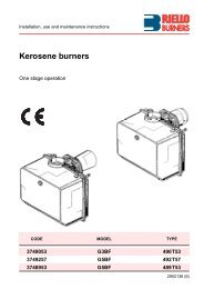
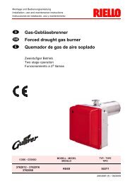
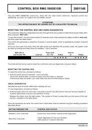
<strong>MODULATING</strong> <strong>LIGHT</strong> <strong>OIL</strong> <strong>BURNERS</strong>PRESS P/G SERIES P 140 P/G 415/830 ÷ 1660 kWP 200 P/G 590/1185 ÷ 2370 kWP 300 P/G 890/1780 ÷ 3560 kWP 450 P/G 1190/2670 ÷ 5340 kWThe PRESS P/G series of burners covers a firing range from 415 to 5340 kW.Setting can be “two stage progressive” or, alternatively, “modulating” with the installationof a PID logic regulator and respective probes, which guarantees a turn down ratio of 3:1.The versatility of this range makes the burner well suited for use on commercial or industrialapplications where the load factor is subject to wide variations over a short period of time.Simplified maintenance is achieved by Riello designed slide bar system, which allows easyaccess to all of the essential components of the combustion head.TS0039UK02
TECHNICAL DATAModelP 140 P/GP 200 P/GP 300 P/GP 450 P/GBurner operation modeModulating (with regulator and probes accessories) or Two-stage progressiveModulation ratio at max. output3 ÷ 1Servomotor.run timetypesSQM 1042kW415/830÷1660590/1185÷2370890/1780÷35601190/2670÷5340Heat outputMcal/h357/714÷1428507/1019÷2038765/1531÷30621023/2296÷4592kg/h35/70÷14050/100÷20075/150÷300100/225÷450Working temperature°C min./max.0/40Net calorific valuekWh/kgkcal/kg11,8610200Fuel / air dataViscosityPumpdeliveryAtomised pressureFuel temperaturemm 2 /s (cSt)typekg/hbarmax. °CTA2330 (25 bar)4 ÷ 6 (at 20°C)TA3TA4520 (25 bar)700 (25 bar)2550TA5880 (25 bar)Fuel pre-heaterNOFantypeCentrifugal with forward curve bladesAir temperaturemax. °C60Electrical supplyPh/Hz/V3N/50/400-230 (±10%) or 3/50/230 (±10%)Auxiliary electrical supplyPh/Hz/V1/50/230 (±10%)Control boxtypeLAL 1.25Total electrical powerkW4,55,51018Auxiliary electrical powerkW1,51,52,53Heaters electrical powerkW--Protection levelIP40Electrical dataPump motor electrical powerRated pump motor currentPump motor start up currentPump motor protection levelFan motor electrical powerkWAAIPkW34--------7,515Rated fan motor currentA8/13,59,5/16,417,5/3029/50,2Fan motor start up currentA51/8648/83113/195167/291Fan motor protection levelIP55typeIgnition transformerV1 - V2230 V - 2x6 kVI1 - I22,3 A - 35 mAOperationIntermittent (at least one stop every 24h)Sound pressuredB (A)86,585,589,590EmissionsSound powerCO emissionGrade of smoke indicatorCxHy emissionWmg/kWhN° Bacharachmg/kWh--< 35< 0,6< 8 (after the first 20 seconds)NOx emissionmg/kWh< 200< 200< 200< 220ApprovalDirectiveConforming toCertification89/336 - 73/23 - 92/42 - 98/37 EECEN 267DIN 5G459/2000 DIN 5G460/2000 DIN 5G461/200089/336-73/23-98/37 EECDIN 5G462/2000Reference conditions:Temperature: 20°CPressure: 1013,5 mbarAltitude: 100 m a.s.l.Noise measured at a distance of 1 meter.Since the Company is constantly engaged in the production improvement, the aesthetic and dimensional features,the technical data, the equipment and the accessories can be changed.This document contains confidential and proprietary information of RIELLO S.p.A. Unless authorised, this informationshall not be divulged, nor duplicated in whole or in part.2
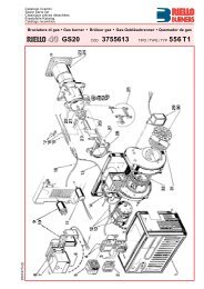
FIRING RATES1801816016P 300 P/GP 450 P/G14014P 200 P/GP 140 P/G1201210010808606404mm H 2O200hPa (mbar)20050 100 150 200 250 300 350 400 450kg/h05001000 1500 2000 2500 3000 3500 4000 45005000kWUseful working field for choosing the burnerModulation rangeTest conditions conforming to EN 267:Temperature: 20°CPressure: 1013.5 mbarAltitude: 100 m a.s.l.3
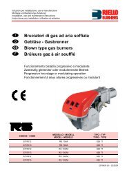
FUEL SUPPLYHYDRAULIC CIRCUITVarious hydraulic circuits are available, depending on fueloutput asset according to local norms of steam generators.The burners are fitted with two valves (a safety valve andan operation valve) and an oil filter along the oil line fromthe pump to the nozzle.A pressure regulator on the return circuit from the nozzleallows to vary the quantity of fuel burnt.A double safety valve on the return circuit avoids oil leakagefrom the nozzle when the burner is in stand-by and prepurgephase.The models are fitted with a maximum pressure switch onthe oil return circuit.Example of the hydraulic circuit on PRESS 200 P/GEN 267 > 100 kg/hPFOVS VFVR1 VRPOmaxM SMROMRUPFOVSVFUMRSMROPO maxVRVR1Pump with filter and pressureregulator on the output circuitOil filterSafety valve on the output circuitWorking valve on the output circuitNozzlePressure gauge on the return circuitServomotorPressure regulator on the returncircuitMax. Oil pressure switch on thereturn circuit1st safety valve on the return circuit2nd safety valve on the return circuit4
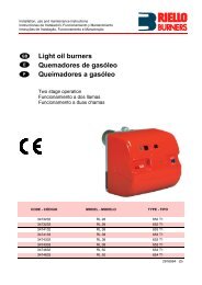
SELECTING THE FUEL SUPPLY LINESThe fuel feed must be completed with the safety devices required by the local norms.The table shows the choice of piping diameter for the various burners, depending on the differencein height between the burner and the tank and their distance.ModelDiameter piping+H, -H (m)+2,0+1,5+1,0+0,50-0,5-1,0-1,5-2,0-3,0MAXIMUM EQUIVALENT LENGTH FOR THE PIPING L[m]P 140 P/GP 200 P/GP 300 P/GØ14mmL max (m)5045403530252015105Ø16mmL max (m)70656050454035302515Ø16mmL max (m)4035302520181513105Ø18mmL max (m)60555045403530252010Ø1/2”L max (m)25232018151210853Ø 3/4”L max (m)85807065605045353015P 450 P/GØ 3/4” Ø1”L max (m) L max (m)55 13050 12045 11040 10035903080257020601545102567109 5 VP+H10 cm847 5 3921H Difference in height pump-foot valveØ Internal pipe diameterP Max. height 10 mV Height 4 m1 Burner2 Burner pump3 Filter4 Manual shut off valve5 Suction pipework6 Bottom valve7 Remote controlled rapid manualshut off valve(compulsory in Italy)8 Type approved shut off solenoid valve(compulsory in Italy)9 Return pipework10 Check valve-H6noteWith ring distribution oil systems, the feasible drawings and dimensioning are the responsibilityof specialised engineering studios, who must check compatibility with the requirements andfeatures of each single installation.5
VENTILATIONThe ventilation circuit is provided with a forward blades centrifugalfan, which guarantees high pressurelevels at the required air deliveries andpermits installation flexibility.In spite of the remarkable output powerand of the very high pressure performances, the structuresof PRESS models are extremely compact.The use of sound proofing boxes help in reducing thenoise level.A variable profile cam connects fuel and air setting,ensuring fuel efficiency in all firing rates.Example of servomotor forair/light oil settingCOMBUSTION HEADTwo different lengths of the combustion head can be chosen forthe various models of the PRESS P/Gseries of burners.The choice depends on the thickness ofthe front panel and the type of the boiler.Depending on the type of heat generator, it is necessaryto check the correct head penetration into the combustionchamber.These burners are equipped with a variable geometrycombustion head. The chance to control air speed incombustion head is essential to gain the full advantageof a modulating burner. This function allows optimumcombustion performance through the working field,ensuring peak combustion efficiency thus saving on fuelconsumption.The following diagram shows the flame dimensions inrelation to the burner output. The length and diametershown in the diagram below should be employedfor a preliminary check: it is required a more careful investigation if combustionchamber dimensions are much different from the above reported values.Flame dimensionsExample of a PRESS P/G burnercombustion head74Flame lenght (m)65432100 1 2 3L maxL minD maxD min3,532,521,510,504 5 6 7 8 9 10Burner output (MW)Flame diameter (m)DLExample:Burner thermal output = 3500 kW;L flame (m) = 3,5 m (medium value);D flame (m) = 1 m (medium value)6
ADJUSTMENTBURNER OPERATION MODEThe PRESS P/G series of burnerscan have “two-stage progressive”or “modulating” operation.On “two-stage progressive”operation, the burner graduallyadapts the output to therequested level, by varyingbetween two pre-set levels (seepicture A).Example of a regulator“Two-stage progressive” operationOutput Controlled variablePicture A°CbarMAXMINtimetimeOn “modulating” operation,normally required in steamgenerators, in superheatedboilers or diathermic oilburners, a specific regulatorand probes are required.These are supplied asaccessories that must beordered separately. Theburner can work for longperiods at intermediateoutput levels (see picture B).“Modulating” operationOutput Controlled variablePicture B°CbarMAXMINtimetimeSTART UP CYCLERemote controlMNormalLock-out due to ignition failureVSVFVRLock-out5s 45s 22,5s 2,5s 5s 5s 45s 22,5s 2,5s 5smaxMmin0time (s)0time (s)0” The burner begins the start-up cycle: the motor starts running.5”-50” The servomotor opens the air damper at the maximum position.50”-72,5” Pre-purge phase with air damper open.72,5”-92,5” The servomotor takes the air damper to the ignition position.92,5” Ignition transformer turns on.95” Oil solenoid valves open and flame detection with P.E. cell is activated.100” After a safety time of 7,5” the ignition transformer turns off if there isthe flame, otherwise lock-out happens.7
WIRING DIAGRAMSElectrical connections must be made byqualified and skilled personnel, accordingto the local norms.Example of the terminal board forelectrical connections forP 140-200-300-450 P/G models“TWO-STAGE PROGRESSIVE” OPERATIONDirect start-up versionP 140-200-300 P/GStar delta start-up versionP 300-450 P/GMB L1 L2 L3 N L N 1 2 3 4 5 QTL (1)T6APTS SPFI1TR (1)PY2 Y1 L N M B1 GTH/LMB 35 36 37 38 39 40 41 42 43 44 L N 1 2 3 4 5 QTSTLPPHSS2I1T6ATRPY2 Y1 L N M B1 GLPE L1 L2 L3 N3N~50Hz 400/230V3~ 50Hz 230VM3~L N~ 50Hz 230VMB - Burner terminal boardL - Lead section (see table A)TS - Safety thermostatS - External lock-out signalTL - Threshold thermostatTR - High/low flame settingthermostatT6A - 6A fuseF - Fuse (see table A)I1 - Manual switch1 2 3 4 35 36 37 38 39 40 41 42 43 44 45 5 6MAPE L1 L2 L3 NFL3N~50Hz 400/230V3~ 50Hz 230VM3~MB - Burner terminal boardL, H - Lead section (see table A)TS - Safety thermostatS, S2 - External lock-out signalTL - Threshold thermostatTR - High/low flame settingthermostatT6A - 6A fuseF - Fuse (see table A)MA - Star delta starterI1 - Manual switch“<strong>MODULATING</strong>” OPERATION - temperature probeDirect start-up versionP 140-200-300 P/GStar delta start-up versionP 300-450 P/GRWF 40RWF 40Q13 Q14 G- G+ Q Y1Y2 L1 N M1 I1G1+ TEQ13 Q14 G- G+ Q Y1Y2 L1 N M1 I1G1+TEMB L1 L2 L3 N L N 1 2 3 4 W1W2Q Y2 Y1 L N M B1 GT6Aa b c dTS SPFI1BTMB 35 36 37 38 39 40 41 42 43 44 LN 1 2 3 4 W1W2Q Y2 Y1 L N M B1 GTSPa b c dHSS2T6AI1BTLPE L1 L2 L3 N3N~50Hz 400/230V3~ 50Hz 230VM3~L N~ 50Hz 230VMB - Burner terminal boardL - Lead section (see table A)TS - Safety thermostatS - External lock-out signalRWF 40 - Regulator (fitted to theburner)BT - Temperature probeT6A - 6A fuseF - Fuse (see table A)I1 - Manual switch1 2 3 4 35 36 37 38 39 40 41 42 43 44 45 5 6MAPE L1 L2 L3 NFL3N~50Hz 400/230V3~ 50Hz 230VM3~MB - Burner terminal boardL, H - Lead section (see table A)TS - Safety thermostatS, S2 - External lock-out signalRWF 40 - Regulator (fitted to theburner)BT - Temperature probeT6A - 6A fuseF - Fuse (see table A)MA - Star delta starterI1 - Manual switch8
“<strong>MODULATING</strong>” OPERATION - pressure probeDirect start-up versionP 140-200-300 P/GStar delta start-up versionP 300-450 P/GRWF 40RWF 40Q13 Q14 G- G+ Q Y1Y2 L1 N M1 I1G1+ TEQ13 Q14 G- G+ Q Y1 Y2 L1 N M1 I1G1+TEMB L1 L2 L3 N L N 1 2 3 4W1W2QY2 Y1 L N M B1 GFT6ATSPSI1BP1 24/20mAMB 35 36 37 38 39 40 41 42 43 44 LN 1 2 3 4 W1W2Q Y2 Y1 L N M B1 GTSP1 2HSS2I1 BP 4/20mAT6ALPE L1 L2 L3 N3N~50Hz 400/230V3~ 50Hz 230VM3~L N~ 50Hz 230VMB - Burner terminal boardL - Lead section (see table A)TS - Safety thermostatS - External lock-out signalRWF 40 - Regulator (fitted tothe burner)BP - Pressure probeT6A - 6A fuseF - Fuse (see table A)I1 - Manual switch1 2 3 4 35 36 37 38 39 40 41 42 43 44 45 5 6MAPE L1 L2 L3 NFL3N~50Hz 400/230V3~ 50Hz 230VM3~MB - Burner terminal boardL, H - Lead section (see table A)TS - Safety thermostatS, S2 - External lock-out signalRWF 40 - Regulator (fitted to theburner)BP - Pressure probeT6A - 6A fuseF - Fuse (see table A)MA - Star delta starterI1 - Manual switchThe following table showsthe supply lead sectionsand the type of fuse to beused.ModelFLHAmm 2mm 2P 140 P/G230VT252,5-400VT252,5-DirectP 200 P/G230VT354-400VT252,5-P 300 P/G230VT636-400VT504-P 300 P/G230VT5064Star delta400VT3542,5P 450 P/G230VT63106400VT5064Table AEMISSIONSmg/kWh250200NOx EMISSIONS150100500P 140 P/G P 200 P/G P 300 P/G P 450 P/Gmg/kWh5040CO EMISSIONSdB(A)10080NOISE EMISSIONS30602040102000P 140 P/G P 200 P/G P 300 P/G P 450 P/G P 140 P/G P 200 P/G P 300 P/G P 450 P/GThe emission data has been measured in the various models at maximum output, according toEN 267 standard.9
OVERALL DIMENSIONS (mm)BURNERAEF - F(1)O -O (1)HIBModel A B E F - F (1) H IP 140 P/GP 200 P/GP 300 P/GP 450 P/G765796858950(1) Length with extended combustion head36539644750889089010001070363391444476----473501574606222250295336467467496525O - O (1)1250 - 13601280 - 13901440 - 15701546 - 1676BURNER - B<strong>OIL</strong>ER MOUNTING FLANGELOLMNMModelP 140 P/GP 200 P/GP 300 P/GP 450 P/GL260260260310M230---NM14M16M18M20O225255300340PACKAGINGZX - X (1)YModel X - X (1) Y Z kgP 140 P/GP 200 P/GP 300 P/GP 450 P/G1500150017801780(1) Length with extended combustion head9309301085108590590599099013022023830010
INSTALLATION DESCRIPTIONInstallation, start-up and maintenance must be carried out byqualified and skilled personnel.All operations must be performed in accordance with thetechnical handbook supplied with the burner.BURNER SETTINGAll the burners have slide bars, for easier installation and maintenance.After removing the cover, the split pin and the pin, the nuts and the screws, dismantle the blast tubeform the burner of approximatively 100-120mm and fix it to the boiler.Adjust the combustion head.Refit the burner casing to the slide bars.Install the nozzle, choosing it on the basis of the maximum boiler output and following the diagramsincluded in the burner instruction handbook.Check the position of the electrodes.Close the burner, fasten the screws, the nuts, the split pin and the pin.HYDRAULIC / ELECTRICAL CONNECTIONS AND START UPThe burners are supplied for connection to two pipes fuel supply system.Connect the ends of the flexible pipes to the suction and return pipework using the supplied nipples.Make the electrical connections to the burner following the wiring diagrams included in the instructionhandbook.Prime the pump by turning the motor (after checking rotation direction if it is a three phase motor).On start up, check:- Pressure pump and valve unit regulator (to max. and min.)- Combustion quality, in terms of unburned substances and excess air.11
BURNER ACCESSORIESNozzlesThe return nozzles must be ordered separately. The followingtable shows the features and codes on the basis of themaximum required output.BurnerRated outputkg/h (*)NozzlesNozzles Bergonzo B5 45°without "SA"needle codeP 140 P/GP 140 P/GP 140 P/GP 140 - 200 P/GP 140 - 200 P/GP 200 - 300 P/GP 200 - 300 P/GP 200 - 300 P/GP 300 - 400 P/GP 300 - 400 P/GP 300 - 400 P/GP 300 - 400 P/GP 450 P/GP 450 P/GP 450 P/GP 450 P/GP 450 P/GP 450 P/G708090100125150175200225250275300325350375400425450300930330093053009307300931030093123009314300931630093183009320300932230093243009326300932830093303009332300933430093363009338(*) Nozzle rated delivery is referred to atomised pressureNozzles Fluidics N2 45°withoutneedle code304547130454723045473304547530454773045479304548130454833045485304548730454893045491304549330454953045497304549930455003045501Spacer kitIf burner head penetration in the combustion chamber needs to be reduced, varying thickness spacersare available, as given in the following table.Spacer kitSBurnerP 140 P/GP 200 P/GP 300 P/GP 450 P/GSpacer thickness S (mm)110110130130Kit code3000722300072230007233000751Sound proofing boxIf noise emissions need to be reduced, sound proofing hoods are available, as given in the followingtable.BurnerP 140 P/G - P 200 P/GP 300 P/G - P 450 P/G(*) according to EN 15036-1 standardSound proofing boxBox type Average noisereduction [dB(A)] (*)C4/510C710Box code3010404301037612
Accessories for modulating operationTo obtain modulating operation, the PRESS P/G series of burners requires a regulator with threepoint outlet controls. The following table lists the accessories for modulating operation with theirapplication range.BurnerP 140 P/G - P 200 P/GP 300 P/G - P 450 P/GRegulator typeRWF 40Regulator code3010211The relative temperature or pressure probes fitted to the regulator must be chosen on the basis ofthe application.Probe typeTemperature PT 100Pressure 4 ÷ 20 mAPressure 4 ÷ 20 mARange (°C) (bar)-100 ÷ 500°C0 ÷ 2,5 bar0 ÷ 16 barProbe code301011030102133010214Depending on the servomotor fitted to the burner, a three-pole potentiometer (1000 Ω) can be installedto check the position of the servomotor. The KITS available for the various burners are listed below.BurnerP 140 P/G - P 200 P/G - P 300 P/G - P 450 P/GPotentiometerkit code3010021Burner supportFor easier maintenance, a mobile burner support has been designed, which means the burner canbe dismantled without the need of forklift trucks.Burner supportBurnerP 300 P/G - P 450 P/GSupport code300073113
SPECIFICATIONA specific index guides your choice of burner fromthe various models available in the PRESS P/G series.Below there is a clear and detailed specificationdescription of the product.DESIGNATION OF SERIESSeries :PRESSSize 140 ... 450Operation : T/G Three stageP/G ModulatingEmission : ... Class 1 EN267Head : TC Standard headTL Extended headFlame control system :FS1 Standard (1 stop every 24 h)FS2 Continuous working (1 stop every 72 h)Electrical supply to the system :3/230/50 3/230V/50Hz3/400/50 3N/400V/50Hz3/230-400/50 3/230V/50Hz - 3N/400V/50Hz3/220-380/60 3/220/60Hz - 3N/380V/60Hz3/200/50-60 3/200V/50-60HzAuxiliary voltage :230/50 230V/50Hz220/60 220V/60Hz110/50-60 110V/50-60HzPRESS 140 P/G TC FS1 3/230-400/50 230/50-60BASIC DESIGNATIONEXTENDED DESIGNATIONAVAILABLE BURNER MODELSP 140 P/G TC 3/230-400/50 230/50P 140 P/G TL 3/230-400/50 230/50P 200 P/G TC 3/230-400/50 230/50P 200 P/G TL 3/230-400/50 230/50P 300 P/G TC 3/230-400/50 230/50P 300 P/G TL 3/230-400/50 230/50P 300 P/G TC 3/230/50 230/50P 300 P/G TL 3/230/50 230/50P 300 P/G TC 3/400/50 230/50P 300 P/G TL 3/400/50 230/50P 450 P/G TC 3/230/50 230/50P 450 P/G TL 3/230/50 230/50P 450 P/G TC 3/400/50 230/50P 450 P/G TL 3/400/50 230/50Other models are available on request.14
PRODUCT SPECIFICATIONBurner:Monoblock forced draught oil burner with two-stage progressive or modulating operation, with aspecific kit, fully automatic, made up of:- Air suction circuit- Fan with forward curved blades high performance pressure levels- Air damper for air setting and automatic oil output regulator controlled by a servomotor withvariable cam- Starting motor at 2850rpm, three-phase 400V with neutral, 50Hz- Combustion head, that can be set on the basis of the combustion output, fitted with:- Stainless steel end cone, resistant to corrosion and high temperatures- Ignition electrodes- Flame stability disk- Gears pump for high pressure fuel supply, fitted with:- Filter- Pressure regulator- Connections for installing a pressure gauge and vacuometer- Internal by-pass for single pipe installation- Valve unit with a double oil safety valve on the output circuit and double safety valve on the returncircuit- Safey oil pressure switch for stop the burner in the case of problems on return circuit- Photocell for flame detection- Flame control panel, fitted with control function for the correct positioning of the servomotor andpossibility of post-ventilaton- Flame inspection window- Slide bars for easier installation and maintenance- Protection filter against radio interference- IP 40 electric protection level.Conforming to:- 89/336/EC directive (electromagnetic compatibility)- 73/23/EEC directive (low voltage)- 92/42/EEC directive (performance)- 98/37/EEC directive (machinery)- EN 267 (liquid fuel burners).Standard equipment:- 2 flexible pipes for connection to the oil supply network- 2 nipples for the connection to the pump- wiring looms fittings for electrical connections- 4 screws for fixing the burner flange to the boiler- 1 thermal screen- instruction handbook for installation, use and maintenance- spare parts catalogue- 2 slide bar extensions (for the extended head models of P 300 P/G e P 450 P/G).Available accessories to be ordered separately:- return nozzles- head lenght reduction kit (spacer)- sound-proofing box- RWF 40 output regulator- pressure probe 0 ÷ 2,5 bar- pressure probe 0 ÷ 16 bar- temperature probe -100 ÷ 500 °C- potentiometer kit for the servomotor- burner support.15
ISO 9001 Cert. n. 0061RIELLO S.p.A. - Via Ing. Pilade Riello, 5 - 37045 Legnago (VR) ItalyTel. ++39.0442630111 - Fax ++39.044221980Internet: http://www.<strong>riello</strong>burners.com - E-mail: info@<strong>riello</strong>burners.comSince the Company is constantly engaged in the production improvement, the aesthetic anddimensional features, the technical data, the equipment and the accessories can be changed.This document contains confidential and proprietary information of RIELLO S.p.A.Unless authorised, this information shall not be divulged, nor duplicated in whole or in part.