AIR CONDITIONER - Heronhill Air Conditioning Ltd
AIR CONDITIONER - Heronhill Air Conditioning Ltd AIR CONDITIONER - Heronhill Air Conditioning Ltd
FILE NO. SVM-05020Cooling ModelTable 9-6-2No.ProcedureCheck Point (Symptom)Causes1Shut off the power supply andremove the P.C. board assemblyfrom the electronic parts base.Remove the connecting cable fromthe terminal block.1. Is the fuse blown?1.•Application of shock voltage.•Overload by short-circuit of theparts.2Remove the connector for the motor,and turn the power on.If the OPERATION lamp blinks(0.5 sec. : ON, 0.5 sec. : OFF) whenthe power turning on, the checkingpoints described as 1-4 of rightcolumn are not necessary toperform.Voltage check1.Between 3 of RY01 and CN31(AC 220~240V)2.Between + and − of C50(DC 12 ~ 16V)3.Between 12V and GND4.Between 5V and GND1.•AC power cord is defective.•Poor contact of the terminal plate.•Miss wiring of the power relay.2.•Capacitor (C01, C15) is defective.•Line filter (L01) is defective.•Diode (DB01) is defective.3. IC51 are detective.4.IC61 are defective.3Make the operation status bypushing once the [ ]button, except the status of [FANONLY], [ON TIMER].Voltage check1. Voltage of relay coil. (DC 12V)Between pin 10 of IC31 and GNDBetween pin 11 of IC31 and GND2.Between No. 1 and 2 ofconnecting cable terminal block.(AC 220~240V)1. Breaking wire of the relay coil,defective relay driver. (IC31)2. Poor contact of relay.4Start the operation with the systemwhich the time of the restart delaytimer is shortened.1. All indicators light for 3 sec..2. Indicators do not indicate normallyafter approximate 3 sec..}Defective indicator, or poorhousing assembly. (CN14)5Make the operation status bypressing once the [ ]button.1.The time of the restart delay timeris shortened.2.Cool operation3.Air volume [AUTO]4. Make the setting temperature lowerenough than room temperature.5. Continuous operation.1. Compressor does not operate.2. OPERATION lamp blinks.1.The temperature of the indoorheat exchanger is abnormallylower.2.Poor contact of the heatexchanger sensor. (The connectoris disconnected.) (CN01)3.Heat exchanger sensor, mainP.C. board are defective. (Refer toTable 9-6-2 for the judgment ofdefective resistance values.)4.Main P.C. board is defective.6Turn the power on after connectingthe motor connector. Start theoperation with the followingcondition.1.Operation [Cooling]2.Airflow [High fan]3.Continuous operation1.Motor does not rotate. (The keyoperation is accepted.)2. The Motor rotates, but it vibratestoo much.1. Poor contact of the motorconnector.2. P.C. board is defective.− 69 −
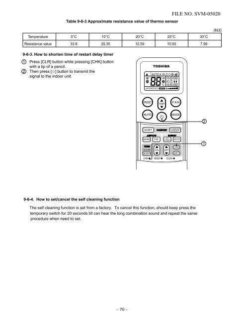
Table 9-6-3 Approximate resistance value of thermo sensorFILE NO. SVM-05020Temperature 0°C 10°C 20°C 25°C 30°C(kΩ)Resistance value 33.8 20.35 12.59 10.00 7.999-6-3. How to shorten time of restart delay timer1 Press [CLR] button while pressing [CHK] buttonwith a tip of a pencil.2 Then press [ ] button to transmit thesignal to the indoor unit.219-6-4. How to set/cancel the self cleaning functionThe self cleaning function is set from a factory. To cancel this function, should keep press thetemporary switch for 20 seconds till can hear the long combination sound and repeat the sameprocedure when need to set.− 70 −
- Page 19 and 20: FILE NO. SVM-050204-7. Outdoor Unit
- Page 21 and 22: 5-2. RAS-10UKHP-ES4 / RAS-10UAH-ES4
- Page 23 and 24: FILE NO. SVM-050205-4. RAS-10UKP-ES
- Page 25 and 26: 6. CONTROL BLOCK DIAGRAMFILE NO. SV
- Page 27 and 28: 7. OPERATION DESCRIPTIONFILE NO. SV
- Page 29 and 30: 7-2-3. Dry operation([MODE] button
- Page 31 and 32: 7-3. Hi POWER Mode([Hi POWER] butto
- Page 33 and 34: 7-7. Current Limit Control *Heat pu
- Page 35 and 36: 7-8-2. How to cancel auto restart f
- Page 37 and 38: FILE NO. SVM-050207-11. QUIET ModeQ
- Page 39 and 40: DANGER− 38 −FILE NO. SVM-05020
- Page 41 and 42: 8-3. Installation8-3-1. Optional in
- Page 43 and 44: 8-3-3. Installation/Servicing tools
- Page 45 and 46: FILE NO. SVM-050201. Securely fit t
- Page 47 and 48: FILE NO. SVM-050208-4-4. Piping and
- Page 49 and 50: FILE NO. SVM-050208-4-6. Drainage1.
- Page 51 and 52: 8-5-3. EvacuatingAfter the piping h
- Page 53 and 54: FILE NO. SVM-050202. Set the remote
- Page 55 and 56: 9-3. Primary Judgement9-3-1. Role o
- Page 57 and 58: Table 9-4-1FILE NO. SVM-05020Checkc
- Page 59 and 60: FILE NO. SVM-05020Cooling ModelOper
- Page 61 and 62: FILE NO. SVM-05020RAS-13UKP-ES4, RA
- Page 63 and 64: 9-5-5. Only outdoor fan does not op
- Page 65 and 66: FILE NO. SVM-050209-5-7. Only the i
- Page 67 and 68: 9-6. Troubleshooting for Remote Con
- Page 69: (3) Checking procedureHeat Pump Mod
- Page 73 and 74: FILE NO. SVM-05020No. Part name Pro
- Page 75 and 76: FILE NO. SVM-05020No. Part name Pro
- Page 77 and 78: FILE NO. SVM-0502011. EXPLODED VIEW
- Page 79 and 80: FILE NO. SVM-0502011-4. Outdoor Uni
- Page 81 and 82: 11-6. Outdoor Unit (RAS-13UA-ES4)FI
- Page 83 and 84: FILE NO. SVM-0502011-8. Outdoor Uni
Table 9-6-3 Approximate resistance value of thermo sensorFILE NO. SVM-05020Temperature 0°C 10°C 20°C 25°C 30°C(kΩ)Resistance value 33.8 20.35 12.59 10.00 7.999-6-3. How to shorten time of restart delay timer1 Press [CLR] button while pressing [CHK] buttonwith a tip of a pencil.2 Then press [ ] button to transmit thesignal to the indoor unit.219-6-4. How to set/cancel the self cleaning functionThe self cleaning function is set from a factory. To cancel this function, should keep press thetemporary switch for 20 seconds till can hear the long combination sound and repeat the sameprocedure when need to set.− 70 −


