AIR CONDITIONER - Heronhill Air Conditioning Ltd
AIR CONDITIONER - Heronhill Air Conditioning Ltd
AIR CONDITIONER - Heronhill Air Conditioning Ltd

You also want an ePaper? Increase the reach of your titles
YUMPU automatically turns print PDFs into web optimized ePapers that Google loves.
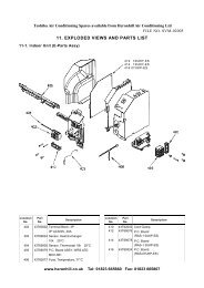
FILE NO. SVM-050208-5-4. Wiring connection1. Remove the valve cover from the outdoor unit.2. Connect the connecting cable to the terminal asidentified with their respective matched numbers onthe terminal block of indoor and outdoor unit.3. When connecting the connecting cable to theoutdoor unit terminal, make a loop as shown in theinstallation diagram of indoor and outdoor unit, toprevent water coming in the outdoor unit.4. Insulate the unused cords (conductors) from anywater coming in the outdoor unit. Proceed them sothat they do not touch any electrical or metal parts.For RAS-13/10UAH10 mm10 mm70 mmEarth line60 mmTerminal blockTerminalscrewConnectingcableFig. 8-5-9ScrewEarthlineCord clamp8-6. How to Set Remote Control SelectorSwitchWhen two indoor units ae installed in seperated rooms,there is no need to change the selector switch.• When two indoor units are installed in the sameroom or the adjacent two rooms, they may becontrolled simultaneously with a single remotecontrol. To prevent this, set either unit and itsremote control to B setting. (Both units are set to Asetting before shipment.)• The remote control signal is not recived when theindoor unit setting is different from the remotecontrol one.1. Set the remote control selector switch with theindoor unit.1) Turn the circuit breaker of the main power switch offbefore setting the selector switch.2) Remove the <strong>Air</strong> inlet grille and Front panel. (Refer topage 63, 10-1)3) Select the terminal of selector switch from[A position] to [B position].For RAS-13/10/07UATerminal block10 mm60 mmEarth lineTerminalscrewScrewEarthline10 mm50 mmConnectingcableCord clampSelector SwitchFig. 8-5-10CAUTION• Wrong wiring connection may cause someelectrical parts burn out.• Be sure to comply with local codes on runningthe wire from indoor unit to outdoor unit (size ofwire and wiring method etc.)• Every wire must be connected firmly.LED AssemblyFig. 8-6-1NOTE• Wire type: H07 RN-F or 245 IEC66 (2.0 mm 2 ormore)− 51 −