AIR CONDITIONER - Heronhill Air Conditioning Ltd
AIR CONDITIONER - Heronhill Air Conditioning Ltd AIR CONDITIONER - Heronhill Air Conditioning Ltd
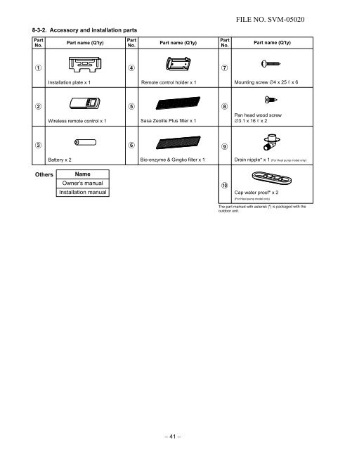
FILE NO. SVM-050208-3-2. Accessory and installation partsPartNo.Part name (Q'ty)PartNo.Part name (Q'ty)PartNo.Part name (Q'ty)147Installation plate x 1Remote control holder x 1Mounting screw ∅4 x 25 s x 62Wireless remote control x 15Sasa Zeolite Plus filter x 18Pan head wood screw∅3.1 x 16 s x 2369Battery x 2Bio-enzyme & Gingko filter x 1Drain nipple* x 1 (For Heat pump model only)OthersNameOwner’s manualInstallation manual!Cap water proof* x 2(For Heat pump model only)The part marked with asterisk (*) is packaged with theoutdoor unit.− 41 −
8-3-3. Installation/Servicing toolsFILE NO. SVM-05020In the case of an air conditioner using R410A, in order to prevent any other refrigerant from being chargedaccidentally, the service port diameter of the outdoor unit control valve (3 way valve) has been changed. (1/2UNF 20 threads per inch)• In order to increase the pressure withstand strength of the refrigerant piping, flare processing diameter andsize of opposite side of flare nuts have been changed. (for copper pipes with nominal dimensions 1/2 and 5/8)New tools for R410A Applicable to R22 model ChangesGauge manifoldCharge hoseElectronic balancefor refrigerant chargingTorque wrench(nominal dia. 1/2, 5/8)Flare tool(clutch type)Gauge for projectionadjustmentVacuum pump adapterGas leakage detectorAs pressure is high, it is impossible to measure bymeans of conventional gauge. In order to preventany other refrigerant from being charged, eachport diameter has been changed.In order to increase pressure withstand strength,hose materials and port size have been changed(to 1/2 UNF 20 threads per inch).When purchasing a charge hose, be sure toconfirm the port size.As pressure is high and gasification speed is fast,it is difficult to read the indicated value by meansof a charging cylinder, as air bubbles occur.The size of opposing flare nuts has been increased.Incidentally, a common wrench is used for nominaldiameters 1/4 and 3/8.By increasing the clamp bar's receiving hole,strength of spring in the tool has been improved.Used when flare is made with a conventional flaretool.Connected to conventional vacuum pump. It isnecessary to use an adapter to prevent vacuumpump oil from flowing back to the charge hose.The charge hose connecting part has two ports:one for conventional refrigerant (7/16 UNF 20threads per inch) and one for R410A. If thevacuum pump mineral oil mixes with R410A,a sludge may occur and damage the equipment.Exclusive for HFC refrigerant.• Incidentally, the "refrigerant cylinder" comes with the refrigerant designation (R410A) and protector coating inthe U. S ARI specified rose color (ARI color code: PMS 507).• Also, the "charge port and packing for refrigerant cylinder" require 1/2 UNF 20 threads per inchcorresponding to the port size of the charge hose.– 42 –
- Page 1 and 2: FILE NO. SVM-05020SERVICE MANUALAIR
- Page 3 and 4: 8. INSTALLATION PROCEDURE8-1 Safety
- Page 5 and 6: FILE NO. SVM-05020MODEL RAS-10UKHP-
- Page 7 and 8: FILE NO. SVM-05020Note : 1• Capac
- Page 9 and 10: 2. CONSTRUCTION VIEWSFILE NO. SVM-0
- Page 11 and 12: FILE NO. SVM-050203-2. RAS-10UKHP-E
- Page 13 and 14: 3-4. RAS-10UKP-ES4 / RAS-10UA-ES4FI
- Page 15 and 16: 3. WIRING DIAGRAMFILE NO. SVM-05020
- Page 17 and 18: FILE NO. SVM-050204-3. Outdoor Unit
- Page 19 and 20: FILE NO. SVM-050204-7. Outdoor Unit
- Page 21 and 22: 5-2. RAS-10UKHP-ES4 / RAS-10UAH-ES4
- Page 23 and 24: FILE NO. SVM-050205-4. RAS-10UKP-ES
- Page 25 and 26: 6. CONTROL BLOCK DIAGRAMFILE NO. SV
- Page 27 and 28: 7. OPERATION DESCRIPTIONFILE NO. SV
- Page 29 and 30: 7-2-3. Dry operation([MODE] button
- Page 31 and 32: 7-3. Hi POWER Mode([Hi POWER] butto
- Page 33 and 34: 7-7. Current Limit Control *Heat pu
- Page 35 and 36: 7-8-2. How to cancel auto restart f
- Page 37 and 38: FILE NO. SVM-050207-11. QUIET ModeQ
- Page 39 and 40: DANGER− 38 −FILE NO. SVM-05020
- Page 41: 8-3. Installation8-3-1. Optional in
- Page 45 and 46: FILE NO. SVM-050201. Securely fit t
- Page 47 and 48: FILE NO. SVM-050208-4-4. Piping and
- Page 49 and 50: FILE NO. SVM-050208-4-6. Drainage1.
- Page 51 and 52: 8-5-3. EvacuatingAfter the piping h
- Page 53 and 54: FILE NO. SVM-050202. Set the remote
- Page 55 and 56: 9-3. Primary Judgement9-3-1. Role o
- Page 57 and 58: Table 9-4-1FILE NO. SVM-05020Checkc
- Page 59 and 60: FILE NO. SVM-05020Cooling ModelOper
- Page 61 and 62: FILE NO. SVM-05020RAS-13UKP-ES4, RA
- Page 63 and 64: 9-5-5. Only outdoor fan does not op
- Page 65 and 66: FILE NO. SVM-050209-5-7. Only the i
- Page 67 and 68: 9-6. Troubleshooting for Remote Con
- Page 69 and 70: (3) Checking procedureHeat Pump Mod
- Page 71 and 72: Table 9-6-3 Approximate resistance
- Page 73 and 74: FILE NO. SVM-05020No. Part name Pro
- Page 75 and 76: FILE NO. SVM-05020No. Part name Pro
- Page 77 and 78: FILE NO. SVM-0502011. EXPLODED VIEW
- Page 79 and 80: FILE NO. SVM-0502011-4. Outdoor Uni
- Page 81 and 82: 11-6. Outdoor Unit (RAS-13UA-ES4)FI
- Page 83 and 84: FILE NO. SVM-0502011-8. Outdoor Uni
FILE NO. SVM-050208-3-2. Accessory and installation partsPartNo.Part name (Q'ty)PartNo.Part name (Q'ty)PartNo.Part name (Q'ty)147Installation plate x 1Remote control holder x 1Mounting screw ∅4 x 25 s x 62Wireless remote control x 15Sasa Zeolite Plus filter x 18Pan head wood screw∅3.1 x 16 s x 2369Battery x 2Bio-enzyme & Gingko filter x 1Drain nipple* x 1 (For Heat pump model only)OthersNameOwner’s manualInstallation manual!Cap water proof* x 2(For Heat pump model only)The part marked with asterisk (*) is packaged with theoutdoor unit.− 41 −


