Nadeem Qaiser, Naeem Iqbal,. Naeem Qaiser
Nadeem Qaiser, Naeem Iqbal,. Naeem Qaiser
Nadeem Qaiser, Naeem Iqbal,. Naeem Qaiser
- No tags were found...

You also want an ePaper? Increase the reach of your titles
YUMPU automatically turns print PDFs into web optimized ePapers that Google loves.
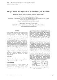
IEEE --- 2005 International Conference on Emerging TechnologiesSeptember 17-18, Islamabad<strong>Nadeem</strong> <strong>Qaiser</strong>D.E.E PIEAS,Nilore, Islamabad Pakistan.nadeem.qaiser@ pieas.edu.pk<strong>Naeem</strong> <strong>Iqbal</strong>D.E.E PIEAS,Nilore, Islamabad Pakistan.naeem.iqbal@pieas.edu.pk<strong>Naeem</strong> <strong>Qaiser</strong>D.C.I.S PIEAS,Nilore, Islamabad Pakistan.naeem.qaiser@ pieas.edu.pkAbstractThis paper considers the stabilization problem ofTranslational Oscillator with Rotational Actuator(TORA), a widely studied nonlinear mechanical system.TORA models resonance capture phenomenon observedin dual-spin spacecraft and rotating machinery. Thedesign of control Law for TORA is challenging becauseof its underactuated nature, posing problems in exactfeedback linearization. A novel nonlinear controllerdesign for TORA is presented; exploiting recentlyintroduced Dynamic Surface Control. The designprocedure is simpler and more intuitive than alreadypresented designs. Stability of the controller andadvantages over existing Backstepping controllers areanalyzed theoretically and verified using numericalsimulations.Keywords: TORA, Under Actuated MechanicalSystems, Dynamic Surface Control, Backstepping.1. IntroductionThis paper presents a novel Controller design forStabilization of a Benchmark Nonlinear System(TORA), based upon Dynamic Surface Control (DSC)technique. To the best of our knowledge it is the firstapplication of DSC for stabilization of UnderactuatedMechanical Systems (UMS), like TORA.UMS are mechanical control systems with feweractuators (i.e. controls) than configuration variables.TORA first introduced by Wan et al. [1], is aBenchmark nonlinear UMS. It has been extensivelyused as a test bed for nonlinear controllers for cascadesystems, mainly for passivity based approaches [2].Global stabilization of TORA system using IntegratorBackstepping procedure (IBS) has been known due toWan et al. [1]. IBS, based on results obtained bySontag and Sussman [3], is a powerful step-by-stepdesign tool. However it suffers not only the problem of“explosion of terms” but puts stringent condition oncertain system functions (being C n at least)[5,14] aswell. The control law obtained through a cumbersomedesign procedure is usually very complicated, forexample as by Wan et al. [1]. Multiple Sliding Surfaces(MSS) control [4], a procedure similar to IBS, wasdeveloped to avoid this issue. While successful in anumber of applications, MSS fell short of integratorbackstepping in terms of theoretical rigor, as the needfor analytical differentiation was pushed to a numericalone.Concept of Dynamic Surface Control (DSC), adynamic extension to MSS, introduced by Swaroop etal. [5] resolves these issues by using low pass filters. Itaddresses not only the issue of “explosion of terms”associated with IBS, but also solves the problem offinding ith state reference (desired) trajectoryderivatives numerically, for the MSS scheme. It issimple, more intuitive and applies to a more generalclass of systems as compared to the MSS scheme inWon and Hedrick [5]. We have used DSC techniques tostabilize TORA and show the design method simplicity,resulting in a less complicated control law.The paper starts formally with Section 2,containing the TORA dynamic model along withnecessary coordinate transformations. Controller designand stability discussion appear in section 3. Section 4presents simulation results comparing controllerperformance to an existing design followed byconcluding remarks in Section 5.2. Dynamical ModelThe TORA system as illustrated in Fig. 1 consists ofa translational oscillating platform, which is controlledvia a rotational eccentric mass. Whereas Fdrepresentsdisturbance forces (ignored in current modeling).0-7803-9247-7/05/$20.00 ©2005 IEEE488
IEEE --- 2005 International Conference on Emerging TechnologiesSeptember 17-18, Islamabad( mrcos( q))α( q ) = ( m r + I) − > 0, ∀q∈[ −ππ, ]and22 2 22 2 2 2( m1 + m2)2( mr2sin( q2)q2 + kq1 =2 2+) 12 2( m1 + m2)β ( qq , ) mgrsin( q) mrcos( q)This partially linearizes the system but brings the newcontrol in equations for both sub systems. A furtherLagrangian based global change of coordinates used byReza [12] is applied to decouple the inputFigure 1. The TORA SystemIts modeling has been done using differenttechniques [1][12] .We use Euler Lagrange method [6].Using configuration variables as shown in Fig. 4 theLagrangian is written as1 2 122Lqq ( , ) = mq 1 1+ m2[( q1 + rcos( q2) q2) + ( rsin( q2) q2) ]2 21 2 2 1 2+ ( mr2+ I) q2− kq1 1−mgr 2cos( q2)2 2(1)andd ∂L ∂L − = Qqu ( )dt ∂q∂qgives equations of motionas( m + m ) q + m rcos( q ) q 2− m r sin( q ) q+ k q = 01 2 1 2 2 2 2 2 2 2 1 12mr2 2cos( q2) q1+ ( mr2 2+ I) q2+ mgr2sin( q2)= τ(2)2.1. Collocated Feedback LinearizationThe state space model of TORA is unsuitable fordirect application of DSC [5] for not being in strictfeedback form. Feedback Linearization [7] employs achange of control and coordinate transformation, whichleaves the system dynamics linear or at least partiallylinear, more amenable to control. TORA is not fullylinearizable [1]. We use another tool applicable to allUMS, namely Collocated Partial FeedbackLinearization (CFL) due to Spong [8], to tackle thisissue, with following change of controlwithτ = α( q ) u + β( q, q )(3)2q = q + ( m rsin( q ))/( m + m )r1 2 2 1 2p = ( m + m ) p + m rcos( q ) pr21 2 1 2 2Rendering TORA into strict feedback formwhereqrrp=− k q + ε sin( q )q2rp2= mp= p= u1 r2m= ( m + m )−11 2kmr1 2ε =( m + m )1 22(4)(5)(6)Remark 1: System after coordinate transformation is acascade interconnection of a linear (Outer) (6) and anonlinear (Core or Reduced) (5) subsystem in strictfeedback form.3. Controller designThe controller is designed in two steps. Firstassuming q 2as input and applying Control LyapunovFunction (CLF) method, a Stabilization Function isfound for the core subsystem. Secondly, DynamicSurface Control is used to find a u such that q2keepsemulating required stabilization function, ultimatelystabilizing the total system.3.1. Step 1: Core Subsystem Controller DesignAssuming q2= u 0as an input for (5) and taking1 2V ( k1qrm 20( qr, pr) = + pr) as a Lyapunov function2489
IEEE --- 2005 International Conference on Emerging TechnologiesSeptember 17-18, Islamabadcandidate a control is found such that V is rendered−1negative definite. Trying u =−atan ( c p )0 1 rV=−εmp sin( atan ( c p ))≤0−10 r1 rπ0 < a0 and ∀ p2the requirement is found to be satisfied. Let the largestinvariant set where all solutions converge is2Ω= {[ pr, qr] ∈ : V( pr,qr) = 0} . That is pr= 0 , (7).It is concluded easily from (5) thatpr= 0⇒ pr= 0⇒ qr = 0, thus Ω= {0}. Backed byLaSalle’s invariance principle, this implies, GlobalAsymptotic Stability (GAS) of the origin of (5).r> 00(7)conditions inside the desired ball, such that thestate of the system is regulated within the desiredball at all instants of time.• The tracking (regulation) error eventually residesin a ball of radius ε .Proof: Swaroop et al. [5].It’s trivial to verify that listed assumptions aresatisfied by (6) regarding the system and by (8)regarding the trajectory as• System (6) is in strict feedback form1• f is a C function in its arguments• qdq22+2d≤2ddtK0Remark 2: The given choice of control is neither uniquenor the best. However later on it’s observed that itkeeps the interconnection stability proof simpler.Presence of initial conditions in a bounded sphere is notdiscussed yet. In stability discussion and simulationresults it’s seen that it doesn’t pose any problem and Rcan be set arbitrarily large.3.2. Step 2: Outer Subsystem Controller DesignDesign procedure:To stabilize (5) q2is required to follow the Let the error in q2be S1thentrajectory given asS1 = q2 − q2d(9)−1q2 =− atan ( c1p r)(8) S 1= q2 − q2d = p2 −q 2d(10)Applying DSC techniques we design a control law uthat achieves the task. Semi-global stability of theresulting closed loop system under the DSC isguaranteed with the following theorem.Theorem 1: Boundedness of Tracking Error Using DSCfor Non-Lipschitz Systems.Consider any non-Lipschitz nonlinear system instrict feedback form. Given any non-Lipschitznonlinearity with a known C 1 functions as its upperbound, and given any ε >0, there exists a set of surfacegains, K , . . . , 1Knand filter time constants,τ ,..., 1τnsuch that the Dynamic Surface Controllerguarantees:• There exists a > 0, such that for any desiredR 0ball of operation radius R > R 0and for a set ofsufficiently bounded trajectories2 n−1 2dx d x21d1dwhere x + + ...≤ K1dn−10, with K 0 possiblydt dtvarying with R, there exists a set of initialFiltering q 2,q () 2 dt is obtained.τ q ( t) + q ( t) = q q (0) = q (0) (11)1 2d 2d 2 2d2Now p2is chosen to driveS 1to zero:p2 = − K1S1 + q 2 d(12)Define the second surface to beFiltering p2,S2 = p2 − p2d(13)S = p − p = u−p (14)d2 2 2d2p () 2 dt is obtained.τ p () t + p () t = p p (0) = p (0) (15)2 2d 2d 2 2d2The control law is chosen to be490
IEEE --- 2005 International Conference on Emerging TechnologiesSeptember 17-18, Islamabadp − pu = p− K S = −K S2 2d2d2 2 2 2τ2p2d−K1( q2 −q2d)= −K2( p2 − p2d) +τ−1−q2d−atan ( c1pr)+ττ1 2Substitution in (3) yields required τ . A comparison todesign of Wan et al. [1] reveals the ease of design andsimplicity of obtained control law.2 2S1+ S2 Taking V1= as a Lyapunov function2candidate and calculating its derivative along the errorsystem trajectories yieldsV= S ( − K S + S ) + S ( −K S )1 1 1 2 2 2 22 2= − KS1 1+ SS1 2−KS 2 2≤0 ∀ K1, K2> 221(16)Thus the error subsystem is GAS, and its linearityimplies exponential stability [9] (p 157).3.3. Stability analysisCore (5) is GAS and initial (stabilization function)errors are exponentially removed, afterwards arbitrarilybounded stabilization function tracking is guaranteed byTheorem 1. Heuristically this indicates total systemstability. Following lines narrate a stronger theoreticalproof for the stability of the interconnection.Assuming sufficiently smaller filter time constants,the coupled system may be written asq= mpr r−1p r=− k1qr + ε − a c1pr+ S1S1=− K1S1+ S 2S=−K S2 2 2sin( tan ( ) )(17)(18)C 0( l 0, l ⎧1): ()| l 0, l 1 1,lim ( t ⎫= ⎨δ ⋅ δ ≤ δ ≤ δ ) = 0∞⎬t→⎩0 ⎭We say a function δ :t → δ ( t)is class- C with boundsl0, l1> 0 ifδ () ⋅ ∈ C0( l0, l1).Theorem 2: Global stability of cascade systems [10]Consider the following cascade nonlinear systemz= f( z, η) η = g( η)0(19)nmwhere f ∈R and g ∈R are smooth functions suchthat f (0, 0) = 0 and g(0) = 0 . Assume thefollowing conditions hold:1. For z = f( z, 0), z = 0 is globallyasymptotically stable.2. For η = g( η), η = 0is globally asymptoticallyand locally exponentially stable.3. For any solution η () t with initial conditionmη(0)∈R the solution of the z subsystem of(19) exists for all t ≥ 0 and is bounded.Then, ( z,η ) = 0 is globally asymptoticallystable for (3.8).Condition 1 and Condition 2 are already established (7)(16). The only non-constructive aspect of Theorem 2 isboundedness of the solutions of the subsystem (5)requiring for instance, Input to State Stability (ISS).Conditions for ISS are extremely restrictive.Fortunately there exists a less restrictive conditioninfluenced by the work of Sepulchre et al. [11](theorem 4.7, p.129), generalized by Reza et al [12] andgiven as follows.Theorem 3: Consider the nonlinear systemz = f( z, η)(20)Stability of (17)-(18) implies stability of TORA. Formalstability proof starts with a definition and two importanttheorems. Proofs can be found in mentioned references.Defnition 1: (class- C0functions)Define the following class of functions δ :≥0→ mwith a class- C 0input disturbance a smooth positivedefnite and proper function V (z), positive constantsρ ≥ 0 , k > 0 and ¸ λ ∈ (0,1] such that the followingconditions are satisfied:i) ∇V( z) ⋅ f( z,0) ≤ 0ii) ∇V ( z) ⋅h( z, η) ≤ kV ( z)λ491
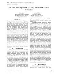
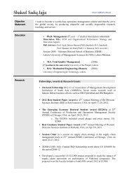
IEEE --- 2005 International Conference on Emerging TechnologiesSeptember 17-18, Islamabad∀ z ≥ ρ and η ≤l100where h( z, η) = ∫ Dηf ( z, sη)dsThen, any solution of the system (20) is bounded.Being solution of an exponentially stable systemSt ( ) ∈ class-C0with upper bound l0decidedarbitrarily by initial conditions of the rotor. Condition() i is already satisfied (7) thus only ( ii)remains to beproved for(17). Nowwhere⎡mpr⎤f( qr, pr, S)= ⎢ −1− kq1 r+ ε sin( − atan ( pr) + S1)⎥⎣⎦1∫hq ( , p, S) = D f( q, p, sSds )κr r S r r0⎡mS⎤2= ⎢−kS1 −κ1 −κ⎥2⎣−1εpS r 2εS2sin( S1− tan ( pr))1= and κ2 3/2 2=2(1 + pr) S1(1 + pr) S1∇V⋅ h= kmqS − ( kmpS + κ + κ )1 r 2 1 r 1 1 1⎦≤ kmql1 r 0−kmpl 1 r 0−∆ as S ≤l0As andκ are bounded functions, κ1 + κ2 =∆→0κ12with a growing pr, so some positive ρ , k can alwaysbe found such thatkml q − p −∆ ≤ kV( q, p)λ1 0 r r 0 r r∀ ( q , p ) ≥ ρ, λ=1 and k > k mlrr1 0Thus the solution of reduced system is bounded.Applying Theorem 3 this implies Semi GlobalAsymptotic Stability of TORA with designedcontroller, completing the proof.4. Simulation ResultsTo investigate initial condition effects and comparecontroller performance to existing IB designs,numerical simulations were done using ODE45 (Matlab6.5). For a fair performance comparison the initialconditions and parameters used for TORA have beenkept same as by Reza [12], i.e. q (0)=[1,0,0,0] T andm1 = 10, m2 = 1, k1= 10, r = 1, I = 10 . Followingcontroller parameters were used for simulationsDSC : a= π / 2, c = 1 K = 1, K = 2, τ =0.1 , τ =0.11 1 2 1 2IBS : c0=1, c1 = 1, c2 = 6, p0 = 10, p1= 10Initial Position of rotor determines first surfaceerror and hence the disturbance for the core system.This seems destabilizing the core system, as itdominates the bounded stabilizing function.S140200-200 10 20 30 40time [sec]Figure 2. Surface1 error for different initial conditionsBut for a variety of initial conditions Fig. 2, simulationsshow that error in stabilization function decaysexponentially, almost in five time constants.The controller effectively damps translationalvibrations of cart and brings rotor to origin inreasonable time, Fig. 3. The performance is much betterthan the one presented by Reza [12] and slightly betterthan the IBS design (Fig. 4). However DSC uses morecontrol effort in this case. Results are more thansatisfactory keeping in mind especially the designsimplicity with obtained performance.5. ConclusionsDSC technique has been applied to designcontroller for the TORA system. Model is brought tostrict feedback form before applying DSC. Stability ofthe system is analyzed theoretically by considering it asa cascade connection of an exponentially stable and aBIBO stable system. Some critical issues concerningthe initial conditions of the system are discussed.Design simplicity is shown and Controller performanceis compared to back-stepping technique through boththeoretically and simulation studies. It is concluded thatthe DSC technique with a simpler design procedurewhile leading to a less complicated controller, achievesfaster stabilization. Further improvements that we planare Robustification and generalization of scheme to thewhole subclass of UMS.492
IEEE --- 2005 International Conference on Emerging TechnologiesSeptember 17-18, Islamabadq1 [m], q2 [m/s]10.50-0.5-1q1p1q1 [m], q2 [m/s]10.50-0.5-1q1p1-1.50 10 20 30 40-1.50 10 20 30 40q2 [radians], p2 [radians/sec]50-5q2p2-100 10 20 30 40q2 [radians], p2 [radians/sec]50-5q2p2-100 10 20 30 4020u20uControl effort100-10Control effort100-10-20-200 10 20 30 40tim e [se c]Figure 3. IBS controller0 10 20 30 40time [se c]Figure 2. DSC controller6. AcknowledgementThe Authors like to acknowledge Higher EducationCommission of Pakistan for funding this research.References[1] C. J. Wan, D. D. Bernstein and T. V. Coppola , “GlobalSatbilization of the Oscillating Eccentric Rotor”, Proceed.33 rd Decision & Control Conference ,Florida Dec 1994.pp4024[2] M. Jankovic, D.Fontaine, and P. V. Kokotovic. “TORAexample: Cascade and passivity based control designs”. IEEETrans. On Control System Technology, 34(7):907-915, 1996.[3] E. D. Sontag and H. J. Sussman, “Further Comments onthe stability of the Angular Velocity of a Rigid Body”, Sys.Contr. Lett. Vol. 12, pp. 213-217[4] M. Won and J. K. Hedrick. “Multiple surface slidingcontrol of a class of uncertain nonlinear systems”,International Journal of Control, 64(4):693 – 706, 1996.[5] D. Swaroop, J. C. Gerdes, P. P. Yip, and J. K. Hedrick.“Dynamic surface control of nonlinear systems”, Proceedingsof the American Control Conference, 5:3028 – 3034, 1997.[6] Herbert Goldstein, “Classical Mechanics”, SecondEddition, Addison Wesley, USA, 1981.[7] Alberto Isidori. “Nonlinear control systems”, Springer,Berlin ; New York, 2nd edition, 1985.[8] M. W. Spong.” Energy based control of a class of underactuated mechanical systems “, 1996 IFAC World Congress,July 1996.[9] H. K. Khalil. “Nonlinear systems”, Prentice-Hall, USA3rd edition, 2000.[10] E. D. Sontag. “Remarks on stabilization and ISSstability”, Proceedings of th 28 th Conference on Decision andControl, pp 1376-1378, Tampa, FL Dec. 1989.[11] R.Sepulchre, M. Jancovic, , P. Kokotovic, “Nonlinearconstructive Control”. Springer -Verlag 1997.[12] R. Olfati-Saber. “Nonlinear Control of UnderactuatedMechanical Systems with Application to Robotics andAerospace Vehicles”: PhD Thesis 2001[13] Krstic, M., Kanellakapoulous, Kokotovic, P., 1995,“Nonlinear and Adaptive Control Design”, WileyInterscience, New York.[14] J.H. Green and J.K. Hedrick. Nonlinear speed control ofautomotive engines. In Proceedings of the American ControlConference, pages 2891–2897, San Diego, CA, 1990.493