RF Speech Clipper (Under Construction) - KG4JJH
RF Speech Clipper (Under Construction) - KG4JJH
RF Speech Clipper (Under Construction) - KG4JJH
- No tags were found...

You also want an ePaper? Increase the reach of your titles
YUMPU automatically turns print PDFs into web optimized ePapers that Google loves.
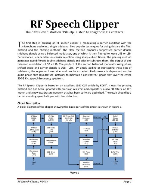
The balanced modulators and product detector are set up for single supply operation 8 . Theoutput voltage is a product of the input signal and the carrier. When U9 and U10 outputs arecombined, the resulting signal is upper sideband: (USB+LSB) + (USB‐LSB) = USB. This USB signalis buffered (Q2‐Q3), and then clipped by super diodes (Q4‐Q5). A super diode is formed whenthe base and collector of a transistor are connected so that the device exhibits a steep knee inthe forward transfer characteristics.The product detector (U11) performs demodulation of the clipped USB signal. The output is fedto a four‐pole 3 KHz low pass filter (U7), and buffer (U8A). The output of the buffer goes to theOUTPUT LEVEL control, through bypass switch S1, mic jumper block JP1, and then to the MICOUT jack.The audio signal from U4‐7 is fed to a meter amp (U8B) and then a peak detector 9 (Q6‐Q7). Themeter amp input capacitor C64 rolls off frequencies below 482 Hz to keep the LED meter fromindicating too much low frequency information. The output of the peak detector is sent to U12which drives ten LEDs to indicate the approximate level of <strong>RF</strong> processing in dB. The gain of U8Bis set so that the 3dB LED lights at the onset of clipping, as monitored at TP2. The use of activefilters before and after USB clipping permits as much as 30dB of clipping before distortionrenders the signal unusable.Figure 2 depicts the audio frequency response of the clipper (CLIPPING LEVEL set at midpoint),and was generated using TINA‐TI. The low frequency roll‐off slope below 300 Hz is 48dB/octave.The slope from 300Hz to 1.2 KHz is 10dB/octave, and is relatively flat from 1.2 KHz to 3 KHz.The high frequency roll‐off slope above 3 KHz is 60dB/octave.T60.0040.0020.00Gain (dB)0.00-20.00-40.00-60.00-80.00100 1k 10kFrequency (Hz)Figure 2<strong>RF</strong> <strong>Speech</strong> <strong>Clipper</strong>, <strong>KG4JJH</strong> Page 3
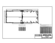
Problems will arise if the <strong>RF</strong> <strong>Speech</strong> <strong>Clipper</strong> circuit is powered from the same 12VDC powersupply that supplies the transceiver because the microphone ground is connected to the circuitground. To reduce noise and prevent ground loops, most modern transceivers keepmicrophone ground isolated from PTT ground until these signals are inside the radio. A 600Ω1:1 audio isolation transformer on the mic input would eliminate the problem, but mostreasonably priced transformers are limited in frequency response, add distortion, and havesome insertion loss. Most “wall wart” supplies introduce noise and hum so I built a high qualitylinear supply inside of a wall wart enclosure.I/O and ControlsJ1 and J2 are RJ‐45 mic input and output jacks, respectively. J4 provides an additional mic inputfor 3.5mm connectors. Jumper block JP1 allows the user to place jumpers to match the micwiring for most transceivers. Jumper block JP2 applies mic bias voltage as needed for electretmics. LED D3 indicates power, and S1 switches the <strong>RF</strong> <strong>Speech</strong> <strong>Clipper</strong> in and out. R1 is theCLIPPING LEVEL control and sets the input gain, while R84 controls the OUTPUT LEVEL. In use,the OUTPUT LEVEL should be adjusted to provide the same signal amplitude as when the <strong>RF</strong><strong>Speech</strong> <strong>Clipper</strong> is switched out. The LED meter monitors the audio signal from the output of U4and displays a 30 dB range, providing feedback on the approximate amount of <strong>RF</strong> clipping.<strong>Construction</strong>A prototype PC board (PCB) was ordered from ExpressPCB 10 . At the two board minimum, thecost per “standard service” board (no solder mask or silkscreen) is $66. Email me and I willcollect names and compile groups of 10 or more to get the PCB cost down. These PCBs will be“production service” boards which feature a solder mask and component silkscreen.All components are through‐hole and mount on the PCB. This eliminates external wiring andmakes testing and troubleshooting easier. The PCB ground plane isolates and shields the 500KHz carrier from the rest of the circuitry. All trimmer pots have been eliminated, allowing theuser to build this unit without any test equipment. The PCB is double sided with plated‐thruholes and slides into the bottom slots of the extruded aluminum enclosure. The color of theenclosure and control knobs can be selected by the builder with a choice of clear or blackanodized aluminum. Also available for the enclosure are red, yellow, translucent red andtranslucent blue bezels. As with most projects, the prototype PCB and enclosure total to abouthalf of the building cost.Mount all 215 components on the component side of the PCB, installing the smallercomponents first. I cleaned the solder flux from the board using a 50‐50 mix of acetone andisopropyl alcohol and a toothbrush.To complete the <strong>RF</strong> <strong>Speech</strong> <strong>Clipper</strong>, print the panel drilling templates (page 3 of 5) by settingthe Adobe Acrobat page scaling to “none”. Ensure that the box at the top of the printed pagemeasures exactly 7 inches. Measure and mark the panel center lines with a pencil. Cut thetemplates out and glue‐stick them to the panel, aligning the center lines. Center punch and drillall holes and use a small file for the rectangular holes. Apply a coat of Krylon flat black spray<strong>RF</strong> <strong>Speech</strong> <strong>Clipper</strong>, <strong>KG4JJH</strong> Page 4
paint to the panels to cover the hole edges. Bake the panels in an oven at 300°F for 15 minutes.Apply labels using dry transfer lettering or a label writer. Spray several light coats of flat lacquerover dry transfer lettering for protection. Use black text on the natural aluminum enclosure orwhite text on the black enclosure. Install the enclosure top plate and the front and rear bezelsand panels. Add the rear panel ground screw (and internal washers as needed), mounting feet,jack nut, control knobs, and stick‐on feet.The power supply is built on perf board using point to point wiring of component leads whenpossible. Voltage regulator (U13) does not require a heat sink because the circuit only drawsabout 100mA.Cables and SetupYaesu FT‐817/857/897 and Kenwood TS‐480 owners can plug the rig’s standard microphonedirectly into the <strong>RF</strong> <strong>Speech</strong> <strong>Clipper</strong>. Connection to the radio is made using a standard CAT‐5cable. Adapters for other microphones and radios can be fabricated with a short CAT‐5 cablecut in half and the appropriate connectors attached on each end. Round 8‐pin Foster male andfemale cable connectors are listed in the parts list. For the MIC INPUT, wire a Foster male cableconnector (pins 1‐8) to one half of the CAT‐5 cable (pins 1‐8). For the MIC OUTPUT, wire theother half of the CAT‐5 cable to a Foster female cable connector (pins 1‐8). Configure the micjumpers on JP1 and JP2 according to your radio manual and Table 1.Microphone Configuration ChartRadioModelJP11 2 3 4 5 6 7 8JP2IcomIC‐703,706 J J 9 10 J J J J OnIC‐718, 725, 735, 746, 756, 7200, 7600, 7700, 7800 9 J J J J J 10 J OnKenwoodTS‐50, 570, 850, 870, 2000 9 J J J J J 10 J OffTS‐480 J J J J 10 9 J J OffElecraft K2/K3 9 J J J J J 10 J OffTen‐Tec Omni VII, Orion II J J J J J J 10 9 OffYaesuFT‐450, 817, 857, 897 J J J 10 9 J J J OffFT‐847, 920, 950, 2000 J J J J J J 10 9 OffTable 1Referring to Table 1, there are six 1X2 shorting jumper blocks (“J”) placed straight across theindicated header pins 1‐8 on JP1. JP1 pins 9 and 10 are configured using 3‐inch wire jumpers.These wire jumpers connect the mic and mic ground signals to the input and output jacks. TheJP2 column is also a 1X2 shorting jumper placed across pins 1 and 2 (On) or pins 2 and 3 (Off).ResultsInitial testing was done with the <strong>RF</strong> <strong>Speech</strong> <strong>Clipper</strong> connected to a Yaesu FT‐857 as thetransmitter and a Kenwood TS‐480SAT as the receiver. The FT‐857 was set to 5W and theoutput was connected to a dummy load to simulate a weak signal. Further testing with NG4T on2m SSB was the next test and proved very successful. The provided video demonstrates varioussettings of the <strong>RF</strong> <strong>Speech</strong> <strong>Clipper</strong>. I was very pleased with the sound of the unit at clipping levels<strong>RF</strong> <strong>Speech</strong> <strong>Clipper</strong>, <strong>KG4JJH</strong> Page 5
up to and including 30 dB. Compared to the non‐clipped signal, the received sound wasconsiderably louder and envelope limited while maintaining a natural tone with little audibledistortion. The clipped microphone signal sounds like it has less low end due to the10dB/octave boost from 300 to 1.2 KHz.The <strong>RF</strong> <strong>Speech</strong> <strong>Clipper</strong> can increase average received SSB power output by up to 6 dB, whichequates to a power increase of four. As with all speech processors, less is best.All files and project details are available at www.kg4jjh.com. Good DX and I hope to see you onthe air!Allen Baker, <strong>KG4JJH</strong>Knoxville, TN 37934www.kg4jjh.com<strong>RF</strong> <strong>Speech</strong> <strong>Clipper</strong>, <strong>KG4JJH</strong> Page 6
References1. “Single‐Sideband Modulation”, Wikipedia;https://en.wikipedia.org/wiki/Single‐sideband_modulation#Practical_implementations2. “Audio Processing Using <strong>RF</strong> Clipping”, KC6T, William A. Stein, Feb. 1981 QST;http://p1k.arrl.org/pubs_archive/749753. Email correspondence, Dave Haupt, W8NF4. “FilterPro”, Software Version 3.1.0.23446, 2013 Texas Instruments, Inc.;www.ti.com/tool/filterpro5. TINA‐TI, SPICE‐Based Analog Simulation Program, Texas Instruments, Inc.;http://www.ti.com/tool/tina‐ti6. “Quadnet”, Software for the design of active quadrature networks for SSB, V 2.03,James L. Tonne; http://www.tonnesoftware.com/7. “I‐Q Quadrature Generator”, Professor K. Phang, University of Toronto;http://www.eecg.utoronto.ca/~kphang/papers/2001/dong_IQphase.pdf8. “MC1496 Balanced Modulators/Demodulators”, Data Sheet, On Semiconductor,October 2006, Rev. 10; http://www.onsemi.com/pub_link/Collateral/MC1496‐D.PDF9. “AC Coupled Single Supply Precision Rectifier and Peak Detector”, Jordan Rhee, IEEEUCSD;http://ieee.ucsd.edu/wiki/tutorials/ac_coupled_single_supply_precision_rectifier_and_peak_detector10. Printed Circuit Board Manufacturing Service, ExpressPCB; http://www.expresspcb.com/<strong>RF</strong> <strong>Speech</strong> <strong>Clipper</strong>, <strong>KG4JJH</strong> Page 7