A penny-shaped cohesive crack model for material damage
A penny-shaped cohesive crack model for material damage
A penny-shaped cohesive crack model for material damage
- No tags were found...

You also want an ePaper? Increase the reach of your titles
YUMPU automatically turns print PDFs into web optimized ePapers that Google loves.
304 G. Wang, S.F. Li / Theoretical and Applied Fracture Mechanics 42 (2004) 303–316In principle, a more realistic micromechanics<strong>model</strong> and a feasible homogenization schemeshould lead to a better constitutive law at macrolevel.For Gurson <strong>model</strong>, failure mechanism dueto void growth is supported by many experimentalobservations on failures of ductile <strong>material</strong>s (e.g.[8,10,20,24,29]). On the other hand, in most brittle,quasi-brittle, and even some ductile <strong>material</strong>s(such as concrete, rocks, ceramics and some metals),<strong>material</strong>Õs failure mechanism may be attributedto propagation, nucleation and coalescenceof micro-<strong>crack</strong>s as well. Although several micro<strong>crack</strong>based <strong>damage</strong> <strong>model</strong>s have been proposedto describe elastic <strong>damage</strong> processes (e.g.[4,9,15,16,19] and others), few micro-<strong>crack</strong> <strong>damage</strong><strong>model</strong>s are available <strong>for</strong> inelastic <strong>damage</strong>processes.The motif of contemporary micromechanics isaimed at discovering unknown but importanteffective constitutive in<strong>for</strong>mation by homogenizingmassive numbers of micro-objects with simplestructures. In this paper, new <strong>cohesive</strong> <strong>damage</strong><strong>model</strong>s are derived based on homogenization ofrandomly distributed <strong>penny</strong>-<strong>shaped</strong> <strong>cohesive</strong> <strong>crack</strong>s(Barenblatt–Dugdale type [1,2,7]) in an elasticRVE. At micro-level, the <strong>cohesive</strong> <strong>damage</strong> <strong>model</strong>mimics realistic interactions among atomistic bond<strong>for</strong>ces at <strong>crack</strong> tips, hence it may capture the overall<strong>damage</strong> effects due to <strong>crack</strong> opening andpropagation.In general, <strong>damage</strong> means <strong>material</strong> degradationcaused by defects or de<strong>for</strong>mation. Damage may bedefined as surface separations, permanent latticedistortion, various irreversible effects due to endochronicdissipation etc. In the context of thispaper, the term <strong>damage</strong> is strictly referred to the<strong>material</strong> degradation due to specific defect—permanent<strong>crack</strong> opening, or volume fraction of permanentmicro-<strong>crack</strong> opening, which may beviewed as a second phase in a composite <strong>material</strong>.This definition of <strong>damage</strong> has been extensivelyused in engineering literature. The definition of<strong>damage</strong> used in Gurson <strong>model</strong> (e.g. void growth)belongs to this category as well.To distinguish the <strong>damage</strong> caused by deviatoricstress, such as dislocation, disclination, and surfacesliding, with the <strong>damage</strong> caused by hydrostaticstress, such as permanent <strong>crack</strong> opening,may simplify constitutive <strong>model</strong>ing. Of course inreality, <strong>material</strong> <strong>damage</strong> may be susceptible andrelated to both hydrostatic and deviatoric stressstates and it is sensitive to their combinations.However, it is a reasonable approximation to assumethat the <strong>damage</strong> due to permanent <strong>crack</strong>opening is only related to hydrostatic stress state,which renders a tractable homogenization solution.Throughout this paper, vectors and tensors aredenoted as bold-face letters, while their componentsare written as italic. The symbol ÔÆÕ denotesinner product of two vectors a Æ b = a i b i or contractionof adjacent indices of a vector and a tensor(e.g. n Æ r = n i r ij ). The symbol Ô:Õ denotes aninner product of two second-order tensors (e.g.c:d = c ij d ij ) or a double contraction of adjacentindices of tensors of rank two and higher (eg.C:e = C ijkl e kl ).2. Average theorem <strong>for</strong> an RVE with <strong>cohesive</strong><strong>crack</strong>sOne of the fundamental concept in classicalmicromechanics is so called representative volumeelement (RVE). An RVE <strong>for</strong> a <strong>material</strong> point usuallycontains a very large number of microstructuresand it is statistical representative of thelocal continuum properties. Despite heterogeneityof microstructures, averaged stress or strain propertiesof an RVE can be derived under specificboundary conditions. For an RVE with randomlydistributed <strong>cohesive</strong> <strong>crack</strong>s inside, traditionalmicromechanics averaging theory <strong>for</strong> traction-freedefects [23] cannot be applied. In this section, averagingtheorem <strong>for</strong> RVE containing <strong>cohesive</strong> defectswith constant <strong>cohesive</strong> traction would bederived <strong>for</strong> our purpose.Define the volume average operator h Æ i, anddefine macro stress tensor R as the volume averageof micro stress tensor in an RVE,R ¼hri ¼ 1 ZrdVð1ÞV VFirst, consider the average stress in a three-dimensionalelastic RVE with a single <strong>penny</strong>-<strong>shaped</strong>Barenblatt–Dugdale <strong>crack</strong> at the center. Neglect-
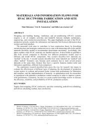
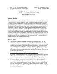
G. Wang, S.F. Li / Theoretical and Applied Fracture Mechanics 42 (2004) 303–316 305ing body <strong>for</strong>ce, the equilibrium equation inside anRVE takes the <strong>for</strong>mrr ¼ 0 8x 2 V ð2ÞAssume that the prescribed tractions on the remoteboundary of the RVE (oV 1 ) are generatedby a constant stress tensor r 1 . Let oV ec denotetraction-free part of a <strong>cohesive</strong> <strong>crack</strong> surface,and let oV pz denote the <strong>cohesive</strong> part of the <strong>crack</strong>surface where constant traction <strong>for</strong>ce t is applied.Using divergence theorem and Eq. (2), it isstraight<strong>for</strong>ward to show thathri ¼ 1 ZrdV ¼ 1 Zfr ðr xÞg T dVV V V V¼ 1 ZZr 1 dV fn ðr xÞg T dSV VoVZecfn ðr xÞg T dSoV pzZ¼ r 1 1fn ðr xÞg T dSV oV pzZ¼ r 1 1x tdSð3ÞV oV pzwhere t is the constant <strong>cohesive</strong> traction.Note that oV pz = oV pz+ [ oV pz and the surfaceareas joV pzþ j¼joV pz j¼ 1 joV 2 pzj, where subscriptÔ+Õ and Ô Õ are used to distinguish upperand lower part of the <strong>crack</strong> surfaces. So the lastterm in Eq. (3) becomesZ1x tdS ¼ 1 V oV pzVZZx t þ dS þoV pzþoV pz¼ 12V x ðtþ þ t ÞjoV pz j¼ 0x t dS!ð4Þwhere t + = t are the <strong>cohesive</strong> tractions actingon oV pz+ and oV pz respectively.There<strong>for</strong>e, the average stress inside the RVEwill equal to remote stressR ¼hri ¼r 1ð5ÞBy superposition, it is straight<strong>for</strong>ward to generatethis result to an RVE with N <strong>cohesive</strong> <strong>crack</strong>s randomlydistributed inside (see Fig. 1),hri ¼r 1 1VX Na¼1ZoV ðaÞpzx t ðaÞ dS ¼ r 1ð6ÞFig. 1. Randomly distributed micro-<strong>crack</strong>s within an RVE.Hence, the averaging theorem follows:Theorem. Suppose1. an elastic representative volume element containsN Barenblatt–Dugdale <strong>penny</strong>-<strong>shaped</strong> <strong>crack</strong>s with<strong>cohesive</strong> tractions in the <strong>cohesive</strong> zones;2. the tractions on the remote boundary of the RVEis generated by a constant stress tensor, i.e.,t 1 = n Æ r 1 and r 1 is constant.Then, macro stress of the RVE equals to the remoteconstant stress, i.e. R = hri = r 1 .3. Penny-<strong>shaped</strong> <strong>crack</strong> under uni<strong>for</strong>m triaxialtensionBe<strong>for</strong>e homogenization, the analytical solutionof three-dimensional (3D) <strong>penny</strong>-<strong>shaped</strong> <strong>crack</strong> inan RVE that is under uni<strong>for</strong>m triaxial tension isoutlined in this section (see Fig. 2).Penny-<strong>shaped</strong> Dugdale <strong>crack</strong> problem has beenstudied by several authors. The early contributionwas made by Keer and Mura, who used the Trescayield criterion to link the <strong>cohesive</strong> strength tomicro yield stress [17]. In their study, only uniaxialtension loading was considered. More recently,
306 G. Wang, S.F. Li / Theoretical and Applied Fracture Mechanics 42 (2004) 303–316where I (2) = d ij e i e j is the second-order identitytensor. By the averaging theorem, it is obvious thatmean macro stress, defined as R m ¼ 1 R 3 kk, equalsapplied remote stress,R m ¼ r 1ð8ÞIn cylindrical coordinate, the traction conditionson the remote boundary oV 1 and symmetric displacementboundary condition are expressed asr zz j oV 1¼ r hh j oV 1¼ r rr j oV 1¼ R m ð9ÞFig. 2. A <strong>penny</strong>-<strong>shaped</strong> <strong>cohesive</strong> <strong>crack</strong> in representativevolume element (the shaded region: <strong>cohesive</strong> zone—yieldedring).Chen and Keer re-examined the problem, and theyobtained general solutions <strong>for</strong> a <strong>penny</strong>-<strong>shaped</strong><strong>cohesive</strong> <strong>crack</strong> under mixed-mode loading [5,6].On the other hand, however, the problem hasnot been thoroughly examined from micromechanicsperspective. For example, the connectionamong the onset value of <strong>cohesive</strong> strength, microyield stress in an RVE, and remote macro stresshas not been made. By examining a <strong>cohesive</strong><strong>penny</strong>-<strong>shaped</strong> <strong>crack</strong> in an RVE, the study providesa link among <strong>cohesive</strong> strength, yield stress of virgin<strong>material</strong>, and remote stresses on the boundaryof an RVE, which provides foundation <strong>for</strong> ensuinghomogenizations.Consider a three-dimensional <strong>penny</strong>-<strong>shaped</strong>Dugdale <strong>crack</strong> of radius a with a ring-<strong>shaped</strong> <strong>cohesive</strong>zone with width b a in an RVE, which maybe viewed as an infinite isotropic space by ‘‘amicro-observer ’’ inside the RVE.Let the outward normal to <strong>crack</strong> surface parallelto Z(X 3 ) axis (see Fig. 2) and uni<strong>for</strong>m triaxialtension stress is applied at the remote boundaryof the RVE, i.e.r 1 ¼ r 1 I ð2Þð7Þu z ðr; h; 0Þ ¼0 <strong>for</strong> b 6 r; 0 6 h 6 2p ð10ÞThe stress distribution on the <strong>crack</strong> surface and<strong>cohesive</strong> zone isr zz ðr; h; 0Þ ¼r 0 Hðr aÞ<strong>for</strong> 0 6 r 6 b; 0 6 h 6 2pð11Þwhere R m is the remote stress, H(r a) is theHeaviside function, and r 0 is the <strong>material</strong>Õs <strong>cohesive</strong>strength, the onset value <strong>for</strong> <strong>crack</strong> opening,and it is different from the micro yielding stress.The problem can be solved via superposition oftwo sub-problems: a trivial problem—an intactRVE in uni<strong>for</strong>m triaxial tension state, i.e. "x2V,r ð0Þzzr ð0Þrz¼ r ð0Þhh¼ r ð0Þrh¼ rð0Þ rr¼ R m ð12Þ¼ rð0Þ zh ¼ 0 ð13Þand a <strong>crack</strong> problem—an RVE with a center <strong>crack</strong>that is subjected to the following boundary conditions(see Fig. 3):r ðcÞzz j oV 1¼ r ðcÞhh j oV 1¼ r ðcÞrr j oV 1¼ 0 ð14Þr ðcÞzz ðr; h; 0Þ ¼ R m þ r 0 Hðr aÞ<strong>for</strong> 0 6 r 6 b; 0 6 h 6 2pð15Þu ðcÞzðr; h; 0Þ ¼0 <strong>for</strong> b 6 r; 0 6 h 6 2p ð16ÞFor the <strong>crack</strong> problem, the <strong>crack</strong> opening displacementcould be solved as8>:2p2p1 v l 1 v l R mR mpffiffiffiffiffiffiffiffiffiffiffiffiffiffib 2 r 2pffiffiffiffiffiffiffiffiffiffiffiffiffiffib 2 r 2R bpffiffiffiffiffiffiffiffiffiffiffiffiffipr 0 ta2 a 2 = ffiffiffiffiffiffiffiffiffiffiffiffiffi t 2 r 2 dt ; 0 < r < aR bpffiffiffiffiffiffiffiffiffiffiffiffiffipr 0 tr2 a 2 = ffiffiffiffiffiffiffiffiffiffiffiffiffi t 2 r 2 dt ; a < r < bð17Þ
G. Wang, S.F. Li / Theoretical and Applied Fracture Mechanics 42 (2004) 303–316 307In the yield ring (z = 0 and a < r < b), stress distributionsare found asr ðcÞzz¼ r 0 R m ð18ÞFig. 3. Illustration of superposition of <strong>cohesive</strong> <strong>crack</strong> problem.rr¼ 1 þ 2v R m 2þ 1 2v2r ðcÞ1 þ a2r 2þ 2v r 0ð19Þr ðcÞhh ¼ 1 þ 2v 2þ 1 2v2r ðcÞrz¼ r ðcÞrhR m1a 2r 2þ 2v r 0ð20Þ¼ rðcÞ zh ¼ 0 ð21Þwhere PoissonÕs ratio v*, to be treated as eitheroverall or matrix <strong>material</strong> property, is unspecifiedat this moment, which may depend on the laterhomogenization procedures.To ensure the stresses at <strong>crack</strong> tip to be finite,the size of the <strong>cohesive</strong> zone a/b, macro stressR m , and the <strong>cohesive</strong> stress r 0 are related throughthe following expression:ab ¼sffiffiffiffiffiffiffiffiffiffiffiffiffiffiR 2 m1r 2 0orR mr 0¼sffiffiffiffiffiffiffiffiffiffiffiffiffi1a 2b 2ð22ÞDenote the projection of traction-free <strong>crack</strong> surfaceonto X 1 X 2 plane as X 1 , and the projectionof the <strong>cohesive</strong> zone (ring shape) as X 2 . The totalvolume of <strong>crack</strong> opening by a single <strong>cohesive</strong> <strong>crack</strong>is the integration of <strong>crack</strong> opening displacementFig. 4. Projection domain of <strong>crack</strong> surface and <strong>cohesive</strong> zone.over the entire projection area, X = X 1 [ X 2 (seeFig. 4). It is readily to show thatZ Z ZV c ¼ ½u z ŠdS ¼ ½u z ŠdS þ ½u z ŠdSXX 1 X 2¼ 8ð1 v Þhib 3 R3l m r 0 ð1 ða=bÞ 2 Þ 3=2¼ 8ð1 v Þa 3 R mqffiffiffiffiffiffiffiffiffiffiffiffiffiffiffiffiffiffiffiffiffiffiffiffiffiffiffi3l 1 ðR m =r 0 Þ 2ð23Þwhere the <strong>crack</strong> opening displacement, COD, isdefined by½u z Š¼u þ zu z¼ 2u z ð24ÞIf one is mainly interested in inelastic de<strong>for</strong>mationof quasi-brittle <strong>material</strong>s, it may be assumed that
308 G. Wang, S.F. Li / Theoretical and Applied Fracture Mechanics 42 (2004) 303–316micro-scale yielding due to hydrostatic stress stateis small-scale yielding: a2 1. For a 6 r 6 b, a2 1.b 2 r 2The total stress distribution within <strong>cohesive</strong> zone(a 6 r 6 b) may be approximated asr ðtÞzzr ðtÞrr¼ r ð0Þzz¼ r ð0Þrrþ r ðcÞzz¼ r 0 ð25Þþ r ðcÞrr¼ 1 2v R m þ r 02r ðtÞhh ¼ rð0Þ hh þ rðcÞ hh ¼ 1r ðtÞrz¼ r ðtÞrh ¼ rðtÞ zh ¼ 02v R m þ 2v r 02ð26Þð27Þð28ÞIt is assumed that inside the <strong>cohesive</strong> zone microplastic yielding is controlled by the Huber–vonMises criterion. There<strong>for</strong>e, one can link the <strong>cohesive</strong>strength, r 0 , with the yield stress of the virgin<strong>material</strong>, r Y ,by12r ðtÞrrr ðtÞzz 2 2þ rðtÞ 2þ rðtÞhhr ðtÞzzrrr ðtÞhh¼ r 2 Yð29ÞSubstitute Eqs. (25)–(27) into (29) and solve <strong>for</strong> r 0 .The following quadratic equation may be obtained:4 r 2 02 r 202 r Yþ 1¼ 0R m R m 1 2v R mð30Þwhich has two roots. The positive root is chosen tolink the <strong>cohesive</strong> stress r 0 with the yield stress r Yof virgin <strong>material</strong> in uniaxial tension,1 þr 0¼R msffiffiffiffiffiffiffiffiffiffiffiffiffiffiffiffiffiffiffiffiffiffiffiffiffiffiffiffiffiffiffiffiffiffiffiffiffiffiffi 24 r Y31 2v R m4ð31Þ4. Effective elastic <strong>material</strong> properties of an RVEOne of the goals of homogenization is to find theeffective <strong>material</strong> properties of an RVE to characterizethe constitutive relation of stress and strainrelation at the macro-level. Conjugate to the macrostress R, the macro strain E is defined through theoverall complementary energy density W c of an RVEE ¼ oW coRð32ÞDefine the effective compliance D of the micro<strong>crack</strong>edRVE throughE ¼ D : R ¼ D : r 1ð33Þwhere the macro stress R = r 1 , according to averagetheorem, is regarded as prescribed. It is notedthat the macro strain of an RVE may not be thevolume average strain, i.e, E 5 hei. FurthermoreEq. (33) may not be a linear relationship, becauseD may depend on R in general, which will be substantializedin later sections.A common strategy <strong>for</strong> homogenization of randomlydistributed defects is to divide the macrostrain E into two parts,E ¼ e ð0Þ þ e ðaÞð34Þwhere e (0) = D:R is known, and D is the elasticcompliance of the corresponding virgin <strong>material</strong>.The second term e (a) is so-called additional straintensor representing the effect of defects. If the relationshipbetween additional strain and macrostress can be found, say e (a) = H:R, where H isthe added compliance due to micro-<strong>crack</strong>s, subsequentlythe effective elastic compliance moduli,D ¼ D þ H, can be deduced.Energy method is applied to find an additionalstrain <strong>for</strong>mula <strong>for</strong> <strong>cohesive</strong> <strong>crack</strong>s. The essenceof energy methods is to find the energy release ina <strong>cohesive</strong> fracture process and hence to find theequivalent reduction of <strong>material</strong> properties. Forelastic <strong>crack</strong>s, the energy release rates were discussedin the classical works of Rice and hisco-worker [3,25,26]. Nevertheless, the energy dissipationprocess of <strong>cohesive</strong> fracture is much morecomplicated than a purely elastic fracture process.It includes energy dissipation from both surfaceseparation and plastic dissipation. A related discussioncan be also found in [18,22,31].Although accurate determination of energy lossduring a <strong>damage</strong> process requires an in-depthunderstanding of the physical process involved,an upper bound estimate may be made based onsimplified assumptions. It is assumed that the totalenergy release of a <strong>cohesive</strong> <strong>crack</strong> is completelyconsumed in surface separation, which may ormay not be true in <strong>cohesive</strong> fracture, because ofplastic dissipation in the <strong>cohesive</strong> zone.
G. Wang, S.F. Li / Theoretical and Applied Fracture Mechanics 42 (2004) 303–316 309Subjected to uni<strong>for</strong>m triaxial loading r 1 =R m I (2) , the total energy release rate of an RVE witha single <strong>penny</strong>-<strong>shaped</strong> <strong>cohesive</strong> micro-<strong>crack</strong> can beestimated asZZR ¼ R m ½u z ŠdS r 0 ½u z ŠdSð35ÞXX 2Carrying out the integration using <strong>crack</strong> displacementsolutions Eqs. (17), the energy release estimatecan be written as following expression:R ¼ 16ð1 qffiffiffiffiffiffiffiffiffiffiffiffiffiffiffiffiffiffiffiffiffiffiffiffiffiffiffiv Þr 23l 0 a3 a1 1 ðR m =r 0 Þ 2 ð36ÞConsider that there are N <strong>penny</strong>-<strong>shaped</strong> <strong>crack</strong>s insidethe RVE. The density of energy release of theRVE is estimated as sum of each <strong>crack</strong> contribution,i.e. R ¼ P Na¼1 R a. Define the <strong>crack</strong> openingvolume fraction asf ¼ XN 4pa 3 a3V bð37Þa¼1where a a is the radius of the ath <strong>crack</strong>, and 4pa 3 a =3is the volume of a sphere with radius a a , and b isthe ratio between the volume of permanent <strong>crack</strong>opening and the volume of total <strong>crack</strong> openingof a <strong>cohesive</strong> <strong>crack</strong>. For simplicity, it is assumedthat this ratio is fixed <strong>for</strong> every <strong>crack</strong> inside anRVE. Obviously, 0 < b
310 G. Wang, S.F. Li / Theoretical and Applied Fracture Mechanics 42 (2004) 303–316D ¼ 13K E1 þ 12l E2ð46ÞH ¼ðh 1 þ h 2 ÞE 1 þ h 2 E 2ð47Þwhere E 1 ¼ 1 3 Ið2Þ I ð2Þ , E 2 ¼ 1 3 Ið2Þ I ð2Þ þ I ð4sÞ .Since the traction stress state on the remoteboundary of the RVE is hydrostatic, H tensor inEq. (44) cannot be uniquely determined in thiscase. In<strong>for</strong>mation carried in Eq. (43) is only volumetricand admits only one scalar relation,D : R m I ð2Þ ¼ðD þ HÞ : R m I ð2Þð48ÞConsider Eq. (34) and identities E 1 : I (2) = I (2) andE 2 : I (2) = 0. By virtue of Eqs. (41) and (48), itcan be shown that13K ¼ 13K þðh 1 þ h 2 Þ¼ 13K þ 4ð1 vÞ fqffiffiffiffiffiffiffiffiffiffiffiffiffiffiffiffiffiffiffiffiffiffiffiffiffiffiffið49Þ3bpl1 ðR m =r 0 Þ 2There are two unknowns, K and l, or equivalentlyh 1 and h 2 in Eq. (49). Additional condition isneeded to uniquely determine D or H. Imposethe restriction that the relative reduction of theshear modulus is the same as that of the bulkmodulus,KK ¼ l ð50ÞlThis restriction further guarantees the positive definitenessof the overall strain energy.Consider the relations13K ¼ 1 2vE12l ¼ 1 þ vEandand13K ¼ 1 2vE12l ¼ 1 þ vEð51ÞA direct consequence of Eq. (50) is v ¼ v, so13K ¼ 1 1 2v¼ 1 1 2v2l 1 þ v 2l 1 þ v13K ¼ 1 ð52Þ1 2v2l 1 þ vKK ¼ l l ¼ 1 8ð1 v 2 Þ fqffiffiffiffiffiffiffiffiffiffiffiffiffiffiffiffiffiffiffiffiffiffiffiffiffiffiffi3bpð1 2vÞ1 ðR m =r 0 Þ 25. Micro-<strong>cohesive</strong>-<strong>crack</strong> <strong>damage</strong> <strong>model</strong>ð53ÞHomogenization of nonlinear problems is oftendifficult. Without proper statistical closure, averagingalong may not be sufficient to provide sensibleresults. In this paper, it is postulated that thereis a limit <strong>for</strong> the amount of distortional energy thata given <strong>material</strong> ensemble can store. This reflectsin the following hypothesis on the condition ofmacro-yielding:The macroscopic yielding of an RVE begins whenthe distortional strain energy density of an RVEreaches to a threshold. In other words, the maximumelastic distortional energy of an RVE is a <strong>material</strong>constant,U d 6 U crdð54ÞIt is noted that above criterion is a reminiscenceof the HenckyÕs maximum distortional energyprinciple in traditional infinitesimal plasticity.The criterion can be calibrated using an uniaxialtension test of the virgin <strong>material</strong>U crd ¼ 16l r2 Yð55ÞDefine the macro deviatoric stress tensor and itssecond invariant asR 0 ¼ R 1R 3 kkI ð2Þ ð56ÞJ 2 ¼ 1 2 R0 : R 0ð57Þand the equivalent macro stress R eq is defined aspR eq ¼ffiffiffiffiffiffiffi3J 2ð58ÞIn a real <strong>damage</strong> evolution process, the above criteriatake the following <strong>for</strong>m:U d ¼ J 22l ¼ R2 eq6l 6 U crdð59ÞSo the criterion of the maximum distortional energydensity of an RVE becomeswhich, when substituted into Eq. (49), leads to theestimates of effective elastic moduliR 2 eqr 2 Y¼ l lð60Þ
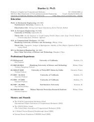
G. Wang, S.F. Li / Theoretical and Applied Fracture Mechanics 42 (2004) 303–316 311Using Eq. (53), one may derive the following effectiveyielding potential:WðR eq ; R m ; qÞ ¼ R2 eqþ 8ð1 v2 Þr 2 Y3bpð1 2vÞf qffiffiffiffiffiffiffiffiffiffiffiffiffiffiffiffiffiffiffiffiffiffiffiffiffiffiffi1 ¼ 0 ð61Þ1 ðR m =r 0 Þ 2where R eq and R m are defined as the equivalentmacro stress and mean macro stress, and q representsthe other internal variables, which may beimplicitly embedded in r Y .In terms of the stress ratio R m /r Y , the effectiveyielding potential function of plastic flow W canbe recast asWðR eq ; R m ; qÞ¼ R2 eqþ 8ð1 v2 Þfr 2 Y3bpð1 2vÞrffiffiffiffiffiffiffiffiffiffiffiffiffiffiffiffiffiffiffiffiffiffiffiffiffiffiffiffiffi 24r1 þYð1 2vÞR m3 0r ffiffiffiffiffiffiffiffiffiffiffiffiffiffiffiffiffiffiffiffiffiffiffiffiffiffiffiffiffi! 212@4r1 þY3 16Að12vÞR m121 ¼ 0ð62ÞThe newly derived pressure-sensitive yieldingfunction W, is displayed in Fig. 5 with differentPoissonÕs ratios. It should be mentioned that theself-consistent scheme based <strong>damage</strong> <strong>model</strong> W willfail at v = 0.5, since <strong>for</strong> incompressible <strong>material</strong>s,uni<strong>for</strong>m triaxial tension load will not be able toproduce dilatational strain energy.In Fig. 6, the <strong>cohesive</strong> <strong>damage</strong> <strong>model</strong> is juxtaposedwith the popular Gurson <strong>model</strong> [12], whoseeffective yield function takes the following <strong>for</strong>m:U ¼ R2 eqþ 2f cosh 3 R mð1 þ f 2 Þ¼0 ð63Þr 2 Y2 r YBoth yield functions will reduce to classical J 2plasticity when f = 0. However, it is worth noticingthat <strong>for</strong> the limit case of infinitesimal amount of<strong>damage</strong> (i.e. f ! 0), the proposed <strong>cohesive</strong> <strong>damage</strong><strong>model</strong> predicts yielding of <strong>material</strong> when the stressratio of hydrostatic stress and the <strong>cohesive</strong> strength,or equivalently the ratio of hydrostatic stress andtrue yield stress, approaches a finite value, i.e.R mR m 4! 1 or ! pffiffiffiffiffið64Þr 0 r Y 12 ð1 2vÞFor Gurson <strong>model</strong>, when the amount of <strong>damage</strong> isinfinitesimal the <strong>material</strong> will not yield unless thehydrostatic stress becomes infinite. The asymptoticyielding potentials <strong>for</strong> infinitesimal <strong>damage</strong> arehighlighted as dashed lines in Fig. 6(c) and (d).Obviously, the Gurson <strong>model</strong> is not realistic, becauseany <strong>material</strong> will fail when the remote loadexceeds the <strong>material</strong>Õs theoretical strength.In the followings, features of the present <strong>model</strong>will be explored in the framework of continuummechanics. The macro response the reversible partof effective constitutive relation is characterized asa nonlinear elasticity, whereas the irreversible partof effective constitutive relation is a <strong>for</strong>m of pressure-sensitiveplasticity. The rate <strong>for</strong>m of constitutiverelation <strong>for</strong> <strong>damage</strong>d <strong>material</strong>s is written as_R ¼ C : ð E _ pE _ Þ ð65Þwhere C is the effective elastic moduli andC ¼ D 1 p; E _ and E _ are the average rate of totalde<strong>for</strong>mation and the average rate of plastic de<strong>for</strong>mationrespectively.The macro plastic flow direction may be givenby the associative rule_E p ¼ kN _ ð66Þwhere N is the normal of yield surface in stressspaceN ¼ oWð67ÞoRand the plastic multiplier k _ can be determined byconsistency condition as usual,hN : C : Ei_k ¼_ ð68ÞN : C : N W q Nwhere W q ¼ oW , h Æ iis the Macauley bracket, and qoqare internal variables whose evolutions are assumedto be governed by_q ¼ _ khðR; qÞð69ÞThe <strong>damage</strong> evolution law <strong>for</strong> micro-<strong>crack</strong>s in a<strong>cohesive</strong> elastic environment may be significantlydifferent from that of voids in a perfectly viscoplasticenvironment. For this moment, conventional
312 G. Wang, S.F. Li / Theoretical and Applied Fracture Mechanics 42 (2004) 303–316Fig. 5. Cohesive micro-<strong>crack</strong> <strong>damage</strong> <strong>model</strong>, W(R eq , R m , q), with different PoissonÕs ratios (b = 1/3).<strong>damage</strong> evolution law is adopted. Let the volumeof the RVE be denoted as V = V m + V c , whereV c is the <strong>crack</strong> opening volume and V m is the volumeof matrix. Assuming the total rate change ofthe <strong>crack</strong> volume is proportional to the volume ratechange in an RVE, i.e._V c ¼ c _Vð70Þwhere c is the proportionality constant. Then_f ¼ d dtV cV¼ðcf Þ _ VV ¼ðc f Þtraceð _ EÞ ð71ÞAssume a specimen is originally intact (i.e. f = 0),and it is subjected to an uniaxial tension test underdisplacement control. The onset of <strong>material</strong> <strong>damage</strong>,which is physically initiation and propagationof micro-<strong>cohesive</strong>-<strong>crack</strong>s, will occur after the specimenfirst reaches its yield limit (r Y , e Y ).Let r and e denote axial stress and axial strainof the specimen, it is obvious that R eq = r,R m = r/3 and traceð EÞ¼ð1 _ 2vÞ_e. Eq. (71) isused to describe post-elastic <strong>damage</strong> evolutionprocess, and <strong>for</strong> the purpose of illustration onecan simply choose c = 1. Integrate the rate <strong>for</strong>m,volume fraction f could there<strong>for</strong>e be deduced froma given axial strain e,1f ¼ 1ð72Þexpðð1 2vÞðe e Y ÞÞThe corresponding axial stress during persistentplastic loading could be derived via solving yieldingpotential functions W(r, e) =0orU(r, e)=0.In Figs. 7 and 8, the predicted post-elastic <strong>material</strong>behaviors of the present <strong>model</strong> and Gurson<strong>model</strong> are plotted <strong>for</strong> various PoissonÕs ratios.For clarity, initial yield strain e Y is neglected in
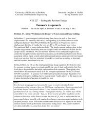
314 G. Wang, S.F. Li / Theoretical and Applied Fracture Mechanics 42 (2004) 303–316Fig. 7. Cohesive <strong>model</strong> prediction of axial stress and strain <strong>for</strong>different PoissonÕs ratios.ratio, it is still able to capture softening behavior atthe nearly incompressible limit.To account <strong>for</strong> the rapid void coalescence atfailure, Tvergaard and Needleman extended originalGurson <strong>model</strong> by introducing parameters q 1 ,q 2 and f*. As a modification of Eq. (63), the yieldingpotential function of Gurson–Tvergaard–Needleman(GTN) <strong>model</strong> [30] is written asU ¼ R2 eqþ 2qr 2 1 f cosh 3q 2 R mð1 þ q 2 1Y2 r f 2 Þ¼0Yð73Þwhere f* is specified as a piecewise function of f via8f<strong>for</strong> f 6 f c>:1=q 1 <strong>for</strong> f f < fð74ÞNote that f c and f f are volume fractions at onset ofvoid coalescence and total failure respectively.They are regarded as <strong>material</strong> constant and needto be specified. It is seen that as volume fraction fgrows towards its failure value f f and f* approaches1/q 1 the yield surface <strong>for</strong> macro stresses shrinks toa point, so <strong>material</strong> is ‘‘preprogrammed’’ to fail atf = f f . So in GTN <strong>model</strong>, effects of void coalescenceand total failure are addressed by scaling and interpolation,while failure prediction is embedded inthe <strong>cohesive</strong> <strong>crack</strong>ed <strong>model</strong>.Fig. 8. Gurson <strong>model</strong> prediction of axial stress and strain <strong>for</strong>different PoissonÕs ratios.Table 1Predicted critical volume fraction <strong>for</strong> different PoissonÕs ratiosv 0.100 0.200 0.300 0.400 0.499f f 0.632 0.489 0.343 0.186 0.002volume fraction change throughout the tensiontest is very tinny according to Eq. (72). Gurson<strong>model</strong> reduces to J 2 plasticity and fail to predictany <strong>damage</strong> effect. While <strong>for</strong> the present <strong>model</strong>,because yielding potentials also depend on PoissonÕsFig. 9. Comparison of <strong>model</strong> predictions (v = 0.3).
G. Wang, S.F. Li / Theoretical and Applied Fracture Mechanics 42 (2004) 303–316 315Predictions of all three <strong>model</strong>s are plotted inFig. 9 <strong>for</strong> PoissonÕs ratio v = 0.3. For simply illustrativepurpose, parameters <strong>for</strong> GTN <strong>model</strong> arechosen as q 1 = 1.5, q 2 =1, and f f = 0.343, f c =f f /3. It is noted that above f f value is chosen onpurposely to be the same as that predicted by<strong>cohesive</strong> <strong>crack</strong> <strong>model</strong>. Although GTN matches<strong>cohesive</strong> <strong>model</strong> at both ends (of course), itsundergoes an abrupt change once f exceeds f c .Damage process towards failure is piecewise quasi-linearand catastrophic failure effect is stillabsent.6. Concluding remarksIn this paper, a novel micromechanics based<strong>damage</strong> <strong>model</strong> is proposed <strong>for</strong> addressing failuremechanism of defected solids with randomly distributed<strong>penny</strong>-<strong>shaped</strong> <strong>cohesive</strong> micro-<strong>crack</strong>s(Barenblatt–Dugdale type). The distinguished featuresof the present <strong>cohesive</strong> <strong>crack</strong> <strong>damage</strong> <strong>model</strong>sare:• Homogenized macro-constitutive relations aredifferent from the micro-constitutive relations:the reversible part of macro-constitutive relationis nonlinear elastic versus the linear elasticbehaviors at micro-level; the irreversible part ofmacro-constitutive relation is a <strong>for</strong>m of pressuresensitive plasticity versus the Huber–von Misesplasticity or <strong>cohesive</strong> laws at micro-level.• In <strong>cohesive</strong> <strong>damage</strong> <strong>model</strong>s, the effective yieldsurfaces depend on <strong>material</strong>s PoissonÕs ratio;whereas in the Gurson <strong>model</strong>, no such dependencecan be predicted, because of its assumptionof RVE is perfectly plastic. Different asymptoticyield surfaces are also observed <strong>for</strong> the case ofinfinitesimal <strong>damage</strong>.• Comparison of the present <strong>model</strong> with Gurson<strong>model</strong> and Gurson–Tvergaard–Needleman(GTN) <strong>model</strong> <strong>for</strong> a simple loading shows that,the present <strong>model</strong> can predict a critical volumefraction at which complete failure of <strong>material</strong>would occur. It can <strong>model</strong> and predict post elastic<strong>material</strong> degradation and catastrophic failuredue to <strong>cohesive</strong> micro-<strong>crack</strong> growth andcoalescence.The key step in the <strong>model</strong> development is howto accurately determine the energy release contributionto the <strong>material</strong> <strong>damage</strong> process. The energyrelease in nonlinear fracture mechanical process isconsumed in several different dissipation processes,e.g. surface separation, dislocation movement andhence plastic dissipation, heat conduction, andmay be even phase trans<strong>for</strong>mation, etc. In fact,both Kfouri [18] and Wnuk [31] have studiedenergy release caused by the extension of Dugdale-BCS <strong>crack</strong>s in a two-dimensional space. To incorporatethose available results into the current<strong>for</strong>mulation, an in-depth study may be needed torefine the <strong>damage</strong> <strong>model</strong>s proposed here. A detailedcompanied mathematical exposition on<strong>cohesive</strong> <strong>damage</strong> <strong>model</strong> is reported in Li andWang [21].AcknowledgmentThis work is supported by a research fund toProfessor Shaofan Li by the committee on researchin University of Cali<strong>for</strong>nia at Berkeley,which is appreciated.References[1] G.I. Barenblatt, The <strong>for</strong>mation of equilibrium <strong>crack</strong>sduring brittle fracture, Journal of Applied Mathematics& Mechanics 23 (1959) 622–636, English translation fromPMM 23 (1959) 434–444.[2] G.I. Barenblatt, Mathematical Theory of EquilibriumCracks in Brittle Fracture, Advances in Applied Mechanics,vol. 7, Academic Press, 1962, pp. 55–129.[3] B. Budiansky, J.R. Rice, Conservation laws and energyrelease rates, Journal of Applied Mechanics 26 (1973) 201–203.[4] B. Budiansky, R.J. OÕConnell, Elastic moduli of a <strong>crack</strong>edsolid, International Journal of Solids and Structures 12(1976) 81–97.[5] W.R. Chen, L.M. Keer, Fatigue <strong>crack</strong> growth in mixedmode loading, ASME Journal of Engineering Materialsand Technology 113 (1991) 222–227.[6] W.R. Chen, L.M. Keer, Mixed-mode fatigue <strong>crack</strong> propagationof <strong>penny</strong>-<strong>shaped</strong> <strong>crack</strong>s, ASME Journal of EngineeringMaterials and Technology 115 (1993) 365–372.[7] D.S. Dugdale, Yielding of steel sheets containing slits,Journal of Mechanics and Physics of Solids 8 (1960) 100–104.
316 G. Wang, S.F. Li / Theoretical and Applied Fracture Mechanics 42 (2004) 303–316[8] J.D. Duva, J.W. Hutchinson, Constitutive potentials <strong>for</strong>dilutely voided nonlinear <strong>material</strong>s, Mechanics of Materials3 (1984) 41–54.[9] N. Fleck, Brittle fracture due to an array of micro<strong>crack</strong>s,Proceedings of Royal Society of London Series A 432(1991) 55–76.[10] M. Gologanu, J.B. Leblond, J. Devaux, Recent extensionsof GursonÕs <strong>model</strong> <strong>for</strong> porous ductile metals, in: P. Suquet(Ed.), Continuum Micromechanics, Springer-Verlag, 1995,pp. 61–130.[11] A.L. Gurson, Plastic flow and fracture behavior ofductile <strong>material</strong>s incorporating void nucleation, growthand interaction, Ph.D. Thesis, Brown University, RI,1975.[12] A.L. Gurson, Continuum theory of ductile rupture by voidnucleation and growth: Part I. Yield criteria and flow rules<strong>for</strong> porous ductile <strong>material</strong>s, Journal of EngineeringMaterials and Technology 99 (1977) 2–15.[13] R. Hill, Theory of mechanical properties of fiber-strengthened<strong>material</strong>s—III: Self-consistent <strong>model</strong>, Journal ofthe Mechanics and Physics of Solids 13 (1965) 189–198.[14] R. Hill, A self-consistent mechanics of composite <strong>material</strong>s,Journal of the Mechanics and Physics of Solids 13(1965) 213–222.[15] J.W. Hutchinson, Crack tip shielding by micro-<strong>crack</strong>ing inbrittle solids, Acta Metallurgica 35 (1987) 1605–1619.[16] M. Kachanov, Elastic solids with many <strong>crack</strong>s and relatedproblems, in: J.W. Hutchinson, T. Wu (Eds.), Advances inApplied Mechanics, vol. 32, Academic Press, New York,1994, pp. 259–445.[17] L.M. Keer, T. Mura, Stationary <strong>crack</strong> and continuousdistributions of dislocations, in: Proceedings of The FirstInternational Conference on Fracture, vol. 1, The JapaneseSociety <strong>for</strong> Strength and Fracture of Materials, 1965,pp. 99–115.[18] A.P. Kfouri, Crack separation energy-rates <strong>for</strong> the DBCS<strong>model</strong> under biaxial modes of loading, Journal of Mechanicsand Physics of Solids 27 (1979) 135–150.[19] D. Krajcinovic, Damage Mechanics, Elsevier, Amsterdam–New York, 1996.[20] F.A. McClintock, A criterion <strong>for</strong> ductile fracture by thegrowth of holes, ASME Journal of Applied Mechanics 35(1968) 363–371.[21] S.F. Li, G. Wang, On <strong>damage</strong> theory of a <strong>cohesive</strong>medium, International Journal of Engineering Science 42(2004) 861–885.[22] T. Mura, Micromechanics of Defects in Solids, MartinusNijhoff Publishers, Dordrecht, 1987.[23] S. Nemat-Nasser, M. Hori, Micromechanics: OverallProperties of Heterogeneous Materials, 2nd ed., Elsevier,Amsterdam–Lausanne–New York–Ox<strong>for</strong>d, 1999.[24] T. Pardoen, J.W. Hutchinson, An extended <strong>model</strong> <strong>for</strong> voidgrowth and coalescence, Journal of the Mechanics andPhysics of Solids 48 (2000) 2467–2512.[25] J.R. Rice, A path independent integral and the approximateanalysis of strain concentration by notches and <strong>crack</strong>s,ASME Journal of Applied Mechanics 35 (1968) 379–386.[26] J.R. Rice, Mathematical analysis in the mechanics offracture, in: H. Liebowitz (Ed.), Fracture: An AdvancedTreatise, vol. 2, Academic Press, 1968, pp. 191–311.[27] V. Tvergaard, Influence of voids on shear band instabilitiesunder plane strain conditions, International Journal ofFracture 17 (1981) 389–407.[28] V. Tvergaard, On localization in ductile <strong>material</strong>s containingvoids, International Journal of Fracture 18 (1982) 237–251.[29] V. Tvergaard, Material failure by void growth to coalescence,in: J.W. Hutchinson, T.Y. Wu (Eds.), Advances inApplied Mechanics, vol. 27, Academic Press, New York,1990, pp. 83–151.[30] V. Tvergaard, A. Needleman, Analysis of the cop-conefracture in a round tensile bar, Acta Metallurgica 32 (1984)157–169.[31] M.P. Wnuk, Mathematical <strong>model</strong>ing of nonlinear phenomenain fracture mechanics, in: M.P. Wnuk (Ed.),Nonlinear Fracture Mechanics, Springer-Verlag, Wien–New York, 1990, pp. 359–451.