Lab Experiment No. 4: Introduction to the Principle of Superposition
Lab Experiment No. 4: Introduction to the Principle of Superposition
Lab Experiment No. 4: Introduction to the Principle of Superposition

You also want an ePaper? Increase the reach of your titles
YUMPU automatically turns print PDFs into web optimized ePapers that Google loves.
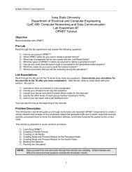
EE 442 <strong>Lab</strong>ora<strong>to</strong>ry <strong>Experiment</strong> 4<strong>Introduction</strong> <strong>to</strong> <strong>the</strong> <strong>Principle</strong> <strong>of</strong> <strong>Superposition</strong>DC Supply+20 V tapAmmeterR1A14.7k12VdcV1CommonR210k12VdcV2-20 V tapAmmeterA2R333kFigure 6 <strong>Lab</strong>ora<strong>to</strong>ry version <strong>of</strong> <strong>the</strong> circuit in Figure 38. What does <strong>the</strong> circuit arrangement <strong>of</strong> Figure 6 accomplish in terms<strong>of</strong> <strong>the</strong> original circuit?9. Energize <strong>the</strong> circuit given in Figure 6 and <strong>the</strong>n measure and record<strong>the</strong> following data:a. Ammeter readings A 1 and A 2 (compare with prelimcalculations)A 1 = __________A 2 = __________b. Voltage across <strong>the</strong> 10 kΩ resis<strong>to</strong>rV 10 kΩ = __________10. Turn <strong>the</strong> DC supply <strong>of</strong>f, but before dismantling <strong>the</strong> circuit, applyKCL and <strong>the</strong> principle <strong>of</strong> superposition by making <strong>the</strong> followingcalculations:a. Add <strong>the</strong> component values <strong>of</strong> i 1 measured in step 6 <strong>to</strong> <strong>the</strong>value <strong>of</strong> i 1 measured in step 9. (Be careful <strong>to</strong> account for <strong>the</strong>signs!) Compare <strong>the</strong> resultant i1 <strong>to</strong> that <strong>of</strong> step 2.7