YGE-U Series Installation and User Manual - Yingli Solar
YGE-U Series Installation and User Manual - Yingli Solar
YGE-U Series Installation and User Manual - Yingli Solar
- No tags were found...

You also want an ePaper? Increase the reach of your titles
YUMPU automatically turns print PDFs into web optimized ePapers that Google loves.
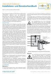
Equipment GroundingThe frame of the PV module, as well as any exposed non-current-carryingmetal parts of fixed equipment that are able to become energized by thePV system, must be connected to the equipment grounding conductorin order to prevent electrical shock. Refer to section 250 of the NEC forspecific instructions on grounding. Even when applicable regulations,code requirements, <strong>and</strong> st<strong>and</strong>ards do not require safety-relatedgrounding, <strong>Yingli</strong> <strong>Solar</strong> recommends grounding all PV module frames inorder to ensure the voltage between electrically conductive equipment<strong>and</strong> earth ground is zero in all circumstances. A PV module with exposedconductive parts is considered to be in compliance with UL 1703 onlywhen it is electrically grounded in accordance with the instructionspresented below <strong>and</strong> the requirements of the National Electrical Code.Proper equipment grounding is achieved by bonding all exposed noncurrent-carryingmetal equipment continuously to one another using anappropriately sized equipment grounding conductor (EGC) or rackingsystem that can be used for integrated grounding (see Option C inGrounding Methods below).<strong>Yingli</strong> <strong>Solar</strong> PV modules employ a coated aluminum frame for corrosionresistance. In order to properly ground the module frame, the coatingmust be penetrated.Grounding wire use copper wire with minimum 12 AWG insulated for aminimum 90 ºC.The potential for corrosion due to the electrochemical action betweendissimilar metals in contact is minimized if the electrochemical voltagepotential between the dissimilar metals is low. The grounding methodmust not result in the direct contact of dissimilar metals with thealuminum frame of the PV module that will result in galvanic corrosion.An addendum to UL 1703 recommends metal combinations not exceedan electrochemical potential difference of 0.5 Volts.The frame rails have pre-drilled holes marked with a grounding sign,as illustrated in Figure 7. These holes should be used for groundingpurposes <strong>and</strong> must not be used for mounting the PV modules. Do notdrill additional holes into the frame rails.Where common grounding hardware (nuts, bolts, star washers,spilt-ring lock washers, flat washers <strong>and</strong> the like) is used to attach alisted grounding/bonding device, the attachment must be made inconformance with the grounding device manufacturer’s instructions.be attached at a designated grounding hole location using #10stainless steel hardware. A stainless steel toothed lock washer or KEPSnut is required to adequately engage the frame <strong>and</strong> penetrate thenonconductive coating. The screw holding the appropriately sizedEGC in place must firmly clamp the EGC in order to establish a reliableelectrical bond.AluminumFrameEquipmentGroundingConductorFigure 8: Grounding lug detailOption B: Screw AssemblyPV LaminateBacking NutToothed Lock Washer or KEPS NutGrounding LugScrew1. A grounding screw assembly must be attached at a designatedgrounding hole location using only stainless steel hardware. Insert a#10 stainless steel screw first through the stainless steel cup washer,<strong>and</strong> then through the grounding hole.2. Loosely engage a stainless steel backing nut <strong>and</strong> toothed lock washerto the screw.3. Bend the EGC into an omega (Ω) shape to tightly fit between thepartially installed screw head <strong>and</strong> cup washer. The EGC shall beexclusively in contact with stainless steel.4. Tighten the screw to 35 in-lbf (4 N∙m) torque. The toothed lock washershould be visibly engaged to the frame.5. Route the appropriately sized EGC in such a way as to avoid contactwith the aluminum module frame.PV LaminateGrounding Holesø0.236in (6mm)AluminumFrameEquipmentGroundingConductorBacking NutToothed Lock Washer or KEPS NutCup WasherScrewFigure 7: Grounding hole detailThe following grounding methods are available:Option A: Grounding LugsManufacturer Part Number Material Tightening TorqueILSCO GBL-4DBT Tin-plated copper 20 to 25 in-lbf(2.3 to 2.6 N∙m)Figure 9: Grounding screw assembly detailOption C: Racking Manufacturer IntegratedGrounding Methods<strong>Yingli</strong> <strong>Solar</strong> PV modules can be grounded by bonding PV modules toa grounded racking system. Integrated grounding methods must becertified to UL 1703 or 2703 for grounding PV modules <strong>and</strong> must beinstalled in accordance with the specified instructions of their respectivemanufacturers.Burndy ® CL501-TN Tin-plated copper 20-25 in-lbf(2.3 to 2.6 N∙m)Tyco ElectronicsSolKlip1954381-4Nickel <strong>and</strong>tin-plated copper15 +4.4/-1.7 in-lbf(1.7+0.5/-0.2 N∙m)Table 2: Grounding lug specifications<strong>Installation</strong> of grounding lugs must be in accordance with the specifiedinstructions of the respective manufacturers. A grounding lug must<strong>Yingli</strong> <strong>Solar</strong> PV Modules, <strong>Installation</strong> <strong>and</strong> <strong>User</strong> <strong>Manual</strong> / page 4
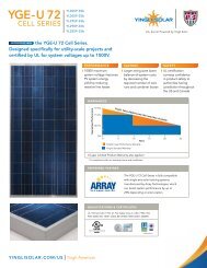
YINGLI SOLARModule SupplementRevision Date September 1, 2012 | Applicable for products rated to 1000 Volts in the United States <strong>and</strong> Canada.This supplement refers to modules of the following types:FAMILY <strong>YGE</strong> 60 Cell SERIES <strong>YGE</strong> 72 Cell SERIESTYPEYL230P-29bYL235P-29bYL240P-29bYL245P-29bYL250P-29bYL255P-29bYL260P-29bYL280P-35bYL285P-35bYL290P-35bYL295P-35bYL300P-35bYL305P-35bMOUNTING REQUIREMENTSMounting Method Option A: Bolts or clampsMounting Method Option B: PanelClaw Attachment SystemModules that RequireFour (4) Connection Points<strong>YGE</strong> 60 Cell SERIES<strong>YGE</strong> 72 Cell SERIES*The Following Modules Require Six (6)Connection Points for <strong>Installation</strong>s thatExceed 50 psf (2400 Pa) Loading<strong>YGE</strong> 72 Cell SERIESPanelClaw Approved Modules<strong>YGE</strong> 60 Cell SERIES* Connections are required at the four outer mounting holesELECTRICAL CHARACTERISTICSNameplate ratings are average values. The electrical characteristics are within +/- 10 percent of the indicated values of Isc, Voc, <strong>and</strong> Pmax under St<strong>and</strong>ardTest Conditions (irradiance of 1000 W/m 2 , AM 1.5 spectrum, <strong>and</strong> a cell temperature of 25ºC). Refer to module datasheets for specific power outputtolerance.ModulefamilyModuletypePoweroutputVoltage atPmaxCurrent atPmaxOpen-circuitvoltageShort-circuitcurrentMax. DC systemvoltageMax. series fuseratingPmax Vmpp Impp Voc Isc[W] [V] [A] [V] [A] [V] [A]YL260P-29b 260 30.9 8.41 38.9 8.98 1000 15YL255P-29b 255 30.6 8.32 38.7 8.88 1000 15<strong>YGE</strong> 60 CellSERIESYL250P-29b 250 30.4 8.24 38.4 8.79 1000 15YL245P-29b 245 30.2 8.11 37.8 8.63 1000 15YL240P-29b 240 29.5 8.14 37.5 8.65 1000 15YL235P-29b 235 29.5 7.97 37.0 8.54 1000 15YL230P-29b 230 29.5 7.80 37.0 8.40 1000 15YL305P-35b 305 37.0 8.25 46.3 8.87 1000 15YL300P-35b 300 36.7 8.17 46.3 8.77 1000 15<strong>YGE</strong> 72 CellSERIESYL295P-35b 295 36.3 8.12 45.4 8.63 1000 15YL290P-35b 290 35.8 8.10 45.3 8.62 1000 15YL285P-35b 285 35.5 8.02 45.0 8.50 1000 15YL280P-35b 280 35.5 7.89 45.0 8.35 1000 15<strong>Yingli</strong> <strong>Solar</strong> PV Modules, <strong>Installation</strong> <strong>and</strong> <strong>User</strong> <strong>Manual</strong> / page 7
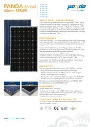
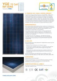
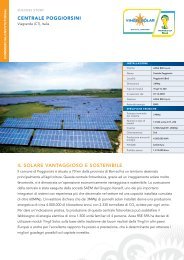
AAREAR AND SIDE VIEW DIMENSIONS OF MODULE SERIESUNITS: INCH (mm)<strong>YGE</strong> 60 Cell SERIES<strong>YGE</strong> 72 Cell SERIES3.94 (100)3.94 (100)Grounding holes6–ø0.236 (6)38.98 (990)37.24 (946) 1.57 (40)43.31 (1100)38.07 (967)64.96 (1650)64.96 (1650)3.94 (100) 3.94 (100)38.98 (990)37.24 (946) 1.97 (50)47.24 (1200)22.72 (577) 16.02 (408)77.56 (1970)77.56 (1970)Mounting holes4–0.256x0.315 (6.5x8)Grounding holes6–ø0.236 (6)22.72 (577)2.17 (55)Drainage holes8–0.12x0.315 (3x8)BBBB3.94 (100)27.44 (697)2.17 (55)Mounting holes6–0.256x0.315 (6.5x8)Drainage holes8–0.12x0.315 (3x8)AA3.94 (100)<strong>YGE</strong> 72 CellFrame Cross Section0.47 (12)<strong>YGE</strong> 60 CellFrame Cross Section0.47 (12)LegendLegendGrounding holesMounting holesDrainage holesMounting tolerance1.97 (50)SECTION A–A1.57 (40)SECTION B–B1.26 (32)1.26 (32)<strong>Yingli</strong> <strong>Solar</strong> PV Modules, <strong>Installation</strong> <strong>and</strong> <strong>User</strong> <strong>Manual</strong> / page 8