Lecture notes for Steel Structures II. Solved Examples by Dr. Kovács ...
Lecture notes for Steel Structures II. Solved Examples by Dr. Kovács ...
Lecture notes for Steel Structures II. Solved Examples by Dr. Kovács ...
- No tags were found...

Create successful ePaper yourself
Turn your PDF publications into a flip-book with our unique Google optimized e-Paper software.
<strong>Lecture</strong> <strong>notes</strong> <strong>for</strong> <strong>Steel</strong> <strong>Structures</strong> <strong>II</strong>.<strong>Solved</strong> <strong>Examples</strong><strong>by</strong><strong>Dr</strong>. Kovács Nauzika2008. February
Contents:1. N, M and N+M resistance of cross-sections belong to class 4.2. Design of column under ex-centric (N+M) compression3. K joints4. Design of bolted connections subjected to tension and bending5. Design of bolted connections subjected to bending and shear
1. N, M and N+M resistance of cross-sections belong to class 4.Design resistance <strong>for</strong> uni<strong>for</strong>m compressionThe design resistance of cross-section <strong>for</strong> uni<strong>for</strong>m compressionfollows:NNc,Rdc,RdA⋅fy=γM 0<strong>for</strong> class 1,2 and 3cross-sectionsAeff⋅ fy=γ<strong>for</strong> class 4 cross-sectionsM 0where A : is the gross cross-sectional area,A : is the effective cross-sectional area.effN ,shall be determined asc RdThe reduction due to holes of fasteners is no need to be taken into consideration.This cross-sectional type behaviour of the compression members quite rarely occurs inpractical members, since they usually have slender members, when the governing failuremode is stability phenomena, as the buckling.Design resistance <strong>for</strong> bendingThe design resistance <strong>for</strong> bending about one principle axis of the cross-sectiondetermined as follows:whereMMMc,Rdc,Rdc,RdWpl⋅ fy=γM 0<strong>for</strong> class 1 and 2 cross-sectionsWel⋅ fy=γM 0<strong>for</strong> class 3cross-sectionsWeff⋅ fy=γ<strong>for</strong> class 4 cross-sectionsM 0Wpl: is the plastic section modulus,Wel: is the elastic section modulus,W : is the effective section modulus.effDesign resistance <strong>for</strong> bending and axial <strong>for</strong>ce – <strong>for</strong> class 4 sectionsThe following criteria should be met:AeffN⋅ fEdy/ γM 0M+Wy,Edeff ,y+ N⋅ fyEd/ γ⋅ eNzM 0M+Wz ,Edeff ,z+ N⋅ fyEd/ γ⋅ eNyM 0≤ 1Mc, Rdshall bewhereeNyand eNz: is the shift of the relevant centroidal axis when the cross section issubjected to compression only,Aeff : is the effective area of the cross-section when subjected touni<strong>for</strong>m compression,Weff ,yandeff , zW : is the effective section modulus of the cross-section whensubjected only to moment about the relevant axis.1
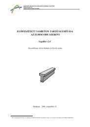
Example 1Find the design resistance of the cross-section shown in Figure 1 under uni<strong>for</strong>mCOMPRESSION! Check the cross-section <strong>for</strong> N Ed= 700 kN axial compression!Grade of the material: S355Geometry of the sectionf 35,5 kN/cm= 2235 / f 235 / 355 0,81yε =y= =320-12a = 4 mm1100-8320-12Figure 1: Geometry of the cross-section.Classification of the cross-sectionFlange: ( cfis distance between the edge of the flange and the fillet weld)cctfffbf tw 320 8= − 2 ⋅ a − = − 2 ⋅ 4 − = 150,3 mm2 2 2 2150,3= = 12,53 > 14 ⋅ε= 14 ⋅ 0,81 = 11,412the flange belongs to Class 4.Web: ( c wis equal to the length of the web between the fillet welds)cctwww= hw− 2 ⋅2 ⋅ a = 1100 − 2 ⋅2 ⋅ 4 = 1088,7 mm1088,7= = 136,1 > 42 ⋅ε= 42 ⋅ 0,81 = 34,28the web belongs to Class 4.The cross-section belongs to Class 4. The effective width of the flange and the web need to beevaluated.Effective width of the flange:Outstand compression element, uni<strong>for</strong>m stress distribution ψ = 1,0 stress ration → kσ= 0, 43buckling factor (Table 4.2).Slenderness of the flange:λcf/ tf=28,4ε ⋅ k12,53=28,4 ⋅ 0,81⋅p=σ0,430,827Reduction factor and beff<strong>for</strong> outstand plate:ρ =λp− 0188 , 0,827 − 0188 ,== 0,9342 2λ 0,827p2
= ρ ⋅ c= 0 , 934 ⋅150,3 = 140,eff f5Effective width of the flanges:cmm= 2 ⋅b+ t + 2 ⋅ a ⋅ 2 = 2 ⋅140,48 + 8 + 2 ⋅ 4 ⋅ 2 = 300,f ,eff eff w3Effective width of the web:Internal compression element, uni<strong>for</strong>m stress distribution ψ = 1,0 stress ration → kσ= 4buckling factor (Table 4.1).Slenderness of the web:b / t cw/ tw1361 ,λ ===28,4ε ⋅ kσ28,4ε ⋅ kσ28,4 ⋅ 0,81⋅Reduction factor and beff<strong>for</strong> internal plate:p=42,945mmρ =λp− 0,055⋅(3 + ψ)2,945 − 0,055⋅(3 + 1)== 0,3142 2λ2,945pbeff = ρ ⋅ b = ρ ⋅ cw= 0 , 314 ⋅1088,7 = 342,1 mmEffective width of the web (lower and upper parts):beff3421 ,cw,eff= + a ⋅ 2 = + 4 ⋅ 2 = 176,7 mm22Effective cross section:A= 2 ⋅ c ⋅ t + 2 ⋅ c ⋅ t = 2 ⋅ 30,03⋅1,2 + 2 ⋅17,67 ⋅ 0,8 100,34 cmeff f ,eff f w,eff w=Compression resistance of the effective cross section:Aeff⋅ fy 100,34 ⋅35,5Nc,Rd= == 3562 kNγ 10 ,M 0Check the resistance of the cross-sectionNNEdc,Rd700= = 0,2 < 10 , → adequate35622176,7171,05176,7171,05300,3Figure 2: Effective cross section.3
Example 2Find the design resistance of the cross-section shown in Figure 1 under uni<strong>for</strong>m BENDING!Check the cross-section <strong>for</strong> M Ed= 1300 kNm bending moment!Grade of the material: S355f 35,5 kN/cm= 2235 / f 235 / 355 0,81yε =y= =Classification of the cross-sectionFlange:Same as it is detailed in Example 1.Web:To classify the web the effective width of the of the flange is required.Effective width of the flange:Same as it is detailed in Example 1.Effective width of the flanges:cf ,eff= 2 ⋅beff+ tw+ 2 ⋅ a ⋅ 2 = 2 ⋅140,48 + 8 + 2 ⋅ 4 ⋅ 2 = 300,3 mmEffective width of the web with the classification:Initially we assume that the gross web is effective. For the classification we need the ratioof normal stresses in the lower ( σ2) and upper ( σ1) fibre of the web, as shown in Figure 3.Area of the gross web and the effective upper flange:2( 30,03 + 32) ⋅1,2 + 110 ⋅ 0,8 162,43 cmA ==The distance of the neutral axis from the upper flange:( 110 + 1,2/2)32 ⋅1,2 ⋅+ 110 ⋅ 0,8 ⋅ 55 − 30 ⋅1,2 ⋅ 0,6z == 55,81 cm162,43Stress ratio:σψ = −σ21z253,62= − = = −0,971z155,24300,3-12σ 1 compressionz = 55,81 cm1100-8z2 = 53,62 cmz1 = 55,24 cm320-12-σ 2 tensionFigure 3: Stress distribution.4
Classification of the web:cctwww= 1100 − 2 ⋅ 4 ⋅2 = 1088,7 mm1088,742 ⋅ ε 42 ⋅ 0,81= = 1361 , >== 97,7280,67 + 0,33⋅ψ 0,67 − 0,33⋅0,971the web belongs to Class 4.Calculation of the web effective width:Internal element, linear stress distribution (Table 4.1)220 > ψ > −1 → k = 7,81−6,29 ⋅ ψ + 9,78⋅ψ = 7,81+6,29 ⋅ 0,971+0,971 = 23,13Slenderness of the web:λb / t=28,4ε ⋅ kσcw/ tw=28,4ε ⋅ k1361 ,=28,4 ⋅ 0,81⋅p=Effective width of the web:λρ =pσσ2313 ,− 0,055(3 + ψ)1,225 − 0,055⋅(3− 0,971)== 0,7422 2λ1,225p1,225In case of element subjected to bending the effective width need to be evaluated only onthe compression side.beff = ρ ⋅bc= ρ ⋅ z1 = 0,742 ⋅552,4 = 410 mmThe effective width of the web besides the upper flange:zf = 0 , 4 ⋅beff + a ⋅ 2 = 0,4 ⋅ 410 + 4 ⋅ 2 = 169,7 mmThe effective width of the web besides the lower flange:za = z2 + 0,6 ⋅beff + a ⋅ 2 = 536,2 + 0,6 ⋅ 410 + 4 ⋅ 2 = 787, 9 mmThe rest of the web:zk = 1100 − zf − za = 1100 −169,7 − 787,9 = 142,4 mmDesign bending resistance of the effective cross-section:A eff= ( 30,03 + 32) ⋅1,2 + (16,97 + 78,79) ⋅ 0,8 = 151,04 cm− 30,03⋅12, ⋅0,6 + 110⋅0,8⋅55−14,24⋅0,8⋅(1697, + 14,24/2) + 32⋅12, ⋅1106,zh == 58,2 cm15104 ,30,03⋅12,=I eff32−15104⋅58 2 =W,I,330,8⋅1100,8⋅14,24+ −3 124306210 cm306210=(58,2 + 1,2)effeff==zmax5155 cm33− 0,8⋅14,24⋅(16,97 + 14,24/2)Weff⋅ fy 5155⋅35,5MC,Rd= = = 183000 kNcm = 1830 kNmγ 10 ,M 022+ 32⋅12, ⋅1106,2−5
Check the resistance of the cross-sectionMMEdc,Rd1300= = 0,711830< 10 , → adequate300,3-12zh = 582 mm1100-8zf =169,7zk =142,4Sza = 787,9 mm320-12Figure 4: Effective cross section.Example 3Check the section of Example 1 when theM Ed= 1300 kNm bending moment are acting together!Calculation of the effective cross-sectionN Ed= 700 kN normal <strong>for</strong>ce and theAeff : is the effective area of the cross-section when subjected to uni<strong>for</strong>m compression,see Example 1.Weff: is the effective section modulus of the cross-section when subjected only tomoment about the relevant axis, see Example 2.Check the resistance of the cross-sectionThe cross section remains symmetrical <strong>for</strong> axial compression, the e = 0AeffNNEdc,RdN⋅ fEdy/ γM 0M+WEdeff+ NEd⋅ e⋅ f / γyzM 0
2. Design of column under excentric (N+M) compressionBasicWhen the resistance of a member is not (or not only) governed <strong>by</strong> the resistance of the crosssectionbut the stability phenomena, the interaction of them has to be analyzed.The interaction of the following failure modes need to be checked:- resistance of the cross-section (<strong>for</strong> normal, shear <strong>for</strong>ces, bending moments andinteraction of them)- global stability phenomena (flexural buckling and lateral-torsional buckling andinteraction of them)- local stability phenomena (local buckling of plates under compression and/or shear)Interaction of the global stability phenomenaThe double symmetric sections the following equations have to be satisfied:NEdNχyγNEdNχzγRkM 1RkM 1+ k+ kyyzyMMy,EdχLTy,EdχLT+ ΔMMγy,RkM 1+ ΔMMγy,RkM 1y,Edy,Ed+ k+ kyzzzMMz , Edz , Ed+ ΔMMγz , RkM 1+ ΔMMγz , RkM 1whereNEd, My , Ed, Mz , Edare the design values of the compression <strong>for</strong>ce and the maximummoment about the y-y and z-z axis along the member, respectivelyΔ My , Ed, Δ Mz , Edare the moment due to the shift of the centroidal axis <strong>for</strong> Class 4sections (see Table 3.14);NRk, My , Rk, Mz , Rkare the characteristic values of the compression and the momentresistance about the y-y and z-z axis along the member,respectively (see Table 3.14);χy, χz,are the reduction factors due to flexural buckling;χLTis the reduction factor due to lateral-torsional bucklingk , k , k , k are the interaction factors (see Table 3.15-3.16);yyyzzyzzz , Edz , Ed≤ 1≤ 1Class 1 2 3 4A i A A A A effW y W pl,y W pl,y W el,y W eff,yW z W pl,z W pl,z W el,z W eff,zΔM y,Ed0 0 0 e N,y N EdΔM z,Ed0 0 0 e N,z N EdN =Rk= fyAi; My, Rk= fyWy; Mz , RkTable 3.14.: The characteristic values of the resistances and the ΔM10fyWz
The simplified method to evaluate the interaction factors:Interactionfactorsk yyk yzk zyTypeofsectionIorRHSIorRHSIorRHS11Design assumptionsClass 3. and 4. Class 1. and 2.⎧ ⎛⎪ ⎜NEdCmy1+0,6λy⎪⎝ χyNRk/ γmin⎨⎪ ⎛⎜NEdC 1+0 6⎪my,⎩ ⎝ χyNRk/ γMk zzM1⎞⎟1 ⎠⎞⎟⎠⎧⎪C⎪min ⎨⎪⎪⎩my( λ y − 0,2)⎛⎜NEd1+⎝χyNRk/ γ⎛⎞⎜NEdC 1+0 8⎟my,⎝ χyNRk/ γM 1 ⎠0,6 k zz0,8 k yy 0,6 k yy( 2λz − 0,6)⎧ ⎛NEd⎞⎪C⎜⎟mz1+⎝χzNRk/ γM 1 ⎠Imin⎨⎧ ⎛N⎪ ⎛ N ⎞Ed⎞Ed⎪CC⎪⎜1+1 4⎟mz,⎜⎟mz1+0,6λz⎝ χ⎩ ⎝ χzNRk/ γzNRk/ γM 1 ⎠M 1 ⎠k zzmin⎨⎪ ⎛ NEd⎞⎪⎜1+0 6⎟⎧Cmz,⎛NEd⎞( )⎩ ⎝ χzNRk/ γ⎪CM 1 ⎠⎜⎟mz1+λ z − 0,2⎝χzNRk/ γM 1 ⎠RHSmin ⎨⎪ ⎛ NEd⎞C⎪⎜1+0 8⎟mz,⎩ ⎝ χzNRk/ γM 1 ⎠For I- and H-section and rectangular hollow sections (RHS) under axial compression and uniaxialbending (M y,Ed ) the coefficients k zy may be k zy = 0.I-sections with continuous lateral restrain.Table 3.15.: Interaction factors <strong>for</strong> members not susceptible to torsional de<strong>for</strong>mationsInteractionDesign assumptionsfactors Class 3. and 4. Class 1. and 2.k yy see Table 3.15. see Table 3.15.k yz see Table 3.15. see Table 3.15.<strong>for</strong> λ z ≥ 0, 4⎧⎡01 , λ z N ⎤Ed⎪⎢1−⎥⎧⎡⎤⎣ ( CmLt− 0,25) χzNRk/γM10,05λz Nmax⎦Ed⎨⎪⎢1−⎥k⎣ ( CmLt− 0,25) χzNRk/ γ⎪⎡01 , N ⎤EdM 1 ⎦zy max⎨⎪⎢1−⎥⎪⎡0,05 N ⎤⎩⎣( CmLt− 0,25) χzNRk/γM1 ⎦Ed⎪⎢1−⎥ <strong>for</strong> λ z < 0, 4⎩⎣( CmLt− 0,25) χzNRk/ γM 1 ⎦⎧ 0,6 + λ z⎪kzy= min⎨01 , λ z NEd⎪1−⎩ ( CmLt− 0,25) χzNRk/ γk zz see Table 3.15. see Table 3.15.Table 3.16.: Interaction factors <strong>for</strong> members susceptible to torsional de<strong>for</strong>mationsM 1M 1⎞⎟⎠
The interaction depends on the shape of the moment diagram along the member, which isexpressed <strong>by</strong> the equivalent uni<strong>for</strong>m moment factors C my , C mz , C mLT (see Table 3.17.)Moment diagramrangeuni<strong>for</strong>m loadingC my , C mz , C mLTconcentrated load−1 ≤ψ ≤ 10,6+ 0,4ψ≥ 0, 40 ≤ α ≤ 1 −1 ≤ψ ≤ 1 0,20,8α ≥ 0, 4 0,20,8α≥ 0, 4s+s+s−1 ≤α< 0s0 ≤ψ ≤ 1 0,1− 0,8α ≥ 0, 4 − 0,8α≥ 0, 4s−1 ≤ψ < 0 0,1(1−ψ ) − 0,8α≥ 0, 4 0,2(−ψ) −0,8α≥ 0, 4sss0 ≤ α h≤ 1 −1 ≤ψ ≤ 1 0 ,95 + 0,05αh0 ,90 + 0,10αh−1 ≤α< 0h0 ≤ψ ≤ 1 0 ,95 + 0,05αh0 ,90 + 0,10αh−1 ≤ψ < 0 0,95+ 0,05α h(1 + 2ψ) 0,900,10α (1 + 2ψ)−hC my , C mz and C mLT should be obtained according to the bending moment diagram between therelevant braced points as follows:factor bending axis braced point in directionC my y-y z-zC mz z-z y-yC mLT y-y y-yTable 3.17.: Equivalent uni<strong>for</strong>m factors12
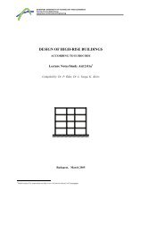
Example 15On the member of Figure 1 NEd= 700 kN;My. Ed= 180 kNm are acting. Check themember <strong>for</strong>a) flexural buckling,b) lateral-torsional buckling,c) combination of flexural and lateral-torsional buckling.Grade of the material: S235Geometry and loads2f y= 23 , 5 kN/cm 1,Ltotε = 0 λ = 93, 19zyM y,EdNEdM y,Edyz NEdLLM y,EdMy,EdLtotN EdL LFigure 1: Geometry and loads.N EdInternal <strong>for</strong>cesThe length of the column isL tot= 10 m , distance of the lateral restrains is L = 5 m .Design <strong>for</strong>ces:NEd= 700 kN;My. Ed= 180 kNmCross-sectional properties:zc fb f= 300mmh wt fyt wzb fywct f= 16h w= 300t w= 8a = 4mmmmmmmmaFigure 2: Cross-sectional properties.13
Cross sectional properties:2A = 120 cm<strong>II</strong><strong>II</strong>43y= cm ; Wy= 1553 cm ; iy= 146,6 mm;Wpl , y=25786 1697 cm43z= cm ; Wz= 480 cm ; iz= 77,5 mm;Wpl , z=7201 725 cmI⋅22( h − tf) 7201⋅( 30 + 2 ⋅1,6−1,6) 6zw===1= ∑34134334( 2 ⋅30⋅1,6+ 30 ⋅ 0,8 ) 87,0 cm3tbiti==Classification of the cross-section <strong>for</strong> compression141797727,5 cmThe cross-section belongs to Class 1 <strong>for</strong> both compression and bending.Checking the resistance of the CROSS-SECTION1. Check <strong>for</strong> compression:N = N = 2820,0 kN > N kN , adequatec,Rd pl , RdEd= 7002. Check <strong>for</strong> bending:Mc,Rd= Mpl , Rd= 398 ,8 kNm > My,Ed= 180 kNm , adequate3. Check <strong>for</strong> the interaction of compression and bending and shear:MN , Rd= 333 kNm > My,Ed= 180 kNm , adequateChecking the flexural buckling resistanceThe buckling lengths:ly= Ltot= 1000 cmlz= L = 500 cmSlenderness and non-dimensional slenderness:λλyzl=il=iyyzz1000= = 68,2214,66500= = 64,547,75λλzyλ=λλ=λFor welded I-section when t f≤ 40 mm :z1y168,22= = 0,72693,964,54= = 0,68793,9- buckling about the y-y axis: b buckling curve,- buckling about the z-z axis: c buckling curve.χ reduction factor <strong>for</strong> the relevant buckling curveχ = 0,769 and χ = 0, 733.y⎧χχ = min⎨y = 0,733⎩χzDesign buckling resistance:z33
A⋅fy 120 ⋅ 23,5Nb, Rd= χz= 0,733⋅= 2065,8 kN > NEd= 700 kN , adequate <strong>for</strong>γM 11,0flexural buckling.Checking the lateral-torsional buckling resistanceDistance between the lateral restrains is l = L = 500 cm .Elastic critical moment:Mcr2 ⎡22⎤π ⋅ E ⋅ I⎢⎛ ⎞z k Iw( k ⋅ l)⋅ G ⋅ It2= C⋅ ++ ( ⋅ − ⋅ ) − ⋅ − ⋅ ⎥( ) ⎢⎜⎟1C2z3(23)22gC zjC zgC zjk ⋅ lπ ⋅ ⋅⎥⎣⎝ kw ⎠ IzE Iz⎦where:l = 500 cmk k = 1, 0 (both ends can have rotation and torsion)= wz g= 0 cm(load is acting in the centroidal axis)z = 0(double symmetric profile)jψ = 1(moments on both ends are equal)kNE = 21000 G = 8077 cmkN2cm2C = 1,0 ; C = 0 ; 01 2C3= 1,22M 1 π ⋅ 21000 ⋅ 7201 ⎡ 1797727,5 500 ⋅8077⋅87⎤cr= ,0 ⋅= 1144, 3 kNm2⎢+⎥500 ⎢⎣7201 π2 ⋅ 21000 ⋅ 7201⎥⎦MMy,Edcr=1801144,3= 0,157>0,04 , the lateral-torsional buckling need to be checked.Non-dimensional slenderness <strong>for</strong> lateral-torsional buckling:Wpl ,yfy 1697 ⋅ 23,5λ LT = == 0,59 > 0,2 , the lateral-torsional buckling need to beMcr114430checked.For welded I-section when h / b f= 33,2 / 30 = 1,107 ≤ 2 the buckling curve c has to beused.χ reduction factor <strong>for</strong> the relevant buckling curve :χLT= 0,791The lateral-torsional resistance:Wpl , yfy 1697 ⋅ 23,5Mb, Rd= χLT= 0 ,791⋅= 315,5 kNm > My,Ed= 180 kNm , adequate.γ1,0MMy,Edb,Rd=180315,5M 1= 0,5715
Interaction of the flexural and lateral-torsional bucklingThe characteristic cross-sectional resistances:NRk= fyA = 23 ,5⋅120= 2820 kNMy, Rk= fyWpl , y= 23,5 ⋅1697= 398, 8 kNmFor cross-sections belongs to Class 1-3. the moments due to shift of the centroidal axis:Δ M y , Ed= 0 kNmTo evaluate the interaction factors the method EC3 detailed in Annex B is applied. For notdirectlyloaded member these factors are as the follows (see Table 3.16 and 3.17).ψ = 1 (moment at both ends are equal)Ck= = 0 ,6 + 0,4ψ= 0,6 + 0,4 = 1,0 >myC mLtyyk yy⎧⎪C⎪= min⎨⎪⎪⎩my( λ y − 0,2)⎛⎜NEd1+⎝χyNRk/ γ⎛⎞⎜NEdC 1+0 8⎟my,⎝ χyNRk/ γM 1 ⎠M 1⎞⎟⎠160,4⎧ ⎛700 ⎞( )⎪1,0⎜1+ 0,726 − 0,2⎟ = 117 ,⎝0,769 ⋅ 2820 / 1,0= min⎠⎨⎪ ⎛700 ⎞1⎜1+ 0,8⎟ = 1,25⎪⎩⎝ 0,769 ⋅ 2820 / 1,0 ⎠k yy= 1, 17If λ ≥ 0, 4:kzyk zyz⎧⎡01 , λ z N⎪⎢1−⎣ ( CmLt− 0,25) χzN= max⎨⎪⎡01 , N⎪⎢1−⎩⎣( CmLt− 0,25) χzNRkRkEdEd/γ/γM 1M 1⎧⎡01 , ⋅ 0,687 700 ⎤⎪⎢1−( )⎥ = 0,969⎣ 10 , − 0,25 0,733⋅2820 / 10 ,= max⎦⎨⎪⎡01 , 700 ⎤=⎪⎢1−⎥ 0,955⎩⎣(1,0 − 0,25) 0,733⋅2820 / 10 , ⎦k zy= 0,969Check the interaction:NEdNχyγNEdNχzγRkM 1RkM 1+ k+ kyyzyMMy,EdχLTy,EdχLT+ ΔMMγy,RkM 1+ ΔMMγy,RkM 1y,Edy,Ed⎤⎥⎦⎤⎥⎦700180=+ 1,17 ⋅2820398,80,769 ⋅0,791⋅1,01,0700180=+ 0,969 ⋅2820398,80,733⋅0,791⋅1,01,0= 0,991 ≤ 1= 0,892 ≤ 1the member is adequate <strong>for</strong> the interaction of flexural and lateral-torsional buckling.
Example 16On the column of Figure 3 distributed loadF Ed= 450 kN are acting. Check the column <strong>for</strong>q Ed= 6 kN/m and compression <strong>for</strong>ced) flexural buckling,e) lateral-torsional buckling,f) combination of flexural and lateral-torsional buckling.Grade of the material: S275Geometry and loads of the column2f y= 27 , 5 kN/cm = 0, 924ε λ = 86, 182yFEdF Ed F Edzyzq EdLq EdLLyyzzF EdFigure 3: Geometry of the column.Internal <strong>for</strong>cesThe length of the column isDesign <strong>for</strong>ces:L = 7 m , lateral restrains are only at the bolt ends.- maximal normal <strong>for</strong>ce and moment, coexist shear <strong>for</strong>ce (at mid-span):N= 450 kN;M.= 36,75 kNm;V =Ed y EdEd0- maximal shear <strong>for</strong>ce, coexist normal <strong>for</strong>ce and moment (at support):V= 21 kN;N = 450 kN;M.=Ed Edy Ed0kNmkN17
yq EdyLF EdN Ed[kN]V Ed[kN]M y,Ed[kNm]4502145021Cross-sectional properties: HEB 200t fzc f36,75Figure 4: Internal <strong>for</strong>ces.b = 200 mm t f= 15 mmh = 200 mm t w= 9 mmr = 18 mmhyt wrycwA = 78 ,1 cm4I y= 5696 cm2A vz= 24 ,83 cm4I z= 2003 cm26I w= 171130 cmzbW y= 569 ,6 cm3W z= 200 ,3 cmi y= 8, 54 cm i z= 5, 07 cm3I t= 59 ,28 cm4W, y643 cmpl=3Wpl , z= , 8305 cm3Figure 5: Cross-sectional properties of HEB 200.Classification of the cross-section <strong>for</strong> compressionFlange:cfctffb tw200 9= − r − = −18− = 77,5 mm2 2 2 277,5= = 5,17 < 9 ⋅ε= 8,3215the flange belongs to Class 1.Web:c = h − 2 ⋅ r − 2 ⋅t= 200 − 2 ⋅18− 2 ⋅15= 134 mmctwww=1349f= 14,89 < 33⋅ε= 30,5the web belongs to Class 1.The cross-section belongs to Class 1 <strong>for</strong> compression.18
Classification of the cross-section <strong>for</strong> bendingFlange:Equal to the classification <strong>for</strong> compression, it belongs to Class 1.Web:ctww= 14 ,89 < 72 ⋅ε= 66,56the web belongs to Class 1.The cross-section belongs to Class 1 <strong>for</strong> bending.Checking the resistance of the CROSS-SECTION1. Check <strong>for</strong> compression:A⋅fy 78,1 ⋅ 27,5Nc,Rd= Npl , Rd= = = 2147 kN > NEd= 500 kNγ 1,0NNEdc,Rd= 0,23M 02. Check <strong>for</strong> bending (at mid-span):The cross-section is adequate <strong>for</strong> compression.Wpl , y⋅ fy 643⋅27,5Mc,Rd= Mpl , Rd= = = 176,7 kNm > My,Ed= 140 kNmγ 1,0MMy,Edc,Rd= 0,79M 0The cross-section is adequate <strong>for</strong> bending.3. Check <strong>for</strong> shear (at support):Local buckling under shear can not per<strong>for</strong>med.Avz⋅ fy 24,83⋅27,5Vc,Rd = Vpl , Rd= == 394,2 kN > VEd= 300 kN⋅ γ 3 ⋅1,0VVEdc,Rd= 0,763M 0The cross-section is adequate <strong>for</strong> shear.4. Check <strong>for</strong> the interaction of compression, bending and shear:VEdFor each cross-section the < 0, 5 , the reduction of the moment resistance due toVc,Rdshear <strong>for</strong>ce is not needed. The cross-section at the mid-span under combined compressionand bending need to be checked, as follows:0,25 ⋅ N0,5 ⋅ hwγpl , Rd⋅ tM 0w= 0,25⋅2147 = 537 kN⋅ fyN0,5 ⋅17⋅ 9 ⋅ 27,5== 210,4 kN1,0>Ed= 450 kN
Nn =NEdpl , Rd=A − 2 ⋅b⋅tfa =A4502147= 0,2178,1 − 2 ⋅ 20 ⋅1,5== 0,23278,1 My,Ed= 36, 75 kNm , adequate.Checking the flexural buckling resistanceThe buckling lengths:ly= lz= L = 700 cmSlenderness and non-dimensional slenderness:lλy=ilλz=iyyzz==7008,547005,07= 81,97= 138,07λyλy= =λ11λzλz= =λ81,9786,82138,0786,82= 0,944= 1,59For hot-rolled I-section when h / ≤ 1, 2 and t f≤ 100 mm :- buckling about the y-y axis: b buckling curve,- buckling about the z-z axis: c buckling curve.χ reduction factor <strong>for</strong> the relevant buckling curveχ = 0,633 and χ = 0, 287 .yzb f⎧χχ = min⎨y = 0,287⎩χzDesign buckling resistance:A⋅fy 78,1 ⋅ 27,5Nb, Rd= χz= 0,287 ⋅ = 616,2 kN > NEd= 450 kN , adequate <strong>for</strong>γM 11,0flexural buckling.Checking the lateral-torsional buckling resistanceDistance between the lateral restrains is l = L = 700 cm .Elastic critical moment:2 ⎡22⎤π ⋅ E ⋅ I⎢⎛ ⎞z k Iw( k ⋅ l)⋅ G ⋅ It2M = ⋅ ++ ( ⋅ − ⋅ ) − ⋅ − ⋅ ⎥( ) ⎢⎜⎟crC1 C2z3(23)22gC zjC zgC zjk ⋅ lπ ⋅ ⋅⎥⎣⎝ kw ⎠ IzE Iz⎦where:k = k w= 1,0 (both ends can have rotation and torsion)z g= h / 2 = + 10 cm (load is acting on the upper flange)20
z = 0(double symmetric profile)jkNE = 21000 G = 8077 cmkN2cm2C = 1,132 ; C = 0, 459 ; 5251 2C3= 0, (see Table)2π ⋅ 21000 ⋅ 2003 ⎡M cr= 1,132 ⋅2⎢700 ⎢⎣= 204, 5 kNm17113020032700 ⋅8077⋅59,28++2π ⋅ 21000 ⋅ 2003( 0,459 ⋅10)2⎤− 0,459 ⋅10⎥=⎥⎦MMy,Edcr36,75= = 0,18204,5>0,04 , the lateral-torsional buckling need to be checked.Non-dimensional slenderness <strong>for</strong> lateral-torsional buckling:Wpl ,yfy 643⋅27,5λ LT = == 0,929 > 0,2 , the lateral-torsional buckling need to beMcr20450checked.For hot-rolled I-section when h / = 20 / 20 = 1,0 ≤ 2 the buckling curve a has to be used.χ reduction factor <strong>for</strong> the relevant buckling curve :χLT= 0,714b fThe lateral-torsional resistance:Wpl , yfy 643⋅27,5Mb, Rd= χLT= 0 ,714 ⋅ = 126,2 kNm > My,Ed= 36, 75 kNm ,γM 11,0adequate.MMy,Edb,Rd36,75= = 0,29126,2Interaction of the flexural and lateral-torsional bucklingThe characteristic cross-sectional resistances:NRk= fyA = 27 ,5⋅78,1 = 2147 kNMy, Rk= fyWpl , y= 27,5⋅643 = 176, 7 kNmFor cross-sections belongs to Class 1-3. the moments due to shift of the centroidal axis:Δ M y , Ed= 0 kNmTo evaluate the interaction factors the method EC3 detailed in Annex B is applied. Fordirectly loaded member these factors are as the follows (see Table 3.16 and 3.17).Mh= 0 kNm;Ms= My, Ed= 36, 75 kNm (moment at both ends and at mid-span)ψ = 1 (moment at both ends are equal to zero)21
Mh 0αh= = = 0 (moment at both ends are equal to zero)M 36,75sC = 0 ,95 + 0,05α = 0,95 > 0,4 (<strong>for</strong> distributed load)kmy= C mLthyyk yy⎧⎪C⎪= min⎨⎪⎪⎩my( λ y − 0,2)⎛⎜NEd1+⎝χyNRk/ γ⎛⎞⎜NEdC 1+0 8⎟my,⎝ χyNRk/ γM 1 ⎠M 1⎧ ⎛450 ⎞( )⎪0,95⎜1+ 0,944 − 0,2⎟ = 1184 ,⎝0,633⋅2147 / 1,0= min⎠⎨⎪ ⎛450 ⎞0,95⎜1+ 0,8⎟ = 1,202⎪⎩⎝ 0,633⋅2147 / 1,0 ⎠k yy= 1, 184If λ = 1 , 59 ≥ 0,4 :z⎞⎟⎠kzy⎧⎡⎪⎢1−= max ⎣⎨⎪⎡⎪⎢1−⎩⎣01 , ⋅ λ( C − 0,25)mLt01 ,( C − 0,25)mLtzχχzzNNNRkNRkEd/ γEd/ γM 1M 1⎤⎥⎦⎤⎥⎦k zy⎧⎡⎪⎢1−= max⎣⎨⎪⎡⎪⎢1−⎩⎣01 , ⋅159,( 0,95 − 0,25)01 ,( 0,95 − 0,25)Check the interaction:NEdNχyγNEdNχzγRkM 1RkM 1+ k+ kyyzyMMy,EdχLTy,EdχLT+ ΔMMγy,RkM 1+ ΔMMγy,RkM 1400 ⎤⎥ = 0,8340,287 ⋅ 2147 / 10 , ⎦400 ⎤⎥ = 0,8960,287 ⋅ 2147 / 10 , ⎦y,Edy,Ed45036,75=+ 1,184 ⋅2147176,70,633⋅0,714 ⋅1,01,045036,75=+ 0,896 ⋅2147176,70,287 ⋅0,714 ⋅1,01,0= 0,676 ≤ 1= 0,991 ≤ 1the member is adequate <strong>for</strong> the interaction of flexural and lateral-torsional buckling.22
3. K jointsJoint typesK joint KT joint N jointT joint X joint Y jointFailure modesIn case of joint between I-section chord andsquare hollow section web members thefailure modes b), c), e) and f) may occurs.The failure modes a) and d) are may notoccurred.a) Chord face failure (plastic failure of thechord face) or chord plastification(plastic failure of the chord crosssection);b) Chord side wall failure (or chord webfailure) <strong>by</strong> yielding, crushing orinstability (crippling or buckling of thechord side wall or chord web) under thecompression brace member;c) Chord shear failure;d) Punching shear failure of a hollowsection chord wall (crack initiationleading to rupture of thebrace members from the chord member);e) Brace failure with reduced effectivewidth (cracking in the welds or in thebrace members);f) Local buckling failure of a brace memberor of a hollow section chord member atthe jointlocation.23
Range of validityType of- Joint parameters (i=1 or 2)Joint d w / t w b i / t i és h i / t icompressiontensionh i / b iClass 1. andX≥ 0,5 but ≤ 2,0d w ≤400 mmClass 1. andhhT or Y Class 2. and i / t i ≤ 35 i / t i ≤ 35b 1,0bGap K or N d w ≤400 mm i / t i ≤ 35 i / t i ≤ 35≥ 0,5 but ≤ 2,0See also Table 4.8.<strong>for</strong> notations.Table 4.5.: Range of validity <strong>for</strong> welded joints between RHS brace members and I or Hsection chord members.Resistance of the K-jointsThe Ni, Eddesign bar <strong>for</strong>ce should be less than the Ni, Rddesign resistance of the joint, asfollows:Type of joint Design resistance (i = 1 or 2)T, Y and X jointsChord web yieldingN 1θ 1ht11b1tfwdb0trw0hN1,Rdfy0twb=sin θ ⋅ γBrace failureN1wM 51, Rd= 2 fy1t1peff/ γM 5K and N jointsb1t 1t2Chord web yieldingNi ,Rdf t=sin θy 0 wBrace failureib⋅ γwM 5h1N 1N 2h 2b2Ni ,Rd= 2 fyitipeff/ γM 5θ 1gParameters of the above equations:vθ 2( 2 − α) b0tf+ ( t wr) t fA = A −2 ;effVEd0+tfwdb0[ + 2r+ 7tf0/f; b + h − t ]wfyyiitrw0hChord shearfy 0AvNi ,Rd=sin θ ⋅ γN0 ,Rdp = min t2 γ 10V: vertical component of one of the braceA⋅ fv 0 y 0pl ,Rd= : shear resistance of the chord.3 ⋅ γm 024=3i M 5( A − A ) f + A f 1 − ( V / V )0vy0vγy 0M 5Edpl ,Rd1⎡ h⎤iα =b2 2 w= min⎢+ 5 ( tf+ r) ; 2ti+ 10( tf+ r) ⎥⎦1+4g/ 3tf ⎣sinθiii= M 5,Table 4.8.: Design resistance of welded joint between RHS brace member and I or H sectionchords.2
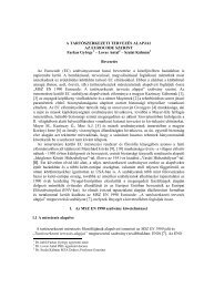
Example 18A lower K-joint of a truss is shown in Figure 1a) Find the resistance of the K-joints if the members has cold <strong>for</strong>med hollow section bracemembers and I section chord members!Geometry of the connectiont 2t1b2h 2h1b1S 2,Ed=130 kNS 1,Ed=130 kNg45°b0tfwdtrw0hS 0,Ed = 216,15 kNS'0,Ed= 400 kNFigure 1: K-joint of hollow section brace and I section chord member.Lower chord: HEAA-120 hot rolled I-sectionb 120 mm0=h 109 mm0=t f= 5,5 mmt w= 4,2 mmr = 12 mmA = 18 , cm062Compression brace member: cold <strong>for</strong>med hollow section 80x80x4b = 180 mmh = 180 mmt = 14 mmTension brace member: cold <strong>for</strong>med hollow section 80x80x4b = 280 mmh = 280 mmt = 24 mmThe gap between the brace members:g = 20 mm25
Range of validityThe range of validity has to be checked to decide whether the design method of EC can beused or not. The range of validity is summarised in Table 4.5Chord member:1. dw= h0 − 2tf− 2r= 109 − 2 ⋅5,5 − 2 ⋅12= 74 < 400 → Ok2. Cross-section class: – the web has to belong at least to Class 2.c = h − 2r− 2t= 109 − 2 ⋅12− 2 ⋅5,5 = 74 mmctwww0f74= = 17,62 < 33⋅ε = 33⋅0,92 = 30,364,2The web belongs to Class 1. → OkCompression brace member:3.b180= = 20,0 ≤ 35t 4→ Ok1h1804. = = 20,0 ≤ 35t 41→Okh1805. = = 1,0 ≥ 0,5 → Okb 801h1806. = = 1,0 ≤ 2,0 → Okb 8017. Cross-section class: – it has to belong at least to Class 2.cctff1= h − 2 ⋅ r − 2 ⋅t=15641= 80 − 2 ⋅8− 2 ⋅ 4 = 56 mm= 14,0 < 33⋅ε = 33⋅0,92 = 30,36The cross-section belongs to Class 1. →Tension brace member:b2808. = = 20,0 ≤ 35 → Okt 42h2809. = = 20,0 ≤ 35t 42→Okh28010. = = 1,0 ≥ 0,5 → Okb 802h28011. = = 1,0 ≤ 2b 802→OkIf all the rules of range of validity are satisfied from the failure modes only the failuremode b (Chord side wall failure or chord web failure), the failure mode c (Chord shearfailure)and the failure mode e (Brace failure) have to be checked, the other failure modescan not be occurred.26Ok
Design resistance of the K-jointChord web failure (failure mode b, see Table 4.8)Ni,Rdwhere:bwfy0twb=sinθ ⋅ γiwM 5⎡ hi⎢ += min sinθ⎢i⎢⎣2ti+ 10⎤5( tf+ r)( t + r) ⎥ ⎥⎥ f ⎦⎡200,64⎤b w= min⎢= 183,0 mm183,0⎥⎣ ⎦fy0twbw27,5 ⋅ 0,42 ⋅18,30Ni,Rd= == 298,92 kNsinθ ⋅ γ sin 45 ⋅1,0iM 5Chord shear failure (failure mode c, see Table 4.8)Assumption #1 <strong>for</strong> brace member <strong>for</strong>ce:Ni,Rdwhere:Av=fy0Av3 sinθi⋅ γM5( 2 − α) ⋅b0tf+ ( tw+ r) ⋅tf= A −202( 2 − 0,232) ⋅12,0 ⋅ 0,55 + ( 0,42 + 2 ⋅1,2) ⋅ 0,55 8,48A v= 18 , 6 −= cmα =11+4g121+4 ⋅ 20 / 3⋅5,5=,2 22/ 3tf= 0 23227,5⋅8,48N i,Rd== 190,41 kN3 sin 45⋅10,Assumption #2 <strong>for</strong> chord member <strong>for</strong>ce:N0,Rdwhere:VEd=( A − A ) f + A f 1−( V / V )0vy0vγy0M 5Edpl ,Rd: brace <strong>for</strong>ce component perpendicular to the axis of the chordVEd = S1 , Edsin 45 = 130 ⋅ sin 45 = 91,92 kNAv⋅ fy08,48 ⋅ 27,5Vpl ,Rd= = = 134,64 kN⋅ γ 3 ⋅1,03M 0( 18,6 − 8,48) ⋅ 27,5 + 8,48 ⋅ 27,5 1−( 9192 , / 134,64)2N0 Rd=,=447,08 kN1,0227
Brace failure (failure mode e, see Table 4.8)Ni ,Rd= 2 fyitipeff/ γM 5= 2 ⋅ 27,5 ⋅ 0,4 ⋅ 6,67 / 1,0 = 146,74kNwhere:eff[ + 2r+ 7tf0/f; b + h − t ]p = min t2w[ 66 , 7;152] = 66,mmp eff= min7Checking the design resistance of the K-jointThe maximal <strong>for</strong>ce acting on the jointNi,Ed= S, Ed130 kN1='N, Ed= S,Ed400 kN0 0=The resistance of the jointfy[ 29892 , kN; 14674 , kN; 190,kN]N i,Rd= min41Checking of the K-jointNyiiii= 146,74 kN > S1 = kN → The brace member is adequate!i,Rd , Ed130'N0 , Rd= 447,08 kN > S0,Ed= 400 kN → The chord member is adequate!28
Afl⋅ Nt,Rd 14,4⋅1192,6FEd , fl= == 443 kNA 38,77Design <strong>for</strong>ce of the web:A2web= A − 2 ⋅ Afl= 38,77 − 2 ⋅14,4 = 9,97 cm area of the webAweb⋅ Nt ,Rd 9,97 ⋅1193,6FEd ,w=== 306,7 kNA 38,77Design resistance of individual fastenersFlangeShear resistance per shear planeThe shear plane passes through the unthreaded portion of the bolt: αv= 0, 6F21,4 ⋅ π0,6 ⋅80⋅αv⋅ fub⋅ Ab= n ⋅= 1⋅4= 59,kN <strong>for</strong> one bolt in a flangeγ1,25flv,Rd11M 2Bearing resistanceFflb,Rdk1⋅ αb⋅ f=γuM 2⋅ d ⋅ tcalculation of k 1 :- perpendicular to the direction of the load transfer, <strong>for</strong> edge bolts⎛ e240 ⎞⎜2,8⋅−17, = 2,8⋅−17, = 5,76⎟k1= min⎜d015 ⎟ → k = 12,5⎜⎟⎝2,5⎠calculation of α b :- in the direction of the load transfer, <strong>for</strong> edge bolts⎛ e140 ⎞⎜ = = 0,88⎟⎜ 3⋅d03⋅15⎟⎜ f⎟ub 80αb= min⎜= = 157 , ⎟→ α b= 0,88⎜ fu51 ⎟⎜1⎟⎜⎟⎝⎠- in the direction of the load transfer, <strong>for</strong> inner bolts (we assume, that at least 3 bolt-row isrequired)30
⎛ p11 40 1 ⎞⎜ − = − = 0,638⎟⎜ 3⋅d04 3⋅154 ⎟⎜ f⎟ub 80αb= min⎜= = 157 ,⎟ → α b= 0,638⎜ fu51⎟⎜1⎟⎜⎟⎝⎠calculation of the bearing resistance- the bearing resistance is the smallestfl k1⋅ αb⋅ fu⋅ d ⋅ t 2,5 ⋅ 0,368 ⋅ 51⋅1,4 ⋅ 0,9Fb,Rd === 81,99 kNγ1,25M 2WebShear resistance per shear planeThe shear plane passes through the unthreaded portion of the bolt: αv= 0, 6F21,4 ⋅ π0,6 ⋅80⋅αv⋅ fub⋅ Ab= n ⋅= 2 ⋅4= 118,kN <strong>for</strong> one bolt in a webγ1,25wv,Rd22M 2k = 1and = 0,638Bearing resistance ( 2,5α bsame than the flange)w k1⋅ αb⋅ fu⋅ d ⋅ t 2,5 ⋅ 0,368 ⋅ 51⋅1,4 ⋅ 0,6Fb,Rd === 54,66 kNγ1,25M 2Required number of boltsFlangenFEd , fl 443= = 7,49 → n flflalk= 2x4F 5911 ,flreq=v,RdWebnFEd ,w 306,7= = 5,6 → n w walk= 1x6F 54,66wreq=b,RdDesign of the coversFlangeflA ≥ A → t ≥ t = mm → t alk= 10mmflnet ,cov erflnetcov er f9WebAww2net ,cov er≥ Anet= Aw− d ⋅tw= 9,cm → t alk= 8mm00731
11M14-8.8HEA-16080-840 40 40 40 40 40 40160-10e =402 2p =801604040 40 40 40 40e =40 p =40 40 40 40400Figure 2: Geometry of the connection.Example 4.7Design the bolted connection of HEB 400 section F Ed= 3615 kN design tension <strong>for</strong>ce! Thecross-section is shown in Figure 3 The grade of the steel is S235, the bolts of the flanges areM30, 5.6, the bolts of the web are M16, 5.6.Grade of the material: S235Bolts: M30, 5.6 (flanges)f y= 23 , 5 kN/cm2f u= 36 , 0 kN/cmd = 30 mm d 33 mm0=M16, 5.6 (web) d = 16 mm d 18 mm0=2f yb= 30 , 0 kN/cm2f ub= 50 , 0 kN/cm2Cross-section of the memberhftyt wyb = 300 mmt f= 24,0 mmh = 400 mmt w= 13,5 mmrzb2A = 198 cmFigure 3: The cross-section of HEB 400.32
Location of the boltsFlange: bolts M30The minimum distances of the bolts from the edges and between the boltse2 min= 1,2 ⋅ d0= 39,6 mm and p2 min= 2,4 ⋅ d0= 79,2 mm . With this distances 2 bolts canbe applied in each flanges Figure 4.The distances in the direction of the <strong>for</strong>ce transfer are e1 = 75 mm and p = 120 1mm , inthe other direction is e = 260 mm .Web: bolts M16The minimum distances of the bolts from the edges and between the boltse2 min= 1,2 ⋅ d0= 21,6 mm and p2 min= 2,4 ⋅ d0= 43,2 mm . With this distances 2 bolts canbe applied in each flanges Figure 4.The distances in the direction of the <strong>for</strong>ce transfer are e1 = 40 mm and p 70 1= mm , in theother direction is e2 = 35 mm and p = 75 2mm . M30-5.6M16-5.6Figure 4: Geometry of the connection.With the above consideration the design resistance of the tension member (two L-sections)can be calculated as the follows.The design <strong>for</strong>ces of the flange and the webThe F Ed= 3615 kN design tension <strong>for</strong>ce has to be distributed to the flange and web in theration of the areas.Design <strong>for</strong>ce of the flange:A fl=2= 2 , 4 ⋅ 30 72 cm area of the flangeAfl⋅ FEd72 ⋅3615FEd , f= = = 1314,5 kNA 198Design <strong>for</strong>ce of the web:A2web= A − 2 ⋅ Afl= 198 − 2 ⋅ 72 = 54 cm area of the webAweb⋅ FEd54 ⋅ 3615FEd ,w= = = 985,9 kNA 19833
The design resistance of the tension memberThe design plastic resistance of the gross cross-section:NA⋅fy 198⋅23,5= =γ 010 ,pl,Rd=4653MThe design ultimate resistance of the net cross-section at holes <strong>for</strong> fasteners:kN( 198 − 4 ⋅ 3,3⋅2,4 − 4 ⋅18, ⋅135, )Anet⋅ fu⋅ 36Nu,Rd= 0,9 ⋅ = 0,9 ⋅= 4059,07 kNγ1,25M 2The resistance of the tension member:N= N= 4059,t,Rd u,Rd07kNDesign resistance of individual boltsShear resistance per shear planeThe shear plane passes through the unthreaded portion of the bolt: αv= 0, 6FF21,6 ⋅ π0,6 ⋅ 50 ⋅αv⋅ fub⋅ Ab= 2 ⋅= 2 ⋅4= 96,kN <strong>for</strong> bolts M16γ1,2516v,Rd5M 223 ⋅ π0,6 ⋅ 50 ⋅αv⋅ fub⋅ Ab= 2 ⋅= 2 ⋅4= 339,kN <strong>for</strong> bolts M30γ1,2530v,Rd3M 2Bearing resistance of bolts M16F16b,Rdk1⋅ αb⋅ f=γuM 2⋅ d ⋅ tcalculation of k 1 :- perpendicular to the direction of the load transfer, <strong>for</strong> edge bolts⎛ e235 ⎞⎜2,8⋅−17, = 2,8⋅−17, = 3,74⎟k1= min⎜d018 ⎟ → k = 12,5⎜⎟⎝2,5⎠- perpendicular to the direction of the load transfer, <strong>for</strong> inner bolts⎛ p275 ⎞⎜1,4 ⋅ −17, = 1,4 ⋅ −17, = 413 , ⎟k1= min⎜d018 ⎟ → k = 12,5⎜⎟⎝2,5⎠calculation of α b :- in the direction of the load transfer, <strong>for</strong> edge bolts34
⎛ e140 ⎞⎜ = = 0,74⎟⎜ 3⋅d03⋅18⎟⎜ f⎟ub 50αb= min⎜= = 138 , ⎟→ α b= 0,74⎜ fu36 ⎟⎜1⎟⎜⎟⎝⎠- in the direction of the load transfer, <strong>for</strong> inner bolts (we assume, that at least 3 bolt-row isrequired)⎛ p11 70 1 ⎞⎜ − = − = 1,05⎟⎜ 3⋅d04 3⋅184 ⎟⎜ f⎟ub 50αb= min⎜= = 138 ,⎟ →⎜ f 36⎟α = 1, b0u⎜1⎟⎜⎟⎝⎠calculation of the bearing resistance- the bearing resistance is the smallest, when: k 2,5 and = 0,74F35k1⋅ αb⋅ fu⋅ d ⋅ t 2,5 ⋅ 0,74 ⋅ 36 ⋅1,6 ⋅135,= == 115,kN <strong>for</strong> bolts M16.γ1,251 =16b,Rd08M 2Bearing resistance of bolts M30F30b,Rdk1⋅ αb⋅ f=γuM 2⋅ d ⋅ tcalculation of k 1 :- perpendicular to the direction of the load transfer, <strong>for</strong> edge bolts⎛ e255 ⎞⎜2,8⋅−17, = 2,8⋅−17, = 2,96⎟k1= min⎜d033 ⎟ → k = 12,5⎜⎟⎝2,5⎠- perpendicular to the direction of the load transfer, <strong>for</strong> inner boltsthe connection does not contains such a bolt.calculation of α b :- in the direction of the load transfer, <strong>for</strong> edge bolts⎛ e175 ⎞⎜ = = 0,76⎟⎜ 3⋅d03⋅33 ⎟⎜ f⎟ub 50αb= min⎜= = 138 , ⎟→ α b= 0,76⎜ fu36 ⎟⎜1⎟⎜⎟⎝⎠- in the direction of the load transfer, <strong>for</strong> inner bolts (we assume, that at least 3 bolt-row isrequired)α b
2A webnet ,cov er= 44 , 6 cm >2A webnet= 44 , 28 cm → Adequate!HEB-400295-1060 180300M30-5.6300-12115-18M16-5.6115-18300-126040 70 70 80 70 70 404407512075 3535 75 7529575 7554012075Figure 5: Geometry of the connection.Example 4.9End-plate type beam-to-beam connection. It is assumed that this is a hinged connection, ittransfers only shear <strong>for</strong>ces, but has no moment resistance. The geometry of the connection isshown in Figure 6: an IPE 300 beam is connected to the welded I-beam using end-plates andM16-5.6 bolts. The reaction <strong>for</strong>ce of the IPE beam is F Ed= 60 kN . Check the resistance ofthe connection!22Grade of the material: S235 f y= 23 , 5 kN/cm f u= 36 , 0 kN/cm βw= 0, 8 αw= 0, 6Bolts: M16, 5.6d = 16 mm d 18 mm0=f yb= 30 , 0 kN/cm2f ub= 50 , 0 kN/cm237
1463240850a = 310 10a = 310,730015030 60 3012035355e = 135e = 230p = 260mmmmmmIPE 300FIÓKTARTÓ7,1Main FŐTARTÓ beamFEd2 db M16 - 5.6 csavar"A" típ. kapcsolatFigure 6: Geometry of the connection.Design resistance of the boltsShear resistance:F21,6 ⋅ π0,6 ⋅ 50 ⋅0,6 ⋅ fub⋅ A= =4= 48,kN ← smallerγ1,25v,Rd25M 2Bearing resistance:k ⋅ fu⋅ d ⋅ tFb,Rd=γM 2calculation of k 1 :- perpendicular to the direction of the load transfer, <strong>for</strong> edge bolts1⋅ αb⎛ e230 ⎞⎜2,8⋅−17, = 2,8⋅−17, = 2,97⎟k1= min⎜d018 ⎟ → k = 12,5⎜⎟⎝2,5⎠- perpendicular to the direction of the load transfer, <strong>for</strong> inner boltsno such bolts.calculation of α b :- in the direction of the load transfer, <strong>for</strong> edge bolts⎛ e135 ⎞⎜ = = 0,648⎟⎜ 3⋅d03⋅33 ⎟⎜ f⎟ub 50αb= min⎜= = 138 , ⎟→ α b= 0,648⎜ fu36⎟⎜1⎟⎜⎟⎝⎠- in the direction of the load transfer, <strong>for</strong> inner bolts:38
no such bolts.calculation of the bearing resistance2,5 ⋅ 0,65 ⋅ 36 ⋅1,6 ⋅1,0F b,Rd== 74,65 kN1,25Design resistance of the weldsWelds on the upper edge of the end plate is neglected, the resistance of the weldsbesides the web is evaluated. Only τ<strong>II</strong>occurs in these welds.A w= 2 ⋅ a ⋅ 7,0 = 2 ⋅ 0,3 ⋅ 7,0 = 4,2 cmfu 4,2 ⋅36FA,Rd, = Fw,Rd= Aw⋅=87,29 kN2⋅β⋅ γ 3 ⋅ 0,8⋅1,25=3w M 2Design resistance of the IPE beamHear resistance of the web besides the welds.fy23,5FA,Rd, = Vc,Rd= Av⋅ = 0,71⋅7,0 ⋅ 67,43 kN3⋅ γ3 ⋅10,=3M 02Design resistance of the end-plateThe effect of the upper flange is neglected, it is assumed that the end-plate is connectedonly to the web.End-plate in shear23,5FA, Rd ,4= 2 ⋅Vc,Rd , h= 2 ⋅= 103 ⋅1,0( 7,0 −1,8) ⋅1,0⋅ 141, kNF/2 F/2Figure 7: Shear area.End-plate in bendingeF/2Figure 7: Bending area.It is assumed that the plate beling the class 3.6,0 0,71e = − = 2, 645 cm2 227,0W = Wel = 1,0⋅ = 8,17cm6fy23,5FA,Rd, 5= 2 ⋅Wel⋅ = 2 ⋅817, ⋅ = 145,17kNe ⋅ γ2,645⋅1,0M 0339
Bolt group failure (shear and fracture)A ny2A hAny1Figure 8: Shear and tension areas.A2( 3,5− 0,9) ⋅1,02, cmny , 1Any,2== 6= shear area2( 6,0−1,8) ⋅1,04,2 cmA h= = tension areaFA,Rd, 6= Veff,Rd=f⋅ Au hy+γM 2 3 ⋅ γM 0⋅ A36 ⋅ 4,2 23,5= + ⋅ 2 ⋅ 2,6 = 19151 , kN1,25 3 ⋅10,fny=It is to be noted, that the above resistance evaluatonsof the end-plate has great importance when theconnection is made <strong>by</strong> and end-plate, which does notreach the upper flange.Figure 9: Alternative connection.Design resistance of the entire connectionFrom the above evaluated resistances the smaller one gives the resistance of the entireconnections.FA Rd= FARd67, 43 kN, , ,min=The connection is adequate, sinceFEd = 60 kN < FA, Rd= 67, 43 kNThe main beam side of the connection is also adequate, since all part of it has equal or higherresistance so has the IPE beam side.40
5. Design of bolted connections subjected to bending and shearExample 4.8Design the bolted connection of a welded I-section beam <strong>for</strong> bending and shear <strong>for</strong>ces. Thecross-section is shown in Figure 1! The shear <strong>for</strong>ce acting on the connection is V Ed= 256 kN .The connection should be full strength.Grade of the material: S355 f y= 35 , 5 kN/cm22f u= 51 , 0 kN/cm ε = 0, 81Bolts: 8.8f yb= 64 , 0 kN/cm2f ub= 80 , 0 kN/cm2Cross-section of the member30014 8001484Classification of the cross-sectionFlange:Web:cctwwcfctwffFigure 1.: The cross-section of the welded beam.bf tw300 8= − 2 ⋅ a − = − 2 ⋅ 4 − = 140,3 mm2 2 2 2the flange belongs to Class 3.140,3= = 10,02 > 10 ⋅ε= 10 ⋅ 0,81 = 8,114= hw− 2 ⋅ 2 ⋅ a = 800 − 2 ⋅ 2 ⋅ 4 = 788,7 mm788,7the web belongs to Class 3.= = 98,58 > 83⋅ε = 83⋅0,81 = 678The cross section belongs to Class 3.Design bending resistance of the cross-section0,8 ⋅801232I y , el= + 2 ⋅30⋅1,4⋅ 40,7 = 173278I 173278W,4185 cmy,ely el= = =zmax41,43cm4185⋅35,5b ,= = 148584 kNcm = 1486 kNm1,0M Rd441
Connection of the flangesThe connection of the flanges has to be designed <strong>for</strong> their tension resistance. The connectionwill be design with inner and outer cover plates and bolts with two shear planes. For thet f= 14,0 mm the bolt M20 is applicable ( d = 20 mm , d0= 22 mm ).Basic rule <strong>for</strong> the bolt geometry: Apply the most possible number of bolts in one crosssection!The with of the inner cover plate can be max. 140 mm (due to the welds). This widthis enough <strong>for</strong> 2-2 bolts in one cross-section on both sides on the web. For the calculation weassume, that 2 bolt rows are require (having 4 bolt in each row). The assumed bolt geometryis shown in Figure 2.8 14 830035 70 35 35 35140 14045 70 45 45 70 4535 70 90 70 35e = 145mmp = 170 mme = 235 mmp = 270mmFigure 2.: Bolt geometry of the flange.Design tension resistance of one flangeDesign plastic resistance of the gross cross-section.NA⋅fy 30 ⋅1,4 ⋅35,5==γ 010 ,pl,Rd=1491MDesign ultimate resistance of the net cross-section at holes <strong>for</strong> fasteners.kN( 30 − 4 ⋅ 2,2)Anet⋅ fu⋅1,4 ⋅ 51Nu,Rd= 0,9 ⋅ = 0,9 ⋅= 1089, 85 kNγ1,25M 2Nt, Rd= Nu,Rd= 1089, 85 kNDesign resistance of individual boltsShear resistance2d ⋅ π⋅ fub,F n4314 ⋅80v,Rd= ⋅ αv⋅ = 2 ⋅ 0,6 ⋅ = 241,15 kNγ1,25M 2Bearing resistancecalculation of k 1 :- perpendicular to the direction of the load transfer, <strong>for</strong> edge bolts⎛ e235 ⎞⎜2,8⋅−17, = 2,8⋅−17, = 2,75⎟k1= min⎜d022 ⎟ → k = 12,5⎜⎟⎝2,5⎠42
- perpendicular to the direction of the load transfer, <strong>for</strong> inner boltsthe connection does not contains such a boltcalculation of α b :- in the direction of the load transfer, <strong>for</strong> edge boltsαb⎛ e145 ⎞⎜ = = 0,68⎟⎜ 3⋅d03⋅22 ⎟⎜ f⎟ub 80= min⎜= = 1,57 ⎟⎜ fu51 ⎟⎜1⎟⎜⎟⎝⎠→ α b= 0,68- in the direction of the load transfer, <strong>for</strong> inner boltsthe connection does not contains such a boltcalculation of the bearing resistanceFk=⋅ α⋅ f⋅ d ⋅ t 2,5 ⋅ 0,68 ⋅ 51⋅2,0 ⋅1,4== 194,1,251 b ub,Rd8γM 2kNShear <strong>for</strong>ce acting on one boltNt,Rd 1089 , 85FEd = = = 136 , 23 kN < Fb,Rdm 8= 194 , 8 kN → The assumed boltgeometry of theflange is adequate.Design of cover plates2Outer: 300 - 8 = ( 30 − 4 ⋅ 2,2) ⋅ 0,8 16, cmA n k=,962Inner: 2x140 - 8 = 2 ⋅ ( 14 − 2 ⋅ 2,2) ⋅ 0,8 15, cm∑AA n b=,362( 30 − 4 ⋅ 2,2) ⋅1,429,2n , hev= ,96 + 15,36 = 32,32 cm > An,lem== 6816 cmThe assumed cover plates of the flanges are adequate.Connection of the webForces action on the connection of the web:We can assume that the shear <strong>for</strong>ce is acting only on the web together with a certainproportion of the bending moment. The bending moment acting on the web can bedetermined <strong>by</strong> the ratio of the inertia of the full cross-section and the web.V Ed= 256 kNIy,ger 34133MG, b,Rd= Mb,Rd⋅ = 1486 ⋅ = 292, 7 kNmI 173278y43
Bolt geometry of the web:Two bolt columns are applicable, the most number of bolts in each column should beapplied, as shown in Figure 3. Cover plates should be used on the both side of the web.2For the web thickness the bolts M16 can be used (area of one bolt A = 2,01 cm ), theassumed bolt number is m = 22 db .4010*70=7004010 10780e = 140p = 170e = 240p = 270mmmmmmmm40 70 40 40 70 40300Figure 3.: Bolt geometry of the web.Forces acting on the bolts:The shear <strong>for</strong>ce can be uni<strong>for</strong>mly distributed between the bolt.VEd256Fv V, ,Ed = = = 11,64 kNm 22From the bending moment the outermost bolts have the largest <strong>for</strong>ce, if we assume elastic<strong>for</strong>ce distribution.Fv,M , EdAssuming that:rmax= MG,b,Rd⋅2r∑r ≅ zizmax35Fv , M , Ed= MG,b,Rd⋅ = 29270 ⋅= 95, 03 kN22z 4 ⋅∑i2 2 2 2( 7 + 14 + 21 + 28 + 35 )The <strong>for</strong>ces from shear and bending acting on the outermost bolt (see Figure 4):2Fv , Ed= Fv, V , Ed+ Fv, M , Ed= 95, 74 kN244
F v,M,EdF v,V,EdF v,EdDesign resistance of individual boltsShear resistanceFigure 4.: Forces on the outermost bolt.fub⋅ A 80 ⋅ 2,01Fv , Rd= 0,6 ⋅ n ⋅ = 2 ⋅ 0,6 ⋅ = 154, 4 kNγ1,25M 2Bearing resistanceThe outermost bolt is edge bolt in both directionscalculation of k 1 :⎛ e240 ⎞⎜2,8⋅−17, = 2,8⋅−17, = 4,5⎟k1= min⎜d018 ⎟ → k = 12,5⎜⎟⎝2,5⎠calculation of α b :⎛ e140 ⎞⎜ = = 0,74⎟⎜ 3⋅d03⋅18⎟⎜ f⎟ub 80αb= min⎜= = 157 , ⎟ → α b= 0,74⎜ fu51 ⎟⎜1⎟⎜⎟⎝⎠calculation of the bearing resistancek1⋅ αb⋅ fu⋅ d ⋅ t 2,5 ⋅ 0,74 ⋅ 51⋅1,6 ⋅ 0,8Fb,Rd === 96,61 kNγ1,25M 2CheckingFv ,Ed= 95 , 74 kN < Fb,Rd= 96,61 kN→The assumed bolt geometry of the web isadequate.Design of cover platesLet apply t = mm cover plates on both sides of the webIcov . w62 ⋅ 0,6 ⋅ 7812344hev= = 47455 cm > Iy,ger= 34133 cm → Adequate.45
Tables ofCold <strong>for</strong>med square hollow sectionsHot <strong>for</strong>med square hollow sectionsHot <strong>for</strong>med rectangular hollow sectionsHE - sectionsIPE - sections
COLD FORMED SQUARE HOLLOE SECTIONbXb Y YsX
Square Hollow Sectionshttp://www.roymech.co.uk/Useful_Tables/Sections/SHS_hf.html2 / 3 2008.02.14. 11:45Square Hollow Section- Hot Formed -BS EN 10210-2:1997Size Thick'sCorner RadiiSecondArea ofRadius of Section Plastic Torsional Constants SectionMass/mMomentSurfaceSectionGyration Modulus ModulusExt'l Int'l of AreaInertia Modulus AreaB T ro ri M/m A I r Z S J C Asmm xmmmm mm mm kg/m cm 2 cm 4 cm cm 3 cm 3 cm 4 cm 3 m 2 /m20 2 3 2 1.1 1.4 0.739 0.727 0.739 0.93 1.22 1.07 0.074820 2.5 3.75 2.5 1.32 1.68 0.835 0.705 0.835 1.08 1.41 1.2 0.073625 2 3 2 1.41 1.8 1.56 0.932 1.25 1.53 2.52 1.81 0.094825 2.5 3.75 2.5 1.71 2.18 1.81 0.909 1.44 1.82 2.97 2.08 0.093625 3 4.5 3 2 2.54 2 0.886 1.6 2.06 3.35 2.3 0.092330 2 3 2 1.72 2.2 2.84 1.14 1.89 2.29 4.53 2.75 0.11530 2.5 3.75 2.5 2.11 2.68 3.33 1.11 2.22 2.74 5.4 3.22 0.11430 3 4.5 3 2.47 3.14 3.74 1.09 2.5 3.14 6.16 3.6 0.11240 2.5 3.75 2.5 2.89 3.68 8.54 1.52 4.27 5.14 13.6 6.22 0.15440 3 4.5 3 3.41 4.34 9.78 1.5 4.89 5.97 15.7 7.1 0.15240 3.2 4.8 3.2 3.61 4.6 10.2 1.49 5.11 6.28 16.5 7.42 0.15240 3.6 5.4 3.6 4.01 5.1 11.1 1.47 5.54 6.88 18.1 8.01 0.15140 4 6 4 4.39 5.59 11.8 1.45 5.91 7.44 19.5 8.54 0.1540 5 7.5 5 5.28 6.73 13.4 1.41 6.68 8.66 22.5 9.6 0.14750 2.5 3.75 2.5 3.68 4.68 17.5 1.93 6.99 8.29 27.5 10.2 0.19450 3 4.5 3 4.35 5.54 20.2 1.91 8.08 9.7 32.1 11.8 0.19250 3.2 4.8 3.2 4.62 5.88 21.2 1.9 8.49 10.2 33.8 12.4 0.19250 3.6 5.4 3.6 5.14 6.54 23.2 1.88 9.27 11.3 37.2 13.5 0.19150 4 6 4 5.64 7.19 25 1.86 9.99 12.3 40.4 14.5 0.1950 5 7.5 5 6.85 8.73 28.9 1.82 11.6 14.5 47.6 16.7 0.18750 6 9 6 7.99 10.2 32 1.77 12.8 16.5 53.6 18.4 0.18550 6.3 9.45 6.3 8.31 10.6 32.8 1.76 13.1 17 55.2 18.8 0.18460 2.5 3.75 2.5 4.46 5.68 31.1 2.34 10.4 12.2 48.5 15.2 0.23460 3 4.5 3 5.29 6.74 36.2 2.32 12.1 14.3 56.9 17.7 0.23260 3.2 4.8 3.2 5.62 7.16 38.2 2.31 12.7 15.2 60.2 18.6 0.23260 3.6 5.4 3.6 6.27 7.98 41.9 2.29 14 16.8 66.5 20.4 0.23160 4 6 4 6.9 8.79 45.4 2.27 15.1 18.3 72.5 22 0.2360 5 7.5 5 8.42 10.7 53.3 2.23 17.8 21.9 86.4 25.7 0.22760 6 9 6 9.87 12.6 59.9 2.18 20 25.1 98.6 28.8 0.22560 6.3 9.45 6.3 10.3 13.1 61.6 2.17 20.5 26 102 29.6 0.22460 8 12 8 12.5 16 69.7 2.09 23.2 30.4 118 33.4 0.21970 3 4.5 3 6.24 7.94 59 2.73 16.9 19.9 92.2 24.8 0.27270 3.2 4.8 3.2 6.63 8.44 62.3 2.72 17.8 21 97.6 26.1 0.27270 3.6 5.4 3.6 7.4 9.42 68.6 2.7 19.6 23.3 108 28.7 0.27170 4 6 4 8.15 10.4 74.7 2.68 21.3 25.5 118 31.2 0.2770 5 7.5 5 9.99 12.7 88.5 2.64 25.3 30.8 142 36.8 0.26770 6 9 6 11.8 15 101 2.59 28.7 35.5 163 41.6 0.26570 6.3 9.45 6.3 12.3 15.6 104 2.58 29.7 36.9 169 42.9 0.26470 8 12 8 15 19.2 120 2.5 34.2 43.8 200 49.2 0.25980 3 4.5 3 7.18 9.14 89.8 3.13 22.5 26.3 140 33 0.31280 3.2 4.8 3.2 7.63 9.72 95 3.13 23.7 27.9 148 34.9 0.31280 3.6 5.4 3.6 8.53 10.9 105 3.11 26.2 31 164 38.5 0.31180 4 6 4 9.41 12 114 3.09 28.6 34 180 41.9 0.3180 5 7.5 5 11.6 14.7 137 3.05 34.2 41.1 217 49.8 0.30780 6 9 6 13.6 17.4 156 3 39.1 47.8 252 56.8 0.30580 6.3 9.45 6.3 14.2 18.1 162 2.99 40.5 49.7 262 58.7 0.30480 8 12 8 17.5 22.4 189 2.91 47.3 59.5 312 68.3 0.29990 3.6 5.4 3.6 9.66 12.3 152 3.52 33.8 39.7 237 49.7 0.35190 4 6 4 10.7 13.6 166 3.5 37 43.6 260 54.2 0.3590 5 7.5 5 13.1 16.7 200 3.45 44.4 53 316 64.8 0.34790 6 9 6 15.5 19.8 230 3.41 51.1 61.8 367 74.3 0.34590 6.3 9.45 6.3 16.2 20.7 238 3.4 53 64.3 382 77 0.34490 8 12 8 20.1 25.6 281 3.32 62.6 77.6 459 90.5 0.339100 3.6 5.4 3.6 10.8 13.7 212 3.92 42.3 49.5 328 62.3 0.391100 4 6 4 11.9 15.2 232 3.91 46.4 54.4 361 68.2 0.39
Rectangular Hollow Sections- Hot Formedhttp://www.roymech.co.uk/Useful_Tables/Sections/RHS_hf.html1 / 4 2008.02.14. 11:44Home<strong>Steel</strong> Section IndexDisclaimer: The in<strong>for</strong>mation on this page has not been checked <strong>by</strong> an independent person. Use this in<strong>for</strong>mation at yourown risk.ROYMECHCNC Plasma Cutting SystemUse your PC to design and cut metal shapes. Free catalog download. www.torchmate.comRectangular Hollow Section-Hot Formed-BS EN 10210-2:1997Ads <strong>by</strong> GoogleTable of Dimensions + PropertiesSizeThick'sCornerRadiusExt'lInt'lMass/mArea ofSectionSecondMoment OfAreaAxisx-xAxisy-yRadius OfGyrationAxisx-xAxisy-ySectionModulusAxisx-xAxisy-yPlasticModulusAxisx-xAxisy-yTorsionalConstantsInertia ModulusSectionSurfaceAreaH B T ro ri M A Ix Iy rx ry Zx Zy Sx Sy J C Asmm mm mm mm mm kg/m cm 2 cm 4 cm 4 cm cm cm 3 cm 3 cm 3 cm 3 cm 4 cm 3 m 2 /m50 25 2.5 3.75 2.5 2.69 3.43 10.4 3.39 1.74 0.994 4.16 2.71 5.33 3.22 8.42 4.61 0.14450 25 3 4.5 3 3.17 4.04 11.9 3.83 1.72 0.973 4.76 3.06 6.18 3.71 9.64 5.2 0.14250 30 2.5 3.75 2.5 2.89 3.68 11.8 5.22 1.79 1.19 4.73 3.48 5.92 4.11 11.7 5.73 0.15450 30 3 4.5 3 3.41 4.34 13.6 5.94 1.77 1.17 5.43 3.96 6.88 4.76 13.5 6.51 0.15250 30 3.2 4.8 3.2 3.61 4.6 14.2 6.2 1.76 1.16 5.68 4.13 7.25 5 14.2 6.8 0.15250 30 3.6 5.4 3.6 4.01 5.1 15.4 6.67 1.74 1.14 6.16 4.45 7.94 5.46 15.4 7.31 0.15150 30 4 6 4 4.39 5.59 16.5 7.08 1.72 1.13 6.6 4.72 8.59 5.88 16.6 7.77 0.1550 30 5 7.5 5 5.28 6.73 18.7 7.89 1.67 1.08 7.49 5.26 10 6.8 19 8.67 0.14760 40 2.5 3.75 2.5 3.68 4.68 22.8 12.1 2.21 1.6 7.61 6.03 9.32 7.02 25.1 9.73 0.19460 40 3 4.5 3 4.35 5.54 26.5 13.9 2.18 1.58 8.82 6.95 10.9 8.19 29.2 11.2 0.19260 40 3.2 4.8 3.2 4.62 5.88 27.8 14.6 2.18 1.57 9.27 7.29 11.5 8.64 30.8 11.7 0.19260 40 3.6 5.4 3.6 5.14 6.54 30.4 15.9 2.16 1.56 10.1 7.93 12.7 9.5 33.8 12.8 0.19160 40 4 6 4 5.64 7.19 32.8 17 2.14 1.54 10.9 8.52 13.8 10.3 36.7 13.7 0.1960 40 5 7.5 5 6.85 8.73 38.1 19.5 2.09 1.5 12.7 9.77 16.4 12.2 43 15.7 0.18760 40 6 9 6 7.99 10.2 42.3 21.4 2.04 1.45 14.1 10.7 18.6 13.7 48.2 17.3 0.18560 40 6.3 9.45 6.3 8.31 10.6 43.4 21.9 2.02 1.44 14.5 11 19.2 14.2 49.5 17.6 0.18480 40 3 4.5 3 5.29 6.74 54.2 18 2.84 1.63 13.6 9 17.1 10.4 43.8 15.3 0.23280 40 3.2 4.8 3.2 5.62 7.16 57.2 18.9 2.83 1.63 14.3 9.46 18 11 46.2 16.1 0.23280 40 3.6 5.4 3.6 6.27 7.98 62.8 20.6 2.81 1.61 15.7 10.3 20 12.1 50.8 17.5 0.23180 40 4 6 4 6.9 8.79 68.2 22.2 2.79 1.59 17.1 11.1 21.8 13.2 55.2 18.9 0.2380 40 5 7.5 5 8.42 10.7 80.3 25.7 2.74 1.55 20.1 12.9 26.1 15.7 65.1 21.9 0.22780 40 6 9 6 9.87 12.6 90.5 28.5 2.68 1.5 22.6 14.2 30 17.8 73.4 24.2 0.22580 40 6.3 9.45 6.3 10.3 13.1 93.3 29.2 2.67 1.49 23.3 14.6 31.1 18.4 75.6 24.8 0.22480 40 8 12 8 12.5 16 106 32.1 2.58 1.42 26.5 16.1 36.5 21.2 85.8 27.4 0.21976.2 50.8 3 4.5 3 5.62 7.16 56.7 30 2.81 2.05 14.9 11.8 18.2 13.7 62.1 19.1 0.24676.2 50.8 3.2 4.8 3.2 5.97 7.61 59.8 31.6 2.8 2.04 15.7 12.4 19.2 14.5 65.7 20.1 0.24676.2 50.8 3.6 5.4 3.6 6.66 8.49 65.8 34.6 2.78 2.02 17.3 13.6 21.3 16 72.5 22 0.24576.2 50.8 4 6 4 7.34 9.35 71.5 37.5 2.77 2 18.8 14.8 23.3 17.5 79.1 23.8 0.244
Rectangular Hollow Sections- Hot Formedhttp://www.roymech.co.uk/Useful_Tables/Sections/RHS_hf.html2 / 4 2008.02.14. 11:4476.2 50.8 5 7.5 5 8.97 11.4 84.4 43.9 2.72 1.96 22.2 17.3 28 20.9 94.2 27.8 0.24176.2 50.8 6 9 6 10.5 13.4 95.6 49.2 2.67 1.91 25.1 19.4 32.2 23.9 108 31.2 0.23976.2 50.8 6.3 9.45 6.3 11 14 98.6 50.6 2.66 1.9 25.9 19.9 33.4 24.8 111 32 0.23876.2 50.8 8 12 8 13.4 17.1 113 57 2.57 1.83 29.6 22.4 39.4 29 129 36.1 0.23390 50 3 4.5 3 6.24 7.94 84.4 33.5 3.26 2.05 18.8 13.4 23.2 15.3 76.5 22.4 0.27290 50 3.2 4.8 3.2 6.63 8.44 89.1 35.3 3.25 2.04 19.8 14.1 24.6 16.2 80.9 23.6 0.27290 50 3.6 5.4 3.6 7.4 9.42 98.3 38.7 3.23 2.03 21.8 15.5 27.2 18 89.4 25.9 0.27190 50 4 6 4 8.15 10.4 107 41.9 3.21 2.01 23.8 16.8 29.8 19.6 97.5 28 0.2790 50 5 7.5 5 9.99 12.7 127 49.2 3.16 1.97 28.3 19.7 36 23.5 116 32.9 0.26790 50 6 9 6 11.8 15 145 55.4 3.11 1.92 32.2 22.1 41.6 27 133 37 0.26590 50 6.3 9.45 6.3 12.3 15.6 150 57 3.1 1.91 33.3 22.8 43.2 28 138 38.1 0.26490 50 8 12 8 15 19.2 174 64.6 3.01 1.84 38.6 25.8 51.4 32.9 160 43.2 0.259100 50 3 4.5 3 6.71 8.54 110 36.8 3.58 2.08 21.9 14.7 27.3 16.8 88.4 25 0.292100 50 3.2 4.8 3.2 7.13 9.08 116 38.8 3.57 2.07 23.2 15.5 28.9 17.7 93.4 26.4 0.292100 50 3.6 5.4 3.6 7.96 10.1 128 42.6 3.55 2.05 25.6 17 32.1 19.6 103 29 0.291100 50 4 6 4 8.78 11.2 140 46.2 3.53 2.03 27.9 18.5 35.2 21.5 113 31.4 0.29100 50 5 7.5 5 10.8 13.7 167 54.3 3.48 1.99 33.3 21.7 42.6 25.8 135 36.9 0.287100 50 6 9 6 12.7 16.2 190 61.2 3.43 1.95 38.1 24.5 49.4 29.7 154 41.6 0.285100 50 6.3 9.45 6.3 13.3 16.9 197 63 3.42 1.93 39.4 25.2 51.3 30.8 160 42.9 0.284100 50 8 12 8 16.3 20.8 230 71.7 3.33 1.86 46 28.7 61.4 36.3 186 48.9 0.279100 60 3 4.5 3 7.18 9.14 124 55.7 3.68 2.47 24.7 18.6 30.2 21.2 121 30.7 0.312100 60 3.2 4.8 3.2 7.63 9.72 131 58.8 3.67 2.46 26.2 19.6 32 22.4 129 32.4 0.312100 60 3.6 5.4 3.6 8.53 10.9 145 64.8 3.65 2.44 28.9 21.6 35.6 24.9 142 35.6 0.311100 60 4 6 4 9.41 12 158 70.5 3.63 2.43 31.6 23.5 39.1 27.3 156 38.7 0.31100 60 5 7.5 5 11.6 14.7 189 83.6 3.58 2.38 37.8 27.9 47.4 32.9 188 45.9 0.307100 60 6 9 6 13.6 17.4 217 95 3.53 2.34 43.4 31.7 55.1 38.1 216 52.1 0.305100 60 6.3 9.45 6.3 14.2 18.1 225 98.1 3.52 2.33 45 32.7 57.3 39.5 224 53.8 0.304100 60 8 12 8 17.5 22.4 264 113 3.44 2.25 52.8 37.8 68.7 47.1 265 62.2 0.299120 60 3.6 5.4 3.6 9.66 12.3 227 76.3 4.3 2.49 37.9 25.4 47.2 28.9 183 43.3 0.351120 60 4 6 4 10.7 13.6 249 83.1 4.28 2.47 41.5 27.7 51.9 31.7 201 47.1 0.35120 60 5 7.5 5 13.1 16.7 299 98.8 4.23 2.43 49.9 32.9 63.1 38.4 242 56 0.347120 60 6 9 6 15.5 19.8 345 113 4.18 2.39 57.5 37.5 73.6 44.5 279 63.8 0.345120 60 6.3 9.45 6.3 16.2 20.7 358 116 4.16 2.37 59.7 38.8 76.7 46.3 290 65.9 0.344120 60 8 12 8 20.1 25.6 425 135 4.08 2.3 70.8 45 92.7 55.4 344 76.6 0.339120 60 10 12 8 24.6 31.3 503 155 4.01 2.23 83.8 51.7 112 65.6 397 86.8 0.339120 80 3.6 5.4 3.6 10.8 13.7 276 147 4.48 3.27 46 36.7 55.6 42 301 59.5 0.391120 80 4 6 4 11.9 15.2 303 161 4.46 3.25 50.4 40.2 61.2 46.1 330 65 0.39120 80 5 7.5 5 14.7 18.7 365 193 4.42 3.21 60.9 48.2 74.6 56.1 401 77.9 0.387120 80 6 9 6 17.4 22.2 423 222 4.37 3.17 70.6 55.6 87.3 65.5 468 89.6 0.385120 80 6.3 9.45 6.3 18.2 23.2 440 230 4.36 3.15 73.3 57.6 91 68.2 487 92.9 0.384120 80 8 12 8 22.6 28.8 525 273 4.27 3.08 87.5 68.1 111 82.6 587 110 0.379120 80 10 15 10 27.4 34.9 609 313 4.18 2.99 102 78.1 131 97.3 688 126 0.374140 80 4 6 4 13.2 16.8 441 184 5.12 3.31 62.9 46 77.1 52.2 411 76.5 0.43140 80 5 7.5 5 16.3 20.7 534 221 5.08 3.27 76.3 55.3 94.3 63.6 499 91.9 0.427140 80 6 9 6 19.3 24.6 621 255 5.03 3.22 88.7 63.8 111 74.4 583 106 0.425140 80 6.3 9.45 6.3 20.2 25.7 646 265 5.01 3.21 92.3 66.2 115 77.5 607 110 0.424140 80 8 12 8 25.1 32 776 314 4.93 3.14 111 78.5 141 94.1 733 130 0.419140 80 10 15 10 30.6 38.9 908 362 4.83 3.05 130 90.5 168 111 862 150 0.414150 100 4 6 4 15.1 19.2 607 324 5.63 4.11 81 64.8 97.4 73.6 660 105 0.49150 100 5 7.5 5 18.6 23.7 739 392 5.58 4.07 98.5 78.5 119 90.1 807 127 0.487150 100 6 9 6 22.1 28.2 862 456 5.53 4.02 115 91.2 141 106 946 147 0.485150 100 6.3 9.45 6.3 23.1 29.5 898 474 5.52 4.01 120 94.8 147 110 986 153 0.484150 100 8 12 8 28.9 36.8 1087 569 5.44 3.94 145 114 180 135 1203 183 0.479150 100 10 15 10 35.3 44.9 1282 665 5.34 3.85 171 133 216 161 1432 214 0.474150 100 12 18 12 41.4 52.7 1450 745 5.25 3.76 193 149 249 185 1633 240 0.469150 100 12.5 18.75 12.5 42.8 54.6 1488 763 5.22 3.74 198 153 256 190 1679 246 0.468160 80 4 6 4 14.4 18.4 612 207 5.77 3.35 76.5 51.7 94.7 58.3 493 88.1 0.47160 80 5 7.5 5 17.8 22.7 744 249 5.72 3.31 93 62.3 116 71.1 600 106 0.467160 80 6 9 6 21.2 27 868 288 5.67 3.27 108 72 136 83.3 701 122 0.465160 80 6.3 9.45 6.3 22.2 28.2 903 299 5.66 3.26 113 74.8 142 86.8 730 127 0.464
Rectangular Hollow Sections- Hot Formedhttp://www.roymech.co.uk/Useful_Tables/Sections/RHS_hf.html3 / 4 2008.02.14. 11:44160 80 8 12 8 27.6 35.2 1091 356 5.57 3.18 136 89 175 106 883 151 0.459160 80 10 15 10 33.7 42.9 1284 411 5.47 3.1 161 103 209 125 1041 175 0.454160 80 12 18 12 39.5 50.3 1449 455 5.37 3.01 181 114 240 142 1175 194 0.449160 80 12.5 18.75 12.5 40.9 52.1 1485 465 5.34 2.99 186 116 247 146 1204 198 0.448180 100 4 6 4 16.9 21.6 945 379 6.61 4.19 105 75.9 128 85.2 852 127 0.55180 100 5 7.5 5 21 26.7 1153 460 6.57 4.15 128 92 157 104 1042 154 0.547180 100 6 9 6 24.9 31.8 1350 536 6.52 4.11 150 107 186 123 1224 179 0.545180 100 6.3 9.45 6.3 26.1 33.3 1407 557 6.5 4.09 156 111 194 128 1277 186 0.544180 100 8 12 8 32.6 41.6 1713 671 6.42 4.02 190 134 239 157 1560 224 0.539180 100 10 15 10 40 50.9 2036 787 6.32 3.93 226 157 288 188 1862 263 0.534180 100 12 18 12 47 59.9 2320 886 6.22 3.85 258 177 333 216 2130 296 0.529180 100 12.5 18.75 12.5 48.7 62.1 2385 908 6.2 3.82 265 182 344 223 2191 303 0.528200 100 4 7.5 5 18.1 23.1 1213 414 7.25 4.23 121 82.8 149 92.4 986 142 0.587200 100 5 7.5 5 22.6 28.7 1495 505 7.21 4.19 149 101 185 114 1204 172 0.587200 100 6 9 6 26.8 34.2 1754 589 7.16 4.15 175 118 218 134 1414 200 0.585200 100 6.3 9.45 6.3 28.1 35.8 1829 613 7.15 4.14 183 123 228 140 1475 208 0.584200 100 8 12 8 35.1 44.8 2234 739 7.06 4.06 223 148 282 172 1804 251 0.579200 100 10 15 10 43.1 54.9 2664 869 6.96 3.98 266 174 341 206 2156 295 0.574200 100 12 18 12 50.8 64.7 3047 979 6.86 3.89 305 196 395 237 2469 333 0.569200 100 12.5 18.75 12.5 52.7 67.1 3136 1004 6.84 3.87 314 201 408 245 2541 341 0.568200 100 16 24 16 65.2 83 3678 1147 6.66 3.72 368 229 491 290 2982 391 0.559200 120 6 9.45 6.3 28.7 36.5 1976 890 7.35 4.94 198 148 241 169 1943 245 0.624200 120 6.3 12 8 29.9 38 2039 919 7.32 4.92 204 153 250 175 2034 255 0.619200 120 8 15 10 37.3 47.6 2490 1114 7.23 4.84 249 186 309 216 2501 309 0.614200 120 10 18 12 45.9 58.5 2978 1320 7.14 4.75 298 220 374 260 3006 366 0.609200 120 12 18.75 12.5 54.5 69.4 3459 1515 7.06 4.67 346 253 439 304 3462 417 0.608200 120 12.5 24 16 55.7 71 3468 1524 6.99 4.63 347 254 444 308 3568 426 0.599250 150 5 7.5 5 30.4 38.7 3360 1527 9.31 6.28 269 204 324 228 3278 337 0.787250 150 6 9 6 36.2 46.2 3965 1796 9.27 6.24 317 239 385 270 3877 396 0.785250 150 6.3 9.45 6.3 38 48.4 4143 1874 9.25 6.22 331 250 402 283 4054 413 0.784250 150 8 12 8 47.7 60.8 5111 2298 9.17 6.15 409 306 501 350 5021 506 0.779250 150 10 15 10 58.8 74.9 6174 2755 9.08 6.06 494 367 611 426 6090 605 0.774250 150 12 18 12 69.6 88.7 7154 3168 8.98 5.98 572 422 715 497 7088 695 0.769250 150 12.5 18.75 12.5 72.3 92.1 7387 3265 8.96 5.96 591 435 740 514 7326 717 0.768250 150 16 24 16 90.3 115 8879 3873 8.79 5.8 710 516 906 625 8868 849 0.759260 180 6 9 6 40 51 4942 2804 9.85 7.42 380 312 454 353 5554 502 0.865260 180 6.3 9.45 6.3 41.9 53.4 5166 2929 9.83 7.4 397 325 475 369 5810 524 0.864260 180 8 12 8 52.7 67.2 6390 3608 9.75 7.33 492 401 592 459 7221 644 0.859260 180 10 15 10 65.1 82.9 7741 4351 9.66 7.24 595 483 724 560 8798 775 0.854260 180 12 18 12 77.2 98.3 8999 5034 9.57 7.16 692 559 849 656 10285 895 0.849260 180 12.5 18.75 12.5 80.1 102 9299 5196 9.54 7.13 715 577 879 679 10643 924 0.848260 180 16 24 16 100 128 11245 6231 9.38 6.98 865 692 1081 831 12993 1106 0.839300 200 5 7.5 5 38.3 48.7 6322 3396 11.4 8.35 421 340 501 380 6824 552 0.987300 200 6 9 6 45.7 58.2 7486 4013 11.3 8.31 499 401 596 451 8100 651 0.985300 200 6.3 9.45 6.3 47.9 61 7829 4193 11.3 8.29 522 419 624 472 8476 681 0.984300 200 8 12 8 60.3 76.8 9717 5184 11.3 8.22 648 518 779 589 10562 840 0.979300 200 10 15 10 74.5 94.9 11819 6278 11.2 8.13 788 628 956 721 12908 1015 0.974300 200 12 18 12 88.5 113 13797 7294 11.1 8.05 920 729 1124 847 15137 1178 0.969300 200 12.5 18.75 12.5 91.9 117 14273 7537 11 8.02 952 754 1165 877 15677 1217 0.968300 200 16 24 16 115 147 17390 9109 10.9 7.87 1159 911 1441 1080 19252 1468 0.959350 250 6 9 6 55.1 70.2 12616 7538 13.4 10.4 721 603 852 677 14529 967 1.18350 250 6.3 9.45 6.3 57.8 73.6 13203 7885 13.4 10.4 754 631 892 709 15215 1011 1.18350 250 8 12 8 72.8 92.8 16449 9798 13.3 10.3 940 784 1118 888 19027 1254 1.18350 250 10 15 10 90.2 115 20102 11937 13.2 10.2 1149 955 1375 1091 23354 1525 1.17350 250 12 18 12 107 137 23577 13957 13.1 10.1 1347 1117 1624 1286 27513 1781 1.17350 250 12.5 18.75 12.5 112 142 24419 14444 13.1 10.1 1395 1156 1685 1334 28526 1842 1.17350 250 16 24 16 141 179 30011 17654 12.9 9.93 1715 1412 2095 1655 35325 2246 1.16400 200 6 9 6 55.1 70.2 14998 5142 14.6 8.56 750 514 917 568 12049 877 1.18400 200 6.3 9.45 6.3 57.8 73.6 15696 5376 14.6 8.55 785 538 960 594 12612 917 1.18400 200 8 12 8 72.8 92.8 19562 6660 14.5 8.47 978 666 1203 743 15735 1135 1.18
Rectangular Hollow Sections- Hot Formedhttp://www.roymech.co.uk/Useful_Tables/Sections/RHS_hf.html4 / 4 2008.02.14. 11:44400 200 10 15 10 90.2 115 23914 8084 14.4 8.39 1196 808 1480 911 19259 1376 1.17400 200 12 18 12 107 137 28059 9418 14.3 8.3 1403 942 1748 1072 22622 1602 1.17400 200 12.5 18.75 12.5 112 142 29063 9738 14.3 8.28 1453 974 1813 1111 23438 1656 1.17400 200 16 24 16 141 179 35738 11824 14.1 8.13 1787 1182 2256 1374 28871 2010 1.16450 250 8 12 8 85.4 109 30082 12142 16.6 10.6 1337 971 1622 1081 27083 1629 1.38450 250 10 15 10 106 135 36895 14819 16.5 10.5 1640 1185 2000 1331 33284 1986 1.37450 250 12 18 12 126 161 43434 17359 16.4 10.4 1930 1389 2367 1572 39260 2324 1.37450 250 12.5 18.75 12.5 131 167 45026 17973 16.4 10.4 2001 1438 2458 1631 40719 2406 1.37450 250 16 24 16 166 211 55705 22041 16.2 10.2 2476 1763 3070 2029 50545 2947 1.36500 300 8 12 8 97.9 125 43728 19951 18.7 12.6 1749 1330 2100 1480 42563 2203 1.58500 300 10 15 10 122 155 53762 24439 18.6 12.6 2150 1629 2595 1826 52450 2696 1.57500 300 12 18 12 145 185 63446 28736 18.5 12.5 2538 1916 3077 2161 62039 3167 1.57500 300 12.5 18.75 12.5 151 192 65813 29780 18.5 12.5 2633 1985 3196 2244 64389 3281 1.57500 300 16 24 16 191 243 81783 36768 18.3 12.3 3271 2451 4005 2804 80329 4044 1.56500 300 20 30 20 235 300 98777 44078 18.2 12.1 3951 2939 4885 3408 97447 4842 1.55SizeThick'sCornerRadiusExt'lInt'lMass/mArea ofSectionSecondMoment OfAreaAxisx-xAxisy-yRadius OfGyrationAxisx-xAxisy-ySectionModulusAxisx-xAxisy-yPlasticModulusAxisx-xAxisy-yTorsionalConstantsInertia ModulusSectionSurfaceAreaH B T ro ri M A Ix Iy rx ry Zx Zy Sx Sy J C Asmm mm mm mm mm kg/m cm 2 cm 4 cm 4 cm cm cm 3 cm 3 cm 3 cm 3 cm 4 cm 3 m 2 /mPlease Send Comments to Roy@roymech.co.ukLast Updated 04/04/2006Last Updated 04/04/2006This Page is being developedHome<strong>Steel</strong> Section Index
Poutrelles européennes à larges ailesHE A, HE B et HE M 100 - 1000 con<strong>for</strong>mes à l’Euronorme 53-62; HE AA 100 - 1000; HL 920 - 1100European wide flange beamsHE A, HE B and HE M 100 - 1000 in accordance with Euronorm 53-62; HE AA 100 - 1000; HL 920 - 1100Europäische BreitflanschträgerHE A, HE B und HE M 100 - 1000 gemäß Euronorm 53-62; HE AA 100 - 1000; HL HL 920 - 1100DésignationDesignationBezeichnungDimensionsAbmessungenDimensions de constructionDimensions <strong>for</strong> detailingKonstruktionsmaßeSurfaceOberflächeGkg/mhmmbmmt wmmt fmmrmmAcm 2h immdmmØp minmmp maxmmA Lm 2 /mA Gm 2 /tHE 100 AA + 12.2 91 100 4.2 5.5 12 15.60 80 56 M10 54 58 0.553 45.17HE 100 A 16.7 96 100 5 8 12 21.24 80 56 M10 54 58 0.561 33.68HE 100 B 20.4 100 100 6 10 12 26.04 80 56 M10 56 58 0.567 27.76HE 100 M 41.8 120 106 12 20 12 53.24 80 56 M10 62 64 0.619 14.82HE 120 AA + 14.6 109 120 4.2 5.5 12 18.55 98 74 M12 58 68 0.669 45.94HE 120 A 19.9 114 120 5 8 12 25.34 98 74 M12 58 68 0.677 34.06HE 120 B 26.7 120 120 6.5 11 12 34.01 98 74 M12 60 68 0.686 25.71HE 120 M 52.1 140 126 12.5 21 12 66.41 98 74 M12 66 74 0.738 14.16HE 140 AA + 18.1 128 140 4.3 6 12 23.02 116 92 M16 64 76 0.787 43.53HE 140 A 24.7 133 140 5.5 8.5 12 31.42 116 92 M16 64 76 0.794 32.21HE 140 B 33.7 140 140 7 12 12 42.96 116 92 M16 66 76 0.805 23.88HE 140 M 63.2 160 146 13 22 12 80.56 116 92 M16 72 82 0.857 13.56HE 160 AA + 23.8 148 160 4.5 7 15 30.36 134 104 M20 76 84 0.901 37.81HE 160 A 30.4 152 160 6 9 15 38.77 134 104 M20 78 84 0.906 29.78HE 160 B 42.6 160 160 8 13 15 54.25 134 104 M20 80 84 0.918 21.56HE 160 M 76.2 180 166 14 23 15 97.05 134 104 M20 86 90 0.970 12.74HE 180 AA + 28.7 167 180 5 7.5 15 36.53 152 122 M24 84 92 1.018 35.51HE 180 A 35.5 171 180 6 9.5 15 45.25 152 122 M24 86 92 1.024 28.83HE 180 B 51.2 180 180 8.5 14 15 65.25 152 122 M24 88 92 1.037 20.25HE 180 M 88.9 200 186 14.5 24 15 113.3 152 122 M24 94 98 1.089 12.25HE 200 AA + 34.6 186 200 5.5 8 18 44.13 170 134 M27 96 100 1.130 32.62HE 200 A 42.3 190 200 6.5 10 18 53.83 170 134 M27 98 100 1.136 26.89HE 200 B 61.3 200 200 9 15 18 78.08 170 134 M27 100 100 1.151 18.78HE 200 M 103 220 206 15 25 18 131.3 170 134 M27 106 106 1.203 11.67HE 220 AA + 40.4 205 220 6 8.5 18 51.46 188 152 M27 98 118 1.247 30.87HE 220 A 50.5 210 220 7 11 18 64.34 188 152 M27 98 118 1.255 24.85HE 220 B 71.5 220 220 9.5 16 18 91.04 188 152 M27 100 118 1.270 17.77HE 220 M 117 240 226 15.5 26 18 149.4 188 152 M27 108 124 1.322 11.27HE 240 AA + 47.4 224 240 6.5 9 21 60.38 206 164 M27 104 138 1.359 28.67HE 240 A 60.3 230 240 7.5 12 21 76.84 206 164 M27 104 138 1.369 22.70HE 240 B 83.2 240 240 10 17 21 106.0 206 164 M27 108 138 1.384 16.63HE 240 M 157 270 248 18 32 21 199.6 206 164 M27 116 146 1.460 9.318HE 260 AA + 54.1 244 260 6.5 9.5 24 68.97 225 177 M27 110 158 1.474 27.22HE 260 A 68.2 250 260 7.5 12.5 24 86.82 225 177 M27 110 158 1.484 21.77HE 260 B 93.0 260 260 10 17.5 24 118.4 225 177 M27 114 158 1.499 16.12HE 260 M 172 290 268 18 32.5 24 219.6 225 177 M27 122 166 1.575 9.133+ Commande minimale: 40t par profilé et qualité ousuivant accord.+ Minimum order: 40t per section and grade or uponagreement.+ Mindestbestellmenge: 40t pro Profil und Güte oder nachVereinbarung.28
Notations pages 104-108 / Bezeichnungen Seiten 104-108DésignationDesignationBezeichnungGkg/mI ycm 4W el.ycm 3HEValeurs statiques / Section properties / Statische KennwerteClassificationaxe <strong>for</strong>t y-yaxe faible z-zENV 1993-1-1strong axis y-yweak axis z-zpure purestarke Achse y-yschwache Achse z-zbending y-y compressionW pl.y ♦cm 3i ycmA vzcm 2I zcm 4W el.zcm 3W pl.z ♦cm 3i zcms smmI t I w x 10 -3cm 4 cm 6S 235S 355S 460S 235S 355S 460HE 100 AA 12.2 236.5 51.98 58.36 3.89 6.15 92.06 18.41 28.44 2.43 29.26 2.51 1.68 1 3 - 1 3 -HE 100 A 16.7 349.2 72.76 83.01 4.06 7.56 133.8 26.76 41.14 2.51 35.06 5.24 2.58 1 1 - 1 1 -HE 100 B 20.4 449.5 89.91 104.2 4.16 9.04 167.3 33.45 51.42 2.53 40.06 9.25 3.38 1 1 - 1 1 -HE 100 M 41.8 1143 190.4 235.8 4.63 18.04 399.2 75.31 116.3 2.74 66.06 68.21 9.93 1 1 - 1 1 -HE 120 AA 14.6 413.4 75.85 84.12 4.72 6.90 158.8 26.47 40.62 2.93 29.26 2.78 4.24 2 3 - 2 3 -HE 120 A 19.9 606.2 106.3 119.5 4.89 8.46 230.9 38.48 58.85 3.02 35.06 5.99 6.47 1 1 - 1 1 -HE 120 B 26.7 864.4 144.1 165.2 5.04 10.96 317.5 52.92 80.97 3.06 42.56 13.84 9.41 1 1 - 1 1 -HE 120 M 52.1 2018 288.2 350.6 5.51 21.15 702.8 111.6 171.6 3.25 68.56 91.66 24.79 1 1 - 1 1 -HE 140 AA 18.1 719.5 112.4 123.8 5.59 7.92 274.8 39.26 59.93 3.45 30.36 3.54 10.21 3 3 - 3 3 -HE 140 A 24.7 1033 155.4 173.5 5.73 10.12 389.3 55.62 84.85 3.52 36.56 8.13 15.06 1 2 - 1 2 -HE 140 B 33.7 1509 215.6 245.4 5.93 13.08 549.7 78.52 119.8 3.58 45.06 20.06 22.48 1 1 - 1 1 -HE 140 M 63.2 3291 411.4 493.8 6.39 24.46 1144 156.8 240.5 3.77 71.06 120 54.33 1 1 - 1 1 -HE 160 AA 23.8 1283 173.4 190.4 6.50 10.38 478.7 59.84 91.36 3.97 36.07 6.33 23.75 3 3 - 3 3 -HE 160 A 30.4 1673 220.1 245.1 6.57 13.21 615.6 76.95 117.6 3.98 41.57 12.19 31.41 1 2 - 1 2 -HE 160 B 42.6 2492 311.5 354.0 6.78 17.59 889.2 111.2 170.0 4.05 51.57 31.24 47.94 1 1 - 1 1 -HE 160 M 76.2 5098 566.5 674.6 7.25 30.81 1759 211.9 325.5 4.26 77.57 162.4 108.1 1 1 - 1 1 -HE 180 AA 28.7 1967 235.6 258.2 7.34 12.16 730.0 81.11 123.6 4.47 37.57 8.33 46.36 3 3 - 3 3 -HE 180 A 35.5 2510 293.6 324.9 7.45 14.47 924.6 102.7 156.5 4.52 42.57 14.80 60.21 1 3 - 1 3 -HE 180 B 51.2 3831 425.7 481.4 7.66 20.24 1363 151.4 231.0 4.57 54.07 42.16 93.75 1 1 - 1 1 -HE 180 M 88.9 7483 748.3 883.4 8.13 34.65 2580 277.4 425.2 4.77 80.07 203.3 199.3 1 1 - 1 1 -HE 200 AA 34.6 2944 316.6 347.1 8.17 15.45 1068 106.8 163.2 4.92 42.59 12.69 84.49 3 4 - 3 4 -HE 200 A 42.3 3692 388.6 429.5 8.28 18.08 1336 133.6 203.8 4.98 47.59 20.98 108 1 3 - 1 3 -HE 200 B 61.3 5696 569.6 642.5 8.54 24.83 2003 200.3 305.8 5.07 60.09 59.28 171.1 1 1 - 1 1 -HE 200 M 103 10640 967.4 1135 9.00 41.03 3651 354.5 543.2 5.27 86.09 259.4 346.3 1 1 - 1 1 -HE 220 AA 40.4 4170 406.9 445.5 9.00 17.63 1510 137.3 209.3 5.42 44.09 15.93 145.6 3 4 - 3 4 -HE 220 A 50.5 5410 515.2 568.5 9.17 20.67 1955 177.7 270.6 5.51 50.09 28.46 193.3 1 3 - 1 3 -HE 220 B 71.5 8091 735.5 827.0 9.43 27.92 2843 258.5 393.9 5.59 62.59 76.57 295.4 1 1 - 1 1 -HE 220 M 117 14600 1217 1419 9.89 45.31 5012 443.5 678.6 5.79 88.59 315.3 572.7 1 1 - 1 1 -HE 240 AA 47.4 5835 521.0 570.6 9.83 21.54 2077 173.1 264.4 5.87 49.10 22.98 239.6 3 4 - 3 4 -HE 240 A 60.3 7763 675.1 744.6 10.05 25.18 2769 230.7 351.7 6.00 56.10 41.55 328.5 1 3 - 1 3 -HE 240 B 83.2 11260 938.3 1053 10.31 33.23 3923 326.9 498.4 6.08 68.60 102.7 486.9 1 1 - 1 1 -HE 240 M 157 24290 1799 2117 11.03 60.07 8153 657.5 1006 6.39 106.6 627.9 1152 1 1 - 1 1 -HISTARHE 260 AA 54.1 7981 654.1 714.5 10.76 24.75 2788 214.5 327.7 6.36 53.62 30.31 382.6 3 4 - 3 4 -HE 260 A 68.2 10450 836.4 919.8 10.97 28.76 3668 282.1 430.2 6.50 60.62 52.37 516.4 2 3 3 2 3 3 HIHE 260 B 93.0 14920 1148 1283 11.22 37.59 5135 395.0 602.2 6.58 73.12 123.8 753.7 1 1 2 1 1 2 HIHE 260 M 172 31310 2159 2524 11.94 66.89 10450 779.7 1192 6.90 111.1 719 1728 1 1 1 1 1 1 HI♦ W pl : Pour un dimensionnement plastique, la sectiondoit appartenir à la classe 1 ou 2 suivantla capacité de rotation requise.Voir page 108.♦ W pl : For plastic design, the shape must belong to class1 or 2 according to the required rotation capacity.See page 108.♦ W pl : Bei einer plastischen Bemessung muss das Profilder Klasse 1 oder 2, entsprechend derer<strong>for</strong>derlichen Rotationskapazität, angehören.Siehe Seite 108.29
Poutrelles européennes à larges ailesHE A, HE B et HE M 100 - 1000 con<strong>for</strong>mes à l’Euronorme 53-62; HE AA 100 - 1000; HL 920 - 1100European wide flange beamsHE A, HE B and HE M 100 - 1000 in accordance with Euronorm 53-62; HE AA 100 - 1000; HL 920 - 1100Europäische BreitflanschträgerHE A, HE B und HE M 100 - 1000 gemäß Euronorm 53-62; HE AA 100 - 1000; HL 920 - 1100DésignationDesignationBezeichnungDimensionsAbmessungenDimensions de constructionDimensions <strong>for</strong> detailingKonstruktionsmaßeSurfaceOberflächeGkg/mhmmbmmt wmmt fmmrmmAcm 2h immdmmØp minmmp maxmmA Lm 2 /mA Gm 2 /tHE 280 AA + 61.2 264 280 7 10 24 78.02 244 196 M27 110 178 1.593 26.01HE 280 A 76.4 270 280 8 13 24 97.26 244 196 M27 112 178 1.603 20.99HE 280 B 103 280 280 10.5 18 24 131.4 244 196 M27 114 178 1.618 15.69HE 280 M 189 310 288 18.5 33 24 240.2 244 196 M27 122 186 1.694 8.984HE 300 AA + 69.8 283 300 7.5 10.5 27 88.91 262 208 M27 116 198 1.705 24.42HE 300 A 88.3 290 300 8.5 14 27 112.5 262 208 M27 118 198 1.717 19.43HE 300 B 117 300 300 11 19 27 149.1 262 208 M27 120 198 1.732 14.80HE 300 M 238 340 310 21 39 27 303.1 262 208 M27 132 208 1.832 7.699HE 320 AA + 74.2 301 300 8 11 27 94.58 279 225 M27 118 198 1.740 23.43HE 320 A 97.6 310 300 9 15.5 27 124.4 279 225 M27 118 198 1.756 17.98HE 320 B 127 320 300 11.5 20.5 27 161.3 279 225 M27 122 198 1.771 13.98HE 320 M 245 359 309 21 40 27 312.0 279 225 M27 132 204 1.866 7.616HE 340 AA + 78.9 320 300 8.5 11.5 27 100.5 297 243 M27 118 198 1.777 22.52HE 340 A 105 330 300 9.5 16.5 27 133.5 297 243 M27 118 198 1.795 17.13HE 340 B 134 340 300 12 21.5 27 170.9 297 243 M27 122 198 1.810 13.49HE 340 M 248 377 309 21 40 27 315.8 297 243 M27 132 204 1.902 7.670HE 360 AA + 83.7 339 300 9 12 27 106.6 315 261 M27 118 198 1.814 21.67HE 360 A 112 350 300 10 17.5 27 142.8 315 261 M27 120 198 1.834 16.36HE 360 B 142 360 300 12.5 22.5 27 180.6 315 261 M27 122 198 1.849 13.04HE 360 M 250 395 308 21 40 27 318.8 315 261 M27 132 204 1.934 7.73HE 400 AA + 92.4 378 300 9.5 13 27 117.7 352 298 M27 118 198 1.891 20.46HE 400 A 125 390 300 11 19 27 159.0 352 298 M27 120 198 1.912 15.32HE 400 B 155 400 300 13.5 24 27 197.8 352 298 M27 124 198 1.927 12.41HE 400 M 256 432 307 21 40 27 325.8 352 298 M27 132 202 2.004 7.835HE 450 AA + 99.7 425 300 10 13.5 27 127.1 398 344 M27 120 198 1.984 19.89HE 450 A 140 440 300 11.5 21 27 178.0 398 344 M27 122 198 2.011 14.39HE 450 B 171 450 300 14 26 27 218.0 398 344 M27 124 198 2.026 11.84HE 450 M 263 478 307 21 40 27 335.4 398 344 M27 132 202 2.096 7.959HE 500 AA + 107 472 300 10.5 14 27 136.9 444 390 M27 120 198 2.077 19.33HE 500 A 155 490 300 12 23 27 197.5 444 390 M27 122 198 2.110 13.60HE 500 B 187 500 300 14.5 28 27 238.6 444 390 M27 124 198 2.125 11.34HE 500 M 270 524 306 21 40 27 344.3 444 390 M27 132 202 2.184 8.079HE 550 AA + 120 522 300 11.5 15 27 152.8 492 438 M27 122 198 2.175 18.13HE 550 A 166 540 300 12.5 24 27 211.8 492 438 M27 122 198 2.209 13.29HE 550 B 199 550 300 15 29 27 254.1 492 438 M27 124 198 2.224 11.15HE 550 M 278 572 306 21 40 27 354.4 492 438 M27 132 202 2.280 8.195+ Commande minimale: 40t par profilé et qualité ousuivant accord.+ Minimum order: 40t per section and grade or uponagreement.+ Mindestbestellmenge: 40t pro Profil und Güte oder nachVereinbarung.30
Notations pages 104-108 / Bezeichnungen Seiten 104-108DésignationDesignationBezeichnungGkg/mI ycm 4W el.ycm 3HEValeurs statiques / Section properties / Statische KennwerteClassificationaxe <strong>for</strong>t y-yaxe faible z-zENV 1993-1-1strong axis y-yweak axis z-zpure purestarke Achse y-yschwache Achse z-zbending y-y compressionW pl.y ♦cm 3i ycmA vzcm 2I zcm 4W el.zcm 3W pl.z ♦cm 3i zcms smmI t I w x 10 -3cm 4 cm 6S 235S 355S 460S 235S 355S 460HE 280 AA 61.2 10560 799.8 873.1 11.63 27.52 3664 261.7 399.4 6.85 55.12 36.22 590.1 3 4 - 3 4 -HE 280 A 76.4 13670 1013 1112 11.86 31.74 4763 340.2 518.1 7.00 62.12 62.10 785.4 2 3 4 2 3 4 HIHE 280 B 103 19270 1376 1534 12.11 41.09 6595 471.0 717.6 7.09 74.62 143.7 1130 1 1 2 1 1 2 HIHE 280 M 189 39550 2551 2966 12.83 72.03 13160 914.1 1397 7.40 112.6 807.3 2520 1 1 1 1 1 1 HIHE 300 AA 69.8 13800 975.6 1065 12.46 32.37 4734 315.6 482.3 7.30 60.13 49.35 877.2 3 4 - 3 4 -HE 300 A 88.3 18260 1260 1383 12.74 37.28 6310 420.6 641.2 7.49 68.13 85.17 1200 2 3 3 2 3 3 HIHE 300 B 117 25170 1678 1869 12.99 47.43 8563 570.9 870.1 7.58 80.63 185 1688 1 1 3 1 1 3 HIHE 300 M 238 59200 3482 4078 13.98 90.53 19400 1252 1913 8.00 130.6 1408 4386 1 1 1 1 1 1 HIHE 320 AA 74.2 16450 1093 1196 13.19 35.40 4959 330.6 505.7 7.24 61.63 55.87 1041 3 4 - 3 4 -HE 320 A 97.6 22930 1479 1628 13.58 41.13 6985 465.7 709.7 7.49 71.63 108 1512 1 3 3 1 3 3 HIHE 320 B 127 30820 1926 2149 13.82 51.77 9239 615.9 939.1 7.57 84.13 225.1 2069 1 1 2 1 1 2 HIHE 320 M 245 68130 3796 4435 14.78 94.85 19710 1276 1951 7.95 132.6 1501 5004 1 1 1 1 1 1 HIHE 340 AA 78.9 19550 1222 1341 13.95 38.69 5185 345.6 529.3 7.18 63.13 63.07 1231 3 4 - 3 4 -HE 340 A 105 27690 1678 1850 14.40 44.95 7436 495.7 755.9 7.46 74.13 127.2 1824 1 3 3 1 3 3 HIHE 340 B 134 36660 2156 2408 14.65 56.09 9690 646.0 985.7 7.53 86.63 257.2 2454 1 1 1 1 1 1 HIHE 340 M 248 76370 4052 4718 15.55 98.63 19710 1276 1953 7.90 132.6 1506 5584 1 1 1 1 1 1 HIHE 360 AA 83.7 23040 1359 1495 14.70 42.17 5410 360.7 553.0 7.12 64.63 70.99 1444 3 4 - 3 4 -HE 360 A 112 33090 1891 2088 15.22 48.96 7887 525.8 802.3 7.43 76.63 148.8 2177 1 2 3 1 2 3 HIHE 360 B 142 43190 2400 2683 15.46 60.60 10140 676.1 1032 7.49 89.13 292.5 2883 1 1 1 1 1 1 HIHE 360 M 250 84870 4297 4989 16.32 102.4 19520 1268 1942 7.83 132.6 1507 6137 1 1 1 1 1 1 HIHE 400 AA 92.4 31250 1654 1824 16.30 47.95 5861 390.8 599.7 7.06 67.13 84.69 1948 3 3 - 3 3 -HE 400 A 125 45070 2311 2562 16.84 57.33 8564 570.9 872.9 7.34 80.63 189 2942 1 1 3 1 2 3 HIHE 400 B 155 57680 2884 3232 17.08 69.98 10820 721.3 1104 7.40 93.13 355.7 3817 1 1 1 1 1 1 HIHE 400 M 256 104100 4820 5571 17.88 110.2 19340 1260 1934 7.70 132.6 1515 7410 1 1 1 1 1 1 HIHE 450 AA 99.7 41890 1971 2183 18.16 54.70 6088 405.8 624.4 6.92 68.63 95.61 2572 3 3 - 3 4 -HE 450 A 140 63720 2896 3216 18.92 65.78 9465 631.0 965.5 7.29 85.13 243.8 4148 1 1 1 1 2 3 HIHE 450 B 171 79890 3551 3982 19.14 79.66 11720 781.4 1198 7.33 97.63 440.5 5258 1 1 1 1 1 2 HIHE 450 M 263 131500 5501 6331 19.80 119.8 19340 1260 1939 7.59 132.6 1529 9251 1 1 1 1 1 1 HIHE 500 AA 107 54640 2315 2576 19.98 61.91 6314 420.9 649.3 6.79 70.13 107.7 3304 2 3 - 2 4 -HE 500 A 155 86970 3550 3949 20.98 74.72 10370 691.1 1059 7.24 89.63 309.3 5643 1 1 1 1 3 4 HIHE 500 B 187 107200 4287 4815 21.19 89.82 12620 841.6 1292 7.27 102.1 538.4 7018 1 1 1 1 2 2 HIHE 500 M 270 161900 6180 7094 21.69 129.5 19150 1252 1932 7.46 132.6 1539 11190 1 1 1 1 1 1 HIHISTARHE 550 AA 120 72870 2792 3128 21.84 72.66 6767 451.1 698.6 6.65 73.13 133.7 4338 1 3 - 3 4 -HE 550 A 166 111900 4146 4622 22.99 83.72 10820 721.3 1107 7.15 92.13 351.5 7189 1 1 1 2 4 4 HIHE 550 B 199 136700 4971 5591 23.20 100.1 13080 871.8 1341 7.17 104.6 600.3 8856 1 1 1 1 2 3 HIHE 550 M 278 198000 6923 7933 23.64 139.6 19160 1252 1937 7.35 132.6 1554 13520 1 1 1 1 1 1 HI♦ W pl : Pour un dimensionnement plastique, la sectiondoit appartenir à la classe 1 ou 2 suivantla capacité de rotation requise.Voir page 108.♦ W pl : For plastic design, the shape must belong to class1 or 2 according to the required rotation capacity.See page 108.♦ W pl : Bei einer plastischen Bemessung muss das Profilder Klasse 1 oder 2, entsprechend derer<strong>for</strong>derlichen Rotationskapazität, angehören.Siehe Seite 108.31
Poutrelles I européennesIPE 100 - 600 con<strong>for</strong>mes à l’Euronorme 19-57; IPE A 100 - 600; IPE O 180 - 600; IPE 750European I beamsIPE 100 - 600 in accordance with Euronorm 19-57; IPE A 100 - 600; IPE O 180 - 600; IPE 750Europäische I-ProfileIPE 100 - 600 gemäß Euronorm 19-57; IPE A 100 - 600; IPE O 180 - 600; IPE 750DésignationDesignationBezeichnungDimensionsAbmessungenDimensions de constructionDimensions <strong>for</strong> detailingKonstruktionsmaßeSurfaceOberflächeGkg/mhmmbmmt wmmt fmmrmmAcm 2h immdmmØp minmmp maxmmA Lm 2 /mA Gm 2 /tIPE A 100 ● 6.9 98 55 3.6 4.7 7 8.78 88.6 74.6 - - - 0.397 57.57IPE 100 8.1 100 55 4.1 5.7 7 10.32 88.6 74.6 - - - 0.400 49.33IPE A 120 ● 8.7 117.6 64 3.8 5.1 7 11.03 107.4 93.4 - - - 0.472 54.47IPE 120 10.4 120 64 4.4 6.3 7 13.21 107.4 93.4 - - - 0.475 45.82IPE A 140 ● 10.5 137.4 73 3.8 5.6 7 13.39 126.2 112.2 - - - 0.547 52.05IPE 140 12.9 140 73 4.7 6.9 7 16.43 126.2 112.2 - - - 0.551 42.70IPE A 160 ● 12.7 157 82 4 5.9 9 16.18 145.2 127.2 - - - 0.619 48.70IPE 160 15.8 160 82 5 7.4 9 20.09 145.2 127.2 - - - 0.623 39.47IPE A 180 ● 15.4 177 91 4.3 6.5 9 19.58 164 146 M10 48 48 0.694 45.15IPE 180 18.8 180 91 5.3 8 9 23.95 164 146 M10 48 48 0.698 37.13IPE O 180 + 21.3 182 92 6 9 9 27.10 164 146 M10 50 50 0.705 33.12IPE A 200 ● 18.4 197 100 4.5 7 12 23.47 183 159 M10 54 58 0.764 41.49IPE 200 22.4 200 100 5.6 8.5 12 28.48 183 159 M10 54 58 0.768 34.36IPE O 200 + 25.1 202 102 6.2 9.5 12 31.96 183 159 M10 56 60 0.779 31.05IPE A 220 ● 22.2 217 110 5 7.7 12 28.26 201.6 177.6 M12 60 62 0.843 38.02IPE 220 26.2 220 110 5.9 9.2 12 33.37 201.6 177.6 M12 60 62 0.848 32.36IPE O 220 + 29.4 222 112 6.6 10.2 12 37.39 201.6 177.6 M10 58 66 0.858 29.24IPE A 240 ● 26.2 237 120 5.2 8.3 15 33.31 220.4 190.4 M12 64 68 0.918 35.10IPE 240 30.7 240 120 6.2 9.8 15 39.12 220.4 190.4 M12 66 68 0.922 30.02IPE O 240 + 34.3 242 122 7 10.8 15 43.71 220.4 190.4 M12 66 70 0.932 27.17IPE A 270 ● 30.7 267 135 5.5 8.7 15 39.15 249.6 219.6 M16 70 72 1.037 33.75IPE 270 36.1 270 135 6.6 10.2 15 45.95 249.6 219.6 M16 72 72 1.041 28.86IPE O 270 + 42.3 274 136 7.5 12.2 15 53.84 249.6 219.6 M16 72 72 1.051 24.88IPE A 300 ● 36.5 297 150 6.1 9.2 15 46.53 278.6 248.6 M16 72 86 1.156 31.65IPE 300 42.2 300 150 7.1 10.7 15 53.81 278.6 248.6 M16 72 86 1.160 27.46IPE O 300 + 49.3 304 152 8 12.7 15 62.83 278.6 248.6 M16 74 88 1.174 23.81IPE A 330 ● 43.0 327 160 6.5 10 18 54.74 307 271 M16 78 96 1.250 29.09IPE 330 49.1 330 160 7.5 11.5 18 62.61 307 271 M16 78 96 1.254 25.52IPE O 330 + 57.0 334 162 8.5 13.5 18 72.62 307 271 M16 80 98 1.268 22.2422●Commande minimale: pour S 235 JR, cf. conditionstechniques de livraison p. 109; pour toute autre qualité40t ou suivant accord.+ Commande minimale: 40t par profilé et qualité ousuivant accord.●Minimum order: <strong>for</strong> the S 235 JR grade cf. technicaldelivery conditions p. 109; <strong>for</strong> any other grade 40t orupon agreement.+ Minimum order: 40t per section and grade or uponagreement.●Mindestbestellmenge: für S 235 JR gemäß technischenLieferbedingungen S. 109 ; für jede andere Güte 40t odernach Vereinbarung.+ Mindestbestellmenge: 40t pro Profil und Güte oder nachVereinbarung.
Notations pages 104-108 / Bezeichnungen Seiten 104-108DésignationDesignationBezeichnungGkg/mI ycm 4W el.ycm 3IPEValeurs statiques / Section properties / Statische KennwerteClassificationaxe <strong>for</strong>t y-yaxe faible z-zENV 1993-1-1strong axis y-yweak axis z-zpure purestarke Achse y-yschwache Achse z-zbending y-y compressionW pl.y ♦cm 3i ycmA vzcm 2I zcm 4W el.zcm 3W pl.z ♦cm 3i zcms smmI t I w x 10 -3cm 4 cm 6S 235S 355S 460S 235S 355S 460IPE A 100 6.9 141.2 28.81 32.98 4.01 4.44 13.12 4.77 7.54 1.22 21.20 0.77 0.28 1 1 - 1 1 -IPE 100 8.1 171.0 34.20 39.41 4.07 5.08 15.92 5.79 9.15 1.24 23.70 1.2 0.35 1 1 - 1 1 -IPE A 120 8.7 257.4 43.77 49.87 4.83 5.41 22.39 7.00 10.98 1.42 22.20 1.04 0.71 1 1 - 1 1 -IPE 120 10.4 317.8 52.96 60.73 4.90 6.31 27.67 8.65 13.58 1.45 25.20 1.74 0.89 1 1 - 1 1 -IPE A 140 10.5 434.9 63.30 71.60 5.70 6.21 36.42 9.98 15.52 1.65 23.20 1.36 1.58 1 1 - 1 2 -IPE 140 12.9 541.2 77.32 88.34 5.74 7.64 44.92 12.31 19.25 1.65 26.70 2.45 1.98 1 1 - 1 1 -IPE A 160 12.7 689.3 87.81 99.09 6.53 7.80 54.43 13.27 20.70 1.83 26.34 1.96 3.09 1 1 - 1 3 -IPE 160 15.8 869.3 108.7 123.9 6.58 9.66 68.31 16.66 26.10 1.84 30.34 3.6 3.96 1 1 - 1 1 -IPE A 180 15.4 1063 120.1 135.3 7.37 9.20 81.89 18.00 27.96 2.05 27.84 2.7 5.93 1 1 - 2 3 -IPE 180 18.8 1317 146.3 166.4 7.42 11.25 100.9 22.16 34.60 2.05 31.84 4.79 7.43 1 1 - 1 2 -IPE O 180 21.3 1505 165.4 189.1 7.45 12.70 117.3 25.50 39.91 2.08 34.54 6.76 8.74 1 1 - 1 1 -IPE A 200 18.4 1591 161.6 181.7 8.23 11.47 117.2 23.43 36.54 2.23 32.56 4.11 10.53 1 1 - 2 4 -IPE 200 22.4 1943 194.3 220.6 8.26 14.00 142.4 28.47 44.61 2.24 36.66 6.98 12.99 1 1 - 1 2 -IPE O 200 25.1 2211 218.9 249.4 8.32 15.45 168.9 33.11 51.89 2.30 39.26 9.45 15.57 1 1 - 1 1 -IPE A 220 22.2 2317 213.5 240.2 9.05 13.55 171.4 31.17 48.49 2.46 34.46 5.69 18.71 1 1 - 2 4 -IPE 220 26.2 2772 252.0 285.4 9.11 15.88 204.9 37.25 58.11 2.48 38.36 9.07 22.67 1 1 - 1 2 -IPE O 220 29.4 3134 282.3 321.1 9.16 17.66 239.8 42.83 66.91 2.53 41.06 12.27 26.79 1 1 - 1 2 -IPE A 240 26.2 3290 277.7 311.6 9.94 16.31 240.1 40.02 62.40 2.68 39.37 8.35 31.26 1 1 - 2 4 -IPE 240 30.7 3892 324.3 366.6 9.97 19.14 283.6 47.27 73.92 2.69 43.37 12.88 37.39 1 1 - 1 2 -IPE O 240 34.3 4369 361.1 410.3 10.00 21.36 328.5 53.86 84.40 2.74 46.17 17.18 43.68 1 1 - 1 2 -IPE A 270 30.7 4917 368.3 412.5 11.21 18.75 358.0 53.03 82.34 3.02 40.47 10.30 59.51 1 1 - 3 4 -IPE 270 36.1 5790 428.9 484.0 11.23 22.14 419.9 62.20 96.95 3.02 44.57 15.94 70.58 1 1 - 2 3 -IPE O 270 42.3 6947 507.1 574.6 11.36 25.23 513.5 75.51 117.7 3.09 49.47 24.90 87.64 1 1 - 1 2 -IPE A 300 36.5 7173 483.1 541.8 12.42 22.25 519.0 69.20 107.3 3.34 42.07 13.43 107.2 1 2 - 3 4 -IPE 300 42.2 8356 557.1 628.4 12.46 25.68 603.8 80.50 125.2 3.35 46.07 20.12 125.9 1 1 - 2 4 -IPE O 300 49.3 9994 657.5 743.8 12.61 29.05 745.7 98.12 152.6 3.45 50.97 31.06 157.7 1 1 - 1 3 -IPE A 330 43.0 10230 625.7 701.9 13.67 26.99 685.2 85.64 133.3 3.54 47.59 19.57 171.5 1 1 - 3 4 -IPE 330 49.1 11770 713.1 804.3 13.71 30.81 788.1 98.52 153.7 3.55 51.59 28.15 199.1 1 1 - 2 4 -IPE O 330 57.0 13910 833.0 942.8 13.84 34.88 960.4 118.6 185.0 3.64 56.59 42.15 245.7 1 1 - 1 3 -HISTAR♦ W pl : Pour un dimensionnement plastique, la sectiondoit appartenir à la classe 1 ou 2 suivantla capacité de rotation requise.Voir page 108.♦ W pl : For plastic design, the shape must belong to class1 or 2 according to the required rotation capacity.See page 108.♦ W pl : Bei einer plastischen Bemessung muss das Profilder Klasse 1 oder 2, entsprechend derer<strong>for</strong>derlichen Rotationskapazität, angehören.Siehe Seite 108.23
Poutrelles I européennesIPE 100 - 600 con<strong>for</strong>mes à l’Euronorme 19-57; IPE A 100 - 600; IPE O 180 - 600; IPE 750European I beamsIPE 100 - 600 in accordance with Euronorm 19-57; IPE A 100 - 600; IPE O 180 - 600; IPE 750Europäische I-ProfileIPE 100 - 600 gemäß Euronorm 19-57; IPE A 100 - 600; IPE O 180 - 600; IPE 750DésignationDesignationBezeichnungDimensionsAbmessungenDimensions de constructionDimensions <strong>for</strong> detailingKonstruktionsmaßeSurfaceOberflächeGkg/mhmmbmmt wmmt fmmrmmAcm 2h immdmmØp minmmp maxmmA Lm 2 /mA Gm 2 /tIPE A 360 ● 50.2 357.6 170 6.6 11.5 18 63.96 334.6 298.6 M22 86 88 1.351 26.91IPE 360 57.1 360 170 8 12.7 18 72.73 334.6 298.6 M22 88 88 1.353 23.70IPE O 360 + 66.0 364 172 9.2 14.7 18 84.13 334.6 298.6 M22 90 90 1.367 20.69IPE A 400 ● 57.4 397 180 7 12 21 73.10 373 331 M22 94 98 1.464 25.51IPE 400 66.3 400 180 8.6 13.5 21 84.46 373 331 M22 96 98 1.467 22.12IPE O 400 + 75.7 404 182 9.7 15.5 21 96.39 373 331 M22 96 100 1.481 19.57IPE A 450 ● 67.2 447 190 7.6 13.1 21 85.55 420.8 378.8 M24 100 102 1.603 23.87IPE 450 77.6 450 190 9.4 14.6 21 98.82 420.8 378.8 M24 100 102 1.605 20.69IPE O 450 + 92.4 456 192 11 17.6 21 117.7 420.8 378.8 M24 102 104 1.622 17.56IPE A 500 ● 79.4 497 200 8.4 14.5 21 101.1 468 426 M24 100 112 1.741 21.94IPE 500 90.7 500 200 10.2 16 21 115.5 468 426 M24 102 112 1.744 19.23IPE O 500 + 107 506 202 12 19 21 136.7 468 426 M24 104 114 1.760 16.40IPE A 550 ● 92.1 547 210 9 15.7 24 117.3 515.6 467.6 M24 106 122 1.875 20.36IPE 550 106 550 210 11.1 17.2 24 134.4 515.6 467.6 M24 110 122 1.877 17.78IPE O 550 + 123 556 212 12.7 20.2 24 156.1 515.6 467.6 M24 110 122 1.893 15.45IPE A 600 ● 108 597 220 9.8 17.5 24 137.0 562 514 M27 114 118 2.013 18.72IPE 600 122 600 220 12 19 24 156.0 562 514 M27 116 118 2.015 16.45IPE O 600 + 154 610 224 15 24 24 196.8 562 514 M27 118 122 2.045 13.24IPE 750 x 147 147 753 265 13.2 17 17 187.5 719 685 M27 104 164 2.510 17.06IPE 750 x 173 + 173 762 267 14.4 21.6 17 221.3 718.8 684.8 M27 104 166 2.534 14.58IPE 750 x 196 + 196 770 268 15.6 25.4 17 250.8 719.2 685.2 M27 106 166 2.552 12.9624●Commande minimale: pour S 235 JR, cf. conditionstechniques de livraison p. 109; pour toute autre qualité40t ou suivant accord.+ Commande minimale: 40t par profilé et qualité ousuivant accord.●Minimum order: <strong>for</strong> the S 235 JR grade cf. technicaldelivery conditions p. 109; <strong>for</strong> any other grade 40t orupon agreement.+ Minimum order: 40t per section and grade or uponagreement.●Mindestbestellmenge: für S 235 JR gemäß technischenLieferbedingungen S. 109 ; für jede andere Güte 40t odernach Vereinbarung.+ Mindestbestellmenge: 40t pro Profil und Güte oder nachVereinbarung.
Notations pages 104-108 / Bezeichnungen Seiten 104-108DésignationDesignationBezeichnungGkg/mI ycm 4W el.ycm 3IPEValeurs statiques / Section properties / Statische KennwerteClassificationaxe <strong>for</strong>t y-yaxe faible z-zENV 1993-1-1strong axis y-yweak axis z-zpure purestarke Achse y-yschwache Achse z-zbending y-y compressionW pl.y ♦cm 3i ycmA vzcm 2I zcm 4W el.zcm 3W pl.z ♦cm 3i zcms smmI t I w x 10 -3cm 4 cm 6S 235S 355S 460S 235S 355S 460IPE A 360 50.2 14520 811.8 906.8 15.06 29.76 944.3 111.1 171.9 3.84 50.69 26.51 282 1 1 - 4 4 -IPE 360 57.1 16270 903.6 1019 14.95 35.14 1043 122.8 191.1 3.79 54.49 37.32 313.6 1 1 - 2 4 -IPE O 360 66.0 19050 1047 1186 15.05 40.21 1251 145.5 226.9 3.86 59.69 55.76 380.3 1 1 - 1 3 -IPE A 400 57.4 20290 1022 1144 16.66 35.78 1171 130.1 202.1 4.00 55.60 34.79 432.2 1 1 - 4 4 -IPE 400 66.3 23130 1156 1307 16.55 42.69 1318 146.4 229.0 3.95 60.20 51.08 490 1 1 - 3 4 -IPE O 400 75.7 26750 1324 1502 16.66 47.98 1564 171.9 269.1 4.03 65.30 73.10 587.6 1 1 - 2 3 -IPE A 450 67.2 29760 1331 1494 18.65 42.26 1502 158.1 245.7 4.19 58.40 45.67 704.9 1 1 - 4 4 -IPE 450 77.6 33740 1500 1702 18.48 50.85 1676 176.4 276.4 4.12 63.20 66.87 791 1 1 - 3 4 -IPE O 450 92.4 40920 1795 2046 18.65 59.4 2085 217.2 341.0 4.21 70.80 109 997.6 1 1 - 2 4 -IPE A 500 79.4 42930 1728 1946 20.61 50.41 1939 193.9 301.6 4.38 62.00 62.78 1125 1 1 - 4 4 -IPE 500 90.7 48200 1928 2194 20.43 59.87 2142 214.2 335.9 4.31 66.80 89.29 1249 1 1 1 3 4 4 H<strong>II</strong>PE O 500 107 57780 2284 2613 20.56 70.21 2622 259.6 408.5 4.38 74.60 143.5 1548 1 1 1 2 4 4 H<strong>II</strong>PE A 550 92.1 59980 2193 2475 22.61 60.30 2432 231.6 361.5 4.55 68.52 86.53 1710 1 1 - 4 4 -IPE 550 106 67120 2441 2787 22.35 72.34 2668 254.1 400.5 4.45 73.62 123.2 1884 1 1 1 4 4 4 H<strong>II</strong>PE O 550 123 79160 2847 3263 22.52 82.69 3224 304.2 480.5 4.55 81.22 187.5 2302 1 1 1 2 4 4 H<strong>II</strong>PE A 600 108 82920 2778 3141 24.6 70.14 3116 283.3 442.1 4.77 72.92 118.8 2607 1 1 - 4 4 -IPE 600 122 92080 3069 3512 24.3 83.78 3387 307.9 485.6 4.66 78.12 165.4 2846 1 1 1 4 4 4 H<strong>II</strong>PE O 600 154 118300 3879 4471 24.52 104.4 4521 403.6 640.1 4.79 91.12 318.1 3860 1 1 1 2 4 4 H<strong>II</strong>PE 750 x 147 147 166100 4411 5110 29.76 105.4 5289 399.2 630.8 5.31 67.12 161.5 7141 1 1 - 4 4 -IPE 750 x 173 173 205800 5402 6218 30.49 116.4 6873 514.9 809.9 5.57 77.52 273.6 9391 1 1 1 4 4 4 H<strong>II</strong>PE 750 x 196 196 240300 6241 7174 30.95 127.3 8175 610.1 958.8 5.71 86.32 408.9 11290 1 1 1 4 4 4 HIHISTAR♦ W pl : Pour un dimensionnement plastique, la sectiondoit appartenir à la classe 1 ou 2 suivantla capacité de rotation requise.Voir page 108.♦ W pl : For plastic design, the shape must belong to class1 or 2 according to the required rotation capacity.See page 108.♦ W pl : Bei einer plastischen Bemessung muss das Profilder Klasse 1 oder 2, entsprechend derer<strong>for</strong>derlichen Rotationskapazität, angehören.Siehe Seite 108.25