Preparation and magnetic behavior of carbon-encapsulated cobalt ...
Preparation and magnetic behavior of carbon-encapsulated cobalt ... Preparation and magnetic behavior of carbon-encapsulated cobalt ...
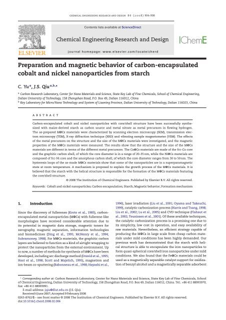
906 chemical engineering research <strong>and</strong> design 8 6 (2008) 904–908Fig. 2 – TEM images <strong>of</strong> the M@Cs samples: (a) <strong>and</strong> (b) Co@Cs; (c) <strong>and</strong> (d) Ni@Cs.sition <strong>of</strong> these tiny spots on the surface <strong>of</strong> the samples. Moredata is needed to clarify this, <strong>and</strong> the work is in progress now.Fig. 2 shows that the typical TEM images <strong>of</strong> the Co@Cs <strong>and</strong>Ni@Cs materials, showing that the Co@Cs materials with adiameter in a narrow range <strong>of</strong> 30–50 nm are spherical or quasisphericalin shape, <strong>and</strong> exhibit well-constructed core/shellstructure. The HRTEM examination (Fig. 2b) reveals that the<strong>carbon</strong> shells <strong>of</strong> Co@Cs are graphitic sheets, which is similarto the <strong>carbon</strong> shell structure <strong>of</strong> the Fe@Cs samples obtainedfrom starch in our previous study (Qiu et al., 2006a, submittedfor publication, in press). But this is not the case for the Ni@Csmaterials (Fig. 2c <strong>and</strong> d). The diameter <strong>of</strong> the Ni@Cs samplesvaries in a range <strong>of</strong> 200–500 nm, which is much bigger than that<strong>of</strong> the Co@Cs materials. The HRTEM images (Fig. 2d) show thatthe outside <strong>carbon</strong> layers <strong>of</strong> the Ni@Cs materials are amorphous<strong>carbon</strong>. This implies that the metal precursor specieshave a substantial influence on the diameter <strong>and</strong> <strong>carbon</strong> shellstructure <strong>of</strong> the M@Cs samples, which is further confirmed bythe XRD results discussed below.The XRD patterns <strong>of</strong> the as-prepared Co@Cs <strong>and</strong> Ni@Csmaterials are shown in Fig. 3, in which the peak at 25.6 ◦ inthe case <strong>of</strong> Co@Cs <strong>and</strong> Ni@Cs materials is due to the (0 0 2)diffraction <strong>of</strong> graphite layers. Nevertheless, the (0 0 2) peak <strong>of</strong>the Co@Cs materials is narrow <strong>and</strong> sharp in comparison to the(0 0 2) peak <strong>of</strong> Ni@Cs samples that is broader <strong>and</strong> lower, implyingthe Co@Cs materials have a high degree <strong>of</strong> graphitization.This is in agreement with the TEM results discussed above,i.e. the shell layer in the Co@Cs samples is made <strong>of</strong> graphiticsheets, while the shell layer in the Ni@Cs samples is made<strong>of</strong> amorphous <strong>carbon</strong>. For the Co@Cs material, the diffractionpeaks at 44.2 ◦ , 51.5 ◦ <strong>and</strong> 75.9 ◦ can be attributed to (1 1 1), (2 0 0)<strong>and</strong> (2 2 0) planes <strong>of</strong> fcc-Co, respectively (Sun et al., 1999). Whilein the case <strong>of</strong> the Ni@Cs material, the diffraction peaks at 44.4 ◦ ,51.8 ◦ <strong>and</strong> 76.3 ◦ are due to (1 1 1), (2 0 0) <strong>and</strong> (2 2 0) planes <strong>of</strong> fcc-Ni, respectively. It is also found that the relative intensity <strong>of</strong> themetal peaks varies depending on the different metal precursorsused. The fcc-Ni peak is stronger than the fcc-Co peak,implying that the diameter <strong>of</strong> nickel nanoparticles is biggerthan that <strong>of</strong> <strong>cobalt</strong> nanoparticles. With the Scherrer equation,the size <strong>of</strong> metal cores in the M@Cs samples can be calculatedfrom the XRD dada, i.e. on the basis <strong>of</strong> the (200) diffractionpeaks, the (1 1 1) <strong>and</strong> (2 0 0) diffraction peaks <strong>of</strong> fcc-Co or fcc-Ni. The calculated size <strong>of</strong> fcc-Co core in the Co@Cs samplesranges from 20 to 35 nm. While the calculated size <strong>of</strong> fcc-Nicore in the Ni@Cs samples is in a range <strong>of</strong> 30–50 nm. Here itshould be noted that there is a discrepancy between the XRDresults <strong>and</strong> the TEM results in terms <strong>of</strong> the size or diameter<strong>of</strong> the M@Cs. The reason behind this phenomenon may beFig. 3 – XRD patterns <strong>of</strong> the Co@Cs <strong>and</strong> Ni@Cs samples.
chemical engineering research <strong>and</strong> design 8 6 (2008) 904–908 907Fig. 4 – Magnetic hysteresis curves <strong>of</strong> (a) Co@Cs <strong>and</strong> (b) Ni@Cs samples measured at 25 ◦ C, <strong>and</strong> (c) photos <strong>of</strong> Co@Cs materialsin alcohol under the effect <strong>of</strong> a magnet bar outside the bottle, showing the M@Cs are <strong>magnetic</strong>ally separable.because the XRD technique gives rise to the average information<strong>of</strong> the samples while the TEM examination may partlyreveal the information <strong>of</strong> the diameter <strong>of</strong> the M@Cs particles,some <strong>of</strong> which may not be loaded onto the copper grid <strong>and</strong>may not be observed by the TEM.The VSM <strong>magnetic</strong> measurement results for the assynthesizedCo@Cs <strong>and</strong> Ni@Cs materials are shown in Fig. 4.The hysteresis loops <strong>of</strong> the as-made M@Cs materials revealthe intrinsic <strong>magnetic</strong> <strong>behavior</strong>, indicated by the saturationmagnetization (Ms), the remanent magnetization (Mr) <strong>and</strong>the coercive field (Hc) for the M@Cs samples. The ratio <strong>of</strong>remanence to saturation magnetization (Mr/Ms) <strong>of</strong> the Co@Cs<strong>and</strong> Ni@Cs samples is 0.131 <strong>and</strong> 0.109, respectively, indicatingthat the M@Cs samples made from the starch <strong>and</strong> nitrate aresuperpara<strong>magnetic</strong> at room temperature (Sajitha et al., 2004).The <strong>magnetic</strong> performance <strong>of</strong> the M@Cs samples was demonstratedin a liquid phase by placing a magnet bar near the glassbottle, showing clearly that the black powder, i.e. the M@Csmaterials could move under the <strong>magnetic</strong> force (see Fig. 4c).This makes the M@Cs materials ideal adsorbents <strong>and</strong> catalystsupports that are <strong>magnetic</strong>ally separable.The results presented here clearly show that the biomaterial,core-derived starch, can be used as <strong>carbon</strong> source forproducing Co@Cs or Ni@Cs samples. Efforts have been madeto figure out the possible mechanism involved in the formationprocess <strong>of</strong> the M@Cs materials. It is believed thatthe formation <strong>of</strong> metal core/<strong>carbon</strong> shell structure would berelated to the helical structure <strong>of</strong> the starch precursor. Theamylose starch is known to be capable <strong>of</strong> forming helical structures<strong>of</strong> variable pocket sizes according to the size <strong>of</strong> the hostbody. This helical structure would encapsulate metal clustersin the system, providing the possibility <strong>of</strong> forming thecore/shell structure with spherical or quasi-spherical morphology,evidenced by the previous studies (Qiu et al., 2006a,submitted for publication, in press; Sarma et al., 2004). It isknown that the thermal decomposition process <strong>of</strong> starch issimilar to that <strong>of</strong> cellulose, a kind <strong>of</strong> amylose (Bacon <strong>and</strong>Tang, 1964a,b; Qiu et al., 2006a; Sarma <strong>and</strong> Chattopadhyay,2004). During the preparation process, a series <strong>of</strong> reactionswould occur in the starch/metal <strong>carbon</strong>ization process, suchas desorption <strong>of</strong> physically adsorbed water, chain scissions<strong>and</strong> breaking <strong>of</strong> C O <strong>and</strong> C C bonds within ring units <strong>of</strong>the starch, yielding highly active species such as chain-like<strong>carbon</strong> molecules that would further polymerize to form thegraphite-like layer as the <strong>carbon</strong> shell structure observed inthe M@Cs materials. This process is like a catalytic graphiticprocess because <strong>of</strong> the presence <strong>of</strong> iron-group metals. Thestarch/metal composites undergo a stage in which they aretransformed to metal–<strong>carbon</strong> fused phase, <strong>and</strong> as the reactionscontinue, the supersaturated <strong>carbon</strong> would be formed<strong>and</strong> precipitated on the surface <strong>of</strong> the nanoparticles, resultingin the <strong>carbon</strong>-<strong>encapsulated</strong> metal nanoparticles (Tsai et al.,2000; Herring et al., 2003).4. ConclusionsThe M@Cs materials with a unique core/shell structure havebeen successfully prepared from the starch <strong>and</strong> the metalnitrate by <strong>carbon</strong>ization in flowing hydrogen. This providesa new approach to synthesis <strong>of</strong> <strong>carbon</strong>-<strong>encapsulated</strong> metalnanoparticles using the cheap biomaterials as <strong>carbon</strong> source.The SEM examination reveals that the M@Cs materials areellipsoidal in shape with the diameter being in a range <strong>of</strong>10–50 m. The XRD examination reveals that the Co@Cs materialsare made <strong>of</strong> the fcc-Co core <strong>and</strong> the graphitic shellstructure, with the metal core diameter being in a range <strong>of</strong>20–35 nm; while in the case <strong>of</strong> the Ni@Cs materials, the fcc-Nicore <strong>and</strong> the amorphous <strong>carbon</strong> shell are observed, with themetal core size varying from 30 to 50 nm. The starch used inthe present work has dual functions for the formation <strong>of</strong> M@Csmaterials that are superpara<strong>magnetic</strong> at room temperature:<strong>carbon</strong> precursor <strong>and</strong> stabilizer inhibiting the agglomeration<strong>of</strong> metal nanoparticles.


