OBD Operation Summary for 6.7L Diesel - MotorCraftService.com
OBD Operation Summary for 6.7L Diesel - MotorCraftService.com OBD Operation Summary for 6.7L Diesel - MotorCraftService.com
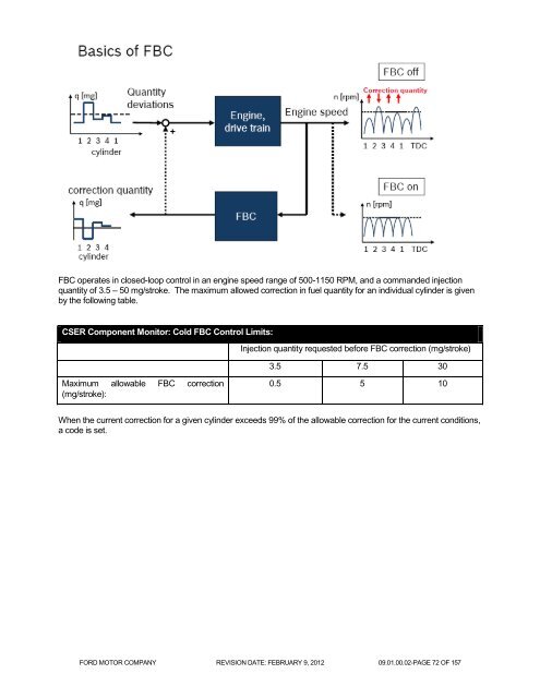
FBC operates in closed-loop control in an engine speed range of 500-1150 RPM, and a commanded injectionquantity of 3.5 – 50 mg/stroke. The maximum allowed correction in fuel quantity for an individual cylinder is givenby the following table.CSER Component Monitor: Cold FBC Control Limits:Injection quantity requested before FBC correction (mg/stroke)3.5 7.5 30Maximum allowable FBC correction(mg/stroke):0.5 5 10When the current correction for a given cylinder exceeds 99% of the allowable correction for the current conditions,a code is set.FORD MOTOR COMPANY REVISION DATE: FEBRUARY 9, 2012 09.01.00.02-PAGE 72 OF 157
CSER Component Monitor: Cold FBC Monitor Operation:DTCsMonitor ExecutionMonitor SequenceSensors OKTypical Monitoring DurationP0263 – Cylinder #1 Contribution/BalanceP0266 – Cylinder #2 Contribution/BalanceP0269 – Cylinder #3 Contribution/BalanceP0272 – Cylinder #4 Contribution/BalanceP0275 – Cylinder #5 Contribution/BalanceP0278 – Cylinder #6 Contribution/BalanceP0281 – Cylinder #7 Contribution/BalanceP0284 – Cylinder #8 Contribution/BalanceP0263 – During EOM3 after a cold startP0266 – During EOM3 after a cold startP0269 – During EOM3 after a cold startP0272 – During EOM3 after a cold startP0275 – During EOM3 after a cold startP0278 – During EOM3 after a cold startP0281 – During EOM3 after a cold startP0284 – During EOM3 after a cold startNoneCrankshaft Position Sensor "A" Circuit (P0335)Crankshaft Position Sensor "A" Circuit Range/Performance (P0336)10 secTypical CSER Component Monitor: Cold FBC Monitor Entry Conditions:Entry condition Minimum MaximumEOM3 ActiveEngine speed 500 rpm 1150 rpmInjection quantity 3.5 mg/stroke 30 mg/strokeEngine TemperatureBarometric PressureFBC wheel learn completeTypical CSER Component Monitor: Cold FBC Monitor Malfunction Thresholds:If the current correction for the injector exceeds 99% of the allowable correction for current operation conditions,the code is set.FORD MOTOR COMPANY REVISION DATE: FEBRUARY 9, 2012 09.01.00.02-PAGE 73 OF 157
- Page 22 and 23: Fuel Rail Pressure ( FRP ) Rational
- Page 24 and 25: Fuel Temperature Sensor Circuit Che
- Page 26 and 27: Fuel Pressure Control Valve (PCV) M
- Page 28 and 29: Fuel Injector Driver Circuit Monito
- Page 30 and 31: Injector Code Missing/Invalid:Injec
- Page 32 and 33: Injection Timing / Injection quanti
- Page 34 and 35: Feedback control:Fuel Balancing Con
- Page 36 and 37: VoltageNominal Voltage Calibration:
- Page 38 and 39: EXHAUST GAS SENSOR MONITORAir-Fuel
- Page 40 and 41: The NOx sensor is primarily used to
- Page 42 and 43: percent O2P0133 (O2 slow response)
- Page 44 and 45: EXHAUST GAS RECIRCULATION (EGR) SYS
- Page 46 and 47: EGR Cooler/ECB Entry Conditions (Ov
- Page 48 and 49: EGR System Slow ResponseSlow respon
- Page 50 and 51: Mass Airflow Closed-loop Control Li
- Page 52 and 53: Note: this monitor also serves to m
- Page 54 and 55: Functional Overboost MonitoringThe
- Page 56 and 57: Threshold Underboost MonitoringThe
- Page 58 and 59: PARTICULATE MATTER (PM) FILTER MONI
- Page 60 and 61: DPF Incomplete Regeneration Monitor
- Page 62 and 63: DPF Restriction MonitorThe DPF is m
- Page 64 and 65: Mass Air Flow Sensor Functional Che
- Page 66 and 67: Warm-up profiles with nominal therm
- Page 68 and 69: Primary Coolant Temp Dynamic Monito
- Page 70 and 71: COLD START EMISSION REDUCTION STRAT
- Page 74 and 75: Engine SensorsAir Temperature Ratio
- Page 76 and 77: Ambient Air Temperature (AAT) Senso
- Page 78 and 79: Charge Air Cooler Temperature (CACT
- Page 80 and 81: EGR Cooler Downstream Temperature R
- Page 82 and 83: Barometric Pressure and Manifold Ab
- Page 84 and 85: Turbine Upstream Pressure Sensor Pl
- Page 86 and 87: EGR Valve Position SensorAnalog inp
- Page 88 and 89: Engine Coolant & Engine Oil Correla
- Page 90 and 91: Engine Oil Temperature (EOT) Sensor
- Page 92 and 93: Typical Camshaft and Crankshaft Sen
- Page 94 and 95: Typical Fan and Fan Speed Sensor Ch
- Page 96 and 97: MAF Rationality CheckA rationality
- Page 98 and 99: Mass Air Flow Sensor Plausibility C
- Page 100 and 101: Reductant Pressure Sensor Signal Ra
- Page 102 and 103: DEF System Pressure ControlDEF pres
- Page 104 and 105: Reductant Tank Level Sensor Circuit
- Page 106 and 107: Reductant Tank Temperature Circuit
- Page 108 and 109: Exhaust Gas Temperature Sensor Rati
- Page 110 and 111: Exhaust Gas Temperature Rationality
- Page 112 and 113: Diesel Particulate Filter Pressure
- Page 114 and 115: Typical Actuator Jammed Valve Entry
- Page 116 and 117: ECB Valve Actuator Signal Range Che
- Page 118 and 119: Reductant Pump MotorThe Reductant P
- Page 120 and 121: Reductant Pump Motor Circuit Checks
FBC operates in closed-loop control in an engine speed range of 500-1150 RPM, and a <strong>com</strong>manded injectionquantity of 3.5 – 50 mg/stroke. The maximum allowed correction in fuel quantity <strong>for</strong> an individual cylinder is givenby the following table.CSER Component Monitor: Cold FBC Control Limits:Injection quantity requested be<strong>for</strong>e FBC correction (mg/stroke)3.5 7.5 30Maximum allowable FBC correction(mg/stroke):0.5 5 10When the current correction <strong>for</strong> a given cylinder exceeds 99% of the allowable correction <strong>for</strong> the current conditions,a code is set.FORD MOTOR COMPANY REVISION DATE: FEBRUARY 9, 2012 09.01.00.02-PAGE 72 OF 157


