
You also want an ePaper? Increase the reach of your titles
YUMPU automatically turns print PDFs into web optimized ePapers that Google loves.
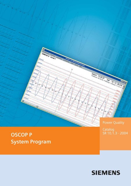
Power Quality<strong>OSCOP</strong> P<strong>System</strong> <strong>Program</strong>CatalogSR 10.1.3 · 2004
<strong>OSCOP</strong> P <strong>System</strong> <strong>Program</strong>Applications<strong>OSCOP</strong> P system program<strong>OSCOP</strong> P is a PC program forretrieving and processingof records made with theSIMEAS R digital fault andpower quality recorder, theSIMEAS Q power qualityrecorder, or with numericalprotection relays using theIEC 60870-5-103 protocol.The following tasks can beperformed manually or automaticallyusing <strong>OSCOP</strong> P: Retrieving measurementdata from connected devicesand storing it in thedatabase Evaluation of data Visualization of results Output of results via a faxor printer Archiving of recordsAppropriate installation ofthe <strong>OSCOP</strong> P on applicationspecificPC hardware enablesthe fault recorder system toperform its task without interruption.DAKON-PCA number of devices(SIMEAS R, SIMEAS Q, protectionrelays) can be connectedto a data concentratorPC (called the DAKON PC).A DAKON-PC can collect therequired data and automaticallypass them on to a serverPC.Server PCA number of DAKON PCs canbe connected to one serverPC. Data from the server PCcan be retrieved and evaluatedby several connectedclient PCs.One server PC can pass onthe collected data to a higherlevelserver PC.Evaluation PCA number of DAKON PCs,SIMEAS Rs and SIMEAS Qs canbe connected to one evaluationPC. This configuration isprimarily for local parameterizationand data evaluation. Anevaluation PC can also be installedin the office andconnected to a DAKON PC orserver PC.Client PCA client PC is connected to aserver PC and is used for dataevaluation. The client PC cannotpass on data to higher-levelPCs.Client-server networkAll the above PCs can be interconnectedvia an Ethernetprotocol. This ensures fastdata exchange, e.g. betweenthe PCs in several substationsand a central server.Data transferThe remote data transferbetween the PC and theconnected units can be fullyautomatic. Here are someexamples of possible communicationlinks: Direct link, e.g. connectionof numerical protectionrelays to an RS232 interfacevia a star coupler Connection of SIMEAS R andSIMEAS Q units via an analogor ISDN modem andpublic telephone network Networking of several evaluationPCs, DAKON PCs,server PCs and SIMEAS R viathe Ethernet with the TCP/IPprotocol.Automatic operation<strong>OSCOP</strong> P can be parameterizedto perform many taskseither manually or automatically.Complete automationof tasks – such as retrievingdata, evaluation, on-screendisplay, printing and faxing –can reduce the user's workload.Addressing a devicespecifically and analyzing itsdata can also be performedmanually.Evaluation programThe evaluation program allowssimultaneous display ofany number of curves in anycombination. Easy-to-usezoom functions, grid lines,several measuring cursors andadditional calculations for diversepower system variablesenable optimum evaluationof power system faults. Viathe clipboard function, extractsfrom records can bere-used for a report in nearlyall Windows applications,for example MS Word.Peripheral equipment<strong>OSCOP</strong> P can address all peripheraldevices such asprinters and faxes supportedby the operating system.Data processing<strong>OSCOP</strong> P can perform thetasks of collecting data,writing it to the database,evaluating it, visualizing it,printing it and faxing it. Thisensures uninterruptedfunctioning of the installedfault recorder system withoutintervention by maintenancepersonnel.Supplementary functions(options)DIAGNOSE (fault locator)The optional “DIAGNOSE”software module performsautomatic analysis of the faultrecords of power transmissionand distribution lines. Thisfunction serves to compute afault location on the line.The result is presented in cleartext. As part of the parameterization,the line can be dividedinto several segments tofacilitate fault localization (appliesto one-end calculationonly). If the current and voltagesof a parallel line are recorded,the inductive effect isautomatically taken intoaccount. If the data relatingto a fault are available at bothends of a transmission line,the fault location can be determinedmore accuratelyfrom two sources. When parameterizedaccordingly, andwith automatic data transfer,these functions are performedautomatically. If desired, theresults are logically linked tothe fault record and automaticallyprinted or displayed onthe monitor.Power system faults can befiltered selectively to savetime. Experts can then concentratetheir efforts on morecomplex events.Importing and exporting dataThe additional “data import”function permits processing ofevents that have beenrecorded by devices of othermanufacturers in <strong>OSCOP</strong> P.These data must be inComtrade or ASCII format.The data are imported by<strong>OSCOP</strong> P and are available forfurther processing.The additional “export” functioncan provide from theSIMEAS R in the above formatto other programs.<strong>Siemens</strong> SR 10.1.3 · 2004 3
<strong>OSCOP</strong> P <strong>System</strong> <strong>Program</strong>ApplicationsSupplementaryfunctions (cont’d)SICARO PQ analysis ofpower qualityThis software packagepermits analysis ofSIMEAS R measurementdata (rms voltage andcurrent, frequency,THD, active and reactivepower, etc.) based on thepower quality standardEN 50160 or freely definablelimits. The measuredvalues are automaticallycompared with the setpointsand evaluated.After analysis, a report isautomatically generatedby the software, its structureand layout havingbeen predefined by theuser. It is also possible toconvert the completedreport to HTML format. Inthis format the report canbe easily sent via e-mail.The HTML report can bevisualized and printed outusing an Internet browser.SICARO PQ also permitsanalysis of data measuredby SIMEAS Q quality recorders.In conjunctionwith <strong>OSCOP</strong> P, measuredvalues can be retrievedand analyzed automatically.The SICARO PQsoftware package is alsoavailable as singlelicense software, permittingpower quality analysiseven without an <strong>OSCOP</strong> Plicense. However,automated operation isthen not supported andthe data required forpower quality analysismust be provided in files.ParameterizationOne important componentof the parameterizationis the definition ofthe network topology,followed by assignment ofdevices. The communicationstructure with individualdevices and other PCsmust then be configuredin the <strong>OSCOP</strong> P program.When these steps havebeen performed each individualdevice can then beparameterized.Definition of networktopology– Region(s)– Substation(s)– Feeder(s)– Followed by assignmentof each device to a region,substation, feederand voltage levelType of communicationlink to the PC per device:– Null modem (direct link)– Dedicated line modem– Analog modem, includingtelephone number– ISDN modem, includingISDN number– Ethernet link (LAN/WAN), including TCP/IPnumber– X.25 network, includingX.25 addressDevice password:– For each SIMEAS R– For each protectionrelaySerial PC interfaces perdevice– Address (in the PC)– Baud rate– Number of data bits– Number of stop bits– ParitySR13118.tifSR13119.tifFig. 2Fig. 3Assignment of devices to feeders and substationsConnection parametersSR13120.tifFig. 4Parameters for SIMEAS R / system control4 <strong>Siemens</strong> SR 10.1.3 · 2004
<strong>OSCOP</strong> P <strong>System</strong> <strong>Program</strong>FeaturesParameterization (cont’d)<strong>Program</strong> passwordDepending on the requirements,different rights canbe assigned to each user.This ensures coordinatedparameterization of devices.The intention is toavoid non-harmonizedparameterization of identicaldevices from differentPCs.The following access rightscan be assigned:a) Access to all functions ispermittedb) PC parameterization isdisabledc) Device parameterizationand diagnosis aredisabled, plus b)d) All delete functions aredisabled, plus c)e) Retrieving data fromlower-level PCs isdisabled, plus d)Storage of files / data base:– Name of drive for storingthe data– Limitation of the databasein MbytesLanguage setting for userinterface– English– German– French– Spanish– ItalianParameterization of theSIMEAS R digital fault andpower quality recorder– Device designation– Short identification of ameasurement channel– Channel legend– Measuring range of ameasurement channel– Dimension of a measurementchannel– Color of a measurementchannel– <strong>System</strong> time– Storage capacity per recordingfunction– Transmission type(ASCII or binary)– Local printerActivation of the functions– Fault recorder– Power and frequencyrecorder– Mean value and powerquality recorder– Voltage dip and flicker– Event recorder– Report printer Parameterization of thefault record– Trigger values– Pre-fault recording– Recording times– Trigger disableFig. 5Fig. 6SIMEAS R parameters/fault recorder/trigger settingsSIMEAS R parameters/power/frequency recorderSR13121.tifSR13122.tifSR13123.tifFig. 7Parameters of the output devices<strong>Siemens</strong> SR 10.1.3 · 2004 5
<strong>OSCOP</strong> P <strong>System</strong> <strong>Program</strong>FeaturesParameters forautomatic functionsFault recordings can beautomatically displayed onthe screen, printed, faxed andexported in a predefined format.Printing– Fault records on/off perdevice– RMS value curve or sinewave per device– Number of curves per sheet– Max. number of sheets– Time scale– Amplitude scale– Color display on/off– Event log on/off per deviceFax transmission– Telephone number for eachfax terminal– Designation of the faxterminal– Assignment of a device tothe fax terminal– Fault record on/off perdevice– RMS value curve or sinewaves per device– Event log on/off per deviceDisplay on the monitor– Fault records on/off perdevice– RMS value curve or sinewaves per device– Event log on/off per deviceDiagnostic function(option)– Diagnostic function on/offper device– Print-out on/off per device– Output on monitor on/offper deviceExport functions(ASCII, Comtrade)– On/off per data type anddevice– Indication of target driveand directorySR13124.tifSR13125.tifFig. 8Fig. 9Sequence control system of automatic modeZoomed display of the current and voltage of a phase(with grid lines)SR13126.tifFig. 10 RMS value of a three-pole fault6 <strong>Siemens</strong> SR 10.1.3 · 2004
<strong>OSCOP</strong> P <strong>System</strong> <strong>Program</strong>FeaturesAutomatic and manual datatransferOne or more SIMEAS Rs can beconnected to a DAKON PC orserver PC. Data transfer maybe manual or automatic. Aserver PC retrieves the data eitherdirectly from the SIMEAS Ror via a DAKON PC. Here aresome examples of settings fordata transfer.Automatic data transfer– Interrogation of all orselected systems– Continuous operation via allavailable communicationschannels– Time-controlled operation– Transfer of header data withevent information only– Transfer of rms value curveof DAKON PC only– Transfer of diagnosis resultof DAKON PC only– Transfer of a combination ofthe rms value curve or sinewave with the results of diagnosis– Matching of the parametersbetween SIMEAS R,DAKON PC and <strong>OSCOP</strong> PManual sorting of records/filtering function:– Sorting by region– Sorting by substation– Sorting by voltage level– Sorting by cause ofrecording– Sorting by date and time– Header data transfer– Measurement data transfer– Local print-out of events– Local deletion of events– Deletion of all manual starts– Directory of all events– Retrieve diagnosis results ofDAKON PC– Retriev rms value curve ofDAKON PC– Measuring signals (sinewave)– Combination of measuringsignal and rms value curvewith diagnosis results– Interrogation of the status ofSIMEAS R and DAKON PCFig. 11 Example of a measurement by cursor with vector diagramFig. 12 Example of diagnosis resultsFig. 13 Example of a protection relay event logSR13129.tif SR13128.tif SR13127.tif<strong>Siemens</strong> SR 10.1.3 · 2004 7
<strong>OSCOP</strong> P <strong>System</strong> <strong>Program</strong>FeaturesEvaluationSelection of the recording– Extensive filtering functioncovering region, substation,voltage level, feeder, dateand time window, type ofevent, type of device, etc.– All or selected channels– Mixing of different systemsand channels– Changing the channeldesignation– Changing the color of achannelDisplay– RMS value curve– Instantaneous value curve(sine wave)– Computed phase-to-phasevoltages as instantaneous orrms value– Instantaneous values withgrid lines– Instantaneous values ofseveral superimposedcurves each with scaling– Computed differential quotient(M/t) as a curvewith time interval settablefrom 1ms to 99999 s– Computed relative deviation(M/M) as a curve– Computed absolute deviation(M) as a curveZoom function(positive and negative)– Amplitude and time axis– General zoom– Channel-specific zoom(for enlarging very smallindividual signals)– Window zoom (magnifyingfunction)– Horizontal zoom– Vertical zoomMoving individually selectedchannels– In x-direction– In y-direction– In x- and y-directionsMeasuring– Eight measuring valuecursors for instantaneousvalue and time (includingdifferences between thecursors)– Trigger line (can also beused as a measuring valuecursor)– Data records can be movedfrom the value window tothe clipboard and can thenbe integrated in a report.Computation with referenceto the cursor positionCalculation of all values is updatedwith cursor movements– Amplitudes and rms values– Phase angle and power factor(p.f.) (cos ) relative toany channel– Impedance and reactancebetween one phase andearth– Impedance and reactancebetween two phases– Active, reactive and apparentpower; single orthree-phase– Voltage symmetry– Vector diagram with selectedcurves (one curve isdefined as the reference)– 1st to 21st order harmonicsand DC components aspercentage or rms value– Total harmonic distortionPrint-out of the rms valuecurves– Print layout correspondingto the window contents onthe monitor– Complete print-out from thebeginning to the end of recordingPrint-out of the instantaneousvalue curve– Print layout correspondingto the window contents onthe monitor (full graphicresolution, no hardcopy)– Complete print-out from thebeginning to the end of therecording– Print-out of the instantaneousvalue curve, includingthe computed curves (e.g.calculation of thephase-to-phase voltagesfrom the phase-to-earthvoltages)– Print-out of all initially selectedcurves between twocursors– All computed values in tableform– Vector diagramsTo transfer the window contentsto other Windows applicationswith the highestpossible graphic resolution,the clipboard function of theWindows operating system isused. A typical example iswriting a report using a wordprocessing program (for exampleMS Word).PrintingOn printers (also color)supported by the Windowsoperating system:– All system parameters– All curves– All event logs– All computed values– All tables and– Vector diagramsAutomatic print-out anddisplay on the monitorFor the various possibilities,see parameters for the automaticfunctionsMeasured-value andparameter files Import and export of measured-valueand parameterfiles from diskette or harddisk Annotation of measuredvaluefiles with comments8 <strong>Siemens</strong> SR 10.1.3 · 2004
<strong>OSCOP</strong> P <strong>System</strong> <strong>Program</strong>Method of OperationDIAGNOSE with faultlocatingfunction for transmissionlines (option)The optional DIAGNOSE softwarepackage is used with<strong>OSCOP</strong> P for calculating faultlocations on a transmissionline after a short-circuit.DIAGNOSE is software thatsupports the user in routinework. This module providesextensive setting options tocalculate the fault location asaccurately as possible.Line segmentsThis module permits entry ofseveral line segments, to takeaccount of their differingproperties, e.g. overhead lineand buried cable segments.Parallel linesIn the event of a fault on aline, the absolute error of thecalculated fault location maybe substantial if the inductivecoupling of the parallel line isnot taken into account. If theparameters of a parallel lineare known, it is possible to improvethe accuracy of thecalculated fault location withcorrect parameterization ofthe DIAGNOSE program.Double-end computation ofthe fault locationIf the current and voltagesignals of a line are registeredat both ends by differentSIMEAS Rs during a shortcircuit,the fault location canbe computed by evaluatingboth recordings. This calculationusually leads to a moreaccurate fault location.Appropriate parameterizationof the substation and deviceassignment activates double-endcomputation.ResultsThe result is output as an absolutevalue in km and as impedancein ohms. The faulttype (e.g. phase L1-L2) is assignedto the measured-valuefiles with a distance in km. Onrequest, the peak and rms valueswith phase angle arespecified before and duringthe fault and the active, reactiveand apparent power before,during and after thefault. The diagnostic result isdisplayed on the screen inclear text or output on theprinter. With appropriateparameterization the resultcan be faxed via a DAKON PCor server PC. The explanatorycomponent is implemented asa graphic curve display. Besidesthe fault location, timedata concerning rapid autoreclosure(RAR) and automaticreclosures (ARC) are stated.AccuracyFor one-end fault localization,the error is typically 5 % withcorrect parameterization andlow-resistance short-circuits.The algorithm used providesdata about the accuracy of thefault location calculation (reliabilitydata in %).Parameters for the diagnosticmoduleThe following parameters canbe defined for the diagnosticmodule: Rated frequency Single or parallel line One or two-end calculationof the fault locations (only ifrecording devices have beeninstalled at both ends) Number of line segments(for one-end calculationonly) Line length per segment(for one-end calculationonly) Positive sequence impedanceper segment Negative sequenceimpedance per segment Allocation of the feedercurrents to the respectivevoltagesSeveral parameter sets arepossible per line; for example,the different line parametersfor single or parallel linecalculation. Changeover isperformed manually.The diagnostic softwareworks either automatically ormanually.Data required for a single line:– Phase currents L1, L2, L3– Phase-to-earth voltages V L1 ,V L2 , V L3Data required for a parallelline:– Phase currents L1, L2, L3per line– Phase-to-earth voltages V L1 ,V L2 , V L3 from busbar or perlineAdditional function: Importand export of data (option)With this additional module,all fault events can be importedand exported in astandard format complyingwith the international IEEEstandard (Comtrade or ASCIIformat). This allows import offault events from another deviceor system for processingwith <strong>OSCOP</strong> P. Fault eventsexported according to thisstandard can be used for testingnumerical protectionrelays with the aid of appropriateequipment.Additional function:SICARO PQ analysis ofpower system quality(option)SICARO PQ permits automatedanalysis of data andalso generates an analysisreport. The criteria for theevaluation of the analysisare limit values specified inthe EN 50160 standard.This standard is preset, butanalysis on the basis of application-specificlimit values isalso possible.Networking of evaluationstations<strong>OSCOP</strong> P expansion level“Server” permits design ofa network of evaluationstations via a LAN or WAN(TCP/IP). In this case, a serverPC or a DAKON PC is used asthe server. All fault events ofthe connected fault recordersor numerical protection relays(IEC 60870-5-103) are readinto the database and archivedby this server.<strong>OSCOP</strong> P can then run on anynumber of client PCs withinthe network (10 licenses arepossible in the basic version).Due to the fact that <strong>OSCOP</strong> Pis installed completely at eachworkstation, autonomousdata archiving is possiblethroughout a company, e.g.according to differentareas of responsibility.<strong>Siemens</strong> SR 10.1.3 · 2004 9
<strong>OSCOP</strong> P <strong>System</strong> <strong>Program</strong>Configuration InformationOperating system– Windows 98 SE(DAKON 98 only)– Windows NT 4.0– Windows 2000– Windows XP ProfessionalHardware requirementsEvaluation PC / Client PC– Personal computer, 500 MHzprocessor or better– RAM 128 Mbytes– Hard disk, recommendedminimum 10 Gbytes– Color graphic card VGA orS-VGA– Printers supported by theWindows operating system– Mouse / keyboard for operation– Network card as requiredDAKON PC / Server PC– Personal computer, 2 GHzprocessor or better– RAM 512 Mbytes– Hard disk, recommendedminimum 40 Gbytes– Network card as required– Color graphic card VGA orS-VGA– Printers supported by theWindows operating system– Mouse / keyboard for operation10 <strong>Siemens</strong> SR 10.1.3 · 2004
<strong>OSCOP</strong> P <strong>System</strong> <strong>Program</strong>Selection and Ordering DataDescription Order No. Description Order No.<strong>OSCOP</strong> P 6.40 system program7KE6010-1 - For evaluation PCVersion 1 with database for a max. of 1 device 1) A 0 BVersion 2 with database for a max. of 5 devices 1) B 0 BVersion 3 with database for a max. of 10 devices 1) C 0 BVersion 4 with database for a max. of 1000 devices 1) DFor DAKON PCWith database for a max. of 1000 devices 1)Version 5 with IEC 60870-5-103 protocol forcommunication with numerical protectiondevices E 0 BFor Server PC + 10 clientsVersion 6 with database for a max. of 1000 devices 1)Communication server incl. 10 network clients.With IEC 60870-5-103 interface for communicationwith numerical protection devicesFAdditional function 1With diagnosis and fault locatorWithoutAdditional function 2With import and export of fault data in data formatin accordance with the IEEE Comtrade standard 1Without 0Additional function 3With SICARO PQ analysis of network qualityin accordance with EN 50160 standard and IEC 1000-2-2 1Without 0Additional function 4 (server PC only)With SICAM Archive, additional function 2 2) included 1Without 2Additional function 5 (server PC only)With COMTRADE Archive, additional function 2 2) includedWithoutManualGermanEnglishFrenchSpanishItalianAB0 BABABCDE<strong>OSCOP</strong>P6.40,dongle-free version 7KE6010-2AA00 -0A -ZX01For users with a license agreement fora version without dongle. The order isonly valid if a copy of the signed licenseagreement is sent to the factory.ManualGermanEnglishFrenchSpanishItalianSupplied on the following data media:On CD-ROM 0<strong>OSCOP</strong> P upgrade 6.x7KE6010-3A Upgrade of an existing dongle-connected<strong>OSCOP</strong> P license to a higher level.Delivery comprises a software to reprogramthe dongle for <strong>OSCOP</strong> P.No dongle will be supplied.An <strong>OSCOP</strong> P update-CD or a manual must beordered separately, if required.When placing a purchase order,please always submit the serial numberof the original <strong>OSCOP</strong> P license.Level 1 to level 2Level 1 to level 3Level 1 to level 4Level 1 to level 5Level 1 to level 6Level 2 to level 3Level 2 to level 4Level 2 to level 5Level 2 to level 6Level 3 to level 4Level 3 to level 5Level 3 to level 6Level 4 to level 5Level 4 to level 6Level 5 to level 6ABCDEFGHJKLMNPSupplied on the following data media:On floppy disks 1QABCDESupplied on the following data media:On CD-ROM 0(including manual in printed form and inthe corresponding language)1) Device: SIMEAS R, OSCILLOSTORE P531, protection device withIEC 60870-5-103 interface, unlimited number of SIMEAS Q.2) The application of this function must be clarified with the <strong>Siemens</strong>Product Management before ordering.Version 6.40 released only for operating systems Windows 2000 andWindows XP; not released for DAKON 98.<strong>Siemens</strong> SR 10.1.3 · 2004 11
<strong>OSCOP</strong> P <strong>System</strong> <strong>Program</strong>Selection and Ordering DataDescriptionOrder No.DescriptionOrder No.<strong>OSCOP</strong> P 6.40 – Additional functions 6.40KE6010-4AFor the enhancement of the functionalityof <strong>OSCOP</strong> P version 6.40; available as single licenseafter the first installation.Delivery comprises a software to reprogramthe dongle for <strong>OSCOP</strong> P.No dongle will be supplied.The corresponding software modules canbe found on the original CD (except for SICARO PQ).When ordering SICARO PQ, the current version of thesoftware will be supplied on documentation CD + floppy disk,manual in German and English contained ondocumentation CD. If required, <strong>OSCOP</strong> P update CD or manualhave to be ordered separately.When placing a purchase order,please always submit the serial numberof the original <strong>OSCOP</strong> P license.Diagnosis with fault locatorACOMTRADE Routinesfor data import und exportBSICARO PQ - Analysis of network qualityCSICAM Archive incl. option B 1)DCOMTRADE Archive incl. option B 1)(for server PC only)ESupplied on the following data mediaOn floppy disks 1NotePlease note that ordering of additional functions is onlypossible if you have an original <strong>OSCOP</strong> P license + dongle.1) The application of this function must be clarified withthe <strong>Siemens</strong> Product Management before ordering.<strong>OSCOP</strong> P 6.40 – Update OLD7KE6010-5AUpdate of an older <strong>OSCOP</strong> P version(versions: 3.x; 5.x; 6.0) to the 6.40 versionof the same level.Delivery comprises a new dongle, <strong>OSCOP</strong> P 6.40on data media and a manual.When placing a purchase order, please always submitthe serial number of the original <strong>OSCOP</strong> P license.The old dongle has to be returned to <strong>Siemens</strong>.Note:<strong>OSCOP</strong> P has to be reinstalled completely.ManualGermanEnglishFrenchSpanishItalianSupplied on the following data mediaCD-ROM 0ABCDE<strong>OSCOP</strong> P update 6.40Update for the 6.1x; 6.3x; 6.40x versionsto the current 6.40 version.Dongle-connected versionOnly for users with an older version of the<strong>OSCOP</strong> P 6.1.x / 6.3.x / 6.40.xSupplied without dongle;manual on documentation CDCurrent version of <strong>OSCOP</strong> P 6.40 on CDC53207-A409-D997-1Dongle-free versionOnly for users with a signed license agreementfor the version of <strong>OSCOP</strong> P 6.1.x/6.3.x/6.40.x without dongleSupplied with manual on documentation CDCurrent version of <strong>OSCOP</strong> P 6.4 on CD C53207-A409-D998-1Version 6.40 released only for operating systemsWindows 2000 and Windows XP; not released forDAKON 98.<strong>OSCOP</strong> P update 6.3Update for the older versions 6.1.x/6.3.xto the current 6.3 versionDongle-connected versionOnly for users with an older version of the<strong>OSCOP</strong> P 6.1.x/6.3.xSupplied without dongle; manual on documentation CDCurrent version of <strong>OSCOP</strong> P 6.3 on floppy disk C53207-A409-D993-1Current version of <strong>OSCOP</strong> 6.3 on CDC53207-A409-D994-1Dongle-free versionOnly for users with a signed license agreementfor the versions of <strong>OSCOP</strong> P 6.1.x / 6.3.x / 6.40.xwithout dongleSupplied with manual on documentation CDCurrent version of <strong>OSCOP</strong> P 6.3 on floppy disk C53207-A409-D995-1Current version of <strong>OSCOP</strong> P 6.3 on CD C53207-A409-D996-1<strong>OSCOP</strong> P update 6.1Update for the older version 6.1.xto the current 6.1 versionDongle-connected versionOnly for users with an older version of <strong>OSCOP</strong> P 6.1Supplied without dongle; manual on documentation CDCurrent version of <strong>OSCOP</strong> P 6.1 on floppy disk C53207-A409-D984-1Current version of <strong>OSCOP</strong> 6.1 on CDC53207-A409-D985-1Dongle-free versionOnly for users with a signed license agreementfor the version of <strong>OSCOP</strong> P 6.1.x without dongleSupplied without dongle; manual on documentation CDCurrent version of <strong>OSCOP</strong> P 6.1 on floppy disk C53207-A409-D986-1Current version of <strong>OSCOP</strong> P 6.1 on CD C53207-A409-D987-112 <strong>Siemens</strong> SR 10.1.3 · 2004
If you have any questions aboutPower Transmission and Distribution,our Customer Support Centeris available around the clock.Tel: +49 180 / 524 70 00Fax: +49 180 / 524 24 71E-Mail: support@ptd.siemens.dewww.siemens.com/ptd-support(Subject to charges,e.g.: 12 ct/min.)Published by<strong>Siemens</strong> AktiengesellschaftPower Transmission and DistributionPower Automation DivisionPostfach 48 0690026 NuernbergGermanywww.siemens.com/ptdOrder No.: E50001-K4013-A101-A4-7600