Create successful ePaper yourself
Turn your PDF publications into a flip-book with our unique Google optimized e-Paper software.
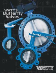
Page 4WS 1.5EE/<strong>2LEE</strong> Man u alInstaller Display SettingsOne of three sets of displays will be shown depending on what was selected in Configuration Settings Step 3CS.Volume (Gallons) selected in Configuration Settings Step 3CSStep 1IStep 1I - To enter Installer Display press the NEXT and▲ buttons simultaneously for 5 seconds and release.Step 2IStep 2I - Volumetric capacity in gallons to regeneration.Press NEXT to go to Step 3I. Press REGEN to exitInstaller Display.Step 3IStep 3I - Adjust day override from 1 - 28 or OFF.Press NEXT to go to Step 4I. Press REGEN to return toprevious step.Step 4IStep 4I - Use ▲ or ▼ buttons to set the regen hour.Press NEXT to go to Step 5I. Press REGEN to return tothe previous step.Step 5IEXIT TODISPLAYSCREENSStep 5I - Use ▲ or ▼ buttons to set the regen minutes.Press NEXT to exit Installer Display. Press REGEN toreturn to previous step.28 Day or 28/Volume (Gallons) selected in Configuration Settings Step 3CSStep 1IStep 1I - To enter Installer Display press the NEXT and▲ buttons simultaneously for five seconds and release.Step 2IStep 2I - Adjust days from 1 - 28. Press NEXT to go toStep 3I. Press REGEN to exit Installer Display.Step 3IStep 3I - Use ▲ or ▼ buttons to set time of the regenhour. Press NEXT to go to Step 4I. Press REGEN to returnto previous step.Step 4IEXIT TODISPLAYSCREENSStep 4I - Use ▲ and ▼ buttons to set the regen minutes.Press NEXT to exit Installer Display. Press REGEN toreturn to previous step.
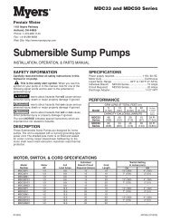
WS 1.5EE/<strong>2LEE</strong> Man u al Page 57 Day or 7/Volume (Gallons) selected in Configuration Settings Step 3CSStep 1IStep 1I - To enter Installer Display press the NEXT and▲ buttons simultaneously for 5 seconds and release.Step 2IStep 3IStep 2I - Use ▲ or ▼ buttons to set the current day ofthe week.Default = 2 (Monday)1 = SUNDAY2 = MONDAY3 = TUESDAY4 = WEDNESDAY5 = THURSDAY6 = FRIDAY7 = SATURDAYPress NEXT to go to Step 3I. Press REGEN to exitInstaller Display.Step 3I - Scroll through days 1 to 7 using the NEXTbutton. Use the ▲ or ▼ buttons to turn regen on oroff for each individual day (regen indicator on meansregeneration will happen). After completing the 7th day,press NEXT to go to Step 4I. Press REGEN to go toprevious display.Step 4IStep 4I - Use the ▲ or ▼ buttons to setthe regen hour. Press NEXT to go to Step 5I.Press REGEN to go to previous display.Step 5IStep 5I - Use the ▲ or ▼ buttons to set theregen minutes. Press NEXT to exit InstallerDisplay. Press REGEN to return to previousdisplay.EXIT TODISPLAYSCREENS
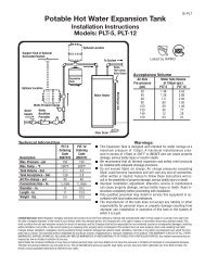
Page 6WS 1.5EE/<strong>2LEE</strong> Man u alSetting Regeneration Cycle TimesStep 1CTStep 2CTStep 1CT - Press NEXT and ▼ simultaneously for 5seconds and release. If screen in Step 2CT does not appear,the lock on the valve is activated. To unlock press ▼,NEXT, REGEN, ▲ in sequence, then press NEXT and ▼simultaneously for 5 seconds and release.Step 2CT - Adjust the length of the backwash from 1-20minutes or OFF using the ▲ or ▼ buttons.Press NEXT to go to Step 3CT. Press REGEN to exitRegeneration Cycle Times.Step 3CTStep 3CT - Adjust the length of the regenerant drawfrom 1-99 minutes or OFF using the ▲ or ▼ buttons.Press NEXT to go to Step 4 CT. Press REGEN to returnto previous step.Step 4CTStep 4CT - Adjust the length of the second backwashfrom 1-20 minutes or OFF using the ▲ or ▼ buttons.Press NEXT to go to Step 5 CT. Press REGEN to returnto previous step.Step 5CTStep 5CT - Adjust the length of rinse from 1-20minutes or OFF using the ▲ or ▼ buttons.Press NEXT to go to Step 6 CT. Press REGEN to returnto previous step.Step 6CTStep 6CT - Adjust the length of fill from 0.1-99.9minutes or OFF. Regenerant refills at a rate of 0.5 gpm,1.9 lpm.EXIT TODISPLAYSCREENSPress NEXT to exit Regeneration Cycle Times. PressREGEN to return to previous step.
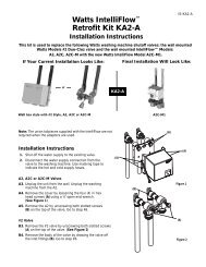
WS 1.5EE/<strong>2LEE</strong> Man u al Page 7Configuration SettingsStep 1CSStep 1CS – Press ▲ and ▼ buttons simultaneously for 5 seconds and release.If screen in Step 2CS does not appear, the lock on the valve is activated. Tounlock press ▼, NEXT, REGEN, ▲ in sequence, then press ▲ and ▼ buttonssimultaneously for 5 seconds and release.Step 2CSStep 3CSStep 4CSStep 2CS – Choose 1.5 for 1.5” or 2.0 for 2L. Press NEXT to go to Step 3CS.Press REGEN to exit Configuration Settings.Step 3CS – Press the ▲ or ▼ buttons to select one of the following:• If Volume (gallons) is selected the regeneration will occur after the specificvolume has been used or on the day override (if selected) whichever comes first.• If 28 is selected the regeneration will occur on the day (1 through 28) selectedin Installer Display Settings. The total flow and flow rate user displays and thevolume display in Diagnostics will not be shown even if a meter is used.• If 28/Volume (gallons) is selected the regeneration will occur on the day (1through 28) selected in Installer Display Settings. If a meter is not used the totalflow and flow rate user displays and the volume display in Diagnostics will beshown as 0.• If 7 is selected the regeneration will occur on the selected day(s) of the week(see instructions contained in Installer Display Settings). The total flow and flowrate user displays and the volume display in Diagnostics will not be shown evenif a meter is used.• If 7/Volume (gallons) is selected the regeneration will occur on the selectedday(s) of the week (see instructions contained in Installer Display Settings). Ifa meter is not used the total flow and flow rate user displays and the volumedisplay in Diagnostics will be shown as 0.Press NEXT to go to Step 4CS. Press REGEN to return to previous step.Step 4CS – Press the ▲ or ▼ buttons to select to regenerate immediately on 0or at delayed time. Immediately on 0 can only be selected if Volume (gallons) wasselected in step 3CS and a meter must be installed. Delay is the only option forthe other Step 3CS selections. Press NEXT to go to Step 5CS. Press REGEN toreturn to previous step.EXIT TODISPLAYSCREENSStep 5CSStep 5CS – Allows selection of one of the following:• an outside signal to initiate a regeneration; or• the Control Valve to act as an alternator.Selecting the use of an outside signal to initiate a regeneration: The outside signalis obtained by connection to the two prong connector labeled DP SWITCH onthe circuit board. Two types of regeneration initiation are available: immediateor delayed. If dP and Set annotator are displayed regeneration will occurimmediately after receiving a 2 minute input signal. The display at the left showsthe example of immediate regeneration. If dP, Regen annotator, Set annotatorand Time annotator are displayed regeneration will occur at the next scheduledregeneration time after receiving a 2 minute input signal.Selecting the Control Valve to act as an alternator:Note: In Step 3CS you must select Volume, Step 4CS select RegenerationTime Option “on O” and in Step 3I select Day Override “oFF”.Select ALTA for the control valve that has the two pin connector labeled DRIVEconnected to the alternator valve motor.Select ALTb for the control valve that will not be connected to the alternator valvemotor.Press NEXT to exit Configuration Settings. Press REGEN to return to previousstep.
Page 8WS 1.5EE/<strong>2LEE</strong> Man u alDiagnosticsStep 1DStep 1D - Press ▲ and ▼ buttons simultaneously for5 seconds and release. Then press ▲ and ▼ buttonssimultaneously for 2 seconds and release. If screenin Step 2D does not appear the lock on the valve isactivated. To unlock press ▼, NEXT, REGEN, ▲ insequence, then press ▲ and ▼ buttons simultaneouslyfor 5 seconds and release. Then press ▲ and ▼ buttonssimultaneously for 2 seconds and release.Step 2DStep 2D - Display shows the number of days since aregeneration last occurred. Press NEXT to go to Step3D. Press REGEN to exit Diagnostics.Step 3DStep 3D - Display shows the volume of water treatedin gallons treated since the last regeneration. If 7 or 28was selected in Step 3CS this display will not appear.If Volume (gallons), 28/Volume (gallons), or 7/Volume(gallons) was selected in Step 3CS and no meter isinstalled this display will read 0. Press NEXT to go toStep 4D. Press REGEN to return to previous step.Step 4DStep 4D - Display shows the days in service since startup. Press NEXT to go to Step 5D. Press REGEN toreturn to previous step.Step 5DStep 5D - Display shows the total number ofregeneration cycles since start up. Press NEXT to exitDiagnostics. Press REGEN to return to previous step.EXIT TODISPLAYSCREENS
WS 1.5EE/<strong>2LEE</strong> Man u al Page 9WS1.5 EE and WS2L EE Front Cover and Drive AssemblyDrawing No. Order No. Description Quantity1 V3175EE-01 WS1EE FRONT COVER ASSEMBLY 12 V3107-01 WS1 MOTOR 13 V3106-01 WS1 DRIVE BRACKET & SPRING CLIP 14 V3408EE-01BOARD WS1.5 EE/2L EE PC BOARD ALT REPLACE 15 V3110 WS1 DRIVE GEAR 12X36 36 V3109 WS1 DRIVE GEAR COVER 1Not ShownV3186 WS1 AC ADAPTER 110V-12VV3186-01 WS1 AC ADAPTER CORD ONLY1416532
Page 10WS 1.5EE/<strong>2LEE</strong> Man u alWS1.5” Drive Cap Assembly, Downflow Piston, Regenerant Piston, Spacer Stack Assembly,Drive Back Plate, Main Body and MeterDrawing No. Order No. Description Quantity1 V3004 WS1 Drive Cap Asy 12 V3135 O-ring 228 13 V3407 WS1.5 Piston Downflow Asy 14 V3174* WS1 Regenerant Piston 15 V3423 WS1.5 Backplate Dowel 16 V3430 WS1.5 Spacer Stack Asy 17 V3178 WS1 Drive Back Plate 18 V3419 O-ring 347 1V3418 O-ring 328 for valve bodies with NPT threads91V3441 O-ring 226 for valve bodies with BSPT threadsNot Shown V3437 WS1.5 Flow Straightener (located inside meter housing) 110V3401-01 WS1.5 Meter HousingV3401BSPT-01 WS1.5 Meter Housing BSPT111 V3223 WS2 Meter Clip 112 V3003-02** WS1.5/2L/2H Meter Commercial Asy 113 V3118-01 WS1 Turbine Asy 114 V3105 O-ring 215 1V3400-01 WS1.5 Valve Body Downflow151V3400BSPT-01 WS1.5 Valve Body Downflow BSPTNot Shown D1300 TOP BAFFLE DFSR CLACK 1.5/50MM 1BSPT threads on inlet and outlet ports on the V3400BSPT-01 and V3401BSPT-01. NPT threads on drain and injector ports on V3400BSPT-01.*V3174 WS1 Regenerant Piston not used for backwash only valves. V3010-15Z Injector Plug and V3195-01 WS1 Refill Port Plug ASY mustbe used for backwash only valves.**Order number V3003-02 includes V3118-01 and V3105.If using a meter on WS1.5” valves, select 1.5 if valve software records in gallons and 38 if valve software records in cubic meters.7B or indent indicates BSPTN or smooth indicates NPT1561212341314105118Install D1300 upper diffuser (not shown)9Notch marks appear onhex if BSPT threads.
WS 1.5EE/<strong>2LEE</strong> Man u al Page 11WS2L Drive Cap Assembly, Downflow Piston, Regenerant Piston, Spacer Stack Assembly,Drive Back Plate and Main BodyDrawing No. Order No. Description Quantity1 V3004 WS1 Drive Cap Asy 12 V3135 O-ring 228 13 V3407 WS1.5 Piston Downflow Asy 14 V3174* WS1 Regenerant Piston 15 V3423 WS1.5 Backplate Dowel 16 V3430 WS1.5 Spacer Stack Asy 17 V3178 WS1 Drive Back Plate 18 V3419 O-ring 347 19V3418 O-ring 328 for valve bodies with NPT threadsV3441 O-ring 226 for valve bodies with BSPT threads1Not Shown H1023-03 TubePoly 3/8 x 1/4 Blk 500 Ft. Roll .0006Not Shown JG-PP481222W Elbow Fix 3/8 x 1/4 NPTF Polypro 210V3453-03 WS2L Body 4-8 NPT w/V3468 PlugV3453BSPT-03WS2L Body 4-8 NPT w/V3465 PlugV3468 WS2 Plug 1/4 Hex NPT (included when ordering V3453-03)Not Shown2V3465 WS2 Plug 1/4 Hex BSPT (included when ordering V3453 BSPT-03)Not Shown D1300 TOP BAFFLE DFSR CLACK 1.5/50MM 1BSPT threads on inlet and outlet ports on the V3453BSPT-03. NPT threads on drain and injector ports on V3435BSPT-03.*V3174 WS1 Regenerant Piston not used for backwash only valves. V3010-15Z Injector Plug and V3195-01 WS1 Refill PortPlug ASY must be used for backwash only valves.17B indicates BSPTN indicates NPT61012 3 4589Install D1300 upper diffuser (not shown)
Page 12WS 1.5EE/<strong>2LEE</strong> Man u alWS2L QC Drive Cap Assembly, Downflow Piston, Regenerant Piston,Spacer Stack Assembly, Drive Back Plate and Main BodyDrawing No. Order No. Description Quantity1 V3004 WS1 Drive Cap Asy 12 V3135 O-ring 228 13 V3407 WS1.5 Piston Downflow Asy 14 V3174* WS1 Regenerant Piston 15 V3423 WS1.5 Backplate Dowel 16 V3430 WS1.5 Spacer Stack Asy 17 V3178 WS1 Drive Back Plate 18 V3279 O-ring 346 19V3418 O-ring 328 for valve bodies with NPT threadsV3441 O-ring 226 for valve bodies with BSPT threads1Not Shown H1023-03 Tubepoly 3/8 x 1/4 Blk 500 Ft. Roll 0.0006Not Shown JG-PP481222W Elbow fix 3/8 x 1/4 NPTF Polypro 210V3451-03 WS2L Body QC NPT w/V3468 PlugV3451BSPT-03WS2L Body QC BSPT w/V3465 PlugV3468 WS2 Plug 1/4 Hex NPT (included when ordering V3451-03)Not Shown2V3465 WS2 Plug 1/4 Hex BSPT (included when ordering V3451BSPT-03)Not Shown D1300 TOP BAFFLE DFSR CLACK 1.5/50MM 1BSPT threads on inlet and outlet ports on the V3451BSPT-03. NPT threads on drain and injector ports on V3451BSPT-03.*V3174 WS1 Regenerant Piston not used for backwash only valves. V3010-15Z Injector Plug and V3195-01 WS1 Refill PortPlug ASY must be used for backwash only valves.B indicates BSPTN indicates NPT7161012 3 458Install D1300 upper diffuser (not shown) whenusing the 4” Quick Disconnect (V3064)9
WS 1.5EE/<strong>2LEE</strong> Man u al Page 13V3064 WS2H/2L 4 INCH BASE ASYDrawing No. Order No. Description Quantity1 V3202-01 WS2 BASE 12 V3281 O-RING 348 112V3055 WS2H/2L FLANGE BASE ASYDrawing No. Order No. Description Quantity1 V3444 WS2 SCREW HEXCAP 5/16-18X2.5SS 122 V3293 WS2 WASHER SS 5/16 FLAT 243 V3445 WS2 WASHER SPLIT LOCK 5/16 SS 124 V3447 WS2 NUT HEX 5/16-8 FULL SS 125 COR60FL O RING 6 FLANGE ADAPTER(PARK) 16 V3261-01 WS2 FLANGE BASE 1126534
Page 14WS 1.5EE/<strong>2LEE</strong> Man u alMeter Assembly for WS2L Valves123B indicates BSPTN indicates NPT54Drawing No. Order No. Description Quantity1 V3003-02* WS1.5/2L/2H Meter Commercial Asy 12 V3118-01 WS1 Turbine Asy 13 V3105 O-Ring 215 14V3222-01 WS2 Meter NPT HousingV3222BSPT-01 WS2 Meter BSPT Housing15 V3223 WS2 Meter Clip 1Not Shown V3488 WS2 Flow Straightener (located inside meter housing) 1Installation of the WS2 Meter NPT Assembly can be accomplished with 2” NPT pipe or by using a 2½” groove lock coupling. ForWS2 Meter BSPT Assembly use 63mm pipe. When installing the WS2 Meter Assembly it is necessary that the meter be installed in ahorizontal position. After installing the meter, break out the tab in the back plate and thread the meter cord through.WHEN INSTALLING THE METER, MAKE SURE THE ARROW ON THE METER BODY IS GOING THE SAMEDIRECTION AS THE WATER FLOW.*Order number V3003-02 includes V3118-01 and V3105.
WS 1.5EE/<strong>2LEE</strong> Man u al Page 15Injector Cap, Injector Screen, Injector, Plug, Bolts and O-Ring(s)Drawing No. Order No. Description Quantity1 V3422 Bolt 32 V3403 WS1.5 Injector Cap 13 V3417 O-ring 220 1V3010-15BWS1.5 Injector Asy B VioletV3010-15C WS1.5 Injector Asy C RedV3010-15D WS1.5 Injector Asy D White4V3010-15E WS1.5 Injector Asy E BlueV3010-15F WS1.5 Injector Asy F Yellow1V3010-15G WS1.5 Injector Asy G GreenV3010-15H WS1.5 Injector Asy H OrangeV3010-15Z WS1.5 Injector Plug5 V3404 WS1.5 Injector Screen 1Not Shown V3171 O-ring 013 *Not Shown V3416 O-ring 012 **The injector or the injector plug each contain one V3416 o-ring 012 (lower) and oneV3171 o-ring 013 (upper).Injector Location on WS2LWS1 & 1.25INJECTOR PLUGWS1.5INJECTOR PLUGBLACKGREYDO NOT USE ONWS1.5” VALVES12WS1 & 1.25INJECTORALL THROATS ARECOLOREDAND ALL NOZZLESARE WHITEWS1.5INJECTORALL THROATS AREBLACKAND ALL NOZZLESARE COLORED3Injector Nozzle Color4Injector Throat Black51.730" 1¾” 2.075" 2”DO NOT USE ONWS1.5” VALVES
Page 16WS 1.5EE/<strong>2LEE</strong> Man u alRefill Flow Control Assembly and Refill Port PlugDrawing No. Order No. Description Quantity1 V3195-01 WS1 Refill Port Plug Asy 12 V3415 WS1.5 BLFC Adapter 13 H4615 Clip Retaining 14 V3428* WS1.5 Refill Retainer ASY 15 V3163 O-ring 019 16 H4612 Elbow Cap ½” 17 JCPG-8PBLK Nut Compression ½” Black 18 JCP-P-8 Insert Polytube ½” 19 V3182 WS1 RFC 110 V3498 WS1.5 Brine Elbow Asy w/RFC ½” OptionNot Shown V3434-01*V3428 contains a V3182 WS1 RFCWS1.5 Refill Asy 5/8 x 3/4 (includes fitting, refillretainer assembly, o-ring, nut and polytube insertfor 5/8” brine line connection)Proper RFC orientationdirects refill water flowtowards the washer facewith rounded edgesOption<strong>Water</strong> Flow212 93510641071455 91011185Refill locationon WS2L
WS 1.5EE/<strong>2LEE</strong> Man u al Page 17Drain Line ¾”Drawing No. Order No. Description Quantity1 H4615 Locking Clip 12 V3414 WS1.5 DLFC Adapter 13* V3158-01 WS1 Drain Elbow ¾” Male Asy 14 V3163 O-ring 019 15* V3159-01 WS1 DLFC Retainer Asy 16V3162-032 WS1 DLFC 3.2 gpm (12.1 lpm) for ¾”V3162-042 WS1 DLFC 4.2 gpm (15.9 lpm) for ¾”V3162-053 WS1 DLFC 5.3 gpm (20.1 lpm) for ¾”V3162-065 WS1 DLFC 6.5 gpm (24.6 lpm) for ¾”V3162-075 WS1 DLFC 7.5 gpm (28.4 lpm) for ¾”V3162-090 WS1 DLFC 9.0 gpm (34.1 lpm) for ¾”V3162-100 WS1 DLFC 10.0 gpm (37.9 lpm) for ¾”One DLFCmust beused if ¾”fitting isused* 3 & 5 can be ordered as a complete assembly - V3331 WS1 Drain Elbow and Retainer AsyValves are shipped without drain line flow control (DLFC) – install DLFC before using. Use a minimumdrain line size of ¾”.Drain Line location on WS2L4 5 6123
Page 18WS 1.5EE/<strong>2LEE</strong> Man u alDrain Line 1”Drawing No. Order No. Description Quantity1 H4615 Locking Clip 12 V3414 WS1.5 DLFC Adapter 13 V3008-02 WS1 Drain Ftg 1” Straight 14* V3163 O-ring 019 15* V3167 WS1 Drain Ftg Adapter 1” 16* V3151 WS1 Nut 1” QC 17* V3150 WS1 Split Ring 18* V3105 O-ring 215 19* V3166 WS1 Drain Ftg Body 1” 1V3190-090 WS1 DLFC 9.0 gpm (34.1 lpm) for 1”V3190-100 WS1 DLFC 10.0 gpm (37.9 lpm) for 1”V3190-110 WS1 DLFC 11.0 gpm (41.6 lpm) for 1”10V3190-130 WS1 DLFC 13.0 gpm (49.2 lpm) for 1”V3190-150 WS1 DLFC 15.0 gpm (56.8 lpm) for 1”V3190-170 WS1 DLFC 17.0 gpm (64.4 lpm) for 1”V3190-200 WS1 DLFC 20.0 gpm (75.7 lpm) for 1”V3190-250 WS1 DLFC 25.0 gpm (94.6 lpm) for 1”* Can be ordered as a set, order number V3008-02 WS1 Drain Ftg 1” StraightOneDLFCmust beused if 1”fitting isusedDrain Line location on WS2LProper DLFC orientationdirects water flow towardsthe washer face withrounded edge<strong>Water</strong> Flow3910 8 7 6 5 412
WS 1.5EE/<strong>2LEE</strong> Man u al Page 19V3053 WS2 2-1/2 GROOVELOCK CLAMP ASYDrawing No. Order No. Description Quantity1 V3053 WS2 2-1/2 GROOVELOCK CLAMP ASY 12 V3290 WS2 GROOVE LOCK SEAL 2.5 13 V3269 WS2 NUT 5/16-18 SS HEX 14 V3293 WS2 WASHER SS 5/16 FLAT 15 V3276 WS2 BOLT HEX SS 5/16-18X1-3/4 1Not Shown S3086 SILICONE LUBRICANT 131425
Page 20WS 1.5EE/<strong>2LEE</strong> Man u alForm No. <strong>V3435EE</strong> – 1/18/07