Apple Disk II Technical Procedures
Apple Disk II Technical Procedures Apple Disk II Technical Procedures
disk ][ adjustments rev. 8-31-82 page 2.10
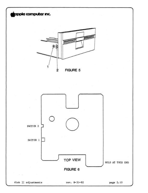
E. WRITE-PROTECT SWITCH ADJUSTMENTIf a customer complains that his system writes over write-protecteddiskettes, or refuses to write on non-protected diskettes, calling them"write-protected", then his write-protect switch may need adjustment orreplacement. Before you replace it, try to adjust it using thefollowing procedure. You will need: the Disk Alignment Aid diskette;the Disk Alignment Tool (P/N UM 652-0158); an Allen wrench or smallscrewdriver (depending on the drive); and a known good Apple ][ andinterface card.1. Power down. Disconnect the customer's drive from his Apple.2. Remove the cover of the customer's drive.3. Using a known good interface card, connect the customer's drive tothe DRIVE 1 position. (Make sure all the pins are in the properholes).4. Using a known good Apple ][, make sure power is down and theninsert the interface card in slot 6.5. Boot the Disk Alignment Aid diskette and select WRT PROTECT SWITCHfrom the menu. When the drive starts running, remove the diskette.6. The switch is located just inside the front left side of thehousing as you face the drive door. Locate the two setscrewsholding the write-protect switch in place (Figure 5, #1 & 2). Thefar setscrew (Figure 5, #1) forms a pivot for the switch; the nearsetscrew (#2) sets the switch position.7. Holding the Disk Alignment Tool as in figure 6, insert it all theway into the drive and leave the drive door open; then turn thedisk drive upside down.8. Loosen the rear setscrew; then loosen the front setscrew and allowthe switch to rise. The monitor should display the message "SWITCHENABLED."9. Press down on the front setscrew (#2) until the monitor displaysthe message "SWITCH DISABLED", and then tighten it.10. Tighten rear setscrew (#1).11. Turn the drive right side up and check the adjustment bywithdrawing the Alignment Tool to the switch 2 position. Theswitch should be enabled. Push the Alignment tool all the way in(switch 1 position). The switch should be disabled.12. Verify again, using a diskette with a write-protect tab pinchedthin (this is a worst-case test).If steps 8 and 9 do not produce the correct screen displays, replacethe switch. If the problem still remains, replace the analog card.disk ][ adjustments rev. 8-31-82 page 2.11
- Page 1: DISK ][ TECHNICAL PROCEDURESTABLE O
- Page 5 and 6: A. REMOVING THE DISK DRIVE COVER1.
- Page 7 and 8: B. REPLACING THE DISK DRIVE CABLERe
- Page 9 and 10: C. REPLACING THE ANALOG CARDRemovin
- Page 11 and 12: D. REPLACING THE COLLET HUBRemoving
- Page 13 and 14: Disk ][ Technical ProceduresSection
- Page 15 and 16: A. COLLET HUB ADJUSTMENTIf the disk
- Page 17: B. DRIVE DOOR ADJUSTMENTWhen the di
- Page 20 and 21: D. DRIVE SPEED ADJUSTMENT — THE D
- Page 25: Disk Drive Technical ProceduresSect
- Page 28 and 29: B. AMPLITUDE TESTThe amplitude test
- Page 30 and 31: 13. After the test signal has been
- Page 32 and 33: Disk Safety Check5. Set the oscillo
- Page 34 and 35: 16. Turn the oscilloscope's trigger
- Page 36 and 37: The Test:7. Boot the Calibration (o
- Page 38 and 39: E. HEAD RADIAL ADJUSTMENTThe Head R
- Page 40 and 41: The Test:13. Change the oscilloscop
- Page 42 and 43: ALPS Drive adjustment:23. Adjust th
- Page 44 and 45: F. COMPARATOR OFFSET ADJUSTMENT:The
- Page 46 and 47: 13. After the test signal has been
- Page 49: Disk ][ Technical ProceduresSection
- Page 53: Disk ][ Technical ProceduresSection
- Page 56 and 57: Disk ][ Analog Board rev. Jun 84 Pa
- Page 58 and 59: Disk ][ Analog Board rev. Jun 84 Pa
- Page 60 and 61: Disk ][ Analog Board rev. Jun 84 Pa
- Page 62 and 63: Disk ][ Analog Card rev. Jun 84 Pag
- Page 64 and 65: Disk ][ Analog Card rev. Jun 84 Pag
disk ][ adjustments rev. 8-31-82 page 2.10


