
You also want an ePaper? Increase the reach of your titles
YUMPU automatically turns print PDFs into web optimized ePapers that Google loves.
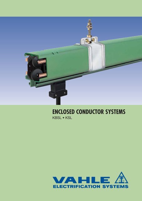
ENCLOSED CONDUCTOR SYSTEMS<strong>KBSL</strong> • <strong>KSL</strong>
POWERAILS <strong>KBSL</strong> – <strong>KSL</strong>INDEX Page PagePowerail versions (Photos) 2 Transfer funnels 14Basic description 2, 3 Anti-condensation section 15Technical data 3 Removing section 16Powerail, Cat.-Nos. and Weights 4, 5 Expansion joint section 17Standard sections and curves 6 Collectors 18Jointing material 7 Double collectors 18Brackets 8 Tow arms 19Hangers 9 Spare parts 19End feeds 10 Examples for ordering 20, 21Line feeds 10, 11 KTW System incl. <strong>KBSL</strong> 22, 23End caps 11 Flexible tow arm configuration 24Conductor dead sections 11 Application photo 24Contact sections, turntables and switches 12 Questionnaire 25, 26Transfer guides, straight 13 Product line 28Transfer guides, oblique 13Powerail versions (drawings see page 5).Type <strong>KBSL</strong> (1)color: greenType <strong>KSL</strong>color: greenGeneralThe Powerail types <strong>KBSL</strong> and <strong>KSL</strong> are totally enclosed,touch-proven conductor systems for safe mobile power feeding of:Overhead Cranes, Monorail Systems, Electric Hoists, AutomatedStorage and Retrieval Systems, Electric Power Tools, Machine Tools,Assembly and Test Lines, Hanger Door Motors, Studio & StationLightingSystems and many other applications.Main characteristics are minimum space requirement, easy installationand resistance against corrosion.<strong>VAHLE</strong> Powerails fully meet all VDE safety requirements.Other combinations of cross sections, as shown on page 5, arepossible. Regulation VDE 0100,part 430 has to be consideredwhen using an N-conductor. Powerail <strong>KSL</strong>T can be equippedwith sealing strip „D“ (IP 24) or with plastic shielding „FP“.Apporovals<strong>KSL</strong>: UL-approved, CSA-approved.Please contact us before ordering.HousingThe compact insulating housing holds from 4-5 pure copperconductors. Suitable for indoor applications.Standard sections are 1, 2, 3 or 4 m long.Other sections and curves are available.Type <strong>KSL</strong> is equipped with stiffener clamps.The ground conductor is identified by international color code. Longand short lip housing profiles (see page 6) and collector safety keysavoid phase reversing.Any number of conductors can be accomplished by installingvarious Powerails side by side.2(1) <strong>KBSL</strong> is w/o stiffener clamps.<strong>KSL</strong> will be equipped with stiffener clamps.
Impedanceat50 Hertz20° CW / 1000 mResistanceat20° CW / 1000 mWeightkg/mOrder-No.Configurations1,81 1,80 1,643 252 96•1,81 1,80 1,643 256 55•1,31 1,28 1,778 253 21•1,31 1,28 1,778 253 25•0,76 0,72 2,134 253 23•0,59 0,53 2,455 252 68•0,38 0,36 3,060 252 69•1,81 1,80 1,734 256 13•1,81 1,80 1,734 256 56•1,31 1,28 1,903 253 22•1,31 1,28 1,903 253 26•0,76 0,72 2,348 253 24•0,59 0,53 2,668 252 70•0,38 0,36 3,274 252 71•<strong>KBSL</strong> 4 pole, 40-200 A color green<strong>KSL</strong> 4 pole, 40-200 A color green(* ) 51,81 1,80 1,753 257 36•1,81 1,80 1,753 257 64•1,31 1,28 1,888 250 00•1,31 1,28 1,888 251 46•0,76 0,72 2,244 250 01•0,59 0,53 2,565 250 69•0,38 0,36 3,170 254 04•1,81 1,80 1,844 256 93•1,81 1,80 1,844 257 65•1,31 1,28 2,013 250 02•1,31 1,28 2,013 251 47•0,76 0,72 2,458 250 03•0,59 0,53 2,778 250 73•0,38 0,36 3,384 254 05•<strong>KBSL</strong> 5 pole, 40-200 A color green<strong>KSL</strong> 5 pole, 40-200 A color green• Add last number (1, 2, 3, 4 length suffix)in accordance to bars requred.Description in brackets for control.(* ) In case of using a conductor as N.
STANDARD SECTIONS, CURVESSections max. 4 m (1) standardStiffener clampA<strong>KBSL</strong><strong>KSL</strong><strong>KBSL</strong> without stiffener clamps.50<strong>KSL</strong> short with lip stiffener clamps.Sections for plug-in joints and bolted joints are equal.<strong>KBSL</strong><strong>KSL</strong>short lipBABleft Pic. shows 4000 mm standard section, view on short lip side rightExtra finish of <strong>KBSL</strong> and <strong>KSL</strong> surcharge Cat.-No.:Index K Index I (60 A)Type stainless steel copper conductorsclamps & hardwarewith stainless steel cap4-pole 5-pole 4-pole 5-pole<strong>KSL</strong> 250 830 258 301 258 302Index K:Index I: }for special environmental conditionsCurves (2)Production corresponding to customer drawingContact surfaceof the collectorlong lipL1(2)L2(1)L3(4)<strong>KSL</strong>e.g. 4 poles(3)VRU VROSupport spacing750 up to max. 2000 mm,depending on the radiusmax. L = 3600 mm,max. >) 120°HR forLLAHR for LLIMinimum bending radius vertical for<strong>KSL</strong> = 1800 mmMin. bending radius horizontal in mm<strong>KSL</strong>60 A 100 A 140 A 200 A4-pole 600 600 900 9005-pole 750 750 900 900Surcharge 4-polefor bendingOrder-No. <strong>KSL</strong>horizontal curve 251 500vertical curve 251 490Surcharge 5-polefor bendingOrder-No. <strong>KSL</strong>horizontal curve 259 424vertical curve 259 4266(1) Shorter sections see page 4. and 5.(2) Long lip side of Powerails should always be mounted facing the track (see page 8).Notify exceptions for replacements and/or extensions and determine correct curves.
BRACKETS <strong>KBSL</strong> • <strong>KSL</strong>These brackets are easily bolted to any type of standard -beam.View without -beamClaw suitablefor D = 6-15 mmPowerail Type<strong>KBSL</strong> – <strong>KSL</strong>Collector SKR SKN SKNTDim. a 161 + 7 165 +7 175 +7-15 -15 -15For <strong>KBSL</strong> and <strong>KSL</strong> dimensions "a" also for double collectors.View without-beamClaw suitablefor D = 15-25 mmEHK small claw versionDplease declare measure DØ 11small clawAttention:Make sure that hoist wheels have enough clearance. Usesmall claw if necessary. Check -beam dimension D.rail of EHK is identical to type S 1, Cat. 8a.Ø 9Order-No. Order-No.Type X L B max Weight for std.- with smallmm mm mm kg brackets clawEHK 250 250 350 170 1,070 251 600 251 720EHK 300 300 400 170 1,150 251 610 251 730EHK 400 400 500 170 1,300 251 620 251 740EHK 500 500 600 170 1,450 251 630 251 750EHK 600 600 700 170 1,600 251 640 251 760EHK 700 700 800 170 1,750 251 650 251 770EHK 750 750 850 170 1,820 251 660 251 780EHK 800 800 900 170 1,900 251 670 251 790Select next larger size bracket when I-beam dimension B isbetween 170 mm and 300 mm.8(1)Max. width at joint caps with <strong>KSL</strong>, see page 7.
SLIDING HANGERS, FIXPOINT HANGERSSliding hangerM8max. 35(2)1456630for <strong>KBSL</strong> only (one-piece bracket)Sliding hangermounted to Powerail-section.for <strong>KBSL</strong> & <strong>KSL</strong>Sliding hangermounted to Powerail-section.Type Weight kg Order-No.KGB 0,225 259 001Typ Weight kg Order-No.KSH 0,251 252 894KSH/K (1) 0,220 250 660Fixpoint hanger75Fixpoint hanger mounted to Powerail section.Hanger consists of steel clamp and bolt M 8.for <strong>KBSL</strong> & <strong>KSL</strong>Typ Weight kg Order-No.KF 0,215 258 806KF/K (1) 0,215 258 807(1)stainless steel(2)Flat washers only be used in slotted holes.9
FEEDSEnd feedswithout powerail sectionEnd feed comes loose without Powerail. It will be mounted ateither end.for <strong>KBSL</strong> & <strong>KSL</strong>Cable gland M 32,Cable-Ø 17 - 26 mmfor cable cross section max. 10 mm 2Weight Order-No. Order-No.Type (2) A kg Power line Control lineHS c/w PE SS w/o PEKEK 4/40-60 40-60 0,400 258 421 258 423KEK 5/40-60 40-60 0,420 258 422 258 424Line feeds (1)with 2 m cables incl. 1 m sectionA Cable-Ø Cable crossmm section mm 240 9,5 660 11,5 10100 13,5 25140 14,5 35for <strong>KBSL</strong> & <strong>KSL</strong>Terminal box32 mm over PowerailWeight Order-No. Order-No.Type (2) A kg Power line Control lineHS c/w PE SS w/o PEKNKL 4/ 40 40 4,000 259 209 259 205KNKL 4/ 60 60 4,100 259 211 259 207KNKL 4/100 100 6,300 259 213 –KNKL 4/140 140 8,200 259 215 –KNKL 5/ 40 40 4,400 259 221 259 217KNKL 5/ 60 60 4,700 259 223 259 219KNKL 5/100 100 7,400 259 225 –KNKL 5/140 140 9,950 259 227 –Joint feedM 40 (Ø 19 - 28)The joint feed KNS is without powerail.It can only be used with <strong>KBSL</strong> and <strong>KSL</strong> 4 poleby customerWeight Order-No. Order-No.Type (2) A kg Power line Control lineHS c/w PE SS w/o PEKNS 4/40-60 40-60 0,560 258 001 258 00210(1)The powerail section is part of the system length (see example of ordering page 20 & 21).(2)For full type designation add suffix of Powerail section, e.g. KEK 4/60 w/ PE KEK 4/60 HS Order-No. 258 421.
FEEDS, END CAPS, CONDUCTOR DEAD SECTIONSLine feed (1)with terminal box incl. 1 m powerail sectionCable connections type HSNom.-A M Cable-Ø connection- Cable connection atmmdia.mm 240 25 9 - 18 6 M8 (Type KNK: M6)60 32 17 - 26 10 M8 (Type KNK: M6)100 50 23 - 34 25 M8140 50 23 - 34 35 M8200 50 29 - 40 50 M10All SS-types with PG 25KNK KNKS KNKS40-60 A 40-140 A 200 Aa 115 156 206b 115 196 286c 70 100 140for <strong>KBSL</strong> & <strong>KSL</strong>Weight Order-No. Order-No.Type (2) A kg Power line Control lineHS c/w PESS w/o PEKNK 4/ 40 40 2,464 258 254 258 256KNK 4/ 60 60 2,600 258 258 258 260KNK 5/ 40 40 2,631 258 262 258 264KNK 5/ 60 60 2,800 258 250 258 252KNKS 4/ 40 40 3,314 258 266 –KNKS 4/ 60 60 3,450 258 268 –KNKS 4/100 100 3,800 258 270 –KNKS 4/140 140 4,100 258 272 –KNKS 4/200 200 5,400 258 612 –KNKS 5/ 40 40 3,581 258 274 –KNKS 5/ 60 60 3,750 258 276 –KNKS 5/100 100 4,150 258 278 –KNKS 5/140 140 4,450 258 280 –KNKS 5/200 200 5,800 258 616 –End capsConductor dead sectionswith insul.sectionwithout insul.sectionEnd cap assembled on PowerailIt is to be indicated, which copper rails are to be separated andwhich type of current collector is used (see page 5).Installation factory-assembled.for <strong>KBSL</strong> & <strong>KSL</strong>for <strong>KBSL</strong> & <strong>KSL</strong>Type Weight kg Order-No.MEK 0,086 256 527with air gapwith insul.Type 5 mm Type section 30 mmOrder-No.Order-No.STLA 1 251 860 STLI 1 250 220STLA 2 251 870 STLI 2 250 590STLA 3 251 880 STLI 3 250 600STLA 4 251 890 STLI 4 250 610STLA 5 251 900 STLI 5 250 620(1)Above sections come factory assembled on a 1 m Powerail section (Please refer to ordering example on page 20).(2)Suffix types e.g.. KNK 4/60 w/ PE KNK 4/60 HS Order-No. 258 258.11
RCONTACT SECTIONS, TURNTABLES AND SWITCHESContact section (1)w/o cond. (1)Contact area(1)w/o cond.Line feed Powerail TrackTransfer funnelw/o cond.(1)Contact area(1)w/o cond.TurntableTransfer guide oblique cutTurntable frameTrackbaLine feedmax. 20 mmPowerailSliding switchTransfer guideTransfer guideaLine feedamax. 20 mm gapTrackTransfer guide oblique cutMax. 20 mm air gap betweentransfer guides.Switch framePowerailPlease submit drawings oftransfer applications. Specifydimensions a, b, c, Rand angle ( = max. 50° )αcPlease submit drawings for all transfer applications.12(1)Contact sections must not be activated before collectors are fully engaged.
TRANSFER GUIDESfor turntables, switches and spurlinesTransfer guides straightLeft hand versionincl. fixpoint hangerRight hand versionincl. fixpoint hanger105 ± 10The support plate grabs in oblique rivets (45°),50 mm from the leading edge,each 4 mm wide, 2 mm deep.The support plate grabs in oblique rivets (45°),50 mm from the leading edge,each 4 mm wide, 2 mm deep.105 ± 10BBAAshort lip<strong>KBSL</strong><strong>KSL</strong><strong>KBSL</strong><strong>KSL</strong>short lip90110w/o cond.180110w/o cond.1809070 mm overlapping powerail70 mm overlapping powerail4- & 5-poles, 40 to 200 A Sketch shows left hand version (page 6)with Powerail sectionStaggered arrangement of the transferguides to each other:horizontal max. 8 mm, vertical max. 3 mm4- & 5-poles, 40 to 200 A Sketch shows right hand version (page 6)with Powerail sectionStaggered arrangement of the transferguides to each other:horizontal max. 8 mm, vertical max. 3 mmfor <strong>KBSL</strong> & <strong>KSL</strong>Type Weight kg Order-No.AUN 0,340 257 455Transfer guides obliqueLeft hand versionincl. fixpoint hangerRight hand versionincl. fixpoint hanger135 ± 10The support plate grabs in oblique rivets (45°),50 mm from the leading edge,each 4 mm wide, 2 mm deep.The support plate grabs in oblique rivets (45°),50 mm from the leading edge,each 4 mm wide, 2 mm deep.135 ± 10BBAA140w/o cond.21070 mm overlapping powerailshort lip<strong>KBSL</strong><strong>KSL</strong><strong>KBSL</strong><strong>KSL</strong>short lip180140w/o cond.21070 mm overlapping powerail4- & 5-poles, 40 to 200 A Sketch shows left hand version (page 6)with Powerail sectionStaggered arrangement of the transferguides to each other:horizontal max. 8 mm, vertical max. 3 mm4- & 5-poles, 40 to 200 A Sketch shows right hand version (page 6)with Powerail sectionStaggered arrangement of the transferguides to each other:horizontal max. 8 mm, vertical max. 3 mmfor <strong>KBSL</strong> & <strong>KSL</strong>Typ Gewicht kg Bestell-Nr.AUNS 0,380 257 459(1)With <strong>KBSL</strong> and <strong>KSL</strong> left and right execution, as well as control line are identically constructed.Always use double collectors or two collectors for transfer applications (see page 18 and 19).13
TRANSFER FUNNELS (1)Left hand versionOffset:horizontal max. 15 mmvertical max. 10 mmRight hand version165 ± 10BBAA165 ± 10short lip<strong>KBSL</strong><strong>KSL</strong>short lip<strong>KBSL</strong><strong>KSL</strong>115247w/o cond.290247w/o cond.290115for <strong>KBSL</strong> & <strong>KSL</strong>Weight Order-No. Order-No.Type kg Power line Control lineHS c/w PE SS w/o PEESTN 4 L 0,795 256 164 256 166ESTN 5 L 0,800 256 172 256 174for <strong>KBSL</strong> & <strong>KSL</strong>Weight Order-No. Order-No.Type kg Power line Control lineHS c/w PE SS w/o PEESTN 4 R 0,795 256 163 256 165ESTN 5 R 0,800 256 171 256 173Flexible support tow arms KFMLN are essential (see page 19).System pictureFixpoint hangerEnd feedJoint coverSliding hangerStiffener clampCollectorStiffener clampEnd cap14(1)Funnels must not be activated before collectors are fully engaged.Suffix types e.g. ESTN 4 L with earth - > ESTN 4 L ref.no. 256 164.
ANTI-CONDENSATION SECTIONS (1)incl. 1 m sectionThis anti-condensation-section consists of 1 m Powerail withopenings covered by a protection hood. The anti-condensation sectiondoes not disconnect the powerail electrically.FeedingNo extra feeds required as the Powerail is not interrupted.CollectorsNo extra collectors required.Application of Anti-Condensation Section:The anti-condensation section will be used where Powerails arepassing from indoor to outdoor, preventing condensation of theoutside mounted Powerail. The warm air from indoors can escapethrough the anti condensation section.InstallationThe anti-condensation section is to be placed directly (0,5 m - 1 mmax.) at the transfer point from heated to unheated part of thefactory floor. See sketch.End capAnti-condensationsection Line feed PowerailFixpoint hangerCrane runway(2) (2)unheatedheatedunheatedfor <strong>KBSL</strong> and <strong>KSL</strong>Order-No.Order-No.Typ (3) Power line Control lineHS c/w PESS w/o PEBTK 4/ 40 257 679 257 681BTK 4/ 60 258 652 258 725BTK 4/100 258 653 –BTK 4/140 258 654 –BTK 4/200 258 655 –BTK 5/ 40 257 680 257 682BTK 5/ 60 258 656 258 726BTK 5/100 258 657 –BTK 5/140 258 658 –BTK 5/200 258 659 –(1)Above sections come ready assembled on 1 m Powerail and are a part of the system length.(2)For longer runs use Expansion joint section (see page 17).(3)Suffix types e.g. BTK 4/60 w/ PE BTK 4 /60 HS Order-No. 258 65215
REMOVING SECTIONS (1)incl. 1 m sectionAAAssembly and disassembly of the collector is possible at the end of the track as well as at the removing section.With plants with frequent maintenance procedures or several current collectors in a system (e.g. test plants)removing sections are to be planned.For single collectorsA-Aclosed80A-AopenTo open the section loosen 4 cross-headscrews and push both sliders outwards.<strong>KBSL</strong> / <strong>KSL</strong>Order-No.Type (2)Power lineHS c/w PEATK 4/ 40 257 988ATK 4/ 60 252 811ATK 4/100 252 812ATK 4/140 252 813ATK 4/200 252 814ATK 5/ 40 257 990ATK 5/ 60 252 816ATK 5/100 252 817ATK 5/140 252 818ATK 5/200 252 819Order-No.Typ (2)Control line.SS w/o PEATK 4/ 40 257 989ATK 4/ 60 252 815ATK 5/ 40 257 991ATK 5/ 60 252 820For double collectors112Mounting and Demountingof the collectorBy opening and closing the sliders at the bottom of the powerailhousing the collector can be mounted and demounted easily.Before opening disconnect mains.The removing section does not disconnect the powerail electrically.<strong>KBSL</strong> / <strong>KSL</strong>Order-No.Typ (2)Power lineHS c/w PEATKD 4/ 40 257 992ATKD 4/ 60 252 831ATKD 4/100 252 832ATKD 4/140 252 833ATKD 4/200 252 834ATKD 5/ 40 257 994ATKD 5/ 60 252 836ATKD 5/100 252 837ATKD 5/140 252 838ATKD 5/200 252 839Order-No.Typ (2)Control line.SS w/o PEATKD 4/ 40 257 993ATKD 4/ 60 252 835ATKD 5/ 40 257 995ATKD 5/ 60 252 84016(1)Above sections come ready assembled on 1 m Powerail and are a part(2)Suffix types e.g. ATK 4/40 w/ PE ATK 4 /40 HS Order-No. 257 988.
EXPANSION JOINT SECTIONS (1)incl. 1 m sectionExpansion joint sections are required to compensate expansionsand contractions of <strong>KSL</strong> Powerail in varying termperatures withoutinterrupting electrical power.<strong>KBSL</strong> / <strong>KSL</strong>Order-No.Typ (2)Power lineHS c/w PEDVK 4/ 40 257 054DVK 4/ 60 252 430DVK 4/100 252 440DVK 4/140 252 450DVK 4/200 250 249DVK 5/ 40 257 687DVK 5/ 60 252 470DVK 5/100 252 480DVK 5/140 252 490DVK 5/200 250 250Order-No.Typ (2)Control lineSS w/o PEDVK 4/ 40 257 688DVK 4/ 60 252 460DVK 5/ 40 257 689DVK 5/ 60 252 500The expansion joints are used if the powerail length between twocurves, switches or other fix points is exceeding 20 m (10 m at hightemperature fluctuation) , or corresponding to a temperature differencet of.End capFixpointFig. 1Expansionjoint section Line feed Powerail t 20° C = 100 m t 30° C = 68 m t 40° C = 50 m t 60° C = 34 m t 80° C = 25 mTrackmax. lengthFig. 2Adjacent sketches, Fig. 1 and Fig. 2 show this type of application.Longer runs or a higher difference in temperature require severalexpansion joints or the telescope sections. When in doubt pleaseconsult the factory.For arrangements of the fixpoints refer to sketch 1-3.The remaining conductor sections have to be arranged in slidinghangers.FeedingExpansion joints do not interrupt electrical power, so there is noneed for an extra feeding. Expansion joints do not influence the voltagedrop of a system.Fig. 3Current collectorNo special or extra collector required.Extension diagram to the expansion sectionMountingThe expansion joint section is installed on sliding hangers in thecenter between two fix points.The gap dimensions «a» depends on the ambient temperature duringinstallation. See adjacent diagram and example.Example: Temperature18 °C «a» = 50 mm(1)Above sections come ready assembled on 1 m Powerail and are a part of the system length.(2)Suffix types e.g. DVK 4/60 w/ PE DVK 4 /60 HS Order-No. 252 430.17
COLLECTORSSKR, 5-poleSKN, 5-poleType (3)Order-No.Order-No.A (1) Power line Type(3)A(1) Control line PolesHS c/w PEST w/o PE<strong>KBSL</strong> & <strong>KSL</strong>SKR 4/25-1 25 256 773 SKR 4/25-1 25 255 928 4 0,485 100 –SKR 5/25-1 25 257 690 SKR 5/25-1 25 255 931 5 0,572 100 –SKR 4/40-1 40 255 926 – – – – 0,665 100 –SKR 5/40-1 40 255 929 – – – – 0,795 100 –SKN 4/40-1 40 257 130 SKN 4/25-1 25 257 170 4 0,915 180 80SKN 5/40-1 40 257 140 SKN 5/25-1 25 257 180 5 1,045 180 80SKN 4/40 K-1 40 257 150 SKN 4/25 K-1 25 257 190 4 0,885 180 80SKN 5/40 K-1 40 257 160 SKN 5/25 K-1 25 257 200 5 1,035 180 80WeightkgMax.speedm/min.NormalTransferGeneralfor straight runs andcurves R > 0.6 m/withball bearing wheelsNot to be used fortransfer guides and transferfunnelsfor straight runs andcurves R > 1.2 m/withball wearing wheelsfor curved runsR 0.6-1.2 m/withball bearing wheels508 DSKN485 DSKR585 DSKR608 DSKN137 DSKN125 DSKRconnecting bar310500 mm at TKLIllustration shows DSKN, 5-pole, type S180 DSKN170 DSKRIllustration shows DSKR, 5-pole, type Fconnecting strap410F = flexible strap connection for curves (2)S = rigid bar connection for straight runsOrder-No.Type (3) A(1) Power line Type (3) A (1)HS c/w PEOrder-No.Control lineST w/o PE<strong>KBSL</strong>und <strong>KSL</strong>DSKR 4/50 F-1 50 257 691 DSKR 4/50 F-1 50 256 485 4 1,430DSKR 5/50 F-1 50 257 692 DSKR 5/50 F-1 50 256 491 5 1,600DSKR 4/50 S-1 50 257 693 DSKR 4/50 S-1 50 256 371 4 1,210DSKR 5/50 S-1 50 257 694 DSKR 5/50 S-1 50 256 372 5 1,384DSKR 4/80 F-1 80 256 473 – – – 4 1,790DSKR 5/80 F-1 80 256 479 – – – 5 2,050DSKR 4/80 S-1 80 255 944 – – – 4 1,570DSKR 5/80 S-1 80 256 370 – – – 5 1,830DSKN 4/80 F-1 80 257 780 DSKN 4/50 F-1 50 257 880 4 2,230DSKN 5/80 F-1 80 257 790 DSKN 5/50 F-1 50 257 890 5 2,550DSKN 4/80 S-1 80 258 385 DSKN 4/50 S-1 50 258 386 4 1,900DSKN 5/80 S-1 80 258 387 DSKN 5/50 S-1 50 258 388 5 2,200Trolley connecting cable 1 m long. Longer cable available. Copper cross section 2.5 mm 2 per core for 25 Aand 4 mm 2 for 40 A. Longer cable available.Collectors for higher speed and cleaning trolleys on request.PolesWeightkg18(1)All ampere data for 60%intermittent duty. For the Powerail types <strong>KBSL</strong>/<strong>KSL</strong> with CU-Inox conductors consider half of the electrical ampere load.(2)Do not use double collectors, but 2 singles for curves with less than 1,2 m radius and for transfer guides more than 45°oblique cut (see page 12).(3)For full Type designation add Power or Control, suffix e.g. SKR 4/25-1 w/ PE SKR 4/25-1 HS Order-No. 256 773SKR 4/25-1 w/o PE SKR 4/25-1 ST Order-No. 255 928.
TOW ARMS & SPARE PARTSfor single & double collector (2)Mounting dimensions see page 8flexible support type, with single collectorfor transfer funnels (see page 14)Mounting dimensions see page 2430251006025slotted hole9 x 2045slotted hole9 x 183309026543138If you are going to use the flexible towing arm in system withcurves please contact us.Type Weight kg Order-No.KWS 0,480 250 380KWS/K (1) 0,480 252 340Type Weight kg Order-No. for all typesKFMLNfür SKN1,170 259 506Spare partsPowerail Type <strong>KBSL</strong> <strong>KSL</strong>Order-No.Order-No.Joint cap, 150 mm for plug-in joint and bolted joint 257 921 257 921Stiffener clamp, 50 mm – 258 797Stiffener clamp of stainless steel – 258 812Bolted joint splice w/hardware plug in joint, max. 100 A 259 274 259 274Bolted joint 40 - 200 A 258 796 258 796Adapter for new/old style Powerail (for old <strong>KSL</strong>) 258 822 258 822<strong>KBSL</strong> & <strong>KSL</strong>Collector Type SKR SKN(K)Order-No.Order-No.Carbon brush phase, incl. brush holder (lateral) 257 600 254 890Carbon brush upper fifth pole, incl. brush holder 257 600 254 891Carbon brush ground , incl. brush holder (lateral) 257 601 254 892Carbon pressure spring, standard (ca. 5 N) 258 758 258 757Carbon pressure spring, reinforced (ca. 8,5 N) 258 761 258 760Throat part, straigth runs (SKN) – 254 893Throat part, for curves (SKN/K) – 254 894Glider plate – –Trolley wheel (below) – 254 895Guide roller (above) – 254 903Connecting strap for double collectors 258 379 258 379Connecting bar for double colectors 258 430 258 431Attachment clamp KWZL – 254 897Attachment clamp KWZ 250 310 –Cleaning brushes complet set (2 pieces) – 252 851(1) Stainless steel(2) In case of installing 2 Powerail systems in parallel use one towing arm each per collector unit.19
EXAMPLES FOR ORDERINGRunway Electrification – 40 mQty. Description Type Order-No. Type Order-No.9 Powerail, 4 m <strong>KBSL</strong> 4/60-4 HS 253 214 <strong>KSL</strong> 4/60-4 HS 250 0041 Powerail, 3 m <strong>KBSL</strong> 4/60-3 HS 253 213 <strong>KSL</strong> 4/60-3 HS 225 0031 Line Feed, 1 m KNKS 4/60 HS 258 268 KNKS 4/60 HS 258 26810 Joint Kits VBK 4 257 907 VBK 4 257 9072 Fixpoint Hangers KF 258 806 KF 258 80619 Sliding Hangers KGB 259 001 KSH 250 0502 End Caps MEK 256 527 MEK 256 5271 Double Collector DSKN 4/80 S-1 HS 258 385 DSKN 4/80 S-1 HS 258 3851 Tow arm K ⁄ WS 250 380 KWS 250 380Crane Trolley Electrification – 12 mQty. Description Type Order-No. Type Order-No.2 Powerail, 4 m <strong>KBSL</strong> 4/60-4 HS 253 214 <strong>KSL</strong> 4/60-4 HS 250 0041 Powerail, 4 m <strong>KBSL</strong> 4/60-4 HS 253 214 <strong>KSL</strong> 4/60-4 HS 250 004to make up1 x 3,890 m1 End Feed KEK 4/40-60 HS 258 421 KEK 4/40-60 HS 258 4211 Transfer Guide AUN 257 455 AUN 257 4550,110 m long2 Joint Kitsl VBK 4 257 907 VBK 4 257 9071 Fixpoint Hanger KF 258 806 KF 258 8065 Sliding Hangers KGB 259 001 KSH 252 8441 Double collector DSKN 4/80 S-1 HS 258 385 DSKN 4/80 S-1 HS 258 3851 Tow arm KWS 250 380 KWS 250 380Spur Rail Electrification – 30 mXXRunway electrificationQty. Description Type Order-No. Type Order-No.7 Powerail, 4 m <strong>KBSL</strong> 4/60-4 HS 253 214 <strong>KSL</strong> 4/60-4 HS 250 0041 Powerail, 1 m <strong>KBSL</strong> 4/60-1 HS 253 211 <strong>KSL</strong> 4/60-1 HS 250 001to make up1 x 0,890 m1 Line Feed, 1 m KNK 4/60 HS 258 258 KNK 4/60 HS 258 258incl. 1 m Powerail1 Transfer Guide AUN 257 455 AUN 257 4550,110 m lang8 Joint Kits VBK 4 257 907 VBK 4 257 9071 Fixpoint Hanger KF 258 806 KF 258 80614 Sliding Hangers KGB 259 001 KSH 252 8941 End Cap MEK 256 527 MEK 256 527Crane trolleyelectrificationXXSpur rail electrificationX = Fixpoint suspension; rest sliding hangers.20
EXAMPLES FOR ORDERING35,5 m Powerail <strong>KSL</strong> 5/60 consisting of:Qty. Description Type Order-No.End feed45°XR = 2100Expansionjoint sectionPowerailX X3500L = 1648(1) Fixpoint hangerTrack1075according to installation temperaturefrom -10 °C to 35 °C2350°5 Powerail, 4 m <strong>KSL</strong> 5/60-4 HS 250 0241 Powerail, 4 m to make up <strong>KSL</strong> 5/60-4 HS 250 0241 x 3500 mm2 Powerail, 3 m to make up <strong>KSL</strong> 5/60-3 HS 250 0231 x 2610 mm and. 1 x 2500 mm1 Powerail, 2 m for horizontal curve <strong>KSL</strong> 5/60-2 HS 250 02245°, R = 2100 mm, L = 1648 mm, LLA2 Power. 3 m to make up horizontal curve <strong>KSL</strong> 5/60-3 HS 250 0232 x 45°, R = 2700 mm, L = 2121 mm, LLI3 Surcharge for bending, horizontal 251 5001 End Feed KEK 5/40-60 HS 258 4221 Expansion Joint DVK 5/60 HS 252 47011 Joint Kits VBK 5 257 9084 Fixpoint Hangers KF 258 80618 Sliding Hangers KSH 252 8941 End Cap MEK 256 5271 Collector SKN 5/40-1 HS 257 1401 Tow arm KWS 250 38090°End capR = 2700XL = 4242(1)2610Rest of powerailto be installed with sliding hangers21
KTW-SYSTEM WITH <strong>KBSL</strong>Power supply with support rail for moving machinerylike drilling machines, grinders, screw drivers etc. along assemblylines or above work benches in any type of plant.No power cables on the floor to cause accidents and no obstructionto personnel by trailing cables.Containers or baskets carrying bolts and nuts or other hardware forthe assembling work can also be supported from and pushed alongthe carrier rail.GeneralThe KTW-System consists of a galvanized C-track taking thecarrier trolleys or other hook-up elements and the Enclosed Powerailfor power supply.The support carrier is supplied with an attachment plate. Electricalplugs, fuses etc. can be fixed to the plate as per customers`requirements.The carrier is mecanically connected to the collectorby a hinge and moved manually. C-track and Powerail are fixed toa support angle.PowerailTypes <strong>KBSL</strong> (40-200A) are used as power supply with appropriatecollector (max. 40 A).Support railcorresponds to C-track, cat. 8a, page 2, galvanized.Support distancedepends on mecanical stress. The max. support distance is 2 mconsidering a load capacity of 50 kg between hangers. For higherloads the support distance must be reduced correspondingly.Other combinations are possible, refer to cat. 4d (LSV)or 3b (VKL).Engineering Data:Powerail <strong>KBSL</strong>Components for attachment plate:(e.g. plugs and fuses) by others.40 A (100% DF) copper conductor 10 mm 260 A (100% DF) copper conductor 15 mm 2100 A (100% DF) copper conductor 25 mm 2140 A (100% DF) copper conductor 35 mm 2200 A ( 80% DF) copper conductor 50 mm 2Voltage rating:up to 690 VNo. of conductors: 4 & 5Std. sections:4 m and short sectionsSupport distance: variable up to 2 mTemperature resistance: –30 °C/+60 °CCollector rating:40 A & multiple (60% DF)Weight: 1.65 up to 3.35 kg/m (see page 5)C-track S 2Section modulus Wx: 3.1 cm 3Moment of inertia: 6.7 cm 4Material:Galvanized steelStd. sections:6 m and short sectionsSupport distance: variable up to 2 mWeight:2.5 kg/mCarrrier TrolleyCarrying capacity: up to 50 kgWeight:approx. 1.5 kgKTW-Systems withDim a 10±1Please consider dimensions of line feeds (see page 10 & 11)22
KTW-SYSTEM WITH <strong>KBSL</strong>Bill of MaterialKTW Systems with Powerail - HS c/w PEAmpere<strong>KBSL</strong> 4 <strong>KBSL</strong> 5capacity Type (2) Weight Order-No. Type (2) Weight Order-No.A kg/m kg/mKTW-Systems40 KTW 4/ 40 4,926 270 607 KTW 5/ 40 5,050 270 60860 KTW 4/ 60 4,960 270 000 KTW 5/ 60 5,090 270 020100 KTW 4/100 5,350 270 010 KTW 5/100 5,580 270 030140 KTW 4/140 5,640 270 040 KTW 5/140 5,860 270 280200 KTW 4/200 6,240 270 050 KTW 5/200 6,460 270 070End feed40-60 KEK4/40-60 0,400 258 421 KEK 5/40-60 0,400 258 422Line feeds (1)40 KNK 4/ 40 2,464 258 255 KNK 5/ 40 2,631 258 26360 KNK 4/ 60 2,600 258 259 KNK 5/ 60 2,800 258 251100 KNKS 4/100 3,800 258 271 KNKS 5/100 4,150 258 279140 KNKS 4/140 4,100 258 273 KNKS 5/140 4,450 259 130200 KNKS 4/200 5,400 254 080 KNKS 5/200 5,800 254 090Collector SKR with carrier trolley & tow arm40 STW 4/40 2,380 270 080 STW 5/40 2,480 270 10040 STWL 4/40 2,480 270 610 STWL 5/40 2,540 270 611STWL is specially suitable for systems with side pull.Spare Parts ListDescription Type Weight kg/m Order-No. Description Type Weight kg/m Order-No.C-track S 2 2,490 316 634 Fixpoint for C-track (2 pieces) FBS 2 0,380 315 150Joint VS 2 0,680 315 050 Sliding Hanger for C-track ABS 2 0,370 315 140End cap for track K 40 0,009 316 449 Carrier trolley w/attachment plate (short) TW 1,700 270 190Bumper PS 2 0,150 317 000 Carrier trolley w/attachment plate (long) TWL 1,800 270 609Mounting bracket TK 0,350 270 130 Tow arm for STW TMN 0,180 270 313Spare parts list for Powerail <strong>KBSL</strong> see page 20.TWL specially suited for systems with side pull.Example for OrderingTypeOrder-No.100 m KTW-System 4pole KTW 4/100 HS 270 0101 Line Feed 4pole KNKS 4/100 HS 258 27120 Collectors c/w carrier trolleys STW 4/ 40 HS 270 080KTW-System in production lineKTW-System for storage/retrieval installations(1)The Powerail section for the line feed ist part of the system lenght.(2)For full type designation add suffix of powerail section see example for ording.23
FLEXIBLE TOW ARM CONFIGURATIONS198max. horizontal offsetmax. vertical offset15 mm10 mma30Ø 10363903053309 x 18 mmfor attachment670138Flexible tow arm KFML with collector SKN for Collector SKNDim. a (1) 95Powerail for the current supply of a hangar crane.24(1)Adjust standard gauge during installation.
QUESTIONNAIRECompany:Date:Tel:E-Mail:Fax:Internet: (URL)1. Number of powerail installations:2. Type of equipment to be powered:3. Operating voltage:_________Volts, Phases:________, Frequency:______HzThree phase voltage: AC voltage: DC voltage:4. Track length:5. Number of conductors: (Neutral: control: ground: )6. Mounted position of powerail:Powerail pendant, collector cable facing to the bottomPowerail pendant, collector cable lateral payout (1)Support distance m (max. 2 m)Other:7. Number of consumers per system:8. Indoor: Outdoor:9. Other operating conditions (humidity, dust, chemical influence etc.)10. Ambient temperature: °C min. °C max.11. Position and number of feeding points (1) :12. How will the conductor system be arranged? (1)13. Brackets required: yes no c/c distance beam / powerailFlange width of beam14. Position and number of isolating sections (e.g. for maintenance):15. Travel speed: in curves: at transfers:16. Power consumption of the individual consumer loads:(Please consult table on reverse side)17. Max. Voltage drop from the powerail feed point to the consumer considering starting current:3% or % referring to nominal voltageRemarks:(1)For curved tracks, powerail with isolating sections etc., we require sketches to enable us to prepare a quotation. pto!Please copy and fill in the questionnaire.25
QUESTIONNAIRETo the nearest local <strong>VAHLE</strong> agency:Date:Motor dataHoist motorsAuxiliary hoistLong travelCross travelPowerkWCrane 1 Crane 2Nominal current Starting current Type of Power Nominal current Starting current Type ofA cos Motors (1) KWMotors (1)N % ED A cos A A cos N % ED A cos AMotor dataHoist motorsAuxiliary hoistLong travelCross travelPowerkWCrane 3 Crane 4Nominal current Starting current Type of Power Nominal current Starting current Type ofA cos Motors (1) KWMotors (1)N % ED A cos A A cos N % ED A cos AMark with * those motors which can run simultaneously.Mark with those motors which can start up simultaneously.(1) Use: K for squirrel cage motorS for slipring motorF for frequency controlled motorFurther remarks:Signature:26We reserve all rights to make alterations in the interests of further development.
NOTES27
Catalog No. 4a/E 2010MANAGEMENTSYSTEMProducts and Service1 Open conductor systemsOpen conductor systems2 Insulated conductor systemsU 10FABA 100U 15 - U 25 - U 35U 20 - U 30 - U 403 Compact conductor systemsVKS 10VKS - VKL4 Enclosed conductor systems<strong>KBSL</strong> - <strong>KSL</strong>KBHMKLD - MKLF - MKLSLSV - LSVG5 Contactless power supplyContactless power supply (CPS ®)6 Data transmission<strong>VAHLE</strong> Powercom ®Slotted Microwave Guide (SMG)7 Positioning systems<strong>VAHLE</strong> APOS ®8 Festoon systems and cables9 Reels10 OthersCatalog No.1a2a2b2c2d3a3b4a4b4c4d5a6a6b7aFestoon systems for - tracks 8aFestoon systems for flat cables on - tracks8bFestoon systems for round flat cables on - tracks8cFestoon systems for - tracks 8dCables8eSpring operated cable reels9aMotor powered cable reels9bBattery charging systems10aHeavy enclosed conductor systems10bTender10cContact wire10dAssemblies/CommissioningSpare parts/Maintenance service0510• Printed in Germany • 1100121/00 E • DS • 2000 • 5/10certified by DQS according to Din ENISO 9001:2008 OHSAS 18001:2007(Reg. Nr. 003140 QM 08/BSOH)PAUL <strong>VAHLE</strong> GMBH & CO. KG • Westicker Str. 52 • D 59174 KAMEN/GERMANY • TEL. (+49) 23 07/70 40Internet: www.vahle.de • E-Mail: info@vahle.de • FAX (+49) 23 07/70 44 44
Catalog No. 4a/E 2010MANAGEMENTSYSTEMcertified by DQS according to Din ENISO 9001:2008 OHSAS 18001:2007(Reg. Nr. 003140 QM 08/BSOH)Products and Service1 Open conductor systemsOpen conductor systems2 Insulated conductor systemsU 10FABA 100U 15 - U 25 - U 35U 20 - U 30 - U 403 Compact conductor systemsVKS 10VKS - VKL4 Enclosed conductor systems<strong>KBSL</strong> - <strong>KSL</strong> - <strong>KSL</strong>TKBHMKLD - MKLF - MKLSLSV - LSVG5 Contactless power supplyContactless power supply (CPS ® )6 Data transmission<strong>VAHLE</strong> Powercom ®Slotted Microwave Guide (SMG)7 Positioning systems<strong>VAHLE</strong> APOS ®8 Festoon systems and cables9 Reels10 OthersCatalog No.1a2a2b2c2d3a3b4a4b4c4d5a6a6b7aFestoon systems for - tracks 8aFestoon systems for flat cables on - tracks8bFestoon systems for round flat cables on - tracks8cFestoon systems for - tracks 8dCables8eSpring operated cable reels9aMotor powered cable reels9bBattery charging systems10aHeavy enclosed conductor systems10bTender10cContact wire10dAssemblies/CommissioningSpare parts/Maintenance service0510• Printed in Germany • 1100121/00 E • DS • 400 • 5/10POWERAIL LTD.WORKING FOR THE FUTURE WITHPowerail Ltd. High Road, Finchley, London, N12 8PT,Phone 020 8446 0350/1246 • Fax 020 8446 7054E-mail: enquiries@powerailltd.com
Catalog No. 4a/E 2010MANAGEMENTSYSTEMProducts and Service1 Open conductor systemsOpen conductor systems2 Insulated conductor systemsU 10FABA 100U 15 - U 25 - U 35U 20 - U 30 - U 403 Compact conductor systemsVKS 10VKS - VKL4 Enclosed conductor systems<strong>KBSL</strong> - <strong>KSL</strong> - <strong>KSL</strong>TKBHMKLD - MKLF - MKLSLSV - LSVG5 Contactless power supplyContactless power supply (CPS ® )6 Data transmission<strong>VAHLE</strong> Powercom ®Slotted Microwave Guide (SMG)7 Positioning systems<strong>VAHLE</strong> APOS ®8 Festoon systems and cables9 Reels10 OthersCatalog No.1a2a2b2c2d3a3b4a4b4c4d5a6a6b7aFestoon systems for - tracks 8aFestoon systems for flat cables on - tracks8bFestoon systems for round flat cables on - tracks8cFestoon systems for - tracks 8dCables8eSpring operated cable reels9aMotor powered cable reels9bBattery charging systems10aHeavy enclosed conductor systems10bTender10cContact wire10dAssemblies/CommissioningSpare parts/Maintenance service0510• Printed in Germany • 1100121/00 E • DS • 400 • 5/10certified by DQS according to Din ENISO 9001:2008 OHSAS 18001:2007(Reg. Nr. 003140 QM 08/BSOH)<strong>VAHLE</strong> INC. • 1167 Brittmoore • Houston, TX 77043 • Phone 713/465-9796 • Fax 713/465-1851