Download - The ERAU Operational Weather Cafe
Download - The ERAU Operational Weather Cafe
Download - The ERAU Operational Weather Cafe

Create successful ePaper yourself
Turn your PDF publications into a flip-book with our unique Google optimized e-Paper software.
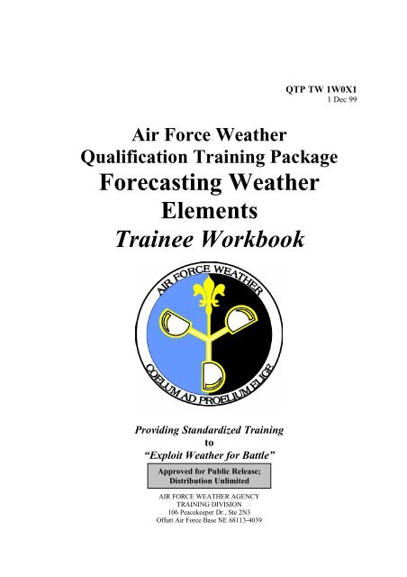
QTP TW 1W0X11 Dec 99Air Force <strong>Weather</strong>Qualification Training PackageForecasting <strong>Weather</strong>ElementsTrainee WorkbookProviding Standardized Trainingto“Exploit <strong>Weather</strong> for Battle”Approved for Public Release;Distribution UnlimitedAIR FORCE WEATHER AGENCYTRAINING DIVISION106 Peacekeeper Dr., Ste 2N3Offutt Air Force Base NE 68113-4039
iiQTP TW 1W0X1
AcknowledgmentsHeadquartersAir Force <strong>Weather</strong> AgencyCommanderCol. Charles W. FrenchDirector, Air & Space ScienceLt. Col. Nathan R. FeldmanAuthorsMSgt Gary Mercer&Mr. Mike JimenezHeadquarters Air Force <strong>Weather</strong> AgencyTechnical Training Branch (DNTT)Editorial StaffSMSgt Michael J. Przybysz&Capt Travis SteenHeadquarters Air Force <strong>Weather</strong> AgencyTechnical Training Branch (DNTT)Address communications to:Forecasting <strong>Weather</strong> ElementsHeadquarters Air Force <strong>Weather</strong> AgencyTraining Division (DNT)106 Peacekeeper Dr, Ste 2N3Offutt AFB, NE 68113-4039PhoneComm (402) 294-2117DSN 271-2117FaxComm (402) 292-8207
QTP TW 1W0X11.7.1. Empirical Rules .......................................................................................... 181.7.2. Locally-Developed ROTs ........................................................................... 191.7.3. Elevation Effects on Wind Speeds .............................................................. 19Module 2 – SKY CONDITIONS .................................................................................. 212.1. General Information .......................................................................................... 232.2. Cloud Formation Ingredients............................................................................. 232.2.1. Condensation Nuclei.................................................................................... 232.2.2. Moisture ..................................................................................................... 232.2.3. Cooling Process.......................................................................................... 232.3. Forecast Aids .................................................................................................... 262.3.1. Climatology................................................................................................ 262.3.2. Extrapolation .............................................................................................. 262.3.3. Forecast Model Guidance ........................................................................... 262.3.4. Using Meteograms...................................................................................... 282.3.5. <strong>Weather</strong> Radar............................................................................................ 322.3.6. Satellite ...................................................................................................... 322.3.7. Local Area Work Chart (LAWC)................................................................ 322.3.8. Skew-T (RAOB) Data ................................................................................ 332.3.9. Upper-Air Charts........................................................................................ 352.4. Forecast Rules of Thumb and Techniques ......................................................... 352.4.1. Rules of Thumb Using Upper Air and Synoptic Features ............................ 352.4.2. Cirrus Forecasting Using Upper Air and Synoptic Features......................... 362.4.3. <strong>The</strong> Gayikian Method of Forecasting Cirrus ............................................... 37Module 3 - VISIBILITY, PRECIPITATION AND OBSTRUCTIONS TO VISION ..... 403.1. Surface Visibility .............................................................................................. 423.2. Hydrometeors - Fog .......................................................................................... 423.2.1. Radiation Fog ............................................................................................. 423.2.2. Advection Fog ............................................................................................ 443.2.3. Upslope Fog ............................................................................................... 443.3.3. Fog Forecasting .......................................................................................... 453.3.1. Forecasting Radiation Fog .......................................................................... 463.3.2. Forecasting Advection Fog ......................................................................... 463.3.3. Fog Dissipation........................................................................................... 46v
QTP TW 1W0X13.4. Hydrometeors - Precipitation............................................................................. 473.5. Precipitation and Frontal Systems...................................................................... 483.5.1. Cold Fronts................................................................................................. 483.5.2. Warm Fronts............................................................................................... 503.5.3. Occluded Fronts.......................................................................................... 523.6. Forecasting Precipitation Type ........................................................................... 543.6.1. Forecasting Precipitation Type Using Freezing Levels................................. 543.6.2. Forecasting Precipitation Type Using Temperatures........................................ 553.6.3. Forecasting Precipitation Type Using Thickness.......................................... 563.6.4. Rain............................................................................................................. 573.6.5. Freezing Precipitation.................................................................................. 573.6.7. Snow ........................................................................................................... 583.6.8. Ice Pellets .................................................................................................... 583.6.9. Mixed Precipitation ..................................................................................... 593.7. Rain Forecasting Rules of Thumb and Techniques ............................................. 603.7.1. Cloud-Top Temperatures............................................................................. 603.7.2. Dew Point Depressions................................................................................ 613.7.3. Radar Signatures Associated with Heavy Rain............................................. 613.7.4. Satellite Signatures ...................................................................................... 613.8. Drizzle Forecasting Rules of Thumb and Techniques ......................................... 623.9. Snow Forecasting Rules of Thumb and Techniques........................................... 623.9.1. General Guidance ....................................................................................... 623.9.2. Forecasting the Location of Heavy Snow Relative to Synoptic Features...... 633.9.3. Vorticity and Heavy Snow Band Width ...................................................... 643.9.4. Determining Snowfall Rates and Accumulation Using <strong>Weather</strong> and Visibility.............................................................................................................................. 643.9.5. Snow Index Using 200 mb Warm Advection (Cook Index)......................... 653.9.6. Using RADAR to Determine Snow Intensities............................................ 663.9.7. Forecasting Snow Begin and End Times ..................................................... 663.9.8. Forecasting Snowfall Amounts Using Numerical Outputs........................... 663.10. Blowing Snow Forecasting Rules of Thumb and Techniques........................... 693.11. Lithometeors - Haze ........................................................................................ 703.11.1. Satellite Indicators .................................................................................... 70vi
QTP TW 1W0X13.11.2. Dissipation of Haze................................................................................... 703.12. Lithometeors - Smoke ..................................................................................... 703.12.1. Dissipation of Smoke................................................................................ 703.13. Lithometeors - Blowing Sand and Dust ........................................................... 713.14. Air Refueling In-Flight Visibility................................................................. 733.14.2. Temperature/Dew Point Depressions ........................................................ 733.14.3. Cloud Thickness ....................................................................................... 743.14.4. Thunderstorm Cirrus................................................................................. 743.15. Whiteout Conditions.................................................................................... 74Module 4 - TEMPERATURES..................................................................................... 764.1. Temperature...................................................................................................... 784.1.1. Insolation and Radiation ............................................................................. 784.1.2. Advection................................................................................................... 794.1.3. Mixing........................................................................................................ 814.2. Maximum Temperature Forecasting .................................................................. 824.2.1. Advection Method ...................................................................................... 824.2.2. Skew-T....................................................................................................... 834.3. Minimum Temperature Forecasting................................................................... 864.3.1. Skew-T....................................................................................................... 864.3.2. Persistence.................................................................................................. 864.3.3. British Method............................................................................................ 864.3.4. Craddock’s Minimum Temperature Method ............................................... 874.3.5. Meteograms................................................................................................ 874.4. Forecasting Temperatures Rules of Thumb........................................................ 894.5. Temperature Indices........................................................................................... 904.5.1. Temperature-Humidity Index (THI)............................................................ 904.5.2. Wet-Bulb Globe Temperature (WGBT) ...................................................... 904.5.2. Heat Index (HI) .......................................................................................... 914.5.3. Heat Stress Index (HSI) .............................................................................. 924.5.4. Wind Chill.................................................................................................. 934.6. Maximum and Minimum Temperatures Using Climatology .............................. 93Module 5- PRESSURE ................................................................................................. 955.1. Air Pressure ...................................................................................................... 97vii
QTP TW 1W0X15.2. Altimeter Setting (ALSTG) ............................................................................... 975.2.1. Possible Altimeter Setting Errors ................................................................ 985.2.2. Altimeter Setting Forecasting Methods ....................................................... 985.3. D-Values........................................................................................................... 995.4. Pressure Altitude (PA)..................................................................................... 1015.5. Density Altitude (DA) ..................................................................................... 1015.6. Sea-Level Pressure (SLP)................................................................................ 102Module 6 - TURBULENCE AND LOW-LEVEL WIND SHEAR .............................. 1056.1. Turbulence Discussion .................................................................................... 1076.2. Turbulence Categories..................................................................................... 1076.3. Turbulence Effects .......................................................................................... 1086.4. Turbulence Types............................................................................................ 1086.4.1. <strong>The</strong>rmal/Convective Turbulence ............................................................... 1086.4.2. Frontal Turbulence ................................................................................... 1086.4.3. Mechanical Turbulence............................................................................. 1096.5. Clear Air Turbulence (CAT)............................................................................ 1106.5.1. Surface Cyclogenesis................................................................................ 1116.5.2. Upper-Level Lows.................................................................................... 1116.5.3. 500 mb CAT Patterns ............................................................................... 1126.5.4. Shear Lines In Upper-Level Lows............................................................. 1136.5.5. Difluent Wind Patterns ............................................................................. 1136.5.6. CAT and Strong Upper Winds .................................................................. 1146.5.7. Confluent Jet ............................................................................................ 1146.6. CAT Associated with Upper <strong>The</strong>rmal Patterns ................................................ 1156.6.1. Temperature Gradients At and Above 300 mb .......................................... 1156.6.2. Open Isotherm Troughs ............................................................................ 1156.6.3. CAT in Cold-Tongue Troughs .................................................................. 1166.6.4. Closed Isothermal Patterns........................................................................ 1166.7. CAT Associated with Troughs and Ridges ...................................................... 1176.7.1. Shearing Troughs...................................................................................... 1176.7.2. Strong Wind Maximum to the Rear of the Upper Trough.......................... 1176.7.3. 500 mb Deep Pressure Trough.................................................................. 1186.8. Jet Stream CAT Model.................................................................................... 120viii
QTP TW 1W0X16.9. CAT Rules of Thumb...................................................................................... 1206.10. Mountain Wave Turbulence .......................................................................... 1216.10.1. Mountain Wave Turbulence Formation................................................... 1216.10.2. Distribution of Clouds and Turbulent Regions in Mountain Wave .......... 1226.11. Low-Level Wind Shear ................................................................................. 1236.11.1. Conditions Favorable for LLWS ............................................................. 1236.11.2. Thunderstorm Gust Fronts ...................................................................... 1236.11.3. Frontal Boundaries.................................................................................. 1256.11.4. Low-Level Jet (LLJ) ............................................................................... 1256.11.5. Gusty Surface Winds .............................................................................. 1266.11.6. Detecting LLWS and Turbulence Using the WSR–88D .......................... 1266.11.7. LLWS Forecasting Rules of Thumb........................................................ 1276.11.8. LLWS Checklist ..................................................................................... 128Module 7 - ICING ...................................................................................................... 1307.1. Aircraft Icing General Information .................................................................. 1327.2. Icing Effects on Aircraft.................................................................................. 1327.3. Icing Types ..................................................................................................... 1347.3.1. Rime......................................................................................................... 1347.3.2. Clear......................................................................................................... 1347.3.3. Frost ......................................................................................................... 1347.4. Icing Intensities............................................................................................... 1357.5. Icing Locations................................................................................................ 1367.5.1. Frontal Systems ........................................................................................ 1367.5.2. Cumuliform Clouds .................................................................................. 1387.5.3. Terrain...................................................................................................... 1387.6. Tools and Techniques in Forecasting Icing...................................................... 1397.6.1. WSR-88D................................................................................................. 1397.6.2. Skew-T..................................................................................................... 1417.6.3. Satellite .................................................................................................... 1437.7. Icing Forecast Rules of Thumb........................................................................ 145MODULE REVIEW QUESTIONS CONFIRMATION KEY ..................................... 149ix
QTP TW 1W0X1TRAINEE WORKBOOK INSTRUCTIONS• This QTP (Qualification Training Package) Trainee Workbook standardizes on-thejobtraining (OJT) for Air Force <strong>Weather</strong> (AFW) personnel. It breaks down subjectmatter by modules into teachable elements called task objectives. A Table ofContents is provided for quick reference to find needed modules.• Workbook material includes a module overview and a list of task objectives requiredfor minimum certification in this subject area. Each workbook module listsequipment and training references, prerequisites and safety considerations, estimatedmodule training time, core training material and review questions, and a modulereview confirmation key.• To facilitate learning and understanding, each QTP has three components: TraineeWorkbook (TW), Trainer’s Guide (TG), and Evaluation Package (EP). <strong>The</strong> TW (thisworkbook) contains all subject matter material and references. <strong>The</strong> TG explains howeach module and task objective is taught. Finally, the EP contains all task certifierwritten exams, performance applications, and confirmation keys to evaluatecomprehension.• Ensure your trainer thoroughly explains all three QTP documents and how tocomplete this training package.• As you progress through each module, answer the review questions pertaining to thatsection. You will find the answers to these section review questions at the end ofeach module. Compare your response to the correct answer.• After completing a module, your trainer will have a task certifier administer theappropriate portion of the EP. This task certifier will grade all responses. Should youscore unsatisfactorily, restudy the module material. Your trainer will provideadditional OJT in weak areas, after which you will retake the evaluation.• After you successfully complete the Evaluation Package for each module, informyour trainer. He will get a task certifier who will perform a final certificationcheckride on the module.• You are ultimately responsible for completing this QTP in the allotted time. If youcannot do so, let your trainer know ahead of time. If you think your trainer isn’tcompetent enough to teach the task objectives or is being unprofessional, then discussthis situation with your supervisor and/or unit training manager. A different trainermay be assigned.• Routine corrections and minor updates to this document will be done via pagechanges. Urgent changes will be disseminated via message. Submit recommendedTW improvements and/or corrections to HQ AFWA/DNT, 106 Peacekeeper Dr., Ste2N3, Offutt AFB, NE 68113-4039.x
MODULE 1 - SURFACE WINDSTRAINEE’S NAME_______________________________CFETP REFERENCE: 14.3.MODULE OVERVIEW:This module covers basic wind principles and procedures, rules, techniques, and rules-ofthumbneeded to aid you in surface wind forecasting.TRAINING OBJECTIVES:• OBJECTIVE 1: Demonstrate that you understand the concepts, the generalrules, techniques, rules of thumb, and principles and procedures concerningforecasting surface winds by answering questions with at least 80% accuracy.• OBJECTIVE 2: Using practical weather data and scenarios, be able todemonstrate your ability to forecast surface winds by computing the correctsolutions and providing answers to questions with at least 80% accuracy.EQUIPMENT AND TRAINING REFERENCES:• AFWA/TN-98/002, Meteorological Techniques• AFMAN 15-124, Meteorological Codes• AFMAN 15-111, Surface <strong>Weather</strong> Observations• AFH 11-203, Volume 1, <strong>Weather</strong> for Aircrews• METOC 50-1P-0002, Volume 5, Introduction to Forecasting: Forecast Chartsand Forecasting <strong>Weather</strong> Elements• Meteorology Today: An Introduction to <strong>Weather</strong>, Climate and the Environment• SC 01W01A, Volume 3, <strong>Weather</strong> Element Forecasting, Flight Hazards, andLimited Data• AWS/TR-79/006 (Revised), <strong>The</strong> Use of the Skew-T, Log P Diagram in Analysisand Forecasting• Aerographer’s Mate 1 & CPREREQUISITES AND SAFETY CONSIDERATIONS:• Familiarity with the TAF code found in Chapter 1, AFMAN 15-124,Meteorological Codes• Familiarity with the sections on winds found in AFMAN 15-111, Surface<strong>Weather</strong> Observations1
QTP TW 1W0X1• Be familiar with interpreting weather features using MetSat imagery• Have a firm grasp on the analysis and prognosis rules and techniques discussed inthe Analysis and Prognosis QTPESTIMATED MODULE TRAINING TIME: 2.5 Hours2
QTP TW 1W0X1Figure 1-2. Coriolis Force1.2.3. Centrifugal and Centripetal ForcesCentrifugal force throws an air parcel outward from the center of rotation (Figure 1-3).Its strength is directionally proportional to the speed and radius of rotation. Centripetalforce, equal in magnitude and opposite in direction to the centrifugal force, attempts tokeep the air parcel moving around a curved path (such as around curved height contourson a constant-pressure surface).1.2.4. Frictional ForceFigure 1-3. Centrifugal and Centripetal ForceAn increase in friction causes a decrease in wind speed and subsequently a reduction inthe Coriolis force (Figure 1-4). Consequently, the weaker Coriolis force no longerbalances the PGF, and the wind blows across the isobars toward lower pressure. It maycause the wind to blow up to 50° across isobars over rugged terrain and 10° acrossisobars over water. <strong>The</strong> effect of frictional force reaches to about 1,500 feet aboveground level (AGL) over smooth terrain and as much as 6,000 feet AGL overmountainous terrain.4
QTP TW 1W0X1Figure 1-4. Frictional Force?1. <strong>The</strong> effect of Coriolis is greatest at the __________ (poles / equator).2. With an increase in friction, the wind velocity __________ (increases / decreases).1.3. Geostrophic Versus Gradient WindsOne of the things you need to understand is the differences between geostrophic andgradient winds, although they are often used interchangeably. Keep in mind that thebiggest difference between the two is that the geostrophic wind is a theoretical whereasthe gradient wind is an actual frictionless wind.1.3.1. Geostrophic WindWhen the flow is purely geostrophic, it is assumed that there is no friction, the isobars arestraight and evenly spaced, and the wind speed is constant. In the real atmosphere,isobars are rarely straight or evenly spaced, and the wind normally changes speed as itflows along. So, the geostrophic wind is usually only an approximation of the “real”wind. However, the approximation is generally close enough to help more clearlyunderstand the behavior of the winds aloft.1.3.2. Gradient WindGradient winds are slightly more complex than geostrophic winds because they includethe action of centripetal force (Figure 1-3). Centripetal force is always directed towardthe center of rotation. Figure 1-5 shows the forces that produce gradient winds aroundhigh and low pressure centers.5
QTP TW 1W0X1Figure 1-5. Gradient Wind (925 mb)Around a low, the gradient wind consists of the pressure gradient force (PGF) andcentripetal force (CE) acting toward the center of rotation, while Coriolis force (CF) actsaway from the center of the low. In a high pressure center, the Coriolis and centripetalforces are directed toward the center of the high, while the pressure gradient force isdirected outward. This wind results from a balance between the pressure gradient forceand the sum of the Coriolis and centripetal forces. It blows parallel to curved isobar. Inthe middle latitudes and tropics, this wind is a better approximation of the actual windspeed than the geostrophic wind speed.• Typically, the gradient level wind is around 2,500 to 3,000 feet AGL.• 925 mb is the level chart most used to estimate the gradient level except inmountainous or high terrain.1.4. Local WindsIn the atmospheric circulation system, small-scale wind systems occur with the generalcirculation pattern. <strong>The</strong>y are a result of the Earth’s rough surface and temperaturedifferences between land and water. <strong>The</strong>se small-scale circulations are frequently calledlocal winds and have names that link them to the place where they occur.<strong>The</strong> absence of a strong pressure gradient is typically necessary for the development ofmost of these often thermally-induced winds. Besides the pressure gradient, surfacetemperatures determine whether the temperature gradient is sufficient to induce suchcirculations as the land/sea breeze, or in the mountain or valley breezes case, whether theinsolation or radiation is sufficient to develop the breeze. With forced circulations likethe fall (glacier) and foehn (chinook) winds, the proper orientation and spacing of theisobars (which is a direct result of pressure gradient) is necessary to develop the winds.1.4.1. Sea (Lake) BreezeA sea breeze occurs during the day when the air over the land becomes warm and rises,creating lower pressure. Since the air over the water is not warmed as rapidly or asmuch, the pressure is higher than over the land. When the pressure gradient is weak, theair flows from the higher pressure to the lower pressure or from sea to land. <strong>The</strong> seabreeze can last up to 2-3 hours after sunset (achieving maximum intensity at maximum6
QTP TW 1W0X1heating). <strong>The</strong>re are lakes around the world that are large enough to create this process(depicted in Figure 1-6). Hence, these winds are called lake breezes.1.4.2. Land BreezeFigure 1-6. Sea Breeze Model<strong>The</strong> land breeze occurs during the night if the land, because of radiation, becomes coolerthan the sea. <strong>The</strong> cooler air over the land produces higher pressure than over the sea.This pressure, combined with the rising air currents over the sea from warmer air, movesthe air from the land to the sea (from high pressure to low pressure). <strong>The</strong> land breeze isnormally weaker (
QTP TW 1W0X11.4.3. Drainage WindA drainage wind occurs at night with strong cooling and a very weak pressure gradient.Due to variations in surface conditions, radiation cools the air in contact with the surfacemore rapidly at some locations than others. Since cooler air is heavier than warmer air, itsinks to lower elevations in sloping terrain. This requires only a very shallow slope andhas been known to occur with slopes less than 200 feet. <strong>The</strong> wind created as the airmoves downslope depends on the steepness of the slope and the amount of cooling. Inthe normal situation for strictly a drainage wind, the velocities rarely exceed 2 to 3 knots.1.4.4. Mountain Breeze<strong>The</strong> mountain breeze, a nighttime feature, is simply a stronger case of the drainage windin mountainous areas. Nighttime radiation cools the air on the side of the mountain fasterthan the air in the valley. As the cooler air becomes denser it sinks toward the lowerelevations and collects in the valleys as depicted in Figure 1-8. Typically, a mountainbreeze may reach speeds of 11 to 13 knots, and the cooler air may extend severalhundreds of feet in depth. In extreme cases, mountain breezes can reach speeds of 50knots.Figure 1-8. Mountain BreezeNecessary factors for mountain breeze (katabatic flow - blowing down an incline)developments are:• Terrain must be greater than 1,000 feet MSL.• Skies must either be clear, or cloudy and rainy with nearly saturated air.• Gradient wind must be less than 11 knots. Gradient winds greater than 11 knotsoverwhelm katabatic flow regardless of wind direction.Areas where katabatic flow is enhanced are:• Leeward slope because of the absence of the gradient wind. Windward slopeshave weak to nonexistent katabatic flow.• Poleward-facing slope because of lesser insolation during the day.• Slopes with extensive cloudiness and precipitation because precipitationevaporation makes the air layer next to the slope neutral to negatively buoyant.8
QTP TW 1W0X1Indications that a mountain breeze has developed are:• Mountain station reports wind direction to be downhill. Valley stations reportwind direction to be down-valley.• Fog and low stratus forms over valley, indicating presence of inversion.1.4.5. Valley Breeze<strong>The</strong> valley breeze is the opposite of the mountain breeze. It occurs during the day whenthe mountain heats faster than the valley. <strong>The</strong> air over the mountainside rises and isreplaced by the air from the valley. This creates a wind up the side of the mountain asdepicted in Figure 1-9 that usually averages about 13 knots. <strong>The</strong> best conditions fordevelopment of these winds are clear skies and weak pressure gradient. With theseconditions, there is nothing to restrict the amount of heating.Figure 1-9. Valley BreezeNecessary factors for valley breeze (anabatic flow - blowing up an incline) developments are:• Terrain must be greater than 1,000 feet above sea level.• <strong>Weather</strong> must be clear to partly cloudy (less than 4/8 cloud cover).• Gradient wind must be less than 11 knots. Gradient winds greater than 11 knotsoverwhelm anabatic flow regardless of wind direction.Mountain regions where anabatic flow is enhanced are:• Windward slopes because gradient wind is forced up the terrain.• Equatorward-facing slopes because of greater insolation.Indications that a valley breeze (anabatic flow) has developed are:• Mountain slope station reports wind direction to be up valley.• Cumulus clouds form over mountain tops and along ridges.9
QTP TW 1W0X11.4.6. Foehn WindA foehn wind is a warm wind that flows down the leeside of mountains, raising thetemperature as much as 50° F in just a few minutes at the base of the mountain. <strong>The</strong>name "foehn" originated in the Alps, and there are several names for this type ofphenomenon in other parts of the world. To name a few, there are the chinook winds(“snow eater”) in the Rockies and the Santa Ana winds in Southern California. <strong>The</strong>formation of this wind depends on warm, moist air rising on the windward side of themountain. As the air rises, it expands and cools, and condensation (clouds andprecipitation) occurs. When the air continues over the mountain top and descends on theleeward slopes, the downslope motion causes compression of the air and resultantadiabatic heating. Because of the compression and heating, the wind accelerates, thusincreasing the heating even more. <strong>The</strong> result is a very strong and very warm wind at thebase of the mountain. Figure 1-10 depicts this process.1.4.7. Fall WindFigure 1-10. Foehn (Chinook) WindTypically the fall (or glacier) wind, a cold wind, originates in snow-covered mountainsunder high pressure. <strong>The</strong> air on the snow-covered mountains is cooled enough so that itremains colder than the valley air despite adiabatic warming upon descent. Near theedges of the mountains, the horizontal pressure gradient force, along with gravity, causesthe cold air to flow across the isobars through gaps and saddles down to lower elevations.This colder, denser air descends rapidly to the valley below. If the wind is channeledthrough a restricted valley, it speeds up and has been known to reach 100 mph for days ata time. <strong>The</strong> temperature in the valley may drop more than 20° F when the breeze sets in.This process is depicted in Figure 1-11. Examples of fall winds are the mistral in thenorthwest Mediterranean (from France), the bora in the Adriatic Sea (from the Balkans),and the Columbia Gorge winds (Columbia River area in northwest CONUS).10
QTP TW 1W0X1Figure 1-11. Fall Wind?3. (TRUE/FALSE) __________ <strong>The</strong> absence of a strong pressure gradient istypically necessary for the development of most local, thermally-induced winds.4. Using the figure below, sketch the expected surface wind flow pattern at 1500L(assuming no strong pressure exists).5. In the figure below, what type of breeze exists at 0700L?a. Sea breeze c. Land breezeb. Valley breeze d. Mountain breeze6. <strong>The</strong> foehn wind is primarily a __________ (warm / cold) wind while the fall wind is a__________ (warm / cold) wind.11
1.5. Wind Forecasting TechniquesQTP TW 1W0X1Accurate wind forecasting is vital to air operations, ground combat operations, and baseresource protection. Techniques and rules-of-thumb have been developed to aid youforecasting surface winds in order to accurately predict the onset, duration, and demise ofthis critical weather element. <strong>The</strong> following information covers non-convective surfacewind forecasting specifically. Convective winds will be fully covered in the Convective<strong>Weather</strong> QTP. Let's begin with the definition of two techniques used for many years:persistence and extrapolation.• Persistence - Persistence, by definition, means a "continued existence oroccurrence." <strong>The</strong> persistence method of forecasting any weather element assumesthat the conditions at the time of the forecast will not change. At most locations,when the synoptic pattern remains relatively unchanged; weather events followdaily cycles.• Extrapolation - Extrapolation commonly refers to the forecasting of weatherpatterns or features based solely on past motions of those features (see Figure 1-12). An awareness of weather-producing systems in the local area, rates ofmovement, and changes in structure is required. Note: Persistence andextrapolation are not confined to wind forecasting, but rather, can be applied tomost any weather element.1.5.1. Frontal WindsFrontal winds are usually forecast by extrapolation of the wind from an upstream stationthat has the same relative position with respect to the front that you anticipate yourstation to have at forecast time. This wind, assuming persistence of frontalcharacteristics, is a close approximation of your station’s wind in the future. UsingFigure 1-12, as the front approaches point B you would expect the southwesterly winds at25 knots occurring at point A to continue east and produce similar winds at point B.Since changes in frontal characteristics affect the wind speeds, an account of them mustbe considered. Deepening or filling of the frontal trough can increase or decrease thewinds, and changes in moisture content increase or decrease the cloud cover.Temperature contrast changes resulting from this or other causes alter wind speeds.Normally, there is less purely diurnal effect along a front than exists deeper within an airmass because diurnal temperature changes along the front are less pronounced. <strong>The</strong>sethings must be considered subjectively, but experience and local studies soon help toweigh these factors effectively in wind forecasting.12
QTP TW 1W0X1Figure 1-12. Frontal Winds Extrapolation1.5.2. Diurnal Temperature DataSurface winds may change as a result of diurnal temperature changes and temperaturechanges associated with the formation or destruction of low-level temperature inversions.Generally when the pressure gradient is weak, the maximum wind speeds occur duringmaximum heating, and the minimum wind speeds occur during maximum cooling.However, short periods of maximum gusts may also occur just as the inversion breaks,which may occur before maximum heating. <strong>The</strong> inversion, once set in the evening, doesnot allow higher wind speeds aloft to mix down to the surface. Winds usually stay lightthroughout the night and early morning until the surface inversion breaks.Knowledge of a low-level inversion "break" time allows you to forecast development ofsurface winds during the day. If surface heating is not sufficient to break the inversion,forecast unchanged wind speeds. To determine inversion break time use a representativesounding:• Step 1: Find the top of the radiation inversion as shown in Figure 1-13.Figure 1-13. Step 113
QTP TW 1W0X1• Step 2: From the inversion top follow a representative isotherm down to thesurface as shown in Figure 1-14.Figure 1-14. Step 2• Step 3: At the surface, determine the temperature that isotherm crosses as shownin Figure 1-15. This temperature represents the surface temperaturecorresponding to the inversion decay.Figure 1-15. Step 3When the inversion breaks, the following rules-of-thumb may be used:• If winds gradually increase above the inversion (and the inversion is below 5,000feet), expect maximum gusts during maximum heating to be 80% of the 5,000-footwind speed.• If winds do not gradually increase above the inversion, forecast 40% to 70% of the5,000-foot wind speed to mix down to the surface.1.5.3. Pressure Gradient Method<strong>The</strong> pressure gradient can provide a reliable estimate of the actual wind in mid-latitudes.Use following steps (Figure 1-16 is an example) to convert an existing surface pressuregradient (millibars) into a representative gradient wind (knots).14
• Step 1: Create a 6°-radius circle with the forecast location at the center.• Step 2: Note pressure value at forecast location.QTP TW 1W0X1• Step 3: Note pressure value at edge of circle in direction system is coming from atright angles to isobars.• Step 4: Find the difference in pressure (millibars) between the forecast locationand the reference point.• Step 5: Use the numerical difference (millibars) found to represent the wind speedin knots (e.g. using Figure 1-14, a 10 millibar difference = 10 knots).• Step 6: <strong>The</strong> gradient wind will be approximately equal to the value derived in Step 5.Now, to figure a representative gradient wind.• Use 50% of the gradient wind as a forecast of the mean surface wind speed.• Use 80%-100% of the gradient wind for daytime peak gusts.• Wind direction follows isobars (adjust for friction, back about 15°).Figure 1-16. Pressure Gradient MethodNote: <strong>The</strong> pressure gradient wind speed is inversely proportional to changes in latitudeor air density (e.g., increasing latitude/air density = decreasing wind speed).1.5.4. Geostrophic Wind MethodUsing the geostrophic wind method described below can provide a good estimate ofshort-term surface winds. For best results, use this method in a 90-minute to 2-hourwindow from the valid time. Geostrophic winds are sensitive to changes in the pressurefields and do not work well in areas of strongly curved isobars. Use following steps toconvert the geostrophic wind to estimated surface wind speeds.15
QTP TW 1W0X1• Step 1: Obtain a value of the geostrophic wind at the forecast location (see Figure1-17.)• Step 2: Convert the geostrophic wind speed to mean surface wind speed. Meanwind speed will be about 2/3 of the geostrophic wind speed during daytime periodof maximum mixing (heating). <strong>The</strong> surface wind may not be representative if thegeostrophic wind is less than 15 knots.• Step 3: Adjust the geostrophic wind direction. In the Northern Hemisphere, bysubtracting 10° over ocean areas and up to minus 50° over rugged terrain (thisshould be determined locally).• Step 4: Now, consider the following:• Do not use geostrophic winds with nearby convection.• Use to forecast surface wind speeds after a frontal passage, but not to forecastwind shifts with frontal passage.• Surface winds may differ considerably from the geostrophic wind under ashallow inversion.• Geostrophic winds may overestimate the actual wind when a low-pressurecenter is within 200 miles of the area being evaluated.Using Figure 1-17 for Ellsworth AFB, SD, the geostrophic wind speed is 20 knots from290°. Using the steps, you estimate surface winds at 13 knots and more from the westsouthwest,240°-260° taking moderately rugged terrain into consideration (KRCA is justeast of the Black Hills).Figure 1-17. National <strong>Weather</strong> Service Geostrophic Wind Chart16
QTP TW 1W0X11.6.2. Using Satellite ImageryLow-level cloud patterns from satellite imagery are valuable in forecasting surface winds,especially in data-sparse oceanic areas. Remember, identifying features such as cloudlines, cloud streets, shear lines, arcs, etc., can provide you with wind directions and/orspeeds. Keep in mind that winds at cloud level may not be the same as the surface wind.1.6.3. Using <strong>Weather</strong> RadarVelocity products and the VAD Wind Profile (VWP) can be used to aid in surface windforecasting. Gusty winds when an inversion breaks and wind shifts are just two featuresthat can be determined using weather radar.1.7. Forecasting Winds Rules of ThumbAs with most weather elements, military and civilian weather researchers and regularforecasters like you have developed rules of thumb (ROTs) over the years. <strong>The</strong> locationyou are forecasting for may require minor deviations due to local topography.1.7.1. Empirical RulesHere are a few empirical rules have been developed over the years to aid in surface windforecasting. Of course, local terrain may have a direct impact on any of these rules.• In southwest wind situations, average wind gusts will approximate 70% of themaximum wind observed in low-level wind data.• In southwest wind situations, peak wind gusts can equal the highest wind speedreported in the low-level wind field. This usually occurs around maximum heating.• In west-northwest wind situations, with moderate to strong cold air advection, peakspeeds can exceed the highest value observed in the low-level wind field.• Wind direction generally follows isobars over smooth terrain but may cross isobarsby up to 50% over rough terrain due to friction.• Winds blow night and day with little change under a strong gradient.• Strong winds occur in areas of strong temperature gradients, behind a strong coldfront for example.• Often if the 1000 mb-500 mb thickness lines are parallel to the surface isobars.When the surface isobars are tightly packed, the surface winds will be enhanced.18
QTP TW 1W0X11.7.2. Locally-Developed ROTsYour unit(s) should have locally-developed techniques and rules-of-thumb for yourforecast locations. <strong>The</strong>se techniques and rules should be very specific and may bederived from larger scale techniques/rules tailored to your forecast location. Forexample, the following wind guidance was developed for a weather station in thenorthwestern United States.• If the subsidence inversion is below 3,000, take the parcel up dry adiabaticallyuntil it crosses the temperature curve. Forecast the surface wind speed based on80 % of wind at that altitude.• If the subsidence inversion will be broken and skies will be clear to partly cloudy,forecast the wind speed to be 50% of the 3,000 feet FDUS wind with gusts to80% of the mean 3,000-foot/6,000-foot wind divided by 2.• Example: 3,000-foot wind is 20 knots and 6,000-foot wind is 30 knots. 50%of 20 = 10 knots. 20 + 30 = 50. 50 ÷ 2 = 25 knots; 80% of 25 knots = 20knots. Your wind forecast would then be 10 knots gust 20 knots.• If the subsidence inversion will be broken and skies will remain mostly cloudy orovercast, forecast wind speed at 50% of the 3,000-foot wind (no gusts).1.7.3. Elevation Effects on Wind SpeedsA decrease of pressure and density of the air, and a decrease of friction with elevationcauses wind speeds, on average, to increase about 1 to 2 knots for every 2,000 feet abovesea level. Table 1-1 shows the increase in wind speed with elevation at specifictemperatures.• After making wind forecasts using other methods, adjust wind speeds forelevation using Table 1-1.Table 1-1. Elevation Effects19
QTP TW 1W0X1?7. Using the pressure gradient method, you determined that you had a 20 mb differencebewteen your location and a point upstream, what should be your representative meansurface wind and your expected peak gusts?a. 16 KTS with gusts 20 KTSb. 10 KTS with gusts 16-20 KTSc. 16 KTS with no gustsd. 10 KTS with no gusts8. You looked at the MM5 3,000-foot and 6,000-foot winds progs for 24 hours fromnow. <strong>The</strong> 3,000-foot wind is 180° at 30 knots, and the 6,000-foot wind is 230° at 45knots. What would be your best estimate of your 24-hour surface winds?a. 15 KTS with gusts 30 KTSb. 15 KTS with gusts 36 KTSc. 23 KTS with gusts 30 KTSd. 30 KTS with gusts 36 KTS9. What must be accomplished prior to effectively using model output as an aid in windforecasting?10. __________ (TRUE/FALSE) Since you have a decrease of pressure, density of theair, and a decrease of friction with elevation, you need to decrease about 1 to 2 knots forevery 2,000 feet above sea level.11. __________ (TRUE/FALSE) In west-northwest wind situations, with moderate tostrong cold air advection, peak speeds can exceed the highest value observed in the lowlevelwind field.At this point, your trainer and/or certifier should answer any questions you, the trainee, haveor to clarify any points you are still unclear on. Your trainer and/or certifier should alsoreview local/regional rules-of-thumb and techniques developed in your AOR(s) with you.20
QTP TW 1W0X1MODULE 2 – SKY CONDITIONSTRAINEE’S NAME_______________________________CFETP REFERENCE: 14.3.MODULE OVERVIEW:This module covers basic cloud formation principles and rules-of-thumb/techniquesderived to aid in cloud forecasting.TRAINING OBJECTIVES:• OBJECTIVE 1: Demonstrate that you understand general rules, techniques, rules ofthumb, and principles and procedures concerning sky condition forecasting byproviding correct answers to questions with at least 80% accuracy.• OBJECTIVE 2: Using practical weather data and scenarios, be able todemonstrate your ability to forecast sky conditions by computing the correctsolutions and providing answers to questions with at least 80% accuracy.EQUIPMENT AND TRAINING REFERENCES:• AFWA/TN-98/002, Meteorological Techniques• AFMAN 15-124, Meteorological Codes• AFMAN 15-111, Surface <strong>Weather</strong> Observations• AFH 11-203, Volume 1, <strong>Weather</strong> for Aircrews• METOC 50-1P-0002, Volume 5, Introduction to Forecasting: Forecast Chartsand Forecasting <strong>Weather</strong> Elements• Meteorology Today: An Introduction to <strong>Weather</strong>, Climate and the Environment• SC 01W01A, Volume 3, <strong>Weather</strong> Element Forecasting, Flight Hazards, andLimited Data• AWS/TR-79/006 (Revised), <strong>The</strong> Use of the Skew-T, Log P Diagram in Analysisand Forecasting• Aerographer’s Mate 1 & CPREREQUISITES AND SAFETY CONSIDERATIONS:• Familiarity with the TAF code found in Chapter 1, AFMAN 15-124,Meteorological Codes21
QTP TW 1W0X1• Familiarity with the sections on sky conditions found in AFMAN 15-111, Surface<strong>Weather</strong> Observations• Be familiar with interpreting weather features off MetSat imagery• Have a firm grasp on the analysis and prognosis rules and techniques discussed inthe Analysis and Prognosis QTPESTIMATED MODULE TRAINING TIME: 2.5 Hours22
QTP TW 1W0X1CORE TRAINING MATERIAL AND REVIEW QUESTIONS2.1. General InformationForecasting cloud elements will undoubtedly take up a substantial portion of yourforecast routine. Time must be spent determining cloud characteristics such as height,type, and amount, as well as formation and dissipation times. An understanding of thephysical processes involved in cloud formation is required to correctly forecast cloudevents.2.2. Cloud Formation IngredientsThree ingredients are required before clouds can form: condensation nuclei, moisture,and a cooling process.2.2.1. Condensation NucleiAlthough the atmosphere is chiefly composed of gases and water vapor, the atmospherealso contains significant quantities of particles called condensation nuclei. Condensationnuclei are suspended particles of sea salt, dust, organic matter and smoke. <strong>The</strong> presenceof condensation nuclei is necessary before condensation will occur.2.2.2. MoistureObviously, moisture is needed or clouds would not form regardless of how muchcondensation nuclei is present or how much cooling was applied to the atmosphere.Moisture is supplied to the atmosphere by the process of evaporation. <strong>The</strong> moisture isthen spread horizontally and vertically around the globe by wind currents.2.2.3. Cooling ProcessFinally, cloud formation requires a cooling process. <strong>The</strong> three cooling processes we willdiscuss in this QTP are radiational cooling, convective cooling, and mechanical cooling.2.2.3.1. Radiational Cooling<strong>The</strong> earth heats and cools faster than the surrounding air. At night the earth releases heatacquired during the day via long-wave radiation, thereby cooling rapidly. This long waveradiation does not heat the air, like short wave radiation from incoming solar rays duringthe day, and the air is cooled by contact with the cooler surface. This contact coolinglowers the temperature of the air near the surface causing a surface inversion to form. Ifthe temperature of the air is cooled to its dew point, fog and/or stratus may form.2.2.3.2. Convective Cooling<strong>The</strong> lifting of air through the atmosphere because of surface heating is called convection.If a parcel of air is heated, it rises (the warm air is less dense than the relatively cooler airsurrounding the parcel). As the parcel rises, it expands (due to decreased pressure) andcools until the temperature and dew point are the same (the saturation point). This pointis the beginning of condensation. Convection ceases at the point that the parcel stopsrising. Cumuliform clouds are formed in this way as depicted in Figure 2-1. Cloud basesare at the altitude of saturation (the CCL), and tops are at the point where the temperatureof the surrounding air is the same as, or greater than, the temperature of the parcel of air.23
QTP TW 1W0X1<strong>The</strong> stability of the lifted air determines the type of clouds formed. Generally, convectiveclouds are formed when unstable air is lifted, and stratiform clouds are formed whenstable air is lifted. <strong>The</strong> cloud types change when their environment changes. Forexample, cumulonimbus clouds frequently change to stratocumulus before dissipating.Stratus clouds may change to cumulus clouds in the afternoon, as surface heating inducesinstability.2.2.3.3 Mechanical CoolingFigure 2-1. Convective CoolingMechanical cooling (lifting) can be broken into two separate types, orographic and frontal.Both of these processes are considered mechanical means of cooling resulting in cloudformation.• Orographic - As moist air is lifted over higher terrain (hills or mountains) it beginsto cool and condense into clouds. <strong>The</strong> cloud type depends on the lapse rate (the rateof decrease in temperature with increase in height) of the air. If a weak lapse rateexists, then stratiform type cloudiness will form. If the lapse rate is steep thencumuliform type clouds will form. Orographically-induced clouds show littlemovement, and usually dissipate on the lee side of their source regions as depicted inFigure 2-2.24
QTP TW 1W0X1Figure 2-2. Orographic Lift• Frontal - At a frontal surface, warmer less dense air is forced up the surfaceof a colder air mass as depicted in Figure 2-3. This lifting produces the sameaffect as orographically lifted air. If the airmass is shallow, the air may not belifted high enough for it to reach its saturation point. This is often why littleto no cloudiness is associated with arctic fronts. <strong>The</strong> type of cloud formationdepends on the lapse rate. If the frontal slope is steep, cumuliform clouds willdevelop. If the slope is gradual, the clouds will usually be stratiform.Figure 2-3. Frontal Lift25
QTP TW 1W0X1?1. What are the three ingredients required for cloud formation?2. What are two factors that determine the rate of cloud dissipation of clouds formed byradiational cooling?3. Typically, cloud bases and tops formed by convective cooling can be found at whataltitudes?4. Describe the effect a shallow frontal slope has on cloud formation.2.3. Forecast AidsIncorrect cloud forecasts can cause aircraft diversions, delays in take-off, and missionaborts. It not only can cost valuable time and money, but in extreme cases, can cost lives.Accurate forecasting of clouds depends on the proper evaluation of atmospheric motion,temperature, moisture fields, stability, modification of air masses, distance from moisturesource and topographical influence. Difficulty lies in quantifying the results ofinteractions between these elements and account for local effects. Fortunately, thesedifficulties can be minimized by several means.2.3.1. ClimatologyRecall from the Climatology QTP, climatology guidance is derived from decades of dataand is a time-proven method that works well for forecasting clouds. Sources includeWind Stratified Conditional Climatology (WSCC) Tables and Modeled Ceiling/Visibility(MODCV), among others.2.3.2. ExtrapolationExtrapolation is a very effective technique for short range cloud forecasting. To forecastclouds by heights or type simply advect the clouds downstream. Satellite imagery, radar,or nephanalysis can all be used for extrapolation of clouds.2.3.3. Forecast Model GuidanceRecall from the Forecast Models QTP, model output, both numerical and graphical(Figure 2-4), are objective tools used to forecast weather elements, including clouds. Aswith all models, the information provided is only as good as the model itself.Initialization and verification of the model is required to effectively use its output.26
QTP TW 1W0X1Figure 2-4. MM5 Output - Cloud Forecast27
QTP TW 1W0X12.3.4. Using Meteograms<strong>The</strong> Forecast Models QTP covered the meteogram and how the models worked. In thissection we will look at the weather that may be forecast using these models.2.3.4.1. Cloud Evaluation Using Relative HumidityRecall that Relative Humidity (RH) is used to determine the amount of cloud cover youmay expect. Look at Table 2-1 below. You may compare these RH values to theamounts on the meteogram. You may notice how the MM5 algorithm shows cloudsoutlined. However, you can use interpretation based on the RH value. You may forecastan area of 80% as SCT, 90% should be forecast as BKN or OVC. Below, you see anexample of how to use the meteogram to forecast sky condition. Another use of the RHis to combine values with upper-air temperatures to determine the potential for icing.Icing is covered more in detail.Example: Refer to Figure 2-5 at the 14 Jul 18Z time period (red arrow). Here yousee a 70% area around 2,200 feet MSL. A sky condition of FEW may be the forecastfor this time period.T-Td Spread (°C) Relative Humidity Cloud Amount0-2° 90-100% Overcast2-3° 80-90% Broken variable Scattered3-4° 70-80% Scattered5° 66-70% Few>5°
QTP TW 1W0X1Figure 2-5. RH and Clouds MM5 Meteogram Section2.3.4.2. Dew Point Depression (DPD)DPD is the number of degrees between the temperature and the dew point. You can findthe DPD on the meteogram by looking for the section titled TDD. <strong>The</strong> color filled area isthe DPD and may be used to determine the height of the convective cloud bases (Table 2-2 shows how to determine the height). This particular chart was developed for the centralUS, but may be adjusted to fit your particular station.Figure 2-6. Dew Point Depression Section on MeteogramExample: Many mornings you will be under clear skies but you know that cumuluswill develop later in the day. To decide the height of the bases, find the dew pointdepression. You see at 14 Jul 18Z (red arrow), the temperature is 30° C (85° F) witha dew point of 19° C (66° F) for a DPD of 11C°. <strong>The</strong>n check the table (Table 2-2) tosee that the height the clouds that time is around 4,400 feet.29
QTP TW 1W0X1DPD(Cº)Estimated CumulusHeight (feet)DPD(Cº)Estimated CumulusHeight (feet)0.5 200 1.0 4001.5 600 2.0 8002.5 1,000 3.0 1,2003.5 1,400 4.0 1,6004.5 1,800 5.0 2,0005.5 2,200 6.0 2,4006.5 2,600 7.0 2,8007.5 3,000 8.0 3,2008.5 3,400 9.0 3,6009.5 3,800 10.0 4,00010.5 4,200 11.0 4,40011.5 4,600 12.0 4,80012.5 5,000Table 2-2. Base of Convective Clouds Using SurfaceDew Point Depressions (DPD)30
QTP TW 1W0X1?5. What amount of cloud cover would you forecast for 16 Jul 09Z (red arrow)?a. CLRb. FEW at 700 feetc. SCT at 700 feetd. BKN-OVC at 700 feet6. At what height should developing CU form at 14 Jul 16Z (red arrow)?31
QTP TW 1W0X12.3.5. <strong>Weather</strong> Radar<strong>The</strong> WSR-88D can be used as a short-term forecast aid in determining cloud basecharacteristics. For example, since scatterers are often more prevalent in and near clouds, theVAD Wind Profile (VWP) may be used in estimating the change of cloud bases as cloudlayers approach or recede. <strong>The</strong> root mean square (RMS) error range determines thereliability of the data (scatterers), i.e., the RMS decreases as the amount of scatterersincreases. RMS values of 4 knots or less (green plot) are considered the most reliable. If thewind plot on the VWP is red, the RMS value is often interpreted as a scattered (SCT) deck.Refer to the <strong>Weather</strong> Radar QTP for additional information about the use of the WSR-88D.2.3.6. SatelliteSatellite imagery can be used to determine cloud type, amount, and movement. MetSatimagery is an observation that is more frequent than synoptic reports and provides data inareas lacking conventional data, such as over ocean, mountainous or desert regions.Animated looping allows systems to be put in motion. Cloud movement can be easilyextrapolated with animated satellite imagery.A MetSat image gives a more complete idea of the vertical structure of the atmospherethan one or two products. Low-, mid-, and upper-level clouds and features can be seensimultaneously allowing for determination of their relationship to each other.2.3.7. Local Area Work Chart (LAWC)An LAWC allows a detailed look at potential cloud producing events. <strong>The</strong> following aresome uses of an LAWC (see Figure 2-7. Note: Green area represents regions of steadyprecipitation). Perform a nephanalysis (cloud layer analysis using set cloud ceilingheight thresholds), then combine with an isobaric analysis to show the position ofpressure systems in relation to clouds. Always use satellite imagery to refine your cloudareas since their boundaries often are between reporting stations. Overlaying or loopingnephanalysis charts can give a graphic representation of cloud movement as well asdeteriorating or improving ceilings. Areas of large pressure falls indicate the probabletrack of lows and associated clouds. <strong>The</strong>ir movement is a combination of the systemmovement and the flow around the system. This, of course, assumes no development ordissipation. A streamline analysis on the LAWC can be used to identify areas ofconvergence, indicating possible cloud development or intensification. Areas ofincreased dew points (isodrosotherm analysis) and decreasing clouds may indicatepossible areas for radiational fog development.32
QTP TW 1W0X12.3.8. Skew-T (RAOB) DataFigure 2-7. LAWCData plotted on a Skew T can help determine where cloud bases may form if certainconditions are met. Three levels, the Convective Condensation Level (CCL), LiftedCondensation Level (LCL), and Mixing Condensation Level (MCL) are usually derivedand displayed automatically. However, recall from the Analysis and Prognosis QTP,they can also be manually calculated.• Convective Condensation Level (CCL) - <strong>The</strong> CCL is the height at which aparcel of air, when heated sufficiently from below rises and becomes saturated. Itoften corresponds well to the height of cumulus cloud bases formed due to surfaceheating (convectively).• Lifted Condensation Level (LCL) - <strong>The</strong> LCL is the height at which a parcel ofmoist air becomes saturated when "lifted" dry adiabatically. <strong>The</strong> lifting is broughtabout by air being forced up (lifted over) fronts and orographic (hilly andmountainous) surfaces. This level can be used as an estimate of cloud basescaused by mechanical lifting.• Mixing Condensation Level (MCL) - <strong>The</strong> MCL is the lowest height at whichsaturation may occur if the near surface layer is or will be mixed completely by33
QTP TW 1W0X1wind action. Clouds formed in mixing layers are stratocumulus. Mixing layers,when approaching saturation, progress from clear skies to thin broken to overcastlayers to dense overcast layers. Keep in mind, mixing will not begin to occur inthe air mass unless certain changes occur. If the mixing process is expectedbecause of increasing wind speeds with a frontal passage, an adjustment of thelower dew point and temperature curves is required to reflect the changesexpected with frontal passage. If mixing is expected to occur after a radiationinversion breaks, an adjustment of the temperature curve to approximate the lowleveltemperature at that time is needed. In both cases, an adjustment of thevertical wind profile is required to determine the top of the mixing level.As you can see, several levels on a Skew-T may be used as indicators where cloud basesmay form. In reality, more than one factor can combine to start cloud formation. Afrontal surface moving through the area will provide mechanical lift, but daily heatingmay occur to add convective lift to the process. Increasing winds may add mixing to theprocess. <strong>The</strong>se factors must be taken into consideration when applying the abovetechniques.In theory, you can interpret cloud layers from the radiosonde observation’s (RAOB)temperature and dew point profiles where the sonde penetrated the clouds. In practice,this is sometimes difficult due to the variability of moisture content, advective andconvective modifications, or the timeliness of the data; all have an impact on cloudamounts and coverage estimations. A series of rules for interpreting clouds from aRAOB have been developed.• A cloud base may be indicated where the dew point depression decreases to 5° Cor less. Typically, dew point depressions in clouds at temperatures of 0° C orabove are 1° or 2° C; in clouds with temperatures from –10° to –20° C, typicaldew point depressions run about 4° C.• <strong>The</strong> top of a cloud is usually indicated by an increase in dew point depression(decrease in RH).• <strong>The</strong> cloud cover can be estimated from the dew point depression (see Table 2-1 inSection 2.3.4.2) and relative humidity (RH) using Table 2-3.RH (in %)Expect Cloud Amount (in 8ths)< 65 070 1 to 275 380 4 to 585 6 to 7> 90 8Table 2-3. Cloud Amount Using Relative Humidity34
QTP TW 1W0X1• Interpretation of cloud type from the thickness and altitude of the moist layer. Ifthe moist layer is less than 4,000 feet thick, the cloud is stratus or stratocumulus;over 4,000 feet thick, the cloud is cumuliform.2.3.9. Upper-Air ChartsUpper-air charts can be used to indicate the heights of moisture and clouds as well as dryregions. Movement of clouds may be detected by extrapolation of the upper-level winds.<strong>The</strong> relationship between surface systems and upper level features can give an idea ofexpected cloud types. Keep in mind, upper air charts should not be used as stand-aloneproducts.Figure 2-8. SatelliteLooking at the 850 mb chart in Figure 2-8, low-level moisture over the eastern half of theUnited States is apparent. However, in the southwestern United States and in Mexicowhere data sparse regions exist, incorporation of a corresponding satellite shot may beneeded to identify the low-level moisture.2.4. Forecast Rules of Thumb and TechniquesOver the years, relationships between clouds, upper-air, and other synoptic features havebeen identified through rules of thumb and techniques that we will cover in the section.2.4.1. Rules of Thumb Using Upper Air and Synoptic FeaturesBelow are some rules/techniques based on observed relationships between upper-air (700mb and above) and synoptic weather features.• When the contours at 700 mb are perpendicular to a surface cold front (inactivefront), the band of weather associated with the front is narrow. <strong>The</strong>re may be aband of clouds associated with a squall line ahead of the front.• When the contours at 700 mb are parallel to a cold front (active front), the cloudsand precipitation extend behind the front as far as the wind remains parallel to thefront.35
QTP TW 1W0X1• Few clouds and very little weather are associated with a front if the 1,000-500 mbthickness lines or the 700 mb isotherms are nearly perpendicular to the cold front.• Clouds and weather are most strongly associated with a front when the 1,000-500mb thickness lines or the 700 mb isotherms are parallel to the cold front.• Cloudiness and precipitation may be found (given sufficient vertical motion andmoisture) under cyclonically-curved contours aloft no matter the presence orabsence of surface features.• In a cold air mass, the instability showers and cumuliform clouds occur onlywhere the air is moving in a cyclonically-curved path.• Warm front cloudiness and precipitation occur where the 700 mb wind flow isacross the warm front from the warm side to the cold side and turningcyclonically or moving in a straight line.• <strong>The</strong> 700 mb ridge line approximates the forward limit of pre-warm frontal middleand low-level cloudiness. <strong>The</strong> 500 mb ridge approximates the forward limit ofthe cirrus cloud shield. <strong>The</strong> sharper the anticyclonic turning of the ridge line, themore accurate this rule.• In a warm air mass moving with a component from the south, cloudiness andprecipitation is greatest under cyclonic turning.• Clear skies occur when a current of air is moving from the north in a straight lineor curving anticyclonically, and in a southward component when it is movinganticyclonically.• Cloudiness and precipitation are likely in areas of strong positive vorticityadvection (PVA) and clear skies are likely under areas of strong negative vorticityadvection (NVA).2.4.2. Cirrus Forecasting Using Upper Air and Synoptic FeaturesForecasting cirrus may not always seem operationally significant, but many weatherfeatures, both surface and aloft, have been correlated with cirrus occurrence or formation.<strong>The</strong> following are rules/techniques developed for forecasting cirrus type clouds.• Cirrus can normally be found 300 to 500 miles ahead of a surface warm front. <strong>The</strong>500 mb ridge line ahead of the surface front is usually the forward limit of thecirrus.• When a warm front has precipitation occurring ahead of it, there is a 60 %probability that cirrus is present above the precipitation.• Cirrus observed with a cold front originates from either the cumulonimbus alongand behind the front or from the convergence around an associated upper trough.• <strong>The</strong> probability of cirrus occurrence is greatest when the wind at 300 mb is fromthe southwest or west and least when from the northeast or east.• Extensive cirrostratus follows the passage of the surface ridge line.36
QTP TW 1W0X1• <strong>The</strong> top of the most extensive and thick layers of cirrus is at or within a fewthousand feet of the tropopause height.• <strong>The</strong> thickness of individual cirrus layers is most frequently 800 feet in the middlelatitudes but may range up to 10,000 feet.• Most of the more extensive and dense cirrus is on the high-pressure (equatorward,or south) side of the jet axis.2.4.3. <strong>The</strong> Gayikian Method of Forecasting Cirrus<strong>The</strong> Gayikian Method is a set of rules for forecasting cirrus. According to the method,there are two primary types of cirrus: advective and convective. Advective cirrus appearsto have a relationship to the orientation, wavelength, and amplitude of the jet stream,isotachs, and the wind flow at a level just below the tropopause.2.4.3.1. Advective Cirrus<strong>The</strong> following rules may be used to forecast cirrus from the current analysis and theforecast 200 mb product.• With no change in either wavelength or amplitude, forecast cirrus to exist in thesame area relative to the jet that now exists. Cirrus generally spreads eastward.• With increasing amplitude of the jet but with no change in jet wavelength,forecast cirrus to spread northward and diminish a little in the south, with thecirrus becoming denser.• With decreasing jet amplitude but no change in jet wavelength, forecast the entirecirrus area to decrease and the cirrus to become less dense.• With increasing jet wavelength but no change in jet amplitude, forecast cirrus toextend more east-to-west and less north-to-south, with the cirrus becoming lessdense.• With increasing jet wavelength and amplitude, forecast cirrus to spreadnortheastward with little change in density.• With increasing jet wavelength but decreasing jet amplitude, cirrus tends todecrease and become less dense.• With decreasing jet wavelength and no change in jet amplitude, the cirrus areadecreases in the eastern portion, with no change in the cirrus density.• With decreasing jet wavelength but increasing jet amplitude, the cirrus areadecreases but tends to spread northward with a slight decrease in density.• With decreasing jet wavelength and amplitude, the cirrus area decreases.• If a upper level confluent area is developing, cirrus forms downstream near thepoint of inflection and builds, or forms, both upstream and downstream. Upstreamfrom the point of maximum wind, the cirrus is stable and generally cirrostratus;downstream from the maximum wind it is unstable and generally cirrocumulus.<strong>The</strong> greatest density of the cirrus is at the point of the maximum wind.37
QTP TW 1W0X1• Cirrus begins to dissipate in areas of upper level difluence and the area ofdissipation spreads upstream.• Cirrus rarely exists in the area south of a jet trough, but a secondary area of cirrusmay be present in the low center to the north. <strong>The</strong>re is normally a clear area orband between this area and that to the east of the trough.• Cirrus usually exists in the center and back part of a ridge, south of the jet.• If the wind maximum (jet) crosses contours toward higher heights downstream,cirrus is more likely to exist than if the jet crosses contours toward lower heights.• <strong>The</strong> presence of frontal or thunderstorm activity within the maximum cirrus areamust be considered. <strong>The</strong> usual effect is to thicken the cirrus, lower the base,increase the height of the top, and extend the cirrus area more easterly.• <strong>The</strong> height of the base and top of advective cirrus appears to have a closerelationship to the vertical wind shear. Although no statistical evaluation has beendetermined, cirrus has been noted to be more prevalent with certain types of windprofiles. <strong>The</strong> height of the base and top of the cirrus layer can be determined fromthe following rules:• <strong>The</strong> greater the wind shear between cirrus bases and tops, the greater thedensity, the probability of occurrence, and the validity of this rule.• Cirrus is in layers and of low density with the total distance from the base of thelowest layer to the top of the highest layer being greater when the wind profileshows indistinct layers of maximum wind.• When there is no distinct wind shear in the profile, forecast no cirrus, or verythin layers of cirrus that are not visible from the ground and reduce horizontalflight visibility only a little.2.4.3.2. Convective CirrusFor purely convective cirrus the following rules can be applied:• If straight-line or anticyclonic flow exists (at 300 to 200 mb) over the areadownstream from a thunderstorm area, cirrus may appear the next day andadvance ahead of the ridge line.• If the contours over the area downstream are cyclonically curved, cirrus may ormay not appear. It is more likely to appear if the flow is weak.• Cirrus present due to thunderstorms usually dissipates within six hours followingdissipation of the thunderstorm.• <strong>The</strong>re is no definite technique for finding the heights of convective cirrus, but thebase may coincide with a good wind shift or shear and the top is often near thetropopause.38
QTP TW 1W0X1?7. Using the WSR-88D VAD Wind Profile (VWP) below, what can you infer ishappening between 9,000ft and 11,000ft beginning about 1042Z?8. If the base is between the surface and 10,000 feet, the cloud is __________.a. Stratiformb. Cumuliformc. Both A and Bd. None of the aboveAt this point, your trainer and/or certifier should answer any questions you, the trainee, haveor to clarify any points you are still unclear on. Your trainer and/or certifier should alsoreview local/regional rules-of-thumb and techniques developed in your AOR(s) with you.39
QTP TW 1W0X1MODULE 3 - VISIBILITY, PRECIPITATION ANDOBSTRUCTIONS TO VISIONTRAINEE’S NAME_______________________________CFETP REFERENCE: 14.3.MODULE OVERVIEW:This module discusses forecasting visibility, precipitation and obstructions to visionterminology, concepts and rules. <strong>The</strong> trainee will apply this knowledge toward issuing avisibility, precipitation and obstructions to vision forecast. This module describes theconditions necessary to produce visibility-reducing weather and also discusses severaltechniques used in forecasting visibilityTRAINING OBJECTIVES:• OBJECTIVE 1: Answer questions to demonstrate your comprehension of thegeneral rules, techniques, and principles and procedures of visibility forecastingwith at least 80% accuracy.• OBJECTIVE 2: Demonstrate that you understand the general rules, techniques,and principles and procedures concerning forecasting precipitation by answeringquestions with at least 80% accuracy.• OBJECTIVE 3: Be able to show that you understand the general rules,techniques, principles and procedures of forecasting obstructions to vision byanswering questions with least 80% accuracy.• OBJECTIVE 4: Using either real-time weather data or canned scenarios, be ableto provide solutions and answers to questions concerning forecasts of visibility,any applicable precipitation, and/or any obstruction(s) to vision with at least 80%accuracy.EQUIPMENT AND TRAINING REFERENCES:• AFWA/TN-98/002, Meteorological Techniques• AFMAN 15-124, Meteorological Codes• AFMAN 15-111, Surface <strong>Weather</strong> Observations• AFH 11-203, Volume 1, <strong>Weather</strong> for Aircrews• METOC 50-1P-0002, Volume 5, Introduction to Forecasting: Forecast Chartsand Forecasting <strong>Weather</strong> Elements• Meteorology Today: An Introduction to <strong>Weather</strong>, Climate and the Environment40
QTP TW 1W0X1• SC 01W01A, Volume 3, <strong>Weather</strong> Element Forecasting, Flight Hazards, andLimited Data• AWS/TR-79/006 (Revised), <strong>The</strong> Use of the Skew-T, Log P Diagram in Analysisand Forecasting• Aerographer’s Mate 1 & C• AWS/FM-90/001, New Stability Indices and Fog Forecasting TechniquesPREREQUISITES AND SAFETY CONSIDERATIONS:• Be familiar with interpreting weather features off MetSat imagery• Have a firm grasp on the analysis and prognosis rules and techniques discussed inthe Analysis and Prognosis QTP• Familiarity with the TAF code found in Chapter 1, AFMAN 15-124,Meteorological Codes• Familiarity with the sections on visibility, precipitation and obstructions to visionfound in AFMAN 15-111, Surface <strong>Weather</strong> ObservationsESTIMATED MODULE TRAINING TIME: 2.5 Hours41
QTP TW 1W0X1CORE TRAINING MATERIAL AND REVIEW QUESTIONS3.1. Surface VisibilityAccurately forecasting the exact visibility over the next few hours can be difficult; but whenthat time frame expands to 24 hours or more, accurately forecasting visibility can baffle eventhe most experienced forecaster. Even if the forecaster is confident that fog or any otherobstructions to vision will be present, it is still challenging to predict what the exact visibilitywill be. Climatology provides trends and averages of a variety of weather parameters over along period of time. Use climatology first to identify the prevailing ceiling and visibility for thelocation and time of interest. Even though you may be able to forecast the trend correctly, thedifference between 4800 meters and 2400 meters could be the difference between missionaccomplishment and mission delay.When considering what type of obstruction to vision will hamper visibility, you as a forecastermust determine if it is a lithometeor (dry obstruction) or a hydrometeor (wet obstruction).Hydrometers, which can cause a reduction in surface visibility, fall into one of the followingtwo categories: precipitation or fog. Lithometeor is the general term for particles suspended ina dry atmosphere. <strong>The</strong>se include haze, smoke, dust, sand, and salt. Forecasting lithometeorsand hydrometeors will be discussed in greater detail throughout this module.3.2. Hydrometeors - FogAt most locations, fog is the most common visibility restriction. <strong>The</strong> formation of fog results from airbeing brought to saturation by cooling or adding moisture. Fog and stratus are both products ofcondensation and saturation. As the relative humidity of the air increases, and the visibility decreasesdue the increase of water vapor in the air, the landscape becomes masked with a grayish tint. As therelative humidity gradually approaches l00 %, the condensation particles grow larger, andcondensation begins on the less-active nuclei. At this point, a large fraction of the available nucleihave water condensing onto them, causing the droplets to grow even bigger, until eventually theybecome visible to the naked eye. <strong>The</strong> increasing size and concentration of droplets further restrictsvisibility. <strong>The</strong>re are three fog types: radiation, advection, and upslope fog.3.2.1. Radiation FogRadiation fog can be defined as fog that forms over land when radiation cooling (cooling of theearth’s surface) reduces the air temperature to its saturation temperature (i.e., its dew point).Radiation fog is also known as ground fog or valley fog. This type of fog forms best on clear,cool nights when there is a shallow layer of moist air near the ground with a dryer layer above.As the ground begins to cool during the night, the moist air just above the earth’s surface alsocools. As the ground continues to cool, a surface inversion forms. <strong>The</strong> moist lower layerquickly cools to its dew point temperature, and fogs forms. <strong>The</strong>refore, radiation fogs are mostcommon over land in late fall and winter.42
QTP TW 1W0X1Another factor promoting the formation of radiation fog is a light breeze of less than 5 knots.Although radiation fog forms in calm air, slight air movement brings more of the moist air indirect contact with the cold ground and the transfer of heat occurs more rapidly (mixing). Onthe other hand, a strong breeze prevents radiation fog from forming since it causes a mixing ofthe air near the surface with the drier air above. <strong>The</strong> ingredients of clear skies and light windsare associated with large high-pressure areas (anticyclones). Consequently, during the winter,when a high becomes stagnant over an area, radiation fog may form on many consecutive nightsand generally reduce visibilities lower each night.Because cold, heavy air drains downhill and collects in valley bottoms, we normally seeradiation fog forming in low-lying areas. <strong>The</strong> cold air and high moisture content in river valleysmake them extremely susceptible to radiation fog.Radiation fogs form upward from the ground as the night progresses and are usually deepestaround sunrise. However, fog may occasionally form after sunrise, especially when evaporationand mixing takes place near the surface. This usually occurs after a clear, calm night asradiational cooling brings the air temperature close to the dew point in a rather shallow layerabove the ground. At the surface, the air be comes saturated, forming a thick blanket of dew onthe grass. At daybreak, the sun's rays evaporate the dew, adding water vapor to the air. A lightbreeze then stirs the moist air with the drier air above causing saturation (and, hence, fog) toform in a shallow layer near the ground.Often a shallow fog layer will dissipate or burn off by late morning or afternoon. Of course, thefog does not "burn off"; rather, sunlight penetrates the fog and warms the ground, causing theair temperature in contact with the ground to increase. <strong>The</strong> warm air rises and mixes with thefoggy air above, which increases the temperature of the foggy air. In the slightly warmer air,some of the fog droplets evaporate, allowing more sunlight to reach the ground, which producesmore heating, and soon the fog completely dissipates.Satellite photographs show that a blanket of radiation fog tends to "burn off” around its edgesfirst where the fog is usually thinnest and in contact with the surrounding dry air. Sunlightrapidly warms this region, causing the fog to dissipate as the warmer air mixes in toward thedenser foggy area (see Figure 3-1).43
QTP TW 1W0X1Figure 3-1. Time Lapse of Fog Dissipating Along Edges3.2.2. Advection FogCooling surface air to its saturation point may be accomplished by warm, moist air moving overa cold surface. <strong>The</strong> surface must be sufficiently cooler than the air above so that the transfer ofheat from air to surface will cool the air to its dew point and produce fog. Fog that forms in thismanner is called advection fog.Sea fog is an advection fog that occurs where two ocean currents with different temperaturesflow next to one another. Such is the case in the Atlantic Ocean off the coast of Newfoundland,where the cold southward flowing Labrador Current lies almost parallel to the warm northwardflowingGulf Stream. Warm southerly air moving over the cold water produces fog in thatregion. Frequently that fog occurs on about two out of every three days during summer off theNew England coast. Sea fog is notorious in the northern Gulf of Mexico, areas along portionsof the US Pacific coast, along the west coast of Korea, and northern Japan.Advection fog also forms over land. In winter in the United States, warm, moist air from theGulf of Mexico moves northward over progressively colder and slightly elevated land. As theair cools to its saturation point, a fog forms in the southern and/or central United States.Because the cold ground is often the result of radiational cooling, the fog forming in thismanner is sometimes called advection-radiation fog. During this same time of year, air movingacross the warm Gulf Stream encounters the colder land of the British Isles and produces thethick fogs off the English coast. Similarly, fog forms as maritime air moves over an ice or snowsurface. In extremely cold arctic air, ice crystals form instead of water droplets producing icefog.3.2.3. Upslope FogUpslope fog forms as moist air flows up along an elevated plain, knoll, hill, or mountain.Typically, upslope fog forms during the winter and spring on the eastern side of a mountainchain. As the air moves up the mountain slope it expands and cools, and if sufficiently moist,fog forms. Upslope fog that forms over a large area may last for many days.44
QTP TW 1W0X1?1. Which of the following groups consist of lithometeors only?a. Fog, haze, blowing snow,b. Haze, blowing snow, dust, drizzlec. Smoke, drizzle, sand, fogd. Smoke, haze, dust, sand2. What are the two ways fog usually forms?3. Cooling surface air to its saturation point may be accomplished by warm, moist air movingover a cold surface. What type of fog is being discussed here?a. Advection fogb. Radiation fogc. Upslope fog4. When we discuss fog “burn off,” what is actually happening?3.3.3. Fog Forecasting<strong>The</strong> following parameters and conditions (some developed by JJ George) have to be consideredif you think that fog may reduce visibility:• <strong>The</strong> synoptic situation• Time of the year• State of the earth’s surface• Station climatology• Stability of the lapse rate• Stability for the lowest 50 to 150 mb of the atmosphere• State of the hydrolapse (moist lapse rate) for the lowest 50 to 150 mb of the atmosphere• Temperature• Dew point depression• Amount of cooling• Winds• Wind direction• Wind velocity45
• Trajectory of the air over favorable types of underlying surfaces• Upslope/downslope flow• <strong>The</strong> existence of fog areas the night before• Precipitation areas• Cloud cover3.3.1. Forecasting Radiation FogQTP TW 1W0X1Radiation fog is the most common you should encounter. Here are a few conditions needed:• Clear to partly cloudy skies at night. <strong>The</strong> less clouds, the better chance of fog• Moist ground• Light, but not calm winds (if the winds are calm, expect only surface dew to form)• Suppressed daytime heating (cloudy)• A late afternoon dew point depression of 20° F (12° C) or less• In addition to the above conditions, the following can greatly aid fog formation:• A cooling rain during the day• <strong>The</strong> longer the nighttime the better3.3.2. Forecasting Advection FogHere are a few tips that should be helpful if you think advection fog may affect your location:• Moist air with higher dew points moving with light to moderate velocities over anunderlying surface that becomes progressively colder downwind. This condition willproduce fog over land or water areas.• Maximum frequency of fog formation is seen with light winds (2-8 knots)• Under light wind conditions, fog is relatively shallow and stable. With a surfaceinversion and lesser speeds results in a more shallow layer• Winds in excess of 9-10 knots normally cause turbulent mixing, resulting in stratus.• Cloudy days (keep the high temperature down) and clearing nights (allow maximumradiational cooling).3.3.3. Fog DissipationFog may dissipate due to increased solar radiation. In more commonly used terms, fog “burnsoff” after sunrise due to daytime heating. Other ways that the fog may dissipate due to heatingare:• Advection over a warmer surface.• Adiabatic warming by subsidence (i.e., downslope).• Turbulent mixing of the fog layer with adjacent warmer air aloft.46
QTP TW 1W0X1Fog may also dissipate if the moisture is removed (i.e. the air becomes drier). <strong>The</strong> air maybecome drier due to:• Turbulent transfer of moisture upward.• Turbulent mixing of the fog layer with adjacent drier air.• Condensing out water vapor as rain, dew, or frost.3.3.3.1. Satellite CluesMetSat imagery, as we saw earlier in this module, is a valuable tool in detecting fog dissipation.• Clouds erode from outer edges due to vertical mixing of surrounding warmer, drier air.• Thicker (brighter) portions of clouds dissipate last.• Fog is more persistent when:• Covered by cirrus• Over snow cover or cold water surface• Associated with upslope flow• If a fog patch moves as it dissipates, the upstream edge dissipates faster thandownstream edge.• Visible brightness difference (fog versus clear regions) from digital data or enhancedimage has been used to estimate time of fog dissipation3.4. Hydrometeors - PrecipitationForecasting restrictions to visibility caused by precipitation is a function of precipitation typeand intensity. For precipitation to occur, two basic ingredients are necessary: moisture and amechanism for lifting to expand and cool the air sufficiently to promote condensation. Liftingmechanisms include convection, orographic lifting, and frontal lifting. <strong>The</strong>re are manytechniques and methods available for forecasting precipitation.Although there is no one strict rule of thumb relating the intensity of rain to expected visibility,you may use the following table (see Table 3-1) as a guide to forecast visibility based on theintensity of precipitation, especially snow. <strong>The</strong> table may also be used to estimate drizzle. Anote of caution: <strong>The</strong> table should only be used with one form of precipitation at a particulartime. If more than one form of precipitation is expected or the precipitation is expected to occurwith an obstruction, then you should forecast a lower visibility than the one shown in thefollowing table.47
QTP TW 1W0X1Table 3-1. Precipitation Type and Associated Visibility3.5. Precipitation and Frontal SystemsBefore you get into the precipitation forecast rules of thumb and techniques, you mustunderstand the relationship between precipitation types, intensities, and amounts associated withfrontal systems. Frontal systems do not have the same sequence of weather every time, but inthe “classic” systems covered, you should get a feeling of how to forecast for the different typesof fronts.3.5.1. Cold Fronts<strong>The</strong>re are two types of cold fronts: slow moving or active cold fronts and fast moving orinactive cold fronts. You can quickly identify an active cold front by looking at the upper windflow. <strong>The</strong> upper winds are parallel to the front, as are the isotherms. An inactive cold front willhave the upper winds perpendicular to the front and the isotherms are not parallel, but are at anangle of about 30° to the front, usually crossing the cold front near its junction with theassociated warm front.3.5.1.1. Active Cold FrontsWith the slow moving cold front, there is a general upward motion of warm air along the entirefrontal surface with pronounced lifting along the lower portion (closest to the surface) of thefront. This results in widespread frontal cloudiness and precipitation at and behind the frontcaused by actual frontal lifting. See Figure 3-2.<strong>The</strong> weather associated with the slow moving active cold front is dependent on the stability ofthe warm air mass.• If the warm air is stable, a rather broad zone of altostratus and nimbostratus clouds willbe accompanied by light to moderate rain, drizzle, and/or snow, provided there issufficient moisture available. This type of weather may extend several hundred milesbehind the front.• If the warm air is unstable (or conditionally unstable), thunderstorms, rain and/or snowshowers may develop within the cloudbank and may stretch up to 50 miles behind thesurface front.48
QTP TW 1W0X13.5.1.2. Inactive Cold FrontsFigure 3-2. Active Cold FrontInactive or fast moving cold fronts have a very steep frontal slope. This causes the warm air near thesurface to be forced rapidly upward. At higher levels, air flows rapidly down the surface front andcollides with the rising air near the surface. This causes a relatively narrow but often violent band ofweather ahead of the front. <strong>The</strong> fast moving cold front is considered inactive because the liftingoccurs only along and ahead of the front. See Figure 3-3.If the warm air is moist and unstable, a line of convection develops 50 to 200 miles ahead of and parallelto the surface front. If the surface convergence is strong enough, often a squall line with powerfulthunderstorms, heavy rainshowers and possibly large hail may develop.If the warm air is stable, an overcast layer of altostratus clouds and light, steady precipitationmay extend over a large area ahead of the front. Behind the front, unless the cold air is unstableand descending currents are weak, there are few clouds and little if any precipitation.49
QTP TW 1W0X13.5.2. Warm FrontsFigure 3-3. Inactive Cold FrontSteady precipitation is usually common with overrunning condition and the accompanyingstratified clouds. Intermittent or continuous rain/snow is common as far as 300 miles ahead of awarm front. Surface rain, drizzle and snow are associated with the nimbostratus in the warm airabove the frontal surface and with stratus in the cold air. If the warm air is convectively unstable,showers and thunderstorms may occur in addition to the steady precipitation. <strong>The</strong> amount andtype of precipitation vary with the characteristics of the air masses involved and depending onwhether the front is active or inactive. Figure 3-4 shows the typical precipitation pattern withwarm front.Figure 3-4. Example of Precipitation with a Warm Front50
QTP TW 1W0X1If the winds associated with a warm front increase with height and become perpendicular to thefront, then the front is classified as an active warm front. This active warm front producesstrong overrunning and pronounced prefrontal clouds and precipitation. This overrunning air ismoist and stable and nimbostratus clouds with continuous light to moderate precipitation can beexpected up to 300 miles ahead of the warm front.Figure 3-5. Stable OverrunningWhen the overrunning air is moist and unstable, cumulus and cumulonimbus clouds arefrequently imbedded in the nimbostratus and altostratus clouds producing pockets of strongershowers and thunderstorms around the continuous precipitation. This is called the inactivewarm front.Inactive warm fronts, characterized by broken cirrus and altocumulus clouds are produced by adecrease of winds with heights that are perpendicular to the front. When the overrunning air iswarm and dry, it must be lifted to relatively high altitudes before condensation occurs; thus,forming mid and high clouds.Figure 3-6. Unstable Overrunning51
QTP TW 1W0X13.5.3. Occluded FrontsAn occluded front is the combination of two fronts. <strong>The</strong>y form when a cold front overtakes thewarm front and forces it aloft. <strong>The</strong>re are two types of occlusions, a cold occlusion and a warmocclusion. <strong>The</strong> type of occlusion is determined by the temperature difference between the coldair in advance of the warm front. Listed below is a quick reference table (Table 3-2) in helpingyou identify occlusions.3.5.3.1. Cold OcclusionsTable 3-2. Occlusion Identification TechniquesIn the beginning stages of a cold occlusion, the weather and clouds ahead of the occlusion arevery similar to that of a warm front, but the weather near the surface position of the occludedfront is closer to the weather you would expect with a cold front.As the occlusion matures, the warm air is lifted to greater heights and the warm front andprefrontal clouds disappear. Most of the precipitation occurs just ahead of the occlusion.Clearing behind the occlusion is usually rapid, especially if the occlusion is in the advancedstage. Otherwise, clearing may not occur until after the passage of the warm front aloft. SeeFigure 3-7 for the vertical and horizontal depiction of a cold occlusion.Figure 3-7. Structure of a Cold Occlusion52
3.5.3.2. Warm OcclusionsQTP TW 1W0X1A warm occlusion forms when the air in advance of the warm front is colder than the air to therear of the cold front. When the cold air of the cold front overtakes the warm front, it moves upover this colder air in the form of an upper cold front.Figure 3-8. Structure of a Warm Occlusion<strong>The</strong> weather associated with warm occlusions has the characteristics of both warm and cold fronts.<strong>The</strong> order of clouds ahead of the occlusion is similar to the sequence of clouds ahead of a warmfront. <strong>The</strong> cold front type weather occurs near the top of the upper cold front. If either the warm orcool air that is lifted is moist and unstable, showers ,and sometimes, even thunderstorms maydevelop. <strong>The</strong> intensity of the weather along the upper front decreases the further away from thelocation of the over running fronts.Precipitation types change rapidly in occlusions and are usually most severe during the initialstages. However, when the warm air is lifted to higher and higher altitudes, the precipitationactivity diminishes. When showers and thunderstorms occur, they are found just ahead and withthe upper cold front. Normally, there is clearing weather after passage of the upper front, but this isnot always the case.?5. ___________ (TRUE/FALSE) With a slow moving active cold front, there is a generalupward motion of warm air along the entire frontal surface with pronounced lifting alongthe lower portion (closest to the surface) of the front—resulting in cloudiness andprecipitation at and ahead of the front.6. If the warm air mass associated with a slow moving active cold front is stable, what kind ofprecipitation will accompany the nimbostratus and altostratus?53
QTP TW 1W0X17. In general, what kind of precipitation would you expect with a warm front?8. If winds associated with a front increase with height and becomes perpendicular. What kindof front do you have?a. Active warm frontb. Inactive warm frontc. Both active and inactive warm frontsd. None of the above3.6. Forecasting Precipitation TypeA big challenge for forecasters often is, “Will it rain or will it snow?” This kind of decisionhas a huge impact on operations. Here are a few methods and rules used to forecastprecipitation type.3.6.1. Forecasting Precipitation Type Using Freezing LevelsForecasters often use the freezing level to determine the type of precipitation (see Table 3-3).<strong>The</strong> forecast is based on the assumption that the freezing level must be lower than 1,000 feetabove the surface for most of the precipitation reaching the ground to be snow. However,forecasters must understand the complex thermodynamic changes occurring in the low-levels tocorrectly forecast tricky winter precipitation situations. For example, the freezing level oftenlowers 500 to 1,000 feet during first 11/2 hours after precipitation begins, due to evaporativecooling. When saturation occurs, cooling ceases and freezing levels rise to their original heightswithin 3 hours. With strong warm-air advection, the freezing level rises as much as a fewthousand feet in a 6 to 8-hour period. Table 3-4 shows the probability of snow compared to thefreezing level above the surface.Freezing LevelType>2,000 feet Rain
QTP TW 1W0X1Table 3-4. Probability of Snowfall Based on Height ofFreezing Level3.6.2. Forecasting Precipitation Type Using TemperaturesForecasting the precipitation type by using temperatures is a little more difficult. Table 3-5gives some temperature thresholds that work much of the time. <strong>The</strong> low-level temperatures(surface or 1000 mb and 850 mb) are very important. Some locations have also determinedlocal 925 mb temperature thresholds, but a standard temperature has not been determined as ofthis writing.• If the surface temperatures are below freezing, precipitation will be:• Snow if upper levels indicate snow.• Freezing rain if upper levels indicate rain.Temperature Rain Mixed SnowSurface Temperature >40° F (5° C) 35 to 40° F (2to 4° C)Surface Dew Point >35° F (2° C) 25 to 35° F(-4° to 2° F)
QTP TW 1W0X13.6.3. Forecasting Precipitation Type Using Thickness<strong>The</strong> following rules of thumb for forecasting precipitation type using thickness andtemperatures have been time-tested. Designed mainly for the central US, adjustments have tobe made for different locations differ in different regions, dependent upon latitude and localeffects (elevation, mountains, oceans, etc.). Forecasting the type of precipitation usingthickness is relatively easy if you the thresholds in Table 3-6. <strong>The</strong> low levels (1000-850 mb and1000-700 mb) are very important.• Values listed under threshold should be considered as 50% probability of either rain orsnow.• Values under snow indicate precipitation nearly all snow for lower values.• Definitely forecast snow if upper levels thicknesses indicate snow.• Values under rain indicate precipitation nearly all rain for higher values.Layer Flurries Snow Threshold Rain850-500 mb 4,050 m850-700 mb 1,520 m 1,540 m 1,555 m1000-500 mb 5,240 m 5,360 m 5,400 m 5,490 m1000-700 mb 2,800 m 2,840 m 2,870 m1000-850 mb 1,275 m 1,300 m 1,325 mTable 3-6. Precipitation Type Using Thickness3.6.3.1. Using Skew-T to Identify Potential Precipitation Types<strong>The</strong> following methods use the number of freezing levels to forecast the type of precipitationexpected at the surface. Each one considers the change of state of precipitation from liquid-tosolidor solid-to-liquid as it falls through the atmosphere.• Single Freezing LevelIf the freezing level equals or exceeds 1,200 feet above ground level (AGL), forecastliquid precipitation. If the freezing level is less than or equal to 600 feet AGL, forecastsolid precipitation. If the freezing level is between 600 and 1,200 feet AGL, forecastmixed precipitation.• Multiple Freezing LevelsWhen there are multiple freezing levels, warm layers exist where the temperature is above freezing.<strong>The</strong> thickness of the warm and cold layers affects the precipitation type at the surface. If the warmlayer is greater than 1,200 feet thick and the cold layer (temperatures below freezing) closest to thesurface is less than or equal to 1,500 feet thick, forecast freezing rain. Conversely, if the warm layer isgreater than 1,200 feet thick and the cold layer closest to the surface is greater than or equal to 1,50056
QTP TW 1W0X1feet thick, forecast ice pellets. Finally, if the warm layer is between 600 and 1,200 feet thick, forecastice pellets regardless of the height of the lower freezing level.3.6.4. RainAs mentioned above, if the freezing level closest to the surface is > 1,200 feet AGL, forecastliquid precipitation (single freezing level). You can see that in the figure below, the lowest1,200 feet is in the warm air (above freezing) and any precipitation that falls will be rain.Always keep in mind what we mentioned in the first paragraph, that warm or cold advectionalong with evaporative cooling will affect the height of the freezing level. Many “can’t miss”forecasts were missed because the forecaster didn’t take into account the low-level temperatureadvection. Refer to Figure 3-9 as a sample rain Skew-T sounding.3.6.5. Freezing PrecipitationFigure 3-9. Example Skew-T Indicating RainForecasting freezing precipitation can be one of the most daunting challenges a forecaster willface. <strong>The</strong> “windows of opportunities” are actually quite small for this phenomenon. If thethickness of the warm layer is too deep, all you will get is rain. Too shallow, and all that willfall is frozen precipitation, such as snow or ice pellets. <strong>The</strong> smallest variations in temperature(as little as tenths of degrees) can mean a difference between rain, freezing rain, ice pellets, andsnow.Freezing rain occurs less frequently than other winter weather events and falls in very narrowbands, usually not more than 30 miles wide. It is essential to use the Skew-T when determiningthe vertical temperature profile for use in forecasting freezing precipitation. See Figure 3-10.57
QTP TW 1W0X1Figure 3-10. Example Skew-T Indicating Freezing Rain<strong>The</strong> basic conditions necessary for freezing precipitation to occur are a shallow layer of subfreezingair near the ground with warmer, moist air overriding it (providing the air issufficiently moist to produce steady precipitation). Ideally, freezing precipitation occurs aheadof a warm front, which is moving over a cold (below freezing) surface. This situation usuallyproduces a widespread area of freezing precipitation due to the advection of warm moist airover the frontal boundary.Other notable areas favorable for synoptic scale freezing precipitation are north of a stationaryboundary as moist air overruns an arctic or polar air mass and to the rear of a continentalpolar/arctic cold front wedging in under warmer moist air.3.6.7. SnowA snow Skew-T will look similar to the one in Figure 3-11 below. <strong>The</strong> entire air mass is wellbelow freezing. Any precipitation that falls will fall as frozen precipitation.3.6.8. Ice PelletsFigure 3-11. Example Skew-T Indicating SnowIce pellets must have a deep cold pocket near the surface and a warm pocket aloft between 600-1,200 feet thick. As partially melted snow falls into the cold air, it refreezes into ice pellets.This usually occurs in narrow zones between areas of freezing precipitation and snow.58
QTP TW 1W0X1Figure 3-12. Example Skew-T Indicating Ice Pellets<strong>The</strong> above Skew-T (Figure 3-12) is a little more challenging. At first glance, you may thinkthat it may either be mixed precipitation or freezing rain. However, if you closely examine theheight of the freezing level, you will see that it is approximately 1,500 feet above the groundwith a 1,500-foot warm layer above that. Any snow that falls through this thick (1,500 feet)warm layer will melt into rain drops which in turn will refreeze into ice pellets as it falls throughthe deep cold layer (also 1,500 feet).3.6.9. Mixed Precipitation<strong>The</strong> above Skew-T is an example that shows probable mixed precipitation. This is due to thefact that the freezing level is between 600 and 1,200 feet deep. <strong>The</strong> warm air is not deepenough to cause all the frozen precipitation to melt completely.Figure 3-13. Example Skew-T Showing Mixed Precipitation?9. What is the probability that precipitation will fall as snow if the height of the freezing levelabove the ground is 25 mb?a. 50%b. 60%c. 70%d. 90%59
QTP TW 1W0X110. Your station is located at 35° N. Your surface temperature is 33° F with a dew point of 24° F.Aloft, you have an 850 mb temperature of 1° C, a temperature at 700 mb of –5° C, and a temperatureof –14° C at 500 mb. What kind of precipitation should fall ot your location?a. Rainb. Freezing rainc. Mixed rain and snowd. Ice pelletse. Snow11. __________ (TRUE/FALSE) <strong>The</strong> freezing level should be between 600 and 1,200 feet formixed precipitation.12. What type of precipitation should you forecast with a 1000-500 mb thickness of 5330 meters anda 1000-850 mb thickness of 1275 meters?3.7. Rain Forecasting Rules of Thumb and Techniques<strong>The</strong>re are several tools and techniques that you can use to help determine if you are going to getjust a few drops of rain or a deluge. Many of these tools and techniques are listed inAFWA/TN-98/002, which covers forecasting precipitation. In this QTP we are going to go overa few of the ones that may be used in just about any region.3.7.1. Cloud-Top Temperatures<strong>The</strong> thickness of the cloud layer aloft and the temperatures in the upper-levels of clouds are usuallyclosely related to the type and intensity of precipitation observed at the surface, particularly in themid-latitudes (see Table 3-7). Climatology reveals the following:• In 87% of the cases where drizzle was reported at the surface, the cloud-top temperatureswere colder than –5° C.• In 95% of the cases during continuous rain or snow and in 81% of the cases of intermittentrain or snow, the cloud-top temperatures were colder than –12° C; In 63% of the cases,cloud-top temperatures were colder than –20° C.Table 3-7. Relationship Between Cloud-Top Temperatures andthe Probability of Showery Precipitation60
3.7.2. Dew Point DepressionsQTP TW 1W0X1Dew point depressions of less than or equal to 2° C on the 850 mb and 700 mb forecast productsare a good indication of both overcast skies and potential precipitation, assuming there ispotential for upward vertical motion.3.7.3. Radar Signatures Associated with Heavy RainMonitoring Doppler and conventional weather radars is the best way to detect the potential forheavy rains and flooding. Pay particular attention to the signatures below:• Rapidly growing echoes• Slow-moving echoes• Persistency (long lasting)• Train echoes (echoes that move repeatedly over the same area)• Tropical cyclones• Slow moving lines• Line Echo Wave Patterns (LEWPs)• Converging echoes and lines3.7.4. Satellite SignaturesMetSat imagery is a valuable tool to use in evaluating heavy rainfall potential. Considerforecasting heavy rains when any of the following parameters or signatures occur:• Quasi-stationary thunderstorm systems, those that regenerate, and those that move overthe same area• Rapid horizontal expansion of thunderstorm anvils. Infrared (IR) imagery picks this upbest• Rapid vertical growth of convective clouds• Thunderstorm tops colder than –62° C• Overshooting tops• Merging of convective cloud lines and thunderstorms• Mesoscale Convective Complexes (MCCs)• Thunderstorm anvils that stretch out in a thin narrow band and parallel to the upper-levelwind flow. Studies show that thunderstorms will continue to regenerate slightlyupstream from the original cells until the upper level wind pattern changes.61
QTP TW 1W0X13.8. Drizzle Forecasting Rules of Thumb and Techniques<strong>The</strong> basic requirements for significant drizzle are:• A cloud layer or fog depth at least 2,000-feet thick.• Clouds or fog must persist several hours to allow droplets time to form.• Upward vertical motion to maintain the cloud layer or fog.• A source of moisture to maintain the clouds or fog.Note: Light drizzle can fall from radiation fog or sea fog without the help of upward verticalmotions.Except for the upward vertical motion, the requirements for drizzle can be determined byinspecting various weather products. Vertical motion at 700 mb is generally not relevant to fogand stratus. <strong>The</strong> vertical motion of concern is near the ground. Identify it by drawingstreamlines on 925 mb charts to locate and track local axes of confluence. Drizzle onset isfaster and more likely with stronger confluence. Sometimes, upslope flow produces the gentlevertical motion needed without observations that indicate local confluence. Similarly, persistentlarge-scale southerly flow naturally converges as it moves northward and can provide theneeded low-level gentle upward motion. In the United States, southerly flow from thesubtropical high will generally begin to converge the further it moves north. <strong>The</strong> lift associatedwith the front supplies the needed upward motion to generate large areas of fog and stratus withdrizzle. In many of these instances, it is possible to observe the onset of drizzle at stationsupstream and to extrapolate its movement. Extrapolation may serve only to improve timing onarrival of conditions.3.9. Snow Forecasting Rules of Thumb and TechniquesOther than thunderstorms, which will be covered in the Convective <strong>Weather</strong> QTP, snow hasprobably had more studies and investigations completed than any other hydrometeor. Thus,there are plenty of rules of thumb and techniques.3.9.1. General Guidance<strong>The</strong> following are a few of the more common rules of thumb and techniques concerning heavysnow forecasting have been developed over the years:• <strong>The</strong> average relative humidity for the layer from the surface to 500 mb must be at least70 to 80 % in order to get significant synoptic-scale precipitation.• Snowfalls greater than 2 inches are associated with warm air advection and positivevorticity advection, assuming adequate moisture is available (except for lake andorographic effects).• Most precipitation occurs within the 65 % (or higher) relative humidity areas on modelforecast charts. Similarly, most heavy precipitation occurs within the 80 % (or higher)relative humidity area.• <strong>The</strong> 850 mb -5° C isotherm usually bisects the area that receives heavy snowaccumulation during the subsequent 12 hours.62
QTP TW 1W0X1• Heavy snow occurs in the area north of the 850 mb 0° C isotherm and south of the 850mb -5° C dew point line or the 700 mb -10° C dew point line.• Precipitation begins as the 700 mb ridgeline passes overhead. Snow usually ends at the700 mb trough line (and in some cases, at the 500 mb trough line).• <strong>The</strong> snow begins with passage of 500 mb ridge and ends at the 500mb trough line orunder a 500 mb closed low, and/or slightly downstream of the inflection point fromwhere the 500 mb flow changes from cyclonic to anticyclonic.• Heavy snow occurs to the left of the track of 850 mb low center where the 850 mb dewpoint is in range of -5° C to 0° C.• <strong>The</strong> heavy snow band is along 60-180 nm left of the track of the surface low.3.9.2. Forecasting the Location of Heavy Snow Relative to Synoptic FeaturesHow can you determine the location of the heavy snow band for a moving low pressuresystem? Table 3-8 is a compilation of the rules concerning snowfall relative to synopticpatterns.Table 3-8. Synoptic Snowstorm Types63
QTP TW 1W0X1Table 3-9 is a summarization of distances from different features where you would expect theheaviest snow band.Feature Down Stream Distance Area Lateral Distance500 mb vorticity max 6.5° to 7° 2.5° to the left of pathSurface low-pressure center 5° 2.5° to the left of path500 mb low center 1° of inflection point Along track700 mb low center Along track500 mb 12-hr height fall Left of trackIntersection of 850 and 500 mbmaximum wind axesAlong track850 mb low center 3° to 12° 1° to 4° to the leftTable 3-9. Location of Heaviest Snow Relative to Synoptic Features3.9.3. Vorticity and Heavy Snow Band WidthYou typically find the heavy snow band along and left of the associated vorticity center track.Use the following thresholds to determine how wide your band will be.• If the vorticity is 24, the heavy snow band is about 225 miles wide.3.9.4. Determining Snowfall Rates and Accumulation Using <strong>Weather</strong> andVisibilityUpstream visibility measurements can be used to estimate snowfall rates and average snowaccumulations (see Table 3-10) assuming no changes are forecast.Note: Strong surface winds may contribute to restricted visibility due to blowing snow.Table 3-10. Snowfall Accumulation Rates Based on Visibility64
QTP TW 1W0X13.9.5. Snow Index Using 200 mb Warm Advection (Cook Index)This method, also known as the Cook Index, is generally most effective between October andMarch. It uses warm-air advection at 200 mb to forecast the snowfall amounts for the next24 hours. Warm-air advection at 200 mb is the key indicator because the 200 mb warmpocket usually coincides with the 500 mb vorticity maximum, particularly in well-developedsystems. Thus, warm-air advection at 200 mb is a way to measure weather system strength(see Figure 3-15).Warm air normally occurs in the 200 mb troughs and the cold air occurs in the 200 mb ridges.Temperatures are usually -40° to -45° C in strong troughs and are -65° C or colder in strongridges. Temperatures typically remain in the -50° C range with weaker systems. Generally at200 mb, the direction and movement of the 500 mb vorticity maximum is parallel to a lineconnecting the 200 mb warm and cold pockets. Two exception to this are in the case of largescalecyclonic flow over North America associated with rapidly moving short waves, or cutofflows in the southwest United States that have remained nearly stationary for the previous 24hours. If the storm is not well developed vertically (i.e., weak 200 mb temperature contrasts),heavy snow usually does not occur. If dynamics are strong, moisture usually advects into thestorm.When there is warm-air advection at 700 mb into a snow threat area, the total average snowaccumulation for the next 24 hours (providing the column of air is cold enough for snow) is given,in inches, by the following: Determine the amount of warm air advection at 200 mb by taking thedifference (° C) between the warm core in the trough and the cold core in the ridge area; thendivide by 2, ignoring the units. If the indicated warm air advection extends less than 6° latitude(360 nm) upstream from the forecast area, the precipitation is usually of short duration.• If there is cold-air advection at 700 mb into the snow threat area (or if it’s observed within 8°of latitude (480 nm) of the forecast area at 700 mb), the total snow accumulation is estimatedby dividing the amount of warm-air advection at 200 mb by 4.• <strong>The</strong> maximum snowfall occurs near the coldest 200 mb temperature found downstreamfrom the warmest 200 mb temperature.Figure 3-15. Snow Index Using 200 mb Warm Advection65
QTP TW 1W0X1Example: <strong>The</strong> Cook Index uses warm and cold pockets at 200 mb, with the warm pocketupstream. If the warm pocket is ill-defined, use the vorticity max center temperature at 200mb as the warm pocket. Warm and cold pockets must be no more than 14° latitude (840nm) apart in 24 hours and 21° (1,260 nm) apart in 36 hours. Take the temperaturedifference between the warm and cold pockets at 200 mb. Maximum snowfall is thetemperature difference with the average 1/2 the temperature difference. If cold air advectionat 700 mb is within 8° latitude (480 nm), use 1/4 of the difference. <strong>The</strong> heavy snow swath ismostly parallel to the 200 mb contours. Notes of caution: Do not forecast heavy snowbeneath strong confluence area nor south of surface lows. With northwest flow aloft,systems move rapidly and produces snowfall of less than 2 inches. Using Figure 3-8, thereis 10° of WAA (warm pocket to cold pocket), so the average snowfall is 5 inches with amax of 10 inches. Use other rules to determine exactly where.3.9.6. Using RADAR to Determine Snow IntensitiesAnother way of determining visibility while it’s snowing is to correlate the dBZ return on theWSR-88D with snow intensity (see Table 3-11). Remember that intensity of snow is directlyrelated to visibility as long as this is the only phenomenon occurring at the time. In general,snow giving radar returns between -4 and -28 dBZ is most likely not reaching the ground. <strong>The</strong>following are general guidelines to help determine snow intensity:Radar ReturnsIntensity-4 dBZ to +4 dBZ Flurries+4 dBZ to +16 dBZ Light Snow+16 dBZ and higher More Significant SnowfallTable 3-11. Radar Returns and Snow Intensity3.9.7. Forecasting Snow Begin and End TimesHere are some rules to determine the begin and end times of snow.• Snow begins as the 700 mb ridge passes overhead (often rain at first)• Snow ends at 700 mb trough line (some cases the 500 mb trough line)• Heavy snow begins with the 500 mb ridge line and ends when the inflection point passes• Snow occurs at the 500 mb inflection point downstream from the trough under the maxwind• Trough temperatures usually will be -20° C or colder3.9.8. Forecasting Snowfall Amounts Using Numerical OutputsThis is a forecast snowfall amount method developed as a quick, practical way to estimatesnowfall amount using the numerical model output (FOUM/FOUE/FOUW/FXPA) bulletins anda water equivalent conversion table already in use as an observing aid. Typically, snowfallamounts are estimated on the basis of a 1:10 ratio. However, you may use another ratio if it ismore representative for your station or the snowfall event. Table 3-8 in temperature and canhelp you fine tune snowfall forecasts.66
QTP TW 1W0X1Example: You are forecasting for McConnell AFB, KS and are expecting a big change in theweather regime within 24-36 hours as a Colorado type Low will move across the southern GreatPlains and south of McConnell. You know it is going to snow and the Wing Commanderwants an estimate of how much. Looking at surface and upper air charts, it looks likeMcConnell will be in the swath of heavy snowfall. <strong>The</strong> surface low will pass between 100 and125 miles south of the base. <strong>The</strong> vorticity center, with a value of +17, will also pass south. <strong>The</strong>1000-500 mb 5340 thickness line will be over the station.<strong>The</strong> TOP FOUM bulletin shows:TTPTTR1R2R3 VVVLI PSDDFF HHT1T3T5TOP/ / 42 37 12 000 05 27 1613 31 93 92 9006 000 56 43 20 003 03 23 1719 34 96 93 9112 000 63 51 27 007 02 21 1723 35 97 94 9118 000 68 62 39 008 02 13 1433 36 98 94 9124 007 73 77 62 019 01 08 1036 35 99 94 9130 013 82 83 75 021 01 02 0737 35 98 93 9036 006 94 92 83 011 00 04 0233 34 96 92 8942 000 98 97 91 010 99 13 3428 34 94 92 8948 000 89 86 71 -09 04 20 3223 31 93 89 85<strong>The</strong> FOUM bulletin shows a precipitation total (PTT) of .26 for the period of the snow event. Atypical 1:10 ratio would yield 2.6 inches of snow. However, you forecast the temperature to bearound 31 o F at the start of snowfall, and down to 24 o F by the time the snowfall ends. From thetable, a temperature of 31 o F will yield the typical 1:10 ratio, but a temperature of 24 o Findicates a 1:15 ratio. Figure an average temperature of 27 o F--a 1:15 ratio. This indicates abetter estimate would be around 4 inches (.26 x 15) of snow versus 2.6 inches (.26 x 10) . Baseresponse actions may be different for 4 inches rather than the lesser amount and save money andlessen mission degradation.67
MeltwaterNew Snowfall (Inches)Equivalent Temperature o F ( o C)(WE)In Inches34 to 28(1 to -2)27 to 20(-3 to -7)19 to 15(-7 to -9)14 to 10(-10 to -12)9 to 0(-13 to -18)-1 to -20(-18 to -29)QTP TW 1W0X1-21 to -40(-30 to -40)Trace Trace 0.1 0.2 0.3 0.4 0.5 1.0.01 0.1 0.2 0.2 0.3 0.4 0.5 1.0.02 0.2 0.3 0.4 0.6 0.8 1.0 2.0.03 0.3 0.5 0.6 0.9 1.2 1.5 3.0.04 0.4 0.6 0.8 1.2 1.6 2.0 4.0.05 0.5 0.8 1.0 1.5 2.0 2.5 5.0.06 0.6 0.9 1.2 1.8 2.4 3.0 6.0.07 0.7 1.1 1.4 2.1 2.8 3.5 7.0.08 0.8 1.2 1.6 2.4 3.2 4.0 8.0.09 0.9 1.4 1.8 2.7 3.6 4.5 9.0.10 1.0 1.5 2.0 3.0 4.0 5.0 10.0.11 1.1 1.7 2.2 3.3 4.4 5.5 11.0.12 1.2 1.8 2.4 3.6 4.8 6.0 12.0.13 1.3 2.0 2.6 3.9 5.2 6.5 13.0.15 1.5 2.3 3.0 4.5 6.0 7.5 15.0.16 1.6 2.4 3.2 4.8 6.4 8.0 16.0.17 1.7 2.6 3.4 5.1 6.8 8.5 17.0.18 1.8 2.7 3.6 5.4 7.2 9.0 18.0.19 1.9 2.9 3.8 5.7 7.6 9.5 19.0.20 2.0 3.0 4.0 6.0 8.0 10.0 20.0.21 2.1 3.1 4.2 6.3 8.4 10.5 21.0.22 2.2 3.3 4.4 6.6 8.8 11.0 22.0.23 2.3 3.4 4.6 6.9 9.2 11.5 23.0.24 2.4 3.6 4.8 7.2 9.6 12.0 24.0.25 2.5 3.8 5.0 7.5 10.0 12.5 25.0.30 3.0 4.5 6.0 9.0 12.0 15.0 30.0.35 3.5 5.3 7.0 10.5 14.0 17.5 35.0.40 4.0 6.0 8.0 12.0 16.0 20.0 40.0.45 4.5 6.8 9.0 13.5 18.0 22.5 45.0.50 5.0 7.5 10.0 15.0 20.0 25.0 50.0.60 6.0 9.0 12.0 18.0 24.0 30.0 60.0.70 7.0 10.5 14.0 21.0 28.0 35.0 70.0.80 8.0 12.0 16.0 24.0 32.0 40.0 80.0.90 9.0 13.5 18.0 27.0 36.0 45.0 90.01.00 10.0 15.0 20.0 30.0 40.0 50.0 100.02.00 20.0 30.0 40.0 60.0 80.0 100.0 200.03.00 30.0 45.0 60.0 90.0 120.0 150.0 300.0WE Ratio 1:10 1:15 1:20 1:30 1:40 1:50 1:100Note: For temperatures above 34 o F (1 o C) or for slushy, wet snow, a 1:8ratio may be appropriate, e.g. .10" WE = 0.8" snowfall, .15"WE = 0.1"snowfall.Table 3-8. New Snowfall to Meltwater Equivalent (WE) Conversion Table68
QTP TW 1W0X1?13. While on a deployment to Europe, you notice the cloud-top temperatures are –46° C, whatis the probability of showers?14. For significant drizzle to occur, how deep should the fog or cloud layer be?15. One way to determine visibility while it’s snowing is to correlate the dBZ return on theWSR-88D with snow intensity. What type of snow intensity would you forecast if you weregetting +10dBz returns?16. __________ (TRUE/FALSE) An anticipated low has slowed down. An upstream stationhad a visibility of 15 kts) shouldbe accompanied by a forecast of reduced visibility due to blowing snow. <strong>The</strong> condition of thesnow and the strength of the wind determine the degree to which the visibility is reduced. Uselocally derived rules to assess the wind speed needed to restrict visibility based on the elementstypical of your location. If your unit has not developed local rules of thumb, use the followingrules to guide you as you create your forecast:• Snow cover that has previously been subjected to wind movement (either blowing ordrifting) will produce a less severe visibility restriction than snow not previously blown.• Snow that fell when temperatures were near freezing will not blow readily but may blowwith very strong winds.• Snow pack, which has been undisturbed for a long period of time, will be stabilized bylong term internal changes.• Within a given blowing snow period, increases (decreases) in wind speed are generallyassociated with decreasing (increasing) visibilities.• Loose snow becomes blowing snow at wind speeds of 10-15 knots or greater.• <strong>The</strong> degree of visibility restriction depends on the terrain, wind speed and snowcomposition.• Fresh snow will normally be loose at temperatures of -20° C (-4° F) or less.• Snow exposed to sunlight (SCT - BKN) for 3 days will have a crust and will not drift orblow (Remember, the crust is not uniform on snowfields, shadows and vegetation canretard snow crust).69
QTP TW 1W0X1• If snow falls onto a snow pack that has already crusted, only the added snow will blowand drift.3.11. Lithometeors - HazeHaze normally restrict visibility to between 3 and 6 miles, but can occasionally reduce visibilityto less than 1 mile, especially around and near metropolitan areas or under a strong inversion forseveral days or more. Dry haze usually dissipates and visibility begins to improve when theatmosphere becomes thermally unstable or wind speeds increase. This can occur with heating,advection or turbulent mixing. Salt haze along coastal areas reduces visibilities to 4-6 mileswhen wind speeds increase to above 15 knots.Haze, like fog, requires a stable environment. Haze is an accumulation of very fine dust or saltparticles (which are so small that they cannot be individually seen by the naked eye) in theatmosphere; they do not block light, instead they cause light rays to scatter. Haze generallyrestricts visibility to no less than 3 miles except in large metropolitan areas. Dry haze particlesproduce a bluish color when viewed against a dark background, but look yellowish when viewedagainst a lighter background. This light-scattering phenomenon (called Mie scattering) also causesthe visual ranges within a uniformly dense layer of haze to vary depending on whether the observeris looking into the sun or away from it. Typically, dry haze occurs under a stable atmospheric layerand significantly affects visibility. As a rule, industrial areas and coastal areas are most conduciveto dry haze formation.3.11.1. Satellite IndicatorsHaze and pollution (smog) will appear on MetSat imagery in stable conditions with light winds.• VIS: Haze appears as dull, filmy, and diffuse with a light to medium gray shade. It iseasier to see over dark terrain.• IR: Haze appears only if it is at high altitudes or in large concentrations.Contamination is a major consideration.3.11.2. Dissipation of HazeHaze usually dissipates, as the atmosphere becomes unstable. Heating of the atmosphere by anincrease of solar radiation and/or warm air advection may cause instability. Turbulent mixingmay also disturb the stable atmosphere.3.12. Lithometeors - SmokeSmoke is fine ash particles suspended in the atmosphere. When smoke is present, the sunappears red at sunrise and sunset, and has a reddish tinge during daytime. Smoke at a distance,such as from a forest fire, usually has a light grayish or bluish color and is evenly distributed inthe air. Smoke is usually seen as a layer unless you are very close to the source or theatmosphere is extremely stable.3.12.1. Dissipation of Smoke<strong>The</strong> conditions needed for the dissipation of smoke is similar to that of haze. <strong>The</strong> only difference isthat the source of the smoke needs to be eliminated before all the smoke will dissipate. Caution:Residual ash in the air can be the condensation nuclei needed for new fog formation.70
QTP TW 1W0X1Figure 3-15. Visible Satellite Image of Smoke3.13. Lithometeors - Blowing Sand and DustBlowing sand and dust is basically a function of the wind speed and direction along with thesoil composition and moisture content. <strong>The</strong> degree of restriction often differs between stations.Hot, dry and windy locations as you might expect are the areas most susceptible for thesephenomena. Favorable conditions for blowing dust and sand are found in desert regions and inareas where the surface has been disturbed by activities such as military operations, construction,etc (refer to Table 3-12). Arid and semi-arid locations in CONUS (typically west of roughly 97°W) are subject to dust and/or sand storms either due to high winds ahead and behind fronts orahead of high-based LP (dry) thunderstorms. Drought regions, in conjunction with haphazardirrigation practices are also likely places where blowing dust and sand can be found. Winds greaterthan 15 knots are required to raise and transport significant amounts of fine dust (Saudi Arabia,Iraq/Iran, and Sahara Desert). Winds greater than 25 knots are required to raise and transportsand/soil. <strong>The</strong> most severe cases of blowing dust/sand are associated with desert thunderstormoutflow boundaries (called "haboobs" in the Middle East). High winds behind a cold front canblow sand or dust hundreds of miles horizontally and thousands of feet aloft. Once this fine dust islifted, it may remain suspended for days after the wind subsides. This is common in the Far Eastwith the “Yellow Wind.”As mentioned above, forecasting blowing sand and dust differs for every station, and arepredominately local problems. Check for the availability of local forecast studies to find outmore about forecasting blowing sand and dust.Caution: Blowing dust and sand are hazardous to aircraft and machinery even if visibility is notrestricted. Dust and sand get into moving parts and scratch or score surfaces causing wear andtear of the parts.71
QTP TW 1W0X1Figure 3-16. Multi-Channel Satellite Images of a Dust StormTable 3-9. Favorable Conditions for Blowing Dust and Sand?17. Which of the following statements is FALSE?a. If snow falls onto a snow pack that has already crusted, only the added snow will blowand drift.b. Snow exposed to sunlight (SCT - BKN) for 3 days will not have a crust, and so it issubject to drift or blow.c. Loose snow becomes blowing snow at wind speeds of 10-15 knots or greater.d. Fresh snow will normally be loose at temperatures of -20° C (-4° F) or less.72
18. Haze is an accumulation of _______________________________________ in theatmosphere.19. Haze generally restricts visibiliuty to no less than ___________ miles except in largemetropolitan areas.a. 5b. 4c. 3d. 220. How does haze usually dissipate?3.14. Air Refueling In-Flight VisibilityQTP TW 1W0X1In these days of rapid deployment to global “hot spots,” many air refueling missions occur.Could you determine in-flight visibility? <strong>The</strong> most critical time during air refueling, as far asin-flight visibility is concerned, is just prior to and during hookup when hookup must beaccomplished visually. Once hookup is accomplished, in-flight visibility should not interferewith the refueling operation. Aircrews base the current GO/NO GO decision for air refuelingon in-flight visibility of less than 1 nautical mile. Aircraft involved in air refueling operationswill often descend or ascend within the 5,000-foot air refueling route (AR) window to seekbetter in-flight visibility. Usually aircrews conduct air refueling operations at altitudesgenerally above 23,000 feet with an altitude of 29,000 feet considered optimum. In-flightvisibility is optimal (7+ nautical miles) when the AR is cloud free, but many ARs tend to coverseveral hundred miles. Most of the time in certain AORs, clouds are likely to be present along aportion of a given AR. Use the following rules of thumb gleaned from several "old" sources.3.14.1. Cloud CoverThis rule uses cloud cover amount for determining in-cloud flight visibility when the cloud deckis assumed to be greater than or equal to 2,000 feet in thickness.• Clear -- 7+ nautical miles• 3/8 or less -- More than 3 nautical miles• 3/8 to 5/8 -- 1 to 3 nautical miles• 6/8 to 8/8 -- Less than 1 nautical mile3.14.2. Temperature/Dew Point DepressionsAnother rule of thumb for determining in-cloud flight visibility is by using temperatures. Whenthe temperature is below -30° C, then the in-cloud flight visibility will be a 1/2 nautical mile foreach degree of dew point depression.Example: A dew point depression of 4° C (SCT to BKN) would yield an in-cloud flightvisibility of 2 nautical miles, and a dew point depression of 1° C (OVC) would yield 1/2nautical mile.73
3.14.3. Cloud ThicknessQTP TW 1W0X1In-cloud flight visibility may be approximated based upon cirriform cloud thickness. Keep inmind that the vertical visibility in thin cirrus is usually better than the horizontal visibility.Even though ground observers can see up through the cirrus or pilots can see the groundthrough it, the horizontal visibility in the cirrus may be limited. Common rules of thumb are:• If the cloud deck is thin-broken to thin-overcast, forecast 1-2 nautical miles in-cloudflight visibility.• If the cloud deck is thicker (i.e., opaque, broken to overcast), forecast 1/2 nautical milein-cloud flight visibility.3.14.4. Thunderstorm CirrusDue to the variability in conditions, thunderstorm cirrus is possibly the most difficult in-cloudflight visibility too forecast for. This cirrus ranges from layered and sporadic (i.e., patchy) toothick and dense. Some common rules of forecasting in-cloud flight visibility are:• If there is no significant cloud cover (3/8 or less) at flight level, forecast at least 3nautical miles in-flight visibility.• If there is significant cloud cover (4/8 or more) but at least 2,000 feet vertical airspacewith 3/8 or less clouds between layers, forecast 1 to 3 nautical miles in-flight visibility.3.15. Whiteout ConditionsWhiteout is a visibility-restricting phenomenon that is neither a lithometeor nor a hydrometer.A whiteout occurs when a uniformly overcast layer of clouds overlies a snow-or ice-coveredsurface. Most whiteouts occur when the cloud deck is relatively low, and the sun angle is atabout 20° above the horizon. Cloud layers break up and diffuse parallel rays from the sun sothat they strike the snow surface from many angles. This diffused light reflects back and forthbetween the snow and clouds until the amount of light coming through the clouds equals theamount reflected off the snow, completely eliminating shadows. <strong>The</strong> result is a loss of depthperception and an inability to distinguish between the ground and the sky (i.e., there is nohorizon). Low-level flights and landings in these conditions become very dangerous (see Figure3-17. <strong>The</strong>re are currently no known forecasting rules of thumb or techniques for whiteouts.Figure 3-17. Whiteout Conditions74
QTP TW 1W0X1?21. __________ (TRUE/FALSE) As far as in-flight visibility is concerned, the most criticaltime during air refueling is the actual air refueling after hookup22. An air refueling mission is scheduled at FL260. <strong>The</strong> OAT is –34° C and a dew pointdepression of 7 C°. Will the mission have 1 nautical mile in-flight visibility?23. Under what conditions do most whiteouts occur?At this point, your trainer and/or certifier should answer any questions you, the trainee, have or toclarify any points you are still unclear on. Your trainer and/or certifier should also reviewlocal/regional rules-of-thumb and techniques developed in your AOR(s) with you.75
QTP TW 1W0X1MODULE 4 - TEMPERATURESTRAINEE’S NAME_______________________________CFETP REFERENCE: 14.3.MODULE OVERVIEW:This module discusses temperature concepts, principles and processes, techniques, and rulesof thumbs that apply toward making a temperature forecast. Also discussed in this moduleare the variables influencing temperature change (indices of “apparent” temperatures).TRAINING OBJECTIVES:• OBJECTIVE 1: Be able to demonstrate that you understand the general rules,techniques, principles and procedures of forecasting temperatures by answeringquestions with least 80% accuracy.• OBJECTIVE 2: Using either real-time weather data or canned scenarios, be ableto provide solutions and answers to questions concerning different temperatureparameters with at least 80% accuracy.EQUIPMENT AND TRAINING REFERENCES:• AFWA/TN-98/002, Meteorological Techniques• AFMAN 15-124, Meteorological Codes• AFMAN 15-111, Surface <strong>Weather</strong> Observations• AFH 11-203, Volume 1, <strong>Weather</strong> for Aircrews• METOC 50-1P-0002, Volume 5, Introduction to Forecasting: Forecast Chartsand Forecasting <strong>Weather</strong> Elements• Meteorology Today: An Introduction to <strong>Weather</strong>, Climate and the Environment• SC 01W01A, Volume 3, <strong>Weather</strong> Element Forecasting, Flight Hazards, andLimited Data• AWS/TR-79/006 (Revised), <strong>The</strong> Use of the Skew-T, Log P Diagram in Analysisand Forecasting• Aerographer’s Mate 1 & C76
QTP TW 1W0X1PREREQUISITES AND SAFETY CONSIDERATIONS:• Be familiar with interpreting weather features off MetSat imagery• Have a firm grasp on the analysis and prognosis rules and techniques discussed inthe Analysis and Prognosis QTP• Familiarity with the TAF code found in Chapter 1, AFMAN 15-124,Meteorological Codes• Familiarity with the sections on temperatures found in AFMAN 15-111, Surface<strong>Weather</strong> ObservationsESTIMATED MODULE TRAINING TIME: 2.5 Hours77
QTP TW 1W0X1CORE TRAINING MATERIAL AND REVIEW QUESTIONS4.1. TemperatureA temperature forecast is one of the most frequently requested services that you will provide.Temperature plays a big role in the lives of every person on installations or in the field. Airtemperature affect the abilities of people trying to accomplish the mission as well as theequipment they operate, so it’s very important to forecast this phenomena accurately. <strong>The</strong>reare several factors to consider when it comes to forecasting air temperatures. <strong>The</strong>y areinsolation and radiation, advection, mixing, and adiabatic process.4.1.1. Insolation and RadiationInsolation is defined as the incoming solar radiation that reaches the earth or atmosphere.Insolation is probably the biggest factor when considering the temperature forecast. Stationsat low latitudes (closer to the equator) receive more heat during the day than stations at highlatitudes (closer to the poles). Expect more daytime heating in the summer months than inthe winter months, since during the summer months the sun's rays are more direct and reachthe earth for a longer period of time (see Figure 4-1). Normally, there is a net gain of heatduring the day and a net loss at night. Consequently the maximum temperature is usuallyreached during the day, and the minimum at night.Figure 4-1. <strong>The</strong> Sun and Temperatures4.1.2.1. Effects of Cloud Cover on InsolationCloud cover affects how much insolation reaches the earth’s surface. Temperature forecastsmust be made only after the amount of cloudiness is determined. Clouds reduce the amountof short-wave radiation reaching the surface of the earth and thus reduces the amount ofterrestrial radiation reflected back into the atmosphere causing daytime temperature readingsto be relatively lower than normally expected. Cloud cover at night will prevent the escapeof terrestrial radiation into space and cause the retransmission of long wave radiation fromthe cloud bases back towards the surface, much like a greenhouse. This causes the nighttimetemperatures to be relatively higher. <strong>The</strong> stability of the lapse rate has a marked effect oninsolation and terrestrial radiation. With a stable lapse rate, there is less vertical extent tobeat; therefore, surface hearing takes place more rapidly. <strong>The</strong> opposite is true with an78
QTP TW 1W0X1unstable lapse rate. An inversion results in less cooling, since the surface temperature islower than that of the inversion layer; that is, at some point the energy radiated by the surfaceis balanced by that radiated by the inversion layer.4.1.2.2. Effect of Snow Cover on InsolationAs incoming solar radiation reaches the earth's surface, much of it is absorbed and reradiated.This causes air near the earth’s surface to warm. If snow is present on the ground,some of the sun’s energy melts the snow, but a lot of radiation is reflected away by the snowas shortwave radiation that doesn’t heat the air (see Figure 4-2). <strong>The</strong> combination of thesetwo factors means that there is less energy available to heat the earth’s surface. <strong>The</strong>temperatures will rise more slowly than they would if there was no snow on the ground.4.1.2. AdvectionFigure 4-2. Insolation and Snow CoverOne of the biggest factors affecting temperature is the advection of air. Advection isparticularly marked in its effect on temperature with frontal passage. If a frontal passage isexpected during the forecast period, the temperature must be considered. Advection withinan air mass may also be important. This is particularly true of sea and land breezes andmountain breezes. <strong>The</strong>y affect the maximum and minimum temperatures and their time ofoccurrence.4.1.2.1. Effect of High and Low Pressure Centers on Forecast Temperatures<strong>The</strong> position of low and high pressure and the accompanying circulation will greatlyinfluence your temperature forecast.If your station is located on the west side of a high pressure center, then the winds willgenerally be from the south, which usually means warmer temperatures. If your station islocated on the east side of the high pressure, then your temperatures will typically be less dueto the cool northerly flow. Refer to Figure 4-3.79
QTP TW 1W0X1<strong>The</strong> best way to forecast temperatures with frontal passages is by extrapolation. Using thecurrent surface product and forecast products, determine the position that your station willhave relative to the front at forecast time. Determine the current temperature from a stationhaving the same relative position with respect to the front that your station will have atforecast time. Modify this temperature for terrain cover, elevation difference, changes incloud cover, and additional time that the new air has spent over warmer or cooler ground, andyou have a close approximation of the temperature that you can expect.Remember that the time of day the front passes your station has some influence on thetemperature change. Also, keep in mind that a cold front having little cloudiness associatedwith it may show only a small temperature discontinuity across the front during the hours ofmaximum cooling, and a large temperature discontinuity during maximum heating.Figure 4-3. Temperature Advection Around A High Pressure CellIn the vicinity of a low-pressure center, it is critical to your temperature forecast to fullyunderstand what kind of advection will be occurring during your forecast period. A simplemodel of an unstable wave is seen in Figure 4-4. Simply stated, if you’re on the east side ofthe cold front, then you are in the warm sector, and your temperatures should rise untilfrontal passage. If you’re west of the cold front, then you will have cold air advection overyour station, and your temperatures will typically fall. If your station is located north of thewarm front, then you will be in the relatively cooler air mass until passage of the warm front,which should cause your temperatures to increase.Figure 4-4. Temperature Advection Around A Low80
4.1.3. MixingQTP TW 1W0X1Vertical heat transport is another temperature factor that you must consider. Wind speeds area major factor in vertical heat transport. Condensation and evaporation are also forms of thevertical heat transfer process. Entrainment figures prominently in the condensation andevaporation mixing processes.4.1.3.1. Mixing Effect of Wind on Forecast Temperature<strong>The</strong> mixing process is effected considerably by the speed of the wind. With strong windconditions, the amount of heating and cooling at the surface is reduced over conditions withlight or calm wind, since the heat energy gained or lost is distributed, in windy conditions,through a deeper layer of the atmosphere. At night, under clear skies, the earth cools byradiating heat into space. Since the strongest cooling takes place near the surface of theearth, a temperature inversion sets up near 3,000 feet. If the winds are strong enough theymay weaken or inhibit the formation of the inversion.This mixing effect is illustrated in Figure 4-5. <strong>The</strong> stronger winds aloft will cause the air tospin clockwise forcing warmer air towards the surface. This overturning air is how therelatively warmer air is brought towards the surface on windy nights (cold air aloft mixes thesame way and generally mixes to the surface better than warm air due to warm airbuoyancy).Figure 4-5. Effect of Wind on Temperature4.1.3.2. Evaporation and Condensation Effects on TemperatureWhen rain falls through the air, evaporation occurs, taking heat from the surrounding air. Inthe case of strong thunderstorms, the cold air is entrained by water and/or hails towards thesurface--resulting in temperature drops of 30° F or more. After the rain ends, evaporationcontinues to cool temperatures.81
QTP TW 1W0X1<strong>The</strong> temperature may also be affected by the condensation process. This is frequently isobserved during fog formation. <strong>The</strong> temperature raises a degree or so because of the releaseof the latent heat. Typically, when snow or rain (condensation process) falls ahead of a warmfront, some latent heat is released. This falling precipitation entrains the warmer ambient airto the surface. Thus, you see temperature rises while it is raining or snowing at yourlocation. This is a point to consider when you have freezing rain or drizzle affectingoperations and need to determine when it will warm to above freezing.?1. List four factors to consider when it comes to forecasting air temperatures.2. Why there is more daytime heating in the summer months than in the winter months?3. __________ (TRUE/FALSE) Clouds reduce the amount of short wave radiation reachingthe surface of the earth and thus reduces the amount of terrestrial radiation reflected back intothe atmosphere causing daytime temperatures to be lower than if no clouds were present.4. __________ (TRUE/FALSE) Cloud cover at night will prevent the escape of terrestrialradiation into space and cause the transmission of long wave radiation from the cloud basesback towards the surface, much like a greenhouse. This causes the nighttime temperatures tobe relatively cooler than if no clouds were present.4.2. Maximum Temperature ForecastingMaximum temperatures can be determined several ways. Of course, besides the methodsbelow, many stations have developed subjective and/or objective techniques for forecastingmaximum temperatures. Where local forecast techniques exist, use them, but for the locationwhere no local techniques exist, use the following ways to make a maximum temperatureforecast.4.2.1. Advection Method<strong>The</strong> advection method is normally the best method to use if a frontal passage is anticipated.Use the following steps to approximate your maximum temperature under the approachingair mass.• On the current surface product, select a station that typifies the air you expect overyour station at forecast time (trajectory bulletins can assist you in determining wherethe air over your station is coming from).• Use the maximum temperature reported by that station as the first estimate of yourstation’s maximum temperature.• Modify the first estimate for adiabatic effects by determining the difference in stationelevation. Add 5.4° F for each 1,000 feet of elevation your station is below the82
QTP TW 1W0X1station (Figure 4-6), or subtract an equal amount for each 1,000 feet of elevation yourstation is above the other station (Figure 4-6).• Consider the cloud cover that is expected and how it will alter the effects ofinsolation. If precipitation or evaporation is anticipated, consider how eithercondition effects the temperature. Modify your forecast temperature accordingly.Figure 4-6. Elevation Effects on Temperature AdvectionExample: If you are located at station B and the flow was from station A, then youwould need to subtract 5.4° F from 68° F as your first guess at a high temperature. If youare located at point A, and the flow was from point B, then you need to add 5.4° F to getan indication of the expected high temperature.4.2.2. Skew-T<strong>The</strong>re are several time-honored ways to forecast maximum temperatures using the Skew-T.Although you can use the manual Skew-T (hand plotted), but most stations rely on automatedSkew-Ts. <strong>The</strong>se methods are just as effective.4.2.2.1. CLR to SCT MethodUse the following method to forecast maximum temperature under clear to scattered skies ifyou are not expecting an air mass change and the sounding represents the air you expect overyour station during maximum heating. <strong>The</strong> temperature you read at the surface is a goodestimate of the afternoon maximum temperature if few or no clouds develop.Note: In Europe, north of the Alps, this method only works from mid-March through mid-September.• Use an early morning sounding.• Follow the dry adiabat from the 850 mb temperature down to the surface (see Figure4-7). Use 700 mb if the station elevation is above the 850 mb level.83
QTP TW 1W0X1Figure 4-7. Forecasting Max Temperature Using Dry Sounding4.2.2.2. BKN to OVC MethodThis method is also known as Moist Method. Use this method to forecast maximumtemperature under broken to overcast skies if you are not expecting an air mass change andthe sounding represents the air you expect over your station during maximum heating.• Use an early morning sounding.• Follow the moist adiabat from the 850 mb or 5,000-foot temperature down to thesurface. Use 700 mb if the station elevation is above the 850 mb level (refer to Figure4-8).• <strong>The</strong> temperature you read at the surface is a good estimate of the afternoon maximumtemperature.Figure 4-8. Forecasting Max Temperature Using Moist Sounding84
QTP TW 1W0X14.2.2.3. Approaching Warm Front MethodUse the following method to forecast maximum temperature with the approach of a warm front.• Forecast the 850 mb (700 mb if you are at a high altitude) temperature. Considertemperature advection at that level.• Follow the dry adiabat from the 850 mb or 5,000-foot temperature down to thesurface. Use 700 mb if the station elevation is above the 850 mb level.• <strong>The</strong> temperature that you read at the surface typifies the afternoon maximumtemperature.4.2.2.4. Inversion MethodUse the following method to forecast maximum temperature if an inversion is present orforecast (see Figure 4-9), if you are not expecting an air mass change, and the soundingrepresents the air you expect over your station during maximum heating.• Use the early morning sounding for your station.• Use the top of a nocturnal surface inversion (warmest part of the inversion).• Follow the dry adiabat down to the surface.• <strong>The</strong> temperature that you read at the surface typifies the afternoon maximumtemperature.(Note: This method is most effective under CLR or SCT conditions in late spring or earlyautumn.)Figure 4-9. Forecast Max Temperature Using Dry Sounding(Inversion Present)85
QTP TW 1W0X14.3. Minimum Temperature ForecastingMinimum temperatures are much more difficult to forecast than maximum temperatures.Many stations have tried to develop objective techniques for forecasting this feature, andsome have succeeded. Where local forecast techniques exist, these should be used, but forthe station where no local techniques exist, the problem of making the minimum forecastmay be approached in several ways.4.3.1. Skew-TUse the Skew-T method to derive a minimum temperature forecast as long as you are notexpecting a change in air mass.• Use the mid-afternoon upper-air sounding.• Follow the moist adiabat from the850 mb dew point temperature to the surface. <strong>The</strong>temperature that you read at the surface typifies the minimum temperature. Use 700mb if the station elevation is above the 850 mb level. Refer to Figure 4-10.Figure 4-10. Skew-T Minimum Temperature Forecast Method4.3.2. PersistenceIf little or no change is expected within an air mass such as cloud cover or advection, thenpersistence can be used as a method for determining your minimum temperature. <strong>The</strong>minimum temperature today will be very close to the minimum tomorrow.4.3.3. British MethodThis formula once again works best when there is very little change in the air mass. Take themaximum dew point of the day and add it to the maximum temperature of the day, divide by2 and subtract 9.T min = (Td (max) + T (max) ÷ 2) -986
QTP TW 1W0X14.3.4. Craddock’s Minimum Temperature MethodThis method was developed to improve minimum temperature and fog forecasting inEngland in the 1950s and adjusted and updated by an AFW forecaster for current use. Thistechnique works well, but is restricted to a stagnant air mass. This method utilizestemperatures and wind speeds (wind speeds to determine a cloud (C) value). It should beused in addition to other tools. <strong>The</strong> modified formula in ° F is as follows.Tmin= 0.32 T + 0.55 Td + 2.12 + Cwhere: T = 1200 UTC temperature, Td = 1200 UTC dew pointtemperature, and C = value determined from Table 4-2Table 4-2. Craddock’s Minimum Temperature “C” Determination4.3.5. MeteogramsRecall from the Forecast Models QTP model output, both numerical and graphical (Figure 4-11), are objective tools used to forecast weather elements, including maximum and minimumtemperature forecasts. As with all models, the information provided is only as good as themodel itself; initialization and verification of the model is required to effectively use itsoutput.Figure 4-11. Temperature Section from Meteogram87
QTP TW 1W0X1?5. When using the advection method to forecast maximum temperatures, you need to add_______° F for every _________ feet your station is below the station that you are using asthe advection model source. You need to subtract ________° F for each _________ feetyour station is above the station that you are using as the advection model source.6. What is the expected max temperature based on the Skew-T below, assuming there is nochange in air mass?a. 47° Fb. 49° Fc. 50° Fd. 56° F7. What would you expect the low temperature to be based on the above Skew-T?a. 32° Fb. 39° Fc. 46°Fd. 47° F8. If the dew point at max temperature is 48° F and the max temperature was 58° F, whatwould you expect the low temperature to be based on the British method of forecasting lowtemperatures?88
QTP TW 1W0X14.4. Forecasting Temperatures Rules of ThumbIt is possible to make an accurate temperature forecast without the information available inmost weather stations. You should always combine station and area climatology with athorough knowledge of the local terrain and it’s effects on weather to understand physicalprocesses controlling local weather. <strong>The</strong> following rules of thumb should be used if surfaceobservations are the primary or only tool.• Plot hourly temperatures and dew points (time on the X-axis and temperature on theY-axis) to establish station diurnal trend curves. It may take several days to establisha firm pattern, but this is an excellent limited data temperature-forecasting tool.• Use the dew point at the time of the maximum temperature as the forecast minimumtemperature for the next night if skies are primarily clear and no change in air mass isexpected.• Subtract the average diurnal variation for the month from the maximum temperature toestimate a minimum temperature when little change is expected in the cloud cover or airmass. Add it to the minimum temperature for estimating the maximum temperature.• Consider the effects of an unusually moist or dry ground. Solar radiation evaporatesmoisture in or on the ground first, before heating the surface. This inhibits thedaytime maximum heating. A wet soil heats up and cools down much slower than adry soil.• Consider the effects of snow cover (if any). Expect lower temperatures if there issnow cover. Air masses advected over an area with snow cover cool if the air mass iswarmer than the ground. Snow reflects solar radiation and limits surface heating.• Light winds allow for increased heating during the day. Wind speeds above 10 knotsdecrease the daily maximum temperature by 1° C (2° F) or more due to the turbulentmixing down of cooler air from aloft. For surface winds above 35 knots, the hightemperature can be 3° C (5° F) lower.• A moist atmosphere decreases the daily temperature range. For example, the spreadbetween daily maximum and minimum temperatures ranges from only 3° to 5° C (5°to 10° F) in a wet-season tropical forest to over 28° C (50° F) in interior deserts.• Note pressure trends to help anticipate approaching fronts. Plotting hourly pressuresallows diurnal pressure curves to be established. Large variations from the normcould indicate approaching frontal systems or pressure centers.• High winds and cooling. As stated earlier in this module, high winds retard coolingdue to turbulent mixing. At night, due to more rapid cooling of the air in the lowestlevels, the air mixed down is normally warmer than air near the ground surface. Onerule of thumb is to add 1° C (2° F) to the low temperature forecast if the winds are tobe around 15 knots and up to 3° C (5° F) for winds of 35 knots or greater. Thistechnique does not consider warm or cold advection.• High relative humidity (80% or greater) in the low-levels may inhibit cooling, becausemoisture is an efficient long-wave heat trapper. A humid night may be 3° C (5° F)warmer than a drier night. This rule is especially important near a large body of water.89
QTP TW 1W0X14.5. Temperature IndicesWhile we are concerned about maximum and minimum temperature forecasting, you mustknow about the “apparent” temperatures that affect personnel that, in turn, may degrade themission. Different temperature indices have been developed over the years. In somelocations around the globe, it's possible to have both a heat index and a wind chill the sameday! Here, you will learn how to determine a few easy temperature indices.4.5.1. Temperature-Humidity Index (THI)To accurately express the comfort or discomfort caused by the air at various temperatures(see Figure 4-12), it is necessary to take into account the amount of moisture present. <strong>The</strong>NWS uses the THI to gauge the impact of the environment on humans. <strong>The</strong> formula forcompleting the index follows:THI = 0.4 (T + Tw) + 15.0where T is the dry-bulb temperature and Tw is the wet-bulb temperature (both in ° F).Figure 4-12. THI4.5.2. Wet-Bulb Globe Temperature (WGBT)<strong>The</strong> Wet-Bulb Globe Temperature (WBGT) was developed because the dry-bulb (free air)temperature alone does not provide a realistic guide to the effects of heat--the dry bulb doesnot take humidity and heat radiation into effect. <strong>The</strong> computation of the WBGT involves 3thermometers and is normally determined and disseminated by medical or disasterpreparedness personnel and not AFW personnel. However, AFW personnel should knowwhat is involved in computing it. <strong>The</strong> WBGT is computed by adding 70% of the wet-bulbtemperature, 20% of the black globe temperature and 10% of the dry-bulb temperature.WBGT = 0.7 WB + 0.2 BG + 0.1 DBwhere WB = wet-bulb temperature, BG = black-globe temperature, DB = dry-bulb temperatureNote: Wear of heavy body armor or NBC gear adds 6° C (11° F) to WBGT activity.90
QTP TW 1W0X14.5.2. Heat Index (HI)<strong>The</strong> heat index (HI), also known as apparent temperature, is the result of extensiveenvironmental studies. Determine the heat index by inputting air temperature and relativehumidity (RH) into Figure 4-13. Like the THI, it considers the combined effects of high airtemperatures and atmospheric moisture on human physiology.Figure 4-13. HI Chart91
QTP TW 1W0X14.5.3. Heat Stress Index (HSI)A variation of the heat index, which uses the air temperature and relative humidity, is theheat stress index (HSI). <strong>The</strong> heat stress index may be the easiest to determine simplybecause you use air and dew point temperatures (refer to Figure 4-14) without having todetermine the RH. Like the THI, it considers the combined effects of high air temperaturesand atmospheric moisture (measurement by dew point) on human physiology.Figure 4-14. HSI Chart92
QTP TW 1W0X14.5.4. Wind ChillWind chill is a frequently requested parameter during the winter months. Wind chilltemperature combines the effects of low air temperatures with additional heat losses causedby the wind’s removal of the warm layer of air trapped in contact with skin. <strong>The</strong> faster thewind blows, the faster the layer of warm air is carried away. To calculate the forecast windchill temperature, enter the forecast temperature and the forecast wind speed into the chartshown in Figure 4-15.Figure 4-15. Wind Chill Chart4.6. Maximum and Minimum Temperatures Using ClimatologyLastly, let’s discuss using climatology for forecasting maximum and minimum temperatures.Before attempting temperature forecasts for your station, you have to be familiar with theclimatology for the season. It is not wise to forecast a maximum temperature of 70° F whenhistory shows that, for the particular season, no temperature above 60° F has ever beenrecorded. Climatological records help establish boundaries for temperature forecasts. Tojustify temperature forecasts that exceed the boundaries requires indications are especiallyfavorable for the extremes. Using climatology as a guide, keep your forecasts within themaximums and minimums unless you have sound meteorological reasoning to forecast recordtemperatures. Climatology sources are covered in more detail in the Climatology QTP.93
QTP TW 1W0X1As mentioned earlier in this module, check persistence first. Review station observations fortrends from the previous day. Check upper air and surface charts for potential cold or warmair advection and strength of approaching frontal systems, as appropriate. You must alwaysconsider advection when deciding on your temperature forecast. If your analysis showsneutral temperature advection, you know that forecast temperature changes will not be due toadvection. So, you can investigate other factors. It is important to look at temperatureadvection not only at the surface, but also at the upper levels to give you an idea of what thevertical temperature profile will be at a specified time in the future.?9. __________ (TRUE/FALSE) Light winds allow for decreased heating during the day,and higher wind speeds above 10 knots increase the daily maximum temperature.10. You are forecasting for Bicycle Lake AAF at Ft. Irwin, CA. With no airmass changeexpected (clear nighttime skies) and noticing that the dew point at the maximum heating was47° F, what could you expect the next morning’s low temperature to be?11. Using the Heat Stress Index Chart (Figure 4-14), what will the heat index be if yourtemperature is 97° F and the dew point is 76° F?12. Using the Wind Chill Chart (Figure 4-15), what will the wind chill factor be if thetemperature is 5° F and the wind is 15 knots?13. You get a quick tasking to provide a maximum temperature for a location in Venezuela.You give a temperature of 95° F without looking at any climatology. Is that wise?At this point, your trainer and/or certifier should answer any questions you, the trainee, have orto clarify any points you are still unclear on. Your trainer and/or certifier should also reviewlocal/regional rules-of-thumb and techniques developed in your AOR(s) with you.94
QTP TW 1W0X1MODULE 5- PRESSURETRAINEE’S NAME_______________________________CFETP REFERENCE: 14.3.MODULE OVERVIEW:This module discusses altimetry terminology, concepts and rules and makes the trainee applythis knowledge toward making a forecast of various pressure parameters. This modulebegins with a general discussion of pressure and how it affects flight safety. We will thendiscuss how to calculate as well as forecast altimeter settings, pressure altitude, densityaltitude, sea-level pressure and D-values.TRAINING OBJECTIVES:• OBJECTIVE 1: Show your comprehension of the general rules, techniques,principles and procedures concerning pressure forecasting pressure by answeringquestions with least 80% accuracy.• OBJECTIVE 2: Using either real-time weather data or canned scenarios, providesolutions and answers to questions concerning different pressure parameters with atleast 80% accuracy as compared to the predetermined master solution.EQUIPMENT AND TRAINING REFERENCES:• AFWA/TN-98/002, Meteorological Techniques• AFMAN 15-124, Meteorological Codes• AFMAN 15-111, Surface <strong>Weather</strong> Observations• AFH 11-203, Volume 1, <strong>Weather</strong> for Aircrews• METOC 50-1P-0002, Volume 5, Introduction to Forecasting: Forecast Charts andForecasting <strong>Weather</strong> Elements• Meteorology Today: An Introduction to <strong>Weather</strong>, Climate and the Environment• SC 01W01A, Volume 3, <strong>Weather</strong> Element Forecasting, Flight Hazards, and LimitedData• AWS/TR-79/006 (Revised), <strong>The</strong> Use of the Skew-T, Log P Diagram in Analysis andForecasting• Aerographer’s Mate 1 & C• AWS/TR-79/005, Forecasting Altimeter Settings• AWS TR 165, Forecasting Density Altitude95
QTP TW 1W0X1PREREQUISITES AND SAFETY CONSIDERATIONS:• Be familiar with interpreting weather features off MetSat imagery• Have a firm grasp on the analysis and prognosis rules and techniques discussed in theAnalysis and Prognosis QTP• Familiarity with the TAF code found in Chapter 1, AFMAN 15-124, MeteorologicalCodes• Familiarity with the sections on pressure found in AFMAN 15-111, Surface <strong>Weather</strong>ObservationsESTIMATED MODULE TRAINING TIME: 2.5 Hours96
QTP TW 1W0X1CORE TRAINING MATERIAL AND REVIEW QUESTIONS5.1. Air Pressure<strong>The</strong> weight of the air molecules that surround us exerts force on the earth’s surface. <strong>The</strong>amount of force exerted over an area of surface is called atmospheric pressure or simplyair pressure. <strong>The</strong> pressure at any level in the atmosphere may be measured in terms ofthe total weight of the air above any point. As we climb in elevations, fewer airmolecules are above us; hence, atmospheric pressure always decreases with increasingheights.<strong>The</strong> three major parameters used to determine correct height are altimeter settings, D-values, and pressure altitude. Occasionally, you may be asked to provide a fourthparameter, density altitude for heavy airlift and rotary aircraft missions at high altitudeand/or high air temperature locations.5.2. Altimeter Setting (ALSTG)An altimeter is an barometer calibrated to indicate altitude instead of pressure. When thealtimeter is properly set, the altitude indicated corresponds to the equivalent pressure inthe standard atmosphere. Thus, the altimeter is always indicating a pressure height andnot an actual height. For example, when the aircraft is flying at the 500 mb surface, thealtimeter indicates that the height in MSL of the aircraft is 18,289 feet, whether it is ornot. As you probably realize, this can create hazards for both the pilot and forecaster whoare not careful in determining altimeter settings and setting altimeters accordingly. <strong>The</strong>major errors in altimeter settings come from the difference of the actual atmosphere fromthe standard atmosphere caused by temperature and/or pressure.At and above FL180 (18,000 feet mean sea level), where height above ground level(AGL) and in most locations terrain avoidance is not a primary concern, pilots arerequired to set their pressure altimeter to 29.92 inches of mercury (in Hg). This standardmean sea level (MSL) pressure is used to ensure proper aircraft separation in the vertical.Below FL180, pilots use observed and forecast altimeter settings to ensure that theiractual height AGL is known.Although the forecast altimeter setting is expressed as QNH in the TAF code, there’s apossibility you might run across a different “Q” signal in overseas forecasts. Table 5-1shows and discusses how to interpret the “Q” signals.Table 5-1. “Q” Signals97
QTP TW 1W0X15.2.1. Possible Altimeter Setting Errors<strong>The</strong> error caused by the deviation of actual sea-level pressure from 29.92 inches ofmercury (standard SLP) is corrected by adjusting the altimeter setting in the aircraft.Altimeter setting is the pressure of the reporting station, in inches of mercury, convertedor altered, to make the altimeter read zero elevation at sea level. In other words, it showsthe station elevation when the aircraft is on the ground at the station. Although thecorrect altimeter setting is used at takeoff, the altitude indicated during a cross-countryflight and at the time of landing is usually in error. This is caused by the variation ofpressure enroute and at the destination. Before attempting a landing, a pilot shouldalways reset the altimeter to the correct altimeter setting of the destination. <strong>The</strong> pilotcontacting the weather facility via the Pilot to Metro Service (PMSV) or phone patch isusually the way the altimeter is updated. Only then does the altimeter read field elevationon touchdown.5.2.2. Altimeter Setting Forecasting MethodsQNH is the altimeter setting Air Force <strong>Weather</strong> forecasters work with the most. QNHaltimeter setting can be obtained by measuring the surface pressure and reducing it to sealevel. When ALSTG is set, the altimeter indicates height above mean sea level. Followthe steps below to forecast the QNH.• Step 1. Obtain the current ALSTG setting in inches of mercury (Hg) for the desiredlocation.• Step 2. Obtain the corresponding sea-level pressure in mb.• Step 3. Forecast the sea-level pressure for the desired station.• Step 4. Determine the difference between current and forecast sea-level pressure.• Step 5. Multiply the sea-level difference by 0.03 (1 mb is approximately 0.03 inches Hg).• Step 6. Add or subtract (add when forecast sea-level pressure is higher than currentreading) the value obtained in Step 5 to the current altimeter setting in Step 1.Below is an example of how to determine a forecast altimeter setting.• Step 1. Current altimeter setting is 29.98 inches.• Step 2. Current sea-level pressure is 1015.5 mb.• Step 3. Forecast sea-level pressure is 1020.5 mb.• Step 4. 1020.5 - 1015.5 = 5.0• Step 5. 5.0 x 0.03 = 0.15• Step 6. 29.98 + 0.15 = 30.14• 30.14 (inches of Hg) is the new forecast altimeter setting you’ll pass along. Note: <strong>The</strong>aircraft commander will subtract 0.01 from this setting for the final value tocompensate for the height of the aircraft altimeter above the ground surface.98
QTP TW 1W0X1Remember to consider diurnal effects, upstream observations, and the synoptic situation withevery pressure forecast.?1. Why is it that as we increase in elevation, the pressure decreases?2. What is the standard mean sea level (MSL) pressure used for?3. What is an altimeter?4. Determine the forecast altimeter setting (QNH) for a station in 5 hours if given acurrent ALSTG of 30.11, a current SLP of 1020.3, and a forecast SLP of 1022.5.5.3. D-Values<strong>The</strong> D-value is the difference between the true altitude of a pressure surface and thestandard atmosphere altitude of this pressure surface. D-values are used mostly bybombers, fighter-bombers, and helicopters. You might encounter other aircraft thatrequire you to compute D-values; thus, it’s important to know how to compute them.D = true altitude–standard altitudeSuppose a flight is proposed at 11,000 feet MSL. By using the closest constant pressureproduct to the proposed altitude (here, 700 mb), you can determine the D-value. <strong>The</strong>standard height of the 700 mb level is 9,780 feet above sea level. In our case, assumethat the upper-air data indicates that the 700 mb level is at 9,200 feet. <strong>The</strong>refore, the D-value is 9,200 – 9,780 or –580 feet. <strong>The</strong> aircraft, then, would be flying 580 feet belowthe indicated altitude if its altimeter had been set at 29.92 on takeoff.To make it even easier, a D-value computation chart has been developed so that you cangraphically figure out the D-value. <strong>The</strong> methods listed below uses a graph (Figure 5-1) tocompute estimates of the D-value at any altitude by interpolating between heights ofstandard pressure surfaces, or between surface altimeter setting and the height of astandard surface. Caution: <strong>The</strong> D-value change is assumed to be linear with height; theerror with this assumption should not cause the estimated D-value to be off by more than50 feet. <strong>The</strong>re are other inherent errors in forecasting pressure heights and altimetersettings that could affect the estimate.• Step 1. Determine the altitude of interest (aircraft flight level, for example).• Step 2. Determine the observed or forecast heights (in meters) of standard pressurelevels bounding the altitude of interest (a helicopter at 7,000 feet would be bound bythe 700 mb and 850 mb surfaces, for example).99
QTP TW 1W0X1• Step 3. If the altitude of interest is below the 850 mb level, determine the observed orforecast height of the 850 mb level (meters) and the observed or forecast surface (notreduced to sea level) altimeter setting in inches of Hg.• Step 4. Plot the heights of the pressure surfaces and/or the altimeter setting on thegraph in Figure 1-58. Connect them with a straight line.• Step 5. Locate the point at which the line drawn crosses the altitude of interest, thenread straight up the graph to get the D-value in feet.Example: Compute a D-value for 3,000 feet, given an 850 mb height of 1,640 metersand a surface altimeter of 30.15 inches of Hg. Be sure to plot the altimeter setting pointon the zero altitude line, and connecting that point with the 850 mb point gives a D-valueof +430 meters. First, you draw a line from the surface altimeter setting to the height ofthe 850 mb height (remember you need to use the pressure that correlates best with theflight level). <strong>The</strong>n, draw a line along the flight level until it intersects the line from theearlier step. Finally, from the intersection, draw a line straight up and read the D-value.Figure 5-1. D-Value Computation Chart100
QTP TW 1W0X15.4. Pressure Altitude (PA)<strong>The</strong> PA is the elevation in the standard atmosphere at which a given pressure occurs.Most aircrews require PA to calculate takeoff and landing performance. <strong>The</strong> formula forcalculating PA, using a given altimeter and the field elevation (FE), in feet, is:PA = FE + [1000 (29.92 - QNH)]In the formula, QNH is the forecast or observed altimeter setting. For example, let’s saythat the PA for your airfield is +3,000 feet. This means that any aircraft landing ordeparting performs as though it is at 3,000 feet of elevation, no matter whether the fieldelevation is 3,000 feet or not.<strong>The</strong> PA is easily computed. All you need is the field elevation and the altimeter setting.Use the step-by-step procedures below for computing the PA. Use a field elevation of+750 feet and an altimeter setting of 30.02 as an example:• Step 1: Subtract the altimeter setting from 29.92.29.92 – 30.02 = –0.10• Step 2: Multiply the answer in Step 1 by 1,000.–0.10 X (1,000) = –100• Step 3: Add the answer in Step 2 with the field evaluation.–100 + 750 = 650<strong>The</strong>refore, the pressure altitude is +650 feet.This method can be used to compute the PA for an airfield since you know the fieldelevation and the altimeter setting for the time of concern. Suppose you want to computethe PA for an airfield with a field elevation of +330 feet and an altimeter setting of 29.76.<strong>The</strong> same procedures are applied.• Step 1: 29.92 – 29.76 = 0.16• Step 2: 0.16(1,000) = 160• Step 3: 160 + 330 = +490 feet5.5. Density Altitude (DA)Density altitude is the altitude at which a given density is found in the standardatmosphere. <strong>The</strong> effects of air density on heavy airlift operations can limit its payload.For example, if the pressure altitude at a 6,000-foot mountain location is equal to thestandard-atmosphere pressure for 6,000 feet, but the air temperature is 100° F (over 60° Fwarmer than the standard-atmosphere at that height) the density of the air would equate tothe density normally found at 10,000 feet. Under these conditions, runway lengthrequirements for some fixed-wing aircraft could increase by 50% or more, and hover-liftcapabilities of some rotary-wing aircraft could be exceeded.Density altitude cannot be measured directly, but must be computed from pressure andvirtual temperature (temperature at which dry air would have the same density as a moist101
QTP TW 1W0X1air sample) at the altitude or location under consideration. <strong>The</strong> easiest way of computingdensity altitude is to use a Skew-T product that has an overprinted density altitudenomogram or by using the nomogram (Figure 5-2) below.Figure 5-2. Density Altitude Nomogram• Step 1: Find the temperature, and draw a line straight up• Step 2: At the pressure altitude (See Section 5-3 on how to compute PA), draw a linefrom the intersection of Step 1 straight left• Step 3: Read the density altitude in thousands of feet. <strong>The</strong> example in Figure 5-2shows a DA of 1,000 feet.5.6. Sea-Level Pressure (SLP)SLP is the atmospheric pressure at mean sea level. In other words, what the pressure beif the column of air was adjusted to sea level. It can be measured directly at sea level ordetermined from the observed station pressure at other locations. SLP is normallyreported in mb and the standard is 1013.25 mb (29.92 inches of mercury).5.6.1.Computing SLP102
QTP TW 1W0X1Use the following steps to obtain sea-level pressure:• Step 1: Obtain height of 1000 mb surface using the following formula.1000 mb height = 500 mb height – (1000-500 mb thickness)Note: <strong>The</strong> number is negative if the 1000 mb surface is below ground level.• Step 2: Divide 1000 mb height by 7.5 meters/mb• Step 3: Add value of Step 2 to 1000 mbExample: Using the upper air charts, the 500 mb height is 5500 meters, and the 1000-500 mb thickness is 5300 meters, here we see this computation in a real world situation.• Step 1: 5540 meters - 5370 meters = 170 meters. <strong>The</strong> 1000 mb height is 170meters.• Step 2: 170 meters divided by 7.5 meters/mb = 22.67 mb• Step 3: Add 22.67 mb to 1000 mb = 1022.67 mb?5. If the field elevation is 875 feet and the altimeter setting is 30.08, what is the station’s PA?6. Explain the effects of air density on heavy airlift?7. Compute the SLP based on the following criteria: the 500 mb height is 5520 meters,and the 1000-500 mb thickness is 5300.8. Given an 850 mb height of 1,700 meters and an altimeter setting of 30.00 inches ofHg, use the D-value chart below to compute the D-value for 4,000 feet.103
QTP TW 1W0X1At this point, your trainer and/or certifier should answer any questions you, the trainee, haveor to clarify any points you are still unclear on. Your trainer and/or certifier should alsoreview local/regional rules-of-thumb and techniques developed in your AOR(s) with you.104
QTP TW 1W0X1MODULE 6 - TURBULENCE AND LOW-LEVEL WINDSHEARTRAINEE’S NAME_______________________________CFETP REFERENCE: 14.3.MODULE OVERVIEW:This module discusses turbulence, both low-level and upper-level, and low-level wind shear(LLWS) concepts and general rules. <strong>The</strong>n, the module makes the trainee apply thisknowledge towards making a turbulence or LLWS forecast.TRAINING OBJECTIVES:• OBJECTIVE 1: Demonstrate your knowledge of the different categories ofturbulence, the causes for turbulence and the effects of turbulence on aircraftoperations, answer questions with at least 80% accuracy.• OBJECTIVE 2: Answer questions on the general rules, techniques, rules ofthumb, and principles and procedures of forecasting turbulence with at least 80%accuracy.• OBJECTIVE 3: Demonstrate your knowledge of the causes of low-level windshear and its effects of turbulence on aircraft operations by answering questionswith at least 80% accuracy.• OBJECTIVE 4: Show that you comprehend low-level wind shear forecasting byanswering questions on the general rules, techniques, rules of thumb, andprinciples and procedures with at least 80% accuracy.• OBJECTIVE 5: Using either real-time weather data or canned scenarios,provide answers to questions concerning turbulence and low-level wind shearwith at least 80% accuracy.EQUIPMENT AND TRAINING REFERENCES:• AFWA/TN-98/002, Meteorological Techniques• AFMAN 15-124, Meteorological Codes• AFH 11-203, Volume 1, <strong>Weather</strong> for Aircrews• METOC 50-1P-0002, Volume 5, Introduction to Forecasting: Forecast Chartsand Forecasting <strong>Weather</strong> Elements• Meteorology Today: An Introduction to <strong>Weather</strong>, Climate and the Environment• SC 01W01A, Volume 3, <strong>Weather</strong> Element Forecasting, Flight Hazards, andLimited Data105
QTP TW 1W0X1• AWS/TR-79/006 (Revised), <strong>The</strong> Use of the Skew-T, Log P Diagram in Analysisand Forecasting• Aerographer’s Mate 1 & CPREREQUISITES AND SAFETY CONSIDERATIONS:• Completion of the MetSat and Analysis and Prognosis QTPs• Familiarity with the TAF code found in Chapter 1, AFMAN 15-124,Meteorological CodesESTIMATED MODULE TRAINING TIME: 2.5 Hours106
QTP TW 1W0X1CORE TRAINING MATERIAL AND REVIEW QUESTIONS6.1. Turbulence DiscussionTurbulence is an irregular movement of air in the atmosphere that creates wind gusts andsharp, quick updrafts and/or downdrafts that can occur in combinations and, can quickly andunexpectedly change the flight characteristics of the aircraft. This unexpected air movementcan cause serious damage to aircraft and potentially injure aircrew members and passengers.It is important to understand the causes of turbulence to be able to forecast the phenomenacorrectly.6.2. Turbulence Categories<strong>The</strong>re are four categories of turbulence severity (see Table 6-1). Keep in mind that theseverity of turbulence is dependent on the aircraft in question.• Light - Turbulence that momentarily causes slight, erratic changes in altitudeand/or attitude (pitch, roll, yaw). Occupants may feel a slight strain against seatbelts or shoulder straps. Unsecured objects may be displaced slightly. Foodservice may be conducted and little or no difficulty is encountered in walking.• Moderate - Turbulence that causes rapid bumps or jolts without appreciablechanges in aircraft altitude or attitude. Occupants feel definite strain against seatbelts or shoulder straps. Unsecured objects are dislodged. Food service andwalking are difficult.• Severe - Turbulence that causes large, abrupt changes in altitude and/or attitude.It usually causes large variations in indicated airspeed. Aircraft may bemomentarily out of control. Occupants are forced violently against seat belts orshoulder straps. Unsecured objects are tossed about. Food service and walkingare impossible.• Extreme - Turbulence in which the aircraft is violently tossed about and ispractically impossible to control. It may cause structural damage.Intensity Horizontal VerticalLight (LGT) 15 knots/1,000 feetTable 6-1. Turbulence Categories Based onHorizontal and Vertical Shear107
QTP TW 1W0X16.3. Turbulence EffectsTurbulence affects aircraft performance in several different ways. For better customersupport, you need to understand the effects of turbulence on airframes.• Turbulence is directly proportional to the speed of the aircraft. This means thatthe faster the aircraft flies in a turbulent area, the more turbulence it experiences.• Turbulence is inversely proportional to the weight of the aircraft; i.e., the heavierthe aircraft, the less turbulence it experiences.• Turbulence is directly proportional to the wing area (or arc of the rotor blade forhelicopters) of the aircraft. <strong>The</strong> greater the distance between the leading edge ofthe aircraft wing or rotor blade and the trailing edge, the greater the turbulenceexperienced.• Turbulence is inversely proportional to the lift velocities of a rotary wing aircraft.This means that helicopters with slower lift velocities are associated with greaterturbulence, and faster lift velocity helicopters are associated with less turbulence.6.4. Turbulence TypesTurbulence, for our purpose, can be divided into three different types based on how theturbulence forms. <strong>The</strong>y are thermal/convective turbulence, frontal turbulence, andmechanical turbulence.6.4.1. <strong>The</strong>rmal/Convective Turbulence<strong>The</strong>rmal/convective turbulence is often associated with surface heating. As the surface isheated by solar radiation, the air above it is warmed through contact. <strong>The</strong> warm air rise inuneven and irregular motions, creating eddies and gusts. <strong>The</strong>se eddies and gusts lead to the“rough” air. Most thermal turbulence is usually classified as light turbulence. However,some locations may experience moderate turbulence, especially hot, arid regions wherestrong irregular currents result from large amounts of heating.<strong>The</strong> most intense version of convective turbulence is thunderstorm activity. Wheneverthunderstorms (or even towering cumulus) are forecast in a region, you should anticipateturbulence along with it. Thunderstorms, in everyday forecasting practice, implyturbulence.6.4.2. Frontal TurbulenceFronts can produce moderate or greater turbulence, depending on a number of factorsincluding the strength of front, the speed of the front, and the wind shear along the front.Fronts moving 30 knots or more and fronts moving through rough terrain generallyproduce at least moderate or greater low-level turbulence due to the strong updraftsassociated with the frontal zone. Fronts that have significant wind shifts or wind shearare frequently accompanied by convective activity making them hazardous to aircraft.Use the graph in Table 6-2 to determine turbulence based on wind shear.108
QTP TW 1W0X1Table 6-2. Turbulence/Wind Shear Flow Chart6.4.3. Mechanical TurbulenceMechanical turbulence is caused by horizontal and vertical wind shear and is the result ofpressure gradient differences, terrain obstructions, or frontal zone shear. <strong>The</strong> three typesof mechanical turbulence discussed in this module are clear air turbulence (CAT),mountain wave (MW) turbulence, and wake turbulence.6.4.3.1. Clear Air Turbulence (CAT)CAT includes turbulence not associated with visible convective activity. It includeshigh-level frontal and jet stream turbulence. It may also occur in high-level, nonconvectiveclouds. CAT significantly impacts aviation and will be discussed in greaterdetail later in the module.6.4.3.2. Mountain Wave TurbulenceMountain wave turbulence is the most severe type of terrain-induced turbulence. If thedynamics are favorable for the formation of mountain wave turbulence, the wind flowingover the hills and mountains is set into smooth oscillation. This oscillation can becomeso vigorous (in terms of intensity) it frequently produces severe to extreme turbulence.For this reason, it is critical to accurately diagnose the initial onset phase of mountainwave turbulence, so those aviators can have an adequate warning as to the potentialdevelopment of this highly hazardous condition.109
QTP TW 1W0X16.4.3.3. Wake Turbulence<strong>The</strong> last sub-type of mechanical turbulence that we will discuss is wake turbulence. Waketurbulence is becoming a more common problem with the increased use of heavy aircraft.Wake vortices are primarily a product of lift. <strong>The</strong>y roll off the wingtips and trail behind theaircraft. Heavy, slow, and aerodynamic aircraft produce the strongest vortices. Althoughboth neither forecast nor recorded in a TAF, wake turbulence is a problem and you should beaware how wake turbulence forms as well as its effects (see Figure 6-1).Figure 6-1. Wake Turbulence?1. <strong>The</strong> effect of turbulence is __________ (directly/inversely) proportional to the speed of theaircraft, __________ (directly/inversely) proportional to the weight of the aircraft, and__________ (directly/inveresly) proportional to the wing area (or arc of the rotor blade forhelicopters) of the aircraft.2. Turbulence is divided into three types based on how it forms. What are these three types?3. Which of the following types of mechanically-induced turbulence is the most severe?a. CATb. MWc. Waked. None of the above6.5. Clear Air Turbulence (CAT)Turbulence is a mesoscale phenomenon, which is not readily identifiable on a synopticscale, although, specific synoptic patterns in the atmosphere are associated with thepotential turbulent areas. We will start our discussion with the synoptic patterns of clearair turbulence (CAT).Although CAT generally occurs in clear air, it is not limited to the cloud-free atmosphere.CAT may occur in the vicinity of jet streams, upper air closed lows, sharp troughs, areas110
QTP TW 1W0X1of strong thermal advection, or an advancing cirrus shield. Turbulence is a transitoryatmospheric condition that has varying effects on aircraft operations.Studies show that CAT usually forms in association with specific synoptic patterns. Toaccurately forecast the location and intensity of turbulence, you need to be able torecognize the development and weakening of these patterns. Here are some of the mostcommon patterns and parameters associated with CAT.6.5.1. Surface CyclogenesisCAT frequently forms near the jet stream core N-NE of the surface low development duringcyclogenesis (see Figure 6-2). Sometimes the surface low redevelops north of the main jet,with a formation of a secondary jet (Figure 6-2). Numerical models may not forecast theformation of this new jet.CAT intensity is directly related to the strength of cyclogenesis, the proximity of mountains,the intensity of the jet core, and to the amplification and curvature of the downstream ridge.For cyclogenesis less than 1 mb/hour, expect moderate CAT. For cyclogenesis greater than orequal to 1 mb/hour, expect moderate-to-severe CAT.6.5.2. Upper-Level LowsFigure 6-2. CAT and Surface CyclogenesisModerate CAT is often found in the vicinity of deep upper-level troughs and closed lows.<strong>The</strong> examples in Figure 6-3 shows CAT development in various stages during theformation of a cutoff low. CAT usually forms in the areas of confluent and difluent flow.Once the low is cutoff, CAT will diminish to light in the vicinity of the low.111
QTP TW 1W0X16.5.3. 500 mb CAT PatternsFigure 6-3. CAT and Upper-Level Lows<strong>The</strong> 500 mb product is useful for forecasting CAT. However, do not use it exclusively. Considerdata at all available levels. <strong>The</strong> following 500 mb patterns may be indicative of CAT:• Shortwave troughs near one another (double troughs).• A well-defined thermal trough.• A narrow band of strong winds with strong horizontal wind shears.• Closed isotherm cold pocket moving through an open flow pattern (i.e., heightfield with no closed contours).• 500 mb winds greater than 75 knots in areas with wind shifts greater than or equalto 20°, and tight thermal gradients.• Troughs associated with a surface frontal wave (often indicated by sharply curvedisotherms around the northern edge of a warm tongue).112
QTP TW 1W0X16.5.4. Shear Lines In Upper-Level LowsForecast moderate CAT when the jet stream is greater than or equal to 50 knots around aclosed upper-level low, and a very narrow neck occurs with a shear line separating theprevailing flow around the low. Forecast moderate to severe CAT if the jet reaches 115knots. <strong>The</strong> potential for CAT is greatest between the two anticyclonically curvedportions of the jet (see Figure 6-4).Figure 6-4. CAT With Shear Line In Upper-LevelLow6.5.5. Difluent Wind PatternsMost CAT is observed during formation of difluent upper-level wind patterns (usuallyabove 500 mb). After the difluent pattern establishes, CAT may weaken in the difluentzone. However, when a surface front is present (or forming), the potential for CATincreases in the areas of difluent flow near the surface system (see Figure 6-5).Figure 6-5. CAT and Difluent Winds113
QTP TW 1W0X16.5.6. CAT and Strong Upper WindsCAT can exist in areas of strong winds when isotherms and contours are nearly paralleland only minor variations exist in wind direction (about 20° of temperature per 4° oflatitude) with exceptionally tight thermal gradients. Figure 6-6 illustrates a situation inwhich 500 mb winds exceeded 100 knots in the vicinity of a very high thermal gradient.CAT was observed between flight level of FL180 and FL330. Additionally, CAT oftenoccurs along and above a narrow band of strong 500 mb winds when horizontal windshears are strong on either side of the band, especially if the winds have a geostrophictendency.Figure 6-6. Likely Areas of Turbulence in the Jet Stream6.5.7. Confluent JetWhen two jet stream cores converge to within 250 nm, the potential for CAT increases.Figure 6-7 shows the potential CAT area where two jets come within a distance of 5°latitude. Since the poleward jet is usually associated with colder temperatures and islower than the second jet, the poleward jet will often undercut the other and producestrong vertical wind shears. <strong>The</strong> potential for CAT ends where the jets diverge to adistance of greater than 5° latitude.Figure 6-7. CAT with Confluent Jet114
QTP TW 1W0X16.6. CAT Associated with Upper <strong>The</strong>rmal PatternsThis section will discuss CAT associated with thermal patterns such as thermal ridgesand troughs. CAT frequently occurs in regions of increasing thermal gradients, as bestdescribed by cold air advection in long and short wave troughs. At 300 mb, there isnormally an absence of cold air advection, so a careful analysis of 200 mb height andtemperature fields is necessary. <strong>The</strong> 500 mb height and vorticity fields can be used toidentify short waves that are indirectly related to this advection. CAT is forecast in thearea of strongest isotherm packing just ahead of the temperature trough. Normally,moderate turbulence should be forecast from the height where sufficient vertical shearassociated with the cold advection is found to 2,000 feet above the tropopause in cyclonescalewaves.6.6.1. Temperature Gradients At and Above 300 mbAnalyze both the thermal and wind patterns to assess the potential for CAT. Strong coldairadvection is one significant clue to CAT potential.Expect CAT when a temperature gradient of greater than or equal to 5° C/120 nm existsor is forecast to occur and at least one of the following is observed:• Trough movement greater than or equal to 20 knots.• Wind shift greater than or equal to 75° in the region of cold advection.• Horizontal wind shear greater than or equal to 35 knots/110 nm (~200 km).• Wind component normal to the cold advection is greater than or equal to 55 knots.6.6.2. Open Isotherm TroughsThis situation encompasses the majority of the CAT patterns. <strong>The</strong> noticeable bulging of acold-air tongue in a relatively tight thermal gradient may occur at or near the bottom of thetrough. In either case, the isotherms curve more sharply than the contours (see Figures 6-8). In both cases, moderate turbulence was reported between FL250 and FL350.Figure 6-8. Two-Basic Cold-Air Patterns Conducive toCAT115
QTP TW 1W0X16.6.3. CAT in Cold-Tongue TroughsCold tongues commonly develop and move in from the northwest behind a pressuretrough. Wind direction changes only gradually in this area. <strong>The</strong>se troughs often moveinto the western states from the Pacific (see Figure 6-9). Once the thermal configurationshown becomes apparent, check for development at higher levels. <strong>The</strong> left half of Figure6-9 shows a trough and tongue of cold air at 300 mb extended across the indicatedturbulence zone on a northwest-southeast line and was instrumental in creating theturbulence. <strong>The</strong> right half of Figure 6-9 shows a thermal gradient in combination with asmooth, strong wind flow pattern and a high isotherm amplitude. This pattern indicates astrong probability of CAT. <strong>The</strong> tight thermal gradient produced an average of 8 knots/1,000 feet of wind shear between 24,000 and 26,000 feet in Northern Utah. CAT beganwith a tightening thermal gradient. Strong winds, an abnormally tight thermal gradient,and higher amplitude isotherms than contours at 500 mb were strong indicators.Figure 6-9. CAT in Cold-Tongue Troughs6.6.4. Closed Isothermal PatternsCAT is often found in a moving, closed cold-air isotherm pattern at 500 mb when theheight contours are not closed (see Figure 6-10). CAT incidents between FL240 andFL370 were numerous in this rapidly moving pattern. <strong>The</strong> shear zone in the east region ofthe jet streak over the northern US Rockies contributes to the CAT.Figure 6-10. CAT in Closed Isothermal Pattern116
QTP TW 1W0X16.7. CAT Associated with Troughs and RidgesUpper-level troughs and ridges can offer provide us with clues for possible CAT.6.7.1. Shearing TroughsRapidly moving troughs north of a jet may produce CAT in the confluent flow at the baseof the trough (see Figure 6-11). <strong>The</strong> main area of CAT is north of the jet core.Figure 6-11. CAT in Shearing Trough6.7.2. Strong Wind Maximum to the Rear of the Upper TroughCAT potential is high when a strong north-south jet is located along the backside of anupper trough. CAT usually occurs in the area of decreasing winds between the base ofthe trough and the maximum wind upstream. <strong>The</strong> change of wind speed should begreater than or equal to 40 knots within 10° of latitude for CAT to occur. If thedifference between the jet core and the minimum wind speed is greater than or equal to60 knots, CAT is most likely to occur between the jet core and the base of the trough,centered on the warm-air side of the jet (Figure 6-12).Figure 6-12. CAT Associated with Strong Wind Maximumto Rear of Upper Trough117
QTP TW 1W0X16.7.3. 500 mb Deep Pressure TroughA common configuration is a relatively deep pressure trough at 500 mb. CAT is oftenfound in a sharply anticyclonic, persistent isotherm pattern downwind of the trough. Inthe example shown in Figure 6-13, the isotherms are sharply curved anticyclonicallythrough eastern Mississippi and Alabama, and the amplitude of the isotherms exceedsthat of the contours. CAT was found downwind from the sharp curvature in the isothermslee of the trough between FL180 and FL260.Figure 6-13. CAT in Deep 500 mb Trough?4. __________ (TRUE/FALSE) CAT seldom occurs in regions of increasing thermalgradients, as best described by cold air advection in long and short wave troughs.5. CAT often occurs ____________ and ____________ a narrow band of strong 500 mb windswhen horizontal wind shears are strong on either side of the band, especially if the winds have ageostrophic tendency.a. South and aboveb. South and belowc. Along and aboved. Along and below118
QTP TW 1W0X16. When two jet stream cores converge to within ________ nm, the potential for CATincreases.a. 100b. 250c. 500d. None of the above7. When assessing the potential for CAT, you need to look at both the thermal pattern and_________ pattern.a. Windb. Thicknessc. Orographicd. None of the above8. When a strong wind maximum is in the rear of the upper trough, the change in wind speedshould be greater than or equal to ___________ kts within __________ of latitude for CAT tooccur.9. Using the pattern below, draw where you think your CAT should be located.10. Using the pattern below, draw where you think your CAT should be.119
QTP TW 1W0X16.8. Jet Stream CAT ModelIn the early 1960s, the meteorology department at United Airlines developed a basic jetstream turbulence model (refer to Figure 6-14). <strong>The</strong> following applies to CAToccurrence in the model:• Associated with converging polar and subtropical jets, mountain waves, andstrong upper-level frontal zones.• Horizontal wind shear should be greater than 40 knots/150 nm and/or verticalwind shear should be greater than 6 knots/1,000 feet.A flight through the box would have a 50% chance of encountering CAT. Probabilitiesare not cumulative and are estimated.Figure 6-14. Jet Stream Turbulence Model for CAT6.9. CAT Rules of ThumbRecent studies of turbulence outbreaks have resulted in “rules of thumb” which will assistyou in determining the severity of CAT. Since CAT is usually associated with strongwesterly jet streams and low tropopause heights, maximum exposure is in the middlelatitudes (Northern and Southern Hemispheres) during the winter months. Due to thehigh tropopause heights and light winds, the equatorial regions (within 10°-15° of theequator) rarely experience CAT. Between 15° and 30° latitude, CAT can be experienceddue to the penetration of strong troughs and a lowering subtropical jet stream cruisealtitude. Specifically, the parameters we present here are intended as a roughdiscriminator for moderate turbulence. As the conditions become more extreme, considerforecasting severe turbulence. Wind speeds should be:• 100 knots or greater poleward of 30° latitude (Polar Jet at 250 or 300 mb).• 130 knots or greater equatorward of 30° latitude (Subtropical Jet at 200 mb).• <strong>The</strong>re is significant cyclonic or anticyclonic curvature in the flow. In general, thesharper the curve, the greater the turbulence.• Under normal conditions, an area of CAT will likely be 20°-30° in lengthlongitudinally (including 12-hour movement) and between 5° and 10° latitude inwidth.120
QTP TW 1W0X1• When the Polar and Subtropical Jets converge within 250 nm (4° latitude), thepotential for moderate or greater CAT increases dramatically. <strong>The</strong> overlapping jetleaves created by this convergence amplify the vertical wind shears and thepotential for moderate to severe turbulence may exist.• Forming cutoff lows go through a transition period where the throat formed by thejet stream poleward of the low narrows rapidly. Wind speeds as low as 50 knotson either side of this throat will cause moderate turbulence especially near theanticyclonically curved portions, and winds approaching 100 knots will likelyproduce moderate severe turbulence.• Studies have shown that 60% of all moderate or greater CAT occurs inanticyclonically curved portions of the Polar Front Jet (PFJ) over long waveridges and 30% occurs in sharp, cyclonically curved portions of the PFJ.6.10. Mountain Wave TurbulenceInvestigations show that mountain wave turbulence causes more hazardous flight conditionsthan those encountered in any thunderstorm. Mountain waves have produced gust velocitymeasurements of 50 feet per seconds (fps) at 30,000 feet. Most aircraft experience structuralfailure when encountering gusts of 50 fps at reduced speeds or 35 fps at ordinary speeds.Calculations have shown that a high-speed jet would experience 8 to 14 times the force ofgravity flying downwind through these areas of varying vertical motions.6.10.1. Mountain Wave Turbulence FormationUnlike normal terrain-induced turbulence, the oscillations associated with mountain waveturbulence extend from near the surface all the way to the troposphere. In order for theseintense oscillations to develop, several conditions must be present.• <strong>The</strong> component of the wind perpendicular to the mountain at mountaintop levelmust be at least 25 knots.• <strong>The</strong> wind direction must be within 30° from perpendicular to the mountain range.<strong>The</strong> closer the direction to the perpendicular, the stronger the wave.• On the leeward side of the mountain, there must be an inversion at and slightlyabove the ridge line. This inversion provides the bottom layer for the oscillationsin the atmosphere.• <strong>The</strong>re should be a rapid increase of wind speed as altitude rises from surface toseveral thousand feet above the ridge line. Above this, there should be a steadystrong flow up to the tropopause with speeds increasing gradually. A very rapidincrease all the way to the tropopause can eliminate the wave, leaving onlystagnant air trapped in the valley. <strong>The</strong> jet stream is frequently located over themountain range when the wave is observed.121
QTP TW 1W0X16.10.2. Distribution of Clouds and Turbulent Regions in Mountain Wave<strong>The</strong>re are specific clouds associated with the mountain wave. <strong>The</strong>se are the cap (foehnwall), rotor (roll), and lenticular. Figure 6-14 illustrates the structure of a strongmountain wave and the associated cloud patterns. <strong>The</strong> lines and arrows depict the windflow from left to right.6.10.2.1. Cap CloudFigure 6-14. Mountain Wave Cloud Structure<strong>The</strong> cap cloud hugs the tops of the mountains and flows down the leeward side with theappearance of a waterfall. This cloud is dangerous because it hides the mountain and hasstrong downdrafts. <strong>The</strong> downdrafts can be as strong as 5,000 feet per minute.Essentially, this means that if an aircraft were flying at 20,000 feet AGL would be at15,000 feet AGL a minute later due to downdrafts associated with mountain-waveturbulence. You can understand how detrimental this can be when aircraft fly withinclose proximity to mountain peaks.6.10.2.2. Rotor Cloud<strong>The</strong> rotor, or roll cloud looks like a line of cumulus or altocumulus clouds parallel to theridge line. It forms on the leeside and has its base near the height of the mountain peakwith its top extending considerably above the peak. <strong>The</strong> tops may extend to twice theheight of the highest peak. <strong>The</strong> rotor cloud often merges with the lenticulars above,forming a solid mass to the tropopause. <strong>The</strong> rotor cloud is dangerously turbulent.Extreme turbulence should be expected both in and below the clouds. <strong>The</strong> air in thecloud rotates around a horizontal axis parallel to the mountain range. It has updrafts upto 5,000 feet per minute on its windward edge and downdrafts of 5,000 feet per minute onits leeward edge. This cloud is stationary, constantly forming on the trailing edge(updrafts) and dissipating on the leading edge (downdrafts). <strong>The</strong> roll cloud may formimmediately to the lee of the mountain or it may be a distance of ten miles downwind.122
QTP TW 1W0X16.10.2.3. Lenticular Clouds<strong>The</strong> lenticulars are lens-shaped clouds with bases above the roll cloud. <strong>The</strong> tops extendto the tropopause. <strong>The</strong>se clouds have a tiered or stacked look that is due to the stratifiednature of the moisture in the atmosphere. All lenticular clouds are associated withturbulence.6.11. Low-Level Wind ShearWith the increase in aircraft accidents over the past few years, more emphasis is beingplaced on forecasting low-level wind shear (LLWS) conditions (also referred to asWSCONDS in the TAF code). Although pilots generally try to avoid LLWS, it ispossible to compensate for the effects it has on aircraft if they are forewarned of itspresence. To accurately provide pilots the information they need, you must firstunderstand exactly what wind shear conditions are and what conditions are favorable forit’s development.Wind shear is a change in wind speed and/or direction over a short distance. This wind changecan occur in the vertical or the horizontal, and is most often associated with strong temperatureinversions or density gradients. Under certain conditions, the atmosphere is capable ofproducing dramatic shears very close to the ground, where aircraft will have little room tomaneuver. <strong>The</strong> four most common sources of LLWS are thunderstorms/convective activity,temperature inversions, frontal activity, and surface obstructions.6.11.1. Conditions Favorable for LLWSWind shear is a common occurrence at all atmospheric levels, but there are certainmeteorological phenomena that can alert us to the potential for low-level wind shear. It isimportant that the forecaster can identify these conditions so that the pilot can beforewarned of the possible hazard. Conditions favorable for LLWS:• Light surface wind of less than 10 kts• Surface-based temperature inversion• Maximum wind of 25 to 40 kts from 600 to 1,500 feet above the top of theinversion layer6.11.2. Thunderstorm Gust Fronts<strong>The</strong> most dangerous LLWS occurs with the thunderstorm gust front. A cold outflow from athunderstorm forms a mesoscale frontal-type boundary marked by temperature differences andappreciable changes in low-level wind direction and speed. This outflow occurs at the surfacein all directions from the thunderstorm cell (see Figure 6-15). <strong>The</strong> major problem is predictingwind direction and speed with respect to the airfield or approach zone.123
QTP TW 1W0X1Figure 6-15. Convective Outburst and Associated LLWS<strong>The</strong> total operational impact of the low-level wind shear produced by the thunderstormgust front depends on the position and movement of the storm with respect to the airfieldas well as the aircraft flight path. <strong>The</strong> forecaster should have a good understanding of thefollowing gust front characteristics:• <strong>The</strong> gust front moves faster than the generating thunderstorm and can precede thestorm radar echo by as much as 10 miles.• WSR–88D may show the gust front as a thin line echo on radar (see Figure 6-18).• Upper portions of the gust front may precede the surface portion by up to twomiles.• A surface wind shift normally accompanies the gust front.• Dramatic pressure rises precede the gust front. Pressure altitude changes near thesurface may be 200 to 300 feet.Thunderstorm gust fronts are often unpredictable, therefore forecasters must makeaircrews aware of the shear threat they cause. Aircraft may be affected in the approachzone or on the glide slope (see Figures 6-16 and 6-17) yet airfield sensors may notindicate the gust front passage or existence. <strong>The</strong> forecaster must use sound judgment inforecasting the thunderstorm gust front.Figure 6-16. LLWS Effect on Glide Slope124
QTP TW 1W0X1Figure 6-17. Effect of Convective Gusts on Aircraft6.11.3. Frontal BoundariesFrontal boundaries are another common cause of potentially hazardous wind shear. <strong>The</strong>forecaster must examine the vertical structure of the front for shear as it approaches orpasses an airfield.Wind speed and direction changes across a warm frontal boundary can be especiallydangerous. It is not unlikely for the shear to be on the magnitude of 90° or more (for example,90° at 10 knots at the surface veering to 200° at 30 knots above the frontal inversion). Whenthis shear occurs within a few hundred feet of the ground, advisories to aircrews are essentialto flying safety. Warm frontal wind shear may persist for six hours or more over a particularairfield because of the small slope and slow movement of the warm front. Another importantconsideration of warm fronts is that low ceilings and visibilities along with the wind shear arefrequently associated with passage causing poor flying conditions.Cold frontal wind shear may be equally dramatic near the surface. However, cold frontsgenerally move faster than warm fronts and with accompanying steeper slopes, theduration of LLWS is usually only one to two hours.6.11.4. Low-Level Jet (LLJ)Another potential wind shear problem for aviation is the nocturnal low-level jet (LLJ). Itis observed in all parts of the world, at all times of the year. In the US, it is common inthe Great Plains and the central states.<strong>The</strong> LLJ occurs above very stable air. Large changes in wind direction and speed canoccur in just tens of feet. Parameters favorable for low-level jet formation are:• Light surface wind of less than 10 knots• Surface-based temperature inversion• Maximum wind of 25 to 40 knots from 600 to 1,500 feet AGL125
QTP TW 1W0X1• <strong>The</strong> winds then decrease from 15 to 25 knots up to the gradient level. <strong>The</strong>core of the jet is just above the top of the inversion layer.6.11.5. Gusty Surface WindsFluctuations of 10 knots or more from the mean sustained wind speed and strong windsblowing past buildings and structures near a runway produce eddies and turbulence. <strong>The</strong>resultant shear within a few hundred feet of the surface presents problems for routineaircraft operation. Gusty surface winds frequently accompany some hazards alreadydiscussed, namely thunderstorms and fronts. However, other causes must be examined.Chinook winds develop on the lee of mountains because of simultaneous warm-airadvection, dynamic heating by subsidence, and rapid destruction of the shallow nighttimeinversion.<strong>The</strong>se winds frequently occur along the eastern slope of the Rocky Mountains. SantaAna winds in southern California and the foehn wind in the Alps are other examples.Forecasters must also be aware of the topography located within the vicinity of theairfield. High winds can be channeled between peaks and valleys of the nearby terrain.<strong>The</strong> result is higher wind speeds and gusts that can detrimentally affect the performanceof an aircraft on takeoff and landings. This is especially true when the prevailing wind ofthe runway is quite different from the gusty winds produced by the nearby terrain.6.11.6. Detecting LLWS and Turbulence Using the WSR–88D<strong>The</strong> WSR–88D can often assist you in locating flight hazards such as frontal boundaries,low-level jets, and turbulence. In the composite reflectivity images below (Figure 6-18),you can clearly see the fine line outflow boundary to the west of the storm complex inOklahoma spread out and expand as time goes by. <strong>The</strong>se outflow boundaries willproduce LLWS. For more information concerning Doppler radar interpretationtechniques, refer to the <strong>Weather</strong> Radar QTP.Figure 6-18. WSR–88D Outflow Boundary Display126
QTP TW 1W0X16.11.7. LLWS Forecasting Rules of Thumb<strong>The</strong> following rules for forecasting LLWS have been adapted by AFW. <strong>The</strong> rules may beapplied to either forecast or observed conditions. <strong>The</strong> forecaster should expect LLWS whenany of the following conditions are met. Assume the gradient level to be 2,000 feet AGL.• When the sustained surface wind is 30 knots or greater.• When the sustained surface wind is 10 knots or greater and the difference betweenthe gradient wind speed and twice the surface wind speed is 20 knots or greater.• When the sustained surface wind is less than 10 knots and the absolute value ofthe vector difference between the gradient wind and the surface wind is 30 knotsor greater and an inversion or isothermal layer is present below 2,000 feet.• When the sustained surface wind is less than 10 knots and the absolute value ofthe vector difference between the gradient wind and the surface wind is 35 knotsor greater.• When thunderstorms are observed or forecast within 10nm of the aerodrome.• When there is a front approaching or passing the base with either:• A vector wind difference across the front with a magnitude of 20 knots ormore per 50nm.• A temperature difference across the front of 10 °F (5°C) or more per 50nm.• A frontal speed of 30 knots or more.• When a significant LLJ is suspected (25 kts or greater) or reported below 2,000 feet.127
QTP TW 1W0X16.11.8. LLWS ChecklistForecasting LLWS can be challenging. <strong>The</strong> use of a forecast worksheet can help younarrow the parameters needed for LLWS. <strong>The</strong> following is a general worksheet that canbe used as is or modified with local rules of thumb.Figure 6-19. LLWS Decision Matrix128
QTP TW 1W0X1?11. Wind shear is a change in _______ _______ and/or _________ over a ______________.12. What are the four most common sources of LLWS?13. Why does wind shear associated with a warm front persist for up to six hours ormore over a particular airfield14. Why does LLWS associated with a cold front last for only an hour or two?15. __________ (TRUE/FALSE) An aircraft is scheduled to takeoff at 1000L, and yourlow-level inversion has not yet broke. <strong>The</strong> winds are 160° at 8 knots at the surface, butyou have a low-level jet at 1,500 feet where winds are 240° at 30 knots. Is your forecastof no low-level wind shear (no WSCONDS) correct?At this point, your trainer and/or certifier should answer any questions you, the trainee, haveor to clarify any points you are still unclear on. Your trainer and/or certifier should alsoreview local/regional rules-of-thumb and techniques developed in your AOR(s) with you.129
QTP TW 1W0X1MODULE 7 - ICINGTRAINEE’S NAME_______________________________CFETP REFERENCE: 14.3.MODULE OVERVIEW:This module discusses icing terminology, concepts and rules and makes the trainee applythis knowledge toward making an icing forecast.TRAINING OBJECTIVES:• OBJECTIVE 1: To demonstrate your knowledge of the different types of icing,the causes for icing and icing effects on aircraft operations, answer questions withat least 80% accuracy.• OBJECTIVE 2: Be able to answer questions on the general rules, techniques,rules of thumb, and principles and procedures of forecasting icing with at least80% accuracy to show your comprehension.• OBJECTIVE 3: Using either real-time weather data or canned scenarios, provideanswers to questions concerning forecasting icing conditions with at least 80%accuracy.EQUIPMENT AND TRAINING REFERENCES:• AFWA/TN-98/002, Meteorological Techniques• AFMAN 15-124, Meteorological Codes• AFH 11-203, Volume 1, <strong>Weather</strong> for Aircrews• METOC 50-1P-0002, Volume 5, Introduction to Forecasting: Forecast Chartsand Forecasting <strong>Weather</strong> Elements• Meteorology Today: An Introduction to <strong>Weather</strong>, Climate and the Environment• SC 01W01A, Volume 3, <strong>Weather</strong> Element Forecasting, Flight Hazards, andLimited Data• AWS/TR-80/001, Forecasters’ Guide on Aircraft Icing• AWS/TR-79/006 (Revised), <strong>The</strong> Use of the Skew-T, Log P Diagram in Analysisand Forecasting• Aerographer’s Mate 1 & C130
QTP TW 1W0X1PREREQUISITES AND SAFETY CONSIDERATIONS:• Completion of the Analysis and Prognosis QTP• Familiarity with the TAF code found in Chapter 1, AFMAN 15-124,Meteorological CodesESTIMATED MODULE TRAINING TIME: 2.5 Hours131
QTP TW 1W0X1CORE TRAINING MATERIAL AND REVIEW QUESTIONS7.1. Aircraft Icing General InformationAircraft icing is one of the major weather hazards to aviation. Icing can be divided intotwo categories, external and internal. External icing is the accumulation of ice on theexposed surfaces of aircraft when flown through supercooled water drops (cloud orprecipitation). Internal icing (icing of the intake, carburetor, or engine icing) literallyreduces the breathing of the engine, which results in a loss of power.7.2. Icing Effects on Aircraft<strong>The</strong> effects of aircraft icing are serious. <strong>The</strong>y include:• Loss of aerodynamic efficiency• Loss of engine power• Loss of proper operation of control surfaces, brakes and landing gear.• Loss of aircrew’s outside vision• False flight instrument indications• Loss of radio communicationIcing effects on helicopters are potentially more severe than fixed-wing aircraft because oftheir relatively slow cruising speeds and limited altitude range. Aerodynamic effects aregreatly exaggerated by icing and altered aerodynamics make control unpredictable. Fixedwingaircraft react poorly during icing conditions. Icing adds weight, increases drag andstall speed, and decreases lift (see Figure 7-1). In addition, control surfaces (i.e. flaps,ailerons, rudder and elevator) and landing gear may malfunction when coated by ice. <strong>The</strong>most significant result of ice however, is that it destroys the efficiency of the airfoil byaltering its shape. This is true with either wings or propellers. When the lifting qualities ofthe wing are gone, the aircraft can no longer remain airborne. Ice can also accumulate onrotors and propellers resulting in extreme vibrations making the control of an aircraft verydifficult, if not impossible.Figure 7-1. Effect of Icing on Aircraft132
QTP TW 1W0X1In wind tunnel experiments, it has been found that an ice deposit of ½ inch on the leadingedge of some airfoils reduces the lifting power of the airfoil as much as 50% andincreasing the drag by an equal amount. Ice can form on an aircraft very rapidly, and thereare recorded cases where two to three inches of ice have accumulated in a matter ofminutes.As stated above, ice adds weight to aircraft, blocks the flow of fuel in carburetors (Figure7-2), restricts the flow of air in jet intakes and ruins engines and turbines by ingestingforeign objects (see Figure 7-3). When the relative humidity of the outside air being drawninto the carburetor is high, ice can form inside the carburetor (even in cloudless skies)when the temperature is as high as 22° C (72° F) or as low as –10° C (14° F). Carburetoricing can occur in temperatures well above 0° C, and may lead the pilot to potentiallymisdiagnose engine problems.Figure 7-2. Carburetor IcingFigure 7-3. Induction Icing133
QTP TW 1W0X17.3. Icing TypesAircraft icing varies considerably in density, transparency, and hardness. Temperature,drop size, and rate of accretion (accumulation or buildup) control these variations. Frost,rime ice and clear ice are the three basic forms of aircraft icing. . In addition, mixtures ofrime and clear ice are common--resulting in “mixed” icing.Two basic conditions must be met for dangerous amounts of ice to form on an airframe.First, the aircraft surface temperature must be colder than 0° C. Second, supercooled waterdroplets (liquid water droplets at subfreezing temperatures) must be present. Waterdroplets in the free air, unlike standing water, do not freeze at 0° C. Instead, the freezingtemperature varies from an upper limit near -10° C to a lower limit near -40° C. <strong>The</strong>refore,the possibility of icing must be anticipated in any flight through supercooled clouds orliquid precipitation at temperatures below freezing. Figure 7-4 can be used as a basicguide of icing determination.As mentioned earlier, there are three basic forms of ice accumulation on aircraft: rime ice,clear ice, and frost. While in flight, an aircraft can experience any of the three. <strong>The</strong> formof icing depends primarily on the droplet size and temperature.7.3.1. RimeRime ice is rough, milky, and opaque. <strong>The</strong> granular texture exists because the ice formswhen very small droplets freeze almost instantly upon striking the aircraft and trap airbetween the spherical drops. Rime ice is most frequently associated with stratus clouds attemperatures between -8° C and -10° C, although it has been observed to form between -2°C and -30° C. In comparison to clear ice, rime ice is relatively easy to get rid of byconventional deicing methods.7.3.2. ClearClear ice is glossy or translucent and is formed by the relatively slow freezing of largesupercooled droplets. <strong>The</strong> large droplets spread out over the airfoil before completefreezing and form a clear sheet of ice. This ice is formed in cumuliform clouds and is theresult of larger drops that are usually between 0° C and -16° C. Freezing precipitation alsogenerates clear icing.7.3.3. FrostFrost is a light feathery deposit that occurs when moist air above 0° C passes over a surfacethat is below 0° C. An aircraft may collect frost when it is descending from cold air(below 0° C) into warmer, very moist air in lower layers. Frost may form during the nightwhen the temperature of the aircraft skin is below freezing. Frost can cover the windshieldor canopy and completely restrict outside visibility or it may form on the inner side of thecanopy.134
QTP TW 1W0X1Figure 7-4. Determining Icing Type?1. Aircraft icing varies considerably in density, transparency, and hardness. What threethings control these variations?a. Drop size, rate of accumulation, and type of aircraftb. Temperature, drop size, and rate of accumulationc. Type of aircraft, temperature, and rate of accretiond. Rate of accretion, drop size, and type of aircraft2. __________ (TRUE/FALSE) <strong>The</strong> most significant result of ice however, is that itdestroys the efficiency of the airfoil by altering its shape.3. What two basic conditions must be met for ice to form on an airframe?a. Aircraft surface temperature must be colder than 0° C and supercooled waterdroplets must be presentb. Aircraft surface temperature must be colder than 0° C and outside ambient airtemperature must be near -10° C to near -40° Cc. Aircraft surface temperature near -10° C to near -40° C and supercooled waterdroplets must be presentd. None of the above4. What are the usual temperatures that rime, clear and frost icing usually form?7.4. Icing IntensitiesIt is critical that we accurately forecast not only the type of icing, but the intensity as well.Most aircraft can handle light icing if they have deicing capabilities. However, as the icingintensity increases, more and more aircraft have problems. Let’s take a look at thedifferent intensities of icing and how they affect an aircraft’s deicing capabilities.• Trace - Trace icing is perceptible, but the rate of accretion (growth) isapproximately balanced by the rate of sublimation. It is not a hazard unless135
encountered for extended periods of time (over one hour). <strong>The</strong> use of deicingequipment is usually not necessary.QTP TW 1W0X1• Light - <strong>The</strong> icing rate of accretion is such as to create a hazard if the flight isprolonged in the icing zone (typically over one hour), but insufficient to makeimmediate diversionary action necessary. Occasional use of deicing equipment isneeded.• Moderate - <strong>The</strong> excessive rate of icing accretion makes even short encounters withthese conditions hazardous. Diversion is necessary or continuous use of deicingequipment required.• Severe - Icing conditions are such that deicing equipment fails to reduce or controlthe hazard. Immediate diversion is necessary.7.5. Icing LocationsIcing may occur during any season of the year, but in temperate climates, such as in mostof the United States and northern Europe, it is most frequent in winter. Frontal activity isalso more frequent in winter, and the resulting cloud systems are more extensive.Generally regions at higher latitudes, such as Canada and Alaska, have the most severeicing conditions in spring and fall. In winter, polar regions are normally too cold tocontain the concentration of moisture necessary for icing. <strong>The</strong> most intense icingoutbreaks are usually associated with frontal systems.7.5.1. Frontal SystemsAbout 85% of all icing conditions occur in the vicinity of frontal systems. Refer to Figure7-5 for a typical icing scenario with frontal systems. For significant icing to occur abovethe frontal surface, the warm air must be lifted and cooled to saturation at temperaturesbelow freezing, making it contain supercooled water. If the atmosphere is unstable, icingmay be sporadic; if it is stable, icing may be continuous over an extended area. Icing mayform in this manner over either a warm frontal or a shallow cold frontal surface. A line ofshowers or thunderstorms along a surface cold front may produce icing, but the icing willbe in a relatively narrow band along the front (see Figure 7-6). Icing below a frontalsurface outside of the clouds will occur in freezing rain or drizzle. Precipitation forms inthe relatively warm air above the frontal surface at temperatures above freezing. It fallsinto the cold air below the front, becomes supercooled, and then freezes on impact with theaircraft. Figure 7-7 shows the typical icing associated with a warm front. Freezing drizzleand rain occur with both warm fronts and shallow cold fronts.136
QTP TW 1W0X1Figure 7-5. Typical Icing Associated with a Frontal SystemFigure 7-6. Cold Front Icing Zones137
QTP TW 1W0X17.5.2. Cumuliform CloudsFigure 7-7. Warm Front Icing Zones<strong>The</strong> zone of probable icing in cumuliform clouds is smaller than in stratiform clouds.Icing is more variable in cumuliform clouds because many of the factors conducive foricing depend largely on the particular cloud’s stage of development. Icing intensities mayrange from generally a trace in small supercooled cumulus to moderate to severe intowering cumulus and cumulonimbus.In a building cumulus, icing occurs at all levels where supercooled droplets exist, but ismost intense in the upper half of the cloud. <strong>The</strong> most intense icing occurs in toweringcumulus clouds just prior to their change to cumulonimbus. Icing is generally restricted tothe updraft regions in a mature cumulonimbus and to a shallow layer near the freezinglevel in a dissipating thunderstorm. Icing in cumuliform clouds is usually clear or mixed.<strong>The</strong> most significant icing in thunderstorms occurs in developing and maturethunderstorms, but little occurs in dissipating thunderstorms. This happens because thegreatest icing areas are associated with strong updrafts, dissipating thunderstorms havemostly downdrafts.7.5.3. TerrainIcing is more likely to occur and be more intense in mountainous region than over otherterrain. Mountain ranges cause upward air motions on their windward side. <strong>The</strong>se verticalcurrents support large water droplets aloft that would normally fall as rain over levelterrain. <strong>The</strong> movement of a frontal system across a mountain range combines the normalfrontal lift with the mountain’s upslope effect and can create extremely hazardous icingzones.138
QTP TW 1W0X1?5. About _____% of all icing takes place in the vicinity of frontal systems.a. 55%b. 65%c. 75%d. 85%6. If warm air is unstable, icing may be __________; if it is stable, icing may be__________ over an extended area.7. Icing below a frontal surface outside of the clouds occurs most often in ____________or _______________.8. In a building cumulus, icing occurs at all levels where supercooled droplets exist, but ismost intense where?a. In a shallow area just below the freezing levelb. Only in a shallow area just above the freezing levelc. Upper half of the building CUd. Lower half of the building CUe. None of the above9. ___________ (TRUE/FALSE) <strong>The</strong> most intense icing occurs in towering cumulus justprior to when it changes into a CB.10. Why is icing typically more likely to occur and be more severe in mountanious terrainthan over other terrain?7.6. Tools and Techniques in Forecasting IcingYou can use several tools such as the WSR-88D and MetSat imagery for forecastingpossible areas of icing. Skew-Ts, whether real time or forecast, are excellent sources foricing determination.7.6.1. WSR-88DYou can use radar to determine potential icing areas by looking at reflectivity-basedproducts. As ice crystals fall through the melting level, their outer surface begins to melt.139
QTP TW 1W0X1Just below the melting level (0° C surface), large water-coated ice crystals are highlyreflective. This high reflectivity produces enhanced radar signatures with a ring-likestructure (refer to Figure 7-7). This feature is called the “bright band” because of itsappearance on conventional weather radar. This echo is interpreted as lying just belowmelting level. <strong>The</strong> bright band can also be identified using a reflectivity cross-section.• Step 1: Find the 0° C isotherm or the freezing level by identifying the bright band.• Seen as a ring of enhanced reflectivity (Normally found between 30-45 dBZ).• <strong>The</strong> outer edge is the freezing level or 0° C level.• <strong>The</strong> level can be determined by placing the cursor on the freezing level andreading the height.Step 2: Use Skew-T data or PIREPs within the local area to determine the height of the -22° C isotherm. <strong>The</strong>n, use the cursor to locate this elevation on your reflectivity product.• Returns present between the freezing level and the -22° C height have thepotential of producing icing.Figure 7-7. Bright Bands on WSR-88D ReflectivityNote: <strong>The</strong> images in Figure 7-7 show the bright bands that correlate with the freezinglevel. It is evident that the freezing level has lowered in the image on the right.Using velocity products can identify cold air advection, which typically produces coldseason icing. Knowing what to look for concerning cold air advection lets you determineicing levels, whether there will be icing or not, and/or what icing intensities to forecast.• <strong>The</strong> Base Velocity indicates cold air advection by a backward "S" pattern in thezero isodop (see Figure 7-8).• <strong>The</strong> VAD Wind Profile (VWP) will show winds backing with height, the samepattern you see on the Skew-T (also see Figure 7-8).140
QTP TW 1W0X17.6.2. Skew-TFigure 7-8. Cold Air Advection on WSR-88DUsing the Skew-T is one of the most effective ways of forecasting icing. It quickly showsareas of moisture, temperature, types of advection and frontal inversions. A thoroughanalysis of the Skew-T is essential in understanding what is taking place in the atmosphere.We must remember that the atmosphere acts like a fluid that is always in motion. It isabsolutely critical to take into account the changes to the atmosphere that will take placeduring your forecast period.7.6.2.1. <strong>The</strong> -8D Method for Forecasting IcingOne effective way to forecast icing using the Skew-T is the (–8D) Method. This method isuseful in identifying areas that are favorable for icing formation. In this example (Figure7-9), the air in the middle layers is supersaturated with respect to ice. Factors to considerwhen using the -8D Method:• When the temperature and the dew point coincide in the sounding, the -8D curvemust fall along the 0° C isotherm. In a subfreezing layer, the air would be saturatedwith respect to water and supersaturated with respect to ice. Light rime icingwould occur in altostratus or nimbostratus clouds in such a region, and moderaterime icing will occur in cumulonimbus virga, cumulus virga, and stratus.• When the temperature and dew point do not coincide but the temperature curve liesto the left of the -8D curve in the subfreezing layer, the layer is supersaturated withrespect to ice and probably subsaturated with respect to cloud droplets. If theclouds in this layer are altostratus, altocumulus, stratocumulus, or altocumulusvirga, only light rime icing will be encountered. If the clouds are cirrus,cirrocumulus, or cirrostratus, only light hoarfrost will be sublimated on aircraft. Incloudless regions, there will be no supercooled droplets, but hoarfrost will form onaircraft through direct sublimation of water vapor. This is critical to some aircraftand hovercraft, which cannot tolerate any form of icing.• When the temperature curve lies to the right of the -8D curve in a subfreezing layer,the layer is subsaturated with respect to both ice and water surface. No icing willoccur in this region.141
QTP TW 1W0X1Use the following steps to compute the –8D:• Plot the upper-air data from a sounding on a Skew-T.• Plot the temperature and dew point in degrees and tenths to the left of each plottedpoint.• Determine the dew point depression for the significant levels (calculate and plot thedew point depression times -8 for all levels where the temperature falls between 0°and –22° C).• This is D and is always positive or zero.• Multiply the dew point depression (D) by -8 and plot the product (in ° C) oppositethe temperature at the pressure level.• Repeat Step 4 for each temperature between 0° C and –22° C.• Connect the points plotted by step 5 with a dashed line.• Icing layers usually occur between the intersection of the temperature curve and the(–8D) curve when it is to the right of the temperature curve. <strong>The</strong>se are levels thatare supersaturated with respect to ice.• Use the cloud type, the precipitation observed at the sounding time or forecast time,the temperature, and dew point to forecast the type and intensity of icing.Figure 7-9. Example of –8D Method142
QTP TW 1W0X1<strong>The</strong> following rules apply to the (-8D) Method• When the temperature curve lies to the right of the (–8D) curve in a subfreezinglayer, the layer is subsaturated with respect to both ice and water surface. Forecastno icing in this region.• When the dew point depression is 0° C, the (–8D) curve must fall along the 0° Cisotherm. In a subfreezing layer, the air would be saturated with respect to waterand supersaturated with respect to ice. Light rime icing would occur in altostratusor nimbostratus clouds in such a region, and moderate rime icing would occur incumulonimbus, cumulus, and stratus.• When the temperature and dew point do not coincide but the temperature curve liesto the left of the (–8D) curve in the subfreezing layer, the layer is supersaturatedwith respect to ice and probably subsaturated with respect to cloud droplets.• If the clouds in this layer are altostratus, altocumulus, or stratocumulus, only lightrime icing will be encountered.• If the clouds are cirrus, cirrocumulus, or cirrostratus, only light frost will besublimated on aircraft.• In cloudless regions, there will be no supercooled droplets, but frost will form onthe aircraft through direct sublimation of water vapor.7.6.3. SatelliteSatellite imagery can help you detect potential areas of icing. <strong>The</strong>re are some new andexciting products that are being developed that will aid the forecasting in locating icingregions (see Figure 7-10). We will concentrate on the data that is generally available to you.For those who possess the capability to dial in geostationary satellite imagery, you can usedifferent channel settings to detect areas of possible icing. For example, three channels(Channels 1, 2, and 4) of the five spectral channels on GOES can be useful in spottingpotential aircraft icing zones. Table 7-1 shows meteorological conditions identified asimportant with icing in clouds and the GOES channel useful for their identification.143
QTP TW 1W0X1Figure 7-10. Experimental GOES Icing ProductParameterGOES ChannelTemperature (0° to 20° C) Channel 4High liquid water content Channels 1 and 2Large droplet size Channel 2Area coverage and thickness of clouds Channel 1Upward vertical velocity Channel 1Table 7-1. Icing Identification on GOESVisible imagery obtained from Channel 1 can be useful in several respects. Primarily, it canshow the horizontal extent of clouds and a relative measure of cloud thickness and watercontent from the observed brightness of the cloud layers. It can also be used to identify areasof embedded convection.144
QTP TW 1W0X1Cloud top temperatures are available from infrared imagery on Channel 4. Icing may bepresent if the cloud top temperatures are within the favorable range of 0° to -20°C and nohigher cloud cover exists. During the daytime, liquid phase clouds look warmer (darker) thanice phase clouds in the shortwave infrared channel (Channel 2). <strong>The</strong>refore, by comparingChannels 4 and 2 temperatures, you can find supercooled clouds. Larger cloud droplet sizesor slightly thicker clouds cause embedded lighter gray shades sometimes associated withmore intense icing.Finally, on any MetSat imagery, look for synoptic scale patterns such as a developing frontalsystems, or baroclinic leaf. <strong>The</strong>se type systems are conducive to icing. Remember to alsolook for barotropic systems that seem to possess some moisture such as a decaying front, orsurface trough.?11. Describe the “bright band.” What does it indicate?12. Any returns present between the ____________ and the _______° C height has thepotential to produce icing.13. Why is the Skew-T useful in identifying icing conditions?14. When the temperature curve lies to the right of the (-8D) curve in a subfreezing layer,the layer is subsaturated with respect to both ice and water surface. What kind of icing willoccur in this region?15. On MetSat imagery during the daytime, how do liquid phase clouds look compared toice phased clouds?7.7. Icing Forecast Rules of ThumbHere are some general rules of thumb for determining icing type and intensity. Figure 7-11 is a flow chart summary you can use.• At 0 to –7° C, if the dew point depression is 2° or less, or at –8 to –15° C with adew point depression of 3° or less• Forecast trace or light icing in zones of neutral or weak cold-air advection.• Forecast light icing in zones of moderate or strong cold-air advection.• Forecast light icing in zones of cumulus due to surface heating.• Increasing cold air advection into an area raises the possibility of icing.• Moderate icing occurs in freezing drizzle, whether below or in clouds.• Severe icing occurs in freezing rain, whether below or in clouds.• Forecast little or no icing in clouds not resulting from frontal or orographic lift.145
• Little or no icing occurs in areas with steady non-freezing precipitation.QTP TW 1W0X1• Light icing occurs in areas without steady non-freezing precipitation, particularly incumuliform clouds.• Rime icing occurs in cumuliform clouds when the temperature is colder than –15° C or in stratiform clouds win the temperature is from 0 and –15° C.• Clear icing occurs in cumuliform clouds when the temperature is between 0 and –8° CFigure 7-11. Icing Flow ChartHere are some extra rules for icing type and intensity in clouds caused by frontal ororographic lift.• Light rime icing occurs in stratiform clouds up to 300 miles ahead of a warm frontwhen the temperatures are between 0 and -14° C• Light clear icing occurs in cumuliform clouds up to 300 miles ahead of a warmfront when the temperatures are between 0 and –8° C• Light mixed icing occurs in cumuliform clouds up to 300 miles ahead of a warmfront when temperatures are between –9 and –15° C• Moderate rime icing occurs 100 miles behind a cold front or with a deep low instratiform clouds when the temperature is between 0 and –14° C• Moderate clear icing occurs 100 miles behind a cold front or with a deep low incumuliform clouds when the temperature is between 0 and –8° C146
QTP TW 1W0X1• Moderate mixed icing occurs 100 miles behind a cold front or with a deep low incumuliform clouds when the temperature is between –9° C and –15° CAn easy way to determine whether favorable conditions exist for icing, you can use Table7-2. It’s a summary of the rules shown above indicating probabilities. <strong>The</strong> higher theprobability, the better chance of getting icing.Table 7-2. Favorable Conditions for IcingFinally, Table 7-3 shows you a “quick and dirty” method of deciding when not to forecast icing.• Temperatures are 0 to –7° C and the dew point depression is greater than 2° C• Temperatures are -8 to –15° C, and the dew point depression is greater than 3° C• Temperatures are -16 to –22° C, and the dew point depression is greater than 4° C• Temperatures are below –22° C, regardless of the dew point depression.Table 7-3. Unfavorable Conditions for Icing?16. With a temperature of between –8° C to –15° C, the temperature dew point spread of< 3° C and strong cold air advection, what intensity would you forecast the icing?a. Traceb. Lightc. Moderated. Severe147
17. In freezing drizzle, whether below or in cloud, forecast __________ icing.18. In freezing rain, whether below or in cloud, forecast ___________ icing.QTP TW 1W0X119. With temperatures between –8° and –15° C and the dew point spread >3° C, forecast________ icing with a ________% probability of a correct forecast.a. Light; 90%b. Light; 80%c. None; 80%d. None; 90%At this point, your trainer and/or certifier should answer any questions you, the trainee, haveor to clarify any points you are still unclear on. Your trainer and/or certifier should alsoreview local/regional rules-of-thumb and techniques developed in your AOR(s) with you.148
QTP TW 1W0X1?MODULE REVIEW QUESTIONS CONFIRMATION KEYModule 1 - Surface Winds1. Poles2. Decreases3. TRUE4. This is a valley breeze, so wind flow is upslope5. c. Land breeze6. Warm; cold7. b. 10 KTS with gusts 16-20 KTS8. a. 15 KTS with gusts 30 KTS9. Initialization and verification of the model is required to effectively use its output.10. FALSE (A decrease of pressure and density of the air, and a decrease of friction withelevation causes wind speeds, on average, to increase about 1 to 2 knots for every 2,000feet above sea level.)11. TRUE149
QTP TW 1W0X1Module 2 – Sky Conditions1. Condensation nuclei, moisture, and a cooling process2. Amount of incoming solar energy and the thickness of the cloud layers3. Cloud bases are at the altitude of saturation, and tops are at the point where thetemperature of the surrounding air is the same as, or greater than, the temperature of theparcel of air.4. If the slope is shallow, the air may not be lifted high enough for it to reach its saturationpoint.5. d. BKN-OVC at 700 feet6. 3,600 feet (T = 27° C (81° F); Td = 18° C (65° F); DPD = 9 C°)7. A scattered deck of middle clouds is moving in (Remember, if the wind plot on theVWP is red, the RMS value is often interpreted as a scattered (SCT) deck. Notice how thisdeck seems to thicken over time).8. c. Both A and BModule 3 - Visibility, Precipitation and Obstructions to Vision1. d. Smoke, haze, dust, sand2. By cooling the air to its saturation point (i.e., its dew point temperature) and Byevaporative cooling and mixing.3. a. Advection fog4. Fog does not "burn" off, but rather, the sunlight penetrates the fog and warms theground. This causes the air temperature in contact with the ground to increase. <strong>The</strong> warmair rises and mixes with the foggy air above, which increases the temperature of the foggyair. <strong>The</strong> fog droplets evaporate, allowing more sunlight to reach the ground, and theprocess to continue until the fog completely dissipates.5. FALSE (Results in widespread frontal cloudiness and precipitation at and behind thefront caused by actual frontal lifting.)6. It will be accompanied by light to moderate rain, drizzle, or snow.150
QTP TW 1W0X17. Steady precipitation is usually common with overrunning condition and theaccompanying stratified clouds. Intermittent or continuous rain/snow is common as far as300 miles ahead of a warm front. Surface rain, drizzle and snow are associated with thenimbostratus in the warm air above the frontal surface and with stratus in the cold air. Ifthe warm air is convectively unstable, showers and thunderstorms may occur in addition tothe steady precipitation.8. a. Active warm front9. c. 70%10. 2,000 feet11. TRUE12. Snow13. Almost certain14. A cloud layer or fog depth should be at least 2,000-feet thick15. Light snow16. TRUE (A visibility of
QTP TW 1W0X1Module 4 – Temperatures1. Insolation and radiation, advection, mixing, and adiabatic process2. More daytime heating in the summer months than in the winter months, since duringthe summer months the sun's rays are more direct and reach the earth for a longer period oftime3. TRUE4. FALSE (Cloud cover prevents the escape of terrestrial radiation into space and causes a“greenhouse” effect, so nighttime temperatures to be relatively warmer than if no cloudswere present.)5. 5.4° F for every 1,000 feet (for both)6. d. 56° F7. b. 39° F8. 44°F9. FALSE (Light winds allow for increased heating during the day. Wind speeds above10 knots decrease the daily maximum temperature by 1° C (2° F) or more due to theturbulent mixing down of cooler air from aloft. For surface winds above 35 knots, the hightemperature can be 3° C (5° F) lower.)10. 47° F (Use the dew point at maximum heating.)11. 112° F12. -25° F13. No (Climatology provides a look at extreme and average temperatures for thatparticular location with elevation and other local topography considered based on actualtemperatures. Say that this location is on the windward side of a 6,000-foot mountainrange. <strong>The</strong> station you based this forecast on was in the valley. Climatology may revealthe extreme temperature for that location was only 84° F.)Module 5 – Pressure1. As you climb in elevation, there are fewer air molecules in the air above you. Thus,atmospheric pressure decreases with increasing heights.2. Standard mean sea level (MSL) pressure is used to ensure proper aircraft separation inthe vertical.152
QTP TW 1W0X13. An altimeter is an aneroid barometer calibrated to indicate altitude instead of pressure.When the altimeter is properly set, the altitude indicated corresponds to the equivalentpressure in the standard atmosphere.4. 30.18 (1022.5 – 1020.3 = 2.2; 2.2 X .03 = .07; thus 30.11 + .07 = 30.18)5. +715 feet6. <strong>The</strong> effects of air density on heavy airlift operations can limit a heavy aircraft’spayload. Payload affects the runway length requirements (needed length could increase by50% or more). So, you would have to decrease the payload to lift off from a higheraltitude and/or hot day situation location.7. 1029.3 mb8. +620Module 6 – Turbulence and Low-Level Wind Shear1. Directly; inversely; directly2. <strong>The</strong>rmal/convective turbulence, frontal turbulence, and mechanical turbulence3. b. MW4. FALSE (CAT frequently occurs in regions of increasing thermal gradients.)5. c. Along and above6. b. 2507. a. Wind8. 40; 10°9.153
QTP TW 1W0X110.11. Wind speed and/or direction over a short distance12. Thunderstorms/convective activity, temperature inversions, frontal activity, andsurface obstructions13. Warm frontal wind shear may persist for six hours or more over a particular airfieldbecause of the small slope and slow movement of the warm front14. Cold fronts generally move faster than warm fronts and with accompanying steeperslopes, and so, the duration of LLWS is usually only 1 to 2 to two hours.15. FALSE (This is a case where both Steps 4-6 criteria are met. <strong>The</strong> sustained surfacewind is less than 10 knots, and the absolute value of the vector difference between thegradient wind and the surface wind is 30 knots or greater and an inversion or isothermallayer is present below 2,000 feet.)Module 7 – Icing1. b. Temperature, drop size, and rate of accumulation.2. TRUE3. a. Aircraft surface temperature must be colder than 0° C and supercooled waterdroplets must be present4. Rime ice is most frequently associated with stratus clouds at temperatures between -8°C and -10° C, although it has been observed to form between -2° C and -30° C; clear ice:between 0° C and -16° C; frost: when moist air above 0° C passes over a surface that isbelow 0° C5. d. 85%6. Sporadic; continuous7. Freezing rain or freezing drizzle8. c. Upper half of the building CU154
QTP TW 1W0X19. TRUE10. Vertical currents on their windward side support large water droplets aloft that wouldnormally fall as rain over level terrain. <strong>The</strong> movement of a frontal system across amountain range combines the normal frontal lift with the mountain’s upslope effect andcan create extremely hazardous icing zones.11. Just below the melting level (0° C surface), large water-coated ice crystals are highlyreflective due to melting. This high reflectivity produces enhanced radar signatures with aring-like structure--the bright band. <strong>The</strong> bright band echo is interpreted as lying just belowmelting level. <strong>The</strong> outer edge is considered the freezing level.12. 0°; -22°13. It quickly shows areas of moisture, temperature, types of advection and frontalinversions.14. Forecast none15. Liquid phase clouds look warmer (darker) than ice phase clouds in the shortwaveinfrared channel.16. b. Light17. Moderate18. Severe19. c. None; 80%155