You also want an ePaper? Increase the reach of your titles
YUMPU automatically turns print PDFs into web optimized ePapers that Google loves.
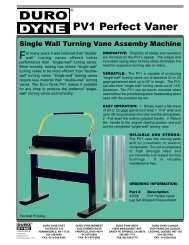
<strong>MF</strong>-<strong>12</strong><strong>MF</strong>-<strong>12</strong>PINSPOTTER<strong>MF</strong>-<strong>12</strong><strong>MF</strong>-<strong>12</strong>MACHINERYDIVISIONOWNER’SMANUAL
ELECTRICAL REQUIREMENTSConnect the <strong>MF</strong>-<strong>12</strong> to a 208-240 volts - 60 cycle - 30amp fused power supply. The <strong>MF</strong>-<strong>12</strong> unit uses 220volt single phase. To wire to 220 volt single phase,the green lead is ground and the white and black leadsare power. To wire to 220 volt three phase, the greenlead is ground and the white and black leads attach toany two of the other three legs. It is suggested thatthe unit not be wired into the power box permanentlybut rather plugged in so that the unit may be quicklyunplugged and easily taken elsewhere in the shop oron the job.<strong>MF</strong>-<strong>12</strong> AS A BENCH TOOLTo use your work bench as a welding table, set the<strong>MF</strong>-<strong>12</strong> alongside or on top of the work bench. Coverthe bench top with a copper sheet (.025 inch) whichwill act as a permanent ground when the duct workis placed on the table top. Attach the <strong>MF</strong>-<strong>12</strong> groundclamp to the duct work or copper bench top. The ClipPins will quickly weld every time with no burn marksor wasted pins due to misfires.BRING <strong>MF</strong>-<strong>12</strong> TO THE WORKWhere duct is too large to put on a bench, snap theground clamp onto the duct and secure the insulationquickly by welding the Clip Pins inside or outsideof the ducts as required. Eliminate the heat mark onthe duct using the simple "heat sink" supplied on theopposite side of the weld.SERVICEThe <strong>MF</strong>-<strong>12</strong> has been designed and built to withstandrugged shop and field usage. The Indicator lights onthe front panel will help you to diagnose minor problems.If your <strong>MF</strong>-<strong>12</strong> fails to operate follow this simpleprocedure to find the defective component.1. Pull the trigger and watch the lights. The green light (24volts) and then the red light (220 volts) should flashon and off.2. If only the green light comes on, go to step 4.3. If neither light comes on, press the WELDCYCLE TEST switch on the front panel.A. If both lights flash and the transformersdo not hum go to step 5.B. If both lights flash and the transformershum, the problem is either a bad triggerswitch or bad switch cable.C. If only the green light flashes, go to step 4D. If neither light flashes, replace 24 volttransformer.4. Replace the weld activator.5. The problem is probably a bad weld transformer.Call technical service for further assistance.(1-800-899-3876)TIMER ADJUSTMENTThe timer dial facing you on the front panel of theunit, determines the duration of the weld cycle. Formaximum efficiency of the unit, the weld cycle shouldbe set for the shortest length of time necessary toprovide a good weld. An excessive amount of time doesnot improve the weld. On the contrary, the resultingweld may not be an acceptable one. It is recommendedthat at the start of a production run, using a givenlength of pin with a given gauge of metal, the operatortake a few moments to determine the minimumtimer setting to perform the job and leave the timerat that point.NOTE: There is a common misconception that thelonger the weld time, the stronger the weld. This isnot true. It is important that you follow the above instructionsfor maintaining the minimum weld time."HEAT SINK"Included with your <strong>MF</strong>-<strong>12</strong> is a simple "heat sink" toolthat looks somewhat like a cookie cutter. This tool,when placed behind the point of weld on bare metal,will eliminate any mark on the metal by dissipating theheat generated from the point of the weld. The use ofa copper sheet on the work bench will also eliminatethis mark.MAINTENANCEThe <strong>MF</strong>-<strong>12</strong> has been designed and built to withstandrugged shop and field usage. Constant, trouble-freeoperation is assured with a minimum of maintenance.The GUN TIP, the GROUND CLAMP and all CABLE CON-NECTIONS should be kept clean to maintain a goodelectrical contact. Wire brush the parts to removeany oxidation or adhesive that may have accumulatedduring the fastening operation.INSTALLING CLIP PINSClip Pins are welded as easily as "A", "B", "C"."A"Position the Clip pin on theMagnetic tip of hand gun."B"Press down through the insulation,twist the gun, and pullthe trigger. Do not releasethe trigger until the timercycle has ended."C"The Clip Pins arepermanently weldedin position flush withthe insulation.
<strong>MF</strong>-<strong>12</strong> PARTS & SPECIFICATIONSITEM DESCRIPTION ITEM DESCRIPTION27005 TP-2 Tip17079 Rubber Foot27009 Heat Sink27321 Front Handle27315 Green Status Light27322 Top Handle27316 Red Status Light27323 Rear Handle27317 Power Light27217 Line Cord17309 Power Switch27253 Line Cord - Strain relief39110 Test Switch17313 Terminal Block27235 TP-8 Tip27256 Aluminum Connector Block27236 Fibre Sleeve27257 U-Clamp & Nuts27238 Roll Pin27325 <strong>MF</strong>-<strong>12</strong> Secondary Transformer27319 Case Body17327 Switch Cable Receptacle27320 Case Side Panel17288 Switch Cable PlugTransformer<strong>MF</strong>-<strong>12</strong>27237 Electrode27324 <strong>MF</strong>-<strong>12</strong> Primary Transformer27240 Case Screws17140 Weld Activator27244 Brass Jack17310 24V Transformer27245 Gun Switch27007 Gun & Cable Assembly27246 Gun Case27008 Ground Clamp Assembly27241 Switch Wire Assembly17320 Weld Potentiometer27243 Gun Cable / Electrode27326 Weld Potentiometer Knob27321 Electrode Assembly27213 Female Flush Mount Camlock27318 Case Top Cover with Handle 17049 Male Camlock<strong>MF</strong>-<strong>12</strong>
<strong>MF</strong>-<strong>12</strong> WIRING DIAGRAM
PARTS LOCATION27316 Red Status Light27317 Power Light17309 Power Switch27315 Green Status Light39110 Test Switch27213 FemaleFlush Mount Camlock17327 Switch CableReceptacle27321Front Handle17320 Weld Potentiometer27326 Knob27325 Secondary Transformer17140 WeldActivator17313 TerminalBlock1731024 Volt Transformer17079 Rubber Foot27324 Primary TransformerElectrode#27237Roll Pin#27238Switch Assembly# 27241Gun Switch#27245Heat Sink#27009FibreSleeve#27236Brass Jack# 27244CaseScrews# 27240Gun Cable# 27234Gun Case# 27239TP-8 Welding Tip# 27235
®<strong>MF</strong>-<strong>12</strong>®MACHINERY DIVISION© 2005 <strong>Duro</strong> <strong>Dyne</strong> CorporationPrinted in USA 01/2005BI027115