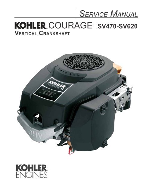
COURAGE SV470-SV620 - Kohler Engines
COURAGE SV470-SV620 - Kohler Engines
COURAGE SV470-SV620 - Kohler Engines

You also want an ePaper? Increase the reach of your titles
YUMPU automatically turns print PDFs into web optimized ePapers that Google loves.
ContentsSection 1. Safety and General Information .............................................................................Section 2. Tools & Aids.............................................................................................................Section 3. Troubleshooting ......................................................................................................Section 4. Air Cleaner and Air Intake System .........................................................................Section 5. Fuel System and Governor.....................................................................................Section 6. Lubrication System .................................................................................................Section 7. Electrical System and Components ......................................................................Section 8. Disassembly.............................................................................................................Section 9. Inspection and Reconditioning..............................................................................Section 10. Reassembly............................................................................................................12345678910
Section 1Safety and General InformationWARNINGWARNINGWARNINGand severe burns.engine is hot or running.Explosive Fuel!its vapors can explode if ignited. Storegasoline only in approved containers,in well ventilated, unoccupiedengine is hot or running, since spilledfuel could ignite if it comes in contactwith hot parts or sparks from ignition.Do not start the engine near spilledfuel. Never use gasoline as a cleaningagent.WARNINGCarbon Monoxide can causesevere nausea, fainting or death.Avoid inhaling exhaust fumes, andnever run the engine in a closedLethal Exhaust Gases!Engine exhaust gases containpoisonous carbon monoxide. Carbonmonoxide is odorless, colorless, and cancause death if inhaled. Avoid inhalingexhaust fumes, and never run thearea.severe acid burns.ventilated area. Keep sources ofignition away.Explosive Gas!gas while being charged. To prevent ain well ventilated areas. Keepof children. Remove all jewelry whenBefore disconnecting the negative(-) ground cable, make sure all switchesare OFF. If ON, a spark will occur atthe ground cable terminal which couldcause an explosion if hydrogen gas orgasoline vapors are present.Cleaning Solvents can causesevere injury or death.Use only in well ventilated areasaway from ignition sources.Flammable Solvents!Carburetor cleaners and solvents areaway from the area. Follow thecleaner manufacturer’s warnings andinstructions on its proper and safe use.Never use gasoline as a cleaning agent.CAUTIONElectrical Shock can cause injury.Do not touch wires while engine isrunning.Electrical Shock!Never touch electrical wires orcomponents while the engine isrunning. They can be sources ofelectrical shock.1.2
Section 1Safety and General InformationWhen ordering parts, or in any communicationinvolving an engine, always give the Model, of the engine.1A. Model No.Courage Vertical Shaft EngineNumerical DesignationSV 540 SVersion CodeS = Electric StartB. Spec. No.Engine ModelModel<strong>SV470</strong>SV480SV530SV540SV590SV600SV610<strong>SV620</strong>SV540-0001First specwritten in thismodel seriesC. Serial No.Year Manufactured CodeCode Year32 200233 200334 200435 200536 200637 200738 20083205810334Factory Code1.3
Section 1Safety and General InformationOil RecommendationsUsing the proper type and weight of oil in thecrankcase is extremely important, as is checking oilcorrect oil or using dirty oil causes premature enginewear and failure.Oil TypeUse high-quality detergent oil of . Selectthe viscosity based on the air temperature at the timeof operation as shown below.RECOMMENDED SAE VISCOSITY GRADESNOTE:** *5W-20, 5W-30Using other than service class SJ or higheroil or extending oil change intervals longerthan recommended can cause enginedamage.NOTE: Synthetic oils meeting the listedperformed at the recommended intervals.However to allow piston rings to properlyseat, a new or rebuilt engine should beoperated for at least 50 hours using standardpetroleum based oil before switching tosynthetic oil.SAE10W-30API SERVICE SJFigure 1-3. Oil Container Logo.10W-30<strong>Kohler</strong> 10W-30°F -20 0 20 32 40 60 80 100°C -30 -20 -10 0 10 20 30 40TEMPERATURE RANGE EXPECTED BEFORE NEXT OIL CHANGE* Use of synthetic oil having 5W-20 or 5W-30 rating is acceptable,up to 4°C (40°F)** Synthetic oils will provide better starting in extreme cold below-23°C (-10°F)Fuel RecommendationsWARNING: Explosive Fuel!if ignited. Store gasoline only in approved containers, inwell ventilated, unoccupied buildings, away from sparksor running, since spilled fuel could ignite if it comes incontact with hot parts or sparks from ignition. Do notstart the engine near spilled fuel. Never use gasoline as acleaning agent.General RecommendationsPurchase gasoline in small quantities and storein clean, approved containers. A container with arecommended. Such a container is easier to handleand helps eliminate spillage during refueling.season, to minimize gum deposits in your fuel systemand to ensure easy starting.Do not add oil to the gasoline.to expand.Fuel Typegasoline with a pump sticker octane rating of 87 orshould be 90 octane minimum.Unleaded gasoline is recommended, as it leaves lessbe used in areas where unleaded is not availableand exhaust emissions are not regulated. Be awarehowever, that the cylinder head will require morefrequent service.Gasoline/Alcohol Blendsgasoline by volume) is approved as a fuel for <strong>Kohler</strong>and E85 are not to be used and not approved. Anyfailures resulting from use of these fuels will not bewarranted.Gasoline/Ether BlendsMethyl Tertiary Butyl Ether (MTBE) and unleadedvolume) are approved as a fuel for <strong>Kohler</strong> engines.Other gasoline/ether blends are not approved.1.4
Section 1Safety and General InformationPeriodic MaintenanceWARNING: Accidental Starts!Disabling engine. Accidental starting can cause severe injury or death. Before working on the engine or equipment,1Maintenance ScheduleThese required maintenance procedures should be performed at the frequency stated in the table. They shouldalso be included as part of any seasonal tune-up.FrequencyDaily or BeforeStarting EngineEvery 2 Monthsor 25 HoursMaintenance Required Annually ortemperatures).Every 100 Hours • Check that all fasteners are in place and components are properly secured. Every 2 Years or • Check spark plug condition and gap.200 HoursEvery 200 Hours• Have bendix starter drive serviced².• Have valve lash checked/adjusted .Every 500 Hours ¹Perform these maintenance procedures more frequently under extremely dusty, dirty conditions.²Have a <strong>Kohler</strong> Engine Service Dealer perform this service.Storagemore, use the following storage procedure: • Check oil level.• Check air cleaner for dirty¹, loose, or damaged parts.• Check air intake and cooling areas, clean as necessary¹.• Service precleaner element¹ (if equipped).• Service air cleaner element¹ (if not equipped with precleaner). still warm from operation. See Change Oil and3. The fuel system must be completely emptied,or the gasoline must be treated with a stabilizeruse a stabilizer, follow the manufacturer’srecommendations, and add the correct amountcarburetor.To empty the system, run the engine until thetank and system are empty. the spark plug. The spark plug is most accessiblewhen the blower housing is removed forcleaning.Add one tablespoon of engine oil into the sparkthe plug lead. Crank the engine two or threerevolutions. Connect the plug lead. previously, and torque the blower housing screwsto . 1.5
Section 1Safety and General Information ............................................................................................................. ............................................................................................................. ............................................................................................................. .............................................................................................................. ............................................................................................................. .............................................................................................................. .............................................................................................................. .............................................................................................................. 1Bore ............................................................. ........................................................................ 89 mm (3.50 in.) ........................................................................Stroke...................................................................................................................... Displacement ............................................................. ........................................................................ ........................................................................ ........................................................................ ........................................................................Dry Weight............................................................................................................. 35.8 kg (79 lb.)..................................................................................... ...............Air Cleaner Base .................................................................................... .................... Blower Housing and Sheet Metal .................................................................. Cam Lever ...................................................... Cam GearsEnd Play .............................................................................................................. .................................................................................... ................................................. Carburetor................................................................. to assembly, EXCEPT for air cleaner base thread forming screw - install dry.1.7
Section 1Safety and General InformationClosure Plate ........................................................................ Balance Weight Guide Channel WidthNew.............................................................................................................. ......................................................................................... Connecting Rod.............................................. New............................................................................................................... .......................................................................................... ................................................ ....................................... Piston Pin End I.D.New............................................................................................................... .......................................................................................... CrankcaseNew............................................................................................................... .......................................................................................... Oil Drain Plug Torque ....................................................................................... CrankshaftEnd Play (free) .................................................................................................... New.............................................................................................................. ......................................................................................... New.............................................................................................................. ......................................................................................... ....................................................... ......................................................... ............................................................................. Max. Taper .................................................................................................. .................................................................................... PTO End Main Bearing Journal O.D. ........................................................ .......................................................... ............................................................................. Max. Taper .................................................................................................. .................................................................................... 1.8
Section 1Safety and General InformationCrankshaft (Continued) ........................................................ .......................................................... 1 ........................................................ .......................................................... New.............................................................................................................. ......................................................................................... Max. Taper .................................................................................................. .................................................................................... ............................................................... ................................................................. New.............................................................................................................. ......................................................................................... Balance WeightNew.............................................................................................................. ......................................................................................... Balance Weight Pin O.D.New.............................................................................................................. ......................................................................................... New ............................................................................................................. ......................................................................................... New.............................................................................................................. ......................................................................................... New.............................................................................................................. ......................................................................................... New.............................................................................................................. ......................................................................................... Balance Weight Screw Torque ......................................................................... 1.9
Section 1Safety and General InformationCylinder BoreNew .................................................................................. .................................................................................. ............................................................................................. ................................................................... .................................................................................. .................................................................................. ............................................................................................. 89.073 mm (3.507 in.) ................................................................... Max. Taper .................................................................................................. .................................................................................... Cylinder Head .......................... ........................................................................................ 0.8 mm (0.003 in.) ....................................................................... ........................................................ 5.5 N·m (50 in. lb.)Electric StarterThru Bolt Torque ............................................................................................... 3.3-3.9 N·m (30-35 in. lb.)Mounting Nut Torque ...................................................................................... ................................................. ............................................ Fan/Flywheel ......................................................... ......................................................... Governor........................... New.............................................................................................................. ......................................................................................... ..................... New ............................................................................................................. ........................................................................................ IgnitionSpark Plug Type (Champion ® or Equivalent) ............................................... Spark Plug Gap.................................................................................................. 1.10
Section 1Safety and General InformationIgnition (Continued)Spark Plug Torque............................................................................................. ................................................................................ 1 ................................................................... ...................................................................... Oil Filter ................................................................................................ Oil Filter Pad Pipe Plug .......................................................................................... Oil PumpMounting Screw Torque............................................................. Pump Gears-to-Crankcase Side Clearance.................................................... Oil SentryPressure Switch Torque.................................................................................... Piston, Piston Rings, and Piston PinNew.............................................................................................................. ......................................................................................... Piston Pin O.D.New.............................................................................................................. ......................................................................................... ..................................... ............................... New Bore .................................................................................................... .............................................................................................. Used Bore (max.)........................................................................................ 0.77 mm (0.030 in.) New............................................................................................................ ....................................................................................... New............................................................................................................ ....................................................................................... 1.11
Section 1Safety and General InformationPiston, Piston Rings, and Piston Pin (Continued)New............................................................................................................ ....................................................................................... New............................................................................................................ ....................................................................................... .................................................................... ....................................................... 0.0880 mm (0.0035 in.)Mounting Screw Torque................................................................................... Speed Control ...................................... StatorStator Mounting Screw Torque ....................................................................... Throttle/Choke Controls ..................................................... Valve Cover........................................................................... Valves and Valve Lifters 3 ............................................................................................. 3 .......................................................................................... ............................................................................. 8.9 mm (0.350 in.) .......................................................................... 8.9 mm (0.350 in.) ............................................................................... ............................... ............................ New.............................................................................................................. ......................................................................................... 31.12
Section 1Safety and General InformationValves and Valve Lifters (Continued)New.............................................................................................................. 1New.............................................................................................................. ......................................................................................... New.............................................................................................................. General Torque ValuesMetric Fastener Torque Recommendations for Standard ApplicationsTightening Torque: N·m (in. lb.) + or - 10%Property ClassNoncritical4.8 5.8 8.8 10.9 12.9 FastenersSizeM4 Into AluminumM5 M8 Tightening Torque: N·m (ft. lb.) + or - 10%Property Class4.8 5.8 8.8 10.9 12.9NoncriticalFastenersInto AluminumM10 M12 M14 Oil Drain Plugs Tightening Torque: N•m (English)Size1/8" NPT1/4"3/8"1/2"3/4"X-708-1Into Cast Iron–Into AluminumTorqueConversionsin. lb. = N·m x 8.851.13
Section 2Tools & AidsSection 2Tools & Aids2Separate Tool Suppliers:<strong>Kohler</strong> ToolsContact your sourceSE ToolsToolsDescriptionBalance Gear Timing Tool (K & M Series)Pressure TesterNoid LightSource/Part No.2.1
Section 2Tools & AidsTools (Continued)DescriptionTo remove and reinstall drive retaining rings and brushes.Individual Component AvailableStarter Brush Holding Tool (Solenoid Shift)Tachometer (Digital Inductive)For checking operating speed (RPM) of an engine.Vacuum/Pressure TesterAlternative to a water manometer.Valve Guide Reamer (K & M Series)For sizing valve guides after installation.Source/Part No.SE Tools KLR-82411SE Tools KLR-82416Design Technology Inc.DTI-110<strong>Kohler</strong> 25 761 22-SSE Tools KLR-118432.2
Section 2Tools & AidsAidsDescriptionLoctite® Ultra CopperSource/Part No.22.3
Section 2Tools & AidsSpecial Tools You Can MakeFlywheel Holding Tool . Figure 2-2. Rocker Arm/Crankshaft Tool.Figure 2-1. Flywheel Holding Tool.Rocker Arm/Crankshaft Tool 2.4
Section 3TroubleshootingSection 3TroubleshootingTroubleshooting GuideWhen troubles occur, be sure to check the simpleconsidered. For example, a starting problem could bebelow. Use these to help locate the possible cause(s).Engine Cranks But Will Not Start 5. Spark plug lead disconnected. 10. Choke not closing. Engine Starts But Does Not Keep Running 4. Loose wires or connections that short the kill Engine Starts Hard 7. Low compression. 9. Weak spark. restricted. Engine Will Not Crank 7. Seized internal engine components.Engine Runs But Misses 4. Spark plug lead boot loose on plug. ground. Engine Will Not Idle 7. Low compression. problem.33.1
Section 3TroubleshootingEngine Overheats shrouds clogged. Engine Knocks 4. Internal wear or damage. Engine Loses Power 8. Low compression.9. Exhaust restriction. Engine Uses Excessive Amount of Oil 3. Worn or broken piston rings. Oil Leaks from Oil Seals, Gaskets 2. Worn or broken piston rings. 4. Restricted exhaust.External Engine Inspectionwhen it is disassembled. maintenance.odor.used, the oil was not changed at the recommendedNOTE: It is good practice to drain oil at a locationCleaning the Engineengine parts. When such a cleaner is used, followthe manufacturer’s instructions and safety precautionscarefully.3.2
the engine is reassembled and placed into operation.Basic Engine TestsCrankcase Vacuum Testcrankcase when the engine is operating. Pressuretesters. Be sure the pinch clamp is installed on thehose and use the tapered adapters to connectmanometer is at the “0” line. Make sure the pinchclamp is closed.Section 3Troubleshooting2. Start the engine and run at no-load high idlespeed (3200 to 3750 RPM). tube. 10.2 cm (4 in.) below.4. Close the pinch clamp before stopping theengine.1. Insert the stopper as in step 1.stopper. Be sure the gauge needle is at “0”. 3Incorrect Vacuum in CrankcasePossible CauseSolution reassemble, and recheck pressure. 4. Restricted exhaust.2. Replace all worn or damaged seals and gaskets. 3.3
Section 3TroubleshootingCompression TestThese engines are equipped with an automaticleakdown test described below.Cylinder Leakdown TestLeakdown Test Instructions will need to hold the engine in this positionwhile testing. The holding tool supplied witha shoulder bolt through the slot and thread it intoTDC in either direction.4. Install the adapter into the spark plug hole, but5. Connect an adequate air source (80-100 psi) to thetester.6. Turn the regulator knob in the increase(clockwise) direction until the gauge needle is inscale.7. Connect the tester quick-disconnect to theescaping air at the carburetor inlet, exhaust Leakdown Test Results ................................................ .....................................................................................................................Gauge reading in low (green) zone ..............................................................................................Engine is still usable, but there is some wearGauge reading in high (red) zone........................................................Engine should be reconditioned or replaced.3.4
Section 4Air Cleaner and Air Intake SystemSection 4Air Cleaner and Air Intake SystemAir CleanerThese engines are equipped with a replaceable, highdensity, paper air cleaner element. Some engines alsohave an oiled, foam precleaner, located in the outer aircleaner cover. See Figure 4-1.Intake air is drawn in through the upper opening fromthe blower housing, passes through the precleaner(if so equipped), the paper element and then intothe carburetor. The outer air cleaner cover is securedby two knobs, and removed by turning the knobscounterclockwise.4Air CleanerBaseAir Cleaner ElementAir Cleaner CoverOptional Foam PrecleanerAirCleanerCoverKnobsFigure 4-1. Air Cleaner Assembly - Exploded View.Check the air cleaner daily or before starting theengine. Check for and correct any buildup of dirt anddebris, and loose or damaged components.NOTE: Operating the engine with loose ordamaged air cleaner components couldpremature wear and failure.Precleaner ServiceIf so equipped, wash and oil the precleaner every twomonths or every 25 hoursunder extremely dusty or dirty conditions).1. Loosen the air cleaner cover knobs and removethe cover.2. Remove the precleaner.4.1
Section 4Air Cleaner and Air Intake System3. Wash the precleaner in warm water withdetergent. Rinse the precleaner thoroughly untilall traces of detergent are eliminated. Squeeze outexcess water (do not wring). Allow the precleanerto air dry.4. Saturate the precleaner with new engine oil.Squeeze out all excess oil.5. Reinstall the precleaner into the outer cover.6. Install the air cleaner cover and secure with thetwo knobs.7. When precleaner replacement is necessary, order<strong>Kohler</strong> Part No. 20 083 03-S.Paper Element ServiceCheck the paper element every two months or every25 hoursdusty or dirty conditions). Clean or replace theelement as necessary. Replace the air cleaner elementannually or every 100 hours.1. Remove the air cleaner cover and the precleaner(if so equipped), service as required.2. Remove the air cleaner element with the integralrubber seal.8. When element replacement is necessary, order<strong>Kohler</strong> Part No. 20 083 02-S.Inspect Air Cleaner ComponentsWhenever the air cleaner cover is removed, or thepaper element or precleaner is serviced, check thefollowing areas/components:Outer Air Cleaner Cover - Make sure the air cleanercover is in good condition, not cracked, damaged, orability of the air cleaner element.Air Cleaner Base - Make sure the base is properlysecured and not cracked or damaged. Since theair cleaner base and carburetor are secured to theintake port with common hardware, it is extremelyimportant that the fasteners securing thesecomponents are tight at all times. The air cleanerbase also provides the mounting points for the aircleaner cover retaining studs. Make sure the bossesare not cracked, broken or damaged, and the studs areproperly secured.Before reinstalling an air cleaner base that has beenremoved, make sure the metal bushings in the basemounting holes are present. See Figure 4-2. Thebushings prevent damage to the base and maintainthe proper mounting torque.3. Gently tap the pleated side of the paper elementto dislodge dirt. Do not wash the paper elementor use pressurized air, as this will damage theelement. Replace a dirty, bent, or damagedelement with a genuine <strong>Kohler</strong> element. Handlenew elements carefully; do not use if the rubberseal is damaged.4. Clean all air cleaner components of anyaccumulated dirt or foreign material. Prevent anydirt from entering the throat of the carburetor.5. Install the air cleaner element with the pleatedside out and seat the rubber seal onto the edgesof the air cleaner base.6. Reinstall the precleaner (if so equipped), intothe upper section of the air cleaner cover. Makesure the hole in the precleaner is aligned with theupper mounting knob. See Figure 4-1.7. Reinstall the air cleaner cover and secure with thetwo knobs.Figure 4-2. Bushings in Air Cleaner Base.Breather Hose - Make sure the hose is not cracked orand valve cover.NOTE: Damaged, worn, or loose air cleanerengine causing premature wear and failure.Tighten or replace all loose or damagedcomponents.4.2
Section 4Air Cleaner and Air Intake SystemFigure 4-3. Breather Hose.DisassemblyThe following procedure is for complete disassemblyof all air cleaner components. As the removal of thegovernor adjustment, steps 3 and 4 should only beperformed if required. Detailed photos are providedin Sections 5, 8, and 10 for the various individualsteps.1. Loosen the air cleaner cover retaining knobs andremove the air cleaner cover.2. Remove the foam precleaner (if so equipped),and the air cleaner element with formed rubberseal.3. Disconnect the breather hose from the valvecover or air cleaner base.NOTE: The air cleaner base should be removedonly if necessary. mounting studs. If one stud and one threadforming screw on the right side of the carburetorinlet, which secures the air cleaner base,carburetor and gaskets. Insert a 3/16” diameterrod approximately 4” long, into the hole to serveas a temporary alignment pin. Be careful notto force the rod or damage the threads. Thenremove the air cleaner base and gasket. The covermounting studs thread into the air cleaner base,and they should only be removed if necessary.ReassemblyThe following procedure is for complete assembly ofall air cleaner components. Steps 1-3 are necessaryonly if the air cleaner base and/or the cover mountingstuds were removed in Section 8, Disassembly.1. Install the mounting studs into the air cleanerbase if removed previously. Tighten the studsforce).2. Install the air cleaner base gasket and air cleanerbase, with the two metal spacers, onto themounting stud(s) and/or alignment pin. Makesure the upper mounting tab is located above themounting screw is used, apply hand pressurealignment pin and install the M6 thread formingscrew. DO NOT OIL. Torque the nut(s) to5.5 N·m (48 in. lb.). Torque the screw to 8.0 N·m(70 in. lb.) into a new hole, or 5.5 N·m (48 in. lb.)into a used hole, do not over tighten.3. Reconnect the breather hose and perform thegovernor adjustment (Section 5, Initial GovernorAdjustment).4. Install the air cleaner element with the pleatedside out and seat the rubber seal onto the edgesof the air cleaner base.5. Install the serviced precleaner (if so equipped)into the air cleaner cover. Make sure the holein the precleaner is aligned with the uppermounting knob.6. Reinstall the air cleaner cover and secure with thetwo knobs.44.3
Section 4Air Cleaner and Air Intake SystemAir Intake/Cooling SystemClean Air Intake/Cooling AreasTo ensure proper cooling, make sure the grass screen,are kept clean at all times.Annually or every 100 hoursunder extremely dusty, dirty conditions), remove theblower housing and any other cooling shrouds. CleanMake sure all parts are reinstalled. Torque the M6blower housing fasteners to 7.7 N·m (68.3 in. lb.).NOTE: Operating the engine with a blocked grasscooling shrouds removed, will cause enginedamage due to overheating.4.4
Section 5Fuel System and GovernorSection 5Fuel System and GovernorFuel RecommendationsWARNING: Explosive Fuel!General RecommendationsPurchase gasoline in small quantities and storein clean, approved containers. A container with acapacity of 2 gallons or less with a pouring spout isrecommended. Such a container is easier to handleand helps eliminate spillage during refueling. season, to minimize gum deposits in your fuelsystem and to ensure easy starting.• Do not add oil to the gasoline. fuel to expand.Fuel TypeFor best results, use only clean, fresh, unleadedhigher. In countries using the Research method, itshould be 90 octane minimum.Unleaded gasoline is recommended, as it leaves lessbe used in areas where unleaded is not availableand exhaust emissions are not regulated. Be awarehowever, that the cylinder head will require morefrequent service.Gasoline/Alcohol blendsGasohol (up to 10% ethyl alcohol, 90% unleadedgasoline by volume) is approved as a fuel for <strong>Kohler</strong>engines. Other gasoline/alcohol blends including E20failures resulting from use of these fuels will not bewarranted.Gasoline/Ether blendsMethyl Tertiary Butyl Ether (MTBE) and unleadedvolume) are approved as a fuel for <strong>Kohler</strong> engines.Other gasoline/ether blends are not approved.Fuel SystemThe typical fuel system and related componentscarburetor, and fuel lines. Some applications usegravity feed without a fuel pump.Operationlocated above the carburetor inlet and gravity movesthe fuel.moved into the carburetor body. There, the fuel isthe engine combustion chamber.Troubleshootingreaching the combustion chamber.55.1
Section 5Fuel System and GovernorTest proper fuel. the tip. the fuel pump. the carburetor. Fuel FilterReplacement is recommended annually or every 100hoursFuel System Troubleshooting GuideConclusion2. If there isreaching the combustion chamber.If there is no doesIf fuel does notvalve, and fuel lines. doescarburetor. (Refer to the "Carburetor" portions ofthis section.)If fuel does notclogged fuel line. If the fuel line is unobstructed,the fuel pump is faulty and must be replaced.carburetor.Fuel PumpSome engines are equipped with an optional pulseOperationThe fuel pump has two internal chambers separatedby a diaphragm. The air chamber is connected to thecarburetor. The inlet and outlet each have an internal,Alternating negative and positive pressures in theupward in the cylinder, negative pressure (vacuum)pressure, and the suction draws fuel past the inletmovement of the piston causes a positive pressureRepairPulse fuel pumps are not serviceable and must bereplaced when faulty.Removal1. Disconnect the inlet, outlet, and pulse linesreassembly. pump.Installation1. Install the new fuel pump, and secure with theto 5.9 N·m (52 in. lb.). Do not over tighten.2. Connect the inlet, outlet, and pulse lines to their5.2
Section 5Fuel System and GovernorTroubleshooting – Fuel SystemIf engine troubles are experienced that appear to beadjusting or disassembling the carburetor. gasoline. that it is operating properly.Figure 5-1. Pulse Fuel Pump.Carburetorhave a low idle speed adjustment screw, and eitherneedle. fuel pump (as equipped), for restrictions or faultycomponents.good condition.air cleaner components are fastened securely.5 are operating properly.problems or conditions similar to those listed in thefollowing table exist, it may be necessary to adjust orservice the carburetor.Figure 5-2. Carburetor.WARNING: Explosive Fuel5.3
Section 5Fuel System and GovernorCondition1. Engine starts hard, runs roughlyor stalls at idle speed.2. Engine runs rich. (Indicatedgovernor hunting, or excessive governor hunting, or excessive Carburetor AdjustmentNOTE: Carburetor adjustments should be made onlyTroubleshooting – Fuel SystemPossible Cause/Probable Remedy idle speed screw, then adjust the low idle fuel needle. fuel needle. d. Dirt under fuel inlet needle. Remove needle; clean needle andseat and blow with compressed air.e. Bowl vent or air bleeds plugged. Remove fuel bowl, low idlefuel adjusting needle, and welch plugs. Clean vent, ports, and airbleeds. Blow out all passages with compressed air. fuel needle. c. Idle holes plugged; dirt in fuel delivery channels. Remove fuelbowl, low idle fuel adjusting needle, and welch plugs. Cleanmain fuel jet and all passages; blow out with compressed air. b. Dirt under fuel inlet needle. See Remedy 2d.c. Bowl vent plugged. Remove fuel bowl and clean bowl vent. Blowout with compressed air. The carburetor is designed to deliver the correctconditions. The main fuel jet is calibrated at thefactory and is not adjustable*. The idle fuel adjustmentneedle is also set at the factory and normally does notneed adjustment. If the engine is hard starting or doesnot operate properly, however, it may be necessary toadjust or service the carburetor.Idle FuelMixture NeedleIdle Speed (RPM)Adjustment Screw a special high altitude main jet. Refer to HighAltitude Operation later in this section.Figure 5-3. Fixed Main Jet Carburetor.5.4
Section 5Fuel System and GovernorLow Idle Mixture Adjustment*NOTE: possible) or a limiter cap on the idle fueladjustment needle. Step 2 can only beperformed within the limits allowed by thecap. minutes to warm up. The engine must be warmbefore doing step 2.2. into the idle or slow position.Turn the low idle fuel adjustment needle outuntil engine speed decreases (rich). Note theposition of the needle. The engine speed may increase, then it willdecrease as the needle is turned in (lean). Notethe position of the needle.Set the adjusting needle midway between the richAdjust to MidpointLeanLow Idle Speed Setting minutes to warm up. The engine must be warmbefore doing step 2.2. control into the idle or slow position. Set thelow idle speed by turning the low idle speedadjusting screw in or outa tachometer.the application–refer to equipmentmanufacturer’s recommendations. Therecommended low idle speed for basic5RichFigure 5-4. Optimum Low Idle Fuel Setting.will compensate for speed changes due to thelow idle mixture adjustment. Disable theadjustment and then reset the governed idlespeed at the adjusting screw.5.5
Section 5Fuel System and GovernorDisassemblyThrottle Lever and ShaftDust SealThrottle Plate Screw(s)Choke Lever and ShaftThrottle PlateChoke Return SpringLow Idle Speed AdjustingScrew and SpringChoke PlateLow Idle Fuel AdjustingNeedle and Spring withLimiter CapFuel InletNeedleFloatFloat ShaftBowl GasketFuel BowlFuel Shut-off SolenoidorBowl Retaining Screw GasketBowl Retaining ScrewFigure 5-5. Carburetor - Exploded View. fuel inlet needle. Do notadjustment needle if it has a limiter cap.Further disassembly to remove the welch plugs,parts are to be cleaned or replaced.Welch Plug RemovalIn order to clean the idle ports and bowl ventthoroughly, remove the welch plugs covering theseareas.Use SPX Tool No. KO-1018 and the following1. Pierce the welch plug with the tip of the tool. body.2. Pry out the welch plug with the tip of the tool.5.6
Section 5Fuel System and GovernorTool No. KO1018 Do Not AllowTip to StrikeCarburetor BodyPry Out PlugPierce Plug with TipFigure 5-6. Removing Welch Plug.Welch PlugMain Fuel Jet RemovalThe main jet is pressed into the side of the towerportion of the body. Removal is not recommended,case the removal instructions will be included in theFuel Inlet Seat RemovalThe fuel inlet seat is pressed into the carburetor body,do notplace with aerosol carburetor cleaner.Choke Shaft Removal return spring.Figure 5-7. Marking Choke Plate and CarburetorBody.Figure 5-8. Removing Choke Plate. Throttle Shaft RemovalDo notaccompanied by corresponding wear to the carburetorCleaningWARNING: Flammable Solvents!All parts should be cleaned thoroughly using adeposits are removed from the following areas.• Carburetor body and bore; especially the areasare seated.• Idle fuel and idle ports in carburetor bore, mainjet, bowl vent, and fuel inlet needle and seat.• Fuel bowl.55.7
Section 5Fuel System and Governor installed. The cleaner may damage thesecomponents.InspectionCarefully inspect all components and replace thosethat are worn or damaged. other wear or damage.Welch Plug InstallationUse SPX Tool No. KO1017 and install new plugs as1. Position the carburetor body with the welch plugcavities to the top.2. Place a new welch plug into the cavity with theraised surface up. Do not force theplug below the surface of the cavity. See Figure for wear or damage.• Inspect the fuel inlet needle and seat for wear ordamage.• Inspect the tip of the low idle fuel adjustmentneedle for wear or grooves. assemblies for wear or excessive play.RepairAlways refer to the Parts Manual for the engine beingReassemblyChoke Shaft Installation the carburetor body. counterclockwise Tool No. KO1017Carburetor BodyFigure 5-9. Installing Welch Plugs.New Welch Plug Glyptal (or an equivalent sealant). Allow thesealant to dry. Carburetor Reassembly1. Install the low idle speed adjusting screw andspring.2. If the low idle fuel adjusting needle containsa limiter, adjust to the midpoint within theadjustment range. 5.8
Section 5Fuel System and GovernorFigure 5-10. Installing Float and Fuel Inlet Needle. solenoid.Torque the bowl retaining screw to 5.1-6.2 N·m(45-55 in. lb.).Fuel Shut-off Solenoidsolenoid installed in place of the bowl retaining screwsolenoid, verify that the correct shutdown procedurethe engine must be running between half and fullthe carburetor body to the air cleaner base mountingscrew is properly connected.and catch any fuel spilling from the carburetor as thesolenoid is removed.Bench test the solenoid by grounding the solenoidcase and applying 12 volt DC to the spade terminal. Ifthe plunger does not retract, the solenoid is faulty andwhenever the solenoid is installed. Refer to the wiringsolenoid.Figure 5-11. Fuel Shut-Off Solenoid.High Altitude Operationof speed and power, poor fuel economy, and poor orslow governor response.high altitude main jet can be installed. High altitudeUnitized Throttle and Choke ControlThrottle Cable Adjustment CableClamp5Figure 5-12. Speed Control Bracket with UnitizedThrottle/Choke Control.5.9
Section 5Fuel System and Governor into the fast or high speed position. The actuatingChokeAdjustmentScrewAlignment HoleFigure 5-15. Alignment Hole in Speed ControlBracket and Throttle Lever. (Early Models)Figure 5-13. Adjusting Unitized Throttle/ChokeControl. travel past the fast position. This willLater Models:by matching the hole in the control lever with thealign the hole in the lever with the correct hole in clamp securely.Cold EngineWarm EngineFigure 5-14. Typical Throttle/Choke Controls. Early Models: Early models use a singlealignment hole to set the engine RPM. AlignAlignment Holefor 3000 RPMand HigherAlignment Holefor Less Than3000 RPMFigure 5-16. Alignment Holes in Speed ControlBracket and Throttle Lever. (Later Models)5.10
Section 5Fuel System and GovernorStarting an Engine Equipped with UnitizedThrottle and Choke Control1. fast/choke on position.on For Operation fast/chokeon position and set the desired engine operatingspeed (between the slow and fast position).High Speed (RPM) Adjustment(RPM) for most engines is 3300 RPM. The actual highspeed (RPM) depends on the application. Refer to theinformation.WARNING: Overspeed is Hazardous! 5Figure 5-17. Throttle Position for Starting Engine. soon as the engine starts. for more than 10 seconds at a time.If the engine does not start, allow athese guidelines can burn out the startermotor. to disengage the starter but does notrotation must be allowed to come toto restart the engine. If the starter ismay clash, resulting in damage to thestarter.If the starter does not turn the engine over, shut theDo notto start the engine until the condition is corrected. Dotrouble analysis.2. Start the engine and allow it to warm up. Place Early Models: Early models use a singlealignment hole to set the engine RPM. AlignLater Models:instead of one. Based upon the intended highmust be made matching the hole in the controllever with the appropriate alignment hole. Uselever with the appropriate hole in the control until the desired high speed (RPM) is reached.tachometer.5.11
Section 5Fuel System and Governor gentle pressure towards the carburetor. If thenot move.Separate Throttle and Choke ControlFigure 5-18. Adjusting High Speed (RPM)., move the, move the readjust if necessary. Install Separate Control CablesThrottle Control Installation control plate. 11.0 N·m (95 in. lb.).Into used hole – 7.5 N·m (65 in. lb.). follows).Choke AdjustmentThis procedure must follow the High SpeedAdjustment just described. If not already completed, out in control lever to the low idle (slow) position, thenout until it no longer moves.Figure 5-19. Separate Choke and Throttle CableControls.ChokeCable ClampThrottleCable ClampEarly Models: Early models use a singlealignment hole to set the engine RPM. Align5.12
Section 5Fuel System and Governor control to ensure it stops against the stop screw,which means it is properly set.Alignment HoleFigure 5-20. Alignment Hole in Speed ControlBracket and Throttle Lever. (Early Models)Later Models:instead of one. Based upon the intended highmust be made matching the hole in the controllever with the appropriate alignment hole. Uselever with the appropriate hole in the control clamp securely.Alignment Holefor 3000 RPMand HigherAlignment Holefor Less Than3000 RPMFigure 5-21. Alignment Holes in Speed ControlBracket and Throttle Lever. (Later Models)Choke Control Installation assembly. position stops. Do not force. Then tighten the cable clampscrew. on Starting an Engine Equipped with SeparateControl Cables slow and fastinto the on position.2. Start the engine. and warms up.The engine/equipment may be operated duringthe warm up period, but it may be necessarywarms up. as soon as engine starts.55.13
Section 5Fuel System and GovernorChanging the High Speed (RPM) on the <strong>Engines</strong>with Separate Controls (Increase or DecreaseRPM) matches the intended high speed RPM operating lever pivot) rather than one. Based upon the intendedmade matching the hole in the control lever with theappropriate alignment hole.The system requires an additional procedure forrequired proceed as follows. following the appropriate instructions alreadycovered in this section. Hold the governor lever away from theFigure 5-22. Adjusting High Speed (RPM). To increase the RPM: Move the speed controlTo decrease theRPM: it with a tachometer against the equipmentmanufacturers recommended idle speed. Ifadjustment is necessary, use the governed idleadjusting screw on the speed control assemblyto increase the governed idle speed and a tachometer.Setting the Low Idle RPM1. Move the application control to slow position. a screwdriver, turn the low idle speed screw (seethe RPM.Governed Idle AdjustmentA governed idle control system was supplied asa option on early engines and is standard on latermodel engines. The purpose of this system is tomaintain a desired idle speed regardless of ambientconditions (temperature, parasitic load, etc.) that maytwoGoverned IdleAdjusting ScrewFigure 5-23. Location of Governed Idle AdjustingScrew.GovernorThese engines are equipped with a centrifugalthe engine speed constant under changing load5.14
Section 5Fuel System and GovernorNOTE: Flyweights must be installed perpendicularto the nylon gear as shown. ImproperFlyweightsNylon GearFigure 5-24. Governor Gear/Flyweight Assembly.OperationAs the governor gear rotates, centrifugal force causesregulating pin to move outward.governor lever is clamped on the protruding end offast position, the tension of the governor spring holds(the governor gear assembly is rotating), the forcetension and the force applied by the regulating pin arein equilibrium during operation, holding the enginespeed constant.governor gear speed) decreases, the governor springplate wider. This allows more fuel into the engine;rapidly, so a reduction in speed is hardly noticed. Asspring tension and the force applied by the regulatingpin will again be in equilibrium. This maintains theengine speed at a relatively constant level.constant, depending on the application.Initial Adjustment1. Move the governor lever toward the carburetorDo not apply excess force counterclockwise as far as it will go, thentighten the hex nut. Torque the hex nut to7.0-8.5 N·m (60-75 in. lb.).Figure 5-25. Governor Adjustment.Figure 5-26. Tightening Governor Lever Nut.5.155
Section 5Fuel System and GovernorGovernor Sensitivity AdjustmentGovernor sensitivity is adjusted by repositioning thegovernor spring in the holes in the governor lever.If speed surging occurs with a change in load, thegovernor is set too sensitive. If a big drop in speedoccurs when a normal load is applied, the governorshould be set for greater sensitivity.the governor spring position in the governor leverThrottleLeverGovernorLever1132SingleAlignmentHole2 3High SpeedRPMGovernedIdle RPMGovernedLever Hole No.Figure 5-27. Early Style Governor Spring Location Chart.Throttle LeverHole No.WhiteSpringGreenSpringBlackSpring3201-3400 2 2 X3201-3400 2 2 X3201-3400 1601-1800 2 2 X12ThrottleLever3GovernorLever(Single Hole)SingleHoleGovernorLever(Multiple Hole)321AAlignment Holefor 3000 RPMand HigherBAlignment Holefor Less Than3000 RPMHigh SpeedRPMGovernedIdle RPMGovernedLever Hole No.Throttle LeverHole No.RedSpringAlignmentHoleLess than 3000 RPM 2/Single Hole 2 X BLess than 3000 RPM 2/Single Hole 2 X AFigure 5-28. Later Style Governor Spring Location Chart.5.16
Section 6Lubrication SystemSection 6Lubrication SystemOil RecommendationsUsing the proper type and weight of oil in thecrankcase is extremely important. So is checking oildaily and changing oil regularly. Failure to use thecorrect oil, or using dirty oil, causes premature enginewear and failure.Oil TypeUse high-quality detergent oil of API (AmericanPetroleum Institute) service class SJ or higher. Selectthe viscosity based on the air temperature at the timeof operation as shown in the following table.RECOMMENDED SAE VISCOSITY GRADES** *5W-20, 5W-30Figure 6-1. Viscosity Grades Table.10W-30<strong>Kohler</strong> 10W-30°F -20 0 20 32 40 60 80 100°C -30 -20 -10 0 10 20 30 40TEMPERATURE RANGE EXPECTED BEFORE NEXT OIL CHANGE* Use of synthetic oil having 5W-20 or 5W-30 rating is acceptable,up to 4°C (40°F)** Synthetic oils will provide better starting in extreme cold below-23°C (-10°F)SAE10W-30API SERVICE SJFigure 6-2. Oil Container Logo.Check Oil LevelThe importance of checking and maintainingthe proper oil level in the crankcase cannot beoveremphasized. Check oil BEFORE EACH USE asfollows:1. Make sure the engine is stopped, level, and iscool so the oil has had time to drain into thesump.2. To keep dirt, grass clippings, etc., out of thedipstick before removing it.6NOTE:Using other than service class SG, SH, SJ orhigher oil or extending oil change intervalslonger than recommended can cause enginedamage. Figure 6-3. Reinsert the dipstick into the tube andfully seat the dipstick in the tube. See Figure 6-4. may be used with oil changes performedat the recommended intervals. However toallow piston rings to properly seat, a new orrebuilt engine should be operated for at least50 hours using standard petroleum based oilbefore switching to synthetic oil.service class and SAE viscosity grade. See Figure 6-2.6.1
Section 6Lubrication SystemNOTE:To prevent extensive engine wear ordamage, always maintain the proper oillevel in the crankcase. Never operatethe engine with the oil level below the‘‘L’’ mark or over the ‘‘F’’ mark on thedipstick.Figure 6-3. Removing Dipstick.Change Oil and Oil Filterannually or every 100hoursand carry away more impurities. Make sure theAlways use.Oil FilterFigure 6-4. Dipstick Seated.4. Remove the dipstick and check the oil level. Theoil level should be up to, but not over the ‘‘F’’mark on the dipstick. See Figure 6-5.Figure 6-6. Oil Drain Plug, Oil Filter.Oil Drain Plug1. To keep dirt, grass clipping, etc., out of thedipstick before removing it. Be sure to allow ample time for completedrainage.OperatingRangeFigure 6-5. Oil Level Dipstick. to the ‘‘F’’ mark on the dipstick. Always check thelevel with the dipstick before adding more oil. pad.4. Reinstall the oil drain plug and torque to 14 N·m(125 in. lb.). type, in through the threaded center hole. Stopthreads. Allow a minute or two for the oil to be 6.2
Section 6Lubrication System an additional 3/4 to 1 turn..8. Fill the crankcase with new oil of the proper type,to the “F” mark on the dipstick. into place.10. Test run the engine to check for leaks. Stop theengine, allow a minute for the oil to drain down,and recheck the level on the dipstick. Add moreoil, as necessary, so the oil level is up to but notover the “F” mark.NOTE:To prevent extensive engine wear ordamage, always maintain the proper oillevel in the crankcase. Never operatethe engine with the oil level below the‘‘L’’ mark or over the ‘‘F’’ mark on thedipstick.Full-Pressure Lubrication SystemOperationThis engine uses a full-pressure lubrication systemto deliver oil for internal lubrication. A cam driven, oil pump located in theeven at low speeds and high operating temperatures.Oil is supplied from the pump via two circuits to theintegral pressure relief valve within the oil pumplimits the maximum pressure of the system.For a cold engine at start up, the oil pressure cango down to 5 psi.ServiceThe oil pump rotors typically require no servicing, ifnormal maintenance is performed as outlined inSection 1.The closure plate must be removed for access to theoil pump and the rotors. Refer to the Disassemblyreinstallation procedures.Figure 6-7. Oil Pump on Intake Cam Shaft(Gerotors Removed from Pump Housing).Oil FilterSee Figure 6-8.the oil change interval and cools the oil.Figure 6-8. Oil Filter Location.Oil FilterOil Sentry Some engines are equipped with an optional OilSentry low, Oil Sentry will either activate a low oil warninglight or stop the engine, depending on the application.OperationThe pressure switch is designed to break contactas the oil pressure increases and make contact asthe oil pressure decreases. At oil pressure aboveapproximately 2 to 5 psi, the switch contacts open.At oil pressures below approximately 2 to 5 psi, theswitch contacts close.66.3
Section 6Lubrication Systemapplications, the pressure switch can be used toground the ignition module to stop the engine.NOTE:Oil Sentry is not a substitute for checkingthe oil level BEFORE EACH USE. Make surethe oil level is maintained up to the ‘‘F’’ markon the dipstick. See Figure 6-5.InstallationThe pressure switch is installed into the center oilBased on the application an elbow adapter may alsobe used. See Figure 6-9. On engines not equipped withOil Sentry plug or completely sealed.Testing the Oil Sentry SwitchThe Oil Sentry pressure monitor is a normally closeddecreasing pressure within the range of 2.0/5.0 psi.Compressed air, a pressure regulator, pressure gauge,and a continuity tester are required to test the switch.1. Connect the continuity tester across the bladeterminal and the metal case of the switch. With0 psi pressure applied to the switch, the testershould indicate continuity (switch closed).2. Gradually increase the pressure to the switch. Thetester should indicate a change to no continuity(switch open) as the pressure increases throughthe range of 2.0/5.0 psi.The switch should remain open as the pressure isincreased to 90 psi maximum.3. Gradually decrease the pressure to the switch.The tester should indicate a change to continuity(switch closed) as the pressure decreases throughthe range of 2.0/5.0 psi; approaching0 psi.Oil Sentry (External)Figure 6-9. Oil Sentry Pressure Switch Locations.To install the Oil Sentry switch:Oil Sentry (BehindBlower Housing)1. Remove and discard the pipe plug from the2. Apply ® ® No. switch. it to the intended position. Do not over tighten ordamage the adapter. passage. Torque the switch to 4.5-5.0 N·m(40-45 in. lb.).5. Connect the lead to the terminal on the OilSentry switch. replace the switch.Testing Oil PressureOn some models the engine oil pressure can be testedusing an oil pressure tester. Follow the instructionsincluded with the tester. The pressure can be tested byon the mounting pad, or by removing the Oil Sentry hose directly into the mounting hole. See Figure 6-10.LocationsFor TesterFigure 6-10. Tester Locations (Some Models).6.4
Section 7Electrical System and ComponentsSection 7Electrical System and ComponentsThis section covers the operation, service, and repair of the electrical system and electrical system components.charging systems, electric starter, and optional Oil Sentry oil level pressure switch.WARNING: Electrical ShockNever touch electrical wires or components while the engine is running. They can be sources of electrical shock.Spark Plugby a spark plug that is in poor condition or has anThe engine is equipped with the following spark plug:Type:GapThread Size:Reach:Hex Size:Champion ® RC12YC orQC12YC (RFI Compliant)0.76 mm (0.030 in.)14 mm19.1 mm (3/4 in.)15.9 mm (5/8 in.)Spark Plug ServiceEvery 2 years or 200 hours of operation, remove thespark plug. Check its condition, and reset the gapor replace with a new plug as necessary. Spark plugreplacement is recommended at 500 hours.1. Before removing the spark plug, clean the areaaround the base of the plug to keep dirt anddebris out of the engine. Due to the deep recessaround the spark plug, blowing out the cavitymethod for cleaning. The spark plug is mostaccessible when the blower housing is removedfor cleaning.2. Remove the plug and check its condition. Replacethe plug if worn or reuse is questionable.NOTE:Do not clean the spark plug in a machineusing abrasive grit. Some grit couldremain in the spark plug and enter theengine, causing extensive wear anddamage.3. Check the gap using a wire feeler gauge.Adjust the gap by carefully bending the groundelectrode. Gap plugs to 0.76 mm (0.030 in.). SeeFigure 7-1.Wire GaugeSpark PlugGroundElectrodeFigure 7-1. Servicing Spark Plug.0.76 mm(0.030 in. )Gap4. Reinstall the spark plug into the cylinder head.Torque the spark plug to .5. Reconnect the spark plug lead and reinstall theblower housing, if removed previously. Torque theblower housing screws to .77.1
Section 7Electrical System and ComponentsInspectionInspect the spark plug as soon as it is removed fromthe cylinder head. The deposits on the tip are anindication of the general condition of the piston rings,valves, and carburetor.Normal and fouled plugs are shown in the followingphotos. Chalky white coloreddeposits indicate overheating. This condition isusually accompanied by excessive gap erosion. Acarburetion are some causes of overheating. A plug taken from an engine operating undernormal conditions will have light tan or gray coloreddeposits. If the center electrode is not worn, a plug inthis condition could be regapped and reused.incomplete combustion. Incomplete combustionis usually caused by over-rich carburetion, weakignition, or poor compression.Worn: On a worn plug, the center electrode will berounded and the gap will be eroded .010" or morethan the correct gap. Replace a worn spark plugimmediately. A wet plug is caused by excess fuel, oroil in the combustion chamber. Excess fuel could becaused by operating the engine with too much chokeusually caused by worn piston rings or valve guides.7.2
Section 7Electrical System and ComponentsElectronic CD Ignition SystemSpark Plug BootAir Gap0.203/0.305 mm(0.008-0.012 in.)Ignition ModuleSpark PlugSpark PlugTerminal (C)MagnetLamination (A)Kill Terminal (B)FlywheelKill Switch or OffPosition of Key SwitchFigure 7-2. Electronic CD Ignition System.These engines are equipped with a dependableelectronic, capacitive discharge (CD) ignition system.The system consists of the following components: • An electronic, capacitive discharge ignitionmodule which mounts on the engine crankcase.• A spark plug.• A kill switch (or key switch), which grounds themodule to stop the engine.77.3
Section 7Electrical System and ComponentsD1C1T1L1L2SCSPSSparkPlugFigure 7-3. Capacitive Discharge Ignition Module.Operationby a diode (D1) and charges a high-voltage capacitor(C1). As the magnet completes its pass, it inducescurrent in a small triggering coil (L2), which turnson the semiconductor switch (SCS). With the switchon, the charged capacitor is directly connected to theprimary winding (P) of the transformer (T1). As thecapacitor discharges through the primary, the currentwinding (S) of the transformer. The high voltage pulseis delivered to the spark plug, where it arcs across theelectrode gap and ignites the fuel-air mixture in thecombustion chamber.Troubleshooting and Testing CD IgnitionSystemsThe CD ignition system is designed to be troublefree for the life of the engine. Other than periodicallychecking/replacing the spark plug, no maintenanceor timing adjustment is necessary or possible. Theignition module automatically controls the timingof the spark. Mechanical systems do occasionallyfail or break down, however, so the followingtroubleshooting information is provided to helpsystematically determine the cause of a reportedproblem.poor or loose connections. Before beginning the testprocedure check all external wiring, including groundequipped). Be certain all ignition-related wires areconnected, including the spark plug lead, and allswitch is in the run position.NOTE: The CD ignition systems are sensitive toexcessive load on the kill lead. Customercomplaints of hard starting, low power, ordraw on the kill circuit. Disconnect anyauxiliary kill wires or safety switchesconnected to the kill circuit and operate theengine to determine if the reported problemis gone.Preliminary TestTo be certain the reported problem is in the engineignition system, it should be isolated from the unit, asfollows.1. Locate the plug connectors where the wiringharnesses from the engine and unit are joined.Separate the connectors and separate the whitekill lead from the engine connector. Rejoin theconnectors and position or insulate the killlead terminal, so it cannot touch ground. Try tostart the engine to verify whether the reportedproblem is still present.a. If the problem is gone, the electrical systemon the unit is suspect. Check the key switch,wires, connections, safety interlocks, etc.b. If the problem persists, continue with thefollowing troubleshooting procedure. Leavethe kill lead isolated until all testing iscompleted.7.4
Section 7Electrical System and ComponentsCD Ignition System Troubleshooting GuideThe following guide will help locate and correct ignition system problems.Problem Test Conclusion1. Make sure the spark plug lead is connectedto the spark plug.EngineWillNotStart2. Check the condition of spark plug. Makesure gap is set to 0.76 mm (0.030 in.).3. a. Test for spark with ignition tester (SeeSection 2).Disconnect spark plug lead and connect it tothe post terminal of the tester. See Figure 7-4.Connect the clip to a good ground, thespark plug.NOTE: To maintain engine speeds normallyobtained during cranking, do notremove the engine spark plug.b. Make sure the engine ignition switch,kill switch, or key switch is in the ‘‘run’’position.c. Crank the engine (minimum speed 500RPM), and observe the tester. Visible andaudible sparks should be produced.2. If plug is in good condition, check/adjustgap and reinstall.3. If visible and audible sparks are produced,the ignition module is OK.If visible and audible sparks are notproduced:a. Make sure the engine ignition switch,kill switch, or key switch is in the‘‘run’’ position.b. Check wires and terminals of ignitionmodule and other components foraccidental grounding and damagedinsulation.c. If wires and terminals are OK, theignition module is probably faultyand should be replaced. Test modulefurther using an ohmmeter (Test 4).4. Measure the resistance of modulesecondary using an ohmmeter (see Figures7-2 and 7-5):Zero ohmmeter before testing. Connectone ohmmeter lead to laminations (A).Connect the other lead to the spark plugterminal (C) of high-tension lead. With theohmmeter leads connected in this manner,the resistance of secondary should be 7,900.NOTE: This test cannot be performedleast once.4. If the resistance is , themodule secondary is shorted. Replace themodule.*If the resistance is ,the module secondary is open. Replace themodule.*range, the module secondary is OK.*Refer to the Disassembly and ReassemblySections for complete ignition moduleremoval and installation procedures.7Figure 7-4. Ignition Tester (See Section 2)Figure 7-5. Testing CD Ignition Module Secondary.7.5
Section 7Electrical System and ComponentsBatteryof 250 cold cranking amps is recommended. Theactual cold cranking amp requirement depends onengine size, application and starting temperatures.As temperatures decrease, cranking requirementsoperating instructions of the equipment this enginejump start usingBattery ChargingWARNING: Explosive Gases!Battery Maintenanceaccept and hold a charge.1. Regularly check the level of electrolyte. Adddistilled water as necessary to maintain therecommended level. performance or early failure due to lossof electrolyte will result.2. Keep the cables, terminals, and external surfacesacid or grime on the external surfaces can self-rapidly when moisture is present.Battery TestDCVoltmeterFigure 7-6. Checking Battery Voltage.BatteryElectrical Systems Wiring Diagrams andBattery Charging SystemsMost engines are equipped with either a 9 or 15 amp,Refer to the following wiring diagrams andtroubleshooting guides to test and service the system.NOTE:Observe the following guidelines toprevent damage to the electrical system andcomponents. negative (-) ground system is used. equipment powered by the engine.3. Prevent the stator leads from touching orshorting while the engine is running. This coulddamage the stator.3. Wash the cables, terminals, and external surfaceswith a baking soda and water solution. Rinsethoroughly with clear water.NOTE:Do not allow the baking soda solution todestroy the electrolyte.7.6
Section 7Electrical System and Components3 AmpChargingStatorLightingLead (Yellow)Lighting StatorDiodeChargingLead (Black)Figure 7-7. 3 Amp/70 Watt Stator.Optional Oil Sentry TMSwitch (Indicator Light)WhiteGround-To-Kill LeadMARSBACB+ACRegulator-StatorFlywheelIgnitionModuleSparkPlug7Key SwitchVioletOptionalOil Sentry TMShutdownGreen(Red)OptionalFuseEngineConnectorOptional FuelSolenoidBatteryStarterSolenoidBendixStarterOptional OilSentry Switch(Shutdown orIndicator)Figure 7-8. 3 amp Regulated Battery Charging System/70 Watt Lighting.7.7
Section 7Electrical System and ComponentsTroubleshooting Guide 3 Amp Battery Charging System With 70 Watt Lighting StatorNOTE:Zero ohmmeteres on each scale to ensure accurate readings. Voltage tests should be made with engineProblem Test ConclusionNoChargeToBattery using a DC voltmeter. With engine running in the fast position,measure AC voltage across stator leadsusing an AC voltmeter.3. With charging lead disconnected fromresistance from charging lead to groundusing an ohmmeter. Note reading.Reverse the leads and measure resistanceagain.1. If voltage is , chargingsystem is OK.If voltage is , the stator ordiode are probably faulty. Test the statorand diode (Test 2, 3, and 4).2. If voltage is , statorwinding is OK.If voltage is , test statorusing an ohmmeter (Tests 3 and 4).3. If resistance is in both directions, thediode is shorted. Replace the diode.If resistance is high in both directions, thediode or stator winding is open. (UseTest 4).NoLightsIn one direction, the resistance shouldleads reversed, some resistance should bemeasured (about midscale on Rx1 range).4. Cut the sleeving on the charging lead toexpose the diode connections.Measure the resistance from the stator sideof diode to ground using an ohmmeter.1. Make sure lights are not burned out.2. Disconnect the lighting lead from thewiring harness. measure voltage from lighting lead toground using an AC voltmeter.3. With engine stopped, measure theresistance of stator from lighting lead toground using an ohmmeter.4. If resistance is approximately 0.5 ohms,stator winding is OK, diode is open.Replace diode.If resistance is 0 ohms, stator winding isshorted. Replace stator.If resistance is , statorwinding or lead is open. Replace stator.1. Replace burned out lights.2. If voltage is , stator is OK.Check for loose connections or shorts inwiring harness.If voltage is , test statorusing an ohmmeter (Test 3).3. If resistance is approximately 0.2 ohms,stator is OK.If resistance is 0 ohms, stator is shorted.Replace stator.If resistance is , stator orlighting lead is open. Replace stator.7.8
Troubleshooting Guide 3 Amp/70 Watt Braking StatorNOTE:ProblemTest terminals using a DC voltmeter. With engine running in the fast position,measure AC voltage across stator leadsusing an AC voltmeter.Section 7Electrical System and ComponentsZero ohmmeteres on each scale to ensure accurate readings. Voltage tests should be made with engineConclusion1. If voltage is , chargingsystem is OK.If voltage is , the stator ordiode are probably faulty. Test the stator anddiode (Test 2, 3, and 4).2. If voltage is , stator windingis OK.If voltage is, test statorusing an ohmmeter (Tests 3 and 4).NoChargeToBattery3. With charging lead disconnected fromresistance from charging lead to groundusing an ohmmeter. Note reading.Reverse the leads and measure resistanceagain.3. If resistance is in both directions, thediode is shorted. Replace the diode.If resistance is high in both directions, thediode or stator winding is open.(Use Test 4.)In one direction, the resistance shouldleads reversed, some resistance should bemeasured (about midscale on Rx1 range).4. Disconnect the lighting lead (yellow) fromthe wiring harness.Measure the resistance from the lightinglead to ground using an ohmmeter.4. If resistance is approximately 0.15 ohms,stator winding is OK, diode is open. Replacediode.If resistance is 0 ohms, stator winding isshorted. Replace stator.7NoLights1. Make sure lights are not burned out.2. Disconnect the lighting lead (yellow) fromthe wiring harness. measure voltage from lighting lead toground using an AC voltmeter.3. With engine stopped, measure theresistance of stator from lighting lead toground using an ohmmeter.If resistance is , stator windingor lead is open. Replace stator.1. Replace burned out lights.2. If voltage is , stator is OK.Check for loose connections or shorts inwiring harness.If voltage is , test statorusing an ohmmeter (Test 3).3. If resistance is approximately 0.15 ohms,stator is OK.If resistance is 0 ohms, stator is shorted.Replace stator.If resistance is , stator orlighting lead is open. Replace stator.7.9
Section 7Electrical System and ComponentsTroubleshooting Guide 3 amp/70 Watt Braking Stator (Continued)ProblemNoLightsOrBatteryCharging(BrakingSystemTest)Test1. Make sure lights are not burned out.2. Disconnect the braking lead (green) fromthe wiring harness. measure voltage from braking lead toground using an AC voltmeter.3. With the engine stopped, measure theresistance from braking lead to groundusing an ohmmeter.Conclusion1. Replace burned out lights.2. If voltage is , statoris OK. Circuitry on unit that groundsbraking lead is shorted.If voltage is , test statorusing an ohmmeter (Test 3).3. If resistance is approximately0.2-0.4 ohms, stator is OK.If resistance is 0 ohms, stator is shorted.Replace stator.If resistance is , stator orlighting lead is open. Replace stator.7.10
Section 7Electrical System and ComponentsBattery Charging System 9 or 15 ampGround-to-Kill LeadWhiteMARKey SwitchSBACB+ACVioletRegulatorStatorFlywheelIgnitionModuleRedSparkPlugGreenOptionalFuseEngineConnectorGreenOptionalFuelSolenoid_+BatteryStarter SolenoidOptional Oil SentryIndicator LightBendix StarterOptional Oil SentrySwitch (Shutdown)Optional Oil SentrySwitch (Indicator)7Figure 7-9. Regulated Battery Charging System, 9 or 15 amp.7.11
Section 7Electrical System and ComponentsACACB+9 or 15 Amp StatorDC Volt MeterACB+AC(-)Flywheel StatorBatteryAmmeterFigure 7-11. Proper Connection to Test 9 or 15 amp Charging System.7.12
Section 7Electrical System and ComponentsTroubleshooting Guide 9 or 15 amp Regulated Battery Charging SystemNOTE: Zero ohmmeters on each scale to ensure accurate readings. Voltage tests should be made with engineProblem Test Conclusion key switch, or other accessible connection.Disconnect it from switch or connection.Connect an ammeter from loose end of B+DC voltmeter from loose end of B+ lead toWith engine running in the fast position, readvoltage on voltmeter.If voltage is 13.8 volts or more, place areduce voltage. Observe ammeter.1. If voltage is 13.8-14.7 and charge rate increaseswhen load is applied, the charging system isIf voltage is less than 13.8 or charge rate doesnot increase when load is applied, test stator(Tests 2 and 3).NoChargeToBattery With engine running in the fast position,measure AC voltage across stator leads usingan AC voltmeter.3a. With engine stopped, measure the resistanceacross stator leads using an ohmmeter.2. If voltage is , stator is OK.If voltage is , stator is probablyfaulty and should be replaced. Test statorfurther using an ohmmeter (Test 3).3a. If resistance is 0.1/0.2 ohms, the stator is OK.If the resistance is , stator is open.Replace stator.73b. With the engine stopped, measure theresistance from each stator lead to groundusing an ohmmeter.3b. If the resistance is (no continuity),the stator is OK (not shorted to ground).If resistance (or continuity) is measured, thestator is shorted to ground. Replace stator.BatteryContinuouslyCharges AtHigh Rate1. Perform same test as step 1 above.1. If the voltage is the chargingIf voltage is , the 7.13
Section 7Electrical System and ComponentsElectric StartersThese engines use inertia drive starting motors.OperationWhen power is applied to the starter, the armaturerotates. As the armature rotates, the drive pinioncranks the engine.than the starter armature and drive pinion. Thismoves the drive pinion out of mesh with the ringgear and into the retracted position. When power isremoved from the starter, the armature stops rotatingand the drive pinion is held in the retracted position disengage the inertia drive starter but doesnot keep running (a false start), the enginerotation must be allowed to come to athe engine. If the starter is engaged while thedamage to the starter.NOTE:NOTE:If the starter does not crank the engine, shutcondition is corrected.Do not drop the starter or strike the starterframe or end cap. Doing so can damage thestarter.Starting Motor PrecautionsNOTE: Do not crank the engine continuously formore than 10 seconds at a time. If the enginedoes not start, allow a 60-second cool-downto follow these guidelines can burn out thestarter motor.ProblemPossible FaultBatteryCorrection StarterDoes NotEnergizeStarterEnergizesBut TurnsSlowlyWiringStarter Switchor SolenoidBatteryBrushesTransmissionorEngine1. Clean corroded connections and tighten loose connections.2. Replace wires in poor condition.1. Bypass the switch or solenoid with a jumper wire. If starter cranksnormally, replace the faulty components. 1. Check for excessively dirty or worn brushes and commutator.Clean commutator using a coarse cloth (not emery cloth).2. Replace brushes if excessively or unevenly worn.1. Make sure the clutch or transmission is disengaged or placed inneutral. This is especially important on equipment withhydrostatic drive. The transmission must be exactly in neutral toprevent resistance which could keep the engine from starting.2. Check for seized engine components such as the bearings,connecting rod, and piston.7.14
Section 7Electrical System and ComponentsStarter Removal and InstallationRefer to the Disassembly and Reassembly Sections forstarter removal and installation procedures.Starter Drive ServiceEvery of operation, clean anddrive pinion is worn, or has chipped or broken teeth,it must be replaced. See Figure 7-12.It is not necessary to completely disassemble thestarter to service the drive components.SpringRetainerRetainingRingAnti-DriftSpringDrivePinionFigure 7-13. Assembling Inner Half of Tool AroundThe Armature Shaft and Retaining Ring.4. Thread the center screw into the removal tooluntil you feel resistance. Use a wrench (1 1/8" oradjustable) to hold the base of the removal tool.Use another wrench or socket (1/2" or 13 mm) toturn the center screw clockwise (see Figure 7-14).The resistance against the center screw will tellyou when the retaining ring has popped out of7Drive Nut (Collar)Figure 7-12. Drive Components.1. Disassemble the retaining ring, use tool (SeeSection 2).2 Referring to Figure 7-12, grasp the spring retainerand push it toward the starter, compressing the3. Holding the spring retainer in the retractedposition, assemble the inner halves of the removalring in the inner groove (see Figure7-13). Slide the collar over the inner halves tohold them in position.Figure 7-14. Holding Tool and Turning CenterScrew (Clockwise) to Remove Retaining Ring.5. Remove the drive components, and drive nutto the sequence. If the splines are dirty, cleanthem with solvent. Relubricate as necessary with <strong>Kohler</strong> bendixstarter lubricant (See Section 2). Reinstall orreplace the drive components, assembling themin the same sequence as they were removed.7.15
Section 7Electrical System and ComponentsRetaining Ring Installation1. Position the retaining ring in the groove in one ofthe inner halves. Assemble the other half over thetop and slide on the outer collar.2. Be certain the drive components are installed in the retaining ring inside is resting on the end ofslight pressure toward the starter. Tap the topof the tool with a hammer until you feel theretaining ring snap into the groove. Disassembleand remove the tool.4. Squeeze the retaining ring with pliers tocompress it into the groove.5. Assemble the inner halves with the larger cavityaround the spring retainer (see Figure 7-15). Slidethe collar over them and thread the center screwin until resistance is felt.3. Remove the thru bolts and recessed hex nuts. the brush carrier assembly with the brushes andsprings.5. Remove the drive end cap, then pull the armaturewith the thrust washer and wave washer (asequipped) out of the starter frame.Retaining RingRetainerAnti-Drift SpringPinionDrive Nut (Collar)Hex Flange NutsDrive End CapThrust WasherWave WasherArmatureFigure 7-15. Assembling Larger Inner Half AroundSpring Retainer.6. Hold the base of the tool with a 1 1/8" wrenchand turn the center screw clockwise with a 1/2"or 13 mm wrench to draw the spring retainer uparound the retaining ring. Stop turning when theresistance increases. Disassemble and remove thetool.Starter Disassembly1. Remove the drive components following theinstructions for servicing the drive. from the positive (+) brush lead stud.Frame AssemblyBrush Carrier AssemblyCommutator End CapInsulating WasherHex Flange NutThru BoltsFigure 7-16. Inertia Drive Electric Starter.7.16
Section 7Electrical System and ComponentsBrush Replacement from the positive (+) brush lead stud.2. Insert the armature into the starter frame. Themagnets will hold it in place. See Figure 7-19.2. Remove the thru bolts and captured hex nuts.3. Remove the commutator end cap, then pull thebrush carrier assembly out of the frame. SeeFigure 7-17.Figure 7-17. Removing Brush Carrier Assembly.Commutator ServiceClean the commutator with a coarse, lint free cloth. Donot use emery cloth.If the commutator is badly worn or grooved, turn itdown on a lathe or replace the armature.Starter Reassembly1. Place the wave washer, followed by the thrustFigure 7-18.Figure 7-19. Armature Installed in Starter Frame.3. Align the holes with the spaces between themagnets and install the drive end cap onto thefront of the frame.4. If the brush assembly is not being replaced,position the springs and brushes within theirpockets in the carrier; move them to the retractedposition, and install carton staples to retain them.See Figure 7-20. Replacement brushes comepre-assembled in the carrier housing, retainedwith two carton staples.7Figure 7-20. Brush Carrier Assembly with Staples.Figure 7-18. Washers Installed on Armature.7.17
Section 7Electrical System and Components5. Hold the brush holder assembly with the positivebrush lead stud up. Align the molded sectionswith the corresponding cutouts in the starterframe and slide the brush carrier assembly intoplace. The commutator will push the cartonstaples out as the brush assembly is inserted. SeeFigure 7-21. onto the positive (+) brush lead stud. Make surethe stud is centered and does not touch the metal. starter lead, torque the outer nut to . starter drive lubricant (See Section 2). Installthe drive components following the instructionsfor servicing the drive. The completed starter isshown in Figure 7-23.Figure 7-21. Installing Brush Carrier Using Staples.6. Position the commutator end cap over the brushassembly, aligning the holes for the stud terminaland the thru bolts.7. Install the thru bolts and hex nuts. Torque to3.3-3.9 N·m. . See Figure 7-22.Figure 7-23. Assembled Starter.Figure 7-22. Torquing Thru Bolts.7.18
Section 8DisassemblySection 8DisassemblyWARNING: Accidental Starts!Disabling engine. Accidental starting can cause severe injury or death. Before working on the engine orThe following sequence is suggested for completeengine disassembly. This procedure can be varied toaccommodate options or special equipment.Clean all parts thoroughly as the engine isdisassembled. Only clean parts can be accuratelyinspected and gauged for wear or damage. Thereare many commercially available cleaners that willquickly remove grease, oil, and grime from engineparts. When such a cleaner is used, follow themanufacturer’s instructions and safety precautionscarefully.Make sure all traces of the cleaner are removed beforethe engine is reassembled and placed into operation.Even small amounts of these cleaners can quicklybreak down the lubricating properties of engine oil.Typical Disassembly Sequence 2. Remove blower housing.3. Disconnect spark plug lead. 6. Remove electric starter.7. Remove air cleaner.8. Remove external governor components,carburetor and fuel pump.9. Remove ignition module. 11. Remove stator.12. Remove valve cover and cylinder head.13. Remove closure plate and wiring harness. 15. Remove connecting rod and piston.16. Remove piston from connecting rod.17. Remove piston rings. 19. Remove balance weight assembly from Drain Oil from Crankcase and Remove OilFilter 2. Allow ample time for the oil to drain from thecrankcase. Oil FilterOil DrainPlugOil Fill Cap/DipstickFigure 8-1. Oil Drain Location, Oil Filter, and OilFill Cap/Dipstick.88.1
Section 8DisassemblyRemove Oil Sentry Pressure Switch(On Models So Equipped)1. Disconnect the lead from the Oil Sentrypressure switch.2. Remove the pressure switch from the centerpassage or adapter elbow in the closure plate. See port.Figure 8-2. Removing Oil Sentry Switch.Remove Blower Housing1. Remove the four shoulder screws securing theblower housing to the closure plate. See Figure plug lead from the corresponding slot.Figure 8-4. Removing Exhaust Flange Nuts (StudDesign). Figure 8-3. Removing Blower Housing Screws.Disconnect Spark Plug Lead1. Carefully pull on the boot section and disconnectthe spark plug lead.Remove Electric Starter1. Disconnect the starter lead from the terminalstud. starter to the closure plate. Remove the starter.8.2
Section 8Disassembly and long mounting screw securing the air cleanerFigure 8-6. Removing Electric Starter.Remove Air Cleaner1. Loosen the two knobs and remove the air cleanerFigure 8-9. Removing Air Cleaner Base Fasteners.4. Disconnect the breather hose from the valvecover and remove the air cleaner base and gasket.Figure 8-7. Removing Air Cleaner Cover.82. Remove the precleaner (if so equipped), and theair cleaner element with the formed rubber seal.Figure 8-10. Removing Air Cleaner Base andBreather Hose.Remove External Governor Components,Carburetor, and Fuel PumpFigure 8-8. Air Cleaner Components.WARNING: Explosive Fuel!running, since spilled fuel could ignite if it comes in contactwith hot parts or sparks from ignition. Do not start theengine near spilled fuel. Never use gasoline as a cleaningagent.8.3
Section 8Disassembly If a fuel pump is used, disconnect the pulse lineGround Lead.Figure 8-11. Disconnecting Fuel Line fromCarburetor.3. If the carburetor uses a fuel solenoid, carefullycut the plastic tie strap and disconnect the fuelsolenoid lead from the wiring harness. See FigureFigure 8-12. Disconnecting Pulse Line from Fitting. special washer, which also secures the groundFigure 8-14. Disconnecting Fuel Solenoid Lead.4. Slide the carburetor outward and disconnect theFigure 8-15. Removing Carburetor.8.4
Section 8Disassembly5. Mark the mounted position of the speed controlscrews securing the speed control bracket to theclosure plate. Note or mark the governor springhole for correct installation later. Unhook thegovernor spring, then remove the control bracketFigure 8-18. Removing Governor Lever.Figure 8-16. Removing Speed Control Bracketfrom Closure Plate.7. Remove the carburetor gasket, then carefullythe cylinder only if required.8Figure 8-17. Disconnecting Governor Spring. *NOTE: It is recommended that a new governor leverbe installed whenever removal is performed.8.5
Section 8Disassembly8. Remove the insert from the intake port (someInsertFigure 8-20. Removing Insert (Some Models).Figure 8-22. Removing Ignition Module.Remove Grass Screen, Fan, and Flywheel1. Unsnap the grass screen from the cooling fan. SeeRemove Ignition Module1. Disconnect the kill lead from the ignition module. module.3. Remove the RFI sheathed spark plug lead withfrom retaining clip, if so equipped. See FigureFigure 8-23. Removing Grass Screen. not use any type of bar or wedge betweenbecome cracked or damaged.Figure 8-21. Removing Lead from Clip (RFISuppression Equipped Units. 2. Remove the retaining screw, washer and the fan24.8.6
Section 8DisassemblyFigure 8-24. Removing Fan and Flywheel MountingHardware. Figure 8-26. Removing Stator.Remove the Valve Cover and Cylinder Head1. Remove the seven screws securing the valve coverNOTE:Always use a puller to remove thecould be cracked or damaged.8Figure 8-27. Removing Valve Cover Screws.2. Remove the valve cover and gasket from theFigure 8-25. Removing Flywheel Using Puller. Remove the Stator1. Remove the two screws securing the stator to theNOTE:To disconnect the B+ or stator leads fromthe wiring harness connector, insert ablade, and bend down the locking tangof the terminal(s). Gently pull the lead(s)out of the connector.Figure 8-28. Valve Cover and Gasket Details.8.7
Section 8Disassembly3. Loosen the inner set screws (T15 TORX) andthe push rods and mark them, so they can beFigure 8-31. Removing Cylinder Head and Gasket.Figure 8-29. Loosening Adjustment Set Screw andNut.6. Remove the drain back check ball (some models)from the keyhole slot in the crankcase. See Figureinternal drain back tube in the crankcase. cylinder head. Note the thick washer used on thescrew closest to the exhaust port. See FigureWasherFigure 8-32. Removing Drain Back Check Ballfrom Crankcase (Some Models).Figure 8-30. Removing Cylinder Head Bolts andWasher.5. Remove the cylinder head and head gasket. See8.8
Section 8DisassemblyDisassemble Cylinder HeadNOTE: Before disassembly, mark all valve traincomponents that will be reused, to assurethey are reassembled on the same side. 33.Figure 8-35. Removing Valves with SpringCompressor.Figure 8-33. Removing Spark Plug. arms from the pivot studs.3. Remove the rocker arm pivot studs and push rodRemove Closure Plate the closure plate to the crankcase. See Figure 36. Note the location and position of any8Figure 8-36. Removing Closure Plate Screws.Figure 8-34. Disassembling Rocker ArmComponents.4. Remove the valves.a. Compress the valve springs using a valvespring compressor and remove the keepers.2. A gasket is used between the closure plate andcrankcase. If necessary, carefully tap on thefaced mallet to loosen. Do not pry on the gasketsurfaces of the crankcase or oil pan, as this cancause damage resulting in leaks.b. Remove the compressor; then remove thevalve spring caps, valve springs, and valves.8.9
Section 8Disassembly3. Remove the closure plate assembly and gasket.4. If the wiring harness needs to be separated fromthe closure plate, pry open the clamps and pullout through the slot.2. Remove the six screws securing the oil passagecover to the closure plate. Remove the cover andFigure 8-39. Removing Oil Passage Cover andGasket.Figure 8-37. Closure Plate and Gasket Removedfrom Crankcase.Disassemble Closure Plate1. Remove the governor gear and regulating pinassembly. Gently pry upward using the blades of38. small molded tabs in the gear. When thegear is removed these tabs are destroyedand the gear must be replaced. Governorgear removal is required for closure platedisassembly and cleaning of the oil passages.Remove Cam Gears, Cam Shafts, and OilPump1. Remove the thrust washer(s) and cam gears fromNOTE:The ACR weight and spring normallycaptured by the thrust washer andinstallation of closure plate, will fall out if theexhaust cam gear is turned upside down.Thrust Washer(Intake Side) EarlyModels OnlyFigure 8-40. Removing Cam Gears.Figure 8-38. Removing Governor Gear.8.10
Section 8Disassembly2. Remove the screws securing the cam levers to thefor proper reassembly.NOTE:Cam Gear assemblies may contain either twoor four rivets. The four rivet design is shownDrain Back TubeFigure 8-41. Removing Cam Levers. .Figure 8-43. Removing Drain Back Tube (SomeModels).NOTE:Engine Serial No. 332740003 and Lower, usea rubber outlet between the oil pump outletand lower main bearing area. Some modelsuse an open seal with an internal passage tofeed oil to the lower bearing. Some modelsuse a closedEngine Serial No. 332740003 and Higher, theoutlet of the oil pump is closed and no rubber8Open SealClosed SealFigure 8-44. Outlet Seal Styles (Some Models).Figure 8-42. Removing Exhaust Side Cam Shaftand Slotted Thrust Washer.Open Outlet Style(Requires Seal)Closed Outlet Style4. If the engine contains an internal drain backtube, unhook it from the oil pump and pull itout of the crankcase passage. Check for cracks,Figure 8-45. Pump Outlet Styles.8.11
Section 8Disassembly5. Remove the two screws securing the oil pumpa drain back tube is used, it may be unhookedand removed separately or together with oilremove the assembly from the crankcase cavity.A small rubber oil pump outlet seal on the outletof the oil pump may become dislodged duringremoval. Do notRemove Connecting Rod and Piston 9 o’clock position.NOTE:If a carbon ridge is present at the top of thebore, use a ridge reamer to remove it before Outlet Seal(Some Models)Figure 8-46. Intake Cam Shaft and Oil PumpAssembly.6. If necessary, the oil pump can be separated fromthe intake side pin. The oil pump assembly can then be removedfrom the 47.Figure 8-48. Removing Connecting Rod Cap.3. Carefully push the connecting rod and the pistonFigure 8-47. Separating Oil Pump Assembly fromIntake Side Cam Shaft.Figure 8-49. Removing Piston and ConnectingRod.8.12
Section 8DisassemblyRemove Piston from Connecting Rod1. Remove the wrist pin retainer and wrist pin.Separate the piston from the connecting rod. SeeRemove Crankshaft and Balance WeightAssembly weight assembly from the crankcase. See FigureSerial No. 3618005223,Figure 8-50. Separating Piston from ConnectingRod.Remove Piston Rings1. Remove the top and center compression rings51.Figure 8-52. Removing Crankshaft and BalanceWeight Assembly (Before Serial No. 3618005213).2. Remove the oil control ring rails, then remove thespacer.8Figure 8-51. Removing Piston Rings.Figure 8-53. Removing Crankshaft and Link (AfterSerial No. 3618005223).8.13
Section 8DisassemblyBalance Weight DisassemblyIf necessary, the balance weight assembly can berequired. carefully remove the key from the keyway. SeeFigure 8-55. Removing Balance Weight Screw(Guide Shoe Design Before Serial No. 3618005213).Figure 8-54. Removing Crank Gear Key.2. Remove the guide shoe from the guide pin onBefore SerialNo. 3618005213)link from the guide pin on the PTO side of theassembly (. See the two balance weight halves together on theweight design with the closure plate side guideshoe. The guide pin is on PTO side for thebalance weight design with the lower controllink. Hold the guide pin with wrench or torx bitsocket as required. Do not hold or damage theoutside diameter (O.D.) of the guide pin. SeeFigure 8-56. Removing Balance Weight Screw andGuide Pin (Control Link Design After Serial No.3618005223).8.14
Section 8Disassembly4. Mark the weights for proper reassembly andFigure 8-59. Removing Hitch Pin and Washer.Figure 8-57. Disassembled Balance Weight (GuideShoe Design Before Serial No. 3618005213). inside of the crankcase. Be careful not to lose the8Figure 8-60. Removing Governor Cross Shaft.Figure 8-58. Disassembled Balance Weight(Control Link Design After Serial No. 3618005223).Remove Governor Cross Shaft1. Remove the hitch pin and washer located on theRemove PTO and Flywheel Side Oil Seals Figure 8-61. Removing Seal with a Seal Puller.8.15
Section 9Inspection and ReconditioningSection 9Inspection and ReconditioningThis section covers the operation, inspection, and repair/reconditioning of major internal engine components.The following components are not covered in this section. They are covered in sections of their own:Air Cleaner, Section 4Carburetor and External Governor, Section 5Ignition, Charging and Electric Starter, Section 7Clean all parts thoroughly. Only clean parts can be accurately inspected and gauged for wear or damage. Thereare many commercially available cleaners that will quickly remove grease, oil, and grime from engine parts.When such a cleaner is used, follow the manufacturer’s instructions and safety precautions carefully. Use gasketremover to remove old material from the valve cover, cylinder head, crankcase, and oil pan. Do not scrape thegasket surfaces, as this could cause damage that results in leaks.Make sure all traces of cleaning solvents are removed before the engine is reassembled and placed into operation.Even small amounts of these cleaners can quickly break down the lubricating properties of engine oil.Refer to A Guide to Engine Rebuilding (TP-2150) for additional information. Measurement Guide (TP-2159-A)and Engine Inspection Data Record (TP-2435) are also available; use these to record inspection results.Automatic Compression Release (ACR)This engine is equipped with an AutomaticCompression Release (ACR) mechanism. The ACRlowers compression at cranking speeds to makestarting easier.OperationThe ACR mechanism consists of an actuating springlocated in the exhaust side cam gear. A thrust washerand mounting of the closure plate hold the ACR inposition. See Figure 9-1. At cranking speeds (700 RPMrounded surface of the control pin protrudes abovethe exhaust cam lobe. This pushes the exhaust valveratio of about 2:1 during cranking.When the engine is stopped, the spring returns therelease position, ready for the next start.Cam GearSpringFlyweightControl PinLower SectionCam Lobe9than the cam lobe. The control pin no longer has anyfull power.Thrust WasherFigure 9-1. ACR Details.9.1
Section 9Inspection and ReconditioningReducing the compression at cranking speeds results practical for the applications in which theseengines are used.2. ACR eliminates kickback during starting, so aspark retard/advance mechanism is no longerrequired. the opened exhaust valve and does not hamperstarting.4. <strong>Engines</strong> with ACR start much faster in coldweather.5. <strong>Engines</strong> with ACR can be started with sparkplugs that are worn or fouled. <strong>Engines</strong> withoutACR would be less likely to start with the sameplugs.Cam GearsInspection and ServiceInspect the gear teeth and cam lobes of the intake andexhaust cam gears. If the lobes exhibit excessive wear,or the teeth are worn, chipped or broken, replacementof the cam gear(s) will be necessary.Crankshaft and Crank GearInspection and ServiceInspect the teeth of the crank gear. If the teethare badly worn, chipped, or some are missing,replacement of the crank gear will be necessary.wear, scoring, grooving, etc. If they show signs ofInspect the crankpin for wear, score marks oraluminum transfer. Slight score marks can be cleanedwith crocus cloth soaked in oil. If wear limits areexceeded (see Section 1), it will be necessary to replaceCrankcaseInspection and ServiceCheck all gasket surfaces to make sure they are free ofgasket fragments and deep scratches or nicks.Check the cylinder wall for scoring. In severe cases,unburned fuel can wash the necessary lubricatingmake metal to metal contact with the wall, causingalso be caused by localized hot spots from blockedlubrication.If the cylinder bore is scored, worn, tapered, or outof-round,resizing may be possible. Use an insidemicrometer or telescoping gauge to determine theamount of wear (refer to Section 1). If wear exceedsthe published limits, a 0.08 mm (0.003 in.) oversizepiston is available. If the cylinder will not cleanup at 0.08 mm (0.003 in.) oversize, a short block orreplacement engine will need to be considered.HoningWhile most commercially available cylinder honescan be used with either portable drills or drill presses,the use of a low speed drill press is preferred as itfacilitates more accurate alignment of the bore inaccomplished at a drill speed of about 250 RPM and60 strokeshone, proceed as follows: adjust it so that the stones are in contact withcooling agent is recommended.2. With the lower edge of each stone positionedeven with the lowest edge of the bore, start thedrill and honing process. Move the hone up anddown while resizing to prevent the formation ofsure the bore is cool when measuring.9.2
Section 9Inspection and Reconditioning3. When the bore is within 0.064 mm (0.0025 in.)of desired size, remove the coarse stones andreplace with burnishing stones. Continue withthe burnishing stones until within 0.013 mm(0.0005 in.)crosshatch should be observed if honing is donecorrectly. The crosshatch should intersect atan angle could cause the rings to skip and wearexcessively, too steep an angle will result in highoil consumption (refer to Figure 9-2).Measuring Piston-to-Bore ClearanceBefore installing the piston into the cylinder bore, itis necessary that the clearance be accurately checked.result.NOTE:Do not use a feeler gauge to measure pistonto-boreclearance – it will yield inaccuratemeasurements. Always use a micrometer.Use the following procedure to accurately measurethe piston-to-bore clearance:1. Use a micrometer and measure the diameter ofthe piston perpendicular to the piston pin, up8 mm (0.314 in.)skirt as indicated in Figure 9-3.Measure 8 mm (0.314 in.) Above the Bottom ofPiston Skirt at Right Angles to Piston Pin.8 mm (0.314 in.)Figure 9-2. Cylinder Bore Crosshatch after Honing. and size. Use an inside micrometer, telescopinggauge, or bore gauge to take measurements.The measurements should be taken at threelocations in the cylinder – at the top, middle,(perpendicular to each other) at each of the threelocations.Clean Cylinder Bore after HoningProper cleaning of the cylinder walls following honingrebuild.thorough scrubbing with a brush and hot, soapywater. Use a strong detergent that is capable ofbreaking down the machining oil while maintaininga good level of suds. If the suds break down duringcleaning, discard the dirty water and start againwith more hot water and detergent. Following thescrubbing, rinse the cylinder with very hot, clearwater, dry it completely, and apply a light coating ofengine oil to prevent rusting.Figure 9-3. Measuring Piston Diameter.2. Use an inside micrometer, telescoping gauge, orbore gauge and measure the cylinder bore. Takethe measurement approximately 63.5 mm(2.5 in.) below the top of the bore andperpendicular to the piston pin.3. Piston-to-bore clearance is the piston diametersubtracted from the bore diameter (step 2 minusstep 1).Balance Weight AssemblyThe balance weight assembly counterbalancesoperation to minimize vibration. Several key areas ofthe balance weight must be checked before installationand use. Additionally, the mating componentsmust also be inspected for wear or damage.Use the following procedure to check the balanceweight and matching components.9.39
Section 9Inspection and ReconditioningBalance Weight-to-Eccentric ClearanceBefore the balance weight assembly is reassembled toeccentrics must be accurately checked. Failureto maintain the required clearances will result invibration or engine failure.NOTE:Do not use a feeler gauge to measure balanceweight-to-eccentric clearance.Measuring Balance Weight to CrankshaftEccentric Ring(s) Clearance1. Use an inside micrometer, telescoping gauge,or bore gauge and measure the inside diameterof the balance weight bearing surface. Take twomeasurements 90° to each other on each weight.See Figure 9-4.3. The running clearance is the eccentricdiameter subtracted from the balance weightbearing diameter (step 1 minus step 2). Ifthe measurements are outside the maximumcomponent(s) must be replaced.Measuring Balance Weight Guide Pin and GuideShoe-to-Closure Plate Guide Channel RunningClearance1. Use an outside micrometer and measure theoutside width of the balance weight guide shoe.See Figure 9-6.Figure 9-6. Measuring Balance Weight Guide Shoe.Figure 9-4. Measuring Balance Weight BearingSurface.2. Use an inside micrometer, telescoping gauge orsimilar tool and measure the width of the guidechannel in the closure plate. See Figure 9-7.Record these dimensions.2. Then use an outside micrometer and measuretake two measurements 90° to each other. SeeFigure 9-5.Figure 9-7. Measuring Guide Channel in ClosurePlate.Figure 9-5. Measuring Crankshaft Eccentric.9.4
Section 9Inspection and Reconditioning3. Use an outside micrometer again and measurethe O.D. of the balance weight guide pin. SeeFigure 9-8.FlywheelInspectionInspect the ring gear for cracks or damage. Ring gearsring gear is damaged.Figure 9-8. Measuring Guide Pin O.D.4. Use a split ball gauge or dial calipers andmeasure the I.D. of the corresponding hole inthe guide shoe. See Figure 9-9. Record thesedimensions.9Figure 9-9. Measuring Guide Shoe Hole I.D.If any of the measurements taken are outside thecomponent(s) must be replaced.9.5
Section 9Inspection and ReconditioningCylinder Head and ValvesInspection and ServiceCarefully inspect the valve mechanism parts. Inspect the valve springs and related hardware for excessive wearExhaust Valve EFFDAAEIntake ValveDGGBCCBABCDEFGFigure 9-10. Valve Details.DimensionSeat AngleGuide DepthGuide I.D.Valve Face AngleValve Margin (Min.)Valve Stem DiameterIntake89°10.20 mm6.038/6.058 mm37.625/37.375 mm45°1.5 mm5.982/6.000 mmExhaust89°6.2 mm6.038/6.058 mm32.125/32.375 mm45°1.5 mm5.970/5.988 mm9.6
Section 9Inspection and Reconditioningremoval, clean the valve heads, faces, and stems with a power wire brush. Then, carefully inspect each valve fordefects such as warped head, excessive corrosion, or worn stem end. Replace valves found to be in bad condition.A normal valve and valves in bad condition are shown in the accompanying illustrations.Normal:can be reconditioned and reused if the face andmargin are in good shape. If a valve is worn to wherethe margin is less than 1/32" do not reuse it. The valveshown was in operation for almost 1000 hours undercontrolled test conditions.Leakage: A poor grind on a valve face or seat willallow leakage, resulting in a valve burned on one sideonly.9Bad Condition: The valve depicted here should bereplaced. Note the warped head; margin damagedto excessive hours or a combination of poor operatingconditions.Coking: Coking is normal on intake valves and is notharmful. If the seat is good, the valve could be reused9.7
Section 9Inspection and ReconditioningExcessive Combustion Temperatures: The whitedeposits seen here indicate very high combustiontemperatures, usually due to a lean fuel mixture.Stem Corrosion: Moisture in fuel or fromcondensation are the most common causes of valvestem corrosion. Condensation occurs from improperpreservation during storage and when engine isrepeatedly stopped before it has a chance to reachnormal operating temperatures. Replace corrodedvalves.Gum: Gum deposits usually result from using staleseason. Gum is a prevalent cause of valve sticking.The cure is to ream the valve guides and clean orreplace the valves, depending on their condition.Overheating: An exhaust valve subject to overheatingwill have a dark discoloration in the area above thevalve guide. Worn guides and faulty valve springsmay cause this condition. Also check for clogged air9.8
Section 9Inspection and ReconditioningValve Guidesnot guide the valve in a straight line. This may resultin burned valve faces or seats, loss of compression,and excessive oil consumption.To check valve guide-to-valve stem clearance,thoroughly clean the valve guide and, using a splitballgauge, measure the inside diameter. Then, usingan outside micrometer, measure the diameter ofthe valve stem at several points on the stem whereit moves in the valve guide. Use the largest stemdiameter to calculate the clearance. If the intakeclearance exceeds 0.038/0.076 mm (0.0015/0.0030 in.) orthe exhaust clearance exceeds 0.050/0.088 mm(0.0020/0.0035 in.), determine whether the valve stemor guide is responsible for the excessive clearance.Maximum (I.D.) wear on the intake valve guide is6.135 mm (0.2415 in.) while 6.160 mm (0.2425 in.)is the maximum allowed on the exhaust guide. Theguides are not removable. If the guides are withinlimits but the valve stems are worn beyond limits,replace the valves.Valve Seat InsertsThe inserts are not replaceable, but they can bethe seats are cracked or badly warped, the cylinderhead should be replaced.Recondition the valve seat inserts following thethe valve seat angle in Figure 9-10. With the proper 45°valve face angle, and the valve seat cut properly (44.5°as measured from centerline when cut 89°) this wouldresult in the desired 0.5° (1.0° full cut) interferenceangle where the maximum pressure occurs on thevalve face and seat.Valve Seat CutterPilotFigure 9-11. Typical Valve Seat Cutter.Lapping ValvesReground or new valves must be lapped in, to providea good seal. Use a hand valve grinder with suctiongrade of grinding compound, then rotate valve on seatwith grinder. Continue grinding until smooth surfaceis obtained on seat and on valve face. Thoroughlyclean cylinder head in soap and hot water to removehead, apply a light coating of engine oil to preventrusting.Pistons and RingsInspectionoccurs when internal temperatures approach thewelding point of the piston. Temperatures highenough to do this are created by friction, which isoverheating of the engine.boss-piston pin area. If the original piston andinstalled, the original pin can also be reused, but newpiston pin retainers are required. The piston pin is partof the piston assembly; if the pin boss or the pin areworn or damaged, a new piston assembly is required.Ring failure is usually indicated by excessive oilconsumption and blue exhaust smoke. When ringsfail, oil is allowed to enter the combustion chamberconsumption can also occur when the piston ringend gap is incorrect because the ring cannot properlyconform to the cylinder wall under this condition. Oilcontrol is also lost when ring gaps are not staggeredduring installation.9.99
Section 9Inspection and ReconditioningWhen cylinder temperatures get too high, lacquer andvarnish collect on pistons causing rings to stick whichresults in rapid wear. A worn ring usually takes on ashiny or bright appearance.Scratches on rings and pistons are caused by abrasivematerial such as carbon, dirt, or pieces of hard metal.Detonation damage occurs when a portion of the fuelcharge ignites spontaneously from heat and pressurethat meet and explode to create extreme hammeringgenerally occurs from using low octane fuels.Replacement pistons are available in STD and 0.08mm (0.003 in.) oversize, which include new rings andpiston pins. Service replacement piston ring sets arealso available separately. Always use new piston ringswhen installing pistons. Never reuse old rings.The cylinder bore must be deglazed before servicering sets are used.Preignition or ignition of the fuel charge before thetimed spark can cause damage similar to detonation.detonation damage. Preignition is caused by a hotspot in the combustion chamber from sources suchseated valve, or wrong spark plug. See Figure 9-12 forsome common types of piston and ring damage.Stuck, Broken RingsAbrasive Scratched RingsOverheated or Deteriorated OilFigure 9-12. Common Types of Piston and Ring Damage.Scored Piston and Rings9.10
Section 9Inspection and ReconditioningSome important points to remember when servicingpiston rings:1. If the cylinder bore is within the wear limits (referto Section 1) and the old piston is within wearmay be reused.2. Remove old rings and clean up grooves. Neverreuse old rings.3. Before installing the rings on the piston, placeeach of the top two rings in its running area in thecylinder bore and check the end gap (see FigureTop and Middle Compression Ring End GapNew BoreTop Ring.....................0.15/0.40 mm (0.006/0.016 in.)Middle Ring...............0.30/0.55 mm (0.012/0.022 in.)Max. Used Bore.........0.77 mm (0.030 in.)Figure 9-14. Measuring Piston Ring SideClearance.Install Piston RingsTo install piston rings, proceed as follows:NOTE:Rings must be installed correctly. Ringinstallation instructions are usually includedwith new ring sets. Follow instructionscarefully. Use a piston ring expander toRefer to Figure 9-15.Piston RingFigure 9-13. Measuring Piston Ring End Gap. middle) rings on the piston, check piston-to-ringside clearance. The maximum recommended sideclearance for each ring is 0.04 mm (0.0016 in.). Ifpiston must be used. Refer to Figure 9-14.Top Compression Ring-to-GrooveSide Clearance ................................0.04 mm (0.0016 in.)Middle Compression Ring-to-GrooveSide Clearance ............................... 0.04 mm (0.0016 in.)End GapMarkPistonTop CompressionRingCenter CompressionRingRailsExpanderOil Control Ring(Three Piece)Figure 9-15. Piston Ring Installation.99.11
Section 9Inspection and Reconditioning expander and then the rails. Make sure the endsof the expander are not overlapped.Oil Passages2. Compression Ring (Center Groove): Install thecenter ring using a piston ring installation tool.ring is installed.3. Compression Ring (Top Groove): Install the topring using a piston ring installation tool. Makeis installed.Connecting RodsFigure 9-16. Oil Passages in Closure Plate.Inspection and ServiceCheck the bearing area (big end) for score marks andexcessive wear (measure running and side clearances;refer to Section 1. Service replacement connecting rodsare available in STD crankpin size.Oil Pump Assembly and Pressure ReliefValveInspection and ServiceThe closure plate must be removed to inspect andservice the oil pump. Refer to the Disassembly andReassembly Sections (8 and 10) for removal andreinstallation procedures. Check the oil pump andgears for cracks, damage, wear, and smooth rotation.Replace the pump if any binding is noted or reuse isquestionable in any way.A pressure relief valve is built into the oil pump tolimit maximum pressure. It is not serviceable. If aproblem exists with the pressure relief valve, the oilpump assembly should be replaced.Oil PassagesFigure 9-17. Oil Passages in Passage Cover.Use a new passage cover gasket and install the passagecover onto the closure plate. Reinstall the six mountingscrews and torque to 4.0 N·m (35 in. lb.), following thesequence in Figure 9-18.Closure Plate and Passage CoverInspection and ServiceIf disassembly was performed, inspect and ensure theoil passages in the closure plate and the passage coverare completely clean and not obstructed in any way.See Figures 9-16 and 9-17. Check straightness of the415623Figure 9-18. Torque Sequence for Passage Cover.9.12
Section 9Inspection and ReconditioningGovernor Gear and ShaftInspectionInspect the governor gear teeth. Look for any evidenceof worn, chipped, or cracked teeth. If one or more ofthese problems is noted, replace the governor gear.Procedure to Install Governor Shaft:1. Install new pin by pressing or lightly tapping itinto the closure plate. It must be installed so thatit protrudes 44.50 mm (1.750 in.), plus or minus0.101 mm (0.004 in.) above the crankcase boss.See Figure 9-19.which are damaged when the gear is removed. Neverworn.Procedure to Remove Governor Shaft: cooling fan.44.50 mm(1.750 in.)*Governor GearShaft 3. Remove the closure plate screws and closureplate.4. Rotate engine to top dead center aligning timing5. Remove the governor gear assembly andregulating pin from the closure plate with twosmall screwdrivers. a small punch, drive the pin out of the closureplate. This could also be done with a press. DONOT remove the governor pin with a vise grip orpliers, you may damage the closure plate.7. Remove any old gasket material from the matingsurfaces of the crankcase and closure plate. Usean aerosol gasket remover to help loosen any oldgasket material. Do not scrape the surfaces, asany scratches, nicks, or burrs can result in leaks.*To Gasket Surface - Before Oil PassageCover Plate and Gasket are AssembledFigure 9-19. Governor Shaft Press Depth.2. Install the new governor regulating pin andgovernor gear assembly.3. Make sure governor gear assembly rotates freely.4. Check that timing marks are still aligned.5. Install a new closure plate gasket and install theclosure plate. Refer to Section 10, Reassembly for6. Complete engine reassembly followingReassembly procedures.7. When engine reassembly is completed,reset initial governor adjustment accordingto procedure in Section 5, Fuel System andGovernor.99.13
Section 10ReassemblySection 10ReassemblyThe following sequence is suggested for completeengine reassembly. This procedure assumes that allcomponents are new or have been reconditioned, andall component subassembly work has been completed.This procedure may be varied to accommodateoptions or special equipment.NOTE:NOTE:NOTE:NOTE:Make sure the engine is assembled usingsequences, and clearances. Failure to observeor damage.Always use new gaskets.Make sure all components have beenproperly cleaned BEFORE reassembly.Apply a small amount of oil to the threadsof critical fasteners before assembly, unless aTypical Reassembly SequenceThe following sequence is suggested for completeengine reassembly. This procedure assumes that allcomponents are new or have been reconditioned, andall component subassembly work has been completed.The sequence may vary to accommodate options orspecial equipment. Detailed procedures follow:1. Install PTO side oil seal. 5. Install piston rings.6. Install piston to connecting rod. 8. Install cam levers. 10. Install intake cam gear. 12. Install closure plate gasket, closure plate andwiring harness.13. Assemble cylinder head.14. Install cylinder head.15. Install rocker arms and push rods.16. Install valve cover.17. Install stator and wiring harness. 19. Install electric starter.20. Install ignition module.21. Install spark plug. cleaner base.23. Install and adjust governor lever, mounting speedcontrol bracket. 27. Install Oil Sentry switch or pipe plug.28. Install air cleaner element, precleaner and aircleaner cover. Install PTO Side Oil Seal1. Use a seal driver and install to a depth of 5.5 mm(0.216 in.)Figure 10-1. Installing PTO Side Oil Seal.1010.1
Section 10ReassemblyHitch PinOil SealThick WasherFigure 10-4. Securing Governor Shaft.Figure 10-2. PTO Seal Depth Details.Install Governor Cross Shaft1. Place the thin thrust washer onto the governor Thin WasherSeal Depth5.5 mm (0.216 in.)Install Oil Pump Assembly and IntakeCam Shaft1. If the oil pump assembly was removed from theof two designs. One style of tube has drive pinsmoothstyle drive pins. Later design tubes have holesuniformly machined and use knurled style drive2.5 mm(0.098 in.) diameter pin in the outer hole, closestOil PumpIntakeCamShaftGovernorShaftFigure 10-3. Installing Governor Cross Shaft. the outside as far as it will go. Secure by insertingthe hitch pin in the machined groove. See FigurePin InOutermostHoleFigure 10-5. Installing Oil Pump and Lower DrivePin on Intake Cam Shaft.10.2
Section 10Reassembly6 51 24drilled for lower bearing lubrication. Both stylesseal is to be ordered, be sure it is the same styleas the one that was taken out. Lightly lubricatethe ends of the oil pump outlet seal with oil andinstall in into the outlet of the oil pump. See3Figure 10-6. Assembled Intake Cam Shaft Details. 2. 3 mm Diameter Pin3. Oil Pump Assembly4. 2.5 mm Diameter Pin5. #1 Hole Location6. #2 Hole LocationOpen SealFigure 10-8. Pump Outlet Seals.Open Outlet Style(Requires Seal)Closed SealClosed Outlet Style2. If it was removed, install and center the longer,3 mm diameter drive pin into the upper hole (See3. Lightly grease the gerotor gears and install intoFigure 10-9. Oil Pump Outlet Styles.Pump Outlet Seal10Figure 10-7. Gerotor Gears Installed in Oil Pump.Figure 10-10. Installing Oil Pump Outlet Seal.4. Determine if the outlet of the oil pump is open orclosedopen style pumpsrequire the use of a rubber seal between thepump outlet and lower main bearing area. Seeopen style sealwith an internal passage to feed oil to the lowerbearing. Some models use a closed seal without10.3
Section 10Reassembly crankcase boss. Seat the rubber oil pump outletseal into the machined pocket. If an open styleoutlet seal is used, check to make sure the smallfeed hole is open and aligned with the lowermain bearing oil feed hole. Use a 3/32” allenPush the steel sleeves in the pump housing downInstall the two M5 mounting screws. Hold thepump outlet against the main bearing area andtorque the screws to 6.2 N·m (55 in. lb.) into newas case holes or 4.0 N·m (35 in. lb.) into used3/32" Allen Wrench6. If the engine uses a drain back tube, insert thecylinder and clip it onto the oil pump body. SeeOil PumpDrain Back TubeFigure 10-13. Installing Drain Back Tube (SomeModels).Install Crankshaft and Balance Weight balance weight bearing surfaces with oil.Figure 10-11. Checking Outlet Seal PassageOpening (Open Style).Intake TubeOil Pumpb. Install the two balance weight halves onto the installed.<strong>Engines</strong> Serial No. 361805213 and Below:c. Align the weights and install the balanceweight screw, through the mounting holes,from the PTO side. Thread it into the guide Hold the guide pin with a wrench or Torx bit,and torque the screw to 11.3 N·m (100 in. lb.). Oil Passage SealFigure 10-12. Torquing Oil Pump MountingScrews.10.4
Section 10Reassembly PTO SideCrank Gear KeyGuide PinFigure 10-14. Assembling Balance Weight toCrankshaft (Guide Shoe Design).<strong>Engines</strong> Serial No. 3618005223 and Above:c. Align the weights and insert the balanceweight screw, through the mounting holes guide pin outside the weight on the PTO side.Hold the guide pin with a wrench or Torx bit,and torque the screw to 11.3 N·m (100 in. lb.). each hole in control link and install one endover the guide pin.Figure 10-16. Installing Crank Gear Key.<strong>Engines</strong> Serial No. 3618005213 and below: through the PTO seal, and seat fully into place.connecting rod is away from the cylinder. SeeFigure 10-17. Installing Crankshaft Assembly(Before Serial No. 3618005213).10Figure 10-15. Assembling Balance Weight toCrankshaft (Control Link Design).4. Install the balance weight guide shoe ontothe guide pin with the solid end toward the10.5
Section 10ReassemblyControlLinkGuidePinFigure 10-18. Installed Guide Shoe(Above Serial No. 3618005223).3. Make sure pivot pin on boss in lower sectionof crankcase is clean and free of any nicks, orsurface irregularities. Apply a small amount ofgrease to O.D.4. Apply a small amount of grease to O.D. of guidepin on PTO side of counterweight and installthe PTO seal. Slightly rotate the counterweightassembly and guide the outer end of link overthe stationary guide pin in crankcase. Seat linkdo not forceFigure 10-20. Installed Control Link on CrankcaseGuide Pin (Above Serial No. 3618005223).Install Piston RingsNOTE: For detailed piston inspection proceduresand piston ring installation refer to Section 9Inspection and Reconditioning.Install Piston to Connecting Rod1. Assemble the piston, connecting rod, piston pin,Figure 10-21. Assembled Piston and ConnectingRod.ControlLinkFigure 10-19. Installing Crankshaft Assembly withControl Link (Above Serial No. 3618005223).10.6
Section 10ReassemblyInstall Piston and Connecting RodNOTE: Proper orientation of the piston/connectingrod inside the engine is extremely important.Improper orientation can cause extensivewear or damage.Soft Endof HandleRing Compressor1. Stagger the piston rings in the grooves until theend gaps are 120° apart. Lubricate the cylinderpiston, and rings with engine oil. compressor. Orient the FLY mark on the pistontop surface of the crankcase and make certain itis seated down around the entire circumference.the piston/connecting rod into the bore. Seeso the oil ring moves from the compressor intothe bore in one smooth, quick motion. Otherwisethe oil ring rails may spring out and jam betweenthe ring compressor and the top of the bore.Figure 10-23. Installing Piston and ConnectingRod.3. Guide the connecting rod down and rotate thecap. 5.5 N·m (50 in. lb.)11.5 N·m (100 in. lb.)Figure 10-22. Direction Arrow on Piston.Figure 10-24. Torquing Connecting Rod Screws.1010.7
Section 10ReassemblyInstall Cam Levers1. Install the two cam levers as shown in Figureface up. Secure each cam lever using an M6 hex7.5 N·m (65 in. lb.). Lubricate the dimple andoil.2. Apply a dab of grease to the formed groove inthe thrust washer. Slide the washer onto thethe groove. The grease will hold the washer inposition. Pivot the exhaust cam lever towardthe counterbore of the crankcase. Make sure thepin stays in the groove of the thrust washer. SeeIntake CamFollowerDimpleFigure 10-25. Installing Cam Levers.ExhaustCamFollowerInstall the Exhaust Cam Shaft and CamGear1. If the drive pins were removed from the exhaustExhaust LeverExhaust CamShaft654Figure 10-27. Exhaust Cam Shaft Installation.1233. Lubricate the cam surfaces of the cam gears withlight grease or oil.Figure 10-26. Drive Pin Locations for Exhaust CamShaft. 2. 3 mm Diameter Pin3. 2.5 mm Diameter Pin4. 1.86 mm5. #1 Hole Location6. #2 Hole Location removed for servicing. loop around post, and the formed upper leghooked behind the upper section. See Figure cam gear and hook the long leg behind the 10.8
Section 10ReassemblyInstall Intake Cam on Cam Shaft slot with the upper drive pin. Rotate the gear andIN timing mark on the cam gear is inthe 4 o’clock position. Early Models Only: InstallFigure 10-28. Spring Installed on ACR Weight.Thrust Washer(Intake Side)Used onEarly ModelsOnlyFigure 10-29. Hooking ACR Spring onto ExhaustCam Gear. EX timing markon the cam gear is in the 8 o’clock position. Install Figure 10-31. Installing Intake Cam Gear andThrust Washer.either two or four rivets. The four Install Crank Gear 12 o’clock position. Hold the crank gear withthe timing marks visible and slide it onto thecrank gear align with the timing marks on the10Figure 10-30. Installing Exhaust Cam Gear.Figure 10-32. Installing Crank Gear.10.9
Section 10ReassemblyInstall Flywheel Side Oil Seal1. Lubricate the outside diameter and lip of theand install the oil seal. Using a seal driver, drivethe seal to a depth of 5 mm (0.196 in.) in the sealGuide ChannelGuide Shoe(Some Models)Figure 10-34. Aligning and Installing Closure Plate(Guide Shoe Design Figure 10-14).Figure 10-33. Installing Flywheel Side Oil Seal.Install Closure Plate Gasket, ClosurePlate, and Wiring HarnessNOTE: The special gasket used between the closureendplay, no shimming is required. Do notuse RTV sealant in place of the gasket. the closure plate to the crankcase, with anyclamps for the wiring harness and the sheathedRFI suppression spark plug lead (#5 location, if sothe closure plate, route the harness through theclamps to retain the harness.1. Make sure the sealing surfaces of crankcase andclosure plate are clean, dry, and free of any nicksor burrs. Install a new closure plate gasket ontothe crankcase.NOTE:<strong>Engines</strong> with Guide Shoe DesignBalance Weight: Apply grease to theweight guide shoe. Position the guideshoe so the solid end is toward theguide shoe stays in this position duringthe next step.2. Ensure the gasket, cover plate, and governor gearassembly, have been properly assembled to theplate onto the crankcase. Be sure the guide shoegovernor gear.Figure 10-35. Closure Plate Installed.4. Torque the closure plate fasteners to24.5 N·m (216 in. lb.) using the sequence shown10.10
Section 10Reassembly10812141 31351179 since the installation of the crank gear,will set the piston at top dead centerproper valve lash adjustment later.2. If the engine uses a drain back check ball, installit into the keyhole slot in the top of the crankcase.64 2Figure 10-36. Closure Plate Fastener TorqueSequence.Assemble Cylinder HeadPrior to assembly, lubricate all the components withengine oil, including the tips of the valve stems andvalve guides. Using a valve spring compressor, installthe following items in the order listed. See Figure• Intake and exhaust valves• Valve spring caps• Valve springs• Valve spring retainers• Valve spring keepersFigure 10-38. Installing Drain Back Check Ball.(Some Models)3. Install a new cylinder head gasket. See Figure10Figure 10-37. Assembling Cylinder Head.Install Cylinder HeadNOTE: Do not reuse cylinder head screws or gasket,always replace with new parts.Figure 10-39. Installing Head Gasket.4. Install the cylinder head and start the six hexscrew closest to the exhaust port. See on the sealing surfaces of the cylinder head orcrankcase.10.11
Section 10ReassemblyWasher(Position 6)Figure 10-40. Installing Cylinder Head Fasteners.6. Using the torque sequence shown in Figurestages; initially to 20.5 N·m (180 in. lb.), and41.0 N·m (360 in. lb.).632Figure 10-41. Cylinder Head Fastener TorqueSequence.154Figure 10-42. Installing Guide Plates and RockerArm Pivot Studs.2. Apply grease to the contact surfaces of the rockerarms and adjusting nuts and install them ontothe pivot studs.NOTE: If being reused, push rods shouldalways be installed in their originalposition.3. Note the mark or tag identifying the push rodas either intake or exhaust. Apply grease to theends of the push rods. Insert the push rods intothe push rod bores and seat the lower end intothe dimpled recess of the cam levers. It may bepush rod slightly, and feel that the rod seatsinto the recess. Once seated, hold it in place asyou position the rocker arm. The push rod muststay in the recess while the rocker arms areInstall Rocker Arms and Push RodsNOTE: Installation and seating of the push rods intothe cam lever recesses during this sequence iscritical. Position the engine with the cylinderhead up if possible, to aid with properinstallation of the push rods and rocker arms,and adjusting the valve lash.1. Position the push rod guide plates on the cylinderhead with the extruded edges down over thepush rod bores. Secure by installing the rockerarm pivot studs. Torque the studs to 13.5 N·m(120 in. lb.)Figure 10-43. Installing Push Rods and RockerArm Assemblies.10.12
Section 10Reassembly and rocker arm. Tighten the adjustment nutwith a wrench until a slight drag is felt on thefeeler gauge. Hold the nut in that position and5.5 N·m(50 in. lb.). To prevent damage to the nut, torquethe Torx screw only. Perform the adjustment Intake Valve 0.127 mm (0.005 in.)Exhaust Valve 0.178 mm (0.007 in.)Install Valve Cover1. Make sure the sealing surfaces of the valve coverand cylinder head are clean, and free of any nicksor burrs.2. Install a new valve cover gasket, followed by thevalve cover. Position any brackets that mounton the valve cover and start the seven mountingscrews.3. Torque the valve cover screws to 11.0 N·m(95 in. lb.) or 7.5 N·m(65 in. lb.) into used holes, using the sequence631745Figure 10-44. Adjusting Valve Clearance (Lash).Figure 10-46. Valve Cover Fastener TorqueSequence.210Figure 10-45. Locking Adjustment Nut Set Screw.10.13
Section 10ReassemblyInstall Stator and Wiring HarnessInstall Stator1. Position the stator onto the mounting bosses sothat the leads lay in the channel and recess of thecaptured when the blower housing is installed.If a clamp was used to retain the leads, removeand install the clamp. Hold the clamp in positionand torque the screw to 24.5 N·m (216 in. lb.) stator and torque to 6.0 N·m (55 in. lb.), into new,4.0 N·m (35 in. lb.), into usedholes.ChannelRecessFigure 10-48. Installing B+ Lead into Connector.Install Pipe Plug or Fitting and Pulse Linefor Fuel Pump1. Apply ® (Loctite ® No.tapped vacuum port of the closure plate. Torquethe plug to 4.5-5.0 N·m (40-45 in. lb.). Turn the Figure 10-47. Installing Stator.Install Wiring Harness violet B+ wiring harness lead is angled upward.Insert the terminal into the center location of theleads from the stator go in the outer locations.Figure 10-49. Connecting Pulse Line to Fitting.10.14
Section 10ReassemblyInstall Fan and FlywheelWARNING: Damaging Crankshaft andFlywheel can Cause Personal Injury! dry and completely free of lubricants. Theto be over stressed and damaged when the become cracked or damaged if the key is notproperly installed.Figure 10-50. Installing Fan and MountingHardware to Flywheel. screw. For an M10 screw, torque to 66.5 N·m . For an M12 screw, torque to 88.0 N·m not use any type of bar or wedge between theparts could become cracked or damaged. is fully seated. unseat the key. pins drop into the corresponding recesses.4. Install the fan mounting plate onto the fan,aligning the four cutouts, followed by the heavy Figure 10-51. Torquing Flywheel.1010.15
Section 10ReassemblyInstall Electric Starter1. Install the electric starter to the closure platesure the wires are clear of any moving parts andtorque the hex nuts to 3.6 N·m (32 in. lb.). See ignition module.3. Insert a 0.25 mm (0.010 in.) between the magnet and ignition module. Seepulls the module against the feeler gauge.Figure 10-52. Installing Electric Starter.Install Ignition Module from the ignition module bosses. Using the hexcrankcase bosses with the kill terminal up. MoveFigure 10-54. Setting Air Gap.4. Torque the two screws to 6.0 N·m (55 in. lb.), into4.0 N·m (35 in. lb.), intoused holes. for clearance between the magnet and ignitionmodule. Make sure the magnet does not strikethe module. Recheck the air gap with a feelergauge and readjust if necessary. Final Air Gap:0.203/0.305 mm (0.008/0.012 in.). ignition module.7. If equipped with a sheathed RFI suppressionspark plug lead, place the lead in retaining clip sobraided wires will be in direct contact with clipuntil a 0.127 mm (0.005 in.) gap exists betweenthe ends. Do notFigure 10-53. Installing Ignition Module.10.16
Section 10ReassemblyStudInsert(Some Models)Figure 10-55. Tightening Clip around Sheathing.Install New Spark Plug ® 2. Set the gap to 0.76 mm (0.030 in.).3. Install the spark plug and torque it to 24-30 N·mFigure 10-57. Mounting Stud and Installing Insert(Some Models).2. Make sure all the gasket surfaces are clean andfree of any nicks or damage.3. Install a new intake gasket onto the carburetorsection should be down, toward the engine. If theit should be towards the back inserted into theintake port. Be sure the protruding point goesthrough the large hole in the gasket, to keep itFigure 10-56. Installing Spark Plug. 10and Air Cleaner Base1. If the carburetor mounting stud was removed,reinstall it in the outer cylinder location (closest ® socket or two hexFigure 10-58. Installing Intake Gasket and Heat10.17
Section 10Reassembly4. Models with one screw and one mounting studonly: Insert a 3/16” diameter rod, approximately4” long, into the open mounting hole in the heatdamage the threads.7. If the carburetor has a fuel solenoid, fasten theground lead to the crankcase boss, with thetoothed washer between the eyelet terminal and8.0 N·m (70 in. lb.)lead to the wiring harness and secure with a tieGround LeadTemporary Alignment PinFigure 10-59. Inserting Alignment Pin.Figure 10-61. Securing Ground Lead.5. Install a new carburetor gasket onto the carburetor and install the carburetor assembly.with the lever up.Throttle LinkageChoke LinkageFigure 10-62. Fuel Solenoid Lead Secured with TieStrap. Figure 10-60. Installing Carburetor Assembly withLinkages.Figure 10-63. Connecting Fuel Line to Carburetor.10.18
Section 10Reassembly9. Install the air cleaner base. that the two metal spacers are in the aircleaner base mounting holes and installpin. Make sure the upper mounting tab ispositioned above the closure plate boss. SeeFigure 10-66. Installing Mounting Screw. (Modelswith one stud and one screw).Tab on Top of Closure PlateFigure 10-64. Air Cleaner Base Upper MountingTab Details. 5.5 N·m (48 in. lb.).Torque the screw to 8.0 N·m (70 in. lb.) intoa new hole, or 5.5 N·m (48 in. lb.) into aused hole, do not over tighten. See Figurebe installed when the blower housing ismounted.Figure 10-65. Installing Air Cleaner Base.b. Models with one screw and one mountingstud only: Apply hand pressure to keep thethe alignment pin and install DRY the longM6 thread forming screw – DO NOT OIL.gaskets are still in proper position.Figure 10-67. Torquing Air Cleaner Fasteners. air cleaner base.1010.19
Section 10ReassemblyInstall and Adjust Governor Lever1. Install the governor lever* onto the governor*NOTE: It is recommended that a new governor leverbe installed whenever removal is performed.Mounting Speed Control Bracket in the original holes. If the holes were not markedduring disassembly, refer to the charts in carburetor to the actuating lever of the speedGovernorSpringChoke LinkageFigure 10-68. Governor Lever Installed on Shaft.2. Move the governor lever toward the carburetor,hold in this position. Do not apply excessivecounterclockwise as far as it will go. See Figure7.0-8.5 N·m(60-75 in. lb.).Figure 10-70. Connecting Choke Linkage andGovernor Spring. mounting locations on the engine with the M6screws. Position the bracket as marked duringdisassembly. Torque the screws to 11.0 N·m(95 in. lb.)7.5 N·m(65 in. lb.)RotateCounterClockwiseFigure 10-69. Adjusting Governor and Linkage.Figure 10-71. Attaching Speed Control Bracket.10.20
Section 10ReassemblyInstall Fuel Pump (If Equipped) speed control bracket with the two M5 screws.Torque the screws to 6.5 N·m (55 in. lb.) into new4.0 N·m (35 in. lb.) into used terminals.Figure 10-72. Fuel Pump Mounting Bracket. Secure with the two M6 screws. Torque thescrews to 9.5 N·m (84 in. lb.)holes or 5.9 N·m (52 in. lb.) into used holes. Donot over tighten.Install Blower Housing and FlywheelScreen1. Position the blower housing on the engine androute the spark plug lead through the underside Figure 10-73. Installed Fuel Pump. regulator onto the crankcase bosses, with thescrews to 6.0 N·m (55 in. lb.)holes, or 4.0 N·m (35 in. lb.) into used holes.Figure 10-75. Installing Blower Housing. of the blower housing. Align the mountinglocations, then install the four M6 shoulderedthe head on one screw, install the screw in thescrews to 11.6 N·m (99 in. lb.)holes, or 7.7 N·m (68 in. lb.), into used holes. See1010.21
Section 10ReassemblyCenter PassageNotchFigure 10-76. Installing Blower Housing Screws.Figure 10-78. Installing Pipe Plug or Adapter.3. Snap the grass screen onto the cooling fan. SeeOil SentrySwitchFigure 10-79. Installed Oil Sentry Switch.Figure 10-77. Installing Grass Screen.Install Oil Sentry or Pipe Plug1. Apply ® (Loctite ® No.pipe plug or adapter. Install and tighten into thepipe plug to 4.5-5.0 N·m (40-45 in. lb.). If a switchwas installed, apply sealant to the threads of theOil Sentry switch and install into the adapter orcenter passage. Torque the switch to 4.5-5.0 N·m(40-45 in. lb.)lead to the terminal on the switch. See Figure 10.22
Section 10ReassemblyInstall Air Cleaner Element, Precleaner,and Air Cleaner Cover1. Install the air cleaner element with the pleatedside “out.” Seat the rubber seal onto all the edgesFigure 10-82. Installing Air Cleaner Cover.Figure 10-80. Installing Air Cleaner Element. upper section of the air cleaner cover. See Figure on the exhaust port studs. Leave the nuts slightlyloose. 24.4 N·m(216 in. lb.)to 7.5 N·m (65 in. lb.).Figure 10-81. Installing Precleaner.103. Install the air cleaner cover and secure with theFigure 10-83. Torquing Exhaust Flange Nuts.10.23
Section 10ReassemblyInstall Drain Plug, Oil Filter, and Oil1. Install the oil drain plug and torque to 14 N·m(125 in. lb.). with the open end up. Pour new oil of the propertype, in through the threaded center hole. Stopthreads. Allow a minute or two for the oil to be the engine until the rubber gasket contacts the3/4 to 1 turnwith new oil of the proper type, to the “F” markon the dipstick.Prepare the Engine for OperationThe engine is now completely reassembled. Beforestarting or operating the engine, be sure the followinghave been done.1. All hardware is tightened securely.2. The oil drain plug, Oil Sentry pressure switch weight, and type of oil.Testing the EngineIt is recommended that the engine be operated on atest stand or bench prior to installation in the piece ofequipment.1. Set the engine up on a test stand. Install an oilpressure gauge. Start the engine and check to becertain that oil pressure (5 psi sure the maximum engine speed does not exceed3300 RPM. Adjust the carburetor idle fuel needleand/or idle speed screw as necessary. Refer toSection 5, Fuel System and Governor.Figure 10-84. Installing Oil Filter.10.24
FORM NO.: TP-2548-AISSUED: 9/03REVISED: 10/07LITHO IN U.S.A.FOR SALES AND SERVICE INFORMATIONIN U.S. AND CANADA, CALL 1-800-544-2444<strong>Kohler</strong><strong>Engines</strong>.comENGINE DIVISION, KOHLER CO., KOHLER, WISCONSIN 53044