Product Data Sheet: Sound Intensity Calibrator ... - Midebien.com
Product Data Sheet: Sound Intensity Calibrator ... - Midebien.com
Product Data Sheet: Sound Intensity Calibrator ... - Midebien.com

You also want an ePaper? Increase the reach of your titles
YUMPU automatically turns print PDFs into web optimized ePapers that Google loves.
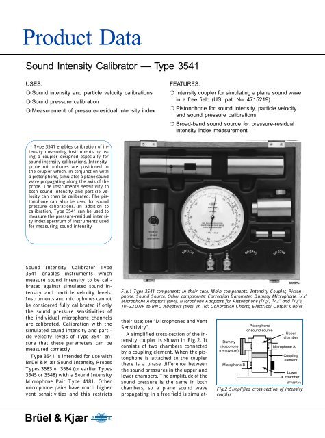
<strong>Product</strong> <strong>Data</strong><strong>Sound</strong> <strong>Intensity</strong> <strong>Calibrator</strong> — Type 3541USES:❍ <strong>Sound</strong> intensity and particle velocity calibrations❍ <strong>Sound</strong> pressure calibration❍ Measurement of pressure-residual intensity indexFEATURES:❍ <strong>Intensity</strong> coupler for simulating a plane sound wavein a free field (US. pat. No. 4715219)❍ Pistonphone for sound intensity, particle velocityand sound pressure calibrations❍ Broad-band sound source for pressure-residualintensity index measurementType 3541 enables calibration of intensitymeasuring instruments by usinga coupler designed especially forsound intensity calibrations. <strong>Intensity</strong>probemicrophones are positioned inthe coupler which, in conjunction witha pistonphone, simulates a plane soundwave propagating along the axis of theprobe. The instrument’s sensitivity toboth sound intensity and particle velocitycan then be calibrated. The pistonphonecan also be used for soundpressure calibrations. In addition tocalibration, Type 3541 can be used tomeasure the pressure-residual intensityindex spectrum of instruments usedfor measuring sound intensity.<strong>Sound</strong> <strong>Intensity</strong> <strong>Calibrator</strong> Type3541 enables instruments whichmeasure sound intensity to be calibratedagainst simulated sound intensityand particle velocity levels.Instruments and microphones cannotbe considered fully calibrated if onlythe sound pressure sensitivities ofthe individual microphone channelsare calibrated. Calibration with thesimulated sound intensity and particlevelocity levels of Type 3541 ensurethat these parameters can bemeasured correctly.Type 3541 is intended for use withBrüel & Kjær <strong>Sound</strong> <strong>Intensity</strong> ProbesTypes 3583 or 3584 (or earlier Types3545 or 3548) with a <strong>Sound</strong> <strong>Intensity</strong>Microphone Pair Type 4181. Othermicrophone pairs have much highervent sensitivities and this restrictsFig.1 Type 3541 <strong>com</strong>ponents in their case. Main <strong>com</strong>ponents: <strong>Intensity</strong> Coupler, Pistonphone,<strong>Sound</strong> Source. Other <strong>com</strong>ponents: Correction Barometer, Dummy Microphone, 1 / 4″Microphone Adaptors (two), Microphone Adaptors for Pistonphone ( 1 / 2 ″, 1 / 4 ″ and 1 / 8 ″),10–32 UNF to BNC Adaptors (two). In lid: Calibration Charts, Electrical Output Cablestheir use; see “Microphones and VentSensitivity”.A simplified cross-section of the intensitycoupler is shown in Fig. 2. Itconsists of two chambers connectedby a coupling element. When the pistonphoneis attached to the couplerthere is a phase difference betweenthe sound pressures in the upper andlower chambers. The amplitude of thesound pressure is the same in bothchambers, so a plane sound wavepropagating in a free field is simulat-Dummymicrophone(removable)Microphone BPistonphoneor sound sourceUpperchamberMicrophone ACouplingelementLowerchamber871887/1eFig.2 Simplified cross-section of intensitycouplerBrüel & Kjær BK
ed. If one microphone is positioned inthe upper chamber and the other inthe lower chamber, then the simulatedsound wave can be used for calibratingthe sensitivity of themeasuring instrument to sound intensityand particle velocity.The coupler and pistonphone canalso be used for calibration of soundpressure sensitivity. For this, the microphonesare both positioned in theupper chamber. Then they are exposedto exactly the same sound pressure(amplitude and phase).The broad-band sound source issupplied for measurement of the pressure-residualintensity index spectrum.This is used to assess theaccuracy of sound intensity measurements.A calibration chart is suppliedwhich states the levels that should bedetected during calibration. The chartalso gives information about correctionsto the calibration levels for usewhen conditions are different fromthe stated reference conditions. A correctionbarometer determines correctionterms to the sound pressure andparticle velocity calibration levels dueto changes in atmospheric pressure.The sound intensity calibration levelis independent of any change in atmosphericpressure.Calibration ProcedureFull calibration of an intensity measuringinstrument and its microphonesincludes:p AMicrophonesp BFig.3 Simplified block diagram of an intensity measuring instrument. The signals fromtwo pressure microphones, p A and p B , are used to determine the pressure at the midpointon the probe axis, p, and the particle velocity along the probe axis, u r . Multiplying pand u r gives the intensity reading I r . ∆ r is the microphone spacing and ρ is the densityof air❍ sound pressure calibration of theindividual microphone channels❍ sound intensity and particle velocitycalibration❍ measurement of the pressure-residualintensity index spectrum ofthe system.<strong>Sound</strong> pressure calibrationFig. 4 shows Pistonphone Type 4228fitted to the coupler, and both microphonespositioned in the upper chamberof the coupler. With thisarrangement, the pistonphone producesthe same sound pressure levelat each microphone. The microphonechannels are calibrated against thisknown sound pressure level.<strong>Sound</strong> intensity and particle velocitycalibrationsFig. 3 is a block diagram showing howsound intensity is measured. The+++−ΣΣp A + p Bp =2u r =p A − p Bdtρ∆ rXl r = p ⋅ u r871673/2eparticle velocity signal is obtained byintegrating, with respect to time, theinstantaneous difference in soundpressure between the two microphones.This signal is zero during asound pressure calibration, so thecorrect functioning of the instrumentis not confirmed.Fig. 5 shows the pistonphone fittedto the coupler, and the microphonespositioned in different chambers ofthe coupler. With this arrangement,the coupler causes a phase changebetween the sound pressures at themicrophones, corresponding to anominal spacing of 50 mm with noreflections. The phase change betweenthe sound pressures simulatesthe sound intensity and particle velocitylevels, so that the pressure-differencesignal for the integrator isnot zero. Only now is the correct functioningof the instrument confirmed.Fig.4 Arrangement for sound pressure calibrationFig.5 Arrangement for sound intensity andparticle velocity calibrationsFig.6 Arrangement for measuring residualintensity and pressure-residual intensityindex2
Residual <strong>Intensity</strong>1. A sound wave is incident on a probeaxis at 90°. There is no flow of acousticenergy along the probe axis. Thesignals from the microphones are inphase and no intensity is detected.2. If a sound wave is incident at an angleother than 90°, then acoustic energyflows along the probe axis. Themicrophone signals are out of phaseand intensity is detected.3. In practice, if a sound wave is incidentat 90°, then small differencesbetween the phase responses of themicrophones cause a small phase differencebetween the microphone signals.There now appears to be a flowof acoustic energy along the probe axis.4. It is this apparent flow of acousticenergy that is detected and called “residualintensity”.13Signalsare inphaseSignalsare notin phaseIdeal probe with nophase mismatch<strong>Intensity</strong>No intensity is detected870897/1eReal probe withphase mismatch<strong>Intensity</strong> is detected871837/1eEven under controlled laboratory conditions, it is very difficult to create a free-field situation where the angle between the propagationof the sound wave and the probe axis is exactly 90 degrees (as shown in boxes 1 and 3). However, for practical applications thissituation can easily be simulated using the set-up shown in Fig. 6.2Signalsare not inphase4dBIdeal probe with nophase mismatch<strong>Intensity</strong> is detectedSPLResidual intensityFrequency871838/1e870899/2ePressure-residual intensity indexmeasurementThe box at the top of the page showshow small differences in the phaseresponses of the microphones and inputchannels result in the detectionof “residual intensity”. Residual intensityis a parameter that should betaken into account when interpretingmeasured intensity data. It is worthnoticing that the residual intensityspectrum is not a fixed one; it is “tied”to, and rises and falls with, the measuredsound pressure level.Fig.6 shows an arrangement formeasuring pressure-residual intensityindex. The broad-band soundsource is fitted to the coupler and themicrophones are positioned in the upperchamber. The broad-band soundsource produces pink noise, so thesound pressure spectrum measuredin the coupler is constant (in octavebands) over a wide frequency range.Both microphones are exposed to thesame sound pressure, so any intensitydetected is residual intensity.It can be shown that, for a givenmeasurement system and frequency,the difference between measuredsound pressure level and detected residualintensity level will be a constant.This constant difference iscalled the pressure-residual intensityindex.The pressure-residual intensity indexspectrum can be measured withthe arrangement shown in Fig. 6 bysubtracting the detected intensityspectrum from the sound pressuredB706050403020100Fig.7 <strong>Intensity</strong> and sound pressure levels measured with the arrangement shown in Fig. 6.The pressure-residual intensity index spectrum is characteristic of the measurement systemand is obtained by subtracting these two spectradB605040302010Residual pressure - intensity index63 125 250 500 1k 2k 4k HzMeasured SPLSPL in coupler<strong>Intensity</strong> level in couplerResidual intensity levelMeasured intensity level63 125 250 500 1k 2k 4k Hz871670/2e871671/1eFig.8 <strong>Sound</strong> intensity and mean sound pressure spectra measured in the field with aninstrument calibrated with Type 3541. The residual intensity spectrum is obtained bysubtracting the pressure-residual intensity index spectrum in Fig. 7 from the measuredSPL spectrum3
spectrum. An example of this isshown in Fig. 7.Residual <strong>Intensity</strong> LevelIf a pressure-residual intensity indexspectrum is to be used to assess theaccuracy of sound intensity measurements,then the mean sound pressurespectrum in the field must also bemeasured. The residual intensity levelis then quickly established by subtractingthe pressure-residualintensity index spectrum from themeasured mean sound pressure spectrum.An example of this is shown inFig. 8.The residual intensity level is then<strong>com</strong>pared to the measured sound intensitylevel. It can be shown that,for a certain frequency, the residualintensity level must be at least 7 dBlower to ensure a measurement errorof less than 1 dB.The residual intensity level shownin Fig. 8 is dependent on the soundpressure level measured in the fieldand should not be confused with theintensity level which is measuredwith the arrangement shown inFig. 6.Microphones and VentSensitivityThe coupler, UA 0914, has been designedto work with Microphone PairType 4181 which have an extremelylow sensitivity to sound pressure attheir pressure-equalization vents.When microphones are inserted intothe coupler, their diaphragms are exposedto the sound pressure in thecoupler but their pressure-equalizationvents are not. Coupler UA 0914cannot be used to measure the pressure-residualintensity index withconventional microphone pairs asthey have vent sensitivities severalorders of magnitude higher than thatof Type 4181. It can, however, be usedwith conventional microphone pairsfor calibration of sound pressure,sound intensity, and particle velocity.4
Specifications Type 3541<strong>Intensity</strong> Coupler UA 0914FIRST CHAMBER: Ports 1 and 2SECOND CHAMBER: Port 3CHAMBER VOLUME: 10 cm 3 eachEQUIVALENT LOAD FOR EACH PORT:250 mm 3<strong>Sound</strong> Source ZI 0055ATTENUATION OF OUTPUT:0 to –10 dB (variable)BATTERY:1 × 9 V Alkaline Battery, type 6 LF 22 (QB 0016)Lifetime: 25 hours continuousELECTRICAL OUTPUT FROM INTERNALGENERATOR:Pink: 45 mV in each 1 / 3-octaveWhite: 45 mV in 250 Hz 1 / 3-octaveFREQUENCY RANGE: 10 Hz to 20 kHzOUTPUT IMPEDANCE: 50 ΩWhen the <strong>Sound</strong> Source, ZI 0055, is fitted to the<strong>Intensity</strong> Coupler, UA 0914, and driven from anexternal source the following specifications apply:SENSITIVITY:15.4 Pa/V (10 Hz to 1 kHz)MAXIMUM INPUT VOLTAGE: 70 mV RMSINPUT IMPEDANCE: >18kΩ (f 24dBDimension and Weight (Case)Height: 280 mm (11″)Width: 230 mm (9″)Depth: 63 mm (2.5″)Weight: 2.3 kg (5.1 lb)Note: All values are typical at 20°C (77°F), unlessmeasurement uncertainty or tolerance fieldis specified. All uncertainty values are specifiedat 2σ (i.e. expanded uncertainty using a coveragefactor of 2)EN 61010–1 and IEC 1010–1: Safety requirements for electrical equipment formeasurement, control and laboratory use.EN 50081–1: Generic emission standard. Part 1: Residential, <strong>com</strong>mercial andlight industry.EN 50081–2: Generic emission standard. Part 2: Industrial environment.CISPR 22: Radio disturbance characteristics of information technologyequipment. Class B Limits.FCC Rules, Part 15: Complies with the limits for a Class B digital device.EN 50082–1: Generic immunity standard. Part 1: Residential, <strong>com</strong>mercial andlight industry.EN 50082–2: Generic immunity standard. Part 2: Industrial environment.IEC68–2–1 & IEC68–2–2: Environmental Testing. Cold and Dry Heat.Operating Temperature: –10 to +50 °C (14 to 122 °F)Storage Temperature: –25 to +70 °C (–13 to 158 °F)IEC68–2–14: Change of Temperature: –10 to +50°C (2 cycles, 1 °C/min.)IEC68–2–3: Damp Heat: 90% RH (non-condensing at 40°C (104 °F))Ordering InformationType 3541 <strong>Sound</strong> <strong>Intensity</strong> <strong>Calibrator</strong>Includes the following accessories:UA 0914: <strong>Intensity</strong> CouplerType 4228: PistonphoneZI 0055: <strong>Sound</strong> SourceUZ 0004: Correction Barometer2 × UA 1314: Two 1 / 4″ Microphone AdaptorsDB 3111: <strong>Intensity</strong> Coupler Base-Plate6 × QB 0013: 1.5 V Alkaline Battery IEC TypeLR 6QB 0016: 9 V Alkaline Battery IEC Type6LF222×AO 0038: Cable with 10–32 UNFconnectors2 × JP 0145: 10–32 UNF to BNC Plug AdaptorUC 5298: Dummy MicrophoneMicrophone Adaptors for Pistonphone:DP 0776: 1 / 2″ AdaptorDP 0775: 1 / 4″ AdaptorDP 0774: 1 / 8″ AdaptorCalibration ChartsBrüel&Kjær reserves the right to change specifications and accessories without notice5
Brüel & Kjær BKWORLD HEADQUARTERS:DK-2850 Naerum · Denmark · Telephone: +45 45 80 05 00 · Fax: +45 45 80 14 05 · Internet: http://www.bk.dk · e-mail: info@bk.dkAustralia (02 ) 9450-2066 · Austria 00 43-1-865 74 00 · Belgium 016/44 92 25 · Brazil (011) 246-8166 · Canada: (514) 695-8225 · China 10 6841 9625 / 10 6843 7426Czech Republic 02-67 021100 · Finland 90-229 3021 · France (01) 69 90 69 00 · Germany 0610 3/908-5 · Holland (0)30 6039994 · Hong Kong 254 8 7486Hungary (1) 215 83 05 · Italy (02) 57 60 4141 · Japan 03-3779-8671 · Republic of Korea (02) 3473-0605 · Norway 66 90 4410 · Poland (0-22) 40 93 92 · Portugal (1) 47114 53Singapore (65) 275-8816 · Slovak Republic 07-37 6181 · Spain (91) 36810 00 · Sweden (08) 71127 30 · Switzerland 01/94 0 09 09 · Taiwan (02) 713 9303United Kingdom and Ireland (0181) 954-236 6 · USA 1 - 800 - 332 - 2040Local representatives and service organisations worldwideBP0703–13 96/03