Working & Maintenance Instructions - Varvel
Working & Maintenance Instructions - Varvel
Working & Maintenance Instructions - Varvel

You also want an ePaper? Increase the reach of your titles
YUMPU automatically turns print PDFs into web optimized ePapers that Google loves.
technology made in ItalyGB<strong>Working</strong> &<strong>Maintenance</strong><strong>Instructions</strong>
Technology Made in ItalySince 1955 <strong>Varvel</strong> has been making speed reducers andvariators for light industry applications. Reliable partner inpower transmission equipment offers also customized solutionsalways according to a socially responsible company values.Modularity and flexibility lead <strong>Varvel</strong> products by a unique kitform, common to all gearbox series. This feature allows distributorsan easier job to set up required products in few minutes.
WORKING INSTRUCTIONS& MAINTENANCERNRORVRDRCRGRTRSRPXAVR
<strong>Working</strong> <strong>Instructions</strong> & <strong>Maintenance</strong>Product LayoutElastic Coupling “G”The elastic coupling “G” is supplied as standard fitting on the Series RD, RN, RO, RV, RP, RS, RT.Reducer half-couplingMaterial: steel alloyOne piece built-in input shaftTwo bearing mountingUnchanged casing dimensionsSpiderExternal tooth connectionMaterial: Thermoplastic Elastomer- Elastollan ® TPU - Polyurethane- Hytrel ® TPE - PolyesterHardness- TPU 98 Shore A- TPE 72 Shore DTemperature- TPU -20/+75°C (-4 / +167°F)- TPE -30/+100°C (-22 / +212°F)Motor half-couplingMaterial:- Aluminium die cast (G3, G5, G6)- Alloy steel (GS8) Dynamic balancingFitting:- Clamp (G3, G5, G6)- Key (GS8)Bores:- IEC 72 / N42948- NEMA C y TCAdvantages: One gearbox only for each reduction ratio Greater flexibility Increased stock rotation Fretting corrosion elimination between key and keyway Zero backlash in gearbox/motor connection Allowed angular misalignment 1° max Torsional rigidity High vibration dampingInput flanges: Material:- Aluminium up to IEC112 and NEMA TC180- Cast iron from IEC 132 and NEMA TC200- 4 -
RC<strong>Working</strong> <strong>Instructions</strong> & <strong>Maintenance</strong>Product LayoutSeries RC - 2 stagesThe layout shows the general structure of a two-stage foot-mounted helical gearbox type FRC (sizes 05 to 30).01 Oil seal 19 Bearing02 Housing 20 Bearing03 Key 21 Pinion04 Output shaft 22 Key05 Key 23 Gear06 Bearing 24 Bearing07 Spacer 26 Bearing11 Gasket 27 Gear13 Bearing 29 IEC input cover15 Pinion 33 Hollow input16 Key 35 Oil seal17 Hollow input- 5 -
<strong>Working</strong> <strong>Instructions</strong> & <strong>Maintenance</strong>Product LayoutRDSeries RD - 2 stagesThe layout shows the general structure of a two-stage foot-mounted helical gearbox type FRD.01 Input cover 55 Spacer02 Hollow input 65 Bearing04 Pinion 66 Bearing15 Bearing 67 Bearing16 Bearing 68 Bearing20 Oil seal 69 Oil seal41 Gear 82 Gasket50 Housing 85 Motor Flange51 Upper cover52 Output shaft53 Pinion54 Gear- 6 -
RD<strong>Working</strong> <strong>Instructions</strong> & <strong>Maintenance</strong>Product LayoutSeries RD - 3 stagesThe layout shows the general structure of a three-stage foot-mounted helical gearbox type FRD.01 Input cover 41 Gear 69 Oil seal02 Hollow input 50 Housing 82 Gasket03 3rd stage shaft 51 Upper cover 85 Motor flange04 Pinion 52 Output shaft05 Gear 53 Pinion15 Bearing 54 Gear16 Bearing 55 Spacer17 Bearing 56 Spacer18 Bearing 65 Bearing19 Spacer 66 Bearing20 Oil seal 67 Bearing40 Pinion 68 Bearing- 7 -
<strong>Working</strong> <strong>Instructions</strong> & <strong>Maintenance</strong>Product LayoutRGSeries RG - 1 stageThe layout shows the general structure of a one-stage reduced backlash planetary gearbox type FRG.01 Screw 13 Sun gear02 Plug 14 Ring gear body03 Motor flange 15 Planet gear04 Screw 16 Needle bearing05 Input flange 17 Planet shaft06 Plug 18 Planet carrier07 Adapter 19 Key08 Clamp coupling 20 Bearing09 Bearing 21 Snap ring10 Input shaft 22 Shim11 Shim 23 Bearing12 Spacer 24 Snap ring- 8 -
RG<strong>Working</strong> <strong>Instructions</strong> & <strong>Maintenance</strong>Product LayoutSeries RG - 2 stagesThe layout shows the general structure of a two-stage reduced backlash planetary gearbox type FRG.01 Screw 13 Sun gear 25 Bearing02 Plug 14 Ring gear body 26 Snap ring03 Motor flange 15 Planet gear 27 Shim04 Screw 16 Needle bearing 28 Bearing05 Input flange 17 Planet shaft 29 Snap ring06 Plug 18 Planet carrier07 Adapter 19 Planet gear08 Clamp coupling 20 Needle bearing09 Bearing 21 Planet shaft10 Input shaft 22 Spacer11 Shim 23 Planet carrier12 Spacer 24 Key- 9 -
<strong>Working</strong> <strong>Instructions</strong> & <strong>Maintenance</strong>Product LayoutRNSeries RN - 2 stagesThe layout shows the general structure of a two-stage parallel shaft gearbox type FRN with through hollow output shaft.01 Input flange 13 Bearing 25 Spacer02 Oil seal 14 Key 26 Bearing03 Snap ring 15 Pinion 27 Snap ring04 Bearing 16 Bearing 28 Oil seal05 Input shaft 17 Snap ring06 Bearing 18 Oil seal07 Cover 19 Snap ring08 Pinion 20 Bearing09 Oil seal RCA 21 Body10 Snap ring 22 Key11 Gear 23 Output shaft12 Spacer 24 Gear- 10 -
RN<strong>Working</strong> <strong>Instructions</strong> & <strong>Maintenance</strong>Product LayoutSeries RN - 3 stagesThe layout shows the general structure of a three-stage parallel shaft gearbox type FRN with through hollow output shaft.01 Motor flange 13 Shaft 25 Snap ring02 Oil seal 14 Bearing 26 Oil seal03 Snap ring 15 Snap ring 27 Snap ring04 Bearing 16 Pinion 28 Bearing05 Input shaft 17 Oil seal RCA 29 Spacer06 Bearing 18 Snap ring 30 Gear07 Pinion 19 Bearing 31 Output shaft08 Cover 20 Pinion 32 Key09 Bearing 21 Key 33 Body10 Gear 22 Bearing 34 Bearing11 Spacer 23 Spacer 35 Snap ring12 Key 24 Gear 36 Oil seal- 11 -
<strong>Working</strong> <strong>Instructions</strong> & <strong>Maintenance</strong>Product LayoutROSeries ROThe layout shows the general structure of a three-stage bevel/helical gearbox type FRO with through hollow output shaft.01 Motor flange 13 Gear 25 Output shaft02 Oil seal 14 Spacer 26 Body03 Snap ring 15 Bearing 27 Snap ring04 Input shaft 16 Cover 28 Bearing05 Bearing 17 Pinion 29 Pinion06 Pinion 18 Oil seal RCA 31 Bearing07 Oil seal RCA 19 Oil seal 32 Spacer08 Snap ring 20 Snap ring 33 Gear09 Bearing 21 Bearing 34 Snap ring10 Key 22 Spacer 35 Bearing11 Shaft 23 Gear 36 Snap ring12 Spacer 24 Key 37 Oil seal- 12 -
RV<strong>Working</strong> <strong>Instructions</strong> & <strong>Maintenance</strong>Product LayoutSeries RVThe layout shows the general structure of a three-stage bevel/helical gearbox type FRV with through hollow output shaft.01 Motor flange 13 Bearing 25 Bearing02 Oil seal 14 Shaft 26 Snap ring03 Snap ring 15 Key 27 Oil seal04 Input shaft 16 Bearing 28 Snap ring05 Bearing 17 Snap ring 29 Bearing06 Pinion 18 Oil seal RCA 30 Body07 Oil seal RCA 19 Snap ring 31 Output shaft08 Pinion 20 Gear 33 Gear09 Cover 21 Spacer 34 Spacer10 Bearing 22 Bearing 35 Bearing11 Spacer 23 Key 36 Snap ring12 Gear 24 Pinion 37 Oil seal- 13 -
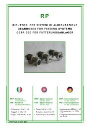
<strong>Working</strong> <strong>Instructions</strong> & <strong>Maintenance</strong>Product LayoutRP & XASeries RP and XAThe layout shows the general structure of a one-stage helical gearbox type FRP and FXA, flange mounting.FXAFRP9001 Body 15 Bearing02 Snap ring 16 Bearing03 Oil seal 18 Snap ring04 Output shaft 19 Bearing05 Key 20 Key06 Screw 21 Adapter07 Bearing 24 Snap ring08 Gear 25 Spacer10 Motor flange 26 Plug11 Snap ring 27 Flexible coupling12 Oil seal13 Pinion- 14 -
RS<strong>Working</strong> <strong>Instructions</strong> & <strong>Maintenance</strong>Product LayoutSeries RSThe layout shows the general structure of a worm gearbox type FRS with through hollow output shaft and shaft mounting.The Series TA (helical / worm) are made of a helical one-stage gearbox XA mounted as input stage onto a standard wormbox RS and the Series RS/RS (two stage worm) of two standard worm boxes RS and an appropriate combination kit.01 Body 84 Oil seal RCA04 Side cover 125 Snap ring07 Motor flange 126 Snap ring31 Worm wheel50 Worm shaft60 Bearing61 Bearing62 Bearing63 Bearing80 Oil seal81 Oil seal82 Oil seal- 15 -
<strong>Working</strong> <strong>Instructions</strong> & <strong>Maintenance</strong>Product LayoutRTSeries RTThe layout shows the general structure of a foot-mounted worm gearbox type FRT.The Series TA (helical / worm) are made of a helical one-stage gearbox XA mounted as input stage onto a standard wormbox RT and the Series RT/RT (two stage worm) of two standard worm boxes RT and an appropriate combination kit.01 Housing 84 Oil seal RCA04 Side cover 125 Seeger ring07 Motor flange 126 Seeger ring31 Worm wheel50 Worm shaft60 Bearing61 Bearing62 Bearing63 Bearing80 Oil seal81 Oil seal82 Oil seal- 16 -
TLE<strong>Working</strong> <strong>Instructions</strong> & <strong>Maintenance</strong>Product LayoutTLE - Torque Limiter OptionThe layout shows the general structure of a torque limiter type TLE to fit inside a worm gearbox Series RS or RT.The Torque Limiter TLE is directly fitted into the hollow shaft of already assembled standard gearboxes withoutany special tooling.RTRS01 Setting torque hand wheel 13 Front washer02 Belville washer 14 Front friction03 Spacer 15 Front protection04 Spacer 16 Front bush05 Rear protection 17 Key06 Belville washer 18 Low speed shaft07 Key08 Thrust washer09 Rear friction10 Rear washer11 Key12 Rear bush- 17 -
<strong>Working</strong> <strong>Instructions</strong> & <strong>Maintenance</strong>Product LayoutTLITLI - Torque Limiter OptionThe layout shows the general structure of a built-in torque limiter type TLI incorporated inside a worm gearbox Series RSor RT.RTRS01 Lock nut 81 Oil seal02 Bellville washer03 Bush04 Oil seal05 Key06 Spacer07 Worm wheel08 Hollow output shaft10 Cover60 Bearing61 Bearing80 Oil seal- 18 -
VR<strong>Working</strong> <strong>Instructions</strong> & <strong>Maintenance</strong>Product LayoutSeries VRThe layout shows the general structure of a flange-mounted variator without gearbox type.01 Screw 14 Control hand wheel 27 Spacer02 IEC motor flange 15 Control shaft lock 28 Bearing03 Screw 16 Control shaft 29 Snap ring04 Seal plate 17 Oil seal OR 30 Oil seal05 Bearing 18 Screw 31 Index scale06 Spacer 19 Output shaft 32 Snap ring07 Cone 20 Key 33 Spring09 Body 21 Bearing 34 Friction ring carrier10 Cylindrical slide 22 Snap ring 35 Friction ring11 Oil seal OR 23 Snap ring 39 Cone holder12 Oil seal OR 24 Oil seal 40 Bellows seal13 Screw 26 Output flange 41 Index- 19 -
<strong>Working</strong> <strong>Instructions</strong> & <strong>Maintenance</strong>Product LayoutVSSeries VSThe layout shows the general structure of a flange-mounted variator without gearbox type.01 Output shaft02 Planet carrier03 Sliding bush04 Adjusting track05 Ball carrier06 External mobile track07 Planet08 Adjusting box09 External fixed track10 Internal fixed track11 Internal mobile track12 Belville washer- 20 -
<strong>Working</strong> <strong>Instructions</strong> & <strong>Maintenance</strong>InstallationINSTALLATION4.1 TolerancesTolerances are recommended according to DIN 748 as follows Shafts:solid input or output ISO h6hollow input ISO E8hollow output ISO EH7centre hole DIN 332, DR Flanges: spigot ISO h74.2 PrecautionsCheck that the unit to be put into service is rightly sized to perform the required function and that its mounting positioncomplies with the order. Such data are shown in the nameplate fitted on the unit.Check mounting stability so that the unit operates without vibrations or overloads, or insert damping couplings or torquelimiters.Care must be taken to ensure exact positioning and steadiness when handling the units to not origin damages to normaloperation of the unit.When hoisting, use relevant locations of the housing or eyebolts if provided, or foot or flange holes.Never hoist on any moving part (input or out-put shafts).4.3 GroundworkClean carefully all the surfaces of shafts and flanges paying attention that the used product for cleaning does not came incontact with sealing lips of oil seals to avoid any damage and lubricant leakages.4.4 Set upThe unit may be connected for clockwise or counter-clockwise rotation.Stop immediately the unit when unexpected running or noise occurs: if the part originating the anomaly is not identified,other parts may be damaged with consequent difficulty in going back to the cause.4.5 Pulleys, Pinions, CouplingsBore tolerance F7 is recommended when fitting pulleys, pinions, couplings, etc. on the output shaft.It is also recommended to not fit or extract with mallets or hammer hits to not damaging internal parts, but to use the shaftheadthreaded bore as reaction to fitting or extraction. Belt drives: the force imposed on the shaft due to belt tension to not exceed the maximum permissible radial force ofthe unit. Chain drives: properly lubricate the chain drive and check that no pitch differences hinder its smooth running.4.6 Torque armThe torque arm Type BR (Series RS) or Type BT (Series RT) can rotate by 45° within the arc 45° to 315°.The types BRV (Series RS) and Type BTV (Series RT) incorporate a Vulkollan® bush to allow vibration dumping.4.7 PaintingCarefully protect oil seals, coupling faces and shafts when re-painting the units.- 21 -
<strong>Working</strong> <strong>Instructions</strong> & <strong>Maintenance</strong>Starting - Inspections and <strong>Maintenance</strong>5 STARTING5.1 Series RS, RTThe worm gearbox originates the following rotations of input and output shafts, with worm shaft upwards : inverse rotationone-stage gearboxes (RS, RT); original rotationhelical/worm gearboxes (RA, TA); inverse rotationtwo-stage gearboxes (RS/RS, RT/RT).Worm shaft downwards: opposite rotations.5.2 Series RC, RD, RN, RO/RV, RP, XA, VR, VSThe helical or bevel/helical gearbox and the variator originate the following rotations of input and output shafts : inverse rotationodd-stage gearboxes (one, three, etc.)and variators with odd-stages ; original rotationeven-stage gearboxes (two, four, etc.)and variators without stages or even-stages .6 INSPECTIONS AND MAINTENANCE6.1 IntervalsAlthough the units are no-load run tested in the factory before despatch, it is advisable not to run them at maximum loadfor the first 20-30 hours to allow proper running in.For variators, run throughout the full speed range at reduced load before the full load is applied.The units are delivered already filled with synthetic long-life oil: no servicing or refilling within the average lifetime of15,000 hours for operation according to SF1.0.Refer to the Catalogues as appropriate to the right definition of Service Factor.Variators Series VR run dry and bearings are lifetime grease packed; therefore, there is no part needing periodicalmaintenance, the friction ring replacement excepted on normal wearing conditions. .6.2 <strong>Maintenance</strong> ServicingUnits supplied without any oil plugs:Series RC (sizes 05, 10, 20, 30)Series RD (sizes 0, 1, 2, 3, 4)Series RG (sizes 05, 07, 09, 12)Series RN (sizes 1, 2, 3, 4, 5, 6)Series RO (sizes 1, 2, 3, 4, 5, 6)Series RV (sizes 1, 2, 3, 4, 5, 6)Series RP (size 71)Series RS (sizes 28, 40, 50, 60, 70, 85)Series RT (sizes 28, 40, 50, 60, 70, 85, 110)Series XA (sizes 63, 71, 80, 100)Series VR (sizes 63, 71, 80, 90)- 22 -
<strong>Working</strong> <strong>Instructions</strong> & <strong>Maintenance</strong>Inspections and <strong>Maintenance</strong>6 INSPECTIONS AND MAINTENANCE (contd)6.2 <strong>Maintenance</strong> ServicingUnits supplied with oil plugs:Series RC (sizes 40, 50, 60)Series RS (sizes 110, 130, 150)Series VS (sizes 63, 71, 80, 90, 100, 112)Periodically check the seal condition and possible evidence of lubricant leakages.If lubricant replacement or topping is required, do not mix synthetic lubricants with mineral based lubricants.According to working conditions:Eliminate by means of a vacuum cleaner any dust accumulation thicker than 5 mm. GEARBOXES Every 500 working hours or every month:Oil seal visual check to monitoring any lubricant leakage. Every 3000 working hours or every 6 months:Oil seal check and replacement if considerably used. Every 5 years:Replace synthetic oil.VARIATORS - Series VR onlySeries VRVariation section, dry running and with lifetime grease-packed bearings, does not require any periodic servicing, exceptedthe friction ring replacement on normal wearing conditions. According to working conditions:Replace friction ring, if considerably used. Every 3000 working hours or every 6 months:Check output shaft angular play and oil seal and corrugated hood integrity. Every 6000 working hours or every year:Replace friction ring.Series VSVariation section, mineral oil lubricated, requires periodic servicing as follows: Every 500 working hours or every month:Oil seal visual check to monitoring any lubricant leakage. Every 3000 working hours or every 6 months:Oil seal check and replacement if considerably used. Every 5 years:Replace mineral oil .- 23 -
<strong>Working</strong> <strong>Instructions</strong> & <strong>Maintenance</strong>Malfunctioning7 MALFUNCTIONING7.1 Major Events Running noise, continuous Grinding sound: damaged bearing .Replace bearing & check the oil Knocking sound: irregular gearingContact Customer Service Running noise, intermittent Foreign particles in the oilContact Customer Service Series VR - Damaged friction ringRectify the cause and replace friction ring.See the next Section «Friction Ring Replacement» Oil leakages(see also next note) Damaged oil sealReplace the oil seal Loosen screwsTighten the screws Inner overpressureContact Customer ServiceOil seal fittingDefective fitting or fitting-lubricant melting No rotation of output shaft Internal connection cut offContact Customer Service Series VR - Friction ring end of lifeReplace the friction ringSee the next Section «Friction Ring Replacement» Series VR - Contaminated friction ringClean carefully cone and ring working areas with solvent of similarproduct .See the next Section «Friction Ring Replacement»7.2 Customer ServiceWe recommend to always provide the Customer Service with the following information: Full data of name plate and/or Serial No. Type of application Duty cycle Circumstances of malfunctioning Supposed causes.- 24 -
<strong>Working</strong> <strong>Instructions</strong> & <strong>Maintenance</strong>Lubricants8 LUBRICANTS8.1 Recommended TypesAll the units are delivered already filled with synthetic long-life oil.The safe operation of the units with ISO VG 320 grade lubricant is recommended in the ambient temperature range-20 to +55 °C (-4 to 131 °F)Other temperatures require specific recommendations for low or high temperatures to ask the Customer Service.Temperature rangeISOVG* 320DegolGS 320EnersynSG-XP320AlphasynPG 320Glycolube320GlygoyleHE 320SynlubeCLP 320CarterSY 320TivelaSC 320** 320EuralGear 320---VitalubeGS 320Gear OilFM 320Mobil DTEFM 320---NevastaneEP320CassidaFluidGL 320* - Synthetic Oil** - Food Industry Oil8.2 Quantity [litres]RC 1c l 1 l 2 l 3 2c l 1 l 2 l 3 3c l 1 l 2 l 3RC105 0.05 0.65 0.05 RC205 0.13 0.15 0.15 RC305 0.17 0.30 0.30RC110 0.10 0.13 0.10 RC210 0.17 0.25 0.17 RC310 0.25 0.50 0.35RC120 0.17 0.25 0.17 RC220 0.50 0.60 0.50 RC320 0.60 0.80 0.60RC130 0.30 0.50 0.30 RC230 0.70 1.15 0.80 RC330 1.15 1.50 1.15RC140 0.60 1.15 0.60 RC240 1.15 2.25 2.00 RC340 1.50 3.00 2.25RC150 1.50 2.25 1.50 RC250 2.25 4.40 4.00 RC350 3.75 6.00 5.00RC160 3.00 4.40 3.00 RC260 6.00 8.80 8.00 RC360 8.00 10.00 8.801c - One stage 2c - Two stages 3c - Three stagesl 1 - B3, B6, B7, B8, B5 l 2 - V1, V5 l 3 - V3, V6RD 2c H V 3c H VRD02 0.20 0.28 RD03 0.30 0.38RD12 0.50 0.70 RD13 0.50 0.70RD22 0.80 1.00 RD23 0.80 1.00RD32 1.30 1.80 RD33 1.60 2.10RD42 2.20 3.00 RD43 2.20 3.40RD52 4.50 5.50 RD53 4.50 6,.50RD62 7.00 9.00 RD63 7.00 11.002c - Two stagesH = H1, H2, H3, H4V = V5, V63c - Three stages- 25 -
<strong>Working</strong> <strong>Instructions</strong> & <strong>Maintenance</strong>Lubricants8.2 Quantity [litres] (contd)RP FRP l71 0.05RS RS l RA l 1 / l 2 RS / RS l 3 / l 428 0.03 63 / 40 0.04 / 0.08 28 / 28 0.03 / 0.0340 0.08 63 / 50 0.04 / 0.13 28 / 40 0.03 / 0.1050 0.13 63 / 60 0.04 / 0.20 28 / 50 0.03 / 0.1560 0.20 71 / 50 0.06 / 0.13 28 / 60 0.03 / 0.2570 0.35 71 / 60 0.06 / 0.20 40 / 70 0.10 / 0.3585 0.60 71 / 70 0.06 / 0.35 40 / 85 0.10 / 0.63110 1.50 71 / 85 0.06 / 0.60 50 / 110 0.15 / 1.50130 2.75 80 / 60 0.10 / 0.20 60 / 130 0.25 / 2.75150 4.40 80 / 70 0.10 / 0.35 70 / 150 0.35 / 4.4080 / 85 0.10 / 0.6080 / 110 0.10 / 1.50100 / 110 0.20 / 1.50100 / 130 0.20 / 2.75100 / 150 0.20 / 4.40l - Litres FRS l 1 / l 2 - Litres FXA / FRS l 3 / l 4 - Litres FRS / FRSRT RT l TA l 1 / l 2 RT / RT l 3 / l 428 0.03 63 / 40 0.04 / 0.08 28 / 28 0.03 / 0.0340 0.08 63 / 50 0.04 / 0.13 28 / 40 0.03 / 0.0850 0.13 63 / 60 0.04 / 0.20 28 / 50 0.03 / 0.1360 0.20 71 / 50 0.06 / 0.13 28 / 60 0.03 / 0.2070 0.35 71 / 60 0.06 / 0.20 40 / 70 0.08 / 0.3585 0.60 71 / 70 0.06 / 0.35 40 / 85 0.08 / 0.60110 1.50 71 / 85 0.06 / 0.60 50 / 110 0.13 / 1.5080 / 60 0.10 / 0.2080 / 70 0.10 / 0.3580 / 85 0.10 / 0.6080 / 110 0.10 / 1.50100 / 110 0.20 / 1.50l - Litres FRT l 1 / l 2 - Litres FTA / FRT l 3 / l 4 - Litres FRT / FRTXA FXA l63 0.0471 0.0680 0.10100 0.20- 26 -
<strong>Working</strong> <strong>Instructions</strong> & <strong>Maintenance</strong>Lubricants8.2 Quantity [litres] (contd)RN RN-2 H1 [ l ] H2 [ l ] H3 [ l ] H4 [ l ] V1 [ l ] V2 [ l ] RN-3 H1 [ l ] H2 [ l ] H3 [ l ] H4 [ l ] V1 [ l ] V2 [ l ]12 0.5 0.6 0.4 0.6 0.6 0.6 13 0.5 0.4 0.3 0.4 0.6 0.422 0.6 0.7 0.5 0.7 0.7 0.7 23 0.6 0.5 0.4 0.5 0.7 0.532 1.1 1.3 0.8 1.3 1.2 1.2 33 1.2 1.0 0.6 1.0 1.2 1.042 2.8 1.8 1.2 1.8 2.7 2.7 43 2.5 1.5 0.9 1.5 2.2 1.952 5.1 3.2 2.1 3.2 4.9 4.9 53 5.0 2.8 1.6 2.8 4.0 3.462 9.2 5.8 3.8 5.8 8.8 8.8 63 9.0 5.0 2.9 5.0 7.2 6.1RORVRO H1 [ l ] H2 [ l ] H3 [ l ] H4 [ l ] V1 [ l ] V2 [ l ] RV H1 [ l ] H2 [ l ] H3 [ l ] H4 [ l ] V1 [ l ] V2 [ l ]13 0.6 0.6 0.6 0.6 0.7 0.7 13 0.6 0.5 0.4 0.5 0.6 0.623 0.9 0.7 0.9 0.7 1.0 1.0 23 0.9 0.6 0.5 0.6 0.7 0.733 1.5 1.2 1.4 1.2 1.7 1.7 33 1.5 1.0 0.8 1.0 1.2 1.243 2.8 2.0 1.6 2.0 2.5 2.5 43 2.9 1.9 1.2 1.8 2.6 2.653 5.1 3.6 2.9 3.6 5.0 5.0 53 5.2 3.4 2.1 3.2 4.7 4.763 9.2 6.5 5.2 6.5 9.0 9.0 63 9.4 6.1 3.8 5.8 8.5 8.5RGLow backlash planetary gearboxes are Kluber Synth GE 46 life-greased.- 27 -
<strong>Working</strong> <strong>Instructions</strong> & <strong>Maintenance</strong>Directive 94/9 CE (ATEX)9 DIRECTIVE 94/9/CE - ATEX9.1 General Information ............................................................................................................................................ 289.2 Prevalent Use ...................................................................................................................................................... 289.3 References ........................................................................................................................................................... 289.4 Temperature ........................................................................................................................................................ 299.5 Safety <strong>Instructions</strong> .............................................................................................................................................. 299.6 ATEX Marking ...................................................................................................................................................... 299.7 <strong>Maintenance</strong> Servicing ....................................................................................................................................... 309.8 Materials - Dangerous Zones - Categories ........................................................................................................ 309.9 Temperature Class for Gas ................................................................................................................................ 31CERTIFICATE OF CONFORMITY ............................................................................................................................... 329.1 General InformationDirective relates not only to electrical equipment, but also to all kind of machines and control components, separately orjointly, for use in potentially explosive atmospheres.The following recommendations, issued to operations in potentially explosive environment, are meant as specific completionto the preceding «<strong>Working</strong> <strong>Instructions</strong>».VARVEL-ATEX gearboxes are manufactured with housings and covers of metallic material, incorporating the transmissionelements fitted on ball and roller bearings, with Viton oil seals on input and output shafts et with the adequate oilquantity to assure the design operation.9.2 Prevalent UseVARVEL-ATEX gearboxes are identified as « components », fundamental but without any autonomous function to operateunits and protection systems for production, transport, storage, measurement, control and conversion of energy, orthe processing of materials which are capable of causing an explosion through their own potential source of ignition.9.3 ReferencesVARVEL-ATEX gearboxes are designed and produced according to Directive 94/9/CE and the following standards EN 1127-1 - Explosion prevention and explosion protection,Fundamental notions and methodology. EN 13463-1 - Not electrical devices for potentially explosive atmospheres,Basic methods and required conditions. EN 13463-5 - Not electrical devices for potentially explosive atmospheres,Section 5: protection by construction safety « c ». EN 13463-6 - Not electrical devices for potentially explosive atmospheres,Section 6: protection by trigger source control « b ». EN 13463-8 - Not electrical devices for potentially explosive atmospheres,Section 8: protection by construction safety « k ».- 28 -
<strong>Working</strong> <strong>Instructions</strong> & <strong>Maintenance</strong>Directive 94/9 CE (ATEX)9.4 TemperatureThe units must be properly ventilated: check that ventilation temperaturedoes not exceed 55 °C.Measure housing temperature after 2 hours from start up andcheck that the difference between measured temperature(see sketch) and ambient temperature does not exceed themax. value of 80 °C.In such a case, immediately stop the unit and call for CustomerService.9.5 Safety <strong>Instructions</strong>Electric motors and other elements to fit at the input or at the output of VARVEL-ATEX products, must be ATEX approvedaccording the Directive 94/9/CE.Expected temperature limits of the products must comply with temperature classes and max. temperature.VARVEL gearboxes must be installed and serviced according to installation and servicing standards for classified environmentsagainst explosion hazard because of gas or dust presence (e.g. EN 60079-14, EN 60079-17, EN 50281-1-2 andany other acknowledged national standard).In case of combustible dusts, it is mandatory the regular cleaning to avoid any accumulation of dust layers on product surfaces.9.6 ATEX MarkingVARVEL Series RC, RD, RP, RS, RT, XA conform to design requirements required by Group II, Category 2 and to operatein areas with explosion danger of gas (Zone 1 and Zone 2) and combustive dust (Zone 21 and Zone 22).- Dust accumulation: max. thickness on sur-face 5 mm maximum (EN50281-1-2)- Casing: IP66 (Ingress Protection)VARVEL-ATEX products are identified by the corresponding technical files, deposited at the Notified Body of TechnicalFile Deposit, INERIS - France:- Series RC “ATEX 03RC” - Series RD “ATEX 03RD” - Series RP “ATEX 03RP”- Series RT “ATEX 03RT” - Series RS “ATEX 03RS” - Series XA “ATEX 03XA”and markedII 2 GD ck IP66T max =120°C orT max =135°C T amb -20/+55 °Cwhere:II- Group II (Surface Industries)2 - Category 2G- Explosive atmosphere with presence of gas, vapours or cloudsZone1 (2G) and Zone 2 (2G o 3G)D- Explosive atmosphere with presence of dustZone 21 (2D) and Zone 22 (2D o 3D)b - Trigger Source Control « b »c - Construction Safety « c »k - Liquid Dipping « k »IP66- Protection Grade (Ingress Protection)T max- Max. Surface TemperatureT amb- Ambient TemperatureATEX 03XX - Technical File Ref. No.- 29 -
<strong>Working</strong> <strong>Instructions</strong> & <strong>Maintenance</strong>Directive 94/9 CE (ATEX)9.7 <strong>Maintenance</strong> ServicingStrict observance of maintenance intervals is recommended to ensure appropriate working conditions and explosion-proofprotection.According to working conditions:Elimination of any dust accumulation thicker than 5 mm by means of a vacuum cleaner.Every 500 working hours or every month:Visual inspection of oil seals to monitor any lubricant leakage.Every 3000 working hours or every 6 months:Inspection of oil seals and replacement if worn-out.Every 5 years:Replacement of synthetic oil.9.8 Materials - Dangerous Zones - CategoriesCORRESPONDENCE AMONG MATERIALS, DANGEROUS ZONES AND CATEGORIES(ACCORDING TO DIRECTIVE 94/9/CE)MATERIALS DANGEROUS ZONES CATEGORIESGasVapourCloudZone 01GZone 1 1G 2GZone 2 1G 2G 3GZone 201DDustZone 21 1D 2DZone 22 1D 2D 3DVARVEL-ATEX Products to not supply- 30 -
<strong>Working</strong> <strong>Instructions</strong> & <strong>Maintenance</strong>Directive 94/9 CE (ATEX)9.9 Gas Temperature ClassGAS TEMPERATURE CLASSGROUP T1 T2 T3 T4 T5 T6I*Natural gas(Firedamp)II AEthyl acetateMethyl acetateAcetoneAmmoniaBenzeneBenzolChlorine methyleneChlorine ethyleneEthaneMethaneMethanolCarbon monoxideNaphtalenePropaneTolueneXyleneButyl acetatePropyl acetateAmyl alcoholEthyl alcoholIsobutyl alcoholMethyl alcoholn-butyl alcoholAcetic anhydrideCiclohexanoneLiquefied petroleumgasNatural gasIso-PropaneMono amyl acetaten-ButaneCyclohexaneCyclohexanolDecaneHeptaneHexaneGasoilKeroseneNaphthaPentaneOil **acetaldehydeEthylic etherII BCoke gasWater gas1.3-butadieneEthyl benzeneEthyleneEthylene oxideSulphydric acidIsopreneOil **Ethylic etherII C Hydrogen Acetylene Ethyl nitratecarbon sulphide* - VARVEL-ATEX Products to not supply** - According to chemical composition- 31 -
<strong>Working</strong> <strong>Instructions</strong> & <strong>Maintenance</strong>Conformity Certificate (specimen)VARVEL SpaVia 2 Agosto 1980. 940056 Crespellano BOItalydichiara sotto la propria responsabilità che il prodottodeclares on his own responsibility that the productRiduttoriGearboxesSerie/s RSSerie/s RTSerie/s RDSerie/s RCSerie/s RPSerie/s XAal quale questa dichiarazione si riferisce, è conformealla Direttivato which this declaration relates to, complies withthe Directive94/9/EC (ATEX).La conformità è stata verificata sulla base dei requisitidelle norme o dei documenti normativiThe conformity is under observance of the standarddocumentsEN 1127-1EN 13463-1EN 13463-5EN 13463-8Modo di protezione:Type of protection:II 2 GD ck IP66Tmax = 120°C oppure/orTmax = 135°C Tamb. -20/+55°CI File TecniciThe Technical Filessono stati depositati presso l’Organismo Notificatodi deposito del fascicolo tecnicowere deposited at the Notified Body of TechnicalFile DepositATEX 03RS, ATEX 03RT, ATEX 03RC,ATEX 03RD, ATEX 03RP, ATEX 03XA0080 INERIS,F-60550 Verneuil en Halatte, FranceFirma autorizzata(Funzione: Presidente)Authorized Signature(Function: President)VARVEL SpaLuogo e data dell’emissionePlace and Date of IssueCrespellano, ../../....C-IUM ed01-2011 rev01 GB 211112.pub- 32 -
unicefA socially responsible companyTo the scope of intensifying our commitment to society, <strong>Varvel</strong>since 2004 started an ongoing support programme with threenon-profit institutions: UNICEF (United Nations Children'sFund), MSF (Médicins sans Frontères) and ANT (NationalCancer Association). Environmental respect and protection arealso part of <strong>Varvel</strong>’s values and this is why <strong>Varvel</strong> certified in 2001its Environmental System to standard UNI EN ISO 14001.
<strong>Varvel</strong> SpAVia 2 Agosto 1980, 940056 Crespellano (BO) Italy +39 051 6721811+39 051 6721825varvel@varvel.comwww.varvel.comGB