ANT-Hy-Gain-AV-18AVQ..
ANT-Hy-Gain-AV-18AVQ..
ANT-Hy-Gain-AV-18AVQ..

You also want an ePaper? Increase the reach of your titles
YUMPU automatically turns print PDFs into web optimized ePapers that Google loves.
Model 18<strong>AV</strong>QIIFive Band Vertical Antenna10, 15, 20, 40, 80 Meter308 Industrial Park RoadStarkville, MS 39759(662) 323-9538 Fax: (662) 323-5803INSTRUCTION MANUALGeneral DescriptionThe <strong>Hy</strong>-<strong>Gain</strong> 18<strong>AV</strong>QII is an omni-directional, vertical radiator that operates on the 10,15, 20, 40, and 80 meter amateur bands. The system will work against earth ground or aresonant radial system when mounted above ground. You can make your own radialsystem following the manual, or use the <strong>Hy</strong>-<strong>Gain</strong> 14RMQ Radial System Kit available atyour <strong>Hy</strong>-<strong>Gain</strong> dealer.The antenna can be used for either Phone or CW with either a ground or roof mount. Itcan also be tuned to mid-band for use with either Phone or CW. In either case, the SWRbandwidths of the antenna are broad enough that the antenna will operate at an SWR of2:1 or less on the 10, 15, 20, and 40 meter bands. The antenna will radiate on the 80meter band with a limited bandwidth. The 18<strong>AV</strong>QII is supplied with stainless steelhardware and element clamps for all electrical and most mechanical connections.Theory of OperationThe use of heavy duty "<strong>Hy</strong>-Q Traps" provides automatic band selection. The <strong>Hy</strong>-Q Trapsare parallel resonant circuits which isolate the various sections of the antenna and givequarter wavelength resonance on all bands. The top loading coil is used for operation onthe 80 meter band while the overall height of the antenna remains less than 20 feet.WARNING: When installing your antenna, take extreme care to avoid any accidentalcontact with power lines or overhead obstructions. Failure to exercise this care couldresult in serious or fatal injury.NOTE: If the terminals of the input connector are checked with an ohmmeter, they willshow a direct short. This is normal! The matching coil in the antenna base puts the entiresystem at DC ground, but presents a 50 ohm load impedance to RF energy.Choosing a SiteThe 18<strong>AV</strong>QII can be mounted on the ground, on a rooftop, or on a mast. The antennashould be secured using non-conducting guy ropes if the 80 meter loading coil isinstalled. When choosing an installation site be sure to allow sufficient space for theseguy ropes.
Radial System and GroundingWhen mounting the antenna more than three feet above ground, a resonant radial systemmust be used, such as <strong>Hy</strong>-<strong>Gain</strong>'s 14RMQ Radial System Kit. If the antenna is roofmounted and the roof space is too small for a radial system, you can droop the radialsover the edge of the roof at almost any angle without seriously changing the performanceof the antenna. The radial system must be insulated from the roof and connected to agood ground or lightning protection. See Figure 5. For best performance, the 18<strong>AV</strong>QIIshould be ground-mounted clear of building and other structures. When the antenna isground-mounted, a radial system is sometimes not needed. In most areas, where soilsurface conductivity is poor and a good ground plane is not possible, lay out groundradials to improve the efficiency of your antenna.Installation of RadialsThere is no need to make radials exactly ¼ wavelength long for the 18<strong>AV</strong>QII. In fact, theonly case where you should have ¼ wavelength radials would be for approximately 90radials. This differs rather dramatically from the case of the Ground Plane antenna whereresonant radials are installed above ground. Since the radials of a ground-mountedvertical are actually on, if not in, the ground, they are coupled by capacitance orconduction to the ground, thus resonance effects are not important.Basically, the function of radials is to provide a low-loss return path for ground currents.The reason that short radials are sufficient when few are used, is that at the perimeter ofthe circle to which the ground system extends, the radials are sufficiently spread apart.Most of the return currents are already in the ground between the radials rather then in theradials themselves. As more radials are added, the spaces between them are reduced andlonger lengths help to provide a path for currents still farther out. Since the 18<strong>AV</strong>QII is amulti-band, vertical antenna, the radial system should be optimized on the lowestfrequency you plan to use. Higher frequencies will benefit equally from the groundsystem, while lower frequencies will not show as much improvement.To determine the optimum radial installation for your 18<strong>AV</strong>QII, you must first decidewhat the limiting factor for your installation will be. The list below includes factors thatneed to be considered.1. Cost of radial wires2. Area available for radials3. Efficiency of your antennaUse figure 1 below to design a radial system to the optimum length for your preferredoperating band.
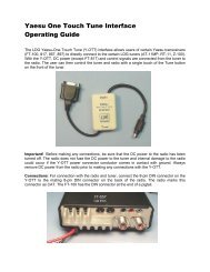
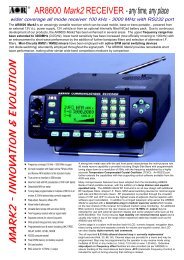
80M133’11’ 4”15M33’40M20M16’ 6”40M10M8’ 4”33’10M8’ 4”20M16’ 6”11’ 4”133’15M80MFigure 1Optimum Radial Lengths, Dimensions from Base to InsulatorAssembly and InstallationBefore you begin, read the instructions and study the illustrations. Compare the partsagainst the Parts List at the end of this manual. Decide where to mount your antenna(rooftop or ground) and what mode of transmission you will use (Phone, CW or Mid-Band). Take special notice of the dimensions in Figure 2. The SWR charts will help youdecide which dimensions to choose. See Figure 8.
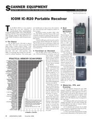
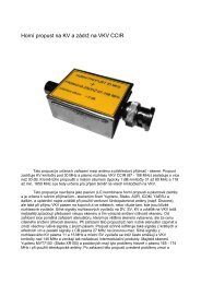
80 METERCAPACITACE SPOKES80 METER LOADING COIL40 METERCAPACITACE SPOKES16-20-2315-20 Meter Trap9-M417-25-28(Ground Mount)CW MB PH20.5” 22” 22.5”14.5” 13.5” 13”Item No. Description2 Base Assembly, 18<strong>AV</strong>QII4 Tube, M, 1 1/4” x 48” slotted5 Insulator, upper7 Tube, M2, 1 1/8” X 52”8 Tube, M3, 1” x 8”9 Tube, M4, 1” X 6 ½”10 Tube, M5, 7/16” x 56”11 Trap, 10 Meter14 Trap, 15 Meter15 Trap, 20 Meter16 Clamp, Tubing, No. 617 Clamp, Tubing, No. 1018 Clamp, Tubing, No. 1614-15 Meter Trap8-M317-25-288 3/4” 8 3/4” 8 3/4”11-10 Meter Trap12” 12” 12 1/4”18-25-287-M232”29”26”1-25-28 75CW MB PH(Ground Mount)Antenna Assembly Dimensions3Figure 2
TubingSelect the proper size tube clamps as shown in the chart. When installing the clamps,place the clamp near the tube end with the top of the clamp over the slot in the tube asshown in Figure 2. After adjustment of the tubing lengths, tighten the clamp with a 5/16inch nut driver, socket, or open end wrench until the tubing will not twist or telescope.DO NOT over-tighten!Figure 3 Tubing Clamps
CAUTION: All of the antenna dimensions must be set on the mode chosen - all CW, allmid-band or all phone. Mixing dimensions in an attempt to improve another mode oncertain bands will only degrade performance on all bands. Refer to Figure 2 inassembling the main portion of the antenna.M1 and M2 SectionPut a #16 tubing clamp (Item No. 18), un-tightened, over the M1 section (Item No. 4)(the base is attached to it already). Slip the 1 1/8" x 52" M2 section (Item No. 7) into thetop of the M1 and set the M2 at dimension 'A', as shown in Figure 1. Slide the clamp intoplace around the top of the M1 and tighten it just enough to keep the M2 from skipping.It will be fully tightened later.10-Meter TrapPut an un-tightened #10 Tubing clamp (Item No. 17) over the M2 section, then slip the 10meter trap (Item No. 11), bottom first, into the M2 section. (There is a plastic cover onthe top of all three parts.) Set the trap at dimension "C", as shown in Figure 1. Slip theclamp into place around the top of the M2 section and tighten it just enough to keep thetrap from slipping. It will be fully tightened later.15-Meter Trap and M3 Section AssemblyPlace two, un-tightened #10 tubing clamps (Item No. 17) over the 1" x 8" long M3section (Item No. 8). Slide the M3 section part way over the upper end of the 10-metertrap, then slide the lower end of the 15-meter trap (Item No. 14) into the M3 section. Setdimension "C", as shown in Figure 1, and locate the M3 so that it is equally spacedbetween the two traps. Tighten the clamps around the ends of the M3 just enough to keepparts from slipping. They will be fully tightened later.20-Meter Trap and M4 Section AssemblyAssemble these two parts like you did the M3 and the 15-meter trap. Use two more #10tubing clamps, the 1" x 6 1/2" long M4 section (Item No. 9) and the 20-meter trap (ItemNo.15).NOTE: There is a threaded metal insert in one end of the M5 section which will acceptthe #10-24 x 1" bolt (Item No. 20), which will hold the top hat in place. The end with theinsert must be at the top.M5 SectionPut a #6 tubing clamp (Item No. 16), un-tightened, over the swaged end of the 20- metertrap. Slip the 7/16" x 56" long M5 section (Item No. 10) into the swaged end of the trapand set dimension "E", as shown in Figure 1. Slide the clamp in place around the top ofthe swaged end of the trap tube and tighten it just enough to keep the M5 from slipping. Itwill be fully tightened later.Recheck all dimensions. Tighten all of the compression clamps securely in place.
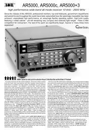
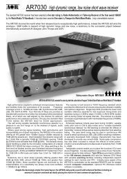
Top Loading Coil Assembly1. Remove the loading coil parts from the separate packaging. Check to see thateach is present using the packing list at the end of this instruction manual.2. Place a 4-40 screw in each of the 16 holes on the capacitance spoke rings and securethem using a 4-40-kep nut. Refer to figure 4. Snug each one using a 5/16” nut driver.Be careful not to lose the screws and nuts.3. Place the large end of the 1 1/8” X 17” aluminum tubing over the end of the loadingcoil assembly tube as shown in Figure 4.4. Secure the tubing in place with one of the supplied hose clamps. Be sure to place theconnection tab between the aluminum tubing and the clamp as shown in Figure 4.5. Place the remaining hose clamp onto the aluminum tube. This clamp is used to securethe MK-80 to an existing <strong>AV</strong>-14<strong>AV</strong>Q antenna. See Figure 4.6. Place four capacitance spokes into each of the spoke rings located on theloading coil assembly and secure them in place by tightening the 4-40 screws.80 METERCAPACITACE SPOKES80 METER LOADING COILLoading Coil AssemblyCAPACITANCE SPOKE RINGS40 METERCAPACITACE SPOKESTab1 1/8” x 17” TubingFigure 4
Installing the AntennaRefer to the mounting details in Figure 4 and 5 to install the completely assembledantenna.Figure 5 Antenna InstallationFirst mount the completed antenna on your mast (not supplied) as shown in Figure 5. Usethe two U-bolts, 5/16" nuts and 5/16" lock washers (Items Nos. 29, 31 and 30). Use three(3) 1/4"-20 x 3/4" bolts, nuts and lock washers (Item No’s 24, 27 & 26) to attach theinsulator to the upper end of the mounting bracket.If you are roof mounting your antenna, use four (4) sets of 1/4"-20 hardware for thepreceding step. Before tightening them, attach two adjacent radials to each set ofhardware as shown in Figures 3 and 5. If desired, you may use the four, 33 foot radialsystem shown.
NOTE: If your antenna is mounted more than three feet above ground, a resonant systemmust be added for proper operation.The radial system can serve to guy the system if insulators are used at the proper lengthsshown. This system must be grounded for lightning protection. Connect a ground wire toone U-bolt on the antenna base and run it to a buried, 8 foot (250 cm) ground rod by theshortest route. If you are ground mounting your antenna, install it as shown in Figure 4.You must install an 8 foot ground rod as shown.CAUTION: Keep the radials out of reach of children or pets. They are HOT with RFproportional to the power of the antenna.Figure 6
Figure 7Hooking Up the Antenna1. Connect your coax (RG-213/U) to the SO-239 connector at the bottom of the mountingbracket. (Coax not supplied.) Weather seal the coax connection with Coax- Seal© or anequivalent to prevent moisture from shorting out the connection. Final Adjustment(Optional Fine Tuning Of Your Installation)2. Because every antenna installation is influenced by the soil conditions and theproximity effect of nearby objects, the dimensions in the manual must be fine tuned toput the antenna VSWR exactly where you want it on each band.3. Beginning on 10 meters, make a VSWR curve checking the low end, center and highend of the band. This will indicate if the antenna favors the low end or the high end asinstalled.4. The antenna operates progressively from 10 thru 40 meters. Even though you may notbe using 10 meters at the present time, 10 meters must be adjusted, because any
adjustment made between the base and the first trap automatically changes all of thebands.a. If it favors the low end, shorten the 10- meter adjustment one inch or nomore than 1 1/2 inches. Run another VSWR measurement. Now you willhave an indication of how far that distance moved the antenna in yourlocation.Make what additional adjustments are indicated by the VSWR curve to put 10 metersexactly on the portion of the band you desire as your center operating frequency.b. If the antenna favors the high end, lengthen the dimensioncorrespondingly to move the antenna to a lower frequency as outlinedabove.5. Next, repeat this same procedure for 15 meters to put that band on frequency.6. The same procedure is then used to set up the 20-meter band, as well as the remainingbands available, depending upon the model involved.7. Most verticals are monopole antennas or half of a dipole. For this reason, the soilconditions, when the antenna is ground mounted, are important as it makes up the otherhalf of the antenna. When you roof mount the antenna, radials must be used as outlined inthe assembly instructions, to provide the other half of the antenna.Lightning ProtectionFor maximum lightning protection, we recommend the use of a <strong>Hy</strong>-<strong>Gain</strong> LA-1 LightningArrestor, available from your <strong>Hy</strong>-<strong>Gain</strong> dealer. Your antenna is now ready to use.Figure 8
Parts ListItemNo. Part No. Description Qty.2 871049 Base Assembly 14 190900 Tube, M1, 11/4 x 48", slotted 15 463056 Insulator, upper 16 523057 Screw, hex head, #10-24x1" 17 190303 Tube, M2, 11/8 x 52" 18 190603 Tube, M3, 1" x 8" 19 190605 Tube, M4, 1" x 6.5" 110 877157 Tube, M5, 7/16"x 56" 111 877132 Trap, 10 Meter 112 464723 Trap Cap, 7/8" x 15/8" 313 461466 Trap Spacer 414 877131 Trap, 15 Meter 115 877129 Trap, 20 Meter 116 358756 Clamp, Tubing No. 6 117 358757 Clamp, Tubing No. 10 518 358758 Clamp, Tubing No. 16 119 455624 Caplug, 1/8" dia 320 504069 Bolt, hex head, #10-24x1" 121 565697 Lockwasher, internal, #10 322 561165 Flatwasher, #10 423 555693 Nut, square, #10-24 124 505266 Bolt, hex head, 1/4 "-20 x 3/4" 426 562967 Lockwasher, internal, 1/4" 527 554099 Nut, Hex, 1/4-20 429 543792 U-Bolt, 5/16" x 15/8"x 21/4" 230 564792 Lockwasher, split 5/16 431 555747 Nut, hex, 5/16"-18 480 Meter Loading Coil Assembly Parts List1 190315 Tube 1 1/8" x 20" SW 1211-18avqii-1 Loading Coil Assembly 13810-0640-27 36" spokes 104 872016 Parts Pack 15656-0375S 6-32" x 3/8" 186705-06325-k 6-32" kep nuts 187 74531105 Hose Clamp 58 Manual(18-<strong>AV</strong>QII) 1
hy-gain® LIMITED WARR<strong>ANT</strong>Yhy-gain Warrants to the original owner of this product, if manufactured by hy-gain andpurchased from an authorized dealer or directly from hy-gain to be free from defects inmaterial and workmanship for a period of 12 months for rotator products and 24 monthsfor antenna products from date of purchase provided the following terms of this warrantyaresatisfied.1. The purchaser must retain the dated proof-of-purchase (bill of sale, canceled check,credit card or money order receipt, etc.) describing the product to establish thevalidity of the warranty claim and submit the original or machine reproduction ofsuch proof-of-purchase to hy-gain at the time of warranty service. hy-gain shall havethe discretion to deny warranty without dated proof-of-purchase. Any evidence ofalteration, erasure, or forgery shall be cause to void any and all warranty termsimmediately.2. hy-gain agrees to repair or replace at hy-gain’s option without charge to the originalowner any defective product under warranty, provided the product is returned postageprepaid to hy-gain.3. Under no circumstances is hy-gain liable for consequential damages to person orproperty by the use of any hy-gain products.4. Out-of-warranty Service: hy-gain will repair any out-of-warranty product providedthe unit is shipped prepaid. All repaired units will be shipped COD to the owner.Repair charges will be added to the COD fee unless other arrangements are made.5. This warranty is given in lieu of any other warranty expressed or implied.6. hy-gain reserves the right to make changes or improvements in design or manufacturewithout incurring any obligation to install such changes upon any of the productspreviously manufactured.7. All hy-gain products to be serviced in-warranty or out-of-warranty should beaddressed to hy-gain, 308 Industrial Park Road, Starkville,Mississippi 39759, USA and must be accompanied by a letter describing theproblem in detail along with a copy of your dated proof-of-purchase.8. This warranty gives you specific rights, and you may also have other rights whichvary from state to state.