Manual for Refrigeration Servicing Technicians - UNEP - Division of ...
Manual for Refrigeration Servicing Technicians - UNEP - Division of ...
Manual for Refrigeration Servicing Technicians - UNEP - Division of ...

Create successful ePaper yourself
Turn your PDF publications into a flip-book with our unique Google optimized e-Paper software.
<strong>Manual</strong> <strong>for</strong><br />
<strong>Refrigeration</strong><br />
<strong>Servicing</strong><br />
<strong>Technicians</strong> Introduction<br />
Why you need this manual 4<br />
When to use this manual 4<br />
How to use this manual 4<br />
Welcome to the <strong>Manual</strong> <strong>for</strong> <strong>Refrigeration</strong> <strong>Servicing</strong> <strong>Technicians</strong>.<br />
It is an e-book <strong>for</strong> people who are involved in training and<br />
organization <strong>of</strong> service and maintenance <strong>of</strong> refrigeration and airconditioning<br />
(RAC) systems. It is aimed at people who are:<br />
• Service and maintenance technicians<br />
• Private company service/maintenance managers<br />
• Private company managers involved in developing their<br />
service and maintenance policy<br />
• Private company technicians trainers<br />
• Educational establishment RAC trainers and course<br />
developers<br />
• National Ozone Units (NOUs) responsible <strong>for</strong> servicing<br />
and maintenance regulations and programmes related to<br />
the Montreal Protocol.
Introduction<br />
Why you need this <strong>Manual</strong><br />
Over recent years, attention on the issue <strong>of</strong> ozone depletion has<br />
remained focused on the obligatory phasing out <strong>of</strong> ozone depleting<br />
substances (ODS). At the same time, awareness <strong>of</strong> climate change<br />
has increased, along with the development <strong>of</strong> national and regional<br />
greenhouse gas (GHG) emissions reduction targets. In order to<br />
achieve reduction in emissions <strong>of</strong> both ODSs and GHGs, attention<br />
has to be paid to activities at a micro-level. This includes reducing<br />
leakage rates, improving energy-efficiency and preventing other<br />
environmental impacts, by directing the activities <strong>of</strong> individuals, and<br />
influencing the design and maintenance <strong>of</strong> equipment.<br />
The manual is written <strong>for</strong> those who have a relatively comprehensive<br />
level <strong>of</strong> knowledge and understanding <strong>of</strong> RAC systems and<br />
associated technology. The material within this manual may be<br />
used <strong>for</strong> the purpose <strong>of</strong> developing training resources or parts<br />
<strong>of</strong> training courses, as well as general guidance and in<strong>for</strong>mation<br />
<strong>for</strong> technicians on issues that are closely related to the use and<br />
application <strong>of</strong> alternative refrigerants. Most training courses are<br />
likely to cover a range <strong>of</strong> topics associated with RAC systems, and<br />
as such, the material within this manual may contribute towards<br />
those elements that address refrigerant use and handling.<br />
Read on to find out how 4<br />
2
Introduction<br />
When to use the manual<br />
The overall theme <strong>of</strong> this manual is to encourage technicians to<br />
work with systems in a more environmentally-friendly manner,<br />
and to get the equipment itself to have a lower impact. However,<br />
the primary motivation <strong>for</strong> technician operations carried out<br />
on a particular system is typically cost-orientated, rather than<br />
considering the environmental impact. It is <strong>of</strong>ten not recognised that<br />
actions resulting in a lesser environmental impact are consistent<br />
with a lower long-term cost impact. Conversely, the types <strong>of</strong> actions<br />
that are the “cheaper” options tend to lead to greater costs in the<br />
long term, as well as a worse environmental impact.<br />
For example:<br />
• A system that leaks may be topped-up or repaired. Topping-up<br />
may have a lower immediate cost, whereas repairing the leak<br />
takes more time and there<strong>for</strong>e costs more. However, in the longterm,<br />
the repaired system is less likely to leak thus the costs<br />
cease, whereas repeatedly topping-up a system over months<br />
and years results in a very high accumulated cost. Obviously,<br />
preventing leakage and thus fewer journeys to the equipment<br />
and better resulting efficiency is much more desirable from an<br />
environmental perspective.<br />
• A system that is designed to work efficiently and is well<br />
maintained may cost more to build, but the pay-back period is<br />
generally much shorter than the equipment’s lifetime. Similarly,<br />
the additional GHG emissions associated with constructing<br />
larger heat exchangers (<strong>for</strong> example) are minute compared to<br />
the reduction in GHG emissions from energy consumption that<br />
will be saved over the first year <strong>of</strong> operation.<br />
So, when installing a new system or working on an existing system,<br />
the actions taken should ideally lead to the system operating with<br />
minimal impact on the environment. To achieve this, several aspects<br />
should be borne in mind:<br />
• Reduce energy consumption by minimizing heat load and<br />
improving efficiency.<br />
• Minimize leakage and other emissions whenever possible.<br />
• Avoid the use <strong>of</strong> high global warming potential (GWP)<br />
refrigerants.<br />
Read on to decide how you might use this manual to achieve this 4<br />
3
Introduction<br />
How to use this manual<br />
The objectives on the page 6 When to use this manual may be<br />
achieved through a variety <strong>of</strong> means, including those detailed within<br />
this manual and from other sources. When a technician arrives at a<br />
system to carry out activities that involve refrigerant handling, and<br />
as they begin their work, they must <strong>for</strong>mulate a view as to how to<br />
deal with the system in hand.<br />
The considerations as to what to do with the system may include:<br />
Repair:<br />
Whether to repair and refill with the same refrigerant.<br />
Drop-in refrigerant change:<br />
Whether to repair and drop-in with a new refrigerant, and if so,<br />
which refrigerant to use.<br />
Retr<strong>of</strong>itting:<br />
Whether to repair and retr<strong>of</strong>it with a new refrigerant, and if so, which<br />
refrigerant to use.<br />
Redesign:<br />
Whether to repair, and add refrigerant, but also carry out other<br />
improvements to improve the reliability and efficiency.<br />
Replacement:<br />
Whether to replace the entire system with a new one, and if so,<br />
which system and which refrigerant.<br />
Read The Factors Affecting the Decision 4<br />
4
Introduction<br />
The Factors affecting the decision<br />
The decision as to which approach to take is rarely an obvious one, and<br />
requires consideration <strong>of</strong> many aspects.<br />
Type <strong>of</strong> refrigerant and its availability<br />
If a system uses a chlor<strong>of</strong>luorocarbon (CFC) then it is likely to<br />
be difficult to obtain, or even prohibited. The same will apply to<br />
hydrochlor<strong>of</strong>luorocarbons (HCFCs) in the future.<br />
Severity <strong>of</strong> leakage<br />
For systems that have a history <strong>of</strong> high leakage, perhaps due<br />
to poor manufacture or construction, or being positioned in a<br />
vulnerable location, consideration should be given to replacing<br />
them, or redesigning/reinstalling the susceptible parts.<br />
Charge <strong>of</strong> refrigerant<br />
If a system has a small charge <strong>of</strong> controlled or less available<br />
refrigerant, then it may not be so problematic to retain it, whereas if<br />
the charge is large then it would be sensible to replace it.<br />
Availability <strong>of</strong> alternative refrigerant<br />
The choice <strong>of</strong> alternative refrigerant should ideally be a substance<br />
with zero ozone depleting potential (ODP) i.e. not a CFC or HCFC or<br />
a blend that contains either. It should have as low a GWP as possible.<br />
Physical size <strong>of</strong> the system<br />
If a system is very large, replacing it with a new system may require<br />
considerable cost.<br />
Availability <strong>of</strong> similar (replacement) systems<br />
If the system is particularly complex and a replacement is being<br />
considered, it should only be done provided a replacement system<br />
is easily available.<br />
Availability <strong>of</strong> expertise associated with the type <strong>of</strong><br />
system<br />
Involved types <strong>of</strong> work or replacing parts or the entire system<br />
should only be done provided that sufficient expertise is available.<br />
Degree <strong>of</strong> integration into application<br />
Where a system is partially integrated into an application or a<br />
building, or is part <strong>of</strong> a much larger mechanical installation, it is<br />
likely to be much easier and more cost effective to carry out minimal<br />
work rather than trying to replace it with a new system.<br />
Condition/state <strong>of</strong> equipment<br />
For systems in a very poor condition, where perpetual maintenance and<br />
repairs are likely, then installation <strong>of</strong> a new system may be appropriate.<br />
5
Introduction<br />
Age <strong>of</strong> system<br />
If a system is very old and is using outdated technology and parts,<br />
it could be appropriate to replace it, whereas newer equipment may<br />
have modern design and already use suitable refrigerants.<br />
Current level <strong>of</strong> reliability<br />
If the reliability <strong>of</strong> the system and its components are poor, resulting<br />
in repeated service visits and losses <strong>of</strong> parts and refrigerant, then a<br />
replacement system may be the preferred option.<br />
System efficiency and potential <strong>for</strong> efficiency<br />
improvement<br />
If a system has a poor level <strong>of</strong> efficiency, it is necessary to consider<br />
whether there are viable operations that could be carried out to help<br />
improve the efficiency, but it is such that this is not possible, then<br />
adoption <strong>of</strong> a new system should be considered.<br />
The choice is <strong>of</strong>ten complex<br />
and a function <strong>of</strong> many different<br />
factors. Typically, the age <strong>of</strong><br />
the equipment is a leading factor<br />
in terms <strong>of</strong> which conclusions<br />
are drawn in terms <strong>of</strong> how the<br />
equipment should be handled,<br />
<strong>for</strong> the reasons implied above.<br />
6
Introduction<br />
How to assess conditions<br />
Here is an overview <strong>of</strong> conditions <strong>for</strong> the refill, drop-in, retro-fit and<br />
new system options, which includes considerations that should be<br />
given to how a system is handled.<br />
Considering these factors, read the conditions below and then select the<br />
option you might choose<br />
The conditions 4<br />
CHAPITRE 1<br />
PAGE 06<br />
HOW TO ASSESS CONDITIONS<br />
FULL INTEGRATED<br />
INTO APPLICATION ?<br />
LIMITED<br />
AVAILABILITY OF<br />
NEW SYSTEMS ?<br />
HCFC , HFC ,<br />
NATURAL<br />
REFRIGERANT ?<br />
LOW LEAKAGE ?<br />
NOT INTEGRATED<br />
INTO APPLICATION ?<br />
EXTENSIVE<br />
AVAILABILITY OF<br />
NEW SYSTEMS ?<br />
HIGH LEAKAGE ?<br />
CFC REFRIGERANT ?<br />
SYSTEM IN GOOD<br />
CONDITION ?<br />
NO EXPERTISE FOR<br />
NEW SYSTEMS ?<br />
SYSTEM IN POOR<br />
CONDITION ?<br />
EXISTING<br />
SYSTEM<br />
EXTENSIVE<br />
EXPERTISE FOR NEW<br />
SYSTEMS ?<br />
NEW<br />
SYSTEM<br />
GOOD RELIABILITY?<br />
GOOD EFFICIENCY ?<br />
POOR RELIABILITY?<br />
POOR EFFICIENCY ?<br />
7<br />
SMALL CHARGE ?<br />
NOT MANY YEARS<br />
OLD ?<br />
GOOD POTENTIAL<br />
FOR EFFICIENCY<br />
IMPROVEMENT ?<br />
LARGE CHARGE ?<br />
MANY YEARS OLD ?<br />
POOR POTENTIAL<br />
FOR EFFICIENCY<br />
IMPROVEMENT ?
Introduction<br />
Refrigerant type and<br />
availability<br />
Condition Observation<br />
HFC, CO2, HC,<br />
NH3<br />
CFC, HCFC HCFC CFC<br />
Severity <strong>of</strong> leakage low low medium high<br />
Charge <strong>of</strong> refrigerant high medium medium low<br />
Alternative refrigerant<br />
availability<br />
poor good good good<br />
Physical size <strong>of</strong> system large large medium small<br />
Availability <strong>of</strong> similar systems none none none many<br />
Availability <strong>of</strong> system expertise none some some much<br />
Degree <strong>of</strong> integration high high medium low<br />
Condition/state <strong>of</strong> equipment good good fair poor<br />
Age <strong>of</strong> system new medium medium old<br />
Current level <strong>of</strong> reliability good good fair poor<br />
System efficiency good good medium poor<br />
Efficiency improvement<br />
potential<br />
good good medium poor<br />
Recommended action: Repair and refill Drop-in Retr<strong>of</strong>it New system<br />
8
Introduction<br />
Characteristics <strong>of</strong> Selected Types <strong>of</strong> Equipment<br />
Different types <strong>of</strong> equipment have certain characteristics associated with them, that<br />
may affect some aspects <strong>of</strong> the decision-making and some <strong>of</strong> these are listed in the<br />
Characteristics <strong>of</strong> Selected Types <strong>of</strong> Equipment sheet<br />
Application example System Type Relative Charge<br />
Integrated into<br />
Application<br />
Domestic refrigeration integral small low<br />
Stand alone retail food display and<br />
vending<br />
integral small low<br />
Condensing unit refrigeration remote medium medium<br />
Large supermarket systems distributed large medium<br />
Cold storage remote large medium<br />
Industrial process refrigeration all medium, large high<br />
Refrigerated transport remote medium high<br />
Split and ducted air conditioners remote medium medium<br />
Portable & window air conditioner units integral small low<br />
Heat pumps all medium, large medium<br />
Chillers integral medium, large medium<br />
Mobile air conditioning (MAC) Integral small high<br />
9
Introduction<br />
Further in<strong>for</strong>mation<br />
The in<strong>for</strong>mation within this manual was drawn from a variety<br />
<strong>of</strong> different sources. However, rather than providing a detailed<br />
reference list, each chapter is accompanied by a short list <strong>of</strong><br />
publications <strong>for</strong> further reading. These publications cover a large<br />
amount <strong>of</strong> in<strong>for</strong>mation on the topics addressed within this manual.<br />
There are also a large number <strong>of</strong> textbooks on the subject <strong>of</strong><br />
refrigeration engineering, and a selection <strong>of</strong> those is listed below.<br />
Amongst these, are addressed many <strong>of</strong> the topics covered within<br />
this manual, particularly related to servicing and maintenance<br />
practices:<br />
Air Conditioning and <strong>Refrigeration</strong>, by R Miller and M R Miller, 2006<br />
Modern <strong>Refrigeration</strong> and Air Conditioning, by A D Althouse, C H Turnquist,<br />
and A F Bracciano, 2004<br />
Principles <strong>of</strong> <strong>Refrigeration</strong>, by R J Dossat and T J Horan, 2001<br />
<strong>Refrigeration</strong> and Air Conditioning Technology, by B Whitman, B Johnson, J<br />
Tomczyk, E Silberstein, 2008<br />
<strong>Refrigeration</strong> Equipment: A <strong>Servicing</strong> and Installation Handbook, by A C<br />
Bryant, 1997<br />
More generally, there exist a large number <strong>of</strong> organizations who<br />
have Internet sites from where extensive in<strong>for</strong>mation can be found<br />
related to the subjects <strong>of</strong> refrigeration and refrigerants.<br />
A selection are:<br />
4 www.ammonia21.com - related to the ammonia refrigeration industry<br />
4 www.ashrae.org<br />
American Society <strong>of</strong> Heating, Air-conditioning and <strong>Refrigeration</strong> Engineers<br />
4 www.eurammon.com<br />
Eurammon - the European trade association <strong>for</strong> the use <strong>of</strong> natural<br />
refrigerants<br />
4 www.hydrocarbons21.com<br />
Hydrocarbons21 - related to the hydrocarbon refrigeration industry<br />
4 www.iiar.org - International Institute <strong>of</strong> Ammonia <strong>Refrigeration</strong><br />
4 www.iifiir.org - International Institute <strong>of</strong> <strong>Refrigeration</strong><br />
4 www.r744.com<br />
Everything R744 - related to the carbon dioxide refrigeration industry<br />
4 www.refrigerantsnaturally.com<br />
Refrigerants, Naturally! - an organization <strong>of</strong> end-users involved in the<br />
adoption <strong>of</strong> natural refrigerants<br />
4 www.unep.org/ozone/<br />
<strong>UNEP</strong> Ozone Secretariat – website <strong>of</strong> the Secretariat <strong>of</strong> the Vienna<br />
Convention and the Montreal Protocol: Ozone Secretariat<br />
4 www.uneptie.org/ozonaction<br />
<strong>UNEP</strong> DTIE OzonAction – website <strong>of</strong> the OzonActon Branch as an<br />
implementing agency and clearinghouse function<br />
10
Introduction<br />
Another <strong>for</strong>m <strong>of</strong> reference in<strong>for</strong>mation pertinent to the application <strong>of</strong><br />
refrigeration systems and refrigerants is standards, which are usually<br />
a description <strong>of</strong> procedures or technical requirements that should<br />
enable individuals or companies to achieve equivalence in the<br />
activity under consideration.<br />
For example, following refrigeration safety standards should ensure<br />
that two separate refrigerating systems achieve an equivalent<br />
level <strong>of</strong> safety, and following per<strong>for</strong>mance standards should<br />
ensure that two separate organizations would measure the same<br />
per<strong>for</strong>mance <strong>of</strong> the same system. Furthermore, they are intended<br />
to help practitioners avoid problems, errors and pitfalls that they<br />
may otherwise encounter if they did not follow the guidance <strong>of</strong> the<br />
standards.<br />
Standards are published by a variety <strong>of</strong> different organizations.<br />
At a country level, national standardization bodies publish<br />
national standards (although in many cases these may be<br />
based on other countries’ standards or international standards).<br />
European standardization bodies publish a European standard,<br />
which are typically adopted by national standardization bodies<br />
within European countries. Internationally, there are two main<br />
organizations which publish international standards.<br />
The numbers <strong>of</strong> national, European and International standards that<br />
apply to the RAC sector are vast, and the reader should seek out<br />
the most relevant ones when and where necessary.<br />
Here, a small selection <strong>of</strong> such standards is listed to provide an indication <strong>of</strong><br />
what may be relevant to this subject area:<br />
EN 378: 2008 – <strong>Refrigeration</strong> systems and heat pumps, safety and<br />
environmental requirements;<br />
This is comprised <strong>of</strong> four parts<br />
• Part 1: basic requirements, classification and selection criteria<br />
• Part 2: design, construction, testing, marking and documentation<br />
• Part 3: Installation site and personal protection<br />
• Part 4: Operation, maintenance, repair and recovery<br />
EN 13313: 2008 – <strong>Refrigeration</strong> systems and heat pumps, Competence <strong>of</strong><br />
personnel; this addresses the level <strong>of</strong> competence that is necessary<br />
<strong>for</strong> engineers and technicians to carry out different activities<br />
ISO 817: 2005 – Refrigerants – designation and system classification; this<br />
covers the R-numbering system <strong>for</strong> refrigerants and the means <strong>for</strong><br />
their safety classification<br />
ISO 5149: 1993 – Mechanical refrigerating systems used <strong>for</strong> cooling and<br />
heating – Safety requirements; this current version is rather dates, but<br />
it is currently under revision and is similar to EN 378<br />
ISO 916: 1968 – Testing <strong>of</strong> refrigerating systems; this covers the<br />
determination <strong>of</strong> the technical per<strong>for</strong>mance <strong>of</strong> a refrigerating<br />
system (but not the functional duty <strong>of</strong> a complete installation or the<br />
per<strong>for</strong>mance <strong>of</strong> its individual components)<br />
11
Introduction<br />
Other International and European standards, as well as various national<br />
standards also address the following subject matter:<br />
Properties <strong>of</strong> refrigerant and lubricants<br />
Per<strong>for</strong>mance testing <strong>of</strong> systems including energy consumption<br />
(refrigeration, air conditioners, heat pumps, etc) and components<br />
Per<strong>for</strong>mance <strong>of</strong> refrigeration-related equipment (such as recovery,<br />
recycling, vacuum equipment)<br />
Per<strong>for</strong>mance testing <strong>of</strong> refrigerated display equipment, and refrigerated<br />
storage equipment<br />
Design, construction and selection <strong>of</strong> system safety devices (such as<br />
pressure relief and pressure limiting devices)<br />
Safety design, construction and selection <strong>of</strong> system components (such as<br />
vessels and pipes)<br />
Safety <strong>of</strong> appliances (such as domestic refrigerators and freezers,<br />
commercial refrigerating equipment, air conditioners, dehumidifiers and<br />
heat pumps)<br />
Testing <strong>of</strong> airborne noise levels <strong>of</strong> refrigeration, air conditioners, heat pump<br />
equipment<br />
Electrical safety <strong>of</strong> refrigeration, air conditioners, heat pump equipment<br />
Such standards can be obtained from the relevant standardization<br />
organizations:<br />
4 www.iso.org - International Standardisation Organisation<br />
4 www.cen.eu - Comité Européen de Normalisation<br />
4 www.iec.ch - International Electro-technical Commission<br />
4 www.cenelec.eu - Comité Européen de Normalisation Electrotechnique<br />
12
Introduction<br />
Choose your chapter<br />
Throughout the lifetime <strong>of</strong> the equipment, a variety <strong>of</strong> activities<br />
are carried out by different personnel and accordingly, a range<br />
<strong>of</strong> knowledge is needed. The content <strong>of</strong> this manual is intended<br />
to provide a large portion <strong>of</strong> that, particularly <strong>for</strong> those who are<br />
involved in refrigerant handling. We have summarised the major<br />
activities involved during the start-<strong>of</strong>-life, operation and end-<strong>of</strong>life<br />
stages <strong>of</strong> RAC equipment. For each <strong>of</strong> these activities, the<br />
most important chapters <strong>of</strong> this manual have been identified.<br />
Thus, any training course or technical guidance specifically <strong>for</strong> any<br />
one <strong>of</strong> these activities can be focused on the material within the<br />
corresponding chapters.<br />
The primary objective <strong>of</strong> this<br />
manual is to provide the reader<br />
with the appropriate background<br />
in<strong>for</strong>mation to enable him/her to gain<br />
an adequate level <strong>of</strong> understanding<br />
related to the key topics addressed.<br />
The diagram on the next page<br />
summarizes the contents <strong>of</strong> this<br />
manual.<br />
13
Introduction<br />
END OF LIFE OPERATION<br />
START OF LIFE<br />
Click on any<br />
<strong>of</strong> the chapter<br />
bars to visit<br />
that section<br />
DESIGN<br />
ASSEMBLY<br />
INSTALLATION<br />
COMMISSIONING<br />
MAINTE<br />
-NANCE<br />
SERVICE<br />
DECOMMISSIONING<br />
DISPOSAL<br />
CHAPTER 1<br />
ENVIRONMENTAL<br />
IMPACT<br />
sets the overall<br />
context <strong>for</strong> the<br />
manual, being<br />
the environmental<br />
impact <strong>of</strong> refrigerants<br />
and thus<br />
the introduction<br />
<strong>of</strong> alternative<br />
refrigerants<br />
CHAPTER 2<br />
REFRIGERANTS<br />
provides a broad<br />
overview <strong>of</strong> most<br />
<strong>of</strong> the issues<br />
associated with<br />
refrigerants.<br />
CHAPTER 3<br />
REFRIGERANTS<br />
MANAGEMENT<br />
covers a variety <strong>of</strong><br />
important aspects<br />
related to the<br />
handling and<br />
management <strong>of</strong><br />
refrigerants, with<br />
the primary focus<br />
on maintaining good<br />
quality refrigerant<br />
and avoiding<br />
emissions and<br />
wastage.<br />
CHAPTER 4<br />
SERVICING<br />
PRACTICES<br />
covers methods<br />
and techniques<br />
that are used when<br />
working on<br />
systems, primarily<br />
during servicing<br />
exercises.<br />
CHAPTER 5<br />
RETROFITTING<br />
addresses the<br />
approach and<br />
working procedures<br />
<strong>for</strong> changing<br />
refrigerants within<br />
an existing system.<br />
14<br />
CHAPTER 6<br />
SAFE REFRIGERANT<br />
HANDLING<br />
covers the relevant<br />
safety with refrigerants.<br />
There is a general<br />
description <strong>of</strong> the<br />
safety implications<br />
<strong>of</strong> refrigerants,<br />
including toxicity,<br />
oxygen displacement,<br />
flammability, degradation<br />
products, and high<br />
pressure to highlight<br />
the major hazards.
1<br />
Environmental<br />
impact <strong>of</strong><br />
refrigeration and<br />
air conditioning<br />
(rac) systems<br />
Content<br />
The ozone layer 4<br />
The ozone layer and the Montreal Protocol 4<br />
Effects <strong>of</strong> ozone layer depletion on the environment 4<br />
Alternative refrigerants and regulations 4<br />
The way <strong>for</strong>ward 4<br />
Further reading 4
1<br />
Summary 1.1. Introduction<br />
Initially the ozone layer is described and the impact<br />
that certain refrigerants have on it. The concept <strong>of</strong><br />
global warming is also described and the impact <strong>of</strong><br />
some refrigerants, and the energy-related impact<br />
associated with the operation <strong>of</strong> refrigeration<br />
systems are discussed. The primary motivation <strong>for</strong><br />
the introduction <strong>of</strong> alternative refrigerants, namely the<br />
Montreal Protocol and latterly the Kyoto Protocol are<br />
emphasized.<br />
The reader should be able to:<br />
• Identify the main environmental problems related<br />
to RAC installations<br />
• Identify the role <strong>of</strong> chlor<strong>of</strong>luorocarbon (CFC) and<br />
hydrochlor<strong>of</strong>luorocarbon (HCFC) refrigerants in<br />
ozone layer depletion<br />
• Identify how RAC contributes to global warming<br />
• Identify the measures <strong>of</strong> the Montreal Protocol<br />
and the schedule <strong>for</strong> refrigerants phase-out.<br />
Environmental Impact<br />
<strong>Refrigeration</strong>, air conditioning and heat pump applications represent<br />
the major consumer <strong>of</strong> halogenated chemical substances used as<br />
refrigerants; it is also one <strong>of</strong> the most important energy sector users<br />
in our society today. It is estimated that, on average, <strong>for</strong> developed<br />
countries, the RAC sectors are responsible <strong>for</strong> 10-20% <strong>of</strong> electricity<br />
consumption.<br />
The economic impact <strong>of</strong> refrigeration applications is significant;<br />
estimates indicate 300 million tonnes <strong>of</strong> continually refrigerating<br />
goods, with huge annual electricity consumption, and about US$<br />
100 billion in equipment investments, where the estimated value <strong>of</strong><br />
the products treated by refrigeration are about four times this sum.<br />
This is one <strong>of</strong> the reasons why economic impacts <strong>of</strong> the elimination<br />
<strong>of</strong> refrigerant chemical substances such as CFCs and in the near<br />
future HCFCs have been hard to calculate.<br />
Although HCFCs had been used since the 1930s, because <strong>of</strong><br />
their relatively low ozone depleting potential (ODP), they were not<br />
at first included in the controls <strong>for</strong> ODS. As such, they were used<br />
within mixture <strong>of</strong> other chemical compounds to enable the easy<br />
replacement <strong>of</strong> CFCs. It was, however, acknowledged at the time<br />
that these chemicals were transitional since their production and<br />
consumption was also to be phased out under the Montreal Protocol.<br />
About The Ozone Layer 4<br />
About the Montreal Protocol 4
1<br />
Environmental Impact<br />
The ozone layer<br />
As the sun’s radiation approaches the planet’s surface it can be<br />
scattered, reflected, or absorbed, intercepted and re-emitted. This<br />
is where the ozone layer comes into its own by scattering and<br />
reflecting harmful high energy ultraviolet radiation. Variations in<br />
temperature and pressure divide the Earth’s atmosphere into layers<br />
and the mixing <strong>of</strong> gases between the layers happens very slowly.<br />
That is why this 90% <strong>of</strong> the ozone stays in the upper atmosphere.<br />
This stratospheric ozone contains 90% <strong>of</strong> all ozone gas on the<br />
Earth but it is spread thinly and unevenly.<br />
Life on earth has been safeguarded because <strong>of</strong> a protective layer<br />
in the atmosphere. This layer, composed <strong>of</strong> ozone, acts as a shield<br />
to protect the earth against the harmful ultraviolet radiation from<br />
the sun. Ozone is a <strong>for</strong>m <strong>of</strong> oxygen with three atoms (O3) instead <strong>of</strong><br />
two (O2). Through natural atmospheric processes, ozone molecules<br />
are created and destroyed continuously. Ultraviolet radiation<br />
from the sun breaks up oxygen molecules into atoms which then<br />
combine with other oxygen molecules to <strong>for</strong>m ozone. Ozone is not<br />
a stable gas and is particularly vulnerable to destruction by natural<br />
compounds containing hydrogen, nitrogen and chlorine.<br />
Near the earth’s surface (the troposphere) ozone is an increasingly<br />
troublesome pollutant, a constituent <strong>of</strong> photochemical smog and<br />
acid rain. But safely up in the stratosphere, 11 to 48 km above the<br />
earth’s surface, the blue, pungent-smelling gas is as important<br />
to life as oxygen itself. Ozone <strong>for</strong>ms a fragile shield, curiously<br />
insubstantial but remarkably effective.<br />
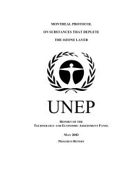
The distribution <strong>of</strong> ozone in the atmosphere is illustrated in Figure 1.1.<br />
ALTITUDE (KILOMETERS)<br />
35<br />
30<br />
25<br />
20<br />
15<br />
10<br />
5<br />
0<br />
OZONE LAYER<br />
OZONE<br />
INCREASES<br />
FROM POLLUTION<br />
OZONE CONCENTRATION<br />
Distribution <strong>of</strong> ozone in atmosphere.<br />
STRATOSPHERIC<br />
OZONE<br />
TROPOSPHERIC<br />
OZONE<br />
17<br />
20<br />
15<br />
10<br />
05<br />
ALTITUDE (MILES)
1<br />
Environmental Impact<br />
1. The exosphere<br />
(2400km))<br />
The sunlight still contains very high-energy photons, which can heat gas<br />
particles in the exosphere up to 2,500 degrees C during the day.<br />
2. The ionosphere Most high energy photons are absorbed here leading to a few air<br />
molecules becoming electrically charged.<br />
3. The ozone layer This thin layer at the top <strong>of</strong> the stratosphere absorbs most <strong>of</strong> the ultraviolet<br />
(UV) light. Too much UV light can cause damage to living things<br />
so the ozone layer is very important in protecting life on Earth.<br />
4.The stratosphere<br />
(50km)<br />
5. The troposphere (8-15<br />
km).<br />
6. Absorption <strong>of</strong><br />
radiation emitted by the<br />
Earth<br />
Ozone depletion relies on the clouds in the stratosphere: Polar<br />
stratospheric clouds (PSCs), also known as nacreous clouds, are<br />
CLOUDS in the winter polar STRATOSPHERE at altitudes <strong>of</strong> 15,000–25,000<br />
metres (50,000–80,000 ft). They are implicated in the <strong>for</strong>mation <strong>of</strong> OZONE<br />
HOLES; [1] their effects on ozone depletion arise because they support<br />
chemical reactions.<br />
The troposphere contains most <strong>of</strong> the air molecules, nearly all the water<br />
vapour so all <strong>of</strong> the clouds are in this layer. All these particles mean that<br />
a lot <strong>of</strong> sunlight is scattered. Shorter wavelengths (violet and blue) are<br />
scattered more than longer wavelengths, making the sky appear blue.<br />
The Earth emits a lot <strong>of</strong> long wavelength radiation from its surface and<br />
much <strong>of</strong> this is absorbed and scattered in the troposphere. Greenhouse<br />
gases such as carbon dioxide and water vapour are responsible <strong>for</strong><br />
most <strong>of</strong> this absorption, making the temperature around the Earth<br />
higher.<br />
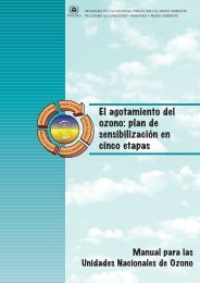
This ozone filter efficiently screens out almost<br />
all the harmful ultraviolet rays <strong>of</strong> the sun; the<br />
ozone layer absorbs most <strong>of</strong> the dangerous<br />
UV-B radiation (radiation between UV-A which<br />
is allowed through and UV-C which is mainly<br />
captured by oxygen, as indicated in Figure<br />
1.2). Any damage that is done to the ozone<br />
layer will lead to increased UV-B radiation.<br />
Increases <strong>of</strong> UV-B radiation have been clearly<br />
observed in areas experiencing periods <strong>of</strong><br />
intense ozone depletion.<br />
Any increased UV-B that reaches the earth’s<br />
surface has a potential to cause considerable<br />
harm to the environment and to life on earth.<br />
A small decrease in the ozone layer could<br />
significantly increase the incidence <strong>of</strong> skin<br />
cancer, and could lead to an acceleration<br />
<strong>of</strong> the rarer but more virulent <strong>for</strong>m <strong>of</strong><br />
cancer known as coetaneous malignant<br />
melanoma. Increased UV-B could lead to<br />
increased incidents <strong>of</strong> eye damage, including<br />
cataracts, de<strong>for</strong>mation <strong>of</strong> the eye lenses, and<br />
presbyopia. Eye cataracts, the leading cause<br />
<strong>of</strong> blindness in the world, are expected to<br />
increase considerably.<br />
18
1<br />
Environmental Impact<br />
RADIATION FROM THE SUN<br />
UV-B<br />
Figure 1.2. Radiation from the sun<br />
DONE<br />
UV-A<br />
OZONE LAYER<br />
EARTH<br />
UV rays are dangerous to human beings,<br />
animals and plants because they burn. They<br />
can penetrate our skin and eyes and weaken<br />
our bodies’ immune system. That is why we<br />
should avoid long periods in the sun. To get<br />
the minimum daily dose <strong>of</strong> vitamin D only 15<br />
minutes in the sun per day is enough. If we<br />
stay more than that, we might get sunburnt if<br />
no protection is used. Repeated sunburns and<br />
frequent tanning can cause premature ageing<br />
<strong>of</strong> the skin and, at worst, skin cancer such as<br />
melanoma (because <strong>of</strong> UV-A and UV-B). For<br />
the eyes the UV-B rays can cause a cataract<br />
(clouding <strong>of</strong> the eye lens). Most <strong>of</strong> the serious<br />
health problems appear only many years later.<br />
CATEGORY WAVELENGTHS<br />
(nanometres)<br />
REACTIONS IN &<br />
WITH<br />
STRATOSPHERE<br />
UV-A: 315/320 - 400 nm Not significantly<br />
absorbed by the<br />
stratospheric ozone<br />
layer.<br />
UV-B: 280 – 315/320 nm Absorbed by ozone<br />
in the stratosphere.<br />
Ozone absorbs UV<br />
radiation without<br />
being reduced; the<br />
overall result being<br />
to convert UV<br />
radiation to heat.<br />
UV-C: 200 - 280 nm Highly absorbed by<br />
oxygen molecules:<br />
involved with<br />
<strong>for</strong>mation <strong>of</strong> ozone.<br />
EFFECT UPON<br />
HUMANS, PLANTS ETC.<br />
10-15% <strong>of</strong> ‘burning’:<br />
possible connection with<br />
the <strong>for</strong>mation <strong>of</strong> skin<br />
cancers. Responsible <strong>for</strong><br />
'tanning' & skin ageing.<br />
85 – 90 % ‘burning’;<br />
involved with both<br />
malignant & benign<br />
cancerous growths. Also<br />
linked to eye cataracts.<br />
Effects on growth <strong>of</strong> plants<br />
and marine life. Strong<br />
radiation kills also plankton<br />
in the water which is the<br />
main food supply <strong>for</strong><br />
fishes.<br />
Not thought to be<br />
significant, mainly because<br />
<strong>of</strong> its efficient absorption<br />
at high-altitudes.<br />
19
1<br />
Environmental Impact<br />
Exposure to increased UV-B radiation could also suppress the body’s<br />
immune system.<br />
Immunosuppression by UV-B occurs irrespective <strong>of</strong> human skin<br />
pigmentation. Such effects could exacerbate the poor health<br />
situations <strong>of</strong> many developing countries.<br />
Increased UV-B radiation could also cause decreased crop yields<br />
and damage to <strong>for</strong>ests. It could affect ocean life causing damage to<br />
aquatic organisms, parts <strong>of</strong> the marine food web, which may lead<br />
to a decrease in fish higher up the food chain. Materials used in<br />
buildings, paints, packaging and countless other substances could<br />
be rapidly degraded by increased UV-B.<br />
Depletion <strong>of</strong> stratospheric ozone could aggravate the<br />
photochemical pollution in the troposphere resulting in an increase<br />
<strong>of</strong> ozone at the surface <strong>of</strong> the earth where it is not wanted. Earth<br />
and inhabitants, there<strong>for</strong>e, have an enormous stake in preserving<br />
the fragile ozone layer shield.<br />
Global consensus supports the theory that chlorine and bromine<br />
containing man-made chemicals emitted into the atmosphere are<br />
responsible <strong>for</strong> the depletion <strong>of</strong> ozone in the stratosphere. The<br />
larger part <strong>of</strong> these compounds, called ODS, consists <strong>of</strong> CFCs,<br />
HCFCs and halons (used as fire extinguishing agents), which are<br />
most effective in ozone depletion. CFCs have been used <strong>for</strong> years<br />
as refrigerants, solvents or blowing agents. ODS are classified<br />
considering how harmful they are <strong>for</strong> the ozone layer using a<br />
parameter called ozone depleting potential (ODP).<br />
ODP is a relative index indicating the extent to which a chemical<br />
product may cause ozone depletion. The reference level <strong>of</strong> 1 is the<br />
potential <strong>of</strong> R11 and R12 to cause ozone depletion. If a product<br />
has an ODP <strong>of</strong> 0.5, a given weight <strong>of</strong> the product in the atmosphere<br />
would, in time, destroy half the amount <strong>of</strong> ozone that the same<br />
weight <strong>of</strong> R11 would destroy. ODP is calculated from mathematical<br />
models which take into account factors such as the stability <strong>of</strong> the<br />
product, the rate <strong>of</strong> diffusion, the quantity <strong>of</strong> depleting atoms per<br />
molecule and the effect <strong>of</strong> ultraviolet light and other radiation on the<br />
molecules.<br />
20
1<br />
Environmental Impact<br />
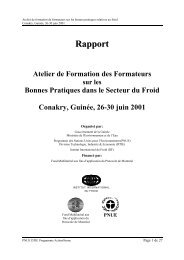
The ozone layer and the Montreal Protocol<br />
CFCs (ANNEX A/I) PRODUCTION/CONSUMPTION REDUCTION SCHEDULE<br />
<strong>UNEP</strong> has been concerned about the protection <strong>of</strong> the<br />
ozone layer since its inception in 1972. In March 1985,<br />
the Convention <strong>for</strong> the Protection <strong>of</strong> the Ozone Layer<br />
120 %<br />
NON - A5<br />
ARTICLE 5<br />
CFC-NON-A5<br />
was signed in Vienna. The Convention provided <strong>for</strong> future<br />
protocols and specified procedures <strong>for</strong> amendment<br />
and dispute settlement. In September 1987, agreement<br />
100 %<br />
BASELINE<br />
1989<br />
BASELINE<br />
95-97<br />
CFC-A5<br />
was reached on specific measures to be taken and the<br />
Montreal Protocol on Substances that Deplete the Ozone<br />
80 %<br />
Layer was signed. Under the Protocol, the first concrete<br />
step to protect the ozone layer was taken, a 50%<br />
60 %<br />
reduction in the production and consumption <strong>of</strong> specified<br />
CFCs by the year 1999.<br />
Even as the nations adopted the Protocol in 1987, new<br />
40 %<br />
20 %<br />
scientific findings indicated that the Protocol’s control<br />
0 %<br />
measures were inadequate to restore the ozone layer. In<br />
JAN- JAN- JAN- JAN- JAN- JAN- JAN- JAN- JAN- JAN- JAN- JAN- JAN- JAN- JANaddition,<br />
developing countries expressed concern over<br />
the vague language both regarding technology transfer to<br />
1986 1988 1990 1992 1994 1996 1998 2000 2002 2004 2006 2008 2010 2012 2014<br />
developing countries and regarding financial assistance.<br />
MONTH/YEAR<br />
As a result <strong>of</strong> the Second Meeting <strong>of</strong> the Parties in<br />
London (1990), the Montreal schedules were adjusted so that the<br />
five CFCs (R11, R12, R113, R114 and R115) and the three halons<br />
Figure 1.3 Article 5 and Non-Article 5 countries phase-out schedules <strong>of</strong><br />
Annex A Group I CFCs<br />
would be phased out by the year 2000. Methyl chloro<strong>for</strong>m was to The <strong>UNEP</strong> Assessment Panels did a substantial amount <strong>of</strong> work in 1991. These<br />
be controlled and to be phased out in 2005. Figure 1.3 shows the Panels consider the science, the effects and the technology that is in place to<br />
CFC phase-out schedules <strong>for</strong> Article 5 and Non-Article 5 countries. replace and phase out the controlled chemicals.<br />
21
1<br />
Environmental Impact<br />
On the basis <strong>of</strong> these reports the parties to the Montreal Protocol<br />
discussed again a tightening <strong>of</strong> the control schedules.<br />
Achieving the goals <strong>of</strong> the Montreal Protocol depends on<br />
widespread cooperation among all the nations <strong>of</strong> the world. It is not<br />
enough that the developed nations, which accounted in 1986 <strong>for</strong><br />
85% <strong>of</strong> the consumption <strong>of</strong> ODS, participate in the Protocol. The<br />
participation <strong>of</strong> developing countries, which consumed only 15%<br />
in 1986, is also vitally important. HCFC consumption in developing<br />
countries has been growing at a much higher rate than in the<br />
developed world.<br />
As long ago as 1987, developing countries were given incentives<br />
to con<strong>for</strong>m with the Protocol in the <strong>for</strong>m <strong>of</strong> a grace period <strong>of</strong> 10<br />
years <strong>for</strong> implementation and technical assistance (Articles 5 and<br />
10 in the Protocol). However, by 1989 many <strong>of</strong> the larger developing<br />
nations indicated that the provisions were inadequate. They argued<br />
that it was not they that were responsible <strong>for</strong> depleting the ozone<br />
layer. And as they are just beginning to develop economically and<br />
to use the low cost CFC technology acquired from the developed<br />
countries, they require help with the costs. If they are to bind<br />
themselves to strict schedules <strong>for</strong> adopting new technologies, they<br />
need to be given the new technologies and the finance necessary to<br />
adopt them. Negotiations on this issue resulted in the establishment<br />
<strong>of</strong> a new financial mechanism in London, 1990, through a new<br />
Article 10 in the Montreal Protocol.<br />
The mechanism includes a Multilateral Fund and other multilateral,<br />
regional and bilateral co-operation. The Fund has now operated<br />
since 1991; under the Fund, <strong>UNEP</strong> OzonAction is responsible <strong>for</strong><br />
in<strong>for</strong>mation dissemination, training and networking. This manual<br />
is part <strong>of</strong> <strong>UNEP</strong>’s work programme related to training on good<br />
practices in refrigeration in developing countries.<br />
What is your countries protocol status from<br />
4 http://ozone.unep.org/Ratification_status/list_<strong>of</strong>_article_5_parties.<br />
shtml<br />
Contact your National Ozone Units/Officers available on<br />
4 http://www.uneptie.org/ozonaction/in<strong>for</strong>mation/contacts.htm<br />
to find out actions being taken by your government.<br />
Although having considerably lower ODP than CFCs, many HCFCs<br />
have high global warming potentials (GWP), <strong>of</strong> over 2000 times that<br />
<strong>of</strong> carbon dioxide (CO2).<br />
The reasons <strong>for</strong> the phasing out<br />
For the impacts on climate change<br />
and global warming<br />
Effects <strong>of</strong> Ozone Depletion 4<br />
Global Warming 4<br />
Key dates in refrigeration development, a summary <strong>of</strong> what is happening<br />
and deadlines be<strong>for</strong>e different refrigerants become illegal to use.<br />
Timeline Activity 4<br />
22
1<br />
Environmental Impact<br />
Effects <strong>of</strong> ozone layer depletion on the<br />
environment<br />
With the loss <strong>of</strong> the shield from ultraviolet radiation, serious damage can<br />
result on all living organisms. The severity <strong>of</strong> the situation is augmented<br />
by the fact that each one percent depletion <strong>of</strong> ozone results in up to two<br />
percent increased exposure to ultraviolet radiation.<br />
Plant and marine life could be adversely affected by increased<br />
exposure to ultraviolet radiation caused by depletion <strong>of</strong> the ozone<br />
layer. The sensitive ecosystem <strong>of</strong> the oceans may be adversely<br />
affected. The phytoplankton and larvae <strong>of</strong> many species that live<br />
from the surface <strong>of</strong> the ocean down to several metres below the<br />
surface could well be sensitive to increased exposure to ultraviolet<br />
radiation. Increased exposure results in reduced productivity, which<br />
means less plant life and fewer fish harvested from the seas.<br />
The Global Solar UV Index, developed by the World Health<br />
Organization in collaboration with <strong>UNEP</strong> and the World<br />
Meteorological Organisation, is a tool to describe the level <strong>of</strong> UV<br />
radiation at the Earth’s surface. It uses a range <strong>of</strong> values from zero<br />
upwards, taking into account all the factors to indicate the potential<br />
<strong>for</strong> adverse health effects due to UV radiation. The higher the value,<br />
the greater the amount <strong>of</strong> dangerous UV rays.<br />
UV factors High UV radiation<br />
Time <strong>of</strong> the day Between 10 am to 4 pm<br />
Time <strong>of</strong> the year Summer or hot season<br />
Location Especially close to the equator and poles<br />
Elevation Altitude above sea level<br />
Reflection Sand, snow, water and ice<br />
Weather No dark clouds in front <strong>of</strong> the sun<br />
Activity<br />
Fortunately there are many easy ways to protect ourselves from these<br />
dangerous rays. Use that in<strong>for</strong>mation to write out a four point action plan.<br />
• During the hot season avoid the sun between 10 am and 4 pm<br />
when the UV Index is the highest.<br />
• Search <strong>for</strong> a shade when you’re outside. Under a tree there might<br />
be up to 60% less radiation than in a sunny place.<br />
• Cover your skin and eyes. Wear long sleeves, trousers, a hat or<br />
something to cover your head and sunglasses to protect your eyes.<br />
• Use sunscreen. If you want to go swimming, avoid the midday<br />
hours and use sunscreen <strong>for</strong> the whole body as the water<br />
reflects the rays efficiently and increases the radiation. Also<br />
while wearing a long-sleeved shirt use some sunscreen on your<br />
hands or other parts that are not covered. Sunscreen should<br />
also be used <strong>of</strong>ten; if you put it once and stay in the sun <strong>for</strong><br />
hours that is not enough to well protect your skin. Also every<br />
time you go swimming you should add sunscreen afterwards.<br />
23
1<br />
Environmental Impact<br />
Global warming<br />
The earth’s temperature is maintained by a balance between<br />
heating from solar radiation flowing in from the sun, and cooling<br />
from infrared radiation emitted by the earth’s warm surface and<br />
atmosphere escaping back to into space. The sun is the earth’s only<br />
external source <strong>of</strong> heat. When solar radiation, in the <strong>for</strong>m <strong>of</strong> visible<br />
light, reaches the earth, some is absorbed by the atmosphere and<br />
reflected from clouds and land (especially from deserts and snow).<br />
CHAPITRE 1<br />
The remainder is absorbed PAGE 24 by the surface which is heated and in<br />
THE CONCEPT OF GLOBAL WARMING<br />
turn warms the atmosphere. The warm surface and atmosphere<br />
<strong>of</strong> the earth emit invisible infrared radiation. While the atmosphere<br />
is relatively transparent to solar radiation, infrared radiation is<br />
absorbed in the atmosphere by many less abundant gases. Though<br />
present in small amounts, these trace gases act like a blanket,<br />
preventing much <strong>of</strong> the infrared radiation from escaping directly<br />
to space. By slowing<br />
SUN<br />
the release <strong>of</strong> cooling<br />
SUN’S RADIATION<br />
radiation, these gases<br />
warm the earth’s surface.<br />
This process is illustrated<br />
here:<br />
GREENHOUSE GASES<br />
EARTH<br />
TROPOSPHER<br />
INFRARED RADIATION BEING TRAPPED<br />
The concept <strong>of</strong> global warming<br />
In a greenhouse, glass allows sunlight in but prevents some infrared<br />
radiation from escaping. The gases in the earth’s atmosphere<br />
which exert a similar effect are called “greenhouse gases” (GHGs).<br />
Of the man-made greenhouse gases, the most important are<br />
carbon dioxide (CO2), methane (CH4), nitrous oxide (N2O), and the<br />
halocarbons (CFCs, HCFCs and HFCs).<br />
Different gases absorb and trap varying amounts <strong>of</strong> infrared<br />
radiation. They also persist in the atmosphere <strong>for</strong> differing time<br />
periods and influence atmospheric chemistry (especially ozone) in<br />
different ways. For example, a molecule <strong>of</strong> R12 has about the same<br />
effect on radiation as 16,000 CO2 molecules. A molecule <strong>of</strong> methane<br />
has approximately 21 times the effect <strong>of</strong> CO2; but its lifetime is far<br />
shorter. The GWP is an index which compares the warming effect<br />
over time <strong>of</strong> different gases relative to equal emissions <strong>of</strong> CO2<br />
(by weight). A table <strong>of</strong> the ODP and GWP <strong>of</strong> various refrigerants<br />
is included in Chapter 2. HFCs do not have chlorine, and in this<br />
way, don’t destroy the ozone layer, but they do contribute to global<br />
warming. For this reason, they are in the group <strong>of</strong> gases controlled<br />
by Kyoto Protocol. These gases are: CO2, CH4, N2O, HFCs,<br />
perfluorocarbons (PFCs) and sulphur hexafluoride (SF6).<br />
Scientific measurements have shown that in the last century, the<br />
Earth’s average near-surface atmospheric temperature rose 0.6 ± 0.2<br />
°C, mostly attributable to human activities increasing the concentration<br />
<strong>of</strong> CO2 and other greenhouse gases in the atmosphere. Moreover, a<br />
global temperatures increase by between 1.4 and 5.8 °C between 1990<br />
and 2100 has been predicted by the models and disseminated by the<br />
Intergovernmental Panel on Climate Change (IPCC).<br />
24
1<br />
Environmental Impact<br />
The greenhouse warming effect causes an increase in global<br />
temperatures and consequently potentially catastrophic effects,<br />
such as rising sea level, changes in the amount and pattern <strong>of</strong><br />
precipitation, increasing the frequency and intensity <strong>of</strong> extreme<br />
weather events, higher or lower agricultural yields, glacier retreat,<br />
and so on. These are the reasons why the international community<br />
has decided to control the emissions <strong>of</strong> GHGs through the Kyoto<br />
Protocol signed in 1997 and entered into <strong>for</strong>ce in 2005.<br />
Direct global warming <strong>of</strong> refrigerants<br />
The halocarbons, and among them the main refrigerants, absorb<br />
the infrared radiation in a spectral range where energy is not<br />
removed by CO2 or water vapour, thus causing a warming <strong>of</strong> the<br />
atmosphere. In fact these halocarbons are strong GHGs since their<br />
molecules can be thousands <strong>of</strong> times more efficient at absorbing<br />
infrared radiation than a molecule <strong>of</strong> CO2. CFCs and HCFCs have<br />
also a significant indirect cooling effect, since they contribute to<br />
the depletion <strong>of</strong> stratospheric ozone that is a strong UV radiation<br />
absorber, but this effect is less certain and should vanish with<br />
the reduction <strong>of</strong> the ozone hole. The direct warming potential <strong>of</strong> a<br />
molecule is proportional to its radiative effect and increases with<br />
its atmospheric lifetime. The direct global warming effect <strong>of</strong> a given<br />
mass <strong>of</strong> substance is the product <strong>of</strong> the GWP and the amount <strong>of</strong><br />
the emissions: this explains why CO2 has a much greater overall<br />
contribution to global warming than halocarbons, since the total<br />
mass <strong>of</strong> CO2 emitted around the world is considerably more<br />
massive than the mass <strong>of</strong> emitted halocarbons.<br />
Direct emissions <strong>of</strong> GHGs may occur during the manufacture <strong>of</strong> the<br />
GHG, during their use in products and processes and at the end <strong>of</strong><br />
their life. Thus, the evaluation <strong>of</strong> their emissions over all their life,<br />
cycle is necessary. It is noteworthy that at present a large amount <strong>of</strong><br />
halogenated refrigerants is in banks (i.e. CFC, HCFC and HFC that<br />
have already been manufactured but have not yet been released into<br />
the atmosphere such as contained in existing equipment, products<br />
and stockpiles, etc.) It is estimated that in 2002, the total amount<br />
<strong>of</strong> refrigerants (CFC and HFC) banked in domestic refrigeration,<br />
i.e. the sum <strong>of</strong> refrigerant charge contained in all refrigerators in<br />
operation or wasted, amounted to 160,000 tonnes. Despite the fall<br />
in the production <strong>of</strong> CFCs, the existing bank <strong>of</strong> CFCs, as refrigerant<br />
in all RAC applications and including the amount contained in<br />
foams, is over 1.1 million tonnes and is there<strong>for</strong>e a significant<br />
source <strong>of</strong> potential emissions. Banks <strong>of</strong> HCFCs and HFCs are<br />
being established as use increases. The management <strong>of</strong> CFC and<br />
HCFC banks is not controlled by the Montreal Protocol or taken<br />
into account under the United Nations Framework Convention on<br />
Climate Change (UNFCCC). The emission <strong>of</strong> these banks could give<br />
a significant contribution to global warming in the future.<br />
Energy-related contribution to global warming<br />
When considering the global warming impact <strong>of</strong> RAC equipment,<br />
one should address both the “direct” emissions, and the energyrelated<br />
emissions. When these two contributions are added<br />
together, it provides and overall appreciation <strong>of</strong> the greenhouse gas<br />
impact <strong>of</strong> the equipment as a whole. The direct emissions are those<br />
<strong>of</strong> the refrigerant itself, <strong>for</strong> example, when the refrigerant leaks out,<br />
or when it is released during servicing or disposal.<br />
The energy-related contribution is represented by the emissions<br />
<strong>of</strong> GHGs (mainly CO2) that arise from the production <strong>of</strong> electricity<br />
from, <strong>for</strong> example, fossil fuels. Over the entire life cycle <strong>of</strong> the RAC<br />
equipment, considerable amounts <strong>of</strong> electricity will be consumed,<br />
and in many countries, this is mainly generated through the burning<br />
<strong>of</strong> high-carbon content fuels, such as coal, oil and gas. In certain<br />
25
1<br />
Environmental Impact<br />
countries which rely heavily on hydro-electricity or other renewable<br />
energy resources (such as solar, wind, geothermal, and biomass),<br />
or nuclear power, there are minimal emissions <strong>of</strong> CO2 per kWh<br />
<strong>of</strong> electricity consumed. In countries that use carbon-intensive<br />
electricity production, emissions can be around 1 kg <strong>of</strong> CO2 per<br />
kWh. In these countries, the energy used is <strong>of</strong>ten the dominant<br />
contribution to equipments’ GHG emissions. There<strong>for</strong>e, it is<br />
important to also improve and maintain the efficiency <strong>of</strong> RAC<br />
equipment over its entire lifetime.<br />
Certain concepts are <strong>of</strong>ten used to evaluate the overall lifetime GHG<br />
impact <strong>of</strong> RAC systems. These include a variety <strong>of</strong> names: Total<br />
Equivalent Warming Impact (TEWI), Life Cycle Climate Per<strong>for</strong>mance<br />
(LCCP), and Life Cycle Warming Impact (LCWI), amongst others.<br />
Essentially, all these concepts are the same: they add the total<br />
equivalent GHG emissions from different sources together, over the<br />
lifetime <strong>of</strong> the equipment. The purpose <strong>of</strong> doing this is <strong>of</strong>ten used to<br />
compare different technologies, and more constructively, to identify<br />
which aspects <strong>of</strong> the equipment could be most effectively optimised<br />
to help reduce its global warming impact. Lastly, it is <strong>of</strong> utmost<br />
importance to carry out such evaluations with attention to detail,<br />
since there are myriad assumptions involved, and as such it is easy<br />
to draw erroneous conclusions.<br />
The Earth has a natural temperature control system. Certain<br />
atmospheric gases are vital in this system and are known as<br />
greenhouse gases. The Earth’s surface becomes warm and as a<br />
result <strong>of</strong> incoming solar radiation and then emits infrared radiation.<br />
The greenhouse gases trap some <strong>of</strong> the infrared radiation thus<br />
warming the atmosphere. Naturally occurring greenhouse gases<br />
include water vapour, carbon dioxide, ozone, methane and nitrous<br />
oxide: together they create a natural greenhouse effect. Without this<br />
phenomenon the Earth’s average temperature would be more than<br />
30°C (60 °F) lower throughout the year.<br />
Global warming might also slow down the ozone layer’s recovery;<br />
despite the temperature rise in the troposphere, the air might even<br />
cool down in the stratosphere, which is favourable to the depletion<br />
<strong>of</strong> the ozone layer. The heat budget is dynamic – it is changing.<br />
For example: at the time <strong>of</strong> the dinosaurs there was more carbon<br />
dioxide in the atmosphere, trapping more heat, creating a higher<br />
planetary temperature. This is an example <strong>of</strong> a feedback system.<br />
Activity<br />
Affect Increase Earth’s<br />
Temperature<br />
Cutting down <strong>for</strong>ests will: √<br />
26<br />
Decrease Earth’s<br />
Temperature<br />
A major volcanic eruption will: √ √<br />
Burning fossil fuels leading to increased<br />
carbon dioxide in the atmosphere will:<br />
The addition <strong>of</strong> CFCs will: √<br />
The addition <strong>of</strong> HCFCs will: √<br />
The addition <strong>of</strong> HFCs will: √<br />
√<br />
(May also <strong>of</strong>fer<br />
some cooling as<br />
particles in the<br />
atmosphere<br />
reflect the sun’s<br />
rays)
1<br />
Environmental Impact<br />
Timeline activity<br />
An overview <strong>of</strong> refrigerant development, phase out CFC and Phase out HCFC<br />
are given here:<br />
19th Century<br />
<strong>Refrigeration</strong> technology using the thermodynamic vapour<br />
compression cycle technology was first developed in the middle<br />
<strong>of</strong> the 19th Century. The technology used four basic components<br />
(compressor, condenser, evaporator and device expansion) and a<br />
working fluid, called a refrigerant. Since then, the RAC industry has<br />
evolved significantly, and has been present in many social sectors.<br />
1930s<br />
CFC and HCFC refrigerants were developed and have been used in<br />
the 1930s and 1940s.<br />
1970s<br />
During the 1970s CFC and HCFC refrigerants were found to be<br />
directly connected to a global environmental problem: the depletion<br />
<strong>of</strong> the ozone layer.<br />
1987<br />
CFC and HCFC are scheduled to be eliminated by the Montreal<br />
Protocol, an international agreement established in 1987. As well<br />
as contributing to the depletion <strong>of</strong> the ozone layer, CFCs and<br />
HCFCs are strong greenhouse gases, thus contributing to the<br />
global warming process. Since the establishment <strong>of</strong> Montreal<br />
Protocol, the refrigeration industry has been searching substitutes<br />
to CFCs and HCFCs refrigerants. At the same time, the industry<br />
has been developing ways to conserve these refrigerants, making<br />
the installations more leak-tight, adopting procedures <strong>for</strong> recovery<br />
and treatment <strong>of</strong> refrigerants <strong>for</strong> re-use, and converting installations<br />
to use zero ozone depleting substances (ODS) and low-global<br />
warming refrigerants. These procedures are now part <strong>of</strong> the socalled<br />
good practices <strong>of</strong> RAC servicing, and this manual has the<br />
objective <strong>of</strong> summarise them, helping technicians to deal with the<br />
upcoming challenges within the field <strong>of</strong> RAC.<br />
2006<br />
Global HCFC production was 34,400 ODP tonnes and approximately<br />
75% <strong>of</strong> global HCFC use was in air-conditioning and refrigeration<br />
sectors. The main HCFC used is R22 or chlorodifluoromethane.<br />
2007<br />
At the 20th anniversary meeting <strong>of</strong> the Montreal Protocol on<br />
Substances that Deplete the Ozone Layer, in Montreal, agreement<br />
was reached to adjust the Montreal Protocol’s schedule to<br />
accelerate the phase-out <strong>of</strong> production and consumption <strong>of</strong><br />
HCFCs. This decision will result in a significant reduction in ozone<br />
depletion, with the intention <strong>of</strong> simultaneously reducing the global<br />
warming impact. In addition to the HCFC accelerated phaseout<br />
schedules, the 2007 Meeting <strong>of</strong> the Parties <strong>of</strong> the Montreal<br />
Protocol approved a decision to encourage Parties to promote the<br />
selection <strong>of</strong> alternatives to HCFCs that minimise environmental<br />
impacts, in particular impacts on climate, as well as meeting<br />
other health, safety and economic considerations (Decision XIX/6:<br />
Adjustments to the Montreal Protocol with regard to Annex C,<br />
Group I, substances or so-called HCFCs).<br />
27
1<br />
Environmental Impact<br />
Here are the schedules <strong>for</strong> HCFC phase-out schedules <strong>for</strong> Article 5<br />
(developing) countries and Non-Article 5 countries:<br />
Article 5 countries HCFC phase-out schedules<br />
(production and consumption)<br />
Level Year<br />
Baseline Average <strong>of</strong> 2009 and 2010<br />
Freeze 2013<br />
10% reduction (90% <strong>of</strong> baseline) 2015<br />
35% reduction (65% <strong>of</strong> baseline) 2020<br />
67.5% reduction (32.5% <strong>of</strong> baseline) 2025<br />
Total phase-out<br />
2.5 % <strong>of</strong> baseline averaged over ten years<br />
(2030-2040) allowed, if necessary, <strong>for</strong><br />
2030<br />
servicing <strong>of</strong> refrigeration and air-conditioning<br />
equipment until 2040<br />
2030-2040<br />
Non-Article 5 countries HCFC phase-out schedules<br />
(production and consumption)<br />
Level Year<br />
Baseline<br />
1989 HCFC consumption + 2.8%<br />
<strong>of</strong> 1989 consumption<br />
Freeze 1996<br />
35% reduction (65% <strong>of</strong> baseline) 2004<br />
75% reduction (25% <strong>of</strong> baseline) 2010<br />
90% reduction (10% <strong>of</strong> baseline) 2015<br />
Total phase-out<br />
0.5 % <strong>of</strong> baseline restricted to servicing <strong>of</strong><br />
2020<br />
refrigeration and air-conditioning equipment<br />
until 2030<br />
2020-2030<br />
28
1<br />
Environmental Impact<br />
Alternative refrigerants and regulations<br />
Hydr<strong>of</strong>luorocarbon (HFC) refrigerants were developed in the 1980s<br />
and 1990s as alternative refrigerants to CFCs and HCFCs. HFCs<br />
do not contain chlorine, and there<strong>for</strong>e do not destroy the ozone<br />
layer. They do, however, contribute to global warming; HFCs are<br />
greenhouse gases and as such they are in the group <strong>of</strong> gases<br />
included within the Kyoto Protocol. Several regions and countries in<br />
the world are adopting regulations to contain, prevent and thereby<br />
reduce emissions <strong>of</strong> the fluorinated greenhouse gases covered by<br />
the Kyoto Protocol.<br />
Examples <strong>of</strong> regulation:<br />
European 4<br />
USA 4<br />
29
1<br />
Environmental Impact<br />
European<br />
One example is regulation (EC) no 842/2006 <strong>of</strong> the European<br />
Parliament. It applies to several HFC compounds, among them the<br />
R134a, and R404A.<br />
According to this Regulation, <strong>for</strong> stationary refrigeration, air conditioning<br />
and heat pump units over 3 kg charge (6 kg if hermetic), operators must:<br />
• Prevent leakage, and repair any leaks as soon as possible<br />
• Arrange proper refrigerant recovery by certified personnel during<br />
servicing and disposal<br />
• Carry out regular leak checks (e.g. at least once every three<br />
months <strong>for</strong> applications with 300 kg or more <strong>of</strong> fluorinated<br />
gases) by certified competent staff<br />
• Maintain records <strong>of</strong> refrigerants and <strong>of</strong> servicing<br />
• Provide labelling <strong>of</strong> equipment containing fluorinated gases<br />
• Prohibit <strong>of</strong> placing on the market certain equipment containing<br />
fluorinated gases such as non-refillable containers.<br />
For non-stationary equipment (e.g., mobile units on trucks) and any<br />
other products containing fluorinated gases, operators must ensure<br />
that appropriately qualified personnel are used to recover gases, as<br />
long as this is feasible and not excessively expensive.<br />
Other European measures regarding the use <strong>of</strong> HFCs are covered by<br />
the Directive 2006/40/EC, relating to emissions from air-conditioning<br />
systems in motor vehicles, which bans fluorinated gases with a GWP<br />
higher than 150 (such as R134a) as <strong>of</strong> 2011 <strong>for</strong> new models <strong>of</strong> cars.<br />
USA<br />
Another case <strong>of</strong> regulations concerning the use <strong>of</strong> HFC compounds<br />
are the measures adopted by the Cali<strong>for</strong>nia Air Resources Board<br />
in 2007, to reduce the HFC emissions from mobile vehicle air<br />
conditioning (MVAC) systems. These measures will control HFC<br />
releases from MVAC servicing, requiring leak tightness test, repair<br />
to smog check, en<strong>for</strong>ce the federal regulations on banning HFC<br />
release from MVAC servicing, dismantling, and require using low-<br />
GWP refrigerants <strong>for</strong> new MVAC.<br />
Mobile Vehicle Air Conditioning manufacturers are testing<br />
alternative refrigerants to meet the long-term needs <strong>of</strong> automotive<br />
manufacturers. Currently there are two alternatives under<br />
consideration: R744 (carbon dioxide) and R1234yf (an unsaturated<br />
HFC). Both have low GWP, are <strong>of</strong> lower toxicity, and whilst R744<br />
is non-flammable, R1234yf has a lower flammability classification.<br />
These new alternatives are still in the testing and development<br />
phase, and it is not clear whether either one or both will be adopted<br />
<strong>for</strong> MVAC systems.<br />
With the continued environmental pressure on refrigerants,<br />
technological innovations have helped in the consideration <strong>of</strong><br />
“natural refrigerants” (ammonia, hydrocarbons, carbon dioxide) as<br />
a safe and economic options <strong>for</strong> RAC applications in many areas.<br />
Because <strong>of</strong> smaller environmental impacts and <strong>for</strong> being more<br />
appropriate in terms <strong>of</strong> sustainable technological development<br />
perspective, refrigeration systems with natural refrigerants could<br />
have an important role in the future as technical solution in many<br />
applications.<br />
30
1<br />
Environmental Impact<br />
The way <strong>for</strong>ward<br />
Changing refrigerant options and efficiency goals are likely to drive<br />
further innovations in air conditioning and refrigeration equipment.<br />
Technical options are being developed to lower refrigerant charges<br />
in equipment, thereby decreasing refrigerant emissions, and<br />
cooperating <strong>for</strong> the responsible use <strong>of</strong> all alternatives. Due to<br />
technological development and adoption <strong>of</strong> sustainability policies,<br />
it is predicted an increase <strong>of</strong> natural refrigerant applications. Use <strong>of</strong><br />
indirect systems (applying heat transfer fluids in secondary systems)<br />
is growing since it helps also to reduce charge sizes, to enable<br />
use <strong>of</strong> sealed systems, and to facilitate application <strong>of</strong> flammable<br />
alternatives.<br />
Contrary to non-Article 5 countries, the demand <strong>for</strong> service<br />
refrigerants in most Article 5 countries will consist <strong>of</strong> CFCs and<br />
HCFCs, a tendency driven by long equipment life and with the costs<br />
<strong>of</strong> field conversion to alternative refrigerants, and the availability<br />
<strong>of</strong> such alternatives. One <strong>of</strong> the main concerns will be maintaining<br />
adequate supplies <strong>of</strong> HCFCs. Refrigerant conservation programmes<br />
to be established <strong>for</strong> CFCs in Article 5 countries will mostly be<br />
government sponsored and regulatory in nature. As in many non-<br />
Article 5 countries, they may include restrictions on the sale, use,<br />
and end-<strong>of</strong>-life disposal requirements that mandate recovery and<br />
recycling <strong>of</strong> refrigerants. These programmes will be expanded in<br />
countries without such requirements.<br />
Further reading<br />
<strong>UNEP</strong> DTIE OzonAction – Ozone Protection, Climate Change & Energy<br />
Efficiency, Centro Studi Galileo / <strong>UNEP</strong>, 2007<br />
4 www.unep.fr/ozonaction/in<strong>for</strong>mation/mmcfiles/4824-eozoneclimenerg.pdf<br />
Ozone Secretariat, <strong>Refrigeration</strong> – reports <strong>of</strong> the Air Conditioning and Heat<br />
Pumps Technical Options Committee (RTOC)<br />
4 www.ozone.unep.org/teap/Reports/RTOC/<br />
<strong>UNEP</strong> DTIE OzonAction – Protecting the Ozone Layer, Volume 1,<br />
Refrigerants, <strong>UNEP</strong>, 2001<br />
4 www.unep.fr/ozonaction/in<strong>for</strong>mation/mmcfiles/2333-e.pdf<br />
International Panel on Climate Change - IPCC special report on<br />
Safeguarding the Ozone Layer and the Global Climate System: Issues<br />
related to Hydr<strong>of</strong>luorocarbons and perfluorocarbons, IPCC / TEAP, 2005<br />
4 www1.ipcc.ch/ipccreports/sroc.htm<br />
European Commission Environment - web section on fluorinated<br />
greenhouse gases<br />
4 http://ec.europa.eu/environment/climat/fluor/index_en.htm<br />
31
2<br />
Refrigerants Content<br />
Selecting the refrigerant 4<br />
Types <strong>of</strong> refrigerants 4<br />
Refrigerant numbering 4<br />
Refrigerant blends 4<br />
Using Refrigerant Blends – issues and concepts 4<br />
Lubricants 4<br />
Refrigerants and applications 4<br />
Further reading 4
2<br />
Refrigerants<br />
2.1. Section objectives<br />
This chapter provides a broad overview <strong>of</strong> most <strong>of</strong> the issues<br />
associated with refrigerants. This includes the criteria normally<br />
applied to their selection (<strong>for</strong> example, thermodynamic<br />
properties and safety characteristics), an overview <strong>of</strong> the<br />
various types <strong>of</strong> refrigerants and how they are identified.<br />
Particular attention is paid to the characteristics <strong>of</strong> refrigerant<br />
blends. Although not normally considered to be a refrigerant,<br />
the topic <strong>of</strong> refrigeration oils or lubricants is discussed since<br />
it effectively becomes part <strong>of</strong> the working fluid during system<br />
operation and thus requires special attention also.<br />
The in<strong>for</strong>mation provided here should help the reader<br />
to be able to:<br />
• Identify refrigerant characteristics<br />
• Recognise the classification <strong>of</strong> refrigerants<br />
• State the main refrigerant groups<br />
• Identify the proper refrigerant <strong>for</strong> each refrigeration or<br />
air-conditioning system<br />
• State the main characteristics <strong>for</strong> the most commonlyused<br />
refrigerant<br />
• Identify the suitable lubricant <strong>for</strong> each refrigerant.
2<br />
Refrigerants<br />
Selecting the refrigerant<br />
Originally when the modern refrigerating system concept was<br />
developed in the middle <strong>of</strong> the 19th Century, a small number<br />
<strong>of</strong> fluids were used as the working fluid, or “refrigerant”. These<br />
included ammonia (NH3, R717), carbon dioxide (CO2, R744),<br />
sulphur dioxide, methyl chloride and ethyl ether. However, because<br />
<strong>of</strong> the combination <strong>of</strong> toxicity, flammability and pressure issues,<br />
these refrigerants were largely replaced with to a “new” group <strong>of</strong><br />
fluorinated chemicals which exhibited little reactivity, low-toxicity<br />
and no flammability. However, during the 1980s, it was found that<br />
these chemicals contributed to the depletion <strong>of</strong> the ozone layer,<br />
which lead to the development <strong>of</strong> the Montreal Protocol in 1987.<br />
The Montreal Protocol requires the cessation <strong>of</strong> the consumption<br />
and production <strong>of</strong> all chlor<strong>of</strong>luorocarbons (CFCs) and<br />
hydrochlor<strong>of</strong>luorocarbons (HCFCs) and since its introduction, the<br />
refrigeration and air conditioning (RAC) industry has been engaged<br />
with the chemical community to establish substitutes <strong>for</strong> ozone<br />
depleting refrigerants. Throughout this time a large number <strong>of</strong><br />
refrigerants have been introduced worldwide, <strong>of</strong> which some are<br />
long term alternatives, and others are “transitional” substances.<br />
With the increasing attention paid to the issue <strong>of</strong> global warming<br />
and climate change, there is now a stronger push towards adopting<br />
alternative refrigerants with low or no global warming potential<br />
(GWP), as well as zero ozone depleting potential (ODP).<br />
With the continued attention on replacement refrigerants, coupled<br />
with the ever growing market <strong>for</strong> RAC, there are now several<br />
hundred refrigerants that are currently commercially available. Such<br />
a diversity <strong>of</strong> refrigerants and their variety <strong>of</strong> different characteristics<br />
can create difficulties in handling and servicing practices <strong>for</strong> many<br />
RAC technicians. This section aims to introduce an overview <strong>of</strong><br />
refrigerants and their characteristics, classifications, applications,<br />
identification and lubricants.<br />
There are usually two situations that necessitate refrigerant selection,<br />
the first being <strong>for</strong> manufacture <strong>of</strong> systems, and the second being<br />
equipment servicing. For manufacturing RAC equipment, the<br />
refrigerant selection process is theoretically complex, involving the<br />
CHAPITRE 2<br />
consideration <strong>of</strong> huge number parameters.<br />
PAGE 03<br />
THERMODYNAMIC<br />
AND TRANSPORT<br />
PROPERTIES<br />
CHEMICAL<br />
PROPERTIES<br />
AND STABILITY<br />
SELECTION CRITERIA<br />
ALTERNATIVES<br />
COST<br />
AND<br />
AVAILABILITY<br />
34<br />
OPERATING<br />
PRESSURES<br />
SAFETY<br />
CHARACTERISTICS
2<br />
Refrigerants<br />
Chemical properties and stability<br />
The stability <strong>of</strong> a refrigerant is linked to the way it behaves in the<br />
presence <strong>of</strong> other substances, particularly within the refrigerating<br />
system. It is important that the refrigerant will not react with, or act<br />
as a solvent with, any <strong>of</strong> the materials within the system. These<br />
include metals used <strong>for</strong> pipes and other components, compressor<br />
oils and associated additives, plastic motor materials, elastomers<br />
in valves and fittings, and desiccants within filter dryers. This<br />
should also be considered with respect to the small quantities <strong>of</strong><br />
contaminants such as moisture and air.<br />
In general CFCs, HCFCs, hydr<strong>of</strong>luorocarbons (HFCs) and HCs<br />
are compatible with most materials (since most components are<br />
designed <strong>for</strong> these refrigerants). However, many components are<br />
designed using proprietary mixtures and additives, so there is always<br />
a possibility <strong>of</strong> incompatibility with certain materials if an unspecified<br />
refrigerant is used. Carbon dioxide has some compatibility problems<br />
with certain elastomers, which is why only dedicated components <strong>for</strong><br />
R744 should be used with this refrigerant.<br />
Ammonia is not compatible with many materials, such as copper,<br />
copper alloys and many electrical wiring insulation materials.<br />
There<strong>for</strong>e construction metals inside ammonia systems are normally<br />
limited to carbon steel and stainless steel.<br />
In all cases, component manufacturers should be consulted to check<br />
that their materials are compatible with a non-standard refrigerant.<br />
Operating pressures<br />
It is important to consider the likely operating pressures in both the<br />
suction and discharge sides <strong>of</strong> the system. Ideally, a refrigerant is<br />
chosen that will have an evaporating pressure above atmospheric<br />
pressure under normal operating conditions, so as to avoid air and<br />
moisture being drawn into the system in the event <strong>of</strong> a leak. Thus, a<br />
refrigerant should be chosen with a normal boiling point (NBP) that<br />
is lower than the anticipated evaporating temperature. A selected<br />
refrigerant should also have a condensing pressure that does not<br />
exceed the pressure that the system components are designed <strong>for</strong>,<br />
as this can have safety implications.<br />
Thermodynamic and transport properties<br />
The most important per<strong>for</strong>mance criteria <strong>for</strong> a refrigerating system<br />
are cooling (or heating in the case <strong>of</strong> heat pumps) capacity and<br />
efficiency, or coefficient <strong>of</strong> per<strong>for</strong>mance (COP). These per<strong>for</strong>mance<br />
characteristics are influenced by a number <strong>of</strong> properties, including:<br />
• saturation pressure-temperature characteristics<br />
• critical temperature<br />
• latent heat<br />
• density<br />
• viscosity<br />
• thermal conductivity<br />
• specific heat capacity<br />
35
2<br />
Refrigerants<br />
It is important to consider the likely operating pressures in both the<br />
suction and discharge sides <strong>of</strong> the system. Ideally, a refrigerant is<br />
chosen that will have an evaporating pressure above atmospheric<br />
pressure under normal operating conditions, so as to avoid air and<br />
moisture being drawn into the system in the event <strong>of</strong> a leak. Thus, a<br />
refrigerant should be chosen with a normal boiling point (NBP) that<br />
is lower than the anticipated evaporating temperature. A selected<br />
refrigerant should also have a condensing pressure that does not<br />
exceed the pressure that the system components are designed <strong>for</strong>,<br />
as this can have safety implications.<br />
The capacity and COP are mainly dictated by the design and<br />
control <strong>of</strong> the system itself (compressor, heat exchangers, piping,<br />
etc), although the properties <strong>of</strong> the refrigerant play a part in this.<br />
The COP can be affected by the compression ratio (which is<br />
dictated by the saturation pressure-temperature characteristic), heat<br />
exchanger per<strong>for</strong>mance and pressure losses around the system,<br />
which are all influenced by latent heat, density, viscosity, thermal<br />
conductivity, specific heat.<br />
For a given evaporating and condensing temperature, the cooling<br />
(or heating) capacity <strong>of</strong> a system is strongly influenced by the<br />
latent heat and density <strong>of</strong> the gas entering the compressor. For<br />
conventional systems, a fairly high critical temperature is preferred<br />
(at least 20K above the condensing temperature), unless the<br />
system is specially designed <strong>for</strong> operation near or above the critical<br />
temperature, such as with R744 systems.<br />
36
2<br />
Refrigerants<br />
Safety characteristics<br />
CHAPITRE 2<br />
PAGE 06<br />
According to various international and national safety standards,<br />
refrigerants may be allocated one <strong>of</strong> six safety classifications<br />
Refrigerant are classified in terms <strong>of</strong> two general safety criteria: toxicity and<br />
flammability.<br />
according to its toxicity and flammability. This classification<br />
consists <strong>of</strong> two alpha-numeric characters (e.g. A2); the capital letter<br />
Toxicity: Both acute (short-term) and chronic (long-term) toxicity corresponds to toxicity and the digit to flammability. The toxicity<br />
are considered as they affect human safety during handling and classification is determined by a refrigerants’ TLV-TWA, such that<br />
servicing with refrigerants, and <strong>for</strong> occupants in refrigerated or air it may be lower toxicity “A” or higher toxicity “B”. There are no<br />
conditioned spaces. The acute-toxicity exposure limit (ATEL) is refrigerants that are non-toxic.<br />
the maximum recommended refrigerant concentration intended to<br />
reduce the risks <strong>of</strong> acute toxicity hazards to humans in the event <strong>of</strong><br />
a refrigerant release. For chronic toxicity, the threshold limit value-<br />
The flammability classification may be no flame propagation “1”,<br />
lower flammability “2” or higher flammability “3”.<br />
time weighted average (TLV-TWA) is the time -weighted average<br />
concentration <strong>for</strong> a normal 8-hour workday<br />
and a 40-hour workweek, to which nearly all<br />
These classifications are shown in this table:<br />
workers may be repeatedly exposed, day after<br />
day, without adverse effect.<br />
LOWER TOXITY HIGHER TOXITY<br />
Flammability: Refrigerant flammability can<br />
A3<br />
affect the safety <strong>of</strong> people and property<br />
mainly during handling and servicing activities,<br />
A2<br />
and it influences the design <strong>of</strong> equipment.<br />
The flammability <strong>of</strong> a refrigerant is judged<br />
A1<br />
according to the lower flammability limit<br />
(LFL), which is the lowest concentration <strong>of</strong><br />
the refrigerant mixed in air, required <strong>for</strong> it to<br />
be able to be ignited. Flammability is also considered according to<br />
the refrigerants’ heat <strong>of</strong> combustion (HOC), which is the amount <strong>of</strong><br />
energy released when it burns.<br />
B3<br />
B2<br />
B1<br />
HIGHER FLAMMABILITY<br />
LOWER FLAMMABILITY<br />
NO - FLAME PROPAGATION<br />
Safety Classifications according to ISO 817, EN 378 and ASHRAE 34<br />
standards<br />
37
2<br />
Refrigerants<br />
Environmental parameters<br />
Whenever a gas is released into the environment it has some<br />
impact. The most important impacts related to refrigerants are<br />
ozone depletion and global warming.<br />
They are discussed in detail in<br />
Chapter 1 4<br />
Cost and availability<br />
The cost (or retail price) <strong>of</strong> refrigerants varies widely, with HCFCs<br />
tending to be cheaper, and HFC blends more expensive. Similarly,<br />
the most widely used HCFCs (<strong>for</strong> example, R22) and the most<br />
common HFCs (e.g. R134a) tend to be most widely available.<br />
Hydrocarbon (HC) refrigerants tend to be less widely available, and<br />
ammonia is normally sourced from specialist suppliers.<br />
In reality, many <strong>of</strong> these parameters will already have been<br />
addressed, <strong>for</strong> example, by refrigerant retailers, and through<br />
the availability <strong>of</strong> components. Whilst there are several hundred<br />
refrigerants currently available, this catalogue <strong>of</strong> products will have<br />
been filtered down to a more manageable selection.<br />
Most refrigerant retailers will stock around 20 different refrigerants,<br />
whilst manufacturers <strong>of</strong> components (compressors, valves, heat<br />
exchangers, etc) <strong>of</strong>ten limit their range to five to 10 refrigerants,<br />
particularly <strong>for</strong> non-industrial applications. Often the predominant<br />
selection criteria tend to be: the choice <strong>of</strong> operating pressures, safety<br />
characteristics and whether the refrigerant has a high or low GWP.<br />
In terms <strong>of</strong> selection <strong>for</strong> equipment servicing, the selection depends<br />
upon whether the refrigerant currently in use is restricted or not.<br />
If it is not restricted, then the same refrigerant as indicated on<br />
the nameplate on the equipment should be chosen. If the named<br />
refrigerant is restricted (i.e. due to it being unavailable because <strong>of</strong><br />
regulations), then a similar set <strong>of</strong> considerations need to be applied<br />
as detailed above. The following section outlines the types <strong>of</strong><br />
refrigerants that are available.<br />
38
2<br />
Refrigerants<br />
Types <strong>of</strong> refrigerants<br />
Refrigerants can be divided in two main groups:<br />
synthetic (basically halocarbon fluids: CFCs, HCFCs and HFCs) and<br />
non-synthetic (hydrocarbons, carbon dioxide, ammonia, water, air –<br />
so-called natural refrigerants).<br />
Synthetic 4<br />
Natural 4<br />
39
2<br />
Refrigerants<br />
Synthetic refrigerants<br />
Refrigerators from the late 1800s until 1929 used the higher<br />
toxicity gases - ammonia, methyl chloride, and sulphur dioxide - as<br />
refrigerants. Several fatal accidents occurred in the 1920s because<br />
<strong>of</strong> methyl chloride leakage from refrigerators. A collaborative ef<strong>for</strong>t<br />
began between three American corporations to search <strong>for</strong> a less<br />
dangerous method <strong>of</strong> refrigeration.<br />
In 1928, CFCs and HCFCs were invented as substitutes <strong>for</strong> the<br />
higher toxicity and flammable refrigerants. CFCs and HCFCs<br />
are a group <strong>of</strong> aliphatic organic compounds containing the<br />
elements carbon and fluorine, and, in many cases, other halogens<br />
(especially chlorine) and hydrogen. Most CFCs and HCFCs<br />
tend to be colourless, odourless, non-flammable, non-corrosive<br />
substances. Because CFCs and HCFCs have low toxicity, their<br />
use eliminated the danger posed by refrigerator leaks. In just<br />
a few years, compressor refrigerators using CFCs became the<br />
standard <strong>for</strong> almost all home kitchens. In subsequent years, they<br />
were introduced in a series <strong>of</strong> products, including R11, R113,<br />
R114 and R22, that helped the expansion <strong>of</strong> the RAC industry<br />
and applications. With the advent <strong>of</strong> the Montreal Protocol, HFC<br />
refrigerants were developed during the 1980s and 1990s as<br />
alternative refrigerants to CFCs and HCFCs.<br />
Three groups could be considered:<br />
Those with ozone depleting potential 4<br />
Those without ozone depleting potential 4<br />
Heat transfer fluids 4<br />
More about the classification and use <strong>of</strong> different refrigerants:<br />
Using Refrigerant Blends – issues and concepts 4<br />
40
2<br />
Refrigerants<br />
Those with ozone depleting potential<br />
Chlor<strong>of</strong>luorocarbons<br />
CFCs consist <strong>of</strong> chlorine, fluorine, and carbon. The most common<br />
refrigerants in this group are R11, R12 and R115 (within the blend<br />
R502). As mentioned above, they have been in widespread use<br />
since the 1930s, in nearly all applications, including domestic<br />
refrigeration, commercial refrigeration, cold storage, transport<br />
refrigeration and vehicle air conditioning. Because they contain<br />
no hydrogen, CFCs are chemically very stable, and tend to have<br />
good compatibility with most materials and traditional lubricants<br />
such as mineral oils. Across the range <strong>of</strong> CFCs, they have a variety<br />
<strong>of</strong> pressure-temperature characteristics, thus covering a fairly<br />
wide range <strong>of</strong> applications. Their thermodynamic and transport<br />
properties are generally good, thereby <strong>of</strong>fering the potential <strong>for</strong><br />
good efficiency. Their good stability also results in lower toxicity and<br />
non-flammability, thus usually achieving an A1 safety classification.<br />
However, because they contain chlorine, CFCs are damaging to<br />
the ozone layer (section 1), and due to their long atmospheric life,<br />
the CFCs have a high ODP. Similarly, they are strong greenhouse<br />
gases with high GWP. However, they are not controlled by the Kyoto<br />
Protocol because they are controlled and are being eliminated by<br />
the Montreal Protocol. Traditionally, CFCs have been very cheap<br />
and widely available, although with their current phase-out, prices<br />
will rise considerably and availability will lessen.<br />
Hydrochlor<strong>of</strong>luorocarbons<br />
HCFCs consist <strong>of</strong> hydrogen, chlorine, fluorine, and carbon. The<br />
most common refrigerants in this group are R22, R123 and R124<br />
(within various blends). As mentioned above, they have been in<br />
widespread use since the 1930s, in nearly all applications, including<br />
commercial refrigeration, cold storage, transport refrigeration,<br />
stationary air conditioning and chillers. Because they contain<br />
hydrogen, HCFCs are theoretically less chemically stable than<br />
CFCs, but nevertheless tend to have good compatibility with most<br />
materials and traditional lubricants such as mineral oils. Across<br />
the range <strong>of</strong> HCFCs, there are a variety <strong>of</strong> pressure-temperature<br />
characteristics. Their thermodynamic and transport properties are<br />
typically very good, thereby <strong>of</strong>fering the potential <strong>for</strong> very good<br />
efficiency. Although some HCFCs have an A1 safety classification,<br />
due to their less stable nature, some HCFCs have A2 (low-toxicity,<br />
lower-flammability) and B1 (higher toxicity, non-flammable) safety<br />
classifications. As with CFCs, because <strong>of</strong> the chlorine content,<br />
they are damaging to the ozone layer (Chapter 1), although with<br />
a relatively low ODP. Similarly, they are strong greenhouse gases<br />
with high GWP. Again, they are not controlled by the Kyoto Protocol<br />
because they are controlled and are being eliminated by the<br />
Montreal Protocol. Currently, HCFCs are very cheap and widely<br />
available, although with the <strong>for</strong>thcoming accelerated phase-out,<br />
prices will rise considerably and availability will lessen.<br />
41
2<br />
Refrigerants<br />
Hydr<strong>of</strong>luorocabons (HFCs)<br />
HFCs consist <strong>of</strong> hydrogen, fluorine, and carbon. The most common<br />
refrigerants in this group are R134a, R32, R125 and R143a (mostly<br />
within blends, such as R404A, R407C and R410A). They have been<br />
in large scale use since the 1990s, in nearly all applications that<br />
have traditionally used CFCs and HCFCs, including domestic and<br />
commercial refrigeration, cold storage, vehicle air conditioning,<br />
transport refrigeration, stationary air conditioning and chillers.<br />
HFCs are generally chemically very stable, and tend to have good<br />
compatibility with most materials. However, they are not miscible<br />
with traditional lubricants, so other types <strong>of</strong> synthetic oils must be<br />
used. Across the range <strong>of</strong> HFCs, there are a variety <strong>of</strong> pressuretemperature<br />
characteristics. Their thermodynamic and transport<br />
properties range from fairly to very good, thereby <strong>of</strong>fering the<br />
potential <strong>for</strong> good efficiency. Although some HFCs have an A1 safety<br />
classification, some have A2 (low-toxicity, lower-flammability) safety<br />
classifications. Unlike CFCs and HCFCs, they contain no chlorine,<br />
and are thus not damaging to the ozone layer (Chapter 1). However,<br />
due to their long atmospheric lifetime, they are typically strong<br />
greenhouse gases with high GWP. They are controlled by the Kyoto<br />
Protocol. Currently, HFCs carry a moderate price, with the blends<br />
being more expensive. Although numerous countries are developing<br />
legislation to control the use and/or emissions <strong>of</strong> HFCs, many are<br />
widely available, and will continue to be so <strong>for</strong> the <strong>for</strong>eseeable future.<br />
Those without ozone depleting potential 4<br />
Heat transfer fluids 4<br />
Using Refrigerant Blends – issues and concepts 4<br />
42
2<br />
Refrigerants<br />
Those with zero ozone depleting potential<br />
There are three other sub-categories <strong>of</strong> synthetic refrigerants that have zero<br />
ODP and play a part in RAC:<br />
Perfluorocarbons<br />
They represent another group <strong>of</strong> fluorocarbons which contains<br />
five different fluids. One <strong>of</strong> these (R218) is occasionally used in<br />
refrigerant blends. Generally PFCs are very stable, but as a result<br />
have very high GWP.<br />
Unsaturated HFCs<br />
Whilst conventional HFCs are saturated, there are a small number<br />
<strong>of</strong> unsaturated HFCs, known as olefins. Generally, there are highly<br />
unstable, but recently a small number have been identified which<br />
are sufficiently stable to be used as refrigerants, and have lowtoxicity<br />
and low flammability and low GWP. The two receiving most<br />
interest are R1234yf and R1234ze; the <strong>for</strong>mer is being considered<br />
<strong>for</strong> use in MVAC systems, but it is unlikely that they will be applied<br />
as refrigerant in other sectors <strong>for</strong> several years.<br />
Hydr<strong>of</strong>luoroethers<br />
This group <strong>of</strong> fluorinated chemicals tends to be fairly stable and<br />
amongst them have a fairly wide range <strong>of</strong> boiling points, although<br />
they tend to be lower pressure fluids. They have been considered<br />
as use as refrigerants, but to date have not achieved market<br />
acceptance <strong>for</strong> various reasons.<br />
Those with ozone depleting potential 4<br />
Heat transfer fluids 4<br />
Using Refrigerant Blends – issues and concepts 4<br />
43
2<br />
Refrigerants<br />
Natural refrigerants<br />
Various hydrocarbons, ammonia and carbon dioxide belong to a group<br />
named “natural refrigerants”. All natural refrigerants exist in material cycles<br />
present in the nature even without human interference. They have zero ODP<br />
and zero or negligible GWP. Evolutions and technological innovations have<br />
helped in the consideration <strong>of</strong> “natural refrigerants” as a safe and economic<br />
solution <strong>for</strong> applications in many sectors. Because <strong>of</strong> minimal environmental<br />
impacts and <strong>for</strong> being more appropriated in a sustainable technological<br />
development perspective, refrigeration systems with natural refrigerants<br />
could have an important role in the future in many applications.<br />
Ammonia (NH3, R717)<br />
Ammonia contains nitrogen and hydrogen, and is widely used<br />
within many industries. It has been used widely as a refrigerant<br />
since the late 1800’s, and is currently in common use in industrial<br />
refrigeration, cold storage and food process cooling, and<br />
more recently is being used <strong>for</strong> commercial refrigeration and<br />
chillers. R717 is chemically stable, but will react under certain<br />
conditions, <strong>for</strong> example when it is in contact with carbon dioxide,<br />
or water and copper. Otherwise, compatibility in steel systems<br />
and correctly chosen oils is good. The pressure-temperature<br />
characteristic <strong>of</strong> R717 is broadly similar to that <strong>of</strong> R22. However,<br />
it’s thermodynamic and transport properties are excellent, leading<br />
to potentially highly efficient systems. Due to its higher toxicity<br />
and lower flammability, it has a B2 safety classification. Unlike the<br />
fluorinated gases, it has no impact on the ozone layer and has a<br />
zero GWP, so it is controlled by neither the Kyoto Protocol nor the<br />
Montreal Protocol. R717 is very cheap and widely available from<br />
specialist retailers.<br />
Hydrocarbons (HCs)<br />
Hydrocarbons contain hydrogen and carbon, and are widely used<br />
within many industries. The most commonly used <strong>for</strong> refrigeration<br />
purposes are isobutane (C4H12, R600a) and propane (C3H8,<br />
R290), propylene (C3H6, R1270), and blends there<strong>of</strong>. Within<br />
industrial applications, a variety <strong>of</strong> other HCs are widely used.<br />
In general, HCs had been widely used a refrigerant since the<br />
late 1800s until 1930s, and has been re-applied since the early<br />
1990s. Apart from industrial applications, HCs have been used in<br />
domestic refrigeration, commercial refrigeration, air conditioners<br />
and chillers. HCs are chemically stable, and exhibit similar<br />
compatibility to the CFCs and HCFCs. Across the range <strong>of</strong> HCs,<br />
there are a variety <strong>of</strong> pressure-temperature characteristics. They<br />
also have excellent thermodynamic and transport properties,<br />
leading to potentially very efficient systems. Due to their higher<br />
flammability, all HCs have an A3 safety classification. As with<br />
R717, they have no impact on the ozone layer and have a<br />
negligible GWP, so are controlled by neither the Kyoto Protocol<br />
nor the Montreal Protocol. R600a and R290 are fairly cheap but<br />
availability is disparate, depending upon the country.<br />
44
2<br />
Refrigerants<br />
Carbon dioxide (CO2, R744)<br />
Carbon dioxide contains carbon and oxygen, and is widely used<br />
within many industries. It had been extensively applied as a<br />
refrigerant since the mid-1800s, but this also ceased with the<br />
advent <strong>of</strong> the CFCs and HCFCs. From the later 1990s, its has reemerged<br />
as a refrigerant and its use is currently increasing within<br />
industrial refrigeration, cold storage, commercial refrigeration and<br />
hot-water heat pumps, amongst others. R744 is chemically stable,<br />
and does not react under most conditions, and is compatible<br />
with many materials. The pressure-temperature characteristic <strong>of</strong><br />
R744 are different from most conventional refrigerants, in that it<br />
operates at pressures, <strong>for</strong> example, approximately seven times<br />
higher than R22, which necessitates the system to be designed with<br />
special consideration to high pressures. In addition, it has a low<br />
critical temperature, such that when ambient temperatures exceed<br />
about +25°C, a special system design is required. Otherwise, it’s<br />
thermodynamic and transport properties are excellent, leading<br />
to potentially highly efficient systems within cooler climates. Due<br />
to its lower toxicity and non-flammability, it has an A1 safety<br />
classification. Unlike the fluorinated gases, it has no impact on the<br />
ozone layer so is not controlled by the Montreal Protocol. However,<br />
despite it having a GWP <strong>of</strong> 1, it is included within the Kyoto<br />
Protocol, but its use it not restricted as a result <strong>of</strong> this. R744 is very<br />
cheap and widely available from specialist retailers.<br />
Refrigerant numbering<br />
Chemical names <strong>of</strong> typical refrigerants are generally long and<br />
complex. In order to create a more simple way to designated<br />
refrigerants a method <strong>of</strong> identifying them by number was<br />
developed. IIR’s note on classification <strong>of</strong> refrigerants that describes<br />
the basic rules <strong>for</strong> adopting the number <strong>of</strong> the refrigerant (see<br />
www.iifiir.org/en/doc/1034.pdf). The classification is based on the<br />
standard ASHRAE 34 and makes it possible to name all refrigerants<br />
used in a clear and internationally recognised way by classifying<br />
them according to their chemical composition. Basically an<br />
identifying number is assigned to each refrigerant. It consists <strong>of</strong> a<br />
prefix made up <strong>of</strong> letters and a suffix made up <strong>of</strong> digits. The prefix<br />
is composed <strong>of</strong> the letter R (<strong>for</strong> refrigerant). Examples: R22, R134a,<br />
R600a, R717. Blended refrigerants, whether they are zeotropic or<br />
azeotropic, always being with R4xx or R5xx, respectively.<br />
Refrigerant blends characteristics and pros and cons:<br />
Lubricants properties and choices:<br />
Refrigerant blends 4<br />
Lubricants 4<br />
Once you have explored these characteristics the next button introduces<br />
refrigerants and their appropriate use:<br />
Using Refrigerant Blends 4<br />
45
2<br />
Refrigerants<br />
Refrigerant blends<br />
Although refrigerants can be one single substance, they can also<br />
be a mixture <strong>of</strong> two or more substances, and these are normally<br />
referred to as “blends”. Refrigerant blends have been <strong>for</strong>mulated<br />
to provide a match to certain properties and characteristics <strong>of</strong><br />
the refrigerants originally used (i.e. in the case <strong>of</strong> retr<strong>of</strong>it blends),<br />
or to achieve a particular set <strong>of</strong> properties <strong>for</strong> other reasons.<br />
Most commercially available blends have between two and five<br />
components. These components may be HCFCs, HFCs and/or<br />
HCs and PFCs. The individual component refrigerants in a blended<br />
refrigerant do not have identical physical characteristics; they have<br />
different densities, different viscosities and different evaporation and<br />
condensation temperatures at a given pressure. With most blends,<br />
the components within the mixture change their composition in the<br />
liquid and vapour phases as the blend boils or condenses; these<br />
are known as zeotropes. These have an R-number designation,<br />
R4xx. Less commonly, the individual components in certain blends<br />
interact such that the vapour phase and liquid phase have the same<br />
composition at a given pressure; these blends are called azeotropic<br />
mixtures. These have an R-number designation, R5xx.<br />
There are two types <strong>of</strong> blend:<br />
Azeotropic 4<br />
Zeotropic 4<br />
46
2<br />
Refrigerants<br />
Azeotropic Blends<br />
An azeotropic blend is a mixture <strong>of</strong> usually two substances, which<br />
behaves as if it were a pure fluid. When heat is added to or removed<br />
from an azeotropic refrigerant blend, the composition (mole<br />
fraction) <strong>of</strong> the vapour and the liquid remain essentially unchanged<br />
throughout the complete process. In other words, in a blend <strong>of</strong><br />
50% <strong>of</strong> fluid A and 50% <strong>of</strong> fluid B, <strong>for</strong> every molecule <strong>of</strong> fluid A that<br />
vaporises or condenses, a molecule <strong>of</strong> fluid B does the same.<br />
An azeotropic blend behaves like a single refrigerant when condensing or<br />
evaporating, i.e., the temperature remains constant at a given pressure, as<br />
shown in this figure:<br />
TEMPERATURE<br />
SINGLE COMPONENT<br />
PRESSURE - TEMPERATURE CHART<br />
LENGTH OF HEAT EXCHANGER<br />
SUBCOOLED<br />
SUPERHEATED<br />
BOILING<br />
EVAPORATING<br />
EVAPORATING<br />
(CONSTANT PRESSURE)<br />
Condensation<br />
and evaporation <strong>of</strong><br />
an azeotropic blend<br />
Historically, the commonly used ozone depleting substance (ODS)<br />
blends were R500 (mixture <strong>of</strong> R12 and R152a) and R502 (mixture <strong>of</strong><br />
R22 and R115). More recently, an azeotropic blend using only HFCs<br />
has been found, R507A (mixture <strong>of</strong> R125 and R143a).<br />
Zeotropic blends<br />
A zeotropic blend is a mixture <strong>of</strong> refrigerants whose different<br />
volatilities are seen when observing the per<strong>for</strong>mance <strong>of</strong> a<br />
refrigeration cycle. For example, a change in the molar composition<br />
and/or a change in saturation temperature during boiling or<br />
condensation; in this way, it does not behave like a single refrigerant<br />
when condensing or evaporating.<br />
Two different situations arise, depending upon the type <strong>of</strong> system.<br />
Direct expansion system:<br />
• Flow-boiling occurs in the evaporator and flow-condensation in<br />
the condenser. Fluid A boils or condenses at a different rate than<br />
fluid B, and because the liquid composition <strong>of</strong> fluid A and fluid<br />
B changes, whilst the pressure remains the same, the saturation<br />
temperature along the heat exchanger varies.<br />
• Flooded system: Pool-boiling occurs in the evaporator and filmcondensation<br />
in the condenser. Fluid A boils or condenses at a<br />
different rate from fluid B, which results in an accumulation <strong>of</strong><br />
the most volatile fluid in the condenser and the less volatile fluid<br />
in the evaporator. Whilst the phase-change process occurs at<br />
a constant temperature, there is essentially a short-circuiting <strong>of</strong><br />
the refrigerant, which results in a loss in per<strong>for</strong>mance.<br />
47
2<br />
CHAPITRE The 2 next illustration shows action <strong>of</strong> a zeotropic mixture <strong>of</strong><br />
PAGE 16<br />
refrigerant components, fluid A and fluid B, as it flows through a<br />
heat exchanger tube. In the case <strong>of</strong> a pure fluid, the temperature<br />
<strong>of</strong> the refrigerant remains the same as the liquid vaporises, or<br />
the vapour condenses. However, with a zeotropic blend, as the<br />
refrigerant vaporises, the saturation temperature rises, or as the<br />
vapour condenses, the saturation temperature falls. The refrigerant<br />
is at the bubble temperature when it is just a pure liquid (e.g. when<br />
it is just evaporating) and is at the dew temperature when it is just a<br />
pure gas (e.g. when it is just condensing).<br />
Refrigerants<br />
The range <strong>of</strong> temperature between the dew point and bubble point is called<br />
the temperature glide. This is illustrated here:<br />
TEMPERATURE<br />
EVAPORATION<br />
LIQUID VAPOUR<br />
CONDENSATION<br />
PROPORTION VAPORISED/CONDENSED<br />
Behaviour <strong>of</strong> a zeotropic blend with changing temperature<br />
PURE FLUID A<br />
BLEND OF FLUID<br />
A AND FLUID B<br />
PURE FLUID B<br />
DONE<br />
TEMPERATURE<br />
ZEOTROPIC BLEND<br />
PRESSURE - TEMPERATURE<br />
CHART<br />
LENGTH OF HEAT EXCHANGER<br />
GLIDE<br />
BUBBLE POINT<br />
(LIQUID WITH A<br />
«BUBBLE» IN IT)<br />
SUBCOOLED<br />
BOILING<br />
DEW POINT<br />
(VAPOR WITH A<br />
«DEW DROP» IN IT)<br />
Condensation and evaporation <strong>of</strong> a zeotropic blend<br />
Prior to the Montreal Protocol, zeotropic mixtures were<br />
rarely used, perhaps the only example being R400 (a<br />
mixture <strong>of</strong> R12 and R114). In the search <strong>for</strong> alternatives<br />
<strong>for</strong> CFCs, and latterly, <strong>for</strong> alternatives <strong>for</strong> HCFCs, a large<br />
number <strong>of</strong> zeotropic mixtures have been <strong>for</strong>mulated. Some<br />
<strong>of</strong> the HFC and HC based zeotropic blends to replace<br />
CFCs and HCFCs are: R404A, R407C, R410A and R436B.<br />
48
2<br />
Refrigerants<br />
Using Refrigerant Blends – issues<br />
and concepts<br />
The following graphic allows you to consider different concepts and issues<br />
relating to the use <strong>of</strong> refrigerant blends.<br />
Temperature glide 4<br />
Composition 4<br />
Flammability 4<br />
When considering these factors combined there are pros and cons <strong>for</strong> blends.<br />
Pros and cons <strong>for</strong> blends 4<br />
Temperature glide<br />
The characteristic called “temperature glide” refers to the<br />
temperature range over which components in a blended refrigerant<br />
boil or condense at a given pressure. A pure substance (like water)<br />
at a constant pressure will go through a complete phase change at<br />
a constant temperature. Conversely, a zeotropic blended refrigerant<br />
must proceed through a temperature range in order to complete the<br />
phase change process. The name temperature glide refers to this<br />
range <strong>of</strong> temperature. Similarly, if a zeotropic refrigerant was left<br />
to boil <strong>of</strong>f within a bucket, the temperature at which it would start<br />
to boil would be the bubble-point temperature, and eventually the<br />
last few drops would be boiling <strong>of</strong>f at the dew-point temperature.<br />
However boiling and condensation in “flooded” type evaporators<br />
and condensers will not normally exhibit any temperature glide<br />
because they are constantly being replenished with new refrigerant.<br />
Thus the refrigerant is seen to change phase at a single temperature<br />
- the bubble-point in an evaporator and dew-point in a condenser.<br />
Composition<br />
The specific characteristic <strong>of</strong> zeotropic blends, i.e., the liquid and<br />
vapour composition, is different at most given temperature and<br />
pressure. This causes concerns relating to composition changes in<br />
the refrigerant supply chain, including liquid removal from containers<br />
<strong>for</strong> multi-component refrigerant mixtures in the manufacturer plant,<br />
and refrigerant transfers to smaller containers by dealers. A study<br />
conducted by the Air Conditioning and <strong>Refrigeration</strong> Institute (ARI) in<br />
USA indicates “refrigerant mixtures can have composition changes<br />
during the handling procedures that lead to out-<strong>of</strong>-specification<br />
composition”. The refrigerant transfer and equipment charging by<br />
technicians, and refrigerant equipment leakage could also change<br />
the composition. The change <strong>of</strong> the composition will affect the<br />
per<strong>for</strong>mance to some extent. Accordingly, ARI and Deutsches Institute<br />
für Normung (DIN) sets composition tolerances <strong>for</strong> specific blends, <strong>for</strong><br />
example, ARI composition tolerances <strong>for</strong> R410A (R32/R125) are +0.5,<br />
-1.5% <strong>for</strong> R32, and +1.5, -0.5% <strong>for</strong> R125.<br />
49
2<br />
Refrigerants<br />
Flammability<br />
Several <strong>of</strong> the blends use flammable refrigerants as one <strong>of</strong> the<br />
components, and some blends just use a mixture <strong>of</strong> hydrocarbons.<br />
There<strong>for</strong>e, some safety concerns are raised <strong>for</strong> their application.<br />
Some regions and countries set a limitation in specific equipment<br />
<strong>for</strong> such kinds <strong>of</strong> blends or even <strong>for</strong>bid their use. In developed<br />
countries, the HCFC based blends <strong>for</strong> replacement <strong>of</strong> R12 were not<br />
widely used <strong>for</strong> the manufacturing <strong>of</strong> new equipment or retr<strong>of</strong>itting<br />
<strong>of</strong> existing equipment partly due to its ODP value, flammability and<br />
servicing complications. Also, the retr<strong>of</strong>itting <strong>of</strong> appliances is not<br />
practiced in developed countries mainly because <strong>of</strong> the availability<br />
<strong>of</strong> recycled CFC <strong>for</strong> servicing and high retr<strong>of</strong>itting cost due to higher<br />
labour charges compared to new equipment cost.<br />
Pros and Cons <strong>of</strong> refrigerant blends<br />
Pros <strong>of</strong> refrigerant blends:<br />
• The refrigerant blends provide another way to assist the country in<br />
complying with the CFCs phase-out provision under the Montreal<br />
Protocol whilst not harming the interests <strong>of</strong> the end users.<br />
• The refrigerant blends (if the main components are either R22/<br />
R152a/HCs) can be cheaper than R134a and other alternatives;<br />
they tend to be widely available.<br />
• The HCFC based refrigerant blends as mentioned above aimed<br />
to replace R12 can mostly be used with mineral oils and can<br />
provide acceptable per<strong>for</strong>mance in retr<strong>of</strong>itted equipment.<br />
Cons <strong>of</strong> refrigerant blends:<br />
• HCFC-based blends are an interim CFC replacement solution.<br />
• Due to the non-azeotropic and possible flammable characteristics,<br />
the servicing procedure especially charging would be complicated<br />
and the technicians should be in<strong>for</strong>med to follow proper handling<br />
procedures.<br />
• It is more difficult to estimate the amount <strong>of</strong> superheat and subcooling<br />
when commissioning or servicing a system.<br />
• Leakage from heat exchangers and subsequent re-filling will<br />
lead to a gradual change in composition, thereby resulting in a<br />
change in per<strong>for</strong>mance and operating characteristics over time.<br />
• The introduction <strong>of</strong> more refrigerants in the market might<br />
confuse the technicians, causing more cases <strong>of</strong> crosscontamination<br />
in running the refrigeration system.<br />
• Even though the short-term impact on the per<strong>for</strong>mance <strong>of</strong> the<br />
equipment might not be noticed by the equipment owner, it is<br />
believed the cross-contamination <strong>of</strong> a refrigerant/lubricant will<br />
reduce the equipment’s energy efficiency and its per<strong>for</strong>mance,<br />
and shorten the operational life <strong>of</strong> the equipment.<br />
• More blends will also complicate the recovery/recycling<br />
programme due to the cross-contamination, as equipment with<br />
the blends might not be properly labelled or the technicians may<br />
just ignore the label.<br />
• Some blends are advertised to replace R134a, so it might cause<br />
backward retr<strong>of</strong>itting from R134a to HCFC-based blends.<br />
50
2<br />
Refrigerants<br />
Lubricants<br />
Today, almost as many new lubricants are on the market as there are<br />
refrigerants. Compressor manufacturers always specify oil type and<br />
fill each model <strong>of</strong> compressor accordingly. One <strong>of</strong> the most common<br />
mistakes whilst servicing is not checking which is the appropriate<br />
lubricant <strong>for</strong> the serviced system; this could cause damage to<br />
the system due to non-compatibility with refrigerant and system<br />
components. In hermetic systems, the lubricant is in intimate contact<br />
with the electrical motor windings. The oil must there<strong>for</strong>e provide<br />
good, material compatibility and have high thermal stability properties.<br />
Although the majority <strong>of</strong> the lubricant remains in the compressor, a<br />
small amount will be circulated into the rest <strong>of</strong> the refrigerant circuit.<br />
The lubricant must be able to resist both the high temperatures at<br />
the compressor discharge valves and the low temperatures at the<br />
expansion device. It must be sufficiently soluble with the refrigerant<br />
itself in order <strong>for</strong> it to be returned back to the compressor, so that<br />
over time, it does not become starved <strong>of</strong> oil, which could lead to<br />
mechanical failure. There properties are discussed next.<br />
Properties<br />
The properties <strong>of</strong> a good refrigeration lubricant are:<br />
• Low wax content. Separation <strong>of</strong> wax from the refrigeration oil<br />
mixture may plug refrigerant control orifices<br />
• Good thermal stability. It should not <strong>for</strong>m hard carbon deposits<br />
and spots in the compressor, such as in the valves <strong>of</strong> the<br />
discharge port<br />
• Good chemical stability. There should be little or no chemical reaction<br />
with the refrigerant or materials normally found in systems<br />
• Low pour point. This is the ability <strong>of</strong> the oil to remain in a fluid<br />
state at the lowest temperature in the system<br />
• Good miscibility and solubility. Good miscibility ensures that the oil<br />
will be returned to the compressor, although a too high solubility<br />
may result in lubricant being washed <strong>of</strong>f the moving parts<br />
• Low viscosity index. This is the ability <strong>of</strong> the lubricant to maintain<br />
good oiling properties at high temperatures and good fluidity at low<br />
temperatures and to provide a good lubricating film at all times.<br />
Categories<br />
Basically there are six main categories <strong>of</strong> refrigeration lubricants:<br />
• mineral oils (MO)<br />
• alkyl benzene oils (AB)<br />
• polyol ester oils (POE)<br />
• poly alpha olefin oils (PAO)<br />
• poly alkyl glycol oils (PAG)<br />
Traditionally, CFC refrigerants have been used with mineral and<br />
alkyl benzene oils <strong>for</strong> the lubrication <strong>of</strong> compressors. This is now<br />
undergoing change, with the introduction <strong>of</strong> HFC refrigerants, which<br />
are immiscible with the traditional mineral oils, and need the use <strong>of</strong><br />
synthetic oils <strong>for</strong> miscibility and oil return.<br />
51
2<br />
Refrigerants<br />
Characteristics<br />
An important characteristic <strong>of</strong> many <strong>of</strong> the synthetic lubricants,<br />
such as POE and PAG oils, is that they are more hygroscopic<br />
than mineral oils as shown in the diagram below. They saturate at<br />
approximately 1000 ppm from atmospheric moisture, compared to<br />
about 100 ppm <strong>for</strong> mineral oils. The POE lubricants are considerably<br />
less hygroscopic than PAG lubricants. This diagram shows lubricant<br />
compatibility <strong>for</strong> some refrigerants.<br />
MOISTURE CONTENT<br />
TIME (HOURS)<br />
Hygroscopy <strong>of</strong> POE and mineral lubricants<br />
PAG<br />
POE<br />
MINERAL<br />
10 000 PPM<br />
1000 PPM<br />
100 PPM<br />
Refrigerant Mineral<br />
Oil (MO)<br />
Alkyl<br />
benzene<br />
(AB)<br />
Appropriate Lubricant<br />
Polyol<br />
Ester<br />
(POE)<br />
Poly alpha<br />
oelfin<br />
(PAO)<br />
Chapter 4 <strong>of</strong> this manual presents in<strong>for</strong>mation about the problems moisture<br />
can create in a system, and how to deal with them.<br />
52<br />
Poly alkyl<br />
glycol<br />
(PAG)<br />
CFC-11 � � � � �<br />
CFC-12 � � � � �<br />
R-502 � � � � �<br />
HCFC-22 � � � � �<br />
HCFC-123 � � � � �<br />
HFC-134a � � � � �<br />
HFC-404A � � � � �<br />
HFC-407C � � � � �<br />
HFC-410A � � � � �<br />
HFC-507A � � � � �<br />
HC-600a � � � � �<br />
HC-290 � � � � �<br />
R-717 (NH 3 ) � � � � �<br />
R-744 (CO 2 ) � � � � �<br />
�: Good Suitability �: Application with limitations �: Not Suitable
2<br />
Refrigerants<br />
Refrigerants and applications<br />
Application<br />
Domestic<br />
refrigeration<br />
Stand alone<br />
retail food<br />
display and<br />
vending<br />
Condensing<br />
Units<br />
Large<br />
Supermarket<br />
Systems<br />
Cold Storage<br />
Traditional<br />
refrigerants<br />
R12<br />
R12<br />
R22, R502<br />
R502<br />
R22<br />
R502<br />
R502<br />
R22<br />
R717<br />
Retr<strong>of</strong>it / drop-in refrigerants<br />
Transitional Longer term<br />
R401A, R401C,<br />
R405A, R406A,<br />
R414A, R414B,<br />
R415B<br />
R401A, R401C,<br />
R405A, R406A,<br />
R409A (HT), R414A,<br />
R414B, R415B,<br />
R416A (HT), R420A<br />
(HT)<br />
R408A (HT), R411A,<br />
R411B, R412A,<br />
R415A, R418A<br />
R408A (HT), R411A,<br />
R411B, R412A,<br />
R415A, R418A<br />
R408A (HT), R411A,<br />
R411B, R412A,<br />
R415A, R418A<br />
R408A (HT), R411A,<br />
R411B, R412A,<br />
R415A, R418A<br />
R426A, R430A,<br />
R435A, R436A*,<br />
R436B*, R437A<br />
R426A, R429A (HT),<br />
R430A, R435A,<br />
R436A*, R436B*,<br />
R437A (LT)<br />
R290*, R417A,<br />
R419A (HT), R422B,<br />
R422D, R424A,<br />
R431A, R438A<br />
R417A, R419A (HT),<br />
R422B, R422D,<br />
R424A, R431A,<br />
R438A<br />
R417A, R419A (HT),<br />
R422B, R422D,<br />
R424A, R431A,<br />
R438A<br />
R417A, R419A (HT),<br />
R422B, R422D,<br />
R424A, R431A,<br />
R438A<br />
New system refrigerants<br />
R134a, R600a*<br />
R600a*, R134a, R423A, R435A,<br />
R436A*, R436B*, R510A<br />
R290*, R404A, R407A/B/D/E,<br />
R421A, R421B, R427A,<br />
R433A/B/C, R507A, R744<br />
R404A, R407A/B/D/E, R421A,<br />
R421B, R427A, R433A/B/C,<br />
R507A, R744<br />
R404A, R407A/B/D/E, R421A,<br />
R421B, R427A, R433A/B/C,<br />
R507A, R744, Indirect systems<br />
(using R290*, R1270*, R717*)<br />
R404A, R407A/B/D/E, R421A,<br />
R421B, R427A, R433A/B/C,<br />
R507A, R744, Indirect systems<br />
(using R290*, R1270*), R717*<br />
The chart presents an overview <strong>of</strong> main alternative<br />
refrigerants to CFCs and HCFCs in diverse RAC applications.<br />
For each application, there are four lists <strong>of</strong> refrigerants:<br />
• Traditional refrigerants, what would usually have been<br />
used prior to the Montreal Protocol.<br />
• Retr<strong>of</strong>it / drop-in refrigerants, are refrigerants that have<br />
been developed, or can be used in existing systems<br />
that contained the traditional refrigerants, and<br />
typically contain some HC component so that they<br />
are soluble with existing mineral oils.<br />
These have been divided into two further categories:<br />
• Transitional refrigerants that comprise some HCFCs,<br />
and are there<strong>for</strong>e still controlled by the Montreal<br />
Protocol, and should only considered <strong>for</strong> short-term<br />
use in systems that contained CFCs.<br />
• Long-term refrigerants that do not comprise any<br />
ozone depleting substances, and can be considered<br />
to be unrestricted.<br />
• New system refrigerants, which include refrigerants<br />
that are also not restricted by the Montreal Protocol<br />
and are expected to be applicable <strong>for</strong> the long term.<br />
53
2<br />
Refrigerants<br />
Application<br />
Industrial<br />
Process<br />
<strong>Refrigeration</strong><br />
Refrigerated<br />
Transport<br />
Split and<br />
ducted air<br />
conditioners<br />
Portable and<br />
window<br />
Application<br />
units<br />
Heat Pumps<br />
Chillers<br />
Mobile air<br />
conditioning<br />
(MAC)<br />
Traditional<br />
refrigerants<br />
R22<br />
R502<br />
R717<br />
R290/<br />
R1270<br />
R12<br />
R502, R22<br />
R22<br />
R22 Traditional<br />
refrigerants<br />
R22<br />
R11<br />
R123<br />
R12<br />
R22<br />
R12<br />
Retr<strong>of</strong>it / drop-in refrigerants<br />
Transitional Longer term<br />
R408A (HT), R411A,<br />
R411B, R412A,<br />
R415A, R418A<br />
R401A, R401C,<br />
R405A, R406A,<br />
R409A (HT), R414A,<br />
R414B, R415B,<br />
R416A (HT), R420A<br />
(HT)<br />
R408A (HT), R411A,<br />
R411B, R412A,<br />
R415A, R418A<br />
R408A, R411A,<br />
R411B, R412A,<br />
R415A, R418A<br />
R417A, R419A (HT),<br />
R422B, R422D,<br />
R424A, R431A,<br />
R438A<br />
R426A, R429A (HT),<br />
R430A, R435A,<br />
R436A*, R436B*,<br />
R437A (LT)<br />
R290*,R417A,<br />
R419A (HT), R422B,<br />
R422D, R424A,<br />
R431A, R438A<br />
R290*,R417A,<br />
R419A, R422B,<br />
R422D, R424A,<br />
R431A, R438A<br />
R290*,R417A,<br />
R408A, R411A,<br />
R411B, R412A,<br />
Retr<strong>of</strong>it / drop-in R419A, refrigerants R422B,<br />
R422D, R424A,<br />
R415A, R418A<br />
Transitional R431A, Longer R438A term<br />
R408A, R411A,<br />
R411B, R412A,<br />
R415A, R418A<br />
R290*,R417A,<br />
R419A, R422B,<br />
R422D, R424A,<br />
R431A, R438A<br />
New system refrigerants<br />
R404A, R407A/B/D/E, R421A,<br />
R421B, R427A, R433A/B/C,<br />
R507A, R744, Indirect systems<br />
(using R290*, R1270*), R717*<br />
R134a, R423A, R435A, R436A*,<br />
R436B*, R510A*<br />
R404A, R407A/B/D/E, R421A,<br />
R421B, R427A, R433A/B/C,<br />
R507A, R744, R290*, R1270*<br />
R407A/C/D/E, R421A, R427A,<br />
R433A/B/C, R290*, R1270*, R410A<br />
R407A/C/D/E, R421A, R427A,<br />
New R433A/B/C, system refrigerants R290*, R1270*, R410A<br />
R407A/C/D/E, R421A, R427A,<br />
R433A/B/C, R744, R290*, R1270*,<br />
R410A<br />
None None R236ea, R236fa, R245fa<br />
R401A, R401C,<br />
R405A, R406A,<br />
R409A, R414A,<br />
R414B, R415B,<br />
R416A, R420A<br />
R408A, R411A,<br />
R411B, R412A,<br />
R415A, R418A<br />
R401A, R401C,<br />
R405A, R406A,<br />
R409A, R414A,<br />
R414B, R415B,<br />
R416A, R420A<br />
R426A, R429A,<br />
R430A, R435A<br />
R290*,R417A,<br />
R419A, R422B,<br />
R422D, R424A,<br />
R431A, R438A<br />
R426A, R429A,<br />
R430A, R435A,<br />
R436A*, R436B*<br />
R134a, R423A, R435A<br />
R407A/C/D/E, R421A, R427A,<br />
R433A/B/C, R744, R290*, R1270*,<br />
R410A<br />
R134a, R744<br />
A number <strong>of</strong> additional observations are made:<br />
• Many <strong>of</strong> the blends in the “longer term” and “new<br />
system” lists contain HFCs and PFCs, which are<br />
included in the Kyoto Protocol, and are being<br />
legislated against in several European counties.<br />
• Flammable refrigerants – indicated with an asterisk (*)<br />
must be handled appropriately, that is, systems are<br />
designed and maintained according to safety rules. If<br />
they are used as a drop-in refrigerant, the technician<br />
must ensure that the conversion has been done<br />
according to the appropriate safety rules.<br />
• The initials “(HT)” and “(LT)” imply that the refrigerant<br />
is more suited to high temperature (eg, chilled food) or<br />
low temperature (eg. frozen food), respectively.<br />
• In addition to the refrigerants listed, there are many<br />
other products on the market that do not have an<br />
R-number. Similarly, many <strong>of</strong> the refrigerants listed<br />
are marketed under trade names, rather than the<br />
R-number.<br />
• Systems using carbon dioxide systems need to be<br />
designed with particular respect to its thermodynamic<br />
characteristics.<br />
54
2<br />
Refrigerants<br />
Properties <strong>of</strong> most common refrigerants<br />
These are properties <strong>of</strong> refrigerants mostly used:<br />
Refrigerant Chemical<br />
type<br />
Molecular<br />
mass<br />
NBP (°C)<br />
Pressure at<br />
35°C (kPa)<br />
Critical Safety<br />
temp (°C) class<br />
ODP<br />
(MP)<br />
R11 CFC 137.7 23.7 149 198 Al 1 4750<br />
GWP<br />
(100)<br />
R12 CFC 120.9 -29.8 846 112 Al 1 10890<br />
R22 HCFC 86.4 -40.8 1355 96.1 Al 0.055 1810<br />
R114 CFC 170.9 3.6 292 145.7 Al 1 10040<br />
R123 HCFC 152.9 27.8 131 183.7 Bl 0.02 77<br />
R134a HFC 102.0 -26.1 887 101.1 Al 0 1430<br />
R152a HFC 66.1 -24 794 113.3 A2 0 124<br />
R290 HC 44.1 -42.1 1218 96.7 A3 0 3<br />
R401A HCFC/HFC 94.4 -32.9 961 107.3 Al 0.04 1180<br />
R401B HCFC/HFC 92.8 -34.5 1024 105.6 Al 0.04 1290<br />
R402A<br />
R402B<br />
R403A<br />
R403B<br />
HCFC/HFC/<br />
101.6 -48.9 1733 75.8 Al 0.02 2790<br />
HC<br />
HCFC/HFC/<br />
94.7 -47 1635 82.9 Al 0.03 2420<br />
HC<br />
HCFC/PFC/<br />
HC<br />
HCFC/PFC/<br />
HC<br />
92.0 -47.7 1649 87 Al 0.04 3120<br />
103.3 -49.2 1715 79.6 Al 0.03 4460<br />
Refrigerant Chemical<br />
type<br />
Molecular<br />
mass<br />
NBP (°C)<br />
Pressure at<br />
35°C (kPa)<br />
Critical Safety<br />
temp (°C) class<br />
55<br />
ODP<br />
(MP)<br />
R404A HFC 97.6 -46.2 1629 72 Al 0 3920<br />
R407C HFC 86.2 -43.6 1414 86 Al 0 1770<br />
R409A HCFC 97.4 -34.4 977 109.3 Al 0.05 1590<br />
R409B HCFC 96.7 -35.6 1024 106.9 Al 0.05 1560<br />
R410A HFC 72.6 -51.4 2071 71.4 Al 0 2090<br />
R413A<br />
PFC/HFC/H<br />
C<br />
GWP<br />
(100)<br />
104.0 -33.4 1067 96.6 A2 0 2050<br />
R417A HFC/HC 106.8 -39.1 1315 87.1 Al 0 2350<br />
R500 CFC/HFC 99.3 -33.6 980 102.1 Al 0.74 8070<br />
R502 CFC/HCFC 111.6 -45.3 1464 81.5 Al 0.33 4660<br />
R600a HC 58.1 -11.7 465 134.7 A3 0 4<br />
R717 NH3 17.0 -33.3 1351 132.3 B2 0 0<br />
R744 CO2 44.0 -54.4 >7300 31 Al 0 1<br />
R1270 HC 42.1 -47.6 1469 91.1 A3 0 2
2<br />
Refrigerants<br />
Further reading<br />
US Environmental Protection Agency - Significant New Alternatives Policy (SNAP) Program<br />
4 www.epa.gov/ozone/snap/index.html<br />
<strong>UNEP</strong> DTIE OzonAction - Fact Sheet No. 16 on Refrigerant Blends<br />
4 www.uneptie.org/ozonaction/in<strong>for</strong>mation/mmcfiles/4766-e-16blends.pdf<br />
<strong>UNEP</strong> DTIE OzonAction - HCFC Help Centre : Refrigerant blends containing HCFCs,<br />
<strong>UNEP</strong><br />
4 www.uneptie.org/ozonaction/topics/hcfcblends.htm<br />
<strong>UNEP</strong> DTIE OzonAction – <strong>Refrigeration</strong> & Air-Conditioning<br />
4 http://www.uneptie.org/ozonAction/topics/refrigerant.htm<br />
<strong>UNEP</strong> DTIE OzonAction – Protecting the Ozone Layer, Volume 1, Refrigerants,<br />
<strong>UNEP</strong>, 2001<br />
4 www.unep.fr/ozonaction/in<strong>for</strong>mation/mmcfiles/2333-e.pdf<br />
International Institute <strong>of</strong> <strong>Refrigeration</strong> – Classification <strong>of</strong> Refrigerants based on<br />
American standard ANSI/ASHRAE 34 published in 2001<br />
4 www.iifiir.org/en/doc/1034.pdf<br />
Deutsche Gesellschaft für Technische Zusammenarbeit (GTZ) Proklima - Natural Refrigerants:<br />
Sustainable Ozone- and Climate-Friendly Alternatives to HCFCs, GTZ Proklima, 2008<br />
4 http://www.gtz.de/de/dokumente/en-gtz-proklima-natural-refrigerants.pdf<br />
or<br />
4 www.gtz.de/en/themen/umwelt-infrastruktur/23898.htm<br />
56
3<br />
Refrigerants Content<br />
Management Management plans 4<br />
Handling <strong>of</strong> refrigerants 4<br />
Refrigerant cylinders 4<br />
Management: Cylinder inspections and re-testing 4<br />
Refrigerant recovery and recycling 4<br />
Identification and testing <strong>of</strong> refrigerants 4<br />
Recognising Refrigerant cylinder colour codes 4<br />
Examples <strong>of</strong> refrigerant recovery 4<br />
Further reading 4
3<br />
Summary 3.1. Management plans<br />
This chapter covers a variety <strong>of</strong> important aspects<br />
related to the handling and management <strong>of</strong><br />
refrigerants, with the primary focus on maintaining<br />
good quality refrigerant and avoiding emissions and<br />
wastage. Specific topics include: the good handling<br />
and use <strong>of</strong> cylinders, and issues related to the re-use<br />
and proper disposal <strong>of</strong> refrigerants. In addition, the<br />
concept <strong>of</strong> refrigerant conservation is explained, with<br />
practical measures <strong>for</strong> all stages <strong>of</strong> refrigerant use,<br />
such as containment within systems, proper recovery<br />
and recycling methods and reclamation. The reader<br />
should be able to:<br />
• Describe how to correctly handle refrigerants<br />
• Describe the ways to promote refrigerant<br />
conservation<br />
• Identify refrigerant emissions<br />
• Describe how to per<strong>for</strong>m refrigerant recovery and<br />
recycling activities<br />
Refrigerant Management<br />
Refrigerant management has been done in two levels: at a country government<br />
level and at installation/application level. Strategies <strong>for</strong> refrigerant<br />
management have been developed at a country level as an action<br />
<strong>of</strong> the Montreal Protocol implementation in developing countries by<br />
<strong>UNEP</strong> and other implementing agencies in conjunction with National<br />
Ozone Units (NOUs) and other governmental institutions.<br />
The Multilateral Fund (MLF) assistance to Article 5 countries in<br />
the refrigeration servicing sector started in 1991 when projects<br />
<strong>for</strong> training service technicians and recovering and recycling<br />
chlor<strong>of</strong>luorocarbon (CFC) refrigerants were first approved. In 1997 these<br />
standalone projects were replaced by Refrigerant Management Plans<br />
(RMP). Refrigerant management is an approach to optimising the<br />
use <strong>of</strong> available refrigerants in the existing equipment and minimising<br />
the demand <strong>for</strong> virgin refrigerants <strong>for</strong> servicing through technical and<br />
regulatory measures. This is aiming to allow the appropriate operation<br />
<strong>of</strong> the equipment throughout its lifecycle at reducing harmful impact<br />
to the environment resulting from the emission <strong>of</strong> refrigerants.<br />
The conditions and resources allocated <strong>for</strong> the RMPs have been<br />
adjusted from time to time. After the RMPs, projects called Terminal<br />
Phase-out Management Plans (TPMP) have been developed. Under<br />
a TPMP, a country receives funding <strong>for</strong> a full phase-out <strong>of</strong> CFC<br />
consumption on the understanding that no further funding will be<br />
requested.
3<br />
Refrigerant Management<br />
The majority <strong>of</strong> the RMPs and TPMPs are carried out in lowvolume<br />
consuming countries (LVC) with 75%–100% <strong>of</strong> the CFCs<br />
consumption in the servicing sector. Since 2007 with the approval<br />
<strong>of</strong> the acceleration <strong>of</strong> the phase-out <strong>of</strong> hydrochlor<strong>of</strong>luorocarbons<br />
(HCFCs), the Multilateral Fund <strong>for</strong> the Implementation <strong>of</strong> the<br />
Montreal Protocol is supporting the development <strong>of</strong> HCFC phaseout<br />
management plans (HPMPs) in developing countries.<br />
Refrigerant management plans <strong>for</strong> CFCs (RMP)<br />
An RMP is a comprehensive strategy to phase out the use <strong>of</strong> ozone<br />
depleting refrigerants used to service and maintain refrigeration<br />
and air conditioning systems. It may include actions to reduce ODS<br />
consumption and emissions, reduce the need <strong>for</strong> further servicing<br />
by controlling new installations and restricting imports <strong>of</strong> equipment<br />
that depend on ODS <strong>for</strong> their functioning, and promote retr<strong>of</strong>itting<br />
and replacement <strong>of</strong> existing equipment. Regulations, economic<br />
incentives and disincentives, training, and public awareness<br />
activities are some <strong>of</strong> the tools used to achieve these goals.<br />
The successful implementation <strong>of</strong> RMPs requires the coordination <strong>of</strong><br />
activities in different ODS-using sectors, including:<br />
• Manufacturing<br />
• <strong>Servicing</strong><br />
• End-users sectors<br />
• Regulatory and trade controls<br />
• Economic incentives and disincentives<br />
• Training on good practices in refrigeration <strong>for</strong> service technicians<br />
• Training <strong>for</strong> customs <strong>of</strong>ficers<br />
• Establishing recovery and recycling programmes<br />
• Public awareness campaign.<br />
Terminal phase-out management plan <strong>for</strong> CFCs (TPMP)<br />
The TPMP contains the Compliance Strategy and Action Plan <strong>for</strong><br />
the elimination <strong>of</strong> the use <strong>of</strong> the CFCs controlled under Annex A<br />
Group I <strong>of</strong> the Montreal Protocol, until their final phase out on 1st<br />
January 2010. It also contains follow up actions, to ensure the<br />
necessary compliance monitoring and reporting.<br />
HCFC phase-out management plan (HPMP)<br />
The HPMP includes undertaking a comprehensive survey <strong>of</strong> the<br />
refrigeration and air conditioning sector and all sectors and subsectors<br />
that use HCFC. It describes the overall strategy that will be<br />
followed by the country to meet the complete phase-out <strong>of</strong> HCFCs.<br />
This includes policy instruments to reduce supply <strong>of</strong> HCFCs, and<br />
a plan <strong>for</strong> implementation <strong>of</strong> alternatives <strong>for</strong> new and existing<br />
equipment and products. The HPMP needs to take into account the<br />
climate impact <strong>of</strong> the alternatives, and should be coordinated with<br />
chemical management and energy policies.<br />
59
3<br />
Refrigerant Management<br />
To implement a strategy <strong>for</strong> refrigerant management in a<br />
country, it is essential to develop actions at field installations<br />
level. <strong>Technicians</strong> in developing countries have a very<br />
important role helping their countries to implement plans to<br />
phase-out CFC and HCFC refrigerants, and also to decrease<br />
emissions <strong>of</strong> hydr<strong>of</strong>luorocarbon (HFC) refrigerants.<br />
This can only be achieved with the adoption <strong>of</strong> good practices<br />
in refrigerant management, in handling and working with<br />
refrigerants. This is the role <strong>of</strong> refrigeration and air conditioning<br />
(RAC) technicians, and this is the focus <strong>of</strong> this manual.<br />
In the end, one can say that we<br />
should apply to refrigerants a general<br />
concept that starts to be used<br />
in waste management is the 4R<br />
principle: Reduce the use, Recovery,<br />
Recycling and Reuse. This can<br />
be achieved through technology<br />
development, making systems more<br />
hermetic and with lower refrigerant<br />
charge and through good practices<br />
on refrigerant management. The last<br />
is refrigeration technicians’ task and<br />
this section provides some guidance<br />
on that. We start with handling <strong>of</strong><br />
refrigerants.<br />
60
3<br />
Refrigerant Management<br />
Handling <strong>of</strong> refrigerants<br />
Below are presented some aspects <strong>of</strong> the management <strong>of</strong> refrigerant<br />
cylinders. Specific considerations about safety and care precautions<br />
concerning the manipulation and direct contact with refrigerant itself are<br />
presented in<br />
Chapter 6 4<br />
Refrigerant cylinders<br />
Refrigerants are packed in both disposable and returnable (refillable)<br />
shipping containers, commonly called “cylinders”. Disposables<br />
are manufactured in sizes from 0.5 litres to 22 litres capacity<br />
(corresponding to approximately 0.5 to 25 kg <strong>of</strong> CFC, HCFC or<br />
HFC refrigerant). They are considered pressure vessels, and in most<br />
countries there<strong>for</strong>e are subject to national regulations.<br />
Containers are designed <strong>for</strong> pressurised and liquefied gases,<br />
and are labelled accordingly. Some refrigerants are gases at<br />
atmospheric pressure and room temperature, and are there<strong>for</strong>e<br />
transported and stored as liquefied compressed gases in<br />
pressurised cylinders. Other refrigerants are liquids at room<br />
temperature and contained in drums, barrels or other standard<br />
containers.<br />
Numerous regulations are in <strong>for</strong>ce worldwide <strong>for</strong> the manufacture,<br />
handling and maintenance <strong>of</strong> pressurised containers. Cylinders are<br />
manufactured to specifications established by countries regulatory<br />
authorities.<br />
There are different types <strong>of</strong> cylinder:<br />
Disposable and non-refillable cylinders 4<br />
Refillable cylinders 4<br />
Recovery cylinders 4<br />
Normally, each cylinder is equipped with a safety-relief device that<br />
will vent pressure from the cylinder be<strong>for</strong>e it reaches the rupture<br />
point, in the event <strong>of</strong>, say, overheating. When temperatures increase,<br />
the liquid refrigerant expands into the vapour space above the liquid<br />
causing the pressure to rise gradually as long as a vapour space is<br />
available <strong>for</strong> expansion. However, if no vapour space is available due<br />
to an overfilled cylinder and no pressure-relief valve is available, the<br />
liquid will continue to expand with no room <strong>for</strong> the expanding liquid<br />
and will result in extremely high pressures with the consequence<br />
<strong>of</strong> the cylinder rupturing. When the cylinder ruptures, the pressure<br />
drop causes the liquid refrigerant to flash into vapour and sustains<br />
explosive behaviour. The rupture <strong>of</strong> a refrigerant cylinder containing<br />
liquid refrigerant that flashes into vapour is far worse than the rupture<br />
<strong>of</strong> a compressed-air cylinder <strong>of</strong> the same pressure. The next pages<br />
include in<strong>for</strong>mation on cylinder management plans.<br />
61
3<br />
Refrigerant Management<br />
Disposable and non-refillable cylinders<br />
Available on the market are a type <strong>of</strong> cylinder called “non-refillable”<br />
or “disposable” cylinders. These are sometimes used where the<br />
supply infrastructure is less comprehensive, and it is less costly<br />
<strong>for</strong> refrigerant suppliers who may expect their cylinders to become<br />
lost. From both an environmental and safety perspective, the use <strong>of</strong><br />
disposable cylinders is considered to be very bad practice.<br />
These containers are generally discharged after use, resulting in a lot<br />
<strong>of</strong> refrigerant being released to the atmosphere. Furthermore, there<br />
are <strong>of</strong>ten attempts to re-use these cylinders (<strong>for</strong> example, through<br />
brazing new valves onto them to enable re-filling with refrigerant),<br />
despite such practices being <strong>for</strong>bidden. Also, they tend to be<br />
manufactured from thinner metal than the conventional, re-usable<br />
cylinders, rendering them more susceptible to rusting and mechanical<br />
damage over time. As such, their use is not recommended under any<br />
circumstances.<br />
In fact they are already prohibited in many countries, such as the<br />
European Union member states and Australia and Canada. Other<br />
countries are also working to implement similar rules. Mandating the<br />
use <strong>of</strong> returnable, refillable containers was implemented as a key<br />
measure to reduce GHG emissions by eliminating the possibility <strong>of</strong> the<br />
eventual release <strong>of</strong> the residual product that unavoidably remains in<br />
disposable refrigerant containers. These regulations had support from<br />
the major refrigerant manufacturers and industry trade associations.<br />
If a disposable cylinder has been used, be<strong>for</strong>e disposing <strong>of</strong> it, it<br />
should be properly emptied. This requires the remaining refrigerant<br />
to be recovered until the pressure has been reduced to pressure<br />
<strong>of</strong> approximately 0.3 bar (absolute). The container’s valve must be<br />
closed at this time and the container marked as empty. The container<br />
is then ready <strong>for</strong> disposal. It is recommended that the cylinder valve<br />
should then be opened to allow air to enter, and the cylinder should<br />
be rendered useless (with the valve still open) by breaking <strong>of</strong>f the<br />
valve or puncturing the container. This will avoid misuse <strong>of</strong> the<br />
container by untrained individuals. Used cylinders can be recycled<br />
with other scrap metal. Never leave used cylinders with residual<br />
refrigerant outdoors where the cylinder can rust. An abandoned<br />
cylinder will eventually deteriorate and could potentially explode.<br />
Refillable cylinders<br />
Refillable cylinders are the standard receptacles available <strong>for</strong> the<br />
storage and transportation <strong>of</strong> smaller quantities <strong>of</strong> refrigerant. They<br />
normally range in size from about 5 litres to 110 litres (approximately<br />
5 to 100 kg <strong>of</strong> CFC, HCFC or HFC refrigerant). The cylinders are<br />
normally constructed from steel and have a combination valve,<br />
with separate ports <strong>for</strong> refrigerant removal, refrigerant filling and<br />
a pressure relief device. The port <strong>for</strong> refrigerant filling is normally<br />
locked so that only the refrigerant supplier can gain access. Some<br />
cylinders also have two separate removal ports: one <strong>for</strong> liquid and<br />
another <strong>for</strong> vapour, if the cylinder is fitted with a dip-tube. There is<br />
usually a metal collar around to the top <strong>of</strong> the cylinder to protect<br />
the valve from mechanical damage. Both the cylinder itself and the<br />
valve are usually subject to national regulations <strong>for</strong> their design,<br />
fabrication, and testing.<br />
62
3<br />
Refrigerant Management<br />
Recovery cylinders<br />
CHAPITRE 3<br />
PAGE 6<br />
Recovery cylinders are specifically intended <strong>for</strong> refrigerant that<br />
have been removed from refrigeration systems. The recovered<br />
refrigerant can then be re-used or sent <strong>for</strong> reclamation or disposal.<br />
The construction <strong>of</strong> the cylinders is normally very similar to a<br />
conventional refillable cylinder, except <strong>for</strong> two differences: one is<br />
that the cylinder valve has the refrigerant filling port enabled, so<br />
that refrigerant can be easily fed into the cylinder, and the second<br />
being the external marking. The cylinder shoulder and upper part<br />
is normally painted yellow, with the remainder <strong>of</strong> the cylinder body<br />
painted grey colour code is also applied to cylinder to indicate the<br />
type <strong>of</strong> recovered refrigerant, as shown in the illustration.<br />
Recovery Cylinder<br />
Vapor<br />
Liquid<br />
Recovery Cylinder<br />
Yellow<br />
Cutaway view<br />
Grey<br />
It is important to ensure that the recovery cylinder is only ever<br />
used <strong>for</strong> one type <strong>of</strong> refrigerant. This rule should be followed <strong>for</strong><br />
two reasons: first, if different refrigerants are mixed, it may not be<br />
possible to separate them again <strong>for</strong> re-used, and secondly, mixing<br />
two or more refrigerants can result in a pressure that exceeds the<br />
pressure <strong>of</strong> either <strong>of</strong> the refrigerants added into the cylinder.<br />
For refrigeration technicians using recycling machines, it is<br />
suggested that the refrigeration technician utilise a ‘CLEAN’<br />
recovery cylinder <strong>for</strong> recycled refrigerant and a ‘DIRTY’ recovery<br />
tank <strong>for</strong> recovered, but not recycled refrigerant. Marking the<br />
recovery tanks as clean and dirty will avoid contamination <strong>of</strong><br />
otherwise clean refrigerant by putting clean refrigerant into a<br />
recovery tank that once held dirty refrigerant.<br />
63
3<br />
Refrigerant Management<br />
Management:<br />
Cylinder inspections and re-testing<br />
The use <strong>of</strong> the various refrigerants in cylinders that are exposed to<br />
the environment, is reason <strong>for</strong> concern, as previously discussed.<br />
Although the interior <strong>of</strong> these cylinders must be void <strong>of</strong> moisture, the<br />
exterior cannot avoid it. Thus, corrosion can and does occur, as well<br />
as mechanical damage due to mishandling. These are but a few <strong>of</strong><br />
the reasons why the cylinders must be inspected and re-tested at<br />
particular intervals. The intervals differ by country, but the date <strong>for</strong><br />
the next inspection or testing is usually indicated on the cylinder. It<br />
should then be returned to the refrigerant supplier. Similarly, the valves<br />
should be periodically examined, especially the relief valve. Check to<br />
be sure that nothing is obstructing the relief valve and that no visual<br />
deterioration or damage has occurred. If any damage is visible, empty<br />
the cylinder and have the tank repaired. Never use a cylinder with a<br />
faulty pressure-relief valve or with obvious structural impairments.<br />
Elements <strong>of</strong> the refrigerant management strategy should include:<br />
Refrigerant conservation 4<br />
Refrigerant emissions 4<br />
Containment 4<br />
Refrigerant recovery and recycling 4<br />
Identification <strong>of</strong> refrigerants 4<br />
64
3<br />
Refrigerant Management<br />
Refrigerant conservation<br />
Refrigerant conservation is part <strong>of</strong> a refrigerant management<br />
strategy. It is an ef<strong>for</strong>t to extend the lifetime <strong>of</strong> used refrigerant by<br />
establishing methods to contain, recover, recycle, and reclaim <strong>for</strong><br />
the purpose <strong>of</strong> reuse and minimising emissions to the environment.<br />
Containment is important not only to protect the environment,<br />
preventing refrigerant emissions, but also to ensure proper<br />
functioning and efficiency <strong>of</strong> air-conditioning and refrigeration<br />
systems. Cooling systems are designed as sealed units to provide<br />
long term operation with a fixed charge <strong>of</strong> refrigerant. Conservation<br />
is affected by the design, installation, service and disposal <strong>of</strong><br />
the refrigerating system. Guidelines and standards are being<br />
developed and updated in several countries with consideration to<br />
environmental matters and improved conservation.<br />
Refrigerant emissions<br />
Refrigerant emissions to the atmosphere <strong>of</strong>ten occur without<br />
identification <strong>of</strong> the cause. However, the identification <strong>of</strong> the<br />
sources <strong>of</strong> refrigerant leaks is necessary to limit emissions.<br />
Refrigerant emissions occur because <strong>of</strong> the following:<br />
• Tightness degradation due to temperature variations, pressure<br />
cycling, and vibrations that can lead to unexpected leaks<br />
• Component failures from poor construction or faulty assembly<br />
• Losses due to refrigerant handling during maintenance (e.g.<br />
charging the system), and servicing (e.g. opening the system<br />
without previously recovering the refrigerant)<br />
• Accidental losses (e.g. natural disasters, fires, explosions,<br />
sabotage, and theft)<br />
• Losses at equipment disposal that is due to venting, rather than<br />
recovering refrigerant at the end <strong>of</strong> the system’s life<br />
When designing, installing and servicing refrigeration systems,<br />
technicians should keep these causes in mind, and work on<br />
systems in ways that avoid them occurring.<br />
Containment<br />
Containment is the general concept <strong>of</strong> retaining the refrigerant<br />
within the equipment by having leak-pro<strong>of</strong> joints and seals,<br />
pipelines, etc, and handling the refrigerant in a manner that<br />
minimises refrigerant releases.<br />
Leak detection is a basic element <strong>of</strong> containment and must take<br />
place in manufacturing, commissioning, maintenance and servicing<br />
<strong>of</strong> refrigerating and air-conditioning equipment, as it allows<br />
measuring and improving conservation <strong>of</strong> refrigerants.<br />
There are three general means <strong>of</strong> identifying whether refrigerant may be<br />
leaking from a system:<br />
a) Global methods - such as fixed refrigerant detectors, which<br />
indicate that there is the presence <strong>of</strong> refrigerant, but they<br />
do not actually locate a leak. They are useful at the end <strong>of</strong><br />
manufacturing and each time the system is opened up <strong>for</strong> repair<br />
or retr<strong>of</strong>it.<br />
65
3<br />
Refrigerant Management<br />
b) Local methods - where a technician uses gas detection<br />
equipment to manually pinpoint the location <strong>of</strong> the leak. This is<br />
the usual method used during servicing.<br />
c) Automated per<strong>for</strong>mance monitoring systems – which indicate<br />
that a leak exists by alerting operators to changes in equipment<br />
per<strong>for</strong>mance. This can indicate that there is a deficit <strong>of</strong><br />
refrigerant within the system.<br />
It is important to recognise the<br />
difference between “refrigerant<br />
detection” and “leak detection”:<br />
refrigerant detection is the<br />
identification <strong>of</strong> the presence <strong>of</strong><br />
refrigerant, and leak detection is the<br />
identification <strong>of</strong> the location where<br />
refrigerant is, or could be, emitted<br />
from. Thus, refrigerant detection is<br />
normally required <strong>for</strong> detecting leaks,<br />
but it requires the technician to<br />
manually search <strong>for</strong> the leak source.<br />
66
3<br />
Refrigerant Management<br />
Refrigerant recovery and recycling<br />
The need to adopt refrigerant conservation has led the industry to<br />
develop a specific terminology which is used in this section.<br />
According ISO 11650 standard, these definitions are:<br />
• Recovery means to remove refrigerant in any condition from a system<br />
and store it in an external container. Practical aspects <strong>of</strong> recovery<br />
procedures, and examples <strong>of</strong> refrigerant recovery operations in<br />
refrigeration equipment and systems how this might be done.<br />
• Recycling means to extract refrigerant from an appliance and<br />
clean it using oil separation and single or multiple passes through<br />
filter-driers which reduce moisture, acidity, and particulate matter.<br />
Recycling normally takes place at the field job site.<br />
Recovery methods 4 Recycling <strong>of</strong> refrigerant 4<br />
There is also potential to reclaim refrigerants as outlined in:<br />
Refrigerant recovery and recycling equipment 4<br />
In<strong>for</strong>mation on testing refrigerants <strong>for</strong> recycling and reuse can be found in:<br />
Identification and testing <strong>of</strong> refrigerants 4<br />
67
3<br />
Refrigerant Management<br />
CHAPITRE 3<br />
PAGE 10<br />
Recovery methods<br />
Since a recovery unit will remove more refrigerant from a system than<br />
any other practicable method, its use should be regarded as the norm and<br />
not the exception. Recovery units are being more widely used due to their<br />
increasing availability. It is important to use appropriate equipment<br />
considering the characteristics <strong>of</strong> the refrigeration or air conditioning<br />
system and the technical specifications <strong>of</strong> the recovery unit<br />
regarding mainly capacity <strong>of</strong> the unit, rate <strong>of</strong> recovery, and type <strong>of</strong><br />
refrigerant that can be recovered. As with vacuum pumps, recovery<br />
Condenser<br />
Filters<br />
Oil Separator<br />
Receiver<br />
Compressor<br />
Accumulator<br />
units will work much more efficiently if connection hoses are kept as<br />
short and as large in diameter as possible. However, not being able<br />
to get a recovery unit close to a system is not an acceptable excuse<br />
<strong>for</strong> not using one. If long hoses have to be used, all that will happen<br />
is that recovery will take longer. There is no longer any acceptable<br />
reason or excuse <strong>for</strong> releasing refrigerants into the atmosphere.<br />
These images show a typical configuration and the main components <strong>of</strong> a<br />
recovery unit.<br />
High-Pressure<br />
Cuto�<br />
Coaxial Coil<br />
68<br />
Configuration and<br />
the main components<br />
<strong>of</strong> a recovery unit
3<br />
Refrigerant Management<br />
Open<br />
Refrigerant recovery unit<br />
Open Open<br />
Open<br />
Recovery Unit<br />
Using recovery units<br />
Recovery units are connected to the system by available service<br />
valves or line tap valves or line piercing pliers as shown in the<br />
image. Some <strong>of</strong> them can handle refrigerants in vapour phase and<br />
others in both vapour and liquid phases by throttling the liquid<br />
be<strong>for</strong>e it enters the compressor. For vapour-only recovery machines,<br />
it must be ensured that the compressor does not suck in liquid<br />
refrigerant as this will cause serious damage. Many have onboard<br />
storage vessels.<br />
Recovery Cylinder<br />
CHAPITRE 3<br />
PAGE 11<br />
Scale<br />
Connection <strong>of</strong> a recovery unit to a refrigeration system<br />
69
3<br />
Refrigerant Management<br />
CHAPITRE 3<br />
PAGE 11<br />
Vapour recovery mode<br />
Vapour transfer<br />
The refrigerant charge can be recovered in vapour recovery mode<br />
as shown in this diagram.<br />
DISABLED<br />
UNIT<br />
Vapour recovery mode<br />
Vapor Side<br />
Liquid<br />
Vapor<br />
SCALE<br />
Drier<br />
Vapor<br />
Liquid<br />
Recovery<br />
Cylinder<br />
RECOVERY<br />
UNIT<br />
On larger refrigeration systems this will take appreciably longer<br />
than if liquid is transferred. The connection hoses between recovery<br />
units, systems and recovery cylinders should be kept as short as<br />
possible and with as large a diameter as practicable.<br />
Liquid transfer<br />
Until recently, it was unheard <strong>of</strong> to recover direct liquid. But with the<br />
use <strong>of</strong> oil-less compressors and constant pressure regulator valves,<br />
it’s become the preferred method <strong>of</strong> recovery by most recovery<br />
Inlet<br />
Outlet<br />
equipment manufacturers. Oil-less recovery equipment has an<br />
internal device to flash <strong>of</strong>f the refrigerant. Oil-less compressors will<br />
tolerate liquid only if metered through a device like a CPR (crankcase<br />
pressure regulating) valve. Don’t attempt to use the liquid recovery<br />
method unless your unit is designed to recover liquid.<br />
Liquid recovery is per<strong>for</strong>med the same way as standard vapour<br />
recovery. The only difference is that you will connect to the high<br />
side <strong>of</strong> the system. Recovering liquid is ideal <strong>for</strong> recovering large<br />
amounts <strong>of</strong> refrigerant.<br />
If the recovery unit does not have a built-in liquid pump or is<br />
otherwise not designed to handle liquid, then liquid can be removed<br />
from a system using two recovery cylinders and a recovery unit. The<br />
recovery cylinders must have two ports and two valves, one each <strong>for</strong><br />
liquid and one each <strong>for</strong> vapour connections. Connect one cylinder<br />
liquid port directly to the refrigeration system at a point where liquid<br />
refrigerant can be decanted. Connect the same cylinder vapour port<br />
to the recovery unit inlet. Use the recovery unit to draw vapour from<br />
the cylinder, thereby reducing the cylinder pressure, which will cause<br />
liquid to flow from the refrigeration system in to the cylinder. Take<br />
care as this can happen quite quickly.<br />
The second cylinder is used to collect the refrigerant from the<br />
recovery unit as it draws it from the first cylinder. If the recovery unit<br />
has adequate onboard storage capacity this may not be necessary.<br />
Once the entire liquid refrigerant has been recovered from the<br />
refrigeration system, the connections can be relocated and the<br />
remaining refrigerant recovered in vapour recovery mode.<br />
70
3<br />
Refrigerant Management<br />
CHAPITRE 3<br />
PAGE 12<br />
Liquid recovery using a vapour only recovery machine<br />
It may be and found two convenient recovery cylinders to fit a liquid sight glass within the<br />
transfer line. Do not connect the liquid line to the transfer unit<br />
compressor otherwise it will be damaged. The set-up <strong>of</strong> this scheme is<br />
illustrated here:<br />
refrigeration<br />
system<br />
st<br />
1 recovery cylinder<br />
vapour-only recovery<br />
machine<br />
nd<br />
2 recovery cylinder<br />
Liquid recovery using a vapour only recovery machine and two recovery<br />
cylinders<br />
Push and pull liquid recovery<br />
There is another method <strong>for</strong> liquid recovery; more common than<br />
that described previously, called the “push and pull” method. If you<br />
have access to a recovery cylinder, the procedure will be successful<br />
CHAPITRE 3<br />
if you connect the recovery cylinder to the recovery units vapour<br />
valve, and the recovery cylinder liquid valve to the liquid side on the<br />
PAGE 13<br />
disabled unit as shown in the diagram. The recovery unit will pull<br />
the liquid refrigerant from the disabled unit when decreasing the<br />
Push and pull recovery method<br />
pressure in the recovery cylinder. Vapour pulled from the recovery<br />
cylinder by the recovery unit will than be pushed back to the<br />
disabled unit’s vapour side.<br />
DISABLED<br />
UNIT<br />
Vapor Side<br />
Liquid Side<br />
Sight<br />
Glass<br />
Push and pull recovery method<br />
SCALE<br />
Drier<br />
Vapor<br />
Liquid<br />
71<br />
Inlet<br />
Recovery<br />
Cylinder<br />
Outlet<br />
RECOVERY<br />
UNIT
3<br />
Refrigerant Management<br />
Using the system’s own compressor<br />
If the refrigerant in a system is to be removed and the system has a<br />
working compressor, it is possible to use the compressor to recover<br />
the refrigerant. It may be possible to pump the system down in the<br />
normal way and then decant the refrigerant into a cooled recovery<br />
cylinder, or it may only be possible to use the cooled recovery<br />
cylinder as both condenser and receiver by installing it at the<br />
compressor outlet, as shown in this diagram.<br />
Capillary tube<br />
Closed<br />
Filter-drier<br />
Compressor<br />
operating<br />
Open<br />
Vapor valve<br />
open<br />
Recovery Cylinder<br />
packed in ice<br />
Using the compressor<br />
to recover the refrigerant<br />
72
3<br />
Refrigerant Management<br />
Recycling <strong>of</strong> refrigerant<br />
Recovered refrigerant may be reused in the same system from<br />
which it was removed or it may be removed from the site and<br />
processed <strong>for</strong> use in another system, depending upon the<br />
reason <strong>for</strong> its removal and its condition, i.e., the level and types<br />
<strong>of</strong> contaminants it contains. There are many potential hazards in<br />
the recovery <strong>of</strong> refrigerants, and recovery and reuse need to be<br />
monitored carefully. Potential contaminants in refrigerant are acids,<br />
air, moisture, high boiling residues and other particulate matter.<br />
Even low levels <strong>of</strong> these contaminants can reduce the working life<br />
<strong>of</strong> a refrigeration system and it is recommended that recovered<br />
refrigerant should be checked be<strong>for</strong>e reuse.<br />
Refrigerant from a unit with a burnt-out hermetic compressor is reusable<br />
providing it has been recovered with a recovery unit incorporating an<br />
oil separator and filters and that it has been checked <strong>for</strong> acidity. To<br />
check the acid content <strong>of</strong> any reclaimed oil it is necessary to use<br />
a refrigeration-oil-test-kit. Usually it is only a matter <strong>of</strong> filling a test<br />
bottle with the oil to be tested and mixing it with the test liquid inside.<br />
If result shows purple: oil is safe. If liquid turns yellow this would<br />
show the oil is acidic - and refrigerant/oil should not be used in<br />
system. Such material should be sent <strong>for</strong> reclamation or destruction.<br />
Refrigerant recycling<br />
There are in the market several units that recovers, recycles,<br />
evacuates and recharges – all in one fast, continuous operation<br />
through one hook-up; these are called refrigerant recycling<br />
machines. If it is to be returned, the next issue is the condition<br />
<strong>of</strong> the refrigerant. When the oil is separated from the refrigerant,<br />
the vast majority <strong>of</strong> the contaminants are contained in it. Most<br />
refrigerant recycling machines utilise filter-driers to remove<br />
any other moisture and acid as well as particles. It is generally<br />
acceptable to return this refrigerant to the system.<br />
CHAPITRE 3<br />
The real problem occurs when there is a burnout in a hermetic<br />
compressor. PAGE A 15burnout<br />
is the result <strong>of</strong> electrical failure inside the<br />
compressor <strong>of</strong> the refrigeration system. This can be due to variety<br />
<strong>of</strong> factors. Typical Contamination single pass <strong>of</strong> system the refrigerant in this situation can<br />
range from mild to severe. Two recycling standard methods are<br />
used by equipment on the market. The first is referred to as single<br />
pass, and the other is a multiple pass. There is equipment that<br />
provides operation in both methods.<br />
• The single pass recycling machines process refrigerant through<br />
filter-driers and /or distillation. It makes only one trip from the<br />
recycling process through the machine and then into the storage<br />
cylinder. This image shows a typical single pass system.<br />
MANIFOLD<br />
PRE-FILTER<br />
RECOVERY<br />
UNIT<br />
CONDENSER<br />
FILTER<br />
DRIER<br />
SYSTEM<br />
Typical single pass system<br />
AC UNIT<br />
OIL<br />
SEPARATOR<br />
ACCUMULATOR<br />
OIL<br />
DRAIN<br />
PURGE<br />
UNIT<br />
RECOVERY<br />
CYLINDER<br />
FILTER<br />
DRIER<br />
73<br />
COMPRESSOR<br />
OIL<br />
DRAIN<br />
OIL<br />
SEPARATOR<br />
OIL RETURN
3<br />
Refrigerant Management<br />
CHAPITRE 3<br />
PAGE 16<br />
Typical multi-pass system<br />
• The multiple pass method re-circulates the recovered refrigerant<br />
many times through filter-driers. After a certain period <strong>of</strong> time<br />
or number <strong>of</strong> cycles, the refrigerant is transferred into a storage<br />
cylinder. Multiple-passes method recycling takes longer,<br />
but depending on the refrigerant level <strong>of</strong> contamination and<br />
moisture it may be essential, <strong>for</strong> example, if it is particularly dirty.<br />
This is shown in the diagram:<br />
MANIFOLD<br />
PRE-FILTER<br />
RECOVERY<br />
UNIT<br />
FILTER<br />
DRIER<br />
SYSTEM<br />
RECEIVER<br />
&<br />
PURGE UNIT<br />
MOISTURE<br />
INDICATOR<br />
Typical multi-pass system<br />
LIQUID<br />
PUMP<br />
AC UNIT<br />
OIL<br />
SEPARATOR<br />
ACCUMULATOR<br />
OIL<br />
DRAIN<br />
CONDENSER<br />
RECOVERY<br />
CYLINDER<br />
RECYCLE<br />
SOLENOID<br />
FILTER<br />
DRIER<br />
COMPRESSOR<br />
OIL<br />
DRAIN<br />
OIL<br />
SEPARATOR<br />
RECYCLE LOOP<br />
OIL RETURN<br />
Refrigerant recovery and recycling equipment<br />
The purpose <strong>of</strong> refrigerant recovery and recovery/recycling<br />
equipment is to help prevent emissions <strong>of</strong> refrigerant by providing<br />
a means <strong>of</strong> temporarily storing refrigerants that have been removed<br />
from systems undergoing service or disposal. Such equipment is<br />
used to temporarily store recovered refrigerant until the system<br />
undergoing repair is ready to be recharged or is prepared <strong>for</strong><br />
disposal. Refrigerant recovery equipment may have the ability to<br />
store (recovery only) or the added capability <strong>of</strong> recycling (recovery<br />
and recycling) refrigerants. The temporary storage capability <strong>of</strong> the<br />
equipment prevents the release <strong>of</strong> refrigerants into the atmosphere<br />
that may otherwise exist if the refrigeration and air-conditioning<br />
equipment were opened to the atmosphere <strong>for</strong> servicing.<br />
The use <strong>of</strong> refrigerant recovery and recycling equipment is an<br />
essential means <strong>of</strong> conserving refrigerant during servicing,<br />
maintenance, repair, or disposal <strong>of</strong> refrigeration and air-conditioning<br />
equipment. Refrigerant recovery and recycling equipment could<br />
be made available to service technicians in every sector. Note that<br />
due to incompatibility issues and the array <strong>of</strong> refrigerants used<br />
in different sectors, refrigerant recovery/recycling equipment<br />
intended <strong>for</strong> use with one type <strong>of</strong> air conditioning system, such as<br />
motor vehicle air conditioners, may not be adequate to service airconditioning<br />
and refrigeration equipment in the domestic, unitary,<br />
or commercial refrigeration and air-conditioning sectors. The types<br />
<strong>of</strong> refrigerants used in these sectors vary and all recovery/recycling<br />
equipment is not capable <strong>of</strong> meeting the same requirements.<br />
This is very important to users to ensure that their recovery<br />
74
3<br />
Refrigerant Management<br />
equipment is capable <strong>of</strong> handling the specific refrigerants that are<br />
used in the system. The specific identification <strong>of</strong> the equipment is<br />
important throughout its service, disposal or end-<strong>of</strong>-life.<br />
Recycling equipment is expected to remove oil, acid, particulate,<br />
chloride, moisture, and non-condensable (air) contaminants from<br />
used refrigerants. The effectiveness <strong>of</strong> the recycling process can<br />
be measured on contaminated refrigerant samples according to<br />
standardized test methods, such as those within the standards<br />
ISO 12810 and ARI 700. Unlike reclaiming, recycling does not<br />
involve analysis <strong>of</strong> every batch <strong>of</strong> used refrigerant and, there<strong>for</strong>e,<br />
it does not quantify contaminants nor identify mixed refrigerants.<br />
Subsequent restrictions have been placed on the use <strong>of</strong> recycled<br />
refrigerant, because its quality is not proven by analysis.<br />
A variety <strong>of</strong> recycling equipment is available over a wide price<br />
range. Currently, the automotive air-conditioning industry is the<br />
only application that prefers the practice <strong>of</strong> recycling and reuse<br />
without reclamation. Acceptance in other sectors depends on<br />
national regulations, the recommendation <strong>of</strong> the cooling system<br />
manufacturers, the existence <strong>of</strong> another solution such as a reclaim<br />
station, variety and type <strong>of</strong> systems, and the preference <strong>of</strong> the<br />
service contractor. Recycling with limited analysis capability<br />
may be the preference <strong>of</strong> certain developing countries where<br />
access to qualified laboratories is limited and shipping costs are<br />
prohibitive. For most refrigerants there is a lack <strong>of</strong> inexpensive<br />
field instruments available to measure the contaminant levels <strong>of</strong><br />
reclaimed refrigerant after processing.<br />
Refrigerant recovery equipment has been developed and<br />
is available with a wide range <strong>of</strong> features and prices. Some<br />
equipment with protected potential sources <strong>of</strong> ignition also exists<br />
<strong>for</strong> recovery <strong>of</strong> flammable refrigerant. Testing standards have been<br />
developed to measure equipment per<strong>for</strong>mance <strong>for</strong> automotive<br />
(SAE) and non-automotive applications (ISO). Although liquid<br />
recovery is the most efficient, vapour recovery methods may be<br />
used alone to remove the entire refrigerant charge as long as the<br />
time is not excessive.<br />
Excessive recovery times should be avoided, since extended<br />
recovery time periods may limit the practical usage <strong>of</strong> recovery<br />
equipment on the majority <strong>of</strong> refrigeration or air-conditioning<br />
equipment that contain up to 5 kg <strong>of</strong> refrigerant. In order to reach<br />
the vacuum levels that are required in some countries <strong>for</strong> larger<br />
systems, vapour recovery will be used after liquid recovery.<br />
Per<strong>for</strong>mance standards <strong>for</strong> refrigerant recovery equipment are<br />
available <strong>for</strong> service <strong>of</strong> both motor vehicle air conditioners (e.g.,<br />
SAE J1990), and stationary refrigeration and air-conditioning<br />
systems (e.g. ARI Standard 740). Adoption <strong>of</strong> such standards<br />
as a part <strong>of</strong> common service procedures could be adopted by<br />
regulating authorities.<br />
75
3<br />
Refrigerant Management<br />
Identification and testing <strong>of</strong> refrigerants<br />
Is very important to know which refrigerant is in a system in order that<br />
correct refrigerant can be used when work is carried out on the system.<br />
Refrigerants may be identified by the following methods:<br />
• Refrigerants stamped on unit data plate, thermostatic expansion<br />
valve, or compressor<br />
• Standing pressure<br />
• Refrigerant Identifier – a portable electronic device that allow the<br />
reliable identification or detection <strong>of</strong> percentage composition<br />
(not all) <strong>of</strong> CFCs, HCFCs, HFCs, hydrocarbons (HC) and air<br />
content.<br />
In the case <strong>of</strong> hermetic systems that have not be opened (i.e., no<br />
sign <strong>of</strong> post-manufacture manipulation <strong>of</strong> the system, such as<br />
recent brazing or piercing valves), the first method is adequate. In<br />
other systems, the last method should ideally be used, since it is<br />
the most reliable. If a system has previously been broken into, it is<br />
possible that a retr<strong>of</strong>itted refrigerant may have been charged into<br />
the system. In this case, the marking on the name plates may not<br />
reflect this, and the standing pressure may be the same <strong>for</strong> the<br />
original and the new refrigerant.<br />
Testing considerations include:<br />
Test refrigerant <strong>for</strong> contamination 4<br />
Test oil contamination 4<br />
Checking <strong>of</strong> refrigerant cylinders 4<br />
76
3<br />
Refrigerant Management<br />
CHAPITRE 3<br />
PAGE 19<br />
Test refrigerant <strong>for</strong> contamination<br />
Refrigerants can be tested <strong>for</strong> water/oil contamination and acidity<br />
with a test kit. With the change to alternative refrigerants, in many<br />
cases, has come need <strong>for</strong> new lubricants. Where retr<strong>of</strong>it procedures<br />
call <strong>for</strong> the removal <strong>of</strong> mineral-based oil and replacement with ester<br />
lubricants, it is necessary to reduce the mineral lubricant to a minimal<br />
level. These test kits provide simple methods <strong>of</strong> determining the level<br />
<strong>of</strong> residual mineral oil in an ester lubricant mixture.<br />
Test oil contamination<br />
It is possible to test the oil in some systems <strong>for</strong> acidity. Acid in the<br />
oil indicates that burnout or partial burnout has taken place, and/or<br />
that there is moisture in the system, which can cause a burnout.<br />
To carry out an oil test it is necessary to remove a sample <strong>of</strong> oil from<br />
the compressor without undue release <strong>of</strong> refrigerant. The procedure<br />
<strong>for</strong> this will vary depending<br />
TEST KIT<br />
on the arrangement <strong>of</strong> shut<strong>of</strong>f<br />
valves and access to the oil<br />
available on the unit. For many<br />
hermetic compressors there<br />
will be neither shut <strong>of</strong>f valves<br />
nor access. This image shows<br />
an example <strong>of</strong> a refrigerant<br />
testing kit.<br />
Refrigerant testing kit<br />
The refrigeration oil acid test kit is one-bottle (one step) test, and<br />
is the fastest way <strong>of</strong> determining if compressor oil is safe or acidic.<br />
If the test result in the mixture remaining purple, the oil is safe,<br />
whereas if it turns yellow, it is acidic. The ultra-sensitive colour<br />
change guarantees an accurate test.<br />
Checking <strong>of</strong> refrigerant cylinders<br />
Decanting refrigerants into service cylinders is a hazardous practice.<br />
It should always be carried out using the method prescribed by the<br />
refrigerant manufacturer.<br />
Special care should be taken:<br />
• Not to overfill the cylinder<br />
• Not to mix grades <strong>of</strong> refrigerant or put one grade in a cylinder<br />
labelled <strong>for</strong> another CHAPITRE 3<br />
• To use only clean cylinders, PAGE free 20 from contamination by oil, acid,<br />
moisture etc.<br />
Cylinder with separate liquid and gas valves<br />
• To visually check each cylinder be<strong>for</strong>e use and make sure all<br />
cylinders are regularly pressure tested<br />
• Recovery cylinders should have a specific indication depending<br />
on the country in order not to be confused with virgin refrigerant<br />
container<br />
• Cylinders should have<br />
separate liquid and gas<br />
valves and be fitted with a<br />
pressure relief device, as<br />
shown in the diagram:<br />
Cylinder with separate liquid and<br />
gas valves<br />
Vapor<br />
Liquid<br />
77<br />
Yellow<br />
Cutaway view<br />
Grey
3<br />
Refrigerant Management<br />
Recognising Refrigerant cylinder colour codes<br />
Refrigerant cylinders or drums are <strong>of</strong>ten colour coded. The colour code is normally a voluntary precaution followed by refrigerant<br />
suppliers. However, it should be noted that different colour codes are used in various parts <strong>of</strong> the world.<br />
Refrigerant cylinder colour codes according to ARI (2008)<br />
Colour<br />
PMS<br />
number Refrigerants<br />
White N/A R12<br />
Orange 21 R11, R404A<br />
Yellow 109 R500<br />
Yellow-Brown (Mustard) 124 R14, R401B<br />
Yellow-Orange 128 R422A<br />
Cream 156 R407B<br />
Pinkish-Red (Coral) 177 R14, R401A<br />
Red 185 HCs<br />
Maroon 194 R245fa<br />
Medium Purple (Purple) 248 R406A<br />
Light Purple (Lavender) 251 R403B, R502<br />
Dark Purple (Violet) 266 R113, R411A<br />
Warm Red 292 R423A<br />
Dark Blue (Navy) 302 R114, R506B<br />
Blue-Green (Teal) 326 R411B, R507A<br />
Deep Green 335 R124<br />
Light Green 352 R22<br />
Green 354 R417A<br />
Colour<br />
PMS<br />
number Refrigerants<br />
Lime Green 368 R407A<br />
Green-Yellow 375 R422D<br />
Yellow-Green (Lime) 381 R416A<br />
Green-Brown (Olive) 385 R402B<br />
Dark Grey (Battleship) 424 R116, R236fa<br />
Light Blue-Grey 428 R23, R123<br />
Light Brown (Sand) 461 R402A<br />
Medium Brown (Tan) 465 R125, R409A<br />
Dark Brown (Chocolate) 450 R407D<br />
Medium Brown (Brown) 471 R407C<br />
Rose 507 R410A,<br />
Light Blue (Sky) 2975 R13, R134a<br />
Medium Blue (Blue) 2995 R414B<br />
Deep Blue 3015 R413A<br />
Blue-Green (Aqua) 3268 R401C, R503<br />
Green-Blue (Jungle Green) 3405 R427A<br />
Beige 4545 R414A<br />
78
3<br />
Refrigerant Management<br />
PAGE 22<br />
Examples <strong>of</strong> colour-coded refrigerant cylinders<br />
Examples <strong>of</strong> colour-coded refrigerant cylinders<br />
R-22 R-123 R-124 R-125 R-134A R-23 R-401A<br />
R-401B R-402A R-402B R-403B R-404A R-407C R-408A<br />
R-409A R-401A R-413A R-417A R-507 R-508B<br />
Decant Recovery Care 10 Care 30 Care 40 Care 45 Care 50<br />
79
3<br />
Refrigerant Management<br />
Examples <strong>of</strong> refrigerant recovery<br />
Now you have relevant download and read the briefing, attempt to<br />
apply the in<strong>for</strong>mation to the following examples.<br />
Domestic refrigerator 4<br />
Commercial cold room system 4<br />
Air-conditioning system 4<br />
Mobile air conditioning (MAC) system 4<br />
80
3<br />
Refrigerant Management<br />
CHAPITRE 3<br />
PAGE 24<br />
Recovery from a domestic refrigerator<br />
It is possible to recover refrigerant from a hermetically sealed<br />
system, which has no service valve. A line-tap valve (piercing<br />
valve) should be fitted to the system, and a recovery unit used to<br />
remove the refrigerant from the unit via the line-tap as with the<br />
larger system. Line-tap valves should never be left permanently in<br />
place, but removed after use if placed on the process tube (if the<br />
equipment is going <strong>for</strong> disposal). Because <strong>of</strong> the small charge <strong>of</strong><br />
refrigerant, only vapour recovery is needed.<br />
It is recommended to install tap-valves on both and low pressure side, as<br />
shown here:<br />
Recovery from a domestic refrigerator<br />
Recovery from commercial cold room system<br />
Liquid transfer<br />
Connect the recovery cylinder’s hose to the system’s outlet stop<br />
valve on the condenser/receiver. To control liquid flow, install a<br />
sight glass to the hose and cylinder. From the recovery cylinder’s<br />
vapour side, use a drier. Outlet/discharge side <strong>of</strong> the recovery unit<br />
goes to the system’s high-pressure side at the inlet condenser<br />
or compressor high-pressure stop valve. All <strong>of</strong> the system’s stop<br />
valves have to be opened, including the solenoid valves.<br />
Run the recovery unit and keep an eye on the sight glass. When<br />
there is no more liquid transferred through the sight glass, and there<br />
is no icing left on the compressor shell, on the receiver or anywhere<br />
else, this indicates there is negligible amounts <strong>of</strong> refrigerant left in<br />
the system.<br />
Vapour transfer<br />
When liquid transfer is completed, connect the hoses from the<br />
recovery unit suction/inlet side to the compressor low or highpressure<br />
side. For better recovery, connect hoses to both the high<br />
and low pressure sides using a service manifold. The recovery<br />
discharge/outlet side should be connected to the recovery<br />
cylinder’s vapour side. Be sure that all service/shut <strong>of</strong>f valves are<br />
open to avoid “locking” refrigerant into the system.<br />
81
3<br />
Refrigerant Management<br />
Recovery from air-conditioning system<br />
Liquid transfer<br />
Air-conditioning installations may have service stop valves installed<br />
in the pipe lines. When recovering refrigerant from such a system,<br />
liquid should be transferred first because the quantity can be rather<br />
large. The push-pull method is recommended.<br />
The system’s liquid pipe should be connected to the recovery<br />
cylinder’s liquid side. The cylinder’s vapour side should be<br />
connected to the recovery inlet (suction) side. The discharge side<br />
recovery unit should be connected to the suction pipe on the air<br />
conditioning system. If there are available valves on the systems<br />
receiver (on the high pressure side), the recovery unit discharge side<br />
could be connected here as well. Liquid flows now from the liquid<br />
side <strong>of</strong> the air-conditioning system and into in the cylinder. The<br />
recovery unit will keep the pressure inside the cylinder lower than in<br />
the air-conditioning system and keep up the liquid flow.<br />
Vapour transfer<br />
When liquid transfer is completed there will still be some refrigerant<br />
vapour left in the system. To transfer all refrigerant to the recovery<br />
cylinder, connect the suction hose from the recovery unit to the<br />
gas pipe on the air-conditioning system. Connect the recovery unit<br />
discharge outlet hose to the recovery cylinder’s vapour side. Run<br />
the recovery unit until the suction gauge reads –0.7 bar (0.3 bar<br />
absolute) or lower.<br />
Recovery from mobile air conditioning (MAC) system<br />
Vapour transfer<br />
MAC systems are normally equipped with service valves on the<br />
compressor’s high and low-pressure sides. The refrigerant charge<br />
on such system is rather small and there<strong>for</strong>e only vapour transfer<br />
is required. Connect the hose from the recovery unit’s suction/<br />
inlet side to the air-conditioning system’s compressor low-pressure<br />
side and the discharge hose to the vapour valve on the recovery<br />
cylinders. Run the recovery unit <strong>for</strong> 3 – 5 minutes. Connect another<br />
hose to the system’s high-pressure side and complete the recovery.<br />
Run the recovery unit until pressure gauges reads –0.7 bar (0.3 bar<br />
absolute) or lower.<br />
Refrigerant reclaiming<br />
Reclamation means to reprocess used refrigerant, typically<br />
by distillation, to conditions similar to that <strong>of</strong> virgin product<br />
specifications. Reclamation removes contaminants such as<br />
water, chloride, acidity, high boiling residue, particulates/solids,<br />
non-condensable, and impurities including other refrigerants.<br />
Chemical analysis <strong>of</strong> the refrigerant shall be required to determine<br />
that appropriate specifications are met. The identification <strong>of</strong><br />
contaminants and required chemical analysis shall be specified by<br />
reference to national or international standards <strong>for</strong> new product<br />
specifications. Reclamation typically occurs at a reprocessing or<br />
manufacturing facility. Commercial units are available <strong>for</strong> use with<br />
R12, R22, R134a, etc, and are designed <strong>for</strong> the continuous use<br />
required on a long run recovery recycling procedure.<br />
82
3<br />
Refrigerant Management<br />
Further reading<br />
<strong>UNEP</strong> DTIE OzonAction - Guidebook <strong>for</strong> Implementation <strong>of</strong> Codes <strong>of</strong> Good Practice<br />
<strong>Refrigeration</strong> Sector, 1998<br />
4 www.unep.fr/ozonaction/in<strong>for</strong>mation/mmcfiles/2174-e.pdf<br />
<strong>UNEP</strong> DTIE OzonAction - Training <strong>Manual</strong> on Good Practices in <strong>Refrigeration</strong> –<br />
Training <strong>Manual</strong>, 1994<br />
<strong>UNEP</strong> DTIE OzonAction - Training <strong>Manual</strong> on Chillers and Refrigerant Management,<br />
<strong>UNEP</strong> 1994<br />
Ozone Unit <strong>of</strong> The Former Yugoslav Republic <strong>of</strong> Macedonia - <strong>Manual</strong> <strong>for</strong> <strong>Refrigeration</strong><br />
Service <strong>Technicians</strong>, 2006<br />
4 www.ozoneunit.gov.mk/eng/doc/Training_manual_<strong>for</strong>_service_technicians.pdf<br />
Stockholm Environment Institute - Interlinked ODS Phase-Out Activities, 2005<br />
4 www.sei.se/publications.html?task=view&catid=1&id=562<br />
Deutsche Gesellschaft für Technische Zusammenarbeit (GTZ) Proklima – Training<br />
<strong>Manual</strong> on Good Practices in <strong>Refrigeration</strong>, GTZ Proklima, 2009<br />
4 www.gtz.de/proklima<br />
83
4<br />
<strong>Servicing</strong> Content<br />
Practices Avoiding contaminants 4<br />
<strong>Servicing</strong> RAC systems 4<br />
Detection methods 4<br />
Why charge refrigerant blends as liquids? 4<br />
Further reading 4
Summary<br />
This section will provide the technician with the<br />
ability to understand the causes <strong>of</strong> main operational<br />
problems presented by vapour compression<br />
refrigeration or air conditioning systems. It is<br />
important to understand how to avoid them through<br />
the adoption <strong>of</strong> good practices, and to be aware <strong>of</strong><br />
the main precautions which should be taken when<br />
servicing installations and systems.<br />
Methods and techniques that are used when working<br />
on systems, primarily during servicing exercises,<br />
are discussed. In particular, this includes the<br />
consideration <strong>of</strong> system cleanliness (moisture, acid,<br />
non-condensable), and the means <strong>for</strong> overcoming<br />
these problems, such as proper evacuation methods<br />
and system purging. To avoid such issues in the first<br />
place demands appropriate procedures associated<br />
with tightness testing (“leak testing”) and refrigerant<br />
charging, which are described.<br />
4<br />
<strong>Servicing</strong> Practices<br />
<strong>Technicians</strong> have the important role <strong>of</strong> making the operation <strong>of</strong><br />
RAC systems the most energy efficient and decreasing refrigerant<br />
emissions. This can only be achieved by the adoption <strong>of</strong> good<br />
practices. The section starts with the evaluation <strong>of</strong> the problems<br />
due to the presence <strong>of</strong> moisture and contaminants in the system,<br />
and how to avoid them through purging and evacuation, charging,<br />
and leak testing. The important measurement instruments and<br />
tools necessary to achieve good servicing practices are included.<br />
A technician should be should be able to achieve the following<br />
servicing operations:<br />
• Leak detection, purging and evacuation.<br />
• Charging refrigerants.<br />
• Identifying the servicing-specific tubing tools and techniques<br />
<strong>of</strong> sizing, un-rolling, cutting, bending, flaring, swaging,<br />
piercing, pinching and welding.<br />
• Identifying the proper use <strong>of</strong> servicing instruments: manifold<br />
gauges, charging scales, and thermometers.
4<br />
<strong>Servicing</strong> Practices<br />
Avoiding contaminants<br />
Be<strong>for</strong>e charging any system with refrigerant, precautions should<br />
be taken to avoid the presence <strong>of</strong> any type <strong>of</strong> contaminants in the<br />
system, so classifying contamination types in a refrigeration system<br />
is necessary to identify the proper servicing action required be<strong>for</strong>e<br />
charging any system with new refrigerant.<br />
First, the identification <strong>of</strong> potential contaminants is outlined:<br />
Moisture 4<br />
Non-condensables 4<br />
86
4<br />
<strong>Servicing</strong> Practices<br />
Moisture<br />
Moisture causes several operating problems in RAC systems and<br />
understanding the basis <strong>of</strong> these problems is important. Basically,<br />
moisture can be classified as visible and invisible. “Visible” moisture<br />
is high concentration <strong>of</strong> water and can be seen with the eye, and is<br />
in liquid <strong>for</strong>m. Occasionally, liquid water is found in systems but this<br />
is rather unusual. “Invisible” moisture is water in low concentrations<br />
and cannot be seen with the eye, since it is essentially dissolved in<br />
the refrigerant. It is important to remember that moisture can easily<br />
get into a system but it is difficult to get out.<br />
The main situations and activities that can result in moisture entering the<br />
system are:<br />
• when there is a leak in part <strong>of</strong> the system that experiences subatmospheric<br />
pressure (thus, drawing air into the system)<br />
• during servicing and repair when the system is opened and<br />
exposed to the air and evacuation is not carried out properly<br />
• when filters or lubricant are exchanged<br />
• during charging with refrigerant and transfer hoses have not<br />
been purged properly.<br />
The technician should be particularly aware <strong>of</strong> the possible introduction <strong>of</strong><br />
moisture when carrying out these activities.<br />
There will always be some moisture within any refrigerating system,<br />
and complete elimination is almost impossible. However, at very<br />
low concentrations the moisture is unlikely to cause any significant<br />
problem. On the other hand, if the moisture is present in higher<br />
concentrations, then a series <strong>of</strong> problems can arise. The “tolerable”<br />
concentration <strong>of</strong> moisture differs between refrigerants, oil types,<br />
operating temperatures and compressor designs. Nevertheless, in<br />
almost all systems – except <strong>for</strong> ammonia systems – the maximum<br />
concentration <strong>of</strong> moisture should not exceed around 10 ppm.<br />
Above these concentrations, the moisture can have negative effects<br />
on the system, such as reactions with the oil, causing the unit to<br />
malfunction and accelerating burn-out <strong>of</strong> hermetic compressors.<br />
Recognising the presence <strong>of</strong> moisture<br />
The presence <strong>of</strong> moisture within the system can be recognised by certain<br />
observations:<br />
• The system will stop due to low suction pressure, and proceed<br />
to warm up. Since it is the <strong>for</strong>mation <strong>of</strong> solid ice within the<br />
expansion device that has caused the blockage, the warming<br />
will result in the disappearance <strong>of</strong> the ice and thus the unit will<br />
work properly again. However, the process will occur again as<br />
the ice once again <strong>for</strong>ms at the expansion device.<br />
• Decreasing pressure, where the suction pressure steadily decreases<br />
over several hours – even to a vacuum. Then pressure suddenly<br />
becomes normal again. This abnormal cycle will keep repeating.<br />
• If, during system shutdown, one warms the refrigerant control<br />
with a safe resistance heater (hot pad) or radiant heat bulb, the<br />
ice will melt. Should the system then begin to work properly,<br />
there is definitely moisture in the refrigerant.<br />
These symptoms are explained by the following:<br />
• The solubility <strong>of</strong> water in refrigerant reduces with temperature,<br />
so as the refrigerant passes through the expansion device, the<br />
dissolved moisture may become saturated water.<br />
87
4<br />
<strong>Servicing</strong> Practices<br />
• If the temperature reaches below 0°C, the saturated moisture<br />
(water) within the expansion device can freeze and subsequently<br />
stop the refrigerant flow.<br />
• As the expansion valve warms, due to the lack <strong>of</strong> refrigerant, the<br />
ice melts and moisture returns to the expansion valve and once<br />
more generates an intermittent cooling.<br />
• Whether or not freezing actually occurs depends primarily upon<br />
the amount <strong>of</strong> moisture (water) and size <strong>of</strong> the ice particles<br />
<strong>for</strong>med.<br />
Be aware <strong>of</strong> the risk <strong>of</strong> corrosion and its impacts<br />
In addition to possible freezing, another serious problem – namely<br />
corrosion – can occur within the system due to the presence <strong>of</strong><br />
moisture. Corrosion can create serious problems because <strong>of</strong>ten<br />
its effects are not apparent until serious damage has occurred.<br />
For example, moisture in the <strong>for</strong>m <strong>of</strong> water alone can cause rust<br />
after a period <strong>of</strong> time. However, moisture plus the refrigerant create<br />
much more corrosion problems. Refrigerant such as R12 containing<br />
chlorine will slowly hydrolyse with water and <strong>for</strong>m hydrochloric<br />
acids. This acid greatly increases the corrosion <strong>of</strong> metals.<br />
The corrosion processes can be characterised as follows:<br />
• Heat increases the rate <strong>of</strong> corrosion due to acids because at<br />
higher temperatures the acid-<strong>for</strong>ming process is accelerated.<br />
This acid, <strong>of</strong> course, attacks all the materials it contacts, the rate<br />
<strong>of</strong> corrosion <strong>of</strong> the individual materials being determined by their<br />
corrosion-resistant qualities. Steel will generally corrode at lower<br />
moisture levels than copper or brass.<br />
• Compressor lubricant presents another problem caused by<br />
moisture, particularly in the case <strong>of</strong> polyol ester (POE) and poly<br />
alkyl glycol (PAG) lubricants, used with hydr<strong>of</strong>luorocarbon (HFC)<br />
refrigerants. In fact, these types <strong>of</strong> lubricant have an affinity <strong>for</strong><br />
moisture and will absorb it rapidly if left open to the atmosphere.<br />
Mineral lubricants do not mix with water in the same range as<br />
polyol ester lubricants.<br />
• Water changed into acid emulsifies with lubricants, the two<br />
<strong>for</strong>ming an intimate mixture <strong>of</strong> exceedingly fine globules. This<br />
effect is called “sludging” <strong>of</strong> the oil and greatly reduces its<br />
lubricating ability. Corrosion becomes troublesome from the<br />
operating standpoint when the metallic surface is eaten away<br />
and a solid, detachable product is <strong>for</strong>med. This <strong>for</strong>mation is<br />
commonly known as “sludge”. Sludge exists as slimy liquids, fine<br />
powders, granular solids or sticky solids and causes a variety<br />
<strong>of</strong> problems. They can plug fine strainers, expansion valves and<br />
capillary tubes. And because they usually contain acids they<br />
corrode whatever they cling to, accelerating damage.<br />
Eliminating moisture problems<br />
To eliminate moisture problems it is necessary to take precautions<br />
and actions, which will ensure a moisture-free system. It is important<br />
to change the filter drier frequently. The most effective way to<br />
eliminate moisture from a system is through the use <strong>of</strong> a high vacuum<br />
pump to create a vacuum deep enough to evaporate and remove<br />
this moisture. The recommended level <strong>of</strong> evacuation is <strong>of</strong> 1 millibar<br />
absolute (100 Pa) to achieve the evacuation <strong>of</strong> moisture. This level<br />
<strong>of</strong> vacuum must be maintained <strong>for</strong> 10 minutes without the help <strong>of</strong> a<br />
vacuum pump.<br />
88
4<br />
<strong>Servicing</strong> Practices<br />
Non-condensables<br />
Gases in the system which do not liquefy in the condenser are<br />
contaminants and reduce the cooling capacity and system<br />
efficiency. The quantity <strong>of</strong> non-condensable gas that is harmful<br />
depends on the design and size <strong>of</strong> the refrigeration system and<br />
nature <strong>of</strong> the refrigerant. Their presence contributes to higher<br />
than normal discharge pressures and resultant higher discharge<br />
temperature. Higher temperatures speed up undesirable chemical<br />
reactions. Gases found in hermetic refrigeration units include<br />
nitrogen, oxygen, carbon dioxide (CO2, R744), carbon monoxide,<br />
methane and hydrogen.<br />
These non-condensable gases infiltrate sealed systems in the following<br />
manner:<br />
• They are present during equipment manufacture or servicing<br />
and remain due to incomplete evacuation.<br />
• They are desorbed from various system materials or are <strong>for</strong>med<br />
by decomposition <strong>of</strong> gases at elevated temperatures during<br />
system operation.<br />
• They enter through low side (below atmospheric pressure)<br />
leakage points.<br />
• They are <strong>for</strong>med from chemical reactions between refrigerants,<br />
lubricants and other materials during operation. Chemically<br />
reactive gases, such as hydrogen chloride, attack other<br />
components in the refrigerating system; in extreme cases, the<br />
refrigerating unit fails.<br />
• They are introduced when connecting refrigerant hoses that<br />
have not been properly purged.<br />
Whilst designing, installing and servicing systems, technicians<br />
should be aware <strong>of</strong> these routes to contamination, and adjust their<br />
behaviour accordingly.<br />
89
4<br />
<strong>Servicing</strong> Practices<br />
<strong>Servicing</strong> RAC systems<br />
The main concept and procedures <strong>of</strong> each operation is the same<br />
<strong>for</strong> all refrigeration and air-conditioning systems. They differ only in<br />
each system specific connectivity requirements or tools to be used.<br />
Most <strong>of</strong> servicing activities to RAC systems –dealing with refrigerants – falls<br />
within the one <strong>of</strong> the following main operations:<br />
Evacuation 4<br />
Purging (cleaning) 4<br />
Leak detection 4<br />
Charging 4<br />
Recovery 4<br />
90
4<br />
<strong>Servicing</strong> Practices<br />
Evacuation<br />
A refrigerating system must contain only the refrigerant in liquid or<br />
vapour state along with dry oil. All other vapours, gases, and fluids<br />
must be removed. Connecting the system to a vacuum pump and<br />
allowing the pump to run continuously <strong>for</strong> some time while a deep<br />
vacuum is drawn on the system can best remove these substances.<br />
It is sometimes necessary to warm the parts to around +50°C<br />
while under a high vacuum; in order to accelerate the removal <strong>of</strong> all<br />
unwanted moisture, heat the parts using warm air, heat lamps, or<br />
water. Never use a brazing torch. If any part <strong>of</strong> the system is below<br />
0°C, the moisture may freeze and it will take a considerably longer<br />
time <strong>for</strong> the ice to sublimate to vapour during the evacuation process.<br />
The equipment necessary to carry out the evacuation is:<br />
PAGE 06<br />
PROCEDURES TO PERFORMS<br />
• vacuum pump<br />
• manifold gauges<br />
two servicing valves (in the case system is not equipped with<br />
servicing valves)<br />
• vacuum gauge.<br />
It is essential to know that conventional manifold gauges have<br />
low sensitivity, particularly at lower pressures. As such, they are<br />
ineffective at determining whether or not a sufficient vacuum has<br />
been achieved. There<strong>for</strong>e it is essential to ensure that a proper<br />
vacuum gauge (such as a Pirani gauge) is used.<br />
To understand why system evacuation is very important <strong>for</strong> moisture<br />
elimination, it is useful to remember the concept <strong>of</strong> vacuum and the<br />
relationship between boiling temperature and pressure. For a pure<br />
substance, like water, the boiling temperature <strong>for</strong> a fixed pressure<br />
is called saturation temperature at this pressure, and the pressure<br />
at which the water evaporates at a fixed temperature is called<br />
saturation pressure at this temperature.<br />
The relationship between these two thermodynamic properties (a natural<br />
law) is presented in the figure <strong>for</strong> water:<br />
PRESSURE [kPa]<br />
160<br />
140<br />
120<br />
100<br />
80<br />
60<br />
40<br />
20<br />
0<br />
-75 -35 5 45 85 125<br />
TEMPERATURE [ ° C]<br />
Saturation pressure<br />
and temperature curve<br />
<strong>for</strong> water<br />
It can be seen in this figure that as the pressure reduces, the<br />
boiling temperature will be lower. If one wants to remove moisture<br />
in DONE<br />
vapour phase from a refrigeration system, it is very important to<br />
lower the system pressure because this will facilitate the change <strong>of</strong><br />
the moisture from liquid to vapour phase (through heat transfer from<br />
the surrounding environment) making its removal easier.<br />
Always evacuate a system when:<br />
• replacing a circuit component (compressor, condenser, filterdrier,<br />
evaporator, etc.)<br />
• whilst the system has no refrigerant<br />
• if the refrigerant is contaminated<br />
• after the lubricant is charged.<br />
91
4CHAPITRE 4<br />
PAGE 06<br />
EVACUATION<br />
<strong>Servicing</strong> Practices<br />
Procedures to per<strong>for</strong>m evacuation<br />
To evacuate and dehydrate a system, be<strong>for</strong>e filling with refrigerant, take the<br />
following steps:<br />
1 - First, the system should be tightness tested (i.e., “leak tested”). This<br />
can be done by pressurising the system with oxygen free, dry nitrogen<br />
(OFDN). Shut <strong>of</strong>f the supply <strong>of</strong> nitrogen and check the pressure over a<br />
period <strong>of</strong> time (a minimum <strong>of</strong> 15 minutes, but it depends upon the size<br />
<strong>of</strong> the system; a larger system requires more time). Keep checking the<br />
pressure gauge to see if the pressure reduces.<br />
2 - If the pressure does fall, it is likely that the system has a leak, so<br />
leak searching and repair procedures must be carried out.<br />
OPEN<br />
OPEN<br />
Vacuum pump connexion<br />
OPEN<br />
Exhaust<br />
3 - When the system is confirmed to be leak-tight, release the OFDN and<br />
immediately connect a proper vacuum pump to both suction side<br />
and discharge the side <strong>of</strong> the compressor (see diagrams), and make<br />
sure the vacuum gauge is connected. Open all the valves, including<br />
solenoid valves, so there is no part <strong>of</strong> the circuit that is “locked” in.<br />
4 - Switch on the vacuum pump and wait.<br />
5 - When satisfactory vacuum has been reached (below 100 Pa abs.)<br />
stop the pump and leave it <strong>for</strong> an appropriate length <strong>of</strong> time (around<br />
half an hour <strong>for</strong> a small hermetic system, to several hours <strong>for</strong> a<br />
large site-installed system) to see if the vacuum gauge indicates an<br />
increase in internal pressure. If the pressure rises there could be two<br />
reasons <strong>for</strong> it: either there is a leak or moisture still in the system.<br />
In this case, the evacuation<br />
procedure should continue,<br />
but if a constant vacuum<br />
pressure is never achieved,<br />
then it is likely that a leak is<br />
present and the tightness<br />
test should be repeated.<br />
Vacuum Pump<br />
6 - If the vacuum pressure<br />
remains constant over a<br />
period <strong>of</strong> time, the circuit is<br />
correctly evacuated; dry and<br />
free <strong>of</strong> leakage.<br />
92
4<br />
<strong>Servicing</strong> Practices<br />
7 - For large systems where is expected excess <strong>of</strong> moisture content,<br />
apply indirect heat (using a heat lamp or hot air-blower, see the<br />
diagram) to the system tubing (applying heat to one side only will<br />
cause moisture condensation in the coolest part).<br />
REFRIGERANT<br />
DRUM<br />
VACUUM<br />
PUMP<br />
<strong>Refrigeration</strong> system evacuation<br />
CENTER GAGE HOSE<br />
USED FOR BOTH<br />
PUMP AND<br />
SUPPLY CYLINDER<br />
HEAT<br />
MOISTURE<br />
ALL SERVICE VALVES ARE<br />
MIDSEATED AND LEAKPROOF<br />
PROTECTIVE CAPS ARE ON TIGHT<br />
MOISTURE<br />
HEAT<br />
U TUBE MERCURY<br />
MANOMETER<br />
LIQUID WATER VAPOR<br />
MOISTURE<br />
HEAT LAMP<br />
93
4<br />
<strong>Servicing</strong> Practices<br />
Moisture removal<br />
EXHAUST<br />
OPEN<br />
OPEN<br />
OPEN<br />
VACUUM PUMP<br />
8 - In case <strong>of</strong> closed solenoid valves in the system,<br />
air is usually trapped in-between valves where<br />
they should be opened manually if supplied<br />
with open screws, by applying direct electrical<br />
source to solenoid coil, or by using a service<br />
hand magnet.<br />
9 - Charging <strong>of</strong> refrigerant can now begin, either<br />
direct to the high-pressure liquid side or<br />
charging into the suction side when the<br />
compressor is running.<br />
94
4<br />
<strong>Servicing</strong> Practices<br />
Pressure units <strong>for</strong> vacuum<br />
A variety <strong>of</strong> different units <strong>of</strong> measurement<br />
are employed <strong>for</strong> quantifying pressures,<br />
which can easily lead to confusion. The<br />
below Table 4.1 provides a conversion<br />
<strong>of</strong> certain units <strong>of</strong> pressure <strong>for</strong> standard<br />
atmospheric pressure, 1 bar, and the<br />
recommended highest level <strong>of</strong> vacuum<br />
(ideally, evacuation pressure should be<br />
below this). Note also that the pressures are<br />
indicated in absolute pressure, not gauge<br />
pressure.<br />
SI units<br />
Standard<br />
atmosphere<br />
1 bar (absolute)<br />
Preferred vacuum<br />
level (absolute)<br />
bar 1.01325 bar 1 bar 0.001 bar<br />
kilo Pascal 101.3 kPa 100 kPa 0.10 kPa<br />
micron 1013250 microns 1,000,000 microns 1000 microns<br />
millibar 1013.25 mbar 1000 mbar 1 mbar<br />
Pascal (Pa)<br />
Non-SI units:<br />
101325 Pa 100,000 Pa 100 Pa<br />
inch <strong>of</strong> mercury 30.5 in Hg 29.5 in Hg 0.030 in Hg<br />
mm <strong>of</strong> mercury 760 mm Hg 750 mm Hg 0.75 mm Hg<br />
Torr 760 Torr 750 Torr 0.75 Torr<br />
pounds (<strong>for</strong>ce)<br />
per square inch<br />
15.0 psi 14.5 psi 0.015 psi<br />
95
4<br />
<strong>Servicing</strong> Practices<br />
Purging<br />
The process <strong>of</strong> removing unwanted gases, dirt or moisture from the<br />
system is called purging. An inert gas such as nitrogen is introduced<br />
in the system to flow through the tubing, <strong>for</strong>cing unwanted<br />
contaminants out.<br />
Flow pressure<br />
adjustment<br />
Flow<br />
pressure<br />
1/4’’ male �are �tting<br />
<strong>for</strong> hose connection<br />
Cylinder<br />
pressure<br />
Cylinder<br />
connection<br />
The following equipment is needed to per<strong>for</strong>m purging:<br />
• Oxygen free dry nitrogen cylinder equipped with pressure<br />
regulator<br />
• Nitrogen cylinder equipped with pressure regulator<br />
• Manifold gauges with hoses<br />
• Vacuum pump<br />
• Two servicing valves (or the system is equipped with servicing<br />
valves).<br />
NITROGEN<br />
2350 psig<br />
96
CHAPITRE 4<br />
4PAGE 10<br />
LEAK DETECTION<br />
<strong>Servicing</strong> Practices<br />
Purging procedure<br />
The following steps should be followed when per<strong>for</strong>ming system cleaning<br />
(purging):<br />
1 - Set the connections as shown here:<br />
NITROGEN<br />
PRESSURE<br />
REGULATOR<br />
NITROGEN<br />
CYLINDER<br />
NITROGEN<br />
ESCAPING<br />
NITROGEN<br />
ESCAPING<br />
2 - As with the evacuation procedure, ensure that all stop valves,<br />
solenoid valves and other such devices have been fully opened so<br />
not to restrict the flow around any parts <strong>of</strong> the system.<br />
3 - Open the low-pressure side and high-pressure side valves in the<br />
manifold gauges.<br />
4 - Open the nitrogen cylinder main valve using the pressure regulator<br />
on the cylinder to keep pressure <strong>of</strong> OFDN at less than the maximum<br />
working pressure indicated on the equipment nameplate.<br />
5 - Keep the OFDN flowing <strong>for</strong> several<br />
minutes or until dry clean gas is<br />
discharged, indicating that all the<br />
contaminants have been removed.<br />
6 - Remove the residual nitrogen with<br />
a vacuum pump using the proper<br />
procedure.<br />
97
4<br />
<strong>Servicing</strong> Practices<br />
Leak detection<br />
RAC systems are designed to operate adequately with a fixed<br />
charge <strong>of</strong> refrigerant. If it has been determined that a system has<br />
insufficient refrigerant, the system must be checked <strong>for</strong> leaks, then<br />
repaired and recharged.<br />
Refrigerant leaks are caused by material failure. The mechanism that<br />
creates the material failure is normally attributable to one or more <strong>of</strong> the<br />
following factors:<br />
• Vibration – Vibration is a significant factor in material failure and<br />
is responsible <strong>for</strong> “work hardening” <strong>of</strong> copper, misalignment <strong>of</strong><br />
seals, loosening <strong>of</strong> securing bolts to flanges, etc.<br />
• Pressure changes – <strong>Refrigeration</strong> systems depend on the changes<br />
in pressure <strong>for</strong> their operation. The rate <strong>of</strong> change <strong>of</strong> pressure<br />
has different effects on the various components in the system,<br />
which results in material stress and differential expansion and<br />
contraction.<br />
• Temperature changes – <strong>Refrigeration</strong> systems frequently consist<br />
<strong>of</strong> different materials <strong>of</strong> differing thickness. Rapid changes in<br />
temperature result in material stress and differential expansion<br />
and contraction.<br />
• Frictional wear – There are many cases <strong>of</strong> frictional wear causing<br />
material failure, and they vary from poorly-fixed pipework to<br />
shaft seals.<br />
• Incorrect material selection – In a number <strong>of</strong> cases, inappropriate<br />
materials are selected e.g., certain types <strong>of</strong> flexible hoses have<br />
a known leakage rate, and materials that are known to fail under<br />
conditions <strong>of</strong> vibration and transient pressure and temperature<br />
changes are used.<br />
• Poor quality control – Unless the materials used in the refrigeration<br />
system are <strong>of</strong> a high and consistent standard, changes in<br />
vibration, pressure and temperature will cause failure.<br />
• Poor connections – Poorly made connections, either brazed joints,<br />
screwed connections, or not replacing caps on valves, can allow<br />
refrigerant to escape.<br />
• Corrosion – Exposure to a variety <strong>of</strong> chemicals or the weathering<br />
can result in a variety <strong>of</strong> different corrosion modes, which decays<br />
the construction material resulting in the eventual creation <strong>of</strong> holes.<br />
• Accidental damage – Accidental mechanical impacts to<br />
refrigerant-containing parts can happen under many<br />
circumstances, and there<strong>for</strong>e it is appropriate to ensure that all<br />
parts <strong>of</strong> the system are protected against external impacts.<br />
Designers, installers and service<br />
and maintenance technicians should<br />
all be aware <strong>of</strong> these phenomena,<br />
and always check to see if any are<br />
occurring or leading to leakage<br />
whenever possible.<br />
98
4<br />
<strong>Servicing</strong> Practices<br />
Detection methods<br />
When a system is thought to have a leak, the whole system should be<br />
checked, with leaks found being marked <strong>for</strong> rectification. One should never<br />
assume a system has only one leak.<br />
Leak detection is the manual procedure, carried out by a qualified<br />
technician, <strong>of</strong> checking refrigeration systems to identify possible<br />
leaks in tubes, joints and/or connections, etc.<br />
Generally, the main methods <strong>for</strong> detecting leaks in the servicing field are:<br />
Using soap solution 4<br />
Using an electronic refrigerant detector 4<br />
Using an ultra-violet lamp 4<br />
Using a halide torch 4<br />
Note: Fault-finding<br />
There are a number <strong>of</strong> problems that may develop in RAC systems<br />
that would have the same symptoms as a refrigerant leak. For<br />
example: the fan, the compressor and various controls could be<br />
in operation, but the system is not cooling. It is sensible to always<br />
determine the other possible reasons <strong>for</strong> poor operation be<strong>for</strong>e<br />
recharging the refrigerant into a system. Also adding refrigerant to<br />
a system that does not necessarily need it can adversely affect its<br />
per<strong>for</strong>mance, including reducing its efficiency. It can also present<br />
significant safety hazards such as causing elevated pressures<br />
above what the system can tolerate.<br />
Topping-up<br />
If a system has a deficit <strong>of</strong> refrigerant, it is highly likely that this is<br />
because <strong>of</strong> a refrigerant leak. Often, technicians take the approach<br />
<strong>of</strong> quickly “topping-up” a system to its original charge amount,<br />
since this a quick and easy way <strong>of</strong> getting the system to work<br />
properly again. However, this is only a temporary, costly, and<br />
environmentally unacceptable approach to take.<br />
No refrigerant should be added to the system without first<br />
locating and repairing the leaks. Simply adding refrigerant will<br />
not permanently correct the problem, and in fact, it accelerates<br />
the degradation <strong>of</strong> the system in the longer term, thus reducing<br />
its operational lifetime. Instead, the technician should identify the<br />
leaks be<strong>for</strong>e recovering the refrigerant, to avoid contaminating<br />
the surrounding air with refrigerant from a newly open system,<br />
remembering that refrigerant should not be vented to the air.<br />
99
CHAPITRE 4<br />
PAGE 12<br />
4TOPPING-UP<br />
<strong>Servicing</strong> Practices<br />
APITRE 4<br />
E 12<br />
AP-SOLUTION<br />
Using soap-solution<br />
A water-soap solution is the most popular, minimal cost, and one <strong>of</strong><br />
the most effective methods used among servicing technicians.<br />
Applying a soap solution to joints, connections and fittings while system<br />
is running or under a standing pressure <strong>of</strong> nitrogen helps to identify leak<br />
points when bubbles appear, as shown here:<br />
Use <strong>of</strong> soap-solution <strong>for</strong> leak detection<br />
Using an electronic refrigerant detector<br />
Electronic refrigerant detectors contain an element sensitive to a<br />
particular chemical component in a refrigerant. The device may be<br />
battery or AC-powered and <strong>of</strong>ten has a pump to suck in the gas<br />
and air mixture. Often, an audible “ticking” signal, and/or visible<br />
flashing indicating lamp increases in frequency and intensity as<br />
the sensor analyses higher concentrations <strong>of</strong> refrigerant, which<br />
suggests to the operator that the source <strong>of</strong> the leak is closer.<br />
LEAK DETECTOR<br />
Many refrigerant detection devices also have varying sensitivity ranges that<br />
can be adjusted, as shown here:<br />
SENSING<br />
BULB<br />
ON / OFF<br />
SWITCH<br />
Electronic refrigerant detector<br />
ON<br />
BAT.<br />
OFF<br />
FLEXIBLE<br />
PROBE<br />
Many modern refrigerant detectors have selector switches <strong>for</strong><br />
switching between refrigerant types, e.g. chlor<strong>of</strong>luorocarbons<br />
(CFCs), hydrochlor<strong>of</strong>luorocarbons (HCFCs), HFCs or HCs. HCFCs<br />
have less chlorine than CFCs and the sensitivity has to be changed<br />
by the selector switch. When using electronic refrigerant detectors<br />
in a workshop, always ensure good ventilation since sometimes<br />
it gives false signals due to other refrigerants being present in the<br />
surrounding area.<br />
Electronic refrigerant detectors may be used to detect hydrocarbons<br />
(HCs), but the sensitivity may not be adequate, or may need recalibration.<br />
The detection equipment should be calibrated in a<br />
refrigerant-free area. Ensure that the detector is not a potential source<br />
<strong>of</strong> ignition and is suitable <strong>for</strong> hydrocarbon refrigerants.<br />
100<br />
BATTERY<br />
LIFE<br />
INDICATOR
4<br />
<strong>Servicing</strong> Practices<br />
CHAPITRE 4<br />
PAGE 14<br />
HALIDE HALIDE TORCH TORCH<br />
Using an ultra-violet lamp<br />
Ultra-violet lamp is a method commonly used in large systems<br />
where accessing all joints and connections by soap solution or<br />
electronic detectors is difficult.<br />
By adding an additive dye to the refrigerant, the leak will glow yellow greencolours<br />
when pointed by the ultra-violet lamp, as shown here:<br />
Using additives and ultra-violet lamp<br />
CHAPITRE CHAPITRE 4 4<br />
PAGE PAGE 13 13<br />
Rubber Rubber Hose Hose<br />
(Sni�er) (Sni�er)<br />
Using a halide torch<br />
The halide torch used to be the traditional means <strong>of</strong> leak detection<br />
with CFCs and HCFCs. A blue flame draws air (and refrigerant) from<br />
the hose and across a copper catalyst.<br />
When refrigerant burns in the presence <strong>of</strong> this catalyst, the chlorine<br />
components <strong>of</strong> the refrigerant reacts to cause the flame to change colour<br />
from blue (normal) to green as shown here:<br />
Viewing Viewing<br />
Window Window<br />
Halide torch<br />
DONE<br />
Replaceable Replaceable<br />
Copper Copper Element Element<br />
Adjustment Adjustment<br />
Knob Knob<br />
Since HFCs do not contain chlorine, halide torches will not work<br />
when searching <strong>for</strong> leaks from HFC system. The same applies to<br />
carbon dioxide (R744), ammonia (R717) and hydrocarbons (R290,<br />
R600a, etc). Obviously, from a safety point-<strong>of</strong>-view, the halide torch<br />
should not be used to detect hydrocarbons or any other flammable<br />
refrigerants, anyway, or in the presence <strong>of</strong> other flammable gases.<br />
101<br />
Refrigerant Refrigerant causes causes<br />
a green a green �ame�ame
4<br />
Charging<br />
System charging is adding the proper quantity <strong>of</strong> refrigerant to<br />
refrigeration system so that it operates as intended. For a given<br />
set <strong>of</strong> conditions (design conditions) systems have an “optimum”<br />
RE 4 charge – this is the mass <strong>of</strong> refrigerant that the highest efficiency<br />
and design cooling capacity (or heating capacity, in the case <strong>of</strong> a<br />
ETRIC CHARGING<br />
heat pump) will be achieved. At <strong>of</strong>f-design conditions, <strong>for</strong> example,<br />
at a higher or lower ambient temperatures, the optimum charge will<br />
be different. However, it is best to add the specified charge since<br />
this is what the system has been designed to handle.<br />
<strong>Servicing</strong> Practices<br />
Some systems can handle a wider variation <strong>of</strong> charge size, in particular,<br />
those with liquid receivers. Direct expansion systems with small<br />
condensers and capillary tube expansion devices tend to be very<br />
sensitive to refrigerant mass and are said to be “critically charged”.<br />
This figure illustrates the sensitivity <strong>of</strong> a critically charged system, where a<br />
small variation in charge size can greatly reduce the equipment efficiency:<br />
COOLING CAPACITY Qe (kW)<br />
8<br />
6<br />
4<br />
2<br />
0<br />
Example <strong>of</strong> how<br />
refrigerant charge<br />
affects per<strong>for</strong>mance<br />
In all cases, the system data-plate should contain useful in<strong>for</strong>mation<br />
such as the design refrigerant charge size.<br />
Qe<br />
COP<br />
0,1 0,2 0,3 0,4 0,5<br />
REFRIGERANT CHARGE (kg)<br />
4<br />
3<br />
2<br />
1<br />
0<br />
SYSTEM COP (-)<br />
There are several ways to charge<br />
systems, and the most appropriate<br />
depends upon the local conditions,<br />
the quantity and other factors such<br />
as the type <strong>of</strong> system.<br />
These methods include:<br />
Volumetric charging by graduated cylinder 4<br />
Mass charging by balance 4<br />
Charging to sight glass 4<br />
Charging according to system per<strong>for</strong>mance 4<br />
Electronic charging machines 4<br />
Vapour Refrigerant Charging 4<br />
Liquid refrigerant charging 4<br />
102
4<br />
<strong>Servicing</strong> Practices<br />
Volumetric charging by graduated cylinder<br />
Using graduated charging cylinder is one <strong>of</strong> the most popular charging<br />
methods, an example is shown here:<br />
Graduated charging cylinder<br />
It uses a glass tube liquid level indicator, which allows a technician<br />
to transfer refrigerant into a system and measure the amount on<br />
a scale. Some cylinders are electrically heated to speed up the<br />
evaporation and maintain pressure in the cylinder. This process <strong>of</strong><br />
electrically heating cylinder is usually done with an electrical insert.<br />
In some cases, the compressor itself is heated, using a heat gun so<br />
the refrigerant and oil will circulate and be purged more easily.<br />
In both cases, it is extremely important that a pressure control relief<br />
valve and thermostat be used to provide the required temperature<br />
and pressure safety controls. The system has a pressure gauge<br />
and hand valve on the bottom <strong>for</strong> filling the charging cylinder liquid<br />
refrigerant into a system. It also has valve at the top <strong>of</strong> the cylinder.<br />
This valve is used <strong>for</strong> charging refrigerant vapour into the system.<br />
Mass charging by balance<br />
CHAPITRE 4<br />
PAGE 16<br />
Using an electronic weight balance, such as the one shown here:<br />
Electronic weight<br />
balance is typically one<br />
<strong>of</strong> the most accurate<br />
ways to charge<br />
refrigerant. System<br />
charging could be<br />
per<strong>for</strong>med in vapour<br />
or liquid phase. This<br />
is generally done in<br />
smaller systems, which<br />
are more sensitive to<br />
charge size. There<strong>for</strong>e it is important to be aware <strong>of</strong> the additional<br />
refrigerant within the refrigerant hoses, and the artificial weight <strong>of</strong><br />
the hoses themselves on the balance reading, so that the actual<br />
mass added to the system is not erroneous.<br />
103
4<br />
<strong>Servicing</strong> Practices<br />
Charging to sight glass<br />
This method normally applies to larger systems that have a liquid<br />
receiver. Refrigerant is charged into the system, and as it is metered<br />
in, the technician observes the sight glass in the liquid line.<br />
Eventually, once no more bubbles can be seen in the sight glass, the charge<br />
size has approximately been achieved, as shown here:<br />
Charging by sight glass<br />
Bubbles<br />
A Clear Glass<br />
However, as there is always a delay between adding the refrigerant<br />
and the effect on the sight glass, the technician should take extra<br />
time to ensure that the correct charge has been added. It should<br />
also be borne in mind that longer delays between adding refrigerant<br />
and the response <strong>of</strong> the sight glass occur with larger systems.<br />
As with all other systems, it is important to consider the ambient<br />
temperature and the possibility <strong>of</strong> adding a little more refrigerant so<br />
that no bubbles appear during warmer/cooler ambient conditions.<br />
In addition, the refrigerant cylinder(s) should be weighed be<strong>for</strong>e and<br />
after, and the charged amount checked against the intended charge<br />
or compared against the size <strong>of</strong> the liquid receiver to ensure that it<br />
will not hydraulically fill during pump-down.<br />
Charging according to system per<strong>for</strong>mance<br />
It is possible to charge a system according to the system’s<br />
per<strong>for</strong>mance characteristics. This is done by monitoring the suction<br />
pressure, discharge pressure, evaporator superheat and liquid<br />
subcooling out <strong>of</strong> the condenser.<br />
First, the design per<strong>for</strong>mance characteristics are noted: the<br />
ambient temperature, the application temperature (to be cooled<br />
to), the intended superheat and subcooling. From the ambient<br />
temperature and the application temperature, a typical condenser<br />
and evaporator temperature difference is assumed <strong>for</strong> the<br />
equipment under consideration (say, <strong>for</strong> example, 8 K), from which<br />
the saturated condensing and evaporating temperatures, and finally<br />
suction and discharge pressures are estimated.<br />
Thermometers are tightly attached to the liquid line and suction<br />
line (using a heat transfer paste and insulated). Refrigerant is<br />
then gradually added into the system and the pressures and<br />
temperatures monitored. As the estimated suction and discharge<br />
pressures are approached, and the design subcooling and<br />
superheat values are achieved, a suitable charge is achieved.<br />
Again, as with the sight glass, there is a delay between adding<br />
refrigerant and the resulting per<strong>for</strong>mance characteristics being<br />
achieved, so these per<strong>for</strong>mance characteristics should be observed<br />
<strong>for</strong> some time to ensure that the reading are more or less constant.<br />
104
4<br />
<strong>Servicing</strong> Practices<br />
Electronic charging machines<br />
During larger-scale manufacturing, equipment tends to be charged<br />
using electronically controlled charging machines. These generally<br />
measure refrigerant into a system using precise mass flow meters,<br />
and are generally accurate to ±0.5g or better.<br />
Vapour refrigerant charging<br />
Vapour refrigerant charging is the process <strong>of</strong> moving vapour out <strong>of</strong><br />
the vapour space <strong>of</strong> the refrigerant cylinder to the low-pressure side<br />
<strong>of</strong> the system. Charging while the system is running is acceptable as<br />
cylinder, close the charging cylinder valve and operate the system<br />
<strong>for</strong> 1-2 minutes until the low-pressure side reading indicates lower<br />
reading than the charging<br />
cylinder.<br />
long as the suction pressure is closely checked during the charging<br />
3 - Continue adding refrigerant by<br />
process. Due to pressure difference consideration, the cylinder<br />
opening the charging cylinder<br />
pressure could become lower than<br />
valve until the proper charge is<br />
system suction pressure during<br />
obtained.<br />
charging. Using a hot water or<br />
servicing charging heaters could<br />
solve this problem. Never use a<br />
brazing torch to heat cylinders.<br />
121 PSIG<br />
OPEN<br />
196 PSIG<br />
CLOSED OPEN<br />
Be<strong>for</strong>e connecting any refrigerant<br />
hose to a service or tap valve,<br />
the hose should be briefly purged<br />
(vented) with refrigerant from<br />
In general, follow the same connection<br />
the cylinder to ensure that air<br />
scheme as in evacuation process and<br />
replace the connection with vacuum pump<br />
with the refrigerant charging cylinder as<br />
shown here:<br />
CHAPITRE 4<br />
PAGE 18<br />
VAPOUR REFRIGIRENT CHARGING<br />
SUCTION PRESSURE<br />
50 PSIG<br />
Then:<br />
1 - Open the low-pressure side valve then open refrigerant graduated<br />
charging cylinder valve keeping eye on system pressure and<br />
refrigerant weight scale.<br />
2 - When the pressure has equalised between system and charging<br />
121<br />
PSIG<br />
R-22<br />
Vapour refrigerant charging<br />
and moisture does not enter the<br />
system.<br />
105
4<br />
<strong>Servicing</strong> Practices<br />
Liquid refrigerant charging<br />
Liquid refrigerant charging is the process <strong>of</strong> moving liquid refrigerant from<br />
the liquid space <strong>of</strong> the refrigerant cylinder to the liquid side <strong>of</strong> the system,<br />
as shown here:<br />
Liquid refrigerant charging usually applies to high refrigerant charge<br />
systems, like large commercial systems and systems with liquid<br />
receivers. Charging liquid refrigerants always requires skill and<br />
caution.<br />
100<br />
PSIG<br />
Liquid refrigerant charging<br />
20 PSIG<br />
CRACKED<br />
40 PSIG<br />
CRACKED<br />
OPEN<br />
196 PSIG<br />
CLOSED<br />
The suction hand-valve is to be used carefully to monitor the liquid<br />
gauge pressure to not exceed 140 kPa (approximately 20 psig)<br />
above suction pressure; when the blue hose (suction line) frost<br />
is observed close to the hand-valve,<br />
check the suction pressure. Repeat until<br />
the desired charge is obtained.<br />
CRACKED<br />
Remember always to make sure that:<br />
• If the refrigerant cylinder does not have a<br />
dip-tube, it should be placed in an upside<br />
down position to guarantee liquid flow.<br />
• Bypassing the low-pressure side control<br />
to avoid shutting <strong>of</strong>f during charging.<br />
106
4<br />
<strong>Servicing</strong> Practices<br />
Why charge refrigerant blends as liquids?<br />
Refrigerant blends are simply a mixture <strong>of</strong> different refrigerant<br />
components. If the blend is a zeotropic mixture (i.e. R4xx) and it is<br />
charged as vapour, the refrigerant with the highest vapour pressure<br />
will be charged at a higher proportion than the other component(s).<br />
Charging as a liquid is the only way to guarantee that the blend is<br />
charged within its intended composition.<br />
Fractionation <strong>of</strong> a refrigerant blend (separation <strong>of</strong> the individual<br />
components) can occur by removing the refrigerant from the<br />
cylinder as a vapour instead <strong>of</strong> a liquid. This can potentially lead to<br />
both safety and per<strong>for</strong>mance issues. As such, it is recommended<br />
charging all blends in liquid phase only. From a safety standpoint,<br />
a blend with an A1 safety classification – that has been composed<br />
<strong>of</strong> non-flammable and flammable substances – will remain nonflammable,<br />
even after fractionation has occurred.<br />
Per<strong>for</strong>mance may be significantly affected, depending on the<br />
extent <strong>of</strong> fractionation. If only a small amount <strong>of</strong> the refrigerant<br />
placed into the system was charged as vapour, the blend may<br />
per<strong>for</strong>m adequately. The per<strong>for</strong>mance <strong>of</strong> systems containing<br />
larger percentages <strong>of</strong> a blend charged as vapour is more likely to<br />
be affected by fractionation. Typically, more <strong>of</strong> the high-pressure<br />
components will be found in the system, and less in the cylinder.<br />
Additionally, the refrigerant remaining in the cylinder may also be<br />
compromised. In these cases, it is recommended contact technical<br />
support <strong>of</strong> the refrigerant supplier.<br />
It is also important to note that if the entire contents <strong>of</strong> a refrigerant<br />
blend container (full cylinder) are charged into a system as vapour,<br />
it will produce the same effect as charging the entire cylinder<br />
as liquid. Also, certain refrigerant blends are more susceptible<br />
to fractionation than others, and their stated temperature glide<br />
provides an indication <strong>of</strong> this. For example, fractionation is a greater<br />
concern when working with R409A (high temperature glide, ~ 8 K)<br />
than when working with R410A (a small glide, < 1 K).<br />
107
4<br />
<strong>Servicing</strong> Practices<br />
Further reading<br />
UK Air Conditioning and <strong>Refrigeration</strong> Industry Board - Guidelines <strong>for</strong><br />
the Use <strong>of</strong> Hydrocarbon Refrigerants in Static <strong>Refrigeration</strong> and Air<br />
Conditioning Systems, 2001<br />
4 www.acrib.org.uk/web_images/documents/technical_updates/<br />
Use%20<strong>of</strong>%20Hydrocarbon%20Refrigerants%20Guidelines.pdf<br />
<strong>UNEP</strong> DTIE OzonAction – Guidebook <strong>for</strong> Implementation <strong>of</strong> Codes <strong>of</strong> Good<br />
Practice <strong>Refrigeration</strong> Sector, <strong>UNEP</strong>, 1998<br />
4 www.unep.fr/ozonaction/in<strong>for</strong>mation/mmcfiles/2174-e.pdf<br />
UK Institute <strong>of</strong> <strong>Refrigeration</strong> Service Engineers’ Section – Bulletin 24 on<br />
Refrigerant Handling and Registration Schemes, 2006<br />
4 www.ior.org.uk/ior_/images/pdf/se/bulletin%2024%20refrigerant%20<br />
handling%20schemes.pdf<br />
UK Institute <strong>of</strong> <strong>Refrigeration</strong> Service Engineers’ Section - Bulletin 28 on Leak<br />
checking and Record Keeping under the F Gas Regulations, 2007<br />
4 www.ior.org.uk/ior_/images/pdf/se/bulletin%2028%20f%20gas%20<br />
leak%20checking.pdf<br />
UK Institute <strong>of</strong> <strong>Refrigeration</strong> Service Engineers’ Section – Technical<br />
In<strong>for</strong>mation on F Gas Refrigerant Handling Training, 2009<br />
4 www.ior.org.uk/ior_/images/pdf/se/SMfgastraining12revised09.pdf<br />
<strong>UNEP</strong> DTIE OzonAction – Fact Sheet No. 13 on Retr<strong>of</strong>it <strong>of</strong> CFCs based<br />
<strong>Refrigeration</strong> & Air Conditioning Equipment, <strong>UNEP</strong><br />
4 www.unep.fr/ozonaction/in<strong>for</strong>mation/mmcfiles/4766-e-13retr<strong>of</strong>its.pdf<br />
<strong>UNEP</strong> DTIE OzonAction - Study on the Potential <strong>for</strong> Hydrocarbon<br />
Replacements in Existing Domestic and Small Commercial <strong>Refrigeration</strong><br />
Appliances, <strong>UNEP</strong>, 1997<br />
US Environmental Protection Agency – web section on GreenChill Advanced<br />
<strong>Refrigeration</strong> Partnership which is an EPA cooperative alliance with<br />
the supermarket industry and other stakeholders to promote advanced<br />
technologies, strategies, and practices that reduce refrigerant charges and<br />
emissions <strong>of</strong> ozone-depleting substances and greenhouse gases<br />
4 www.epa.gov/greenchill<br />
108
5<br />
Retr<strong>of</strong>itting Content<br />
General retr<strong>of</strong>itting guidelines 4<br />
General retr<strong>of</strong>itting process flows 4<br />
Practical cases <strong>of</strong> retr<strong>of</strong>itting 4<br />
Further reading 4
5<br />
Summary 5.1. General retr<strong>of</strong>itting guidelines<br />
This section addresses the approach and working<br />
procedures <strong>for</strong> changing refrigerants within an<br />
existing system. It provides guidelines <strong>for</strong> the use<br />
<strong>of</strong> drop-in refrigerants as well as <strong>for</strong> retr<strong>of</strong>itting <strong>of</strong><br />
both stationary and mobile systems. It includes a<br />
range <strong>of</strong> procedures specific to certain types <strong>of</strong><br />
common systems.<br />
Upon completion, the technician should be able to:<br />
• Introduce the proper use <strong>of</strong> drop-in refrigerants<br />
• Identify the procedures <strong>for</strong> retr<strong>of</strong>itting<br />
chlor<strong>of</strong>luorocarbon (CFC) and<br />
hydrochlor<strong>of</strong>luorocarbon (HCFC) based<br />
systems<br />
• Introduce the procedures <strong>for</strong> mobile vehicle air<br />
conditioning (MVAC) systems<br />
• Discuss the main aspects involved in retr<strong>of</strong>itting<br />
domestic refrigerators and MVACs<br />
Retr<strong>of</strong>itting<br />
Getting started<br />
In general, the retr<strong>of</strong>it <strong>of</strong> an equipment or installation means to<br />
substitute older parts <strong>for</strong> new or modernised ones in order to<br />
improve the per<strong>for</strong>mance. In RAC recently, retr<strong>of</strong>it has come to<br />
mean the procedure <strong>of</strong> replacing ozone depleting substances<br />
(ODS), or hydr<strong>of</strong>luorocarbon (HFC) refrigerants in existing plants<br />
with zero ozone depleting potential (ODP) or zero GWP refrigerants.<br />
Retr<strong>of</strong>itting usually requires modifications such as a change <strong>of</strong><br />
lubricant, replacement <strong>of</strong> expansion device or compressor. If the<br />
conversion does not require such major modifications, the alternate<br />
refrigerant is called a drop-in replacement, or retro-fill process.<br />
Retr<strong>of</strong>itting from an ODS-using system to an ozone-friendly<br />
refrigerant requires a thorough investigation and study <strong>of</strong> the system.<br />
Some factors must be taken into account:<br />
• Retr<strong>of</strong>it the system if it is more cost-effective than replacement.<br />
If a major repair (e.g. compressor change, etc.) or modification<br />
<strong>of</strong> an ODS using system is necessary it shall be evaluated if<br />
retr<strong>of</strong>it can be done at acceptable cost.<br />
• Properly working and leak-free systems are not recommended<br />
<strong>for</strong> retr<strong>of</strong>it, at least until there is a need to open the refrigeration<br />
system <strong>for</strong> repair. Properly operating systems can continue<br />
operating <strong>for</strong> many years without causing harm to the ozone layer.<br />
For older systems that are prone to faults, failures and leaks, it<br />
may be more cost-effective to replace the system rather than<br />
retr<strong>of</strong>it. In addition, new equipment will be more energy efficient.
5<br />
Retr<strong>of</strong>itting<br />
• Upon evaluation <strong>of</strong> a system that requires major repair and<br />
is close to the end <strong>of</strong> its technical/economical life, consider<br />
replacement if it is more cost effective than retr<strong>of</strong>itting.<br />
• The safety and environmental properties <strong>of</strong> alternative refrigerant<br />
to be used, such as flammability, toxicity, ODP and global<br />
warming potential shall be considered.<br />
• Include in the assessment the compatibility <strong>of</strong> components<br />
and materials in the system, such as elastomers and oil. Also<br />
components like sight glasses and oil separators must be<br />
checked <strong>for</strong> suitability.<br />
• Assess and examine the operating conditions <strong>of</strong> the system and<br />
determine the service and its operational history.<br />
If necessary, consult the equipment manufacturer <strong>for</strong> the recommended<br />
alternative refrigerant and lubricant <strong>for</strong> the system.<br />
Use <strong>of</strong> drop-in refrigerants<br />
The phasing-out <strong>of</strong> ODS refrigerants, and in particular, CFCs in<br />
the RAC sector, has led to the development <strong>of</strong> new refrigerants<br />
that are <strong>of</strong>ten claimed to be direct replacements <strong>for</strong> the original<br />
ODS refrigerants. These refrigerants vary in compositions; some<br />
are synthetic fluorocarbons, others are natural refrigerants such as<br />
hydrocarbons (HCs), some are single substances, others are blends.<br />
However, it is important to thoroughly investigate any particular<br />
refrigerant that is being considered <strong>for</strong> use, to ensure that it is a<br />
suitable replacement <strong>for</strong> the situation under consideration, and that<br />
those working with the refrigerant are fully aware <strong>of</strong> its implications.<br />
The following should be carried out:<br />
• Check the Material Safety Data Sheets (MSDS) to understand its<br />
safety characteristics<br />
• Request relevant in<strong>for</strong>mation related to the substance from the<br />
manufacturer <strong>of</strong> the substance<br />
• Find out whether or not the existing mineral oil needs to be<br />
replaced or not<br />
• <strong>Technicians</strong> should also look <strong>for</strong> training on the proper handling<br />
<strong>of</strong> these new refrigerants.<br />
Hydrocarbons are known to be flammable, although there are<br />
certain concentrations that must be reached prior to explosion<br />
if ignition occurs. That is why education and in<strong>for</strong>mation<br />
dissemination is very important. Several developing countries are<br />
implementing, with the support <strong>of</strong> <strong>UNEP</strong> and other implementing<br />
agencies, training programmes in good practices, and the use<br />
<strong>of</strong> drop-in refrigerants among other topics are covered in such<br />
courses.<br />
General retr<strong>of</strong>itting procedures<br />
A generalised procedure should be followed when retr<strong>of</strong>itting<br />
any refrigeration system with an alternative refrigerant. However,<br />
there may well be specific variations according to the particular<br />
characteristics <strong>of</strong> the system under consideration and the<br />
refrigerants involved. See the interactive diagram to see how this<br />
flow works <strong>for</strong> a retr<strong>of</strong>itting <strong>of</strong> CFC refrigeration equipment.<br />
111
5<br />
Retr<strong>of</strong>itting<br />
EXISTING CFC OR<br />
HCFC SYSTEMS<br />
ISOLATE<br />
COMPRESSOR<br />
DRAIN MINERAL<br />
OIL<br />
REFILL WITH<br />
ALTERNATIVE OIL<br />
OPERATE<br />
SYSTEM<br />
DRAIN OIL<br />
IF > 5.0 %<br />
CHECK OIL<br />
CONTAMINATION<br />
The procedures to per<strong>for</strong>m this retr<strong>of</strong>itting are explained below. If the<br />
ODS refrigerant replacement is being per<strong>for</strong>med with the use <strong>of</strong> a “dropin”<br />
refrigerant, some <strong>of</strong> the steps presented may not be necessary. It is<br />
important always to consult the refrigerant manufacturer’s guidelines <strong>for</strong><br />
retr<strong>of</strong>itting and the use <strong>of</strong> “drop-in” refrigerants. The retr<strong>of</strong>it to flammable<br />
refrigerants (such as hydrocarbons) must be executed taking into<br />
considerations safety aspects.<br />
IF < 5.0 %<br />
FILL ALTERNATE<br />
REFRIGERANT<br />
REMOVE CFC OR<br />
HCFC<br />
REFRIGERANT<br />
REFILL WITH<br />
ALTERNATIVE OIL<br />
112
5<br />
Retr<strong>of</strong>itting<br />
General retr<strong>of</strong>itting process flows<br />
The specific procedures are:<br />
Retr<strong>of</strong>itting stationary RAC systems 4<br />
MVAC retr<strong>of</strong>itting procedure 4<br />
Retr<strong>of</strong>itting stationary RAC systems<br />
Here are the sequential steps involved in a retr<strong>of</strong>it <strong>of</strong> a CFC or HCFC based<br />
system.<br />
1 - Record the system per<strong>for</strong>mance data prior to retr<strong>of</strong>it in order to<br />
establish the normal operating conditions <strong>for</strong> the equipment.<br />
Data should include temperatures and pressure measurements<br />
throughout the system, including the evaporator, compressor<br />
suction and discharge, condenser and expansion device. These<br />
measurements will be useful when adjusting the system during the<br />
retr<strong>of</strong>it.<br />
2 - Pump down the system and recover the refrigerant be<strong>for</strong>e opening<br />
the refrigeration system.<br />
3 - Recovered refrigerant must be stored only in a specified refillable<br />
container or cylinder and properly labelled.<br />
4 - Recovery <strong>of</strong> refrigerant shall be done using a recovery machine<br />
or a recovery and recycling machine, operated only by a qualified<br />
technician.<br />
5 - Knowing the recommended CFC or HCFC charge size <strong>for</strong> the system<br />
is helpful. If it is not known, weigh the entire amount <strong>of</strong> refrigerant<br />
removed. This amount can be used as a guide <strong>for</strong> the initial quantity<br />
<strong>of</strong> replacement refrigerant to be charged into the system.<br />
6 - The technician should exert all ef<strong>for</strong>ts to ensure the prevention <strong>of</strong><br />
refrigerant emissions during the recovery operation.<br />
113
5<br />
Retr<strong>of</strong>itting<br />
7 - If the refrigerant to be added to the system is incompatible with<br />
the existing oil (typically a mineral oil) then it must be removed<br />
(otherwise, this stage can be ignored). Drain and recover the<br />
existing mineral oil charge, measure the quantity and compare<br />
with the recommended oil charge to determine the quantity <strong>of</strong> oil<br />
left in the system. A major problem with retr<strong>of</strong>its is removing the<br />
residual mineral oil. This is important because enough mineral oil<br />
is not removed, it can deposit on the evaporator heat exchanger<br />
surfaces, severely degrading per<strong>for</strong>mance. Since many small<br />
hermetic compressors do not have oil drains, removal <strong>of</strong> the<br />
compressor from the system may be necessary <strong>for</strong> draining the<br />
lubricant. The best point in the system to drain the lubricant is<br />
the suction line <strong>of</strong> the compressor. Small hand-operated pumps<br />
are available which permit insertion <strong>of</strong> a tube into the compressor<br />
access port <strong>for</strong> removal <strong>of</strong> the mineral oil without removing<br />
the compressor from the system. Remember that most <strong>of</strong> the<br />
mineral oil must be removed from the system be<strong>for</strong>e adding the<br />
replacement lubricant.<br />
8 - Replace all equipment components and accessories that will be<br />
affected by the new alternative refrigerant and the refrigerant oil<br />
suitable <strong>for</strong> the new alternative refrigerant e.g. expansion valve,<br />
gaskets, filter drier, etc., as recommended by the manufacturer.<br />
Most CFC or HCFC systems with expansion valves will operate<br />
satisfactorily, however, it may be necessary to adjust the superheat.<br />
If the system uses a capillary tube, it will need to be replaced with<br />
one <strong>of</strong> greater or lesser restriction in order to achieve satisfactory<br />
per<strong>for</strong>mance over the complete range <strong>of</strong> design conditions. It is<br />
recommended that the technician consults with the equipment<br />
manufacturer be<strong>for</strong>e replacing the capillary tube.<br />
9 - Charge the system with new and correct amount <strong>of</strong> alternative<br />
refrigerant oil as recommended by compressor/system manufacturer.<br />
10 - Reinstall the compressor following the standard service practices<br />
recommended by the manufacturer. If an oil pump was used to<br />
remove the oil, reseal the access port.<br />
11 - Run the system while per<strong>for</strong>ming the oil change procedure as many<br />
times as necessary until the mineral oil in the system does not<br />
exceed the recommended 5% acceptable level. Test kits are<br />
available from several lubricant suppliers that check <strong>for</strong> residual<br />
mineral oil content. Generally, it will require about three charges to<br />
get the mineral oil content down to the acceptable level.<br />
12 - Leak test the system with oxygen-free dry nitrogen and observe a<br />
24-hour standing pressure. Make corrections if deemed necessary.<br />
13 - Evacuate system to at least 1000 microns (1 mbar, 29.87 in Hg)<br />
using an appropriate vacuum pump and an electronic vacuum<br />
gauge. Use normal service practices to reconnect and evacuate the<br />
system, to remove air and other non-condensable contaminants.<br />
14 - Charge the system with the appropriate amount <strong>of</strong> alternative<br />
refrigerant. This can normally be approximated by using the ratio<br />
<strong>of</strong> liquid densities at the condensing temperature. When charging<br />
the system with alternative refrigerant, use the same charging<br />
114
5<br />
Retr<strong>of</strong>itting<br />
procedures that you would use <strong>for</strong> CFC or HCFC to ensure optimal<br />
system per<strong>for</strong>mance. In general, systems will require a smaller<br />
charge size than those using CFC or HCFC. If the original capillary<br />
tube is used, it will generally be necessary to undercharge the<br />
system to prevent liquid flood back to the compressor. Special<br />
care should be taken when charging with refrigerant blends, as<br />
presented in section 4.<br />
15 - Run the system and charge additional refrigerant if needed until<br />
full-charged. The use <strong>of</strong> an expansion device not optimised <strong>for</strong><br />
the system, such as the original capillary tube, will make the<br />
system more sensitive to charge and/or operating conditions.<br />
As a result, system per<strong>for</strong>mance will change more quickly if the<br />
system is overcharged (or undercharged). To avoid overcharging,<br />
it is best to charge the system by first measuring the operating<br />
conditions (including discharge and suction pressures, suction line<br />
temperature, compressor amps, superheat) be<strong>for</strong>e using the liquid<br />
level sight glass as a guide.<br />
16 - Monitor the system operation and per<strong>for</strong>mance <strong>for</strong> at least 48 hours<br />
or longer and make necessary adjustment.<br />
17 - Check remaining content <strong>of</strong> mineral oil with a refractometer or oil<br />
test kit.<br />
18 - Follow the system and/or compressor manufacturer recommendations<br />
as tolerance are dependent on the system and its operating<br />
conditions.<br />
19 - Label the system (as shown in the downloadable data sheet).<br />
After retr<strong>of</strong>itting the system, label the system components to<br />
identify the refrigerant and specify type <strong>of</strong> lubricant (by brand name)<br />
in the system. This will help ensure that the proper refrigerant and<br />
lubricant will be used to service the equipment in the future.<br />
115
5<br />
Retr<strong>of</strong>itting<br />
Retr<strong>of</strong>itting data sheet<br />
116
5<br />
Retr<strong>of</strong>itting<br />
MVAC retr<strong>of</strong>itting procedure<br />
Refer to the manufacturer’s retr<strong>of</strong>it procedures whenever available.<br />
The following are recommended procedures, specifically <strong>for</strong> retr<strong>of</strong>itting R12<br />
MVAC systems to a R134a system:<br />
1 - Check <strong>for</strong> leaks using a hand-held leak detector (refer also to SAE<br />
J1628: 2003) and set to detect R12 and/or use the soap bubble<br />
test. Make repairs if necessary.<br />
2 - Run the vehicle to obtain suction and discharge pressures, which<br />
should be noted, and check again <strong>for</strong> leaks.<br />
3 - Recover the entire refrigerant from the system following the<br />
standard procedure <strong>for</strong> CFC refrigerant recovery and store in a<br />
specified refillable container which is properly labelled.<br />
4 - Remove the compressor from its mounting bracket and drain its<br />
lubricating oil.<br />
5 - Rinse the internal parts by pouring alternative oil <strong>for</strong> new refrigerant<br />
into the compressor and manually rotating the compressor shaft.<br />
The amount <strong>of</strong> oil <strong>for</strong> rinsing is about 50% <strong>of</strong> the recommended<br />
factory oil charge.<br />
6 - Repeat the oil rinsing procedure as necessary.<br />
7 - Pour the proper amount <strong>of</strong> alternative refrigerant oil into the<br />
compressor as per the original equipment manufacturer (OEM)<br />
recommendations, and cap the suction and discharge lines until the<br />
system is ready <strong>for</strong> re-assembly.<br />
8 - Flush the entire system with oxygen-free dry nitrogen and any<br />
cleaning agent not containing an ODS.<br />
9 - Carry out tightness tests <strong>for</strong> each component <strong>for</strong> leaks. Repair or<br />
replace if necessary.<br />
10 - Replace the expansion device and the filter drier with ones that are<br />
compatible with the alternative refrigerant.<br />
11 - Change all flare type to O-ring type fittings.<br />
12 - Replace all O-ring seals on pipes and hoses with those approved<br />
<strong>for</strong> R134a and PAG oils.<br />
13 - Re-install and assemble system components.<br />
14 - Modify the access valves/fittings to accept only the new alternative<br />
refrigerant fittings.<br />
15 - Evacuate system to at least 1000 microns using the appropriate<br />
vacuum pump and an electronic vacuum gauge. Make corrections if<br />
necessary.<br />
16 - Charge the system with the alternative refrigerant (SAE J1657: 2003)<br />
as recommended by the manufacturer whenever possible. Notice<br />
that the optimum charge will change when systems are retr<strong>of</strong>itted.<br />
17 - Run the vehicle to observe the system operation and check again<br />
<strong>for</strong> leaks.<br />
18 - Compare the new set <strong>of</strong> per<strong>for</strong>mance data to that obtained when the<br />
system was still using CFC.<br />
19 - Label the system clearly.<br />
117
5<br />
Retr<strong>of</strong>itting<br />
Practical cases <strong>of</strong> retr<strong>of</strong>itting –<br />
discussion and procedures<br />
There are a series <strong>of</strong> specific examples <strong>for</strong> you to choose from:<br />
Domestic refrigerator retr<strong>of</strong>it<br />
CFC-based domestic refrigerators and small capacity commercial<br />
refrigeration appliances can be retr<strong>of</strong>itted with a hydrocarbon<br />
blend (a mixture <strong>of</strong> propane and isobutane), other commercially<br />
available drop-in blends and R134a. For the hydrocarbon blend<br />
retr<strong>of</strong>itting, there are typically no changes that need to be done to<br />
the refrigeration system.<br />
However, it is essential that the electrical components associated<br />
with the appliance are checked to determine whether or not they<br />
are potential sources <strong>of</strong> ignition; if they are they must be replaced<br />
with non-sparking equivalent components, sealed or positioned in<br />
an air-tight enclosure. Such electrical components include relays,<br />
thermostat, door switches and possibly bulb-holders.<br />
Safety is the most important consideration while retr<strong>of</strong>itting with<br />
HC blends. For retr<strong>of</strong>itting with R134a, major components like the<br />
compressor, capillary, and filter dryer might need to be changed.<br />
These will make the cost <strong>of</strong> retr<strong>of</strong>it very high and uneconomical.<br />
Thus retr<strong>of</strong>itting with R134a is normally not recommended.<br />
Retr<strong>of</strong>itting with HC blend or other drop-in blend could achieve a<br />
similar reliability and energy per<strong>for</strong>mance as the original equipment.<br />
Retr<strong>of</strong>itting MVAC systems<br />
MVAC can be retr<strong>of</strong>itted with R134a, the only accepted refrigerant<br />
by car manufacturers worldwide. However, due to compatibility<br />
issues, the lubricant oil, O-rings, filter dryers and dual pressure<br />
switches may also need to be replaced. The essential point is to<br />
get the system flushed and cleaned and to be made fully leak-tight.<br />
This may be termed as simple or economic retr<strong>of</strong>it. In this case<br />
there will be slight loss in cooling capacity.<br />
Recently, a more simplified retr<strong>of</strong>it approach has been adopted: just<br />
adding lubricant (PAG) and charging the system with R134a (80%<br />
<strong>of</strong> R12 charge) is believed to be compatible <strong>for</strong> MVAC retr<strong>of</strong>itting by<br />
some experts in the MVAC sector.<br />
Most car manufacturers have also developed specific retr<strong>of</strong>itting<br />
kits and procedures <strong>for</strong> their various models. The OEM retr<strong>of</strong>it<br />
procedure will provide the greatest assurance <strong>of</strong> comparable<br />
per<strong>for</strong>mance <strong>of</strong> retr<strong>of</strong>itted to the original MVAC. But in most cases,<br />
the cost may be relatively high.<br />
For the retr<strong>of</strong>itted MVAC with R134a, the cooling capacity<br />
and energy efficiency would be slightly reduced depending on<br />
the various factors, but nevertheless, such energy penalty is<br />
acceptable. There is no reported increased failure rate <strong>of</strong> the<br />
retr<strong>of</strong>itted R134a MVAC compared with the original produced one.<br />
However, due to the higher R134a operating pressure, a reduction<br />
<strong>of</strong> cooling per<strong>for</strong>mance may occur during city traffic operation.<br />
MVACs are also retr<strong>of</strong>itted (drop-in mode) with HC blend in some<br />
states <strong>of</strong> Australia, USA and Canada.<br />
Although, in general, car manufacturers do not condone this option<br />
118
5<br />
Retr<strong>of</strong>itting<br />
Although, in general, car manufacturers do not condone this option<br />
on safety grounds, there have been many hundreds <strong>of</strong> thousands<br />
<strong>of</strong> retr<strong>of</strong>its <strong>for</strong> ten or more years without any incidents. However,<br />
if such a retr<strong>of</strong>it is to be carried out, it must be acknowledged and<br />
accepted by the vehicle owner.<br />
The possibility <strong>of</strong> cross contamination <strong>of</strong> refrigerants and improper<br />
system evacuation is generally noticed in MVAC servicing in many<br />
developing countries which leads to poor per<strong>for</strong>mance <strong>of</strong> the<br />
system. In some cases, such bad practices are attributed as a result<br />
<strong>of</strong> improper retr<strong>of</strong>itting processes.<br />
Retr<strong>of</strong>itting <strong>of</strong> R22 supermarket refrigeration system<br />
The following steps should be followed when retr<strong>of</strong>itting a supermarket<br />
refrigeration system from R502 or R22 to an HFC refrigerant that is not a<br />
drop-in blend:<br />
1 - Pump-down the R502 or R22 refrigerant charge to the liquid receiver.<br />
2 - Drain as much <strong>of</strong> the old lubricant from the system as possible,<br />
including from the compressor sump, oil reservoir, and oil separator.<br />
If large amounts <strong>of</strong> mineral oil remain, it may clog the system and<br />
cause the efficiency <strong>of</strong> the heat exchangers to decline.<br />
3 - Replace oil filters and filter driers when per<strong>for</strong>ming oil changes.<br />
4 - Measure the amount <strong>of</strong> oil removed, add back an identical quantity<br />
<strong>of</strong> new oil. Ensure that the new oil chosen is approved by the<br />
compressor manufacturer.<br />
5 - Run the system with the existing refrigerant <strong>for</strong> at least 24 hours.<br />
Systems running <strong>for</strong> an extended period may require fewer oil<br />
changes.<br />
6 - Check the system <strong>for</strong> leaks.<br />
7 - Repeat steps 1 through 4 until the residual oil is less than 5%,<br />
testing using lab analysis or a refractometer.<br />
8 - Evaluate expansion devices using the process described.<br />
9 - Recover the R502 or R22 from the system.<br />
10 - Evacuate the system.<br />
11 - Evaluate the pressure controls, including high pressure cut-outs,<br />
fan cycling controls, and pressure relief devices.<br />
12 - Recharge the system with the new HFC refrigerant.<br />
13 - Check the system <strong>for</strong> leaks.<br />
Valve rebuilds (<strong>for</strong> systems built be<strong>for</strong>e 1995)<br />
Systems built be<strong>for</strong>e 1995 will most likely require new gaskets and O-rings<br />
(elastomers):<br />
1 - Rebuild all Evaporator Pressure Regulators (EPRs).<br />
2 - Rebuild all solenoid valves.<br />
3 - Rebuild hold back valves.<br />
4 - Rebuild heat reclaim valves.<br />
119
5<br />
Retr<strong>of</strong>itting<br />
5 - Evaluate thermostatic expansion valves (TXVs) and new refrigerant<br />
<strong>for</strong> proper capacity and superheat. Replace the whole valve or<br />
power head if necessary. Existing R22 valves may be under-sized<br />
<strong>for</strong> higher mass flow refrigerants R507A, R404A and R422A.<br />
6 - Replace O-rings on the receiver float, and receiver optic switch.<br />
7 - Replace nylon gasket on Roto Lock fittings. Complete steps 6 and 7<br />
prior to pulling a vacuum.<br />
System “Rack”<br />
Replace Schraeder caps and Schraeder cores on the high side. All<br />
Schraeder caps should be brass.<br />
1 - Replace liquid line filters on the conversion date.<br />
2 - Replace suction felts or cores on the conversion date.<br />
3 - Use brass sealing caps on ball valves and compressor service valves.<br />
4 - Set holdback valves on the condenser drain leg.<br />
5 - Set evaporator pressure regulating valves to the manufacturer’s<br />
parameters be<strong>for</strong>e setting any superheats.<br />
6 - Set mechanical sub-coolers to the rack manufacturers’ parameters.<br />
Verify the stable operation <strong>of</strong> the system be<strong>for</strong>e setting any<br />
superheats.<br />
7 - Set thermostatic expansion valve superheats to 8–10 K <strong>for</strong> medium<br />
temperature applications and 5-7 K <strong>for</strong> low temperature<br />
applications. With blended refrigerants use dew-point temperatures<br />
<strong>for</strong> superheat measurements.<br />
Retr<strong>of</strong>itting <strong>of</strong> R22 chillers<br />
In recent years, R22 water chillers have been converted <strong>for</strong> use<br />
with a hydrocarbon refrigerant (R290) in some installations in Asian<br />
countries. Procedures used <strong>for</strong> conversion are similar to the general<br />
procedures.<br />
It must be stressed that it is <strong>of</strong> utmost importance to ensure that<br />
the correct procedures are followed, that the technicians are trained<br />
correctly and the right safety devices are in place.<br />
Provided these requirements are carried out, a HC charged chiller<br />
will <strong>of</strong>fer a lifetime <strong>of</strong> service with reduced power consumption and<br />
more efficient cooling.<br />
Certain situations are such that HCs cannot be used <strong>for</strong> retr<strong>of</strong>itting chillers,<br />
such as:<br />
• Basement units with no option to ventilate<br />
• Poorly maintained units with existing major problems<br />
• Units adjacent to ignition sources that cannot be isolated<br />
• Large units where the public have access.<br />
120
5<br />
Retr<strong>of</strong>itting<br />
Further reading<br />
<strong>UNEP</strong> DTIE OzonAction – Guidebook <strong>for</strong> Implementation <strong>of</strong> Codes <strong>of</strong> Good<br />
Practice <strong>Refrigeration</strong> Sector, <strong>UNEP</strong>, 1998<br />
4 www.unep.fr/ozonaction/in<strong>for</strong>mation/mmcfiles/2174-e.pdf<br />
<strong>UNEP</strong> DTIE OzonAction – Fact Sheet No. 13 on Retr<strong>of</strong>it <strong>of</strong> CFCs based <strong>Refrigeration</strong><br />
& Air Conditioning Equipment, <strong>UNEP</strong><br />
4 www.unep.fr/ozonaction/in<strong>for</strong>mation/mmcfiles/4766-e-13retr<strong>of</strong>its.pdf<br />
<strong>UNEP</strong> DTIE OzonAction - In<strong>for</strong>mation Paper on Retr<strong>of</strong>itting with Non-CFC<br />
Substitutes, <strong>UNEP</strong>, 1994<br />
4 www.unep.fr/ozonaction/in<strong>for</strong>mation/mmcfiles/3143-e.pdf<br />
Ozone Unit <strong>of</strong> The Former Yugoslav Republic <strong>of</strong> Macedonia - <strong>Manual</strong> <strong>for</strong> <strong>Refrigeration</strong><br />
Service <strong>Technicians</strong>, 2006<br />
4 www.ozoneunit.gov.mk/eng/doc/Training_manual_<strong>for</strong>_service_technicians.pdf<br />
<strong>UNEP</strong> DTIE OzonAction - Training <strong>Manual</strong> on Good Practices in <strong>Refrigeration</strong><br />
– Training <strong>Manual</strong>, 1994<br />
<strong>UNEP</strong> DTIE OzonAction - Training <strong>Manual</strong> on Chillers and Refrigerant Management,<br />
<strong>UNEP</strong> 1994<br />
121
6<br />
Safety Content<br />
Guidelines Overview <strong>of</strong> refrigerant safety 4<br />
Important safety procedures 4<br />
Safe handling <strong>of</strong> flammable refrigerants 4<br />
Safe handling <strong>of</strong> ammonia (NH3, R717) 4<br />
Safe handling <strong>of</strong> carbon dioxide (CO2, R744) 4<br />
Further reading 4
6<br />
Summary 6.1. Overview <strong>of</strong> refrigerant safety<br />
This section covers the relevant safety issues<br />
necessary <strong>for</strong> working with refrigerants. There is<br />
a general description <strong>of</strong> the safety implications <strong>of</strong><br />
refrigerants, including toxicity, oxygen displacement,<br />
flammability, degradation products, and high<br />
pressure to highlight the major hazards. It includes<br />
a summary <strong>of</strong> the important safety procedures, such<br />
as personal protection, ensuring a safe working<br />
area, working on a system safety, and how to handle<br />
refrigerant cylinders appropriately.<br />
Primarily aimed at the use <strong>of</strong> hydrocarbon (HC)<br />
refrigerants, there is also a section detailing the<br />
special requirements <strong>for</strong> working with flammable<br />
refrigerants, and further guidelines specific to the<br />
use <strong>of</strong> ammonia (NH3, R717).<br />
Upon completion, the technician should be able to<br />
identify safety procedures <strong>for</strong> handling refrigerants<br />
and servicing installations.<br />
Safe Refrigerant Handling<br />
The use, storage and handling <strong>of</strong> all refrigerants present safety hazards.<br />
These hazards may be related to a number <strong>of</strong> aspects, in that they may:<br />
• be stored at high pressure<br />
• displace oxygen when released in air<br />
• have toxicological effects<br />
• be flammable<br />
• have dangerous decomposition products.<br />
At least one <strong>of</strong> these characteristics applies to any refrigerant,<br />
and <strong>for</strong> that reason, a variety <strong>of</strong> precautions must be followed to<br />
ensure against injury to persons and damage to property. Thus,<br />
safety begins with observing basic precautions and following simple<br />
procedures.<br />
Be<strong>for</strong>e using or handling any refrigerant, personnel should be<br />
familiar with the characteristics <strong>of</strong> the specific substance, reading all<br />
relevant in<strong>for</strong>mation, which is always available from the supplier and<br />
manufacturer.<br />
It is also important to understand that safety hazards equally apply<br />
to other materials used with refrigerating systems. These include<br />
refrigeration oils, nitrogen, cleaning agents and oxy-acetylene <strong>for</strong><br />
brazing.<br />
Whenever handling hazardous substances, a risk assessment<br />
should be carried out, in order to determine what the potential risks
6<br />
Safe Refrigerant Handling<br />
are, what the consequences could be, and most significantly, to<br />
identify the safeguards and precautions to put in place to ensure<br />
that an undesirable event does not occur.<br />
These are considered in the following order:<br />
High pressure fluids 4<br />
Oxygen displacement 4<br />
Toxicological effects 4<br />
Flammability and degradation products 4<br />
High pressure fluids<br />
Most refrigerants are stored under pressure, since they would be<br />
a gas at atmospheric pressure. This presents a number <strong>of</strong> hazards<br />
that those using refrigerants should be aware <strong>of</strong>. A fluid being<br />
stored at a pressure several times higher than atmospheric pressure<br />
has the potential to produce a rapid expansion, which is explosive<br />
in nature and can produce shock waves that can injure people and<br />
property. There<strong>for</strong>e it is important to ensure that whenever a high<br />
pressure fluid is handled, transferred or released, it is done so under<br />
strict safety procedures.<br />
When a pressurised liquid is exposed to atmospheric pressure,<br />
it will rapidly boil <strong>of</strong>f, thus drawing heat from its surroundings. In<br />
the event that a liquid spill occurs on the skin, this can result in<br />
freezing, thereby causing cell damage and pain. Thus, whenever<br />
handling refrigerants, one must always wear safety glasses and<br />
gloves. If contact with skin should occur, flush the exposed area<br />
with lukewarm (not hot) water. If there is evidence <strong>of</strong> frostbite, bathe<br />
in lukewarm water, or use other means to warm the skin slowly.<br />
Should eye contact occur, immediately flush with large amounts <strong>of</strong><br />
lukewarm water <strong>for</strong> at least 15 minutes, lifting eyelids occasionally<br />
to facilitate irrigation. Seek medical attention as soon as possible.<br />
124
6<br />
Safe Refrigerant Handling<br />
Oxygen displacement<br />
All refrigerants will displace air if released, and when oxygen levels<br />
are depleted, asphyxiation <strong>of</strong> people (and animals) occurs. Often,<br />
this is manifest by a loss <strong>of</strong> consciousness without the individual<br />
being aware that it is happening. Furthermore, most refrigerants<br />
are denser than air, which means that rooms below ground, seated<br />
areas, and enclosed spaces are more susceptible. Since most<br />
refrigerants are odourless, occupants may not be aware that oxygen<br />
is being displaced, and may become asphyxiated be<strong>for</strong>e they<br />
become aware <strong>of</strong> this problem.<br />
If a large release <strong>of</strong> refrigerant occurs, the area should be evacuated<br />
immediately. Good ventilation must be provided in areas where high<br />
concentrations <strong>of</strong> the vapour could accumulate. Once the area is<br />
evacuated, it must be ventilated using blowers or fans to circulate<br />
the air at floor-level: the lowest point possible. Be<strong>for</strong>e per<strong>for</strong>ming<br />
maintenance in areas where refrigerants could have accumulated,<br />
a thorough assessment must be carried out in order to determine<br />
whether respiratory protection is required.<br />
It is worth noting that within the field <strong>of</strong> RAC, there have been more<br />
fatalities associated with oxygen displacement than with any other<br />
aspect. It is essential to use appropriate breathing apparatus to<br />
retrieve someone who has lost consciousness.<br />
Toxicological effects<br />
All refrigerants have some toxicological effects, primarily when<br />
inhaled, but also if they are ingested or come into contact with skin<br />
or other body parts. Normally, the various toxicological effects are<br />
considered according to the potentially dangerous concentrations,<br />
and <strong>for</strong> each substance, maximum concentrations are issued.<br />
Many countries tend to have their own criteria, definitions and allowable<br />
concentrations. However, across most countries, there are two values, which<br />
are based on exposure in the workplace:<br />
• A long-term exposure limit, based on an 8-hour time weighted<br />
average reference period, and<br />
• A short-term exposure limit, based on a 15-minute time<br />
weighted average reference period<br />
The long-term exposure limit represents the allowable concentration<br />
that workers can be constantly exposed to during their working<br />
hours, without any adverse effects. The short-term exposure limit<br />
applies to the maximum concentrations that can be tolerated by<br />
most people in the event <strong>of</strong> a catastrophic release, where they<br />
need to make an emergency escape. Concentrations are normally<br />
specified in parts per million (ppm) or milligramme (mg) per m3.<br />
These exposure limits have different names in different countries.<br />
For example, in the UK they are termed the Workplace Exposure<br />
Limits (WEL), in Japan, France and Germany they are Occupational<br />
Exposure Limits (OEL), in the USA they are Permissible Exposure<br />
125
6<br />
Safe Refrigerant Handling<br />
Limits (PEL), and the European Union employs two different values:<br />
Indicative Occupational Exposure Limit Values (IOELV) and Binding<br />
Occupational Exposure Limit Values (BOELV), depending upon the<br />
circumstances.<br />
In general, it is important to check whether the products one<br />
intends to work with can be safely used in all <strong>of</strong> their considered<br />
applications and handled in accordance with manufacturer<br />
in<strong>for</strong>mation. Whilst the toxicity <strong>of</strong> most refrigerants is low, the<br />
possibility <strong>of</strong> injury or death exists in unusual situations or if they are<br />
deliberately misused.<br />
Exposure to refrigerant concentrations above the recommended<br />
exposure levels can result in loss <strong>of</strong> concentration, drowsiness,<br />
cardiac arrhythmia, and other symptoms, that can all lead to<br />
fatality. The allowable exposure levels <strong>for</strong> some <strong>of</strong> the alternative<br />
refrigerants are lower than those <strong>of</strong> the chlor<strong>of</strong>luorocarbons (CFCs).<br />
As mentioned be<strong>for</strong>e, skin should be protected; many fluorinated<br />
refrigerants and ammonia can irritate the skin and eyes.<br />
Inhalation <strong>of</strong> concentrated refrigerant vapour is dangerous and<br />
can be fatal. If inhaled, the victim should be moved to an area with<br />
fresh air. If they are not breathing, they should be given artificial<br />
respiration, and if breathing is difficult, give oxygen. It is important<br />
to avoid stimulants, and do not give them adrenaline (epinephrine)<br />
because this can complicate possible effects on the heart. Medical<br />
help must be sought urgently.<br />
Flammability and degradation products<br />
A number <strong>of</strong> refrigerants are flammable under atmospheric<br />
conditions. Flammability means that if ignited with a flame or spark,<br />
they can sustain combustion. All hydrocarbon refrigerants are<br />
flammable, as are some hydr<strong>of</strong>luorocarbon (HFC) refrigerants. The<br />
refrigerants table in section 2 identifies those refrigerants which are<br />
flammable. The refrigerant supplier will also provide in<strong>for</strong>mation<br />
relating to a refrigerants’ flammability.<br />
Refrigerants table in Chapter 2 4<br />
Depending upon the characteristics <strong>of</strong> a particular substance,<br />
the consequences <strong>of</strong> ignition can be severe, and there<strong>for</strong>e it is<br />
essential to take the appropriate precautions whenever designing,<br />
constructing or working on a system that uses flammable<br />
refrigerants.<br />
Whilst many CFC, hydrochlor<strong>of</strong>luorocarbons (HCFCs) and HFC<br />
refrigerants are not flammable under normal conditions, they can<br />
become flammable when under pressure and mixed with air and/or<br />
oil. Because <strong>of</strong> this potential, the refrigerants should never be mixed<br />
with air in tanks or supply lines, or allowed to accumulate in storage<br />
tanks, and sources <strong>of</strong> ignition should also be avoided.<br />
Even if the conditions are such that CFC, HCFC and HFC<br />
refrigerants are non-flammable, these substances will decompose<br />
at high temperatures such as those associated with gas flames or<br />
electric heaters.<br />
126
6<br />
Safe Refrigerant Handling<br />
The compounds that result under these circumstances always<br />
include hydr<strong>of</strong>luoric acid. If the compound contains chlorine,<br />
hydrochloric acid will also be <strong>for</strong>med, and if a source <strong>of</strong> water, (or<br />
oxygen), is present, a smaller amount <strong>of</strong> phosgene will be <strong>for</strong>med.<br />
Halogen acids have a very sharp, stinging effect on the nose and<br />
if they are detected, the area should be evacuated until the air has<br />
been cleared <strong>of</strong> decomposition products.<br />
Important safety procedures<br />
Be<strong>for</strong>e working with a refrigerant, in<strong>for</strong>mation and appropriate rules <strong>of</strong><br />
conduct should be sought:<br />
• Personnel who handle refrigerants should be properly trained in<br />
their safe use and handling.<br />
• Personnel should have reviewed the material safety data sheet<br />
(MSDS) <strong>for</strong> the refrigerant used.<br />
• Personnel must not smoke, braze, or weld when refrigerant<br />
vapour is present. Refrigerants can either ignite, or decompose<br />
to produce harmful, corrosive and toxic substances when<br />
exposed to an open flame or hot surface.<br />
There are a number <strong>of</strong> aspects that technicians should always be aware <strong>of</strong><br />
whilst handling refrigerants.<br />
Personal protection 4<br />
Ensuring a safe work area 4<br />
Safe working with a system 4<br />
Handling refrigerant cylinders 4<br />
127
6<br />
Safe Refrigerant Handling<br />
Personal protection<br />
Prior to working on a system, or handling refrigerant, technicians should be<br />
adequately equipped with the appropriate safety equipment:<br />
• Check the MSDS <strong>for</strong> the refrigerant, lubricant and other<br />
substances in order to determine the proper level <strong>of</strong> protection<br />
required.<br />
• Wear safety goggles and gloves at all times when handling<br />
refrigerants or servicing a refrigeration system.<br />
Wear the proper respiratory<br />
protection while working<br />
with refrigerants. Inhalation<br />
<strong>of</strong> refrigerants can cause<br />
intoxication, induce anaesthetic<br />
effects, cause stumbling,<br />
shortness <strong>of</strong> breath, tremors,<br />
convulsions, and the heart to<br />
cease functioning properly and<br />
may be fatal.<br />
Ensuring a safe work area<br />
Be<strong>for</strong>e working with a refrigerant, the local area must be prepared<br />
accordingly in case <strong>of</strong> an accidental release:<br />
• Proper ventilation or respiratory protection is required <strong>for</strong><br />
any work on equipment in an enclosed area where a leak is<br />
suspected.<br />
• Always ventilate or test the atmosphere <strong>of</strong> an enclosed<br />
area be<strong>for</strong>e beginning work. Many refrigerants which may<br />
be undetectable by human senses are heavier than air and<br />
will replace the oxygen in an enclosed area causing loss <strong>of</strong><br />
consciousness.<br />
• Evacuate the area if a large spill occurs. Return only after the<br />
area has been properly ventilated.<br />
• Always ventilate the work area be<strong>for</strong>e using open flames.<br />
Safe working with a system<br />
When working on a system, several basic considerations should be borne in<br />
mind:<br />
• Always check <strong>for</strong> the correct operating pressure <strong>of</strong> the<br />
refrigerant used. Use gauges to monitor the system pressure.<br />
• Charge the refrigerant into the low side <strong>of</strong> the system to avoid<br />
damaging the compressor, or causing the system to rupture.<br />
• Refrigerant oil in a hermetic compressor is <strong>of</strong>ten very acidic<br />
causing severe burns. Avoid skin contact with this oil.<br />
128
6<br />
Safe Refrigerant Handling<br />
• Never cut or drill into any refrigeration system, without first<br />
removing the refrigerant. The high pressure refrigerant will be<br />
released rapidly and have serious consequences.<br />
• Ensure that all refrigerant is removed from the system and the<br />
pressure has been brought up to atmospheric pressure with<br />
oxygen-free dry nitrogen be<strong>for</strong>e disassembling a system.<br />
• When soldering, brazing, or welding on refrigeration lines,<br />
the lines should be continuously purged with low pressure<br />
oxygen-free dry nitrogen. Cylinders, transfer lines and other<br />
equipment used with refrigerants should not be exposed to high<br />
temperature sources, such as welding, brazing and open flames.<br />
• Following work, the system parts should only be pressure tested<br />
with nitrogen.<br />
• Never pressurise systems or vessels containing refrigerants with<br />
air <strong>for</strong> leak testing or any other purpose.<br />
• Be<strong>for</strong>e transferring refrigerant, verify that the hoses are properly<br />
connected to the system and cylinders.<br />
• Open cylinder valves, hose valves and manifold valves slowly<br />
and steadily.<br />
• Verify that the system has been completely evacuated with a<br />
vacuum pump be<strong>for</strong>e cutting any lines.<br />
• Be<strong>for</strong>e welding or brazing, evacuate the equipment and then<br />
break the vacuum with oxygen free dry nitrogen. Do not per<strong>for</strong>m<br />
any repair on pressurised equipment.<br />
• Whenever using nitrogen cylinders, ensure that the correctly<br />
rated regulator is used, and the setting does not exceed the<br />
maximum working pressure <strong>of</strong> the system being worked on.<br />
Handling refrigerant cylinders<br />
Refrigerant cylinders tend to be transported widely and subjected to a<br />
variety <strong>of</strong> conditions. For these reasons it is important to ensure that they<br />
are handled carefully to avoid severe consequences:<br />
• Always store and transport refrigerant cylinders in upright position<br />
to keep the pressure relief valve in contact with the vapour space.<br />
• Do not throw or drop refrigerant cylinders during transportation,<br />
and never permit them to strike each other violently.<br />
• Do not apply direct heat to refrigerant cylinder while charging a<br />
system to maintain inside pressure; a warm water bath should<br />
be used <strong>for</strong> that purpose.<br />
• Keep the cylinder cap on the cylinder at all times unless the<br />
cylinder is in use.<br />
• When refrigerant is discharged from a cylinder, immediately<br />
weigh the cylinder, and record the weight <strong>of</strong> the refrigerant<br />
remaining in the cylinder.<br />
• Ensure only regulators and pressure gauges designed <strong>for</strong> the<br />
particular refrigerant in the cylinder are used, and do not use<br />
different refrigerants in the same regulator or gauges. Never<br />
attempt to repair cylinders or valves.<br />
• Never use a lifting magnet or a sling. A crane may be used when<br />
a safe cradle is provided to hold the cylinders.<br />
• Never use cylinders <strong>for</strong> any other purpose than to carry refrigerants.<br />
• Never tamper with cylinder valves or pressure relief devices, or<br />
other safety devices.<br />
129
6<br />
Safe Refrigerant Handling<br />
• Never <strong>for</strong>ce connections that do not fit. Ensure the cylinder valve<br />
outlet threads are the same as what is being connected to it.<br />
• Cylinders should always be stored<br />
upright, and larger cylinders should be<br />
chained in place to avoid falling as shown<br />
here:<br />
• It is preferable to store cylinders<br />
within a secured cage.<br />
CHAPITRE 6<br />
PAGE 08<br />
• Cylinders stored in the open must be<br />
protected from extremes <strong>of</strong> weather<br />
and direct sunlight.<br />
R-134a<br />
R-134a<br />
125lbs<br />
R-401A<br />
125lbs 125lbs<br />
• Never expose cylinders to continuous<br />
dampness, salt water, or spray. They<br />
should be kept in a cool, dry and properly ventilated storage<br />
area, away from heat, flames, corrosive chemicals, fumes and<br />
explosives, and be otherwise protected from damage.<br />
• Cylinders should never be exposed to temperature above 52°C.<br />
• Store full and empty cylinders apart to avoid confusion. They<br />
must be clearly marked.<br />
• Store cylinders secured and upright in an area where they will<br />
not be knocked over or damaged, and never store cylinders<br />
near elevators or gangways, or near highly flammable<br />
substances.<br />
• Refrigerant cylinders should never be filled over 80% <strong>of</strong> their capacity<br />
because the liquid expansion may cause the cylinder to burst – as<br />
shown in this illustration:<br />
• Always check the refrigerant number be<strong>for</strong>e charging to avoid<br />
mixing refrigerants.<br />
• Check the cylinder stamp to ensure the cylinder is safe. Inspect<br />
refrigerant cylinders regularly. Do not use the cylinders if they<br />
show signs <strong>of</strong> rust, distortion, denting, or corrosion.<br />
• Never refill disposable cylinders with anything. Do not use<br />
disposable refrigerant cylinders as compressed air tanks.<br />
CHAPITRE 6<br />
PAGE 09<br />
• Any evidence <strong>of</strong> a leak, visual or by a leak detector must be<br />
corrected immediately, by either stopping the leak or transferring<br />
all products from the leaking container into a secure container to<br />
allow <strong>for</strong> repairs.<br />
Cylinder Temp.<br />
Starting with<br />
cylinder 75%<br />
full by volume<br />
Cylinder Temp.<br />
Starting with<br />
cylinder 85%<br />
full by volume<br />
NEVER<br />
21°C 38°C 54°C 66°C<br />
75%<br />
Space<br />
21°C 38°C 54°C 66°C<br />
85%<br />
Space<br />
80%<br />
Space<br />
95%<br />
Space<br />
90%<br />
Space<br />
100%<br />
Effect <strong>of</strong> temperature on liquid volume inside a cylinder<br />
130<br />
95%<br />
Space
6<br />
Safe Refrigerant Handling<br />
Safe handling <strong>of</strong> flammable refrigerants<br />
Whilst hydrocarbons are very good refrigerants, their flammability<br />
means that their use need to be considered carefully. Safety<br />
and legislative issues need to be fully understood. The use <strong>of</strong><br />
hydrocarbons has been widespread in the European domestic<br />
refrigeration market since the mid-nineties.<br />
The following steps will help:<br />
<strong>Manual</strong>s and instructions 4<br />
General Approach to hydrocarbon refrigerant handling 4<br />
Safety check <strong>of</strong> the working area 4<br />
Safety check <strong>of</strong> the refrigeration equipment 4<br />
Safety checks to electrical devices 4<br />
Detection <strong>of</strong> hydrocarbon refrigerants 4<br />
Breaking into a system and removal <strong>of</strong> refrigerant 4<br />
Charging <strong>of</strong> refrigerant 4<br />
Cylinder handling 4<br />
Storage <strong>of</strong> cylinders 4<br />
131
6<br />
Safe Refrigerant Handling<br />
<strong>Manual</strong>s and instructions<br />
Be<strong>for</strong>e handling hydrocarbon refrigerants be aware <strong>of</strong> detailed<br />
in<strong>for</strong>mation to be provided in manuals <strong>for</strong> the installation,<br />
service and operation (be they separate or combined manuals).<br />
The manuals will include all the relevant in<strong>for</strong>mation about the<br />
equipment, such as the maximum refrigerant charge, the minimum<br />
rated airflow if required, the minimum floor area <strong>of</strong> the room or<br />
any other special requirements, as well as all the corresponding<br />
warnings. Importantly, they must all provide the necessary<br />
in<strong>for</strong>mation and instructions <strong>for</strong> the correct handling <strong>of</strong> flammable<br />
refrigerants and associated equipment, refrigerant detection,<br />
charging, equipment decommissioning, removal, recovery and<br />
storage <strong>of</strong> the refrigerant, and aspects related to ensuring the<br />
integrity <strong>of</strong> the protection <strong>for</strong> electrical components.<br />
Only competent pr<strong>of</strong>essionals trained in the use <strong>of</strong> flammable<br />
refrigerants are permitted to open equipment housing or to break<br />
into the refrigerant circuit, and the maintenance and repair requiring<br />
the assistance <strong>of</strong> another skilled person should be carried out under<br />
the supervision <strong>of</strong> the competent individual.<br />
General Approach to hydrocarbon refrigerant handling<br />
Any equipment used in the process <strong>of</strong> repair must be suitable <strong>for</strong><br />
use with flammable refrigerants.<br />
All tools and equipment (including measuring equipment) are to be checked<br />
<strong>for</strong> suitability <strong>for</strong> working on the equipment, particular attention is to be<br />
paid to the selection <strong>of</strong>:<br />
• Refrigerant recovery units<br />
• Refrigerant leak testing units<br />
• Electrical test meters<br />
• Refrigerant recovery cylinders<br />
• Portable lighting.<br />
If the installation permits, it is recommended that the equipment<br />
be removed from its existing position to a controlled workshop<br />
environment suitable <strong>for</strong> the type <strong>of</strong> repair where work can be<br />
conducted safely.<br />
Safety check <strong>of</strong> the working area<br />
Prior to beginning work on systems containing hydrocarbon<br />
refrigerants, safety checks are necessary to ensure that the risk <strong>of</strong><br />
ignition is minimised.<br />
For repair to the refrigerating system prior to conducting work on the<br />
system, the following precautions shall be complied with:<br />
• Work shall be undertaken under a controlled procedure so as to<br />
minimise the risk <strong>of</strong> a flammable gas or vapour being present<br />
while the work is being per<strong>for</strong>med.<br />
• All maintenance staff and others working in the local area should<br />
be instructed as to the nature <strong>of</strong> work being carried out.<br />
• Work in confined spaces must be avoided. The area around the<br />
workspace is to be sectioned <strong>of</strong>f.<br />
• Ensure that the conditions within the area have been made safe<br />
by the control <strong>of</strong> flammable material.<br />
• The area shall be checked with an appropriate refrigerant<br />
detector prior to and during work to ensure that the technician<br />
is aware <strong>of</strong> potentially flammable atmospheres. Ensure that the<br />
132
6<br />
Safe Refrigerant Handling<br />
leak detection equipment being used is suitable <strong>for</strong> use with<br />
flammable refrigerants, i.e. non-sparking, adequately sealed or<br />
intrinsically safe.<br />
• If any hot work is to be conducted on the refrigeration equipment<br />
or any associated parts, appropriate fire extinguishing equipment<br />
shall be available to hand. Have a dry powder or carbon dioxide<br />
fire extinguisher adjacent to the charging area.<br />
• No person carrying out work in relation to a refrigeration system<br />
which involves exposing any pipe work which contains or has<br />
contained flammable refrigerant shall use any sources <strong>of</strong> ignition<br />
in such a manner that it may lead to the risk <strong>of</strong> fire or explosion.<br />
• All possible ignition sources, including cigarette smoking, should<br />
be sufficiently far away from the site <strong>of</strong> installation, repairing,<br />
removing and disposal during which flammable refrigerant can<br />
possibly be released to surrounding space. Prior to work taking<br />
place, the area around the equipment is to be surveyed to<br />
establish any flammable hazards or ignition risks. Display “No<br />
Smoking” signs.<br />
• Ensure that the area is in the open or that it is adequately<br />
ventilated be<strong>for</strong>e breaking into the system or conducting any<br />
hot work. A degree <strong>of</strong> ventilation should continue during the<br />
period that the work is carried out. The ventilation should<br />
safely disperse any released refrigerant and preferably expel it<br />
externally to the atmosphere.<br />
Safety check <strong>of</strong> the refrigeration equipment<br />
Where electrical components are being changed, they are to be<br />
“fit <strong>for</strong> purpose”, and to the correct specification. At all times<br />
the manufacturer’s maintenance and service guidelines are to<br />
be followed. If in doubt consult the manufacturer’s technical<br />
department <strong>for</strong> assistance.<br />
The following checks should be applied to installations using flammable<br />
refrigerants:<br />
• That the charge size is in accordance with the room size within<br />
which the refrigerant containing parts are installed. Hydrocarbon<br />
charge sizes are typically 40% to 50% <strong>of</strong> CFC, HCFC and HFC<br />
charge sizes.<br />
• That ventilation machinery and outlets are operating adequately<br />
and not obstructed.<br />
• Confirm the operation <strong>of</strong> equipment such as refrigerant leak<br />
detectors and mechanical ventilation systems.<br />
• If an indirect refrigerating circuit is being used, the secondary<br />
circuit should be checked <strong>for</strong> the presence <strong>of</strong> refrigerant.<br />
• Ensure that marking to the equipment continues to be visible and<br />
legible. Marking and signs that are worn should be corrected.<br />
• Check that refrigeration pipe or components are not installed in<br />
a position where they are likely to be exposed to any substance<br />
which may corrode refrigerant-containing components, unless<br />
the components are constructed <strong>of</strong> materials which are<br />
inherently resistant to being corroded or are suitably protected<br />
against corrosion.<br />
133
6<br />
Safe Refrigerant Handling<br />
Safety checks to electrical devices<br />
Repair and maintenance to electrical components shall include<br />
initial safety checks and component inspection procedures. If a<br />
fault exists that could compromise safety, then no electrical supply<br />
should be connected to the circuit until it is satisfactorily dealt with.<br />
If the fault cannot be corrected immediately but it is necessary to<br />
continue operation, an adequate temporary solution shall be used,<br />
but this must be reported to the owner <strong>of</strong> the equipment so all<br />
parties are aware.<br />
Initial safety checks should be as follows:<br />
• Ensure that capacitors are discharged. This should be done in a<br />
safe manner to avoid the possibility <strong>of</strong> sparking.<br />
• Do not work on “live” electrical components and wiring whilst<br />
charging, recovering or purging the system.<br />
• Continuity <strong>of</strong> earth bonding.<br />
During repairs to sealed components, all electrical supplies must<br />
be disconnected from the equipment being worked upon prior to<br />
any removal <strong>of</strong> sealed covers, etc. If it is absolutely necessary to<br />
have an electrical supply to equipment during servicing, then a<br />
permanently operating <strong>for</strong>m <strong>of</strong> leak detection shall be located at<br />
the most critical point to <strong>for</strong>ewarn the individual <strong>of</strong> a potentially<br />
hazardous situation.<br />
For repairs to sealed components, particular attention should be paid to the<br />
following:<br />
• Ensure that by working on electrical components, the casing is<br />
not altered in such a way that the level <strong>of</strong> protection is affected.<br />
This should include damage to cables, too many connections,<br />
terminals not made to the original specification, damage to<br />
seals, incorrect fitting <strong>of</strong> glands, etc. This includes the secure<br />
mounting <strong>of</strong> the apparatus.<br />
• Ensure that seals or sealing materials have not degraded such<br />
that it is no longer serving the purpose <strong>of</strong> preventing the ingress<br />
<strong>of</strong> flammable atmospheres.<br />
• Replace only with parts specified by the manufacturer. Other<br />
parts may result in the ignition <strong>of</strong> refrigerant in the atmosphere<br />
from a leak.<br />
Check that cabling will not be subject to wear corrosion, excessive<br />
pressure, sharp edges or any other adverse environmental effects.<br />
This should also take into account the effects <strong>of</strong> ageing or continual<br />
vibration from sources such as the compressor or fans.<br />
Detection <strong>of</strong> hydrocarbon refrigerants<br />
Under no circumstances should potential sources <strong>of</strong> ignition be<br />
used in the searching or detection <strong>of</strong> refrigerant leaks. A halide<br />
torch (or any other detector using a naked flame) must not be used.<br />
The following leak detection methods can be used on systems containing<br />
hydrocarbons:<br />
• Electronic leak detectors may be used to detect hydrocarbons,<br />
but the sensitivity may not be adequate, or may need calibration<br />
(detection equipment should be calibrated in a refrigerantfree<br />
area). Ensure that the detector is not a potential source <strong>of</strong><br />
ignition and is suitable <strong>for</strong> hydrocarbon refrigerants.<br />
134
6<br />
Safe Refrigerant Handling<br />
• Leak detection equipment should be set at a percentage <strong>of</strong> the<br />
LFL <strong>of</strong> the refrigerant and should be calibrated to the refrigerant<br />
employed and the appropriate percentage <strong>of</strong> gas (25%<br />
maximum) is confirmed.<br />
• Leak detection fluids are suitable <strong>for</strong> use with hydrocarbon<br />
refrigerants but the use <strong>of</strong> detergents containing chlorine should<br />
be avoided as the chlorine may react with the refrigerant and<br />
corrode the copper pipework.<br />
• Oil additives such as those used in fluorescent leak detection<br />
systems will operate with hydrocarbons.<br />
• If a leak is suspected from a hydrocarbon refrigerant system all<br />
naked flames should be removed or extinguished.<br />
If a leakage <strong>of</strong> refrigerant is found which requires brazing, all <strong>of</strong><br />
the refrigerant shall be recovered from the system, or isolated (by<br />
means <strong>of</strong> shut <strong>of</strong>f valves) in a part <strong>of</strong> the system remote from the<br />
leak. Oxygen Free Nitrogen (OFN) should then be purged through<br />
the system both be<strong>for</strong>e and during the brazing process.<br />
Breaking into a system and removal <strong>of</strong> refrigerant<br />
When breaking into the refrigerant circuit to make repairs - or <strong>for</strong><br />
any other purpose – conventional procedures are used. However, it<br />
is important that best practice is followed since flammability is now<br />
a consideration.<br />
The following procedure shall be adhered to:<br />
• remove the refrigerant<br />
• purge the circuit with inert gas<br />
• evacuate<br />
• purge again with inert gas<br />
• open the circuit by cutting or brazing.<br />
The refrigerant charge should be recovered into the correct recovery<br />
cylinders. The system is then to be “flushed” with OFN to render the<br />
unit safe; this process may need to be repeated several times. Do<br />
not use compressed air or oxygen <strong>for</strong> this task.<br />
Flushing is achieved by breaking the vacuum in the system with<br />
OFN and continuing to fill until the working pressure is achieved,<br />
then venting to the atmosphere, and finally pulling down to a<br />
vacuum. This process is repeated until the technician is satisfied<br />
that no hydrocarbons are within the system.<br />
When the final OFN charge is used, the system can be vented<br />
down to atmospheric pressure to enable work to take place. This<br />
operation is absolutely vital if brazing operations on the pipe work<br />
are to take place. Ensure that the outlet <strong>for</strong> the vacuum pump is not<br />
close to any ignition sources and ventilation is available.<br />
135
6<br />
Safe Refrigerant Handling<br />
Charging <strong>of</strong> refrigerant<br />
The charging <strong>of</strong> refrigeration systems with hydrocarbon refrigerants<br />
is similar to those using halocarbon refrigerants. As with all blend<br />
refrigerants, hydrocarbon refrigerant blends should also be charged<br />
in the liquid phase in order to maintain the correct composition <strong>of</strong><br />
the blend.<br />
The following additional requirements should be adhered to:<br />
• Ensure that contamination <strong>of</strong> different refrigerants does not<br />
occur when using charging equipment. Hoses or lines are to<br />
be as short as possible to minimise the amount <strong>of</strong> refrigerant<br />
contained in them.<br />
• Cylinders must be kept upright.<br />
• Charge the refrigerant in the liquid phase.<br />
• Ensure that the refrigeration system is earthed prior to charging<br />
the system with refrigerant.<br />
• Label the system when charging is complete. The label should<br />
state that hydrocarbon refrigerants have been charged into the<br />
system and that it is flammable. Position the label in a prominent<br />
position on the equipment.<br />
• Extreme care shall be taken not to overfill the refrigeration<br />
system. Hydrocarbon charge sizes are typically 40% to 50% <strong>of</strong><br />
CFC, HCFC and HFC charge sizes.<br />
• The system must be leak tested on completion <strong>of</strong> charging.<br />
Cylinder handling<br />
Safe cylinder handling differs little from other refrigerant cylinders which<br />
are as follows:<br />
• Do not remove or obscure the <strong>of</strong>ficial labelling on a cylinder.<br />
• Always refit the valve cap when the cylinder is not in use.<br />
• Use and store cylinders in an upright position.<br />
• Check the condition <strong>of</strong> the thread and ensure that it is clean and<br />
not damaged.<br />
• Store and use cylinders in dry, well-ventilated areas remote from<br />
fire risk.<br />
• Do not expose cylinders to direct sources <strong>of</strong> heat such as steam<br />
or electric radiators.<br />
• Do not repair or modify cylinders or cylinder valves.<br />
• Always use a proper trolley <strong>for</strong> moving cylinders even <strong>for</strong> a short<br />
distance – never roll cylinders long the ground.<br />
• Take precautions to avoid oil, water and <strong>for</strong>eign matter entering<br />
the cylinder.<br />
• If it is necessary to warm the cylinder, use only warm water or<br />
air, not naked flames or radiant heaters. The temperature <strong>of</strong> the<br />
water or air must not exceed 40°C.<br />
• Always weigh the cylinder to check if it is empty – its pressure<br />
is not an accurate indication <strong>of</strong> the amount <strong>of</strong> refrigerant that<br />
remains in the cylinder.<br />
• Use only dedicated recovery cylinders <strong>for</strong> the recovery <strong>of</strong><br />
hydrocarbon refrigerants.<br />
136
6<br />
Safe Refrigerant Handling<br />
Storage <strong>of</strong> cylinders<br />
Refrigerant cylinders should be stored taking into account the following<br />
precautions:<br />
• Cylinders should be preferably stored outside and never stored<br />
in residential premises.<br />
• Cylinders may be stored in commercial and industrial premises<br />
according to the following guidelines <strong>for</strong> storage.<br />
• Quantities stored are to be restricted to no more than 70 kg and<br />
stored in specific dedicated areas or cages.<br />
• Access to storage areas restricted to ‘authorised persons<br />
only’, and such places shall be marked with notices prohibiting<br />
smoking and the use <strong>of</strong> naked flames.<br />
• Cylinders containing hydrocarbon refrigerants should be stored<br />
at ground level, never in cellars or basements. Cylinders should<br />
be readily accessible, and stored upright.<br />
Safe handling <strong>of</strong> ammonia (NH3, R717)<br />
The safety classification <strong>of</strong> R717 is lower flammability and higher<br />
toxicity. In general, it is fairly difficult to ignite, and even then, it<br />
does not easily sustain a flame. Nevertheless, due to its flammable<br />
nature, it should be treated as such.<br />
Safe handling <strong>of</strong> flammable refrigerants 4<br />
R717 is also a higher toxicity refrigerant, and <strong>for</strong> this reason, extra<br />
caution should be taken. Because <strong>of</strong> its affinity <strong>for</strong> water, R717<br />
will attack any moist body parts such as armpits, eyes, throat and<br />
groin at relatively low concentrations. Its strong odour is detectable<br />
by most people at 2 to 5 ppm. Low temperatures increase the<br />
sensitivity to the presence <strong>of</strong> ammonia. High humidity reduces the<br />
level at which ammonia is perceived.<br />
You can review:<br />
Recommendations <strong>for</strong> exposure 4<br />
Safety procedure guidelines 4<br />
137
6<br />
Safe Refrigerant Handling<br />
Physiological effects <strong>of</strong> different R717 concentrations (IOR, 2005)<br />
Concentration Effect on unprotected human body Exposure Limits<br />
20 ppm<br />
Smell readily detected by most<br />
people<br />
25 ppm HSE long term exposure limit<br />
35 ppm HSE short term exposure limit<br />
50 ppm<br />
70 ppm<br />
400 – 700 ppm<br />
1700 ppm<br />
2000 – 5000 ppm<br />
Smell is distinctive and may be<br />
irritating<br />
No dangerous effects on healthy<br />
people<br />
Immediate irritation to eyes, nose,<br />
throat and respiratory system.<br />
Severe coughing, cramp, serious<br />
irritation to nose, eyes, throat and<br />
respiratory system<br />
Severe coughing, cramp, serious<br />
irritation to nose, eyes, throat and<br />
respiratory system<br />
Unlimited<br />
8hrs per day 5 days per<br />
week<br />
15mins per day not more<br />
than 1 hour per week<br />
Do not stay longer than<br />
necessary<br />
Leave the area<br />
Under normal circumstances<br />
no serious injury in 1 hour<br />
30 mins exposure can lead<br />
to serious injury<br />
30 mins exposure can lead<br />
to death<br />
5000 ppm Respiratory spasm, rapid asphyxia Lethal within a few minutes<br />
138
6<br />
Safe Refrigerant Handling<br />
Recommendations <strong>for</strong> exposure<br />
If you do come into physical contact with ammonia, you should administer<br />
the following first aid, and seek immediate medical attention:<br />
Skin contact: Remove contaminated clothing. Drench with large<br />
quantities <strong>of</strong> water and continue to wash affected skin areas <strong>for</strong><br />
at least 20 – 30 minutes, and use safety shower if available. In the<br />
case <strong>of</strong> freeze burns, clothing may adhere to the skin, in which case,<br />
immerse the affected area in com<strong>for</strong>tably warm water to defrost.<br />
Eye contact: Flood eyes with clean tap water <strong>for</strong> at least 20 – 30<br />
minutes followed by immediate medical attention.<br />
Ingestion: Rinse mouth with water and give plenty to drink. Do not<br />
induce vomiting but seek medical attention immediately.<br />
Inhalation: Remove the patient to fresh air immediately. Remove<br />
contaminated clothing and keep the patient warm and rested.<br />
Seek medical assistance immediately. The patient must be kept<br />
under observation <strong>for</strong> at least 48 hours after exposure as delayed<br />
pulmonary oedema may develop.<br />
Safety procedure guidelines<br />
In order to be able to respond to a release <strong>of</strong> R717, the following should be<br />
adhered to:<br />
• Escape routes should be known and must be free from<br />
obstacles.<br />
• Suitable personal protective equipment including gloves and<br />
goggles must be worn at all times.<br />
• Ensure that breathing apparatus and/or respirator masks are<br />
available and close to hand. It is good practice <strong>for</strong> engineers to<br />
wear their respirator mask loose around the neck when carrying<br />
out any works other than visual inspections.<br />
• Fire-fighting equipment should be accessible within the<br />
machinery room.<br />
• Work should only commence on equipment after carrying out a<br />
full and approved risk assessment plus a method statement so<br />
that “everyone” is aware <strong>of</strong> what works are being undertaken<br />
and by whom.<br />
• Only qualified or experienced engineers should work on<br />
ammonia systems.<br />
• If carrying out works other than routine checks then engineers<br />
should work in pairs.<br />
Due to the widespread use <strong>of</strong> ammonia throughout industry, many<br />
countries have specific laws relating to its use and handling.<br />
It is important to check national regulations with respect to the following:<br />
• General health and safety legislation<br />
• National and international refrigeration safety standards<br />
• Codes <strong>of</strong> practice issues by trade bodies and institutes<br />
• Rules <strong>for</strong> storage and handling <strong>of</strong> hazardous materials.<br />
139
6<br />
Safe Refrigerant Handling<br />
Safe handling <strong>of</strong> carbon dioxide (CO2,<br />
R744)<br />
CO2 is a relatively safe refrigerant compared to<br />
natural and artificial working fluids. It is classified<br />
in group A1, which are the refrigerants with low<br />
toxicity and non-flammable, according to ASHRAE<br />
Handbook-Fundamentals and ISO 817: 2005,<br />
which is the international standard <strong>for</strong> refrigerant<br />
safety classification. A1 is the group that contains<br />
the refrigerants that are least hazardous and<br />
without an identified toxicity at concentrations<br />
below 400 ppm. Naturally, CO2 exists in the<br />
atmosphere at concentrations around 350 ppm<br />
and <strong>for</strong> concentrations between 300 and 600 PPM<br />
people do not usually notice the difference.<br />
According to ASHRAE, a CO2 concentration<br />
<strong>of</strong> 1000 ppm is the recommended limit to satisfy com<strong>for</strong>t <strong>for</strong> the<br />
occupants, where in a CO2 controlled ventilation system fresh air<br />
should be supplied so that the CO2 concentration level will not<br />
exceed this value. This is the case <strong>of</strong> an application when a small<br />
CO2 generation rate is expected due to different human activities.<br />
However, in the case <strong>of</strong> high leakage rate that might occur in<br />
supermarket space or in the machine room, the consequences <strong>of</strong><br />
serious health hazards, such as suffocation, must be taken into<br />
account.<br />
Different concentrations <strong>of</strong> CO2 and the expected health consequences<br />
(GTZ2008)<br />
1 - The Occupational Safety and Health Administration (OSHA) revised<br />
Permissible Exposure Limit (PEL): Time-Weighted Average (TWA)<br />
concentration that must not be exceeded during any 8 hour per day<br />
40 hour per week.<br />
2 - Threshold Limit Value (TLV): TWA concentration to which one may<br />
be repeatedly exposed <strong>for</strong> 8 hours per day 40 hours per week<br />
without adverse effect.<br />
140
6<br />
Safe Refrigerant Handling<br />
3 - Short Term Exposure Limit (STEL): a 15-minute TWA exposure that<br />
should not be exceeded at any time during a workday.<br />
4 - National Institute <strong>for</strong> Occupational Safety and Health (NIOSH) revised<br />
Immediately Dangerous to Life or Health (IDLH) value.<br />
5 - IDLH: maximum level <strong>for</strong> which one could escape within 30<br />
minutes without any escape-impairing symptoms or any irreversible<br />
health effects.<br />
CO2 has a main drawback <strong>of</strong> not being self-alarming by lacking a<br />
distinctive odour or colour. This implies that facilities where CO2<br />
may leak must be equipped with sensors that trigger alarm when<br />
the concentration level exceeds 5000 ppm, above which CO2<br />
concentration may have effect on health. CO2 is heavier than air<br />
and there<strong>for</strong>e will collect close to the floor when it leaks; thus, the<br />
sensors and the ventilators in the space where CO2 might leak<br />
should be located close to the floor.<br />
In case <strong>of</strong> component rupture, the fact that CO2 has relatively<br />
high operating pressure compared to other refrigerants raises<br />
questions concerning the hazards <strong>of</strong> blast effects, shocks and<br />
flying fragments. The sudden depressurization leads to explosive<br />
vaporization and a transient overpressure peak that may burst the<br />
vessel. The explosive energy per kg <strong>for</strong> CO2 is high compared<br />
to R22. However, when the comparison is made <strong>for</strong> ductless<br />
residential air conditioning system with equal cooling or heating<br />
capacities and similar efficiencies then owing to the smaller<br />
volume and refrigerant charge <strong>of</strong> the CO2 system, the actual<br />
explosive energies are in the same range. In the supermarket<br />
system the expected explosive energy may be higher than the<br />
cases with conventional systems. This is due to the presence <strong>of</strong><br />
the accumulation tank in most <strong>of</strong> the CO2 system solutions which<br />
increases the system’s charge and volume.<br />
However, the explosive energy is more <strong>of</strong> a concern with systems<br />
where the occupants are close to the system’s components; such<br />
as mobile air conditioning (MAC) and residential air conditioning.<br />
In supermarket systems the high pressure components are in<br />
the machine room and the distribution lines are usually kept in a<br />
distance from the consumers.<br />
141
6<br />
Safe Refrigerant Handling<br />
Further reading<br />
UK Institute <strong>of</strong> <strong>Refrigeration</strong> Service Engineers’ Section - Datasheet 16<br />
“Ammonia Safety”, 2005<br />
UK Institute <strong>of</strong> <strong>Refrigeration</strong> Service Engineers’ Section – Assessment <strong>for</strong> Save<br />
Handling <strong>of</strong> Refrigerants, 2006<br />
4 www.ior.org.uk/ior_/images/pdf/serv%20matters%209-%20ref%20assessments.pdf<br />
European Fluorocarbon Technical Committee – an association <strong>of</strong> fluorocarbon<br />
producers in Western Europe under the umbrella <strong>of</strong> CETIC, References on<br />
<strong>Refrigeration</strong> Fluids and Safety<br />
4 www.fluorocarbons.org/en/debate/safety_aspects/references_on_refrigeration_fluids_and_safety.html<br />
UK Air Conditioning and <strong>Refrigeration</strong> Industry Board - Guidelines <strong>for</strong> the Use<br />
<strong>of</strong> Hydrocarbon Refrigerants in Static RAC Systems<br />
4 http://www.acrib.org.uk/web_images/documents/technical_updates/Use%20<strong>of</strong>%<br />
20Hydrocarbon%20Refrigerants%20Guidelines.pdf<br />
Air Conditioning and <strong>Refrigeration</strong> Guide<br />
4 http://www.air-conditioning-and-refrigeration-guide.com/<br />
UK Institute <strong>of</strong> <strong>Refrigeration</strong> Service Engineers’ Section - Safety Code <strong>of</strong> Practice<br />
<strong>for</strong> Ammonia <strong>Refrigeration</strong> Systems, 2009<br />
4 http://www.ior.org.uk/<br />
142
Glossary<br />
Glossary<br />
Absolute pressure<br />
The actual pressure, where a true vacuum is the zero value, and so<br />
atmospheric pressure is approximately 1.013 bar.<br />
Accumulator<br />
A vessel capable <strong>of</strong> holding liquid refrigerant and permanently connected<br />
between the exit <strong>of</strong> the evaporator and suction <strong>of</strong> the compressor.<br />
Air-conditioning<br />
It is the process <strong>of</strong> controlling temperature, humidity, composition, and<br />
distribution <strong>of</strong> air <strong>for</strong> the purpose <strong>of</strong> human com<strong>for</strong>t or <strong>for</strong> special technical<br />
need <strong>of</strong> a industrial process (pharmaceutical, textile, etc.) or other application.<br />
Article 2 countries<br />
Parties to the Montreal Protocol that do not operate under Article 5. “Article 2<br />
countries” refer to developed countries.<br />
Article 5 countries<br />
Developing country Parties to the Montreal Protocol whose annual per capita<br />
consumption and production <strong>of</strong> ozone depleting substances (ODS) is less<br />
than 0.3 kg to comply with the control measures <strong>of</strong> the Protocol, are referred<br />
to as Article 5 countries. Currently, 147 <strong>of</strong> the 196 Parties to the Montreal<br />
Protocol meet these criteria. Article 5 countries are eligible to receive technical<br />
and financial assistance from the Multilateral Fund Secretariat, as per Article<br />
10 <strong>of</strong> the Protocol.<br />
Atmospheric lifetime<br />
A measure <strong>of</strong> the average time that a molecule remains intact once released<br />
into the atmosphere.<br />
Atmospheric pressure<br />
Also known as barometric pressure. It is the pressure exerted by the<br />
atmosphere above the surface <strong>of</strong> the Earth. Standard sea level pressure is a<br />
unit <strong>of</strong> pressure and, by definition, equals 1 atmosphere (atm) or 101.35 kPa.<br />
Azeotrope<br />
A blend consisting <strong>of</strong> one or more refrigerants <strong>of</strong> different volatilities that does<br />
not appreciably change in composition or temperature as it evaporates (boils)<br />
or condenses (liquefies) under constant pressure. Refrigerant blends assigned<br />
an R5xx series number designation by ISO 817 are azeotropes.<br />
Banks<br />
The total amount <strong>of</strong> substances contained in existing equipment, chemical<br />
stockpiles, foams and other products not yet released to the atmosphere.<br />
Blends (mixtures)<br />
A mixture <strong>of</strong> two or more pure fluids. Blends are used to achieve properties<br />
that fit many refrigeration purposes. For example, a mixture <strong>of</strong> a high pressure<br />
and a low pressure substance mixed in order to match the pressure <strong>of</strong><br />
another substance. Blends can be divided into two categories: azeotropic,<br />
and zeotropic blends.<br />
Boiling point<br />
The temperature <strong>of</strong> a liquid at the point it starts to vaporize (see NBP).<br />
Brazed joint<br />
A joint obtained by the joining <strong>of</strong> metal parts with alloys which melt at<br />
temperatures in general higher than 450°C but less than the melting<br />
temperatures <strong>of</strong> the joined parts<br />
Bubble point<br />
Liquid saturation temperature <strong>of</strong> a refrigerant at the specified pressure; the<br />
temperature at which a liquid refrigerant first begins to boil.<br />
Cascade system<br />
Two or more independent refrigeration circuits where the condenser <strong>of</strong> one<br />
system rejects heat directly to the evaporator <strong>of</strong> another.<br />
Chlor<strong>of</strong>luorocarbons (CFCs)<br />
Halocarbons containing only chlorine, fluorine and carbon atoms. CFCs are<br />
both ozone depleting substances and greenhouse gases.<br />
Climate change<br />
Climate change refers to a statistically significant variation in either the mean<br />
state <strong>of</strong> the climate or in its variability, persisting <strong>for</strong> an extended period (typically<br />
decades or longer). Climate change may be due to natural internal processes or<br />
143
Glossary<br />
external <strong>for</strong>cing, or to persistent anthropogenic changes in the composition <strong>of</strong><br />
the atmosphere or in land use. Note that Article 1 <strong>of</strong> the Framework Convention<br />
on Climate Change (UNFCCC) defines ‘climate change’ as ‘a change <strong>of</strong><br />
climate which is attributed directly or indirectly to human activity that alters the<br />
composition <strong>of</strong> the global atmosphere and which is in addition to natural climate<br />
variability, observed over comparable time periods’. The UNFCCC thus makes a<br />
distinction between ‘climate change’ attributable to human activities altering the<br />
atmospheric composition, and ‘climate variability’ attributable to natural causes.<br />
Coefficient <strong>of</strong> Per<strong>for</strong>mance (COP)<br />
A measure <strong>of</strong> the energy efficiency <strong>of</strong> a refrigerating system. The ratio <strong>of</strong><br />
useful effect (heat) to the work supplied. The useful effect is the cooling rate in<br />
the case <strong>of</strong> RAC systems, and it is the heating rate in the case <strong>of</strong> heat pumps.<br />
The COP is primarily dependant on the working cycle and the temperature<br />
levels (evaporating/ condensing temperature) as well as on the properties <strong>of</strong><br />
the refrigerant, system design and size.<br />
Coil<br />
A part <strong>of</strong> the refrigerating system constructed from bent or straight pipes or<br />
tubes suitably connected and serving as a heat exchanger (evaporator or<br />
condenser).<br />
Competence<br />
The ability to per<strong>for</strong>m satisfactorily the activities within an occupation.<br />
Compressor<br />
A device <strong>for</strong> mechanically increasing the pressure <strong>of</strong> a refrigerant vapour.<br />
Condenser<br />
A heat exchanger in which vaporised refrigerant is liquefied by removal <strong>of</strong> heat<br />
Condensing unit<br />
A combination <strong>of</strong> one or more compressors, condensers, liquid receivers<br />
(when required) and the regularly furnished accessories.<br />
Containment<br />
The application <strong>of</strong> service techniques or special equipment designed to<br />
preclude or reduce loss <strong>of</strong> refrigerant from equipment during installation,<br />
operation, service or disposal <strong>of</strong> refrigeration and air-conditioning equipment.<br />
Controlled substance<br />
Under the Montreal Protocol, any ozone depleting substance that is subject to<br />
control measures, such as a phase-out requirement.<br />
Destruction<br />
Destruction <strong>of</strong> ozone depleting substances or their mixtures by approved<br />
destruction plants.<br />
Dew point<br />
Vapour saturation temperature <strong>of</strong> a refrigerant at the specified pressure; the<br />
temperature at which a vapour refrigerant first begins to condense.<br />
Disposal<br />
Conveying a product to another party, usually <strong>for</strong> destruction.<br />
Drop-in replacement<br />
The procedure <strong>for</strong> replacing CFC refrigerants with non-CFC refrigerants in<br />
existing refrigerating, air-conditioning and heat pump plants without doing<br />
any plant modifications. However, drop-in procedures are normally referred to<br />
as retr<strong>of</strong>itting because plants need minor modifications, such as the change<br />
<strong>of</strong> lubricant, and the replacement <strong>of</strong> the expansion device and the desiccant<br />
material.<br />
Emissions<br />
The release <strong>of</strong> gases or aerosols into the atmosphere over a specified area<br />
and period <strong>of</strong> time.<br />
Evaporator<br />
A heat exchanger in which liquid refrigerant is vaporized by absorbing heat<br />
from the substance to be cooled.<br />
Expansion device<br />
A device, such as an expansion valve, expansion orifice, turbine or capillary<br />
tube, that is used to control the mass flow <strong>of</strong> a refrigerant from the highpressure<br />
side to the low-pressure side <strong>of</strong> a refrigeration system.<br />
Fluorocarbons<br />
Halocarbons containing fluorine atoms, including chlor<strong>of</strong>luorocarbons,<br />
hydrochlor<strong>of</strong>luorocarbons, hydr<strong>of</strong>luorocarbons and perfluorocarbons.<br />
144
Glossary<br />
Fossil fuels<br />
Carbon-based fuels derived from geological (fossil) carbon deposits.<br />
Examples include coal, oil and natural gas.<br />
Fractionation<br />
The change in composition <strong>of</strong> a refrigerant mixture by e.g. evaporation <strong>of</strong> the<br />
more volatile component(s) or condensation <strong>of</strong> the less volatile component(s).<br />
Gauge pressure<br />
The pressure <strong>for</strong> which the value is equal to the difference between the<br />
absolute pressure and atmospheric pressure.<br />
Global warming potential (GWP)<br />
An index comparing the climate impact <strong>of</strong> an emission <strong>of</strong> a greenhouse<br />
gas relative to that <strong>of</strong> emitting the same amount <strong>of</strong> carbon dioxide. GWP is<br />
determined as the ratio <strong>of</strong> the time integrated radiative <strong>for</strong>cing arising from<br />
a pulse emission <strong>of</strong> 1 kg <strong>of</strong> a substance relative to that <strong>of</strong> 1 kg <strong>of</strong> carbon<br />
dioxide, over a fixed time horizon.<br />
Greenhouse effect<br />
Greenhouse gases in the atmosphere effectively absorb the thermal infrared<br />
radiation that is emitted by the Earth’s surface, by the atmosphere itself,<br />
and by clouds. The atmosphere emits radiation in all directions, including<br />
downward to the Earth’s surface. Greenhouse gases trap heat within the<br />
surface troposphere system and raise the temperature <strong>of</strong> the Earth’s surface.<br />
This is called the natural greenhouse effect. An increase in the concentration<br />
<strong>of</strong> greenhouse gases leads to increased absorption <strong>of</strong> infrared radiation and<br />
causes a radiative <strong>for</strong>cing, or energy imbalance, that is compensated <strong>for</strong> by<br />
an increase in the temperature <strong>of</strong> the surface-troposphere system. This is the<br />
enhanced greenhouse effect.<br />
Greenhouse gases (GHGs)<br />
The gaseous constituents <strong>of</strong> the atmosphere, both natural and<br />
anthropogenic, that absorb and emit radiation within the spectrum <strong>of</strong> the<br />
thermal infrared radiation that is emitted by the Earth’s surface, by the<br />
atmosphere and by clouds. This property causes the greenhouse effect.<br />
The primary greenhouse gases in the Earth’s atmosphere are water vapour,<br />
carbon dioxide, nitrous oxide, methane and ozone. Moreover, there are a<br />
number <strong>of</strong> entirely anthropogenic greenhouse gases in the atmosphere, such<br />
as the halocarbons and other chlorine- and bromine-containing substances<br />
that are covered by the Montreal Protocol. Some other trace gases, such as<br />
sulphur hexafluoride, hydr<strong>of</strong>luorocarbons, and perfluorocarbons , are also<br />
greenhouse gases.<br />
Halocarbons<br />
Chemical compounds containing carbon atoms, and one or more atoms<br />
<strong>of</strong> the halogens chlorine, fluorine, bromine or iodine. Fully halogenated<br />
halocarbons contain only carbon and halogen atoms, whereas partially<br />
halogenated halocarbons also contain hydrogen atoms. Halocarbons<br />
that release chlorine, bromine or iodine into the stratosphere cause ozone<br />
depletion. Halocarbons are also greenhouse gases. Halocarbons include<br />
chlor<strong>of</strong>luorocarbons, hydrochlor<strong>of</strong>luorocarbons, hydr<strong>of</strong>luorocarbons,<br />
perfluorocarbons and halons.<br />
Halogens<br />
A family <strong>of</strong> chemical elements with similar chemical properties that includes<br />
fluorine, chlorine, bromine and iodine.<br />
Heat<br />
It is a <strong>for</strong>m <strong>of</strong> energy that transferred from one place to another owing to a<br />
temperature difference between them. Heat could be transferred from one<br />
<strong>for</strong>m <strong>of</strong> energy to another.<br />
Heat exchanger<br />
A part <strong>of</strong> the refrigerating system used <strong>for</strong> transferring heat across a<br />
boundary, including the condenser, evaporator, and intercoolers.<br />
Hermetic<br />
An airtight sealed system.<br />
Hermetic compressor<br />
A combination <strong>of</strong> a compressor and electrical motor, both <strong>of</strong> which are<br />
enclosed in the same housing, with no external shaft or shaft seals, the<br />
electrical motor operating in a mixture <strong>of</strong> oil and refrigerant vapour.<br />
145
Glossary<br />
High pressure side<br />
The part <strong>of</strong> a refrigerating system operating at approximately the condenser<br />
or gas cooler pressure.<br />
Hydrocarbons (HCs)<br />
Chemical compounds consisting <strong>of</strong> one or more carbon atoms surrounded<br />
only by hydrogen atoms.<br />
Hydrochlor<strong>of</strong>luorocarbons (HCFCs)<br />
Halocarbons containing only hydrogen, chlorine, fluorine and carbon atoms.<br />
Because HCFCs contain chlorine, they contribute to ozone depletion. They<br />
are also greenhouse gases.<br />
Hydr<strong>of</strong>luorocarbons (HFCs)<br />
Halocarbons containing only carbon, hydrogen and fluorine atoms. Because<br />
HFCs contain no chlorine, bromine or iodine, they do not deplete the ozone<br />
layer. Like other halocarbons they are potent greenhouse gases.<br />
Isolating valve<br />
A valve which prevent flow in either direction when closed.<br />
Joint<br />
A connection made between two parts.<br />
Kyoto Protocol<br />
The Kyoto Protocol to the United Nations Framework Convention on Climate<br />
Change (UNFCCC) was adopted at the Third Session <strong>of</strong> the Conference<br />
<strong>of</strong> the Parties (COP) to the UNFCCC in 1997 in Kyoto, Japan. It contains<br />
legally binding commitments, in addition to those included in the UNFCCC.<br />
Countries included in Annex B <strong>of</strong> the Protocol agreed to reduce their<br />
anthropogenic greenhouse-gas emissions (specifically carbon dioxide,<br />
methane, nitrous oxide, hydr<strong>of</strong>luorocarbons, perfluorocarbons and sulphur<br />
hexafluoride) by at least 5% below 1990 levels in the commitment period<br />
2008 to 2012. The Kyoto Protocol entered into <strong>for</strong>ce on 16 February 2005.<br />
Latent heat<br />
It is the amount <strong>of</strong> heat needed to change the phase <strong>of</strong> a pure substance<br />
where temperature remains constant.<br />
Liquid receiver<br />
A vessel permanently connected to a system by inlet and outlet pipes <strong>for</strong><br />
accumulation <strong>of</strong> liquid refrigerant.<br />
Low pressure side<br />
The part <strong>of</strong> a refrigerating system operating at approximately the evaporator<br />
pressure.<br />
Machinery room<br />
A completely enclosed room or space, vented by mechanical ventilation and<br />
only accessible to authorized persons, which is intended <strong>for</strong> the installation<br />
<strong>of</strong> components <strong>of</strong> the refrigerating system or <strong>of</strong> the complete refrigerating<br />
system. Other equipment may also be installed provided it is compatible with<br />
the safety requirements <strong>for</strong> the refrigerating system.<br />
Maintenance<br />
All kinds <strong>of</strong> work that may be per<strong>for</strong>med by a maintenance technician,<br />
primarily related to ensuring the continued good operation and working <strong>of</strong><br />
refrigeration systems, as well as record-keeping.<br />
Materials safety data sheet (MSDS)<br />
A safety advisory bulletin prepared by chemical producers <strong>for</strong> a specific<br />
refrigerant or compound.<br />
Maximum allowable pressure<br />
The maximum pressure <strong>for</strong> which the equipment is designed, as specified by<br />
the manufacturer.<br />
Maximum working pressure<br />
The maximum pressure <strong>for</strong> which the equipment is designed, as specified by<br />
the manufacturer.<br />
Mobile system<br />
A refrigerating system which is normally in transit during operation.<br />
Montreal Protocol<br />
The Montreal Protocol on Substances that Deplete the Ozone Layer was<br />
adopted in September 1987. Following the discovery <strong>of</strong> the Antarctic ozone<br />
146
Glossary<br />
hole in late 1985, governments recognized the need <strong>for</strong> firm measures to<br />
reduce the production and consumption <strong>of</strong> a number <strong>of</strong> CFCs (CFC-11,<br />
-12, -113, -114, and -115) and several Halons (1211, 1301, 2402). The<br />
Protocol was designed so that the phase-out schedules could be revised<br />
on the basis <strong>of</strong> periodic scientific and technological assessments. Following<br />
such assessments, the Protocol was adjusted to accelerate the phaseout<br />
schedules in 1990 (London), 1992 (Copenhagen), 1995 (Vienna), 1997<br />
(Montreal), 1999 (Beijing) and again in 2007 in Montreal.<br />
Multilateral Fund<br />
Part <strong>of</strong> the financial mechanism under the Montreal Protocol. The Multilateral<br />
Fund was established by a decision <strong>of</strong> the Second Meeting <strong>of</strong> the Parties to<br />
the Montreal Protocol (London, June 1990) and began its operation in 1991.<br />
The main objective <strong>of</strong> the Multilateral Fund is to assist Article 5 parties to the<br />
Montreal Protocol whose annual per capita consumption and production <strong>of</strong><br />
ODS is less than 0.3 kg to comply with the control measures <strong>of</strong> the Protocol.<br />
Non-condensable gases<br />
Gases with very low temperature boiling points, which are not easily<br />
condensed. Nitrogen and oxygen are the most common ones.<br />
Normal boiling point (NBP)<br />
The boiling point <strong>of</strong> a compound at atmospheric pressure (1.013 bar).<br />
Occupied space<br />
A completely enclosed space which is occupied <strong>for</strong> a significant period by<br />
people. The occupied space may be accessible to the public (<strong>for</strong> example<br />
supermarket) or only to trained persons (<strong>for</strong> example cutting up <strong>of</strong> meat).<br />
In an occupied space, both parts <strong>of</strong> a refrigerating system or the complete<br />
refrigerating system may be located/installed.<br />
Open compressor<br />
A compressor having a drive shaft penetrating the refrigerant-tight housing.<br />
Ozone depletion<br />
Accelerated chemical destruction <strong>of</strong> the stratospheric ozone layer by the<br />
presence <strong>of</strong> substances produced by human activities.<br />
Ozone depleting potential (ODP)<br />
A relative index indicating the extent to which a chemical product may cause<br />
ozone depletion compared with the depletion caused by R11. Specifically, the<br />
ODP <strong>of</strong> an ozone depleting substance is defined as the integrated change in<br />
total ozone per unit mass emission <strong>of</strong> that substance relative to the integrated<br />
change in total ozone per unit mass emission <strong>of</strong> R11.<br />
Ozone layer<br />
The layer in the stratosphere where the concentration <strong>of</strong> ozone is greatest.<br />
The layer extends from about 12 to 40 km. This layer is being depleted by<br />
anthropogenic emissions <strong>of</strong> chlorine and bromine compounds. Every year,<br />
during the Southern Hemisphere spring, a very strong depletion <strong>of</strong> the<br />
ozone layer takes place over the Antarctic region. This depletion is caused<br />
by anthropogenic chlorine and bromine compounds in combination with the<br />
specific meteorological conditions <strong>of</strong> that region. This phenomenon is called<br />
the Antarctic ozone hole.<br />
Ozone<br />
The triatomic <strong>for</strong>m <strong>of</strong> oxygen (O3), which is a gaseous atmospheric<br />
constituent. In the troposphere it is created by photochemical reactions<br />
involving gases occurring naturally and resulting from anthropogenic activities<br />
(‘smog’). Tropospheric ozone acts as a greenhouse gas. In the stratosphere<br />
ozone is created by the interaction between solar ultraviolet radiation<br />
and molecular oxygen (O2). Stratospheric ozone plays a major role in the<br />
stratospheric radiative balance. Its concentration is highest in the ozone<br />
layer.<br />
Ozone depleting substances (ODS)<br />
Substances known to deplete the stratospheric ozone layer. ODS controlled<br />
under the Montreal Protocol and its Amendments are chlor<strong>of</strong>luorocarbons,<br />
hydrochlor<strong>of</strong>luorocarbons, halons, methyl bromide, carbon tetrachloride,<br />
methyl chloro<strong>for</strong>m, hydrobrom<strong>of</strong>luorocarbons and bromochloromethane.<br />
Perfluorocarbons (PFCs)<br />
Synthetically produced halocarbons containing only carbon and fluorine<br />
atoms. They are characterized by extreme stability, non-flammability, low<br />
toxicity, zero ozone depleting potential and high global warming potential.<br />
147
Glossary<br />
Phase-out<br />
The ending <strong>of</strong> all production and consumption <strong>of</strong> a chemical controlled under<br />
the Montreal Protocol.<br />
Piping<br />
All pipes or tubes (including hoses, bellows, fittings, or flexible pipes) <strong>for</strong><br />
interconnecting the various parts <strong>of</strong> a refrigerating system.<br />
Power<br />
It’s the time rate <strong>of</strong> which work is done or energy is transferred.<br />
Pressure relief device<br />
A pressure relief valve or bursting disc device designed to relieve excessive<br />
pressure automatically.<br />
Pressure relief valve<br />
A pressure actuated valve held shut by a spring or other means and designed<br />
to relieve excessive pressure automatically by starting to open at a set<br />
pressure and re-closing after the pressure has fallen below the set pressure.<br />
Push-pull method<br />
A method <strong>for</strong> recovering and recycling refrigerant from a system using a<br />
negative pressure (suction) on one side to pull the old refrigerant out and<br />
pumping recycled refrigerant vapour to the other side to push the old<br />
refrigerant through the system.<br />
Reclaim<br />
Processing used refrigerants to new product specifications. Chemical analysis<br />
<strong>of</strong> the refrigerant determines that appropriate specifications are met. The<br />
identification <strong>of</strong> contaminants and required chemical analysis both are specified<br />
in national and international standards <strong>for</strong> new product specifications.<br />
Reclamation<br />
Reprocessing and upgrading <strong>of</strong> a recovered controlled substance through<br />
mechanisms such as filtering, drying, distillation and chemical treatment<br />
in order to restore the substance to a specified standard <strong>of</strong> per<strong>for</strong>mance.<br />
Chemical analysis is required to determine that appropriate product<br />
specifications are met. It <strong>of</strong>ten involves processing <strong>of</strong>f-site at a central facility.<br />
Recovery<br />
The collection and storage in an external container, <strong>of</strong> controlled substances<br />
from machinery, equipment, containment vessels, etc., during servicing or<br />
prior to disposal without necessarily testing or processing it in any way.<br />
Recycling<br />
Reducing contaminants in used refrigerants by separating oil, removing noncondensables<br />
and using devices such as filters, driers or filter-driers to reduce<br />
moisture, acidity and particulate matter. The aim <strong>of</strong> recycling is to reuse the<br />
recovered refrigerant and normally involves recharge back into equipment and<br />
it <strong>of</strong>ten occurs on-site.<br />
Refrigerant<br />
A fluid used <strong>for</strong> heat transfer in a refrigerating system, which absorbs heat at a<br />
low temperature and a low pressure and rejects heat at a higher temperature<br />
and a higher pressure usually involving changes <strong>of</strong> the state <strong>of</strong> the fluid.<br />
Refrigerant detector<br />
A sensing device which responds to a pre-set concentration <strong>of</strong> refrigerant gas<br />
in the environment.<br />
Refrigerating system<br />
A combination <strong>of</strong> interconnected refrigerant-containing parts constituting one<br />
closed refrigerant circuit in which the refrigerant is circulated <strong>for</strong> the purpose<br />
<strong>of</strong> extracting and rejecting heat (i.e. cooling, heating).<br />
<strong>Refrigeration</strong><br />
It is the process <strong>of</strong> lowering the temperature <strong>of</strong> substance or a space to a<br />
desired temperature based on type <strong>of</strong> application.<br />
Retr<strong>of</strong>it<br />
The upgrading or adjustment <strong>of</strong> equipment so that it can be used under<br />
altered conditions; <strong>for</strong> example, <strong>of</strong> refrigeration equipment to be able to use<br />
an alternative refrigerant in place <strong>of</strong> a CFC, HCFC or HFC.<br />
Saturated vapour pressure<br />
The maximum vapour pressure <strong>of</strong> a substance at a given temperature when<br />
accumulated over its liquid state in a confined space.<br />
148
Glossary<br />
Sealed system<br />
A refrigerating system in which all refrigerant containing parts are made tight<br />
by welding, brazing or a similar permanent connection; it contains no nonpermanent<br />
connections.<br />
Secondary (or indirect) cooling system<br />
A system employing a fluid which transfers heat from the product or spaces<br />
to be cooled or heated or from another cooling or heating system to the<br />
refrigerating system without compression and expansion <strong>of</strong> the fluid.<br />
Semi-hermetic compressor<br />
A combination consisting <strong>of</strong> a compressor and electrical motor, both <strong>of</strong> which<br />
are enclosed in the same housing, having removable covers <strong>for</strong> access, but<br />
having no external shaft or shaft seals, the electrical motor operating in a<br />
mixture <strong>of</strong> oil and refrigerant vapour.<br />
Sensible heat<br />
It is the amount <strong>of</strong> heat that causes a change in the temperature <strong>of</strong> substance<br />
without changing its phase. It can be evaluated by means <strong>of</strong> temperature<br />
reading device.<br />
<strong>Servicing</strong><br />
All kinds <strong>of</strong> work that may be per<strong>for</strong>med by a service technician, from<br />
installation, operations, inspection, repair, retr<strong>of</strong>itting, redesign and<br />
decommissioning <strong>of</strong> refrigeration systems to handling, storage, recovery and<br />
recycling <strong>of</strong> refrigerants, as well as record-keeping.<br />
Shut-<strong>of</strong>f device<br />
A device to shut <strong>of</strong>f the flow <strong>of</strong> the fluid, e.g. refrigerant, brine.<br />
S<strong>of</strong>t soldered joint<br />
A joint obtained by joining <strong>of</strong> metal parts with metallic mixtures or alloys which<br />
melt below 200 °C.<br />
Soldered joint<br />
A joint obtained by the joining <strong>of</strong> metal parts with metallic mixtures or alloys<br />
which melt at temperatures in general less than 450 °C<br />
Specific heat<br />
The quantity <strong>of</strong> heat needed to raise a unit mass <strong>of</strong> substance by 1°C. It is<br />
measured in joules per Kelvin per kilogram.<br />
Strength test pressure<br />
The pressure that is applied to test the strength <strong>of</strong> a refrigerating system or<br />
any part <strong>of</strong> it.<br />
Tightness test<br />
The pressurisation <strong>of</strong> a refrigeration system, or any part <strong>of</strong> it, in order to test<br />
<strong>for</strong> its tightness against leaks.<br />
Ton refrigeration (TR)<br />
It’s the common used unit <strong>for</strong> refrigeration or air-conditioning system capacity.<br />
It is defined as the rate <strong>of</strong> energy required to melt a ton <strong>of</strong> ice at 0 oC in 24<br />
hours. 1 ton <strong>of</strong> refrigeration (TR) = 3.517 kW = 12,000 Btu/h.<br />
Total equivalent warming impact (TEWI)<br />
A measure <strong>of</strong> the overall global-warming impact <strong>of</strong> equipment based on<br />
the total related emissions <strong>of</strong> greenhouse gases during the lifetime <strong>of</strong> the<br />
equipment, including its manufacture and the disposal <strong>of</strong> the operating<br />
fluids and hardware at the end-<strong>of</strong>-life. TEWI takes into account both direct<br />
emissions, and energy related emissions produced through the energy<br />
consumed in operating the equipment. TEWI is measured in units <strong>of</strong> mass <strong>of</strong><br />
CO2 equivalent.<br />
Transcritical cycle<br />
A refrigerating cycle whose compressor discharges refrigerant at a pressure<br />
above the critical point.<br />
Transitional substance<br />
Under the Montreal Protocol, a chemical whose use is permitted as a<br />
replacement <strong>for</strong> ozone depleting substances, but only temporarily because<br />
the substance’s ozone depleting potential is non-zero.<br />
Ultraviolet radiation (UV)<br />
Radiation from the Sun with wavelengths between visible light and X-rays.<br />
149
Glossary<br />
UV-B (280–320 nm), one <strong>of</strong> three bands <strong>of</strong> UV radiation, is harmful to life on<br />
the Earth’s surface and is mostly absorbed by the ozone layer.<br />
United Nations Environment Programme (<strong>UNEP</strong>)<br />
Established in 1972, <strong>UNEP</strong> is the specialised agency <strong>of</strong> the United Nations <strong>for</strong><br />
environmental protection.<br />
Venting<br />
A service practice where the refrigerant is allowed to escape into the<br />
atmosphere, and is usually done as a short-cut instead <strong>of</strong> recovery.<br />
Vapour compression refrigeration cycle - vapour compression technology<br />
The most widely used refrigeration cycle. In this cycle refrigerant is vaporized<br />
and condensed alternately and is compressed in the vapour phase. Basic<br />
components are: compressor, condenser, expansion device, and evaporator.<br />
Welded joint<br />
A joint obtained by the joining <strong>of</strong> metal parts in the plastic or molten state.<br />
Zeotrope<br />
A refrigerant blend consisting <strong>of</strong> two or more substances <strong>of</strong> different volatilities<br />
that appreciably changes in composition or temperature as it evaporates<br />
(boils) or condenses (liquefies) at a given pressure. A zeotropic refrigerant<br />
blend assigned an R4xx series number designation in ISO 817.<br />
150
Acknowledgements<br />
Acknowledgements<br />
ISBN: 978-92-807-2911-5<br />
<strong>UNEP</strong> Job Number: DTI/1040/PA<br />
This publication was produced by the United Nations Environment<br />
Programme <strong>Division</strong> <strong>of</strong> Technology, Industry and Economics (<strong>UNEP</strong><br />
DTIE), OzonAction Branch, as part <strong>of</strong> <strong>UNEP</strong>’s work programme<br />
as an Implementing Agency <strong>of</strong> the Multilateral Fund <strong>for</strong> the<br />
Implementation <strong>of</strong> the Montreal Protocol.<br />
The project was managed by the following team in the OzonAction Branch<br />
• Mr. Rajendra Shende Head<br />
• Ms. Anne Fenner In<strong>for</strong>mation Manager<br />
• Mr. Halvart Koeppen Regional Network Coordinator, Europe and Central Asia<br />
• Ms. Barbara Huber Programme Assistant<br />
• Ms. Ursulet Mugure Kibe Documentation Assistant<br />
This publication was written by<br />
• Dr. Roberto de Aguiar Peixoto Centro Universitario, Instituto Mauá de<br />
Tecnologia (MAUA), Brazil<br />
Peer review was provided by<br />
• Dr. Daniel Colbourne Re-phridge, United Kingdom<br />
Additional review and input was provided by<br />
• Pr<strong>of</strong>. Radhey Agarwal Indian Institute <strong>of</strong> Technology, India<br />
• Mr. Yerzhan Aisabayev Programme Officer, OzonAction Compliance<br />
Assistance Programme (CAP), <strong>UNEP</strong> ROLAC, Panama<br />
• Dr. Ezra Clark Programme Officer, OzonAction Branch, <strong>UNEP</strong> DTIE, France<br />
• Mr. James S. Curlin Interim Network and Policy Manager, OzonAction Branch,<br />
<strong>UNEP</strong> DTIE, France<br />
• Mr. Ayman El Talouny Programme Officer, OzonAction CAP, <strong>UNEP</strong> ROWA,<br />
Bahrain<br />
• Mr. Etienne Gonin Project Coordinating Consultant, EC JumpStart Project,<br />
OzonAction Branch, <strong>UNEP</strong> DTIE, France<br />
• Mr Yamar Guisse Programme Officer, OzonAction CAP, <strong>UNEP</strong> ROA, Kenya<br />
• Mr Sha<strong>of</strong>eng Hu Programme Officer, OzonAction CAP, <strong>UNEP</strong> ROAP, Thailand<br />
• Mr. Marco Pinzon Programme Officer, OzonAction CAP, <strong>UNEP</strong> ROLAC,<br />
Panama City<br />
• Mr. Saiful Ridwan In<strong>for</strong>mation Technology Specialist, OzonAction CAP, <strong>UNEP</strong><br />
DTIE, France<br />
Editing<br />
• Mr. Wayne Talbot consultant, United Kingdom<br />
Design and e-book plat<strong>for</strong>m<br />
• Steve Button, Brigitte Bousquet DesignAnnexe<br />
• Marcella Cucco Illustrations<br />
<strong>UNEP</strong> DTIE wishes to thank all <strong>of</strong> above contributors <strong>for</strong> helping to<br />
make this manual possible.
About the <strong>UNEP</strong> DTIE<br />
About the <strong>UNEP</strong> <strong>Division</strong> <strong>of</strong> Technology,<br />
Industry and Economics<br />
The <strong>UNEP</strong> <strong>Division</strong> <strong>of</strong> Technology, Industry and Economics (DTIE)<br />
helps governments, local authorities and decision-makers in<br />
business and industry to develop and implement policies and<br />
practices focusing on sustainable development.<br />
The <strong>Division</strong> works to promote:<br />
• sustainable consumption and production,<br />
• the efficient use <strong>of</strong> renewable energy,<br />
• adequate management <strong>of</strong> chemicals,<br />
• the integration <strong>of</strong> environmental costs in development policies.<br />
The Office <strong>of</strong> the Director, located in Paris, coordinates activities through:<br />
• The International Environmental Technology Centre - IETC (Osaka, Shiga),<br />
which implements integrated waste, water and disaster management<br />
programmes, focusing in particular on Asia.<br />
• Sustainable Consumption and Production (Paris), which promotes<br />
sustainable consumption and production patterns as a contribution to<br />
human development through global markets.<br />
• Chemicals (Geneva), which catalyzes global actions to bring about the<br />
sound management <strong>of</strong> chemicals and the improvement <strong>of</strong> chemical<br />
safety worldwide.<br />
• Energy (Paris and Nairobi), which fosters energy and transport policies<br />
<strong>for</strong> sustainable development and encourages investment in renewable<br />
energy and energy efficiency.<br />
• OzonAction (Paris), which supports the phase-out <strong>of</strong> ozone depleting<br />
substances in developing countries and countries with economies in<br />
transition to ensure implementation <strong>of</strong> the Montreal Protocol.<br />
• Economics and Trade (Geneva), which helps countries to integrate<br />
environmental considerations into economic and trade policies, and<br />
works with the finance sector to incorporate sustainable development<br />
policies.<br />
<strong>UNEP</strong> DTIE activities focus on raising awareness, improving the transfer<br />
<strong>of</strong> knowledge and in<strong>for</strong>mation, fostering technological cooperation and<br />
partnerships, and implementing international conventions and agreements.<br />
For more in<strong>for</strong>mation see 4 www.unep.fr
Copyright<br />
Copyright © United Nations Environment<br />
Programme 2010<br />
This publication may be reproduced in whole or in part and in<br />
any <strong>for</strong>m <strong>for</strong> educational or non-pr<strong>of</strong>it purposes without special<br />
permission from the copyright holder, provided acknowledgement<br />
<strong>of</strong> the source is made. The United Nations Environment Programme<br />
would appreciate receiving a copy <strong>of</strong> any publication that uses this<br />
publication as a source.<br />
No use <strong>of</strong> this publication may be made <strong>for</strong> resale or <strong>for</strong> any other<br />
commercial purpose whatsoever without prior permission in writing<br />
from United Nations Environment Programme.<br />
Disclaimer<br />
While reasonable ef<strong>for</strong>ts have been made to ensure that the<br />
contents <strong>of</strong> this publication are factually correct and properly<br />
referenced, United Nations Environment Programme does not<br />
accept responsibility <strong>for</strong> the accuracy or completeness <strong>of</strong> the<br />
contents, and shall not be liable <strong>for</strong> any loss or damage that may be<br />
occasioned directly or indirectly through the use <strong>of</strong>, or reliance on,<br />
the contents <strong>of</strong> this publication.<br />
The designations employed and the presentation <strong>of</strong> the material<br />
in this publication do not imply the expression <strong>of</strong> any opinion<br />
whatsoever on the part <strong>of</strong> the United Nations Environment<br />
Programme concerning the legal status <strong>of</strong> any country, territory,<br />
city or area or <strong>of</strong> its authorities, or concerning delimitation <strong>of</strong> its<br />
frontiers or boundaries. Moreover, the views expressed do not<br />
necessarily represent the decision or the stated policy <strong>of</strong> the United<br />
Nations Environment Programme, nor does citing <strong>of</strong> trade names or<br />
commercial processes constitute endorsement.