321425 1 33 1223 1<strong>Robust</strong> air motors<strong>Air</strong> supplyThe air supplying the motor must be filtered and regulated.Shut-off, filtering, pressure regulation and control valveReversible motor with 5/3 control valveReversible motor with two 3/2 control valvesDirectional valves are needed to provide it with air, to getthe motor to rotate when we want it to. These valves can beequipped with several means of actuation, such as electric,manual or pneumatic control. When the motor is used in anonreversible application, it is sufficient to use a 2/2 or 3/2 valvefor supply. Either one 5/3 or two 3/2 valves are needed for areversible motor, to ensure that the motor receives compressedair and the residual air outlet is vented. A flow control valve canbe installed in the supply pipe to regulate the motor speed if themotor is not used as a reversible motor. One flow control valvewith by-pass is needed to regulate each direction of rotation ifthe motor is used as a reversible motor. The built-in check valvewill then allow air from the residual air outlet to escape throughthe outlet port in the control valve.The compressed air supply must have sufficiently large pipesand valves to give the motor maximum power. The motor needs6 bar at the supply port all the time. A reduction of pressure to 5bar reduces the power developed to 77%, and to 55% at 4 bar.Choice of components for air supplySince the supply pressure at the air motor inlet port is of considerableimportance for obtaining the power, speed and torquequoted in the catalogue, the recommendations below should beobserved.The following data must be complied with:Supply pressure to air treatment unit:Min 7.5 barManometer pressure:6.7 barPipe length between air treatment unit and valve: max. 1 mPipe length between valve and air motor: max. 2 mThe pressure drop through air treatment unit - pipe -valve - pipe means that 6 bar pressure is obtained at themotor supply port.Please refer to the correction diagram on page 7, which showsthe effect of lower supply pressure in terms of power, speed andtorque.<strong>P1V</strong>-MThe table can be used as follows:If you are using only one motor with each air treatment unit andvalve, simply follow the table. If you are using more than onemotor with the same air treatment unit: r ead the table valuesfor selecting the air treatment unit and add them together, andselect a suitable air treatment unit from the table showing airflows per treatment unit. Then read the values for selecting thevalve from the bottom of the table, and select a suitable valvefrom the table showing air flows per valve family.The air treatment units have the following flows in Nl/Min at 7.5bar supply pressure and 0.8 bar pressure dropFRL series<strong>Air</strong> flow in Nl/MinP3H, Moduflex FRL, 40 Series, G1/4 550P3K, Moduflex FRL, 60 Series, G1/2 1310P3M, Moduflex FRL, 80 Series, G1 2770Standard series FRL, G11/2 9200Stainless series FRL PF, G1/4 530Stainless series FRL PF, G1/2 1480Valve series with respective flows in Nl/minuteValve seriesQn in Nl/MinValvetronic Solstar 33Interface PS1 100Adex A05 173Moduflex size 1, (2 x 3/2) 220Valvetronic PVL-B 5/3 closed centre, 6 mm push in 290Moduflex size 1, (4/2) 320B43 Manual and mechanical 340Valvetronic PVL-B 2 x 2/3, 6 mm push in 350Valvetronic PVL-B 5/3 closed centre, G1/8 370Compact Isomax DX02 385Valvetronic PVL-B 2 x 3/2 G1/8 440Valvetronic PVL-B 5/2, 6 mm push in 450Valvetronic PVL-B 5/3 vented centre, 6 mm push in 450Moduflex size 2, (2 x 3/2) 450Flowstar P2V-A 520Valvetronic PVL-B 5/3 vented centre, G1/8 540Valvetronic PVL-B 5/2, G1/8 540Valvetronic PVL-C 2 x 3/2, 8 mm push in 540Adex A12 560Valvetronic PVL-C 2 x 3/2 G1/8 570Compact Isomax DX01 585VIKING Xtreme P2LAX 660Valvetronic PVL-C 5/3 closed centre, 8 mm push in 700Valvetronic PVL-C 5/3 vented centre, G1/4 700B3-Series 780Valvetronic PVL-C 5/3 closed centre, G1/4 780Moduflex size 2, (4/2) 800Valvetronic PVL-C 5/2, 8 mm push in 840Valvetronic PVL-C 5/3 vented centre, 8 mm push in 840Valvetronic PVL-C 5/2, G1/4 840Flowstar P2V-B 1090ISOMAX DX1 1150B53 Manual and mechanical 1160B4-Series 1170VIKING Xtreme P2LBX 1290B5-Series, G1/4 1440<strong>Air</strong>line Isolator Valve VE22/23 1470ISOMAX DX2 2330VIKING Xtreme P2LCX, G3/8 2460VIKING Xtreme P2LDX, G1/2 2660ISOMAX DX3 4050<strong>Air</strong>line Isolator Valve VE42/43 5520<strong>Air</strong>line Isolator Valve VE82/83 136808Parker Hannifin CorporationPneumatic Division - Europe
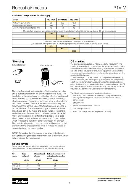
<strong>Robust</strong> air motors<strong>P1V</strong>-MChoice of components for air supplyMotor <strong>P1V</strong>-M020 <strong>P1V</strong>-M040 <strong>P1V</strong>-M060<strong>Air</strong> flow required, Nl/s 6,5 9,5 15,0<strong>Air</strong> flow required, Nl/min 390 570 900Min. internal diameter of pipe, mm 10 12 12Choice of air treatment unit: recommended min. air flow in litres/minute at 7.5 bar air supply and 0.8 bar pressure drop430630990Choice of valve: recommended min. air flow in Qn in litres/minute(Qn is the flow through the valve at 6 bar supply pressure and 1 bar pressure drop over the valve).4706901080SilencingExhaust silencerCentral silencerThe noise from an air motor consists of both mechanical noiseand a pulsating noise from the air flowing out of the outlet. Theinstallation of the motor has a considerable effect on mechanicalnoise. It should be installed so that no mechanical resonanceeffects can occur. The outlet air creates a noise level which canamount to 115 dB(A) if the air is allowed to exhaust freely intothe atmosphere. Various types of exhaust silencers are used toreduce this level. The most common type screws directly ontothe exhaust port of the motor, and a wide range of versions isavailable made of sintered brass or sintered plastic. Since themotor function causes the exhaust air to pulsate, it is a goodidea to allow the air to exhaust into some kind of chamber first,which reduces the pulsations before they reach the silencer.The best silencing method is to connect a soft hose to a centralsilencer with the largest possible area, to reduce the speed ofthe out-flowing air as far as possible.CE markingThe air motors are supplied as “Components for installation” – theinstaller is responsible for ensuring that the motors are installed safelyin the overall system. Parker Pneumatic guarantees that its productsare safe, and as a supplier of pneumatic equipment we ensure thatthe equipment is designed and manufactured in accordance with theapplicable EU directive.Most of our products are classed as components as defined byvarious directives, and although we guarantee that the componentssatisfy the fundamental safety requirements of the directives to theextent that they are our responsibility, they do not usually carry the CEmark. Nevertheless, most <strong>P1V</strong>-S motors carry the CE mark becausethey are ATEX certified (for use in explosive atmospheres).The following are the currently applicable directives:• Machinery Directive(essential health and safety requirementsrelating to the design and structure of machines and safetycomponents)• EMC Directive• Simple Pressure Vessels Directive• Low Voltage Directive• ATEX Directive (ATEX = ATmosphere EXplosive)NOTE! Remember that if a silencer is too small or is blocked,back pressure is generated on the outlet side of the motor, whichin turn reduces the motor power.Sound levelsSound levels are measured at free speed with the measuring instrumentpositioned 1 m away from the air motor, see the table below<strong>Air</strong> Free With exhaust Exhaust air removedmotor exhaust silencer with pipes to anotherroomdB (A) dB (A) dB (A)<strong>P1V</strong>-M020 107 97 74<strong>P1V</strong>-M040 107 98 80<strong>P1V</strong>-M060 107 99 829Parker Hannifin CorporationPneumatic Division - Europe