<strong>Robust</strong> air motors<strong>P1V</strong>-MCompressed air qualityThe <strong>P1V</strong>-M motor is equipped with vanes for intermittent lubricationfree operation as standard, which is the most commonapplication of air motors.Working pressureMax 7 barWorking temperature -30 °C to +100 °CMedium40 µm filtered, oil mist ordry unlubricated compressed airDry unlubricated compressed airIf unlubricated compressed air is used, the compressed airshould comply with the purity standards below in order to guaranteethe longest possible overall service life. If the unlubricatedcompressed air has a high water content, condensation formsinside the motor, causing corrosion in all internal components. Aballbearing can be destroyed in a remarkably short time if it comesinto contact with a single water droplet.For indoor use, we recommend ISO8573-1 purity class 3.4.1. Toachieve this, compressors must be fitted with aftercoolers, oilfilters, refrigerant air dryers and air filters.For indoor/outdoor use, we recommend ISO8573-1 purity class1.2.1. To achieve this, compressors must be fitted with aftercoolers,oil filters, adsorption dryers and dust filters.Oil mistIf oil mist is used (approx. 1 drop of oil per m³ of compressed air),the oil not only acts as a lubricant but also protects against corrosion.This means that compressed air with a certain water contentmay be used without causing corrosion problems inside the motor.ISO8573-1 purity class 3.-.5 may be used without difficulty.ISO 8573-1 purity classesQuality Contaminants Water Oilclass particle max. con- max. pressure max. consizecentration dew point centration(µm) (mg/m³) (°C) (mg/m³)1 0,1 0,1 -70 0,012 1 1 -40 0,13 5 5 -20 1,04 15 8 +3 5,05 40 10 +7 256 - - +10 -For example: compressed air to purity class 3.4.3This means a 5 µm filter (standard filter), dew point +3 ºC (refrigerantcooled) and an oil concentration of 1,0 mg oil/m³ (assupplied by a standard compressor with a standard filter).Service intervalThe first service is due after approximately 500 hours of operation.After the first service, the service interval is determined by the degreeof vane wear*. The table below shows new dimensions and theminimum dimensions of worn vanes.X<strong>Air</strong> motor Dimensions Minimum dimensionson new vanes on vaneX [mm]X [mm]<strong>P1V</strong>-M020 8,5 6,5<strong>P1V</strong>-M040 7,0 5,0<strong>P1V</strong>-M060 8,0 6,0The following normal service intervals should be applied to in order toguarantee problem-free operation in air motors working continuously atload speeds*.Intermittent lubrication-free operation of motors with standardvanesDuty cycle : 70%Max. duration of intermittent use : 15 minutesFiltration 40 µm :750 hours of operation*Filtration 5 µm :1 000 hours of operation*Continuous operation of motors with standard vanes, with lubricationDuty cycle :ContinuousQuantity of oil :1 drop per m³ of airFiltration 40 µm :1 000 hours of operation*Filtration 5 µm :2 000 hours of operation*NOTE! The grease in the planetary gearbox must be checked once ina year and be changed if necessary. (Molycote BR2+)* The specified hours of operation applywhen the motor is running at the speed correspondingto maximum power (load speed).This is approximately half free speed.If the motor operates at higher speeds, theservice interval is shorter.If the motor operates at lower speeds, theservice interval is longer.10Parker Hannifin CorporationPneumatic Division - Europe
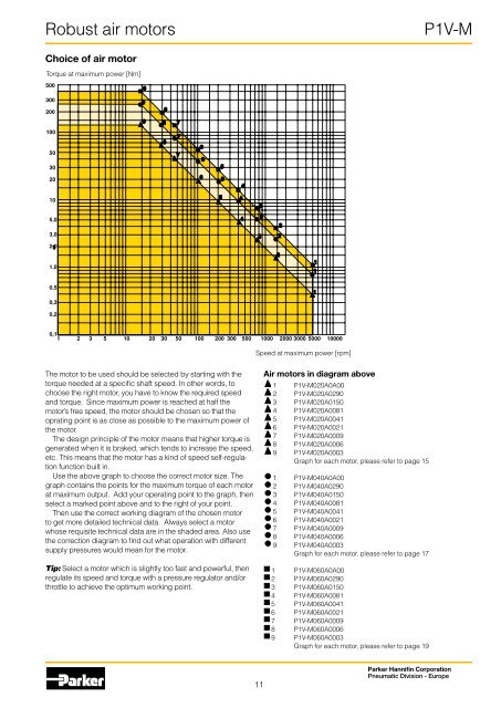
<strong>Robust</strong> air motors<strong>P1V</strong>-MChoice of air motorTorque at maximum power [Nm]500930020098100503098877766520654105435,03,0433222,0 11,02110,510,30,20,11 2 3 5 10 20 30 50 100 200 300 500 1000 2000 3000 5000 10000Speed at maximum power [rpm]The motor to be used should be selected by starting with thetorque needed at a specific shaft speed. In other words, tochoose the right motor, you have to know the required speedand torque. Since maximum power is reached at half themotor’s free speed, the motor should be chosen so that theoprating point is as close as possible to the maximum power ofthe motor.The design principle of the motor means that higher torque isgenerated when it is braked, which tends to increase the speed,etc. This means that the motor has a kind of speed self-regulationfunction built in.Use the above graph to choose the correct motor size. Thegraph contains the points for the maximum torque of each motorat maximum output. Add your operating point to the graph, thenselect a marked point above and to the right of your point.Then use the correct working diagram of the chosen motorto get more detailed technical data. Always select a motorwhose requisite technical data are in the shaded area. Also usethe correction diagram to find out what operation with differentsupply pressures would mean for the motor.Tip: Select a motor which is slightly too fast and powerful, thenregulate its speed and torque with a pressure regulator and/orthrottle to achieve the optimum working point.<strong>Air</strong> motors in diagram above1 <strong>P1V</strong>-M020A0A002 <strong>P1V</strong>-M020A02903 <strong>P1V</strong>-M020A01504 <strong>P1V</strong>-M020A00815 <strong>P1V</strong>-M020A00416 <strong>P1V</strong>-M020A00217 <strong>P1V</strong>-M020A00098 <strong>P1V</strong>-M020A00069 <strong>P1V</strong>-M020A0003Graph for each motor, please refer to page 151 <strong>P1V</strong>-M040A0A002 <strong>P1V</strong>-M040A02903 <strong>P1V</strong>-M040A01504 <strong>P1V</strong>-M040A00815 <strong>P1V</strong>-M040A00416 <strong>P1V</strong>-M040A00217 <strong>P1V</strong>-M040A00098 <strong>P1V</strong>-M040A00069 <strong>P1V</strong>-M040A0003Graph for each motor, please refer to page 171 <strong>P1V</strong>-M060A0A002 <strong>P1V</strong>-M060A02903 <strong>P1V</strong>-M060A01504 <strong>P1V</strong>-M060A00815 <strong>P1V</strong>-M060A00416 <strong>P1V</strong>-M060A00217 <strong>P1V</strong>-M060A00098 <strong>P1V</strong>-M060A00069 <strong>P1V</strong>-M060A0003Graph for each motor, please refer to page 1911Parker Hannifin CorporationPneumatic Division - Europe