A novel approach for automation of stereo camera calibration ... - PAR
A novel approach for automation of stereo camera calibration ... - PAR
A novel approach for automation of stereo camera calibration ... - PAR
- No tags were found...

Create successful ePaper yourself
Turn your PDF publications into a flip-book with our unique Google optimized e-Paper software.
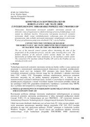
Table 2 shows that acquisition <strong>of</strong> sharp images duringmanual positioning <strong>of</strong> the <strong>calibration</strong> target is practicallyimpossible <strong>for</strong> micro scale observation and very difficultand time-consuming process <strong>for</strong> larger field <strong>of</strong> views.Proposed system guarantees the optimal quality <strong>of</strong> inputimages <strong>for</strong> <strong>calibration</strong> by implemented sequence <strong>of</strong> rotations.Tab. 2. Navitar Zoom 6000 Field <strong>of</strong> View Matrix [12]Tab. 2. Macierz pola widzenia obiektywu Navitar Zoom 6000ParameterDOF[mm]FOV [mm]Mag.WD = 356 mm,0.25 attachment,0.67X TelescopeLens system setupWD = 113 mm0.75X attachment,3.5X TelescopeLow 13.89 1.73High 1.54 0.18Low 93.62 5.98High 14.66 0.93via GigE Vision standard. For the best per<strong>for</strong>mance <strong>of</strong><strong>calibration</strong> algorithm, the histogram analysis <strong>of</strong> acquiredimages is done to guarantee the optimal contrast value.14Fig. 7. Camera positioning module: 1 – piezo actuator, 2 – zoomDC servo with encoder, 3 – focus DC Servo with encoder,4 – CCD <strong>camera</strong>Rys. 7. Moduł pozycjonowania kamer: 1 – piezonapęd, 2 – silnikDC z enkoderem do regulacji powiększenia, 3 – silnik DCz enkoderem do regulacji ostrości, 4 – kamera CCD23Be<strong>for</strong>e starting the <strong>calibration</strong> procedure, it is required toadjust <strong>camera</strong> orientations, set the optimal focus positionin the motorized lens system and set the optimal lightingconditions. In order to adjust <strong>camera</strong> orientations thatwere previously set manually by an operator, the visualfeedback system is applied (fig. 6).Fig. 6. Visual feedback system <strong>for</strong> <strong>camera</strong>s orientation adjustmentFig. 6. Wizyjna pętla sprzężenia zwrotnego systemu korekcjiorientacji kamerThe laser beam is used to project the cross shape targetpattern. The visual tracking system <strong>for</strong> both <strong>camera</strong>sis applied to detect vertical and horizontal lines.An implemented algorithm is used to adjust <strong>camera</strong> orientationsto point directly in the centre <strong>of</strong> target cross. Thesecond important step to validate the <strong>calibration</strong> procedureis to set the optimal focus value. The implementedalgorithm is based on 2D Discrete Fourier Trans<strong>for</strong>mation.Navitar’s motorized lens system uses DC Servos withEncoder (fig. 7) that are controlled via RS-232 port in arange up to 3000 steps. Magnetic Hall-Effect sensors areused to reference position location. Starting from the lowposition limit <strong>of</strong> DC servo, the maximum focus value issearched and saved as a system parameter. The last stagebe<strong>for</strong>e starting the <strong>calibration</strong> procedure is to adjust theoptimal lighting conditions <strong>for</strong> detection <strong>of</strong> the <strong>calibration</strong>target. LED ring illuminators with the illuminance <strong>of</strong> ca.18 klux at the distance <strong>of</strong> ca. 300 mm from the samplewere used. Exposure time <strong>of</strong> Basler <strong>camera</strong>s is controlledImages with lower contrast results in longer executiontime <strong>of</strong> implemented algorithm <strong>for</strong> circular grid detection.The <strong>calibration</strong> procedure requires several images <strong>of</strong> <strong>calibration</strong>target in different orientations. Images acquiredfrom both <strong>camera</strong>s are analyzed during the <strong>calibration</strong>process. The whole process is automated and doesnot require any action from an operator. Calibration targetpoints are detected autonomously by the implementedalgorithm using full resolution (5 Mpx) images. The <strong>calibration</strong>process is done using a circular grid containing 65control points. Developed s<strong>of</strong>tware takes the advantagefrom multithreading which allowed <strong>for</strong> the implementation<strong>of</strong> fast executing code. Execution time is less than 2 minuteswith the RMS error value below 0.2.4.ConclusionsThe proposed method is dedicated <strong>for</strong> <strong>stereo</strong>vision system<strong>for</strong> fatigue process monitoring. A condition <strong>of</strong> scalability isfulfilled by designed <strong>calibration</strong> module that allows use <strong>of</strong>a set <strong>of</strong> a wide range <strong>of</strong> size planar <strong>calibration</strong> targets.There<strong>for</strong>e, it is possible to analyze the 3D surface inboth a micro and macro scale. Ultra-high resolution piezoactuatorsare used <strong>for</strong> <strong>automation</strong> <strong>of</strong> the <strong>calibration</strong> procedure.The automated procedure avoids positioning <strong>calibration</strong>starget out <strong>of</strong> focus, which is important due tolimited depth <strong>of</strong> field <strong>of</strong> the applied vision system. Theproposed solution reduces <strong>calibration</strong> time and guaranteesrepeatability <strong>of</strong> the <strong>calibration</strong> results below, thereprojection error assumed. Implemented algorithm is fullyautonomous. No specialised knowledge or actions is requiredfrom an operator; that makes the <strong>calibration</strong> processstraight<strong>for</strong>ward compared to other existing solutions.Further work will focus on optimization <strong>of</strong> the system,which includes research on defining the finest <strong>calibration</strong>target. Both the size <strong>of</strong> the pattern and shape <strong>of</strong> controlpoints will be considered.Pomiary Automatyka Robotyka nr 2/2013237
NAUKAAcknowledgmentsScientific work created within the framework <strong>of</strong> the“Innovative Systems <strong>of</strong> Technical Support <strong>for</strong> SustainableDevelopment <strong>of</strong> Economy” Strategic Programme withinthe Innovative Economy Operational Programme.References1. Wang Y.-Q., Sutton M.A., Ke X.-D., Schreier H.W.,Reu P.L., Miller T.J., On Error Assessment in StereobasedDe<strong>for</strong>mation Measurements. Part I: TheoreticalDevelopments <strong>for</strong> Quantitative Estimates, Strain, 2009,Vol. 45, 160–178.2. Dang T., Continuous Stereo Self-Calibration by CameraParameter Tracking, “Transactions on image processing”,Vol. 18, No. 7, 2009, 1536–1550.3. Giesko T., Dual-<strong>camera</strong> vision system <strong>for</strong> fatigue monitoring,Materials Science Forum, Vol. 726, 226–232.4. Tsai R.Y., A Versatile Camera Calibration Technique<strong>for</strong> High-Accuracy 3D Machine Vision Metrology UsingOff-Shelf TV Cameras and Lenses, IEEE “Journal onRobotics and Automation”, 1987, Vol. 4, 323–344.5. Liangfu L., Zuren F, Yuanjing F., Accurate Calibration<strong>of</strong> Stereo Cameras <strong>for</strong> Machine Vision, “Journal <strong>of</strong>Computer Science & Technology”, 2004, 147–151.6. Urqunhart C.W., Siebert J.P., McDonald J.P., FryerR.J., Active Animate Stereo Vision, The British MachineVision Conference, Surrey, 1993, 75–84.7. Zollner H., Sablatnig R., Comparison <strong>of</strong>Methods <strong>for</strong> Geometric Camera Calibration using PlanarCalibration Targets, 28 th Workshop <strong>of</strong> the AustrianAssociation <strong>for</strong> Pattern Recognition, Hagenberg, 2004,237–244.8. [http://docs.opencv.org] – OpenCV v.2.4.3.9. Weng J., Cohen P, Herniou M., Camera Calibrationwith Distortion Models and Accuracy Evaluation,“IEEE Transactions on Pattern Analysis and MachineIntelligence”, 1992, 967–970.10.Bradley D., Heidrich W., Binocular CameraCalibration Using Rectification Error, Canadian Conferenceon Computer and Robot Vision, 2010.11.Schmalz Ch., Forster F., Angelopoulou E.,Camera Calibration: Active versus Passive Targets,“Optical Engineering”, Vol. 50, No. 11, 2011.12.[http://www.navitar.com]13.Ouellet J.N., Hebert P., Developing Assistant Tools <strong>for</strong>Geometric Camera Calibration: Assessing the Quality <strong>of</strong>Input Images, ICPR 2004, [in:] Proceedings <strong>of</strong> the 17 thInternational Conference, Vol. 4, 2004, 80–83.14.Sharpe W.N. ,Springer Handbook <strong>of</strong> Experimental SolidMechanics, Springer, 2008, 589-597.15.Yan J.H., Sutton M.A., Deng X., Wei Z., Mixed-modecrack growth in ductile thin-sheet materials under combinedin-plane and out-<strong>of</strong>-plane loading, “InternationalJournal <strong>of</strong> Fracture”, Vol. 14, No. 4, 2009, 297–321.Automatyzacja procesu kalibracji systemu<strong>stereo</strong>wizyjnegoStreszczenie: Zagadnienie kalibracji kamer w systemach<strong>stereo</strong>wizyjnych było w ostatnich latach podejmowane przezwielu badaczy. Głównym celem tego procesu jestwyznaczenie trans<strong>for</strong>macji pomiędzy współrzędnymi 3D punktóww układzie globalnym i odpowiadającymi im współrzędnymipikselowymi 2D na płaszczyźnie obrazowania kamer. Corazwiększa liczba obszarów, w których zastosowanie znajdująsystemy <strong>stereo</strong>wizyjne, doprowadziła do specjalizacjiwykorzystywanych w nich metod kalibracji kamer. Aktualnie stosowanesą różnorodne wzorce kalibracyjne, a także metodysamokalibracji kamer. W artykule przedstawiony został autorskizautomatyzowany system kalibracji kamer dedykowany dla systemu<strong>stereo</strong>wizyjnego, umożliwiającego monitorowanie procesówdestrukcji materiałów na maszynie wytrzymałościowej. Dla zapewnieniamożliwości przeprowadzenia badań zarówno w skalimikro jak i makro, system ten wyposażony jest w zmotoryzowaneobiektywy, umożliwiające regulację zbliżenia i ostrości.Prezentowany system kalibracji poprzez zastosowanie mechatronicznegoukładu pozycjonowania oraz odpowiedniego typoszereguwzorców płaskich, zapewnia kalibrację kamer w pełnymzakresie obserwacji. Rozwiązanie to umożliwia automatyzacjęoraz gwarantuje powtarzalność procesu kalibracji.Słowa kluczowe: <strong>stereo</strong>wizja, kalibracja, badania wytrzymałościowePiotr Garbacz, MScAssistant at the Institute <strong>for</strong> SustainableTechnologies – National ResearchInstitute in Radom. He received Masterdegree in robotics from WarsawUniversity <strong>of</strong> Technology in 2010. Heworks in the area <strong>of</strong> vision systems androbotics.e-mail: piotr.garbacz@itee.radom.plWojciech Mizak, MScAssistant at the Institute <strong>for</strong> SustainableTechnologies – National ResearchInstitute in Radom. Responsible <strong>for</strong>prototypes <strong>of</strong> mechanical andmechatronics design in the field <strong>of</strong>automatic optical inspection,thermography and erosive wear testing.e-mail: wojciech.mizak@itee.radom238