Download - Buderus
Download - Buderus
Download - Buderus

You also want an ePaper? Increase the reach of your titles
YUMPU automatically turns print PDFs into web optimized ePapers that Google loves.
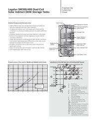
6Collector Installation6.1 Preparing to install the collectorsBefore beginning the installation on the roof,preassemble the end caps on the ground to make workon the roof easier.To secure the solar hoses, the Hose clamp must beequipped with the locking ring.SYSTEM DAMAGECAUTION!from leaks in the solar hoses. The hose clamp (Fig. 33, [2]) must bepositioned correctly before pulling thehandle (Fig. 33, [1]) Subsequentloosening requires using pliers andmay cause a leak.1Fig. 33Hose clamp with locking ring, also shown installed tothe pre-assembled dummy plug263043965.38-1.SDCAUTION!RISK OF INJURYDon't pull the locking ring unless the hoseclamp has been positioned at its finallocation.216.1.1 Reverse-return pipingCollectors are piped in reverse-return. This ensures thateach collector receives the same volume rate of flow(Fig. 34).12NOTICEThe supply line can be installed to the topright (Fig. 34) or left (Fig. 35). In thismanual, the supply line is shown on theright.The collectors must be installed with the collector sensorwell (Fig. 35, [1]) at the top.NOTICEIf an automatic air-vent valve (accessory)will be installed at the highest point of thesystem, pitch the supply and return pipestoward the top.63043965.39-1.SDFig. 34 Hydraulic connection – right-hand supply line1 Solar hose 4 in (95 mm)2 2 in (55 mm) solar hose and dummy plug3 Supply line4 Return line143Fig. 35Hydraulic connection – left-hand flow line63043965.19-1.SD28Logasol SKN 3.0 - We reserve the right to make any changes due to technical modifications.