Download - Buderus
Download - Buderus
Download - Buderus

You also want an ePaper? Increase the reach of your titles
YUMPU automatically turns print PDFs into web optimized ePapers that Google loves.
Installation ManualSolar ThermalFlat Plate Collectors6720614825.02-1.SDLogasol SKN 3.0Mounting System forSloped RoofsFor ContractorsPlease read carefully priorto installation.6 720 614 825 ( 02/2010 ) US/CA
General 11 GeneralThis chapter details which technical rules andregulations apply to this installation.NOTICEObserve all standards and guidelinesapplicable to the installation andoperation of this system in your country.Installations must be made in accordancewith all codes and regulations applicableto the installation site.Lightning protectionIf the solar equipment protrudes above the roof ridge orthe building height (installation height) exceeds 66 ft(20 m), it is recommended to have lightning arrestorsinstalled on the tallest equipment including the solarcollectors.Logasol SKN 3.0 - We reserve the right to make any changes due to technical modifications. 3
2Specifications2 SpecificationsSKN 3.0Certificates0036DINLengthWidthDepthTab. 1Specifications81-1/2 in(2,070 mm)45-1/8 in(1,145 mm)3-1/2 in(90 mm)1 inClearance between collectors(25 mm)0.2 galAbsorber contents, Portrait version V f (0.9 l)0.33 galAbsorber contents, Landscape version V f (1.25 l)26 ft²Gross absorber surface area A G (2.41 m²)Net absorber surface areaNet weight, Portrait versionNet weight, Landscape versionPermissible operating pressure of thecollectormmp max24.29 ft²(2.26 m²)91 lbs(41 kg)93 lbs(42 kg)87 psi(6 bar)4Logasol SKN 3.0 - We reserve the right to make any changes due to technical modifications.
Safety 33 SafetyThis chapter explains the meaning of the notes you willfind in this manual and provides general safetyinstructions for safe and trouble-free operation.You will find the installation-specific safety and usernotes next to the appropriate installation steps.Carefully read the safety instructions beforecommencing the installation.Severe injury and even death, as well as propertydamage and environmental damage, may follow if youignore safety instructions.About this manualThis installation manual contains important informationfor the safe and intended installation of sloped roofmounted systems as well as plumbing connections.The illustrations in this manual show the portraitcollectors. Instructions for landscape collectors are thesame as for portrait unless stated otherwise.These technical documents should be retained in a safeplace.The activities described in the installation manualassume expertise based on completed vocationaltraining in plumbing. Only carry out these installationsteps if you possess these skills. Hand these installation instructions to the buildingowner. Explain to the customer the function and operation ofthe related devices.3.1 Intended useInstall components only on roofs with sufficient strengthand capacity. Take the additional roof load per roof rack,including solar collector, into consideration. If necessary, ask a structural engineer for assistance.This mounting system holds the solar thermal collectors(portrait and landscape) on pitched roofs with a slope of25° to 65°. The collectors can be installed on differentroof surfaces, including asphalt shingle, ceramic tile,slate, composite shingle, corrugated or standing seamor other metal roofs with slopes between 5° and 65°.Application conditionsThe mounting system is suitable for a max. standardsnow load of 42 lbs/sqft (2.0 kN/m 2 ) and an installationheight of max. 66 ft (20 m). Using appropriateaccessories, the system can be used for a max.standard snow load of 65 lbs/sqft (3.1 kN/m 2 ) and amax. installation height of 328 ft (100 m). SeeChapter 5.7 "Installing high load rails (accessory)".Do not attach any other devices, e.g. antennas, tocollector racks.Logasol SKN 3.0 - We reserve the right to make any changes due to technical modifications. 5
3Safety3.2 Guideline of NoticesTwo levels of safety are identified by the followingsymbols:WARNING!CAUTION!DANGERDenotes a possible severely dangeroussituation where, without proper caution,bodily injury or loss of life may result.RISK OF INJURY/SYSTEM DAMAGE/BUILDING DAMAGEIdentifies a possible dangerous situationthat can lead to mild to moderate bodilyinjury or property damage.Additional symbol for designating user notes:NOTICEApplication comment for optimum use ofequipment and adjustment as well asuseful information.3.3 Please observe these safetyinstructionsWARNING!CAUTION!RISK TO LIFEfrom a fall or falling tools and parts. Take appropriate action to preventaccidents when working on roofs. While working on the roof, take allnecessary precautions againsta possible fall. Always wear protective clothing anduse your personal protectiveequipment (PPE). If you are not comfortable working on aladder, a lift, or the roof, hire a roofingcontractor to install the equipment. After completing an installation alwaysverify that all components are installedaccording to the instructions and aresecurely attached.RISK OF INJURYPersonal injury and system faults canresult from altered construction. Never modify structural elements. Never drill additional holes. Never attach non-system relatedcomponents (e.g. antennas).CAUTION!CAUTION!CAUTION!CAUTION!CAUTION!CAUTION!CAUTION!CAUTION!RISK OF INJURYSolar system components can becomevery hot even when a system isdecommissioned. Always wear protective clothing andsafety equipment. Cover the collector (collector coversare available as an accessory) duringinstallation to prevent hightemperatures resulting from solarradiation.Observe maximum load and distance fromedges before installing the substructuresupports to the roof. If necessary, consult astructural engineer to determine if thestructure is suitable for installing solarcollectors, including expected snow andwind loads.Solar pipes and solar fluid can causesevere burns. Extreme caution must betaken when a system is in stagnation.SYSTEM DAMAGEAvoid scratching or sudden shocks to theglass of a solar panel. Never step or walkon collectors.Never braze or solder in close proximity ofa solar panel.Install a heat exchanger to separate poolwater or potable water from the collectorsystem.The use of heat transfer fluid “Tyfocor L,Tyfocor LS and Tyfocor L "G" ” is stronglyrecommended.For more detailed information aboutsuitable solar heat transfer fluids refer tothe installation instruction of the KS pumpstations.This system is not suitable for drain backinstallations. Only closed loop pressurizedsystems are permitted.6Logasol SKN 3.0 - We reserve the right to make any changes due to technical modifications.
Before installation 44 Before installation4.1 General notesNOTICEIt is recommended to consult a roofingcompany, as they are experienced inworking on roofs and are equipped withthe necessary personal safety equipment.Roofers also are experienced withattaching equipment to the roof andmaking proper penetrations.Make yourself familiar with the on-site conditions andlocal regulations before commencing the installation.Check the delivery for completeness and perfect condition. the roof structure for sufficient strength and possibledamage (e.g. leaks). the building height and determine the type andnumber of attachment points required the optimal arrangement of the solar collectors. Takeinto consideration the orientation of the buildingtoward the sun, any tall trees, adjacent buildings,building features, etc. where the penetration(s) into the building envelopeare located and arrange the collector arrayaccordingly.Fig. 1General overview of two collectors63043965.02-1.SD if the collector array can be arranged symmetricallywith the building and building features.NOTICEOnly use OEM components and replaceany defective or damaged partsimmediately.NOTICEIt is recommended to consult aprofessional roofer if roof repairs arenecessary. Have the work completedbefore installing the solar equipment.Logasol SKN 3.0 - We reserve the right to make any changes due to technical modifications. 7
4Before installation4.2 Component description4.2.1 Collector racksThe collectors are attached to horizontal rails that aremounted on roof hooks or standoffs. A variety ofattachment methods are available to match different rooftypes and surfaces.81 2 3345Fig. 27663043965.03-1.SDMounting system for 2 collectors – 1 basic system, 1 extension system and 2 sets of roof hooks (hooks for tile roofs shown)Basic mounting system for each collector arrayincluding the first collector (Fig. 2):Extension mounting system for each additionalcollector (Fig. 2):1 Horizontal rail 2 × 1 Horizontal rail 2 ×3 Single-sided collector clamp 4 × 2 Double-sided collector clamp 2 ×7 Collector hanger 2 × 7 Collector hanger 2 ×8 M8 nut 4 × 6 Rail connector 2 ×8 M8 nut 4 ×Roof hook for tile roofs, per collector (Fig. 2):4 Roof hook for tile roofs, adjustable 4 ×5 Sliding nut 4 ×NOTICEFor higher snow and wind loads,additional horizontal rails and roof hooksmay be needed.8Logasol SKN 3.0 - We reserve the right to make any changes due to technical modifications.
Before installation 44.2.2 Hydraulic connectionFor the hydraulic connections the connection kit isneeded. The parts are included in two of the cornerprotectors of each collector's packaging.4 51 2 338765463043965.04-1.SDFig. 3Connection kit and connection setConnection kit, per collector array (Fig. 3)1 Hose clamp (1 x spare) 5 × 5 Solar hose, length 2 in (55 mm) 2 ×2 Collector connection hose 2 × 6 Compression fitting for collector sensor 1 ×3 Solar hose, length 40 in (1000 mm) 2 × 7 #5 Allen wrench 1 ×4 Dummy plug 2 × 8 Hose pipe adapter R3/4 with 5/8" compression ring 2 ×Connection set between the collectors, for eachcollector (in two of each collector's protectivecorners, Fig. 4)1 Hose clamp 4 ×2 Collector connection hose, length 4 in (95 mm) 2 ×21Fig. 463043965.05-1.SDTwo of the four protective corners of each collectorcarry parts for interconnecting collectorsLogasol SKN 3.0 - We reserve the right to make any changes due to technical modifications. 9
4Before installation4.3 Other equipment– Level– Rope– High head filling pump– Personal protective equipment for on the roof– Pipe insulation with UV protective coating– Scaffolding– Ladder– Bucket truck or scissor liftNOTICEWhen installing the roof mounting set andwater connection, the only tool you willneed is the size 5 Allen wrench from theconnection kit plus some adjustable pipewrenches.4.4 Transport and storageAll components are protected by transport packaging.NOTICEDispose of the transport packaging in anenvironmentally friendly manner.Transport protection for collector connectionsThe collector connections are protected against damageby rubber caps.SYSTEM DAMAGEWARNING!Storagefrom damaged gaskets. Do not remove the rubber caps (Fig. 5, [1]) until immediately prior toinstallation.1The collectors must be stored in dry conditions.NOTICEDo not store collectors outside withoutprotection from the weather. Thepackaging is not designed to be allweather proof.Protect the collectors using a tarp duringtransport in wet weather in an open truck.Fig. 5Rubber caps on collector connections63043966.05-1.SD10Logasol SKN 3.0 - We reserve the right to make any changes due to technical modifications.
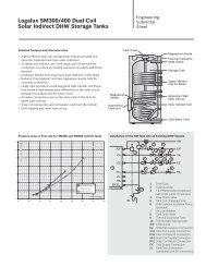
Before installation 44.5 Technical documentationThe solar thermal system consists of variouscomponents (Fig. 6). Installation, operation andmaintenance documentation is provided for eachcomponent. Accessories may be accompanied bya separate document.1 Collector: instructions for roof installationare enclosed with the connection kit2 Pump station: instructions enclosed with thepump station3 DHW storage tank: instructions enclosed withthe DHW storage tank321Fig. 663043965.07-1.SDSolar thermal system components and technicaldocumentationLogasol SKN 3.0 - We reserve the right to make any changes due to technical modifications. 11
4Before installation4.6 Determining space required on roofPlease observe the following minimum space requirements for roof stability reasons, safe access during installation, and to reduce wind load.Dimension A and BArea required for the collector array.Dimension CHOn tile roofs keep a minimum clearance of two rows oftiles to the ridge, dormers, a chimney, or other buildingfeatures. On asphalt shingle roofs, metal roofs, orsimilar, keep at least 3 feet (1m) clearance to the ridge,to dormers, a chimney, or other building features.Dimension DKeep clear of roof overhangs on the gable end of theGhouse.Dimension EMinimum 12 in (30 cm) for making the connection in theattic.Fig. 7 Clearances to be observedDimension FMinimum 16 in (40 cm) for making the connection in theattic.NOTICEIf access to the roof is limited, considerinstalling the air vent in the attic. Ensurethat there is sufficient room and clearancein the attic to position this air vent abovethe top of the collectors.63043965.09-1.SDDimension GKeep at least 3 feet (1 m) clearance from roof edges andoverhangs including the gable wall thickness.Dimension HDimension H is 75 in (1,900 mm) for portrait collectors(39.4 in (1,000 mm) for landscape collectors) and is theminimum distance from the upper edge of the collectorto the lower profile rail, which is installed first.Space requirements for portrait collectors:Space requirements for landscape collectors:sNumber of collectors Dimension A Dimension B Number of collectors Dimension A Dimension B2 91 in (2.32 m) 81 1/2 in (2.07 m) 2 164 in (4.17 m) 45 5/16 in (1.15 m)3 137 in (3.49 m) 81 1/2 in (2.07 m) 3 266 in (6.26 m) 45 5/16 in (1.15 m)4 183 in (4.66 m) 81 1/2 in (2.07 m) 4 329 in (8.36 m) 45 5/16 in (1.15 m)5 230 in (5.83 m) 81 1/2 in (2.07 m) 5 411 in (10.45 m) 45 5/16 in (1.15 m)6 278 in (7.06 m) 81 1/2 in (2.07 m) 6 494 in (12.55 m) 45 5/16 in (1.15 m)7 322 in (8.17 m) 81 1/2 in (2.07 m) 7 577 in (14.64 m) 45 5/16 in (1.15 m)8 368 in (9.34 m) 81 1/2 in (2.07 m) 8 659 in (16.74 m) 45 5/16 in (1.15 m)9 414 in (10.51 m) 81 1/2 in (2.07 m) 9 733 in (18.61 m) 45 5/16 in (1.15 m)10 460 in (11.68 m) 81 1/2 in (2.07 m) 10 824 in (20.93 m) 45 5/16 in (1.15 m)Tab. 2 Space requirement for portrait collectors Tab. 3 Space requirement for landscape collectors12Logasol SKN 3.0 - We reserve the right to make any changes due to technical modifications.
Installing roof hooks and horizontal rails 55 Installing roof hooks and horizontal railsRISK TO LIFEWARNING!Use appropriate personal protectiveequipment whenever on a ladder, lift,or the roof.RISK OF INJURYWARNING!from a fall or falling parts. Take appropriate action to preventaccidents when working on roofs. Always wear your personal protectiveclothing and safety equipment.Four types of roof attachments are offered: Adjustable roof hook ( 5.2, 5.3):for installation on "S"-tile roofs, barrel tile roofs, andsimilar roof tiles; Hanger bolt ( 5.4):for corrugated sheet roofs, asphalt shingle roofs, flatshingle roofs, slate roofs, mission style pan roofs,and similar roofing materials; Roof hooks ( 5.5):for asphalt shingle, slate, or composite shingle roofs,and similar roofing materials; For metal roofs the hanger bolt ( 5.6) can be usedor in case of a sufficiently strong standing seam, aspecial seam clamp is recommended. Pleasecontact <strong>Buderus</strong> for details.Fig. 8WARNING!Installed horizontal rails for two collectorsPROPERTY DAMAGE63043965.10-1.SDEnsure the building substructure iscapable of carrying the load of the panelsincluding the required snow and windloads. Only attach to framing that isproperly supported.Do not connect to less than 2x6 framing.Follow the local building code and usebest practice methods.NOTICEObserve all national and local safetyregulations, as well as the safetyinstructions in this manual when workingon roofs.NOTICEAlways use personal protectiveequipment, and ensure it is in goodworking order.NOTICETake measures to protect the roofmembrane when working on the roof. It isrecommended to consult a professionalroofer to ensure the membrane is notdamaged.Logasol SKN 3.0 - We reserve the right to make any changes due to technical modifications. 13
5Installing roof hooks and horizontal rails5.1 Rail and hook spacingUse the dimensions given as guidelines for a properinstallation.NOTICEOn tile roofs the tile valleys determine thetrue distance between the roof hooks.Distances between roof attachmentsEvery horizontal rail is fastened using two roofattachments (Fig. 9) per collector. See the table for theapproximate distance between the attachment points.zxInstallationtypeportraitlandscapeTab. 4Distance w Distance x Distance zapprox. 46 in(1, 170 mm)approx.82-5/16 in(2,090 mm)24 – 51 in(610 –1,030 mm)60 – 77 in(1,520 –1,950 mm)Distance between attachment points6-5/8 – 25-1/4 in(170 – 540 mm)6-5/8 – 21-1/4 in(170 – 540 mm)Fig. 9Distance between roof hooks63043965.11-1.SDNOTICEDistances x and z should always beapproximately equal to distance w.Distances between horizontal railsSet the distance between the top and bottom profile rails(Fig. 10) according to Tab. 5.CollectortypeDistance yfromtoportrait 52 in (1320 mm) 67 5/16 in (1710 mm)landscape 23 5/8 in (600 mm) 32 5/16 in (820 mm)Tab. 5 Distance (center to center) between bottom and topraily63043965.12-1.SDFig. 10Distance between profile rails14Logasol SKN 3.0 - We reserve the right to make any changes due to technical modifications.
Installing roof hooks and horizontal rails 55.2 Adjustable Roof Hooks for Tile RoofsStep one is to install all roof hooks according to theguidelines shown in tables 4 and 5 on page 14.NOTICEAvoid modifying the roof surface and takecare not to compromise a roofingmembrane. Consult a professional rooferto ensure proper installation.NOTICEIn the case of tiles laid in mortar, leaveclearances of at least 2 rows of tiles fromany ridge or building feature.NOTICEIf roof hooks cause tiles to ride too high ornot fit properly, the conflicting areas of thetiles may have to be ground down toensure a secure fit.Fig. 11Installed roof hooks for two collectors63043965.13-1.SDSYSTEM DAMAGECAUTION!from gradual loosening of the hex-nut onthe roof hook. When the nut is tightened,adhesive is activated which bonds thejoint securely after one hour. If the roof hook requires adjustmentafter this time the adhesive may becompromised. It must then be securedon-site (e.g. lock washer).Logasol SKN 3.0 - We reserve the right to make any changes due to technical modifications. 15
5Installing roof hooks and horizontal rails5.2.1 Attaching roof hooks to the substructureNOTICERoof hooks must be attached to thebuilding substructure. Sheathing alonewill not support the load of the solarcollectors. Minimum 2x6 framing requiredto attach the roof hooks to. Follow thelocal building code and use best practicemethods.312NOTICEWith some roof coverings it may benecessary to suspend the roof hook usinga board or shims (Fig. 13, [6]) to get theupper part of the roof hook to rest on topof the tile. Loosen the long hex-nut (Fig. 12, [2]) anddisassemble the unit. Insert bolt into upper hole (Fig. 12, [3]). Reassemble with the L-shaped piece (Fig. 12, [4])facing away and down. Do not tighten the nut (Fig. 12, [2]) until the hook isinstalled and properly adjusted.45Fig. 12 Adjusting the roof hook1 Lower part of roof hook2 Long hex-nut3 Upper hole for fastening the lower part4 L-shaped attachment piece5 Cut off if necessary63043965.16-1.SDCAUTION!SYSTEM DAMAGEfrom failure of the roof hook if the bolt isnot positioned in the upper hole, resultingin uneven load distribution. The roof hooks must be positioned in tile valleys anddirectly bolted to the building substructure withsufficient capacity to carry the load of the solarsystem including required snow and wind loads(Fig. 13, [3]).6451Allow for expansion and contraction by keeping someclearance along the upper edge of the tile (Fig. 13, [4]). Push the L-shaped part of the roof hook down until itlies flat on the sheathing or on the board/shim ifneeded (Fig. 13, [6]).NOTICEThe toothed washer (Fig. 13, [5]) mustgrip the teeth on the lower part of the roofhook. Tighten the long hex-nut (Fig. 13, [1]). To do this,insert the size 5 Allen wrench into the hole in the hexnutand turn. Using suitable screws (Fig. 13, [2]), secure the L-shaped part of the roof hook to the buildingsubstructure. The sheathing alone will not offersufficient support.363043965.17-1.SDFig. 13 Roof hook installed (some tiles have been removedfor a better view)1 Long hex-nut2 Screw for fastening roof hook3 Front brace4 Adjust the tile as necessary to install the roof hook5 Toothed washer6 Sheathing, or board/shim if needed3216Logasol SKN 3.0 - We reserve the right to make any changes due to technical modifications.
Installing roof hooks and horizontal rails 55.3 Adjustable Roof Hooks on FlatShingle and Slate RoofsNOTICEIt is recommended to consult a rooferwhen installing on shingle or slate roofs.Ensure the required distances (w, x and y) between theroof hooks as detailed in (Tab. 4 and Tab. 5, page 14).Remove the needed number of shingles/tiles to gainaccess to the sheathing where to mount the roof hook(Fig. 14, [1]).The roof hooks must be directly bolted to the buildingsubstructure with sufficient capacity to carry the load ofthe solar system including required snow and windloads.Fig. 14Remove the needed number of shingles/tilesPreparing roof hookBefore installing, the lower part must be moved to thecorrect position. Loosen the long hex-nut (Fig. 15, [2]) anddisassemble the unit. Insert bolt into upper hole (Fig. 15, [3]). Reassemble with the L-shaped piece (Fig. 15,center) facing away and down. Do not tighten the nut (Fig. 15, [2]) until the hook isinstalled and properly adjusted.SYSTEM DAMAGE3124CAUTION!from failure of the roof hook if the bolt isnot positioned in the upper hole, resultingin uneven load distribution.Fig. 15 Repositioning lower part of roof hook1 L-shaped attachment piece2 Long hex-nut3 Upper hole4 Cut off if necessary63043965.16-1.SDLogasol SKN 3.0 - We reserve the right to make any changes due to technical modifications. 17
5Installing roof hooks and horizontal railsInstalling the roof hook Push the lower part of the hook down until it lies flaton the sheathing (Fig. 16, [1]).NOTICEThe toothed washer (Fig. 16, [2]) mustengage with the teeth on the lower part ofthe roof hook. Tighten the long hex-nut (Fig. 17, [1]). To do this,insert the size 5 Allen wrench into the hole in the hexnutand turn. Using suitable screws, attach the upper part of theroof hook (Fig. 18) through the sheathing to thebuilding substructure.Fig. 16Installed roof hook If necessary cut adjacent shingles/tiles (Fig. 18, [1])to size (dashed line, Fig. 18, [2]).Fig. 17 Toothed washer must engage with the toothed hookwhen tightening the nut1 Long hex-nut2 Toothed washer21Fig. 18Tiles/shingles may have to be trimmed to size18Logasol SKN 3.0 - We reserve the right to make any changes due to technical modifications.
Installing roof hooks and horizontal rails 55.4 Hanger Bolt InstallationIt is recommended to consult a roofer when installing oncorrugated roofs.WARNING!RISK TO LIFEfrom inhalation of fibers containingasbestos. Work with materials containingasbestos must only be carried out bytrained and certified professionals.Hanger bolts are designed for asphalt shingle roofs, flatshingle roofs, slate roofs, corrugated sheet roofs,mission style pan roofs, and similar roofing materials.The following procedure describes installation on acorrugated roof. Installation on flat roof surfaces shouldbe performed in a similar fashion.Standard delivery (Fig. 19):1 M8 screw 4 ×2 Attachment block 4 ×3 M12 nut 4 ×4 Washer 4 ×5 Gasket 4 ×6 M12 stud 4 ×The number of hanger bolts per panel must be based onthe required snow and wind load. Minimum four (4) boltsper panel.On corrugated roofs, the peaks in the corrugationdetermine the true distance between the post screws.Maintain the required distances (w, x and y) betweenhanger bolts as shown in Tab. 4 and Tab. 5, page 14.SYSTEM DAMAGEdue to an insufficient substructure.Fig. 19 Hanger boltAdditional tools required– Cordless screwdriver– Tape measure– Wood drill bit 1/4" (6 mm)– Metal drill bit, 1/2" (13 mm)– Wrench size 15 and 1912345663043965.22-1.SDCAUTION! Ensure the building substructure iscapable of carrying the load of thepanels including the required snowand wind loads. Only attach to framing that is properlysupported. Do not install hanger bolts in less than2x6 framing. Follow the local building code and bestpractice when installing hanger bolts.Logasol SKN 3.0 - We reserve the right to make any changes due to technical modifications. 19
5Installing roof hooks and horizontal railsInstalling the hanger boltsNOTICEWith corrugated roofs it is recommendedto install the hanger bolts at the peak of thecorrugation to reduce the pressure on thegasket from rain water. Determine the length of the drill bit for the wood drillas follows:123453-1/2 in(90 mm)Height of peak of corrugation +Thickness of roofing material +Required depth of hole to be drilled =BUILDING DAMAGEcaused by leaks.CAUTION!Fig. 20 Installing the hanger bolt – sequence1 Attachment block2 M12 nut3 Washer4 Gasket5 M12 stud63043965.24-1.SD Determine the hole locations for the hanger bolts(see Tab. 4 and Tab. 5). Drill a 1/2" (13 mm) hole through the roofing surface.Do not drill into the wood! Use the 1/4" (6 mm) bit and drill a hole of the depthdetermined above. Clean off shavings. Use a caulking gun and fill the hole with appropriatesealant. When installing the hanger bolt, note the sequence ofthe individual parts (Fig. 20). Install the stud (Fig. 20, [5]) as far as it will go into theattachment block (Fig. 20, [1]). Screw the preassembled hanger bolt into the roofusing a size 15 wrench according to the measureddepth of the hole. Tighten the attachment block and turn horizontally. Use a level to ensure all attachment blocks are at thesame height. Use a cord across all blocks to confirm.20Logasol SKN 3.0 - We reserve the right to make any changes due to technical modifications.
Installing roof hooks and horizontal rails 5 Tighten the nut (Fig. 21, [2]) so the gasket(Fig. 21, [3]) is pressed against the roof surfacemaking a seal.NOTICE Verify that the attachment block(Fig. 21, [1]) is screwed on tight andoriented horizontally.123Fig. 21 Post screw installed to corrugated roof1 Attachment block2 Nut, M123 Gaskets63043965.25-1.SDInstalling the horizontal railPlease also note Chapter 5.8.1 "Connecting thehorizontal rails". Fasten each rail (Fig. 22, [2]) with two screws(Fig. 22, [1]).12NOTICE3The horizontal rails must not sag due todifferences in height of the roof or thehanger bolts. Use a cord to verify the horizontal railsdo not sag. To correct differencesscrew in the high hanger bolt until level.63043965.26-1.SDFig. 22 Attaching the horizontal rail to the attachment blockson the hanger bolts.1 Screw2 Horizontal rail3 Attachment blockLogasol SKN 3.0 - We reserve the right to make any changes due to technical modifications. 21
5Installing roof hooks and horizontal rails5.5 Roof Hooks for Flat ShinglesNOTICEIt is recommended to consult a rooferwhen installing on slate or compositeshingle roofs.Fig. 23 shows a typical installation of the roof hook on anasphalt shingle, flat shingle, or slate roof. The long partof the hook faces upward and is covered by the adjacentrows of shingles.Ensure the required distances (w, x and y) between thetwo roof hooks as detailed in (Tab. 4 and Tab. 5,page 14). Install roof hook (Fig. 23, [3]) and gasket(Fig. 23, [2], not supplied) to the shingles usingscrew (Fig. 23, [1]). It is recommended to apply generous amounts ofcaulking on the underside of the roof hook and intothe screw holes to establish a tight seal.Fig. 23 Mounting on shingle roof1 Screws2 Gaskets (not supplied)3 Roof hook4 Bottom tileSYSTEM DAMAGECAUTION!due to an insufficient substructure. Ensure the building substructure iscapable of carrying the load of thepanels including the required snowand wind loads. Only attach to framing that is properlysupported. Do not install hanger bolts in less than2x6 framing. Follow the local building code and bestpractice when installing roof hooks.22Logasol SKN 3.0 - We reserve the right to make any changes due to technical modifications.
Installing roof hooks and horizontal rails 55.6 Sheet Metal Roof Surfaces5.6.1 Seamless metal roofsNOTICEThese types of roofs require hiring aprofessional roofing company to ensurelong term leak free operation.1234Hanger bolts (Fig. 24) must be used for attaching thehorizontal rails to the roof. Ensure the distances(w, x and y) between hanger bolts are maintained asdescribed in Tab. 4 and Tab. 5, page 14.The number of hanger bolts per panel must be based onthe required snow and wind load. Minimum four (4) boltsper panel.5415236The roofer will install means to keep water frompenetrating the roof, e.g. sleeves brazed to the roof(Fig. 24, [6]) have been used successfully for thispurpose.NOTICEFor the sequence of installation for hangerbolts and horizontal rails, please refer tothe instructions given in Chapter 5.4"Hanger Bolt Installation".63043965.29-1.SDFig. 24 Mounting on sheet steel roof1 Attachment block2 M12 nut3 Washer4 Gasket5 M12 stud6 Sleeve (example for a sealing method, provided by roofer)SYSTEM DAMAGECAUTION!due to an insufficient substructure. Ensure the building substructure iscapable of carrying the load of thepanels including the required snowand wind loads. Only attach to framing that is properlysupported. Do not install hanger bolts in less than2x6 framing. Follow the local building code and bestpractice when installing hanger bolts.Logasol SKN 3.0 - We reserve the right to make any changes due to technical modifications. 23
5Installing roof hooks and horizontal rails5.7 Installing high load rails (accessory)The standard racks as described so far are suitable forinstallation heights up to 66 ft (20 m), standard snowloads up to 42 lbs/sqft (2.1 kN/m 2 ), and wind speeds upto 81 mph (129 km/h).Additional measures are needed for installation heightsup to 328 ft (100 m), standard snow loads up to65 lbs/sqft (3.1 kN/m 2 ), and wind speeds up to 94 mph(150 km/h).1NOTICEThe example here shows an installation ontile. Procedures are similar for otherroofing materials and surfaces. Refer tothe relevant sections 5.2 to 5.6 for details.Installing additional roof hooks or hanger boltsAdditional hooks or bolts and vertical support rails mustbe installed for attaching a third row of horizontalprofiles. The third row (Fig. 25, [1]) should be centeredbetween the upper and lower rows already installed.NOTICEOn tile roofs there must be at least one freerow of tiles between the upper, middle andlower roof hooks or hanger bolts.Fig. 2513Additional roof hooks for the accessory rails(here: for two collectors)263043965.30-1.SDMounting the high load rails Push threaded clip (Fig. 26, [1]) onto the roof hook inthe direction of the arrow. Place the vertical rail (Fig. 26, [2]) onto the roofhooks and tighten the M8 screws (Fig. 26, [3]).Fig. 26Attaching the vertical rails63043965.31-1.SD Verify the high load rails are level and plumb(use cord).Installing the horizontal rails1The horizontal rails must be joined together before theyare installed. Please see Chapter 5.8.1 "Connecting thehorizontal rails".23 Place the horizontal rails (Fig. 27, [1]) into theindentations (Fig. 27, [2]) on the vertical rails andloosely fasten using screw and counter plate(Fig. 27, [3]) so that the rails can still be aligned. Repeat the same procedure for the other rails.To continue with the installation, see Chapter 5.8.3"Aligning the horizontal rails".Fig. 27Installing horizontal rails63043965.32-1.SD24Logasol SKN 3.0 - We reserve the right to make any changes due to technical modifications.
Installing roof hooks and horizontal rails 55.8 Installing horizontal railsThe horizontal rails must be joined together usingconnectors. For standard installations each collector isequipped with one upper and one lower horizontal rail.5.8.1 Connecting the horizontal rails Push connector (Fig. 28, [1]) as far as it will go intoboth rails (Fig. 28, [2]). To lock, tighten both installed M10 threaded studs(Fig. 28, [3]) using a size 5 Allen wrench.1 2363043965.33-1.SD5.8.2 Installing the horizontal railsFig. 28 Connecting horizontal rails1 Connector2 Horizontal rail3 M10 threaded stud Push threaded clip (Fig. 29, [1]) onto the roof hook inthe direction of the arrow. Place the lower horizontal rails (Fig. 29, [2]) onto theroof hooks and loosely fasten M8 bolt (Fig. 29, [3]) sothat the rails can still be aligned. Carry out the same procedure for the upper rails.NOTICE31Use a tape measure and a level to verifythe rails are plumb and properly aligned.Improperly aligned rails not only reflectpoorly on the installer but also may putstress onto the collectors causingpremature failure.Fig. 29 Fastening profile rails to the roof hook1 Threaded clip2 Horizontal rail3 Screw263043965.34-1.SDLogasol SKN 3.0 - We reserve the right to make any changes due to technical modifications. 25
5Installing roof hooks and horizontal rails5.8.3 Aligning the horizontal rails Align the upper and lower horizontal rails evenly sideto side and to each other using a level and a cord(Fig. 30).NOTICEUse a tape measure or a cord to comparethe diagonal distances across, whichmust be identical for the installation to besquare (Fig. 30, [1]). Correct it beforeproceeding if this is not the case.190°90°1 Tighten all screws.NOTICEEnsure the horizontal rails do not sag.Use a cord to confirm. Install spacers tocorrect for differences in height.Uneven or sagging profile rails may putstress on collectors and connections andmay result in leaks and reduced servicelife.Fig. 3063043965.35-1.SDAligning the horizontal rails (high load rails notshown)5.8.4 Installation of collector hangersTo carry the weight of the collectors two collectorhangers are used which are snapped into the lowerhorizontal rail. Install the collector hanger (Fig. 31, [3]) at theinnermost slotted holes (Fig. 31, [1]) on the lowerhorizontal rails until it snaps into place (Fig. 31, [2]).312Fig. 31 Attaching collector hanger1 Slots reserved for the hanger2 Both teeth must engage with the rail3 Collector hanger26Logasol SKN 3.0 - We reserve the right to make any changes due to technical modifications.
Collector Installation 66 Collector InstallationObserve the following safety and user instructions whencommencing the collector installation.RISK TO LIFEfrom a fall or falling tools and parts.WARNING! Installing collectors requires at leasttwo people. Take appropriate action to preventaccidents when working on roofs. While working on the roof, take allnecessary precautions against apossible fall. Always wear protective clothing anduse your personal protectiveequipment (PPE).Fig. 32View of roof mounting with collectors63043965.37-1.SD After completing an installation alwaysverify that all components are installedaccording to the instructions and aresecurely attached.SYSTEM DAMAGEfrom damaged connections.CAUTION! Do not remove the plastic caps on thecollector connections untilimmediately prior to installation.NOTICEUse a boom truck, scissor lift, or similar foraccessing the roof.For carrying the collectors use equipmentused by window installers.NOTICEUnsecured collectors may fall duringhandling and installation.NOTICETwo of the protective corners of eachcollector's packaging hold connectorsand clips needed for installation. Do notthrow those out before removing thoseparts!Logasol SKN 3.0 - We reserve the right to make any changes due to technical modifications. 27
6Collector Installation6.1 Preparing to install the collectorsBefore beginning the installation on the roof,preassemble the end caps on the ground to make workon the roof easier.To secure the solar hoses, the Hose clamp must beequipped with the locking ring.SYSTEM DAMAGECAUTION!from leaks in the solar hoses. The hose clamp (Fig. 33, [2]) must bepositioned correctly before pulling thehandle (Fig. 33, [1]) Subsequentloosening requires using pliers andmay cause a leak.1Fig. 33Hose clamp with locking ring, also shown installed tothe pre-assembled dummy plug263043965.38-1.SDCAUTION!RISK OF INJURYDon't pull the locking ring unless the hoseclamp has been positioned at its finallocation.216.1.1 Reverse-return pipingCollectors are piped in reverse-return. This ensures thateach collector receives the same volume rate of flow(Fig. 34).12NOTICEThe supply line can be installed to the topright (Fig. 34) or left (Fig. 35). In thismanual, the supply line is shown on theright.The collectors must be installed with the collector sensorwell (Fig. 35, [1]) at the top.NOTICEIf an automatic air-vent valve (accessory)will be installed at the highest point of thesystem, pitch the supply and return pipestoward the top.63043965.39-1.SDFig. 34 Hydraulic connection – right-hand supply line1 Solar hose 4 in (95 mm)2 2 in (55 mm) solar hose and dummy plug3 Supply line4 Return line143Fig. 35Hydraulic connection – left-hand flow line63043965.19-1.SD28Logasol SKN 3.0 - We reserve the right to make any changes due to technical modifications.
Collector Installation 66.1.2 Preassembling connection setThe hydraulic connection of two collectors is made usingthe connection set (solar hoses 4" (95mm) and hoseclamps in the protective corners).NOTICETo make installation easier, werecommend that you place the solarhoses in hot water, especially when theambient temperature is low.1 2NOTICEThe illustrations show the connection setwhen the first collector to be installed ison the right. Remove plastic caps (transport protection) from therelevant collector connections. Push 4 in (95 mm) solar hoses (Fig. 36, [2]) onto theright-hand connections on the second and anysubsequent collector. Push hose clamp (Fig. 36, [1]) over the solar hose(the second clamp will enable the other collector tobe connected later). Once the Hose clamp is sitting correctly, pull thelocking ring to secure the connection (Fig. 36, [3]).Fig. 3663043965.40-1.SDPre-assembling the connection set on the secondcollector36.1.3 Dummy plug installationNot all the connections are needed when connectinga collector array, so those that are not used must beplugged. Remove plastic caps (transport protection) from therelevant collector connections. Install a preassembled dummy plug into a 2-3/16" (55 mm) solar hose (Fig. 43, [2]) and mount on thetwo unused connections on the collector array. Once the hose clamps are sitting correctly, pull thelocking rings to secure the connection.312Fig. 37 Installing the dummy plug and hose clamp1 Hose clamp2 Solar hose 2 in (55 mm)3 Dummy plug63043965.41-1.SDLogasol SKN 3.0 - We reserve the right to make any changes due to technical modifications. 29
6Collector Installation6.2 Mounting the collectorsThe collectors are attached to the horizontal rails usingsingle-sided collector clamps (Fig. 38, [2]) at the twoends of a collector array, and double-sided clamps(Fig. 38, [1]) between two collectors.The clamps hold the collectors in place while thecollector hangers are carrying their weight.112NOTICE2The collector clamps are spread apartusing small plastic pieces that break offwhen tightening the Allen screw. Discardthis piece.Fig. 38Single and double sided collector clamps63043965.42-1.SDInstalling a single sided clamp Push single-sided collector clamp (Fig. 39, [1]) ontoeach horizontal rail at one end of the collector arrayuntil it clicks into the first slot.NOTICEDo not install clamps on the opposite sideof the array until the last collector hasbeen installed.112Fig. 39Pushing on the single-sided collector clamp63043965.43-1.SDPlacing the first collector onto the rackLay the collector on the horizontal rails in such a waythat the sensor well is at the top.CAUTION!RISK OF INJURYAt least two people are required forinstalling collectors.112 Place the first collector onto the horizontal rails andallow it to slide into the collector hangers (Fig. 40).The lower collector edge must engage evenly with thehooks of both collector hangers (Fig. 40, [1]).63043965.44-1.SDFig. 40Laying the first collector on the profile rails30Logasol SKN 3.0 - We reserve the right to make any changes due to technical modifications.
Collector Installation 6 Carefully push collector (Fig. 41, [1]) up against thesingle-sided collector clamp and align horizontally. Tighten the screw on the single-sided collector clamp(Fig. 41, [2]) using size 5 Allen key.1NOTICEWhen the screw is tightened, the plasticspacer holding the clamp apart will breakaway. Discard this piece.2The hook on the collector clamp (Fig. 41, [2]) now gripsthe lower collector edge.63043965.45-1.SDFig. 41Single-sided collector clamp in placeInstalling a double-sided collector clamp Insert the double-sided collector clamp, nut first, intothe connector between two horizontal rails, then turn90 degrees clockwise and push down onto the railwith the plastic cover (Fig. 42, [1]) sitting on top of thehorizontal rail.12 Push double-sided collector clamp against thecollector frame.1NOTICE1Do not tighten the screw until the secondcollector has been pushed against thedouble-sided collector clamp.Fig. 42Installing a double-sided collector clamp63043965.46-1.SDPutting the second collector in place Place second collector along with the preassembledsolar hoses (Fig. 43, [1]) onto the profile rails and letit slide into the collector hangers.1 Push the second hose clamp (Fig. 43, [3]) onto thesolar hose.2 Push the collector towards the first collector(Fig. 43, [2]) in such a way that the preassembledsolar hoses are pushed onto the left-handconnections on the first collector.3 2Fig. 43Pushing second collector towards the first63043965.47-1.SDLogasol SKN 3.0 - We reserve the right to make any changes due to technical modifications. 31
6Collector Installation Push the hose clamp over the bead on the collectorconnection and pull the locking ring.SYSTEM DAMAGECAUTION!from unsecured solar hoses and dummyplug. Secure every solar hose to thecollector connection using a hoseclamp (Fig. 44).63043965.49-1.SDFig. 44Solar hose with secured hose clamp Tighten the screw on the double-sided collectorclamp using the size 5 Allen key. Verify the clampengages with the lower edge of the collector. It maybe necessary to slightly adjust the position of thesecond collector.NOTICEWhen the screw is tightened, the plasticspacers holding the clamp apart will breakaway. Discard this piece.1The hook (Fig. 45, [1]) on the collector clamp now gripsthe lower collector edge.Repeat the procedure for all the other collectors.Installing the single sided collector clamp on thelast collectorOnce all collectors are installed, the two remainingsingle-sided collector clamps can be attached. Push the single-sided collector clamp (Fig. 46, [1])into all profile rails. Push collector clamp up against the collectorframe and screw in place using size 5 Allen key(Fig. 46, [2]).NOTICEFig. 45163043965.48-1.SDDouble-sided collector clamp between two collectors2When the screw is tightened, the plasticspacer holding the clamp apart will breakaway. Discard this piece.Fig. 46Single-sided collector clamp (left)63043965.50-1.SD32Logasol SKN 3.0 - We reserve the right to make any changes due to technical modifications.
Collector sensor 77 Collector sensorNOTICEThe collector sensor is included with thesolar controller.Observe the installation location for singleor dual row collector systems (Fig. 47, .ABSYSTEM DAMAGECAUTION!Sensor pointfrom damaged sensor cable. Protect the cable from possibledamage (e.g. by birds and rodents).The collector sensor must be installed in the collectorconnected to the supply line (Fig. 47, [2]).– Location (Fig. 47, [A]) for single row collectorsystems.122 163043965.54-1.SDFig. 47 Collector sensor installation location (schematic)1 Return line2 Supply line– Location (Fig. 47, [B]) for multi-row collectorsystems.Installing the collector sensorThe collector sensor (Fig. 48, [1]) must be inserted intothe sensor well as far as it will go (approx. 10"(250 mm)). Using the collector sensor or screwdriver, puncturethe membrane of the sensor well (Fig. 48, [3]). Screw strain relief (Fig. 48, [2]) into sensor well. Insert collector sensor approx. 10" (250 mm) into thesensor well (until it bottoms out). Tighten strain relief by hand (Fig. 48, [2]). Use cable ties or similar to route the sensor cablesecurely until it meets up with the twin tube.32 1NOTICEIf the membrane (Fig. 48, [3]) on thewrong collector was accidentallypunctured, it can be resealed using theplug from the connection kit. First removethe nut in the sensor well using the strainrelief (Fig. 48, [2]).Fig. 48 Inserting the collector sensor into the sensor well1 Collector sensor2 Strain relief3 Sensor wellRoute the sensor cable along the pipework using zipties.Logasol SKN 3.0 - We reserve the right to make any changes due to technical modifications. 33
8Hydraulic connection8 Hydraulic connectionDetails on how to route the supply and return piping andhow to pipe multiple collector arrays can be found in theinstallation instructions of the Solar Pump Station andthe Solar Technical Design Guide.1Use the hydraulic collector connection set with itsflexible pipes to connect the collectors to the supply andreturn piping. It is not permitted to hook a rigid pipedirectly to the collector.NOTICEThe connector connection pipes can becut to length if needed.23NOTICEFor the roof penetration use special tilesor flashings available for this purpose orroof jacks. If a job requires a customsolution, consult a professional roofingcontractor.Fig. 49 Routing connection pipes under the roof1 Supply line (shown without insulation)2 Return line (shown without insulation)3 Sensor cable63043965.56-1.SDNOTICEFeed the sensor cable together with thesupply pipe under the roof.NOTICEIt is recommended to install an automaticair vent at the highest point of theinstallation. The air vent can be installeddirectly on the collector where the supplyline connects, or in the attic where theconnection set hooks up to the supplypiping toward the pump station. In eithercase in order to work properly the air ventmust be positioned perfectly vertically.34Logasol SKN 3.0 - We reserve the right to make any changes due to technical modifications.
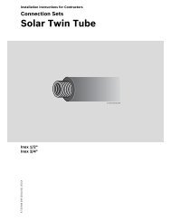
Hydraulic connection 88.1 Installing an air vent (accessory)Automatic air vents (accessory) simplify filling,commissioning, and servicing of solar thermal systems.In order for the air vent to work properly, it must beinstalled at the highest point of the system and all supplyand return piping should be sloped toward the collectors(Fig. 50).NOTICEWhen using corrugated stainless steelpiping for extended lengths of the supplyand return lines, an automatic air vent isrequired.Avoid frequent changes in direction.12NOTICEIf the system requires significant dips inthe pipework, it may be necessary to installadditional air vents in order to be able toremove all the air during commissioning.Fig. 50 Air vent installed on the supply connection1 Collector sensor2 Automatic air vent63043965.58-1.SDIf an automatic air vent can not be installed due to spacerestrictions, use a manual air vent valve.NOTICEOnly use air vents that are rated for thetemperatures and glycol fluids of solarsystems.12Description of the automatic air ventThe automatic air vent contains a float that opens a valveif air is collecting and releases the air to the outside. Thevalve closes once the air was released and liquid reachesthe float. The air vent must be positioned perfectlyvertically. Otherwise the float may not work properly.During stagnation steam is generated which wouldescape through the air vent. Therefore a ball valve isinstalled before the air vent which must be closed afterthe system is commissioned. Only during servicing maythe ball valve be opened.The air vent has a bleeder screw at its top protected bya weather cap (Fig. 51, [1]) In order to preventcontamination this weather cap must always beinstalled. To bleed air from the system open the ballvalve and unscrew the bleeder screw one full revolution.Close both after completing the operation.9 8 7 7Fig. 51 Automatic air vent SKN 3.0345663043965.59-1.SDAutomatic air vent kit SKN 3.0 (Fig. 51):1 Weather protection cap 1 ×2 Automatic air vent 1 ×3 Ball valve 1 ×4 Gasket 1 ×5 Vent body 1 ×6 Double nipple with O-ring 1 ×7 Hose fitting with O-ring 2 ×8 Hose clamp 2 ×9 Solar hose 2 in (55 mm) 1 ×Logasol SKN 3.0 - We reserve the right to make any changes due to technical modifications. 35
8Hydraulic connection8.1.1 Installing the air vent valve under the roof Push long solar hose (40 in (1000 mm) Fig. 52, [2])onto the supply connection on the collector array andfix in place using hose clamp. Feed solar hose together with the sensor cablethrough the penetration (Fig. 52, [1]) and through theroof insulation.12Perform the same procedure with the return connection. Firmly screw R¾ hose fitting with O-ring (Fig. 52, [5])and double nipple with O-ring (Fig. 52, [3]) into the airvent (Fig. 52, [4]). Push hose fitting onto the solar hose as far as it willgo and fix in place using hose clamp (Fig. 52, [6]).6543NOTICEFor the return connection, you must installthe hose fitting and hose pipe adapter(from the connection kit) into the longsolar hose. Connect header pipe to the hose pipe adapter(Fig. 52, [3]).8.1.2 Installing the air vent valve on the roof Push short solar hose (4 in (55 mm)), Fig. 53, [1])onto the supply connection on the collector array andfix in place using hose clamp. Firmly screw R¾ hose fittings with O-rings(Fig. 53, [3]) into the air vent (Fig. 53, [4]). Insert hose fittings (Fig. 53, [3]) into the solar hoses(Fig. 53, [1] and [5]) as far as they will go, and fix inplace using hose clamps (Fig. 53, [2]). Insert hose fittings with compression ring(Fig. 53, [6]) into the solar hose as far as it will go,and fix in place with hose clamp. Feed solar hose together with the sensor cablethrough the penetration (Fig. 53, [7]) and through theroof insulation. Connect header pipe to the hose pipe fitting (¾ in (18mm)) (Fig. 53, [6]).NOTICEFor the return connection, you must installthe hose pipe adapter (from theconnection kit) into the long solar hose.63043965.60-1.SDFig. 52 Installing the solar hose to the supply connection1 Penetration2 Solar hose 40 in (1000 mm)3 Double nipple with O-ring4 Air vent body5 Hose fitting with O-ring6 Hose clamp71Fig. 53 Connecting the air vent valve on roof1 Solar hose 4 in (55 mm)2 Hose clamp3 Hose fitting with O-ring4 Air vent body5 Solar hose 40 in (1000 mm)6 Hose pipe adapter ¾ in (18 mm) with compression ring7 Penetration23 4352636Logasol SKN 3.0 - We reserve the right to make any changes due to technical modifications.
Connecting Two Collector Arrays (accessory) 99 Connecting Two Collector Arrays (accessory)The collector array connection set (Fig. 54, [8]) isavailable as an accessory and allows connecting twocollector arrays in series that are located in close vicinityof each other.NOTICEInstall all connection parts to thecollectors on the ground.Scope of delivery (Fig. 54)Item 1: Elbow 2 ×Item 2: Hose clamp 2 ×Item 3: Dummy plug 2 ×Item 4: Solar hose 2 in (55 mm) 2 ×Item 5: Solar hose 40 in (1000 mm) 1 ×Item 6: Union nut G1 2 ×Item 7: Washer 2 ×Installing additional dummy plugsFig. 546 7543Schematic diagram and scope of delivery112963043965.51-1.SD98Use the dummy plugs to close up any collectorconnections not in use (Fig. 55, [1]).1 Place 2 in (55 mm) solar hoses (Fig. 55, [3]) togetherwith the preassembled dummy plugs onto the twofree connections. Once the hose clamps are sitting correctly, pull thelocking rings to secure the connection.234Installing the connection set Remove plastic caps (transport protection) from therelevant collector connections. Push union nut (Fig. 56, [1]) over the collectorconnections. Place the washer (Fig. 56, [2]) behind the bead onthe collector connection and press together. Press elbow with O-ring (Fig. 56, [3]) ontoconnection, align and bolt together with union nut. Measure distance between the elbow (dim. X) oncethe collectors are installed, and cut the solar hose(Fig. 56, [5]) to size accordingly. Attach solar hose to the elbows and secure usinghose clamps (Fig. 56, [4]).Fig. 55Installing the preassembled dummy plugs1 2 363043965.52-1.SD45XFig. 56Connection set between two collector rows63043965.53-1.SDLogasol SKN 3.0 - We reserve the right to make any changes due to technical modifications. 37
10Final activities10 Final activities10.1 Checking the installationNOTICECarry out the final insulating work onlyonce all necessary checks have beenperformed.Checks1.2.3.4.5.6.Solar hoses secured with hose clamps(locking ring pulled)?Screws on the collector clamp (single-sidedand double-sided) tightened?Horizontal rails connected to roof hooks andthreaded clip?Collector hanger installed and snapped inhorizontal rails?Sensor inserted as far as it will go andsecured with strain relief?Pressure test carried out and all connectionsleak-proof (see pump station instructions)?NOTICEEnsure the ball valve on the automatic airvent is closed after commissioning.10.2 Insulating the Pipes above the RoofInsulation of the pipework in internal or externalinstallations– For the insulation of external pipework, use only UVand high temperature resistant insulating materials.– For the insulation of internal pipework, use only hightemperature resistant insulating materials.– Use only material that is bird and rodent proof.– Verify all penetrations are weather proof anddiscourage critters from entering the building.38Logasol SKN 3.0 - We reserve the right to make any changes due to technical modifications.
Quick reference guide for tile roof and pressure filling 1111 Quick reference guide for tile roof and pressure fillingThese instructions are only intended as an overview ofthe work to be carried out. You MUST follow the detaileddescriptions for the work on the pages mentioned, andobserve all safety and user instructions.Fitting roof hooks and horizontal rails12, 144 69, 111. Turn lower part of roof hook upward. Determine p. 14locations for the roof hooks while observing thedistances given in (Chapter 5.1 "Rail and hookspacing", page 14).2. Determine settings of the roof hook. p. 163. Connect horizontal rails together using railp. 25connectors.4. Fasten horizontal rails to roof hook. p. 255. Align horizontal rails horizontally and laterally flush p. 26with each other.6. Install collector hangers. p. 26Fig. 573Roof mounting1, 263043965.62-1.SDPreparing to install the collectors7. Install solar hoses (4 in (95 mm)) on the right-handside of the second and all remaining collectors.8. Push preassembled dummy plugs onto thoseconnections that are not needed and secure usinghose clamps.p. 29p. 29813 7 17 1018Fastening the collectors9. Push single-sided collector clamp into horizontal rails. p. 3010. Place first collector onto horizontal rails and push onto p. 30collector clamp.11. Tighten single-sided collector clamps. p. 3112. Place double-sided collector clamp into horizontal rail p. 31and push onto first collector.13. Push second collector with pre-assembled solar p. 31hoses towards the first collector and secure usinghose clamps.14. Tighten screws on the double-sided collector clamp. p. 3215. Repeat the procedure for all other collectors. p. 3216. Fit single-sided collector clamps on outside. p. 3218Fig. 58Hydraulic connections7 863043965.39-1.SD7 17 18, 20Header connection17. Insert collector sensor as far as it will go intop. 33the sensor well on the collector with the supplyconnection and secure.18. Push long solar hoses onto supply and returnp. 34connections and secure with hose clamps.19. Insert hose pipe adapters into solar hoses and secure p. 34with hose clamps.20. Feed solar hose together with sensor cable through p. 34penetration and roof insulation.21. Perform installation checks. p. 3822. Insulate header pipes with UV and high temperature p. 38resistant material.Fig. 59863043965.64-1.SDInstalling the collector sensor and header pipes19Logasol SKN 3.0 - We reserve the right to make any changes due to technical modifications. 39
12CollectorS 4.0S 4.012 Spare parts40Logasol SKN 3.0 - We reserve the right to make any changes due to technical modifications.
Collector 12Item Part Number Description Weight20 7747021972 SKN 3.0-S Solar Flat Plate Collector Portrait (vertical) 93 1/230 7747021974 SKN 3.0-W Solar Flat Plate Collector Landscape (horizontal) 95 1/2Logasol SKN 3.0 - We reserve the right to make any changes due to technical modifications. 41
12On roof installation material42Logasol SKN 3.0 - We reserve the right to make any changes due to technical modifications.
On roof installation material 12Item Part Number Desciption in lb10 63045246 Single-sided collector clamp 0.220 63045239 Horizontal rail, Portrait collector 3.121 63045240 Horizontal rail, Landscape collector 5.530 63045243 Collector hanger 0.2240 63045241 Connector rail connector 0.2550 63045244 Double sided collector clamp 0.2660 63045233 Roof hooks adjustable kpl 0.66Available individual part:70 63045237 Threaded clip M8 0.0680 x Screw M8x25 m.Logasol SKN 3.0 - We reserve the right to make any changes due to technical modifications. 43
12On roof installation material44Logasol SKN 3.0 - We reserve the right to make any changes due to technical modifications.
On roof installation material 12Item Part Number Description WeightMounting kits for heavy snow and wind loads10 63045254 High load rail vertical 5.5Hanger bolt kit30 63020003 Hanger bolt kit 0.44consists of:40 (x) Screw 8x16 10,9 A2 *2 pieces50 63020008 Attachment block M8/M12 f 0.160 (x) Hex nut DIN439 M12 A2 *1 piece70 (x) Washer DIN125 13 A2 *1 piece80 63020009 Gasket 0.0290 63020010 Stud M12x180 0.3Mounting kits for Slate- andShingle roofs100 63017467 Mounting-Set for Roof hooks for slate roofs 0.88consists of:110 (x) Roof hooks for slate roofs *1 piece120 (x) Screw M8x25 *1 piece130 (x) Washer DIN125 8,4 V2A *1 piece140 (x) Hex nut DIN985 M8 A4 *1 piece150 (x) Wood screw 6x70 *1 pieceLogasol SKN 3.0 - We reserve the right to make any changes due to technical modifications. 45
12Connection Set SKN/FKC46Logasol SKN 3.0 - We reserve the right to make any changes due to technical modifications.
Connection Set SKN/FKC 12Item Part Number Description Weight10 63046151 Elbow G1x18 G3/4 kpl 0.4Available individual parts:90 87182237740 Compression ring 1/2" (16 mm) 0.05Set 5 pieces90 63045250 Compression ring 3/4" (18 mm)Set 5 pieces70 63045310 O-Ring 21x3,0 Shore70 0.01Set 5 pieces15 63046195 Fastening-parts kit connection SKN/FKC 0.1consists of:120 (x) Nut G1 D25x17Ms100 (x) Lock washer G1x21 slotted20 63045247 Hose clamp DN30 0.2Set 5 pieces30 x Solarhose 3/4x55Pos. 60 use and accordinglycut to length40 63045248 Dummy plug D21 0.1680 85336132 Solar hose 3/4"x1000 1.65110 63045249 Hose connector 18 G3/4xD21 kpl 0.2Available individual parts:50 63045301 O-Ring 25x3,0 Shore70 0.02Set 5 Pieces90 87182237740 Compression ring 1/2" (16 mm) 0.05Set 5 pieces90 63045250 Compression ring 3/4" (18 mm)Set 5 piecesAvailable individual parts:70 63045310 O-Ring 21x3,0 Shore70 0.01Set 5 pieces15 63045306 Fastening-parts kit Row SKN/FKC *consists of:120 (x) Nut G1 D25x17Ms100 (x) Lock washer G1xD21slottedLogasol SKN 3.0 - We reserve the right to make any changes due to technical modifications. 47
12Row connection set SKN/FKCSKN/FKC67910167-00-Row connection set SKN/FKCRow connection set SKN/SKS48Logasol SKN 3.0 - We reserve the right to make any changes due to technical modifications.
Row connection set SKN/FKC 12Item Part Number Description WeightRow connecting set SKN/FKC10 63045253 Elbow G1xD21 Ms kpl 2.5Available individual parts:20 63045310 O-Ring 21x3,0 Shore70 0.01Set 5 pieces80 63045306 Fastening-parts kit Row SKN/FKC *consists of:30 x Lock washer G1x21 slotted85 x Nut G1 D25x17Ms40 63045247 Hose clamp DN30 0.19Set 5 pieces50 85336132 Solar hose 3/4"x1000 1.6560 x Solarhose 3/4x55Pos. 50 use and accordinglycut to length70 63045248 Dummy plug D21 0.14Logasol SKN 3.0 - We reserve the right to make any changes due to technical modifications. 49
12Air vent set SKN/FKCAir vent below the roofAir vent abovethe roof67910064-00-Air Vent Set SKN/FKC50Logasol SKN 3.0 - We reserve the right to make any changes due to technical modifications.
Air vent set SKN/FKC 12Item Part Number Description Weight20 63045247 Hose clip DN30 0.19Set 5 pieces30 85336132 Solar hose 3/4"x1000 1.5440 63015362 Air Vent Valve autom R3/8 Solar 0.8650 85103282 Ball valve 3/8" 0.5560 63012692 Cover D17x24x2 AFM34 (5x) 0.0470 63045299 Air vent body 0.88Available individual parts:130 63045301 O-Ring 25x3,0 Shore70 0.02Set 5 pieces160 63020599 Compression ring DN16x1,5 0.033Set 10 pieces90 x Solar hose 3/4"x55see Pos. 30, Part accordinglycut to length100 87182237070 Hose fitting 18 G3/4xD21 kpl 0.02Available individual parts:130 63045301 O-Ring 25x3,0 Shore70 0.02Set 5 pieces110 63045249 Hose pipe adapter 18 G3/4xD21 kpl 0.2Available individual parts:130 63045301 O-Ring 25x3,0 Shore70 0.02Set 5 pieces140 87182237740 Compression ring 1/2" (16 mm) 0.05Set 5 pieces140 63045250 Compression ring 3/4" (18 mm)Set 5 pieces120 63045263 Connector SKN/FKC 18 G3/4 kpl 0.21Available individual parts:130 63045301 O-Ring 25x3,0 Shore70 0.02Set 5 pieces150 63045264 O-Ring 15x3 SHORE70 EPDM291 0.01Set 5 piecesLogasol SKN 3.0 - We reserve the right to make any changes due to technical modifications. 51
CertificationCertification52Logasol SKN 3.0 - We reserve the right to make any changes due to technical modifications.
NotesLogasol SKN 3.0 - We reserve the right to make any changes due to technical modifications. 53
Notes54Logasol SKN 3.0 - We reserve the right to make any changes due to technical modifications.
NotesLogasol SKN 3.0 - We reserve the right to make any changes due to technical modifications. 55