FTB-8115 Datasheet EN Version - 3 EDGE GmbH
FTB-8115 Datasheet EN Version - 3 EDGE GmbH
FTB-8115 Datasheet EN Version - 3 EDGE GmbH
- No tags were found...

You also want an ePaper? Increase the reach of your titles
YUMPU automatically turns print PDFs into web optimized ePapers that Google loves.
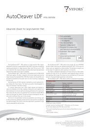
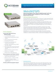
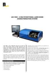
<strong>FTB</strong>-<strong>8115</strong>Transport BlazerNETWORK TESTING—TRANSPORT AND DATACOMSONET/SDH TEST MODULEFully integrated test solution supportingSONET/SDH test functionsPlatform Compatibility<strong>FTB</strong>-200 Compact Platform<strong>FTB</strong>-400 Universal Test SystemDS0/E0 to OC-48/STM-16 testing in a single moduleSupports SONET, SDH, DSn and PDHSmartMode automatic signal structure discovery with real-timealarm/error/pointer movement monitoringIntuitive, feature-rich user interface with available automated testscripting and multi-user remote management capabilitiesSupported on <strong>FTB</strong>-200 and <strong>FTB</strong>-400 platforms, optimizing capitalexpenditureswww.EXFO.comTelecom Test and Measurement
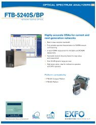
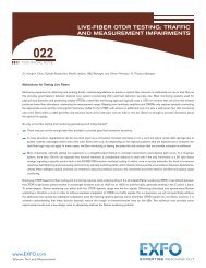
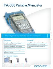
<strong>FTB</strong>-<strong>8115</strong>Transport Blazer SONET/SDH Test ModuleAdvanced SONET/SDHAccess and Metro TestingEXFO’s <strong>FTB</strong>-<strong>8115</strong> Transport Blazer test module combines advanced DSn/PDH and SONET/SDH test functions in a single unit,eliminating the need for multiple, purpose-built test platforms for the commissioning or troubleshooting of T1/E1 to OC-48/STM-16circuits. The extensive list of DSn, SONET, PDH and SDH features available on the <strong>FTB</strong>-<strong>8115</strong> Transport Blazer allows users to performa wide range of tests from simple bit-error-rate (BER) analysis to more advanced network characterization and troubleshooting.These functions include:Mixed and bulk payload generationand analysis from 64 Kbit/sto 2.5 Gbit/sHigh-order mappings:STS-1/3c/6c/9c/12c/24c/48c andAU-3/AU-4/AU-4-2c/3c/4c/8c/16cLow-order mappings: VT1.5/2/6,TU-11/12/2/3Section, line, high-order (HO) andlow-order (LO) path overheadmanipulation and monitoringSection, line, high-order and loworderpath alarm/error generationand monitoringHigh-order and low-order pointergeneration and monitoringPerformance monitoring: G.821,G.826, G.828, G.829, M.2100, M.2101Frequency analysis and powermeasurementFrequency offset generationAutomatic protection switching andservice disruption timemeasurementsRound-trip delay measurementsDual DS1/DS3 receiver testingIndependent transmitter andreceiver testingThrough mode analysisDS1 FDL and loopcodesFractional T1/E1 testingTandem connection monitoringSONET/SDHNESONET/SDHNESONET/SDHNESONET/SDHNEHoused in either the <strong>FTB</strong>-400 or <strong>FTB</strong>-200 platform, the <strong>FTB</strong>-<strong>8115</strong>module enables field circuit turn-up and troubleshooting.SMARTMODE: REAL-TIME SIGNAL STRUCTUREDISCOVERY AND MONITORINGEXFO’s <strong>FTB</strong>-<strong>8115</strong> Transport Blazer supports a unique feature called SmartMode.This provides users with full visibility of all high-order (STS/AU) and low-order(VT/TU) mixed mappings within the incoming SONET/SDH test signal.SmartMode automatically discovers the signal structure of the OC-n/STM-n line,including mixed mappings. In addition to this in-depth multichannel visibility,SmartMode performs real-time monitoring of all discovered high-order paths anduser selected low-order paths simultaneously, providing users with the industry’smost powerful SONET/SDH multichannel monitoring and troubleshooting solution.Real-time monitoring allows users to easily isolate network faults, saving valuabletime and minimizing service disruption. SmartMode also provides one-touch testcase start, allowing users to quickly configure a desired test path.<strong>FTB</strong>-<strong>8115</strong> SmartMode: multichannel signal discovery with real-timealarm scan (shown in the <strong>FTB</strong>-400 user interface).www.EXFO.com
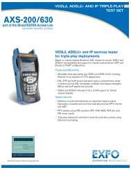
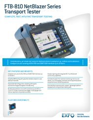
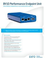
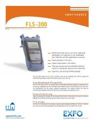
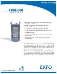
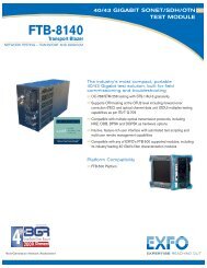
<strong>FTB</strong>-<strong>8115</strong>Transport Blazer SONET/SDH Test ModuleUnsurpassed Configurationand Operational FlexibilityMULTIPLATFORM SUPPORT AND VERSATILITYThe <strong>FTB</strong>-<strong>8115</strong> Transport Blazer module is supported and interchangeable on boththe <strong>FTB</strong>-400 Universal Test System and the <strong>FTB</strong>-200 Compact Platform.This cross-platform support provides users with added flexibility by enabling themto select the appropriate platform that suits their testing needs. EXFO is the first andonly test solution provider to offer this versatility, delivering single to multi-applicationtest solutions with the same hardware module, which in turn dramatically reducescapital expenditures.Inserted in the <strong>FTB</strong>-200 Compact Platform, the <strong>FTB</strong>-<strong>8115</strong> Transport Blazer moduledelivers SONET/SDH test functions in a small, lightweight platform, ideal for fieldtechnicians’ installation and commissioning needs. When combined with the<strong>FTB</strong>-200’s optional integrated high-precision power meter, visual fault locator andfiber scope, this solution provides all the critical test tools required for day-to-dayactivities, eliminating the need to carry and manage multiple test sets.With its modular, multislot design, the <strong>FTB</strong>-400 platform enablesusers to configure and upgrade their systems in the field accordingto their testing needs, minimizing capital expenditures.The <strong>FTB</strong>-<strong>8115</strong> module is supported on both the <strong>FTB</strong>-200 andthe <strong>FTB</strong>-400 platforms.The <strong>FTB</strong>-400 platform configuration—used with either the four-slot (GP-404) oreight-slot (GP-408) receptacle—provides users with an all-in-one solutionsupporting a mix of Transport Blazer modules, Packet Blazer modules(<strong>FTB</strong>-8510G 10 Gigabit Ethernet, <strong>FTB</strong>-8510 Ethernet, <strong>FTB</strong>-8520 SAN) andoptical-layer test modules, making it the industry’s first truly integrated networktesting platform. The resulting modularity enables users to upgrade their systemsin the field according to their testing needs. This multiservice test platform is theideal solution for field, central office and lab applications.HARDWARE UPGRADABILITYPart of the Transport Blazer family of products, the <strong>FTB</strong>-<strong>8115</strong> module can befactory upgraded to support 10 Gbit/s operation. In addition, the upgrades caninclude Next-Generation Ethernet-over-SONET/SDH test functions, such asgeneric framing procedure (GFP), virtual concatenation (VCAT) and link capacityadjustment scheme (LCAS).AUTOMATED TEST SCRIPTINGWhen configured for the <strong>FTB</strong>-400 platform, the<strong>FTB</strong>-<strong>8115</strong> Transport Blazer comes with a built-inmacrorecorder, allowing users to easily record theirtest actions and automatically create test scripts. Thisalso allows them to build standard test routines thatcan be easily accessed and run by field technicianswith little or no manual intervention.REMOTE MANAGEM<strong>EN</strong>TThe <strong>FTB</strong>-<strong>8115</strong> Transport Blazer module allows users to perform remote testingand data analysis, as well as remote monitoring via standard Ethernet or remotedial-up connections.TEST LOGGER AND REPORTINGEXFO’s <strong>FTB</strong>-<strong>8115</strong> Transport Blazer module supports a detailed test loggerand test reporting tools, enabling users to view any errors/alarms that occurredduring the test interval, which can then be used for post-processing of results or SLAconformance validation.Test logger: a detailed, time-stamped list of all events occurringduring test execution.www.EXFO.com
<strong>FTB</strong>-<strong>8115</strong>Transport Blazer SONET/SDH Test ModuleElectrical InterfacesThe following section provides detailed information on all supported electrical interfaces.DS1 E1/2M E2/8M E3/34M DS3/45M STS-1e/STM-0e/52M E4/140M STS-3e/STM-1e/155MTx Pulse Amplitude 2.4 to 3.6 V 3.0 V 2.37 V 2.37 V 1.0 ± 0.1 V 0.36 to 0.85 V 1.0 ± 0.1 Vpp 0.5 VTx Pulse Mask GR-499 G.703 G.703 G.703 G.703 DS-3 45MSTS-3eGR-499 G.703GR-253 G.703GR-253Figure 9.5 Figure 15 Figure 15 Figure 16 Figure 17 Figure 9-8 Figure 14 Figure 4-10/4-11 Figure 18/19Figure 4-12,4-13, 4-14Tx LBO PreamplificationPower dBdsx+0.6 dBdsx (0-133 ft) 0 to 225 ft 0 to 225 ft+1.2 dBdsx (133-266 ft) 225 to 450 ft 225 to 450 ft 0 to 225 ft+1.8 dBdsx (266-399 ft)+2.4 dBdsx (399-533 ft)+3.0 dBdsx (533-655 ft)STM-1e/155MG.703Figure 4-14/22, 23Cable SimulationPower dBdsx–22.5 dBdsx 450 to 900 (927) ft 450 to 900 (927) ft–15.0 dBdsx–7.5 dBdsx0 dBdsxRx Level Sensitivity For 772 kHz: For 1024 kHz: For 1024 kHz: For 4224 kHz: For 17.184 MHz: For 22.368 MHz: For 25.92 MHz: For 70 MHz: For 78 MHz:TERM: ≤ 26 dB (cable TERM: ≤ 6 dB TERM: ≤ 6 dB TERM: ≤ 6 dB TERM: ≤ 12 dB TERM: ≤ 10 dB TERM: ≤ 10 dB TERM: ≤ 12 dB TERM: ≤ 12.7 dBloss only) at 0 dBdsx Tx (cable loss only) (cable loss only) (cable loss only) (coaxial cable loss only) (cable loss only) (cable loss only) (coaxial cable loss only) (coaxial cable loss only)DSX-MON: ≤ 26 dB MON: ≤ 25 dB MON: ≤ 26 dB MON: ≤ 26 dB MON: ≤ 26 dB DSX-MON: ≤ 26.5 dB MON: ≤ 25 dB MON: ≤ 26 dB MON: ≤ 26 dB(20 dB resistive loss + (20 dB resistive loss (20 dB resistive loss + (20 dB resistive loss + (20 dB resistive loss + (21.5 dB resistive loss (20 dB resistive loss (20 dB resistive loss (20 dB resistive losscable loss ≤ 6 dB) + cable loss ≤ 6 dB) cable loss ≤ 6 dB) cable loss ≤ 6 dB) cable loss ≤ 6 dB) + cable loss ≤ 5 dB) + cable loss ≤ 5 dB) + cable loss ≤ 6 dB) + cable loss ≤ 6 dB)Bridge: ≤ 6 dB Bridge: ≤ 6 dB Bridge: ≤ 6 dB(cable loss only) (cable loss only) (cable loss only)Note: measurement units = dBdsx Note: measurement units = dBm Note: measurement units = dBm Note: measurement units = dBm Note: measurement units = dBm Note: measurement units = dBm Note: measurement units = dBm Note: measurement units = dBm Note: measurement units = dBmTransmit Bit Rate 1.544 Mbit/s ± 4.6 ppm 2.048 Mbit/s ± 4.6 ppm 2.048 Mbit/s ± 4.6 ppm 8.448 Mbit/s ± 4.6 ppm 34.368 Mbit/s ± 4.6 ppm 44.736 Mbit/s ± 4.6 ppm 51.84 Mbit/s ± 4.6 ppm 139.264 Mbit/s ±4.6 ppm 155.52 Mbit/s ± 4.6 ppmReceive Bit Rate 1.544 Mbit/s ± 140 ppm 2.048 Mbit/s ± 100ppm 2.048 Mbit/s ± 100ppm 8.448 Mbit/s ± 100 ppm 34.368 Mbit/s ± 100 ppm 44.736 Mbit/s ± 100 ppm 51.84 Mbit/s ± 100 ppm 139.264 Mbit/s ± 100 ppm 155.52 Mbit/s ± 100 ppmMeasurement Accuracy Frequency ± 4.6 ppm ±4.6 ppm ±4.6 ppm ± 4.6 ppm ± 4.6 ppm ±4.6 ppm ±4.6 ppm ±4.6 ppm ±4.6 ppmElectrical Power DSX range: ± 1.0 dB NORMAL: ± 1.0 dB NORMAL: ± 1.0 dB NORMAL: ± 1.0 dB NORMAL: ±1.0 dB DSX range: ± 1.0 dB DSX range: ± 1.0 dB NORMAL: ±1.0 dB NORMAL: ± 1.0 dBDSX-MON range: ± 2.0 dB MONITOR: ± 2.0 dB MONITOR: ± 2.0 dB MONITOR: ± 2.0 dB MONITOR: ±2.0 dB DSX-MON range: ±2.0 dB DSX-MON range: ±2.0 dB MONITOR: ±2.0 dB MONITOR: ±2.0 dBPeak-to-Peak Voltage ±10 % down to 500 mVpp ±10% down to 500 mVpp ±10% down to 500 mVpp ±10% down to 400 mVpp ±10% down to 200 mVpp ±10% down to 200 mVpp ±10% down to 200 mVpp ±10% down to 200 mVpp ±10% down to 200 mVppFrequency Offset Generation 1.544 Mbit/s ± 140 ppm 2.048 Mbit/s ± 70 ppm 2.048 Mbit/s ± 70 ppm 8.448 Mbit/s ± 50 ppm 34.368 Mbit/s ± 50 ppm 44.736 Mbit/s ± 50 ppm 51.84 Mbit/s ± 50 ppm 139.264 Mbit/s ± 50 ppm 155.52 Mbit/s ± 50 ppmIntrinsic Jitter (Tx) ANSI T1.403 section 6.3 G.823 section 5.1 G.823 section 5.1 G.823 section 5.1 G.823 section 5.1 GR-449 section 7.3 GR-253 section G.823 section 5.1 G.825 section 5.1GR-499 section 7.3 G.751 section 2.3 (categories I and II) 5.6.2.2 (category II) GR-253 section 5.6.2.2Input Jitter Tolerance AT&T PUB 62411 G.823 section 7.1 G.823 section 7.1 G.823 section 7.1 G.823 section 7.1 GR-449 section 7.3 GR-253 section 5.6.2.2 G.823 section 7.1 G.825 section 5.2GR-499 section 7.3 (categories I and II) (category II) G.751 section 3.3 GR-253 section 5.6.2.3Line Coding AMI and B8ZS AMI and HDB3 AMI and HDB3 HDB3 HDB3 B3ZS B3ZS CMI CMIInput Impedance 100 ohms ± 5%, balanced 120 ohms ± 5%, balanced 75 ohms ± 5%, unbalanced 75 ohms ± 5%, unbalanced 75 ohms ± 5%, unbalanced 75 ohms ±5%, unbalanced 75 ohms ±5%, unbalanced 75 ohms ± 10%, unbalanced 75 ohms ± 5%, unbalanced(Resistive Termination)Connector Type BANTAM and RJ-48C BANTAM and RJ-48C BNC BNC BNC BNC BNC BNC BNCSPECIFICATIONS Synchronization InterfacesaExternal Clock DS1/1.5M <strong>FTB</strong>-85102 External Clock E1/2M <strong>FTB</strong>-8510-12 External Clock E1/2M <strong>FTB</strong>-8510-22 MHzTx Pulse Ports Amplitude Gigabit Ethernet 2.4 to 3.6 V Two 10/100Base-T 3.0 V Two 10/100Base-T 2.37 V Two 10/100Base-T and 0.75 two to 1.5 VTx Pulse Mask GR-499 figure 9.5 G.703 figure 15 and one Gigabit EthernetG.703 figure 15 G.703 figure 20Connector types Typical power dBdsx RJ-45 (ISO 8877) RJ-45 (ISO 8877) and LC RJ-45 (ISO 8877) and LCConnect speed (Mb/s) +0.6 dBdsx (0-133 ft) 10/100 10/100/1000 10/100/1000Tx LBO Duplex mode +1.2 dBdsx (133-266 ft) Full/half-duplex Full/half-duplex Full/half-duplexPreamplification+1.8 dBdsx (266-399 ft) auto-negotiation auto-negotiation auto-negotiationMaximum port capacity (Mb/s) +2.4 dBdsx (399-533 ft) 200 (bidirectional) 2000 (bidirectional) 2000 (bidirectional)Ethernet testing +3.0 dBdsx (533-655 ft) RFC 2544 RFC 2544 RFC 2544Rx Level TERM: ≤ 6 dB (cable loss RFC only) 1242 (at 772 KHz for T1) TERM: = ≤ 6 dB RFC (cable loss 1242 only) TERM: = ≤ 6 dB (cable loss RFC only) 1242Sensivity DSX-MON: ≤ 26 dB (20 dB resistive loss + cable loss ≤ 6 dB) MON: ≤ 26 dB (20 dB resistive loss + cable loss ≤ 6 dB) MON: ≤ 26 dB (resistive loss + cable loss ≤ 6 dB) ≤ 6 dB (cable loss only)Bridge: ≤ 6 dB (cable loss only) Bridge: ≤ 6 dB (cable loss only) Bridge: ≤ 6 dB (cable loss only)Transmission Bit Rate 1.544 Mbit/s ± 4.6 ppm 2.048 Mbit/s ± 4.6 ppm 2.048 Mbit/s ± 4.6 ppmReception Bit Rate 1.544 Mbit/s ± 140 ppm 2.048 Mbit/s ± 100 ppm 2.048 Mbit/s ± 100 ppmIntrinsic Jitter (Tx)ANSI T1.403 section 6.3 G.823 G.823 G.703GR-499 section 7.3 section 6.1 section 6.1 table 11Input Jitter AT&T PUB 62411 G.823 section 7.2 G.823 section 7.2Tolerance GR-499 SECTION 7.3 G.813 G.813Line Coding AMI and B8ZS AMI and HDB3 AMI and HDB3Input Impedance 75 ohms ± 5%, 75 ohms ± 5%, 75 ohms ± 5%, 75 ohms ± 5%,(Resistive Termination) unbalanced unbalanced unbalanced unbalancedConnector Type BNC a BNC a BNC BNCNOTEa. Adaptation cable required for BANTAM.www.EXFO.com
<strong>FTB</strong>-<strong>8115</strong>Transport Blazer SONET/SDH Test ModuleOptical InterfacesThe following section provides detailed information on all supported optical interfaces.OC-3/STM-1o OC-12/STM-4o OC-48/STM-16o15 km; 1310 nm 40 km; 1310 nm 80 km; 1550 nm 15 km; 1310 nm 40 km; 1310 nm 80 km; 1550 nm 15 km; 1310 nm 40 km; 1310 nm 40 km; 1550 nm 80 km; 1550 nmTx Level —15 to —8 dBm —5 to 0 dBm —5 to 0 dBm —15 to —8 dBm —3 to +2 dBm —3 to +2 dBm –5 to 0 dBm –2 to +3 dBm –5 to 0 dBm –2 to +3 dBmRx Level Sensitivity —28 to —8 dBm —34 to —10 dBm —34 to —10 dBm —28 to —8 dBm —28 to —8 dBm —28 to —8 dBm –18 to 0 dBm –27 to –9 dBm –18 to 0 dBm –28 to –9 dBmTransmission Bit Rate 155.52 Mbit/s ± 4.6 ppm 155.52 Mbit/s ± 4.6 ppm 155.52 Mbit/s ± 4.6 ppm 622.08 Mbit/s ± 4.6 ppm 622.08 Mbit/s ± 4.6 ppm 622.08 Mbit/s ± 4.6 ppm 2.48832 Gbit/s ± 4.6 ppmReception Bit Rate 155.52 Mbit/s ± 100 ppm 155.52 Mbit/s ± 100 ppm 155.52 Mbit/s ± 100 ppm 622.08 Mbit/s ± 100 ppm 622.08 Mbit/s ± 100 ppm 622.08 Mbit/s ± 100 ppm 2.48832 Gbit/s ± 100 ppmOperational 1261 to 1360 nm 1263 to 1360 nm 1480 to 1580 nm 1274 to 1356 nm 1280 to 1335 nm 1480 to 1580 nm 1260 to1360 nm 1280 to1335 nm 1430 to1580 nm 1500 to1580 nmWavelength RangeSpectral Width 7.7 nm RMS 1 nm (20 dB from center) 1 nm (20 dB from center) 4 nm RMS 1 nm (20 dB from center) < 1 nm (20 dB from center) < 1 nm (–20 dB from center)Frequency Offset Generation 155.52 Mbit/s ± 50 ppm 155.52 Mbit/s ± 50 ppm 155.52 Mbit/s ± 50 ppm 622.08 Mbit/s ± 50 ppm 622.08 Mbit/s ± 50 ppm 622.08 Mbit/s ± 50 ppm 2.48832 Gbit/s ± 50 ppmMeasurement Accuracy Frequency ±4.6 ppm ±4.6 ppm ±4.6 ppm ±4.6 ppm ±4.6 ppm ±4.6 ppm ±4.6 ppmOptical Power ±2 dB ±2 dB ±2 dB ±2 dB ±2 dB ±2 dB ±2 dBMaximum Rx before +3 dBm +3 dBm +3 dBm +3 dBm +3 dBm +3 dBm +3 dBmDamage aJitter Compliance GR-253 (SONET) GR-253 (SONET) GR-253 (SONET) GR-253 (SONET) GR-253 (SONET) GR-253 (SONET) GR-253 (SONET)G.958 (SDH) G.958 (SDH) G.958 (SDH) G.958 (SDH) G.958 (SDH) G.958 (SDH) G.958 (SDH)Line Coding NRZ NRZ NRZ NRZ NRZ NRZ NRZEye Safety Class 1 laser complies Class 1 laser complies Class 1 laser complies Class 1 laser complies Class 1 laser complies Class 1 laser complies Class 1 laser complieswith 21 CFR 1040.10 with 21 CFR 1040.10 with 21 CFR 1040.10 with 21 CFR 1040.10 with 21 CFR 1040.10 with 21 CFR 1040.10 with 21 CFR 1040.10and 1040.11 and 1040.11 and 1040.11 and 1040.11 and 1040.11 and 1040.11 and 1040.11Connector Dual LC Dual LC Dual LC Dual LC Dual LC Dual LC Dual LCTranceiver Type b SFP SFP SFP SFP SFP SFP SFPNOTESa. In order not to exceed the maximum receiver power level before damage, an attenuator must be used.b. SFP compliance: The <strong>FTB</strong>-<strong>8115</strong> selected SFP shall meet the requirements stated in the “Small Form-Factor Pluggable (SFP) Transceiver Multisource Agreement (MSA)”.The <strong>FTB</strong>-<strong>8115</strong> selected SFP shall meet the requirements stated in the “Specification for Diagnostic Monitoring Interface for Optical Xcvrs”.www.EXFO.com
<strong>FTB</strong>-<strong>8115</strong>Transport Blazer SONET/SDH Test ModuleFUNCTIONAL SPECIFICATIONSSONET and DSnNOTESa. 1.5M (DS1) and 45M (DS3) interfaces discribed under SONET and DSn column.b. Not supported for E4 (140M).www.EXFO.comSDH and PDHOptical interfaces OC-3, OC-12, OC-48 Optical interfaces STM-1, STM-4, STM-16Available wavelengths (nm) 1310, 1550 Available wavelengths (nm) 1310, 1550Electrical interfaces DS1, DS3, STS-1e, STS-3e Electrical interfaces a 1.5M (DS1), 2M (E1), 8M (E2), 34M (E3), 45M (DS3), 140M (E4),STM-0e, STM-1eDS1 framing Unframed, SF, ESF 2M framing Unframed, PCM30, PCM31, PCM30 CRC-4, PCM31 CRC-4DS3 framing Unframed, M13, C-bit parity 8M, 34M, 140M framing Unframed, framedClocking Internal, loop-timed, external (BITS), inter-module Clocking Internal, loop-timed, external (MTS/SETS), 2 MHz, inter-moduleMappingsMappingsVT1.5 Bulk, DS1 TU-11-AU-3, TU-11-AU-4 Bulk, 1.5MVT2 Bulk, E1 TU-12-AU-3, TU-12-AU-4 Bulk, 2MVT6 Bulk TU-3-AU-4 Bulk, 34M, 45MSTS-1 SPE Bulk, DS3 TU-2-AU-3, TU-2-AU-4 BulkSTS-3c/6c/9c/12c/24c/48c, SPE Bulk AU-4 Bulk, 140MAU-4-2c/3c/4c/8c/16c BulkSONET overhead analysis A1, A2, J0, E1, F1, D1-D12, K1, K2, S1, M0, E2, J1, SDH overhead analysis A1, A2, J0, E1, F1, D1-D12, K1, K2, S1, M0, E2, J1, C2,and manipulation C2, G1, F2, H4, Z3, Z4, Z5, N1, N2 and manipulation G1, F2, F3, K3, N1, N2Error insertionError insertionDS1 Framing bit, BPV, CRC-6, bit error E1 (2M) Bit error, FAS, CV, CRC-4, E-bitDS3 BPV, C-bit, F-bit, P-bit, FEBE, bit error E2 (8M), E3 (34M), E4 (140M) Bit error, FAS, CVSTS-1e, STS-3e Section BIP (B1), line BIP (B2), path BIP (B3), STM-0e, STM-1e RS-BIP (B1), MS-BIP (B2), HP-BIP (B3), MS-REI, HP-REI,BIP-2, REI-L, REI-P, REI-V, BPV, bit errorLP-BIP-2, LP-REI, bit error, CVOC-3, OC-12, OC-48 Section BIP (B1), line BIP (B2), path BIP (B3), STM-1, STM-4, STM-16 RS-BIP (B1), MS-BIP (B2), HP-BIP (B3), MS-REI,BIP-2, REI-L, REI-P, REI-V, bit errorHP-REI, LP-BIP-2, LP-REI, bit errorError measurementError measurementDS1 Framing bit, BPV, CRC-6, excess zeros, bit error E1 (2M) Bit error, FAS, CV, CRC-4, E-bitDS3 BPV, C-bit, F-bit, P-bit, FEBE, bit error E2 (8M), E3 (34M), E4 (140M) Bit error, FAS, CVSTS-1e, STS-3e Section BIP (B1), line BIP (B2), path BIP (B3), STM-0e, STM-1e RS-BIP (B1), MS-BIP (B2), HP-BIP (B3), MS-REI, HP-REI,BIP-2, REI-L, REI-P, REI-V, BPV, bit errorLP-BIP-2, LP-REI, bit error, CVOC-3, OC-12, OC-48 Section BIP (B1), line BIP (B2), path BIP (B3), STM-1, STM-4, STM-16 RS-BIP (B1), MS-BIP (B2), HP-BIP (B3), MS-REI,BIP-2, REI-L, REI-P, REI-V, bit errorHP-REI, LP-BIP-2, LP-REI, bit errorAlarm insertionAlarm insertionDS1 LOS, RAI, AIS, OOF, pattern loss E1 (2M) LOS, LOS Mframe, LOS CRC Mframe, LOF, AIS, TS16 AIS,RAI, RAI Mframe, pattern lossDS3 LOS, RDI, AIS, OOF, DS3 idle, pattern loss E2 (8M), E3 (34M), E4 (140M) LOS, LOF, RAI, AIS, pattern lossSTS-1e, STS-3e, LOS, LOF, SEF, AIS-L, RDI-L, AIS-P, LOP-P, LOM, PDI-P, STM-0e, STM-1e, LOS, LOF, OOF, MS-AIS, MS-RDI, AU-AIS, AU-LOP,OC-3, OC-12, OC-48 RDI-P, ERDI-PCD, ERDI-PPD, ERDI-PSD, UNEQ-P, STM-1, STM-4, STM-16 H4-LOM, HP-PDI, ERDI-PSD, ERDI-PCD, ERDI-PPD,AIS-V, LOP-V, RDI-V, ERDI-VCD, ERDI-VPD, ERDI-VSD,HP-UNEQ, TU-AIS, LP-RFI, LP-RDI, ERDI-VCD, ERDI-VPD,RFI-V, UNEQ-V, pattern lossERDI-VSD, LP-RFI, LP-UNEQ, pattern lossAlarm detectionAlarm detectionDS1 LOS, loss of clock (LOC), RAI, AIS, OOF, pattern loss E1 (2M) LOS, LOS Mframe, LOS CRC Mframe, LOC, LOF, AIS,TS16 AIS, RAI, RAI Mframe, pattern lossDS3 LOS, LOC, RDI, AIS, OOF, DS3 idle, pattern loss E2 (8M), E3 (34M), E4 (140M) LOS, LOC, LOF, RAI, AIS, pattern lossSTS-1e, STS-3e, LOS, LOC, LOF, SEF, TIM-S, AIS-L, RDI-L, AIS-P, LOP-P, LOM, PDI-P, STM-0e, STM-1e, LOS, LOF, LOC, OOF, RS-TIM, MS-AIS, MS-RDI, AU-AIS, AU-LOP,OC-3, OC-12, OC-48 RDI-P, ERDI-PCD, ERDI-PPD, ERDI-PSD, PLM/SLM-P, STM-1, STM-4, STM-16 H4-LOM, HP-RDI, ERDI-PSD, ERDI-PCD, ERDI-PPD, HP-PLM/SLM,UNEQ-P, TIM-P, AIS-V, LOP-V, RDI-V, ERDI-VCD, ERDI-VPD,HP-UNEQ, HP-TIM, TU-AIS, LP-RFI, LP-RDI, ERDI-VCD, ERDI-VPD,ERDI-VSD, RFI-V, UNEQ-V, TIM-V, PLM/SLM-V, pattern lossERDI-VSD, LP-RFI, LP-UNEQ, LP-TIM, LP-PLM/SLM, pattern lossFrequency alarm on all supported interfaces.PatternsPatternsDS0 2E9-1, 2E11-1, 2E20-1, User defined E0 (64K) 2E9-1, 2E11-1, 2E20-1, User definedDS1 2E9-1, 2E11-1, 2E15-1, 2E20-1, 2E23-1, 2E31-1, 1100, E1 (2M) 2E9-1, 2E11-1, 2E15-1, 2E20-1, 2E23-1, 2E31-1, 1100,1010, 1111, 0000, QRSS, 1-in-8, 1-in-16, 3-in-24, 32 bit 1010, 1111, 0000, 1-in-8, 1-in-16, 3-in-24, 32 bitprogrammable (inverted or non-inverted), T1-DALY,programmable (inverted or non-inverted), bit errors55-OCTET bit errorsDS3 2E9-1, 2E11-1, 2E15-1, 2E20-1, 2E23-1, 2E31-1, 1100, E2 (8M), E3 (34M), E4 (140M) 2E9-1, 2E11-1, 2E15-1, 2E20-1, 2E23-1, 2E31-1, 1100,1010, 1111, 0000, QRSS, 1-in-8, 1-in-16, 3-in-24, 1010, 1111, 0000, 1-in-8, 1-in-16, 3-in-24 b ,32 bit programmable (inverted or non-inverted), bit errors 32 bit programmable (inverted or non-inverted), bit errorsVT1.5/2/6 2E9-1, 2E11-1, 2E15-1, 2E20-1, 2E23-1, 2E31-1, TU-11/12/2/3 2E9-1, 2E11-1, 2E15-1, 2E20-1, 2E23-1, 2E31-1, 1100,1100, 1010, 1111, 0000, QRSS, 1-in-8, 1-in-16, 1010, 1111, 0000, 1-in-8, 1-in-16,32 bit programmable (inverted or non-inverted), bit errors 32 bit programmable (inverted or non-inverted), bit errorsSTS-1, STS-3c/6c/9c/ 2E9-1, 2E11-1, 2E15-1, 2E20-1, 2E23-1, 2E31-1, 1100, AU-3/AU-4/AU4-2c/3c/4c/8c/16c 2E9-1, 2E11-1, 2E15-1, 2E20-1, 2E23-1, 2E31-1, 1100,12c/24c/48c, SPE 1010, 1111, 0000, 1-in-8, 1-in-16, 32 bit 1010, 1111, 0000, 1-in-8, 1-in-16, 32 bitprogrammable (inverted or non-inverted), bit errorsprogrammable (inverted or non-inverted), bit errorsLSS (loss of pattern) and bit error generation and analysis supported on all patterns.
<strong>FTB</strong>-<strong>8115</strong>Transport Blazer SONET/SDH Test ModuleADDITIONAL TEST AND MEASUREM<strong>EN</strong>T FUNCTIONSPower measurementsFrequency measurementsFrequency offset generationDual DSn receiversSupports power measurements, displayed in dBm (dBdsx for DS1), for optical and electrical interfaces.Supports clock frequency measurements (i.e., received frequency and deviation of the input signal clock from nominal frequency), displayed inppm and b/s (bps), for optical and electrical interfaces.Supports offsetting the clock of the transmitted signal on a selected interface to exercise clock recovery circuitry on network elements.Supports two DS1 or DS3 receivers, allowing users to simultaneously monitor two directions of a circuit under test in parallel, resulting in quickisolation of the source of errors.Performance monitoringThe following ITU-T recommendations, and corresponding performance monitoring parameters, are supported on the <strong>FTB</strong>-<strong>8115</strong>.ITU-T recommendationPerformance monitoring statisticsG.821 ES, EFS, EC, SES, UAS, ESR, SESR, DMG.826 ES, EFS, EB, SES, BBE, UAS, ERS, SESR, BBERG.828 ES, EFS, EB, SES, BBE, SEP, UAS, ESR, SESR, BBER, SEPIG.829 ES, EFS, EB, SES, BBE, UAS, ESR, SESR, BBERM.2100 ES, SES, UAS, ESR, SESRM.2101 ES, SES, BBE, UAS, ESR, SESR, BBERPointer adjustment and analysisGeneration and analysis of HO/AU and LO/TU pointer adjustments as per GR-253, and ITU-T G.703GenerationAnalysis• Pointer increment and decrement • Pointer increments• Pointer jump with or without NDF • Pointer decrements• Pointer value• Pointer jumps (NDF, no NDF)• Pointer value and cumulative offsetService disruption time measurements The service disruption time test tool measures the time during which there is a disruption of service due to the network switching from the activechannels to the backup channels.User-selectable triggers: All supported alarms and errors.Measurements: last disruption, shortest disruption, longest disruption, average disruption, total disruption, and service disruption count.Round-trip delay measurements The round-trip delay test tool measures the time required for a bit to travel from the <strong>FTB</strong>-<strong>8115</strong> transmitter back to its receiver after crossing a farendloopback. Measurements are supported on all supported <strong>FTB</strong>-<strong>8115</strong> interfaces and mappings.Measurements: last RTD time, minimum, maximum, average, measurement count (no. of successful RTD tests), failed measurement count.APS message control and monitoring Ability to monitor and set up automatic protection switching messages (K1/K2 byte of SONET/SDH overhead).Synchronization statusAbility to monitor and set up synchronization status messages (S1 byte of SONET/SDH overhead).Signal label control and monitoring Ability to monitor and set up payload signal labels (C2, V5 bytes of SONET/SDH overhead).Through modeAbility to perform Through mode analysis of any incoming electrical (DSn, PDH) and optical line (OC-3/12/48, STM-1/4/16).M13 mux/demuxAbility to multiplex/demultiplex a DS1 signal into/from a DS3 signal. (Note: E1 to DS3 mux/demux available with G.747 software option.)DS1 FDLSupport for DS1 Facility Data Link testing.DS1 loopcodesSupport for generation of DS1 in-band loopcodes.Tandem connection monitoring (TCM) a Tandem connection monitoring (TCM), option 2 b , is used to monitor the performance of a subsection of a SONET/SDH path routed via differentnetwork providers. The <strong>FTB</strong>-<strong>8115</strong> supports transmitting and receiving alarms and errors on a TCM link; also, transmission and monitoring of thetandem connection (TC) trace can be generated to verify the connection between TCM equipment.Error generation: TC-IEC, TC-BIP, TC-REI, OEIError analysis: TC-IEC, TC-REI, OEI, TC-VIOLAlarm generation: TC-RDI, TC-UNEQ, ODI, TC-LTC, TC-IAISAlarm analysis: TC-TIM, TC-RDI, TC-UNEQ, ODI, TC-LTC, TC-IAISADDITIONAL FEATURESScriptingReportsPower-up and restoreStore and load configurationsAlarm hierarchyConfigurable test viewsConfigurable test timerRemote controlThe built-in scripting engine and embedded macro-recorder provide a simple means of automating test cases and routines. Embedded scriptingroutines provide a powerful means of creating advanced test scripts. Available for the <strong>FTB</strong>-400 platform.Supports generation of test reports in .html, .csv, .txt, .pdf formats. Contents or reports are customizable by the user.In the event of a power failure to the unit, the active test configuration and test logger are saved and restored upon bootup.Ability to store and load test configurations to/from non-volatile memory.Alarms are displayed according to a hierarchy based on root cause. Secondary effects are not displayed. This hierarchy serves to facilitate alarmanalysis.This allows users to customize their test views, i.e., to dynamically insert or remove test tabs/windows, in addition to creating new test windows,so as to accurately match their testing needs.Provides the ability for a user to set pre-defined test start and stop times.Remote management software. This allows users to remotely monitor and control the <strong>FTB</strong>-<strong>8115</strong> module via standard Ethernet connection.NOTESa. HOP and LOP supported.b. G.707 option 2.www.EXFO.com
SPECIFICATIONS<strong>FTB</strong>-<strong>8115</strong>SONET/SDH 155 Mbit/s, 622 Mbit/s and 2.5 Gbit/sAnalyzer module supporting up to OC-48/STM-16 opticalrates, as well as electrical DSn/PDH interfacesTest InterfacesSONET: STS-1e, STS-3e, OC-3, OC-12, OC-48SDH: STM-0e, STM-1e, STM-1, STM-4, STM-16DSn: DS1, DS3, Dual DS1 Rx, Dual DS3 RxPDH: E1, E2, E3, E4G<strong>EN</strong>ERAL SPECIFICATIONSWeight (without transceiver)Size (H x W x D)Temperatureoperatingstorage<strong>FTB</strong>-<strong>8115</strong>0.9 kg (2.0 lb)51 mm x 76 mm x 254 mm(2 in x 3 in x 10 in)0 °C to 40 °C (32 °F to 104 °F)–40 °C to 60 °C (–40 °F to 140 °F)ORDERING INFORMATIONModelTest optionsSONET = SONET-BASE-SWSDH = SDH-BASE-SWSONET-SDH = Option for combinedSONET/SDHfunctionalityRate options155 = 155 Mbit/s (OC-3/STM-1)622 = 622 Mbit/s (OC-12/STM-4)Example<strong>FTB</strong>-<strong>8115</strong>-SONET-155-8194-DUAL RXComplementary Products<strong>FTB</strong>-<strong>8115</strong>Transport Blazer SONET/SDH Test Module<strong>FTB</strong>-<strong>8115</strong>-XX-XX-XX-XXOptions aG.747 bDS1-FDLDUAL RXTCM = Tandem connection monitoringSmart modeTest options8194 = SFP modules 155/622 Mbit/s at 1310 nm, 15 km8195 = SFP modules 155/622 Mbit/s at 1310 nm, 40 km8196 = SFP modules 155/622 Mbit/s at 1550 nm, 80 kmNOTESa. Multiple options can be purchased to suit the requiredtest application.b. Enables E1/2M in DS3/45M analysis and generation,as per ITU-T G.747 recommendation.<strong>FTB</strong>-8080 SYNC ANALYZERThe <strong>FTB</strong>-8080 Synch Analyzer is a comprehensive test solution for telecom network synchronization assurance, monitoring and troubleshootingapplications. It offers a full range of wander and sync testing functionalities, including graphical display of TIE, MTIE and TDEV parameters, as wellas comparison to ITU/ANSI/TS standards and user-definable masks. The companion Sync View software suite allows remote data retrieval andtest case setup, eliminating the need to visit test sites during prolonged monitoring periods. The <strong>FTB</strong>-8080 can be used in conjunction with an<strong>FTB</strong>-8120/8130 module to provide wander measurements up to OC-192/STM-64 rates.For more information on the <strong>FTB</strong>-8080, please refer to its detailed product specification sheet athttp://documents.exfo.com/specsheets/<strong>FTB</strong>-8080-ang.pdf<strong>FTB</strong>-8120/8130 TRANSPORT BLAZERNEXT-G<strong>EN</strong>ERATION SONET/SDH TEST MODULESThe <strong>FTB</strong>-8120 (2.5/2.7 Gb/s) and <strong>FTB</strong>-8130 (10/10.7 Gbit/s) Transport Blazer test modules combine advanced DSn/PDH, SONET/SDH,next-generation SONET/SDH and optical transport network (OTN) test functions, eliminating the need for multiple purpose-built test platformswhen commissioning or troubleshooting SONET/SDH, OTN and new data-aware SONET/SDH circuits. These modules offer DS0/E0 toOC-192/STM-64 testing in a single unit, and they perform Ethernet-over-SONET/SDH (EoS) testing via optional support for GFP, VCAT andLCAS. Thanks to the SmartMode functionality, they also enable signal structure discovery for rates of up to 10 Gbit/s, with simultaneous monitoringof all discovered STS/AU and user selected VT/TU channels.For details on the <strong>FTB</strong>-8120/8130 modules, please refer to the detailed product specification sheet athttp://documents.exfo.com/specsheets/<strong>FTB</strong>-8120-8130-ang.pdfEXFO Corporate Headquarters > 400 Godin Avenue, Quebec City (Quebec) G1M 2K2 CANADA Tel.: 1 418 683-0211 Fax: 1 418 683-2170 info@EXFO.comToll-free: 1 800 663-3936 (USA and Canada) www.EXFO.comEXFO America 3701 Plano Parkway, Suite 160 Plano, TX 75075 USA Tel.: 1 800 663-3936 Fax: 1 972 836-0164EXFO Europe Omega Enterprise Park, Electron Way Chandlers Ford, Hampshire S053 4SE <strong>EN</strong>GLAND Tel.: +44 2380 246810 Fax: +44 2380 246801EXFO Asia 151 Chin Swee Road, #03-29 Manhattan House SINGAPORE 169876 Tel.: +65 6333 8241 Fax: +65 6333 8242EXFO China No.88 Fuhua, First Road Shenzhen 518048, CHINA Tel.: +86 (755) 8203 2300 Fax: +86 (755) 8203 2306Central Tower, Room 801, Futian DistrictBeijing New Century Hotel Office Tower, Room 1754-1755 Beijing 100044 P. R. CHINA Tel.: +86 (10) 6849 2738 Fax: +86 (10) 6849 2662No. 6 Southern Capital Gym RoadEXFO is certified ISO 9001 and attests to the quality of these products.This device complies with Part 15 of the FCC Rules. Operation issubject to the following two conditions: (1) this device may not causeharmful interference, and (2) this device must accept any interferencereceived, including interference that may cause undesired operation.EXFO has made every effort to ensure that the information containedin this specification sheet is accurate. All of EXFO’s manufacturedproducts are compliant with the European Union’s WEEE directive. Formore information, please visit www.EXFO.com/recycle. However, weaccept no responsibility for any errors or omissions, and we reserve theright to modify design, characteristics and products at any time withoutobligation. Units of measurement in this document conform to SIstandards and practices. Contact EXFO for prices and availability or toobtain the phone number of your local EXFO distributor.For the most recent version of this spec sheet, please go to the EXFOwebsite at http://www.EXFO.com/specsIn case of discrepancy, the Web version takes precedence over any printedliterature.SP<strong>FTB</strong><strong>8115</strong>.3AN © 2007 EXFO Electro-Optical Engineering Inc. All rights reserved. Printed in Canada 07/01