FENWAL Temperature controls - Ultimheat
FENWAL Temperature controls - Ultimheat
FENWAL Temperature controls - Ultimheat

Create successful ePaper yourself
Turn your PDF publications into a flip-book with our unique Google optimized e-Paper software.
<strong>FENWAL</strong>TEMPERATURE®UMCONTROLSCATALOG780
CATALOG 780ULTIMHEATVIRTUAL MUSEUM•
<strong>FENWAL</strong><strong>FENWAL</strong>INCORPORATEDAshland, Mass. 01721 617/881-2000 ULTIMHEAT (VIRTUAL MUSEUME f f l l ^ ^ k — .. ..--
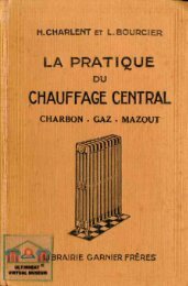
DEGREES<strong>FENWAL</strong>2500200015001000700600500Bi MetalSnap DiscThermostatFEATURESNonadjustable setpoint. Close tolerance.Up to 12 ampoutput.<strong>FENWAL</strong>INCORPORATEDAshland, Mass. 01721 617/881-2000 ULTIMHEAT (TEMPERATURE CONTROL SELECTOR CHARTUL ComponentRecognition.DifferentialExpansionThermoswitchControllerFEATURESAdjustable set point.0.1°F sensitivity.Slow make-break.Rugged construction.Various head styles.%" cartridge.10 amp output.High <strong>Temperature</strong>Models available.UL ComponentRecognition.CSA Certified.SurfaceMountingThermoswitchControllerFEATURESSmall size, lowcost. 10 amp output/120VAC adjustableset point.Surface mountingbrackets available.UL ComponentRecognition.LiquidExpansionThermoswitchControllerFEATURESUL ComponentRecognition.CSA Certified.VIRTUAL MUSEUMLiquidExpansion400 LineSingle or dual snapswitch. Travelling orIndependent Differential.FEATURESSingle or dual snapswitch. Travelling orIndependent Differential.Dual scale (°F & °C).4 Bulb styles. àPneumatic and Pro-'portioning modelsavailable.15 amps output.UL Listed and CSACertified.400300200PROBETYPENONINPICATirFMHIGH LIMIT100-100-200Page 17Page 11-13Page 14-15Price RangePage 18-20Page 21-26$5-$20 $28-$63 $5-$8 $29-$56 $120-$2322
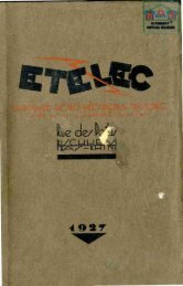
<strong>FENWAL</strong><strong>FENWAL</strong> INCORPORATEDAshland, Mass. 01721 617/881-2000 ULTIMHEAT®VIRTUAL MUSEUMTEMPERATURE CONTROL SELECTOR CHARTThermistor SensingThermocouple SensingSeries 194Series 551Series 550Series 550Series 5432500200015001000700600FEATURESON/OFF or Proportioning• SPDT orDPDT relay rated at10 amps or SPDMrated at 25 amps orDC output for solidstate relays.Field selectablevoltage inputs (120,208, 240 VAC).Sensor lead breakprotection.UL ComponentRecognition.Excellent controlover limited temperatureranges.FEATURESON/OFF or ProportioningControlModes . SPDT orDPDT relay rated at10 amps or DC outputfor solid staterelays.Field selectablevoltage inputs (120,208, 240 VAC).Sensor lead breakprotection.Large variety ofthermistor probesavailable.UL ComponentRecognition.Excellent controlover temp, rangesfrom -50 to 750 ! F.FEATURESTime proportionning.7 segment LED displayof process & controllerset point. Usesstandard type J or Kthermocouples.FEATURESDIN-Sized. Non-indicating.Deviationor Full scale indicating.Analog or Digital.SPDT or DPDTrelay rated at 10amps or DC outputfor solid-state relay.UL ComponentRecognition.Single or dual point.FEATURESSurface mounting orCustom installation.SPDT or DPDTrelay output rated upto 25 amps.Field selectablevoltage inputs.500400 **REMOTEREMMULTI-POINTMETER300\ ,...v ~FM APPROVEDHIGH LIMIT200tr 4 --m..TRIACOUTPUTDIGITALINDICATING100RELAYOUTPUTANALOGINDICATING100-200Page 29-32Page 27-28Page 27-28Price RangePage 27-28Page 33-34$52-$92 $85-$229 $92-$1313
<strong>FENWAL</strong><strong>FENWAL</strong>INCORPORATEDAshland, Mass. 01721 617/881-2000ULTIMHEAT ®VIRTUAL MUSEUMhow to get betterTEMPERATURECONTROLThis catalog discusses the various considerationsin designing a thermal system, suggestshow they can be applied, and outlinessome practical rules for designers.1. What is a Heated System?There are four elements in a heated system,all of which contribute in some way to controlperformance.A. Work (or Load): The material or productwhich must be maintained at a controlled temperature.The heat demand of the work may besteady; that is, the same material must be heldat constant temperature for a prolonged period,such as a culture in an incubating oven. Morecommonly, the heat demand of the work is variableand cyclic; that is, cold material periodicallyenters the system, absorbs heat, is removedand replaced by another batch of coldmaterial. An example of a variable system is amolding press which receives a batch of coolplastic, forms, cures and ejects it and repeatsthe cycle several times a minute.b. Heat Source: The device which deliversthe heat used by the system. The source maybe electrical heaters, oil and gas-fired heaters,or any other source. The process may be exothermic;i.e., generate its own heat.c. Heat Transfer Medium: The materialwhich transmits the heat from the heat sourceto the work. The material may be a solid, liquid,or gas. Its transfer characteristics play a largepart in determining how fast temperaturechanges are transmitted through the systemand, consequently, how closely the system canbe controlled.D. Controller: The instrument which <strong>controls</strong>the heat flow on the basis of the discrepancybetween the sensed temperature and the controller'sset point.2. A Practical Approach to AccuracyThe user of a thermal system is interested inone basic question: is the temperature controlaccurate enough to operate his product or processsatisfactorily? Control requirements are farless stringent in a waffle iron than in a crystaloscillator oven. Maintaining exact temperaturein a wax applicator tank is less critical than ina laboratory viscosimeter. The point is that exactcontrol of a system takes time, care andmoney. Moreover, it takes highly sensitivemeasuring instruments and indicators—andfrequent recalibration in service—to tell justhow good the control is. Eliminating the last degreeor fraction of a degree of temperature deviationis costly and should be done only forsound practical reasons.Nonetheless, good control is attainable withstandard instruments. To be sure, control willbe no better than the capabilities of the controller,but unless the system is designed as anentity, there is little assurance that the controllercan deliver what the user expects of it.3. What Affects Control Accuracy?System bandwidth and constancy of meantemperature are the overall measures of controlaccuracy. They are affected by many factors:1. <strong>Temperature</strong> Gradients—the range of temperaturevariation throughout the systemat any given instant2. Thermal Lag—the time delay for a temperaturechange in one part of the systemto be felt in other parts of the system (Seepage 5 ).3. Location of the Controller's Sensing Element—itsplacement relative to heatsource and load (See page 5 ).4. Response Speed and Sensitivity of theController—these and other characteristicsmake up inherent controller accuracy.They determine how well it is suitedfor a given application (See page ).5. Heat Balance—the capacity of the heatsource in relation to heat demand from thework, plus heat losses. Improper balancecan destroy control (See page ).How the Rest of the SystemAffects Control Accuracy1. Thermal GradientIf you were to measure the temperatures in athermal system at some instant, starting at theheater and progressing outwards to the edge ofthe system, you would find that the temperaturedrops progressively as you move farther awayfrom the heat source. This gradual drop existingin a system is called a thermal gradient.Every operating thermal system has agradient at all times. <strong>Temperature</strong> changes areoccurring continuously because of heater cyclingand heat losses, but these changes arenot transmitted immediately through the remainderof the system. As a result there is alwaysa temperature differential or gradient betweenpoints, with the highest temperature obtainedat the heat source and lowest at the outeredges of the system. Some gradient is essentialfor heat flow, since heat cannot flow unlessthere are areas of lower temperature to moveinto.Assume you have a metal bar containing aheater, sensing element and a pellet of materialrepresenting the work load. If you place a sensitivetemperature indicator at various points inthe bar and record the temperatures existing atthe beginning, middle and end of the operatingcycle, you would obtain three different temperaturecurves. These represent the temperaturegradient in the system at three instants duringits continuous cyclic change from minimum tomaximum steepness.Fig. 1A. Allow for Gradient When Measuringand Controlling <strong>Temperature</strong>. Becausetemperature varies along the gradient, itis important to measure temperature asclose as possible to the area you want controlled.If you place the thermometer betweenthe work and the heater, the reading will usuallybe higher than the temperature in the workarea. If you measure the temperature at a lowpoint in the gradient, for example, near the outersurface of the system, it may well be lowerthan the temperature at the work area.By the same reasoning, the set point of thecontroller must be adjusted according to itsrelative location. The closer to the heater youget, the larger the offset necessary to keep fromshutting off the heater too soon. For example, tocontrol the work at 300 degrees when the sensingelement is between the work and the heater,you may have to set the controller at 305 or 310degrees to enable the heater to reach a suf-
<strong>FENWAL</strong><strong>FENWAL</strong> INCORPORATEDAshland, Mass. 01721 617/881 -2000 ULTIMHEAT ®VIRTUAL MUSEUM[ distancFfia. 7ficiently high temperature to produce a usefultemperature rise at the work area.a How to Reduce Gradients. Althoughthermal gradients are inevitable and necessary,excessive gradients can be troublesome. Theycan be reduced in these ways (covered in detailin following section):1. Balancing heater capacity against heat demand.Gradients are influenced by the amountof heat input and heat losses. Too large an inputwill increase the gradient and the temperaturebandwidth.2. Proper setting and location of the sensingelement to control the duration of the heatcycle.3. Insulating the system to reduce heat loss.2, Thermal LagThe delay in the distribution of heat througha system is called thermal lag. It is present tosome extent in every system. It is influenced bythe distance between the heat source and thework, and the resistance to heat flow and heatcapacity of the heat transfer medium.Thermal lag is the enemy of accurate controlbecause it handicaps the controller. It withholdsfrom the controller for a certain interval—whichmay be as much as several minutes in somecases—information about temperature changesin the system. This lag can prevent the sensingelement from sensing heat demand soon enoughto deliver the heat when needed. It can also delaythe arrival of heat at the element so longthat the heater has delivered more heat than thesystem needs to recover from a temperaturedrop. The result in the first case is temperatureundershoot; in the second case, temperatureovershoot. Both can produce an undesirablylarge system bandwidth.Since thermal lag can never be entirely eliminated,one of the major prerequisites for closecontrol is to reduce lag to the largest extentpractical, and to compensate for the remainder.Thermal lag can be reduced by using materialsand techniques to speed up heat distribution.The remaining lag can be compensated for byselecting a controller of sufficiently fast responseand carefully placing its sensing elementat a point where it can sense importanttemperature changes quickly.Thermal lag can produce misleading informationfor evaluating controller performance in arapidly changing system. In certain systems thelag can be large enough so that, when the sensingelement is placed between the heat sourceand the work area, the controller may call forheat because of reduced temperature in its area,while the temperature at the work is just startingto rise as a result of the previous heatingcycle. This effect can seem even more pronouncedif the controller has a fast responsewhile the temperature indicator at the work hasa large inherent lag, such as is found in manymercury-in-glass thermometers.3. Selecting the Heat Transfer MediumThe selection of the heat transfer mediumhas much to do with the amount of thermal lag.Solids, liquids and gases are all used as heattransfer media, with metals probably the mostcommonly used. In most cases the choice is alreadyfixed by the cost, size, and application forthe thermal system. However, where close controlis the first consideration, the following evaluationof transfer media will be helpful. Theyare listed in order of decreasing preference forclose control, and, in some cases, there may beoverlap between individual materials in differentclasses.1. Well-agitated liquids2. Rapidly moving air3. High-diffusivity metals4. Low diffusivity solids5. Stagnant air6. Stagnant liquids4. Proper Location ot ComponentsBy now it should be clear that a controllerperforms no better than the system permits.Thermal lag is one of the major factors in handicappingthe controller. Lag can be reduced byproper choice of the heat transfer material. Itcan be further reduced by a wise matching ofthe controller with the application and by placingthe components correctly in the system.Correct placement is essential, because startingwith the same heat source, controller and thermalload, you will obtain widely different controlaccuracies depending on the relative locationsof these components.If the heat source, sensing element and workcould be always grouped into a compact area,there would be little problem with control. Theshort heat path from the heater would enablethe sensing element to respond quickly to temperatureincreases at the heater, cyclefrequently and minimize overshoot.In the majority of cases this intimate groupingof system elements is not feasible due to therelatively large size of the system and the factthat the heat source is at some distance fromthe work area. The problem then arises as towhere to place the sensing element, becauseFig 3moving it away from either the heater or loadaffects control in some manner. There is nosingle answer to the problem. The designer'sproblem is to arrive at the best compromise forhis thermal system.When the work and the heat source are separated,placement of the sensing element involvescompromising the advantages of smallestbandwidth and constant mean temperatureat the work area. Both cannot be attained at thesame time. You must decide which of the twotypes of accuracy is more important for yoursystem.A. Importance of Cycling Frequency. Precisionperformance of ON-OFF <strong>controls</strong> requiresfrequent cycling of the heat source. (In systemsusing other than an ON-OFF control mode,frequent cycling is unnecessary.) Rapid cyclingproduces a series of short bursts of heat whichapproximates a steady heat input at the load.Infrequent cycling, on the other hand, causesprolonged heating intervals in which largequantities of heat enter the system. This resultsin wide variation in thermal gradient during theoperating cycle and undesirably increases thesystem bandwidth.Although rapid cycling is desirable becauseit reduces bandwidth, there are practical limitsto be considered. Excessive cycling decreasesthe service life of contacts and mechanicalcomponents of the controllers, relays, heaters,and other cycled components. The optimumcycling frequency is one that produces the desiredsystem bandwidth without excessive wearon the cycling components.Cycling frequency can be reduced by movingthe sensing element away from the heat source.If this is not practical, you can reduce it by increasingthe thermal lag to the element by someartificial means, such as insulating the elementwith a strip of asbestos, a heat shield or a reflectingstrip.Rapid advances in the state of the art of solidstate electronic devices such as silicon controlledrectifiers and thyristors allows their directreplacement for mechanical relays andcontrollers in electrical heating. These solidstate devices can be switched rapidly withoutthe mechanical problems of wear and servicing.However, initial installation costs are somewhathigher.
<strong>FENWAL</strong><strong>FENWAL</strong> INCORPORATEDAshland, Mass. 01721 617/881 -2000iULTIMHEAT ®VIRTUAL MUSEUMa Preferred Component Location forVarious Thermal Systems. Although in practicethermal systems are not purely steady orvariable, they usually are predominantly one orthe other. For such systems, the following ruleof thumb will be helpful: where the heat demandis relatively steady, the sensing elementshould be placed closer to the heat source;where the demand is largely variable, it shouldbe nearer to the work area.c. Liquid and Gas Systems. In liquidbaths and ovens where the heat demand is primarilysteady, locating the sensing element fairlyclose to—and above—the heat source shouldminimize bandwidth. In the arrangement illustratedin Figure X, the element is in an undesirableposition because the slowly moving convectioncurrents take too long to reach it By thetime the controller can turn off the heater, toomuch heat has already been generated andovershoot becomes inevitable. Agitation and/ordistribution of the heat sources over the bottomof the tank will help shorten the lag in heattransmission, increase temperature uniformityand improve control. However, the narrowestbandwidth will be obtained with the arrangementillustrated in Figure Y. Bringing the sensingelement closer to the heaters further reducesthermal lag, while the agitator promotes uniformmixing and reduces heat gradients.Figure Z shows an analogous situation forovens. Generally, the best location for the sensingelement is fairly close to the heating elementsto reduce the transfer lag of the convectioncurrents. It may have to be movedcloser to the center of a large oven, where theheat source is also large, to lower temperatureoffset to a point where the temperature will bemore representative of the entire oven. Whereverfeasible, blowers should be installed toprevent temperature stratification and eliminatestagnant air pockets around the sensing elementwhich can insulate it and slow its response.Multiple heaters or coils distribute theheat faster and more uniformly than a singleconcentrated source, and are preferable for thatreason.5. Insulation is Important ^Proper insulation has the double-barreled advantageof reducing heating costs while improvingcontrol accuracy.Besides saving heat another important functionof insulation is to minimize temperaturegradients within the system. Although gradientscannot be eliminated entirely, they should be assmall as possible to keep the temperaturenearly uniform throughout the system. Reductionof gradients also lowers the offset requiredfor the controller setpoint, and produces a narrowersystem bandwidth as the heaters cycle.Best temperature control with minimum heatinput is obtained when the thermal conductivitywithin a system is high but the conduction ofheat away from the system is low. For this reasonthe system should be thermally insulatedfrom any supporting structures which will carryaway heat and increase the gradient This isparticularly important where the heated mass isrelatively small compared with the supportingstructure; for example, a heated platen in alarge press.^ftFig.ZHow to Heat the System1. Sizing the Heat SourceNo ON OFF system can be controlled accuratelywithout proper heat balance. Heat balancerefers to the relationship between the capacityof the heat source and the heat requirementsin a given system. For best control, theheat should be on 50 percent of the time whenthe system is at the desired operating temperature.The three curves in Figure 4 illustrate theeffect of heat balance on temperature control.Curve (A) shows what happens when the heatsource is too large. The temperature of the systemrises sharply each time the heat is turnedon, causing repeated thermal overshoot witheach cycle. Curve (B) illustrates the control in abalanced system (heat-on 50% of the time).Note that the rates of heating and cooling areapproximately equal and the deviations from thecontrol point are small and equal. Such a systemwill be flexible enough to maintain goodcontrol even if the heat demand should increaseor decrease by a fairly substantial amount.Curve (C) shows what happens when the steadyheat demand exceeds the heater capacity. Eventhough the heater is on continuously, the systemnever reaches control temperature. Even ifthe heat is ON 50% of the time under normalcircumstances, more than double this amount ofheat may be required if low voltage combineswith cool breezes or fans. Allowances must bemade for this factor when selecting heaters toobtain an actual 50% ON time.It is seldom possible to obtain perfect heatbalance in normal industrial operations. However,whenever the heat source is on mere than60% of the time, the heater rating should be increased.If the heater is on less than 40% of thetime, the rating is too large and should be decreased.Procedure for Proper Sizing of the HeatSource. Two factors enter into determining therequired heater rating: (1) the amount of heatneeded to bring the system up to operating temperaturefrom a cold start within a specifiedtime, and (2) the amount of heat required to satisfythe demand of the system (including losses)during normal operation. Usually the largerof the two will determine the minimum rating.However, where the warm-up requirements arerelatively large, special techniques to handlewarm-up conditions can be used.2. Heater SelectionThere are many heating methods available,such as steam or hot-water jackets or coils,Dowtherm and similar heat exchangers, as well
<strong>FENWAL</strong><strong>FENWAL</strong>INCORPORATEDAshland, Mass. 01721 617/881-2000Fig. 4 Effects of heatbalance on temperaturefluctuations in a thermalsystem, resulting fromuse of: a, too large aheater; b, the right capacityheater; and c, toosmall a heateras radiant and direct contact heaters.A. Installation Method. The manner inwhich the heaters are installed can affect uniformityof heat distribution, rate of heat build-upand heating costs in the system, as well as determinethe configuration and rating of heatersto be used. The more intimate the contact betweenthe heaters and the material or part beingheated, the better is the heat conductivity. Goodconductivity improves temperature control andlengthens heater life. The usual methods of installingheaters, listed in decreasing order ofheat conductivity are:1. Cast integral with metal or immersed inliquids or gasesSelecting the <strong>Temperature</strong> ControllerGood temperature control depends on manymore factors than the performance of the controlleralone. Nevertheless, the type of controllermust fit the application if the system or equipmentis to operate within the required accuracylimits. The process for choosing a controllershould be based on the following considerations.1. What to Look ForA. <strong>Temperature</strong> range: the operating rangeof most controllers is limited by one or more ofthe following factors: type of sensing element,type of liquid fill, mechanical design or constructionmaterials. The system operating temperaturesshould fall well within the controller'soperating range, leaving leeway for possibleover and undershoots.a Resolution sensitivity: this factor—onemeasure of controller quality—states theamount of temperature change that must occurbefore the controller will actuate. It may be expressedeither as a specified number of degreesor as some percentage of the controller's operatingrange or scale.In the majority of controllers, the sensitivityis some fixed value, but in many higher-qualitycontrollers the sensitvity can be adjusted over arange of values to provide greater flexibility.The better the sensitivity, the narrower the systembandwidth produced, all other conditionsbeing equal. However, to translate good controllersensitivity into correspondingly accuratecontrol calls for careful designing, heating andinsulating of the system as well as relativelyhigh cycling rates. For these reasons, unless itis actually needed, high sensitivity should notbe the only consideration. In most applications(a) Excess/ve heat (t>) Balanced heat (c) Insufficient heatTime »2. Inserted in hole drilled in metalSet point3. Placed in groove in surface of metal4. Wrapped around or clamped to the surface5. Spaced away from surface being heated(except for radiant heaters)Heaters are manufactured in a variety ofshapes and forms to fit the type of installation.Cartridge, strip, ring, tubular and immersion arecommon configurations.a Selecting the Proper Sheath MaterialThe resistance element and outer sheath ofaheater are designed for service within certaintemperature limits. If the heater is operated consistentlyat excessive temperatures, the heatinga controller having a sensitivity of from 2-5°Fwill be adequate, if it is properly installed andused.g Speed of response: this factor is a measureof the time it takes for a temperature changeoccurring at the sensing element to be translatedinto a controller action. This is a distinctlydifferent concept from resolution sensitivity because,even though two controllers may beequally sensitive, they may not necessarily respondwithin the same time.Response time depends to a large extent onthe operating principle of the controller. For example,a THERMOSWITCH® control will respondconsiderably faster than an ordinary thermostatwith an enclosed bi-metallic element, becauseits shell is the temperature-sensing element.The housing of the enclosed-element type, onthe other hand, acts as a barrier which slowsup heat transfer and increases response time.Liquid-filled systems are more rapid than gasfilledsystems, because liquids have higherthermal conductivities and thus respond morequickly to temperature changes. Thermo-electricsensing elements are the most rapid of all.In general, response time will be low for sensingelements having low mass (e.g., the thermistor),and a short heat transfer path betweenthe temperature to be sensed and the actualsensing member (e.g., the THERMOSWITCH design).In addition, the probe should be as thinas possible and fabricated from a good thermalconductor.Fast response is important in two types ofapplications: (1) where the system temperaturechanges rapidly and frequently; (2) where theheat transfer medium is a relatively poor conductor,such as gases or slowly-circulating liqelementwill fail prematurely and the sheathmetal will deteriorate rapidly.Corrosion problems must also be consideredwhen selecting the proper sheath material.When working with corrosive or oxidizing materials,it is vital to select a sheath material thathas good corrosion-resistance at the temperaturesin question. For unusual service requirements,consult the heater manufacturer.C Selecting Proper Watt Density. Becauseof differences in heat absorption and heattransfer, there is a limit to the rate at whichvarious types of materials can be heated safely.If the heating rate is excessive, the area aroundthe heater will become overheated. This localizedoverheating may deteriorate the materialbeing heated and damage the sheath and heatingelement.Heaters are rated on the basis of watt density,which is the number of watts producedper square inch of heated sheath surface. Thehigher the absorption rate of the material, thehigher the permissible watt density for the heater.To aid in selecting a heater which will producea safe heating rate, most heater manufacturerspublish recommendations on allowablewatt densities for various situations.uids. Speed of response is less important wheretemperatures remain relatively constant for longperiods, where highly accurate control is notessential, or where proportional control is used.D. Sensing element dimensions: thesevary depending on the operating principle of thecontroller. Of the commonly used industrial controllers,liquid-filled controllers are available ina variety of sensing element configurationsranging from long, thin, to short, squat types,and can be adapted to many installation requirements.Where space is a critical consideration,a midget or miniature THERMOSWITCHunit, or a thermistor element no bigger than acommon pin, will solve the problem.a Method of adjusting setpoint: wherethe sensing element must be placed in a locationthat is difficult or hazardous to reach, thereis little alternative to using a remote-settingcontroller to adjust the setpoint. Bulb-and-capillarycontrolls can be furnished with capillarylengths of 10 ft or more; thermistor controlleads can be 200 ft long. However, whereveradjustments will be accessible while the systemis operating, a local-bulb type controller is agood choice, and will be more economical.F. Control mode: this refers to the methodin which the controller attempts to restore systemtemperature to the desired level. The twomost common methods are two-position (on off)and proportioning (throttling) control. Two-positioncontrol results in a certain amount of overand undershoot which may be excessive undercertain conditions. Proportioning control providesone method for preventing overshoot bytailoring the size of the correction to the amountof temperature error. Some Fenwal controllersare designed to operate as on off <strong>controls</strong>; oth-7
<strong>FENWAL</strong><strong>FENWAL</strong>INCORPORATEDAshland, Mass. 01721 617/881-2000IISULTIMHEAT ®VIRTUAL MUSEUMers operate in both the on-off and proportioningmodes. The advantages and limitations of eachcontrol mode will be discussed in detail in a latersection.2. How <strong>Temperature</strong> Controllers WorkThe operating principle of a controller cantell a great deal about the performance to expect.Most of the commonly-used industrialtemperature controllers today are based on oneof three operating principles. These are: differentialexpansion of metals; fluid expansion; andelectronic. Fenwal manufactures controllers ofeach type.A. Differential expansion controllers:This familiar principle of sensing temperaturemakes use of the fact that dissimilar metals undergounequal changes in length with a givenchange in temperature. The sensing element ina common class of thermostats consists of twopieces of dissimilar metals fabricated into astrip, coil or disc. As the temperature changes,the element tends to warp or distort and the resultingmotion can be used to operate a circuitby moving an electrical contact toward or awayfrom a mating contact. This motion can also beused to overcome the force of a spring-loadeddetent, which will actuate a snap switch.A refinement of the differential-expansionprinciple is the strut-and-tube thermostat, suchas the cartridge THERMOSWITCH unit, and itsmidget and miniature counterparts. In this design,the bimetals are not bonded together intoa single element, but comprise two basic partsof the thermostat The outer shell is made of thehigh-expanding material, usually brass or stainlesssteel and the strut assembly is made froma low-expanding metal, usually a high nickel alloy.The strut assembly, on which a pair ofelectrical contacts are mounted, is installed inthe shell under tension or compression dependingon whether the maximum overshoot capabilityor maximum setting range is desired. Becauseeach end of the strut assembly is mechanicallyconnected to the ends of the shell, anet change in force is produced on the low-expansionstrut assembly as the high-expandingshell expands or contracts with changing temperature.The amount of shell movement necessaryto cause the contacts to open or close isset by an adjusting screw and since this movementis a direct function of temperature, thescrew settings determines the control temperature.This adaptation of the differential-expansionprinciple gives several important controladvantages:1. Because the outer shell is the active temperaturesensing member, and not merely ahousing, response to temperature change is almostinstantaneous.2. This shell and strut arrangement has "anticipation1 ' characteristics, which substantiallyreduce the amount of over and undershoot underconditions or rapid temperature change. Anticipationis produced by an inherent time lagbetween the shell and internal struts, whichcauses the shell to "lead" the stuts by an intervalthat varies directly with the rate of temperaturechange. With rapid temperature rise, theshell exerts a larger net force on the struts and8tends to pull them apart sooner than would bethe case when the temperature is rising slowly.The result is several degrees or more of anticipationwhich help produce closer control.3. The strut-and-contact assembly operatesby slow make and break, which means that everytemperature change, no matter how small,causes a corresponding change in the spacingbetween the electrical contacts. This meansthat contact action can be produced by a verysmall temperature change, which accounts forthe excellent resolution sensitivity (0.1 F) ofTHERMOSWITCH <strong>controls</strong>. On the other hand,thermostatic units whose contacts are actuatedby a snap switch or similar detent action, havesensitivities of several degrees since a finiteamount of energy must be absorbed to overcomethe restraining forces on the contact assemblyand thus produce contact actuation.4. Since the strut assembly is assembled undertension or compression, a properly installedunit has excellent vibration resistance and willoperate reliably and accurately under difficultphysical conditions.All current-carrying devices tend to heat upas the current load increases. This is also trueof THERMOSWITCH units. As current loadacross its contacts increases, the heat generatedis largely absorbed by the strut assemblyon which they are mounted. Heating the strutassembly has the same net effect of raising thesetting of the controller. For this reason, althoughthe control will handle loads up to 10amps, it produces best control at more conservativeloads. Where the loads are greaterthan 3 to 4 amps, much better results will beobtained by using a relay as the load-carryingelement with the control handling the pilot load.Another alternative, where electrical load exceeds3-4 amps and the operating temperatureis applicable, is to use the Series 20000 liquidfilledthermostat. In this unit the current is handledby a snap switch so that the size of thecurrent load has little effect on the controlleraction.a Liquid-filled controllers: if a small containeris completely filled with an incompressibleliquid, the volume of the liquidwill change with the temperature. If the containeris somewhat elastic, such as a bellows, itwill move in response to the changing volumeof the liquid. The motion of the bellows canthen be transmitted through a push rod or mechanicallinkage to actuate the contacts of anelectrical switch. By setting the height of theswitch with an adjusting screw, the amount ofpush rod travel required to operate the switchhencethe operating temperature of the unitcanbe controlled.There are two basic types of liquid-filled temperaturecontrollers. The first is the local-bulbthermostaL An example of this type is theSeries 20000 unit in which the sensing liquid,bellows and push rod are all enclosed in a cylindricalshell which is inserted directly in theprocess. At the top of the shell is the head ofthe unit containing the control switch and leadwires. This type is non-indicating.The second type is the bulb-and-capillarycontroller. In this type the expansible liquid iscontained in a metal bulb which is the sensingelement. The pressure from the expanding fluidin the bulb is transmitted hydraulically to thebellows through a thin capillary tube, 6-10 ftlong, also filled with the expansible fluid. A separatehousing, located remotely from the bulb,contains the bellows, actuating mechanicallinkages, indicating mechanism and <strong>controls</strong>witches, etc. A typical bulb-and-capillary controlleris the 400 Line (indicating).The liquid-filled local bulb thermostat is intendedto supplement not replace, the differential-expansionTHERMOSWITCH design.While the liquid-filled thermostat is inherentlyless sensitive, the use of snap switches to carrythe electrical load simplifies the circuitry. Theload carrying characteristics of both the localbulband bulb-and-capillary controllers arequite versatile, since their snap switches can beinterchanged for various types of service, including20 amps at 120 or 240 volts AC, as wellas narrow differential, high inrush and manualreset In addition, switches can be paired toproduce control action at two selected temperatures.In the 400 Line controller, the two-switcharrangement can be furnished to permit individualsetting or constant differential between thetwo settings, with indication of one or both settingsas well as the process temperature. TheFenwal 400 Line also includes a proportioningpotentiometric output controller which provides"straight line" control when used with proportionalpositioning motors or valves.c. Thermistor-Actuated controllers:these controllers, exemplified by the FenwalSeries 194, represent a relatively new developmentin temperature control techniques. Theseare temperature controllers actuated by athermistor sensing element connected by leadwires to an electronic amplifier, indicating circuit(if present) and control circuit all containedin a separate housing or chassis. These controllersoffer unusual advantages. They arehighly accurate and mechanically rugged, haveexcellent stability with age, utilize a small sensingelement require infrequent calibration andcan be located up to 200 ft or more from thesensing element using standard electrical conductors.This performance results from the remarkableproperties of the thermistor.The thermistor is a semi-conducting materialmade into tiny beads or other shapes by sinteringa mixture of metallic oxides. One of the outstandingattributes of the thermistors is thattheir electrical resistance decreases rapidly perdegree of temperature rise. Compared with thesensing elements used in other types of temperaturecontrollers, i.e., resistance bulbs andthermocouples, thermistors produce a verylarge working "signal." Some thermistors undergoa thousandfold change in resistance between100 and 600 F, while a resistance bulbmay change in resistance by a factor of only 2over the same temperature range. The output ofthe commonly used iron-constantan thermocouplevaries over an even smaller range of valuesat these temperatures.Since a relatively small change in temperatureat the thermistor produces a large changein resistance, the controller has unusually good
<strong>FENWAL</strong><strong>FENWAL</strong>INCORPORATEDAshland, Mass. 01721 617/881-2000 ULTIMHEATVIRTUAL MUSEUMsensitivity capable of producing stable controlwell within 1°F in a properly designed system.The sensing and control circuits are relativelymore compact, less subject to mechanicalshock and generally require less maintenancethan those used with a thermocouple or resistancebulb.D. Thermocouple Actuated Controllers:exemplified by Fenwal Series 543 and 550 representthe latest developments in solid-stateelectronics employing integrated circuits andrelay or solid-state thyristor outputs. Thethermocouple sensor consists of two wires ofdissimilar metals joined at one end called the"hot" or measuring junction, while the otherends become the reference junction. The referenceor "cold" junction is held constant at either32°F (melting ice) or calibrated to anequivalent EMF value. The temperature or differencebetween the hot and reference junctionsdevelops a DC millivoltage that is linear withtemperature within a few degrees. This signal isfed into a bridge balance potentiometer whichmeasures the EMF output and, with amplificationto a useful level, <strong>controls</strong> process temperaturethrough the operation of a relay or solidstatedevice.The overall thermocouple range is -300°F toapproximately 4000°F and is derived from severalbase metal combinations such as iron/constantan,copper/constantan, chromel/alumel andnoble metal combinations of platinum or platinum/rhodiumwith rhodium in varying percentages.Thermocouple wires are available in commercialand premium grades with wire errorlimits within 2 F. Thermocouple sensors generallyhave a response time about ten times betterthan a resistance temperature detector and aretip sensitive.E. The Platinum Resistance <strong>Temperature</strong>Detector (RTD): differs from a thermocouplein that a finely wound platinum wirechanges its resistance directly with temperature.This eliminates the need for dissimilarmetals and cold junction compensation.Mounting may be similar to that of thermocouples;protection from stress or corrosive environmentsis achieved by encapsulation and/orinstallation in thermowells. Two, three or fourleads may be provided with connection to aWheatstone bridge circuit being common. Caremust be exercised to avoid resistance changefrom excess current or heat conducted to theresistance bobbin along its leads.3. Types of Control ActionA. On/Off (two position)B. Proportioning (throttling)C. Proportioning plus Integral (automatic reset)D. Proportioning plus Integral plus Derivative(rate)A. On-off control: in on-off control the controllerpermits the controlled element (heater,valve, etc.) to be completely ON or OFF, open orclosed. No intermediate position is possible. Asa result, the size of the corrective action has norelation to the amount of temperature deviation.Full heat (or other action) is supplied regardlessof whether the temperature is 2° or 20° belowthe setpoint. The heat stays until the controllersenses that the system temperature correspondsto the setpoint (or more accurately, thehigher limit of the controller's operating bandwidth).The end result of two-position control is thatthe system temperature oscillates continuouslyabove and below an "average" system temperature.The size or amplitude of these oscillationsdetermine the system's bandwidth and they aregoverned by many design factors which havealready been discussed.1. Adjustable differential: most on-off controllershave a fixed operating differential, butin some more elaborate controllers the operatingdifferential can be varied to suit the application.Operating differential is the "dead zone"or the difference between the temperatures atwhich the controller opens and closes its contacts.The chief advantage of increasing the operatingdifferential is to decrease the cycling rateand thus the wear on switches, heaters and othercycled components. However, reduced cyclingaffects control.Since the system bandwidth is strongly influencedby cycling frequency, the operatingdifferential of a controller, if adjustable, shouldbe increased judiciously. The best choice is theone which will reduce the cycling frequency ofthe equipment as much as possible, withoutproducing an excessive temperature bandwidthin the system.B. Proportioning control: in proportioningcontrol the controller "recognizes" the deviationfrom the setpoint and proportions the correctiveaction to the size of the deviation. The proportioningaction occurs when the system temperaturefalls within a range of temperatures knownas the proportioning band. At the approximatecenter of this band is the desired system temperature.In true proportioning control, the controlledelement, for example a valve, can be moved toany position from 0 to 10CP/o open, as requiredby the size of the deviation from the controlpoint.The virtue of proportioning control is that thesystem temperature does not oscillate continuouslyaround the desired value, as it does inthe case of on-off control. Since the correctiveaction is tailored to the size of the deviation tobe corrected, the system has less opportunity toovershoot or undershoot. This action is particularlyhelpful in systems which go throughfrequent work cycles where the system iscooled down by the addition of cold materialand then must be brought up to temperaturequickly. Under these conditions, the temperaturetends to overshoot in each recovery cycleand the throttling action of proportioning controlis most helpful in combating this tendency.1. Selecting the proper proportioning band:ideally the proportioning band for any particularsystem should be just wide enough to accommodatethe time lags in the system.The proportioning band for a given systemcan be established by operating the system atthe desired temperature with the controllerfunctioning on the on-off control mode at minimumdifferential and noting the limits of overshootand undershoot encountered. The proportioningband should then be set to just exceedthese temperature excursions.2. Droop: there is, however, an inherent limitationin proportioning control. The size of thecorrective action depends only on the size ofthe difference between the system temperatureand the setpoint. But this corrective action canfit only one set of equilibrium conditions. A proportioningcontroller cannot correct the valveposition without a change in sensing elementtemperature. This will result in the systembeing controlled at progressively lower temperatureshaving, in effect, a "droop."However, by the nature of proportioning control,the droop cannot go below the lower limit ofthe proportioning band under normal operatingconditions. Thus, a narrowing of the band willreduce droop. Droop can be corrected by resettingthe setpoint above or below the original settingor by rotating a manual reset adjustment (ifprovided) so that the system stabilizes at thedesired temperature. Droop also can be correctedby adding INTEGRAL ACTION or automaticreset to the controller.In this variation (PI), the integrator adds asignal to the controller action so that the outputof the controller is proportional to the time integralof the input. In other words, reset recognizesthe deviation between actual process temperatureand setpoint and supplies a signal tocorrect for this deviation. This signal moves theproportioning band up or down to cause agreementover a period of time. By design, reset actionoccurs only within the proportioning band.This type of operation is termed to have antiresetwindup which prevents a large resetcharge causing overshoots on startup.4. HELPFUL HINTS FOR ADJUSTING PRO-PORTIONING CONTROLLERSA. Rapid cycle time provides better controland prolongs heater life; if relay output is used,relay life is shortened.B. Bandwidth should be adjusted so that oscillationsjust cease. Wide bandwidth providesstable control, but droop is larger.C. Automatic reset adjusted properly eliminatesdroop. Too fast a reset rate causes unstableoperation (system oscillates). With toolittle reset rate, system response is slow.D. If rate time constant is too short, overshootoccurs (virtually no rate). If rate time constantis too long, oscillations can be caused byon-off action.E. System Startup: Adjust reset for lowestrepeats per minute (largest reset time) and ratefor shortest time. This is essentially proportioningonly control. Adjust reset in incrementalsteps so that droop is eliminated with minimumamount of oscillations. Adjust rate so that slightpower line changes are nullified in shortest periodof time without oscillations.9
<strong>FENWAL</strong>General Operating Techniques1. Preventing Overshoot During Warm-UpIn many thermal systems the temperaturemust never exceed a certain maximum, in suchsystems the possibility of overshoot, particularlyon initial heat-up, can be a serious problem.A. Anticipation: two types of controllerscan produce the anticipation needed to preventovershoot during warm-up cycles: proportioningand differential expansion. Proportioningcontrol is, of course, highly effective since itcontinuously reduces the heat input as the temperaturerises toward the setpoint. The advantagesand limitations of proportioning controlhave already been described.When the expense of a proportioning controlis not justified, the differential expansion THER-MOSWITCH unit will produce a considerable degreeof anticipation. The amount of anticipationproduced increases with increasing rate of temperaturechange in the system. Where overshootis a particular problem, various THER-MOSWITCH units can be supplied to producethe desired degree of anticipation for any particularapplication.Location of the thermostat with respect to theheater also will affect the amount of anticipation.The shorter the distance between the heaterand thermostat, the greater the anticipationeffects.B. Extra warm-up heaters—single thermostatcontrol: another approach to obtainingrapid warm-up without overshoot is to use twosets of heaters. The circuit is connected so thatthe heaters will operate during the warm-upcycle, but when the control temperature isclosely approached or reached, one of the heatersis switched out of the circuit leaving sufficientcapacity to deliver the basic controlheat Both heaters can be operated by a singlethermostat, provided some switching mechanismis inserted to reduce heat input after thefirst cycle. For example, during warm-up one ofthe heaters can be connected to a holding relayin series with the temperature controller. Afterthe first controller cycle, the relay and its associatedheater drop out of the circuit.Another way to reduce warm-up heat usingjust one thermostat is to reduce the voltagesupply after the warm-up interval. This can beaccomplished by using a voltage selector relaywhich switches the power supply from 220volts to 110 volts after the first cycle. If desired,a variable transformer can be inserted in thelow voltage power supply line to provide exactlythe proper voltage for the heat output requiredby the application. Relay action can alsobe applied in other ways, such as changing theconnection of two heaters from parallel toseries.This general technique of using high heatingcapacity for warm-up has one significant limitation.The higher heating rate during the firstcycle tends to exaggerate overshoot to someextent This can be reduced by installing one ofthe warm-up heaters close to the thermostat, soas to produce an extra amount of anticipation.Since this heater will be inoperative after the10<strong>FENWAL</strong>INCORPORATEDAshland, Mass. 01721 617/881-2000warm-up interval it will not produce excessiveanticipation which might interfere with controlunder normal.operating condition.c. Extra warm-up heaters—two thermostatcontrol: the use of two thermostats, insteadof one, can permit rapid warm-up withouteither producing overshoot or requiring anycompromises in control during the normal operatingcycle. The added thermostat is set to actuateat a temperature lower than the desiredsystem temperature and switches off the warmupheaters at some selected temperature. In theinterest of reducing warm-up time, the setpointof this thermostat should be as close as possibleto the control temperature without producingovershoot The warm-up thermostat and itsheaters should be electrically independent ofthe control heaters and their thermostat. Anotheralternative is to use a step-down voltagesupply arrangement to supply the heaters, usingthe warm-up thermostat to switch from thehigh- to the low-voltage source through a relay.2. Installation and Service TipsOne of the truisms of control is that the controllercan respond only to what its sensing element"sees." Here are some important pointswhich will insure that the sensing bulb does itsjob accurately.A. Proper location of sensing element: inan earlier section we discussed at length the effectof locating the bulb at various points betweenthe heat source and the load.In large chambers and long ovens, wherethere is a continuous flow of work in and out, itis sometimes impossible to place the sensingelement at a point where the temperature is reasonablyrepresentative of temperatures elsewherein the system. This creates a problemwhen the temperature of the work must beclosely controlled during the entire process. Insuch cases control can be improved by usingseveral controllers, each controlling a group ofheaters, spotted at intervals along the directionof travel. In this way each controller can be responsiveto the temperature existing at its particularlocation, and no undue reliance is placedon the ability of any one sensing element to respondto temperature changes at remote points.Remember that temperature gradients exist inevery system and unless it is placed right at thepoint where the temperature must be controlled,the setpoint of the controller will have to be offsetto compensate for the temperature differenceexisting at the sensing element's location.a Good installation practice:1. Immerse the bulb completely. The sensingelement must be completely immersed in thecontrolled medium, whether gas, liquid or solid,in order to give accurate response. If it is onlypartly immersed, the temperature reported tothe controller may not be the actual temperaturein the system, but an average of system temperatureand the temperature around the exposedsurface of the element It should be insulatedfrom brackets, bushings, etc., which arenot at the same temperature as the bulb orwhich can conduct heat away to cooler parts ofthe structure. Otherwise it will be cooled andsense a lower temperature than the one actuallyexisting.2. Help the sensing element to "see." Anycondition which tends to insulate the sensingelement will slow down its response and introducecontrol inaccuracies, regardless of howgood the controller is. When installed in anoven, the element must be installed where it isexposed to moving air and should not be buriedin brick work, oven walls or shielded by somestructure which will prevent its full length frombeing exposed. It should be placed so that itcannot be covered by accumulations of dirtscale, sludges or any other materials that willinsulate it from the process. Where such as accumulationdoes occur, clean the sensing elementas often as necessary.When the sensing element is imbedded in asolid, such as a platen, bearing, etc., thereshould be minimum clearance between it andthe solid. Any air space will act as an insulator.The element should contact as much of the surfaceas possible. Thus, it should be cylindricalover its entire length, rather than tapered, topermit complete contact with the sides of thesocket A special heat transfer compound canalso be used to fill in voids and irregularities inthe hole.In liquids and gases, good heat transfer betweenthe sensing element and the medium canbe obtained only if the fluid is moving fast. Forthat reason, the element should be placed in anactive moving stream which is part of the generalcirculation of the system. In addition, withoutgood circulation, there will be hot and coldspots in the system as well as a large sensinglag.Do not locate the sensing element close to orparallel with walls and ducts that may be considerablyhotter or cooler than the gases or liquidsflowing past it Watch out for radiationfrom hot surfaces or from the heat source impingingdirectly on it. This type of radiation canmake the element considerably hotter than theactual temperature around it and cause whatappears to be an offset in calibration. If it is notpossible to avoid radiation by relocation, installa shield to intercept the radiation before it canheat the element.3. Physical protection: install the sensingelement where it cannot be knocked or jolted bymoving parts of the system, doors, trays, etc. Toprotect it against corrosion and chemical attack,use stainless steel sensing elements andcapillaries or install it in a thermal well of acorrosion-resistant metal.Besides protecting the sensing element thermalwells are a great convenience wherever itmust be inserted through a tank wall, since itcan be removed for replacement or adjustmentwithout draining the tank. To insure good heattransfer, make certain it fits snugly in the well.Where the clearance is excessive, fill the airgap with a conducting material, such as graphitemetallic filings or powder. Occasionally,open wells, which are simply open-end pipes,are used to protect capillaries from vapors andother undesirable materials which lie on thesurface of a bath. The top of the well should behigh enough above the liquid to keep the capillaryout of range of the vapors.ULTIMHEAT®VIRTUAL MUSEUM
1<strong>FENWAL</strong>THERMOSWITCH®TEMPERATURECONTROLLERSThese Fenwal THERMOSWITCH Units are strut-and-tube typethermostats comprised of two basic parts (1) the outer shellmadeof high expanding metal and (2) the strut assembly—madeof low expanding metal.A pair of electrical contacts is mounted on the strut assembly andinstalled in the shell under tension or compression. Because eachend of the strut assembly is mechanically connected to the endsof the shell, a net change in force is produced on the low-expansionstrut assembly as the high-expanding shell expands orcontracts with changing temperature. The temperature at whichthe contacts make or break can be regulated by a temperatureadjusting sleeve.<strong>FENWAL</strong> INCORPORATEDAshland, Mass. 01721 617/881-2000 ULTIMHEAT ®Typical ApplicationsHydraulic Laminating PressesLabel Adhesive ApplicatorsDeep Fat CookersRespiratorsVending MachinesMilk PasteurizersAnchor PinPointsVIRTUAL MUSEUMTypesetting MachinesLivestock Watering FountainsTextile PlatensPaint Drying EquipmentHot Stamp PrintersTropical Fish Tanks<strong>Temperature</strong> AdjustingSleeve>Series 17000 CartridgeThis unit may be inserted in a %" reamedhole. If reamed hole is used, a short splineshould be added to receive locating pin onthermostat—this prevents thermostat fromturning when the temperature adjustingsleeve is turned.Series 17100Hex Head"UL Component recognized unitsnot rated for DC operation.r-3.7181 0628-10 It*".375 TO .625AT ROOM TEMP.CATALOGNUMBER17000-017021-017002-017023-0TEMP.RANGE*-100 ° to400" F-100° to600 FCONTACT OPERATIONON TEMP. RISEOPENSCLOSESOPENSCLOSESSHELL ANDHEAD MATERIALALLBRASS321as. SHELLCURRENT RATINGS(MAX. RESISTIVE)AC10 amps@120 volts5 amps@240 voltsDC'2 amps@28 volts2 amps@120 voltsHas all the internal features of the CartridgeType above with the addition of a standardpipe thread for mounting purposes. A dial,knob and armored cable over lead wires canbe supplied with this model.y214 N.P.T.p.618r~ 2.968x 031-4.281- 062.375 TO .625AT ROOM TEMP.17100-0 -100° to400° F17121-017102-017123-0-100° to600° FOPENSALLBRASSCLOSESOPENS 321S.S. SHELLBRASS HEADCLOSESAC10amps@120 volts5 amps@240 voltsDC2 amps@28 volts2 amps@120 voltsSeries 17200 Block HeadVIt has the same mounting characteristics asthe Cartridge Type unit Dut is designed soadditional components such as a dial, knob,armored cable over lead wires, packingglands over lead wires, and tamper-proofcap over temperature adjusting sleeve maybe included..375 TO .625AT ROOM TEMP17200-0 -100° to400 °F17221-017202-0 -100° to600"F17223-0OPENSALLBRASSCLOSESOPENS 321SS SHELLBRASS HEADCLOSESAC10 amps@120 volts5 amps@240 voltsDC2 amps@28 volts2 amps@120 voltsSeries 17300 Flange Head» iHas all the features of the Block Head Typeexcept a mounting flange has been providedfor easy mounting.r 3.593: 031 1r gfe — 1 002 003 r 4.281- 062 11 750 DIA -i .375 TO .625AT ROOM TEMP.17300-017321-017302-017323-0-100° to400 °F% @-100° to600°FOPENSCLOSESOPENSCLOSESALLBRASS321aa SHELLBRASS HEADAC10 amps@120 volts5 amps@240 voltsDC2 amps@28 volts2 amps®120 volts*Factory <strong>Temperature</strong> Setting Tolerance (ModM3): REGULAR TENSION (Indicated byTolerances: Decimal Dimensions ±.015 Unless otherwise specifieds s r s s s » f: c r zed u T: : c ° m r mt / roaram(Indicated by 4th and 5th digits of Catalog Number, i.e. 21 or 23)-± 5° or 3% of Setting Underwriters Laboratories ListedValue (whichever is greater). ($P Certified by Canadian Standards Association11
<strong>FENWAL</strong>Series 17800Junction BoxImmersionHas electric conduit junction box containingterminal block, temperature adjustingdial and knob. Extended hexagonalsection with standard pipethread permits easy mounting intoproperly tapped hole or boss, immersingshell into fluid medium to be controlled.Dial and knob can be providedoutside of box.Te;<strong>FENWAL</strong>INCORPORATEDAshland, Mass. 01721 617/881 -2000THERMOSWITCH® TEMPERATURE CONTROLSi#/875 HEX'UL listed units not rated for DC operation.CATALOGNUMBERTÉMPT" 1 CONTACT OPERATIONRANGE* ON TEMP. RISE-100° to17800-0400° F® @17821-017802-0-100° to17823-0600 FSHELLANDHEADMATERIALillULTIMHEAT 0VIRTUAL MUSEUMCURRENTRATINGS(MAX.RESISTIVE)ACOpensAll10 Amps@Brass120 VoltsCloses5 Amps®240 VoltsOpens 321DC'S.S. Shell2 Amps®ClosesBrass28 VoltsHead2 Amps@120 VoltsSeries 18000CouplingHeadThe Coupling Head unit has a hexagonalmounting section with standardmale pipe threads at each end, eitherof which may be used for mounting.This unit may be directly attached toelectrical conduits or explosion-prooffittings.Series370000Cartridge style moisture resistantThermoswitch® controller in ranges upto 400°F. For applications wherefumes and acids are present or whereequipment must be washed down.Series371000Hex head style of above.6-8 (1 m2.968 031 -j -4.656^-062 -AT ROOMTEMP.UL Component recognized units not rated for DC operatCATALOGNUMBERTEMP. CONTACTRANGE*18000-0 -100 to400° F18021-018002-0 -100° to600 F18023-0MOISTURE RESISTANT UNITSCATALOGNUMBER370000-000CATALOGNUMBEROPERATIONON TEMP. RISE" SHÉLLANDHEADMATERIALCTRRENT-RATINGS(MAXRESISTIVE)Opens All AC10 Amps@BrassCloses120 Volts5 Amps@Opens240 Volts321DC 'ClosesS.S. Shell 2 Amps®Brass28 VoltsHead2 Amps@120 VoltsTEMP. CONTACT OPERATIONRANGE* ON TEMP. RISEff 2Su.TEMP.RANGE**OpensCONTACT OPERATIONON TEMP. RISESHELL 'ANDHEAD321S. S. ShellSHELLANDHEADCURRENTRATINGS10A @120 VAC,5A @240 VACCURRENTRATINGS371000-000-40° to400° FOpens321S.S. Shell10A @120 VAC5A @240 VACSeries17500All PurposeMî\Complete with extendedshell, dial and knob andplug connector. Providedwith moisture-proof armoredcable and "O" ringseal around temperatureadjusting sleeve.d^HQqtCORROSION RESISTANT UNITSCATALOGNUMBER17502-017503-0TEMP.RANGE"100 to600 F.CONTACT OPERATIONON TEMP. RISEOpensClosesSHELLANDCURRENTHEADRATINGSMATERIAL "AC10A @321 S.S.120 VACShell5A @240 VACBlockheadDCand Cable2A @Assembly28 VDC2A@120 VDCSeries18000Coupling Head1" i HEX ncA —j625 D|A_ I/ 2.14N.P.T..618Unit has a hexagonal melting section with standardmale pipe threads at each end, either of which Tmay be used for mounting. Type316 stainless steel -3.343±.03i His used throughout for resistance against corrosion.May be directly attached to electrical con-5.031J.O62duits or other fittings.Tj6-8w'"IdL-Hi-0 TO .250AT ROOMTEMP.CATALOGNUMBER18002-21 100 to18023-7TEMP. CONTACT OPERATIONRANGE* ON TEMP. RISEOpens600 F ClosesSHELL CURRENTANDHEAD RATINGSMATERIA! AC10A@120 VACAll5A@316 S.S.240 VACDC2A@28 VDC2A @120 VDC12.840 010 DIA5.640 062RETAINING RINGWORKING PRESSURE: 2000 PSI AT 700F3000 PSI AT 6OOFCatalog No. 11204-7High Pressure Coupling Head Well(316 Stainless Steel Well and Head)Applicable Modifications1 Special MarkingPROTECTIVE WELLSWORKING PRESSURE:RETAINING RING100 PSI AT 250F60 PSI AT 600FCatalog No. 11204-0Coupling Head Wei!(321 Stainless Steel Well and Head)Applicable Modifications1 Special Marking*Factory temperature setting tolerance: Regular Tension—±5°F from -100° to 100 F. ±3°F or 2% of setting value (whichever is greater) from 100 to 400 F
<strong>FENWAL</strong><strong>FENWAL</strong>INCORPORATEDAshland, Mass. 01721 617/881-2000MODIFICATIONS FOR THERMOSWITCH® TEMPERATURE CONTROLSThai nidification art afflicablo to Itie THERMOSWITCH Units shown oi pagos 10 mi 11.Nolo the chart on tho right for modifications which cannot bo combined.LU SPECIAL MARKINGSpecial marking may be made by rubber or metalstamping at points A, B and C. Metal stamping atpoint A requires the switch or switches to bemade in separate lots. Amount of marking limitedby space at point B. Vu" sharp face Gothic letterused for marking.MODIFICATIONS WHICH CANNOT BE COMBINEDMOD 4 5 6 8 10 144 • • •5 • • •6 • • •8 •10 • • • •14 • •<strong>Temperature</strong> offsets due to pressure(approx. only)fr f ^ Î ?ULTIMHEAT®VIRTUAL MUSEUMPressure psi Setpoint Offset100 +3°F200 +6°F300 +9°F400 + 12°F500 + 15°FCollapsing pressure (brass shell) 1400 psiCollapsing pressure (S.S. shell) 3500 osi10MOISTURE RESISTANTTAMPER-PROOF CAPI *- I EXTENDED LEAD WIRESLead wires may be extended to any length. Wirelengths are specified as portion of lead wire outsideof THERMOSWITCH Unit such as indicatedat dimension "L" Special lead wire strippingmay be had by specifying length shown at dimension"X."To seal the THERMOSWITCH Unit against moistureand tampering, a Moisture Resistant Tamper-ProofCap may be mounted over temperatureadjusting sleeve. It may be used with unset orfactory pre-set units.LU FACTORY TEMPERATURE SETTINGAny unit may be factory preset at any temperaturewithin its listed range as indicated on page 11 andpage 12. Unless this Modification is specified onorder, unit will be shipped set at approx. 74°F.Modification 4 or 27 is recommended when orderinga factory set unit to preclude possible shift inset point due to mis-handling.LU TEMPERATURE LOCKING DEVICEAfter a THERMOSWITCH Unit has been calibrated,it is advisable to lock the temperature adjustmentsleeve to prevent unauthorized tamperingwith the setting. The locking device is also desirableif the unit is to be subjected to extreme vibrationin service.2 7 /a L12J CONNECTOR11 ARMORED CABLE OVER LEAD WIRESWhen additional protection over lead wires is required,an Armored Cable can be added. (Cableis not moisture resistant) Lead wires will be 6"longer than cable if cable is extended over 12",unless otherwise specified. (Dimension "L" inphoto indicates cable length.)A Terminal Plug Connector may be added to theend of the wires. Connector may be ordered withor without armored cable (Modification 11) asshown in photo.p mL5J TAMPER-PROOF CAPA tamper-proof cap can be furnished to preventtampering with a THERMOSWITCH Unit equippedwith Modification 4 above.. [ j j DIAL AND KNOB6A A large dial and knob (as diagrammed) maybe added to applicable THERMOSWITCH Units.Graduations on dial are marked from "1" to "7"for adjustment to higher or lower temperature.Units may be ordered unset or factory presetPointer or knob will be set on No. 4 dial positionunless otherwise specified.6B Same as 6A above except small dial and knob(as diagrammed).Mods 6A and 6B applicable toLUMOISTURE RESISTANT SEALand units also.8A Under certain operating conditions wherethere is excessive moisture or vapor, a MoistureResistant Seal may be added to protect the interiorof the THERMOSWITCH Control from seepage.(Modification 13 should be ordered in conjunctionwith this modification. 1 )8B Same as 8A above except seal is four holetype so dial and knob may be usee). (Modification13 should be ordered" in conjunction with thismodification.)Extreme temperature exposureUnits employing regular tension contacts that open on temperature rise:-100°F Indefinitely and 100°F above Set Point for intervals not exceedingone hourUnits employing inverse compression contacts that close on temperature rise:-100°F indefinitely and 100° above high end of temperature range for intervalsnot exceeding one hour.13PACKING GLAND ON LEAD WIRESIn Installations where moisture may enter THER-MOSWITCH Unit around lead wires, a PackingGland is recommended around lead wires. (Modification8 should be used in conjunction with thismodification.)PACKING GLAND14 EXTENDED TEMPERATUREADJUSTING SLEEVEUnder certain conditions, it is desirable to extendthe adjustment sleeve. Extensions should be orderedin multiples of one inch. When ordering,the length specified is the "extended by" length.For example: If the standard adjusting sleevelength for the unit ordered is %" to %" (as diagrammed)and a 4" extension is ordered, theoverall length will be 4%" to 4 5 /»".16 DIAL AND KNOB OUTSIDE COVER16A A dial and knob may be added to outside ofjunction box on Series 17700 and 17800 units.Refer to Modification 6A for further nomenclature.16B A dial and knob may be added to outside ofjunction box on U.L. Listed Series 47700 and47800 units.27' TAMPER RESISTANT UNITADJUSTING SCREW Glyptal (Fenwal part #MS1001) is applied to adjustingscrew to provide a tamper resistant unitUnits using this modification are limited to 300°Fmax. temperature setting.13
<strong>FENWAL</strong><strong>FENWAL</strong> INCORPORATEDAshland, Mass. 01721 617/881-2000Surface Mounting andMiniature THERMOSWITCH®ControllersULTIMHEAT ®VIRTUAL MUSEUMr- 078 DIA HOLES"C" MOUNTING CLAMPFOR THERMOSWITCH440 MAX HEIGHTSET AT ROOMTEMPMOUNTING^ LIPThe Fenwal Series 30000 surface mounting THER-MOSWITCH controllers operate on the principle ofthe differential expansion of metals. In this series,the outer shell or case is the activating element. Atemperature change is sensed immediately by thecase, expanding or contracting in response. Thislinear change activates an internal bridge, openingthe electrical contacts with increase in temperature.Fenwal Miniature THERMOSWITCH units operateon a unique differential expansion principle. Theyneed not be heated through before responding totemperature change. Rather, the outer case itself isthe activating element. This results in (1) short heattransfer path (2) built-in temperature anticipation(3) inherent thermostat sensitivity of less than 1°F.TYPICAL APPLICATIONSAppliances, vending machines, platens, plasticlaminating presses, dental equipment, popcornmachines, milk pasteurizers, swimming pool heaters,copy machines, overheat limit protection.TYPICAL APPLICATIONSRespiratorsLabel AdhesiveApplicatorsVending MachinesTypesetting MachinesHot Stamp PrintersTextile PlatensTypeSeries 30000SURFACEMOUNTINGCATALOGNUMBER30000-030000-4830002-0DESCRIPTIONTEMPRANGE*CONTACT OPERATIONON TEMP. RISEAdjustable, low50°-300°Ftemp, type 85°-250°F OPENSAdjustable, hightemp, type50°-600°FMATERIALS.S. Case and coverAluminum bronzeadjusting screw.Aluminum mountingclamps.Current Rating(Max. Resistive)10A, 120VAC5A, 240VACSeries 32400MINIATURE32410-232411-2Rectangular, hermetically sealedwith regular contact action-20° to 200°FOPENSSame as above with inversecontact action. -20° to 200°F** CLOSES&& case,copper flashed2.5 A, 120 VAC2.0A, 28 VDC"Factory <strong>Temperature</strong> Setting Tolerance: ± 5° or 3% of Setting Value (whichever is greater)."Up to *75°F when used as limit.14
<strong>FENWAL</strong><strong>FENWAL</strong> INCORPORATEDAshland, Mass. 01721 617/881-2000MODIFICATIONS FOR SURFACE MOUNTING and MINIATURE CONTROLLERSFor Series 3000051•A"62AA036'32y !•* 5/e * otel0(2))=01maoiSPECIAL CROSS MOUNTINGBRACKETADJUSTING SCREW LENGTHSThe <strong>Temperature</strong> Adjusting Screw may be ordered in differentlengths so that dimension "A" is as follows:1-3/64 1-1/4 1-3/4 1-7/8 2-3/8 2-11/16Unless this modification is specified units will be shippedwith dimension "A" 1-1/2" long. Minimum length of "A" is1-3/64 .When ordering: Specify Cat. No. and Modification 51 withdesired length. Typical order would read "Cat. No. 30000-0with Mod. 51, dimension "A" 1-7/8" long.62AA cross mounting bracket may be added to any Series3000 Surface Mounting unit as shown on diagram.a f i L A Â ;j I5/J2 APPROXSame as No. 62 above except bracket is inverted. Seemounting dimensions on diagram.525555A57TEMPERATURE SETTINGAny unit may be factory preset at any temperature withinits listed range with a setting tolerance of ±5 F or 3% ofsetting value, whichever is greater.Special locking screw is furnished with this modification.(See Mod. 55.)When Ordering: Specify Modification 52 temperature set at-°F.LOCKING SCREWIf units are to be temperature set by customer, a speciallocking screw is provided with unit. Torque spring is notshipped with this unit.LOCKING SCREW AND TORQUE SPRINGIf units are to be temperature set by customer, but still remainadjustable, a locking screw and torque spring areprovided with unit.89.312r=For Series 32400FACTORY TEMPERATURE SETTINGSeries 32400 units may be factory preset at any temperaturewithin its listed range. Unless this Modification isspecified on order, unit will be shipped set at room temperature(approx. 75 F.)A- 822—»l.T,.4 28" ti .-106TEFLON INSULATED 20SILVER PLATEDCOPPER WIRE .062 0 0T.593_JLPROTECTIVE CAP &LEAD WIRESA silicone rubber overmold protectivecap for terminal protection maybe added to Series 324XX-0 rectangularMiniature units. One foot ofattached lead wires is also suppliedwith this Modification. For longerlengths, specify desired length onsales order.If mounting attachment is required,order by Catalog No. 32410-0 or32411-0. Mounting tabs are indicatedby dotted line on drawing.For factory set and sealed units only.4.-II»SLOTTED TEMPERATURE ADJUST-ING SCREWSCREWFor ease of adjustment, using screwdriver,a slot is furnished on top ofadjusting screw.MOUNTING BRACKETA cross mounting bracket as shownmay be added to Series 324XX rectangularMiniature units (Mod. 89above cannot be used in conjunctionwith this Modification.)15
<strong>FENWAL</strong><strong>FENWAL</strong> INCORPORATEDAshland, Mass. 01721 617/881-2000DETECT-A-FI R E®Detection & Release DevicesDETECT-A-FIRE units are the "heart of many Fire ProtectionSystems. These highly reliable devices have beena standard of the industry for over 25 years. Many thousandsof these units are now in use controlling the releaseof extinguishing agents such as Halon 1301, CO2,water, or dry chemicals. In some systems the device isused as an ALARM device, to sense overheat or fire, andalert personnel. In other systems, it is used as a RE-LEASE device, to sense fire and actuate fire attack systems.The secret of the unit's sensitivity is in the design (Figure1). The outer shell is made of a rapidly expanding alloy•SHELL—HIGH EXPANSIONCONTACTS(OPEN) •STRUTS—LOW EXPANSIONCONTACTS(CLOSED)ULTIMHEAT ®VIRTUAL MUSEUMwhich closely follows changes in surrounding air temperature.The inner struts are made of a lower expandingalloy. Designed to resist thermal energy absorption andsealed inside the shell, the struts follow temperaturechanges more slowly.A slow rate fire (Figure 2) will heat the shell and struts together.At the "set point" the unit will trigger, actuatingthe alarm or releasing the extinguishant.But, let a fast rate fire (Figure 3) start and the shell willexpand rapidly. The struts will close, actuating the alarmor releasing the agent. The faster the fire rate of growth,the sooner the alarm.CONTACTS(CLOSED)ALARMAT 135°F(SURROUNDINGAIR TEMP)FIG. 1 READY FIG. 2 SLOW FIRETYPECatalogNumber<strong>Temperature</strong> Ratings (Suggestedsetting a minimum of 100°F.above ambient) Color Codingand Agency SpacingALARMAT 140°F(SURROUNDINGAIR TEMP)ContactArrangementContactOperationOn Temp. RiseFIG. 3 FAST FIREMaterialCurrent Rating(Max. Resistive)HorizontalFlush MountingUnits forConcealedWiring27020-027021-0°F Color Spacings (in ft)Setting Coding140 No Color 50 25 50160 No Color 25 25 25190 White 50 25 50225 White 50 25 50275 Blue 50 25 50325 Red 50 25 50NormallyClosedNormallyOpenOpensClosesS.S. shell sensingelement. Coldrolled steelmounting facility.Gray metal primerfinish over dullnickel plate5A, 125 VAC0.5A125 VDC5A @ 125 VAC0.5A @ 125 VDC2.0A @ 24 VDC1.0A @ 48 VDCHorizontalSurfaceMounting UnitsFor ExposedWiring21-27020-127021-1140 No Color 50160 No Color 25190 White 50225 White 50275 Blue 50325 Red 50252525252525NormallyClosedNormallyOpenOpensClosesSame As Above5A @ 125 VAC0.5A @ 125 VDC5A @ 125 VAC, 0.5A@ 125 VDC, 2.0A @125 VDC,1.0A @ 48 VDCVerticalUnitsForConcealedWiring27120-027120-2227121-027121-20140 Yellow 50 25 50160 Yellow 25 25 25190 White 50 25 50210 White 50 25 50225 White 50 25 50275 Blue 50 25 50325 Red 50 25 50360 Red 50 25 50450 Green 50 25 50500 Orange 50 25 50600 Orange 50 25 50725 Orange 50 25 50NormallyClosedNormallyOpenOpens(500°F max.)ClosesS.S. shell sensingelement. Brass hexhead mountingfacility. -22 and-20 units areType 300 S.S.,heliarc welded5A, @ 125 VAC0.5A ® 125 VDC5A@ 125 VAC0.5A @ 125 VDC2.0A @ 24 VDC2.0A @ 24 VDC1.0A @ 48 VDC16
<strong>FENWAL</strong>PRECISION SNAP DISC THERMOSTATS* * 9 * * *•&Mfil *<strong>FENWAL</strong> INCORPORATEDAshland, Mass. 01721 617/881-2000FEATURES• SNAP ACTION SWITCHING• TAMPER-PROOF PRESET TEMPERATURE• CALIBRATED SETTINGS FROM -20 to 550°F• AUTOMATIC RESET• SURFACE MOUNTING OR PROBE TYPE• ALKYD OR CERAMIC BASES• VARIABLES MOUNTING & TERMINALSULTIMHEATVIRTUAL MUSEUMSURFACE MOUNTING TYPESA positive-acting bimetal snap disc serves as the actuatingelement in these rugged, precision thermostats. Astemperature reaches the tamper-proof predetermined setpoint the disc snaps to provide rapid, positive contact actionwithout radio frequency interference.Designed to meet UL and CSA exacting requirements, thesethermostats are individually calibrated and tested to meetboth thermal and electrical characteristics. The single contactswitch arm assembly minimizes failures due to contactcontamination, while the fine silver contacts assure longlife and excellent current carrying capacities. Insensitivityto vibration and harsh environments are additional features.Many terminations and mounting assemblies are availableon all models to permit great flexibility in installation. Foradditional configurations, consult Fenwal.PRORE TYPESThese probe type thermostats are designed specifically forapplications where hermeticity and vibration resistance arerequired. A snap-acting bimetal disc, mounted in the tip ofthe probe provides fast thermal response and rapid, positivecontact action when the preset temperature is reached.Two basic types are available: The Series 08-80 is for hightemperature applications to 550°F, while the Series 08-81,which features the same rugged construction is idealfor lower temperature ranges up to 350°F.TEST SAMPLESOperating samples generally can be supplied for applicationtests. A completed Fenwal Snap Disc ApplicationData Form is required to select and produce an operatingsample.Application Data Forms are available from Fenwal or yourlocal Fenwal sales representative.SPECIFICATIONSozI -z^ LU^ QLLj>O 1 -Model No. Temp. Range Tolerance Differential Elect Rating Ambient Range08-01 -10 to 200°F200 to 275° F275 to 350°F08-02 -10 to 200°F200 to 275° F275 to 350=F08-03 -10 to 200 J F200 to 275°F275 to 350° F350 to 400 F400 to 450° F450 to 500°F500 to 550°FClose±5°F, Open±7°FClose±7 F, Open±8°FClose±8°F, Open±10°FOpen±5F, Close±7 = FOpen±6F, Close±8°FOpen±7 D F, Close±10°FOpen±5°F, Close±7°FOpen±6"F, Close±8°FOpen±7°F, Close±10 FOpen±10 F, Close+15 FOpen±15 F, Close±20 FOpen±20 F, Close±25°FOpen±25F, Close±30°F20' F nominal20°F nominal30 F nominal20 F nominal25°F nominal30°F nominal20°F nominal25°F nominal30°F nominal40 F nominal60 F nominal80°F nominal100°F nominal7A@ 120VAC or 30VDC7A @ 240VAC240VA, pilot duty12A @ 120VAC or 30VDC10A @ 240VAC240VA, pilot duty5A @ 120VAC or 30VDC5A @ 240VAC240VA. pilot duty-65 to 350°F-65 to 350°F-65 to 600°F08-04 -10 to 200 : F200 to 275 F275 to 350°FOpen±5°F, Close±7"FOpen±6"F, Close±8°FOpen±7°F, Close±10°F20°F nominal25°F nominai30 F nominal12A @ 120VAC or 30VDC10A © 240VAC240VA, pilot duty-65 to 350 FROBETYPE08-80-10 to 275°F275 to 300°F300 to 350 F350 to 400 F400 to 450°F450 to 500°F500 to 550°FClose±5°F, Open±7°FClose±7°F, Open±10°FClose±10 F, Open±12°FClose±12 F, Open±15°FClose±15'F, 0pen±20 FClose ± 20 F. Open ± 25 ' FClose±25 F, Open±30°F20 °F nominal30 F nominal35°F nominal35°F nominal40 F nominal60°F nominal100°F nominal3A @ 120VAC or 30VDC3A @ 240VAC240VA, pilot duty-65 to 600 FQ.08-81-10 to 275°F275 to 300° F300 to 350°FClose±5°F, Open±7 = FClose±7°F. Open±10 c FClose±10°F, Open±12°F20 F nominal30 F nominal35°F nominal5A @ 120VAC or 30VDC5A @ 240V AC240VA, pilot duty-65 to 350°FNOTE. Fenwal Snap Disc thermostats are designed specifically for use by high volume original equipment manufacturers. Minimum quantity order is 50 pieces per model.17
<strong>FENWAL</strong><strong>FENWAL</strong>INCORPORATEDAshland, Mass. 01721 617/881 -20001 finir—"iiipULTIMHEAT ®VIRTUAL MUSEUMSERIES 20000 SNAP ACTIONTHERMOSWITCH CONTROLSFenwal presents a complete lineof snap-action units with eithersingle or dual switch control. Controlaction is provided by an expandableliquid action on a bellowsassembly Bellows motion, createdby volume changes of the liquid,actuates the switch contacts througha push rod.• HIGH LOAD CAPACITY—a variationof application rated switcheswith current ratings up to 15amps 115-250 VAC, 10 amps125 VDC.• FAST RESPONSE—expandableliquid which surrounds bellowsis in direct contact with temperaturesensing outer shell.• CUSTOMER ADJUSTED-a temperatureadjusting screw providessimple adjustment of temperaturerange. Switch can easilybe set at any temperature withincontroller's range.• "INDEPENDENTLY ADJUST-ABLE"—on dual switch unitseach switch may be set individuallyat any temperature settingwithin its range thus allowingcompletely independent action.VARIETY OF TEMPERATURERANGES—single switch and dualswitch models are available with3 temperature ranges from —75to 300°F.201(First 3 digits ofCat No.)Skeleton Frame,immersion fitting,%-14 N.P.T. Q \23 ~ F PER TURN203(First 3 Digits ofCat No.)Skeleton Frame,flange mount23 = F PER TURN +Minima m Din meter nt una point in ,6'i.JSTANDARD DOUBLE THROW SWITCH ±2°F DIFFERENTIALCATALOGNO.CATALOGSUFFIX NO.TEMPERATURERANGECURRENTRATINGACCONTACTORSIZEJUNCTIONBOX FINISHAPPLICABLEMODIFICATIONS(See Page 20)201, 203210, 211001020001020NARROW DIFFERENTIAL DOUBLE THROW SWITCH ±1°F03201, 203132303210, 2111323HIGH INRUSH DOUBLE THROW SWITCH + 2.5°F201, 203210, 211506070506070DIRECT CURRENT DOUBLE THROW SWITCH ±6°F201,**203**210, 211091929091929MOISTURE RESISTA NT DOUBLE THROW SW TCH2 F100 to 300° F25 to 225°F-75 to 1?5°F50 to 300" F0 to 250 ù F-75 to 175°F100 to 300° F25 to 225°F-75 to 125°F50 to 300°FOto 250 3 F-75 to 175°F100 to 300° F25 to 225°F-75 to 125°F50 to 300 F0 to 250"F-75 to 175°F100 to 300° F25 to 225°F-75 to 125°F50 to 300° F0 to 250°F-75 to 175°F201, 203 5363100 to 300° F25 to 225°F210, 211 5350 to 300° F630 to 250°FMANUAL RESET DOUBLE THROW SWITCH-OVERHEAT PROTECTION201, 203061626100 to 300°F25 to 225 °F-75 to 125°F15.0A 125-250 VAC0.50A 125 VDC0.25A 250 VDC215.0A 125-250 VAC 115.0A 125-250 VAC0.50A125 VDC0.25A 250 VDC% HP 125 VACVh HP 250 VAC10.0A125 VAC1 /« HP 125 VAC10.0A 125 VDCVb HP 125 VDC15. OA 125-250 VAC0.50A 125 VDC0.25A 250 VDC15.0A 125-250VAC0.4A 125 VDC0.2A 250 VDC3121Baked GrayEnamelCadmium PlatedBaked GrayEnamelCadmium PlatedBaked GrayEnamelCadmium PlatedBaked GrayEnamelCadmium PlatedBaked GrayEnamelCadmium PlatedBaked GreyEnamel3 and 363, 30, 32,34, and 363 and 363, 30,32,34, and 363 and 363, 30, 3234, and 363 and 363, 30, 3234, and 363 and 363, 30, 32,34 and 363 and 36NOTES18Differential is mechanical It is not possible to specify control differential because of undetermined parameter s such as rate of temperature change, medium, and location of tubular sensing element®symbols denote units listed by Underwriters' Laboratories or Canadian Sandards Associationfor current ratings up to and including 15A 125-250 VAC. high ratings consult factoryS U Recognized under the Component Program of Underwriters Laboratories. Inc-f Types 201 and 203 are not mounted injunction boxes.• 'Screw terminals on Models 201 and 203. 1 < six-inch pigtails provided on other models in this group
<strong>FENWAL</strong><strong>FENWAL</strong>INCORPORATEDAshland, Mass. 01721 617/881 -2000 ULTIMHEATSERIES 20000 SNAP ACTION CONTROL^ 1 MUSEUMrn(Shown with2^0 Mod. 30)(First 3 Digits of Cat No.)Junction box. FlangeMounted. Moisture-proof cover,external (sealed) adjustmentshaft Drip proof if installedwith electric outlet atbottom. Airtight if electricaloutlet is sealed. 280 F PERTURNMeets NEMA 1.2,3.4.12INDEPENDENTLYADJUSTABLE(First 3 Digits of Cat No.)Cover not drip proof JunctionBox For Air or metal block23°F Per TurnPROTECTIVE WELLS 1er uu with203. 210. 227 iRitsINDEPENDENTLYADJUSTABLE(First 3 Digits of Cat No.)Cover not drip proof JunctionBox '/z-14 NP.T. immersionfitting 23°F Per TurnCat No. 11208-0Low Pressure Hex Head Well (321 StainlessSteel Well and Head)Cat No. 11208-1High Pressure Hex Head Well (316 StainlessSteel Well and Head)Meets NEMA 1,2,3,4. 12CATALOGNO.227,or228CATALOGTEMPERATURESUFFIX NO.RANGE0010200313230616265060011121021222041424051525100 to 300 C F25 to 225°F-75to125°F" m r r a F r25 to 225°F-75 to 125°F100 to 300°F25 to 225°F-75 to 125°F100 to 300° F25 to 225°F100 to 300'F25 to 225°F-75 to 125°F100 to 300° F25 to 225°F-75 to 125"FI00 to 300°F25 to 225°F-75 to 125°F100 to 300°F25 to 225 °F75 to 125°FSNAP SWITCH TYPEAC CONTACTOR SIZEAND DIFFERENTIAL CURRENT RATINGS SwitchSwitchSWitCtTNO: 11 SWitcn No. Ï switch No. 1 switch No. 2No. 1No. 2Standard15.0A 125-250 VACDouble Throw0.50A 125 VDC2 2+2°F0.25A 250 VDCStandardD.T.±2=FDifferentialDouble Throw+1°Fman inrushDouble Throw±2.5°FMoisture ResistantDouble Throw±2°FStandardO.T.±2°FNarrowDifferentialD.T.+ 1°FNarrowDifferentialD.T.±1°FNarrowDifferentialD.T.4-1-FHighInrushO.T.±2.5°FStandardD.T.±2°FHighInrushD.T.±2.5°F15.0A 125-250 VAC0.50A 125 VDC0.25A 250 VDC15.0A 125-250 VAC0.50A 125 VDC0.25A 250 VDC15.0A 125-250 VAC15.0A 125-250 VAC15. OA 125-250 VAC 1 115. OA 125-250 VAC0.50A 125 VDC0.25A 250 VOC3 /.HP 125 VACIVjHH 2bU VAC15. OA 125-250 VAC0.50A 125 VDC0.25A 250 VDC3 32 215.0A 125-250 VAC 2 115.0A 125-250 VAC3 /
<strong>FENWAL</strong>30<strong>FENWAL</strong> INCORPORATEDAshland, Mass. 01721 617/881-2000 ULTIMHEAT ®VIRTUAL MUSEUMMODIFICATIONS FOR SERIES 20000 SNAP ACTION CONTROLSFACTORY TEMPERATURE SETTINGWhen factory preset greater set point accuracy can be attainedby specifying the temperature setting desired andwhich contact (NO or NC) is to open or close on temperaturerise or fall. See example under "HOW TO ORDER" section.Unless otherwise specified, unit will be set at midpointbetween make and break of contacts.Factory setting tolerance on all 20000 and 22000 SeriesTHERMOSWITCH <strong>controls</strong> is ±3°F. On all 21000 Seriesunits it is ±5°F.Unless this Modification is ordered, unit will be set at approximately75°F.CALIBRATED DIAL AND KNOB IN °F34NON-CALIBRATED DIAL AND KNOBA non-calibrated dial and knob with arbitrary numeralsmay be added to any Series 210 or 211control.HEAT EXCHANGER FINSIn air sensing applications where faster responseis needed, heat exchanger fins may be adaed toany unitA calibrated dial and knob may be added to any Series 210or 211 units.Note: Addition of modifications man affect agency approvals—consult factory.30 With temperature range of 50 to 300 °F.30B With temperature range of 0 to 250°F.MOISTURE RESISTANT FITTINGSA moisture resistantelectrical connector maybe added to any Series210 or 211 unitaMod. Cable, CordNo. or Conduit Dia32A '/»" to V4"32Bto32C %" to V 2"32D1 / 2" to %"32E 11/16"34ASPECIAL FEATURESPLATINGTo overcome certain corrosive conditions, the brass shell may beplated with Tin, Cadmium, Nickel or Chromium. (Standard Chromiumplating thickness ,00002"-.00003" over .001 "-.002" NickelPlate).NOTE: Special Feature 34A is applicable to all units.GENERAL NOTESUnless otherwise specified, all ratings apply to non-inductiveloads, such as heaters or resistors. Tungsten filament lamps havean inrush of ten to fifteen times the steady state current Do notexceed switch ratings at any time.Any of the snap switches listed is capable of controlling motorcontactors up to and including size #1. For specific contactor ratingssee the snap switch chartUnless otherwise specified, all snap switches will be furnishedwith screw terminals. DC snap-switches on the 210, and 211series are furnished with pigtail lead wires.Sensing bulbs may be exposed indefinitely at -100°F and at theupper limit of the setting range. Snap switch temperature may notbe allowed to exceed 180°F.The variations of single pole, double throw snap switches areeasily interchangeable with one another. All units may be safelyadjusted at any time throughout the full range.For pressure applications, set point decreases approximately 1°F $per 100 psi applied pressure.All units not recommended for pressure over 500 psi.Certain gases or liquids including water at elevated temperaturescould be corrosive and may also cause electrolytic action whichcould severely shorten the life of the controller. Where corrosionor electrolysis is suspect, the use of stainless steel heliarc weldedthermowells, various platings or coatings (see above) mayincrease controller life. The rate of corrosion or electrolysis is influencedby a great many system parameters such as chemicalmakeup and temperature of the solution, stray electric currents,etc. Consult the supplier of your chemicals or the factory forsuggestions.HOW TO ORDER1. Select basic switch type from appropriate columns.2. Select desired temperature range and add suffix number to catalog number.3. When ordering Modifications, add Modification number after switch catalog number.4. To order a thermowell, specify the well catalog number.t20
im<strong>FENWAL</strong><strong>FENWAL</strong> INCORPORATEDAshland, Mass. 01721 617/881-2000400 LINE LIQUID EXPANSION TEMPERATURE CONTROLLERSFM Approved High <strong>Temperature</strong> Limit Switchifmm•INDICATINGUL and CSA ListedFenwal offers a large selection of indicating controllers inthe "400 Line", including electrical dual or single circuitmodels, proportioning potentiometric output models; andpneumatic on/off and proportioning models.Standard snapswitch models can be equipped with additional5 amp miniature snapswitches, permitting programmingof an entire process if required.Dual switch models can be provided with separate externalknobs for easier adjustments of differential.On-off control of one or more set points is providedthrough switches actuated by the volumetric expansion ofthe fill fluid.As temperature variations cause expansion or contractionof the liquid in the bulb and capillary, changes of pressureare transmitted to a bellows assembly in the actuatorhousing. This, in turn, moves a push rod which actuatesthe output (snapswitch, proportioning potentiometricor pneumatic). Both set point and process temperaturesare indicated on a large, easy-to-read cali brateddial.UL listed and CSA certifiedFenwal's "400 Line" non-indicating mechanical temperaturecontrollers are lightweight, compact and designed toprovide many years of dependable service.Fenwal's precision internal mechanism* and liquid filledthermal system assures lasting accuracy.• Ease of installation—just two (2) screws required formounting housing.• Simple temperature adjustment—single, easy-to-gripknob for temperature settings.INDICATINGNON-INDICATINGNON-INDICATINGAll standard models have dual meter scales indicatingboth Fahrenheit and Centigrade degrees.Designed to comply with NEMA requirements forTypes 1, 2, 4 and 12.For outdoor applications, a separate coverorshield isrecommended to protect the controller from exposureto the elements.Neoprene gaskets seal all access ports and covers.Exposure limits for housing and capillary are -65 to175°F in units with a top range limit up to and including200°F; and -100 to 175°F in units with a top range limitfrom 300°F through 500°F. The 50 to 700°F model hasexposure limits of 25 to 175°F.The 400 features a field replaceable actuator with 1%factory calibration and 1% indication and control accuracy.• Quick snap switch change-mounting arrangement simplifiessnap switch replacement.These are iust a few of the many outstanding features ofthis controller—designed for User Convenience!Applications for this versatile instrument are limited onlyby the physical requirements of the thermal system to becontrolled.«U.S. Patent No 3,038,97921
<strong>FENWAL</strong>NON-INDICATINGCONTROLLERSTYPE 316Stainless Steel to 7Q0°FFor optimum sensitivity select thesmallest diameter bulb consistentwith the length the installation canaccommodate.Refer to specifications for bulb dimensions.<strong>FENWAL</strong> INCORPORATEDAshland, Mass. 01721 617/881-2000SPECIFICATIONS—NON-INDICATINGSERIES 40-302 & 40-303NON-INDICATING CONTROLLERS<strong>Temperature</strong>Scale RangeBSingle CircuitModelsOne SPOTSwitchOne Knob & DialCatalog NumberDual CircuitModelsTwo SPOTSwitchesFront SwitchHigh Control PointRear SwitchLow Control PointOne Knob & DialTravelingDifferentialCatalog NumberSERIES 40-304LIMIT SWITCHAl<strong>Temperature</strong>Scale Range*ULTIMHEAT ®VIRTUAL MUSEUMB1ApprovedNumber-150°F to 200°F[-100°C to 200°C)40-302092-10140-302091-10140-302090-10140-302089-10140-303092-10140-303091-10140-303090-10140-303089-101-50°F to 200°F(-40°C to 100°C)1-90 ± 5°F]40-304092-10140-304091-10140-304090-10140-304089-101£i.0*3Style "D" shipping configurationmay be straightened at installation;uncoiling may result incalibration offset of ±2% of scale.Outline Dimensions-20°F to 120°F(-3TC to 50°C)50°F to 200°F(10°C to 95 °C)50?f to 300°F(10°C to 150°C)50°F to 400°F(10°C to 200°C|40-302092-10240-302091-10240-302090-10240-302089-10240-302092-10340-302091-10340-302090-10340-302089-10340-302092-12440-302091-12440-302090-12440-302089-12440-302092-12540-302091-12540-302090-12540-302089-12540-303092-10240-303091-10240-303090-10240-303089-10240-303092-10340-303091-10340-303090-10340-303089-10340-303092-12440-303091-12440-303090-12440-303089-12440-303092-12540-303091-12540-303090-12540-303089-12520°F to 120°F[-10 ± 5°F]100°F to 200°F(40°C to 95°C)[45 ± 5°F]125°F to 300°F(50°C to 150°C)[50 ± 5°F]150°F to 400°F(60°C to 200°C|[50 ± 5°F]40-304092-10240-304091-10240-304090-10240-304089-10240-304092-10340-304091-10340-304090-10340-304089-10340-304092-12440-304091-12440-304090-12440-304089-12440-304092-12540-304091-12540-304090-12540-302089-12550°F to 500°F(10°C to 260°C)40-302092-12940-302091-12940-302090-12940-302089-12940-303092-12940-303091-12940-303090-12940-303089-129200° F to 500° F(90°C to 260°C)[50 ± 5°F]40-304092-12940-304091-12940-304090-12940-304089-1295D°F to 700°F(10°C to 370°C)40-302092-11640-302091-11640-302090-11640-302089-11640-303092-11640-303091-11640-303090-11640-303089-116250°F to 700°F(120°C to 370°C)[55 ± 5°F[40-304092-11640-304091-11640-304090-11640-304089-116-30°F to 170°F40-302092-10840-302091-10840-302090-10840-302089-10840-303092-10840-303091-10840-303090-10840-303089-10830°F to 170°F[-20 ± 5°F]40-304092-10840-304091-10840-304090-10840-304089-108'Figure in brackets indicates factory preset low limit point.All Specifications are subject to change without notice.22
<strong>FENWAL</strong>NON-INDICATING CONTROLLERSSPECIFICATIONSADDITIONAL SPECIFICATION -ActuatorAssembliesOnly(6' copper capillarywith St. St.Bulb)Catalog Number40-100092-00140-100091-00140-100090-00140-100089-00140-100092-00240-100091-00240-00091-00240-100089-00240-100092-00340-100091-00340-100090-00340-100089-00340-100092-02440-100091-02440-100090-02440-100089-02440-100092-02540-100091-02540-100090-02540-100089-02540-100092-02940-100091-02940-100090-02940-100089-02840-100092-01640-100091-01640-100090-01640-100089-01640-100092-00840-100091-00840-100090-00840-100089-008•BulbStyleABCDABCDABCDABC0ABC0ABC0ABCDABC0DBULBt0iameter& Length(In inches)3/8 x 2.8071/4 x 5.8463/32 x 7.3 (ref)3/32 x 55.0 (ref)3/8 x 6.9841/4 x 14.8753/32 x 18.500(ref)3/32 x 143.0001 ref)3/8 x 5.8651/4 x 12.5003/32 x 15.650(ref)3/32 x 119.437 (ref)3/8 x 4.4001/4 x 9.2763/32 x 12.533(ref)3/32 x 88.902 (ref)3/8 x 3-2011/4 x 6.6803/32 x 9.338(ref)3/32 x 72.168 (ref)3/8 x 2.5511/4 x 52593/32 x 6.843(ref)3/32 x 50.328 (ref)3/8 x 1.8721/4 x 3.8663/32 x 5.223(ref)3/32 x 25.661 (ref)3/8 x 4.9201/4 x 10.4403/32 x 13.300(ref)3/32 x 100.100 (ref)ALL MODELSCurrentRatingsSeries 40-302and 40-303€StandardDifferential(2% ofScale Range)SPDT15A, 125-250VAC0.50A, 125VDC0.25A, 250VDCACContactorSize(NEMA)StandardDifferentialModelsNarrow Differential(1% nfScale Range)SPDT15A, 125-250VACNarrowDifferentialModelsSeries 40-304< >15A, 125-250 VAI0.40A, 125VDC0.20A, 250VDC21[ContactorsNOTfurnishedwithcontroller!<strong>FENWAL</strong> INCORPORATEDAshland, Mass. 01721 617/881 -2000HOW TO ORDERNON-INDICATING CONTROLLERS SERIES 40-302 & 40-303ULTIMHEAT ®VIRTUAL MUSEUM1. Select temperature scale range desired from Column A.(If Centigrade Range is required, change 9th digit of CatNo. as shown below.)2. Next decide on mode of operation using Column B orColumn C.On DUAL SWITCH Models only:A. Control knob is normally correlated with RearSwitch. When specified on order, factory will changecontroller so that control knob and Front Switch arecorrelated.B. Differential is factory set with Rear Switch 10% ofscale range Lower than Front Switch. When specified,this differential can be changed to customer requirementsbetween limits of 2 to 50%, ±2% ofscale range'3. Then select the Bulb Style for your application from ColumnD. (Four choices in each temperature range.) 6'copper capillary normally provided.SERIES 40-304 LIMIT SWITCH1. Select temperature range from Column A-1. (If CentigradeRange is required, change 9th digit of catalognumber as shown below.)2. Snap Switches supplied on Limit Switch ControllersCANNOT be substituted.3. Then select the Bulb Style for your application from ColumnD. (Four choices in each temperature range.) 6'copper capillary normally provided.CAUTION: In corrosive atmospheres, and particularly attemperatures above 500°F. Nickel Plating of Copper Capillariesis recommended.The chart at left contains the basic specifications and catalognumbering system. To obtain other combinations,change 6th or 9th digit of cataloa number as indicated oncode below. Other data and catalog digit numbers are selectedfrom chart at left40-XXXXXX-XXX1—Fahrenheit Scale2—Centigrade Equivalent Scale0—Standard differential snap switch(es).• MODIFICATIONS See PageFor other special requirements, consult factoryNOW—Order your controller by catalog number from Columns Bor C based on choice of items 1, 2 and 3 ... and add appropriateModifications.23
I IA Ê Ë k . I <strong>FENWAL</strong> INCORPORATED | U L —|1| lfflfUI Ashland, Mass. 01721 617/881-2000 ULTIMHEAT®VIRTUAL MUSEUMINDICATING CONTROLLERS SPECIFICATIONS ^40-702 40-703 40-704 40-723Temp.ScaleRangeSingle Clrc ull ModelsOne SP0 SwitchOne Control Po6' Capillarynter and Knob10' CapillaryDual Circ it ModelsTwo SPDT SConstantOne Control Po6' Capillarywitches withifferentialnter and Knob10' CapillaryDual CircuTwo SPDTTwo Control Poi6' Capillaryit ModelsSwitchesters and Knobs10' Capillary1135 ohms|Proportioning PotentiometricOutput Models6' Capillary10' Capillary-150° to 200°F(-100° to 100°C)40-702010-40140-702011-40140-702012-40140-702013-40140-702014-40140-702015-40140-702016-40140-702017-40140-703010-40140-703011-40140-703012-40140-703013-40140-703014-40140-703015-40140-703016-40140-703017-40140-704010-40140-704011-40140-704012-40140-704013-40140-704014-40140-704015-40140-704016-40140-704017-40140-723010-40140-723011-40140-723012-40140-723013-40140-723014-40140-723015-40140-723016-40140-723017-401-30 to 170°F(-35 to 75°C)40-702010-40840-702011-40840-702012-40840-702013-40840-702014-40840-702015-40840-702016-40840-702017-40840-703010-40840-703011-40840-703012-40840-703013-40840-703014-40840-703015-40840-703016-40840-703017-40840-704010-40840-704011-40840-704012-40840-704013-40840-704014-40840-704015-40840-704016-40840-704017-40640-723010-40840-723011-40840-723012-40840-723013-40840-723014-40840-723015-40840-723016-40840-723017-408-20 to 120°F(-30° to 50°C)40-702010-40240-702011-40240-702-12-40240-702013-40240-702014-40240-702015-40240-702016-40240-702017-40240-703010-40240-703011-40240-703012-40240-703013-40240-703014-40240-703015-40240-703016-40240-703017-40240-704010-40240-704011-40240-704012-40240-704013-40240-704014-40240-704015-40240-704016-40240-704017-40240-723010-40240-72301M0240-723012-40240-723013-40240-723014-40240-723015-40240-723016-40240-723017-40250 to 200 F(10° to 95°C)40-702010-40340-702011-40340-702012-40340-702013-40340-702014-40340-702015-40340-702016-40340-702017-40340-703010-40340-703011-40340-703012-40340-703013-40340-703014-40340-703015-40340-703016-40340-703017-40340-704010-403'40-704011-40340-704012-40340-704013-40340-704014-40340-704015-40340-704016-40340-704017-40340-723010-40340-723011-40340-723012-40340-723013-40340-723014-40340-723015-40340-723016-40340-723017-40350° to 300°F(10 to 150 C)40-702010-42440-702011-42440-702012-42440-702013-42440-702014-42440-702015-42440-702016-42440-702017-42440-703010-42440-703011-42440-703012-42440-703013-42440-703014-42440-703015-42440-703016-42440-703017-42440-704010-42440-704011-42440-704012-42440-704013-42440-704014-42440-704015-42440-704016-42440-704017-42440-723010-42440-723011-42440-723012-42440-723013-42440-723014-42440-723015-42440-723016-42440-723017-42450 to 400 'F(10 to 200 °C)40-702010-42540-702011-42540-702012-42540-702013-42540-702014-42540-702015-42540-702016-42540-702017-42540-703010-42540-703011-42540-703012-42540-703013-42540-703014-42540-703015-42540-703016-42540-703017-42540-704010-42540-704011-42540-704012-42540-704013-42540-704014-42540-704015-42540-704016-42540-704017-42540-723010-42540-723011-42540-723012-42540-723013-42540-723014-42540-723015-42540-723016-42540-723017-42550' to 500" F(10 to 260 °C)40-702010-42940-702011-42940-702012-42940-702013-42940-702014-42940-702015-42940-702016-42940-702017-42940-703010-42940-703011-42940-703012-42940-703013-42940-703014-42940-703015-42940-703016-42940-703017-42940-704010-42940-704011-42940-704012-42940-704013-42940-704014-42940-704015-42940-704016-42940-704017-42940-723010-42940-723011-42940-723012-42940-723013-42940-723014-42940-723015-42940-723016-42940-723017-42950 to 700°F(10° to 370°C)40-702010-41640-702011-41640-702012-41640-702013-41640-702014-41640-702015-41640-702016-41640-702017-41640-703010-41640-703011-41640-703012-41640-703013-41640-703014-41640-803015-41640-703016-41640-703017-41640-704010-41640-704011-41640-704012-41640-704013-41640-704014-41640-704015-41640-704016-41640-704017-41640-723010-41640-723011-41640-723012-41640-723013-41640-723014-41640-723015-41640-723016-41640-723017-416HOW TO ORDERELECTRIC INDICATING CONTROLLERS SERIES 40-702, 40-703, 40-704 & 40-7231. Select temperature scale range desired from Column A.2. Next, decide on the mode of operation using Column B,C, D or E. If other than standard differential snapswitchesare required such as Moisture Proof Switches,Modification 157, refer to page and add appropriatenumber(s) to catalog number.appropriate number(s) to catalog number.On DUAL SWITCH models only: (Column C)A. Control knob is normally correlated with Rear Switch.When specified on order, factory will change controllerso that control knob and Front Switch are correlated.B. Differential is factory set with Rear Switch 25° of scalerange Lower than Front Switch. When specified, this differentialcan be changed to customer requirements betweenlimits of 2 to 50%, ±2% of scale range. State alternatedifferential on sales order when required.C. Independently Adjustable Dual Circuit controllers (ColumnD) have two external adjustment knobs and twopointers to facilitate set point changes.3. Then select the Bulb Style for your application from ColumnF (Four choices in each temperature range). A 6'or 10' stainless steel capillary is normally provided.Copper capillaries are available uponrequest.The chart above contains the basic specifications and catalognumbers. To obtain other combinations such as: (1) Two externalcontrol knobs, (2) alternate snapswitches; change 5th or 6th digitof catalog number as indicated on code below:Product Code—Series 40-702. 40-703 & 40-70440-70XXXX-XXX"11=Product Code—Series 40-72340-7230XX-XXj[r1 <strong>Temperature</strong> Scale RangeH Bulb Style & Capillary Length1 thru 8, Alternate SnapswitchesConsult Factory2—Single Circuit, One Knob, 1 Pointer3—Dual Circuit One Knob, 1 PointerConstant Differential4—Dual Circuit Two Knobs, 2 PointersIndependently Adjustable<strong>Temperature</strong> Scale Range[ Bulb Style & Capillary LengthNOW—Order your controller by catalog number from Columns B, C, D or E... and add appropriate Modification.-20024
<strong>FENWAL</strong><strong>FENWAL</strong> INCORPORATEDAshland, Mass. 01721 617/881-2000INDICATING CONTROLLE „ULTIMHEAT®VWTUAL MUSEUMc40-830naProportional Output40831unProportional Output40-835On-Off Snap ActionPressure Rating Pressure Rating Pressure RatingActuator Assemblies Only Bulb 0 to 100 PSIG (Max.) 0 to 100 PSIG (Max.) 0 to 30 PSIG (Max.)Stainless Steel Bulb Bulb Diameter x Length Top Valve Exit Bottom Valve Exit Bottom Exit Additional6' Capillary 10' Capillary Style |ln inches) 6' Capillary 6' Capillary 6' Capillary Specifications40-100010-001 40-100014-001 A 3/8 x 2.807 40-830010-401 40-831010-401 40-835010-401 Bulb & Capillary40-100011-001 40 100015-001 B 1/4 X 5.846 40-830011-401 40-831011-401 40-835011-401 Material40-100012-001 40-100016-001 C 3/32 x 7.3 (réf.] 40-830012-401 40-831012-401 40-835012-401 Type 316 Stainless Steel40-100013-001 40 100017-001 0 3/32 x 55.0 (réf.] 40 830013-401 40-831013-401 40-835013-40140-100010-008 40-100014-008 A 3/8 x 4.920 40-830010-408 40-831020-408 40-835010-40840-100011-008 40 100015 008 B 1/4 x 10.440 40-830011-408 40-831011 408 40-83501 1-408 AC Contactor Size40-100012-008 40-100016-008 C 3/32 x 13.3 [rel.l 40-830012-408 40-831011 408 40-835012-408 (NEMA)40-100013-008 40 100017-008 0 3/32 x 100.1 [re(| 40-830013-408 40 831012 408 40-835013-408 StandardDifferential40-100010-002 40 100014-002 A 3/8 x 6.984 40-830010-402 40-831010-402 40 835010-402 Models40-100011 002 40-100015-002 B 1/4 x 14.875 40-830011-402 40-831011-402 40-835011-40240 100012 002 40-100016-002 C 3/32 x 18.5 (ref.) 40-830012-402 40 831012 402 40-835012-402 Narrow40-100013-002 40-100017-002 D 3/32 x 143.0 (ref.) 40-830013-402 40-831013-402 40-835013-402 DifferentialModels40-100010-003 40-100014 003 A 3/8 x 5.865 40-830010-403 40-831010-403 40-835010-40340-100011-003 40-100015-003 B 1/4 x 12.500 40-830011-403 40-831011 403 40-835011-403 IConlactors40-100012-003 40-100016 003 C 3/32 x 15.6 (ref.) 40-830012-403 40-831012-403 40-835012-403 Not Furnished40-100013-003 40-100017-003 0 3/32 x 119.4 (ref.) 40-830013-403 40-831013-403 40-835013-403 with Controller2i•40-100010-024 40-100014-024 A 3/8 x 4.400 40-830010-424 40-831010-424 40-835010-424 Current Ratings40-100011-024 40-100015-024 B 1/4 x 9.276 40 830011-424 40 831011-424 40 835011-424 Series 40-702. 40-703 fiC,40-100012-024 40-100016 024 C 3/32 x 12.533 (ref.) 40-830012-425 40 831012-424 40-835012-424 40-70440-100013-024 40-100017-024 0 3/32 x 88.902 (ref.) 40-830013-425 40 831013 424 40-835013-424Standard40-100010-025 40-100014-025 A 3/8 X 3.201 40-830010-425 40-831010-425 40-835010-425 Differential40-100011-025 40-100015-025 B 1/4 x 6.680 40-830011-425 40 831011-425 40-835011-425 SPOT40 100012 025 40-100016-025 C 3/32 x 9.338 [réf.] 40-830012-424 40-831012-425 40-835012-425 15A, 125-250 VAC40-100013-025 40-100017-025 D 3/32 x 72.168 (ref.) 40-830013-425 40-831013-425 40-835013-425 0.5A. 125 VDC0.25A. 250 VDC40-100010-029 40-100014-029 A 3/8 x 2.551 40-830010-429 40-831010-429 40-835010-42940-100011-029 40-100015-029 B 1/4 x 5.259 40-830011-429 40-831011-429 40 835011-429 Narrow40-100012-029 40-100016-029 C 3/32 x 6.843 (ref.) 40-830012-429 40-831012-429 40-835012-429 Differential Cv40-100013-029 40-100017-029 0 3/32 x 50.328 (ref.) 40-830013-429 40-831013-429 40-835013-429 SPDT15A, 125-250 VAC(Kb40-100010-016 40-100014 016 A 3/8 x 1.872 40-830010-416 40-831010-416 40-835010-416 Series 40-72340-100012-016 40-100015-016 B 1/4 x 3.866 40 830011-416 40-831011-416 40-835011-416 135 Ohms Potentiometric Output40-100012-016 40-100016 016 C 3/32 x 5.223 (ref.) 40-830012-416 40-831012-416 40-835012-416 24 VAC max.40-100013-016 40-100017-016 0 3/32 x 35.661 (rel.) 40-830013-416 40 831013-416 40 835013 416HOW TO ORDERPNEUMATIC INDICATING CONTROLLERSSERIES 40-83X1. Select temperature scale range desired from ColumnA.2. Next decide on mode of operation using ColumnsG, H, or I. If other than standard units are required,consult factory.3. Then select the Bulb Style for your applicationfrom Column F (Four choices each temperaturerange) A 6 or 10' stainless steel capillary is normallyprovided. Copper capillaries are availableupon requestDOTTED LINESINDICATE OUTSDIMENSIONS OfCONTROL BOXAll specifications are subject to change without noti0XXX-
<strong>FENWAL</strong><strong>FENWAL</strong> INCORPORATEDAshland, Mass. 01721 617/881 -2000MODIFICATIONS FOR INDICATING and NON-INDICATING CONTROLLERSQ. (LULTIMHEAT ®VIRTUAL MUSEUMMOD. 25—PACKING GLANDAddition of a capillary tube packing gland to any remotebulb type temperature controller.For bulb diameter .375 nominal or smaller; Bulb Styles "A""B" and "D". Pressure 400 P.S.I, at 700°F.MOD. 107—ARMORED CABLE AND GROMMETFor addition to capillary tubing having bulb styles "B" and"D" only. Stainless Steel armored cable and rubber grommet./ Slotted Grommet vBrass Nickel Plated300 Series Stainless SteelMod. No. L Gland Size Mod. No. Gland Size25A*3 /t -18 NPT 25D* %-18 NPT25B* %-14 NPT 25E* Vz-14 NPT25C*3 /i-14 NPT 25F* %-14 NPT*May be changed in the fieldGlandCustomer'sMountingPacking RingBushingCapillaryMOD. 25J—SPLIT MOUNTING FLANGEFor use with coiled bulb "C". Not for use as seal againstharmful gases or where liquid tight seal is required.7"BulbB 3 Œ 3 K :Armored Cable"L" ]Actuator Assembly(Not included with modification)When ordering this modification, specify dimension "L",Armored Cable Length. Available in from V to 20' lengths.MOD. 110—EXPLOSION PROOF HOUSINGFor addition only to Single Switch Models 40-7020XX-XXXwith standard Double Throw Switch. Instrument can besurface mounted only.U.L. approved switch compartment. Suitable for use inClass I, Groups C and D; or Class II, Groups E, F and G locations.Customer's /MountingMOD. 65—ARMORED CABLE AND PACKING GLANDThe addition of armored cable and capillary tube packinggland to a remote bulb type temperature controller (bulbstyles "A", "B" and "D"). Pressure 400 psi at 700°F.ARMORED CABLEARMORED CABLELengthLengthStainless Steel Mod. No. Stainless Steel Mod. No.2'A to 3 65A over 13 to 14 65Lover 3 to 4 658 over 14 to 15 65Mover 4 to 5 65C over 15 to 16 65Nover 5 to 6' 65D over 16 to 17 65(0)over 6 to 7' 65E over 17 to 18' 65Pover 7 to 8' 65F over 18 to 19 650over 8 to 9' 65G over 19 to 20' 65Rover 9 to 10' 65 H over 20 to 25 65Sover 10 to 11 65(1) over 25 to 30' 65Tover 11 to 12 65J over 30 to 35' 65Uover 12 to 13' 65 K over 35 to 40 * 65V*For longer lengths—consultGlandBrass Nickel PlatedfactoryPacking Gland300 Series Stainless SteelStyle Gland Size Style Gland SizeA %-18 NPT D3 /b-1 8 NPTB1 A-14 NPT E '4-14 NPTC V4-14 NPT F3 /
W W i V Ë Ê ^ I <strong>FENWAL</strong> INCORPORATED• r I 5 W ^ È ^ Ê ^ Ê m H Ashland, Mass. 01721 617/881-2000ULTIMHEAT ®VIRTUAL MUSEUMSERIES 550 and 551 DIN SIZED TEMPERATURECONTROLLERSFEATURES• Thermistor and Thermocouple Sensing Models• On/Off Time Proportioning and PID Control Modes• Full Scale or Nonindicating Models• Lead Break Protection• Dual Set Point Control in DIN Size Package• Easy to mount from in front of panel• 10 amp relay outputs or output for solid state relay• UL Componet recognizedThe Series 550 operates with standard Types T, K, and Rthermocouples and is available in six models and temperatureranges from -200 to 2500°F. and equivalentCentigrade ranges. (See Table II.)The Series 550 is supplied as a single or dual set pointcontrol. The first point is adjustable 100% of span whilethe second is adjustable up to 20% above or below the firstset point With on/off control on the second point eitherhigh limit or low limit action is field selectable.INPUT POWER:120,208,240VAC, +10%, -15% 50-60Hz, field selectable.NOTE: the controller will function within rated specificationsunder "brownout" conditions down to 15% belownominal line voltage.OUTPUTSingle set point and first set point on Dual point models:RELAY (SPOT and DPDT)Resistive—10A @ 120VAC 50/60 Hz or SA @ 208/240VAC 50/60 Hz. Pilot duty, 250VA, 240VAC maximum.SOLID-STATE RELAY DRIVERCapable of driving SSR with isolated 3-32VDC <strong>controls</strong>ignal input. Instrument not damaged by shorted outputterminals. De-energized output less than 1VDC. Energizedoutput less than 32VDC with no load on output andinstrument voltage @ +10% from nominal; greater than5VDC with 200S2 load on output with instrument voltage@ -15% from nominal.£20mA DRIVERCapable of driving with 4-20 mA control signal input.Max. load resistance is 750Œ. Instrument is not damagedby shorted output terminals.20A @ 240VAC with integral heat sink. For availabilityand detailed specifications, consult factory.Second set point on Dual point models:Resistive-10A @ 120VAC, 50/60 Hz or 5A @ 208/240VAC, 50/60 Hz. Pilot duty, 250VA, 240VAC maximum.ADD OUTPUTS:4-20 mA models; 10A SSR output;20A SSR outputADDITIONALSPECIFICATIONSThe Series 551 operates with Fenwal Thermistor Probes,which are available in a wide selection of configurations.Thermistor lead extensions are standard copper wire.Available as single set point, on/off and time proportioningfull scale indicating controller.Adjustments for bandwidth and reset are made fromfront panel <strong>controls</strong> and permit 'tuning' the controller tosystem to meet your particular heating and cooling needs.To simplify mounting, Series 551 design allows one man,in-front of panel mounting.AMBIENT TEMPERATURE LIMITS:Operating 32 to 135°F.Storage 20to165°F.ACCURACY (Set Point and Indication) :±1% of dial span under nominal conditions.CYCLE TIME (internally adjustable):Relay output controller—10 to 20 seconds.Solid state relay driver—0.35 to 1 second.BANDWIDTH (Prooortioning Units):Single set point: 1 to 10% of dial span; front panel adjustment;Second set point 5-20%.OFFSET ADJUSTMENT (Proportioning Units):Manual reset—Manually adjustable within the bandwidth;front panel adjustment.CONTROL STABILITY:Control point will remain within below stated limits withline voltage changes of +10% 15% from nominal;On/Off units—±0.25% of dial span.Proportioning Units—±0.25% of dial span at minimumbandwidth, ±1% of dial span at maximum bandwidth.Control point will remain within ±1% of dial span withambient changes from 32 to 135 F.LEAD BREAK PROTECTION:550— Relay will de-energize upon an open thermocouple(500K ohms or greater) with the case grounded, terminalsTC+ or TC- grounded or floating with either polarity ofline voltage applied to instrument power terminals.551—Relay will de-energize upon an open thermistorDrobe.DIFFERENTIAL (On/Off Units):0.1% of range, typical.TERMINALIZATION:No. 6 screw barrier strip on rear panel; will accept barewire or No. 6 spade/ring terminals (supplied).SPECIFICATIONSPIO Models only (first set point)Reset Rate: 0.1 to 5 repeats/min.Rate: 30 seconds nom.550 FM Approved Hi-limit(Single set point): Output energized above set point; resetsautomatically on power failure. Provisions SPDTmodels for remote reset. Standard set point adjustment requiresa screwdriver.27
<strong>FENWAL</strong><strong>FENWAL</strong> INCORPORATEDAshland, Mass. 01721 617/881-2000ULTIMHEAT®VIRTUAL MUSEUMINSTRUMENT TYPES AND MODEL NUMBERS - TABLE 1 - SERIES 550 and 551Controller Control OutputDescription Input ModeTo DriveSPDT Relay 0PDT RelaySSR4-20mADriver 20A SSRNon IndicatingSingle Setpoint Thermcouple On/Off 55-001110-xxx 55-001410-xxx 55-001210-xxxDeviationIndicatingSingle SetpointThermocouple0n/0flProportioningPID55-001120-xxx550003120-xxx55-004120-xxx55-001420-xxx55-003420-xxx55-004420-xxx55-001220-xxx55-003220-xxx55-004220-xxx55-003620-xxxFull ScaleIndicatingSingle SetpointThermocoupleOn/OffProportioningPIDFM ApprovedHigh Limit55-001140-xxx55-003140-xxx55-004140-xxx55-002140-xxx55-001440-xxx55-003440-xxx55-004440-xxx55-002440-xxx55-001240-xxx55-003240-xxx55-004240-xxx55-003540-xxx55-004540-xxx55-003640-xxx55-004640-xxxFull ScaleIndicatingDual PointThermocouple0n/0ff-0n/0ffProp.-On/OffProp-Prop.PID-0n/0ffPID-Prop55-011140-xxx55-013140-xxx55-023140-xxx55-014140-xxx55-024140-xxx55-011440-xxx55-013440-xxx55-023440-xxx55-014440-xxx55-024440-xxx55-011240-xxx55-013240-xxx55-023240-xxx55-014240-xxx55-024240-xxx55-013540-xxxNon IndicatingSingle Setpoint72mm SquareThermocouple Proportioning 55-003010-400Deviation IndicatingSingle DigitalSetpoint72mm SauareThermocouple Proportioning 55-003020-400DigitalIndicatingRTD-ThermocoupleOn/OffProportioning55-001160-xxx55-003160-xxxFull ScaleIndicatingSingle SetpointThermistorOn/OffProportioningPID55-101140-xxx55-103140-xxx55-104140-xxx55-101440-xxx55-103440-xxx55-104440-xxx55-101240-xxx55-103240-xxx55-104240-xxx*For use with 55-001160-406, 100 Pit RTD (JIS C1604);S.S. Coupling type with %-18NPT Threads: '/s" dia. probes with 2.5" under threads.550 Full Scale Indicating ModelsTEMPERATURE RANGES - TABLE 2550 Non-Indicating & Deviation ModelTemp. RangeSuffixNumberISA TypeThermocoupleFull ScaleIncrementsDeviationMeterRangeDeviationMeterIncrements-200 to 400° F -101 T 10° ±50° 50 to 800"F -103 J 10 ±50° 5°0 to 1200 F 108 J 20" ±100 100 to 2000 F -106 K 20° ±100 10"1000 to 2500 F -120 R 20 ±100 10-130 to 200'C-20 to 430 ! C-20 : to 650 C-20 to 1100°C540 to 1370 C-201-203-208-206-220TJJKR5°5°10°20°10°±50±30±50±50±5055°5"55°Temp. RangeSuffixNumberIsa TypeThermocoupleFull ScaleIncrements-200 to 400 F/ 130 to 200 C 301 TF10°°C5°0° to 400 F/-20" to 200°C -302 J 5 50 to 800 F/-20" to 430" C 303 J 10 50 to 1200 F/-20" to 650 C 308 J 20 100 to 2000 F/-20" to 1100"C 306 K 20" 201000 to 2500 F/540" to 1370' C -320 R 20 10551 Full Scale Indicating ModelsTemp. RangeSuffixNumberThermistorProbesFull ScaleIncrements50 to 150"F/10" to 65"C -345 Note 1F1°°C0.5°-50 to 150°F/ 45° to 65°C -340 2° 1°25° to 250°F/0° to 120°C -3412" 1°100 to 400 F/35° to 205 °C - 342 Note 2 5° 2=200 to 600 F/95" to 315 C -343 5° 2°300 to 750°F/150° to 400°C -344 5° 2°Digital Indicating Model 55-00X160-XXXOUTLINEDIMENSIONSTemp.RangeSuffixNumberISATypeThermocouple0° to 1000°F0° to 2500°F0° to 1200°F0° to 400°F-400-401-404-405JKKJTemp.RangeSuffixNumberISARTDTypeFULL SCALE INDICATION MODELS0° to 50°C -406 100 0 PitI II II II II II II IINote 1 — Matched probes must be used for best systems accuracy.P.N. 28-232xxx-xxxNote 2 — Low <strong>Temperature</strong> Precision Assemblies must be used tor +50 to150°F or -50 to 50°C range. P.N. 28-432xxx-x04, -50 to 150°F/-45 to 65°CP.N. 28-432xxx-x08.28o\ fo:NON-INDICATING AND DEVIATION MODELSJtSL.•M,
1<strong>FENWAL</strong>SERIES194<strong>FENWAL</strong> INCORPORATEDAshland, Mass. 01721 617/881 -2000ULTIMHEAT ®VIRTUAL MUSEUMTHERMISTOR SENSING TEMPERATURECONTROLLER WITH REMOTE INDICATINGMETER OPTIONSFEATURESRelay or Triac outputs . . . lead break protection . . .120,208, 240 VAC inputs. . . full transformer isolation . . . remotesingleor multi-point indication option . . . local orremote set point. . . line voltage compensation . . . on/offor adjustable proportioning control . . . -90 to 700°Ffive ranges.inTriac Output ControllerRelay Output Controller<strong>FENWAL</strong>SERIES 194TYPICAL APPLICATIONS• Thermoplastic Packaging• Injection Molding• Photographic Processing• Hot Stamp Printing• Compression Molding• Hot Melt Glue Applications• Environmental TestChambers• Sterilization Systems• Plastic Molding• Food ProcessingThe Fenwal Series 194 is a versatile, economical solution to virtuallyany temperature control problem in the -90 to 700°F range.These thermistor sensing controllers provide lead break protectionagainst both open and shorted leads, a choice of five relay or triacoutputs, plus an optional meter for full scale indication of from oneto ten stations.Field selectable input voltages, local or remote set point adjustmentand flexible mounting options, including a unique "ReverseShaft" feature, provide additional versatility.Combined with long-lasting, highly sensitive thermistor sensors,the Series 194 offers low cost, accurate temperature control designedto satisfy your most demanding applications.Remote Full Scale MeterfMulti-Point MeterDriver BoardsSensors and Accessories29
<strong>FENWAL</strong><strong>FENWAL</strong> INCORPORATEDAshland, Mass. 01721 617/881 -2000 ULTIMHEAT ®VIRTUAL MUSEUMCONTROLLERSSPECIFICATIONS FOR SERIES 194 CONTROLLERSCONTROL MODES:On/Off or Adjustable Time Proportioning.TEMPERATURE RANGES:-90 to 700°F in five overlapping ranges (and equivalent Centigradescales). See Tables III and IV for ranges. Other rangesavailable, consult factory.INPUT POWER:120, 208 or 240VAC, ± 10%, 50-60Hz, field selectable.OUTPUT RATED LOAD:Re/ay Models — SPDT heavy duty relay rated 10 amps @ 120VAC, 5 amps @ 208/240VAC, resistive; 250VA up to 240VAC,inductive.— DPDT heavy duty relay rated 10 amps @ 120VAC, 5 amps @ 208/240VAC each contact set, resistive; 250VAup to 240VAC, inductive.— SPDM heavy duty relay rated 25 amps @ 120VAC, 12.5 amps @ 208/240VAC, resistive; 760VA up to 240VAC, inductive.TRIAC MODELS — 10 amp model rated per Figure 1 at 120, 208,240 VAC. Inrush; 150 amps.NOTE: Controller must be mounted to minimum of 2 square foot20 ga. metal panel with both sides radiating. 1 amp pilot dutymodel, rated per Figure 1 at120, 208, 240 VAC. Inrush: 50 amps.1 amp model 10 amp model1.5 l1.0.5FIGURE 130 50 70 90 110 130 150AMBIENT °FVIBRATION:Exceeds MIL STD 202D, Method 201A.AMBIENT TEMPERATURE LIMITS:Relay Model — 30 to 130°F, operating;Triac Model — 30 to 155°F, operating;SET POINT ADJUST:50to 165°F, storage.50 to 165° F, storage.Local or remote; "Reverse Shaft" option for thru-panel mounting.See HOW TO ORDER Section.SET POINT ACCURACY:Local set point typically 5% of range.Remote set point typically 3% of range.NOTE: Accuracies are based on nominal Fenwal thermistor resistancecurves. Accuracies can be improved through calibrationto user's thermal system.SET POINT STABILITY:Will not exceed 2% of span, from nominal, with ambient changesfrom 30 to 135°F and line voltage changes of tl0%.DIFFERENTIAL (On/Off Models):Typically 0.2°F at mid-range.BANDWIDTH (Proportioning Models):Adjustable from 1.0 to 5% of range, typical.CYCLE TIME (Proportioning Models):Relay Model — 15 seconds typical; 10 seconds minimum; fixed.10 amp Triac Model — 1 second, typical; fixed.1 amp Triac Model — 10 seconds typical; fixed.LEAD BREAK PROTECTION:Controller will de-energize heating load on lead break. Powercut-off is guaranteed over 1.5M ohms. Controller will de-energizeheating load on lead short. NOTE: Lead break protection can beeliminated if required, any range, for cooling applications. Consultfactory for details.TERMINALIZATION:Relay Model — 3/16" Quick connect terminals. 25 amp model, 6"lead wires, load connections only.Triac Model — 9 pin Molex plug.Meter — Pin connectors.See MODIFICATIONS Section for ordering details.10A, SPDT Relay and Triac output and 25A models are UL Component Recognized. TOREMOTE INDICATING METERING UNITTEMPERATURE RANGES:See Table III.ACCURACY:3% of range when meter is calibrated to controller.NOTE; Accuracies are based on nominal Fenwal thermistor resistancecurves. Accuracies can be improved through calibration to user's thermalsystem.SUPPLY VOLTAGE:12VDC, supplied by 194 controller.STABILITY:Will not exceed 2% of range with ambient change from 32 to130°F. Will not exceed 1% of range with line voltage variationsof ±10% from nominal.TERMINALIZATION:Molex connector with 2' lead wires standard. On multi-pointmodels, 12" lead wires with ring terminals for connection tochannel selector switch. For different lead lengths, see MODIFI-CATIONS.READABILITY:2.5°. Minor scale divisions, 5° on all ranges.19-45 Indicating Meter is UL Component Recognized TO #30
<strong>FENWAL</strong><strong>FENWAL</strong>INCORPORATEDAshland, Mass. 01721 617/881 -2000 ULTIMHEAT ®VIRTUAL MUSEUMTYPECODEPROPORTIONING 0ON/OFF 2ORDERING INFORMATION—SERIES 194 CONTROLLERSTABLEOUTPUTCODERELAY —SPDT, 10A 00RELAY —DPDT, 10A 01RELAY —SPDM.25A 04TRIAC —1A 10TRIAr 10A within,e 9 raiHIAo 1UA heatsink 17SET POINT ADJUSTMENTCODEWITHOUTLEAD LOCAL 0BREAK REMOTE 2PROTECTION LOCAL, REVERSE SHAFT 4WITHLEAD LOCAL 5BREAK REMOTE 7PROTECTION LOCAL, REVERSE SHAFT 9ENCLOSURE CODEWITHOUT 100WITH" 200"Enclosed, 1A Triac units are not available as standard.19-404105-100RELAYMODELSTABLE IITERMINALIZATIONSPDT & DPDT, 10A output units suppliedwith 3/16" quick connect terminals asstandard. User must supply 1/4" quickconnect mating terminals for power,thermistor and remote potentiometer.SPDM, 25A output units supplied with 6"lead wires, load connections only. Usermust supply 1/4" quick connect matingterminals for power, thermistor andremote potentiometer.One foot long 3-wire conductor cable including1/4" female connect terminals;for remote set point potentiometers."9-Pin Molex connector with six pins; forthermistor and instrument power connectionsof local set point models.Unassembled9-Pin Molex connector with wire pins; forthermistor, instrument power and remoteset point connections. UnassembledTRIACMODELS 9-Pin Molex connector with six 2' leadwires attached; for thermistor and instrumentpower connections on local setpoint models.*"9-Pin Molex connector with nine 2' leadwires attached; for thermistor and instrumentpower connections on remoteset point connections.**MODIFICATIONCODENONENONE19-992016-00119-992058-00019-992059-00019-992060-00219-992061-002**2' lead length is standard. For different lengths, specify desired lengthin last three digits of code number. Ex: 4' = 004; 12' = 012, etc.3. Indicate the temperature range required by selecting a dial fromTable III. Note: Controllers with triac output and local set point adjustmentas well as unenclosed relay models with local set point,have arbitrary 0 to 10 dial printed on the control board. For specialtemperature ranges not listed in Table III, consult the factory.When ordering, the dial part No. should appear separately fromthe controller designation and the terminalization modificationcode number. Ex: 19-404105-100 (controller) with 19-992061-002(terminalization) and 06-231013-004 (dial).TABLE III1. To order a Series 19-4 controller, specify the appropriate codenumbers for (1)type of controller, (2) output, (3) set point adjustmentand (4)enclosure. An example of a correctly specified unit isgiven below.19-404105-100 is a proportioning control with IA, triac output,local setpoint adjustment, with lead break protection and without enclosure.2. NEXT indicate terminalization and specify modification codenumber, where required. When ordering, the modification codeshould appear separately from the controller designation. Example19-404104-100 (controller) with 19-992061-002 (modification).Note that lead wires and connectors are not supplied as standardon triac models or relay models with remote set point.DIAL PART NO'SFor Matched For Precision,<strong>Temperature</strong> or LowRangeNoncalibrated <strong>Temperature</strong>ProbesAssemblies-90 to 125°F 06-231013-001 06-231013-0560 to 200°F 06-231013-002 06-231013-057100 to 375°F 06-231013-003150 to 525°F 06-231013-004275to700°F* 06-231013-005-70 to 50°C 06-231013-011 06-231013-058-10 to100°C 06-231013-012 06-231013-05940 to190°C 06-231013-01370 to270°C 06-231013-014130 to 370°C" 06-231013-015*ln this range, order controller less break protection, (set point adjustmentcode 0, 2 or 4) .31
<strong>FENWAL</strong>ORDERING INFORMATION —REMOTE INDICATING METER FORSERIES 194 CONTROLLERNUMBER OF POSITIONS ONSELECTOR SWITCHCODESingle- None 00Two Points 02Three Points 03Four Points 04Five Points 05Six Points 06Seven Points 07Eight Points 08Nine Points 09Ten Points 10TEMPERATURE RANGE (°F A °C) CODE-90 to 125 C F (-65° to 50'C) 10to212F(-15° + 100C) 2100= to 375 ; F (40' to 190°C) 3150 to 525'F (70° to 170 C) 4275 to 700 F (135 to 370'C)* 5*ln this range, order controller less lead break protection(Set Point Adjustment Code 0, 2 or 4).CABLE ASSEMBLYCODEOther than standard 000Standard, 2' long lead wires 10019-450534-100J<strong>FENWAL</strong> INCORPORATEDAshland, Mass. 01721 617/881-2000uULTIMHEAT ®VIRTUAL MUSEUMTo order a Remote Indicating Meter for a Series 19-4 Controller,specify the appropriate code numbers for: (1.) Number of positions,(2.) temperature range, and (3.) cable assembly.Note: Multi-point indicating units include one meter driver boardper channel, a selector switch, appropriate wiring harnesses andconnectors, together with one meter. Factory calibrated systemsare marked to indicate proper channel identification. For example,controller § 1 is marked to mate with meter driver board § 1 andswitch position #1. User must specify whether he wishes the meteringunit to be calibrated or uncalibrated. An example of twocorrectly specified units is given below:19-450032-100 = Single point meter with attached driver boardand 2' cable assembly. 0 to 212°F and -10° to 100°C scales.19-450534-100 = 5 position selector switch, five meter driverboard in mounting track, five wiring harnesses, one meter with150 to 525°F and 70 to 270°C scales.If the user wishes a cable assembly with lead wires longer thanthe standard 2 lengths (code 000), he must specify, per the following:NON-STANDARD CABLE ASSEMBLIESSingle Set Point Units—For connection to 19-4 controller—3-PinMolex connector with three wires attachedwith quick connect pins. Lead wire length to bedesignated in last three digits. Ex: 4 = 004, 12 = 012,etc.Multi-point indicators—For extended cable lengths otherthan standard 2 , designate length in last three digitsof modification code. Ex: 4 = 004, 12' = 012, etc.OUTLINE DIMENSIONSRELAY MODELS TRIAC MODELSMODIFICATIONCODE19-992068-XXX19-99 2074-XXXLike the other components in the 19-4 System, the Remote IndicatingMeter should appear separately from the controller designation,the terminalization modification code number, the dialpart number, and the probe part number(s). Ex: 19-404105-100(controller) with 19-992061-002 (terminalization), 06-231013-004(dial), six 28-232103-305 (probes) and 19-450534-000 (remote indicatingmeter) with 19-992074-012 (cable assembly modification).f e n w a l— 3.402 REF.19-4X41XX-100•194X41XX—100REMOTE INDICATINGMETER2.7&S(70.231)MAX. DIA -32
<strong>FENWAL</strong><strong>FENWAL</strong> INCORPORATEDAshland, Mass. 01721 617/881-2000 ULTIMHEATVIRTUAL MUSEUMSERIES 543 CONTROLLER and HIGH LIMIT PROTECTORINPUT POWER120,208 or 240VAC ±10%, 50-60HZ, field selectable.UL Limit is 120/208 or 120/240VAC only.OUTPUTHeavy duty SPDT or DPDT relay rated 10A @ 120VAC,5A @ 208 or 240VAC, resistive, each contact.Pilot Duty: 250 VA, 240VAC maximum.2A relay rated 2A @ 120VAC, 1A @ 240VAC, resistive.Inductive: 20VA @ 120VAC.Output to drive solid state relay: non-isolated output,20VDC max into 1500 ohms, 5VDC minimum into 200ohms.SPDM 25A relay rated 25A @ 120VAC, resistive.AMBIENT TEMPERATURE LIMITSOperating: 32 to 135°F.Storage: -25 to 165°F.SET POINT ACCURACY(at 77°F ambient and nominal voltage)Proportioning and ON/OFF models— ±1%typical,±1 1 /2% maximum, of dial span for remote set pointmodels; ±2% of dial span for local set point models.Adjustable set limit models (FM)—±3P/o of dial span.Fixed set limit models (UL)—±1% of dial span (±1.%of dial span in 0-700°F range).Accuracy based on millivoltage for National Bureau ofStandards Thermocouple Characteristics.AMBIENT TEMPERATURE EFFECTS(CONTROL ACCURACY)Control point will remain within ±1% of dial span withambient changes from 32 to 135°F.CYCLE TIME (Proportioning Models)15 seconds nominal at 50% power, Relay Models 2 secondsnominal at 50% power, ALL models with output tooperate opto-coupled solid state relays.FEATURES• Low Cost• Four Models Available• Field Selectable Power Inputs• Single Pole or Double PoleHeavy Duty Relay Outputs• Solid State Circuitry• Line and Load Voltage Compensation• UL Component Recognized• FM Approved High Limit.TYPICAL APPLICATIONSDip tanksDegreasersPlating equipmentCooking equipmentOSHA-related high limit protectionFood processingPlastics processing<strong>Temperature</strong> controlPackaging machineryLaboratory equipmentLINE & LOAD VOLTAGE EFFECTS(CONTROL ACCURACY)Proportioning and ON/OFF models—Control point willremain within ±0.9% of dial span with line and loadvoltage changes of ±10% from nominal at any bandwidthsetting. High limit models—Control point will remainwithin ±0.29% of dial span with voltage changeof ±10% from nominal.BANDWIDTH (Proportioning Models)Adjustable 1 to 9% of dial span, 0-800°F range; 0.5 to3% of dial span, 0-2000°F range.LEAD/BREAK PROTECTIONProportioning and ON/OFF ModelsRelay will de-energize upon an open thermocouple(500K ohms or greater) with the case grounded, terminalTC+ or TC- grounded or floating and with eitherpolarity of line voltage applied to the instrument powerterminals.Reverse action upon open thermocouple (cooling loadde-energized) can be supplied. Consult factory.High Limit ModelsRelay energized upon an open thermocouple.DIFFERENTIAL (ON/OFF Models)0.2% of span, typical.TERMINALIZATIONInstrument power and remote pot: .250" quick connect.Load connections: .187" quick connect (supplied).Thermocouple: #8 screws.Solid state switch output: .093 quick-connects (supplied)25 amp output: #14 AWG lead wires.33
<strong>FENWAL</strong>HOW TO ORDER SERIES543 CONTROLLERSSelect desired instrument from Table I.2. Select temperature range (or thermocouple type)from Table II and add appropriate three-digit suffixto catalog number.NOTE: For UL Component Recognized (factoryfixed)High Limit units, specify thermocouple typefrom Table II and add desired fixed temperaturesetting to order.3. Order appropriate thermocouples from pages 36 &37. See Table II for compatible ISA type thermocouples.<strong>FENWAL</strong> INCORPORATEDAshland, Mass. 01721 617/881-2000TABLE IITEMPERATURE RANGESMODEL TEMP. RANGE THERMOCOUPLE SUFFIX NO.ON/OFF & 0-800°F J -103Prop. 0-1000°F J -1040-2000"F K -106-20 to 430=C J -203-20 to 1100°C K -206FM Approved 0-800°F J -103Limit 0-2000°F K -106-20 to 430 X J -203-20 to 1100°C K -206High Limit 0-700°F T -113(including UL 0-1200°F J -108models) 0-2000"F K -106ULTIMHEAT ®VIRTUAL MUSEUMCONTROLLERON/OFFFM ApprovedLimit (Adjustableset point)High Limit(Factory-fixedset point)ProportioningSPDTRELAY10/5A*54-301111-XXX"54-301113-XXX*54-301121-XXX"54-301123-XXXOUTPUT TODRIVE SOLIDSTATE SWITCH54-301211-XXX54-301213-XXX54-301221-XXX54-301223-XXXTAB LEIINSTRU MENT TYPES \ND MODEL Nl MBERSSPDMRELAY25A"54-301311-XXX"54-301313-XXX54-301321-XXX54-301323-XXXDPDTRELAY10/5A54-301411-XXX54-301413-XXX54-301421-XXX54-301423-XXXSPDTRELAY2A54-301511-XXX54-301513-XXX54-301521-XXX54-301523-XXXDESCRIPTIONw/o case S cover, local set pointw/o case & cover, remote setpointw/case & cover, local set pointw/case & cover, remote setpoint54-302121-XXX 54-302421-XXX w/case & cover, local set point"54-302114-XXX54-302115-XXX"54-302124-XXX54-302125-XXX*54-302134-XXX54-302135-XXX"54-303111-XXX•54-303113-XXX"54-303121-XXX"54-303123-XXX54-303211-XXX54-303213-XXX54-303221-XXX54-303223-XXX"54-303311-XXX"54-303313-XXX54-303321-XXX54-303323-XXX54-302414-XXX54-302415-XXX54-302424-XXX54-302425-XXX54-302434-XXX54-303435-XXX54-303411-XXX54-303413-XXX54-303421-XXX54-303423-XXX54-303511-XXX54-303513-XXX54-303521-XXX54-303523-XXXw/o case & cover, remote reset,120/240VAC inputw/o case & cover, remote reset,120/208VAC inputw/case & cover, local reset,120/240VAC inputw/case & cover, local reset,120/208VAC inputw/case & cover, remote reset,120/240VAC inputw/case & cover, remote reset,120/208VAC inputw/o case & cover, local set pointw/o case & cover, remote setpointw/case & cover, local set pointw/case & cover, remote setpoint*UL COMPONENT RECOGNIZEDOUTLINE DIMENSIONS#34
<strong>FENWAL</strong><strong>FENWAL</strong> INCORPORATEDAshland, Mass. 01721 617/881-2000THERMISTOR and THERMOCOUPLE PROBESTHERMISTORSBARE GLASS PROBEI100 DIA.MAX."L"-TYPE.012 DIA. WIRE LEADS_128 - 20XOOX - OXX PROBES ONLY625 -H 006MAX DIA LIAD—250f— | WIRES- 500-"1 125 MIN "tHL065 DIAMAXBARE DISC PROBETYPE/— TEFLON TUBING , 28 AWG TEFLONINSULATED. STRANDED SILVER/ PLATED COPPER WIRE 037 MAX O D28 24 PROBES28-2301Vie" DIA. CARTRIDGE TYPE*STANDARD PROBE187 DIA. \" MAX. STAINLESS STEELI I Rl^rl— 250128-2101Vs" DIAMETER CARTRIDGE TYPETREF.24 ±1r#28 GA. FIBERGLAS INSULATED STRANDED NICKEL WIRE .048 MAX. O.D.28-50 & 54ADJUSTABLE INSERTION DEPTH PROBE28-2308COUPLING HEAD TYPE*STANDARD PROBE1 I*STAINLESS STEEL.125 — 27 N.P.T.BUSHING20 AWG TEFLON IMPREGNATEDFIBERGLASS LEAOWIREFits insertion depths of 1-1/2 to 10 inches with standard 12" cable.Install bushing, insert thermistor probe to desired depth andtighten set screw in bushing.Special Feature 28-982005-XXX extends cables and leads (see page 37)•Lead wire all probes except Vs" dia. cartridge type and low temperature precision #20 GA fiberglasinsulated stranded nickel wire .065 max. OD. Lead wire on precision low temperature is #22 GA tefloninsulated stranded copper wire .065" max. O.D.All dimensions in inches.THERMOCOUPLESCARTRIDGE TYPE53-111206-0XXBAYONETTYPE53-131207-00XCOUPLINGTYPE53-121202-00X.187MAX.DIA._LtFIBERGLASS INSULATEDTHERMOCOUPLEWIRE .065 MAX. DIA..087(ISA COLOR CODED)3.000 — H t /± .087 36.0003.500 A.187 MAX. DIA.FIBERGLASSINSULATEDTHERMOCOUPLEWIRE .065 MAX. DIA.(ISA COLOR COOED)[— 32.500- .250REF.± .062.250V* • 18 N.P.T.\REF..250 —-FIBERGLASS INSULATEDTHERMOCOUPLE I hfcnWIRE.065 MAX. DIA.j" (IS- (ISA COLOR CODED).625—- REF.53-111207-20XADJUSTABLE INSERTION DEPTH PROBE53-531204-00XJIk.187 MAX.DIA.FIBERGLASS INSULATEDTHERMOCOUPLE WIRE .065 MAX. DIA.(ISA COLOR CODED)125 —27N.P.T.BUSHINGc20 AWG TEFLON IMPREGNATEDFIBERGLASS LEAOWIRE(ISA COLOR CODED)35
<strong>FENWAL</strong>THERMISTOR PROBES-50 to 750°FNONCALIBRATED- 50 to 750°FMATCHED-50 to 250°FPRECISION LOW TEMPERATUREPROBE TYPENot available in-X02 or -X08 rangesInterchangeabilitym 1%Bare Probe (%")dia. Cartridge (IVz")V dia. Cartridge
<strong>FENWAL</strong><strong>FENWAL</strong>INCORPORATEDAshland, Mass. 01721 617/881-2000 ULTIMHEATVIRTUAL MUSEUMMODIFICATIONS FOR THERMISTOR and THERMOCOUPLE PROBESEXTENDED LEAD WIRE LENGTHSMOD. 2A—Lead wire extension is available to any reasonablelength. Normal lead wire length of 24 inches (from the tip of theprobe to the ends of the leads) is supplied unless this modification,and the desired length, is specified. Special lead wirestripping also is available on requestMOD. 131—EXTENDED LEAD WIRE LENGTHS (ALL #20AWG)—THERMOCOUPLE MODELS ONLYModification Number Lead Wire Length [ft:]Material Min. Max.131A Copper/Constantan 0 170131B Iron/Constantan 0 1501310 Chromel/Alumel 0 85IMPORTANT—All Fenwal lead wire lengths irs miasured from the end of the thermocoupleprobe. Standard thermocouple probes are provided with 36 lead wires andthe amount of wire extending from the end of the probe is determined by the lengthof the probe. Example: Refer to Cartridge Type Straight Probe—Lead Wire Length Cbeyond end of probe is 33", Length of probe A is 3", therefore, TOTAL LEAD WIRELENGTH B which should be ordered is 36 .Determine temperature range, lead wire length and specify appropriate Mod No. onorder. Example: Mod 131C, 87 inches.CABLES AND BRAIDSMOD. 135—The addition of stainless steel armored cable to any0.187 diameter probe except adjustable depth types—See SpecialFeatures.MOD. 142—The addition of stainless steel armored cable to any0.125 diameter cartridge probe assembly.MOD. 150—The addition of stainless steel braid to any 0.125diameter probe assembly.COMPRESSION FITTINGSMOD. 141—(For Cartridge Type Probes Only) When required, compressionfittings can be provided for liquid or gastight applications.This modification is shipped unassembled for installationin the field.Mod. NoPROBE REF187 DIA MAXBodySize[NPT]BODYISEE TABLE)SealantMateriaFittingMaterialMaximumOperating<strong>Temperature</strong>MaximumWorkingPressureAssemblyTorqueAssemblyLength141A Va-27 Teflon s.§. to 500°F 3000 psi 45 ft lb. 1.187141Bt Ve-27 Lava S.S. to 1850 F 5000 psi 55 ft lbs. 1.187Brass141C+ VB-27 BrassNickel PIto 800'F 2000 psi 55 ft lbs. 1.234141D V.-18 Teflon S.S. to 500 "F 3000 psi 45 ft lbs. 2.000141E+ '/«-18 Lave S.S. to 1850=F 5000 psi 55 ft lbs. 2.000tThis fitting cannot be reused.FOLLOWERUSED ONASSEMBLEDLENGTH 1 1887500 HEXCAPSTRAIGHTPROBEMOD. 140—The addition of stainless steel braid to 0.187 probes.SPECIALFEATURESS.F. 53-982005-XXX—Extended Armored Cable and Lead Wire. (Applicable toAdjustable Insertion Depth Probes only.)Extension of both armored cable and lead wire in 1 inch increments. Indicatelength required in last three digits. Ex: S.F.53-982005-024 = 24inch length.S.F. 84—Extended Probe Lengths—This feature provides for extendedprobe length, (REF: Dimension "L" on diagrams), anyprobe except the bare probe type, may be extended in incrementsof 1 /2 inch. For example, extension would be as follows:S.F. 54—Extended Lead Wires for Bare Probe Series—This featureextends lead wires of bare probes in one foot increments. Due tothe possibility of damaging the probe, we recommend that thisfeature be accomplished at the factory.Basic ProbeOverall ProbeLength "L" Extension Length "L"Vk" 10" iiy 2 "2V 2 " 9" 11V2"3" 9" 12"HOW TO ORDER1. Decide on the type of probe required—cartridge, bayonet, coupling,etc.2 Next, select the probe configuration, straight, 90= or adjustable insertiondepth probe.3. Choose the probe temperature range that covers the temperature rangeof your Fenwal Controller and add appropriate catalog number to yourorder.4. When a Modification and/or Special Feature is desired, include thenumber(s) on your purchase order.37
<strong>FENWAL</strong><strong>FENWAL</strong> INCORPORATEDAshland, Mass. 01721 617/881 -2000 ULTIMHEAT ®VIRTUAL MUSEUMDIRECT SPARK IGNITION SYSTEMS & PILOT RELIGHTERSfor use on heating equipment with power vent or open flame type burnersn »xXImmI:JÈÊÊÊÈÊÊmFenwal Direct Spark Ignition Systems eliminate the need for constantpilot flame whicn can waste costly fuel. At the same time,they utilize standard piloted methods of ignition which are requiredfor roof-top heaters, residential furnaces and crop dryers,as well as industrial applications such as heating glue and solderpots, in bookbinding, on printing presses and incinerators.SUPPLYV24VACBLOCK DIAGRAMHOW IT WORKS:1. Input voltage causes solid state capacitive dischargesystem to create spark.2. Principals of flame conduction and rectification are usedto monitor the flame.3. Gas supply valve is deenergized if flame is not presentTRIAL FORIGNITIONTIME RN CAS VALVE[8ÛRNER fModel NoTypeInputVoltage(50/60 HzNom.)ContinuousDuty(mA)Current DrainMomentary, duringIgnition(mA)Ambient(°F)Gas ValveRelayCurrentRatingsFlameEstablishingPeriod(seconds)Flame FailureRe-ignitionTimeSecApprovedByIgnitionsMeansNotes05-12 Pilot Relighter24120240 VAC25 5040to+ 165No RelayContinuous ifflame is notproven0.25UL, CSA, AGA(CasedModelsOnly)ContinuousInterrupted05-14 Proof of Flame 120 VAC 50175-250-40to+ 140120 VAC1.0 a Max.24 VAC2.0 a Max.240 VAC0.5 a Max.3.34.71005-15 Electronic SparkIgnition Systems05-16Direct SparkIgnition System12 VDC 50' 50024 VAC 50 300-40to+-15012 VDC2.0a Max. 3.36.824 VAC102.0a Max.less than0.8UL, CSAAGAInterrupted'IncludingValvePower05-17 Purge Timer05-18 Flame Relay 120 VAC05-143Two-StageStart-Up5 Not Applicable50 175-250-40to+ 140-40to+ 150-40to+-140120 VAC1 a Max.120 VAC1 a Max.24 VAC2.0 a Max.240 VAC0.5 a Max.Not Applicable3.34.710Not Applicableless than0.8ULUL, CSAAGANot ApplicableInterrupted30 Sec.MinimumPurging periodNOTE: Ask your local authorized stocking wholesaler or distributor for additionalinformation on Fenwal Direct Spark Ignition Systems and accessories.38J
CONTROLS DIVISIONREPRESENTATIVE LISTINGULTIMHEAT ®VIRTUAL MUSEUMALABAMABirmingham, 35223Applebee-Church, Inc.13 Office Park Circle - Suite 22(205) 879-4417ALASKARefer to Seattle, WAARIZONARefer to Van Nuys, CAARKANSASCentral and WestRefer to Tulsa, OKEastRefer to Memphis, TNCALIFORNIAOakland, 94608Belilove Company, Engineers960 Arlington AvenueP.O. Box 8612(415)658-9011Van Nuys, 91406Pacific Thermal Sales, Inc.6740 Balboa Blvd.(213)997-1772(213) 873-6262CANADAPointe Claire, Quebec, H9R 1G3Canadian Chromalox Company243 Hymus Blvd.(514) 697-1131Rexdale, Toronto, Ontario, M9W 1R4Canadian Chromalox Company210 Rexdale Blvd.(416) 743-8000COLORADOEnglewood, 80110E & M Sales, Inc.3990 S. Lipan Street(303) 761-6202CONNECTICUTMiddletown, 06457Dittman and Greer, Inc.Coe Ave. at Randolph RoadP. O. Box 781(203) 347-4655DELAWARERefer to Narberth, PADISTRICT OF COLUMBIARefer to Ellicott City, MDFLORIDAMiami, 33152Ludlum Associates Co.6925 N. W. 42nd StreetP. O. Box 52-3337(305) 592-6523Orlando, 32803Ludlum Associates Co.999 Woodcock Road, Suite 110P. O. Box 6274(305) 894-7761GEORGIAAtlanta (Chamblee), 30341Applebee-Church, Inc.2375 John Glenn Drive, Suite 102P. O. Box 80186(404) 451-2747HAWAIIRefer to Oakland, CAIDAHONorthRefer to Seattle, WACentral and SouthRefer to Salt Lake City, UTILLINOISNorthwestRefer to Davenport, IANortheast and Centra!River Forest, 60305Tourtelot Co.7716 Madison StreetP. O. Box 313(312) 771-6300SouthRefer to St. Louis, MOINDIANANorthwestRefer to River Forest, ILNortheast, Central and SouthIndianapolis, 46240Couchman-Conant, Inc.10085 Allisonville RoadBox 40222(317) 849-9890IOWADavenport, 52801Volco Company911 Kahl Building 326 W. Third St.(319) 326-5233KANSASOverland Park, 66214Richard Greene Co.11882 West 91st Street(913) 492-6886KENTUCKYWestRefer to St. Louis, MOCentral and EastRefer to Cincinnati, OHLOUISIANABaton Rouge, 70815Ross & Pethtel, Inc.12551 S. Harrell's Ferry RoadP. O. Box 15223(504) 293-0520MAINERefer to Ashland, MAMARYLANDWestRefer to Pittsburgh, PACentral and EastEllicott City, 21043McCourt Company, Inc.9070 Chevrolet DriveP. O. Box 627(301)465-4515MASSACHUSETTSWestRefer to Albany, NYWest CentralRefer to Middletown, CTCentral and EastAshland, 01721Fenwal IncorporatedNew England District OfficeMain Street(617) 881-4800MICHIGANGrand Rapids, 49508Smith Instrument Grand Rapids Corp.3685 Hagen Drive, S. E.(616) 245-2259Midland, 48640Smith Instrument & Equipment Co.1814 Austin(517) 496-9250Warren, 48089Smith Instrument & Equipment Co.24487 Gibson DriveP. O. Box 1066(313) 755-3110MINNESOTAMinneapolis, 55426Volco Company7505 Highway No. 7P. O. Box 26363(612)933-6631
MISSISSIPPINorthRefer to Memphis, TNSouthJackson, 39209Ross & Pethtel, Inc.P. O. Box 20245(601)355-7882MISSOURISt. Louis, 63132Richard Greene Co.1235 Research Blvd.(314) 994-0222MONTANARefer to Salt Lake City, UTNEBRASKAWestRefer to Salt Lake City, UTCentral and EastOmaha, 68106Volco Company700 West Central Road(402) 393-5141NEVADASouthRefer to Van Nuys, CANorthRefer to Oakland, CANEW HAMPSHIRERefer to Ashland, MANEW JERSEYNorthClifton, 07013Faber AssociatesP. O. Box 2000460 Colfax Avenue(201) 773-8900SouthRefer to York, PANEW MEXICOAlbuquerque, 87107E & M Sales, Inc.2840 Vasser Blvd., N.E.(505) 883-8955NEW YORKAlbany, 12205The Robert F. Lamb Co., Inc.P O. Box 5083(518) 869-3355Buffalo, 14217The Robert F. Lamb Co., Inc.1865 Kenmore Avenue(716) 874-4900New York City & Long IslandFaber Associates, Inc.See New Jersey Listing for Address(212) 947-4100NEW YORK (continued)Rochester, 14622The Robert F. Lamb Co., Inc.4515 Culver Road(716) 544-5580Syracuse, 13211The Robert F. Lamb Co., Inc.160 Pickard Bldg.P. O. Box 28E. Malloy Road(315) 454-2469NORTH CAROLINAMatthews, 28105W. K. Hile Company, Inc.833 W. John StreetP. O. Box 10T5(704) 847-9125NORTH DAKOTARefer to Minneapolis, MNOHIOCincinnati, 45240Arnold & Associates, Inc.11070 Southland Road(513) 851-7200Cleveland, 44120Anderson-Bolds, Inc.11701 Shaker Blvd.(216) 229-4700Worthington, 43085Anderson-Bolds, Inc.P. O. Box 123(614) 885-3933OKLAHOMATulsa, 74135Driscoll Automatic Control Co.3545 E. 51st StreetP. O. Box 74152(918) 747-6625OREGONRefer to Seattle, WAPENNSYLVANIANarberth, 19072Clifford B. Ives & Company, Inc.114 Forrest Avenue(215) 839-6850Pittsburgh, 15237Gilson Engineering Sales, Inc.978 Perry Highway(412) 931-6114York, 17405Clifford B. Ives & Company, Inc.2568 N. George StreetP. O. Box 2006(717) 764-8571PUERTO RICOHato Rey, 00919Badrena & Perez, Inc.225 Carpenter RoadP. O. Box 1839(809) 767-2467RHODE ISLANDRefer to Ashland, MASOUTH CAROLINARefer to Charlotte, NCSOUTH DAKOTARefer to Minneapolis, MNTENNESSEEKnoxville, 37919Hile Controls of Tennessee, Inc.P. O. Box 110036712 Kingston Pike(615) 573-0700Memphis, 38112Jordan/Marlar/Hale, Inc.426 Scott Street(901) 452-7441Nashville, 37217Jordan/Marlar/Hale, Inc.1276 Murfreesboro Road, Suite G(615) 361-3006TEXASDallas, 75251Don Shuhart Company, Inc.12011 Coit Road, Suite 106(214) 239-0185Houston, 77040Gaumer Company, inc.13240 Hempstead(713) 460-5200UTAHSalt Lake City, 84101E & M Sales, Inc.328 W. 2nd South(801) 521-2111VERMONTRefer to Ashland, MAVIRGINIANortheastRefer to Ellicott City, MDEast, South and WestChester, 23831Hile Controls of VA., Inc.P. O. Box 894(804) 275-0799WASHINGTONSeattle, 98108Seatronics, Inc.515 South Michigan Street(206) 767-6272WEST VIRGINIARefer to Pittsburgh, PAWISCONSINMilwaukee, 53215Gordon Hatch Company, Inc.635 South 28th Street(414) 671-6550WYOMINGRefer to Salt Lake City, UTt40
-ULTIMHEAT®VIRTUAL MUSEUMLIMITED WARRANTY STATEMENTFenwal Incorporated represents that this product is free from defects in material and workmanship, andit will repair or replace any product or part thereof which proves to be defective in workmanship or materialfor a period of twelve (12) months after installation by the buyer but not to exceed eighteen (18) months aftershipment by the seller. For a full description of Fenwal's LIMITED WARRANTY, which among other things,limits the duration of warranties of MERCHANTABILITY and FITNESS FOR A PARTICULAR PURPOSE andEXCLUDES liability for CONSEQUENTIAL DAMAGES, please read the entire LIMITED WARRANTY on theFenwal Quotation, Acceptance of Order and/or Original Invoice which will become a part of your sales agreement.Defective units should be returned to the factory, Ashland, Massachusetts, shipment prepaid.Fenwal Incorporated will repair or replace and ship prepaid.M.P.3.3 7/5/75> •I•
Fenwal CONTROLS TEMPERATURE RELIABLYPrinted in U.S.A.<strong>FENWAL</strong> INCORPORATED • ASHLAND, MASSACHUSETTSDivision of Walter Kidde & Company, Inc.780 25M 9/78