section a - Total Hydraulics BV
section a - Total Hydraulics BV
section a - Total Hydraulics BV

You also want an ePaper? Increase the reach of your titles
YUMPU automatically turns print PDFs into web optimized ePapers that Google loves.
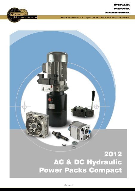
HydrauliekPneumatiekAandrijftechniekHEERHUGOWAARD . T: +31 (0)72 57 66 700 . WWW.TOTALHYDRAULICS<strong>BV</strong>.COM2012AC & DC HydraulicPower Packs CompactCompact 1
HydrauliekPneumatiekAandrijftechniekHEERHUGOWAARD . T: +31 (0)72 57 66 700 . WWW.TOTALHYDRAULICS<strong>BV</strong>.COMsales@hydronit.com · +39 0362 1841 210POWER PACKS COMPACT series ordering codewww.hydronit.comPPC2012/1-01Compact 2
HydrauliekPneumatiekAandrijftechniekHEERHUGOWAARD . T: +31 (0)72 57 66 700 . WWW.TOTALHYDRAULICS<strong>BV</strong>.COMsales@hydronit.com · +39 0362 1841 210QUICK SELECTION GUIDEAC & DC electric motorsDC motorsSection A0,15 12DC_T 12VDC motor - 150W - Ø 80 + thermal switch0,15 24DC_T 24VDC motor - 150W - Ø 80 + thermal switch0,5 12DC 12VDC motor - 500W - Ø 800,5 24DC 24VDC motor - 500W - Ø 800,5 12DC_T 12VDC motor - 500W - Ø 80 + thermal switch0,5 24DC_T 24VDC motor - 500W - Ø 80 + thermal switch0,8 12DC 12VDC motor - 800W - Ø 800,8 24DC 24VDC motor - 800W - Ø 800,8 12DC_T 12VDC motor - 800W - Ø 80 + thermal switch0,8 24DC_T 24VDC motor - 800W - Ø 80 + thermal switch1,6 12DC_T 12VDC motor - 1600W - Ø 114 + thermal switch2,1 12DC_T 12VDC motor - 2100W - Ø 114 + thermal switch2,2 24DC_T 24VDC motor - 2200W - Ø 114 + thermal switch2,4 12DC_T 12VDC motor - 2400W - Ø 125 fan cooled + thermal switch3 24DC_T 24VDC motor - 3000W - Ø 125 fan cooled + thermal switch2,5HD 12DC_T 12VDC motor - 2500W - Ø 151 fan cooled B14-90 frame + thermal switch3HD 24DC_T 24VDC motor - 3000W - Ø 151 fan cooled B14-90 frame + thermal switch4HD 24DC_T 24VDC motor - 4000W - Ø 151 fan cooled B14-90 frame + thermal switchAC motors: three-phase 4 poles (~1450 rpm @ 50Hz / ~1750 rpm @ 60Hz)E037AC341S3 integral motor 0,37kW S3 3-ph 4-pole 220/380V 50/60Hz frame 71E055AC341S3 integral motor 0,55kW S3 3-ph 4-pole 220/380V 50/60Hz frame 71E075AC342S3 integral motor 0,75kW S3 3-ph 4-pole 220/380V 50/60Hz frame 80E110AC342S3 integral motor 1,1kW S3 3-ph 4-pole 220/380V 50/60Hz frame 80E150AC343S3 integral motor 1,5kW S3 3-ph 4-pole 220/380V 50/60Hz frame 90E220AC343S3 integral motor 2,2kW S3 3-ph 4-pole 220/380V 50/60Hz frame 90E300AC343S3 integral motor 3kW S3 3-ph 4-pole 220/380V 50/60Hz frame 90AC motors: single-phase 4 poles (~1450 rpm at 50Hz)E037ACS41S3 integral motor 0,37kW S3 1-ph 4-pole 220V 50Hz frame 71E055ACS41S3 integral motor 0,55kW S3 1-ph 4-pole 220V 50Hz frame 71E075ACS42S3 integral motor 0,75kW S3 1-ph 4-pole 220V 50Hz frame 80E110ACS43S3 integral motor 1,1kW S3 1-ph 4-pole 220V 50Hz frame 90E150ACS43S3 integral motor 1,5kW S3 1-ph 4-pole 220V 50Hz frame 90E220ACS43S3 integral motor 2,2kW S3 1-ph 4-pole 220V 50Hz frame 902 pole and special execution motors (High starting torque, high IP, with thermal protector,...) available on requestwww.hydronit.comPPC2012/1-02Compact 3
HydrauliekPneumatiekAandrijftechniekHEERHUGOWAARD . T: +31 (0)72 57 66 700 . WWW.TOTALHYDRAULICS<strong>BV</strong>.COMsales@hydronit.com · +39 0362 1841 210QUICK SELECTION GUIDEAC & DC electric motorsB14 AC motorsB14550AC324S3 B14 motor 5,5kW S3 3-ph 2-pole 220/380V 50/60Hz frame 100B14750AC325S3 B14 motor 7,5kW S3 3-ph 2-pole 220/380V 50/60Hz frame 112B14400AC344S3 B14 motor 4kW S3 3-ph 4-pole 220/380V 50/60Hz frame 100B14550AC344S3 B14 motor 5,5kW S3 3-ph 4-pole 220/380V 50/60Hz frame 100B14750AC345S3 B14 motor 5,5kW S3 3-ph 4-pole 220/380V 50/60Hz frame 112B14300ACS44S3 B14 motor 3kW S3 1-ph 4-pole 220V 50Hz frame 100B14400ACS24S3 B14 motor 4kW S3 1-ph 2-pole 220V 50Hz frame 100No motor: B14 Flange + coupling kitXB14 71-0 mounting kit PPC for B14 motors frame 71 with pump group 0XB14 80-0 mounting kit PPC for B14 motors frame 80 with pump group 0XB14 71-1 mounting kit PPC for B14 motors frame 71 with pump group 1XB14 80-1 mounting kit PPC for B14 motors frame 80 with pump group 1XB14 90-1 mounting kit PPC for B14 motors frame 90 with pump group 1XB14 100-1 mounting kit PPC for B14 motors frame 100/112 with pump group 1X56C-0 mounting kit PPC for Nema 56C-face motors with pump group 0X56C-1 mounting kit PPC for Nema 56C-face motors with pump group 1Electric motors optionsDC motor optionsS150 12DC 80S150 24DC 80S150 12DC 112S150 24DC 112S200 12DCS200 24DCstarting relay 12VDC 150A with mounting kit for Ø 80 motorsstarting relay 24VDC 150A with mounting kit for Ø 80 motorsstarting relay 12VDC 150A with mounting kit for Ø 112-114 motorsstarting relay 24VDC 150A with mounting kit for Ø 112-114 motorsstarting relay 12VDC 200A for Ø 125 and Ø 151 motorsstarting relay 24VDC 200A for Ø 125 and Ø 151 motorsUniversal central manifoldInternational execution (1/4" BSP exit ports)Section BUAUBU4URUniversal A type PPC body with 3 lateral cavitiesUniversal B type PPC body with 5 lateral cavitiesUniversal 4 type PPC body for 4 way cartridge valvesUniversal R type PPC body for reversible pumpUSA execution (SAE 06 exit ports)UAUSUBUSU4USURUSUniversal A type PPC body with 3 lateral cavities US executionUniversal B type PPC body with 5 lateral cavities US executionUniversal 4 type PPC body for 4 way cartridge valves US executionUniversal R type PPC body for reversible pump US executionwww.hydronit.comPPC2012/1-03Compact 4
HydrauliekPneumatiekAandrijftechniekHEERHUGOWAARD . T: +31 (0)72 57 66 700 . WWW.TOTALHYDRAULICS<strong>BV</strong>.COMsales@hydronit.com · +39 0362 1841 210QUICK SELECTION GUIDEGear PumpsSection CG0,8 gear pump group 1 – 0,85 cc/rev G seriesG1,1 gear pump group 1 – 1,15 cc/rev G seriesG1,3 gear pump group 1 – 1,3 cc/rev G seriesG1,6 gear pump group 1 – 1,6 cc/rev G seriesG2,1 gear pump group 1 – 2,1 cc/rev G seriesG2,6 gear pump group 1 – 2,6 cc/rev G seriesG3,2 gear pump group 1 – 3,2 cc/rev G seriesG3,7 gear pump group 1 – 3,7 cc/rev G seriesG4,2 gear pump group 1 – 4,2 cc/rev G seriesG4,9 gear pump group 1 – 4,9 cc/rev G seriesG6,0 gear pump group 1 – 6,0 cc/rev G seriesG7,9 gear pump group 1 – 7,9 cc/rev G seriesG9,8 gear pump group 1 – 9,8 cc/rev G seriesG0,1 gear pump group 0 – 0,19 cc/rev K series + adaptor flange for group 0 pumpK0,2 gear pump group 0 – 0,26 cc/rev K series + adaptor flange for group 0 pumpK0,4 gear pump group 0 – 0,38 cc/rev K series + adaptor flange for group 0 pumpK0,6 gear pump group 0 – 0,64 cc/rev K series + adaptor flange for group 0 pumpK0,9 gear pump group 1 – 0,89 cc/rev K seriesK1,2 gear pump group 1 – 1,27 cc/rev K seriesK1,6 gear pump group 1 – 1,66 cc/rev K seriesK2,1 gear pump group 1 – 2,17 cc/rev K seriesK2,7 gear pump group 1 – 2,8 cc/rev K seriesK3,2 gear pump group 1 – 3,3 cc/rev K seriesK3,7 gear pump group 1 – 3,8 cc/rev K seriesK4,2 gear pump group 1 – 4,3 cc/rev K seriesK5,0 gear pump group 1 – 5,1 cc/rev K seriesK6,0 gear pump group 1 – 6,0 cc/rev K seriesK7,9 gear pump group 1 – 7,9 cc/rev K seriesH1,2 gear pump group 1 high pressure – 1,2 cc/rev H seriesH1,7 gear pump group 1 high pressure – 1,7 cc/rev H seriesH2,2 gear pump group 1 high pressure – 2,2 cc/rev H seriesH2,6 gear pump group 1 high pressure – 2,6 cc/rev H seriesH3,2 gear pump group 1 high pressure – 3,2 cc/rev H seriesH3,8 gear pump group 1 high pressure – 3,8 cc/rev H seriesH4,2 gear pump group 1 high pressure – 4,3 cc/rev H seriesH4,7 gear pump group 1 high pressure – 4,7 cc/rev H serieswww.hydronit.comPPC2012/1-04Compact 5
HydrauliekPneumatiekAandrijftechniekHEERHUGOWAARD . T: +31 (0)72 57 66 700 . WWW.TOTALHYDRAULICS<strong>BV</strong>.COMsales@hydronit.com · +39 0362 1841 210QUICK SELECTION GUIDEGear PumpsDouble gear pumps with Hi-Lo systemK0,9+3,2HLK1,2+5HLHI-LO double pump - 0,9 + 3,3cc/rev K seriesHI-LO double pump - 1,2 + 5cc/rev K seriesBidirectional gear pumpsR0,2 Reversible gear pump group 0-0,26 cc/rev + adaptor flange for group 0 pumpR0,4 reversible gear pump - 0,38cc/rev + adaptor flange for group 0 pumpR0,6 reversible gear pump - 0,63cc/rev + adaptor flange for group 0 pumpR0,9 reversible gear pump - 0,88cc/rev + adaptor flange for group 0 pumpR1,3 reversible gear pump - 1,25cc/rev + adaptor flange for group 0 pumpR1,5 reversible gear pump - 1,5cc/rev + adaptor flange for group 0 pumpR2,1 Reversible gear pump group 1 - 2,1 cc/revR2,6 Reversible gear pump group 1 - 2,6 cc/revHelical rotor pumps for high pressure and low noise and low pulsation applicationsS4,2 low noise helical rotor pump group 1 - 4,2cc/revS6,4 low noise helical rotor pump group 1 - 6,4cc/revS8,3 low noise helical rotor pump group 1 - 8,3cc/revS10low noise helical rotor pump group 1 - 10,2cc/revS13low noise helical rotor pump group 1 - 12,9cc/revIntegral components: Cavity 0Components in central manifold cavity 0Section DJSLNcheck valve ball type 3/4-16UNFflow control valve 3/4-16UNF with screwplug 3/4-16UNF basicplug 3/4-16UNF open passage with 1/4”BSPP exit portCavity 0 optionEP01exit port ¼ BSPPEM9001C pressure gauge shut-off valve 90° F-F + nipples M 1/4” BSPP – M 1/4” BSPPEMIL01C pressure gauge shut-off valve F-F + nipples M 1/4” BSPP – M 1/4” BSPPF401**J pressure switch 1/4” BSPP where ** = max setting pressure (050-100-200-400 bar)MIR63**EM pressure gauge Ø63 where ** = max press. (60-160-250-315 bar) + shut-off valve 90°Integral components: Cavity 1Components in central manifold cavity 1D_60D_180D_280D_350XPguided needle relief valve M20x1,5 - 10÷60 bar - socket screw adj.guided needle relief valve M20x1,5 - 20÷180 bar - socket screw adj.guided needle relief valve M20x1,5 - 35÷280 bar - socket screw adj.Guided needle relief valve M20x1,5 - 50÷350 bar - socket screw adj.closed plug for relief valve M20x1,5 cavitywww.hydronit.comPPC2012/1-05Compact 6
HydrauliekPneumatiekAandrijftechniekHEERHUGOWAARD . T: +31 (0)72 57 66 700 . WWW.TOTALHYDRAULICS<strong>BV</strong>.COMsales@hydronit.com · +39 0362 1841 210QUICK SELECTION GUIDECavity 1 option2 handwheel M8 for VMDC35/VMDC20/VCF6 valves3 steel cap for VMDC35 relief valve4 plastic seal for VMDC35 relief valveIntegral components: Cavity 2Components in central manifold cavity 2XABCDEEMZST12DCT24DCUGHNPLJ4VA11C4VA24VB24VC24VE2open cavity – no valveNC solenoid 2/2 way 3/4-16UNF poppet valveNC solenoid 2/2 way 3/4-16UNF poppet valve with emergencyNO solenoid 2/2 way 3/4-16UNF poppet valve with emergencyNC solenoid 2/2 way 3/4-16UNF double poppet valve with emergencylever operated 2/2 way valve without micro-switchlever operated 2/2 way valve with micro-switch2 way emergency button valveflow control valve 3/4-16UNF with screwproportional flow control valve poppet type 15l/min 315 bar + coil 12VDC ED100%proportional flow control valve poppet type 15l/min 315 bar + coil 24VDC ED100%hand pump 3/4-16UNF 2 cc/stroke + suction/return line pipe 1/4”BSP 370mmclosed plug 3/4-16UNFplug 3/4-16UNF with 1/4”BSPP exit portplug 3/4-16UNF open passage with 1/4”BSPP exit portplug 3/4-16UNF passing through 1/4”BSPPplug 3/4-16UNF basiccheck valve ball type 3/4-16UNF4/2 way solenoid directional valve, closed center transient (only for U4 manifolds)4/3 way solenoid directional valve, center P to T (only for U4 manifolds)4/3 way solenoid directional valve, closed center (only for U4 manifolds)4/3 way solenoid directional valve, H center (only for U4 manifolds)4/3 way solenoid directional valve, center A-B to T (only for U4 manifolds)Cavity 2 optionV-CSBhandwheel for CSB/CSUEM9001C pressure gauge shut-off valve 90° F-F + nipples M 1/4” BSPP – M 1/4” BSPPEMIL01C pressure gauge shut-off valve F-F + nipples M 1/4” BSPP – M 1/4” BSPPF401**pressure switch 1/4” BSPP where ** = max setting pressure (050-100-200-400 bar)MIR63**EM pressure gauge Ø63 where ** = max press. (60-160-250-315 bar) + shut-off valve 90°Cavity 2 valve coil12DC_M130 Coil 12V DC 18W ED75% for MSV30-31 + Electric connector DIN 43650-A24DC_M130 Coil 24V DC 18W ED75% for MSV30-31 + Electric connector DIN 43650-A24RAC_M130 Coil 24V DC 18W ED75% for MSV30-31 + El. connector with rectifier 12-24V115_50AC_M130 Coil 115V/50Hz AC 28VA ED75% only for MSV30 + El. connector DIN 43650-A230_50AC_M130 Coil 230V/50Hz AC 28VA ED75% only for MSV30 + El. connector DIN 43650-A110RAC_M130 Coil 110V RAC 18W ED75% for MSV30-31 + El. connector with rectifier 115 V220RAC_M130 Coil 220V RAC 18W ED75% for MSV30-31 + El. connector with rectifier 230 Vwww.hydronit.comPPC2012/1-06Compact 7
HydrauliekPneumatiekAandrijftechniekHEERHUGOWAARD . T: +31 (0)72 57 66 700 . WWW.TOTALHYDRAULICS<strong>BV</strong>.COMsales@hydronit.com · +39 0362 1841 210QUICK SELECTION GUIDECavity 2 valve coil12DC_M140 Coil 12V DC 22W ED100% for MSV-MDV + Electric connector DIN 43650-A24DC_M140 Coil 24V DC 22W ED100% for MSV-MDV + Electric connector DIN 43650-A24RAC_M140 Coil 24V DC 22W ED100% for MSV-MDV + El. connector with rectifier 12-24 V110RAC_M140 Coil 110V RAC 22W ED100% for MSV-MDV + El. connector with rectifier 115 V220RAC_M140 Coil 220V RAC 22W ED100% for MSV-MDV + El. connector with rectifier 230 V12DC_M630 coil 12V DC ED100% + Electric connector DIN 43650-A24DC_M630 coil 24V DC ED100% + Electric connector DIN 43650-A24AC_M631 coil 24V AC ED100% with integrated rectifier + Electric connector DIN 43650-A115AC_M631 coil 115V AC ED100% with integrated rectifier + Electric connector DIN 43650-A230AC_M631 coil 230V AC ED100% with integrated rectifier + Electric connector DIN 43650-AIntegral components: Cavity 3Components in central manifold cavity 3F02F03F04F05F06F07F09F11F13F15R2R3R4R5R6R7SZARBRCRDJGHNPLP**12DCP**24DCV**fixed pressure compensated flow control valve 3/4-16UNF hole 0,8mmfixed pressure compensated flow control valve 3/4-16UNF hole 1mmfixed pressure compensated flow control valve 3/4-16UNF hole 1,25mmfixed pressure compensated flow control valve 3/4-16UNF hole 1,5mmfixed pressure compensated flow control valve 3/4-16UNF hole 1,75mmfixed pressure compensated flow control valve 3/4-16UNF hole 2mmfixed pressure compensated flow control valve 3/4-16UNF hole 2,5mmfixed pressure compensated flow control valve 3/4-16UNF hole 3mmfixed pressure compensated flow control valve 3/4-16UNF hole 3,5mmfixed pressure compensated flow control valve 3/4-16UNF hole 4mmcompensated flow control valve 3/4-16UNF with screw 1 ÷ 2,2 l/mincompensated flow control valve 3/4-16UNF with screw 1,6 ÷ 4 l/mincompensated flow control valve 3/4-16UNF with screw 2,5 ÷ 5 l/mincompensated flow control valve 3/4-16UNF with screw 3÷ 7 l/mincompensated flow control valve 3/4-16UNF with screw 4,9 ÷ 10,8 l/mincompensated flow control valve 3/4-16UNF with screw 8 ÷ 18,5 l/minflow control valve 3/4-16UNF with screw2 way emergency button valveNC solenoid 2/2 way 3/4-16UNF poppet valve with reversible flowNC solenoid 2/2 way 3/4-16UNF poppet valve +emergency with reversible flowNO solenoid 2/2 way 3/4-16UNF poppet valve + emergency with reversible flowNC solenoid 2/2 way 3/4-16UNF double poppet valve with emergencycheck valve ball type 3/4-16UNFclosed plug 3/4-16UNFplug 3/4-16UNF with 1/4”BSPP exit portplug 3/4-16UNF open passage with 1/4”BSPP exit portplug 3/4-16UNF passing through 1/4”BSPPplug 3/4-16UNF basicproportional relief valve 3/4-16UNF 12VDC where ** = max pressure (60-210 bar)proportional relief valve 3/4-16UNF 24VDC where ** = max pressure (60-210 bar)relief valve 3/4-16UNF where ** = max pressure (40-110-250-350 bar) - socket screwwww.hydronit.comPPC2012/1-07Compact 8
HydrauliekPneumatiekAandrijftechniekHEERHUGOWAARD . T: +31 (0)72 57 66 700 . WWW.TOTALHYDRAULICS<strong>BV</strong>.COMsales@hydronit.com · +39 0362 1841 210QUICK SELECTION GUIDECavity 3 optionV-CSBhandwheel for CSB/CSU2 handwheel M8 for VMDC35/VMDC20/VCF6 valvesEM9001C pressure gauge shut-off valve 90° F-F + nipples M 1/4” BSPP – M 1/4” BSPPEMIL01C pressure gauge shut-off valve F-F + nipples M 1/4” BSPP – M 1/4” BSPPF401**pressure switch 1/4” BSPP where ** = max setting pressure (050-100-200-400 bar)MIR63**EM pressure gauge Ø63 where ** = max press. (60-160-250-315 bar) + shut-off valve 90°Cavity 3 valve coil voltage12DC_M130 Coil 12V DC 18W ED75% for MSV30-31 + Electric connector DIN 43650-A24DC_M130 Coil 24V DC 18W ED75% for MSV30-31 + Electric connector DIN 43650-A24RAC_M130 Coil 24V DC 18W ED75% for MSV30-31 + El. connector with rectifier 12-24 V115_50AC_M130 Coil 115V/50Hz AC 28VA ED75% only for MSV30 + Electric connector DIN 43650-A230_50AC_M130 Coil 230V/50Hz AC 28VA ED75% only for MSV30 + Electric connector DIN 43650-A110RAC_M130 Coil 110V RAC 18W ED75% for MSV30-31 + El. connector with rectifier 115 V220RAC_M130 Coil 220V RAC 18W ED75% for MSV30-31 + El. connector with rectifier 230 V12DC_M140 Coil 12V DC 22W ED100% for MSV-MDV + Electric connector DIN 43650-A24DC_M140 Coil 24V DC 22W ED100% for MSV-MDV + Electric connector DIN 43650-A24RAC_M140 Coil 24V DC 22W ED100% for MSV-MDV + El. connector with rectifier 12-24 V110RAC_M140 Coil 110V RAC 22W ED100% for MSV-MDV + El. connector with rectifier 115 V220RAC_M140 Coil 220V RAC 22W ED100% for MSV-MDV + El. connector with rectifier 230 VIntegral components: Cavity 4Component in central manifold cavity 4ABCDEEMZST12DCT24DCUGHNPLJNC solenoid 2/2 way 3/4-16UNF poppet valveNC solenoid 2/2 way 3/4-16UNF poppet valve with emergencyNO solenoid 2/2 way 3/4-16UNF poppet valve with emergencyNC solenoid 2/2 way 3/4-16UNF double poppet valve with emergencylever operated 2/2 way valve without micro-switchlever operated 2/2 way valve with micro-switch2 way emergency button valveflow control valve 3/4-16UNF with screwproportional flow control valve poppet type 15l/min 315 bar + coil 12VDC ED100%proportional flow control valve poppet type 15l/min 315 bar + coil 24VDC ED100%hand pump 3/4-16UNF 2 cc/stroke + suction/return line pipe 1/4”BSP 370mmclosed plug 3/4-16UNFplug 3/4-16UNF with 1/4”BSPP exit portplug 3/4-16UNF open passage with 1/4”BSPP exit portplug 3/4-16UNF passing through 1/4”BSPPplug 3/4-16UNF basiccheck valve ball type 3/4-16UNFwww.hydronit.comPPC2012/1-08Compact 9
HydrauliekPneumatiekAandrijftechniekHEERHUGOWAARD . T: +31 (0)72 57 66 700 . WWW.TOTALHYDRAULICS<strong>BV</strong>.COMsales@hydronit.com · +39 0362 1841 210QUICK SELECTION GUIDECavity 4 optionV-CSBhandwheel for CSB/CSUEM9001C pressure gauge shut-off valve 90° F-F + nipples M 1/4” BSPP – M 1/4” BSPPEMIL01C pressure gauge shut-off valve F-F + nipples M 1/4” BSPP – M 1/4” BSPPF401**pressure switch 1/4” BSPP where ** = max setting pressure (050-100-200-400 bar)MIR63**EM pressure gauge Ø63 where ** = max press. (60-160-250-315 bar) + shut-off valve 90°Cavity 4 valve coil voltage12DC_M130 Coil 12V DC 18W ED75% for MSV30-31 + Electric connector DIN 43650-A24DC_M130 Coil 24V DC 18W ED75% for MSV30-31 + Electric connector DIN 43650-A24RAC_M130 Coil 24V DC 18W ED75% for MSV30-31 + El. connector with rectifier 12-24 V115_50AC_M130 Coil 115V/50Hz AC 28VA ED75% only for MSV30 + Electric connector DIN 43650-A230_50AC_M130 Coil 230V/50Hz AC 28VA ED75% only for MSV30 + Electric connector DIN 43650-A110RAC_M130 Coil 110V RAC 18W ED75% for MSV30-31 + El. connector with rectifier 115 V220RAC_M130 Coil 220V RAC 18W ED75% for MSV30-31 + El. connector with rectifier 230 V12DC_M140 Coil 12V DC 22W ED100% for MSV-MDV + Electric connector DIN 43650-A24DC_M140 Coil 24V DC 22W ED100% for MSV-MDV + Electric connector DIN 43650-A24RAC_M140 Coil 24V DC 22W ED100% for MSV-MDV + El. connector with rectifier 12-24 V110RAC_M140 Coil 110V RAC 22W ED100% for MSV-MDV + El. connector with rectifier 115 V220RAC_M140 Coil 220V RAC 22W ED100% for MSV-MDV + El. connector with rectifier 230 VFlow restrictor in central manifold cavity 5Flow restrictor in central manifold cavity 5PLUGTCE01PP013701/4” BSPP plug with copper washersuction/return line pipe 1/4”BSP 370mmRETURN-KIT 1/4” BSP holder for SF12 + flexible plastic pipe 12 mm for return line / price per meterC34200001 return line tank immersed filter1(01) fixed pressure compensated flow control valve 1/4"BSP 1l/min2(01) fixed pressure compensated flow control valve 1/4"BSP 2l/min3(01) fixed pressure compensated flow control valve 1/4"BSP 3l/min4(01) fixed pressure compensated flow control valve 1/4"BSP 4l/min5(01) fixed pressure compensated flow control valve 1/4"BSP 5l/min6(01) fixed pressure compensated flow control valve 1/4"BSP 6l/min8(01) fixed pressure compensated flow control valve 1/4"BSP 8l/min10(01) fixed pressure compensated flow control valve 1/4"BSP 10l/min12(01) fixed pressure compensated flow control valve 1/4"BSP 12l/min15(01) fixed pressure compensated flow control valve 1/4"BSP 15l/minwww.hydronit.comPPC2012/1-09Compact 10
HydrauliekPneumatiekAandrijftechniekHEERHUGOWAARD . T: +31 (0)72 57 66 700 . WWW.TOTALHYDRAULICS<strong>BV</strong>.COMsales@hydronit.com · +39 0362 1841 210QUICK SELECTION GUIDEFlow restrictor in central manifold cavity 6Flow restrictor in central manifold cavity 6PLUGTCE01PP013701/4” BSPP plug with copper washersuction/return line pipe 1/4”BSP 370mmRETURN-KIT 1/4” BSP holder for SF12 + flexible plastic pipe 12 mm for return line / price per meterC34200001 return line tank immersed filter1(01) fixed pressure compensated flow control valve 1/4"BSP 1l/min2(01) fixed pressure compensated flow control valve 1/4"BSP 2l/min3(01) fixed pressure compensated flow control valve 1/4"BSP 3l/min4(01) fixed pressure compensated flow control valve 1/4"BSP 4l/min5(01) fixed pressure compensated flow control valve 1/4"BSP 5l/min6(01) fixed pressure compensated flow control valve 1/4"BSP 6l/min8(01) fixed pressure compensated flow control valve 1/4"BSP 8l/min10(01) fixed pressure compensated flow control valve 1/4"BSP 10l/min12(01) fixed pressure compensated flow control valve 1/4"BSP 12l/min15(01) fixed pressure compensated flow control valve 1/4"BSP 15l/minFlow restrictor in central manifold cavity 7Flow restrictor in central manifold cavity 70(04) closed plug Ø 12,7 with o-ring1(04) fixed pressure compensated flow control valve Ø 12,7 with o-ring 1l/min2(04) fixed pressure compensated flow control valve Ø 12,7 with o-ring 2l/min3(04) fixed pressure compensated flow control valve Ø 12,7 with o-ring 3l/min4(04) fixed pressure compensated flow control valve Ø 12,7 with o-ring 4l/min5(04) fixed pressure compensated flow control valve Ø 12,7 with o-ring 5l/min6(04) fixed pressure compensated flow control valve Ø 12,7 with o-ring 6l/min8(04) fixed pressure compensated flow control valve Ø 12,7 with o-ring 8l/min10(04) fixed pressure compensated flow control valve Ø 12,7 with o-ring 10l/min12(04) fixed pressure compensated flow control valve Ø 12,7 with o-ring 12l/min15(04) fixed pressure compensated flow control valve Ø 12,7 with o-ring 15l/minFlow restrictor in central manifold cavity 8Flow restrictor in central manifold cavity 8PLUGTCE01PP013701/4” BSPP plug with copper washersuction/return line pipe 1/4”BSP 370mmRETURN-KIT 1/4” BSP holder for SF12 + flexible plastic pipe 12 mm for return line / price per meterC34200001 return line tank immersed filter1(01) fixed pressure compensated flow control valve 1/4"BSP 1l/min2(01) fixed pressure compensated flow control valve 1/4"BSP 2l/min3(01) fixed pressure compensated flow control valve 1/4"BSP 3l/min4(01) fixed pressure compensated flow control valve 1/4"BSP 4l/min5(01) fixed pressure compensated flow control valve 1/4"BSP 5l/min6(01) fixed pressure compensated flow control valve 1/4"BSP 6l/min8(01) fixed pressure compensated flow control valve 1/4"BSP 8l/min10(01) fixed pressure compensated flow control valve 1/4"BSP 10l/min12(01) fixed pressure compensated flow control valve 1/4"BSP 12l/min15(01) fixed pressure compensated flow control valve 1/4"BSP 15l/minwww.hydronit.comPPC2012/1-10Compact 11
HydrauliekPneumatiekAandrijftechniekHEERHUGOWAARD . T: +31 (0)72 57 66 700 . WWW.TOTALHYDRAULICS<strong>BV</strong>.COMsales@hydronit.com · +39 0362 1841 210QUICK SELECTION GUIDETanksSteel tanksSection E1,5A 1,5l cylindrical steel tank horizontal mounting + 1/2"BSPP std filler & breather plug1,5AV1,5l cylindrical steel tank vertical mounting + 1/2"BSPP std filler & breather plug2,5A 2,5l cylindrical steel tank horizontal mounting + 1/2"BSPP std filler & breather plug2,5AV2,5l cylindrical steel tank vertical mounting + 1/2"BSPP std filler & breather plug5B5l cylindrical steel tank horizontal mounting + 1/2"BSPP std filler & breather plug5<strong>BV</strong>5l cylindrical steel tank vertical mounting + 1/2"BSPP std filler & breather plug10B10l cylindrical steel tank horizontal mounting + 1/2"BSPP std filler & breather plug10<strong>BV</strong>10l cylindrical steel tank vertical mounting + 1/2"BSPP std filler & breather plug12B12l cylindrical steel tank horizontal mounting + 1/2"BSPP std filler & breather plug12<strong>BV</strong>12l cylindrical steel tank vertical mounting + 1/2"BSPP std filler & breather plug10C10l square steel tank horizontal mounting + 1/2"BSPP std filler & breather plug10CV10l square steel tank vertical mounting + 1/2"BSPP std filler & breather plug22C22l square steel tank horizontal mounting + ¾"BSPP male filler & breather plug22CV22l square steel tank vertical mounting + ¾"BSPP male filler & breather plug3EV3l vertical square steel tank vertical mounting + 1/2"BSPP std filler & breather plug7EV7l vertical square steel tank vertical mounting + 1/2"BSPP std filler & breather plug8EV8l vertical square steel tank vertical mounting + ¾"BSPP male filler & breather plug15EV15l vertical square steel tank vertical mounting + ¾"BSPP male filler & breather plug20EV20l vertical square steel tank vertical mounting + ¾"BSPP male filler & breather plug30EV30l vertical square steel tank vertical mounting + ¾"BSPP male filler & breather plugF80000001 steel tank adapter for PPC - to be welded on custom made tanksPlastic tanks1,5L 1,5l square plastic tank type L horizontal mounting + 3/4”BSPP F filler & breather plug1,5LV1,5l square plastic tank type L vertical mounting + 3/4”BSPP F filler & breather plug3L3l square plastic tank type L horizontal mounting + 3/4”BSPP F filler & breather plug3LV3l square plastic tank type L vertical mounting + 3/4”BSPP F filler & breather plug6L6l square plastic tank type L horizontal mounting + 3/4”BSPP F filler & breather plug6LV6l square plastic tank type L vertical mounting + 3/4”BSPP F filler & breather plug5M5l square plastic tank 170mm type M horizontal mounting + 3/4”BSPP F filler & breather5MV5l square plastic tank 170mm type M vertical mounting + 3/4”BSPP F filler & breather8M8l square plastic tank 170mm type M horizontal mounting + 3/4”BSPP F filler & breather8MV8l square plastic tank 170mm type M vertical mounting + 3/4”BSPP F filler & breather5P5l round plastic tank for PPC Ø195mm horizontal mounting + 1/2"BSPP filler & breather5PV5l round plastic tank for PPC Ø195mm vertical mounting + 1/2"BSPP filler & breather9P9l round plastic tank for PPC Ø195mm horizontal mounting + 1/2"BSPP filler & breather9PV9l round plastic tank for PPC Ø195mm vertical mounting + 1/2"BSPP filler & breather12N12l square plastic tank 180mm type N horizontal mounting + 1/2"BSPP filler & breather12NV12l square plastic tank 180mm type N vertical mounting + 1/2"BSPP filler & breatherwww.hydronit.comPPC2012/1-11Compact 12
HydrauliekPneumatiekAandrijftechniekHEERHUGOWAARD . T: +31 (0)72 57 66 700 . WWW.TOTALHYDRAULICS<strong>BV</strong>.COMsales@hydronit.com · +39 0362 1841 210QUICK SELECTION GUIDEAccessoriesAccessoriesE60543006E60543007MIR63**EM9001CEMIL01CF16000001F401**F4R0M3MIR4010P0201P0202VPC00BFCSAE0801BFCSAE0802foot mounting support 45mmfoot mounting support tall type (67mm)pressure gauge Ø63 where ** = max press. (60-160-250-315 bar)pressure gauge shut-off valve 90° F-F + nipples M 1/4” BSPP – M 1/4” BSPPpressure gauge shut-off valve F-F + nipples M 1/4” BSPP – M 1/4” BSPPplastic Ø112-114 DC motor protection coverpressure switch 1/4” BSPP where ** = max setting pressure (050-100-200-400 bar)pressure switch 1/8” BSPP 0,2-2,5bar for filter manifold E60403020pressure gauge Ø40 10bar max for filter manifold E60403020remote up/down control with 3m flying cable for single/double acting cylinderremote 4 buttons control with 3m flying cable for 2 double acting cylinderselectronic PWM driver for proportional valves 12/24VDCin-line manifolds for 3/4-16UNF valves 1/4” BSPP portsin-line manifolds for 3/4-16UNF valves 3/8” BSPP portsExternal manifoldsSection FExternal manifoldsE60403004E60403005E60403002E60403001E60403010E60403011E60413002E60413001E60413003E60403027E60403028E60403020PM09E60403006E60403008MM60403010M60403004M60403005M60413002M60413001M60413003E60403030E6040303128mm spacer subplatePPC 90° rotation manifold 79 mmPPC 90° rotation manifold 49 mmNG6 (cetop 3) parallel block - 3/8” BSPP rear ports (9/16-18UNF for US)NG6 (cetop 3) parallel block - 3/8” BSPP lateral ports (9/16-18UNF for US)NG6 (cetop 3) series block - 3/8” BSPP lateral ports (9/16-18UNF for US)NG6 (cetop 3) manifold with piloted check valve on ANG6 (cetop 3) manifold with piloted check valve on A and BNG6 (cetop 3) manifold with piloted check valve on Bmodular manifold with piloted check valves on A and Bmodular manifold with check valve for differential area cylindermodular basic manifold for spin-on return filter on T linehand pump 8,8 cc/stroke – cartridge only + base modular manifoldPPC to SD01 converter (needed to mount SD01 stackable valves)PPC to PPM base converter (needed to mount SD00 NG3 MICRO valves)PPM NG3 MICRO modular manifold with 1/4" BSPP lateral ports (9/16-18UNF for US)PPM spacer elementPPM 90° rotation manifoldPPM NG3 MICRO modular manifold with piloted check valves on APPM NG3 MICRO modular manifold with piloted check valves on A and BPPM NG3 MICRO modular manifold with piloted check valves on Bmanifold for MSV or MDV 2/2 way cartridge valvesmanifold for MSV3V 3/2 way cartridge valvewww.hydronit.comPPC2012/1-12Compact 13
HydrauliekPneumatiekAandrijftechniekHEERHUGOWAARD . T: +31 (0)72 57 66 700 . WWW.TOTALHYDRAULICS<strong>BV</strong>.COMsales@hydronit.com · +39 0362 1841 210QUICK SELECTION GUIDEExternal valvesSection GExternal valvesMSV3V4000000MSV3000000MSV30E0000MSV31E0000MDV30E0000SD00A11C3/2 way solenoid cartridge valve, A to T de-energizedNC solenoid 2/2 way 3/4-16UNF poppet valveNC solenoid 2/2 way 3/4-16UNF poppet valve with emergencyNO solenoid 2/2 way 3/4-16UNF poppet valve with emergencyNC solenoid 2/2 way 3/4-16UNF double poppet valve with emergencyNG3 MICRO solenoid directional valve 4 way, 2 positionsSD00A2 NG3 MICRO solenoid directional valve 4 way, 3 pos. center P to TSD00B2 NG3 MICRO solenoid directional valve 4 way, 3 pos. closed centerSD00C2 NG3 MICRO solenoid directional valve 4 way, 3 pos. H centerSD00E2 NG3 MICRO solenoid directional valve 4 way, 3 pos. center A-B to TSD01A11C Stackable solenoid directional valve 4 way, 2 positionsSD01A2 Stackable solenoid directional valve 4 way, 3 pos. center P to TSD01B2 Stackable solenoid directional valve 4 way, 3 pos. closed centerSD01C2 Stackable solenoid directional valve 4 way, 3 pos. H centerSD01E2 Stackable solenoid directional valve 4 way, 3 pos. center A-B to TSD01A11CC Stackable solenoid directional valve 4 way, 2 positions, stack top closedSD01A2C Stackable solenoid directional valve 4 way, 3 pos. center P to T, stack top closedSD01B2C Stackable solenoid directional valve 4 way, 3 pos. closed center, stack top closedSD01C2C Stackable solenoid directional valve 4 way, 3 pos. H center, stack top closedSD01E2C Stackable solenoid directional valve 4 way, 3 pos. center A-B to T, stack top closedSD03A11C NG6 (cetop3) solenoid directional valve 4 way, 2 positionsSD03A2 NG6 (cetop3) solenoid directional valve 4 way, 3 pos. center P to TSD03B2 NG6 (cetop3) solenoid directional valve 4 way, 3 pos. closed centerSD03C2 NG6 (cetop3) solenoid directional valve 4 way, 3 pos. H centerSD03E2 NG6 (cetop3) solenoid directional valve 4 way, 3 pos. center A-B to THD03A1 NG6 (cetop3) manual directional valve, spring centered P to THD03A2 NG6 (cetop3) manual directional valve, spring centered closed centerHD03A3 NG6 (cetop3) manual directional valve, spring centered H centerHD03A10 NG6 (cetop3) manual directional valve, spring centered A-B to THD03D1 NG6 (cetop3) manual directional valve, detent, center P to THD03D2 NG6 (cetop3) manual directional valve, detent, closed centerHD03D3 NG6 (cetop3) manual directional valve, detent, H centerHD03D10 NG6 (cetop3) manual directional valve, detent, center A-B to TE60423001LE60423001AE60423001BE60423002LE60423002AE60423002BE60423003LE60423003AE60423003BE60433000E60433001E60433002E60433003www.hydronit.comNG6 (cetop3) sandwich type modular valve with relief valve on A & B 60bar maxNG6 (cetop3) sandwich type modular valve with relief valve on A & B 180bar maxNG6 (cetop3) sandwich type modular valve with relief valve on A & B 280bar maxNG6 (cetop3) sandwich type modular valve with relief valve on A 60bar maxNG6 (cetop3) sandwich type modular valve with relief valve on A 180bar maxNG6 (cetop3) sandwich type modular valve with relief valve on A 280bar maxNG6 (cetop3) sandwich type modular valve with relief valve on B 60bar maxNG6 (cetop3) sandwich type modular valve with relief valve on B 180bar maxNG6 (cetop3) sandwich type modular valve with relief valve on B 280bar maxNG6 (cetop3) sandwich type modular valve for unidirectional throttle valveNG6 (cetop3) sandwich type modular valve with unidirectional throttle valve on A & BNG6 (cetop3) sandwich type modular valve with unidirectional throttle valve on ANG6 (cetop3) sandwich type modular valve with unidirectional throttle valve on BPPC2012/1-13Compact 14
HydrauliekPneumatiekAandrijftechniekHEERHUGOWAARD . T: +31 (0)72 57 66 700 . WWW.TOTALHYDRAULICS<strong>BV</strong>.COMsales@hydronit.com · +39 0362 1841 210QUICK SELECTION GUIDEExternal cartridge valves coils12DC_M130 Coil 12V DC 18W ED75% for MSV30-31 + Electric connector DIN 43650-A24DC_M130 Coil 24V DC 18W ED75% for MSV30-31 + Electric connector DIN 43650-A24RAC_M130 Coil 24V DC 18W ED75% for MSV30-31 + El. connector with rectifier 12-24 V115_50AC_M130 Coil 115V/50Hz AC 28VA ED75% only for MSV30 + Electric connector DIN 43650-A230_50AC_M130 Coil 230V/50Hz AC 28VA ED75% only for MSV30 + Electric connector DIN 43650-A110RAC_M130 Coil 110V RAC 18W ED75% for MSV30-31 + El. connector with rectifier 115 V220RAC_M130 Coil 220V RAC 18W ED75% for MSV30-31 + El. connector with rectifier 230 V12DC_M140 Coil 12V DC 22W ED100% for MSV-MDV + Electric connector DIN 43650-A24DC_M140 Coil 24V DC 22W ED100% for MSV-MDV + Electric connector DIN 43650-A24RAC_M140 Coil 24V DC 22W ED100% for MSV-MDV + El. connector with rectifier 12-24 V110RAC_M140 Coil 110V RAC 22W ED100% for MSV-MDV + El. connector with rectifier 115 V220RAC_M140 Coil 220V RAC 22W ED100% for MSV-MDV + El. connector with rectifier 230 VExternal SD00 valves coils12DC_M100 coil 12V DC 16W ED100% + Electric connector DIN 43650-A24DC_M100 coil 24V DC 16W ED100% + Electric connector DIN 43650-AExternal SD01 valves coils12DC_M120 coil 12V DC 22W ED100% + Electric connector DIN 43650-A24DC_M120 coil 24V DC 22W ED100% + Electric connector DIN 43650-A24RAC_M120 coil 24V DC 22W ED100% + El. conn. with rectifier 12-24 V black pg11220RAC_M120 coil 220V RAC 26W ED100% + El. conn. with rectifier 230 V black pg11External SD03 valves coils12DC_M160 coil 12V DC 26W ED100% + Electric connector DIN 43650-A24DC_M160 coil 24V DC 26W ED100% + Electric connector DIN 43650-A24RAC_M160 coil 24V DC 26W ED100% + El. conn. DIN 43650-A with rectifier 12-24 V black pg11110RAC_M160 coil 110V RAC 26W ED100% + El. conn. DIN 43650-A with rectifier 115 V black pg11220RAC_M160 coil 220V RAC 26W ED100% + El. conn. DIN 43650-A with rectifier 230 V black pg11www.hydronit.comPPC2012/1-14Compact 15
HydrauliekPneumatiekAandrijftechniekHEERHUGOWAARD . T: +31 (0)72 57 66 700 . WWW.TOTALHYDRAULICS<strong>BV</strong>.COMsales@hydronit.com · +39 0362 1841 210SECTION AAC & DC ELECTRIC MOTORSIntegral AC motors: the engineered solution for compact and optimised power units from 0,25 to 4 kW, single or threephase, 4 or 2 poles. These AC motors are directly flanged on the central manifold for extra compactness. A single tangdrive coupling can suit all frame sizes and powers.We suggest to adopt these advanced motors because of their peculiar advantages over standard B14 AC motors andbecause they are designed specifically for our mini power packs, offering an higher power density and high startingtorque (in HT models) than market standard motors. These motors are intended for intermittent duty (S3 40%), which isthe case for most mini-power packs applications. They can be used in emergency situations continuously at a reducedrated power (30% less than S3 nominal power).Single phase motors, due to their peculiar construction, should not run without load for long time to avoid overheating.B14 IEC standard AC motors: the standard solution easilyavailable on every market from 0,25 to 7,5 kW, single or threephase. These motors are normally procured by the customeritself. Hydronit provides adaptor flanges and double piececoupling for frame sizes: 71, 80, 90, 100 and 112.Frame 151 DC motors: real heavy duty bulkmotors, with fan cooling, thermal protectorand running time up to 16 min or over. Powerfrom 2,5kW 12VDC up to 4kW 24VDC.Frame 114 DC motors: the most popular choice. Power up to2,1kW 12VDC and 2,2kW 24VDC. All motors have thermalprotector switch as standard.Are AC motors compliant with the European Union Minimum Energy Performance Standards?Hydronit AC motors are manufactured in Italy with the best technologies nowadays available and are specifically designed for minipower packs duties, which are typically intermittent. Hydronit motors have an higher power density, lower weight, lower cost,comparing to standard IE2/IE3 motors on the market. Due to the specific field of applications, Hydronit motors are not included in therequirements of the above mentioned normative, since they are specially and solely manufactured for mini power packs intermittentduties. For continuous duty applications IE2 motors (IEC 60034-30) must be applied. Ask our sales office.Are there special requirements to mount IEC B14 motors?No special toolings are required. Please strictly follow motor side coupling mounting dimension tolerance as per the relevant drawings.Failing in doing so may cause malfunctioning of the power pack and even the break of the coupling and pump.Can I start single phase AC motors under load?Single phase motors have a reduced starting torque due to their intrinsecal design. Starting torque ranges around 30-40% of thenominal torque at full power output. When designing circuits where a single phase motor must start under load, a proper dimensioningmust be done and test on field must be preliminary performed. High starting torque «HT» motors are available. Ask our technical office.How do I dimension a DC motor?DC motors are normally for intermittent duty. It is important to know required flow in l/min, working pressure in bar and the dutycharge. Then, following A060 table instructions, a proper motor/pump combination can be selected.www.hydronit.comPPC2012/1-A000Compact 16
HydrauliekPneumatiekAandrijftechniekHEERHUGOWAARD . T: +31 (0)72 57 66 700 . WWW.TOTALHYDRAULICS<strong>BV</strong>.COMsales@hydronit.com · +39 0362 1841 210SECTION AINTEGRAL DC MOTORS Ø 80Starting switch option25,510,5Ø 7Permanent magnetsProtection degree: IP54Insulation class: FCodeThermal protection option2,5 L19Weight 500W/800W: 2,6 kg (without starter)Weight 150W: 2 kg (without starter)89,5RotationDescriptionPPC assemblycodeSpare part codeNominalduty cycleNominalspeedNominalcurrentL150W 12V DC + thermal protector 0,15 12DC/T M46C1ST01150W 24V DC + thermal protector 0,15 24DC/T M46C2ST01500W 12V DC motor 0,5 12DC M46C1S005500W 24V DC motor 0,5 24DC M46C2S005500W 12V DC + thermal protector 0,5 12DC/T M46C1ST05500W 24V DC + thermal protector 0,5 24DC/T M46C2ST05800W 12V DC motor 0,8 12DC M46C1S008800W 24V DC motor 0,8 24DC M46C2S008800W 12V DC + thermal protector 0,8 12DC/T M46C1ST08800W 24V DC + thermal protector 0,8 24DC/T M46C2ST08Options & couplingsS2:25 minS3: 50% EDS2: 25 minS3: 50% EDS2: 5 minS3: 17% EDS2: 5 minS3: 17% EDS2: 5 minS3: 17% EDS2: 5 minS3: 17% EDS2: 4 minS3: 10% EDS2: 4 minS3: 10% EDS2: 4 minS3: 10% EDS2: 4 minS3: 10% ED1400 rpm 30 A 108 mm1400 rpm 15 A 108 mm1700 rpm 90 A 139 mm2300 rpm 45 A 139 mm1700 rpm 90 A 139 mm2300 rpm 45 A 139 mm2100 rpm 150 A 139 mm2400 rpm 75 A 139 mm2100 rpm 150 A 139 mm2400 rpm 75 A 139 mmDescription PPC assembly code Spare part codeNotes: the starting12V DC 150 Amp start switch + mounting kit S150 12DC 80 M47SC0001 + M47SK0801switch mounting kit is24V DC 150 Amp start switch + mounting kit S150 24DC 80 M47SC0002 + M47SK0801 provided whenspecifying the /S150 asRemote wired control with 2 buttons and 3m cableP0201 (single acting)motor option in PPCassembly code.Remote wired control with 4 buttons and 3m cableP0202 (double acting)When ordering sparestarting switches, it mustCoupling for Ø 80 DC motors and gr.1 pumpE36200002be ordered separately(code: M47SK0801).Coupling for Ø 80 DC motors and gr.0 pumpE36200006E362000023776,4Weight: 0,041 kgE3620000643,352,856,4Weight: 0,063 kgThe coupling is alreadyincluded whenspecifying the motor inPPC assembly code.It is to be indicated onlywhen ordering PPC withno motor but withcoupling.www.hydronit.comPPC2012/1-A010Compact 17
HydrauliekPneumatiekAandrijftechniekHEERHUGOWAARD . T: +31 (0)72 57 66 700 . WWW.TOTALHYDRAULICS<strong>BV</strong>.COMsales@hydronit.com · +39 0362 1841 210SECTION AINTEGRAL DC MOTORS Ø 114Starting switch option12Compound woundProtection degree: IP54Insulation class: FWeight: 7,05 kg (without starter)16290±0.2RotationCode5,73,5DescriptionPPC assemblycodeSpare part codeNominalduty cycleNominalspeedNominalcurrent1600W 12V DC + thermal protector 1,6 12DC/T M46C1ST162100W 12V DC + thermal protector 2,1 12DC/T M46C1ST212200W 24V DC + thermal protector 2,2 24DC/T M46C2ST22Options & couplingsS2: 5 minS3: 10% EDS2: 4 minS3: 12% EDS2: 2.5 minS3: 10% ED2800 rpm 210 A2400 rpm 300 A2400 rpm 130 ADescription PPC assembly code Spare part code12V DC 150 Amp start switch + mounting kit S150 12DC 112 M47SC0001 + M47SK112124V DC 150 Amp start switch + mounting kit S150 24DC 112 M47SC0002 + M47SK1121Remote wired control with 2 buttons and 3m cableP0201 (single acting)Remote wired control with 4 buttons and 3m cableP0202 (double acting)DC motor plastic coverF16000001Coupling for Ø114 motors - Ø125 DC motors and gr.1 pumpE36200001Coupling for Ø114 motors and gr.0 pumpE36200005Notes: the starting switch mounting kit is provided when specifying the /S150 as motor option in PPC assembly code.When ordering spare starting switches, it must be ordered separately (code: M47SK1121).The coupling is already included when specifying the motor in PPC assembly code.It is to be indicated only when ordering PPC with no motor but with coupling.127Motor plastic cover F16000001Coupling E36200005Coupling E362000015205180Ø148Weight: 0,27 kg1414Weight: 0,094 kgwww.hydronit.comPPC2012/1-A020Compact 18
HydrauliekPneumatiekAandrijftechniekHEERHUGOWAARD . T: +31 (0)72 57 66 700 . WWW.TOTALHYDRAULICS<strong>BV</strong>.COMsales@hydronit.com · +39 0362 1841 210SECTION AINTEGRAL DC MOTORS Ø 125 WITH FAN COOLING9Compound woundProtection degree: IP20Insulation class: FWeight: 11kg (without starter)237 Ø1105,73,5RotationCodeDescription2400W 12V DC motor with thermal protection & fan3000W 24 V DC motor with thermal protection & fanPPCassembly code2,4 12DC/T3 24DC/TSpare partcodeM46C1ST24M46C2ST30Nominalduty cycleS2: 4minS3: 7,5% EDS2: 4minS3: 7,5% EDNominal Nominalspeed current3400 rpm 290 A3500 rpm170 AOptions & couplingsDescription PPC assembly code Spare part code12V DC 200 Amp start switch + mounting kit S200 12DC M47ZC000124V DC 200 Amp start switch + mounting kit S200 24DC M47ZC0002Remote wired control with 2 buttons and 3m cableRemote wired control with 4 buttons and 3m cableCoupling for Ø114 motors - Ø125 DC motors and gr.1 pumpThe coupling is already included when specifying the motor in PPC assembly code.It is to be indicated only when ordering PPC with no motor but with coupling.P0201 (single acting)P0202 (double acting)E36200001Coupling E3620000110,5 76,45,5 43,549Weight: 0,093 kgwww.hydronit.comPPC2012/1-A030Compact 19
HydrauliekPneumatiekAandrijftechniekHEERHUGOWAARD . T: +31 (0)72 57 66 700 . WWW.TOTALHYDRAULICS<strong>BV</strong>.COMsales@hydronit.com · +39 0362 1841 210SECTION AHEAVY DUTY DC MOTORS Ø 151 WITH FAN COOLING45° 45°8Series woundProtection degree: IP20Insulation class: FWeight: 21,5 kgFront attachment:IEC B14-9051316115RotationCodeDescription2500W 12V DC motor + thermal protection & fanPPCcode2,5HD 12DC/TSpare partcodeMB14C1ST25Nominalduty cycleS2: 16minNominalspeed1700 rpmNominalcurrent290 AMountingkitXB14903000W 24V DC motor + thermal protection & fan3HD 24DC/TMB14C2ST30S2: 16min1700 rpm170 AXB14904000W 24V DC motor + thermal protection & fan4HD 24DC/T MB14C2ST40 S2: 10min 2000 rpm 240 A XB1490OptionsDescriptionStarting switch 200A 12 or 24V DCRemote wired control with two/four buttonsand 3m cablePPCassembly codeS200 12DCS200 24DCP0201P0202The mounting kit is already included when specifying the motor in PPC assembly code.When ordering spare part motors, the mounting kit must be ordered separately.Spare part codeM47ZC0001 (12 V DC)M47ZC0002 (24 V DC)P0201 (single acting)P0202 (double acting)Other B14 DC motors for heavy duty or special applicationsThey are available with Ø125, Ø151 or Ø191 in multiple executions, engineered to perform heavy duty cycles and tailor madeto suit each specific application, with or without fan cooling or thermal protection. They are mounted on the central manifold withB14 standard mounting kits.To properly choose these motors, following minimum information must be provided: 1) motor power and voltage, 2) applicationtype, 3) duty factors: S2 [min] - continuous running time and S3 [%] - percentage of running time on total cycle time, 4) requiredmotor speed, 5) quantity to be supplied.Some examples:Cod. MB14M1S010: 1000W 12V DC frame 80 B14 motor42Cod. MB14M2S020: 2000W 24V DC frame 80 B14 motor4229304020840279www.hydronit.comPPC2012/1-A040Compact 20
HydrauliekPneumatiekAandrijftechniekHEERHUGOWAARD . T: +31 (0)72 57 66 700 . WWW.TOTALHYDRAULICS<strong>BV</strong>.COMsales@hydronit.com · +39 0362 1841 210SECTION ADC MOTORS OPTIONSRemote control P0201for one single or double acting cylinderWeight: 0,58 kgProtection degree: IP65Remote control P0202for two double acting cylindersWeight: 0,60 kgProtection degree: IP656060Spare part codeP0201Spare part codeP0202Electric connection schemes+-+-+ +- -+ -+ -Starting switchSingle acting cylinderMGreenThermal switchRedRedMSVBlackRemote control P0201WhiteBlackStarting switch+M+-+ -Starting switchThermal switchRedBlueBrown (up)Green (down)+-Directionalvalve (aseconddirectionalvalve forleft/rightmovement canbe attached)Double acting cylinderMRemote control P0201 (2 buttons)for one double acting cylinderor P0202 (4 buttons)for two double acting cylinderswww.hydronit.comPPC2012/1-A050Compact 21
HydrauliekPneumatiekAandrijftechniekHEERHUGOWAARD . T: +31 (0)72 57 66 700 . WWW.TOTALHYDRAULICS<strong>BV</strong>.COMsales@hydronit.com · +39 0362 1841 210SECTION ADC MOTORS CHOICE AND ELECTRIC CONNECTION SCHEMESDC motors choiceOnce required pressure and flow and available voltage (12 or 24V DC) are known, you can select the motor checking oneach provided diagram if a pump displacement is available at the inter<strong>section</strong> of pressure and flow values. On therelevant “I” curve you obtain the absorbed current. When the inter<strong>section</strong> point is not exactly on a pump curve, choose thecloser smaller pump.On the right hand diagram, from the current value, you can easily obtain the maximum allowed S2 (min) and S3 (%) values.S2 gives the allowable motor continuous running time in minutes, S3 gives the allowable running time in % of thetotal cycle.If obtained S2 and S3 values are not enough for required duty cycle, choose a higher power or heavier duty motor and repeatthe calculation on the new motor curves.Example:For our application we have following data:flow = 4 l/min, max pressure = 180 bar, not clearly defined duty cycle.-We check on 1,6 Kw 12V DC motor diagram and see there is a pump available.3-We choose from curves 1,66 pump: a 1,66 cm /rev pump. On the corresponding “I” curve we read 195 A absorbed current.In these conditions on the S2 / S3 diagram we read that the DC motor can work for maximum 5 min (S2), thatis 18% (S3) of the total cycle, i.e. after 5 min working, the motor should cool down for at least 23 min.-The total cycle time is calculated adding the working time and the idle time (17% working time plus 83% idle time),in this case 28 min. If this duty cycle is not adequate for our application, we must choose a higher power or higher duty DCmotor and check the relevant diagram again.Q(l/ min)M46C1ST16I (A)20184,3 3,83,32,82,171,66 1,27250S316140,89200121501081003,362,82,1741,661,275020,89000 50 100 150 200 250 300P(bar)S2(min) 2 4 6 8 10 12S3(%) 4 8 12 16 20 24www.hydronit.comPPC2012/1-A060Compact 22
HydrauliekPneumatiekAandrijftechniekHEERHUGOWAARD . T: +31 (0)72 57 66 700 . WWW.TOTALHYDRAULICS<strong>BV</strong>.COMsales@hydronit.com · +39 0362 1841 210SECTION ADC MOTORS Ø80 DIAGRAMSQ(l/ min)150W 12VDCM46C1S001I (A)350452,521,251,250,880,640,380,264035301,50,8825S320115S20,50,640,381050,26000 20 40 60 80 100 120 140 160 180 200P(bar)S2(min)S3(%)244528503255366040654470Q(l/ min)150W 24VDCM46C2S001I (A)3252,50,640,382021,251,250,880,26151,5S310,8810S20,50,640,3850,26000 20 40 60 80 100 120 140 160 180 200P(bar)S2(min)S3(%)244528503255366040654470Q(l/ min)500W 12VDCM46C1ST05I (A)51004,51,661,661,270,890,640,380,269041,2780S33,57032,56050S220,89401,50,643010,38200,50,2610000 50 100 150 200 250 300P(bar)S2(min)S3(%)2 4 6 8 10 1210 14 18 22 26 30Tests made with rectified current supplied at nominal motor voltage (measured at the motor connection terminals) and oil ISO VG46 at 40°Cwww.hydronit.comPPC2012/1-A070Compact 23
HydrauliekPneumatiekAandrijftechniekHEERHUGOWAARD . T: +31 (0)72 57 66 700 . WWW.TOTALHYDRAULICS<strong>BV</strong>.COMsales@hydronit.com · +39 0362 1841 210SECTION ADC MOTORS Ø80 DIAGRAMSQ(l/ min)500W 24VDCM46C2ST05I (A)7506542,171,662,171,66 0,890,640,380,2645403530S2S32530,8920210,640,380,2615105000 50 100 150 200 250 300P(bar)S2(min)S3(%)412616820102412281432Q(l/ min)800W 12VDCM46C1ST08I (A)914082,171,661,270,890,640,38120762,170,26100S3580S241,66603211,270,890,640,380,264020000 50 100 150 200 250 300P(bar)S2(min)S3(%)2841261682010241228Q(l/ min)800W 24VDCM46C2ST08I (A)79061,661,661,270,890,64807051,270,386040,2650S2340S320,89300,642010,38100,26000 50 100 150 200 250 300P(bar)S2(min)S3(%)21041461882210261230Tests made with rectified current supplied at nominal motor voltage (measured at the motor connection terminals) and oil ISO VG46 at 35°Cwww.hydronit.comPPC2012/1-A080Compact 24
HydrauliekPneumatiekAandrijftechniekHEERHUGOWAARD . T: +31 (0)72 57 66 700 . WWW.TOTALHYDRAULICS<strong>BV</strong>.COMsales@hydronit.com · +39 0362 1841 210SECTION ADC MOTORS Ø114 DIAGRAMSQ(l/ min)1600W 12VDCM46C1ST16I (A)20184,3 3,83,32,82,171,661,2725016140,892001210150S381003,362,82,1741,661,275020,89000 50 100 150 200 250 300P(bar)S2(min) 1 2 3 4 5 6S3(%) 10 12 14 16 18 20Q(l/ min)2100W 12VDCM46C1ST21I (A)20400181614124,33,83,32,82,171,661,27350300250S31086421,270,890,8920015010050S2000 50 100 150 200 250 300P(bar)S2(min) 4 6 8 10 12 14S3(%) 8 12 16 20 24 28Q (l/ min)2200W 24VDCM46C2ST22I (A)25205,14,33,83,32,82,171,661,27160140120150,89100S2S38010602,82,174051,661,27 200,89000 50 100 150 200 250 300P(bar)S2(min) 2 4 6 8 10 12S3(%) 4 8 12 16 20 24Tests made with rectified current supplied at nominal motor voltage (measured at the motor connection terminals) and oil ISO VG46 at 35°Cwww.hydronit.comPPC2012/1-A090Compact 25
HydrauliekPneumatiekAandrijftechniekHEERHUGOWAARD . T: +31 (0)72 57 66 700 . WWW.TOTALHYDRAULICS<strong>BV</strong>.COMsales@hydronit.com · +39 0362 1841 210SECTION ADC MOTORS Ø125 DIAGRAMSQ(l/ min)2400W 12VDCM46C1ST24I (A)20181653,754,23,73,22,7 2,1 1,61,20,9300250143,24,220012108642,72,11,61,20,915010050S3S22000 50 100 150 200 250 300P(bar)S2(min) 2 4 6 8 10 12S3(%) 4 8 12 16 20 24Q(l/ min)303000W 24VDC5 4,2 3,7 3,2M46C2ST30I (A)2002552,72,11,6204,2150151053,73,22,72,11,610050S3S2000 50 100 150 200 250 300P(bar)S2(min) 2 4 6 8 10 12S3(%) 4 8 12 16 20 24Tests made with rectified current supplied at nominal motor voltage (measured at the motor connection terminals) and oil ISO VG46 at 35°Cwww.hydronit.comPPC2012/1-A100Compact 26
HydrauliekPneumatiekAandrijftechniekHEERHUGOWAARD . T: +31 (0)72 57 66 700 . WWW.TOTALHYDRAULICS<strong>BV</strong>.COMsales@hydronit.com · +39 0362 1841 210SECTION ADC MOTORS Ø151 DIAGRAMSQ(l/ min)2500W 12VDCMB14C1ST25I (A)3035025207,97,965,14,33,83,32,82,171,66300250S31561,27200S2150105,11004,353,83,32,8 502,17 1,661,27000 50 100 150 200 250 300P(bar)S2(min) 5S3(%) 810161524203225403048Q(l/ min)3000W 24VDCMB14C2ST30I (A)3025209,87,99,87,965,14,33,83,32,82,17180160140120S2S3156100801055,14,33,83,32,82,17604020000 50 100 150 200 250 300P(bar)S2(min) 5S3(%) 810161524203225403048Q(l/ min)4000W 24VDCMB14C2ST40I (A)30250259,89,87,965,14,33,83,320020157,962,8150S2S31001055,14,33,83,32,850000 50 100 150 200 250 300P(bar)S2(min)S3(%)5 10 15 20 25 306 12 18 24 30 36Tests made with rectified current supplied at nominal motor voltage (measured at the motor connection terminals) and oil ISO VG46 at 35°Cwww.hydronit.comPPC2012/1-A110Compact 27
HydrauliekPneumatiekAandrijftechniekHEERHUGOWAARD . T: +31 (0)72 57 66 700 . WWW.TOTALHYDRAULICS<strong>BV</strong>.COMsales@hydronit.com · +39 0362 1841 210SECTION AB14 IEC AC MOTORSB14 IEC motors: for market compatibility, any IEC standard B14 AC motorwith frame 71, 80, 90 or 100/112 can be mounted. In this case two-piecescouplings and additional adaptor flanges as per next pages tables A150,A160, A170, A180 must be mounted.GDHEBMotors overall dimensions are not indicated since they can vary substantially depending on the motor brandB14 standard dimensionsMOTORFRAME SIZETypicallypower rangeØA B ØC D E F G HMountingkit710,25 ~ 0,37 kW0,37 ~ 0,5 HP14 j6307085M616305XB1471800,55 ~ 0,75 kW0,75 ~ 1 HP19 j64080100M621,5406XB1480901,1 ~ 1,5 kW1,5 ~ 2 HP24 j65095115M827508XB1490100/1122,2 ~ 7,5 kW3 ~ 10 HP28 j660110130M831608XB14100PPC B14 motor assembly code7,5Power [kW]ACAlternate currentPhase: 3 = three phase3S = single phase4Poles: 4 = four poles2 = two poles5Frame size: 1 = 712 = 80-3 = 904 = 1005 = 112Duty factor: - = ED 100% (S1)S3 = intermittent dutyMounting kits spare partsThe B14 mounting kits are made of:- a semi-coupling E36100000 (the same used forintegral AC motors) on pump shaft side- a semi-coupling on motor shaft side, which isdifferent for any frame size- an adaptor flange to suit the central manifold, whichis also different for any frame size.The mounting kit is already included when specifyinga B14 AC motor in PPC assembly code. Whenordering spare motors, the relevant mounting kit isnot included and must be ordered separately.www.hydronit.comPPC2012/1-A140Compact 28
HydrauliekPneumatiekAandrijftechniekHEERHUGOWAARD . T: +31 (0)72 57 66 700 . WWW.TOTALHYDRAULICS<strong>BV</strong>.COMsales@hydronit.com · +39 0362 1841 210SECTION AMOUNTING KIT FOR FRAME 71 B14 IEC MOTORS30,3 -0,2Kit weight: 0,32 Kg30Adaptor flangeCouplingØ9,5Ø6,59,620Pump group 1 side E36100000520Pump group 0 side E36100006117,4132DescriptionB14 71 motor side semi-couplingB14 pump side semi-couplingB14 71 adaptor flangePPCassembly code*-0 (gr.0)XB1471-1 (gr.1)Weight: 0,18 KgSpare part codeE36100001E36100006E36100000F27010001* Note: the coupling+ flange kit is already included when specifying a B14 motor inPPC assembly code. XB14-71 code to be indicated only when ordering PPC withno motor but with coupling + flange kit.Motor side1424Attention! When assembling frame 71 B14 motors with X-B14 flange + couplings kit, please respect positioningtolerances as per top drawing. Failing to do so can cause malfunctioning or components failure.www.hydronit.comPPC2012/1-A150Compact 29
HydrauliekPneumatiekAandrijftechniekHEERHUGOWAARD . T: +31 (0)72 57 66 700 . WWW.TOTALHYDRAULICS<strong>BV</strong>.COMsales@hydronit.com · +39 0362 1841 210SECTION AMOUNTING KIT FOR FRAME 80 B14 IEC MOTORS30,3 -0,2Kit weight: 0,36 Kg40Adaptor flangeCouplingØ9,5Ø6,59,622Pump group 1 side E36100000520Pump group 0 side E36100006117,4132Weight: 0,21 KgMotor sideDescriptionB14 80 motor side semi-couplingB14 pump side semi-couplingB14 80 adaptor flangePPCassembly code*-0 (gr.0)XB1480-1 (gr.1)Spare part codeE36100002E36100006E36100000F27010002* Note: the coupling+ flange kit is already included when specifying a B14 motor inPPC assembly code. XB14-80 code to be indicated only when ordering PPC withno motor but with coupling + flange kit.21,8Ø30Attention! When assembling frame 80 B14 motors with X-B14 flange + couplings kit, please respect positioningtolerances as per top drawing. Failing to do so can cause malfunctioning or components failure.www.hydronit.comPPC2012/1-A160Compact 30
HydrauliekPneumatiekAandrijftechniekHEERHUGOWAARD . T: +31 (0)72 57 66 700 . WWW.TOTALHYDRAULICS<strong>BV</strong>.COMsales@hydronit.com · +39 0362 1841 210SECTION AMOUNTING KIT FOR FRAME 90 B14 IEC MOTORS30,3 -0,2Kit weight: 0,59 Kg51,4Adaptor flangeCouplingØ9,5Ø8,532Pump side520117,4Motor side132Weight: 0,35 KgDescriptionB14 90 motor side semi-couplingPPCassembly code*Spare part codeE36100003B14 pump side semi-couplingXB1490E3610000027,3B14 90 adaptor flangeF27010003* Note: the coupling+ flange kit is already included when specifying a B14 motor inPPC assembly code. XB14-90 code to be indicated only when ordering PPC withno motor but with coupling + flange kit.Ø38Attention! When assembling frame 90 B14 motors with X-B14 flange + couplings kit, please respect positioningtolerances as per top drawing. Failing to do so can cause malfunctioning or components failure.www.hydronit.comPPC2012/1-A170Compact 31
HydrauliekPneumatiekAandrijftechniekHEERHUGOWAARD . T: +31 (0)72 57 66 700 . WWW.TOTALHYDRAULICS<strong>BV</strong>.COMsales@hydronit.com · +39 0362 1841 210SECTION AMOUNTING KIT FOR FRAME 100/112 B14 IEC MOTORS30,3 -0,2Kit weight: 0,99 Kg60Adaptor flangeCouplingØ9,5 Ø958Pump side520Motor side117,46,4132Weight: 0,66 KgDescriptionB14 100 motor side semi-couplingPPCassembly code*Spare part codeE36100004B14 pump side semi-couplingXB14100E36100000B14 100 adaptor flangeF27010004* Note: the coupling+ flange kit is already included when specifying a B14 motor inPPC assembly code. XB14-100 code to be indicated only when ordering PPC withno motor but with coupling + flange kit.31,3Ø40Attention! When assembling frame 100/112 B14 motors with X-B14 flange + couplings kit, please respect positioningtolerances as per top drawing. Failing to do so can cause malfunctioning or components failure.www.hydronit.comPPC2012/1-A180Compact 32
HydrauliekPneumatiekAandrijftechniekHEERHUGOWAARD . T: +31 (0)72 57 66 700 . WWW.TOTALHYDRAULICS<strong>BV</strong>.COMsales@hydronit.com · +39 0362 1841 210SECTION ANEMA 56C AC MOTORSNema motors: for market compatibility, any Nema 56C face standard ACmotor can be mounted. These motors are NOT supplied by Hydronit andnormally procured by the customer itself. In this case Hydronit can supply atwo-pieces coupling and additional adaptor flange as per next page table.337 (13,25)52,3 (2,06)4,8 (0,19) Key35 (1,38) Long45°45°4 Holes3/8-16 UNFon Ø149,3 ( 5,88)Motors overall dimensions can vary substantially depending on the motor brand.These dimensions are given only as general indicative references.MotorattachmentTypical powerrangePumpgroupPPC mounting kitcodeSpare part codeDescriptionE36156C01Nema 56C face motor side semi-coupling0 X56C-0E36100006gr.0 pump semi-coupling56C0,18 ~ 1,5 kW0,25 ~ 2,0 HPF270656C01E36156C01Nema 56C face adaptor flangeNema 56C face motor side semi-coupling1 X56C-1E36100000F270656C01gr.1 pump semi-couplingNema 56C face adaptor flangewww.hydronit.comPPC2012/1-A190Compact 33
HydrauliekPneumatiekAandrijftechniekHEERHUGOWAARD . T: +31 (0)72 57 66 700 . WWW.TOTALHYDRAULICS<strong>BV</strong>.COMsales@hydronit.com · +39 0362 1841 210SECTION AMOUNTING KIT FOR NEMA 56C AC MOTORS30,3± 0,2 (1,19±0,01)Kit weight: 0,54 (1,2 lbs)Adaptor flangeCoupling5 (0,2)Pump gr. 1 sideE36100000Ø9,5 (0,37)Ø10,5 (0,41)32(1,26)20 (0,79)5 (0,2) Pump gr. 0 sideE36100006117,4 (4,62)Weight: 0,35kg (0,77 lbs)Motor sideDescriptionNema 56C motor side semi-couplingNema 56C pump side semi-couplingNema 56C 90 adaptor flangePPCassembly code*-0 (gr.0 pumps)X56C-1 (gr.1 pumps)Spare part code* Note: the coupling+ flange kit is already included when specifying a Nema56C motor in PPC assembly code. Nema 56C code to be indicated onlywhen ordering PPC with no motor but with coupling + flange kit.E36156C01E36100006E36100000F27056C0115,87 (0,62)Ø27,5 (1,08)Attention! When assembling Nema 56C-face motors with XB56C-1 flange + couplings kit, please respect positioningtolerances as per top drawing. Failing to do so can cause malfunctioning or components failure.www.hydronit.comPPC2012/1-A200Compact 34
HydrauliekPneumatiekAandrijftechniekHEERHUGOWAARD . T: +31 (0)72 57 66 700 . WWW.TOTALHYDRAULICS<strong>BV</strong>.COMsales@hydronit.com · +39 0362 1841 210SECTION BUNIVERSAL CENTRAL MANIFOLDA single universal die-cast aluminium central manifoldin 4 different executions is the core part to realize allpower units in industrial, mobile and marine fields. Itfeatures the highest integration and flexibility on themarket, with up to nine devices which can be fittedinside, plus a wide selction of manifold blocks whichcan be connected externally to suit spool or cartridgetype valvesThe interface to hose fittingsor external additionalmanifolds is unified. The Pand T ports threads for thehose fittings direct connectionare 1/4" BSPP (Internationalstandard) or 9/16-18UNF(SAE06) for the Americanstandard execution.The interfaces to tanks andmotors are unified. All plasticor steel tanks have sameinterface and can be easilyswapped.All AC or DC motors can befitted easily either directly tothe central manifold or throughadaptor flanges (B14 IECstandard motors)Lateral cavities are accordingSAE08 standard (3/4-16UNF),except for the main reliefvalve one which is M20x1,5Maximum flow is 25 l/min,with a low pressure drop, andmaximum motor power is7,5kW, well above theaverage of other alternativeproducts on the marketClockwise (our standard) or counterclockwise tang driveshaft standard gear pumps can be mounted.Double pump, also with HI-LO circuit, are available too.Which universal central manifold execution should I choose?UA type is the most widely applied for single acting or double acting circuits. UB is the real «Universal» central manifold since adds toUA type features two extra lateral cavities to mount, for example, an integrated emergency hand pump and an externally adjustableflow control. U4 is recommended for compact and cost effective double acting circuits with a single cylinder while UR is for bidirectionalpumps.Do I need special tools to assemble the components within the central manifold?No. All valves are screw-in type in a single piece construction (no loose nuts, washers, springs,... difficult to assemble and falling apart).The components are easily assemblable with simple hand tools and hexagon keys.Is the central manifold available as loose component?Yes. We can supply either fully assembled and tested power packs or kits of loose components, which can be kept in stock by ourworldwide distributors and easily assembled to satisfy local market demand quickly and effectively. Central manifolds and othercomponents are 100% tested even when supplied as loose parts.www.hydronit.comPPC2012/1-B000Compact 35
HydrauliekPneumatiekAandrijftechniekHEERHUGOWAARD . T: +31 (0)72 57 66 700 . WWW.TOTALHYDRAULICS<strong>BV</strong>.COMsales@hydronit.com · +39 0362 1841 210SECTION BUNIVERSAL CENTRAL MANIFOLD «UA» EXECUTION VALVE COMBINATIONS58VSC01*EMCM04MECM047VSC04*USPMC02CSBOptionalVUBA019 SUVStart-up valveZCPEVSC04Modular manifolds(See <strong>section</strong> F)DMDV30ECMSV31EAMSV30BMSV30E5 8TCSPC15PT2GE70100005LE701000040P PTR1PE70100006HE70100003E70100010XPNE701000029VMDC35D/*JVUC20Hydraulic schemePTJSVUC20CSB902 71M58www.hydronit.comPPC2012/1-B010Compact 36
HydrauliekPneumatiekAandrijftechniekHEERHUGOWAARD . T: +31 (0)72 57 66 700 . WWW.TOTALHYDRAULICS<strong>BV</strong>.COMsales@hydronit.com · +39 0362 1841 210SECTION BUNIVERSAL CENTRAL MANIFOLD «U4» EXECUTION VALVE COMBINATIONS8VSC01 *9OptionalStart-up valveVUBA01SUV4VabMSV4VModular manifold with check valves(See <strong>section</strong> F)VFC6RCSBSAB8E70100004L230P PT R1E70100010XP9VMDC35D/*JVUC20Hydraulic schemeSCSB9A BP02T138Mwww.hydronit.comPPC2012/1-B020Compact 37
HydrauliekPneumatiekAandrijftechniekHEERHUGOWAARD . T: +31 (0)72 57 66 700 . WWW.TOTALHYDRAULICS<strong>BV</strong>.COMsales@hydronit.com · +39 0362 1841 210SECTION BUNIVERSAL CENTRAL MANIFOLD «UB» AND «UR» EXECUTION VALVE COMBINATIONSEMCM04MECM045687VSC01*VSC04*USPMC02CSB9OptionalStart-up valveVUBA01SUVZCPEVMPC2P/*DMDV30EModular manifolds(See <strong>section</strong> F)CSBSCMSV31EAMSV30CPEZBMSV30EE70100005GTCSPC15E70100004LE70100003HPT5 8T1E70100002NGLHE70100005E70100004E70100003VSC0424PB3MDV30EVMDC20VFC6DV/*RNPE70100002E701000060PPT1VSC6FJVUC2096E70100010XPVMDC35D/*Hydraulic schemeUB typeUR typeJSVUC20CSB64P02 71T538A B2 xPb31ML-PL-SR-SBR type is for reversible pumps. See<strong>section</strong> U040.20.21www.hydronit.comPPC2012/1-B030Compact 38
HydrauliekPneumatiekAandrijftechniekHEERHUGOWAARD . T: +31 (0)72 57 66 700 . WWW.TOTALHYDRAULICS<strong>BV</strong>.COMsales@hydronit.com · +39 0362 1841 210SECTION BUNIVERSAL CENTRAL MANIFOLD OVERALL DIMENSIONSTypeUASpare part codeE60104020Ø 123 (4,84)UBE60104021U4E60104022URUAUSUBUSU4USE60104023E60104020USE60104021USE60104022US82 (3,23)Ø 98,4 (3,87)Ø 110 (4,33)Weight: 1,1 kg (2,42 lb)URUSE60104023USNotes:- codes ending with US areintended for the Americanmarket and are machinedwith 9/16-18 UNF (SAE06)exit ports.- all dimensions in mm +(inches)31Type UB** only695Tank side view8 PBOnly UR** typeP25,5 (1)240Cavity10, 2, 3, 4P-TT 15, 6, 8, 9External manifoldattachmentTanksattachmentIntegralAC MotorsattachmentDC MotorsattachmentPumpattachmentsFoot mountingsupportattachmentsPMC hand pump /CM lever valvecap attachmentswww.hydronit.comThreads35,5 (1,40)M20x1,5 (relief valve)3/4-16 UNF (SAE08)1/4’’ BSPP9/16-18UNF (SAE06) US type1/4’’ BSPP (threadedon request only)1/4’’ BSPP (9 threadedon request only)2 pcs M8 tie-rods4 pcs M6 tie-rods4 pcs M6x144 pcs M8x252 pcs M6x14or M6 tie rods2 pcs M8(see pump lenghts onthe relevant tables)2 pcs M10x182 pcs M5x45102,5 (4,04)117,4 (4,62)133 (5,24)30 (1,18)10,5 (0,41) 12 (0,47)PTT110 (0,39)43 (1,69)50 (1,97)14,06 (0,55) 49,02 (1,93)3,92 (0,15)117,4 (4,62)25,5 (1)Type UB** onlyMotor side viewPPC2012/1-B040Compact 39
HydrauliekPneumatiekAandrijftechniekHEERHUGOWAARD . T: +31 (0)72 57 66 700 . WWW.TOTALHYDRAULICS<strong>BV</strong>.COMsales@hydronit.com · +39 0362 1841 210SECTION CPUMPSK series. The standard pressurebalanced design for cost effectivesolutions. Also available in doubleexecution, with or without HI-LOcircuit integrated in the pumpitselfG series. The lightweight, pressurebalanced, low noise and highefficiency pump specifically designedfor mini power packsH series. It features an oversizedshaft and an higher number of theetfor high pressure applications, up to280 bar peak.R series: bidirectional pumps with integratedsuction check valves and two front outlet ports.They can be fitted on UR type central manifold.Why are pressure balanced gear pumps better than fixed clearings gear pumps used by some competitors?Pressure balanced gear pumps are built with lateral pressure plates which reduce the mechanical clearings on the gears with theincrease of the pressure on the outlet, thus greatly improving the fluidodynamic efficiency, reducing heat generation and energyconsumption. The mechanical efficiency is kept at optimal levels too.How can we mount both group 0 and group 1 pumps on the same Universal central manifold?The group 1 pumps fit directly on the central manifold and are fixed by two bolts, provided together with the pump.The group 0 pumps are fitted by the adaptor plate E60513025, which adapts the pump front flange to the central manifold.Why are the pump technical specifications showing three maximum pressure levels?Our pumps have three ratings for the maximum allowable pressure: 1-Peak: is the maximum one and can be allowed for a maximumcycle of 2 seconds. 2-Intermittent: it can be applied on the pump for a maximum cycle of 20 seconds; 3-Continuous: it can be appliedon the pump continuously.www.hydronit.comPPC2012/1-C000Compact 40
HydrauliekPneumatiekAandrijftechniekHEERHUGOWAARD . T: +31 (0)72 57 66 700 . WWW.TOTALHYDRAULICS<strong>BV</strong>.COMsales@hydronit.com · +39 0362 1841 210SECTION CG TYPE GEAR PUMPS. GROUP 1128N6923n.2 Ø 8,6Main featuresOil temperature -15 ÷ +80 ° CInlet pressure0,7 < P < 3,0 bar (absolute pressure)Fixing bolts2 x M8 8.8 class steeltightening torque: 25 NmPressure definitionPeak pressure: cycle 2 s ONIntermittent pressure: cycle 20 s ONContinuous pressure: cycle always ONFiltration setting 25 ÷ 50 µStandard rotation direction: clockwise rotation (from shaft side).Counterclockwise rotation pumps can be mounted on request.Ask our sales department.Spare part codePPC assembly code fieldPump type:60 = Group 1E60 60 30 **Size:see spare part codeon below tableG1,1Pump type:G = G typeNominal displacement:(cc/rev) see below tableAvailable rangeNominaldisplacement(cc/rev)Peakpressure(bar)Intermittentpressure(bar)Continuouspressure(bar)Max speed(rpm)N(mm)Bolts*(mm)Code markedon pumpSpare partcodeWeight0,8 250 230 210 6000 35,8 M8x50 EK1PD1.3G E60603001 0,49 Kg1,1 250 230 210 6000 36,8 M8x50 EK1PD1.6G E60603002 0,50 Kg1,3 250 230 210 6000 37,8 M8x50 EK1PD2G E60603003 0,51 Kg1,62,12,63,23,74,24,96,02502502502302302302102102302302302102102101901902102102101901901901701706000600060005000450040003500300038,840,342,343,845,847,349,351,3M8x50M8x55M8x55M8x60M8x60M8x60M8x60M8x90EK1PD2.5GEK1PD3.3GEK1PD4.2GEK1PD5GEK1PD5.8GEK1PD6.7GEK1PD7.5GEK1PD9.2GE60603035E60603004E60603005E60603006E60603007E60603008E60603009E606030100,52 Kg0,54 Kg0,56 Kg0,58 Kg0,61 Kg0,63 Kg0,65 Kg1,01 Kg7,9 200 180 160 2100 88,0 M8x100 K1PD11.5G E60603012 1,12 Kg9,8 170 150 130 1700 95,0 M8x110 K1PD14.5G E60603014 1,27 Kg* A proper washer is to be forecast to adapt bolt lenghtwww.hydronit.comPPC2012/1-C010Compact 41
HydrauliekPneumatiekAandrijftechniekHEERHUGOWAARD . T: +31 (0)72 57 66 700 . WWW.TOTALHYDRAULICS<strong>BV</strong>.COMsales@hydronit.com · +39 0362 1841 210SECTION CG TYPE GEAR PUMPS. GROUP 09,55Nn.2 Ø 5,55016Main featuresOil temperature -15 ÷ +80 ° CInlet pressure0,7 < P < 3,0 bar (absolute pressure)Fixing bolts2 x M8 8.8 class steeltightening torque: 25 NmPressure definitionPeak pressure: cycle 2 s ONIntermittent pressure: cycle 20 s ONContinuous pressure: cycle always ONFiltration setting 25 ÷ 50 µAlluminium adapter flange for group 0Code: E6051302560n.2 Ø 8,5Standard rotation direction: clockwise rotation (from shaft side).Counterclockwise rotation pumps can be mounted on request.Ask our sales department.Weight: 0,07 Kgn.2 M5Spare part codePPC assembly code fieldPump type:50 = Group 0E60 50 30 **Size:see spare part codeon below tableG1,1Pump type:G = G typeNominal displacement:(cc/rev) see below tableAvailable rangeNominaldisplacement(cc/rev)0,10,20,40,6Peakpressure(bar)230230230230Intermittentpressure(bar)210210210210ContinuousMax speedpressure(rpm)(bar)1901901901907000700070007000N(mm)44,544,547,551,5Bolts*(mm)M5x55M5x55M5x55M5x60Code markedon pumpUK0,25D18GUK0,25D24GUK0,25D36GUK0,5D0.75GSpare partcodeE60503001E60503002E60503004E60503006Weight0,31 Kg0,33 Kg0,35 Kg0,40 Kg* A proper washer is to be forecast to adapt bolt lenghtwww.hydronit.comPPC2012/1-C020Compact 42
HydrauliekPneumatiekAandrijftechniekHEERHUGOWAARD . T: +31 (0)72 57 66 700 . WWW.TOTALHYDRAULICS<strong>BV</strong>.COMsales@hydronit.com · +39 0362 1841 210SECTION CK TYPE GEAR PUMPS. GROUP 1128N6923n.2 Ø 8,6Main features÷ °Oil temperature -35 +80 CInlet pressure0,7 < P < 3,0 bar (absolute pressure)Fixing bolts2 x M8 8.8 class steeltightening torque: 25 NmPressure definitionPeak pressure: cycle 2 s ONIntermittent pressure: cycle 20 s ONContinuous pressure: cycle always ONFiltration setting 25 ÷ 50 µStandard rotation direction: clockwise rotation (from shaft side).Counterclockwise rotation pumps can be mounted on request.Ask our sales department.Spare part codePPC assembly code fieldPump type:60 = Group 1E60 60 40 **Size:see spare part codeon below tableK1,2Pump type:K = K typeNominal displacement:(cc/rev) see below tableAvailable rangeNominalDisplacement(cc/rev)Peakpressure(bar)Intermittentpressure(bar)Continuouspressure(bar)Max speed(rpm)N(mm)Bolts*(mm)Spare partcodeWeight0,9250230200450060M8x75E606040010,73 Kg1,2250230200450061M8x75E606040020,75 Kg1,6250230200450063M8x80E606040350,77 Kg2,1250230200450065M8x80E606040040,79 Kg2,7250230200450066M8x80E606040050,82 Kg3,2250230200450070M8x85E606040060,86 Kg3,7230210180360072M8x85E606040070,88 Kg4,2230210180360074M8x90E606040080,90 Kg5,0210180140300076M8x90E606040090,94 Kg6,0210180140300080M8x100E606040100,98 Kg7,9180140100300090M8x110E606040121,10 KgOther pumps executions with different pressure/speed ratings are available on request.* A proper washer is to be forecast to adapt bolt lenghtwww.hydronit.comPPC2012/1-C030Compact 43
HydrauliekPneumatiekAandrijftechniekHEERHUGOWAARD . T: +31 (0)72 57 66 700 . WWW.TOTALHYDRAULICS<strong>BV</strong>.COMsales@hydronit.com · +39 0362 1841 210SECTION CK TYPE GEAR PUMPS. GROUP 09,55Nn.2 Ø 5,55016Main featuresOil temperature -35 ÷ +80 ° CInlet pressure0,7 < P < 3,0 bar (absolute pressure)Fixing bolts2 x M8 8.8 class steeltightening torque: 25 NmPressure definitionPeak pressure: cycle 2 s ONIntermittent pressure: cycle 20 s ONContinuous pressure: cycle always ONFiltration setting 25 ÷ 50 µAlluminium adapter flange for group 0Code: E6051302560n.2 Ø 8,5Standard rotation direction: clockwise rotation (from shaft side).Counterclockwise rotation pumps can be mounted on request.Ask our sales department.Weight: 0,07 Kgn.2 M5Spare part codePPC assembly code fieldPump type:50 = Group 0E60 50 40 **Size:see spare part codeon below tableK1,2Pump type:K = K typeNominal displacement:(cc/rev) see below tableAvailable rangeNominalDisplacement(cc/rev)0,20,40,6Peakpressure(bar)Intermittentpressure(bar)180180180Continuouspressure(bar)160160160Max speed(rpm)N(mm)Bolts*(mm)Spare partcode200 6000 45,5 M5x55 E605040022006000 47,5 M5x55 E605040042006000 51,5 M5x60 E60504006Weight0,33 Kg0,35 Kg0,40 KgOther pumps executions with different pressure/speed ratings are available on request.* A proper washer is to be forecast to adapt bolt lenghtwww.hydronit.comPPC2012/1-C040Compact 44
HydrauliekPneumatiekAandrijftechniekHEERHUGOWAARD . T: +31 (0)72 57 66 700 . WWW.TOTALHYDRAULICS<strong>BV</strong>.COMsales@hydronit.com · +39 0362 1841 210SECTION CH TYPE HIGH PRESSURE GEAR PUMPS128N6923n.2 Ø 8,6Main featuresOil temperature -15 ÷ +80 ° CInlet pressure0,7 < P < 3,0 bar (absolute pressure)Fixing bolts2 x M8 8.8 class steeltightening torque: 25 NmPressure definitionPeak pressure: cycle 2 s ONIntermittent pressure: cycle 20 s ONContinuous pressure: cycle always ONFiltration setting 25 ÷ 50 µStandard rotation direction: clockwise rotation (from shaft side).Counterclockwise rotation pumps can be mounted on request.Ask our sales department.Spare part codePPC assembly code fieldPump type:60 = Group 1E60 60 50 **Size:see spare part codeon below tableH1,2Pump type:H = H typeNominal displacement:(cc/rev) see below tableAvailable rangeNominalDisplacement(cc/rev)Peakpressure(bar)Intermittentpressure(bar)Continuouspressure(bar)Max speed(rpm)N(mm)Bolts*(mm)Spare partcodeWeight1,2 280 270 250 5000 40M8x55E606050020,5 Kg1,7280270250450041M8x55E606050350,52 Kg2,2280270250450044M8x55E606050040,54 Kg2,6280270250450046M8x60E606050050,56 Kg3,2280270250400052M8x65E606050060,58 Kg3,8280270250380055M8x70E606050070,61 Kg4,2280270250350082M8x95E606050081,05 Kg4,7260250240320084M8x100E606050091,12 Kg6,0230220210300094M8x110E606050101,22 KgOther pumps executions with different pressure/speed ratings are available on request.* Proper washers are to be forecast to adapt bolt lenghtwww.hydronit.comPPC2012/1-C050Compact 45
HydrauliekPneumatiekAandrijftechniekHEERHUGOWAARD . T: +31 (0)72 57 66 700 . WWW.TOTALHYDRAULICS<strong>BV</strong>.COMsales@hydronit.com · +39 0362 1841 210SECTION CBIDIRECTIONAL GEAR PUMPS. GROUP 09,55Nn.2 Ø 5,55016Main featuresOil temperature -35 ÷ +80 ° CInlet pressure0,7 < P < 3,0 bar (absolute pressure)Fixing boltsPressure definition2 x M8 8.8 class steeltightening torque: 25 NmPeak pressure: cycle 2 s ONIntermittent pressure: cycle 20 s ONContinuous pressure: cycle always ONFiltration setting 25 ÷ 50 µAlluminium adapter flange for group 0Code: E6051302560n.2 Ø 8,5Standard rotation direction: clockwise rotation (from shaft side).Counterclockwise rotation pumps can be mounted on request.Ask our sales department.Weight: 0,07 Kgn.2 M5Spare part codePPC assembly code fieldPump type:50 = Group 0E60 50 45 **Size:see spare part codeon below tableR1,3Pump type:R = Reversible typeNominal displacement:(cc/rev) see below tableAvailable rangeNominalDisplacement(cc/rev)0,10,20,40,60,91,31,5Peakpressure(bar)190200200200200200200Intermittentpressure(bar)170180180180180180180ContinuousMax speed Npressure(rpm) (mm)(bar)150160160160160160160600060006000600050003900390045,545,547,554,562,463,264,5Bolts*(mm)M5x55M5x55M5x55M5x60M5x60M5x65M5x65Spare partcodeE60503501E60504502E60504504E60504506E60504509E60504513E60504515Weight0,44 Kg0,46 Kg0,48 Kg0,49 Kg0,50 Kg0,51 Kg0,52 Kg* A proper washer is to be forecast to adapt bolt lenghtFor higher displacement please ask to our technical departmentwww.hydronit.comPPC2012/1-C060Compact 46
HydrauliekPneumatiekAandrijftechniekHEERHUGOWAARD . T: +31 (0)72 57 66 700 . WWW.TOTALHYDRAULICS<strong>BV</strong>.COMsales@hydronit.com · +39 0362 1841 210SECTION CDOUBLE GEAR PUMPS20 7,918161412108642050Absorbed torque6,05,04,23,73,22,72,11,61,20,9 [cc/rev]100 150 200 250p [bar]PPC assembly code fieldG1,2+5HLPump type:G = G typeK = K typeDisplacement 1st <strong>section</strong>Displacement 2nd <strong>section</strong>Option:Hi - Lo executionTypeNominalDisplacement(cc/rev)Peakpressure(bar)Standard combinations availableIntermittentpressure(bar)Continuouspressure(bar)Unloadingpressure(bar)Max speed(rpm)Spare partcodeWeightK0,9+3,2HL 0,9 + 3,2 250 230 210 42±5 1750 E60600932HL 2,12 KgK1,2+5HL 1,2 + 5,0 250 230 210 42±5 1750 E60601250HL 2,29 KgPUMPS CHOICE DIMENSIONING:- Check that the power absorption of the front element is equal or higher than the rear one- Element performance and features are the same as the elements of corresponding singlepumps- Double pump maximum rotation speed is determined by the lowest speed among maximumrotation speeds of each single element- Torque applied on the shaft of the first element is the addition of the torques absorbed by thetwo pumps (see above diagram) ; this value must never go over the limit value allowed for theshaft (21,5 Nm) .Example: UA type bodyHI-LO pump285PTHI-LOIt’s an efficient and energy saving solution for applications where you need a fast approach andan high pressure working phase (industrial presses, garbage compactors, balers,...).During the high speed phase both pumps are supplying flow to the system while during the highpressure phase, the high flow pump is discharged back to tank with no load.This solution can be conveniently realized with our UA or UB or U4 central manifold without anyadditional kit. Ask to our technical office for more details.Low pHigh pwww.hydronit.comPPC2012/1-C070Compact 47
HydrauliekPneumatiekAandrijftechniekHEERHUGOWAARD . T: +31 (0)72 57 66 700 . WWW.TOTALHYDRAULICS<strong>BV</strong>.COMsales@hydronit.com · +39 0362 1841 210SECTION CHELICAL ROTOR PUMPS FOR HIGH PRESSURE, HIGH FLOW AND LOW NOISE APPLICATIONSMain featuresOil temperature -15 ÷ +80 ° CInlet pressurePressure definition0,7 < P < 2,0 bar (absolute pressure)Weight 2 ÷ 2,5 KgFiltration setting 30 ÷ 50 µFixing bolts2 x M8 8.8 class steeltightening torque: 25 NmPeak pressure: cycle 1 sec. & 3 sec. OFFIntermittent pressure: cycle 20 sec. & 3 sec. OFFContinuous pressure: cycle always ONAvailable rangePPC codeS4,2S6,4S8,3S10S13Displacement(cc/rev)4,26,48,310,212,9Peakpressure(bar)250250215190160Intermittentpressure(bar)230230195170140Continuouspressure(bar)20020015312699Max speed(rpm)36003600360036003600N(mm)M(mm)88 9593 10098 105103110110117Noise level(dbA)5555555555Spare partcodeS60603008S60603010S60603012S60603014S60603016100%90%80%VolumetricMechanicalOverall70%60%50 100 150 200 250Note: Reference values measured at 1500 rpm with an oil viscosity of 46 cSt at 40 °C.[Bar]706560G and K type gear pumpS type helical rotor pump551000 1500 2000 [rpm]Note: Reference values measured in air at 1500 rpm with an oil viscosity of 46 cSt at 40 °C.www.hydronit.comPPC2012/1-C080Compact 48
HydrauliekPneumatiekAandrijftechniekHEERHUGOWAARD . T: +31 (0)72 57 66 700 . WWW.TOTALHYDRAULICS<strong>BV</strong>.COMsales@hydronit.com · +39 0362 1841 210SECTION DINTEGRAL COMPONENTSThe PMC02 cartridge hand pump SAE08 (3/4-16UNF), 2cc/stroke is an affordable and easy way to add an emergencyfunction to your power pack.Two way no leakage solenoid valves SAE08(3/4-16UNF) are available in Normally Closed,Normally Open, single and double lockingexecutions.Manual override also available.Pressure and flowproportional control valves areavailable as standard, alsowith integrated PWM driverAll cartridges are supplied insingle piece, easily screwableThe main relief valve is fitted in a M20x1,5cavity and is built with a guided poppet toimprove pressure setting stability and avoid thetypical noise of lower cost alternative valvesThe main check valve fits in a SAE08 (3/4-16UNF) standard cavity andcan be easily unmounted from the outside for easy cleaning and servicingHow does the coding of the power pack works?The power packs are coded with a speaking code, which is basically the list of subassemblies which make up the power pack (motor,pump, valves, tank,...). Integral components are those fitting inside central manifold cavities, which are numbered from 0 to 8. Eachcomponent has an assembly code, normally a single letter which compose the speaking code, and a spare part code in case they areordered as loose components. The numbered cavities are indicated in the hydraulic scheme too, so that it is easy to draw it startingfrom the speaking code itselfThere are several different coils and connectors for the cartridge solenoid valves. How do I choose the proper ones?Normally closed 2-way solenoid valves (MSV30*) use M130/M140/M63 series of coils either DC or directly AC. Normally open 2-waysolenoid valves (MSV31E) can only use DC or RC (rectified current) coils due to their constructive principle. When choosing a RC coil, arectifying bridge connector must be applied (KA132R***). MSV4V 4-way cartridge valves use the new M63*** series coils. M630 are forDC supply voltage, while M631 are rectified coils with integral rectifying bridge, to be supplied with AC current. A standard KA13200000connector must be always used in this case. On page D180 you will find the coils table for all valves.Which are the mostly used plugs?G or H plugs are normally fitted in cavity 2 and 4, of UA and UB central manifolds when these cavities are not used. H type has an exit1/4"BSP port to allow mounting of a pressure gauge or switch. L type plug goes in cavity 3 of U4 and UB manifolds, when this cavity isnot used.www.hydronit.comPPC2012/1-D000Compact 49
HydrauliekPneumatiekAandrijftechniekHEERHUGOWAARD . T: +31 (0)72 57 66 700 . WWW.TOTALHYDRAULICS<strong>BV</strong>.COMsales@hydronit.com · +39 0362 1841 210SECTION DVMDC35 - DIRECT ACTING MAIN RELIEF VALVEMax 80Hex. 22 Hex. 24Hex. 132P50TMax 501Hex. 4Hex. 13Max 653PMain featuresMax pressureMax flowWeightT450 bar35 l/min0,16 kgRecommended tightening torque: 50 NmRecommended filtration settings: 25 ÷ 50 µOil temperature : -30 ÷ + 80 °CPPC assembly code fieldD/*** ¨where *** stands for max settingpressure [bar]. Ex. D/280¨where stands for option otherthan the standard one.Mounting cavities0 12 3 45 6 7 8Note: cavities 3, 4 and 6 are presenton central manifold type UB only.Spare part codeVMDC35B1Direct actingmain relief valveNominal size:35 = 35 l/minWorking range:L = 10 ÷ 60 barA = 20 ÷ 180 barB = 35 ÷ 280 barC = 60 ÷ 350 barOption:1 = screw (std)2 = handwheel3 = with cap4 = plastic sealMinimum setting pressurePressure vs flow6042050B350403020AL280210140BA1070L07 14 21 28 35Flow [l / min]07 14 21 28 35Flow [l / min]Note: Values measured on valve alone (no cavity) withan oil viscosity of 46 cSt at 50 °C. Pressure drop maychange depending on fluid viscosity and temperaturewww.hydronit.comPPC2012/1-D010Compact 50
HydrauliekPneumatiekAandrijftechniekHEERHUGOWAARD . T: +31 (0)72 57 66 700 . WWW.TOTALHYDRAULICS<strong>BV</strong>.COMsales@hydronit.com · +39 0362 1841 210SECTION DVMDC20 - DIRECT ACTING RELIEF VALVE33,530,517,6P1THex. 24Hex. 4PMain featuresMax pressureMax flowWeightRecommended tightening torque: 40 NmRecommended filtration settings: 25 ÷ 50 µOil temperature : -30 ÷ + 80 °CT350 bar20 l/min0,14 kgPPC assembly code fieldV*** ¨where *** stands for max settingpressure [bar]. Ex. V250where ¨ stands for adjustmentother than the standard oneMounting cavities0 12 3 45 6 7 8Note: cavities 3, 4 and 6 are presenton central manifold type UB only.Spare part codeVMDC20B1Direct actingrelief valveNominal size:20 = 20 l/minWorking range:B = 20 ÷ 110 barC = 30 ÷ 250 barD = 70 ÷ 350 barAdjustment:1 = screw (std)V = handwheelMinimum setting pressurePressure vs flow90756045DCB420350280210DC30140B157004 8 12 16 20Flow [l / min]04 8 12 16 20Flow [l / min]Note: Values measured on valve alone (no cavity) withan oil viscosity of 46 cSt at 50 °C. Pressure drop maychange depending on fluid viscosity and temperaturewww.hydronit.comPPC2012/1-D020Compact 51
HydrauliekPneumatiekAandrijftechniekHEERHUGOWAARD . T: +31 (0)72 57 66 700 . WWW.TOTALHYDRAULICS<strong>BV</strong>.COMsales@hydronit.com · +39 0362 1841 210SECTION DVCF6 - PRESSURE COMPENSATED FLOW CONTROL VALVE6026,533,5Hex. 241C2VPPC assembly code fieldSpare part code1 2Main featuresMax pressureMax flowWeight350 bar18 l/min0,11 kgR *where * stands for nominaldimensionMounting cavities0 12 3 45 6 7 8VCF6*CFlow control valvepressurecompensatedNominal dimension:See table belowAdjustment:C = screw (std)V = handwheelRecommended tightening torque: 25 NmRecommended filtration settings: 25 ÷ 50 µOil temperature : -30 ÷ + 80 °CNote: cavities 3, 4 and 6 are presenton central manifold type UB only.Pressure drop diagramNominaldimension234567Æ CControlled flowat 100 bar ± 10%l/min0,6 1,0 - 2,21,0 1,6 - 4,01,2 2,5 - 5,01,8 3,0 - 7,02,8 4,9 - 10,84,8 8,0 - 18,520151050A B50 100 150 200 250 300 350P [bar]Note: Values measured on valve alone (no cavity) withan oil viscosity of 46 cSt at 50 °C. Pressure drop maychange depending on fluid viscosity and temperaturewww.hydronit.comPPC2012/1-D030Compact 52
HydrauliekPneumatiekAandrijftechniekHEERHUGOWAARD . T: +31 (0)72 57 66 700 . WWW.TOTALHYDRAULICS<strong>BV</strong>.COMsales@hydronit.com · +39 0362 1841 210SECTION DCSB - BIDIRECTIONAL FLOW CONTROL VALVE26,5 29,510,5 max11,5Hex. 24Hex. 61C236,5VPPC assembly code fieldSpare part code1 2SCSBFlow control valveMain featuresMax pressureMax flowWeight300 bar15 l/min0,08 kgMounting cavities04CNominal size:04 = 3/4-16 UNFAdjustment:C = screw (std)V = handwheel0 12 3 45 6 7 8Recommended tightening torque: 25 NmRecommended filtration settings: 25 ÷ 50 µOil temperature : -30 ÷ + 80 °CNote: cavities 3, 4 and 6 are presenton central manifold type UB only.Pressure drop diagram201510501020Flow [l / min]Note: Values measured on valve alone (no cavity) withan oil viscosity of 46 cSt at 50 °C. Pressure drop maychange depending on fluid viscosity and temperaturewww.hydronit.comPPC2012/1-D040Compact 53
HydrauliekPneumatiekAandrijftechniekHEERHUGOWAARD . T: +31 (0)72 57 66 700 . WWW.TOTALHYDRAULICS<strong>BV</strong>.COMsales@hydronit.com · +39 0362 1841 210SECTION DVSC01 - PRESSURE COMPENSATED FIXED FLOW CONTROL VALVETypical application5626,5Controlled flow2Free flow121PPC assembly code fieldSpare part code2 1Main featuresMax pressureMax flowWeight250 bar15 l/min0,012 kgNominal controlledflow [l/min]Ex. 5(01)Mounting cavities0 12 3 45 6 7 8(01)VSC01EFlow control valvepressurecompensatedNominal size:01= 1/4” BSPPControlled flow:A, B, C, D, E, FH, L, M, NRecommended tightening torque: 6 NmRecommended filtration settings: 25 ÷ 50 µOil temperature : -30 ÷ + 80 °CNote: cavities 3, 4 and 6 are presenton central manifold type UB only.Controlled flow through X port 2 1Spare partcodeVSC01AVSC01<strong>BV</strong>SC01CVSC01DVSC01EVSC01FVSC01HVSC01LVSC01MVSC01NNominalØ X [mm] controlledflow [l/min]111,221,531,741,952,162,582,8103125 1514121086420Free flow pressure drop 1 2ABC D EF H LN M5 10 15Flow [l / min]Note: nominal controlled flow, measured at 100 bar with an oil viscosityof 46 cSt at 40 °C, are to be taken as general reference values and mustbe tested on the field.www.hydronit.comNote: Values measured on valve alone (no cavity) withan oil viscosity of 46 cSt at 40 °C. Pressure drop maychange depending on fluid viscosity and temperaturePPC2012/1-D050Compact 54
HydrauliekPneumatiekAandrijftechniekHEERHUGOWAARD . T: +31 (0)72 57 66 700 . WWW.TOTALHYDRAULICS<strong>BV</strong>.COMsales@hydronit.com · +39 0362 1841 210SECTION DVSC04 - PRESSURE COMPENSATED FIXED FLOW CONTROL VALVETypical application253,58,516,5Controlled flow2Free flow121PPC assembly code fieldSpare part code2 1Main featuresMax pressureMax flowWeight250 bar15 l/min0,012 kgNominal controlledflow [l/min]Ex. 5(04)Mounting cavities0 12 3 45 6 7 8(04)VSC0402Flow control valvepressurecompensatedNominal size:04Controlled flow:00, 01, 02, 03, 04, 0506, 08, 10, 12, 15Recommended filtration settings: 25 ÷ 50 µOil temperature : -30 ÷ + 80 °CNote: cavities 3, 4 and 6 are presenton central manifold type UB only.Controlled flow through X port 2 1NominalSpare partØ X [mm] controlledcodeflow [l/min]VSC0400VSC0401VSC0402VSC0403VSC0404VSC0405VSC0406VSC0408VSC0410VSC0412VSC0415Closed0,811,251,51,7522,753,54501234568101215Note: nominal controlled flow, measured at 100 bar with an oil viscosityof 46 cSt at 50 °C, are to be taken as general reference values and mustbe tested on the fieldwww.hydronit.com14121086420Free flow pressure drop 1 2010203 04 0506 081015 125 10 15Flow [l / min]Note: Values measured on valve alone (no cavity) withan oil viscosity of 46 cSt at 50 °C. Pressure drop maychange depending on fluid viscosity and temperaturePPC2012/1-D060Compact 55
HydrauliekPneumatiekAandrijftechniekHEERHUGOWAARD . T: +31 (0)72 57 66 700 . WWW.TOTALHYDRAULICS<strong>BV</strong>.COMsales@hydronit.com · +39 0362 1841 210SECTION DVSC6 - PRESSURE COMPENSATED FIXED FLOW CONTROL VALVE3826,5Hex. 2212PPC assembly code fieldSpare part code1 2Main featuresMax pressureMax flowWeight350 bar18 l/min0,06 kgF*where * stands for nominaldimensionMounting cavitiesVSC6*Flow control valvepressurecompensatedNominal dimension:See table below0 12 3 45 6 7 8Recommended tightening torque: 25 NmRecommended filtration settings: 25 ÷ 50 µOil temperature : -30 ÷ + 80 °CNote: cavities 3, 4 and 6 are presenton central manifold type UB only.Pressure drop diagramwww.hydronit.comNominaldimensionÆ CControlled flowat 100 bar ± 10%l/min020,8 1031,0 204 1,25 3051,5 406 1,75 6072 809 2,5 1111 3 1413153,5416202015105050 100 150 200 250 300 350P [bar]Note: Values measured on valve alone (no cavity) withan oil viscosity of 46 cSt at 50 °C. Pressure drop maychange depending on fluid viscosity and temperatureABPPC2012/1-D070Compact 56
HydrauliekPneumatiekAandrijftechniekHEERHUGOWAARD . T: +31 (0)72 57 66 700 . WWW.TOTALHYDRAULICS<strong>BV</strong>.COMsales@hydronit.com · +39 0362 1841 210SECTION DVUC20 - BASIC CHECK VALVEOption P(E70060001)Hex. 19121This part is tipically used to connect apressure gauge for statical pressuremeasurement.It is not suitable for istantaneouspressure measurement.1121Hex. 223827,52PPC assembly code fieldSpare part code21J *VUCCheck valveMain featuresMax pressureMax flowWeightCracking pressure350 bar25 l/min0,052 kg1 barwhere * stands for optionalpressure portMounting cavities0 12 3 45 6 7 820-Nominal size:20Options:- = no optionsP = pressure port1/4” BSPPRecommended tightening torque: 40 NmRecommended filtration settings: 25 ÷ 50 µ Note: cavities 3, 4 and 6 are presentOil temperature : -30 ÷ + 80 °Con central manifold type UB only.8Pressure drop diagram6420 5 10 15 20 25Flow [l / min]Note: Values measured on valve alone (no cavity) withan oil viscosity of 46 cSt at 50 °C. Pressure drop maychange depending on fluid viscosity and temperaturewww.hydronit.comPPC2012/1-D080Compact 57
HydrauliekPneumatiekAandrijftechniekHEERHUGOWAARD . T: +31 (0)72 57 66 700 . WWW.TOTALHYDRAULICS<strong>BV</strong>.COMsales@hydronit.com · +39 0362 1841 210SECTION DCPE - MANUAL EMERGENCY VALVE61,52526,521Hex. 2221PPC assembly code fieldZSpare part codeCPETwo-way manualemergency valveMain featuresMax pressureMax flowWeight300 bar25 l/min0,12 kgMounting cavities0213 45 6 7 804PNominal size:04 = 3/4-16 UNFOperating device:P = press buttonRecommended tightening torque: 25 NmRecommended filtration settings: 25 ÷ 50 µOil temperature : -30 ÷ + 80 °CNote: cavities 3, 4 and 6 are presenton central manifold type UB only.12Pressure drop diagramOperating force (daN)on the press button101087,564252,505 10 15 20 25Flow [l / min]0100 200 300 400barNote: Values measured on valve alone (no cavity) withan oil viscosity of 46 cSt at 50 °C. Pressure drop maychange depending on fluid viscosity and temperaturewww.hydronit.comPPC2012/1-D090Compact 58
HydrauliekPneumatiekAandrijftechniekHEERHUGOWAARD . T: +31 (0)72 57 66 700 . WWW.TOTALHYDRAULICS<strong>BV</strong>.COMsales@hydronit.com · +39 0362 1841 210SECTION DCM - MANUAL LEVER VALVEStartingswitchMicroswitchMConnectionexampleCM04L21Main featuresMax pressureMax flowWeightMicro switchmax currentCM04M21300 bar25 l/min0,34 kg10 A - 400 V16 A - 250 VFixing bolts: 4x M5x45 ( tightening torque: 5 Nm)Recommended cartridge tightening torque: 20 NmRecommended filtration settings: 25 ÷ 50 µOil temperature : -30 ÷ + 80 °CPPC assembly code fieldE (CM04L)EM (CM04M)Mounting cavities0 12 3 45 6 7 8Note: cavities 3, 4 and 6 are presenton central manifold type UB only.Spare part codeCM04LTwo-waymanual levervalveNominal size:04 = 3/4-16 UNFType:L = lever (std)M = lever +micro switch12108642Pressure drop diagram05 1015 20 25Flow [l / min]Note: Values measured on valve alone (no cavity) withan oil viscosity of 46 cSt at 50 °C. Pressure drop maychange depending on fluid viscosity and temperaturewww.hydronit.comPPC2012/1-D100Compact 59
HydrauliekPneumatiekAandrijftechniekHEERHUGOWAARD . T: +31 (0)72 57 66 700 . WWW.TOTALHYDRAULICS<strong>BV</strong>.COMsales@hydronit.com · +39 0362 1841 210SECTION DPMC - CARTRIDGE HAND PUMPPPPC assembly code fieldSpare part codeSUPMCHand pumpMain featuresMax pressure200 barMax flow -Weight0,34 kgFixing bolts: 4x M5x45 (tightening torque: 5 Nm)Recommended cartridge tightening torque: 15 NmRecommended filtration settings: 25 ÷ 50 µOil temperature : -30 ÷ + 80 °CMounting cavities0 12 3 45 6 7 8Note: cavities 3, 4 and 6 are presenton central manifold type UB only.02LNominal size:02 = 2 cc/strokeType:L = lever (std)Effort (daN)operating on the lever endPressure [bar]Note: Values measured on valve alone (no cavity) withan oil viscosity of 46 cSt at 50 °C. Pressure drop maychange depending on fluid viscosity and temperaturewww.hydronit.comPPC2012/1-D110Compact 60
HydrauliekPneumatiekAandrijftechniekHEERHUGOWAARD . T: +31 (0)72 57 66 700 . WWW.TOTALHYDRAULICS<strong>BV</strong>.COMsales@hydronit.com · +39 0362 1841 210SECTION DMSV - PILOT OPERATED TWO-WAY SINGLE LOCKING SOLENOID VALVEHex. 242Reversible flow(optional)Options:1Emergency1630Filter(optional)59869727Stroke 4 mmMSV30MSV30E2 21 1Main featuresMax pressureMax flowWeightInternal leackageResponse timeAvailable voltagesMSV31E21up to 350 bar40 l/min0,11 Kg (without coil)5 drops/min at 350bar30ms (energizing)50ms (de-energizing)12VDC24VDC24VAC110RAC220RACPPC assembly code fieldA (MSV30) VoltageB (MSV30E) VoltageC (MSV31E) VoltageEx: A12DCMounting cavities0 12 3 45 6 7 8Note: cavities 3, 4 and 6 are presenton central manifold type UB only.Spare part codeMSV-3000000Two-waypilot operatedsolenoid valveOptions:R = with reversible flowOperation:30 = normally closed31 = normally openEmergency override:0 = no emergency (std)E = emergencySupply voltage:0000 = no coil (std)see D180 tableCoils (see page D180)NormativesM130 seriesM140 seriesM630 seriesM631 seriesEN50081-1/EN50082-2(89/336 CEEelectromagnetic comp.)73/23/CEE / 96/68/CEE(low voltage)1512Pressure drop diagramRecommended tightening torque: 35 NmRecommended filtration settings: 25 ÷ 50 µOil temperature : -30 ÷ + 80 °C963Note: Values measured on valve alone (no cavity)with an oil viscosity of 46 cSt at 50 °C. Pressuredrop may change depending on fluid viscosity andtemperature010 20 30 40Flow [l / min]www.hydronit.comPPC2012/1-D120Compact 61
HydrauliekPneumatiekAandrijftechniekHEERHUGOWAARD . T: +31 (0)72 57 66 700 . WWW.TOTALHYDRAULICS<strong>BV</strong>.COMsales@hydronit.com · +39 0362 1841 210SECTION DMDV - DIRECT OPERATED TWO-WAY DOUBLE BLOCKING SOLENOID VALVE21283695Main featuresMDV30E21PPC assembly code fieldD VoltageEx: D24DCSpare part codeMDV30Two-waydouble blockingsolenoid valveOperation:30 = normally closedMax pressureMax flowWeightInternal leackageup to 250 bar15 l/min0,11 Kg (without coil)5 drops/min at 250barMounting cavities0 12 3 45 6 7 8E0000Options:E = emergency (std)Supply voltage:0000 = no coil (std)see D180 tableResponse timeAvailable voltages20ms (energizing)40ms (de-energizing)12VDC24VDC24VAC110RAC220RACNote: cavities 3, 4 and 6 are presenton central manifold type UB only.Coils (see page D180)NormativesM130 seriesM140 seriesM630 seriesM631 seriesEN50081-1/EN50082-2(89/336 CEEelectromagnetic comp.)73/23/CEE / 96/68/CEE(low voltage)2015Pressure drop diagramRecommended tightening torque: 35 NmRecommended filtration settings: 25 ÷ 50 µOil temperature : -30 ÷ + 80 °C105Note: Values measured on valve alone (no cavity)with an oil viscosity of 46 cSt at 50 °C. Pressuredrop may change depending on fluid viscosity andtemperature05 10 15Flow [l / min]www.hydronit.comPPC2012/1-D130Compact 62
HydrauliekPneumatiekAandrijftechniekHEERHUGOWAARD . T: +31 (0)72 57 66 700 . WWW.TOTALHYDRAULICS<strong>BV</strong>.COMsales@hydronit.com · +39 0362 1841 210SECTION DMSV4V - DIRECT OPERATED 4/3 OR 4/2 DIRECTIONAL SPOOL SOLENOID VALVES2S1147,74 2385,354,6Main featuresPPC assembly code fieldSpare part codeMax pressureMax flowWeightInternal leackage210 bar11,4 l/min0,37 Kg (1 solenoid)0,64 Kg (2 solenoid)278 cc/min at 207 bar4VA2 VoltageEx: 4VA2 24DCMounting cavitiesMSV4VA24/3 or 4/2directional spoolsolenoid valveSpool and scheme:see side tableMinimum pull-involtageAvailable voltages85% of nominal12VDC24VDC24VAC110RAC220RAC0 12 3 45 6 7 8Note: MSV4V can be mounted oncentral manifold type U4 only.0024DCOptions:00 = stdSupply voltage:see D180 tableCoils (see page D180)M630 seriesM631 seriesNote: cavities 3, 4 and 6 are presenton central manifold type UB only.NormativesEN50081-1/EN50082-2(89/336 CEEelectromagnetic comp.)73/23/CEE / 96/68/CEE(low voltage)Double solenoidA2* b aCodeba4 2a 03 1bB2C2bbaaA11CSingle solenoidaE2banote: tightening torque 27,2Nm max.* = spools with price additionalOther spools are avaiable on requestwww.hydronit.comPPC2012/1-D140Compact 63
HydrauliekPneumatiekAandrijftechniekHEERHUGOWAARD . T: +31 (0)72 57 66 700 . WWW.TOTALHYDRAULICS<strong>BV</strong>.COMsales@hydronit.com · +39 0362 1841 210SECTION DVMPC2 - PROPORTIONAL PRESSURE RELIEF VALVEHex. 223/4-16 UNF-2B2175,7 28Main featuresMaxpressureMax flowWeightPWM1 2350 bar2l/min0.46 Kg120HzHysteresis 5%Duty cycle ED 100%VoltagerequiredNormatives+/- 10% nominal voltageEN50081-1/EN50082-2(89/336 CEE electromagnetic comp.)73/23/CEE / 96/68/CEE (low voltage)Note: Supplying current to the coil from 0 to I max(see below diagram), a proportional pressurevariation is obtained on port P.For the controller see table D170Recommended tightening torque: 30 NmRecommended filtration settings: 10 ÷ 25 µOil temperature : - 40 ÷ + 80 °CPPC assembly code fieldP*** Voltagewhere *** stands for max settingpressure [bar]. Ex. P25012DCMounting cavities0 123 45 6 7 8Note: cavities 3, 4 and 6 are presenton central manifold type UB only.30252015Pressure dropCSpare part code240200160120VMPC2C-0000Direct actingproportional reliefvalveNominal sizeWorking range:A = 2 ÷ 60 barC = 4 ÷ 210 barOptionSupply voltage:- 0000 = no coil- 12DC- 24DCPressure vs currentCCoils <strong>section</strong>SupplyvoltageSpare coilcodeSpareconnectorcode12DC 098001190 KA132000B124DC 098002190 KA132000B110502 4 6 8 10Flow [l/min]A80A400 0,12 0,25 0,37 0,5 0,62 24V DC0 0,25 0,5 0,75 1 1,25 12V DCNote: Values measured on valve alone (no cavity) withan oil viscosity of 46 cSt at 50 °C. Pressure drop maychange depending on fluid viscosity and temperatureCurrent [A]www.hydronit.comPPC2012/1-D150Compact 64
HydrauliekPneumatiekAandrijftechniekHEERHUGOWAARD . T: +31 (0)72 57 66 700 . WWW.TOTALHYDRAULICS<strong>BV</strong>.COMsales@hydronit.com · +39 0362 1841 210SECTION DCSPC15 - PROPORTIONAL FLOW CONTROL VALVEHex. 19Hex. 243/4-16 UNF-2A1249 27,7PPC assembly code fieldSpare part codeT VoltageEx: T12DCCSPCProportional flowcontrol valveMain featuresMaxpressureMax flowWeightPWM31515l/min0,25 Kg ( without coil)120HzHysteresis 5%Duty cycle ED 100%Voltagerequired+/- 10% nominal voltageMounting cavities0 12 3 45 6 7 8Note: cavities 3, 4 and 6 are presenton central manifold type UB only.1500000Nominal size:15 = 15 l/minOption:0 = no optionsSupply voltage:- 0000 = no coil- 12DC- 24DCNormativesRecommended tightening torque: 30 NmRecommended filtration settings: 10 ÷ 25 µOil temperature : -10 ÷ + 80 °CNote: Supplying current to the coil from 0 to I max(see below diagram), a proportional pressurevariation is obtained on port P.For the controller see table D170Coils <strong>section</strong>SupplyvoltageEN50081-1/EN50082-2(89/336 CEE electromagnetic comp.)73/23/CEE / 96/68/CEE (low voltage)Spare coilcodeSpareconnectorcode12DC M6306012 KA132000B124DC M6306024 KA132000B121017514010570350Pressure vs flow5 10 15Flow [l/min]Note: Values measured on valve alone (no cavity) withan oil viscosity of 46 cSt at 50 °C. Pressure drop maychange depending on fluid viscosity and temperature1510Flow vs current0 0,1 0,3 0,5 0,7 0,9 24V DC0 0,2 0,6 1,0 1,4 1,8 12V DCCurrent [A]www.hydronit.comPPC2012/1-D160Compact 65
HydrauliekPneumatiekAandrijftechniekHEERHUGOWAARD . T: +31 (0)72 57 66 700 . WWW.TOTALHYDRAULICS<strong>BV</strong>.COMsales@hydronit.com · +39 0362 1841 210SECTION DVPC - ELECTRONIC AMPLIFIER FOR PROPORTIONAL SOLENOID VALVESISO 4400 / DIN 43650-ARamp+Ramp++PWMFreqI.maxI.min++9639Main featuresSpare part codeSupply Voltage 12 / 24VDCVoltage input signalrange0 ~ 10 VMax current range 2,5APWM(optionally adjustable)Ramp adjustment(indipendent)Input ImpedanceVoltage requiredWeight120 Hz(50 ÷ 400 Hz)5%100 kohm+/- 10% nominalvoltage0,11 kgElectric scheme- +POT32 1VPC00Electronic amplifierfor solenoid valvesOptionsSuitable for:- CSPC15**** proportional flow control valve- VMPC2**** proportional pressure relief valveNormativesEN50081-1/EN50082-2(89/336 CEE electromagneticcomp.)73/23/CEE / 96/68/CEE (lowvoltage)Instruction for use:1) turn completely “I MIN” trimmer in counterclockwise direction;2) adjust the external voltage input signal to the initial regulating (flow or pressure) value;3) turn “I MIN” trimmer in clockwise direction until valve starts regulating;4) adjust the external voltage input signal to the max value and adjust “I MAX” trimmer until thevalve regulates the maximum flow or pressure on the hydraulic system.Ramp adjustment (up)Ramp adjustment (down)--++0t sec0t secwww.hydronit.comPPC2012/1-D170Compact 66
HydrauliekPneumatiekAandrijftechniekHEERHUGOWAARD . T: +31 (0)72 57 66 700 . WWW.TOTALHYDRAULICS<strong>BV</strong>.COMsales@hydronit.com · +39 0362 1841 210SECTION DINTEGRAL VALVES COILSM630/M631 M130 M140Supplyvoltage[V]Assembly codeCoil typeSpare coilcodeHolding DutySparepower chargeconnector code[W] ED [%]Weight[g]Suitablefor valveseries12DC 12DC_M630 DC M6306012 KA132000B1 18W 100 13024DC 24DC_M630 DC M6306024 KA132000B1 18W 100 130MSV30/31MDVMSV4VMSV30/31MDVMSV4V24AC24AC_M631RC with integratedrectifying bridge M6316024 KA132000B1 18W 100 130MSV30/31MDVMSV4V115AC115AC_M631RC with integratedrectifying bridge M6316115 KA132000B1 18W 100 130MSV30/31MDVMSV4V230AC 230AC_M631RC with integratedrectifying bridge M6316230 KA132000B1 18W 100 130MSV30/31MDVMSV4V12DC 12DC_M130 DC M13040001 KA132000B1 18W 75 139MSV30MSV31MDV115AC110RAC_M130RC - needsexternal rectifyingconnectorM13040004 KA132R12B1 18W 75 139MSV30MSV31MDV230AC220RAC_M130RC - needsexternal rectifyingconnectorM13040005 KA132R13B1 18W 75 139MSV30MSV31MDV115AC50Hz115AC_M130AC - not usableon NO valvesM13040006 KA132000B1 28VA 75 139MSV30MDV12DC 12DC_M140 DC M14040001 KA132000B1 22W 100 221MSV30MSV31MDV115AC110RAC_M140RC - needsexternal rectifyingconnectorM14040004 KA132R12B1 22W 100 221MSV30MSV31MDV230AC220RAC_M140RC - needsexternal rectifyingconnectorM14040005 KA132R13B1 22W 100 221MSV30MSV31MDVOther voltages and electric connectors types (Amp Junior, flying leads,...) available on request.Inrush power consumption can be up to 3,5 times higher than the holding one.Coil thermal insulation: Class H. Electric connection: DIN 43650-A / ISO 4400. Coil protection degree: IP65www.hydronit.comPPC2012/1-D180Compact 67
HydrauliekPneumatiekAandrijftechniekHEERHUGOWAARD . T: +31 (0)72 57 66 700 . WWW.TOTALHYDRAULICS<strong>BV</strong>.COMsales@hydronit.com · +39 0362 1841 210SECTION DPLUGSWeight: 0,066 KgWeight: 0,047 KgWeight: 0,045 KgWeight: 0,027 KgWeight: 0,042 KgHydraulic symbolSpare part codeE70100005Hydraulic symbolSpare part codeE70100003Hydraulic symbolP2 3PSpare part codeE70100006Hydraulic symbolSpare part codeE70100004Hydraulic symbolSpare part codeE70100002PPC assembly codeGMounting cavities0 12 3 45 6 7 8PPC assembly codeHMounting cavities0 12 3 45 6 7 8PPC assembly codePMounting cavities0 12 3 45 6 7 8PPC assembly codeLMounting cavities0 12 3 45 6 7 8PPC assembly codeNMounting cavities0 12 3 45 6 7 849,5Weight: 0,110 KgHydraulic symbolP TSpare part codeE70100010PPC assembly codeXPMounting cavities0 12 3 45 6 7 8Note: cavities 3, 4 and 6 are present on central manifold type UB only.www.hydronit.comPPC2012/1-D190Compact 68
HydrauliekPneumatiekAandrijftechniekHEERHUGOWAARD . T: +31 (0)72 57 66 700 . WWW.TOTALHYDRAULICS<strong>BV</strong>.COMsales@hydronit.com · +39 0362 1841 210SECTION ETANKSSquared steel tanks from 3 to 30 lRound steel tanks from 1,5 to 12 l, forhorizontal and vertical mountingSquared plastic tanks, from 1,5 to 12 l,for horizontal or vertical mountingRound plastic tanks with 5 or 9 l volume, forhorizontal or vertical mounting.Better plastic or steel tanks?Plastic tanks have several advatanges. Among them they do not get rust, the oil level is visible, they do not damage if gettingbumped,... On the other hand steel tanks are to be preferred in case of ultra high or ultra low temperatures. They are the only choicefor volumes over 12 l.Is it possible to realize custom made tanks?Yes. We can provide an adaptor flange (F80000001) which can welded on custom made tanks, at customer care.How do I order spare tanks?Tanks can be ordered without accessories just by adding a J in front of the relevant code (es. JE60303015 instead of E60303015).When ordered with the normal code (e.g. E60303015) they include the relevant accesories such as: plugs, filler breather, oil level, fixingdevices,... depending on the kind of tank. Tanks specified in PPC speaking code always include all relevant accessories.www.hydronit.comPPC2012/1-E000Compact 69
HydrauliekPneumatiekAandrijftechniekHEERHUGOWAARD . T: +31 (0)72 57 66 700 . WWW.TOTALHYDRAULICS<strong>BV</strong>.COMsales@hydronit.com · +39 0362 1841 210SECTION EROUND STEEL TANKS A & B SERIES42L½” BSPP½” BSPPRecommended tighteningtorque for ½” BSPP: 5 Nm36,5DescriptionPPCassembly codeSpare partcodeL(mm)WeightActual filling volume (lt)Horizontal Vertical1,5 l cylindrical horizontal / vertical mounting1,5A / 1,5AVE60303001 150 0,78 Kg1,81,22,5 l cylindrical horizontal / vertical mounting2,5A / 2,5AVE603030042351,04 Kg2,82,3L64,51/2” BSPPRecommended tighteningtorque for ½” BSPP: 5 Nm1/2” BSPP36,5DescriptionPPCassembly codeSpare partcodeL(mm)ØD(mm)WeightActual fillingvolume (lt)Horiz. Vert.5 l cylindrical horizontal / vertical mounting5B / 5<strong>BV</strong>E603030063001801,82 Kg6,54,910 l cylindrical horizontal / vertical mounting10B / 10<strong>BV</strong>E603030112622202,01 Kg8,46,012 l cylindrical horizontal / vertical mounting12B / 12<strong>BV</strong>E603030123802202,47 Kg12,610,5All measures are indicative in mmMaterialFluidWorking temperatureFe P04-EN10130 steel sheet 1,5mm thicknessMineral based oil ISO/DIN 6743/4-15 / +70°CNote: the piping kit, standard suction filter, filler/breather and discharge plug are included when specifyingthe tank in PPC assembly code. When ordering spare parts, only the discharge plug and filler/breatherare included.www.hydronit.comPPC2012/1-E010Compact 70
HydrauliekPneumatiekAandrijftechniekHEERHUGOWAARD . T: +31 (0)72 57 66 700 . WWW.TOTALHYDRAULICS<strong>BV</strong>.COMsales@hydronit.com · +39 0362 1841 210SECTION EHORIZONTAL/VERTICAL SQUARE WELDED STEEL TANKS C SERIESB= =Ld34117,5102,5Ø12350r=5,5210(10C) - 245(22C)DescriptionPPCassembly codeSpare partcodeL(mm)B(mm)dWeightActual fillingvolume (lt)Horizont. Vertical10 l squared horiz./vert. mounting10C / 10CVE60303042330185½’’ BSPP5,50 Kg9,68,122 l squared horiz./vert. mounting22C / 22CVE603030444702233/4’’ BSPP 6,80 Kg20,618,5All measures are indicative in mmMaterialFluidWorking temperatureFe P04-EN10130 steel sheet 1,5mm thicknessMineral based oil ISO/DIN 6743/4-15 / +70°CNotes: the piping kit, standard suction strainer, filler/breather and discharge plug are included whenspecifying the tank in PPC assembly code.When ordering spare tanks, only the discharge plug and filler/breather are included.On request special square welded tanks can be realized. An inquiry must be sent to our technicaldepartment with indication of quantities.www.hydronit.comPPC2012/1-E020Compact 71
HydrauliekPneumatiekAandrijftechniekHEERHUGOWAARD . T: +31 (0)72 57 66 700 . WWW.TOTALHYDRAULICS<strong>BV</strong>.COMsales@hydronit.com · +39 0362 1841 210SECTION ESMALL SIZE SQUARE WELDED STEEL TANKS E SERIES60,5½”G165 50,5105M6 screw117,5102,530½”G276DescriptionPPCassembly codeSpare part codeAWeightActual filling volume (lt)Horizontal Vertical3 l square vertical mounting3EVE6030305398 mm3,09 Kg-4,27 l square vertical mounting7EVE60303057190 mm4,32 Kg-8,3All measures are indicative in mmMaterialFluidWorking temperatureFe P04-EN10130 steel sheet 1,5mm thicknessMineral based oil ISO/DIN 6743/4-15 / +70°CNotes: the piping kit, standard suction strainer, filler/breather and discharge plug are includedwhen specifying the tank in PPC assembly code.When ordering spare tanks, only the discharge plug and filler/breather are included.www.hydronit.comPPC2012/1-E030Compact 72
HydrauliekPneumatiekAandrijftechniekHEERHUGOWAARD . T: +31 (0)72 57 66 700 . WWW.TOTALHYDRAULICS<strong>BV</strong>.COMsales@hydronit.com · +39 0362 1841 210SECTION ESMALL SIZE SQUARE WELDED STEEL TANKS E SERIES115½”GN 4 holes ø 11117,5102,5Ø1233/4”BSP32306328355DescriptionPPCassembly codeSpare part codeAWeightActual filling volume (lt)Horizontal Vertical8 l square vertical mounting8EVE60303041133 mm4,50 Kg-10,415 l square vertical mounting15EVE60303014237 mm5,20 Kg-18,5All measures are indicative in mmMaterialFluidWorking temperatureFe P04-EN10130 steel sheet 1,5mm thicknessMineral based oil ISO/DIN 6743/4-15 / +70°CNotes: the piping kit, standard suction strainer, filler/breather and discharge plug are included whenspecifying the tank in PPC assembly code.When ordering spare tanks, only the discharge plug and filler/breather are included.www.hydronit.comPPC2012/1-E040Compact 73
HydrauliekPneumatiekAandrijftechniekHEERHUGOWAARD . T: +31 (0)72 57 66 700 . WWW.TOTALHYDRAULICS<strong>BV</strong>.COMsales@hydronit.com · +39 0362 1841 210SECTION ESQUARE WELDED STEEL TANKS E SERIES35015 15117,5102,53/4”BSPØ12330115N 4 holes Ø11601/2” BSPP320DescriptionPPCassembly codeSpare part codeAWeightActual filling volume (lt)Horizontal Vertical20 l squared vertical mounting20EVE60303015293 mm6,50 Kg-20,830 l squared vertical mounting30EVE60303048423 mm8,50 Kg-33,5All measures are indicative in mmMaterialFluidWorking temperatureFe P04-EN10130 steel sheet 2,5mm thicknesson top and side, 1,5mm thickness front and rearMineral based oil ISO/DIN 6743/4-15 / +70°CNotes: the piping kit, standard suction strainer, filler/breather, level gauge and discharge plug areincluded when specifying the tank in PPC assembly code.When ordering spare tanks, only the discharge plug, filler/breather and level gauge are included.On request special square welded tanks can be realized. An inquiry must be sent to our technicaldepartment with indication of quantities.www.hydronit.comPPC2012/1-E050Compact 74
HydrauliekPneumatiekAandrijftechniekHEERHUGOWAARD . T: +31 (0)72 57 66 700 . WWW.TOTALHYDRAULICS<strong>BV</strong>.COMsales@hydronit.com · +39 0362 1841 210SECTION ESQUARE PLASTIC TANKS L & M SERIES102,5==L15140Description1,5 l squared horizontal / vertical mountingPPCassembly code1,5L / 1,5LVSpare part LActual filling volume (lt)Weightcode (mm)Horizontal VerticalH60303016 135 0,32 Kg 2,4 1,53 l squared horizontal / vertical mounting3L / 3LVH603030182500,42 Kg4,44,26 l squared horizontal / vertical mounting6L / 6LVH603030203500,63 Kg6,26,6only for 8M tank130 40102,5==L170Description5 l squared horizontal / vertical mountingPPCassembly code5M / 5MVSpare partcodeL(mm)H60303025 270Weight0,60 KgActual filling volume (lt)Horizontal Vertical5,8 5,78 l squared horizontal / vertical mounting8M / 8MVH603030333750,76 Kg8,18,8MaterialFluidWorking temperaturePE-HD neutral / transparent color (DO NOT EXPOSE TO DIRECT SUNLIGHT)Mineral based oil ISO/DIN 6743/4-15 / +70°CNotes: the piping kit, standard suction strainer and filler/breather are included when specifying the tank in PPCassembly code. When ordering spare tanks, only the filler/breather C86100003, C86200002 or C86100001 andclamp band are included. Discharge ports are normally blind moulded.www.hydronit.comPPC2012/1-E060Compact 75
HydrauliekPneumatiekAandrijftechniekHEERHUGOWAARD . T: +31 (0)72 57 66 700 . WWW.TOTALHYDRAULICS<strong>BV</strong>.COMsales@hydronit.com · +39 0362 1841 210SECTION EPLASTIC TANKS N & P SERIES25102,5==450180DescriptionPPCassembly codeSpare partcode12 l squared horizontal / vertical mounting 12N / 12NV H60303036Actual filling volume (lt)WeightHorizontal Vertical0,94 Kg 12,6 12,140LDescription5 l round horizontal / vertical mountingPPCassembly code5P / 5PVSpare partcodeL(mm)H60303028 219Weight0,60 KgActual filling volume (lt)Horizontal Vertical5,9 4,89 l round horizontal / vertical mounting9P / 9PVH603030313230,76 Kg8,77,8MaterialFluidWorking temperaturePE-HD neutral / transparent color (DO NOT EXPOSE TO DIRECT SUNLIGHT)Mineral based oil ISO/DIN 6743/4-15 / +70°CNotes: the piping kit, standard suction strainer and filler/breather are included when specifying the tank in PPCassembly code. When ordering spare tanks, only the filler/breather C86100003, C86200002 or C86100001 andclamp band are included. Discharge ports are normally blind moulded.www.hydronit.comPPC2012/1-E070Compact 76
HydrauliekPneumatiekAandrijftechniekHEERHUGOWAARD . T: +31 (0)72 57 66 700 . WWW.TOTALHYDRAULICS<strong>BV</strong>.COMsales@hydronit.com · +39 0362 1841 210SECTION ETANKS PLUGS AND ACCESSORIESFiller breather1/2” - 3/4” BSPPø BDrain plugø 30Hex 10Filler breather slip-inø 36A1/2” 3/4”A 1/2” 3/4”ø B 30 47C 10 17D 21 17Suitable for B/<strong>BV</strong> type tanks (½” BSPP)Suitable for EV type tanks (3/4” BSPP)Spare part codesC86100001 (½” BSPP)C86100002 ( 3/4” BSPP)Filler breather3/4” BSPP female½” BSPPATCNB0800 15TB050801 19Suitable for all steel tanksSpare part codesCode: TCNB0800 (plastic)TB050801 (steel)3/4” BSPP femaledrain plugø 20ø 24Suitable for all plastic tanksSpare part codeC862000021/4” suction/return pipeL3/4’’ BSPPø 37,5Suitable for all series plastic tanksSpare part codeC861000033/4’’ BSPPø 36Suitable for all series plastic tanksSpare part codeE60513005LPP01370 370Recommended as suction pipe forPMC02 hand pumps and as returnpipe with C3420001 return filter.Spare part codePP0137090° elbow for suction pipeM 1/4” & 3/8’’ BSPT - M 3/8’’ BSPPRecommended for horizontal tanks3/8’’ suction pipeL1/4’’ - 3/8" suction pipeL32,5L3/8 ” BSPPPP0242 42Filter notPP0268 68includedin the codePP02125 125PP02142 142LL D PP02165 165PP0141 41PP01E40 40 1/4”BSPTPP02180 180PP0180 80PP01E77 77 1/4”BSPTPP02190 190PP01120 120PP02E40 40 3/8”BSPTPP02237 237PP02E77 77 3/8”BSPTPP02370 370To fit inlet strainers C34100005 to Gr.0 pumpsTo fit inlet strainers C34100005 to Gr.1 pumpsSpare part codeSpare part codesSpare part codesPP0*E**PP02**PP01**www.hydronit.comPPC2012/1-E080Compact 77
HydrauliekPneumatiekAandrijftechniekHEERHUGOWAARD . T: +31 (0)72 57 66 700 . WWW.TOTALHYDRAULICS<strong>BV</strong>.COMsales@hydronit.com · +39 0362 1841 210SECTION EACCESSORIESInlet strainersScreened eccentric typeStandard inlet strainer filtersFiltration degree: 90 micronSteel tank adapter3/8"BSPTD117,5102,5282621Filtration degree:90 micronRecommended for 1,5 l tankshorizontal mountingC34100004C3410000560D1/4" BSPP3/8" BSPPUnpainted, to be welded on custommade tanksWeight: 0,13 KgWeight: 0,013 KgWeight: 0,21 KgSpare part codeSpare part codesSpare part codeC34100001C3410000*F80000001Return filter1/4” BSPPRelief valve return diffuserTo be mounted in cavity Trto be fitted in1/4"BSPP90° adapter for vertical tanks½ ” BSPPø 32Suitable for all tanks over 3lWeight: 0,13 KgFiltration degree: 90 micronSpare part codeC34200001It reduces foam and noise whenrelief valve is laminating.Recommended for all verticalmounting tanks.Spare part codeSFEP01D44Spare part codeE60513004Flexible plastic pipeLFlexible plastic pipe holderfor return line1/4’’ BSPT10Recommended as standard return pipe.To be fixed with TR01-12 and cut at proper lenght.To be ordered in metersSpare part codeSF1246,5Spare part codeTR0112www.hydronit.comPPC2012/1-E090Compact 78
HydrauliekPneumatiekAandrijftechniekHEERHUGOWAARD . T: +31 (0)72 57 66 700 . WWW.TOTALHYDRAULICS<strong>BV</strong>.COMsales@hydronit.com · +39 0362 1841 210SECTION FEXTERNAL MANIFOLDS & ACCESSORIESStandard NG6 (cetop 3) base modularmanifold blocks with parallel or seriesconnections, rear or lateral ports. Theycan be staked one upon the other. Topmanifold P and T ports can be pluggedwith simple 1/4" or 1/8" BSP plugs.Piloted operated check valves can beintegrated within a modular manifoldblock for NG6 (cetop 3) valves, thusavoding the extra modular cetop 3sandwich type valve between thebase block and the spool valve.The external bulk 8,8cc/stroke hand pump canbe fitted under NG6(cetop) 3 modularmanifolds. An easy wayto add an «emergency»functionality to thepower pack. The levercan be rotated 360°.The PPC to SD01 stackable valvesconverter lets you mount our rangeof modular stackable valves, an upto-dateand lightweight alternative toNG6 (cetop3) directional valvesThe spin-on type retunr filter is mounted in amodular manifold which can be stacked underNG6 (cetop 3) modular manifoldsA full set of accessories is available to completethe power pack configurationThe NG3 MICRO set of blocks and valves is aultracompact and cost effective alternative to NG6(cetop3), up to 15 l/min. They can be mounted thanksto the PPC to PPM adaaptorHow many types of external manifold blocks can be mounted?The central manifold exit face allows the mounting of two different block systems, fixed by 2x M8 bolts (normally used for cetop3modular manifolds stacks) or 4x M6 bolts systems (for modular manifolds for cartridge valves). The two bolt systems cannot be mixedon the same stack. For every product code the fixing system type is clearly displayed in following tables. To mount stackable directionalvalves or NG3 MICRO directional valves a relevant adaptor plate is required. See <strong>section</strong> G for the relevant valves details.When do I need to mount the spacer block 28mm?Whenever a big motor is mounted on the power pack. Normally the E60403004 spacer must be mounted below the stack of cetop3blocks with AC motors with frame 80 or higher and with DC motors with frame 125 or higher.When are the modular manifolds for differential area cylinders used?With UR central manifolds, for reversible pumps circuits, the exit port are A and B, instead of P and T as usual. With differential areacylinders, when the bidirectional pump flow is outputting to B port, there will be more flow returning to A port, connected to the pistonside of the cylinder, than that going to B port, connected to the rod side, due to the cylinder different area ratio. This block function isto discharge to tank the extra flow generated, which cannot be absorbed by the pump itself.www.hydronit.comPPC2012/1-F000Compact 79
HydrauliekPneumatiekAandrijftechniekHEERHUGOWAARD . T: +31 (0)72 57 66 700 . WWW.TOTALHYDRAULICS<strong>BV</strong>.COMsales@hydronit.com · +39 0362 1841 210SECTION FEXTERNAL MANIFOLDS & VALVES MOUNTING EXAMPLESPPC + SD01 STACKABLE VALVESPPC + NG3 MICRO BLOCKS & VALVESSD00*PPC TO SD01STACKABLEVALVECONVERTERE604030060 0.1 0.2 0.3 0.45 5.14 4.13 3.10 1 2M60403010SD01*SD01*CM60403005M60403004PPC TO PPMCONVERTERE60403008MPPC + NG6 (CETOP 3) BLOCKS & VALVESSD03*2.33.2 2.24.13.1 2.15 4 3 2E60403001 E60403010 E60413001E60423001**E60433001E604030051E604030040The mini powerpacks externalmanifolds and valves are arrangedfollowing a stack levels logic. Eachstack is numbered as n, n.1, n.2,n.3,... where n is the basicmanifold stack number, n.1 is thefirst valve mounted on top ofmanifold n, n.2 is the second onemounted on top of n.1,... Seeabove self-explanatory drawingswhere manifolds are coloured inorange and valves in green. Stacklevels are numbered in red.www.hydronit.comPPC2012/1-F010Compact 80
HydrauliekPneumatiekAandrijftechniekHEERHUGOWAARD . T: +31 (0)72 57 66 700 . WWW.TOTALHYDRAULICS<strong>BV</strong>.COMsales@hydronit.com · +39 0362 1841 210SECTION FNG6 (CETOP 3) MODULAR MANIFOLDS. REAR PORTS80 (3,15)32,5 (1,28)ATBP47,5 (1,87)17,5 (0,69)AB3/8” BSPP9/16-18UNF (US type)measures in mm (inches)Weight: 0,37 kg (0,82lb)Fixing system: 2 x M8 tie-rodssteel class 8.8 or above1/4” BSPPTP2 x M8 boltsParallel connectionRear portsRear portsUS executionSpare part codeE60403001E60403001USNote: to add external manifolds to PPC assembly code, just add their spare part codes at the end of PPC code. Ex: PPC-0,8 12DC-UA-J-G1,1-D/280-G-1,5L+ E60403004+E60403010The Cetop attachment is on motor side. With AC motor frames bigger than 71 and DC motors bigger than diam. 125, always add a spacermanifold E60403004 (see next page) below the Cetop manifold to avoid interference between the Cetop valve and the motor.Recommended tightening torque for M8 bolts: 16 Nmwww.hydronit.comPPC2012/1-F020Compact 81
HydrauliekPneumatiekAandrijftechniekHEERHUGOWAARD . T: +31 (0)72 57 66 700 . WWW.TOTALHYDRAULICS<strong>BV</strong>.COMsales@hydronit.com · +39 0362 1841 210SECTION FNG6 (CETOP 3) MODULAR MANIFOLDS. LATERAL PORTS80 (3,15)ATBP13 (0,51)1/4” BSPP 2 x M8 boltsTPmeasures in mm (inches)Weight: 0,56 kg (1,2lb)Fixing system: 2 x M8 tie-rodssteel class 8.8 or aboveABA1B1P1PT1TATPBParallel connectionLateral portsLateral portsUS executionSpare part codeE60403010E60403010USOption P port:P port for modular blocks33A1B1P1PT1TATPBSerial connectionLateral portsLateral portsUS executionSpare part codeE60403011E60403011USHex.17Note: to add external manifolds to PPC assembly code, just add their spare part codes at the end of PPC code. Ex: PPC-0,8 12DC-UA-J-G1,1-D/280-G-1,5L+ E60403004+E60403010The Cetop attachment is on motor side. With AC motor frames bigger than 71 and DC motors bigger than diam. 125, always add a spacermanifold E60403004 (see next page) below the Cetop manifold to avoid interference between the Cetop valve and the motor.Recommended tightening torque for M8 bolts: 16 Nmwww.hydronit.comPPC2012/1-F030Compact 82
HydrauliekPneumatiekAandrijftechniekHEERHUGOWAARD . T: +31 (0)72 57 66 700 . WWW.TOTALHYDRAULICS<strong>BV</strong>.COMsales@hydronit.com · +39 0362 1841 210SECTION FNG6 (CETOP 3) MODULAR MANIFOLDS WITH INTEGRAL PILOT OPERATED CHECK VALVES108 (4,25)ATBmeasures in mm (inches)PMain featuresWeightFixing system0,71 Kg2 x M8 tie-rods steelclass 8.8 or above80 (3,15)ABABABSpare part codeE60413002E60413002US*Spare part codeE60413001E60413001US*Spare part codeE60413003E60413003US**: US execution with 9/16-18UNF SAE06 exit portsCode does not include the Cetop solenoid valve.Recommended tightening torque for M8 bolts: 16 Nmwww.hydronit.comPPC2012/1-F040Compact 83
HydrauliekPneumatiekAandrijftechniekHEERHUGOWAARD . T: +31 (0)72 57 66 700 . WWW.TOTALHYDRAULICS<strong>BV</strong>.COMsales@hydronit.com · +39 0362 1841 210SECTION FMODULAR MANIFOLD WITH PILOT OPERATED CHECK VALVESmeasures in mm (inches)108 (4,25)Suitable for:U4 bodyUR bodyWeight: 0,5 kgFixing system: 2 x M8 tie-rodssteel class 8.8 or above80 (3,15)ABABSpare part codeE60403027E60403027US**: US execution with 9/16-18UNF SAE06 exit portsRecommended tightening torque for M8 bolts: 16 Nmwww.hydronit.comPPC2012/1-F050Compact 84
HydrauliekPneumatiekAandrijftechniekHEERHUGOWAARD . T: +31 (0)72 57 66 700 . WWW.TOTALHYDRAULICS<strong>BV</strong>.COMsales@hydronit.com · +39 0362 1841 210SECTION FSPACER ELEMENT80Weight: 0,23 kgFixing system: 2 x M8 tie-rodssteel class 8.8 or above2 x M8 boltsPTSuitable for: all central manifolds withAC motors with frame bigger than 71and DC motors with framebigger than Ø 125. Mounting exampleE60403004P1T1PTSpare part codeE60403004www.hydronit.comPPC2012/1-F060Compact 85
HydrauliekPneumatiekAandrijftechniekHEERHUGOWAARD . T: +31 (0)72 57 66 700 . WWW.TOTALHYDRAULICS<strong>BV</strong>.COMsales@hydronit.com · +39 0362 1841 210SECTION F90° ROTATION MANIFOLD80 44,5PWeight: 0,72 kgFixing system: 2 x M8 tie-rodssteel class 8.8 or aboveT2 x M8 boltsMounting exampleE60403002T1P1PTSpare part codeE60403002www.hydronit.comPPC2012/1-F070Compact 86
HydrauliekPneumatiekAandrijftechniekHEERHUGOWAARD . T: +31 (0)72 57 66 700 . WWW.TOTALHYDRAULICS<strong>BV</strong>.COMsales@hydronit.com · +39 0362 1841 210SECTION FMODULAR MANIFOLD WITH CHECK VALVE FOR DIFFERENTIAL AREA CYLINDERMain featuresSuitable for UR body with differential area cylinderFixing system: PPC 2xM8 tie-rods steel class 8.8Tightening torque: 16NmWeight: 0,5 kg115120ABA B TSpare part codeE60403028Suitable for: UR body with differential cylindersFixing system: 2 x M8 tie-rodssteel class 8.8 or aboveNotes: Recommended tightening torque for M8 bolts: 16 Nmwww.hydronit.comPPC2012/1-F080Compact 87
HydrauliekPneumatiekAandrijftechniekHEERHUGOWAARD . T: +31 (0)72 57 66 700 . WWW.TOTALHYDRAULICS<strong>BV</strong>.COMsales@hydronit.com · +39 0362 1841 210SECTION FPM09 HAND PUMP MODULAR MANIFOLD350Fixing system: 2 x M8 tie-rodsMaterial class: min. 8.8 or equivalentBlock height: 39mmWeight: 1,8 kg1/4” BSPPP1P 1/8” BSPPT1/4” BSPP80Main featuresMax pressure210 barDisplacement8,8 cc/strokeFixing bolts2 x M8 (8.8 class steel)Filtration grade 25 ÷ 50 µTemperature range-20 ÷ +70°CMounting exampleOptional ValvesPM09Optional E60403004P1PTSpare part codePM09Recommended tightening torque for M8 bolts: 16 Nm.Commisioning: the pump must be bled by opening the plug of the unused pressure port(P o P1), pumping a few times until oil comes out, then tightening the plug again.www.hydronit.comPPC2012/1-F090Compact 88
HydrauliekPneumatiekAandrijftechniekHEERHUGOWAARD . T: +31 (0)72 57 66 700 . WWW.TOTALHYDRAULICS<strong>BV</strong>.COMsales@hydronit.com · +39 0362 1841 210SECTION FRETURN LINE FILTER MODULAR MANIFOLDFixing system: 2xM8 tie-rodssteel class 8.8 or above1/8’’ BSPT11480Main featuresOpening valve pressure 210 barMax flow20 l/minFiltration setting 15 µOil temperature -30 ÷ + 80 °CWeight 0,87 kgHydraulic schemeP1 T1optionalSpare part codeE60403020Modular manifoldwith return filteron TPTReplacement cartdrige part codeNote: Recommended tightening torquefor M8 bolts: 16 NmNote: standard code does notinclude the MIR40 pressuregauge or F4 pressure switchFO201385OptionsPressure gaugefor return filter manifoldØ40Pressure switchfor return filter manifold48Mounting Example46802408Psi120Setting range0,2 ÷ 2,5 barBar10Protection degreeIP 65Hysteresis10 ÷ 15 %Weight0,05 KgMax load0,5 A at 250 VAC1/8’’ BSPTWeight: 0,1 KgAElectric switchNO/NCSpare part codeSpare part codeMIR4010F4R0M3www.hydronit.comPPC2012/1-F100Compact 89
HydrauliekPneumatiekAandrijftechniekHEERHUGOWAARD . T: +31 (0)72 57 66 700 . WWW.TOTALHYDRAULICS<strong>BV</strong>.COMsales@hydronit.com · +39 0362 1841 210SECTION FBASE MANIFOLD CONVERTERSPPC TO SD01 STACKABLE VALVES CONVERTER(needed to mount SD01 stackable valves)80PPC TO PPM BASE CONVERTER(needed to mount PPM NG3 MICRO blocks range)PPC M6 fixing system3 x M6 boltsPT8,5 N° 2 holesPPM fixing system13,580Fixing system: 2 x M8x20 steel class 8.8 or aboveWeight: 0,22 KgFixing system: 3 x M6x20 steel class 8.8 or aboveWeight: 0,11 KgSpare part codeE60403006Spare part codeE60403008Mwww.hydronit.comPPC2012/1-F110Compact 90
HydrauliekPneumatiekAandrijftechniekHEERHUGOWAARD . T: +31 (0)72 57 66 700 . WWW.TOTALHYDRAULICS<strong>BV</strong>.COMsales@hydronit.com · +39 0362 1841 210SECTION FPPM NG3 MICRO MODULAR MANIFOLDS. LATERAL PORTS16462 x 1/4" BSPP portsAB703555 5TABWeight: 0,21 kgFixing system: 2 x M8 tie-rodssteel class 8.8 or aboveP20Parallel connectionLateral portsLateral portsUS executionSpare part codeM60403010M60403010USNote: to add NG3 MICRO external manifolds to PPC a base converter assembly code, just add their spare part codes at the end of PPM code.Ex: PPM-0,8 12DC-MB-J-K0,6-D/280-G-1,5L+ M60403004+M60403010The NG3 micro valve attachment is on motor side.Recommended tightening torque for M8 bolts: 16 Nmwww.hydronit.comPPC2012/1-F120Compact 91
HydrauliekPneumatiekAandrijftechniekHEERHUGOWAARD . T: +31 (0)72 57 66 700 . WWW.TOTALHYDRAULICS<strong>BV</strong>.COMsales@hydronit.com · +39 0362 1841 210SECTION FPPM SPACER ELEMENT70Weight: 0,14 kgFixing system: 2 x M8 tie-rodssteel class 8.8 or abovePT2 x M8 bolts23Mounting exampleM60403004NG3 (MICRO)P1T1PPC to PPM manifoldPTSpare part codeM60403004www.hydronit.comPPC2012/1-F130Compact 92
HydrauliekPneumatiekAandrijftechniekHEERHUGOWAARD . T: +31 (0)72 57 66 700 . WWW.TOTALHYDRAULICS<strong>BV</strong>.COMsales@hydronit.com · +39 0362 1841 210SECTION FPPM 90° ROTATION MANIFOLD70Weight: 0,26 kgFixing system: 2 x M8 tie-rodssteel class 8.8 or above2 x M8 boltsTP2 x M8 boltsMounting exampleT1M60403005PPC to PPM manifoldNG3 (MICRO)P1PTSpare part codeM60403005www.hydronit.comPPC2012/1-F140Compact 93
HydrauliekPneumatiekAandrijftechniekHEERHUGOWAARD . T: +31 (0)72 57 66 700 . WWW.TOTALHYDRAULICS<strong>BV</strong>.COMsales@hydronit.com · +39 0362 1841 210SECTION FNG3 MICRO MODULAR MANIFOLD WITH INTEGRATED PILOT OPERATED CHECK VALVES108 (4,25)ATBmeasures in mm (inches)PMain featuresWeightFixing system0,35 Kg2 x M8 tie-rods steelclass 8.8 or above80 (3,15)ABABABSpare part codeM60413002M60413002US*Spare part codeM60413001M60413001US*Spare part codeM60413003M60413003US**: US execution with 9/16-18UNF SAE06 exit portsCode does not include the Cetop solenoid valve.Recommended tightening torque for M8 bolts: 16 Nmwww.hydronit.comPPC2012/1-F150Compact 94
HydrauliekPneumatiekAandrijftechniekHEERHUGOWAARD . T: +31 (0)72 57 66 700 . WWW.TOTALHYDRAULICS<strong>BV</strong>.COMsales@hydronit.com · +39 0362 1841 210SECTION FMODULAR MANIFOLDS FOR 3/4-16 UNF CARTRIDGES. TWO WAY72 (2,83)Weight: 0,26 kg (0,57lb)Fixing system: 4 x M6 tie-rodssteel class 8.8 or above1/8” BSPPP4 x M6 boltsCircuit exampleMounting exampleP1xPTSpare part codeE60403030E60403030US*ANote: code does notinclude the MSV or MDVsolenoid valve.Recommended tighteningtorque for M6 bolts: 8 Nm*: US execution with 9/16-18 UNF SAE06 exit ports3/4-16 UNF manifolds can be stacked one upon the other but cannot be used with cetop 3 modular manifoldssince the tie rods bolt pattern is different. The three way block is not compatible with square vertical tanks.www.hydronit.comPPC2012/1-F160Compact 95
HydrauliekPneumatiekAandrijftechniekHEERHUGOWAARD . T: +31 (0)72 57 66 700 . WWW.TOTALHYDRAULICS<strong>BV</strong>.COMsales@hydronit.com · +39 0362 1841 210SECTION FMODULAR MANIFOLDS FOR 3/4-16 UNF CARTRIDGES. THREE WAY1/8” BSPPWeight: 0,32 kgFixing system: 2xM8 tie-rodssteel class 8.8 or above1/4” BSPP72PT4 x M6 bolts1/8” BSPP1/8” BSPPCircuit exampleMounting exampleT2P1T1AP TSpare part codeE60403031Note: code does notinclude the MSV3Vsolenoid valve.Recommended tighteningtorque for M6 bolts: 8 NmNote: 3/4-16 UNF manifolds can be stacked one upon the other but cannot be used with cetop 3 modularmanifolds since the tie rods bolt pattern is different. The three way block is not compatible with square verticaltanks.www.hydronit.comPPC2012/1-F170Compact 96
HydrauliekPneumatiekAandrijftechniekHEERHUGOWAARD . T: +31 (0)72 57 66 700 . WWW.TOTALHYDRAULICS<strong>BV</strong>.COMsales@hydronit.com · +39 0362 1841 210SECTION FACCESSORIESIn line mounting SAE 8 manifoldsFoot mounting supports3/4-16 UNF38 6E60543006Weight: 0,4 KgE60543007Weight: 0,6 Kg140Ø8,5 - n. 4D2 x M6 bolts50124ø11 - n. 2Spare part code D WeightBFCSAE0801 1/4” BSPP 0,16 KgE60543006: suitable for all tanks except E60303012E60543007: recommended for E60303011, E60303012 tanksand with frame 90 AC integral motors.Spare part codesBFCSAE0802 3/8” BSPP 0,16 KgE60543006E60543007www.hydronit.comPPC2012/1-F180Compact 97
HydrauliekPneumatiekAandrijftechniekHEERHUGOWAARD . T: +31 (0)72 57 66 700 . WWW.TOTALHYDRAULICS<strong>BV</strong>.COMsales@hydronit.com · +39 0362 1841 210SECTION FACCESSORIESPressure gaugePressure switchProtection degree IP 65Thermal drift ±0,04%/1K from 20°CProtection degree IP 65Hysteresis 15 ÷ 25%Weight0,206 KgWeight0,05 KgStatic working pressure75% end of scaleMax load0,5A @ 250VACPeak working pressureend of scaleWorking temperature-25 ÷ +85°CWorking temperature-10 ÷ +60°CSwitching accuracy ±4% end of scale @ 20°CPrecision classcl. 1.6 EN837-1Electric switchNO / NC29 Ø6348406080020400801200PsiBar1001/4’’ BSPP1/4 BSPPSpare part codeSpare part codeMIR63******:pressure max in bar(60, 100, 160, 250, 315 bar)F401******:pressure max in bar(050, 100, 200, 400 bar)www.hydronit.comPPC2012/1-F190Compact 98
HydrauliekPneumatiekAandrijftechniekHEERHUGOWAARD . T: +31 (0)72 57 66 700 . WWW.TOTALHYDRAULICS<strong>BV</strong>.COMsales@hydronit.com · +39 0362 1841 210SECTION FACCESSORIESGauge isolator F-FIn-line check valveEMIL01CEM9001C1/4’’ BSPPLCh1 254Weight: 0,14 Kg. Max working pressure: barSpare part codeEM9001C / EMIL01C3862Spare part code D Ch L WeightVUR01 1/4” BSPP 19 55 0,10 kgVUR02 3/8” BSPP 24 65 0,18 kgVURSAE069/16-18UNF19(0,75)58(2,28)0,10 kg(0,22 lb)In-line unidirectional flow control valveIn-line bidirectional flow control valveEEL25 (0,98) L25 (0,98)Spare part code D E L WeightSTU01 1/4” BSPP 68 66 0,34 kgSTU02 3/8” BSPP 68 77 0,36 kgSpare part code D E L WeightSTB01 1/4” BSPP 68 54 0,29 kgSTB02 3/8” BSPP 68 54 0,27 kgSTUSAE069/16-18UNF68(2,68)70,5(2,78)0,38 kg(0,84 lb)STBSAE069/16-18UNF68(2,68)54(2,13)0,30 kg(0,66 lb)www.hydronit.comPPC2012/1-F200Compact 99
HydrauliekPneumatiekAandrijftechniekHEERHUGOWAARD . T: +31 (0)72 57 66 700 . WWW.TOTALHYDRAULICS<strong>BV</strong>.COMsales@hydronit.com · +39 0362 1841 210SECTION GEXTERNAL VALVESNG3 MICRO directional valves: the optimizedsolution for top performance with extra compactdimensions. Each valve requires a base modularmanifold.STACKABLE directional valves: the alternativesolution to reduce power pack dimensions andweight. A and B threaded ports are directlymachined on the valve bodyNG6 (cetop 3) modular sandwich valves:flow control and pressure control. Thesevalves are made with aluminium body andthe same functional cartridges used in thepower pack central manifold for costeffectiveness and light weightNG6 (cetop 3) valves: theconventional choice for marketcompatibility and universal servicearound the world. Each valverequires a base modular manifold.Cartridge valves in external blocks: the costeffective and lightweight solutionWhich are the advantages of NG3 MICRO directional valves and stackable directional valves compared to NG6 (cetop 3)valves?Lower weight, lower dimensions, lower cost. Each stackable valve height of just 31 mm can let you build a stack of, for example, 7valves in 217mm. A similar stack made with cetop 3 valves would be nearly double height. NG3 micro directional valves are to bepreferred when other valves (pilot operated check valves, flow controls, pressure controls,...) are added to the hydraulic scheme. Theyare currently available with 12V or 24V DC coils.Is it possible to manufacture special manifold blocks with customized valves combinations for specific applications?Yes. Whenever quantities justify the investment in design and manufacturing. Ask our sales department first.Which coils and connectors do I select for the spool directional control valves?NG3 MICRO valves SD00* series use M100 series of coils, 12 or 24 VDC. Stackable valves SD01* series use DC or RC M120 coils series.NG6 (cetop3) valves SD03* series use M160 series of coils either DC or RC (rectified current). When choosing a RC coil, a rectifyingbridge connector must be chosen (KA132 R***). A standard KA13200000 connector must be always used with DC coils.www.hydronit.comPPC2012/1-G000Compact 100
HydrauliekPneumatiekAandrijftechniekHEERHUGOWAARD . T: +31 (0)72 57 66 700 . WWW.TOTALHYDRAULICS<strong>BV</strong>.COMsales@hydronit.com · +39 0362 1841 210SECTION GNG3 MICRO DIRECTIONAL SOLENOID VALVES1513 holes ø 4,5PBTAT1020Main featuresMax pressureMax p on T portMax flowWeightFixing boltsCoil insulation315 bar100 bar15 l/min0,7 kg (2 solenoid)0,55 kg (1 solenoid)3 TCEI M4x30. 2,8Nm torque10.9 class steel or betterClass HElectric connection DIN 43650-A / ISO 4400Protection class IP 65 / DIN 40050Duty cycle ED 100%Voltage required+/- 10% nominal voltageManual overrideincluded as standardNormativesEN50081-1 / EN50082-2(89/336 CEE electromagnetic comp.)73/23/CEE / 96/68/CEE (low voltage)Spare part codeSD00A224DC-NG3 micro directionalsolenoid valveSpool and scheme:see side tableSupply voltage:see G080 tableOptions:- = stdDouble solenoidA2*abCodeaA Ba 0 bP TbB2C2aabbA11CSingle solenoidaE2ab* = spools with price addition. Other spools are avaiable on requestwww.hydronit.comPPC2012/1-G010Compact 101
HydrauliekPneumatiekAandrijftechniekHEERHUGOWAARD . T: +31 (0)72 57 66 700 . WWW.TOTALHYDRAULICS<strong>BV</strong>.COMsales@hydronit.com · +39 0362 1841 210SECTION GSTACKABLE DIRECTIONAL SOLENOID VALVES17561PTMounting manifold801/4” BSPPPT3 x M6 bolts8,5 N° 2 holes13,513,5Spare part code: E60403006Mounting bolts 2 x M8x20Weight: 0,22 KgMain featuresMax pressure250 barMax p on T port210 bar static, 140 bar dynamicMax flow20 l/minWeight 0,89 Kg (1 solenoid)1,09 Kg (2 solenoid)Fixing bolts3 TCEI M6 tie-rods6 Nm torque. 10.9 class steelCoil insulationClass HElectric connection DIN 43650-A / ISO 4400Protection class IP 65 / DIN 40050Duty cycle ED 100%Voltage required+/- 10% nominal voltageManual overrideincluded as standardNormativesEN50081-1 / EN50082-2(89/336 CEE electromagnetic comp.)73/23/CEE / 96/68/CEE (low voltage)Spare part codeSD01A224DC-Stackabled irectional solenoidvalveSpool and scheme:see side tableSupply voltage:see G080 tablePosition type:- = intermediateC = top closedDouble solenoidCodeaA Ba 0 bP TbA2*B2C2aaabbbA11CSingle solenoidaE2ab* = spools with price additional. Other spools available on requestwww.hydronit.comPPC2012/1-G020Compact 102
HydrauliekPneumatiekAandrijftechniekHEERHUGOWAARD . T: +31 (0)72 57 66 700 . WWW.TOTALHYDRAULICS<strong>BV</strong>.COMsales@hydronit.com · +39 0362 1841 210SECTION GNG6 (CETOP 3) DIRECTIONAL SOLENOID VALVES5865 581814 holes ø 5,5TA BP40,519Main featuresMax pressureMax p on T portMax flowWeightFixing boltsCoil insulation250 bar210 bar static, 180 bar dynamic40 l/min1,43 kg (2 solenoidl)1,16 kg (1 solenoid)4 TCEI M5x30. 5Nm torque10.9 class steel or betterClass HElectric connection DIN 43650-A / ISO 4400Protection class IP 65 / DIN 40050Duty cycle ED 100%Voltage required+/- 10% nominal voltageManual overrideincluded as standardNormativesEN50081-1 / EN50082-2(89/336 CEE electromagnetic comp.)73/23/CEE / 96/68/CEE (low voltage)Spare part codeSD03A224DC-Cetop 3 directionalsolenoid valveSpool and scheme:see side tableSupply voltage:see G080 tableOptions:- = stdDouble solenoidA2*abCodeaA Ba 0 bP TbB2C2aabbA11CSingle solenoidaE2ab* = spools with price addition. Other spools are avaiable on requestwww.hydronit.comPPC2012/1-G030Compact 103
HydrauliekPneumatiekAandrijftechniekHEERHUGOWAARD . T: +31 (0)72 57 66 700 . WWW.TOTALHYDRAULICS<strong>BV</strong>.COMsales@hydronit.com · +39 0362 1841 210SECTION GNG6 (CETOP 3) DIRECTIONAL MANUAL VALVESØ 9,5abØ 5,552 65 18Main featuresSpare part codeMax pressureMax p on T portMax flow300 bar150 bar30 l/minHD03Cetop 3 directionalmanual control valveWeight1,32 kgFixing bolts4 TCEI M5x30. 5Nm torque10.9 class steel or betterASpool control:see side tableTemperature range-20 ÷ +80°CRecommendended filtration 25 ÷ 50 µ1Spool type:see side table-Options:- = stdSpool control1Spool typeCodeA Ba 0 bP TSpring centeredDetentedADa 0a 0bb2310www.hydronit.comPPC2012/1-G040Compact 104
HydrauliekPneumatiekAandrijftechniekHEERHUGOWAARD . T: +31 (0)72 57 66 700 . WWW.TOTALHYDRAULICS<strong>BV</strong>.COMsales@hydronit.com · +39 0362 1841 210SECTION GNG6 (CETOP 3) SANDWICH FLOW CONTROL VALVESFixing system: 4xM5 tie-rodssteel class 12.9 or aboveVMounting exampleCE6043300*E60403010SD03*****9048,5 5E60403004TABPN°4 holes Ø5,5Main featuresMax pressureMax flowWeightFixing boltsTemperature range300 bar15 l/minSingle cartridge: 0,52 kgDouble cartridge: 0,64 kg4 TCEI M5x30. 5Nm torque10.9 class steel or better-20 ÷ +80°CRecommendended filtration 25 ÷ 50 µE60433001CCetop3 sandwichmeter-outflow control valveAdjusting device:C = screw (std)V = handwheelPTABPTABPTABSpare part codeE60433001*Spare part codeE60433002*Spare part codeE60433003*Notes: code does not include the Cetop solenoid valve.www.hydronit.comPPC2012/1-G050Compact 105
HydrauliekPneumatiekAandrijftechniekHEERHUGOWAARD . T: +31 (0)72 57 66 700 . WWW.TOTALHYDRAULICS<strong>BV</strong>.COMsales@hydronit.com · +39 0362 1841 210SECTION GNG6 (CETOP 3) SANDWICH RELIEF VALVESMounting example12553 max80 maxE6042300*E60403010SD03*****ATBN°4 holes Ø5,5PMain featuresMax pressureMax flowWeightFixing boltsTemperature range300 bar35 l/minSingle relief: 0,71 kgDouble relief: 0,87 kg4 TCEI M5x30. 5 Nm torque10.9 class steel or better-20 ÷ +80°CRecommendended filtration 25 ÷ 50 µE6042300*B1Cetop3 sandwichrelief valvePressure range settings:L = 10 ÷ 60 barA = 20 ÷ 180 barB = 35 ÷ 280 barOption:1 = screw (std)2 = handwheel3 = with cap4 = plastic sealPTABPTABPTABSpare part codeE60423001**Spare part codeE60423002**Spare part codeE60423003**Notes: code does not include the Cetop solenoid valve. When E60423001 relief valveshave different pressure ranges, please specify them separately.Es: E60423001AB=180 bar max for valve on A port, 280bar max for valve on B one.www.hydronit.comPPC2012/1-G060PPC2011/1-C030Compact 106
HydrauliekPneumatiekAandrijftechniekHEERHUGOWAARD . T: +31 (0)72 57 66 700 . WWW.TOTALHYDRAULICS<strong>BV</strong>.COMsales@hydronit.com · +39 0362 1841 210SECTION GMSV3V - DIRECT OPERATED 3/2 WAY DIRECTIONAL SPOOL SOLENOID VALVE3213640104MSV3V402 231Main featuresMax pressureMax flowWeightCoil thermal insulation210 bar12 l/min (20 l/min with no block)0,35 Kg (with coil)Class HElectric connection DIN 43650-A / ISO 4400Coil protection class IP 65 / DIN 40050Duty cycle ED 100%Voltage required+/- 10% nominal voltageRecommended tightening30 NmtorqueOil temperature -25 ÷ +70°CSpare part codeMSV3V4000000Three-waypilot operatedsolenoid valveSpool type:40 = stdOptions:0 = no options (std)E = emergencySupply voltage:0000 = no coil (std)see G080 tablePressure drop diagram10505 10 15 20Flow [l / min]www.hydronit.comPPC2012/1-G070Compact 107
HydrauliekPneumatiekAandrijftechniekHEERHUGOWAARD . T: +31 (0)72 57 66 700 . WWW.TOTALHYDRAULICS<strong>BV</strong>.COMsales@hydronit.com · +39 0362 1841 210SECTION GEXTERNAL VALVES COILSM630/M631M160M120M100Supplyvoltage [V]Assembly code Coil type Spare coil codeSpare connectorcodeHoldingpower[W]DutychargeED [%]Weight[g]Suitable forvalve series12DC 12DC_M120 DC M12040001 KA132000B1 22W 100 134 SD0124DC 24DC_M120 DC M12040002 KA132000B1 22W 100 134 SD0124AC24AC_M120RC - needs externalrectifying connectorM12040002 KA132R11B1 22W 100 134 SD01230AC115AC_M120RC - needs externalrectifying connectorM12040005 KA132R13B1 22W 100 134 SD0112DC 12DC_M100 DC M10040001 KA132000B1 16W 100 121 SD0024DC 24DC_M100 DC M10040002 KA132000B1 16W 100 121 SD0024AC24AC_M100RC - needs externalrectifying connectorM10040002 KA132R11B1 16W 100 121 SD0012DC 12DC_M160 DC M16040001 KA132000B1 26W 100 190 SD0324DC 24DC_M160 DC M16040002 KA132000B1 26W 100 190 SD0324AC24AC_M160RC - needs externalrectifying connectorM16040002 KA132R11B1 26W 100 190 SD03115AC110RAC_M160RC - needs externalrectifying connectorM16040004 KA132R12B1 26W 100 190 SD03230AC220RAC_M160RC - needs externalrectifying connectorM16040005 KA132R13B1 26W 100 190 SD0312DC 12DC_M630 DC M6306012 KA132000B1 18W 100 130 MSV3V24DC 24DC_M630 DC M6306024 KA132000B1 18W 100 130 MSV3V24AC24AC_M631RC - needs externalrectifying connectorM6316024 KA132000B1 18W 100 130 MSV3V115AC110AC_M631RC - needs externalrectifying connectorM6316115 KA132000B1 18W 100 130 MSV3V230AC220AC_M631RC - needs externalrectifying connectorM6316230 KA132000B1 18W 100 130 MSV3VStandard electric connector: ISO 4400 DIN 43650-A. Other voltages and electric connectors types (Amp Junior, flying leads,...) available on request.Inrush power consumption can be up to 3,5 times higher than the holding one.www.hydronit.comPPC2012/1-G080Compact 108