400ls & 500ls series gravity & vacuum/gravity - BioMedical Solutions ...
400ls & 500ls series gravity & vacuum/gravity - BioMedical Solutions ...
400ls & 500ls series gravity & vacuum/gravity - BioMedical Solutions ...

You also want an ePaper? Increase the reach of your titles
YUMPU automatically turns print PDFs into web optimized ePapers that Google loves.
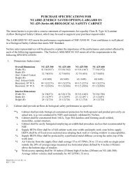
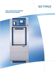
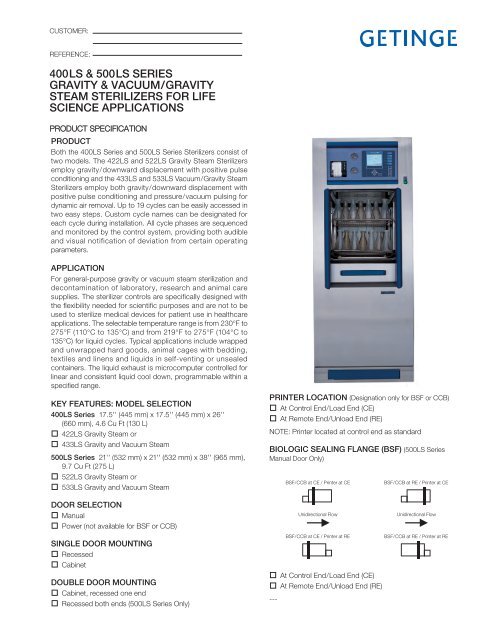
CUSTOMER:REFERENCE:400LS & 500LS SERIESGRAVITY & VACUUM/GRAVITYSTEAM STERILIZERS FOR LIFESCIENCE APPLICATIONSPRODUCT SPECIFICATIONPRODUCTBoth the 400LS Series and 500LS Series Sterilizers consist oftwo models. The 422LS and 522LS Gravity Steam Sterilizersemploy <strong>gravity</strong>/downward displacement with positive pulseconditioning and the 433LS and 533LS Vacuum/Gravity SteamSterilizers employ both <strong>gravity</strong>/downward displacement withpositive pulse conditioning and pressure/<strong>vacuum</strong> pulsing fordynamic air removal. Up to 19 cycles can be easily accessed intwo easy steps. Custom cycle names can be designated foreach cycle during installation. All cycle phases are sequencedand monitored by the control system, providing both audibleand visual notification of deviation from certain operatingparameters.APPLICATIONFor general-purpose <strong>gravity</strong> or <strong>vacuum</strong> steam sterilization anddecontamination of laboratory, research and animal caresupplies. The sterilizer controls are specifically designed withthe flexibility needed for scientific purposes and are not to beused to sterilize medical devices for patient use in healthcareapplications. The selectable temperature range is from 230°F to275°F (110°C to 135°C) and from 219°F to 275°F (104°C to135°C) for liquid cycles. Typical applications include wrappedand unwrapped hard goods, animal cages with bedding,textiles and linens and liquids in self-venting or unsealedcontainers. The liquid exhaust is microcomputer controlled forlinear and consistent liquid cool down, programmable within aspecified range.KEY FEATURES: MODEL SELECTION400LS Series 17.5'' (445 mm) x 17.5'' (445 mm) x 26''(660 mm), 4.6 Cu Ft (130 L)422LS Gravity Steam or433LS Gravity and Vacuum Steam500LS Series 21'' (532 mm) x 21'' (532 mm) x 38'' (965 mm),9.7 Cu Ft (275 L)522LS Gravity Steam or533LS Gravity and Vacuum SteamDOOR SELECTIONManualPower (not available for BSF or CCB)SINGLE DOOR MOUNTINGRecessedCabinetDOUBLE DOOR MOUNTINGCabinet, recessed one endRecessed both ends (500LS Series Only)PRINTER LOCATION (Designation only for BSF or CCB)At Control End/Load End (CE)At Remote End/Unload End (RE)NOTE: Printer located at control end as standardBIOLOGIC SEALING FLANGE (BSF) (500LS SeriesManual Door Only)---BSF/CCB at CE / Printer at CEUnidirectional FlowBSF/CCB at CE / Printer at REAt Control End/Load End (CE)At Remote End/Unload End (RE)BSF/CCB at RE / Printer at CEUnidirectional FlowBSF/CCB at RE / Printer at RE
CROSS CONTAMINATION BARRIER (CCB) (500LSSeries Manual Door Only)At Control End/Load End (CE)At Remote End/Unload End (RE)Extra third shelf – 400LS SeriesExtra third shelf – 500LS Series500LS Series Loading Car, with interior track500LS Series Transfer CarriageQty.Qty.CONTROL PANEL LOCATIONOn UnitWall Mounted Vertically, Remote from unitSTEAM SOURCEHouse steam30 kW integral steam boiler with an automatic feed waterpump as standard (not available with double door 400LSSeries Models)208V 3Ph240V 3Ph480V 3Ph600V 3Ph380/415V 50Hz 3PhLANGUAGE (Select one)EnglishOPTIONSFrenchSpanishBoiler Control and Safety Device (CSD-1). Satisfies stateASME requirements for secondary low water cut-off asrequired by local jurisdiction.Uninterrupted Power Supply (UPS). Provides 115V powerfor up to 30 minutes to complete a cycle in process.304 Stainless Steel piping for clean steam Tissue Cultureappli cations. (Requires house steam to jacket).Thermocouple GlandLoad RTD for temperature control of a liquid loadVacuum Pump (533LS w/House steam only)Automatic Steam Boiler BlowdownWater Saver Package120V220V*OPTIONAL SYSTEMSFree standing electric stainless steel boilers for clean steamFree standing, stainless steel steam to steam generator forclean steamASME Blowdown Separator*Refer to Optional Systems literature for further details and descriptions.QUALITY STATEMENTINTERIOR EQUIPMENTRack with two shelvesSTANDARDS AND CODESConfidence in the Getinge Group is the most important qualitycriterion. This must be the hallmark of all our external andinternal commitments, activities and products. Products andservices supplied by Getinge must conform to the agreed termsand expectations to ensure recommendations for furtherbusiness. The achievement of these quality goals is the basis fora continued competitive and successful enterprise.The sterilizer shall comply with or meet the requirements of:• ASME (Section VIII, Division 1) Code for Pressure Vessels• Canadian Registration Number (CRN) Pressure VesselDesign• Uniform Plumbing Code• ETL Listed to UL 3101-1 by Intertek Testing ServicesMICROCOMPUTER CONTROLS• ETL Listed to IEC 61010-1 and IEC 61010-2-041 by IntertekTesting Services• cETL Listed to CSA C22.2 Nos. 1010.1 and 61010.2.041 byIntertek Testing Services• Seismic Anchoring Requirements per California BuildingCodeGetinge Sterilizers employ a Hitachi 20 MHz micro processor asa dedicated controller (CPU) with 8 MB of RAM. The controlpanel consists of an operator interface panel (called OP30), athermal printer, mechanical chamber and jacket pres suregauges, status indicators, active touch sensitive switches, andcontrols On/Off switch.Controls are located above the door for convenience. Aninternal deflection barrier routes steam vapor and moistureaway from the door and behind the electronic controls tomaintain temperatures at or below temperature limits. Ifspecified, the control panel can be located remotely from thesterilizer with up to 32.8 feet (10 m) of cable. An RS 232 port isprovided for serial communications for central data collection orremote service analysis and is ready for T-DOC ® connection.The OP30 operator interface panel is a durable 1/4 VGA 5.7inch diagonal color screen with 320 x 240 pixels. Below thescreen are five soft keys to access other screens or displaysand to make changes to cycle parameters.A screen saver extends the life of the backlit LCD. Touching anykey illuminates and reactivates the display. Push-buttonswitches, with international symbols and descriptive words,provide door seal and unseal or, if a power door is furnished,vertical movement of the door. Audible and visible operatorfeedback is provided when a selection is made or a faultdescription is displayed. Temperature can be set, controlled anddisplayed in degrees Celsius or Fahrenheit and pressure in psia,bar or kPa. Double door models have one printer (located atcontrol end as standard) and a complete OP30 OperatorPage 2 of 16
Interface at both ends of the sterilizer for full control capabilitiesat either door.The temperature of the discharge water is controlled by atemperature device to be less than 140°F (60°C). This switchalso conserves water usage. The chamber drain is con tinuouslymonitored for the presence of water during a cycle. If water isdetected and cannot be automatically corrected, a high wateralarm alerts the operator. An RS 232 port is provided for serialcommunications for central data collection or remote serviceanalysis. Plot Graph. Displays cycle temperature and pressure incolored graph during a cycle.00:30:00 121.1 CExposure TimeP13 liq LIQUIDS103 LIQ EXHAUSTChamber TempChamber PSIAExposure Temp103.6 C17.45 PSI00:47:3000:13:00CYCLE DOCUMENTATIONThe printer documents cycle performance using special thermalpaper for a permanent record. Thermal printing allows for quietoperation. At cycle completion, a cycle performance record isprinted. Paper is replaced by a “drop in and quick feed” methodand the printed strips can be either accumulated on anautomatic take-up reel, or torn off for individual cycle storage. Alast cycle duplicate print and paper feed switch is provided. Theprinter is located on the control panel as a standard anddocuments the following on a 200-dpi dot matrix printer (1.88''[47.6 mm] wide print width):• Process start time and date, sterilizer name and number, dailycycle number and total cycle count• Cycle selected with time and temperature, with otheradjustable parameters identified• Cycle phase transition points, temperature, pressure and totalcycle time• Process fault information messages with time of occurrence• Summary verification of time at selected temperature(min/max expo sure values)• Cycle verification signature lineOP30 Operator Interface FeaturesThe OP30 color screen is divided into specific sections to Detail. Displays real time process information in text form.SETUP00:03:00 135.0 C 00:20:00Exposure Time Exposure Temp Drying TimeP1 vac PREVAC101 STANDBYChamber TempCham Press/PSIGJacket TempAtmosphere PSIAChamber PSIASteam Table DiffExp. Temp MaxSELECTCYCLE29.1 C0.00 PSI129.9 C14.25 PSI14.25 PSI-13.82 PSI135.6 CPARA-METER00:00:0001:12:44UNSEALSETUPSELECTCYCLEdisplay selection and performance information in a consistentmanner. The top section identifies the time and temperatureselected for the cycle. Below that is the type of cycle selected.The middle por tion provides a choice of three screens to viewactual, real time cycle information. “Pop-up” dialog boxes tochange values appear within parameter selection screens toimplement changes. Parameters are password protected.The three screens are:PARA-METERABORTTIME00:50 Bar Graph. Displays temperature and pressure in a bargraph, with a large, easy to read, time remaining to the end ofthe cycle (averages the last three cycles for each cycle type).SETUP00:30:00 250.0 F 00:30:00Exposure Time Exposure Temp Drying TimeP7 grv GRAVITY102 EXPOSUREChamber TempSELECTCYCLEPARA-METERChamber PSIA250.5 F 30.25 PSI36REMAINING TIME00:36:1500:25:00MOREThe lower portion of the screen provides text alarm messagesand non-critical system messages, both using color displays,and soft key identifications. Navigating the various screens isaccomplished by use of soft keys, directional arrows to movethe cursor and change values, and the Enter key. Up to 19factory recommended cycles are available. Time and tem pera -ture can be changed using a quick edit feature. Each changeprompts operator acceptance by the use of a Yes/Noacknowledgement and a “Save” soft key.Page 3 of 16
For Supervisor access, an alpha-numeric display provideslevels of access for individual operators and service. Using thesoft key labeled “Setup” provides the ability to:• select operating screens• print the last cycle• adjust system menu for setting the calendar• establish users• passwords for each operator• access the “about” selection to identify the model and systemsoftware number• choose language, date format, and temperature and pres suremeasurement• adjust parameters through password accessThe supervisor can also select a Utilities Control feature, whichprovides a seven-day timer for programmed startup and shut -down of the sterilizer. The Utilities Control System shuts offwater and steam to the unit to conserve energy. Cycles runningbeyond the programmed shutoff time will be completed. Finally,an optional Automatic Steam Boiler Blow down System can beprogrammed to blow down the steam boiler automatically oncea day, while cooling hot condensate through internal piping.This is typically scheduled during off-peak time.The factory recommended cycles available for use are:MODELS 422LS and 522LS (12 total cycles)• 6 Gravity cycles of 30 minutes exposure at 121°C (250°F)with 30 minutes dry time• 6 Liquid* cycles at 121°C (250°F), with 30 minutes exposureMODELS 433LS and 533LS (19 total cycles)• 6 Gravity cycles of 30 minutes exposure at 121°C (250°F)with 30 minutes dry time• 6 Pre-Vacuum cycles of 30 minutes exposure at 121°C(250°F)• 6 Liquid* cycles at 121°C (250°F) with 30 minutes exposure• 1 Vacuum Leak Test cycle run at 131°C (268°F)PERFORMANCENote: Selection of time and temperatures other than factoryrecommendations require operator verification of the cycleefficacy.*The liquid cycle, if used, is not intended for the sterilization of liquids useddirectly for patient contact.When installed and connected to specified utility services, thesystem provides accurate and repeatable performance. Duringthe timed exposure phase, the temperature will be controlled bythe chamber sensor at 0.5°C (0.9°F) above the set point(±0.2°C). Temperature selectivity is in 0.1°C (0.1°F) increments.Timing functions are selectable in one-second increments, andCYCLE PROGRESSIONaccuracy is within 0.04%. Temperature is controlled by a timeproportioning continuous algorithm, called Proportional Integral(PI). A battery with a 10 year life holds programmed cycle valuesin memory. In the event ofa power interruption, current cycle status is stored for up to1 minute.• Gravity/Wrapped Goods (pressure pulse pre-con di tioning)a. Conditioning—steam flows into the chamber for a timedperiod, followed by a <strong>series</strong> of positive pressure pulses toremove chamber air.b. Heat-Up—to selected temperature.c. Exposure—selected chamber temperature is attained andtimed.d. Exhaust—chamber vented to atmospheric pressure.e. Dry—filtered air is drawn through chamber for the durationof time selected. (Either Gravity or Vacuum Dry isselectable; Vacuum Dry is recommended.)f. Cycle Complete—signaled by a tone, display messageand light.• Prevac/Wrapped Goods (<strong>vacuum</strong>/pressure pulsing preconditioning)a. Conditioning—steam flows into the chamber for a timedperiod, followed by a <strong>series</strong> of pressure/<strong>vacuum</strong> pulses toremove chamber air.b. Heat-Up—to selected temperature.c. Exposure—selected chamber temperature is attained andtimed.d. Exhaust—chamber vented to atmospheric pressure.e. Dry—a <strong>vacuum</strong> is created for the duration of the timeselected. Filtered air is admitted at the end of the dryingtime, chamber to atmospheric pressure.f. Cycle Complete—signaled by a tone, light and displaymessage.• Liquids—a. Conditioning— steam flows into chamber for a timedperiod to remove air.b. Heat-Up—to selected temperature.c. Dwell— allows liquid loads to reach drain temperaturePARAMETER ADJUSTMENTS(when liquid RTD is not used).d. Exposure—selected chamber temperature is attained andtimed.e. Exhaust—an adjustable linear exhaust.f. Cycle Complete—signaled by a tone, light and displaymessage.Utilizing a service software utility tool, an authorized service rep -re sentative can adjust and modify the following cycleparameters:CONSTRUCTION• Set the number of pre-conditioning pulses.• Set the height of positive pre-conditioning pressure pulses.• Set the depth of negative pre-conditioning pressure pulses.Page 4 of 16
• Set over-drive.• Adjust liquid cycle dwell time.• Adjust liquid cycle exhaust rate.The chamber is constructed of an inner shell reinforced by a<strong>series</strong> of “U” channels that form the outer jacket of the chamber.The gasket ring and backhead (on single door models) areformed and welded to the chamber body. Chamber material is5 mm (0.197'') thick and door material is 6 mm (0.236'') thick,and both are constructed of Stainless Steel, Type SA240 Gr.316Ti. The jacket material is also 316Ti. The interior chamberfinish is polished to a high luster finish. All pressure vesselconstruction meets ASME code requirements for workingpressures up to 45 psig (310 kPa). The gasket ring holds acontinuous, one-piece silicone gasket, 0.63'' (16 mm) indiameter. The body assembly is thermally insulated with 1.5''fiberglass insulation and is double thick between the jacket “U”channels.A steam baffle is provided to prevent con densation from wettingVERTI-GLIDE DOORthe load. An extra threaded opening permits passage ofthermocouple leads to monitor interior and loadtemperatures. Steam connection to the jacket and chamber is316L material. A manual gasket retract valve is provided foremergency chamber access. When rack and shelves aresupplied, shelf adjustments will be approximately every 2.5''(63.5 mm). Individual rack supports and shelves shall be easy toremove for cleaning.The vertical sliding door is counterbalanced for ease ofoperation. When open, it is totally out of the way, allowing safeand complete access to the chamber. Opening or closing themanual door requires only gentle upward or downward handpressure. The optional Power Door is operated by a foot switch,and the door will stop automatically if an obstruction isencountered. If the foot switch is actuated while the door isopening or closing, the direction will be reversed. The PowerDoor can be opened or closed manually. At the beginning of theBIOLOGIC SEALING FLANGE (BSF)cycle, steam pressure behind the gasket automatically seals thedoor and retracts automatically at the end of the cycle. Sealingis positive and consistent. The gasket is recessed for addedprotection and long life. Once the cycle begins and the chamberis pressurized, the door cannot be opened. A safety switchprevents steam from entering the chamber when the door is notin the closed position. The door is insulated with fiberglassinsulation and covered with a stainless steel panel.When specified, a 1/4'' thick, carbon steel, inner flange plate isseal welded around the chamber periphery. The flange plate ismated to the 3/8'' thick wall frame installed in the building wall.The wall frame is shipped early as directed. Studs welded onapproximately three-inch centers are located around the flangeplate and the wall frame. The mating surfaces are gasketed witha 1/4'' thick Buna-N rubber gasket using stainless steelclamping bars, nuts and lock washers. The completedassembly of the sealing flange and wall frame provides anairtight seal, which then prevents passage of airbornemicroorganisms from a “con taminated” room to a “clean” room.Any necessary pene tra tions in the flange for wiring or plumbingshall be through potted fittings. Infiltration tests show no crosscontamination leakage through the sealing flange with pressuredifferential of 0.22 psig (6'' W.C.). Unidirectional door operationis standard, meaning that one door is sealed at all times, andCROSS CONTAIMINATION BARRIER (CCB)once the designated “Control End” (CE) door is opened, thesterilizer must complete a successful cycle before the doordesignated Remote End (RE) can be opened. Full operatorinterface is provided at both doors with the printer designated atone door (CE or RE). An emergency backup system is providedto maintain the door gasket in the event of utility loss.Compressed air is used as the medium for gasket seal.The Cross Contamination Barrier has the same inner flangePANELINGplate as the BSF, and is used when a barrier to maintain an airdifferential is needed. Sheet metal paneling is supplied to spanthe distance from the flange plate to the wall opening and issealed with caulking compound, creating the barrier separation.Electrical or plumbing penetrations through the flange plateshall be compression fittings. Compressed air is used as theINTEGRAL STEAM BOILERmedium for sealing the sterilizer door gaskets. Uni directionaldoor operation, as described for BSF, is standard.The front paneling is constructed of nominal 0.050'' (1.27 mm)300 <strong>series</strong> #3 brush finish stainless steel and is hingedfor easy access to com ponents, the manual gasket retract valveand, if specified, the electric steam boiler. The trim panels areSTEAM BOILERbuilt-in to fit within a recessed wall or optional cabinet. Whenspecified, the cabinet model will be made of the same material.The steam boiler will have a 30 kW capacity at standardvoltages, and be integral with an automatic fill valve to ensurethe correct water level at all times. The sterilizer control on/offswitch controls the boiler control power (115V). The steamboiler is auto matically controlled to generate and maintain asupply of steam to the sterilizer at minimum of 40 psig (3.72bar). An automatic feedwater pump is provided as standard.CONTROLS & FEATURESThe integral steam boiler heating system includes:11. On-off selector switch with power light. Control power willbe re moved from the steam boiler when “control off” isselected.12. An adjustable pressure control and a high-limit control.13. Adjustable over-pressure cutoff.14. Automatic fill valve to maintain the correct water levels at alltimes.Page 5 of 16
15. An ASME, UV rated 100-psi pressure relief valve.16. Magnetic contactors for heater circuit, visible water levelgauge, safety relief valve and manual drain blowdown valve.17. A high-water cutoff safety feature prevents water fromentering the sterilizer.18. Full-size, stainless steel drip pan with leak detection andautomatic system shutdown.9. During the blowdown function for either manual or auto -matic operation, hot condensate flows through the lowerpiping and is condensed by cold water.WARRANTYGetinge USA, Inc. warrants that each sterilizer is carefullytested, inspected and leaves the factory in proper workingcondition, free from visible defects. Sterilizers are warranted forone year from the start of the warranty, including parts and labor(excluding ex pend able parts). The ASME pressure vessel isfurther war ranted to the original owner against structural failurefor a period of 15 years from the date of initial operation. Seewarranty pamphlet for complete details.OPTIONS10. Low water kit to meet ASME CSD-1 requirements per localjurisdictions.11. An automatic blowdown that incorporates a motorized ball(shutoff) valve that automatically uses steam pressure tominimize mineral accumulation in the steam boiler. Theseven-day timer allows the user to select a time each day toschedule the blowdown function.OPTIONAL WATER SAVER PACKAGEFeatures and Benefits:• No change in cycle performance• Operator instructions for equipment are unchanged• Flexible mounting schemes allow installation anywherewithin 15 feet of the sterilizer• Significant water usage reducedWhen the is installed and adjusted properly, the system canprovide water savings of 75% or greater. The table below showsaverage savings for various models of Getinge Vacuum-Steamsterilizers when the equipment is programmed for a wrappedgoods cycle with 3 minutes exposure time and a dry-time of 30minutes. Even when installed on <strong>gravity</strong> displacement sterilizersthat require a lengthy dry phase for processing porous loads,the Water Saver can produce significant savings.NOTE: Requires independent electrical serviceWater Consumption Per CycleEquipment: 400/500LSStandard Unit Consumption: 139 gal.With Water Saver package: 25 gal.% Savings: over 75%ENVIRONMENTAL IMPACTGetinge steam sterilizers are designed and constructed with ourenvironment in mind. To aid in the conservation of naturalresources, and in recognition of prevailing EnvironmentalPolicies, in particular ISO 14001, Getinge steam sterilizers aremore than 90% (by weight) recyclable.Under normal operation, Getinge steam sterilizers produce noharmful byproducts. The Getinge steam sterilization process, inand of itself, produces nothing more dangerous than hot drain.Page 6 of 16
Page 7 of 16
Page 8 of 16
Page 9 of 16
Page 10 of 16
Page 11 of 16
Page 12 of 16
Page 13 of 16
Page 14 of 16
Page 15 of 16
S U P P O R TE Q U I P M E NTAddtitional Comments:T R A I N I N GT R A C E A BI LI T YGetinge provides complete solutions for effective andefficient cleaning, disinfection and sterilization in thehealthcare and life science sectors. Our know-howcomprises everything from architectural planning,production and handling equipment, to systems forfull traceability of sterile goods. Our commitmentcovers expert advice, training and long-term technicalsupport.K N O W - H O WDS400/500LS 0509-A © 2008 Getinge USA, Inc. • Getinge is constantly reviewing its products for improvements. Consequently, the actual products may differ slightly from the products pictured and described here.Getinge USA, Inc.1777 East Henrietta RoadRochester, New York 14623-3133 U.S.A.Phone: (800) 475-9040Fax: (585) 272-5116info@getingeusa.com www.getingeusa.comTHE GETINGE GROUP is a leading global provider of equipmentand systems that contribute to quality enhancement and costefficiency within healthcare and life sciences. Equipment, services andtechnologies are supplied under the brands ARJO for patienthygiene, patient handling and wound care, GETINGE for infectioncontrol and prevention within healthcare and life science andMAQUET for surgical workplaces, cardiopulmonary and critical care.