FLM-420-I2 Input interface modules - Alarmes Tucano
FLM-420-I2 Input interface modules - Alarmes Tucano
FLM-420-I2 Input interface modules - Alarmes Tucano

You also want an ePaper? Increase the reach of your titles
YUMPU automatically turns print PDFs into web optimized ePapers that Google loves.
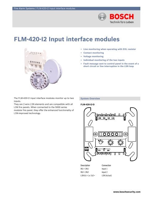
Fire Alarm Systems | <strong>FLM</strong>-<strong>420</strong>-<strong>I2</strong> <strong>Input</strong> <strong>interface</strong> <strong>modules</strong><strong>FLM</strong>-<strong>420</strong>-<strong>I2</strong> <strong>Input</strong> <strong>interface</strong> <strong>modules</strong>▶ Line monitoring when operating with EOL resistor▶ Contact monitoring▶ Voltage monitoring▶ Individual monitoring of the two inputs▶ Fault message sent to control panel in the event of ashort circuit or line interruption in the LSN loopThe <strong>FLM</strong>-<strong>420</strong>-<strong>I2</strong> input <strong>interface</strong> <strong>modules</strong> monitor up to twoinputs.They are 2-wire LSN elements and are compatible with allLSN fire panels. When connected to the 5000 seriesmodular fire panel, they offer the enhanced functionality ofLSN-improved technology.System Overview<strong>FLM</strong>-<strong>420</strong>-<strong>I2</strong>-DDescriptionConnectionIN1+ | IN1- <strong>Input</strong> 1IN2+ | IN2- <strong>Input</strong> 2LSN b1+ | a- | b2+ LSN (in/out)www.boschsecurity.com
2 | <strong>FLM</strong>-<strong>420</strong>-<strong>I2</strong> <strong>Input</strong> <strong>interface</strong> <strong>modules</strong><strong>FLM</strong>-<strong>420</strong>-<strong>I2</strong>-E / <strong>FLM</strong>-<strong>420</strong>-<strong>I2</strong>-WLine conditionInterruptionShort circuitOverall line resistance> 12.000 Ω< 800 ΩContact monitoringThe <strong>interface</strong> module evaluates the operating conditions"open" or "closed". The normal operating condition can beprogrammed for each input. Contact monitoring is carriedout with a pulse intensity of 8 mA. The module detectssignals from a duration of 300 ms.Voltage monitoringVoltage monitoring is carried out between 0 V DC and30 V DC. The programming software can be used to selecttwo threshold values.DescriptionConnectionIN1- | IN1+ <strong>Input</strong> 1IN2- | IN2+ <strong>Input</strong> 2LSN-SHIELDLSN POWER0 V | 0 V | +24 V | +24 VLSN a1- | b1+ | a2- | b2+FunctionsMonitoring functionsShielding cable (if available)LSN power supply (supports for loopingthrough)LSN (in/out)The <strong>FLM</strong>-<strong>420</strong>-<strong>I2</strong> input <strong>interface</strong> <strong>modules</strong> offer threemonitoring functions:1. Monitoring of a line with EOL resistor2. Monitoring of a potential-free contact3. Voltage monitoringThe monitoring functions can be selected for the two inputsindividually by address setting via the programmingsoftware.Line monitoring with EOL resistorOperation with EOL resistor can be programmed for eachinput individually. The standard EOL resistor is 3.9 kΩ.The <strong>interface</strong> module detects• Standby• Triggering in the event of line interruption• Triggering in the event of a short circuit.The following line conditions will be definitely detected ifthe overall line resistance is within the specified ranges:Line conditionStandbyOverall line resistance1500 Ω to 6000 ΩAddress switchesThe addresses of the <strong>interface</strong> <strong>modules</strong> are set using:• DIP switches for <strong>FLM</strong>-<strong>420</strong>-<strong>I2</strong>-E and <strong>FLM</strong>‐<strong>420</strong>‐<strong>I2</strong>‐W• Rotary switches for <strong>FLM</strong>-<strong>420</strong>-<strong>I2</strong>-D.When connecting to the FPA-5000 modular fire panel(“improved version” LSN mode), the operator can selectautomatic or manual addressing with or without autodetection.In LSN mode “classic”, connection to the firepanels BZ 500 LSN, UEZ 2000 LSN and UGM 2020 ispossible.AddressrotaryswitchesAddressDIP switchesOperating mode0 0 0 0 Loop/stub in “improved version” LSN modewith automatic addressing (T-taps not possible)0 0 1-2 5 41 – 254 Loop/stub/T-taps in “improved version”LSN mode with manual addressingCL 0 0 255 Loop/stub in LSN mode “classic”Features of improved LSNThe <strong>interface</strong> <strong>modules</strong> in the <strong>420</strong> series offer all the featuresof “improved” LSN technology:• Flexible network structures including “T-tapping”without additional elements• Up to 254 LSN-improved elements per loop or stub line• Unshielded cable can be used• Downwards compatible with existing LSN systems andcontrol panels.Interface variantsThe input <strong>interface</strong> <strong>modules</strong> are available in various designs:• <strong>FLM</strong>-<strong>420</strong>-<strong>I2</strong>-E type in-built:- Can be built in to standard device boxes inaccordance with EN 60670 (e.g. below standardswitch programs)- For space-saving installation in devices• <strong>FLM</strong>-<strong>420</strong>-<strong>I2</strong>-W type wall-mount (with cover):
<strong>FLM</strong>-<strong>420</strong>-<strong>I2</strong> <strong>Input</strong> <strong>interface</strong> <strong>modules</strong> | 3- Can be built in to standard device boxes inaccordance with EN 60670- For surface mounting in conjunction with theFMX‐IFB55‐S <strong>interface</strong> box.• <strong>FLM</strong>-<strong>420</strong>-<strong>I2</strong>-D type DIN rail:- For installation on a DIN rail in accordance withEN 500022 with included adapter- Can be built in to a <strong>FLM</strong>-IFB126-S surface-mountedhousing.Certifications and ApprovalsVdS certification No.: applied forX compliantFulfills EN 54-18Installation/Configuration Notes• Can be connected to the 5000 series modular fire panel(LSN 0300 and LSN 1500 <strong>modules</strong>) and the classic LSNcontrol panels BZ 500 LSN, UEZ 2000 LSN andUGM 2020.• Programming is carried out via RPS or WinPara.• The LSN connection is established via the two wires onthe LSN line.• A maximum cable length of 3 m is permitted per input.• When mounting the in-built type <strong>interface</strong> modulebelow a switch, a minimum depth of the device box of60 mm is recommended.• The in-built (-E) and wall-mount (-W) versions are fittedwith terminals to allow a second wire pair to be loopedthrough to the LSN power supply of subsequentelements.Parts IncludedType Qty. Component<strong>FLM</strong>-<strong>420</strong>-<strong>I2</strong>-E 1 <strong>Input</strong> <strong>interface</strong> module, type in-built<strong>FLM</strong>-<strong>420</strong>-<strong>I2</strong>-W 1 <strong>Input</strong> <strong>interface</strong> module, type wall-mount, withcover and accessories<strong>FLM</strong>-<strong>420</strong>-<strong>I2</strong>-D 1 <strong>Input</strong> <strong>interface</strong> module, type DIN rail, withadapter and light pipeTechnical SpecificationsElectricalLSN• LSN input voltage 15 V DC to 33 V DC (min. to max.)• Max. current consumptionfrom LSN10.7 mA<strong>Input</strong>s2, independent of each otherContact monitoring• EOL resistor Nominal 3.9 kΩ• Overall line resistance • During standby:1500 to 6000 Ω• Interruption: > 12.000 Ω• Short circuit: < 800 Ω• Max. current (current peak) 8 mAVoltage monitoring• Voltage range 0 to 30 V DC• <strong>Input</strong> resistance ≥ 50 kΩ• Selectable threshold values • 0.8 V DC (± 0.3 V DC)• 3.3 V DC (± 0.3 V DC)• 10.2 V DC (± 0.5 V DC)• 21.2 V DC (± 0.5 V DC)MechanicalConnections• <strong>FLM</strong>-<strong>420</strong>-<strong>I2</strong>-E / W 14 screw terminals• <strong>FLM</strong>-<strong>420</strong>-<strong>I2</strong>-D 7 screw terminalsPermitted wire cross-section• <strong>FLM</strong>-<strong>420</strong>-<strong>I2</strong>-E / W 0.6 to 2.0 mm 2• <strong>FLM</strong>-<strong>420</strong>-<strong>I2</strong>-D 0.6 to 3.3 mm 2Address setting• <strong>FLM</strong>-<strong>420</strong>-<strong>I2</strong>-E / W 8 DIP switches• <strong>FLM</strong>-<strong>420</strong>-<strong>I2</strong>-D 3 rotary switchesHousing material• <strong>FLM</strong>-<strong>420</strong>-<strong>I2</strong>-E / W ABS/PC blend• <strong>FLM</strong>-<strong>420</strong>-<strong>I2</strong>-D with adapter PPO (Noryl)Color• <strong>FLM</strong>-<strong>420</strong>-<strong>I2</strong>-E / W Signal white, RAL 9003• <strong>FLM</strong>-<strong>420</strong>-<strong>I2</strong>-D with adapter Off-white, similar to RAL 9002Dimensions• <strong>FLM</strong>-<strong>420</strong>-<strong>I2</strong>-E Approx. 50 mm x 22 mm (Ø x H)• <strong>FLM</strong>-<strong>420</strong>-<strong>I2</strong>-W Approx. 76 mm x 30 mm (Ø x H)• <strong>FLM</strong>-<strong>420</strong>-<strong>I2</strong>-D with adapter Approx. 110 x 110 x 48 mm (W x H x D)WeightWithout / with packaging• <strong>FLM</strong>-<strong>420</strong>-<strong>I2</strong>-E Approx. 35 g / 130 g• <strong>FLM</strong>-<strong>420</strong>-<strong>I2</strong>-W Approx. 55 g / 155 g• <strong>FLM</strong>-<strong>420</strong>-<strong>I2</strong>-D Approx. 150 g / 235 gwww.boschsecurity.com
4 | <strong>FLM</strong>-<strong>420</strong>-<strong>I2</strong> <strong>Input</strong> <strong>interface</strong> <strong>modules</strong>Environmental conditionsPermitted operating temperature -20 °C to +65 °CPermitted storage temperature -25 °C to +80 °CPermitted rel. humidity< 96% (non-condensing)Safety class II (in accordance with IEC 60950)Protection class IP 30 (in accordance with IEC 60529)System limiting valuesMax. cable length per input3 mOrdering Information<strong>FLM</strong>-<strong>420</strong>-<strong>I2</strong>-E <strong>Input</strong> <strong>interface</strong> <strong>modules</strong>flush-mount type<strong>FLM</strong>-<strong>420</strong>-<strong>I2</strong>-W <strong>Input</strong> <strong>interface</strong> <strong>modules</strong>wall-mount type, with coverFMX-IFB55-S Interface box surface-mount<strong>FLM</strong>-<strong>420</strong>-<strong>I2</strong>-D <strong>Input</strong> <strong>interface</strong> <strong>modules</strong>DIN rail type<strong>FLM</strong>-IFB126-S Surface-mounted housingas retainer for the <strong>interface</strong> <strong>modules</strong> series<strong>420</strong> type DIN rail (-D) or spare housing fortype surface-mount (-S)<strong>FLM</strong>-<strong>420</strong>-<strong>I2</strong>-E<strong>FLM</strong>-<strong>420</strong>-<strong>I2</strong>-WFMX-IFB55-S<strong>FLM</strong>-<strong>420</strong>-<strong>I2</strong>-D<strong>FLM</strong>-IFB126-SEurope, Middle East, Africa:Bosch Security Systems B.V.P.O. Box 800025600 JB Eindhoven, The NetherlandsPhone: + 31 40 2577 284Fax: +31 40 2577 330emea.securitysystems@bosch.comwww.boschsecurity.comAmericas:Bosch Security Systems, Inc.130 Perinton ParkwayFairport, New York, 14450, USAPhone: +1 800 289 0096Fax: +1 585 223 9180security.sales@us.bosch.comwww.boschsecurity.usAsia-Pacific:Bosch Security Systems Pte Ltd38C Jalan PemimpinSingapore 577180Phone: +65 6319 3450Fax: +65 6319 3499apr.securitysystems@bosch.comwww.boschsecurity.comRepresented by© Bosch Security Systems 2006 | Data subject to change without noticeT3271741579 | Cur: en-US, V3, 22 Sep 2006