Metal Hose Guide Mod.1 General, Design, Inst.Instruction - BOA Group
Metal Hose Guide Mod.1 General, Design, Inst.Instruction - BOA Group
Metal Hose Guide Mod.1 General, Design, Inst.Instruction - BOA Group

Create successful ePaper yourself
Turn your PDF publications into a flip-book with our unique Google optimized e-Paper software.
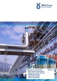
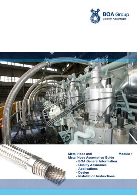
<strong>Metal</strong> <strong>Hose</strong> and Module 1<strong>Metal</strong> <strong>Hose</strong> Assemblies <strong>Guide</strong>- <strong>BOA</strong> <strong>General</strong> Information- Quality Assurance- Applications- <strong>Design</strong>- <strong>Inst</strong>allation <strong>Inst</strong>ructions
<strong>BOA</strong><strong>Metal</strong> <strong>Hose</strong> and <strong>Metal</strong> <strong>Hose</strong> Assemblies <strong>Guide</strong><strong>Metal</strong> <strong>Hose</strong> and <strong>Metal</strong> <strong>Hose</strong> Assemblies <strong>Guide</strong>Modules:1 <strong>Metal</strong> <strong>Hose</strong>s, <strong>General</strong> Information, <strong>Inst</strong>allation <strong>Inst</strong>ructions2 <strong>BOA</strong> Standard Program <strong>Metal</strong> <strong>Hose</strong>s (bulk) and Assemblies3 Annexe/ Standards /CorrosionSummary Module 1page1 <strong>BOA</strong> <strong>General</strong> Information 32 <strong>Metal</strong> <strong>Hose</strong>s <strong>General</strong> 42.1 <strong>Metal</strong> hose 42.2 Corrugated metal hoses – Structure and function 52.3 Strip wound metal hoses – Structure and function 62.4 Technical terms and notes 72.5 Inquiry specifications 83 Quality Assurance 103.1 Approvals / Certificates 103.2 Tests / Laboratory 134 Applications 124.1 Industrial applications 124.2 Aerospace 124.3 Rail traffic 124.4 Automotive 134.5 Solar and boiler industry 134.6 Heating – ventilation – air conditioning 144.7 Gas distribution 144.8 Gas production 144.9 Food industry 154.10 Vacuum applications 154.11 Steel industry 154.12 Special applications 165 <strong>Design</strong> 175.1 Structure and function 175.2 Pressure design 185.3 Calculation of hose lengths 185.4 ISO Standard 10380: 2012 - Excerpt 305.5 EN 14585-1: 2006 - Excerpt 306 <strong>Inst</strong>allation <strong>Inst</strong>ructions 316.1 <strong>General</strong> 316.2 Handling and installation 316.3 <strong>Inst</strong>allation to absorb thermal expansion 326.4 <strong>Inst</strong>allation to compensate for misalignment 336.5 <strong>Inst</strong>allation to absorb vibrations 336.6 <strong>Inst</strong>allation through U-bend to absorb movements 346.7 <strong>Inst</strong>allation instructions for safety gas hoses and LPG metal hoses 35<strong>BOA</strong> AGStation-Ost 1CH-6023 RothenburgSwitzerlandPhone +41 41 289 41 11Fax +41 41 289 42 02sales@ch.boagroup.comwww.boagroup.comSubject to changes13-082
<strong>BOA</strong><strong>Metal</strong> <strong>Hose</strong> and <strong>Metal</strong> <strong>Hose</strong> Assemblies <strong>Guide</strong>1 <strong>BOA</strong> <strong>General</strong> Information<strong>BOA</strong> <strong>Group</strong> – globally activeThe <strong>BOA</strong> <strong>Group</strong> is one of the world's leading manufacturers for flexible mechanical elementsfor the automotive and aerospace industry as well as for a wide range of industrial applications.The headquarters is based in Stutensee near Karlsruhe / Germany.Until August 2006 the <strong>BOA</strong> <strong>Group</strong> operated under the umbrella of the IWKA organization. Today,the <strong>BOA</strong> <strong>Group</strong> consists of 20 subsidiaries and shareholdings in 11 countries. In addition,the <strong>Group</strong> has sales and service offices in the most industrial countries worldwide.With its 1.100 employees, the <strong>BOA</strong> <strong>Group</strong> develops, produces and distributes flexible stainlesssteel components for engine management, exhaust systems, fuel systems and side componentsfor passenger cars and heavy vehicles. In the industrial division, the <strong>BOA</strong> <strong>Group</strong> deliversflexible elements for applications in the Energy sector, Shipbuilding, Rail and Heavy Engine industry.Customized expansion joints are designed for Petrochemical, Chemical as well as Oil &Gas Pipelines. Precision metal bellows and ultra clean metal hoses complete the product rangeand offer high tech product applications in the Vacuum, Semiconductor & Magnet Technologymarket.<strong>BOA</strong> flexible elements include both standard and customized products. Individual solutions aredeveloped in partnership with our customers.<strong>BOA</strong> AG, Rothenburg, Switzerland<strong>BOA</strong> AG, based in Rothenburg near Lucerne, was founded in 1906. About 200 employees areresponsible for development, production, marketing, sales and customer services of highqualityexpansion joints, metal bellows and metal hoses.<strong>BOA</strong> AG is supported by the group partners, subsidiaries and holding companies in France, theNetherlands, Poland, Germany, USA, China and by agencies in all major industrial countries.The partly varying technologies within the <strong>BOA</strong> <strong>Group</strong> form a meaningful symbiosis for coveringthe needs of our customers.<strong>BOA</strong> AG is an internationally recognized company which is among the market leaders in its activityfields.<strong>BOA</strong> is certified according to EN 9100, ISO 9001 and 14001, DIN EN 15085-2 and ISO 3834-2.Product range of <strong>BOA</strong> <strong>Group</strong>Expansion jointsFor pipe systems in chemical and refinery plants, power plant engineering, district heating anddiesel engine manufacturing.<strong>Metal</strong> bellowsAs elastic connections and seals in instruments, valves and fittings, plant and chemical engineering,electrical engineering, vacuum technique, solar and heating installations, automotiveengineering, measurement and control equipment.<strong>Metal</strong> hosesMade of stainless steel, used wherever flexibility and highest reliability are required, e.g. gasdistribution systems in domestic, commercial and industrial buildings, solar and heating engineering,but also in the automotive industry, aerospace and in many other industrial applications.Plastic components<strong>Hose</strong> lines, high pressure hoses, expansion joints and steel piping, whose parts in direct contactwith the flow are covered by plastics, offer big advantages, as plastics are mostly resistantagainst corrosion. Depending on the application, these covers are made of PTFE, PFA orEPDM (rubber).3
<strong>BOA</strong><strong>Metal</strong> <strong>Hose</strong> and <strong>Metal</strong> <strong>Hose</strong> Assemblies <strong>Guide</strong>2 <strong>Metal</strong> <strong>Hose</strong>s <strong>General</strong>2.1 <strong>Metal</strong> <strong>Hose</strong>Application fields<strong>Metal</strong> hoses are an indispensable part of modern technology with its high demands on piping systems for a wide variety of media and temperatures.High flexibility and highest pressure and temperature resistance characterize our product program and allow their use in many areas,notably in heating, plumbing and air conditioning systems, in the oil and gas industry, in the chemical and food industry, in machine and equipmentconstruction, ship building, railway and automotive engineering.Reasons for the use of metal hoses rather than a solution with rigid tubes: Stresses in the pipe systemDue to stresses in the pipe system may occur- assembly inaccuracies- thermal expansion- vibrations- pressure variationsTo compensate for these unwanted stresses, a metal hose assembly provides the following advantages:- no pipe ruptures due to fatigue- no leaky flange connections- no difficulty in replacing pipes having been deformed by high temperatures.Savings in assembly/ disassembly- prefabrication of pipes requires less precision- no adjustment work needed on the hose- assembly inaccuracies are easy to correct- only part of the line must be removed- flexible elements are easier to remove and especially to re-install.This results in:- significant savings in assembly and disassembly of pipe systems- higher flexibility in designing the pipe guides and in case of any modifications.Types of metal hosesBasically there are two types of metal tubes, differing in structure and application:- Corrugated metal hoses or full (all-) metal corrugated hoses- Strip wound metal hoses, with or without sealingCorrugated metal hosesStrip wound metal hosesResistance weldingResistance weldingSelecting the right metal hose depends on its use. Corrugated metal hoses are absolutely leak-tight and are appropriate for high pressure and vacuum Strip wound metal hoses are only of limited leak-tightness and are therefore used mainly as protection, ventilation or aspiration hoses.4
<strong>BOA</strong> <strong>Metal</strong> hose products: OverviewResistance weldedmetal hosesLongitudinallywelded metalhosesStrip woundmetal hosesTrade products<strong>BOA</strong> DUO<strong>BOA</strong> DUO UHP<strong>BOA</strong> SPIRA<strong>BOA</strong> CHEMKING TM<strong>BOA</strong> DEBraids<strong>BOA</strong> SUPRAPARMECA TM<strong>BOA</strong> VS<strong>BOA</strong> PROTEX<strong>Metal</strong> <strong>Hose</strong>Assemblies<strong>BOA</strong> VENTINOXPARNOR ®PARRAP ®<strong>BOA</strong> VSHPTHPXHP2.2 Corrugated metal hoses – Structure and functionPrinciple of annular corrugation (parallel)/ helical corrugation (spiral)Today, the requirements for metallic piping with regard to pressure resistance, temperature, vacuum leak-tightness and corrosion resistanceare very high and still increasing. <strong>BOA</strong> offers a wide range of all-metal hoses meeting these requirements.There are two types of corrugated metal hoses, which differ by the geometry of the corrugation: annularly corrugated metal hoses (parallelcorrugation) and helically corrugated metal hoses (spiral corrugation).Annularly corrugated metal hose(parallel corrugation)Helically corrugated metal hose(spiral corrugation)For the manufacture of corrugated metal hoses, various methods are used: Longitudinally welded corrugated metal hosesFrom a thin metal strip, a tube is formed and longitudinally welded. Then the tube is mechanically or hydraulically formed into a flexible corrugatedhose. With this method, parallel and spiral corrugated metal hoses can be manufactured. Resistance welded metal hosesA narrow metal strip is formed into a double-S-shaped profile, and then wound around a mandrel in a way that one strip edge is overlapping thenext one. The overlapping area is metallically connected by means of roller resistance welding.This method is a <strong>BOA</strong> invention and only allows the production of helically corrugated metal hoses.The shape of the corrugation profile is decisive for the metal hose’s flexibility. Upon bending, the outer corrugations are stretched and the innercompressed. Depending on the height and width of the profile, the flexibility is changing. Although the reduction of the wall thickness increasesthe flexibility, at the same time the pressure resistance is reduced.5
BraidingIn order to increase their pressure resistance, the corrugated metal hoses get single or multiple braids. The material of the wire netting is usuallysimilar to the corrugated metal hose. For corrosion relevant or economic reasons, however, completely different materials for the corrugatedhose and the braid may be chosen. The braiding bears the full mechanical stress which must be absorbed by a metal hose connection. At highpressures, the inherent pressure resistance of the metal hose is almost negligible. The pressure resistance of braided metal hoses is manytimes higher than of metal hoses without braiding. Ultimately the braid alone is load-bearing.Braiding machineBraids made of stainless steelPressure and temperature rangesCorrugated metal hoses can be used for pressures up to 350 bar or vacuum. The temperature resistance is dependent on the material, forstainless steel hoses it is guaranteed up to 600°C. With special materials, even higher temperatures are possible. However, when designingmetal hoses, the material-dependent pressure reduction factors must be considered. Applications in the cryogenic range are possible down toapproximately -270°C without pressure reduction.<strong>BOA</strong> corrugated metal hoses are manufactured with an inner diameter of 5 to 300 mm.High pressure metal hoses forgas bottlesUse of metal hoses in a wasteincineration plant2.3 Strip wound metal hoses – Structure and functionPrincipleStrip wound metal hoses are manufactured by winding up a cold rolled, profiled metal strip onto a mandrel in a helical (spiral)-like way. Due tothe profiling, the spirally rotating windings are slidably connected to each other. Thus, high flexibility and elasticity of the strip wound metal hoseis achieved.6
SealingThe sealing of the metal hose is mainly made by inserting a sealing thread during the winding process into a specially profiled sealing box.More and more, however, metallic sealed strip wound hoses become important. In this case, the additional sealing thread is completely unnecessary.However, in contrast to the all-metal corrugated hose, the leak-tightness of a strip wound metal hose is always limited and thereforethey are not suitable for conveying liquids and gases. They are mostly used as protection hose against outside mechanical influences or asventilation or aspiration hoses for the transport of lightweight materials.MaterialAs basic material, surface-refined steel strips, zinc or nickel plated or chromed are used, as well as stainless steel strips of various quality, ornon-ferrous metals such as brass, bronze, tombac, aluminum or aluminum alloys. For sealing, cotton, rubber, fibreglass or thermo-specialthreads are used. In most cases, <strong>BOA</strong> products are made of stainless steel, using fibreglass as sealing.ProfileStrip wound metal hoses are available in round or polygonal cross-sectional shapes, and the profile shapes range from a simple hook profile tothe crush resistant double overlapped profile.<strong>BOA</strong> DE<strong>BOA</strong> PROTEX2.4 Technical terms and notes<strong>Metal</strong> hoses, metal hoseBulk product without fittings, basic material (semi-finished product) for assembly.Braid, braidingDepending on the braiding type, with a wire braid, the pressure resistance can be increased in various steps. This creates a force-fit connectionbetween the fittings mounted on both sides, which, by absorbing the pressure reaction forces, prevent an uncontrolled expansion of the hoseassembly. For the braid, high-quality chrome-nickel steel 1.4301 (similar to AISI 304) is used.End ring<strong>Metal</strong> end ring covering the braid extremity, to enable a neat connection between the fitting and the braided metal hose.<strong>Metal</strong> hose fittingConnecting part to integrate the metal hose assembly into the existing pipe system (thread, screw joint, flange, coupling, etc.)AssemblyAssembly of metal hoses with fittings by welding, soldering or pressing including all associated preparatory and finishing work.<strong>Metal</strong> hose assemblyCompletely assembled metal hose, with or without braiding, with fittings, tested.Anti-bucklingSpiral spring or supporting hose, attached to the metal hose ends to reduce the bending stress at the joints between metal hose and fittings.Protection spiralElastic spiral over the entire length of the hose assembly to protect the metal hose and its braid against mechanical damage.Protection hoseExterior protection (typically a strip wound metal hose) over the entire length of the hose assembly to protect the metal hose and its braidagainst mechanical damage.Nominal size DNCharacteristic parameter of standard diameters. This value approximately corresponds to the inside diameter in mm.Nominal pressure PNThe nominal pressure rounded down according to EN 1333, resulting from the maximum admissible design pressure.7
Nominal length NLTotal length of a metal hose assembly including hose fittings. Permissible length tolerances see section 5.3 "Calculation of hose lengths."Bend radiusRadius of a circular arc in relation to the hose axis. The ISO 10380 standard distinguishes between the static - for single movement (bendingtest) - and the dynamic bend radius - for frequent movements and /or pressure pulses (fatigue test). Falling below the minimum bend radiusshortens the life of the hose assembly (see section 5, "<strong>Design</strong>").MediumNature and composition of the material to be conveyed, the hose assembly is determined for.2.5 Inquiry specificationsWhile planning the installation of metal hoses and metal hose assemblies ask for technical support. To collect the basic information needed forhose designing, please use the checklist below.Include, if possible, an installation sketch.Copy the following checklist if necessary.Checklist: <strong>Metal</strong> hosesCompany:____________________________________________________________________________Address:______________________________Phone:_______________________________Administrator:__________________________ZIP/ town/country:______________________________Fax:_________________________________________E-mail:_______________________________________Quantity ________ pcs DN _______ mm NL ______________ mm<strong>Hose</strong> type: <strong>BOA</strong>-DUO <strong>BOA</strong>-SPIRA <strong>BOA</strong>-SUPRA ____________ ______________ __________________<strong>Hose</strong> material: 1.4541 1.4404 1.4571 ____________Braid: without with 1 braid (type A) with 2 braids (type B)Connection parts: 1st side2nd sideType: _______________________ ____________________Material: _______________________ ____________________Remarks: ___________________________________________Other: anti-buckling insulation protection hose _________________________________________________Operating conditions Piping PED 97/23/EC ContainerFor pipingType of fluid:___________________________________________ group 1: dangerous gaseous / dangerous liquid group 2: innocuous gaseous / innocuous liquidFor containers, required customer’s indication: Container, category _______________________Fluid type: _______________ -_________________Fluid group: ________________ -_________________Inspection authority ___________________________________Maximum working pressure PS: ______bar constant pulsatingMinimum working pressure PS: ______bar (if also used in vacuum)8
Maximum working temperature TS:Minimum working temperature TS:______°C______°C (if also used below 0°C)<strong>Inst</strong>allation straight 180° bend 90° bendOscillations: amplitude ____ mm frequency ____ HzTests: standard PED 97/23/EC special _________________________________________Inspection certificates: EN 10204-2.2 EN 10204-3.1 EN 10204-3.2 Conformity declaration according to PED 97/23/EC Conformity certificate issued by the inspection authority<strong>Design</strong>ation: standard EN 10380 customer’s indication according to PED 97/23/ECPackaging: standard special customer’s indicationIssued by:Date:Signature:________________________________________________________________________________________________<strong>Inst</strong>allation sketch:9
<strong>BOA</strong><strong>Metal</strong> <strong>Hose</strong> and <strong>Metal</strong> <strong>Hose</strong> Assemblies <strong>Guide</strong>3 Quality Assurance3.1 Approvals / Certificates<strong>BOA</strong> metal hoses are designed, calculated, manufactured and tested following latest professional and state of the art standards. Regular inspectionsby accredited authorities for enterprise certification confirm the efficient and professional continuity of <strong>BOA</strong> process management.Company approvalsEN 9100ISO 9001ISO 14001Euro-QualiflexISO 3834-2DIN EN 15085-2Quality Management for Aerospace applicationsQuality ManagementEnvironment ManagementQuality Management SystemCertification as welding companyWelding of Railway vehicles and componentsPED ConformityPressure Equipment Directive PED 97/23/EC (and SR 819.121)authorized for CE markingSwiss Association forTechnical InspectionsRegulations 201, 501and 704Germanischer LloydEuro-QualiflexProduct approvalsTo cover the particular market orientations, we are in possession of the necessary product type approvals, issued by accredited certificationauthorities.Deutsche Vereinigung des GasundWasserfachesÖsterreichische Vereinigung für dasGas- und WasserfachSchweiz. Verein des Gas- undWasserfachesCERTIGAZ, mandated by AFNOR AssociationFrançaise de NormalisationBureauVeritasDet NorskeVeritasRina NKIP Lloyd's Register10
3.2 Tests / Laboratory<strong>BOA</strong> metal hoses may be subject to various quality tests and inspections. The scope of the testing program follows the requirements and wishesof the customer or the design and production standards, as well as the inspection authority’s conditions.Product quality however is a matter of production standards and not of the subsequent tests. Those tests only confirm the rated required qualitylevel. Therefore our production methods are generally based on a high quality level. Additional tests should be required only where the applicationimperatively demands it. If in a particular case design evidence is requested, the requirements must be clearly specified for a review of thepermissible operating data in our factory.Non-destructive test methodsDestructive test methodsTP - water pressure testLT - leak-tightness test with air or nitrogen underwaterLT - leak-tightness test with air and foaming agentsat the welds (soap bubble test)RT - X-ray testPT - dye penetration testLT - helium leakage test (
<strong>BOA</strong><strong>Metal</strong> <strong>Hose</strong> and <strong>Metal</strong> <strong>Hose</strong> Assemblies <strong>Guide</strong>4 Applications4.1 Industrial applicationsThe rapid industrial development means to machinery and electrical equipment ever increasing demands in terms of quality and reliability.Performance, durability, temperature and pressure are increasing; the material is subjected to the uttermost. Increased production and automationdo no longer allow operational failures. Therefore functionally reliable hose connections with a long life span are required. All-metal hosesprovide best guarantee for it.Double-walled, helically corrugated and braided metal hoses, from nominal diameter DN 5 toDN 300 have proven to take up vibrations very well. The double-walled hose gives majorsafety and the corrugations held low result in a small flow resistance. On installation site,they offer great benefits, and their application is simple because the restrictions made for thevibration absorbers regarding reaction forces do not exist. Reaction forces also occur in themetal hoses. But those are absorbed by metal braiding, so that anchor points and vibratingunits will not be charged by this thrust.The <strong>BOA</strong> metal hose program offers:• DN 5 to 300• single and double-walled• helically or annularly corrugated• assembled with standard or customerspecific fittings• galvanized or stainless steel design4.2 AerospaceIn the aerospace industry safety, reliability and efficiency are of highest priority. Today's aerospace technology is subject to constant and rapidchanges. Our engineers take up this challenge using their expertise and experience in order to improve continuously the performance anddurability of our products.<strong>BOA</strong> stainless steel hoses are suitable as fuel lines, which are exposed to high temperaturesand strong vibration. They are used as flexible hose lines for engine control in modern trainingaircrafts or as protection of cable controls in large commercial aircrafts of the latest generation.Both in the air and in the space they meet the high quality standards for life span and maintaintheir functionality even after many years of use.Cable protection for controlling the flaps on the A3804.3 Rail traffic<strong>BOA</strong>’s flexible components ensure that at any speed, even under extreme pressure andtemperature conditions, mechanical vibrations are safely absorbed. They compensatefor thermal expansion and protect sensitive controls and electrical cables. Flexible hoseand bellows elements ensure entire cooling and exhaust gas systems. In the rail vehicletechnology, where safety, reliability and comfort are of utmost importance, devices,components and systems made by <strong>BOA</strong> play an important role as quality components atcrucial intersections.<strong>BOA</strong> metal hose assemblies are usedfor cooling and air conditioning systemsof locomotives, as aeration andventilation systems for switchgears inhigh speed trains or as vibrationInsulating hoses for pantographsabsorbers. <strong>Metal</strong> bellows make thecompensation arch in exhaust systems,expansion joints are used in the turbochargers of diesel locomotives and various specialvehicles for rail maintenance. Plastic hoses are used as pantographs for railcars, trams,metropolitan rail, subways, etc.12
4.4 AutomotiveThere is hardly another technical consumer product with as high and as special safety requirements on system partners as the vehicle technology.Often complex tasks have to be solved with the highest standards of quality and process reliability. This challenge is faced by a team ofexperienced engineers in our development department.In close cooperation with the customer, the components are developed and designed. To optimize the elements, computer-aided calculationprograms are used and extensive, practical tests series are performed.For a clean environment, more and more metallic filler necks and fuel lines are used, in order to prevent the leakage of methane into the atmosphereand to contribute to the reduction of the greenhouse effect.Automotive: filler neckFuel line4.5 Solar and boiler industryThe production and use of renewable energy sources, including in particular the solarenergy, is growing faster than average in the coming years. Nationwide conditionshave been established taking into account this need. Many companies are workingsuccessfully in the field of renewable energies, expecting in the near future a muchhigher than average growth.Annular corrugated hose assemblies (parallel corrugation) are very suitable for theconnection of individual solar panels. The assembly cost is low because the bendradii of annular hose lines can be kept small and assembly may be done on site. Thiseliminates the inconvenient and expensive soldering and welding work, and thermalexpansions caused by temperature variations are compensated.Solar panel connections- heat exchanger units- insulated connection lines- quick couplings for installation on siteHeat exchangerWater supplyIn the creation or renovation of residential and business buildings, energy saving standards are nowadays very important. In order to achievean optimal energy efficiency concept with as much as possible energy production and use, the installation of a properly sized energy storagedevice is essential. For this purpose, <strong>BOA</strong> metal hose assemblies with their large surface area are very suitable as refrigerant or heat carrier.They also have proven themselves as flexible connections to auxiliary devices such as accumulators, or as gas lines inside the device.13
4.6 Heating - ventilation - air controllingTo save money and time, design and engineering offices increasingly use flexible metal hoses instead of rigid connection elements. Boilers,chillers, dishwashers and washing machines can be easily installed without soldering and welding works. In addition, they compensate for inaccuraciesin installation, compensate for thermal expansion caused by temperature fluctuations and avoid vibration and noise transmission. Thematerial being stainless steel, they easily meet the requirements for corrosion resistance, diffusion and aging resistance.Vibration absorbers JOTA/ KAPPA with screw connectionsCompensation through U-bend metal hose assemblies4.7 Gas distributionFor the flexible connection of gas cookers and other gas appliances such as gas grills, patio heater or gas laundry driers to rigid supply tubing orgas bottles, <strong>BOA</strong> manufactures safety gas hoses disposing of the necessary country specific approvals. All <strong>BOA</strong> safety gas hoses are characterizedby their high quality and their long service life. A selection of different gas plugs completes the assortment.Using the <strong>BOA</strong>GAZ ® system, consisting of flexible corrugated stainless steel tubing (PLT) and screw connections made of brass, gas installationsinside the house – from the gas meter to the gas outlet – can be realized neatly and in a time saving manner.4.8 Gas productionThanks to the high quality and absolute reliability of our stainless steel corrugated hoses, they are used forconveying industrial and medical gases under high pressure up to 300 bar, as well as for the transfer ofliquefied gases at temperatures down to -271.5°C.<strong>BOA</strong> metal hoses have proven to remain leak-tight even in tough conditions and to reliably take up the frequentmovements or pressure changes during the filling of gas bottles or gas containers. Also the fittings,highly stressed by frequent assembly and disassembly, withstand the high loads due to excellent quality.<strong>BOA</strong> high pressure metal hoses as flexible connecting elements offer:high safety level thanks to double-wall corrugationhigh pressure resistancehigh flexibilitydiffusion resistancecustomer specific designs14
4.9 Food industryIn the past, the brewery and dairy industries exclusively used rubber or plastic hoses. Theircleaning was considered unproblematic. The big disadvantage was that this quality hoseshad to be replaced almost every year due to material aging and therefore no longer guaranteedsterility. After a thorough market investigation, some years ago <strong>BOA</strong> put a new producton the market, the annular corrugated stainless steel tubing. Tests showed that after rinsingthis hose appeared to be bright metal inside. The better cleaning effect after rinsing is on theone hand due to the smooth inner surface, a result of the hydraulic forming process. On theother hand, even though each parallel corrugation represents a real obstacle, a wide, deepcorrugation profile avoids inhibiting double vortices. Thus, the rinsing process removes allresidues from the corrugations. The asymmetric corrugation profile still guarantees very highflexibility.In contrast to rubber and plastic hoses, <strong>BOA</strong> metal hose assemblies may be cleanedwith hot steam; they are very flexible and resistant to pressure, ageing and aggressivechemicals. They can be used at high temperatures, are tasteless and have a very favorableprice-performance ratio. The abbreviation CIP stands for "Cleaning in Process", i.e.the metal hose line is rinsing itself free while the product is flowing through, and it mustnot be disconnected for cleaning.Use of a metal hose assembly in a brewery4.10 Vacuum applicationsToday's standard of living highly depends on the vacuum technology and its process engineering applications. Without vacuum we would notknow many achievements of modern life, such as CDs, powerful computers, monitors, coated glasses and window glasses, food packaging, X-ray equipment, high performance microscopes and many other things we take for granted in our daily life.The flexible connections for the vacuum sector,specially developed by <strong>BOA</strong>, meet thehigh quality requirements of high and ultrahigh vacuum. The connections made of singleplyannularly corrugated metal hoses made ofhigh quality chrome-nickel steel are designedto make them operating with as little strains aspossible on the connecting pieces. They aresuitable for taking up axial, lateral and angularmovements and for vibrations absorption.Provided with most varying connecting parts,these metal hoses are used e.g. in vacuumfurnaces or as capillaries for semiconductorequipment.Equipped with small flanges ISO-KF, clampingflanges ISO-K, or CF according to DIN 28404,they connect vacuum lines efficiently and in a time saving manner, ensuring high leaktightness(leakage rate
4.12 Special applications<strong>BOA</strong> offers a range of services focused on problem solving and performance improvement, includingapplication test: performance analysis (dynamic and static) under simulated and real conditions.in-house laboratory: mechanical testing, material and failure analysis, consulting on material and welding methods.FEM calculations: engineering analysis, including Finite Element Analysis, static analysisTo ensure optimal customer service, each customer is assigned to a <strong>BOA</strong> service team consisting of engineers, quality managers and customerservice staff. These cross-functional teams ensure that all aspects of customer satisfaction are met, from products integrity to delivery andmodified designs. As a small and directly addressable team, these people offer a fast, consistent, and personal communication with our customers.16
<strong>BOA</strong><strong>Metal</strong> <strong>Hose</strong> and <strong>Metal</strong> <strong>Hose</strong> Assemblies <strong>Guide</strong>5 <strong>Design</strong>5.1 Structure and function5.1.1 IntroductionFor most practical applications, the fatigue life of metal hose assemblies is not an issue. The flexible connection usually achieves easily the lifespan of the entire plant. Where there are exceptional stresses such as major movements, pressure fluctuations etc., those must be (mathematically)taken into account. If the problem can be captured fairly precisely, in most cases a reasonable design is possible.Nevertheless, despite ever-improving tools, especially in the field of calculation, it is often not possible to predict exactly the service life or thebehavior of a hose. In these cases, it is inevitable to perform (as practical as possible) tests.5.1.2 BasicsThe basics for the design of metal hoses are ISO 10380 (valid worldwide) various national standards, national validity internal standards of the manufacturer, based on years of experienceMany national standards have the ISO 10380 standard as a basis.5.1.3 Fatigue lifeThe fatigue life of a hose assembly can be influenced by the following factors: flow rate of the medium pressure variations (pulsations, water hammers) temperature installation static/dynamic stresses during installation environmental influences (damages, improper handling, etc.)Some of these factors can be influenced by a professional and correct design, others may not be influenced.Concerning the calculation, the fatigue life depends mainly on the parameters working pressure (as a function of temperature) movement installation radiusThese parameters are in the following interdependence:Fatigue life constant Parameter to be influenced Consequencehigher pressure- bigger radius- smaller movementsmaller radius- lower pressure- smaller movementlarger movement- lower pressure- bigger radiusMovement constant Parameter to be influenced Consequencehigher pressure- lower fatigue life- bigger radiussmaller radius- lower fatigue life- lower pressurelonger fatigue life- bigger radius- lower pressureRadius constant Parameter to be influenced Consequencehigher pressure- lower fatigue life- smaller movementlonger fatigue life- smaller movement- lower pressurelarger movement- lower pressure- lower fatigue life5.1.4 Bend radiusThe bend radius is an absolutely crucial parameter when it comes to make a statement concerning fatigue life in case of movements. It isregulated by the ISO 10380 standard. In this norm, metal hoses are divided into four different types: type 1-50: corrugated metal hoses of high flexibility with high fatigue life type 1-10: corrugated metal hoses of high flexibility with medium fatigue life type 2-10: corrugated metal hoses of average flexibility type 3: corrugated metal hoses where only pliability is requiredExcerpt from ISO Standard 10380:"Corresponding radii for pliability tests are given in Table 6 and corresponding radii for fatigue tests are given in Table 8“.In the technical documentation, the static (R static ) and dynamic radii (R dynamic = R N ) are listed. When designing, the correct radius must be selecteddepending on the application.17
5.2 Pressure designAlso the pressure design is generally based on the ISO 10380 standard. It defines that the burst pressure must be 4 times higher than thenominal pressure. However, in certain circumstances and together with the customer, a compromise might be found (e.g. the pressure peakmust not necessarily correspond to the design pressure). In any case, always precise knowledge of operational data is needed to createthe conditions for optimum pressure design.The pressure design is mainly influenced by 3 parameters: working pressure working temperature working ( thermal derating factor k t ) operating behaviour ( dynamic derating factor k d )Calculation of the admissible working pressureTaking into account all operational factors, the admissible working pressure p max adm is calculated as follows:p max adm = PN · k t · k dPN:k t :k d :theoretical maximum operating pressure according to the catalogue tablestemperature derating factordynamic derating factorTemperature derating factor k tThe temperature derating factors for materials and temperatures may be taken from ISO 10380 (Table 3 - Derating factors and limiting temperatures).Below is an excerpt of the mentioned table. If the corrugated hose and the braid are not made of the same material, the lowest valuemust be taken.Materialk to.r. = on requestWorking temperature [°C]-200 20 50 100 150 200 250 300 350 400 450 500 550 6001.4301 1 1 0.88 0.73 0.66 0.60 0.56 0.52 0.50 0.48 0.47 0.46 0.42 o.r.1.4404 1 1 0.88 0.74 0.67 0.62 0.58 0.54 0.52 0.50 0.48 0.47 0.47 o.r.1.4541 1 1 0.92 0.83 0.78 0.74 0.71 0.67 0.64 0.62 0.61 0.60 0.59 o.r.1.4571 1 1 0.90 0.81 0.76 0.73 0.69 0.65 0.63 0.61 0.59 0.59 0.58 o.r.Dynamic derating factor k dk dMovementFlowUniform, frequent movements, oscillations Impact movements, oscillations of large amplitudeof small amplitudeStatic or slow and uniform flow 1.00 0.80Pulsating and irregular flow 0.80 0.50Pressure shocks, pulsating flow 0.50 o.r.o.r. = on request5.3 Calculation of hose lengthsRecognizing the stressThe most important factor in calculating hose lengths is to recognize the stress and the subsequent evaluation of the installation situation. Theinvestigations often end with the set of movement directions and the movements’ size. Most of time, a crucial factor is forgotten, that is themovements’ frequency and their speed. Is it really a movement at a given frequency or is it just a slowly occurring expansion?Example: A slow movement, taking place only 2 times a week, may well be treated as a thermal expansion. This in turn has consequences forthe hose length, etc.<strong>Inst</strong>allation positions should be laid out whenever possible according to installation principles.(see sector 6 "<strong>Inst</strong>allation <strong>Inst</strong>ructions")Principle:In calculating the hose length, for all dynamic tasks, always the dynamic bend radius r dyn must be used, thus also forthermal expansions.To simplify the subsequent equations, first the length „I“ of the connection area is calculated.18
Length of connection area ll = EH + AIn the subsequent equations the dimension „I“ will appear. This dimension defines the length of the connectionarea (I). It is calculated from the length of the end ring (EH) and the protruding length (A) of the fitting.Length of end ring EH:The end sleeve/end ring protects the weld area from overstraining. The length EH (mm) for the calculationof the length l of the connection area may be taken from the table below:DN 5 6 8 10 12 16 20 25 32 40 50 65 80 100 125 150 175 200 250 300EH 16 16 20 20 24 24 28 28 34 34 42 42 54 54 30 30 40 40 50 50Length of fitting A:The protruding length A (mm) of the concerned fitting can be taken either from the technical data sheet„Fittings to <strong>BOA</strong> <strong>Metal</strong> <strong>Hose</strong>s“ or from the “<strong>Metal</strong> <strong>Hose</strong> <strong>Guide</strong>”, Module 2, chapter 3).5.3.1 Straight metal hose assembly for parallel installation offset (static)(Movements perpendicular to the hose plane are not permitted)<strong>Inst</strong>allation type:Application:straight metal hose assemblylateral installation offsetsingular lateral bending(not for repetitive movement absorption!)Equations: cos = 1 – a / (2 · R static )cos must not be 0.5, otherwise theradius R > R static must be taken.NL = 0.035 · R static · + 2 · (Z + l)EL = 2 · R static · sin + 2 · (Z + l)Symbols: a: offset from the axis (mm): bend angle (°)R static : static bend radius (mm)Z: outside diameter of the metal hose (mm)l: length of the hose fitting (mm)NL: nominal length (mm)EL: installation length (mm)19
5.3.2 Straight metal hose assembly for lateral movements(Movements perpendicular to the hose plane are not permitted)<strong>Inst</strong>allation type:Application:straight metal hose assemblylateral installation offset- low amplitude (max. 100mm)- low movement frequencyEquations: NL = 4.5 · (R dynamic · s) 1/2 + 2 · (DN + l)s = (NL - 2 · l) · 2 / (20 · R dynamic )EL NL · (1-0.15 · s / NL)Minimum nominal length NL min = 7 · s + 2 · lSymbols: s: lateral expansion absorption (mm)R dynamic : dynamic bend radius (mm)DN: nominal diameter (mm)l: length of the hose fitting (mm)NL: nominal length (mm)EL: installation length (mm)20
5.3.3 90° <strong>Metal</strong> hose assembly for lateral expansion absorption from one direction(Movements perpendicular to the hose plane are not permitted)<strong>Inst</strong>allation type:Application:90° metal hose assemblylateral expansion absorption in 1 axis- low amplitude (max. 100mm)- low movement frequencyEquations: cos = 1 – s / (2 · R dynamic )The angle must not exceed 60°! cos must be 0.5, otherwise theradius R > R dynamic must be taken.NL = R dynamic · (1.57 + 0.035 · ) + 2 · (DN + l)a = R dynamic + (2 · R dynamic · sin) + DN + lb = R dynamic + R dynamic · (0.035 · - 2 · sin) + DN + lSymbols: s: expansion absorption lateral (mm)a: installation dimension 1 (mm)b: installation dimension 2 (mm)l: length of the hose fitting (mm): bend angle (°)R dynamic : dynamic bend radius (mm)DN: nominal diameter (mm)NL: nominal length (mm)21
5.3.4 90° <strong>Metal</strong> hose assembly for lateral expansion absorption from two directions(Movements perpendicular to the hose plane are not permitted)<strong>Inst</strong>allation type:Application:90° metal hose assemblylateral expansion absorption in 2 axes- low amplitude (max. 100mm)- very low frequencyEquations: cos = 1 – s 1 / (2 · R dynamic )cos = 1 – s 2 / (2 · R dynamic )The angle must not exceed 60°! cos nust be 0.5, otherwise theradius R > R dynamic must be taken.NL = R dynamic · (1.57 + 0.035 · + 0.035 · ) +2 · (DN + l)a = R dynamic + R dynamic · (2 · sin + 0.035 · - 2 · sin) + DN + lb = R dynamic + R dynamic · (2 · sin + 0.035 · - 2 · sin) + DN + lSymbols: s 1 : expansion absorption 1 lateral (mm)s 2 : expansion absorption 2 lateral (mm)a: installation dimension 1 (mm)b: installation dimension 2 (mm)l: length of the hose fitting (mm), : bend angle (°)R dynamic : dynamic bend radius (mm)DN: nominal diameter (mm)NL: nominal length (mm)22
5.3.5 U-bend to take up expansions from one direction(Movements perpendicular to the hose plane are not permitted)<strong>Inst</strong>allation type:Application:vertical 180° bendabsorption of expansion from 1 direction (e.g. thermal expansion)- big amplitude- very low movement frequencyEquations:NL = R dynamic · + 1.57 · s + 2 · lh 1 max = R dynamic + 0.785 · s + lh 2 min = R dynamic + 0.5 · s + lSymbols: s: movement (mm)R dynamic : dynamic bend radius (mm)DN: nominal diameter (mm)l length of the hose fitting (mm)NL: nominal length (mm)h 1 : maximum height of the 180° arc (mm)h 2 : minimal height of the 180° arc (mm)23
5.3.6 U-bend to take up expansions from two directions(Movements perpendicular to the hose plane are not permitted)<strong>Inst</strong>allation type:Application:vertical 180° bendabsorption of expansions from 2 directions (e.g. thermal expansion)- big amplitude- very low movement frequencyEquations:NL = R dynamic · + 1.57 · s 1 + 0.5 · s 2 + 2 · lh 1 max = R dynamic + 0.785 · s 1 + 0.5 · s 2 + lh 2 min = R dynamic + 0.5 · s 1 + lSymbols: s 1 : movement (horizontal) (mm)s 2 : movement (vertical) (mm)R dynamic : dynamic bend radius (mm)DN: nominal diameter (mm)l length of the hose fitting (mm)NL: nominal length (mm)h 1 : maximum height of the 180° arc (mm)h 2 : minimal height of the 180° arc (mm)24
5.3.7 90° bend to take up vibrations<strong>Inst</strong>allation type:Application:90° metal hose elbow or90° dog-legvibrations from all directions- small amplitude- high frequencyDN ≤ 100 DN ≥ 125Equations:NL = 2.3 · R dynamic + 2 · la = 1.365 · R dynamic + lSymbols: a: leg length (mm)R dynamic : dynamic bend radius (mm)DN: nominal diameter (mm)l: length of the hose fitting (mm)NL: nominal length (mm)25
5.3.8 U-bend for vertical movement(Movements perpendicular to the hose plane are not permitted)<strong>Inst</strong>allation type:Application:vertical 180° bendvertical movement- big amplitude- low movement frequencyEquations:NL = 4 · R dynamic + 0.5 · s + 2 · lh 1 max = 1.43 · R dynamic + 0.5 · s + lh 2 min = 1.43 · R dynamic + lSymbols: s: movement (mm)R dynamic : dynamic bend radius (mm)DN: nominal diameter (mm)l length of the hose fitting (mm)NL: nominal length (mm)h 1 : maximum height of the 180° arc (mm)h 2 : minimal height of the 180° arc (mm)26
5.3.9 U-bend for horizontal movement(Movements perpendicular to the hose plane are not permitted)<strong>Inst</strong>allation type:Application:vertical 180° bendhorizontal movement- big amplitude- low movement frequencyEquations:NL = 4 · R dynamic + 1.57 · s + 2 · lh 1 max = 1.43 · R dynamic + 0.785 · s + lh 2 min = 1.43 · R dynamic + 0.5 · s + lSymbols: s: movement (mm)R dynamic : dynamic bend radius (mm)DN: nominal diameter (mm)l length of the hose fitting (mm)NL: nominal length (mm)h 1 : maximum height of the 180° arc (mm)h 2 : minimal height of the 180° arc (mm)27
5.3.10 U-bend for vertical and horizontal movement(Movements perpendicular to the hose plane are not permitted)<strong>Inst</strong>allation type:Application:vertical 180° bendvertical and horizontal movement- big amplitude- low movement frequencyEquations:NL = 4 · R dynamic + 1.57 · s 1 + 0.5 · s 2 + 2 · lh 1 max = 1.43 · R dynamic + 0.785 · s 1 + 0.5 · s 2 + lh 2 min = 1.43 · R dynamic + 0.5 · s 1 + lSymbols: s 1 : movement (horizontal) (mm)s 2 : movement (vertical) (mm)R dynamic : dynamic bend radius (mm)DN: nominal diameter (mm)l length of the hose fitting (mm)NL: nominal length (mm)h 1 : maximum height of the 180° arc (mm)h 2 : minimal height of the 180° arc (mm)28
5.3.11 Straight metal hose assembly for angular movement(Movements perpendicular to the hose plane are not permitted)<strong>Inst</strong>allation type:Application:straight metal hose assembly becomes elbowangular movement in one plane- big amplitude- low movement frequencyEquations: NL = (R dynamic · · ) / 180 + 2 · (l + z)EL = R dynamic · sin + (l + z) · (1 + cos )a = R dynamic · (1 - cos ) + (l + z) · sinSymbols: : bend angle (°)z: additional length for hose ends (mm),see table belowa: distance of the bend (mm)R dynamic : dynamic bend radius (mm)DN: nominal diameter (mm)l length of the hose fitting (mm)NL: nominal length (mm)EL: installation length (mm)Nominal diameter 12 16 - 25 32 - 40 50 - 65 80-100 125-150 200-300DNAdd. length z 25 50 75 100 150 200 30029
5.4 ISO Standard 10380: 2012 – ExcerptTitle:Excerpt:Pipework — Corrugated metal hoses and hose assembliesThe International Standard ISO 10380:2012 specifies the minimum requirements for the design, manufacture, testing andinstallation of corrugated metal hose and metal hose assemblies.It specifies the range for the nominal sizes from DN 4 to DN 300, the pressure range from PN 0.5 to PN 450, the deratingfactors of pressure at elevated temperatures, three hose types with different types of flexibility/ fatigue life of hose assemblies.5.5 EN 14585-1: 2006 – ExcerptTitle:Excerpt:Corrugated metal hose assemblies for pressure applicationsEN 14585-1 characterizes the specific properties of a corrugated metal hose assembly- by the mutual effect of their pressure bearing parts: corrugated metal hose, braid, connecting parts and non-detachableconnections, and- by the opposing requirements on pressure resistance and flexibility.This standard describes the experimental design method (basis PED Annex I, Section 2.2.2)30
<strong>BOA</strong><strong>Metal</strong> <strong>Hose</strong> and <strong>Metal</strong> <strong>Hose</strong> Assemblies <strong>Guide</strong>6 <strong>Inst</strong>allation <strong>Inst</strong>ructions6.1 <strong>General</strong>The metal hose must be protected from mechanical damages such as damaging of braid wires sharp buckling dragging the metal hose on the floor dragging it across sharp edgesWhile installing, make sure that no torsional forces act on the metal hose assembly torsion leads to early failureUnder extreme mechanical stress conditions or at high temperatures the metal hose assembly must be equipped with one of the following outerprotective tubes or accessories: protection hose C150 * protection hose Protex * wire spiral fire protection hose (high temperature applications) safety cable (high pressure applications)* for further information see sector 2.3 Strip wound metal hosesHigh pressure metal hose assemblies with safety cableThe metal hose assemblies must be protected against corrosive environment (chlorides, etc.). In extreme conditions, the following measures arenecessary: outside leak-tight metal hose made of highest quality material (e.g. Incoloy) fire protection hose design relevant measuresThe figures below illustrate some examples of incorrect metal hose assembly installations, frequently found in practice, and how this can beeasily corrected. In case of uncertainty, please contact our experts.6.2 Handling and installationExample 1 correct incorrectLay the metal hose straight and uncoil it to avoid torsion and to fallbelow the minimum bend radius.Example 2Use a saddle or a roller to avoid buckling and, as a result, the hosefrom falling below the minimum bend radius.Example 3<strong>Inst</strong>all the metal hose in neutral position. Torsion leads to early failure.Therefore, as a rule, the metal hose should have one movable connectionend.Example 4Tighten screws evenly crosswise to obtain better sealing.31
Example 5 correct incorrectWhile installing a corrugated hose system through welding or soldering,make sure that the soldering point between fitting and hose is protectedand cooled by a very wet cloth. The open flame must always bedirected away from the hose system. No solder paste containing chlorideshall be used.Example 6For manual use the hose fitting must be protected from bending. Ifnecessary use a rigid pipe elbow.Cover must beextra cooled!Be aware of burnerflame direction!Example 7Don’t install the hose system in compressed position. The braid shallnot shift from the hose.Coiled metal hose (ill. to example 1)<strong>Inst</strong>allation as a U-bend (ill. to example 12)6.3 <strong>Inst</strong>allation to absorb thermal expansionExample 8 correct incorrect<strong>Inst</strong>all the metal hose with lateral prerestraint to make use of the permissiblemovement. Avoid compression.Example 9The metal hose must be installed perpendicular to the expansion direction.The hose must only absorb lateral, no axial movements.Example 10If large lateral movements occur, install in a 90° bend.Example 11Movements may only be absorbed in one plane, the hose direction.Strictly avoid torsion.Example 12If large axial movements are to be absorbed, install the hose in a U-bend to protect it from buckling. In any case, the hose must be connectedvia pipe elbow to the piping system.32
6.4 <strong>Inst</strong>allation to compensate for misalignmentExample 13 correct incorrectCalculate the exact hose length to avoid hose buckling or overstretching.Example 14The hose is too long.Example 15The hose is too short.Example 16The misalignment must not be too large.<strong>Metal</strong> hose assembly extendable to double length (DTFlex)6.5 <strong>Inst</strong>allation to absorb vibrationsExample 17 correct incorrectThe metal hose shall be installed perpendicular to the occurring vibrationsin order to avoid compression of the metal hose in service.Example 18If vibrations occur in two directions, the metal hose shall be installed ina 90° bend.Example 19If vibrations occur in three directions, two hose assemblies are to beinstalled in a 90° display by a rigid elbow.Vibration absorbers in service33
6.6 <strong>Inst</strong>allation through U-bend to absorb movementsExample 20 correct incorrectCalculate exactly the nominal hose length in order not to fall below thedynamic bend radius, which would shorten its fatigue life (for bend radiisee technical data sheet „Technical Information <strong>Metal</strong> hoses and metalhose assemblies“).Example 21For correct connection always use pipe elbows to protect the hose fromoverbending.Example 22 +23Movement is only allowed in the hose axis to avoid torsion which leadsto early failure.TorsionExample 24<strong>Inst</strong>allation of a U-bend system for lateral movements.TorsionExample 25If horizontally installed, the hose weight (medium filled) has to be supported,e.g. through roller or support.34
6.7 <strong>Inst</strong>allation instructions for safety gas hoses and LPG metal hosesThe following instructions must strictly be observed:Always install the gas hose behind a shut off device.The gas metal hose has to be controllable over its whole length and the layout must provide easy replacement.It has to be protected against excessive mechanical stress.While installing, any torsion has to be avoided.Keep a sufficient distance between metal hose and heating source to avoid overheating.Never connect a metal hose to the gas appliance without metallic sealing or special gasket.Never fall below the following bend radii:Safety gas hoses: static: 45 mm; dynamic: 125 mmLPG hose assemblies: static: 32 mm; dynamic: 100 mmCoupling two or several gas metal hoses together is not permitted.Never repair damaged gas metal hoses; they must be replaced.Fix connections of gas metal hoses may be subject to unintentional unscrewing movement due to excessive motion of the appliance andthe resulting torsion. Avoid such movements which could also damage the metal hose.Additional rules for safety gas hoses:Check the tightness of the gas connection with soapy water (or equivalent).Never disconnect fix gas connections (not equipped with safety gas plug) without correct interruption of the gas supply.Movable gas appliances should be connected by hoses provided with a safety gas plug which automatically cuts the gas supply in case ofdecoupling.Gas metal hose assembly provided with safety gas plugGas plug with shutoff valve35
<strong>BOA</strong><strong>Metal</strong> <strong>Hose</strong> and <strong>Metal</strong> <strong>Hose</strong> Assemblies <strong>Guide</strong>Specifications are subject to changes13-08<strong>BOA</strong> AGStation-Ost 1CH-6023 RothenburgSwitzerlandPhone +41 41 289 41 11Fax +41 41 289 42 02sales@ch.boagroup.comwww.boagroup.com36