Console Water Source Heat Pumps - McQuay
Console Water Source Heat Pumps - McQuay Console Water Source Heat Pumps - McQuay
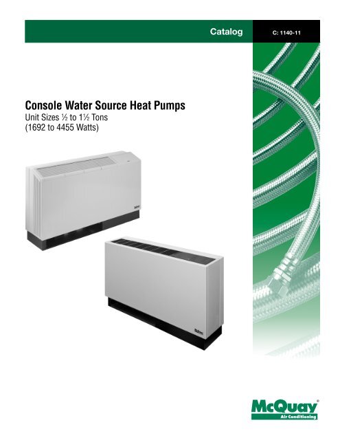
Catalog C: 1140-11Console Water Source Heat PumpsUnit Sizes 1 ⁄2 to 1 1 ⁄2 Tons(1692 to 4455 Watts)®
- Page 3: MANUFACTURER CERTIFIED TO ARI AS CO
- Page 6 and 7: Design FeaturesSlope Top Console Un
- Page 8 and 9: Loop Water ControllerThe Loop Water
- Page 10 and 11: Control OptionsControl TypePrinted
- Page 12 and 13: Supply and Return Water HosesSupply
- Page 14 and 15: Fan PerformanceUnit SizeHigh SpeedC
- Page 16 and 17: Capacity DataUnit size 009 (60 Hz)
- Page 18 and 19: Capacity DataUnit size 015 (60 Hz)
- Page 20 and 21: Capacity data — 50 HertzUnit size
- Page 22 and 23: Capacity DataUnit size 012 (50Hz) a
- Page 24 and 25: Capacity DataUnit size 019 (50Hz) a
- Page 26 and 27: Dimensional Data - High Sill UnitCh
- Page 28 and 29: Thermostat Connection DiagramsMark
- Page 30 and 31: Mark IV Control System — Unit sha
- Page 32: Total Heat Pump CapabilityEnfinity
Catalog C: 1140-11<strong>Console</strong> <strong>Water</strong> <strong>Source</strong> <strong>Heat</strong> <strong>Pumps</strong>Unit Sizes 1 ⁄2 to 1 1 ⁄2 Tons(1692 to 4455 Watts)®
MANUFACTURER CERTIFIED TO ARI AS COMPLYING WITH<strong>McQuay</strong> console water source heat pump units...Quiet, energy efficient, attractive styling.Features:■ Rotary compressor■ Slope top cabinet■ Modern grille and cabinet shape■ Touch-tap membrane switches■ Antique Ivory/Oxford Brown finish■ Slide-out chassis design■ Compact dimension– only 10 3 /4" (273mm) deep.■ Up to 5 unit sizes■ Unique 50 cycle unit sizes■ Continuous or cycle fan operation■ Optional boilerless system electric heat■ Optional plug-in cord and receptacle (fieldinstalled)Featuring:Mark IV . . . . . . . and . . . . . . . MicroTech DDC Controls■ Unit mounted thermostat■ Built-in night setback, load shed andshutdown■ Built-in 2-hour override pushbutton■ Random start and compressor anti-shortcycle protection■ Condensate overflow protection■ Pump restart relay signal■ Unit mounted DDC controller■ Unit mounted return air sensor, discharge airsensor and leaving water sensor■ Unit mounted tenant setpoint adjustment■ Unit mounted override pushbutton■ Night setback, cycle fan and pump restartoperationWATER TO AIRBRINE TO AIRRISO STANDARD 13256-1HEAT PUMPS“<strong>McQuay</strong>” is a registered trademark of <strong>McQuay</strong> International.©2002 <strong>McQuay</strong> International. All rights reserved throughout the world.The information in this catalog supersedes and replaces previous (catalogues)(bulletins) with regards to <strong>McQuay</strong> Terminal AirConditioning products. Illustrations cover the general appearance of <strong>McQuay</strong> products at the time of publication and AAF-<strong>McQuay</strong> reserves the right to make changes in design and construction at anytime without notice.(Rev. 11/02)Catalog 1140 / Page 3 of 32
ISO Performance DataRated in Accordance With ISO Standard 13256-1English UnitsSizeAirFlow CFM<strong>Water</strong> Flow GPMCapacity( (BTUHBTUH)CoolingEERCapacity( (BTUHBTUH)<strong>Heat</strong>ing0072001.74680012.587004. 20092502.29890012.2120004. 20122902.921130012.4150004. 20154803.841570012.6175004. 20195204.661790012.2232004. 2COPSI UnitsSizeAirFlow L/ s<strong>Water</strong> Flow L/ sCapacity(Watts)CoolingC OPCapacity(Watts)<strong>Heat</strong>ingCOP007940.1116923.6621654. 20091180.1422153.5729874. 20121370.1828123.6337334. 20152270.2439073.6943554. 20192450.2944553.5757744. 2Notes:EER = Energy Efficiency Ratio COP = Coefficient of Performance kW = kilowatts L/s = liters per secondCooling capacity is based on 80˚F (27˚C) db, 67˚F (19˚C) wb entering air temperature and 85˚F (29˚C) entering, 95˚F (35˚C) leaving water termperature.<strong>Heat</strong>ing capacity is based on 70˚F (21˚C) db entering air termperature and 70˚F (21˚C) entering water temperature.50 cycle units are not ARI rated.Design FeaturesSlope top high sillConfigurationFlat top high sill<strong>Console</strong> water source heat pumps are available in five coolingcapacity sizes, from 1⁄2 through 1 1 ⁄2 tons, (1757 to 5274 watts).Each is available in four different configurations. Flat top unitsmeet the traditional requirements for a rugged unit. Slope topunits offer a modern look. The high silhouette unit is 25" (635mm)high and the low silhouette unit is only 22 1 ⁄2" (572mm) high. Theoverall unit dimensions are very compact; unit sizes 004 through012 are 46" (1168mm) long and sizes 013 through 019 are 54"(1372mm) long. All units are a constant 10 3 ⁄4" (273mm) deep forminimum floor space and a consistent “look” for all unit sizes.All units incorporate a slide-out chassis concept which ispreferred by many owners, developers and contractors. Theback part of the cabinet (backwrap) is attached to the subbaseand secures to the back wall or floor. The front cabinet simplylifts off, exposing the chassis for field hook-up of water andelectrical connections. The chassis easily slides off the subbasefor service or changeout.CabinetAll cabinets are painted with Antique Ivory baked enamel finishfor a great match to any room. The discharge grilles and subbaseare Oxford Brown on flat top units.The shallow 22˚ slope top cabinet is constructed of 18-gaugesteel. The side pieces are constructed of ABS polycarbonatewith accent lines to match the grille. The grille and door arealso of ABS polycarbonate with unique detail. The “raised” grilleextends to the front and sides for a smooth look as well asproviding a curtain stop in back. Again, the accent lines on thesides follow the grille and control door lines. The discharge grillesdirect the air in an 11˚ angle from the vertical and can be reversedfor a 33˚ discharge angle. The control door has a finger slot andsimply lifts up for access to the controls. Overall, the slope topunit allows minimal airflow interference from curtains and objectsresting on the cabinet while at the same time providing a rugged,aesthetically pleasing look.The flat top cabinet is constructed of 18-gauge steel with aone piece steel grille that meets basic needs with its ruggedconstruction and its 11˚ discharge angle.Discharge Grille – Flat Top UnitsOne-piece stampedCatalog 1140 / Page 5 of 32
Design FeaturesSlope Top <strong>Console</strong> UnitSimple Tap-touch OperationChassisThe slide-out chassis houses the fan section, refrigerant circuitand controls. The air enters through the bottom of the chassisthrough the subbase.The refrigeration system includes a rotary compressor,reversing valve, coaxial heat exchanger, capillary tubes, air coil,high and low side access valves, and safety controls. Accessto the compressor is through a panel. The compressor is isolatedfrom the unit with external vibration mounts and thecompartment is totally insulated. Electrical controls include aunit-mounted return air thermostat, start-stop rocker switch andtwo-speed fan control. The operative controls include athermostat adjustment knob for “warmer-cooler” and membranesystem/fan switches for simple tap-touch operation. Safetycontrols include low temperature (freezestat) and refrigerant highpressure switches. The control box top is removable for accessto all of the controls. Two unique control systems are offered:Mark IV and MicroTech. Each uses a printed circuit board forclean wiring and a low voltage control circuit with a 50 VAtransformer. See “Controls” section for more detailedinformation. Main power is made to a chassis-mounted 2" x 4"(51mm x 102mm) junction box.The fan section includes single or multiple split fan housingsfor motor/wheel removal, two-speed PSC motor for selectableairflow and/or noise level. Access to the fan section is madethrough a large insulated panel. The motor is isolated from thechassis with rubber end ring grommets.<strong>Water</strong> piping connections are 1 ⁄2" FPT fittings which terminatein the down position in the center of the piping compartmentfor easy access. Unique left- and right-hand piping (includescondensate and electrical) locations are available. The 3 ⁄4"(19mm) I.D. flexible clear vinyl condensate drain tube is internallytrapped and extends 14" (356mm) into the piping compartmentfor easy connection. Piping (electrical and condensate also) canenter through the back wall within the backwrap or through thefloor within the subbase. The compact size of the chassis allowsfor a large piping compartment between the chassis and thecabinet.Flat Top <strong>Console</strong> UnitOptional factory installed featuresBoilerless System electric heat eliminates the need for a boilerin the heat pump water loop. An electric heater is added to thedischarge side of the fan housing(s). If the entering watertemperature falls to 58˚F (15˚C) the thermostat locks outcompressor operation. On a call for heat, the electric heater isenergized. When the entering water temperature raises, the unitwill resume compressor operation on a call for heat. Anemergency heat switch allows electric heating if the compressorshould ever fail. Each unit has various heater sizes to selectfrom. Not available on 115 volt units. Not CSA listed.Page 6 of 32 / Catalog 1140
Control FeaturesThe Mark IV/AC control system is a microprocessor-basedcontrol board conveniently located in the unit control box foraccessibility. Mark IV/AC controllers include a 14-pin low voltageterminal strip for a hardwired interface for all the necessaryfield connections. LED’s are located in front for quick inspection.The board can be wired for 24-volt AC output to the wallthermostat by using terminals R & C. If a DC voltage output tothe thermostat is required, use terminals F & V. This allows youto choose the control output voltage to accommodate controlsby others or accessories.The Mark IV/AC control system has the following operatingfeatures (assumes cycle fan operation-not continuous fan operation):■ Start-up – The unit will not operate until all the inputs andsafety controls are checked for normal conditions.■ Cooling Mode – On a call for cooling, the compressor andfan will start 0 to 32 seconds later. When the load is satisfied,the compressor and fan shut off immediately.■ <strong>Heat</strong>ing Mode – On a call for heating, the reversing valveis energized after 60 seconds and the compressor and fanstart immediately. When the load is satisfied, the compressorand fan shut off immediately. The reversing valve is deenergized60 seconds later to eliminate “swish” noise andto allow the compressor to always start up at equalized pressure.■ Short Cycle Protection & Random Start – Each time thecompressor stops, a new random compressor start-delaytime between 180 and 212 seconds is generated. This preventscompressor short cycling and prevents units from startingsimultaneously after coming back from an unoccupiedcycle.■ Unoccupied Mode – A simple “grounded” signal, no powersource required, puts the unit into the unoccupied mode fornight setback operation. The fan shuts off and the unit controlsto the setpoint from the setback bulb of the thermostat.The day heating thermostat control and cooling is lockedout. A unique LED status is generated to indicate the unoccupiedmode. On a call for heating, the fan and the compressorstart after 60 seconds.■■■■■■■Override Mode – A switch on the deluxe automaticchangeover thermostat can be activated during the unoccupiedmode to put the unit back into the occupied modefor two hours for after-hours heating or cooling.Pump Restart – A signal from the Mark IV/AC board to ourLoop <strong>Water</strong> Control Panel will restart the water circulatingloop pump when the compressor is energized. The signalcan be “daisy chained” between 200 units.Load Shed – A simple grounded signal puts the unit intothe load-shed mode. The compressor shuts off and the fanstarts on a call for heating and cooling. A unique LED statusis generated to indicate the load-shed mode.Brownout Protection – The Mark IV/AC board measuresthe input voltage and will suspend compressor and fan operationshould the voltage fall below 80% of the normal linevoltage. A unique LED status is generated and an output isavailable to a “fault” LED at the thermostat.Unit Shutdown – A simple grounded signal puts the unitinto the shutdown mode. Compressor and fan operationsare suspended. A unique LED status is generated and anoutput signal is made available for connection to a “fault”LED at the thermostat.Condensate Overflow Protection – The Mark IV/AC boardincorporates a liquid sensor at the top of the drain pan. Uponsensing water flow, cooling operation is suspended. A uniqueLED status is generated and output is available to a “fault”LED at the thermostat. <strong>Heat</strong>ing operation is not suspended.Safety Control – The Mark IV/AC board receives separateinput signals from the refrigerant high-pressure switch andthe low suction temperature (freezestat) switch. In a highpressuresituation, compressor operation is suspended. Ina low temperature situation, the unit goes into a defrost cyclewhere the unit is put into cooling operation for 60 secondsuntil the coaxial heat exchanger is free of ice. Each switchgenerates its own unique LED status and output is availableto a “fault” LED at the thermostat if either situation exists.For additional protection, units have a 7psi (48 kPa)low pressure switch to protect the compressor from low refrigerantcharge. The low setting prevents nuisance tripswhile providing additional protection.TestingThe Mark IV/AC board allows service personnel to eliminatethe time delays for faster diagnostics. The output terminalsand exposed quick-connect terminals allow troubleshootingwith a voltmeter.Mark IV/AC LED & fault outputsIndicationLEDFaultYellow Green Red OutputNormal Mode Off On Off OffPressure Fault Off On Flash OnLow Temperature Fault* Flash Off Off OnCondensate Overflow** On Dim Off OnBrownout Off Flash Off OnLoad Shed Off Off On OffUnoccupied Mode On On Off OffUnit Shutdown Off Flash Off On* Only in the heating mode ** Only in the cooling modeCatalog 1140 / Page 7 of 32
Loop <strong>Water</strong> ControllerThe Loop <strong>Water</strong> Controller (LWC) is a stand-alone, factoryprogrammed and tested microprocessor-based controller providingcontrol of the heat rejection/heat addition stages and thewater circulating pumps for control of a water source heat pumpsystem through solid-state output relays. The controller includesa keypad and display to view all status conditions, temperatures,setpoints and alarm conditions. The display is two lines by sixteencolumns and supports a supertwist LCD format. The LWCis designed to be used with the Mark IV unit controllers forstandalone operation of the water loop. The LWC does not supportserial communications with a higher lever BAS.The LWC can be used in any of the following applications: atraditional single loop system, a closed-circuit evaporative cooler,boiler, primary pump and standby pump system, or a two-loopsystem with the heat pump loop having a boiler, primary pumpand standby pump separated by a water-to-water heat exchangerto a condenser water loop with an open cooling tower, primary(stage 1) pump and a standby (stage 2) pump. The pumps canbe operated as “auto” or “manual” lead-lag. Pump sequencingallows the standby pump to automatically come on upon failureof the lead pump as indicated by a flow switch.The LWC can control heating and cooling stages from theheat pump loop supply temperature and from the outdoor airtemperature for reset of the heat addition setpoint. Other temperaturesthat can be monitored include: the heat pump loopreturn temperature, entering and leaving tower temperatures,entering and leaving boiler temperatures, and the storage tanktemperature.Clock schedule outputs are built-in to (1) control the heatpump circulating pump for shutdown at night (can be restarted ifoutdoor air temperature falls below the setpoint) and (2) provideprogrammable time schedules for heat pump unit occupied/unoccupiedoperation. A maximum of six time clock schedule outputsare available.Two LWC models are available. LWC-16 and LWC-24 provide9 and 17 configurable outputs, respectively, choosing betweenheat rejection (cooling) stages, heat addition (heating)stages and time clock schedules. Each heating and cooling outputhas individual on and off (differential) setpoint adjustmentcapability. Modulating heating and cooling output signals areavailable to control tower bypass and two-way or three-way boilerheat addition valves.Monitored system points include visual and audible notificationof low water temperature, high water temperature, or noflow conditions. When an alarm condition occurs, the LWC closescontacts which can be tied to an emergency shutdown signal. Aremote alarm panel is available for alarm notification at a remotelocation. The LWC interfaces with Mark IV/AC controlledheat pump units for a low cost control system. The Mark IV/ACboard can receive occupied/unoccupied time clock scheduleoutputs and an emergency shutdown signal due to an alarmcondition. The LWC can receive a signal (pump restart) from theMark IV/AC board to energize and override the main circulatingpump (if it is scheduled off) whenever a compressor operatesfrom a call for night setback heat or from a call for heating orcooling during the two-hour override cycle. Simple “daisy chain”wiring is required between Mark IV/AC board terminals on eachwater source heat pump.Additional features include a built-in test mode to simulateall control modes, a pre-cool cycle to enable heat rejection earlierfor undersized boilers, a preheat cycle to enable heat additionearlier for undersized towers, keypad password protection,and holiday scheduling.The LWC panel is not designed to communicate with a higherlevel BAS.Mark IV/AC InterfaceInputs<strong>Heat</strong> Pump Supply Loop Temp<strong>Heat</strong> Pump Loop Flow SwitchOutside Air TempOptional Temperature SensorsOptional Condenser Loop Flow SwOptional Condenser Loop TempLoop <strong>Water</strong>ControllerUnitShutdownUnoccupiedSchedulePump StartOutputs<strong>Heat</strong> Pump Loop <strong>Pumps</strong>Condenser Loop <strong>Pumps</strong><strong>Heat</strong> Rejection StagesMod. <strong>Heat</strong> Rejection<strong>Heat</strong> Addition StagesMod. <strong>Heat</strong> AdditionOptionalPersonalComputerMark IV/AC Board TerminalsP = Pump RestartC = CommonU = UnoccupiedE = Unit ShutdownL = Load ShedF = Fault RelayPumpStartF P C U E L F P C U E LMark IV/ACBoardO W2 G W1Y1 R AAdditional UnoccupiedSchedules — 6 totalMark IV/ACBoardO W2 G W1Y1 R A} Pump RestartUnoccupiedUnit ShutdownOptional Load Shed InputThermostatO = 2-Hour OverrideW2 = Net Setback <strong>Heat</strong>ingG = FanW1 = Day <strong>Heat</strong>ingY1 = CoolingR = Power — AC VoltsA = Attitude Fault Signal to LEDDeluxe AutoChangeoverWallstatDeluxe AutoChangeoverWallstatPage 8 of 32 / Catalog 1140
Control Features – MicroTech 2000 ControllerEach <strong>McQuay</strong> <strong>Console</strong> water source heat pump can beequipped with a MicroTech 2000 water source heat pump unitcontroller. The controller is microprocessor-based and is designedto communicate over a LonWorks ® communications network.The unit controller is factory programmed and tested withall the logic required to monitor and control the unit. The controllersets the unit mode of operation, monitors water and air temperatures,and can communicate fault conditions to a LonWorkscommunications network.The MicroTech 2000 unit controllers include unit-mountedreturn air, discharge air and leaving water temperature sensors.Options include a tenant setpoint adjustment knob and tenantoverride button, and the capability of substituting the return airsensor with a wall-mounted room sensor.MicroTech 2000 heat pumps are designed to be linked with acentralized building automation system through a LonWorkscommunications network for centralized scheduling and managementof multiple heat pumps. Wall-mounted room sensorsare available to control the heating and cooling operation of eachMicroTech 2000 <strong>Water</strong> <strong>Source</strong> <strong>Heat</strong> Pump Unit Controller. Availableroom sensors include: room sensor with LED status andtenant override button, room sensor with LED status, timed-overridebutton, and bi-metal thermostat, room sensor with LED status,timed-override button, and setpoint adjustment, and roomsensor with LED status, timed-override button, setpoint adjustmentand bi-metal thermostat.MicroTech 2000 Unit Controller LED IndicationStatus LED StateOn ContinuallyOn 1 ⁄2 sec., Off 5 1 ⁄2 sec.On 5 1 ⁄2 sec., Off 1 ⁄2 sec.FlashingModeOccupied, Occupied LoadShedUnoccupiedTenant Override, OverrideLoad ShedAlarm ConditionEach unit controller orchestrates the following unitoperations:■■■■■■■Enable heating and cooling to maintain setpoint based on aroom sensor.Enable fan and compressor operation.Monitor all safety controls.Monitor discharge air temperature.Monitor leaving water temperature.Relay status of all vital unit functions.Support optional control outputs.An amber, on-board status LED aids in diagnostics by indicatingthe water source heat pump operating mode and alarmconditions. If there are no current alarm conditions, the LED willindicate the unit operating mode as shown in the table below. Ifthere are one or more alarm conditions present, the LED willflash to indicate an alarm condition.Catalog 1140 / Page 9 of 32
Control OptionsControl TypePrinted CircuitControl SystemMark MicroTechIV/ACControl SwitchesUnit System Fan OverrideUnit-Mounted Manual Changeover Thermostat. Continuous or cycle fan.Fan operates continuously or cycles in the occupied mode as long as unithas power. Unit must be manually switched from “<strong>Heat</strong>” to “Cool.” Includesunit-mounted “warmer-cooler” thermostat setpoint adjustment knob.Yes – Stop-Start Cool High Fan —<strong>Heat</strong> Low FanUnit-Mounted Automatic Changeover Themostat with Night Setback andOverride & Low Limit. Available in cycle fan in unoccupied mode. Includesunit-mounted 58˚F (15˚C) night stat for heating in unoccupied mode (cyclefan). Includes button to put the unit back to the occupied mode thermostatsetpoint for 2 hours. No unit operation in the “Stop” mode.Yes – Stop-Start None High Fan YesLow FanUnit-Mounted Manual Changeover Thermostat with Low Limit. Availablefor cycle fan operation. Includes unit-mounted 58˚F (15˚C) thermostat to heatwhen the space reaches setpoint.Yes – Stop-Start Cool High Fan –<strong>Heat</strong> Low FanRemote Wall Thermostat. Requires field installed wall thermostat. Any ofthe above functions can be accomplished with the correct stat/subbase.Does not incorporate unit-mounted thermostat adjustment knob. See note .Yes – Stop-Start None High Fan —Low FanPump Restart. Available with automatic changeover and night setback withor without override. Requires field installed pump restart relay on one ofevery 200 units. Requires Loop <strong>Water</strong> Controller (LWC) along with a 2-wiredaisy-chain loop between Mark IV boards and 2 wires to the LWC. Allowsthe heat pump water circulating pump(s) to come on if any unit calls forcompressor operation.Cool<strong>Heat</strong>Yes – Stop-Start High FanLow FanNone–YesMaster/Slave Relay. Field installed. Allows master unit to control slave unitin parallel. Can be used on ACO or MCO systems – Unit or remote mountedstats. See note .Auxiliary Relay. Field installed. Allows auxiliary device to be energized fromunit fan operation. Has 3 amp, 24V rated contacts. See note .Yes – Stop-StartYes – Stop-StartCool<strong>Heat</strong>—High FanNone Low Fan YesCool<strong>Heat</strong>—High FanNone Low Fan Yes Control switches located on thermostat/subbase.Page 10 of 32 / Catalog 1140
Field Installed AccessoriesWall mounted thermostats are available for Mark IV/AC unitsin automatic or manual changeover styles. All include a fan switchfor constant “on” operation or “automatic” for cycle operationwith the compressor. All thermostats are 24-volt type and havedual Fahrenheit and Celsius temperature setpoint scales. Thermostataccessories include universal guard and locking cover.Individual thermostats include:Standard Manual ChangeoverSingle setpoint lever for one-stage heating and cooling. System“heat-off-cool” switch and fan “on-off” switch.Programmable Micro-electronicManual & Automatic ChangeoverThis thermostat can be wired for either one-stage or twostageunit operation, and is complete and ready for installation.Liquid Crystal display (LCD) is backlit and easy to read. SelectableF or C temperature display, automatic or manual changeoveras well. Setpoints= are permanently held in memory (no batteriesused) and retained during power outages. Display updatesevery minute. Features include 7-day programmability, four settingsper day, keyboard lock code, time delay and adjustabledeadband. System “heat-auto-cool-off” and fan “on-auto”switches.Standard Manual & AutomaticChangeoverDual setpoint levers for one-stage or two-stage heating orcooling operation. System “heat-off-auto-cool” switch and fan“on-auto” switch. Includes LED for “fault.”Non-programmable Electronic Manual& Automatic ChangeoverThis thermostat can be wired for either one-stage or twostageunit operation, and is complete and ready for installation.Liquid Crystal display (LCD) is backlit and easy to read. SelectableF or C temperature display, automatic or manual changeoveras well. Setpoints are permanently held in memory (no batteriesused) and retained during power outages. Display updates everyminute.Deluxe Automatic ChangeoverDual setpoint levers for one-stage or two-stage heating orcooling, with night setback operation. Night setback temperaturesetpoint is 12°F (-6.6°C) below daytime heat setting. System“off-auto” switch and fan “on-auto” switch. Override switch(spring loaded fan switch) puts unit back into occupied daytimeheat and cool setpoints. Includes LED for “fault.”Catalog 1140 / Page 11 of 32
Supply and Return <strong>Water</strong> HosesSupply and return water hoses are available as standard orfire-rated construction in 9" and 18" lengths. Standard constructionhoses are made of rubber hose and steel fittings. Fire-ratedhoses have synthetic poly-mer core with an outer rated coveringof galvanized steel. Fittings are steel. Assembly is “fire-rated”and tested according to UL 94 with a V0 rating and ASTM 84.Each hose has MPT connections. Standard fire-rated hoses havea swivel connection at one end.Combination Balancing and Shutoff(ball) ValveConstructed of brass and rated at 2750 kPa maximumworking pressure. Valves have a built-in adjustable memorystop to eliminate rebalancing. Valves have FPT connectionson both ends for connection to the water hose and to the fieldpiping.Condensate HoseThe 3 ⁄4" (19mm) I.D. flexible clear vinyl condensate drain tubeis internally trapped and extends 14" (356mm) into the pipingcompartment for easy connection.Note: Dirty water systems are the main cause of safety lockouts occurring to water source heat pumps. It may be necessaryto periodically clean and flush the Y strainer in an effort tokeep the loop system clean.Physical DataEnglish unitsUnit Size 007 009 012 015 019Fan Wheel - D x W (In.) 5 3 ⁄4 x 8 5 3 ⁄4 x 8 5 3 ⁄4 x 8 5 3 ⁄4 x 8 5 3 ⁄4 x 8Fan Motor (hp) 1/60 1/60 1/8 1/8 1/8Coil Face Area (ft.2) 1.1 1.4 2.1 2.1 2.1Coil Rows 2 2 3 3 3Refrigerant Charge (oz.) 12.00 16.50 22.50 22.00 23.50Filter Size (in.) — High Sill 9 3 ⁄4 x 23 3 ⁄4 9 3 ⁄4 x 23 3 ⁄4 9 3 ⁄4 x 23 3 ⁄4 9 3 ⁄4 x 31 3 ⁄4 9 3 ⁄4 x 31 3 ⁄4<strong>Water</strong> Connections, Tube (in.) 5⁄8 O.D. 5⁄8 O.D. 5⁄8 O.D. 5⁄8 O.D. 5⁄8 O.D.Condensate Connection, I.D. (in.)* 3⁄43⁄43⁄43⁄43⁄4Weight, Operating (lbs.) 163 164 166 185 193Weight, Shipping (lbs.) 183 184 186 215 223* Condensate hoses are 14" long.SI unitsUnit SIze 007 009 012 015 019Fan Wheel - D x W (mm) 146 x 203 146 x 203 146 x 203 (2) 146 x 203 (2) 146 x 203Fan Motor (watts) 12.43 12.43 31.08 93.25 93.25Coil Face Area (m2) 0.10 0.13 0.20 0.20 0.20Coil Rows 2 2 3 3 3Refrigerant Charge (g) 340 468 638 624 666Filter Size (mm) — High Sill 248 x 603 248 x 603 248 x 603 248 x 806 248 x 806<strong>Water</strong> Connections, (mm) 15.87 15.87 15.87 15.87 15.87Condensate Connection, I.D. (mm)* 19 19 19 19 19Weight, Operating (kg) 74 74 75 84 88Weight, Shipping (kg) 83 83 84 98 101* Condensate hoses are 356mm long.Page 12 of 32 / Catalog 1140
Electrical DataUnits without Boilerless System electric heatUnit SizePower Compressor Fan Motor Total Unit Min. Min. CKT. Max. FuseVolt Hz Phase RLA LRA FLA FLA Volts Ampacity Size230 50 1 2.4 11.0 0.22 2.6 197 3.2 15007115 60 1 5.7 40.0 0.47 6.2 104 7.6 15208-230 60 1 2.8 19.0 0.34 3.1 197 3.8 15265 60 1 2.4 16.0 0.34 2.7 240 3.3 15230 50 1 3.4 19.7 0.22 3.6 197 4.5 15009115 60 1 8.2 49.0 0.47 8.7 104 10.8 15208-230 60 1 4.2 26.0 0.34 4.5 197 5.5 15265 60 1 3.4 23.0 0.34 3.7 240 4.6 15230 50 1 4.1 18.0 0.25 4.4 197 5.4 15012115 60 1 9.3 58.0 0.63 9.9 104 12.3 15208-230 60 1 4.6 33.0 0.40 5.0 197 6.2 15265 60 1 4.1 24.0 0.35 4.5 240 5.5 15230 50 1 5.4 24.3 0.34 5.7 197 7.1 15015 208-230 60 1 6.9 38.0 0.82 7.7 197 9.5 15265 60 1 5.4 32.0 0.55 6.0 240 7.3 15230 50 1 6.5 26.5 0.34 6.8 197 8.5 15019 208-230 60 1 7.6 42.0 0.82 8.4 197 10.3 15265 60 1 6.7 35.0 0.55 7.3 240 9.0 15Units with Boilerless System electric heatUnit Size007009012015019Power Elec. Htr. Comp. Fan Motor Total Unit Min. Min. CKT. Max. FuseVolt Hz Phase kW Amps RLA FLA FLA FLA Volts Ampacity Size230 50 1 0.75 3.7 2.4 11.0 0.22 2.6 197 4.4 15208 60 1 0.62 3.5 2.8 19.0 0.34 3.1 197 4.2 15230 60 1 0.75 3.8 2.8 19.0 0.34 3.1 197 4.5 15265 60 1 1.00 4.2 2.4 16.0 0.34 2.7 240 5.1 15230 50 1 0.75 3.7 3.4 19.7 0.22 3.6 197 4.4 15208 60 1 0.62 3.5 4.2 26.0 0.34 4.5 197 4.2 15230 60 1 0.75 3.8 4.2 26.0 0.34 4.5 197 4.5 15265 60 1 1.00 4.2 3.4 23.0 0.34 3.7 240 5.1 15230 50 1 0.75 3.7 4.1 18.0 0.25 4.4 197 4.4 15208 60 1 0.62 3.5 4.6 33.0 0.40 5.0 197 4.2 15230 60 1 0.75 3.8 4.6 33.0 0.40 5.0 197 4.6 15265 60 1 1.00 4.2 4.1 24.0 0.35 4.5 240 5.2 15230 50 1 1.50 7.0 5.4 24.3 0.34 5.7 197 8.6 15208 60 1 1.23 6.4 6.9 38.0 0.82 7.7 197 8.4 15230 60 1 1.50 7.1 6.9 38.0 0.82 7.7 197 9.2 15265 60 1 2.00 8.0 5.4 32.0 0.55 6.0 240 10.1 15230 50 1 1.50 7.0 6.5 26.5 0.34 6.8 197 8.6 15208 60 1 1.23 6.4 7.6 42.0 0.82 8.4 197 8.4 15230 60 1 1.50 7.1 7.6 42.0 0.82 8.4 197 9.2 15265 60 1 2.00 8.0 6.7 35.0 0.55 7.3 240 10.1 15Catalog 1140 / Page 13 of 32
Fan PerformanceUnit SizeHigh SpeedCFM L/SLow SpeedCFM L/S007 (50 Hz) 164 77 117 55007 202 94 122 67009 (50 Hz) 230 109 150 71009 277 113 164 76012 (50 Hz) 279 132 162 76Unit SizeHigh SpeedCFM L/SLow SpeedCFM L/S012 300 137 244 99015 (50 Hz) 400 189 214 101015 485 189 296 119019 (50 Hz) 500 236 300 142019 643 245 492 189Boilerless System Electric <strong>Heat</strong> Capacity DataUnit SizeVoltagekW Available Unit Size Voltage kW Available230/50/1 0.75115/60/1 None007 208/60/1 0.62230/60/1 0.75265/60/1 1.00230/50/1 0.75115/60/1 None009 208/60/1 0.62230/60/1 0.75265/60/1 1.00012 230/50/1 0.75208/60/1 0.62012 230/60/1 0.75265/60/1 1.00230/50/1 1.50015208/60/1 1.23230/60/1 1.50265/60/1 2.00230/50/1 1.50019208/60/1 1.23230/60/1 1.50265/60/1 2.00Operating LimitsAir limitsCOOLINGHEATING˚F ˚C ˚F ˚CMin Ambient Air 65 18 55 13Normal Ambient Air 80 27 70 21Max Ambient Air 90 32 80 27Min Ent Air ➀, ➁ 65 18 55 13Normal Ent Air db/wb 80/67 27/19 70 21Max Ent Air db/wb ➀, ➁ 90/38 32/28 80 27<strong>Water</strong> enthalpyCOOLINGHEATING˚F ˚C ˚F ˚CMin Ent <strong>Water</strong> ➀, ➁ 60 16 60 16Normal Ent <strong>Water</strong> 85 29 70 21Max Ent <strong>Water</strong> 110 43 90 32Notes:➀ At ARI flow rate➁ Maximum and minimum values may not be combined. If one valueis at maximum or minimum, the other two conditions may not exceedthe normal condition for standard units.EnvironmentThis equipment is designed for indoor installation only. Shelteredlocations such as attics, garages, etc., generally will not providesufficient protection against extremes in temperature and/orhumidity, and equipment performance, reliability, and servicelife may be adversely affected.Power supplyA voltage variation of ±10% of nameplate utilization voltage isacceptable. Three-phase system unbalance shall not exceed2%.Additional informationUnits are designed to start and operate in an ambient of 40°F(5°C), with entering air at 40°F (5°C), with entering water at 70°F(21°C), with both air and water at the flow rates used in the ARIStandard 320-86 rating test, for initial start-up in winter.Note: This is not a normal or continuous operating condition. Itis assumed that such a start-up is for the purpose of bringingthe building space up to occupancy temperature.Page 14 of 32 / Catalog 1140
Capacity data — 60 HertzUnit size 007 at high fan speedEnglish unitsEWT6070808590100GPMWPD0.730. 71.011. 31.813. 30.730. 71.011. 31.813. 30.730. 71.011. 31.813. 30.730. 71.011. 31.813. 30.730. 71.011. 31.813. 30.730. 71.011. 31.813. 31101.813. 3COOLINGHEATINGEALWTTOTSENkWTHREATOTkW THA75/6383679950000.41681996081790.548630980/6784720052000.41785997081790.623604985/7185779952990.42091998081300.698574075/6376690050990.39281996081990.549632080/6777729952000.39385997081890.624605985/7178779954000.39491998081400.699575975/6369700050990.35381996082400.551636080/6770740052990.35385997082300.626609985/7170790054000.35391998081790.701579075/6393659949000.48381996089190.576695080/6794700050990.48786997089000.654666085/7195759952990.49191998089290.735641075/6386670050000.45881996089390.577696980/6787709950990.46185997089190.655667985/7188759952990.46491998089490.736644075/6379679950000.41881996090090.579703080/6780720052000.41985997089800.657674085/7180779952990.42291998090090.740649075/63103640049000.55381996097500.608767980/67104679950000.56086997098100.694744085/71106740052000.56593008098200.781715075/6396640049000.52781996097790.609770080/6797690050000.53386997098390.695746985/7198740052000.53893008098490.782717975/6389659949000.48581996098690.612778080/6790700050990.48986997099290.699754085/7190759952990.49391998099390.787725075/63108620047990.589830060101690.625803980/67109670050000.596869970102400.715779985/71111729952000.603930080102690.805751975/63101629947990.563819960102100.627807080/67102679950000.569869970102790.717783985/71104729952000.575930080103100.807755975/6394650049000.520819960103590.633818980/6795690050000.526869970103800.721791985/7195750052000.530930080104100.813763975/63113609947990.626830060106190.645841980/67114659949000.634869970106600.736815085/71116720050990.642940080106990.830787075/63106620047990.599830060106600.647846080/67107670050000.606869970106990.738817985/71109729952000.614930080107500.832791075/6399629949000.556819960107690.652855080/67100679950000.562869970108100.743826985/71100740052000.568930080108590.839799075/63123590047000.700830080/67124640047990.710880085/71126700050990.722950075/63117600047000.672830080/67117650049000.681880085/71119709950990.692940075/63109609947990.628830080/67110659949000.636880085/71110720050990.645940075/63119590047000.702830080/67120640047990.712880085/71120700050990.7259500Factors for low speed fanCooling<strong>Heat</strong>ingTOTAL .884 TOTAL .849SENSIBLE .760 kW 1.078kW .976 THA .870THR .911List of Abbreviations in Capacity Data TablesEWT = Entering water temperature, ˚F.GPM = <strong>Water</strong> flow, gallons per minuteWPD = <strong>Water</strong> pressure drop, ft. of waterEA = Entering air temperature, ˚F (db/wb)LWT = Leaving water temperature, ˚FTOT = Total net cooling and heating capacity, Btu/hrSEN = Sensible cooling capacity, Btu/hrkW = Total unit power input, kWTHR = Total heat of rejection, Btu/hrTHA = Total heat of absorption, Btu/hrLWT = THR (500 gpm) + EWTTHA = TOT – (kW 3413)Catalog 1140 / Page 15 of 32
Capacity DataUnit size 009 (60 Hz) at high fan speedEnglish unitsEWT6070808590100GPMWPD1.031. 51.553. 32.266. 61.031. 51.553. 32.266. 61.031. 51.553. 32.266. 61.031. 51.553. 32.266. 61.031. 51.553. 32.266. 61.031. 51.553. 32.266. 61102.266. 6COOLINGHEATINGEALWTTOTSENkWTHREATOTkW THA75/6381900065990.5941100060114600.831861980/6782940067990.6021140070113300.903825085/7183990069000.6141200080111600.973783975/6374919967000.5471100060114800.833864080/6775959967990.5511150070113490.905826985/71761009970000.5571200080111790.974786075/6370930067990.5181109960115090.834866080/6770969969000.521150070113800.906828985/71711030070000.5221200080112100.976787975/6391859965000.6721090060120800.866911980/6792909965990.6831140070119290.939873085/7193959967990.6971200080117791.012832075/6384880065990.6241100060121090.868915080/6785930067000.631140070119600.941875085/7186980069000.6381200080118101.014834975/6380900065990.5941100060121500.870917980/6780940067990.5971140070120000.943877985/7181990069000.6021200080118491.017838075/63101830064000.7531090060127590.905966980/67102869965000.7651130070126890.985932085/71103930067000.7821190080125601.064892975/6394850064000.7041090060128000.90797180/6795890065990.7121140070127300.988934985/7195950067990.7221200080125991.067896075/6390859965000.6731090060128490.910975080/6790909965990.6781140070127790.992940085/7191959967990.6841200080126601.071900075/63106809962990.7941090060131600.929999080/67107859965000.8081130070130601.009960985/71108909967000.8261190080129491.091923075/6399830064000.7451090060132100.9321002980/67100880065000.7531140070131091.013965085/71100930067000.7651190080130001.094925975/6395850064000.7131090060132690.9351008080/6795890065990.7191140070131601.016968985/7196950067990.7271200080130601.098931075/63111800062000.8351080060135090.9501026980/67112840064000.8511130070134191.033989085/71113900065990.8711190080133301.117950975/63104819962990.7861090060135700.9531031080/67105859965000.7961130070134701.037992985/71105919967000.8091190080133801.121955075/63100830064000.7541090060136300.9581035980/67100880065000.7611140070135391.041999085/71101930067000.7701190080134491.126960975/63121759960990.921080080/67122809962990.9381130085/71123869965000.9621190075/63114779962000.871080080/67115830064000.8821130085/71115890065990.8981190075/63110800062000.8381080080/67110840064000.8471130085/71111900065990.8581190075/63120759960990.9231080080/67120809962990.9341130085/71121869965000.94911900Factors for low speed fanCOOLINGHEATINGTOTAL .996 TOTAL .971SENSIBLE .906 kW 1.173kW .983 THA .897THR .974List of Abbreviations in Capacity Data TablesEWT = Entering water temperature, ˚F.GPM = <strong>Water</strong> flow, gallons per minuteWPD = <strong>Water</strong> pressure drop, ft. of waterEA = Entering air temperature, ˚F (db/wb)LWT = Leaving water temperature, ˚FTOT = Total net cooling and heating capacity, Btu/hrSEN = Sensible cooling capacity, Btu/hrkW = Total unit power input, kWTHR = Total heat of rejection, Btu/hrTHA = Total heat of absorption, Btu/hrLWT = THR (500 gpm) + EWTTHA = TOT – (kW 3413)Page 16 of 32 / Catalog 1140
Capacity DataUnit size 012 (60 Hz) at high fan speedEnglish unitsEWT6070808590100GPMWPD1.292. 72.5910. 13.0013. 41.292. 72.5910. 13.0013. 41.292. 72.5910. 13.0013. 41.292. 72.5910. 13.0013. 41.292. 72.5910. 13.0013. 41.292. 72.5910. 13.0013. 41103.0013. 6COOLINGHEATINGEALWTTOTSENkWTHREATOTkW THA75/63811090083000.7351340060144801.0171100980/67821159985000.7541419970143391.1461042985/71831240088000.7771509980142101.278984975/63701130084000.6381350060145891.0211110980/67711200086990.6441419970144491.1511051985/71721280089000.6531500080143201.283993975/63691130084000.6251340060146191.0221113080/67691200086990.6311419970144801.1521055085/71701290089000.6381500080143491.284996075/63911059980990.8371350060150701.0381151980/67921130084000.8591419970149491.1711094985/71941209986990.8871509980148301.3071036975/63801090083000.7351340060151891.0421164080/67811159985000.7451419970150701.1761106085/71821250088000.7571500080149601.3131048075/63791100083000.7231340060152301.0431166080/67791169985990.7311419970150991.1781108985/71801250088000.7421500080149901.3151050075/631011019980000.9411340060156601.0601205080/671021090083000.9671419970155601.1981148085/711041180085991.0021519980154701.3371091075/63901050080990.8361340060158101.0651217980/67911130084000.851419970157101.2041159985/71921219986990.8671509980156191.3441102975/63891059980990.8231340060158491.0671221080/67891130084000.8351409970157501.2051164085/71901219986990.8511509980156601.3461106075/631061000079000.9941340060159491.0711230080/671071069981991.0221419970158591.2101173085/711091159985001.0601519980157791.3511116975/63951040080990.8891340060161091.0771243980/67961109983000.9031419970160191.2171186985/71971200085990.9231509980159391.3591130075/63941050080990.8761340060161601.0781248080/67941119983000.8891419970160701.2181191085/71951200085990.9061509980159801.3611133975/63111980077991.0481340060162191.0811252980/671121059980991.0801430070161401.2211197085/711141140085001.1191530080160701.3651141075/631001019980000.9411340060163901.0871267980/671011090083000.9581419970163201.2291211985/711021180085990.9791509980162391.3731156075/63991030080000.9281340060164401.0891272080/67991100083000.9431419970163591.2311216085/711001190085990.9631509980162891.3751159975/63121950077001.1581350080/671221019980001.1931430085/711241109983001.2371530075/63110980077991.0481340080/671111059980991.0681419985/711121150085001.0951519975/63109990077991.0341340080/671101059980991.0531419985/711101150085001.0781519975/63119950077001.1421340080/671201030080001.1671430085/711201119984001.19615300Factors for low speed fanCOOLINGHEATINGTOTAL .956 TOTAL .984SENSIBLE .810 kW 1.118kW .971 THA .936THR .965List of Abbreviations in Capacity Data TablesEWT = Entering water temperature, ˚F.GPM = <strong>Water</strong> flow, gallons per minuteWPD = <strong>Water</strong> pressure drop, ft. of waterEA = Entering air temperature, ˚F (db/wb)LWT = Leaving water temperature, ˚FTOT = Total net cooling and heating capacity, Btu/hrSEN = Sensible cooling capacity, Btu/hrkW = Total unit power input, kWTHR = Total heat of rejection, Btu/hrTHA = Total heat of absorption, Btu/hrLWT = THR (500 gpm) + EWTTHA = TOT – (kW 3413)Catalog 1140 / Page 17 of 32
Capacity DataUnit size 015 (60 Hz) at high fan speedEnglish unitsEWT6070808590100GPMWPD1.83. 82.67. 63.815. 61.83. 82.67. 63.815. 61.83. 82.67. 63.815. 61.83. 82.67. 63.815. 61.83. 82.67. 63.815. 61.83. 82.67. 63.815. 61103.8 15. 6COOLINGHEATINGEALWTTOTSENkWTHREATOTkW THA75/638216100125991.0571980060168901.1071310980/678317300130001.1012100070167501.1991266085/718518699135001.1592269980166091.2901221075/637516500126990.9851980060169891.1121318980/677617600130991.0232110070168391.2031274085/717719000135991.0742269980166991.2951227975/637016699128000.9241989960171001.1181327980/677117899131990.9572110070169601.2091283085/717219300136991.0022269980168091.3011236975/639215599124001.1731960060179891.1641401980/679316800128001.2212089970178701.2581358085/719518199133001.2842260080177501.3521313075/638515900125001.1011969960181091.1701410980/678617100129001.1432100070179801.2641366985/718718600134001.1982260080178591.3591322075/638016199125991.0391980060182391.1761423080/678117399130001.0762100070181201.2711377985/718218800135001.1252269980180001.3661333075/6310215099120991.2891950060191291.2221496080/6710316300125991.3412089970190301.3201452985/7110517800131991.4102260080189291.4181408975/639515400123001.2171960060192691.2301507080/679616600128001.2632089970191701.3281464085/719718100133001.3232260080190701.4261419975/639015699124001.1551969960194401.2391521080/679116899129001.1962100070193391.3371476985/719218399134001.2492260080192391.4361433975/6310714900120001.3481950060196791.2511541080/6710816000125001.4022080070196001.3511498085/7111017500130991.4732250080195101.4511456075/6310015199121991.2761950060198291.2601553980/6710116399126991.3232089970197501.3601510985/7110217800131991.3862260080196701.4601467975/639515400123001.2141960060200191.2691568980/679616600128001.2562089970199291.3701525985/719718100133001.3122260080198501.4711483075/6311214599119001.4061939960201901.2791583080/6711315800125001.4632080070201201.3801541085/7111517300130001.5362250080200501.4821499075/6310514900120991.3341950060203591.2881597080/6710616100125991.3842080070202891.3901555085/7110717600130991.4492250080202191.4921513075/6310015199121991.2721950060205591.2991612980/6710116399126991.3172089970204891.4011571085/7110217899131991.3752260080204201.5041528975/6312114099116991.5241930080/6712315300123001.5852069985/7112516800129001.6642250075/6311514400119001.4521939980/6711615599124001.5062080085/7111717100130001.5772250075/6311014699120001.3901939980/6711115900125001.4392080085/7111217399130991.5022250075/6312014199118001.5081930080/6712115400123001.5612069985/7112216899129001.63022500Factors for low speed fanCOOLINGHEATINGTOTAL .853 TOTAL .912SENSIBLE .703 kW 1.178kW .944 THA .816THR .873List of Abbreviations in Capacity Data TablesEWT = Entering water temperature, ˚F.GPM = <strong>Water</strong> flow, gallons per minuteWPD = <strong>Water</strong> pressure drop, ft. of waterEA = Entering air temperature, ˚F (db/wb)LWT = Leaving water temperature, ˚FTOT = Total net cooling and heating capacity, Btu/hrSEN = Sensible cooling capacity, Btu/hrkW = Total unit power input, kWTHR = Total heat of rejection, Btu/hrTHA = Total heat of absorption, Btu/hrLWT = THR (500 gpm) + EWTTHA = TOT – (kW 3413)Page 18 of 32 / Catalog 1140
Capacity DataUnit size 019 (60 Hz) at high fan speedEnglish unitsEWT6070808590100GPMWPD4.06. 07.012. 414.020. 74.06. 07.012. 414.020. 74.06. 07.012. 414.020. 74.06. 07.012. 414.020. 74.06. 07.012. 414.020. 74.06. 07.012. 414.020. 711014.0 20. 7COOLINGHEATINGEALWTTOTSENkWTHREATOTkW THA75/637918399139001.1832239960226201.5621728980/678019500141991.2052360070223201.6581666085/718120800145991.2352510080219891.7521601075/637318800140001.0952250060227191.5691735980/677319899143001.1092369970224101.6651673085/717421199148001.132510080220891.7591607975/636919000140991.0512260060227891.5741742080/677020100144001.0632369970224801.6711678085/717021399149001.082510080221601.7651614075/638917800135991.3322230060235791.6311801080/679018899140001.3622350070233291.7351741085/719120300144001.4022510080230591.8371678975/638218199136991.242239960237101.6411810980/678319199140991.2612350070234601.7451750085/718420600145991.292500080231991.8481689075/637918399138001.1952239960238091.6481817980/678019399141991.2122360070235591.7531757985/718020800145991.2372500080233001.8561696075/639917100133001.4882219960246791.7121883980/6710018300136991.5242350070244891.8241826085/7110119699141991.5732500080242801.9351767075/639217500135001.3922219960248591.7251896980/679318699139001.422350070246701.8381839085/719420100144001.4582500080244601.951780975/638917699135001.3452230060249891.7351907080/679018800139001.3692350070248001.8481848985/719020300144001.4032510080246001.9611789975/6310416800130991.5672219960252391.7541925080/6710517899135991.6082339970250791.871869085/7110619399140991.6612500080248991.9861812075/639717199133001.4712219960254401.7691939980/679818300138001.5022350070252801.8861883985/719919800143001.5442500080251002.0031826975/639417399134001.4222219960255891.7811951980/679518500138001.452350070254291.8981894985/719520000143001.4882500080252602.0161837975/6310816500130001.6472210060257691.7941964080/6711017600135001.6922339970256291.9141910085/7111119100140001.7512500080254892.0351853975/6310216899131991.552219960259891.8111980980/6710318000136991.5852339970258591.9331926085/7110419500140991.6322500080257192.0541871075/639917100133001.5012219960261601.8241994080/6710018199136991.5332350070260301.9471939085/7110019699141991.5742500080258902.0691882975/6311815800126991.812200080/6712017000133001.8672339985/7112118500138001.9362510075/6311216199129001.7112210080/6711317399134001.7552339985/7111418899139001.8112500075/6310916399130001.6612210080/6711017600135001.7012339985/7111019100140001.7522500075/6311915800126991.8252200080/6712017000131991.8742330085/7112018500138001.93625100Factors for low speed fanCOOLINGHEATINGTOTAL .901 TOTAL .995SENSIBLE .781 kW 1.068kW .987 THA .969THR .921List of Abbreviations in Capacity Data TablesEWT = Entering water temperature, ˚F.GPM = <strong>Water</strong> flow, gallons per minuteWPD = <strong>Water</strong> pressure drop, ft. of waterEA = Entering air temperature, ˚F (db/wb)LWT = Leaving water temperature, ˚FTOT = Total net cooling and heating capacity, Btu/hrSEN = Sensible cooling capacity, Btu/hrkW = Total unit power input, kWTHR = Total heat of rejection, Btu/hrTHA = Total heat of absorption, Btu/hrLWT = THR (500 gpm) + EWTTHA = TOT – (kW 3413)Catalog 1140 / Page 19 of 32
Capacity data — 50 HertzUnit size 007 at high fan speedSI unitsEWT162127293238L/sWPD0.052. 20.064. 00.1110. 20.052. 20.064. 00.1110. 20.052. 20.064. 00.1110. 20.052. 20.064. 00.1110. 20.052. 20.064. 00.1110. 20.052. 20.064. 00.1110. 2430 .1110.COOLINGHEATINGEALWTTOTSENkWTHREATOTkW THA24/1728169212440.35420411620360.466157027/1929179212940.35421402120360.530150530/2229194113190.35722892720230.593142924/1724171712690.33320411620410.467157327/1925181712940.33421402120380.530150830/2226194113440.33522892720260.594143324/1721174212690.30020411620510.468158327/1921184213190.30021402120480.532151830/2221196613440.30022892720360.596144124/1734164212200.41120411622200.490173027/1934174212690.41421652122150.556165830/2235189113190.41722892722220.625159524/1730166712440.38920411622250.490173427/1931176712690.39221402122200.557166230/2231189113190.39422892722270.626160324/1726169212440.35520411622420.492175027/1927179212940.35621402122350.558167730/2227194113190.35922892722420.629161524/1739159312200.47020411624270.517191127/1940169212440.47621652124420.590185230/2241184212940.48023152724440.664177924/1736159312200.44820411624340.518191627/1936171712440.45321652124490.591185930/2237184212940.45723152724510.665178724/1732164212200.41220411624560.520193627/1932174212690.41621652124710.594187730/2232189113190.41922892724740.669180424/1742154311940.50120661625310.531200127/1943166712440.50721652125490.608194130/2244181712940.51323152725560.684187124/1738156811940.47920411625410.533200827/1939169212440.48421652125580.609195130/2240181712940.48923152725660.686188124/1734161812200.44220411625780.538203827/1935171712440.44721652125830.613197130/2235186712940.45123152725910.691190124/1745151811940.53220661626430.548209527/1946164212200.53921652126530.626202830/2247179212690.54623392726630.706195924/1741154311940.50920661626530.550210627/1942166712440.51521652126630.627203630/2243181712940.52223152726750.707196924/1737156812200.47320411626800.554212827/1938169212440.47821652126900.632205830/2238184212940.48323152727030.713198924/1751146811700.595206627/1951159311940.604219030/2252174212690.614236424/1747149311700.571206627/1947161812200.579219030/2248176712690.588233924/1743151811940.534206627/1943164212200.541219030/2243179212690.548233924/1748146811700.597206627/1949159311940.605219030/2249174212690.6162364Factors for low speed fanCOOLINGHEATINGTOTAL .956 TOTAL .953SENSIBLE .894 kW 1.157kW .991 THA .880THR .973List of Abbreviations in Capacity Data TablesEWT = Entering water temperature, ˚F.L/s = <strong>Water</strong> flow, liters per secondWPD = <strong>Water</strong> pressure drop, ft. of waterEA = Entering air temperature, ˚F (db/wb)LWT = Leaving water temperature, ˚FTOT = Total net cooling and heating capacity, Btu/hrSEN = Sensible cooling capacity, Btu/hrkW = Total unit power input, kWTHR = Total heat of rejection, Btu/hrTHA = Total heat of absorption, Btu/hrLWT = THR (500 gpm) + EWTTHA = TOT – (kW 3413)Page 20 of 32 / Catalog 1140
Capacity DataUnit size 009 (50Hz) at high fan speedSI unitsEWT162127293238L/sWPD0.064. 60.1010. 20.1420. 40.064. 60.1010. 20.1420. 40.064. 60.1010. 20.1420. 40.064. 60.1010. 20.1420. 40.064. 60.1010. 20.1420. 40.064. 60.1010. 20.1420. 4430.1420. 4COOLINGHEATINGEALWTTOTSENkWTHREATOTkW THA24/1727224016420.50527381628520.706214527/1928233916920.51228372128200.768205330/2228246417170.52229872727780.827195124/1723228916670.46527381628570.708215027/1924238916920.46828622128250.769205830/2224251317420.47329872727820.828195624/1721231516920.44027621628640.709215527/1921241417170.44228622128320.770206330/2222256317420.44429872727900.830196124/1733214016180.57127131630060.736227027/1933226516420.58128372129690.798217330/2234238916920.59229872729320.860207124/1729219016420.53027381630140.738227727/1929231516670.53628372129770.800217830/2230243917170.54229872729390.862207824/1727224016420.50527381630240.740228427/1927233916920.50728372129870.802218530/2227246417170.51229872729490.864208624/1738206615930.64027131631750.769240627/1939216516180.65028122131580.837232030/2239231516670.66529622731260.904222224/1734211515930.59827131631860.771241727/1935221516420.60528372131680.840232730/2235236416920.61429872731360.907223024/1732214016180.57227131631980.774242727/1932226516420.57628372131800.843233930/2233238916920.58129872731510.910224024/1741201615680.67527131632750.790248627/1942214016180.68728122132500.858239130/2242226516670.70229622732230.927229724/1737206615930.63327131632880.792249627/1938219016180.64028372132630.861240230/2238231516670.65029622732350.930230424/1735211515930.60627131633020.795250927/1935221516420.61128372132750.864241130/2236236416920.61829872732500.933231724/1744199115430.71026881633620.808255627/1944209115930.72328122133400.878246130/2245224016420.74029622733180.949236724/1740204115680.66827131633770.810256627/1941214016180.67728122133520.881247130/2241228916670.68829622733300.953237724/1738206615930.64127131633920.814257827/1938219016180.64728372133700.885248630/2238231516670.65529622733470.957239124/1749189115180.782268827/1950201615680.797281230/2251216516180.818296224/1746194115430.740268827/1946206615930.750281230/2246221516420.763296224/1743199115430.712268827/1943209115930.720281230/2244224016420.729296224/1749189115180.785268827/1949201615680.794281230/2249216516180.8072962Factors for low speed fanCOOLINGHEATINGTOTAL .926 TOTAL .956SENSIBLE .800 kW 1.152kW .952 THA .891THR .946List of Abbreviations in Capacity Data TablesEWT = Entering water temperature, ˚F.L/s = <strong>Water</strong> flow, liters per secondWPD = <strong>Water</strong> pressure drop, ft. of waterEA = Entering air temperature, ˚F (db/wb)LWT = Leaving water temperature, ˚FTOT = Total net cooling and heating capacity, Btu/hrSEN = Sensible cooling capacity, Btu/hrkW = Total unit power input, kWTHR = Total heat of rejection, Btu/hrTHA = Total heat of absorption, Btu/hrLWT = THR (500 gpm) + EWTTHA = TOT – (kW 3413)Catalog 1140 / Page 21 of 32
Capacity DataUnit size 012 (50Hz) at high fan speedSI unitsEWT162127293238L/sWPD0.088. 40.1631. 20.1941. 50.088. 40.1631. 20.1941. 50.088. 40.1631. 20.1941. 50.088. 40.1631. 20.1941. 50.088. 40.1631. 20.1941. 50.088. 40.1631. 20.1941. 5430.1941. 5COOLINGHEATINGEALWTTOTSENkWTHREATOTkW THA24/1727271320660.62533351636040.864274027/1928288721150.64135342135690.974259630/2228308621900.66037582735371.086245124/1721281220910.54233601636310.868276527/1922298721650.54735342135960.978261830/2222318622150.55537332735641.091247424/1721281220910.53133351636380.869277027/1921298721650.53635342136040.979262630/2221321122150.54237332735711.091247924/1733263820160.71133601637510.882286727/1933281220910.73035342137210.995272530/2234301121650.75437582736911.111258124/1727271320660.62533351637800.886289727/1927288721150.63335342137511.000275330/2228311121900.64337332737231.116260824/1726273820660.61533351637900.887290227/1926291221400.62135342137581.001276030/2227311121900.63137332737311.118261324/1738253819910.80033351638970.901299927/1939271320660.82235342138731.018285730/2240293721400.85237832738501.136271524/1732261320160.71133351639350.905303127/1933281220910.72335342139101.023288730/2233303621650.73737582738871.142274524/1732263820160.70033351639440.907303927/1932281220910.71035092139201.024289730/2232303621650.72337582738971.144275324/1741248919660.84533351639690.910306127/1942266320410.86935342139471.029291930/2243288721150.90137832739271.148278024/1735258820160.75633351640090.915309627/1936276220660.76835342139871.034295430/2236298721400.78537582739671.155281224/1734261320160.74533351640220.916310627/1934278720660.75635342140001.035296430/2235298721400.77037582739771.157282224/1744243919410.89133351640370.919311827/1944263820160.91835592140171.038297930/2246283721150.95138082740001.160284024/1738253819910.80033351640790.924315627/1938271320660.81435342140621.045301630/2239293721400.83237582740421.167287724/1737256319910.78933351640920.926316627/1937273820660.80235342140711.046302630/2238296221400.81937582740541.169288724/1749236419160.984336027/1950253819911.014355930/2251276220661.051380824/1743243919410.891333527/1944263820160.908353430/2244286221150.931378324/1743246419410.879333527/1943263820160.895353430/2243286221150.916378324/1748236419160.971333527/1949256319910.992355930/2249278720911.0173808Factors for low speed fanCOOLINGHEATINGTOTAL .904 TOTAL .939SENSIBLE .800 kW 1.109kW .963 THA .875THR .921List of Abbreviations in Capacity Data TablesEWT = Entering water temperature, ˚F.L/s = <strong>Water</strong> flow, liters per secondWPD = <strong>Water</strong> pressure drop, ft. of waterEA = Entering air temperature, ˚F (db/wb)LWT = Leaving water temperature, ˚FTOT = Total net cooling and heating capacity, Btu/hrSEN = Sensible cooling capacity, Btu/hrkW = Total unit power input, kWTHR = Total heat of rejection, Btu/hrTHA = Total heat of absorption, Btu/hrLWT = THR (500 gpm) + EWTTHA = TOT – (kW 3413)Page 22 of 32 / Catalog 1140
Capacity DataUnit size 015 (50Hz) at high fan speedSI unitsEWT162127293238L/sWPD0.1111. 80.1623. 50.2448. 30.1111. 80.1623. 50.2448. 30.1111. 80.1623. 50.2448. 30.1111. 80.1623. 50.2448. 30.1111. 80.1623. 50.2448. 30.1111. 80.1623. 50.2448. 3430.2448. 3COOLINGHEATINGEALWTTOTSENkWTHREATOTkW THA24/1728400731360.89849281642040.941326327/1928430632350.93652262141691.019315130/2229465433600.98556492741341.097303924/1724410731610.83749281642280.945328227/1924438032600.87052512141911.023317130/2225472933850.91356492741561.101305624/1721415631860.78549521642560.950330527/1922445532850.81352512142211.028319330/2222480334090.85256492741831.106307824/1733388230860.99748781644770.989348927/1934418131861.03852012144471.069338030/2235452933101.09156252744181.149326824/1729395731110.93649031645070.995351127/1930425632110.97252262144751.074340230/2231462933351.01856252744451.155329024/1727403231360.88349281645391.000354227/1927433032350.91552262145101.080342930/2228467933600.95656492744801.161331824/1739375830111.09648531647611.039372327/1939405731361.14052012147361.122361630/2241443032851.19956252747111.205350624/1735383330611.03448781647961.046375127/1936413131861.07452012147711.129364430/2236450533101.12556252747461.212353424/1732390730860.98249031648381.053378527/1933420632111.01752262148131.136367630/2233457933351.06256252747881.221356924/1742370829871.14648531648981.063383527/1942398231111.19251772148781.148372830/2243435532601.25256002748561.233362424/1738378330361.08548531649351.071386727/1938408131611.12552012149151.156376030/2239443032851.17856252748951.241365324/1735383330611.03248781649821.079390527/1936413131861.06852012149601.165379830/2236450533101.11556252749401.250369124/1744363329621.19548281650251.087394027/1945393231111.24451772150071.173383530/2246430632351.30656002749901.260373124/1741370830111.13448531650671.095397527/1941400731361.17651772150501.182387030/2242438032601.23256002750321.268376624/1738378330361.08148531651171.104401427/1938408131611.11952012150991.191391030/2239445532851.16956252750821.278380524/1749350929121.295480327/1951380830611.347515230/2252418132111.414560024/1746358429621.234482827/1947388230861.280517730/2247425632351.340560024/1743365829871.182482827/1944395731111.223517730/2244433032601.277560024/1749353429371.282480327/1949383330611.327515230/2250420632111.3865600Factors for low speed fanCOOLINGHEATINGTOTAL .890 TOTAL .906SENSIBLE .775 kW 1.141kW .905 THA .823THR .895List of Abbreviations in Capacity Data TablesEWT = Entering water temperature, ˚F.L/s = <strong>Water</strong> flow, liters per secondWPD = <strong>Water</strong> pressure drop, ft. of waterEA = Entering air temperature, ˚F (db/wb)LWT = Leaving water temperature, ˚FTOT = Total net cooling and heating capacity, Btu/hrSEN = Sensible cooling capacity, Btu/hrkW = Total unit power input, kWTHR = Total heat of rejection, Btu/hrTHA = Total heat of absorption, Btu/hrLWT = THR (500 gpm) + EWTTHA = TOT – (kW 3413)Catalog 1140 / Page 23 of 32
Capacity DataUnit size 019 (50Hz) at high fan speedSI unitsEWT162127293238L/sWPD0.1518. 60.2338. 40.3064. 00.1518. 60.2338. 40.3064. 00.1518. 60.2338. 40.3064. 00.1518. 60.2338. 40.3064. 00.1518. 60.2338. 40.3064. 00.1518. 60.2338. 40.3064. 0430.3064. 0COOLINGHEATINGEALWTTOTSENkWTHREATOTkW THA24/1726457934591.00655751656301.328430327/1927485335341.02458742155551.409414630/2227517736331.05062472754731.489398524/1723467934840.93156001656541.334432027/1923495235590.94358982155771.415416430/2223527636830.96162472754981.495400224/1721472935090.89356251656721.338433527/1921500235840.90458982155951.420417630/2221532637080.91862472755151.500401724/1732443033851.13255501658681.386448227/1932470434841.15858492158061.475433330/2233505235841.19262472757391.561417824/1728452934091.05455751659011.395450727/1928477835091.07258492158391.483435530/2229512736331.09762222757741.571420424/1726457934351.01655751659261.401452427/1927482835341.03058742158631.490437530/2227517736331.05162222757991.578422124/1737425633101.26555251661421.455468927/1938455534091.29558492160951.550454530/2238490335341.33762222760431.645439824/1733435533601.18355251661871.466472127/1934465434591.20758492161401.562457730/2234500235841.23962222760881.658443224/1732440533601.14355501662191.475474627/1932467934591.16458492161721.571460230/2232505235841.19362472761221.667445524/1740418132601.33255251662811.491479127/1941445533851.36758242162421.590465230/2241482835091.41262222761971.688451024/1736428033101.25055251663321.504482827/1937455534351.27758492162921.603468930/2237492835591.31262222762471.703454724/1734433033351.20955251663691.514485827/1935460434351.23358492163291.613471630/2235497835591.26562222762871.714457424/1742410732351.40055001664131.525488827/1943438033601.43858242163791.627475430/2244475434841.48862222763441.730461424/1739420632851.31855251664681.539493027/1939448034091.34758242164361.643479330/2240485335091.38762222764011.746465724/1737425633101.27655251665111.550496327/1938452934091.30358492164781.655482630/2238490335341.33862222764441.759468624/1748393231611.539547527/1949423133101.587582430/2249460434351.646624724/1744403232111.454550027/1945433033351.492582430/2246470434591.539622224/1743408132351.412550027/1943438033601.446582430/2243475434841.489622224/1748393231611.551547527/1949423132851.593579930/2249460434351.6466247Factors for low speed fanCOOLINGHEATINGTOTAL .899 TOTAL .901SENSIBLE .760 kW 1.053kW .889 THA .849THR .901List of Abbreviations in Capacity Data TablesEWT = Entering water temperature, ˚F.L/s = <strong>Water</strong> flow, liters per secondWPD = <strong>Water</strong> pressure drop, ft. of waterEA = Entering air temperature, ˚F (db/wb)LWT = Leaving water temperature, ˚FTOT = Total net cooling and heating capacity, Btu/hrSEN = Sensible cooling capacity, Btu/hrkW = Total unit power input, kWTHR = Total heat of rejection, Btu/hrTHA = Total heat of absorption, Btu/hrLWT = THR (500 gpm) + EWTTHA = TOT – (kW 3413)Page 24 of 32 / Catalog 1140
Dimensional DataHigh sill units - sizes 007 - 019Slope top unit2.50" (64mm) 10.75"(273mm)Flat top unit10.75"(273mm)2.50" (64mm)Back WrapBack WrapCabinetCabinet25"(635mm)SubbaseA - CabinetB - Subbase3.50"(89mm)3.50"(89mm)A - CabinetB - SubbaseSubbase25"(635mm)Unit SizeA — Cabinet B — Subbasein. mm in. mm007 — 012 46 1168 45 1143015 — 019 54 1372 53 1346Low sill units - sizes 007 - 019Slope top unit2.50" (64mm) 10.75"(273mm)Flat top unit10.75"(273mm)2.50" (64mm)Back WrapBack WrapCabinetCabinet22.5"(572mm)A - CabinetB - Subbase1.0"(25mm)1.0"(25mm)A - CabinetB - Subbase22.5"(572mm)SubbaseSubbaseCatalog 1140 / Page 25 of 32
Dimensional Data – High Sill UnitChassis onlyRight-Hand PipingAll dimensions in inches (mm).NOTE: Valves, hosesand 90° elbows, asshown at left are allfactory available asaccessories, to bemounted in the fieldby others.<strong>Water</strong> Supply<strong>Water</strong> ReturnUVPiping & ElectricalArea 5" x 9.79"(127 mm x 249 mm)2.50(64 mm)MTop ViewANPR<strong>Water</strong> Return.625 O.D. (15.87)Fan/CoilAccess Panel<strong>Water</strong> Supply.625 O.D. (15.87)Rear DamperOpeningFront ReturnAir OpeningGHJKLJunction BoxElectrical Conn.Condensate.75 (19 mm) I.D.Clear Vinyl Hose14" (356 mm) LongEF.50 (13 mm)DBFront ViewC.53 (13 mm) T .22 (6 mm)Right End ViewLeft-Hand PipingPiping & ElectricalArea 5" x 9.79"(127 mm x 249 mm)UV<strong>Water</strong> Supply<strong>Water</strong> ReturnM2.50 (64 mm)NTop View<strong>Water</strong> Return.625 O.D. (15.87)<strong>Water</strong> Supply.625 O.D. (15.87)Junction BoxElectrical Conn.Condensate.75 (19 mm) I.D.Clear Vinyl Hose14" (356 mm) LongPRLKJHGAFan/CoilAccess PanelRear DamperOpeningFront Return AirOpening.22 (6 mm) T.53 (13 mm)Left End View.50 (13 mm)C 1DBFront ViewEF.50 (13 mm)Unit Size A B C C 1 D E F G H J K L M N P R T U V007-012in. 46.00 45.00 21.09 11.38 12.53 2.25 0.52 25.00 23.30 22.45 10.85 3.50 10.75 9.15 7.42 5.53 10.00 4.87 4.00mm 1168 1143 536 289 318 57 13 635 592 570 276 89 273 232 188 140 254 124 102015-019in. 54.00 53.00 22.25 11.38 12.53 2.25 0.52 25.00 23.30 22.45 10.85 3.50 10.75 9.15 7.42 5.53 10.00 4.87 4.00mm 1372 1346 565 289 318 57 13 635 592 570 276 89 273 232 188 140 254 124 102Page 26 of 32 / Catalog 1140
Dimensional Data – Low Sill UnitFlat top unit shownRight-Hand Piping<strong>Water</strong> Supply<strong>Water</strong> ReturnUVPiping & ElectricalArea 5" x 9.79"(127 mm x 249 mm)NOTE: Valves, hosesand 90° elbows, asshown at left are allfactory available asaccessories, to bemounted in the fieldby others.2.50(64 mm)MTop ViewNAPR<strong>Water</strong> Return.625 O.D. (15.87)<strong>Water</strong> Supply.625 O.D. (15.87)GHJJunction BoxElectrical Conn.KCondensate .75 (19 mm) I.D.Clear Vinyl Hose14 (356 mm) Long.50 (13 mm) BFront View.50 (13 mm)L.53 (13 mm)TRight End View.22 (6 mm)Left-Hand PipingPiping & ElectricalArea 5" x 9.79"(127 mm x 249 mm)UV<strong>Water</strong> Supply<strong>Water</strong> ReturnNM2.50(64 mm)Top View<strong>Water</strong> Return.625 O.D. (15.87)<strong>Water</strong> Supply.625 O.D. (15.87)PRAJunction BoxElectrical Conn.HGJCondensate .75 (19 mm) I.D.Clear Vinyl Hose14 (356 mm) LongL.22 (6 mm) T .53 (13 mm)Left End ViewK.50 (13 mm)BFront View.50 (13 mm)Unit Size A B G H J K L M N P R T U V007-012in. 46.00 45.00 22.50 20.08 19.95 8.35 1.00 10.75 9.15 7.42 5.53 10.00 4.87 4.00mm 1168 1143 572 510 507 212 25 273 232 188 140 254 124 102015-019in. 54.00 53.00 22.50 20.08 19.95 8.35 1.00 10.75 9.15 7.42 5.53 10.00 4.87 4.00mm 1372 1346 572 510 507 212 25 273 232 188 140 254 124 102Catalog 1140 / Page 27 of 32
Thermostat Connection DiagramsMark IV/AC Units – Unit sizes 007 to 019Manual Changeover ThermostatWSHP Mark IV/AC Board Low Voltage Terminal StripO W2 G W1 Y1 F E L U A P V R CStandard Manual and Automatic Changeover ThermostatWSHP Mark IV/AC Board Low Voltage Terminal StripO W2 G W1 Y1 F E L U A P V R CG W Y RThermostat TerminalsP/N 106069001Includes Thermostat and Subbase(Honeywell P/N T834C2416)Fan Switch: Auto / OnSystem Switch: <strong>Heat</strong> / Off / CoolG W1 Y1 A Rc RhThermostat TerminalsP/N 105570701Includes Thermostat and Subbase(Honeywell P/N’s T874A1598 andQ674E1460)Fan Switch: Auto / OnSystem Switch: Off / <strong>Heat</strong> / Auto / CoolDeluxe Automatic Changeover ThermostatWSHP Mark IV/AC Board Low Voltage Terminal StripO W2 G W1 Y1 F E L U A P V R CO W2 G W1 Y1 A RThermostat TerminalsNote: Thermostat provides a fixed 13°F differential between W1 and W2.Time Clock(by others)Daisy-chain connection toadditional units Mark IV/ACboard “U” terminalsP/N 105571003Includes Thermostat and Subbase(Honeywell P/N’s T874C1869 and Q674C1579)Fan Switch: Auto / On / Tenant OverrideSystem Switch: Off / AutoOperation: The unit’s Mark IV/AC board willbe in the occupied mode, monitoring terminalsW1 and Y1 and ignoring terminal W2, whenthe time clock contacts are open. The MarkIV/AC board will be in the unoccupied mode,monitoring terminal W2 and ignoring terminalsW1 and Y1, when the time clock contacts areclosed. No cooling is allowed during theunoccupied mode. The tenant override featureof the thermostat allows the occupant toforce a 2-hour override of unoccupied mode.During this override period the W1 and Y1terminals are monitored and the W2 terminalis ignored (same as occupied).Non-Programmble Electronic ThermostatWSHP Mark IV/AC Board Low Voltage Terminal StripO W2 G W1 Y1 F E L U A P V R CProgrammable Electronic ThermostatWSHP Mark IV/AC Board Low Voltage TerminalO W2 G W1 Y1 F E L U A P V R CG W1 Y1 R Rc CThermostat TerminalsP/N 105570801Includes Thermostat and Wall Plate(Honeywell P/N T8524D1064)G W1 Y1 R Rc CThermostat TerminalsP/N 105570901Includes Thermostat and Wall Plate(Honeywell P/N T8624D2111)Page 28 of 32 / Catalog 1140
Engineering Guide SpecificationsGeneral — Contractor shall furnish and install <strong>Water</strong> <strong>Source</strong> <strong>Heat</strong> Pump units as indicated on plans. Each unit shall be ISO rated andCETL or CE listed. Each unit shall be fully run tested at the factory. Each unit shall ship in its own corrugated box. The unit shallconsist of a subbase/backwrap for floor mounting and attachment to the back wall or floor, a cabinet front capable of attachment tothe backwrap and a slide-out chassis for mounting on the subbase. The chassis shall include the refrigeration system, fan assemblyand all controls. The unit shall be capable of being shipped as a (choose one): complete unit including subbase, backwrap, cabinet front and chassis. chassis only for spare unit or future installation.Cabinet and Chassis — The cabinet shall be fabricated from 18-gauge steel and include multiple holes/slots for attachment to thewall or floor. The backwrap and cabinet front shall be finished in Antique Ivory baked enamel. The subbase shall be finished in OxfordBrown baked enamel. The cabinet shall be insulated. The chassis shall house the refrigeration system, fan assembly and all controls.Panels shall provide access to the fan compartment and the compressor/control box compartment. The filter shall be a 1 /2" (25mm)throwaway type with front removal from the subbase.The chassis shall be fully insulated and incorporate a steel drain pan with a coating of anti-corrosion thermoplastic and a bottomconnection.The cabinet shall be 10 3 /4" (273mm) maximum depth and shall (choose one): have a 22˚ slope top angle and an opening in the subbase for return air with a maximum height of 25" (635mm). have a flat top and an opening in the subbase for return air with a maximum height of 25" (635mm).(Choose one:) The slope top cabinet shall incorporate a raised discharge grill and control box cover with flush mounting to the front and sides ofthe cabinet. The discharge grille shall direct the air at an 11˚ angle from the vertical and be field reversible for a 33˚ dischargeangle. The grille shall be Antique Ivory and be constructed of fire retardant ABS polycarbonate. The sides of the cabinet front shallbe Antique Ivory and be constructed of polycarbonate with accent lines the entire height to match the pattern of the dischargegrilles and control door. The flat top unit shall (choose one). incorporate a one-piece stamped steel grille. The grille shall be painted Oxford Brown. incorporate no cabinet and a duct collar on the chassis for installation into a field supplied custom cabinet enclosure.Refrigerant Circuit — Each unit shall have a sealed refrigerant circuit including a compressor, capillary expansion tube(s), finnedtube heat exchanger, reversing valve, water-to-refrigerant coaxial heat exchanger, high and low side access valves, and safetycontrols.Compressor shall be rotary type with external vibration mounts and thermal overload protection. The finned tube coil shall beconstructed of aluminum fins bonded to copper tubes. The coaxial heat exchanger shall be constructed of a copper inner tube anda steel outer tube and be U.L. listed. The heat exchanger shall be rated for 400 psig (2759 kPa) on the water side and 450 psig (3104kPa) on the refrigerant side.Safety controls shall include a low suction termperature (freezestat) switch and a high refrigerant pressure switch to lock outcompressor operation. Unit shall be capable of being reset only by interrupting the power supply to the unit. Manual reset of thesafety switch at the unit shall not be allowed. Unit shall be capable of starting at entering air of 40˚F (5˚C) and entering water at 70˚F(21˚C) with both air and water flow rates at the ARI rating conditions.Electrical — A control box with removable top cover shall be located on the right side of the chassis and shall contain controls forcompressor, reversing valve and fan motor operation and a 50 VA transformer. The chassis shall have a 2" x 4" (51mm x mm) junctionbox mounted on the side to facilitate main power wiring and be capable of being located on the left or right side of the chassis. Unitshall be nameplated to accept time delay fuses or HACR circuit breaker for branch overcurrent protection of the power source.Fan and Motor Assembly — Unit shall have direct-drive centrifugal fan wheel(s). The fan housing shall be of clam shell design forsplitting for removal of the fan motor/wheel assembly. The motor shall be thermally protected, two-speed, PSC type and be isolatedfrom the chassis. The motor shall have a plug connection to the compressor compartment to facilitate removal.Piping — The supply and return lines shall be 5 /8" OD copper tubing and terminate away from the side of the chassis. The internallytrapped condensate shall be a 3 /4" (19mm) I.D. clear flexible vinyl tube protruding 14" (356mm) out of the chassis for connection atthe floor or at the back wall. The supply, return and condensate tubing shall be capable of terminating at the left or right side of thechassis.Thermostat — The thermostat shall be (choose one): unit mounted with a remote bulb located in the return air stream. The thermostat shall have an exposed adjustment knob under thecontrol door with a “warmer-cooler” identification scale. remote mounted low voltage wall thermostat for field installation.Catalog 1140 / Page 29 of 32
Mark IV Control System — Unit shall have a microprocessor based control system and provide random start, compressor shortcycle protection, grounded signal input (one each) for activation of unoccupied, load shed or emergency shutdown modes, LED faultstatus, optimal two-hour override of the unoccupied mode, brownout protection, condensate overflow protection, defrost cycle andpump restart relay output.The control system type shall have a (choose one): unit-mounted automatic changeover thermostat with continuous fan operation, stop-start switch and high fan-low fan tap switches. unit-mounted automatic changeover thermostat with cycle fan operation, stop-start switch and high fan-low fan tap switches. unit-mounted manual changeover thermostat with continuous fan operation, stop-start switch and heat-cool-high fan-low fan tapswitches. unit-mounted manual changeover thermostat with cycle fan operation, stop-start switch and heat-cool-high fan-low fan tapswitches. unit-mounted automatic changeover thermostat and night setback operation with (continuous cycle) occupied fan operation, 58˚F(15˚C) unit-mounted night heating thermostat, cycle fan in unoccupied mode, stop-start switch and high fan-low fan tap switches. unit-mounted automatic changeover thermostat, night setback and override operation with (continuous cycle) occupied fanoperation, 58˚F (15˚C) unit-mounted night heating thermostat, unit-mounted two-hour override button, cycle fan in unoccupiedmode, stop-start switch and high fan-low fan tap switches. unit-mounted manual changeover thermostat and low limit operation with (continuous cycle) fan operation, 58˚F (15˚C) unitmountedheating thermostat, stop-start switch and heat-cool-high fan-low fan tap switches. remote wall thermostat including unit-mounted stop-start switch and high fan-low fan tap switches.Optional MicroTech System — Unit shall have a pre-programmed, factory mounted direct digital control system with unit-mountedreturn air, discharge air and leaving water termperature sensors and provide random start, compressor short cycle protection, nightsetback operation, emergency shutdown, override of unoccupied cycle, brownout protection, condensate overflow protection, faultstatus outputs, pump restart and optional wall-mounted return air sensor capability for communication tie-in with a personal computer.Optional Boilerless System Electric <strong>Heat</strong> — Unit shall have a factory mounted electric heater and control system. A unit-mountedentering water termperature thermostat shall lock out compressor heating operation at 58˚F (15˚C). On a call for heating, the electricheater shall be activated. When the entering water termperature rises, the unit shall resume normal compressor heating operation.An emergency heat switch shall provide heating only from the electric heater in the event of a compressor failure.Optional Outside Air Damper Kit — The damper is located in the back of the subbase for outside air intake and shall be operatedmanually from the subbase.Optional Plug Cord Kit — The chassis shall incorporate a plug cord for connection to a unit-mounted receptacle/fused disconnectswitch box on the backwrap of the cabinet. The plug cord shall electrically mate to the receptacle.Optional Receptacle/Fused Disconnect Kit — The permanent portion of the cabinet shall have a receptacle and fused disconnectswitch to facilitate main power electrical connection permitting chassis removal without disconnecting main power wiring.Optional Motorized Valve Kit — The return water line shall have a unit-mounted motorized dual acting water regulating valve. Thevalve shall be refrigerant pressure controlled and operate in conjunction with the compressor; valve opens when compressor is on.The valve shall have a maximum rating of 150 psig (1035 kPa).Field installed accessoriesFlexible Hoses — Each unit shall be supplied with two steel fire-rated hoses for connection to unit and field piping. Hose assemblyshall be rated at 500 psig (3494 kPa).Ball Valves — Each unit shall be supplied with two combination balancing and shutoff valves with adjustable memory stop.Page 30 of 32 / Catalog 1140
NotesCatalog 1140 / Page 31 of 32
Total <strong>Heat</strong> Pump CapabilityEnfinity Horizontal Units1⁄2 to 5 TonsVertical Units1⁄2 to 5 Tons<strong>Console</strong> Units1⁄2 to 1 1 ⁄2 TonsRooftop UnitsThis document contains the most current product information as of this printing. For the most up-to-dateproduct information, please go to www.mcquay.com.®©2002 <strong>McQuay</strong> International (800) 432-1342 www.mcquay.com Catalog 1140-11 (Rev. 11/02)


